MRI Infusion Pump Ryan Augustine Megan Buroker Tim Eng Nate Gaeckle Gordy Lawrence Christine...
21
MRI Infusion Pump Ryan Augustine Megan Buroker Tim Eng Nate Gaeckle Gordy Lawrence Christine Weisshaar
-
Upload
miles-rich -
Category
Documents
-
view
216 -
download
1
Transcript of MRI Infusion Pump Ryan Augustine Megan Buroker Tim Eng Nate Gaeckle Gordy Lawrence Christine...

MRI Infusion Pump
Ryan Augustine Megan Buroker Tim Eng Nate Gaeckle Gordy Lawrence Christine Weisshaar

Background Information Magnetic Resonance Imaging
Protons from water molecules Gadolinium (contrast) controls the water molecules Saline flushes Bolus vs. Infusion
Spectris Solaris Wastes Gadolinium and Saline Unable to supply different flow rates while in use Creates a large gap between bolus and infusion

Images

Product Requirements No Ferrous Metals can be exposed Must supply a flow rate between .25 mL/s and 5 mL/s Control with ease
Change infusion flow rates Computer software
Maintain sterility Move on to infusion immediately after bolus Decrease waste of Gadolinium and Saline Reliability
2-3 protocols per day Daily Usage

Proposed Design

Finger Pump Fingers oscillate to transport fluids Operated by a camshaft or solenoid Easy to keep sterile

Gear Pump Simple mechanism Gears rotate to
transport fluids Difficult to maintain
sterility

Peristaltic Pump Motor rotates
segments that move fluids
Creates a vacuum Easy to keep sterile Proved itself in
medical applications

Motor Bell-type armature motor Non-ferrous Symmetrically balanced permanent magnet Speed linearly proportional to voltage

Problems and Future Considerations
Magnetic shielding for servo motors MuShield
Calculations for desired operation Torque needed by motor Diameter of tubing Properties of the two fluids

Alternatives Motor Driven Pump
Often contains metal material Cannot be next to scanner
Dielastic Actuators Malleable capacitors Elongates used to propel gears New, not on market

Our Solution Stand: Holds standard
size bags of saline and contrast at top
Pump attaches to bag Tubing attaches to pump Come together with a Y
connector Both fluids flow to patient
To Patient
Pumps
Saline Contrast
Y Connector
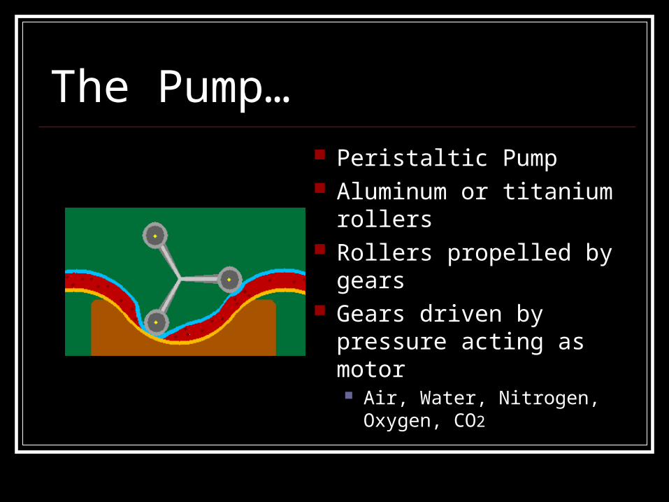
The Pump… Peristaltic Pump Aluminum or titanium
rollers Rollers propelled by gears Gears driven by pressure
acting as motor Air, Water, Nitrogen, Oxygen,
CO2

Broader View:
Pressu
reP
ressure
Pressu
reP
ressure
To Patient
Saline Line Contrast Line
Gears to control roller
spin rate
Rollers

Problems
MRI interference Running cables from control room Safety of propelling gears
Advantages Saving money Set-up time reduced Preparation minimal Allows bolus & infusion to take place
during same scan

Design Option 1 Use a force driven
syringe pump Force source
possibilities Gravity, gas under
pressure, elastic materials, liquid under pressure, or dielastic actuators

Design Option 2
Peristaltic pump powered by a flywheel and gear system Allows great flexibility
when choosing type of power source
Minimizes potential for air bubbles
Easy to sterilize Can be made with
nonferrous materials

Design Option 3
System applying force to bag reservoirs. Will be difficult if not impossible to determine
outflow volume with a changing bag volume. How to apply force throughout the procedure as
the bag is reduced in size?

References http://www.maztravel.com/enrique/tour3.html http://
www.animatedsoftware.com/pumpglos/pumpglos.htm
www.medrad.com www.edmond/wheelchair.com/i_v__stands.htm