MPLAB IDE PROJECT TUTORIALS FOR THIRD PARTY … · MPLAB® IDE PROJECT TUTORIALS FOR THIRD PARTY...
104
2000 Microchip Technology Inc. DS51234A MPLAB ® IDE PROJECT TUTORIALS FOR THIRD PARTY TOOLS Information contained in this publication regarding device applications and the like is intended by way of suggestion only. No representation or warranty is given and no liability is assumed by Microchip Technology Incorporated with respect to the accuracy or use of such information. Use of Microchip’s products as critical components in life support systems is not authorized except with express written approval by Microchip. 2000 Microchip Technology Incorporated. All rights reserved. The Microchip logo and name, PIC, PICmicro, PICSTART, PRO MATE, KEELOQ, and MPLAB are registered trademarks of Microchip Technology Incorporated in the U.S.A. and other countries. PICC, PICC Lite, PICBASIC, PICBASIC PRO, In-Circuit Serial Programming and ICSP are trademarks of Microchip Technology in the U.S.A. and other countries. Intel and Pentium are registered trademarks of Intel Corporation. Microsoft, Internet Explorer, Windows, Windows NT, Windows 2000, and IntelliMouse are registered trademarks of Microsoft Corporation in the United States and/or other countries. Netscape is a registered trademark of Netscape Communications Corporation in the United States and/or other countries. All product/company trademarks mentioned herein are the property of their respective companies.
Transcript of MPLAB IDE PROJECT TUTORIALS FOR THIRD PARTY … · MPLAB® IDE PROJECT TUTORIALS FOR THIRD PARTY...

MPLAB® IDEPROJECT TUTORIALS
FOR THIRD PARTY TOOLS
Information contained in this publication regarding device applications and the like is intended by way of suggestiononly. No representation or warranty is given and no liability is assumed by Microchip Technology Incorporated withrespect to the accuracy or use of such information. Use of Microchip’s products as critical components in life supportsystems is not authorized except with express written approval by Microchip.
2000 Microchip Technology Incorporated. All rights reserved.
The Microchip logo and name, PIC, PICmicro, PICSTART, PRO MATE, KEELOQ, and MPLAB are registered trademarksof Microchip Technology Incorporated in the U.S.A. and other countries. PICC, PICC Lite, PICBASIC, PICBASIC PRO,In-Circuit Serial Programming and ICSP are trademarks of Microchip Technology in the U.S.A. and other countries.
Intel and Pentium are registered trademarks of Intel Corporation.
Microsoft, Internet Explorer, Windows, Windows NT, Windows 2000, and IntelliMouse are registered trademarks ofMicrosoft Corporation in the United States and/or other countries.
Netscape is a registered trademark of Netscape Communications Corporation in the United States and/or othercountries.
All product/company trademarks mentioned herein are the property of their respective companies.
2000 Microchip Technology Inc. DS51234A

MPLAB® IDE Project Tutorials
DS51234A 2000 Microchip Technology Inc.

MPLAB® IDE PROJECT TUTORIALS
Table of Contents
PrefaceIntroduction ...............................................................................................vii
Highlights ..................................................................................................vii
About This Guide ......................................................................................vii
Warranty Registration ................................................................................ix
Recommended Reading ............................................................................ x
Troubleshooting ......................................................................................... x
The Microchip Internet Web Site ...............................................................xi
Development Systems Customer Notification Service .............................xii
Customer Support ...................................................................................xiv
Chapter 1. Project Overview - Third Party Language Tools1.1 Introduction ..................................................................................... 1
1.2 Highlights ........................................................................................ 1
1.3 Overview of Projects ....................................................................... 1
1.4 Preliminary Setup of MPLAB IDE ................................................... 3
1.5 Integrating Other Tools into MPLAB IDE ........................................ 4
Chapter 2. Project Overview - HI-TECH PICC™ Tools
2.1 Introduction ..................................................................................... 7
2.2 Highlights ........................................................................................ 7
2.3 Overview of Projects with HI-TECH PICC Tools ............................ 7
2.4 Preliminary Setup of MPLAB IDE with PICC Tools ........................ 9
Chapter 3. Single Source File Project using PICC™ Tools3.1 Introduction ................................................................................... 15
3.2 Highlights ...................................................................................... 15
3.3 Overview of One Source File Project ............................................ 15
3.4 Create Source File ........................................................................ 16
2000 Microchip Technology Inc. DS51234A-page iii

MPLAB® IDE Project Tutorials
3.5 Set Development Mode .................................................................17
3.6 Create New Project .......................................................................17
3.7 Edit Project ....................................................................................18
3.8 Set Node Properties for Target Node ............................................19
3.9 Add Source File .............................................................................20
3.10 Finish Editing Project ....................................................................21
3.11 Debug and Build Project ...............................................................22
3.12 More Project Information ...............................................................24
3.13 Optimization and Other Node Properties ......................................27
Chapter 4. Multiple Source File Project using PICC™ Tools
4.1 Introduction ...................................................................................29
4.2 Highlights ......................................................................................29
4.3 Overview of Multiple Source File Project ......................................29
4.4 Create Source Files ......................................................................30
4.5 Set Development Mode .................................................................31
4.6 Create New Project .......................................................................31
4.7 Edit Project ....................................................................................32
4.8 Set Node Properties for Target Node ............................................33
4.9 Add First Source File .....................................................................34
4.10 Set Node Properties for First Source Node ...................................35
4.11 Add Second Source File ...............................................................37
4.12 Finish Editing Project ....................................................................39
4.13 Debug and Build Project ...............................................................40
4.14 More Project Information ...............................................................42
4.15 Optimization and Other Node Properties ......................................46
Chapter 5. Project Overview - IAR Tools5.1 Introduction ...................................................................................47
5.2 Highlights ......................................................................................47
5.3 Overview of Projects with IAR Tools .............................................47
5.4 Preliminary Setup of MPLAB IDE with IAR Tools .........................49
DS51234A-page iv 2000 Microchip Technology Inc.

Table of Contents
Chapter 6. MPLAB IDE Project using IAR Tools6.1 Introduction ................................................................................... 53
6.2 Highlights ...................................................................................... 53
6.3 Overview of MPLAB IDE Project .................................................. 54
6.4 Create Source Files ...................................................................... 54
6.5 Set Development Mode ................................................................ 55
6.6 Create New Project ....................................................................... 56
6.7 Edit Project ................................................................................... 57
6.8 Set Node Properties for Target Node ........................................... 58
6.9 Add First Source File .................................................................... 59
6.10 Set Node Properties for First Source Node .................................. 60
6.11 Add Second Source File ............................................................... 62
6.12 Finish Editing Project .................................................................... 63
6.13 Debug and Build Project ............................................................... 64
6.14 More Project Information .............................................................. 66
6.15 Optimization and Other Node Properties ...................................... 67
Glossary ...................................................................................................69
Introduction .............................................................................................. 69
Highlights ................................................................................................. 69
Terms ...................................................................................................... 69
Index .........................................................................................................87
Worldwide Sales and Service .................................................................90
2000 Microchip Technology Inc. DS51234A-page v

MPLAB® IDE Project Tutorials
DS51234A-page vi 2000 Microchip Technology Inc.

®
MPLAB IDE PROJECT TUTORIALSPreface
IntroductionThis first chapter contains general information that will be useful to know before using the tutorials.
HighlightsThe information you will garner from this chapter:
• About this Guide
• Warranty Registration
• Recommended Reading
• Troubleshooting
• The Microchip Technology Internet Web Site
• Development Systems Customer Notification Service
• Customer Support
About This Guide
Document LayoutThis document describes how to use third party development tools with MPLAB IDE. The manual layout is as follows:
• Preface – This section.
• Chapter 1: Project Overview - Third Party Tools – Describes in gen-eral how to use MPLAB IDE with third party tools.
• Chapter 2: Project Overview - HI-TECH PICC™ Tools – Describes specifically how to use MPLAB IDE with HI-TECH PICC tools. Includes setup information.
• Chapter 3: Single Source File Project using PICC Tools– Walks you through making an MPLAB IDE project with PICC tools using one source file.
• Chapter 4: Multiple Source File Project using PICC Tools – Walks you through making an MPLAB IDE project with PICC tools using sev-eral source files.
• Chapter 5: Project Overview - IAR Tools – Describes specifically how to use MPLAB IDE with IAR tools. Includes setup information.
2000 Microchip Technology Inc. DS51234A-page vii

MPLAB® IDE Project Tutorials
• Chapter 4: MPLAB IDE Project using IAR Tools – Walks you through making an MPLAB IDE project with IAR tools using either one or sev-eral source files.
• Glossary – A glossary of Microchip terms.
• Index – Cross-reference listing of terms, features, and sections of this document.
• Worldwide Sales and Service – A listing of Microchip sales and service locations and telephone numbers worldwide.
Conventions Used in this GuideThis manual uses the following documentation conventions:
Table: Documentation Conventions
Description Represents Examples
Code (Courier font):
Plain characters Sample codeFilenames and paths
#define STARTc:\autoexec.bat
Angle brackets: < > Variables <label>, <exp>
Square brackets [ ] Optional arguments MPASMWIN [main.asm]
Curly brackets and pipe character: { | }
Choice of mutually exclu-sive argumentsAn OR selection
errorlevel {0|1}
Lower case characters in quotes
Type of data “filename”
Ellipses... Used to imply (but not show) additional text that is not relevant to the example
list [“list_option..., “list_option”]
0xnnn A hexadecimal number where n is a hexadecimal digit
0xFFFF, 0x007A
Italic characters A variable argument; it can be either a type of data (in lower case characters) or a specific example (in upper-case characters).
char isascii (char, ch);
Interface (Helvetica font):
Underlined, italic text with right arrow
A menu selection from the menu bar
File > Save
Bold characters A window or dialog button to click
OK, Cancel
Characters in angle brackets < >
A key on the keyboard <Tab>, <Ctrl-C>
DS51234A-page viii 2000 Microchip Technology Inc.

Preface
Documentation UpdatesAll documentation becomes dated, and this tutorial is no exception. Since MPLAB IDE and other Microchip tools are constantly evolving to meet customer needs, some MPLAB IDE dialogs and/or tool descriptions may differ from those in this document. Please refer to our Web site at http://www.microchip.com to obtain the latest documentation available.
Documentation Numbering ConventionsDocuments are numbered with a “DS” number. The number is located on the bottom of each page, in front of the page number. The numbering convention for the DS Number is: DSXXXXXA,
where:
Warranty RegistrationPlease complete any Warranty Registration Cards and mail them promptly to Microchip Technology or Third Party vendors. Sending in your Microchip Warranty Registration Card entitles you to receive new product updates. Interim software releases are available at the Microchip Web site.
Documents (Helvetica font):
Italic characters Referenced books MPLAB IDE, Simulator, Editor User’s Guide
Table: Documentation Conventions (Continued)
Description Represents Examples
XXXXX = The document number.
A = The revision level of the document.
2000 Microchip Technology Inc. DS51234A-page ix

MPLAB® IDE Project Tutorials
Recommended ReadingThis tutorial describes how to use MPLAB IDE with third party tools. For more information on MPLAB IDE or third party tools, the following is recommended reading.
README Files
For the latest information on Microchip tools (MPLAB IDE, MPASM™ assembler, etc.), read the associated README files (ASCII text files) included with the MPLAB IDE software. Third party tools generally have readme files also, with the most up-to-date information available on the tools.
Help Files
For the the most up-to-date information on using Microchip tools, consult the associated on-line help files (mplab.hlp, mpasm.hlp, etc.) available through the Help menu of MPLAB IDE software. The help files contain updated information that may not be included in documentation.
MPLAB IDE, Simulator, Editor User’s Guide (DS51025)
Comprehensive guide that describes installation and features of Microchip’s MPLAB Integrated Development Environment, including the editor and simulator functions in the MPLAB IDE environment.
Microchip Technology Library CD-ROM (DS00161)
This CD-ROM contains comprehensive application notes, data sheets, and technical briefs for all of Microchip products. To obtain this CD-ROM, contact the nearest Microchip Sales and Service location (see back page).
Third Party Documentation
Third Party tool vendors may have manuals and help files, as well as electronic manuals, available for more information on the use of their tools.
Microsoft® Windows® ManualsThis manual assumes that users are familiar with Microsoft Windows operating system. Many excellent references exist for this software program, and should be consulted for general operation of Windows.
TroubleshootingIf you have difficulty with any of the tutorials, consult MPLAB IDE documentation (MPLAB IDE, Simulator, Editor User’s Guide (DS51025) or MPLAB Help) and/or Third Party documentation for help.
DS51234A-page x 2000 Microchip Technology Inc.

Preface
The Microchip Internet Web SiteMicrochip provides on-line support on the Microchip World Wide Web (WWW) site.
The Web site is used by Microchip as a means to make files and information easily available to customers. To view the site, the user must have access to the Internet and a Web browser, such as Netscape® Communicator or Microsoft® Internet Explorer®. Files are also available for FTP download from our FTP site.
Connecting to the Microchip Internet Web SiteThe Microchip Web site is available by using your favorite Internet browser to attach to:
http://www.microchip.com
The file transfer site is available by using an FTP service to connect to:
ftp://ftp.microchip.com
The Web site and file transfer site provide a variety of services. Users may download files for the latest Development Tools, Data Sheets, Application Notes, User’s Guides, Articles, and Sample Programs. A variety of Microchip specific business information is also available, including listings of Microchip sales offices, distributors and factory representatives. Other data available for consideration is:
• Latest Microchip Press Releases
• Technical Support Section with Frequently Asked Questions
• Design Tips
• Device Errata
• Job Postings
• Microchip Consultant Program Member Listing
• Links to other useful Web sites related to Microchip Products
• Conferences for products, Development Systems, technical information
• Listing of seminars and events
2000 Microchip Technology Inc. DS51234A-page xi

MPLAB® IDE Project Tutorials
Development Systems Customer Notification ServiceMicrochip provides a customer notification service to help our customers keep current on Microchip products with the least amount of effort. Once you subscribe to one of our list servers, you will receive e-mail notification whenever we change, update, revise or have errata related to that product family or development tool. See the Microchip Web site at www.microchip.com.
The Development Systems list names are:
• Compilers
• Emulators
• Programmers
• MPLAB
• Otools (Other Tools)
Once you have determined the names of the lists that you are interested in, you can subscribe by sending a message to:
with the following as the body:
subscribe <listname> yourname
Here is an example:
subscribe mplab John Doe
To UNSUBSCRIBE from these lists, send a message to:
with the following as the body:
unsubscribe <listname> yourname
Here is an example:
unsubscribe mplab John Doe
The following sections provide descriptions of the available Development Systems lists.
CompilersThe latest information on Microchip C compilers, assemblers and linkers. These include MPLAB C17, MPLAB C18, MPASM™ assembler, MPLINK™ linker, and MPLIB™ librarian.
To SUBSCRIBE to this list, send a message to:
with the following as the body:
subscribe compilers yourname
DS51234A-page xii 2000 Microchip Technology Inc.
Preface
EmulatorsThe latest information on Microchip In-Circuit Emulators. These include MPLAB ICE emulators.
To SUBSCRIBE to this list, send a message to:
with the following as the body:
subscribe emulators yourname
ProgrammersThe latest information on Microchip PICmicro® microcontroller (MCU) device programmers. These include PRO MATE® II and PICSTART® Plus.
To SUBSCRIBE to this list, send a message to:
with the following as the body:
subscribe programmers yourname
MPLABThe latest information on Microchip MPLAB IDE, the Windows Integrated Development Environment for development systems tools. This list is focused on MPLAB IDE, MPLAB SIM, MPLAB IDE Project Manager and general editing and debugging features. For specific information on MPLAB IDE compilers, linkers and assemblers, subscribe to the COMPILERS list. For specific information on MPLAB IDE emulators, subscribe to the EMULATORS list. For specific information on MPLAB IDE device programmers, please subscribe to the PROGRAMMERS list.
To SUBSCRIBE to this list, send a message to:
with the following as the body:
subscribe mplab yourname
Otools (Other Tools)The latest information on other development system tools provided by Microchip. For specific information on MPLAB IDE and its integrated tools refer to the other mail lists.
To SUBSCRIBE to this list, send a message to:
with the following as the body:
subscribe otools yourname
2000 Microchip Technology Inc. DS51234A-page xiii

MPLAB® IDE Project Tutorials
Customer SupportUsers of Microchip products can receive assistance through several channels:
• Distributor or Representative
• Local Sales Office
• Field Application Engineer (FAE)
• Corporate Applications Engineer (CAE)
• Hotline
Customers should call their distributor, representative or field application engineer (FAE) for support. Local sales offices are also available to help customers. See the back cover for a listing of sales offices and locations.
Corporate applications engineers (CAEs) may be contacted at (480) 792-7627.
In addition, there is a Systems Information and Upgrade Line. This line provides system users a listing of the latest versions of all of Microchip’s development systems software products. Plus, this line provides information on how customers can receive any currently available upgrade kits.
The Hotline Numbers are:
1-800-755-2345 for U.S. and most of Canada.
1-480-792-7302 for the rest of the world.
DS51234A-page xiv 2000 Microchip Technology Inc.

®
MPLAB IDE PROJECT TUTORIALSChapter 1. Project Overview - Third Party Language Tools
1.1 IntroductionThis chapter gives an overview of using projects in MPLAB IDE with third party language tools.
1.2 HighlightsThis chapter discusses:
• Overview of Projects
• Preliminary Setup of MPLAB IDE
• Integrating Other Tools into MPLAB IDE
1.3 Overview of ProjectsSeveral third party language tools work with MPLAB IDE. These tools may be used as part of an MPLAB IDE Project. A project in MPLAB IDE is a group of files needed to build an application, along with their associations to various build tools. See the MPLAB IDE, Simulator, Editor User’s Guide (DS51025) for more information on MPLAB IDE and MPLAB IDE Projects.
Figure 1.1 shows a generic MPLAB IDE Project.
2000 Microchip Technology Inc. DS51234A-page 1

MPLAB® IDE Project Tutorials
Figure 1.1: Project Relationships
Linker
Compiler Assembler
sourcefiles
objectfiles
linker scriptlibrary &
outputfiles
main.c prog.asm
main.o prog.o
math.lib device.lkr
prog.hex prog.mapprog.lstprog.codprog.out
files
MPLAB SIM MPLAB ICE PRO MATE® IIPICSTART® Plus
ASSEMBLER/COMPILER
LINKER
SIMULATOR/EMULATORS/PROGRAMMERS
MPLAB IDE Project
precomp.o
DS51234A-page 2 2000 Microchip Technology Inc.

Project Overview - Third Party Language Tools
In this MPLAB IDE Project, the C source file main.c is associated with a compiler. MPLAB IDE will use this information to generate an object file (main.o) for input into a linker.
An assembly source file (prog.asm) is shown also with its associated assembler. MPLAB IDE will use this information to generate the object file prog.o for input into a linker.
In addition, precompiled object files (precomp.o) may be included in a project, with no associated tool required. Types of precompiled object files that are generally required in a project are:
• Start up code
• Initialization code
• Interrupt service routines
• Register definitions
Precompiled object files are often device and/or memory model dependent.
Some library files (math.lib) may be available with the tools. Others may be built outside the project using a librarian tool.
The object files, along with library files and a linker script file (device.lkr) are used to generate the project output files via a linker.
The main output file generated from a linker is the HEX file (prog.hex), used by simulators (MPLAB SIM), emulators (MPLAB ICE) and programmers (PRO MATE II and PICSTART Plus). The other possible output files are:
• COFF file (.out). Intermediate file used to generate Code file, HEX file, and Listing file.
• Code file (.cod). Debug file used by MPLAB IDE.
• Listing file (.lst). Original source code, side-by-side with final binary code.
• Map file (.map). Shows the memory layout after linking. Indicates used and unused memory regions.
For information on available third party tools, please refer to the Third Party Guide (DS00104) for more information.
1.4 Preliminary Setup of MPLAB IDEIn order to use third party language tools with MPLAB IDE you must:
• Install MPLAB IDE. The latest version of this free software is available at our Web site (http://www.microchip.com) or from any sales office (back cover).
• Install the Third Party Tool. Consult the tool documentation for how to install.
2000 Microchip Technology Inc. DS51234A-page 3

MPLAB® IDE Project Tutorials
In general, you will need to set up MPLAB IDE first as follows:
• Specific Third Party Setup - You may need to set up environmental vari-ables for the third party tool to operate correctly.
• Install Language Tools - You will need to install the third party tools using the Install Language Tool dialog (Project > Install Language Tool) so that MPLAB IDE can use them.
1.5 Integrating Other Tools into MPLAB IDEIn order to integrate with MPLAB IDE, third party tool executables should have these properties:
• All input must be received from the command line.
• Do NOT wait on user input.
• Do NOT emit messages to the error stream (stderr, cerr). MPLAB IDE can find error messages in an error file (sourcename.err) or on the standard output stream (stdout, cout). Make all output go to the DOS™ window or an error file (not in a special error window or screen).
Look at the files with extension.mtc in the MPLAB IDE installation directory. These set up the command line switches for the Node Properties dialogs. Then look at the tlxxxx.ini. This has the name of the tool group which MPLAB IDE will show in its Project dialog. The last line points to the name of the associated *.mtc file(s).
• Support files for HI-TECH's PICC™ products are:
- tlhitech.ini
- picc_cmp.mtc
- picc_asm.mtc
- picc_lkr.mtc
• Support files for HI-TECH's PICC Lite™ products are:
- tlpicl.ini
- picl_cmp.mtc
- picl_asm.mtc
- picl_lkr.mtc
• Support for IAR's products are:
- tliar.ini
- iara.mtc
- iarc.mtc
- iarl.mtc
DS51234A-page 4 2000 Microchip Technology Inc.

Project Overview - Third Party Language Tools
• Support files for microEngineering Labs PICBASIC™ products, includ-ing PICBASIC and PICBASIC PRO™ compilers are:
- tlmelabs.ini
- pbp.mtc
- pbc.mtc
• Support files for CCS (Custom Computer Services) C-language compil-ers, including PCB, PCH, and PCM are:
- tlcss.ini
- ccsc.mtc
• Support files for Byte Craft's products are
- tlbcraft.ini
- mpc.mtc
2000 Microchip Technology Inc. DS51234A-page 5

MPLAB® IDE Project Tutorials
NOTES:
DS51234A-page 6 2000 Microchip Technology Inc.

®
MPLAB IDE PROJECT TUTORIALSChapter 2. Project Overview - HI-TECH PICC™ Tools
2.1 IntroductionThis chapter gives an overview of using projects in MPLAB IDE with the HI-TECH PICC tool. Chapter 3 and Chapter 4 discuss in detail how to make single source file and multiple source file MPLAB IDE projects with PICC tools, respectively.
2.2 HighlightsThis chapter discusses:
• Overview of Projects with HI-TECH PICC Tools
• Preliminary Setup of MPLAB IDE with PICC Tools
The next two chapters discuss:
• Single Source File Project using PICC Tools
• Multiple Source File Project using PICC Tools
2.3 Overview of Projects with HI-TECH PICC ToolsThere are several versions of HI-TECH PICC tools:
• PICC tools (picc.exe) - Compiler, assembler and linker for PICmicro® MCU code development.
• PICC Lite™ tools (picl.exe) - Free demo version of the PICC tools that only support PIC16X8X devices.
• PICC tools demo - Free demo version of the PICC tools that only work with the HI-TECH development environment, NOT MPLAB IDE.
PICC tools may be used with MPLAB IDE running under Windows® 3.1x, Windows 95/98 or Windows NT®/2000.
PICC tools are one group of several third party language tools that work with MPLAB IDE. These tools may be used as part of an MPLAB IDE Project. A project in MPLAB IDE is a group of files needed to build an application, along with their associations to various build tools. See the MPLAB IDE, Simulator, Editor User’s Guide (DS51025) for more information on MPLAB IDE and MPLAB IDE Projects.
Figure 2.1 shows a generic MPLAB IDE Project using PICC tools.
2000 Microchip Technology Inc. DS51234A-page 7

MPLAB® IDE Project Tutorials
Figure 2.1: Project Relationships
PICC Linker
PICC Compiler PICC Assembler
sourcefiles
objectfiles
outputfiles
main.c prog.asm
main.obj prog.obj
prog.hex prog.mapprog.lstprog.cod
MPLAB SIM MPLAB ICE PRO MATE® IIPICSTART® Plus
ASSEMBLER/COMPILER
LINKER
SIMULATOR/EMULATORS/PROGRAMMERS
MPLAB IDE Project
precomp.obj
librarymath.obj
files
DS51234A-page 8 2000 Microchip Technology Inc.

Project Overview - HI-TECH PICC™ Tools
In this MPLAB IDE Project, the C source file main.c is associated with the PICC Compiler. MPLAB IDE will use this information to generate an object file (main.obj) for input into the linker (PICC Linker).
An assembly source file (prog.asm) is shown also with its associated assembler (PICC Assembler). MPLAB IDE will use this information to generate the object file prog.obj for input into the linker.
In addition, precompiled object files (precomp.obj) may be included in a project, with no associated tool required.
Standard library files are available with the compiler. Others (math.obj) may be built outside the project using the librarian tool, LIBR (libr.exe). See HI-TECH documentation for more information on using the librarian.
The object files, along with library files, are used to generate the project output files via the linker.
The main output file generated by the linker is the HEX file (prog.hex), used by simulators (MPLAB SIM), emulators (MPLAB ICE) and programmers (PRO MATE II and PICSTART Plus). The other output files are:
• Code file (.cod). Debug file used by MPLAB IDE.
• Listing file (.lst). Original source code, side-by-side with final binary code.
• Map file (.map). Shows the memory layout after linking. Indicates used and unused memory regions.
For more information on using HI-TECH PICC tools, please see the documentation you received with your PICC tools or visit HI-TECH’s Web site (http://www.htsoft.com).
2.4 Preliminary Setup of MPLAB IDE with PICC ToolsIn order to use PICC tools with MPLAB IDE you must:
• Install MPLAB IDE. The latest version of this free software is available at our Web site (http://www.microchip.com) or from any sales office (back cover).
• Install PICC tools. Consult the HI-TECH documentation on how to do this.
No matter what type of project you choose to use (single file or multiple file), you will need to set up MPLAB IDE first as follows:
• Error/Warning Formatting - Set up error/warning output formatting for Windows 3.1x/95/98, Windows NT 4.0 or Windows 2000.
• Install PICC or PICC Lite Language Tools - Install the HI-TECH tools so that MPLAB IDE can use them. Select either picc.exe (all PICmicro® devices) or picl.exe (only PIC16X8X devices).
2000 Microchip Technology Inc. DS51234A-page 9

MPLAB® IDE Project Tutorials
2.4.1 Error/Warning Formatting - Windows 3.1x/95/98Place these two statements in the autoexec.bat file:
SET HTC_ERR_FORMAT=Error[ ] file %%f %%l : %%s
SET HTC_WARN_FORMAT=Warning[ ] file %%f %%l : %%s
2.4.2 Error/Warning Formatting - Windows NT 4.0Right-click on the My Computer icon on your desktop and select Properties from the pop-up menu. The Systems Properties dialog will appear. Click on the Environment tab. To enter a new variable, click in the Variable box and type the name of a new variable. Then click in the Value box and enter the value.
Enter the following two new variables:
1. Variable: HTC_ERR_FORMAT
Value: Error[000 ] file %f %l : %s
2. Variable: HTC_WARN_FORMAT
Value: Warning[000 ] file %f %l : %s
When done, click OK.
2.4.3 Error/Warning Formatting - Windows 2000Right-click on the My Computer icon on your desktop and select Properties from the pop-up menu. The Systems Properties dialog will appear. Click on the Advanced tab. Under User Variables, click New. The New User Variables dialog appears. To enter a new variable, click in the Variable Name box and type the name of a new variable. Then click in the Variable Value box and enter the value.
Enter the following two new variables:
1. Variable Name: HTC_ERR_FORMAT
Variable Value: Error[000 ] file %f %l : %s
2. Variable Name: HTC_WARN_FORMAT
Variable Value: Warning[000 ] file %f %l : %s
When done, click OK in each dialog.
Note: You will have to reboot your PC for these changes to take affect.
DS51234A-page 10 2000 Microchip Technology Inc.

Project Overview - HI-TECH PICC™ Tools
2.4.4 Install PICC Language ToolsStart up MPLAB IDE. Select Project > Install Language Tool. The Install Language Tool dialog will appear.
1. Select HI-TECH as the Language Suite.2. Check to see that each Tool Name has an associated Executable. If not,
select the Executable picc.exe for the assembler, compiler and linkertool as shown in the following figures (your executable path may be dif-ferent.) Use the Browse button to locate picc.exe on your system, bydefault in the c:\ht-pic\bin directory.
3. The Command-line option should be selected for all tools.4. When done, click OK.
Figure 2.2: Install Language Tool Dialog – PICC Compiler
Figure 2.3: Install Language Tool Dialog – PICC Linker
1
2
4
2
3
1
2
4
2
3
2000 Microchip Technology Inc. DS51234A-page 11

MPLAB® IDE Project Tutorials
Figure 2.4: Install Language Tool Dialog – PICC Assembler
2.4.5 Install PICC Lite Language ToolsStart up MPLAB IDE. Select Project > Install Language Tool. The Install Language Tool dialog will appear.
1. Select HI-TECH PICL as the Language Suite.2. Check to see that each Tool Name has an associated Executable. If not,
select the Executable picl.exe for the assembler, compiler and linkertool as shown in the following figures (your executable path may be dif-ferent.) Use the Browse button to locate picl.exe on your system, bydefault in the c:\picclite\bin directory.
3. The Command-line option should be selected for all tools.4. When done, click OK.
Figure 2.5: Install Language Tool Dialog – PICC Lite Compiler
1
2
4
2
3
1
2
4
2
3
DS51234A-page 12 2000 Microchip Technology Inc.

Project Overview - HI-TECH PICC™ Tools
Figure 2.6: Install Language Tool Dialog – PICC Lite Linker
Figure 2.7: Install Language Tool Dialog – PICC Lite Assembler
1
2
4
2
3
1
2
4
2
3
2000 Microchip Technology Inc. DS51234A-page 13

MPLAB® IDE Project Tutorials
NOTES:
DS51234A-page 14 2000 Microchip Technology Inc.

®
MPLAB IDE PROJECT TUTORIALSChapter 3. Single Source File Project using PICC™ Tools
3.1 IntroductionThis chapter will guide you, step by step, in making an MPLAB IDE Project with one source file using HI-TECH PICC tools.
3.2 HighlightsIn this tutorial, you will learn how to:
• Create the source file
• Set the MPLAB IDE development mode
• Create a new project
• Set project Node Properties (PICC Compiler)
• Add the source file
• Debug and build the project
3.3 Overview of One Source File ProjectFigure 3.1 gives a graphical overview of the MPLAB IDE Project using PICC tools. The source file ex1.c is associated with the compiler to produce the object file ex1.obj. This file is used by the linker to produce the main output file, ex1.hex.
Figure 3.1: Project Relationships For PICC Source Files
PICC Compiler
ex1.csourcefiles
main outputfile
ex1.hex
LINKERPICC Linker
objectfiles
ASSEMBLER/COMPILER
ex1.obj
2000 Microchip Technology Inc. DS51234A-page 15
MPLAB® IDE Project Tutorials
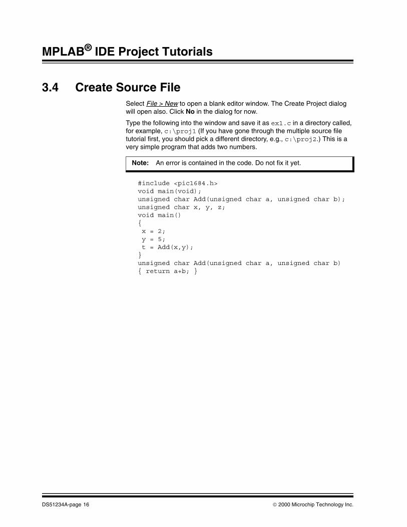
3.4 Create Source FileSelect File > New to open a blank editor window. The Create Project dialog will open also. Click No in the dialog for now.
Type the following into the window and save it as ex1.c in a directory called, for example, c:\proj1 (If you have gone through the multiple source file tutorial first, you should pick a different directory, e.g., c:\proj2.) This is a very simple program that adds two numbers.
#include <pic1684.h>void main(void);unsigned char Add(unsigned char a, unsigned char b);unsigned char x, y, z;void main(){ x = 2; y = 5; t = Add(x,y);}unsigned char Add(unsigned char a, unsigned char b){ return a+b; }
Note: An error is contained in the code. Do not fix it yet.
DS51234A-page 16 2000 Microchip Technology Inc.

Single Source File Project using PICC™ Tools
3.5 Set Development ModeSelect Options > Development Mode to open the Development Mode dialog.
1. Click the Tools tab. 2. Select MPLAB SIM simulator3. Select the PIC16F84 PICmicro® MCU for this example. 4. Click OK.
Figure 3.2: Development Mode Dialog – MPLAB SIM, PIC16F84
3.6 Create New ProjectSelect Project > New Project to open the New Project dialog.
1. Select the directory containing the source file as the directory for a newproject.
2. Name the project ex1.PJT.3. Click OK.
Figure 3.3: New Project Dialog – ex1.pjt
1
23
4
2 13
2000 Microchip Technology Inc. DS51234A-page 17

MPLAB® IDE Project Tutorials
3.7 Edit ProjectThe Edit Project dialog has several sections.
1. In the Project section, enter the Include Path, (e.g., c:\ht-pic\include). This information lets MPLAB IDE know whereto find the HI-TECH include files, *.h.
2. Select HI-TECH as the Language Tool Suite. The Change Suite Warningdialog will open. Click OK.
3. In the Project Files section, click on ex1 [.hex] to highlight the HEXfile name and activate the Node Properties button.
4. Click on Node Properties.
Figure 3.4: Edit Project Dialog – ex1.hex
1
3
2
4
DS51234A-page 18 2000 Microchip Technology Inc.

Single Source File Project using PICC™ Tools
3.8 Set Node Properties for Target NodeThe Node Properties dialog should now be open.
1. Set the Language Tool to PICC Compiler.2. The command line switches for the selected language tool are shown
descriptively in Options. When you first open this dialog, the checkedboxes represent the default values for the tool. For more information oneach option, consult HI-TECH documentation.
For this tutorial, several setting needs to be changed, as shown inFigure 3.5 and described below.
Figure 3.5: Node Properties Dialog – ex1.hex
Make the following changes in the Options section:
• Select Generate Debug Info
• Select Error File and add an error file name to the Data column, (i.e., ex1.err).
• Select Display Memory Usage
• Select Map File and add a map file name to the Data column, (i.e., ex1.map).
• Select Assembler List File to generate ex1.lst.
3. Command line switches are also shown in Command Line. Refer to theHI-TECH documentation for more information on these switches.
4. Click in the text box for Additional Command Line Options and type -FAKELOCAL (supported for PICC tools version 7.84 and above).
5. Click OK to return to the Edit Project dialog.
12
3
5
4
2000 Microchip Technology Inc. DS51234A-page 19

MPLAB® IDE Project Tutorials
3.9 Add Source FileThe Add Node button on the Edit Project dialog should now be active.
1. Click on it to open the Add Node dialog.
Figure 3.6: Edit Project Dialog – Add Node
In the Add Node dialog (Figure 3.7):
1. Add the source file, ex1.c from the source file directory2. Click OK to return to the Edit Project dialog.
1
DS51234A-page 20 2000 Microchip Technology Inc.

Single Source File Project using PICC™ Tools
Figure 3.7: Add Node Dialog – ex1.c
3.10 Finish Editing ProjectTo finish editing the project;
1. Click OK to close the Edit Project dialog.
Figure 3.8: Edit Project Dialog – Final
2
1
1
2000 Microchip Technology Inc. DS51234A-page 21

MPLAB® IDE Project Tutorials
3.11 Debug and Build ProjectSelect Project > Make Project from the menu to compile the application using the HI-TECH compiler. A Build Results window is created that shows;
1. The command line sent to the compiler, along with other informationspecified in Node Properties
2. Compilation errors3. A compiler error will cause the build to fail, meaning a HEX file is not gen-
erated, and therefore MPLAB IDE will be unable to find this file.
Figure 3.9: Build Results Window – Build Failed
If you have a build error, double-click on the error in the Build Results window to send you to the line in the source file that contains that error. If the source code file is not open, MPLAB IDE will open the file and then go to the line containing the error.
Alternatively, you can click on the error in the error file to accomplish the same result. By selecting Error File in the Node Properties dialog, an error file is created with the name given in the Data field.
To open the error file, select File > Open and then choose All Files (*.*) from the List of file types. Choose the .err file and click OK.
Figure 3.10: Assembler List File Window – ex1.err
123
DS51234A-page 22 2000 Microchip Technology Inc.

Single Source File Project using PICC™ Tools
Now you will fix the error in the source code.
1. Change the "t" to a "z"
Figure 3.11: Source Code with Error
Select File > Save (This step is just good practice, but not necessary, as MPLAB IDE will save the file when doing a build.) Now build the project again by selecting Project > Make Project. The Build Results window should now look different.
1. The command line sent to the compiler is still displayed, along with otherinformation specified in Node Properties.
2. By selecting Display Memory Usage in the Node Properties dialog,Psect (Section) Usage Map and the Memory Usage Map are shown inthe Build Results window. These usage maps display complete memorysegment usage after linking.
For HI-TECH tools, the linker is called by the compiler automatically, (i.e.,you do not need to specify its use in conjunction with a node for single-node projects).
3. Build was successful.
1
2000 Microchip Technology Inc. DS51234A-page 23

MPLAB® IDE Project Tutorials
Figure 3.12: Build Results Window – Build Successful
3.12 More Project InformationThe source code in this tutorial only had one error. However, real untested code would most likely need to be debugged more extensively. This is where the options that you set in Node Properties will help out.
3.12.1 Debug InformationBy selecting Generate Debug Info in the Node Properties dialog, the MPLAB IDE has information necessary to help you debug your code.
3.12.2 Map FileBy selecting Map File in the Node Properties dialog, a map file is created with the name given in the Data field. To open the map file, select Window > Map File (Figure 3.13). For information on the content of the map file, please refer to HI-TECH documentation.
1
2
3
2
DS51234A-page 24 2000 Microchip Technology Inc.

Single Source File Project using PICC™ Tools
Figure 3.13: Map File Window – ex1.map
3.12.3 Absolute ListingBy selecting Assembler List File in the Node Properties dialog, an absolute listing file is generated. The list file shows both the original C code, the generated assembler code and the corresponding binary code.
Figure 3.14: Assembler List File Window – ex1.lst
2000 Microchip Technology Inc. DS51234A-page 25

MPLAB® IDE Project Tutorials
3.12.4 Symbol ListBy setting -FAKELOCAL under Additional Command Line Options in the Node Properties dialog, local auto variables will appear and have a value when single stepping inside the function.
Open the Symbol List by selecting Window > Show Symbol List. Scroll through the variable list to make sure any local variables in your code are listed.
Figure 3.15: Symbol List Window
DS51234A-page 26 2000 Microchip Technology Inc.

Single Source File Project using PICC™ Tools
3.12.5 Project WindowOpen the Window > Project window. This displays various project information, which can be useful to review when debugging.
Figure 3.16: Project Window – ex1.pjt
Double-clicking on any of the blue file names, you can open these files in the MPLAB IDE. This is ideal for opening files that are not in the project directory (e.g., header .h files), and therefore would require hunting through directory structures to find otherwise.
3.13 Optimization and Other Node PropertiesFor more information on optimization techniques, (e.g., Local and Global Optimization switches), as well as definitions of other Node Properties switches, please refer to HI-TECH documentation.
2000 Microchip Technology Inc. DS51234A-page 27

MPLAB® IDE Project Tutorials
NOTES:
DS51234A-page 28 2000 Microchip Technology Inc.

®
MPLAB IDE PROJECT TUTORIALSChapter 4. Multiple Source File Project using PICC™ Tools
4.1 IntroductionThis chapter will guide you, step by step, in making an MPLAB IDE Project with several source files using HI-TECH PICC tools.
4.2 HighlightsIn this tutorial, you will learn how to:
• Create the source files
• Set the MPLAB IDE development mode
• Create a new project
• Set project Node Properties (PICC Linker)
• Add the source files and set Node Properties (PICC Compiler)
• Debug and build the project
4.3 Overview of Multiple Source File ProjectFigure 4.1 gives a graphical overview of the MPLAB IDE Project using PICC tools. The source files ex1.c and add.c are associated with the compiler to produce the object files ex1.obj and add.obj. These files are used by the linker to produce the main output file, ex1.hex.
Figure 4.1: Project Relationships For PICC Source Files
PICC Compiler
ex1.csourcefiles
main outputfile
ex1.hex
LINKERPICC Linker
objectfiles
ASSEMBLER/COMPILER
ex1.obj
PICC Compiler
add.c
add.obj
2000 Microchip Technology Inc. DS51234A-page 29

MPLAB® IDE Project Tutorials
4.4 Create Source FilesSelect File > New to open a blank editor window. The Create Project dialog will open also. Click No in the dialog for now.
Type the following into the window and save it as ex1.c in a directory called, for example, c:\proj1 (If you have gone through the single source file tutorial first, you should pick a different directory, e.g., c:\proj2). This is a very simple program that adds two numbers.
#include <pic1684.h>void main(void);unsigned char Add(unsigned char a, unsigned char b);unsigned char x, y, z;void main(){ x = 2; y = 5; t = Add(x,y);}
Again select File > New to open a blank editor window. Select No in the Create Project dialog. Type the following into the window and save it as add.c in the same directory as the file above.
#include <pic1684.h>unsigned char Add(unsigned char a, unsigned char b){ return a+b; }
Note: An error is contained in the code. Do not fix it yet.
DS51234A-page 30 2000 Microchip Technology Inc.

Multiple Source File Project using PICC™ Tools
4.5 Set Development ModeSelect Options > Development Mode to open the Development Mode dialog.
1. Click the Tools tab. 2. Select MPLAB SIM simulator3. Select the PIC16F84 PICmicro® MCU for this example. 4. Click OK.
Figure 4.2: Development Mode Dialog – MPLAB SIM, PIC16F84
4.6 Create New ProjectSelect Project > New Project to open the New Project dialog.
1. Select the directory containing the source files as the directory for a newproject.
2. Name the project ex1.PJT.3. Click OK.
Figure 4.3: New Project Dialog – ex1.pjt
1
23
4
2 13
2000 Microchip Technology Inc. DS51234A-page 31

MPLAB® IDE Project Tutorials
4.7 Edit ProjectThe Edit Project dialog has several sections.
1. In the Project section, enter the Include Path, (e.g., c:\ht-pic\include). This information lets MPLAB IDE know whereto find the HI-TECH include files, *.h.
2. Select HI-TECH as the Language Tool Suite. The Change Suite Warningdialog will open. Click OK.
3. In the Project Files section, click on ex1 [.hex] to highlight the HEXfile name and activate the Node Properties button.
4. Click on Node Properties.
Figure 4.4: Edit Project Dialog – ex1.hex
1
3
2
4
DS51234A-page 32 2000 Microchip Technology Inc.

Multiple Source File Project using PICC™ Tools
4.8 Set Node Properties for Target NodeThe Node Properties dialog should now be open.
1. Set the Language Tool to PICC Linker.2. The command line switches for the selected language tool are shown
descriptively in Options. When you first open this dialog, the checkedboxes represent the default values for the tool. For more information oneach option, consult HI-TECH documentation.
For this tutorial, several setting needs to be changed, as shown inFigure 4.5 and described below.
Figure 4.5: Node Properties Dialog – ex1.hex
Make the following changes in the Options section:
• Select Generate Debug Info
• Select Map File and add a map file name to the Data column, (i.e., ex1.map).
• Select Display Complete Memory Usage
3. Command line switches are also shown in Command Line. Refer to theHI-TECH documentation for more information on these switches.
4. Click in the text box for Additional Command Line Options and type -FAKELOCAL (supported for PICC tools version 7.84 and above).
5. Click OK to return to the Edit Project dialog.
12
3
5
4
2000 Microchip Technology Inc. DS51234A-page 33

MPLAB® IDE Project Tutorials
4.9 Add First Source FileThe Add Node button on the Edit Project dialog should now be active.
1. Click on it to open the Add Node dialog.
Figure 4.6: Edit Project Dialog – Add Node
In the Add Node dialog (Figure 4.7);
1. Add the source file, ex1.c from the source file directory2. Click OK to return to the Edit Project dialog.
1
DS51234A-page 34 2000 Microchip Technology Inc.

Multiple Source File Project using PICC™ Tools
Figure 4.7: Add Node Dialog – ex1.c
4.10 Set Node Properties for First Source NodeIn the Edit Project dialog;
1. Click on the source file2. Click on Node Properties.
Figure 4.8: Edit Project Dialog – ex1.c
2
1
1
2
2000 Microchip Technology Inc. DS51234A-page 35

MPLAB® IDE Project Tutorials
The Node Properties dialog should now be open.
1. Set the Language Tool to PICC Compiler.2. The command line switches for the selected language tool are shown
descriptively in Options. When you first open this dialog, the checkedboxes represent the default values for the tool.
For this tutorial, several setting needs to be changed, as shown inFigure 4.5 and described below.
Figure 4.9: Node Properties Dialog – ex1.obj
Make the following changes in the Options section:
• Select Generate Debug Info
• Select Error File and add an error file name to the Data column, (i.e., ex1.err).
• Select Assembler List File to generate ex1.lst.
3. Command line switches are also shown in Command Line. Refer to theHI-TECH documentation for more information on these switches.
4. Click in the text box for Additional Command Line Options and type -FAKELOCAL (supported for PICC tools version 7.84 and above.)
5. Click OK to return to the Edit Project dialog.
12
3
5
4
DS51234A-page 36 2000 Microchip Technology Inc.

Multiple Source File Project using PICC™ Tools
4.11 Add Second Source FileAll node buttons on the Edit Project dialog should be active.
1. Click on Copy Node to open the Copy Node dialog.
Figure 4.10: Edit Project Dialog – Copy Node
In the Copy Node dialog (Figure 4.7);
1. Click on the source file, add.c from the source file directory.
This file will be added to the project, with its Node Properties copied fromex1.c.
2. Click OK to return to the Edit Project dialog.
1
2000 Microchip Technology Inc. DS51234A-page 37

MPLAB® IDE Project Tutorials
Figure 4.11: Copy Node Dialog – add.c
In the Edit Project dialog;
1. Click on add [.c].2. Click Node Properties to edit the copied properties from ex1 [.c].
Figure 4.12: Edit Project Dialog – add.c
2
1
1
2
DS51234A-page 38 2000 Microchip Technology Inc.

Multiple Source File Project using PICC™ Tools
In the Node Properties dialog under Options, change the Error File name in the Date column to add.err. Click OK when done.
4.12 Finish Editing ProjectTo finish editing the project;
1. Click OK to close the Edit Project dialog.
Figure 4.13: Edit Project Dialog – Final
1
2000 Microchip Technology Inc. DS51234A-page 39

MPLAB® IDE Project Tutorials
4.13 Debug and Build ProjectSelect Project > Make Project from the menu to compile the application using the HI-TECH compiler. A Build Results window is created that shows;
1. The command line sent to the compiler, along with other informationspecified in Node Properties
2. Compilation errors3. A compiler error will cause the build to fail, meaning an object file is not
generated, and therefore MPLAB IDE will be unable to find this file.
Figure 4.14: Build Results Window – Build Failed
If you have a build error, double-click on the error in the Build Results window to send you to the line in the source file that contains that error. If the source code file is not open, MPLAB IDE will open the file and then go to the line containing the error.
Alternatively, you can click on the error in the error file to accomplish the same result. By selecting Error File in the Node Properties dialog, an error file is created with the name given in the Data field.
To open the error file, select File > Open and then choose All Files (*.*) from the List of file types. Choose the .err file and click OK.
Figure 4.15: Assembler List File Window – ex1.err
123
DS51234A-page 40 2000 Microchip Technology Inc.

Multiple Source File Project using PICC™ Tools
Now you will fix the error in the source code.
1. Change the "t" to a "z"
Figure 4.16: Source Code with Error
Select File > Save (This step is just good practice, but not necessary, as MPLAB IDE will save the file when doing a build.) Now build the project again by selecting Project > Make Project. The Build Results window should now look different.
1. The command line sent to each tool displayed, along with other informa-tion specified in Node Properties.
2. By selecting Display Complete Memory Usage in the target Node Prop-erties dialog, Psect (Section) Usage Map and the Memory Usage Mapare shown in the Build Results window. These usage maps display com-plete memory segment usage after linking.
3. Build was successful.
1
2000 Microchip Technology Inc. DS51234A-page 41

MPLAB® IDE Project Tutorials
Figure 4.17: Build Results Window – Build Successful (2 Views)
4.14 More Project InformationThe source code in this tutorial only had one error. However, real untested code would most likely need to be debugged more extensively. This is where the options that you set in Node Properties will help out.
4.14.1 Debug InformationBy selecting Generate Debug Info in the Node Properties dialog, the MPLAB IDE has information necessary to help you debug your code.
4.14.2 Map FileBy selecting Map File in the Node Properties dialog, a map file is created with the name given in the Data field. To open the map file, select Window > Map File (Figure 4.18). For information on the content of the map file, please refer to HI-TECH documentation.
1
2
3
2
1
1
DS51234A-page 42 2000 Microchip Technology Inc.

Multiple Source File Project using PICC™ Tools
Figure 4.18: Map File Window – ex1.map
4.14.3 Absolute ListingBy selecting Assembler List File in the Node Properties dialog, an absolute listing file is generated. The list file shows both the original C code, the generated assembler code and the corresponding binary code.
Figure 4.19: Assembler List File Window – ex1.lst
2000 Microchip Technology Inc. DS51234A-page 43

MPLAB® IDE Project Tutorials
4.14.4 Symbol ListBy setting -FAKELOCAL under Additional Command Line Options in the Node Properties dialog, local auto variables will appear and have a value when single stepping inside the function.
Open the Symbol List by selecting Window > Show Symbol List. Scroll through the variable list to make sure any local variables in your code are listed.
Figure 4.20: Symbol List Window
DS51234A-page 44 2000 Microchip Technology Inc.

Multiple Source File Project using PICC™ Tools
4.14.5 Project WindowOpen the Window > Project window. This displays various project information, which can be useful to review when debugging.
Figure 4.21: Project Window – ex1.pjt (2 Views)
Double-clicking on any of the blue file names, you can open these files in the MPLAB IDE. This is ideal for opening files that are not in the project directory (e.g., header .h files), and therefore would require hunting through directory structures to find otherwise.
2000 Microchip Technology Inc. DS51234A-page 45

MPLAB® IDE Project Tutorials
4.15 Optimization and Other Node PropertiesFor more information on optimization techniques, (e.g., Local and Global Optimization switches, as well as definitions of other Node Properties switches), please refer to HI-TECH documentation.
DS51234A-page 46 2000 Microchip Technology Inc.

®
MPLAB IDE PROJECT TUTORIALSChapter 5. Project Overview - IAR Tools
5.1 IntroductionThis chapter gives an overview of using projects in MPLAB IDE with the IAR tools. Chapter 6 discusses in detail how to make single source file or multiple source file MPLAB IDE project with IAR tools.
5.2 HighlightsThis chapter discusses:
• Overview of Projects with IAR Tools
• Preliminary Setup of MPLAB IDE with IAR Tools
The next chapter discusses:
• MPLAB IDE Project using IAR Tools
5.3 Overview of Projects with IAR ToolsIAR tools may be used with MPLAB IDE running under Windows® 95/98 or Windows NT® 3.51 or greater. Executables that provide an interface between the IAR tools and the MPLAB IDE are iari.exe (compiler), iarl.exe (linker), and iara.exe (assembler). The relationship between the "wrapper" executables and actual tool executables are shown below.
IAR tools are one group of several third party language tools that work with MPLAB IDE. These tools may be used as part of an MPLAB IDE Project. A project in MPLAB IDE is a group of files needed to build an application, along with their associations to various build tools. See the MPLAB IDE, Simulator, Editer User’s Guide (DS51025) for more information on MPLAB IDE and MPLAB IDE Projects.
Figure 5.1 shows a generic MPLAB IDE Project using the IAR tools.
Tool Name Tool Executable Wrapper Executable
PICmicro® C Compiler iccpic.exe iari.exe
PICmicro® Assembler apic.exe iara.exe
IAR Linker xlink.exe iarl.exe
2000 Microchip Technology Inc. DS51234A-page 47

MPLAB® IDE Project Tutorials
Figure 5.1: Project Relationships
IAR Linker
PICmicro C PICmicro
sourcefiles
objectfiles
outputfiles
main.c prog.s39
main.r39 prog.r39
prog.hex
MPLAB SIM MPLAB ICE PRO MATE® IIPICSTART® Plus
ASSEMBLER/COMPILER
LINKER
SIMULATOR/EMULATORS/PROGRAMMERS
MPLAB IDE Project
precomp.r39
librarymath.r39
files
Compiler Assembler
DS51234A-page 48 2000 Microchip Technology Inc.

Project Overview - IAR Tools
In this MPLAB IDE Project, the C source file main.c is associated with the PICmicro C Compiler. MPLAB IDE will use this information to generate an object file (main.r39) for input into the linker (IAR Linker).
An assembly source file (prog.s39) is shown also with its associated assembler (PICmicro Assembler). MPLAB IDE will use this information to generate the object file prog.r39 for input into the linker.
In addition, precompiled object files (precomp.r39) may be included in a project, with no associated tool required.
Standard library files are available with the compiler, located in the lib subdirectory. Others (math.r39) may be built outside the project using the librarian tool, XLIB (xlib.exe). See IAR documentation for more information on using the librarian.
The object files, along with library files, are used to generate the project output files via the linker.
The main output file generated by the linker is the HEX file (prog.hex), used by simulators (MPLAB SIM), emulators (MPLAB ICE) and programmers (PRO MATE II and PICSTART Plus).
For more information on using IAR tools, please see the documentation you received with your tools or visit IAR’s website (http://www.iar.com).
5.4 Preliminary Setup of MPLAB IDE with IAR ToolsIn order to use IAR tools with MPLAB IDE you must:
• Install MPLAB IDE. The latest version of this free software is available at our Web site (http://www.microchip.com) or from any sales office (back cover).
• Install IAR tools. Consult the IAR documentation on how to install these tools. Once you have installed the software, you may also need to install a hardware dongle for the tools to operate. Again, consult IAR documentation for more details.
No matter what type of project you choose to use (single file or multiple file), you will need to set up MPLAB IDE first as follows:
• Setup Path - Show path to setup directory for Windows 95/98/NT 3.51, Windows NT 4.0 or Windows 2000. This directory contains processor definition files *.i39.
• Install IAR Language Tools - Install the IAR tools so that MPLAB IDE can use them.
2000 Microchip Technology Inc. DS51234A-page 49

MPLAB® IDE Project Tutorials
5.4.1 Setup Path - Windows 95/98/NT 3.51In your autoexec.bat file, set the environment variable QPICINFO to point to the setup directory of the IAR installation. By default this would be:
SET QPICINFO=C:\IAR\EW23\PICMICRO\SETUP\
where the ending backslash is required.
5.4.2 Setup Path - Windows NT 4.0Right-click on the My Computer icon on your desktop and select Properties from the pop-up menu. The Systems Properties dialog will appear. Click on the Environment tab. To enter a new variable, click in the Variable box and type the name of a new variable. Then click in the Value box and enter the value.
Enter the following new variable:
1. Variable: QPICINFO
Value: C:\IAR\EW23\PICMICRO\SETUP\
where Value is the setup path and the ending backslash is required.
When done, click OK.
5.4.3 Setup Path - Windows 2000Right-click on the My Computer icon on your desktop and select Properties from the pop-up menu. The Systems Properties dialog will appear. Click on the Advanced tab. Under User Variables, click New. The New User Variables dialog appears. To enter a new variable, click in the Variable Name box and type the name of a new variable. Then click in the Variable Value box and enter the value.
Enter the following new variable:
1. Variable Name: QPICINFO
Variable Value: C:\IAR\EW23\PICMICRO\SETUP\
where Variable Value is the setup path and the ending backslash isrequired.
When done, click OK in each dialog.
Note: You will have to reboot your PC for this change to take affect.
DS51234A-page 50 2000 Microchip Technology Inc.

Project Overview - IAR Tools
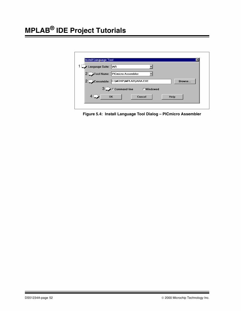
5.4.4 Install IAR Language ToolsStart up MPLAB IDE. Select Project > Install Language Tool. The Install Language Tool dialog will appear.
1. Select IAR as the Language Suite.2. Check to see that each Tool Name has an associated Executable. If not,
select the Executable for the compiler, linker and assembler tool asshown in the following figures (your executable path may be different.)
Currently, the executables iari.exe, iarl.exe and iara.exe maybe found in the MPLAB IDE install directory. They should soon be in thedefault IAR install subdirectory of c:\iar\Ew23\PICmicro\bin. Usethe Browse button to locate each executable on your system.
3. The Command-line option should be selected for all tools.4. When done, click OK.
Figure 5.2: Install Language Tool Dialog – PICmicro C Compiler
Figure 5.3: Install Language Tool Dialog – IAR Linker
1
2
4
2
3
1
2
4
2
3
2000 Microchip Technology Inc. DS51234A-page 51
MPLAB® IDE Project Tutorials
Figure 5.4: Install Language Tool Dialog – PICmicro Assembler
1
2
4
2
3
DS51234A-page 52 2000 Microchip Technology Inc.

®
MPLAB IDE PROJECT TUTORIALSChapter 6. MPLAB IDE Project using IAR Tools
6.1 IntroductionThis chapter will guide you, step by step, in making an MPLAB IDE Project with several source files using IAR tools. A single source file project is created in much the same way, only using one source file instead of the two shown here.
6.2 HighlightsIn this tutorial, you will learn how to:
• Create the source files
• Set the MPLAB IDE development mode
• Create a new project
• Set project Node Properties
• Add the source files and set Node Properties
• Debug and build the project
2000 Microchip Technology Inc. DS51234A-page 53

MPLAB® IDE Project Tutorials
6.3 Overview of MPLAB IDE ProjectFigure 6.1 gives a graphical overview of the MPLAB IDE Project using IAR. The source files ex1.c and add.c are associated with the compiler to produce the object files ex1.r39 and add.r39. These files are used by the linker to produce the main output file, ex1.hex.
Figure 6.1: Project Relationships For IAR Source Files
6.4 Create Source FilesSelect File > New to open a blank editor window. The Create Project dialog will open also. Click No in the dialog for now.
Type the following into the window and save it as ex1.c in a directory called, for example, c:\proj1. This is a very simple program that adds two numbers.
#include <io16f84.h>void main(void);unsigned char Add(unsigned char a, unsigned char b);unsigned char x, y, z;void main(){ x = 2; y = 5; t = Add(x,y);}
PICmicro C Compiler
ex1.csourcefiles
main outputfile
ex1.hex
LINKERIAR Linker
objectfiles
ASSEMBLER/COMPILER
ex1.r39
PICmicro C Compiler
add.c
add.r39
Note: An error is contained in the code. Do not fix it yet.
DS51234A-page 54 2000 Microchip Technology Inc.

MPLAB IDE Project using IAR Tools
Again select File > New to open a blank editor window. Select No in the Create Project dialog. Type the following into the window and save it as add.c in the same directory as the file above.
#include <io16f84.h>unsigned char Add(unsigned char a, unsigned char b){ return a+b; }
6.5 Set Development ModeSelect Options > Development Mode to open the Development Mode dialog.
1. Click the Tools tab. 2. Select MPLAB SIM simulator3. Select the PIC16F84 PICmicro® MCU for this example. 4. Click OK.
Figure 6.2: Development Mode Dialog – MPLAB SIM, PIC16F84
1
23
4
2000 Microchip Technology Inc. DS51234A-page 55

MPLAB® IDE Project Tutorials
6.6 Create New ProjectSelect Project > New Project to open the New Project dialog.
1. Select c:\proj1 as the directory for a new project.2. Name the project ex1.PJT.3. Click OK.
Figure 6.3: New Project Dialog – ex1.pjt
2 13
DS51234A-page 56 2000 Microchip Technology Inc.

MPLAB IDE Project using IAR Tools
6.7 Edit ProjectThe Edit Project dialog is shown in Figure 6.4.
1. Select IAR as the Language Tool Suite. The Change Suite Warning dia-log will open. Click OK.
2. In the Project Files section, click on ex1 [.hex] to highlight the HEXfile name and activate the Node Properties button.
3. Click on Node Properties.
Figure 6.4: Edit Project Dialog – ex1.hex
2
1
3
2000 Microchip Technology Inc. DS51234A-page 57

MPLAB® IDE Project Tutorials
6.8 Set Node Properties for Target NodeThe Node Properties dialog should now be open.
1. Set the Language Tool to IAR Linker.2. The command line switches for the selected language tool are shown
descriptively in Options. When you first open this dialog, the checkedboxes represent the default values for the tool. For more information oneach option, consult IAR documentation.
For this tutorial, several settings need to be changed, as shown inFigure 6.5 and described below.
Figure 6.5: Node Properties Dialog – ex1.hex
Make the following changes in the Options section:
• Select COFF Output Format
• Select Include Search Path and add the following path to the Data col-umn: c:\iar\Ew23\PICmicro\lib.
3. Command line switches are also shown in Command Line. Refer to theIAR documentation for more information on these switches.
4. Click in the text box for Additional Command Line Options and type -f c:\iar\Ew23\PICmicro\iccpic\l16f84.xcl.
5. Click OK to return to the Edit Project dialog.
12
3
5
4
DS51234A-page 58 2000 Microchip Technology Inc.

MPLAB IDE Project using IAR Tools
6.9 Add First Source FileThe Add Node button on the Edit Project dialog should now be active.
1. Click on it to open the Add Node dialog.
Figure 6.6: Edit Project Dialog – Add Node
In the Add Node dialog (Figure 6.7);
1. Add the source file, ex1.c from the c:\proj1 directory2. Click OK to return to the Edit Project dialog.
1
2000 Microchip Technology Inc. DS51234A-page 59

MPLAB® IDE Project Tutorials
Figure 6.7: Add Node Dialog – ex1.c
6.10 Set Node Properties for First Source NodeIn the Edit Project dialog;
1. Click on the source file2. Click on Node Properties.
Figure 6.8: Edit Project Dialog – ex1.c
2
1
1
2
DS51234A-page 60 2000 Microchip Technology Inc.
MPLAB IDE Project using IAR Tools
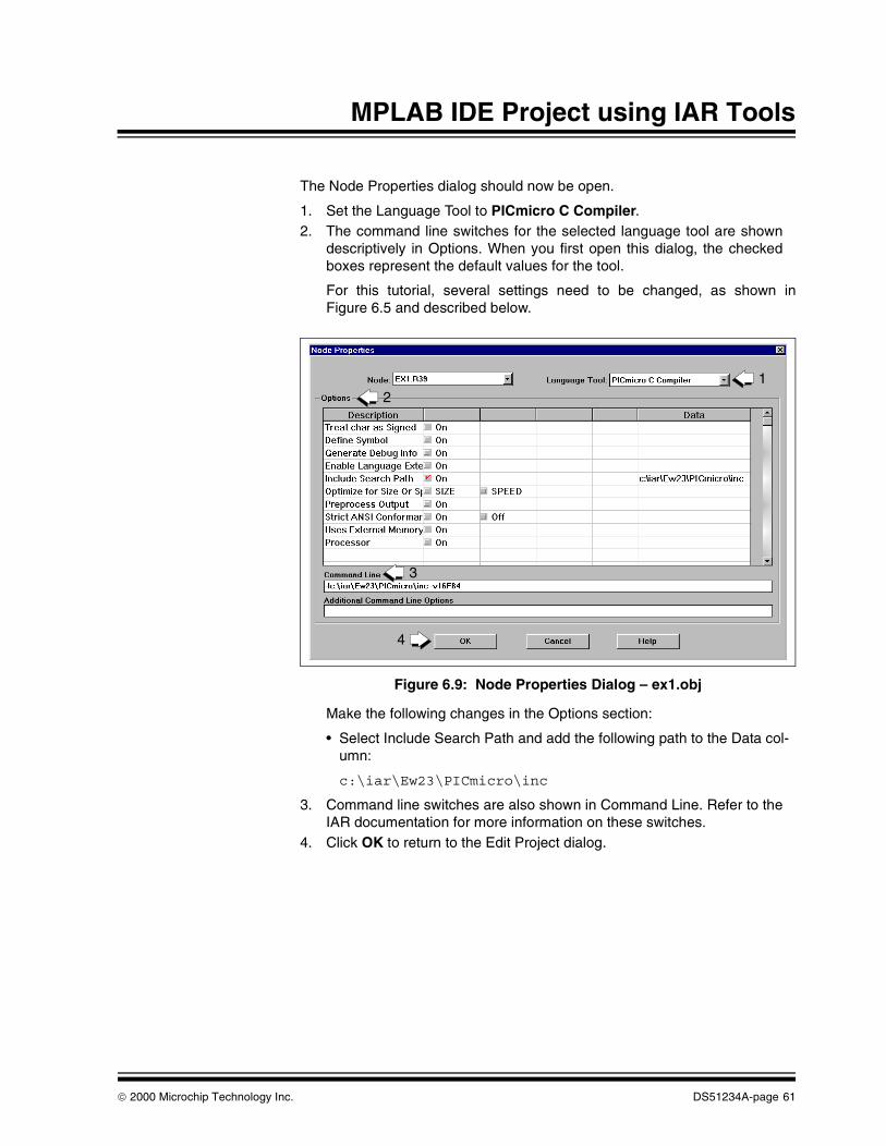
The Node Properties dialog should now be open.
1. Set the Language Tool to PICmicro C Compiler.2. The command line switches for the selected language tool are shown
descriptively in Options. When you first open this dialog, the checkedboxes represent the default values for the tool.
For this tutorial, several settings need to be changed, as shown inFigure 6.5 and described below.
Figure 6.9: Node Properties Dialog – ex1.obj
Make the following changes in the Options section:
• Select Include Search Path and add the following path to the Data col-umn:
c:\iar\Ew23\PICmicro\inc
3. Command line switches are also shown in Command Line. Refer to theIAR documentation for more information on these switches.
4. Click OK to return to the Edit Project dialog.
12
3
4
2000 Microchip Technology Inc. DS51234A-page 61

MPLAB® IDE Project Tutorials
6.11 Add Second Source FileAll node buttons on the Edit Project dialog should be active.
1. Click on Copy Node to open the Copy Node dialog.
Figure 6.10: Edit Project Dialog – Copy Node
In the Copy Node dialog (Figure 6.7);
1. Click on the source file, add.c from the c:\proj1 directory.
This file will be added to the project, with its Node Properties copied fromex1.c.
2. Click OK to return to the Edit Project dialog.
1
DS51234A-page 62 2000 Microchip Technology Inc.

MPLAB IDE Project using IAR Tools
Figure 6.11: Copy Node Dialog – add.c
6.12 Finish Editing ProjectTo finish editing the project;
1. Click OK to close the Edit Project dialog.
Figure 6.12: Edit Project Dialog – Final
2
1
1
2000 Microchip Technology Inc. DS51234A-page 63

MPLAB® IDE Project Tutorials
6.13 Debug and Build ProjectSelect Project > Make Project from the menu to compile the application using the IAR compiler. A Build Results window is created that shows;
1. The command line sent to the compiler, along with other informationspecified in Node Properties
2. Compilation errors3. A compiler error will cause the build to fail, meaning an object file is not
generated, and therefore MPLAB IDE will be unable to find this file.
Figure 6.13: Build Results Window – Build Failed
If you have a build error, double-click on the error in the Build Results window to send you to the line in the source file that contains that error. If the source code file is not open, MPLAB IDE will open the file and then go to the line containing the error.
Now you will fix the error in the source code.
1. Change the "t" to a "z"
Figure 6.14: Source Code with Error
1
2
3
1
DS51234A-page 64 2000 Microchip Technology Inc.

MPLAB IDE Project using IAR Tools
Select File > Save (This step is just good practice, but not necessary, as MPLAB IDE will save the file when doing a build.) Now build the project again by selecting Project > Make Project. The Build Results window should now look different.
1. The command line sent to each tool displayed, along with other informa-tion specified in Node Properties.
2. Memory usage information is provided for each tool.3. Build was successful.
Figure 6.15: Build Results Window – Build Successful (2 Views)
1
3
1
1
2
2
2
2000 Microchip Technology Inc. DS51234A-page 65

MPLAB® IDE Project Tutorials
6.14 More Project InformationThe source code in this tutorial only had one error. However, real untested code would most likely need to be debugged more extensively.
6.14.1 Debug InformationBy selecting COFF Output Format in the Node Properties dialog, the MPLAB IDE has information necessary to help you debug your code.
6.14.2 Project WindowOpen the Window > Project window. This displays various project information, which can be useful to review when debugging.
Figure 6.16: Project Window – ex1.pjt (2 Views)
DS51234A-page 66 2000 Microchip Technology Inc.

MPLAB IDE Project using IAR Tools
Double-clicking on any of the blue file names, you can open these files in the MPLAB IDE. This is ideal for opening files that are not in the project directory (e.g., header .h files), and therefore would require hunting through directory structures to find otherwise.
6.15 Optimization and Other Node PropertiesFor more information on optimization techniques, (e.g., Speed or Size Optimization switches, as well as definitions of other Node Properties switches), please refer to IAR documentation.
2000 Microchip Technology Inc. DS51234A-page 67

MPLAB® IDE Project Tutorials
NOTES:
DS51234A-page 68 2000 Microchip Technology Inc.

®
MPLAB IDE PROJECT TUTORIALSGlossary
IntroductionTo provide a common frame of reference, this glossary defines the terms for several Microchip tools.
HighlightsThis glossary contains terms and definitions for the following tools:
• MPLAB IDE, MPLAB SIM, MPLAB Editor
• MPASM™ assembler, MPLINK™ linker, MPLIB™ librarian
• MPLAB CXX C compilers
• MPLAB ICE emulators
• MPLAB ICD debugger
• PICSTART® Plus, PRO MATE® II programmers
TermsAbsolute Section
A section with a fixed (absolute) address that can not be changed by the linker.
Access RAM (PIC18CXXX Devices Only)
Special general purpose registers on PIC18CXXX devices that allow access regardless of the setting of the bank select bit (BSR).
Alpha Character
Alpha characters are those characters, regardless of case, that are letters of the alphabet: (a, b, …, z, A, B, …, Z).
Alphanumeric
Alphanumeric characters include alpha characters and numbers: (0,1, …, 9).
Application
A set of software and hardware developed by the user, usually designed to be a product controlled by a PICmicro® microcontroller.
Assemble
The process of translating assembly source code into an executable program. This operation is performed by an assembler.
2000 Microchip Technology Inc. DS51234A-page 69

MPLAB® IDE Project Tutorials
Assembler
A language tool that translates a user’s assembly source code (.asm) into machine code. MPASM assembler is Microchip Technology’s assembler tool.
Assembly
A programming language that is once removed from machine language. Machine languages consist entirely of numbers and are almost impossible for humans to read and write. Assembly languages have the same structure and set of commands as machine languages, but they enable a programmer to use names (mnemonics) instead of numbers.
Assigned Section
A section which has been assigned to a target memory block in the linker command file. The linker allocates an assigned section into its specified target memory block.
Breakpoint – Hardware
An event whose execution will cause a halt.
Breakpoint – Software
An address where execution of the firmware will halt. Usually achieved by a special break opcode.
Build
A function that recompiles all the source files for an application.
C
A high level programming language that may be used to generate code for PICmicro microcontrollers, especially high-end device families.
Calibration Memory
A special function register or registers used to hold values for calibration of a PICmicro microcontroller on-board RC oscillator or other device peripherals.
COFF
Common Object File Format. An intermediate file format generated by MPLINK object linker that contains machine code and debugging information.
Command Line Interface
Command line interface refers to executing a program on the DOS™ command line with options.
Executing MPASM assembler with any command line options or just the file name will invoke the assembler. In the absence of any command line options, a prompted input interface (shell) will be executed.
Compile
The process of translating C source code into machine code. This operation is performed by a compiler.
DS51234A-page 70 2000 Microchip Technology Inc.

Compiler
A language tool that translates a user’s C source code into machine code. MPLAB C17 and MPLAB C18 are Microchip Technology’s C compilers for PIC17CXXX and PIC18CXXX devices, respectively.
Configuration Bits
Unique bits programmed to set PICmicro microcontroller modes of operation. A configuration bit may or may not be preprogrammed. These bits are set in the Options > Development Mode dialog for simulators or emulators and in the _ _ CONFIG MPASM directive for programmers.
Control Directives
Control directives in MPASM assembler permit code to be conditionally assembled.
Data Directives
Data directives are those that control MPASM assembler’s allocation of memory and provide a way to refer to data items symbolically; that is, by meaningful names.
Data Memory
General purpose file registers (GPRs) from RAM on the PICmicro device being emulated. The File Register window displays data memory.
Daughter Board
The ICEPIC™ In-Circuit Emulator (Third Party product) uses interchangeable daughter boards to support the different subsets of the PIC16C5X and PIC16CXXX family of PICmicro microcontrollers. The daughter board is a circuit board that connects to the motherboard.
Directives
Directives provide control of the assembler’s operation by telling MPASM assembler how to treat mnemonics, define data, and format the listing file. Directives make coding easier and provide custom output according to specific needs.
Download
Download is the process of sending data from the PC host to another device, such as an emulator, programmer or target board.
EPROM
Erasable Programmable Read Only Memory. A programmable read-only memory that can be erased usually by exposure to ultraviolet radiation.
EEPROM
Electrically Erasable Programmable Read Only Memory. A special type of PROM that can be erased electrically. Data is written or erased one byte at a time. EEPROM retains its contents even when power is turned off.
2000 Microchip Technology Inc. DS51234A-page 71

MPLAB® IDE Project Tutorials
Emulation
The process of executing software loaded into emulation memory as if the firmware resided on the microcontroller device under development.
Emulation Memory
Program memory contained within the emulator.
Emulator
Hardware that performs emulation.
Emulator System
The MPLAB ICE emulator system includes the pod, processor module, device adapter, cables, and MPLAB IDE Software. The ICEPIC In-Circuit Emulator (Third Party product) is another emulator system.
Event
A description of a bus cycle which may include address, data, pass count, external input, cycle type (fetch, R/W), and time stamp. Events are used to describe triggers and breakpoints.
Executable Code
See HEX Code.
Export
Send data out of the MPLAB IDE in a standardized format.
Expressions
Expressions are used in the operand field of MPASM assembler’s source line and may contain constants, symbols, or any combination of constants and symbols separated by arithmetic operators. Each constant or symbol may be preceded by a plus or minus to indicate a positive or negative expression.
Extended Microcontroller Mode(PIC17CXXX and PIC18CXXX Devices Only)
In extended microcontroller mode, on-chip program memory as well as external memory is available. Execution automatically switches to external if the program memory address is greater than the internal memory space of the PIC17CXXX or PIC18CXXX device.
External Input Line (MPLAB ICE only)
An external input signal logic probe line (TRIGIN) for setting an event based upon external signals.
External Linkage
A function or variable has external linkage if it can be accessed from outside the module in which it is defined.
Note: MPASM assembler expressions are evaluated in 32-bit integer math. (Floating point is not currently supported.)
DS51234A-page 72 2000 Microchip Technology Inc.

External RAM (PIC17CXXX and PIC18CXXX Devices Only)
Off-chip Read/Write memory.
External Symbol
A symbol for an identifier which has external linkage.
External Symbol Definition
A symbol for a function or variable defined in the current module.
External Symbol Reference
A symbol which references a function or variable defined outside the current module.
External Symbol Resolution
A process performed by the linker in which external symbol definitions from all input modules are collected in an attempt to update all external symbol references. Any external symbol references which do not have a corresponding definition, cause a linker error to be reported.
File Registers
On-chip general purpose and special function registers.
Flash
A type of EEPROM where data is written or erased in blocks instead of bytes.
FNOP
Forced No Operation. A forced NOP cycle is the second cycle of a two-cycle instruction. Since the PICmicro microcontroller architecture is pipelined, it prefetches the next instruction in the physical address space while it is executing the current instruction. However, if the current instruction changes the program counter, this prefetched instruction is explicitly ignored, causing a forced NOP cycle.
GPR
General Purpose Register. GPR’s may be one section of a file register.
Halt
A function that stops the emulator. Executing Halt is the same as stopping at a breakpoint. The program counter stops, and the user can inspect and change register values, and single step through code.
HEX Code
Executable instructions assembled or compiled from source code into standard hexadecimal format code. Also called executable or machine code. HEX code is contained in a HEX file.
HEX File
An ASCII file containing hexadecimal addresses and values (hex code) suitable for programming a device. This format is readable by a device programmer.
2000 Microchip Technology Inc. DS51234A-page 73

MPLAB® IDE Project Tutorials
High Level Language
A language for writing programs that is of a higher level of abstraction from the processor than assembler code. High level languages (such as C) employ a compiler to translate statements into machine instructions that the target processor can execute.
ICD
In-Circuit Debugger. MPLAB ICD is Microchip Technology’s in-circuit debugger for PIC16F87X devices. MPLAB ICD works with MPLAB IDE.
ICE
In-Circuit Emulator. MPLAB ICE is Microchip Technology’s in-circuit emulator that works with MPLAB IDE. ICEPIC (Third Party product) is another ICE device.
IDE
Integrated Development Environment. An application that has multiple functions for firmware development. The MPLAB IDE integrates a compiler, an assembler, a project manager, an editor, a debugger, a simulator, and an assortment of other tools within one Windows application. A user developing an application can write code, compile, debug, and test an application without leaving the MPLAB IDE desktop.
Identifier
A function or variable name.
Import
Bring data into the MPLAB IDE from an outside source, such as from a HEX file.
Initialized Data
Data which is defined with an initial value. In C,
int myVar=5
defines a variable which will reside in an initialized data section.
Internal Linkage
A function or variable has internal linkage if it can not be accessed from outside the module in which it is defined.
Librarian
A language tool that creates and manipulates libraries. MPLIB librarian is Microchip Technology’s librarian tool.
Library
A library is a collection of relocatable object modules. It is created by assembling multiple source files to object files, and then using the librarian to combine the object files into one library file. A library can be linked with object modules and other libraries to create executable code.
DS51234A-page 74 2000 Microchip Technology Inc.

Link
The process of combining object files and libraries to create executable code. This operation is performed by a linker.
Linker
A language tool that combines object files and libraries to create executable code. Linking is performed by Microchip’s MPLINK linker.
Linker Script Files
Linker script files (.lkr) are the command files of MPLINK linker. They define linker options and describe available memory on the target platform.
Listing Directives
Listing directives are those directives that control the MPASM assembler listing file format. They allow the specification of titles, pagination and other listing control.
Listing File
A listing file is an ASCII text file that shows the machine code generated for each C source statement, assembly instruction, MPASM assembler directive, or macro encountered in a source file.
Local Label
A local label is one that is defined inside a macro with the LOCAL directive. These labels are particular to a given instance of a macro’s instantiation. In other words, the symbols and labels that are declared as local are no longer accessible after the ENDM macro is encountered.
Logic Probes
Up to 14 logic probes can be connected to some Microchip emulators. The logic probes provide external trace inputs, trigger output signal, +5V, and a common ground.
Machine Code
Either object or executable code.
Macro
A collection of assembler instructions that are included in the assembly code when the macro name is encountered in the source code. Macros must be defined before they are used; forward references to macros are not allowed.
All statements following a MACRO directive and prior to an ENDM directive are part of the macro definition. Labels used within the macro must be local to the macro so the macro can be called repetitively.
Macro Directives
Directives that control the execution and data allocation within macro body definitions.
2000 Microchip Technology Inc. DS51234A-page 75

MPLAB® IDE Project Tutorials
Make Project
A command that rebuilds an application, re-compiling only those source files that have changed since the last complete compilation.
MCU
Microcontroller Unit. An abbreviation for microcontroller. Also µC.
Memory Models
Versions of libraries and/or precompiled object files based on a device’s memory (RAM/ROM) size and structure.
Microcontroller
A highly integrated chip that contains all the components comprising a controller. Typically this includes a CPU, RAM, some form of ROM, I/O ports, and timers. Unlike a general-purpose computer, which also includes all of these components, a microcontroller is designed for a very specific task – to control a particular system. As a result, the parts can be simplified and reduced, which cuts down on production costs.
Microcontroller Mode (PIC17CXXX and PIC18CXXX Devices Only)
One of the possible program memory configurations of the PIC17CXXX and PIC18CXXX families of microcontrollers. In microcontroller mode, only internal execution is allowed. Thus, only the on-chip program memory is available in microcontroller mode.
Microprocessor Mode (PIC17CXXX and PIC18CXXX Devices Only)
One of the possible program memory configurations of the PIC17CXXX and PIC18CXXX families of microcontrollers. In microprocessor mode, the on-chip program memory is not used. The entire program memory is mapped externally.
Mnemonics
Instructions that are translated directly into machine code. Mnemonics are used to perform arithmetic and logical operations on data residing in program or data memory of a microcontroller. They can also move data in and out of registers and memory as well as change the flow of program execution. Also referred to as Opcodes.
MPASM Assembler
Microchip Technology’s relocatable macro assembler. MPASM assembler is a DOS or Windows-based PC application that provides a platform for developing assembly language code for Microchip’s PICmicro microcontroller families. Generically, MPASM assember will refer to the entire development platform including the macro assembler and utility functions.
MPASM assembler will translate source code into either object or executable code. The object code created by the assembler may be turned into executable code through the use of the MPLINK linker.
MPLAB CXX
Refers to both the MPLAB C17 and MPLAB C18 C compilers.
DS51234A-page 76 2000 Microchip Technology Inc.

MPLAB ICD
Microchip Technology’s in-circuit debugger for PIC16F87X devices. MPLAB ICD works with MPLAB IDE. The main component of MPLAB ICD is the module. A complete system consists of a module, header, demo board, cables, and MPLAB IDE Software.
MPLAB ICE
Microchip Technology’s in-circuit emulator that works with MPLAB IDE.
MPLAB IDE
The name of the main executable program that supports the IDE with a built-in project manager, editor and simulator (MPLAB SIM) and support for an emulator or debugger. The MPLAB IDE software resides on the PC host. The executable file name is mplab.exe. mplab.exe calls many other files.
MPLAB SIM
Microchip Technology’s simulator that works with MPLAB IDE.
MPLIB Librarian
MPLIB librarian is an object librarian for use with COFF object modules (filename.o) created using either MPASM assembler (mpasm or mpasmwin v2.0) or MPLAB CXX C compilers.
MPLIB librarian will combine multiple object files into one library file. Then the librarian can be used to manipulate the object files within the created library.
MPLINK Linker
MPLINK linker is an object linker for the Microchip MPASM assembler and the Microchip MPLAB C17 or C18 C compilers. MPLINK linker also may be used with the Microchip MPLIB librarian. MPLINK linker is designed to be used with MPLAB IDE, though it does not have to be.
MPLINK linker will combine object files and libraries to create a single executable file.
MPSIM™ Simulator
The DOS version of Microchip’s simulator. MPLAB SIM is the newest simulator from Microchip.
MRU
Most Recently Used. Refers to files and windows available to be selected from MPLAB IDE main pull down menus.
Nesting Depth
The maximum level to which macros can include other macros.
Non Real-Time
Refers to the processor at a breakpoint or executing single step instructions or MPLAB IDE being run in simulator mode.
Node
MPLAB IDE project component.
2000 Microchip Technology Inc. DS51234A-page 77

MPLAB® IDE Project Tutorials
NOP
No Operation. An instruction that has no effect when executed except to advance the program counter.
Object Code
The intermediate code that is produced from the source code after it is processed by an assembler or compiler. Relocatable code is code produced by MPASM assembler or MPLAB C17/C18 C compilers that can be run through MPLINK linker to create executable code. Object code is contained in an object file.
Object File
A module which may contain relocatable code or data and references to external code or data. Typically, multiple object modules are linked to form a single executable output. Special directives are required in the source code when generating an object file. The object file contains object code.
Object File Directives
Directives that are used only when creating an object file.
Off-Chip Memory (PIC17CXXX and PIC18CXXX Devices Only)
Off-chip memory refers to the memory selection option for the PIC17CXXX or PIC18CXXX device where memory may reside on the target board, or where all program memory may be supplied by the Emulator. The Memory tab accessed from Options > Development Mode provides the Off-Chip Memory selection dialog box.
Opcodes
Operational Codes. See Mnemonics.
Operators
Arithmetic symbols, like the plus sign ‘+’ and the minus sign ‘-’, that are used when forming well-defined expressions. Each operator has an assigned precedence.
OTP
One Time Programmable. EPROM devices that are not in windowed packages. Since EPROM needs ultraviolet light to erase its memory, only windowed devices are erasable.
Pass Counter
A counter that decrements each time an event (such as the execution of an instruction at a particular address) occurs. When the pass count value reaches zero, the event is satisfied. You can assign the Pass Counter to break and trace logic, and to any sequential event in the complex trigger dialog.
PC
Personal Computer or Program Counter.
DS51234A-page 78 2000 Microchip Technology Inc.

PC Host
Any IBM or compatible Personal Computer running Windows 3.1x or Windows 95/98, Windows NT, or Windows 2000.
PICmicro® MCUs
PICmicro microcontrollers (MCUs) refers to all Microchip microcontroller families.
PICSTART® Plus Programmer
A device programmer from Microchip. Programs 8, 14, 28, and 40 pin PICmicro microcontrollers. Must be used with MPLAB IDE Software.
Pod
The external emulator box that contains emulation memory, trace memory, event and cycle timers, and trace/breakpoint logic.
Power-on-Reset Emulation
A software randomization process that writes random values in data RAM areas to simulate uninitialized values in RAM upon initial power application.
Precedence
The concept that some elements of an expression are evaluated before others; (i.e., * and / before + and -). In MPASM assembler, operators of the same precedence are evaluated from left to right. Use parentheses to alter the order of evaluation.
Program Counter
A register that specifies the current execution address.
Program Memory
The memory area in a PICmicro microcontroller where instructions are stored. Memory in the emulator or simulator containing the downloaded target application firmware.
Programmer
A device used to program electrically programmable semiconductor devices such as microcontrollers.
Project
A set of source files and instructions to build the object and executable code for an application.
PRO MATE® II Programmer
A device programmer from Microchip. Programs all PICmicro microcontrollers and most memory and KEELOQ® devices. Can be used with MPLAB IDE or stand-alone.
Prototype System
A term referring to a user’s target application, or target board.
2000 Microchip Technology Inc. DS51234A-page 79

MPLAB® IDE Project Tutorials
PWM Signals
Pulse Width Modulation Signals. Certain PICmicro devices have a PWM peripheral.
Qualifier
An address or an address range used by the Pass Counter or as an event before another operation in a complex trigger.
Radix
The number base, hex, or decimal, used in specifying an address and for entering data in the Window > Modify command.
RAM
Random Access Memory (Data Memory).
Raw Data
The binary representation of code or data associated with a section.
Real-Time
When released from the halt state in the emulator or MPLAB ICD mode, the processor runs in real-time mode and behaves exactly as the normal chip would behave. In real-time mode, the real-time trace buffer of MPLAB ICE is enabled and constantly captures all selected cycles, and all break logic is enabled. In the emulator or MPLAB ICD, the processor executes in real-time until a valid breakpoint causes a halt, or until the user halts the emulator.
In the simulator real-time simply means execution of the microcontroller instructions as fast as they can be simulated by the host CPU.
Recursion
The concept that a function or macro, having been defined, can call itself. Great care should be taken when writing recursive macros; it is easy to get caught in an infinite loop where there will be no exit from the recursion.
Relocatable Section
A section whose address is not fixed (absolute). The linker assigns addresses to relocatable sections through a process called relocation.
Relocation
A process performed by the linker in which absolute addresses are assigned to relocatable sections and all identifier symbol definitions within the relocatable sections are updated to their new addresses.
ROM
Read Only Memory (Program Memory).
Run
The command that releases the emulator from halt, allowing it to run the application code and change or respond to I/O in real time.
DS51234A-page 80 2000 Microchip Technology Inc.

Section
An portion of code or data which has a name, size, and address.
SFR
Special Function Register. SFR’s may be one section of a file register.
Shared Section
A section which resides in a shared (non-banked) region of data RAM.
Shell
The MPASM assembler shell is a prompted input interface to the macro assembler. There are two MPASM assembler shells: one for the DOS version and one for the Windows version.
Simulator
A software program that models the operation of PICmicro microcontrollers.
Single Step
This command steps through code, one instruction at a time. After each instruction, MPLAB IDE updates register windows, watch variables, and status displays so you can analyze and debug instruction execution.
You can also single step C compiler source code, but instead of executing single instructions, MPLAB IDE will execute all assembly level instructions generated by the line of the high-level C statement.
Skew
The information associated with the execution of an instruction appears on the processor bus at different times. For example, the executed Opcodes appears on the bus as a fetch during the execution of the previous instruction, the source data address and value and the destination data address appear when the Opcodes is actually executed, and the destination data value appears when the next instruction is executed. The trace buffer captures the information that is on the bus at one instance. Therefore, one trace buffer entry will contain execution information for three instructions. The number of captured cycles from one piece of information to another for a single instruction execution is referred to as the skew.
Skid
When a hardware breakpoint is used to halt the processor, one or more additional instructions may be executed before the processor halts. The number of extra instructions executed after the intended breakpoint is referred to as the skid.
Source Code - Assembly
Source code consists of PICmicro MCU instructions and MPASM assembler directives and macros that will be translated into machine code by an assembler.
2000 Microchip Technology Inc. DS51234A-page 81

MPLAB® IDE Project Tutorials
Source Code - C
A program written in the high-level language called “C” which will be converted into PICmicro MCU machine code by a compiler. Machine code is suitable for use by a PICmicro MCU or Microchip development system product like MPLAB IDE.
Source File - Assembly
The ASCII text file of PICmicro MCU instructions and MPASM assembler directives and macros (source code) that will be translated into machine code by an assembler. It is an ASCII file that can be created using any ASCII text editor.
Source File - C
The ASCII text file containing C source code that will be translated into machine code by a compiler. It is an ASCII file that can be created using any ASCII text editor.
Special Function Registers
Registers that control I/O processor functions, I/O status, timers, or other modes or peripherals.
Stack - Hardware
An area in PICmicro MCU memory where function arguments, return values, local variables, and return addresses are stored; (i.e., a “Push-Down” list of calling routines). Each time a PICmicro MCU executes a CALL or responds to an interrupt, the software pushes the return address to the stack. A return command pops the address from the stack and puts it in the program counter.
The PIC18CXXX family also has a hardware stack to store register values for “fast” interrupts.
Stack - Software
The compiler uses a software stack for storing local variables and for passing arguments to and returning values from functions.
Static RAM or SRAM
Static Random Access Memory. Program memory you can Read/Write on the target board that does not need refreshing frequently.
Status Bar
The Status Bar is located on the bottom of the MPLAB IDE window and indicates such current information as cursor position, development mode and device, and active tool bar.
Step Into
This command is the same as Single Step. Step Into (as opposed to Step Over) follows a CALL instruction into a subroutine.
DS51234A-page 82 2000 Microchip Technology Inc.

Step Over
Step Over allows you to debug code without stepping into subroutines. When stepping over a CALL instruction, the next breakpoint will be set at the instruction after the CALL. If for some reason the subroutine gets into an endless loop or does not return properly, the next breakpoint will never be reached.
The Step Over command is the same as Single Step except for its handling of CALL instructions.
Stimulus
Input to the simulator, (i.e., data generated to exercise the response of simulation to external signals). Often the data is put into the form of a list of actions in a text file. Stimulus may be asynchronous, synchronous (pin), clocked and register.
Stopwatch
A counter for measuring execution cycles.
Symbol
A symbol is a general purpose mechanism for describing the various pieces which comprise a program. These pieces include function names, variable names, section names, file names, struct/enum/union tag names, etc.
Symbols in MPLAB IDE refer mainly to variable names, function names and assembly labels.
System Button
The system button is another name for the system window control. Clicking on the system button pops up the system menu.
2000 Microchip Technology Inc. DS51234A-page 83

MPLAB® IDE Project Tutorials
System Window Control
The system window control is located in the upper left corner of windows and some dialogs. Clicking on this control usually pops up a menu that has the items “Minimize,” “Maximize,” and “Close.” In some MPLAB IDE windows, additional modes or functions can be found.
Figure G1: System Window Control Menu - Watch Window
Target
Refers to user hardware.
Target Application
Firmware residing on the target board.
Target Board
The circuitry and programmable device that makes up the target application.
Target Processor
The microcontroller device on the target application board that is being emulated.
Template
Lines of text that you build for inserting into your files at a later time. The MPLAB Editor stores templates in template files.
Tool Bar
A row or column of icons that you can click on to execute MPLAB IDE functions.
Trace
An emulator or simulator function that logs program execution. The emulator logs program execution into its trace buffer which is uploaded to MPLAB IDE’s trace window.
system window control
DS51234A-page 84 2000 Microchip Technology Inc.

Trace Memory
Trace memory contained within the emulator. Trace memory is sometimes called the trace buffer.
Trigger Output
Trigger output refers to an emulator output signal that can be generated at any address or address range, and is independent of the trace and breakpoint settings. Any number of trigger output points can be set.
Unassigned Section
A section which has not been assigned to a specific target memory block in the linker command file. The linker must find a target memory block in which to allocate an unassigned section.
Uninitialized Data
Data which is defined without an initial value. In C, int myVar; defines a variable which will reside in an uninitialized data section.
Upload
The Upload function transfers data from a tool, such as an emulator or programmer, to the host PC or from the target board to the emulator.
Warning
An alert that is provided to warn you of a situation that would cause physical damage to a device, software file, or equipment.
WatchDog Timer (WDT)
A timer on a PICmicro microcontroller that resets the processor after a selectable length of time. The WDT is enabled or disabled and set up using configuration bits.
Watch Variable
A variable that you may monitor during a debugging session in a watch window.
Watch Window
Watch windows contain a list of watch variables that are updated at each breakpoint.
2000 Microchip Technology Inc. DS51234A-page 85

MPLAB® IDE Project Tutorials
NOTES:
DS51234A-page 86 2000 Microchip Technology Inc.

Index
MPLAB® IDE PROJECT TUTORIALS
Symbols.asm .............................................................. 3, 9.c ............................................................. 3, 9, 49.cod ............................................................... 3, 9.err ................................................ 19, 22, 36, 40.h .............................................................. 18, 32.hex ....................................... 3, 9, 18, 32, 49, 57.lib ................................................................. 3, 9.lst ..................................................... 3, 9, 19, 36.map ................................................. 3, 9, 19, 33.mtc ................................................................... 4.o ...................................................................... 3.obj .................................................................... 9.out ................................................................... 3.pjt ....................................................... 17, 31, 56.r39 ................................................................. 49.s39 ................................................................. 49
AAbsolute Listing ........................................ 25, 43Absolute Section ............................................ 69Access RAM ................................................... 69Add Source File .................................. 20, 34, 59Additional Command Line Options 19, 33, 36, 58apic.exe .......................................................... 47Assembler ........................................ 3, 9, 49, 70Assembler List File ....................... 19, 25, 36, 43Assigned Section ............................................ 70
BBreakpoint, Hardware ..................................... 70Breakpoint, Software ...................................... 70Build Project ....................................... 22, 40, 64Byte Craft ......................................................... 5
CC Compiler ............................................. 3, 9, 49C Programming Language ............................. 70Calibration Memory ........................................ 70CCS .................................................................. 5CD-ROM ............................................................xCode File ...................................................... 3, 9Code, Object .................................................. 78COFF .............................................................. 70COFF File ......................................................... 3COFF Output Format ..................................... 58
Command Line Interface ................................ 70Compiler ......................................................... 71Configuration Bits ........................................... 71Control Directives ........................................... 71Copy Source File ...................................... 37, 62Create New Project ............................. 17, 31, 56Create Source File .......................................... 16Create Source Files .................................. 30, 54Customer Notification Service .........................xiiCustomer Support ...........................................xiv
DData Directives ............................................... 71Data, Memory ................................................. 71Data, Uninitialized ........................................... 85Debug Information .............................. 24, 42, 66Directives ........................................................ 71
Control ...................................................... 71Data .......................................................... 71Listing ....................................................... 75Macro ....................................................... 76Object File ................................................ 78
Display Complete Memory Usage .................. 33Display Memory Usage ................................... 19Documentation
Conventions .............................................viiiLayout .......................................................viiNumbering Conventions ............................ ixUpdates ..................................................... ix
EEdit Project ......................................... 18, 32, 57Emulator ......................................................... 72Environment Variables ............................ 4, 9, 49Error File ....................................... 19, 22, 36, 40Error/Warning Formatting ................................. 9Executable Code ............................................ 72Executable Files ..................................... 3, 9, 49Extended Microcontroller Mode ...................... 72External RAM .................................................. 73
FFAKELOCAL ........................... 19, 26, 33, 36, 44File, Listing ...................................................... 75
2000 Microchip Technology Inc. DS51234A-page 87

MPLAB® IDE Project Tutorials
GGenerate Debug Info ..........................19, 33, 36Glossary ..........................................................69
HHEX Code .......................................................73HEX File ................................3, 9, 18, 32, 49, 57HI-TECH .......................................................4, 7
IIAR ..............................................................4, 47iara.exe ...........................................................47iari.exe ............................................................47iarl.exe ............................................................47iccpic.exe ........................................................47ICD ..................................................................74ICE ..................................................................74IDE ..................................................................74Include Current Search Path ....................18, 32Include Search Path .................................58, 61Index ...............................................................87Initialization Code .............................................3Initialized Data ................................................74Install Lanugage Tools ............................4, 9, 49Integrating Other Tools into MPLAB .................4Internet Address .............................................. xiInterrupt Service Routines ................................3
Llibr.exe ..............................................................9Librarian ............................................3, 9, 49, 74Library
Files ..................................................3, 9, 49Linker ..............................................................75Linker Script Files ...........................................75Listing Directives .............................................75Listing File ...............................................3, 9, 75Local Label .....................................................75Logic Probes ...................................................75
MMacro ..............................................................75Macro Directives .............................................76Map File ................................3, 9, 19, 24, 33, 42MCU ................................................................76Memory
Calibration ................................................70Data ..........................................................71Program ....................................................79Trace ........................................................85
Memory Models ..............................................76
Microchip Internet Web Site ............................. xiMicrocontroller Mode .......................................76microEngineering Labs .....................................5Microprocessor Mode ......................................76Mnemonics ......................................................76Mode
Extended Microcontroller ..........................72Microcontroller ..........................................76Microprocessor .........................................76
Models, Memory ..............................................76MPASM Assembler ...................................70, 76MPLAB CXX ....................................................77MPLAB ICD .....................................................77MPLAB ICE .....................................................77MPLAB IDE .....................................................77MPLAB SIM .....................................................77MPLIB Librarian ........................................74, 77MPLINK Linker ..........................................75, 77
NNode Properties, Other .......................27, 46, 67Node Properties, Source ...........................35, 60Node Properties, Target ......................19, 33, 58
OObject Code ....................................................78Object File Directives ......................................78Object Files .............................................3, 9, 49Object Files, Precompiled .......................3, 9, 49Off-Chip Memory .............................................78Opcodes ..........................................................78Operators ........................................................78Optimization ........................................27, 46, 67
PPass Counter ..................................................79PC ...................................................................79PCB, PCH, PCM ...............................................5PICBASIC™ Compiler .......................................5PICC™ Tools ...........................................4, 7, 11PICC Lite™ Tools ....................................4, 7, 12picc.exe .......................................................7, 11picl.exe ........................................................7, 12PICmicro® MCU ........................................79, 82PICSTART® Plus ............................................79Precedence .....................................................79Preliminary Setup of MPLAB ...................3, 9, 49PRO MATE® II ................................................80Program Counter .............................................79Program Memory ............................................79
DS51234A-page 88 2000 Microchip Technology Inc.

Index
Programmer ................................................... 79Project ............................................................ 79
HI-TECH PICC Tools Overview ................. 7IAR Tools Overview ................................. 47More Information .......................... 24, 42, 66Multiple Source File using PICC Tools .... 29Relationships Diagram ... 2, 8, 15, 29, 48, 54Single Source File using PICC Tools ....... 15Third Party Tools Overview ....................... 1Using IAR Tools ....................................... 53
Project Window .................................. 27, 45, 66
QQualifier .......................................................... 80
RRadix .............................................................. 80RAM ......................................................... 71, 80RAM, Access .................................................. 69RAM, External ................................................ 73Reading, Recommended ...................................xReal-Time ....................................................... 80Register Definitions .......................................... 3Relocatable Section ....................................... 80ROM ......................................................... 79, 81
SSection ........................................................... 81
Absolute ................................................... 69Assigned .................................................. 70Relocatable .............................................. 80Shared ..................................................... 81Unassigned .............................................. 85
Set Development Mode ...................... 17, 31, 55Setup Path ...................................................... 49Shared Section ............................................... 81Simulator ........................................................ 81Single Step ..................................................... 81Skew ............................................................... 81Skid ................................................................ 81Source Code
Assembly ................................... 3, 9, 49, 82C ................................................ 3, 9, 49, 82
Source Node Properties ........................... 35, 60Stack
Hardware ................................................. 82Software ................................................... 82
Start Up Code ................................................... 3Stimulus .......................................................... 83Symbol ........................................................... 83
Symbol List ............................................... 26, 44System Button ................................................ 84System Window Control ................................. 84
TTarget ............................................................. 84Target Node Properties ...................... 19, 33, 58TLxxxx.INI ......................................................... 4Trace .............................................................. 84
Memory .................................................... 85Troubleshooting ................................................ x
UUnassigned Section ........................................ 85Uninitialized Data ............................................ 85
WWarranty Registration ...................................... ixWatch Window ................................................ 85WWW Address ................................................ xi
Xxlib.exe ........................................................... 49xlink.exe .......................................................... 47
2000 Microchip Technology Inc. DS51234A-page 89

Information contained in this publication regarding device applications and the like is intended through suggestion only and may be superseded byupdates. It is your responsibility to ensure that your application meets with your specifications. No representation or warranty is given and no liability isassumed by Microchip Technology Incorporated with respect to the accuracy or use of such information, or infringement of patents or other intellectualproperty rights arising from such use or otherwise. Use of Microchip’s products as critical components in life support systems is not authorized except withexpress written approval by Microchip. No licenses are conveyed, implicitly or otherwise, except as maybe explicitly expressed herein, under any intellec-tual property rights. The Microchip logo and name are registered trademarks of Microchip Technology Inc. in the U.S.A. and other countries. All rightsreserved. All other trademarks mentioned herein are the property of their respective companies.
DS51234A-page 90 2000 Microchip Technology Inc.
All rights reserved. © 2000 Microchip Technology Incorporated. Printed in the USA. 12/00 Printed on recycled paper.
AMERICASCorporate Office2355 West Chandler Blvd.Chandler, AZ 85224-6199Tel: 480-792-7200 Fax: 480-792-7277Technical Support: 480-792-7627Web Address: http://www.microchip.comRocky Mountain2355 West Chandler Blvd.Chandler, AZ 85224-6199Tel: 480-792-7966 Fax: 480-792-7456
Atlanta500 Sugar Mill Road, Suite 200BAtlanta, GA 30350Tel: 770-640-0034 Fax: 770-640-0307Boston2 Lan Drive, Suite 120Westford, MA 01886Tel: 978-692-3848 Fax: 978-692-3821Chicago333 Pierce Road, Suite 180Itasca, IL 60143Tel: 630-285-0071 Fax: 630-285-0075Dallas4570 Westgrove Drive, Suite 160Addison, TX 75001Tel: 972-818-7423 Fax: 972-818-2924DaytonTwo Prestige Place, Suite 130Miamisburg, OH 45342Tel: 937-291-1654 Fax: 937-291-9175DetroitTri-Atria Office Building 32255 Northwestern Highway, Suite 190Farmington Hills, MI 48334Tel: 248-538-2250 Fax: 248-538-2260Los Angeles18201 Von Karman, Suite 1090Irvine, CA 92612Tel: 949-263-1888 Fax: 949-263-1338New York150 Motor Parkway, Suite 202Hauppauge, NY 11788Tel: 631-273-5305 Fax: 631-273-5335San JoseMicrochip Technology Inc.2107 North First Street, Suite 590San Jose, CA 95131Tel: 408-436-7950 Fax: 408-436-7955Toronto6285 Northam Drive, Suite 108Mississauga, Ontario L4V 1X5, CanadaTel: 905-673-0699 Fax: 905-673-6509
ASIA/PACIFICChina - BeijingMicrochip Technology Beijing OfficeUnit 915New China Hong Kong Manhattan Bldg.No. 6 Chaoyangmen Beidajie Beijing, 100027, No. ChinaTel: 86-10-85282100 Fax: 86-10-85282104China - ShanghaiMicrochip Technology Shanghai OfficeRoom 701, Bldg. BFar East International PlazaNo. 317 Xian Xia RoadShanghai, 200051Tel: 86-21-6275-5700 Fax: 86-21-6275-5060Hong KongMicrochip Asia PacificRM 2101, Tower 2, Metroplaza223 Hing Fong RoadKwai Fong, N.T., Hong KongTel: 852-2401-1200 Fax: 852-2401-3431IndiaMicrochip Technology Inc.India Liaison OfficeDivyasree Chambers1 Floor, Wing A (A3/A4)No. 11, O’Shaugnessey RoadBangalore, 560 025, IndiaTel: 91-80-2290061 Fax: 91-80-2290062JapanMicrochip Technology Intl. Inc.Benex S-1 6F3-18-20, ShinyokohamaKohoku-Ku, Yokohama-shiKanagawa, 222-0033, JapanTel: 81-45-471- 6166 Fax: 81-45-471-6122KoreaMicrochip Technology Korea168-1, Youngbo Bldg. 3 FloorSamsung-Dong, Kangnam-KuSeoul, KoreaTel: 82-2-554-7200 Fax: 82-2-558-5934
ASIA/PACIFIC (continued)SingaporeMicrochip Technology Singapore Pte Ltd.200 Middle Road#07-02 Prime CentreSingapore, 188980Tel: 65-334-8870 Fax: 65-334-8850TaiwanMicrochip Technology Taiwan11F-3, No. 207Tung Hua North RoadTaipei, 105, TaiwanTel: 886-2-2717-7175 Fax: 886-2-2545-0139
EUROPEDenmarkMicrochip Technology Denmark ApSRegus Business CentreLautrup hoj 1-3Ballerup DK-2750 DenmarkTel: 45 4420 9895 Fax: 45 4420 9910FranceArizona Microchip Technology SARLParc d’Activite du Moulin de Massy43 Rue du Saule TrapuBatiment A - ler Etage91300 Massy, FranceTel: 33-1-69-53-63-20 Fax: 33-1-69-30-90-79GermanyArizona Microchip Technology GmbHGustav-Heinemann Ring 125D-81739 Munich, GermanyTel: 49-89-627-144 0 Fax: 49-89-627-144-44ItalyArizona Microchip Technology SRLCentro Direzionale Colleoni Palazzo Taurus 1 V. Le Colleoni 120041 Agrate BrianzaMilan, Italy Tel: 39-039-65791-1 Fax: 39-039-6899883United KingdomArizona Microchip Technology Ltd.505 Eskdale RoadWinnersh TriangleWokingham Berkshire, England RG41 5TUTel: 44 118 921 5869 Fax: 44-118 921-5820
10/01/00
WORLDWIDE SALES AND SERVICE
Microchip received QS-9000 quality system certification for its worldwide headquarters, design and wafer fabrication facilities in Chandler and Tempe, Arizona in July 1999. The Company’s quality system processes and procedures are QS-9000 compliant for its PICmicro® 8-bit MCUs, KEELOQ® code hopping devices, Serial EEPROMs and microperipheral products. In addition, Microchip’s quality system for the design and manufacture of development systems is ISO 9001 certified.