
MPC-3000 Field Technical Manual
33
MPC-3000 Field Technical Manual Spectra Watermakers, Inc. 20 Mariposa Road, San Rafael, CA 94901 Phone 415-526-2780 Fax 415-526-2787 E-mail: [email protected] www.spectrawatermakers.com Rev. 08-11-05
Transcript of MPC-3000 Field Technical Manual

MPC-3000 Field Technical Manual
Spectra Watermakers, Inc. 20 Mariposa Road, San Rafael, CA 94901 Phone 415-526-2780 Fax 415-526-2787
E-mail: [email protected] www.spectrawatermakers.com
Rev. 08-11-05

2
3
Spectra Watermakers MPC-3000 Field Technical Manual
Revision A25 08-16-05
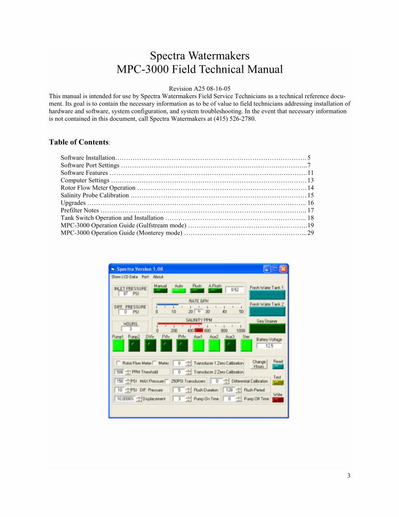
This manual is intended for use by Spectra Watermakers Field Service Technicians as a technical reference docu-ment. Its goal is to contain the necessary information as to be of value to field technicians addressing installation of hardware and software, system configuration, and system troubleshooting. In the event that necessary information is not contained in this document, call Spectra Watermakers at (415) 526-2780. Table of Contents: Software Installation……………………………………………………………………………. 5 Software Port Settings ………………………………………………………………………….. 7 Software Features ………………………………………………………………………………. 11 Computer Settings ……………………………………………………………………………… 13 Rotor Flow Meter Operation …………………………………………………………………… 14 Salinity Probe Calibration ……………………………………………………………………… 15 Upgrades ……………………………………………………………………………………….. 16 Prefilter Notes ………………………………………………………………………………….. 17 Tank Switch Operation and Installation ……………………………………………………….. 18 MPC-3000 Operation Guide (Gulfstream mode) ………………………………………………. 19 MPC-3000 Operation Guide (Monterey mode) ………………………………………………... 29

4

5
Software Installation from CD:
1) Insert the Spectra Watermakers CD-ROM into the computer’s CD-ROM drive. 2) Using “My Computer” or Windows Explorer, locate and double-click the “setup.exe” file on the CD-
ROM drive. This will begin the installation process. Follow the on-screen instructions. 3) When the software is installed, it will open from the “Start → Programs” menu 4) Before using the software, your MPC-3000 circuit board must be connected to your computer’s COM
port using a standard RS-232 serial cable (NO crossovers on cable). 12V or 24V DC power must be applied to the MPC-3000 board, and the board must be on before the software can communicate with it. The software may not run if these steps are not taken. You will get an error message if there is a COM port conflict.
5) If you have no serial port available, you may purchase a USB-to-serial port adapter. Once the soft-ware has been installed, open the directory where it was installed, locate and double-click the “spectra.exe” file to run the program.
To reset the COM port, follow the directions beginning on page 5. When the software is opened and the watermaker is connected, you will see this window:

6

7
MPC Software Port Settings
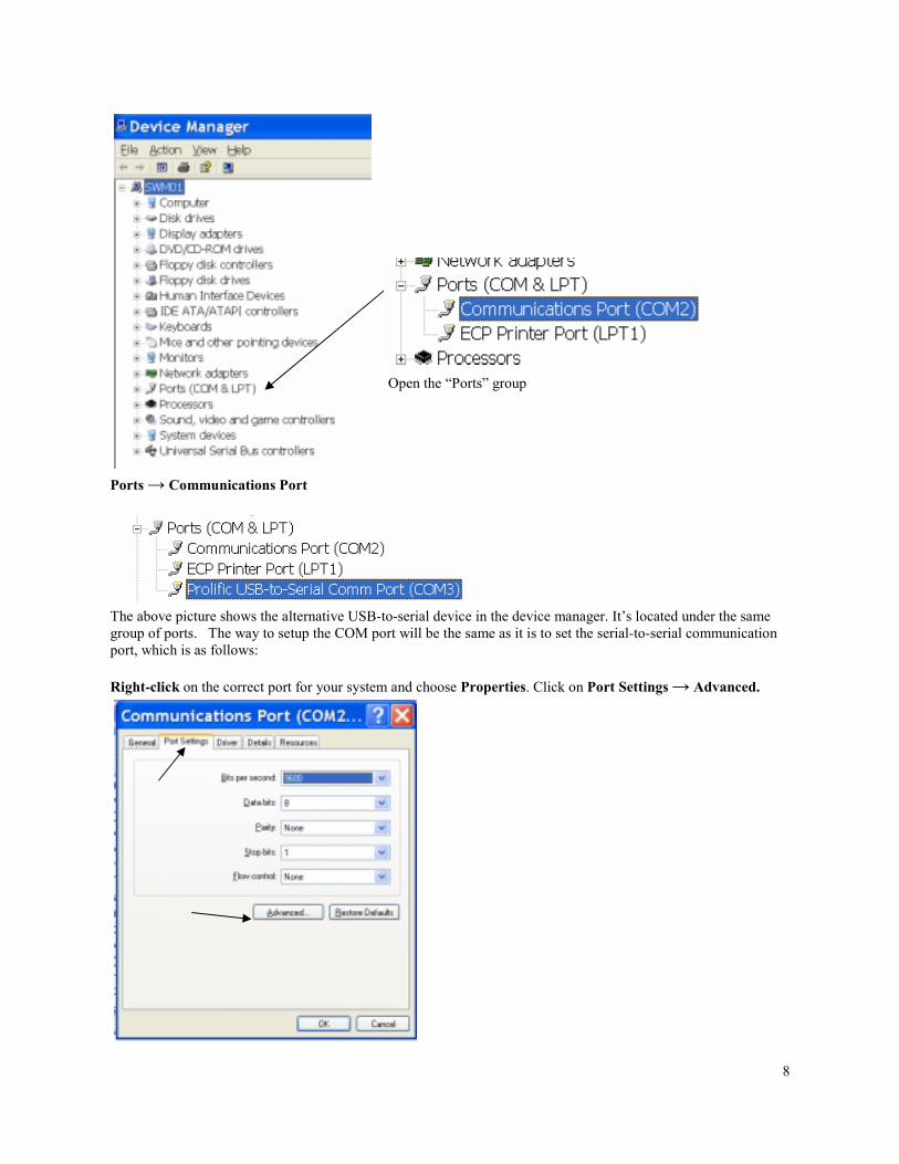
Start → Settings → Control Panel → System
Choose the “Hardware” tab and click on “Device Manager”
8
Ports → Communications Port
The above picture shows the alternative USB-to-serial device in the device manager. It’s located under the same group of ports. The way to setup the COM port will be the same as it is to set the serial-to-serial communication port, which is as follows: Right-click on the correct port for your system and choose Properties. Click on Port Settings → Advanced.
Open the “Ports” group
9
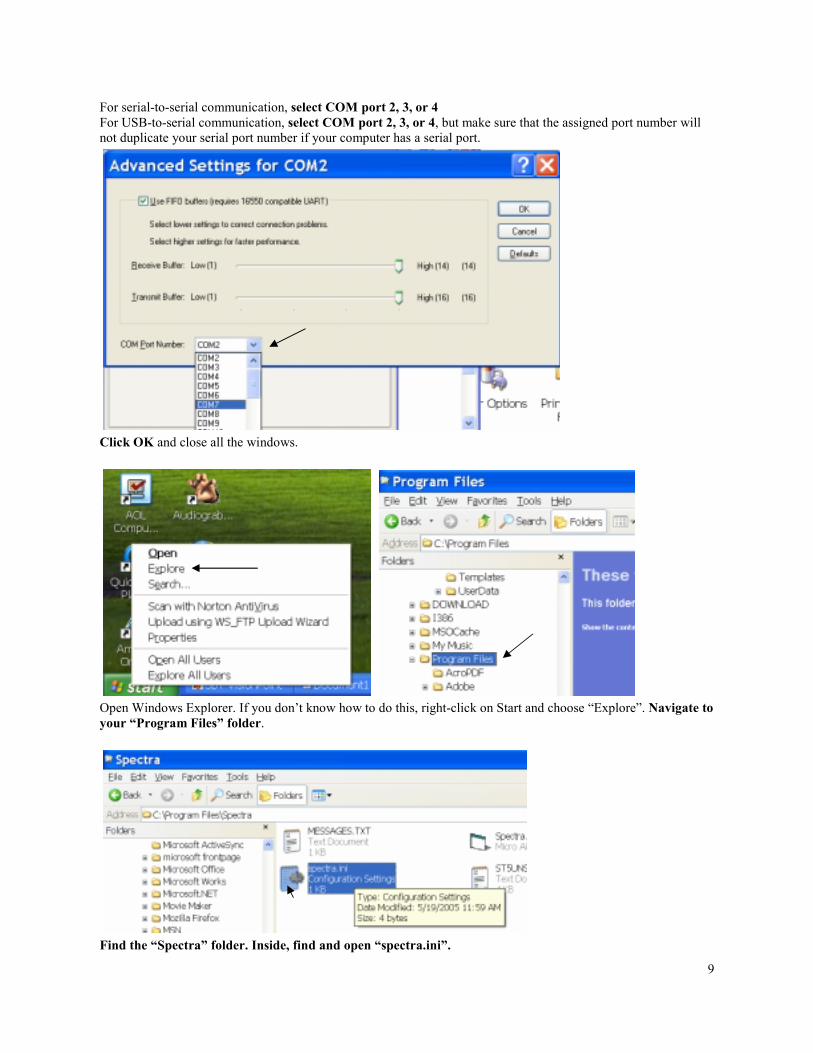
For serial-to-serial communication, select COM port 2, 3, or 4 For USB-to-serial communication, select COM port 2, 3, or 4, but make sure that the assigned port number will not duplicate your serial port number if your computer has a serial port.
Click OK and close all the windows.
Open Windows Explorer. If you don’t know how to do this, right-click on Start and choose “Explore”. Navigate to your “Program Files” folder.
Find the “Spectra” folder. Inside, find and open “spectra.ini”.

10
Change the number on the first row to be the same as the number of the COM port you chose, then save and close the file.
Now we’re ready to run the software. Start → Programs → Spectra
The software should now run properly.

11
Software Features: 1) Show LCD Data: Clicking on this field will change the settings window to allow you to change what
is displayed on the control Panel. This feature can allow you to customize the display for another language if desired. Select the line to change, enter a new caption for that line, and hit change. There are limits to how many characters are allowed. Contact the factory before making changes in this window.
2) Port: Allows you to select which COM port on your computer will communicate with the MPC-3000 board via RS-232 serial cable.
3) Inlet Pressure: Displays real-time system pressure at the prefilter inlet.
4) Diff Pressure: Displays real-time pressure differential across the two prefilters.
5) Hours: Displays total hours the MPC-3000 has been run.
6) Manual, Auto, Flush, A.Flush, Timer: These are simply display lights to show which mode the
MPC-3000 is currently in. The timer will display any countdown time for the current mode.
7) Rate GPH: Real-time meter showing gallons or liters per-hour product.
8) Salinity: Real-time meter showing salinity measurement of product water in parts-per-million.
9) Fresh Water Tank 1, Fresh Water Tank 2, Sea Strainer: Display lights to indicate state of tank switches and sea strainer condition.
10) Pump1, Pump2, Dvlv, Fvlv, Pvlv, Aux1, Aux2, Aux3, Ster: Display lights to indicate output states
of the MPC board.
11) Battery Voltage: Displays current DC voltage applied to the MPC board.
12) Rotor Flow Meter: Check this box if a rotor flow meter is to be used. Refer to “Rotor Flow Meter Operation” section later in this manual.
13) Metric: Check box to change display units of measurement from English to metric. (Can also be
accomplished by pressing and holding “Alarm/Disp” on the LCD display for 5 seconds.)
14) PPM Threshold: Default at 500 ppm, Sets the reject salinity level of product water. This is currently factory set at 750 PPM. (Above 750ppm product is rejected, below 750ppm it is accepted and di-verted to holding tank).
15) PSI Max Pressure: Used to set the maximum allowable system pressure, measured at prefilters.
Typically 150psi for Newport400 systems, and 250psi for Monterey/1000 gallon systems.
16) PSI DIF. Pressure: Used to set the differential cutoff pressure; the two pressure sensors at the prefil-ter are used to measure any difference in pressure between the two prefilters, possibly caused by a dirty filter. Differential Cutoff will stop system and sound alarm if differential pressure exceeds set maximum. Typically set to 10 psi.
12
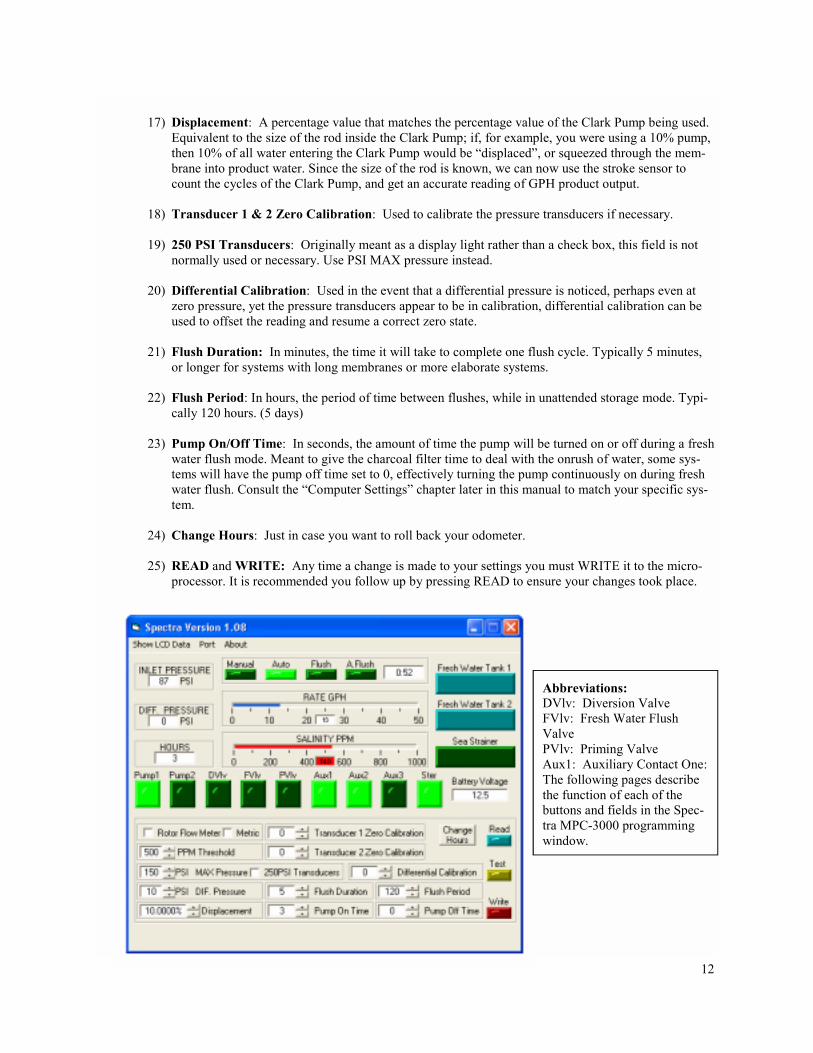
17) Displacement: A percentage value that matches the percentage value of the Clark Pump being used.
Equivalent to the size of the rod inside the Clark Pump; if, for example, you were using a 10% pump, then 10% of all water entering the Clark Pump would be “displaced”, or squeezed through the mem-brane into product water. Since the size of the rod is known, we can now use the stroke sensor to count the cycles of the Clark Pump, and get an accurate reading of GPH product output.
18) Transducer 1 & 2 Zero Calibration: Used to calibrate the pressure transducers if necessary.
19) 250 PSI Transducers: Originally meant as a display light rather than a check box, this field is not
normally used or necessary. Use PSI MAX pressure instead.
20) Differential Calibration: Used in the event that a differential pressure is noticed, perhaps even at zero pressure, yet the pressure transducers appear to be in calibration, differential calibration can be used to offset the reading and resume a correct zero state.
21) Flush Duration: In minutes, the time it will take to complete one flush cycle. Typically 5 minutes,
or longer for systems with long membranes or more elaborate systems.
22) Flush Period: In hours, the period of time between flushes, while in unattended storage mode. Typi-cally 120 hours. (5 days)
23) Pump On/Off Time: In seconds, the amount of time the pump will be turned on or off during a fresh
water flush mode. Meant to give the charcoal filter time to deal with the onrush of water, some sys-tems will have the pump off time set to 0, effectively turning the pump continuously on during fresh water flush. Consult the “Computer Settings” chapter later in this manual to match your specific sys-tem.
24) Change Hours: Just in case you want to roll back your odometer.
25) READ and WRITE: Any time a change is made to your settings you must WRITE it to the micro-
processor. It is recommended you follow up by pressing READ to ensure your changes took place.
Abbreviations: DVlv: Diversion Valve FVlv: Fresh Water Flush Valve PVlv: Priming Valve Aux1: Auxiliary Contact One: The following pages describe the function of each of the buttons and fields in the Spec-tra MPC-3000 programming window.
13
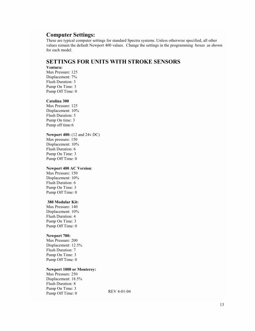
Computer Settings: These are typical computer settings for standard Spectra systems. Unless otherwise specified, all other values remain the default Newport 400 values. Change the settings in the programming boxes as shown for each model. SETTINGS FOR UNITS WITH STROKE SENSORS Ventura: Max Pressure: 125 Displacement: 7% Flush Duration: 3 Pump On Time: 3 Pump Off Time: 0 Catalina 300 Max Pressure: 125 Displacement: 10% Flush Duration: 5 Pump On time: 3 Pump off time:6 Newport 400: (12 and 24v DC) Max pressure: 150 Displacement: 10% Flush Duration: 6 Pump On Time: 3 Pump Off Time: 0 Newport 400 AC Version: Max Pressure: 150 Displacement: 10% Flush Duration: 6 Pump On Time: 3 Pump Off Time: 0 380 Modular Kit: Max Pressure: 140 Displacement: 10% Flush Duration: 4 Pump On Time: 3 Pump Off Time: 0 Newport 700: Max Pressure: 200 Displacement: 12.5% Flush Duration: 7 Pump On Time: 3 Pump Off Time: 0 Newport 1000 or Monterey: Max Pressure: 250 Displacement: 18.5% Flush Duration: 8 Pump On Time: 3 Pump Off Time: 0 REV 4-01-04

14
Rotor Flow Meter: We are currently shipping our watermakers with Gems brand rotor flow meters. A rotor flow meter is a pinwheel device with a hall-effect sensor built in, installed in line with product water output from the reverse osmosis (RO) membrane. When water passes through the meter, it spins the pinwheel; the hall-effect sensor picks up the motions of the pinwheel and sends the frequency of the spinning pinwheel to the MPC board. The MPC board then calculates, based on a “meter constant”, the gallon-per-minute output of product water, thereby eliminating the need for a stroke sensor. The rotor flow meter uses the same three terminals on the MPC-3000 circuit board as the stroke sensor. When programming a watermaker with a rotor flow meter, the “Rotor Flow Meter” check box must be checked. The “Displacement” field will then read a default constant which can be adjusted up or down to calibrate the product flow reading on the display. Start with a setting of 14,000. Run the watermaker with the product going into a meas-ured container instead of the tank and time the product flow. Adjust the roto flow con-stant up or down until the display reads the same as the actual measured flow.

15
Salinity Probe Calibration: Salinity is a measurement of total dissolved solids in liquid (TDS). These solids will conduct electric-ity to varying degrees. A special probe is used, with two electrical contacts in it, to determine the resis-tance to the flow of electricity in the liquid. In the Spectra Watermakers’ systems, the salinity probe is located just before the diversion valve, at the output of the RO membrane. This way we can look at the salinity level of the product water before deciding to either reject the water or accept it and divert it into the holding tank. The salinity level in parts-per-million (PPM) can be seen either through the salinity meter in the soft-ware or by adding a jumper to the MPC board in the “calibrate” position. The salinity can then be seen on the LCD display (rather than a bar graph). After adding the jumper, it may be necessary to cycle through the different LCD displays until the display reads “Salinity.” Procedure: 1. Locate the calibrate jumper location on the MPC-3000 Board. Jump the terminals. 2. Start the system. After the salinity stabilizes, test the product water with a calibrated hand held
tester. 3. Locate the MPC calibration trimmer potentiometer on the board below the salinity probe jack.
Adjust until the display PPM matches the PPM reading from the hand held salinity monitor. Turn-ing the trim pot clockwise will lower the salinity reading, and counter-clockwise will raise it.
4. Shut the system down and disconnect the jumper on the MPC board. If a hand held meter is not available, you can remove the probe and dip it into a known calibrated solu-tion. This can be obtained from Spectra.

16
Upgrades: The version of microprocessor software used in the control is shown on the display whenever the wa-termaker is in standby mode (powered up but not in run or auto flush mode. It is possible to upgrade Newport series watermakers through the different versions of software/firmware. Outlined below are some of the requirements and procedures necessary for upgrade. NOTE: It is very important to use the correct version of programming software for the version of mi-croprocessor software. B29 The current software version. It fixed a pressure sensor calibration reset on start up error present in A28 and A29 if you are experiencing nuisance shutdowns from “High Pressure” or “Service Prefilter” alarms on systems using A28 or A29. A29 Modified salinity temperature calibration circuit A28 Removed system stalled shutdown during purge A27 Fixed a glitch in the metric pressure reading display A26 Added rotor flow A25 Adds automatic pressure relief control for the watermachine series and fixes a few small glitches. Uses version 1.08 software A24 Minor fixes from A23 include enabling the Start/Stop button to halt the system in ALL modes of operation, and to display when the tanks are full when the system has shut down, if applicable. Soft-ware for A24 is version 1.08, upgrading to A24 is a microprocessor change. A23 is a test revision firmware. Features added include voltage cutoff spread increase, Auto-fill mode, and some display improvements. A23 is quite functional, but a few improvements have been made to make the system more user-friendly. Software for A23 is version 1.06. Upgrading to A23 is a microprocessor change. A21 was the standard working firmware for a while, with no-frills, solid, working code. Some prob-lems that might be encountered with A21 are that the high and low voltage cutoffs are not spread out far enough– you are more likely to see high and low voltage alarm problems because of it. Software for A21 is version 1.03. Upgrading from A21 to A23 is a microprocessor change. A19 to A21 require a minor wiring change in 12 and 24 volt systems. When upgrading from A19 soft-ware, call the factory for instructions. Upgrading an A19 1000gal/Monterey/AC system to A21/A23 requires only a new microprocessor- no wiring changes are necessary.
17
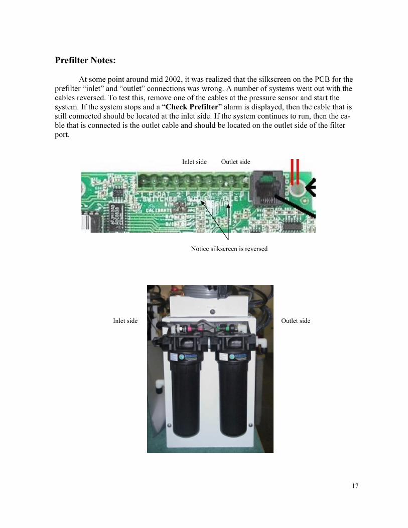
Prefilter Notes: At some point around mid 2002, it was realized that the silkscreen on the PCB for the prefilter “inlet” and “outlet” connections was wrong. A number of systems went out with the cables reversed. To test this, remove one of the cables at the pressure sensor and start the system. If the system stops and a “Check Prefilter” alarm is displayed, then the cable that is still connected should be located at the inlet side. If the system continues to run, then the ca-ble that is connected is the outlet cable and should be located on the outlet side of the filter port.
Inlet side Outlet side
Notice silkscreen is reversed
Inlet side Outlet side

18
Tank Switch Installation and Operation: There are two sets of terminals on the MPC-3000 PCB that can be used in four different con-figurations to automatically start and stop the watermaker, or to automatically stop the water-maker when the tank(s) are full without the “Auto Start” feature. These terminals are on the green ten-pin connector and are labeled “Float Switch 1” and “Float Switch 2.” Float Switch 1 is the tank full switch, and Float Switch 2 is the tank empty switch. If the unit is wired for both auto-start and auto-stop, it can be put into auto-fill mode by pushing and holding the “Auto Run” switch on the MPC-3000 display. In this mode, the watermaker will start whenever the water level drops below the tank empty switch, thus opening it (breaking the circuit). When the tank fills up and both the tank full and tank empty switches have remained closed for two minutes, the watermaker will shut down and flush itself. The wa-ter maker will then start back up when the water level drops below the tank empty switch and it remains open for 2 minutes. This configuration allows for completely automatic operation. If the watermaker does not need to start up within five days, it will automatically do a fresh water flush. Auto-fill mode can be ended by pushing the “Stop” button or the “Auto Flush” button. If the watermaker is in auto-run mode it can be put into auto-fill mode without stopping it by holding down the “Auto Run” button. If the owner prefers to install the automatic shutoff feature without the automatic start up op-tion, only the tank full switch is used. A jumper must be placed between the tank empty termi-nals (Float Switch 2) in place of the tank empty switch, because the watermaker will only shut down if both sets of terminals are closed. To use this mode, the watermaker must be started up with the “Stop/Start” button or the “Auto Run” button. After the unit starts up, press and hold the “Auto Run” button until the display reads “Auto Fill Mode”. The watermaker will fill the tank and automatically enter auto-flush mode. It is possible to use the auto-fill feature with two tanks. A double-throw electrical switch must be installed in a convenient location. If only the single tank full switch is installed in each tank, connect the wire from Float Switch 1, terminal 1 to the common on the switch and run separate wires from the switch to each tank switch. The second wires can both be run to Float Switch 1, terminal 2. If you are using two switches in each tank, you will need a double-pole, double-throw switch.
19
Spectra MPC-3000 Operation Guide
Gulfstream Mode
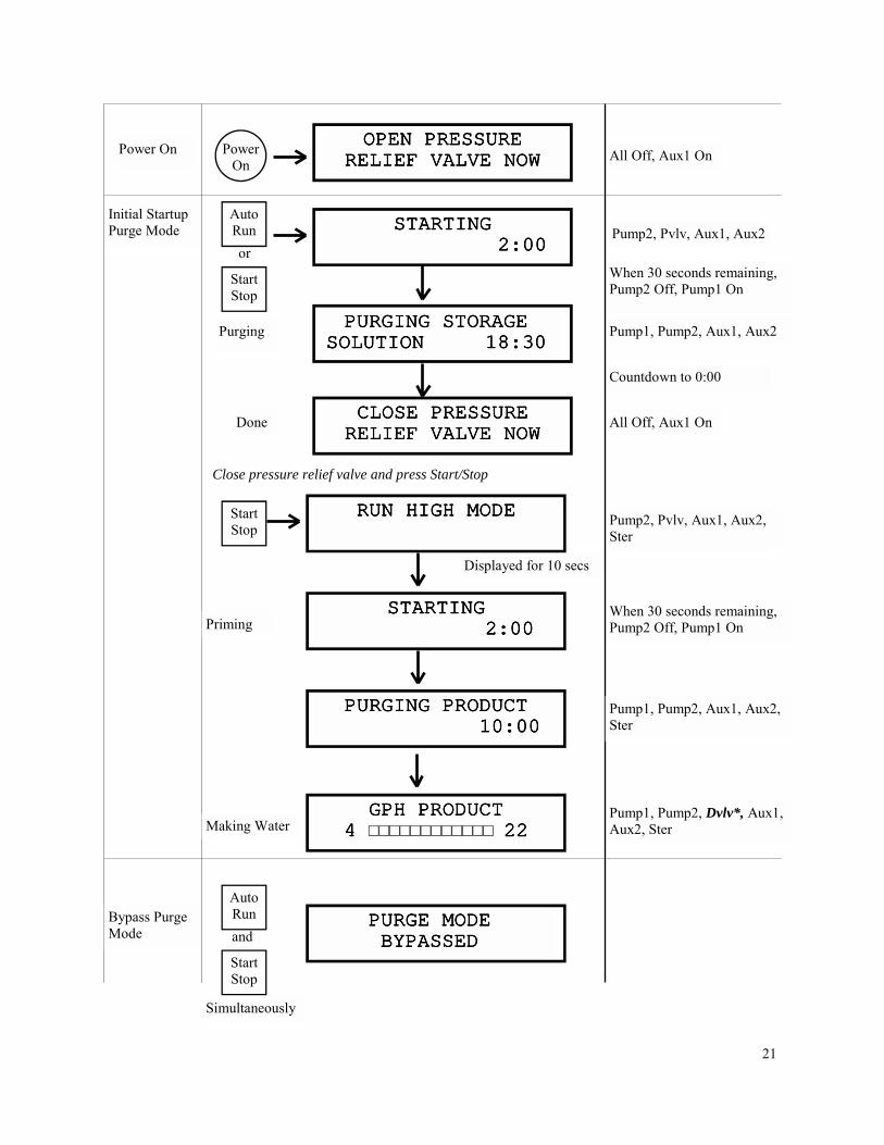
This document is a basic outline of MPC-3000 mode operations. It details what is seen on the LCD display, what outputs are active during run-time, and how the different modes work together. Gulfstream Mode is used on watermakers having two feed pumps Gulfstream & Santa Cruz). The MPC-3000 will be in Gulfstream mode if the JP2 pins on the MPC-3000 printed circuit board are jumped together. In this mode the Watermaker has two RUN modes. When the sys-tem is started it will be in RUN HIGH Mode and both feed pumps will Run and the watermaker will make 380 gallons per day. If the Stop button is held down for five seconds the watermaker will enter RUN LOW mode, Pump One, will stop and the unit will make 200 gpd.

20
21
All Off, Aux1 On
All Off, Aux1 On CLOSE PRESSURECLOSE PRESSURECLOSE PRESSURECLOSE PRESSURE RELIEF VALVE NOWRELIEF VALVE NOWRELIEF VALVE NOWRELIEF VALVE NOW
PURGING STORAGEPURGING STORAGEPURGING STORAGEPURGING STORAGE SOLUTION 18:30SOLUTION 18:30SOLUTION 18:30SOLUTION 18:30
or
STARTINGSTARTINGSTARTINGSTARTING 2:00 2:00 2:00 2:00
Initial Startup Purge Mode
Power On
OPEN PRESSUREOPEN PRESSUREOPEN PRESSUREOPEN PRESSURE RELIEF VALVE NOWRELIEF VALVE NOWRELIEF VALVE NOWRELIEF VALVE NOW
Power On
Auto Run
Start Stop
Purging
Done
Pump2, Pvlv, Aux1, Aux2
Pump1, Pump2, Aux1, Aux2
When 30 seconds remaining, Pump2 Off, Pump1 On
Countdown to 0:00
Bypass Purge Mode
Simultaneously
and
Auto Run
Start Stop
PURGE MODEPURGE MODEPURGE MODEPURGE MODE BYPASSEDBYPASSEDBYPASSEDBYPASSED
GPH PRODUCTGPH PRODUCTGPH PRODUCTGPH PRODUCT 4 4 4 4 □□□□□□□□□□□□ 22222222 Making Water
STARTINGSTARTINGSTARTINGSTARTING 2:00 2:00 2:00 2:00
RUN HIGH MODERUN HIGH MODERUN HIGH MODERUN HIGH MODE Start Stop
Displayed for 10 secs
Priming
Pump2, Pvlv, Aux1, Aux2, Ster
When 30 seconds remaining, Pump2 Off, Pump1 On
Pump1, Pump2, Dvlv*, Aux1, Aux2, Ster
Close pressure relief valve and press Start/Stop
PURGING PRODUCTPURGING PRODUCTPURGING PRODUCTPURGING PRODUCT 10:00 10:00 10:00 10:00
Pump1, Pump2, Aux1, Aux2, Ster

22
...and hold for 5 seconds
Then press again
Pump2, Pvlv, Aux1, Aux2, Ster
Press RUN HIGH MODERUN HIGH MODERUN HIGH MODERUN HIGH MODE Low Mode Start
Stop
Pump1, Dvlv*, Aux1, Aux2, Ster
When 30 seconds remaining, Pump2 Off, Pump1 On
Start Stop RUN LOW MODERUN LOW MODERUN LOW MODERUN LOW MODE
STARTINGSTARTINGSTARTINGSTARTING 1:30 1:30 1:30 1:30
GPH PRODUCTGPH PRODUCTGPH PRODUCTGPH PRODUCT 4 4 4 4 □□□□□□□□□□□□ 22222222
STARTINGSTARTINGSTARTINGSTARTING 2:00 2:00 2:00 2:00
RUN HIGH MODERUN HIGH MODERUN HIGH MODERUN HIGH MODE Manual Run Mode
Start Stop
Displayed for 10 secs
GPH PRODUCTGPH PRODUCTGPH PRODUCTGPH PRODUCT 4 4 4 4 □□□□□□□□□□□□ 22222222
Priming
Making Water
Pump2, Pvlv, Aux1, Aux2, Ster
When 30 seconds remaining, Pump2 Off, Pump1 On
Pump1, Pump2, Dvlv*, Aux1, Aux2, Ster
*NOTE: On diversion valve operation: During a water making mode, a 60 second salinity check is performed; If salinity is within tolerance (<500ppm) for a continuous 60 seconds, the diversion valve will open, and the “good” LED will be lit. If salinity is out of tolerance, the diversion valve will close, and the “reject” LED will be lit. Salinity must drop below tolerance and remain within tolerance for a continuous 60 seconds before diversion valve will open.

23
Pump1, Pump2, Dvlv*, Aux1, Aux2, Ster
Pump2 Cycles On/Off* Fvlv, Aux1
Aux1
When 30 seconds remaining, Pump2 Off, Pump1 On
Pump2, Pvlv, Aux1, Aux2, Ster
Note: pressing “Auto Run” again will add time in 1 hour increments
RUN AUTO MODERUN AUTO MODERUN AUTO MODERUN AUTO MODE 01:00 HOURS01:00 HOURS01:00 HOURS01:00 HOURS Auto
Run Auto Run Mode
STARTINGSTARTINGSTARTINGSTARTING 2:00 2:00 2:00 2:00
RUN AUTO MODERUN AUTO MODERUN AUTO MODERUN AUTO MODE 0:59 HOURS0:59 HOURS0:59 HOURS0:59 HOURS
FRESH WATERFRESH WATERFRESH WATERFRESH WATER FLUSH 5:00FLUSH 5:00FLUSH 5:00FLUSH 5:00
FLUSH TIMERFLUSH TIMERFLUSH TIMERFLUSH TIMER INTERVAL 119:59INTERVAL 119:59INTERVAL 119:59INTERVAL 119:59
Priming
Making Water
Flush
Storage
Countdown to 0
Countdown to 0
Countdown to 0 Perform Flush Cycle Repeats
Note: Pump2 flush on/off times (seconds), as well as storage time (hours), are programmable via internal software
Pump2, Fvlv, Pvlv, Aux1
Aux1
Pump2 Cycles On/Off* Fvlv, Aux1
Storage Mode
Auto Store
STARTINGSTARTINGSTARTINGSTARTING 5:30 5:30 5:30 5:30
FLUSH TIMERFLUSH TIMERFLUSH TIMERFLUSH TIMER INTERVAL 119:59INTERVAL 119:59INTERVAL 119:59INTERVAL 119:59
FRESH WATERFRESH WATERFRESH WATERFRESH WATER FLUSH 5:00FLUSH 5:00FLUSH 5:00FLUSH 5:00
Storage
Flush
Countdown to 0, repeat flush. Cycle repeats.

24
Pump2, Fvlv, Pvlv, Aux1
For 5 seconds
Press and hold
Auto Fill Mode Tank/s Full
If Tank1 (max) Switch closes..
Pump2, Pvlv, Aux1, Aux2, Ster
Pump1, Pump2, Dvlv*, Aux1, Aux2, Ster
AUTO FILL MODEAUTO FILL MODEAUTO FILL MODEAUTO FILL MODE Auto Run
STARTINGSTARTINGSTARTINGSTARTING 1:30 1:30 1:30 1:30
When 30 seconds remaining, Pump2 Off, Pump1 On
TANK/S FULLTANK/S FULLTANK/S FULLTANK/S FULL
STARTINGSTARTINGSTARTINGSTARTING 5:30 5:30 5:30 5:30
Pump2 Cycles On/Off* Fvlv, Aux1
Aux1
If timer reaches zero, another fresh water flush will be performed If tank 2 (min) switch opens, the timer will interrupt, and the unit will go back into auto-fill mode (production mode)
Auto Fill Mode
AUTO FILL MODEAUTO FILL MODEAUTO FILL MODEAUTO FILL MODE
Will produce water until tank 1 switch closes
FRESH WATERFRESH WATERFRESH WATERFRESH WATER FLUSH 5:00FLUSH 5:00FLUSH 5:00FLUSH 5:00
TANK/S FULLTANK/S FULLTANK/S FULLTANK/S FULL
Display will toggle “Tank/s Full” to “Fresh Water Flush” every 5 seconds
Countdown to 0
TANK/S FULLTANK/S FULLTANK/S FULLTANK/S FULL FLUSH TIMERFLUSH TIMERFLUSH TIMERFLUSH TIMER INTERVAL 119:59INTERVAL 119:59INTERVAL 119:59INTERVAL 119:59
Display will toggle “Tank/s Full” to “Flush Timer Interval” every 5 seconds
Countdown to 0

25
Metric
Metric
Converts to Metric Push and hold Pressing “Alarm/Disp” at any time during run cycle will cycle through the following readouts:
Run-time Readouts
Alarm Disp
GPH PRODUCTGPH PRODUCTGPH PRODUCTGPH PRODUCT 4 4 4 4 □□□□□□□□□□□□ 22222222
Alarm Disp
LPH PRODUCTLPH PRODUCTLPH PRODUCTLPH PRODUCT 15 15 15 15 □□□□□□□□□□□□ 68686868
SALINITYSALINITYSALINITYSALINITY LOW LOW LOW LOW □□□□□□□□□□ HIGHHIGHHIGHHIGH
FEED WATER PSIFEED WATER PSIFEED WATER PSIFEED WATER PSI 50 50 50 50 □□□□□□□□□□□□ 150150150150
FEED WATER BARFEED WATER BARFEED WATER BARFEED WATER BAR 3 3 3 3 □□□□□□□□□□□□ 9999
PREFILTERPREFILTERPREFILTERPREFILTER GOOD GOOD GOOD GOOD □□□□□□ REPLACEREPLACEREPLACEREPLACE
HOURS TOTALHOURS TOTALHOURS TOTALHOURS TOTAL 000000 000000 000000 000000
26
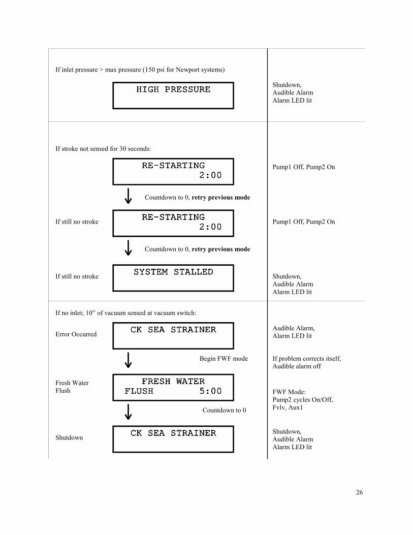
If stroke not sensed for 30 seconds:
Shutdown, Audible Alarm Alarm LED lit
HIGH PRESSUREHIGH PRESSUREHIGH PRESSUREHIGH PRESSURE
If inlet pressure > max pressure (150 psi for Newport systems)
Countdown to 0, retry previous mode
Pump1 Off, Pump2 On RERERERE----STARTINGSTARTINGSTARTINGSTARTING 2:00 2:00 2:00 2:00
Countdown to 0, retry previous mode
RERERERE----STARTINGSTARTINGSTARTINGSTARTING 2:00 2:00 2:00 2:00
Pump1 Off, Pump2 On
Shutdown, Audible Alarm Alarm LED lit
SYSTEM STALLEDSYSTEM STALLEDSYSTEM STALLEDSYSTEM STALLED
If still no stroke
If still no stroke
If no inlet; 10” of vacuum sensed at vacuum switch:
CK SEA STRAINERCK SEA STRAINERCK SEA STRAINERCK SEA STRAINER
Begin FWF mode
Audible Alarm, Alarm LED lit
If problem corrects itself, Audible alarm off
FWF Mode: Pump2 cycles On/Off, Fvlv, Aux1
FRESH WATERFRESH WATERFRESH WATERFRESH WATER FLUSH 5:00FLUSH 5:00FLUSH 5:00FLUSH 5:00
CK SEA STRAINERCK SEA STRAINERCK SEA STRAINERCK SEA STRAINER
Countdown to 0
Error Occurred
Fresh Water Flush
Shutdown Shutdown, Audible Alarm Alarm LED lit

27
If DC input voltage too high:
Begin FWF Mode To Shutdown VOLTAGE TOO LOWVOLTAGE TOO LOWVOLTAGE TOO LOWVOLTAGE TOO LOW
If DC Input voltage too low:
VOLTAGE TOO HIGHVOLTAGE TOO HIGHVOLTAGE TOO HIGHVOLTAGE TOO HIGH
Shutdown
Shutdown CHECK FUSE XCHECK FUSE XCHECK FUSE XCHECK FUSE X
If salinity probe bad or disconnected:
If blown fuse
(Where ‘x’ represents number of blown fuse (1-5))
No display, software registers that Tank1 or Tank2 is full.
If Tank1 or Tank2 switch closed for 2 minutes:
Begin FWF Mode To Shutdown
SALINITY PROBESALINITY PROBESALINITY PROBESALINITY PROBE FAILEDFAILEDFAILEDFAILED
If Tank1 AND Tank2 switch closed for 2 minutes:
TANK/S FULLTANK/S FULLTANK/S FULLTANK/S FULL
Depending on operating mode, system may at this point begin a fresh water flush, begin storage mode, or shut down. Refer to “Operating Modes”.
28
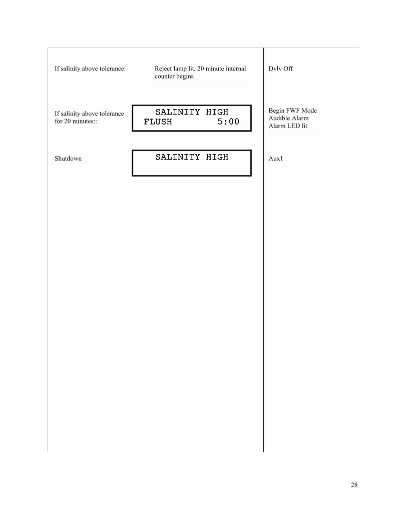
Shutdown
Begin FWF Mode Audible Alarm Alarm LED lit
SALINITY HIGHSALINITY HIGHSALINITY HIGHSALINITY HIGH FLUSH 5:00FLUSH 5:00FLUSH 5:00FLUSH 5:00
If salinity above tolerance:
SALINITY HIGHSALINITY HIGHSALINITY HIGHSALINITY HIGH Aux1
Dvlv Off Reject lamp lit, 20 minute internal counter begins
If salinity above tolerance for 20 minutes::

29
Spectra MPC-3000 Operation Guide
Monterey Mode
This document is a basic outline of MPC-3000 mode operations. It details what is seen on the LCD display, what outputs are active during run time, and how the different modes work
together.
“Monterey” mode is used on all watermakers having only one feed pump (Monterey, Newport, Catalina, & Ventura). If the JP2 pins on the MPC-3000 are not jumped together, the system will
be in “Monterey” mode. In this mode there is no “Run High” or “Run Low” mode option. Instead, the pump 2 contacts are used to control the feed pump flush speed or flush (on-off)
timing.
Care should be taken to insure that the proper mode has been selected.

30
STARTINGSTARTINGSTARTINGSTARTING 0:10 0:10 0:10 0:10
RUN MODERUN MODERUN MODERUN MODE Manual Run Mode
Bypass Purge Mode PURGE MODEPURGE MODEPURGE MODEPURGE MODE
BYPASSEDBYPASSEDBYPASSEDBYPASSED
Simultaneously
All Off, Aux1 On
All Off, Aux1 On CLOSE PRESSURECLOSE PRESSURECLOSE PRESSURECLOSE PRESSURE RELIEF VALVE NOWRELIEF VALVE NOWRELIEF VALVE NOWRELIEF VALVE NOW
PURGING STORAGEPURGING STORAGEPURGING STORAGEPURGING STORAGE SOLUTION 18:30SOLUTION 18:30SOLUTION 18:30SOLUTION 18:30
or
STARTINGSTARTINGSTARTINGSTARTING 0:30 0:30 0:30 0:30
Initial Startup Purge Mode
Power On
OPEN PRESSUREOPEN PRESSUREOPEN PRESSUREOPEN PRESSURE RELIEF VALVE NOWRELIEF VALVE NOWRELIEF VALVE NOWRELIEF VALVE NOW
Power On
Auto Run
Start Stop
Purging
Done
Pump2, Pvlv, Aux1, Aux2
Pump1, Aux1, Aux2
Countdown to 0:00
and
Auto Run
Start Stop
Start Stop
Displayed for 10 secs
GPH PRODUCTGPH PRODUCTGPH PRODUCTGPH PRODUCT 4 4 4 4 □□□□□□□□□□□□ 22222222
Priming
Making Water
Pump2, Fvlv, Aux1, Aux2, Ster
When 30 seconds remaining, Pump2 Off, Pump1 On
Pump1, Dvlv*, Aux1, Aux2, Ster
*Note on diversion valve operation: During a water making mode, a 60 second salinity check is performed. If salinity is within tolerance (<500ppm) for a continuous 60 seconds, the diversion valve will open, and the “good” LED will be lit. If salinity is out of tolerance, the diversion valve will close, and the “reject” LED will be lit. Salinity must drop below tolerance and remain within tolerance for a continuous 60 seconds before diversion valve will open.
* Monerey Mode B Only– Jumper at JP2 Removed *
31
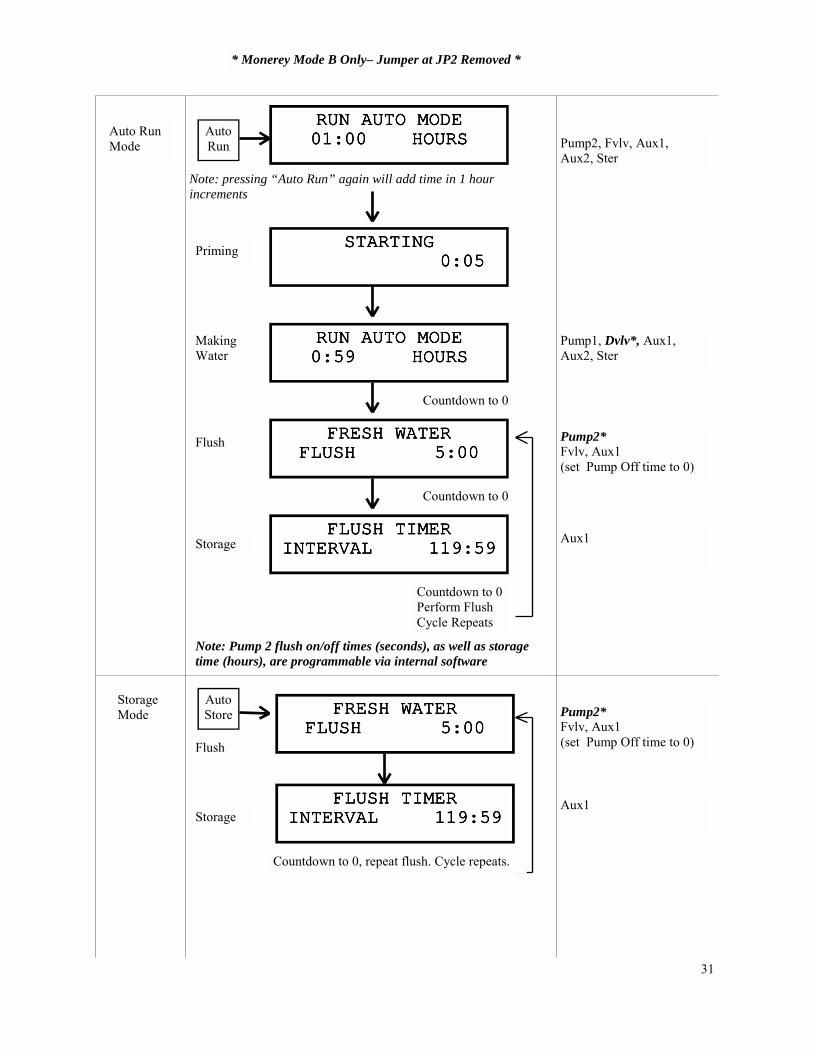
Aux1
Pump1, Dvlv*, Aux1, Aux2, Ster
Pump2* Fvlv, Aux1 (set Pump Off time to 0)
Aux1
Pump2, Fvlv, Aux1, Aux2, Ster
Note: pressing “Auto Run” again will add time in 1 hour increments
RUN AUTO MODERUN AUTO MODERUN AUTO MODERUN AUTO MODE 01:00 HOURS01:00 HOURS01:00 HOURS01:00 HOURS Auto
Run Auto Run Mode
STARTINGSTARTINGSTARTINGSTARTING 0:05 0:05 0:05 0:05
RUN AUTO MODERUN AUTO MODERUN AUTO MODERUN AUTO MODE 0:59 HOURS0:59 HOURS0:59 HOURS0:59 HOURS
FRESH WATERFRESH WATERFRESH WATERFRESH WATER FLUSH 5:00FLUSH 5:00FLUSH 5:00FLUSH 5:00
FLUSH TIMERFLUSH TIMERFLUSH TIMERFLUSH TIMER INTERVAL 119:59INTERVAL 119:59INTERVAL 119:59INTERVAL 119:59
Priming
Making Water
Flush
Storage
Countdown to 0
Countdown to 0
Countdown to 0 Perform Flush Cycle Repeats
Note: Pump 2 flush on/off times (seconds), as well as storage time (hours), are programmable via internal software
Storage Mode
Auto Store
FLUSH TIMERFLUSH TIMERFLUSH TIMERFLUSH TIMER INTERVAL 119:59INTERVAL 119:59INTERVAL 119:59INTERVAL 119:59
FRESH WATERFRESH WATERFRESH WATERFRESH WATER FLUSH 5:00FLUSH 5:00FLUSH 5:00FLUSH 5:00
Storage
Flush
Countdown to 0, repeat flush. Cycle repeats.
Pump2* Fvlv, Aux1 (set Pump Off time to 0)
* Monerey Mode B Only– Jumper at JP2 Removed *
32
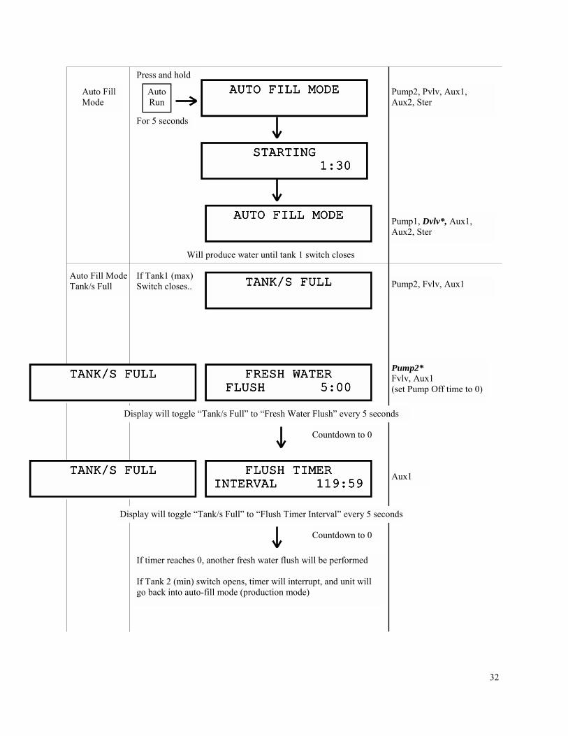
Pump2, Fvlv, Aux1
For 5 seconds
Press and hold
Auto Fill Mode Tank/s Full
If Tank1 (max) Switch closes..
Pump2, Pvlv, Aux1, Aux2, Ster
Pump1, Dvlv*, Aux1, Aux2, Ster
AUTO FILL MODEAUTO FILL MODEAUTO FILL MODEAUTO FILL MODE Auto Run
STARTINGSTARTINGSTARTINGSTARTING 1:30 1:30 1:30 1:30
TANK/S FULLTANK/S FULLTANK/S FULLTANK/S FULL
Pump2* Fvlv, Aux1 (set Pump Off time to 0)
Aux1
If timer reaches 0, another fresh water flush will be performed If Tank 2 (min) switch opens, timer will interrupt, and unit will go back into auto-fill mode (production mode)
Auto Fill Mode
AUTO FILL MODEAUTO FILL MODEAUTO FILL MODEAUTO FILL MODE
Will produce water until tank 1 switch closes
FRESH WATERFRESH WATERFRESH WATERFRESH WATER FLUSH 5:00FLUSH 5:00FLUSH 5:00FLUSH 5:00
TANK/S FULLTANK/S FULLTANK/S FULLTANK/S FULL
Display will toggle “Tank/s Full” to “Fresh Water Flush” every 5 seconds
Countdown to 0
TANK/S FULLTANK/S FULLTANK/S FULLTANK/S FULL FLUSH TIMERFLUSH TIMERFLUSH TIMERFLUSH TIMER INTERVAL 119:59INTERVAL 119:59INTERVAL 119:59INTERVAL 119:59
Display will toggle “Tank/s Full” to “Flush Timer Interval” every 5 seconds
Countdown to 0

33