MP114-1 The Key is in the Content- Electrical Families Key is in the Content: Electrical Families...
12
The Key is in the C Joel Londenberg Jarrod Baumann MP114-1 Highly customized c Autodesk® Revit® MEP model. Ele documented in both 3D and with 2D and power families to drive your sc demonstrate this live in Revit MEP MEP. Familiarity with the Family Ed About the Speaker: Joel is an independent training and years experience with leading mec wide range of projects. These proje custom homes and multi-family hou worked for manufacturers performi also a key part of the team tasked well as assisting major HVAC man [email protected] Jarrod is currently the BIM Manage West Engineering, Inc., where he c staff of the mechanical, plumbing, a AutoCAD® since release 10, and w experience utilizing AutoCAD and R educational, medical, and residenti training for Revit as well as assistin distribution. [email protected] Content: Electrical Families content is key to producing great construction docum ectrical engineers have a large number of devices th D symbols. You can leverage embedded information chedule data. Learn how to bend Revit MEP to fit you P 2010. This class will benefit anyone actively implem ditor is required. Q & A is encouraged d implementation consultant specializing in Revit® M chanical and plumbing design and supporting electric ects are in fields such as retail, commercial, educatio using, and range in size from 3,000 to 300,000 squa ing equipment design using various 3D software pac with implementing Revit MEP for Design West Engin nufacturers with developing their Revit content for dis er for Tilden-Coil Constructors, Inc. and previously w created standards for and supported the engineering and electrical design departments. He has been an a with his start in the MEP field in 1995, he has had mu Revit® software on a wide variety of MEP projects in ial fields. Jarrod has much experience with impleme ng major HVAC manufacturers with developing their s ments from your hat need to be n in your lighting ur needs. We will menting Revit MEP. He has many cal design for a onal, medical, are feet. Joel has ckages, and was neering, Inc. as stribution. worked for Design g and production active user of uch practical n the commercial, entation and Revit content for
Transcript of MP114-1 The Key is in the Content- Electrical Families Key is in the Content: Electrical Families...
The Key is in the Content: Electrical FamiliesJoel Londenberg Jarrod Baumann
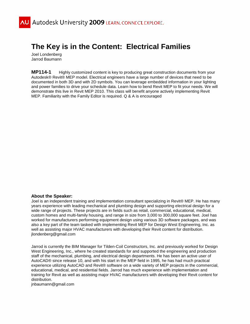
MP114-1 Highly customized content is key to producing great construction documents from your Autodesk® Revit® MEP model. Electrical engineers have a large number of devices that need to be documented in both 3D and with 2D symbols. You can leverage embedded information in your lighting and power families to drive your schedule data. Learn how to bend Revit demonstrate this live in Revit MEP 2010. This class will benefit anyone actively implementing Revit MEP. Familiarity with the Family Editor is required. Q & A is encouraged
About the Speaker: Joel is an independent training and implementation consultant specializing in Revityears experience with leading mechanical and plumbing design and supportwide range of projects. These projects are in fields such as retail, commerccustom homes and multi-family housing, and range in size from 3,000 to 300,000 square feet. Joel has worked for manufacturers performing equipment design using various 3D software packages, also a key part of the team tasked with implementing Revit MEP for Design West Engineeringwell as assisting major HVAC manufacturers with developing their Revit content for [email protected]
Jarrod is currently the BIM Manager for West Engineering, Inc., where he createstaff of the mechanical, plumbing, and electrical design departments. He has been an active user of AutoCAD® since release 10, and with his start in the MEP field in 1995, he has had much practical experience utilizing AutoCAD and Revit® software on a wide variety of MEP projects in the commercial, educational, medical, and residential fields. Jarrod training for Revit as well as assisting major HVAC manufacturers with developing their Revit content for distribution. [email protected]
The Key is in the Content: Electrical Families
Highly customized content is key to producing great construction documents from your Revit® MEP model. Electrical engineers have a large number of devices that need to be
documented in both 3D and with 2D symbols. You can leverage embedded information in your lighting and power families to drive your schedule data. Learn how to bend Revit MEP to fit your needs. We will demonstrate this live in Revit MEP 2010. This class will benefit anyone actively implementing Revit MEP. Familiarity with the Family Editor is required. Q & A is encouraged
training and implementation consultant specializing in Revit® MEPmechanical and plumbing design and supporting electrical design
wide range of projects. These projects are in fields such as retail, commercial, educational, medical, family housing, and range in size from 3,000 to 300,000 square feet. Joel has
worked for manufacturers performing equipment design using various 3D software packages, ked with implementing Revit MEP for Design West Engineering
well as assisting major HVAC manufacturers with developing their Revit content for distribution.
Jarrod is currently the BIM Manager for Tilden-Coil Constructors, Inc. and previously worked for Design , where he created standards for and supported the engineering and production
staff of the mechanical, plumbing, and electrical design departments. He has been an active user of se 10, and with his start in the MEP field in 1995, he has had much practical
experience utilizing AutoCAD and Revit® software on a wide variety of MEP projects in the commercial, educational, medical, and residential fields. Jarrod has much experience with implement
Revit as well as assisting major HVAC manufacturers with developing their Revit content for
The Key is in the Content: Electrical Families
Highly customized content is key to producing great construction documents from your Revit® MEP model. Electrical engineers have a large number of devices that need to be
documented in both 3D and with 2D symbols. You can leverage embedded information in your lighting MEP to fit your needs. We will
demonstrate this live in Revit MEP 2010. This class will benefit anyone actively implementing Revit
MEP. He has many electrical design for a
ial, educational, medical, family housing, and range in size from 3,000 to 300,000 square feet. Joel has
worked for manufacturers performing equipment design using various 3D software packages, and was ked with implementing Revit MEP for Design West Engineering, Inc. as
well as assisting major HVAC manufacturers with developing their Revit content for distribution.
c. and previously worked for Design the engineering and production
staff of the mechanical, plumbing, and electrical design departments. He has been an active user of se 10, and with his start in the MEP field in 1995, he has had much practical
experience utilizing AutoCAD and Revit® software on a wide variety of MEP projects in the commercial, h implementation and
Revit as well as assisting major HVAC manufacturers with developing their Revit content for

The Key is in the Content: Electrical Families
2
The Key is in the Content
Why would we make this statement?
Each piece of content that you place in your model has to fulfill a number of needs. In your “Building Information Model” you need a 3 dimensional representation of the part. This is used for the soft requirements like visualization and rendering, and the hard requirements like collision detection and prevention. You also need a good 2 dimensional representation. This will provide for good, readable construction documents. Finally you need meta data – parameters that help you indentify and schedule you detailed selections.
This means that as much as we would like to just dive in a project, to be most productive, first we need to focus on the components.
3D Geometry
The first important consideration is which family template to use. The templates available with the default installation of Revit® MEP are many and varied. They are also largely irrelevant. For instance, the available lighting fixture templates are:
• Lighting Fixture ceiling based.rft • Lighting Fixture wall based.rft • Lighting Fixture.rft
Any custom family created with the ceiling or wall based templates will be un-usable for most Revit® MEP users. Because we work with a linked architectural model, the walls and ceilings only function as a “Face” through the linked file.
However, there is no “Face based/hosted” lighting fixture template. This means we will have to use the “Generic Model face based.rft” template in order to make use of the walls and ceilings in our linked architectural models.
There is no difference between the generic face based template and a specific use template, so long as you change the family category and related settings.
For the most useable families, you will need to the geometry to be flexible. There are a few general rules to follow:
Revit family rule #1: Reference planes out the wazoo! a. You should use reference planes within your family to “box out” your geometry b. Add dimensions to the reference planes, then add parameters to flex those
dimensions and always test to be sure that they move as expected c. Only after the reference planes are successfully flexible, add geometry locked to
those reference planes Revit family rule #2: Draw in space, then constrain

The Key is in the Content: Electrical Families
3
a. Draw your lines slightly away from the planes, then use the Align -> Lock command to force the sketched lines to attach and stay attached to your reference planes.
b. Drag geometry grips to a reference plane and select the Lock icon
Step by step…
Let’s start with a typical 2’ x 4’ recessed florescent light fixture
Create a new family using the ‘Generic Model face based.rft’ template. Save it with your company standard naming criteria, such as “AU-Lite-Rect.rfa”.
Go to Manage -> Category and Parameters and change the family category to Lighting Fixture. This is the same dialog box where you can turn on the Light Source for rendering, but leave it turned off until you have completed the rest of you modeling tasks. It’s easier if you leave your view as clear as possible while working.
Now open the Ref. Level view. Click Create -> Reference Plane . We want to use the two existing reference planes as the lower left corner of our family, so lay out reference planes to define the top and right hand edges. Dimension these from the two existing planes and label the dimensions with new Type Parameters named “Length” and “Width”.
Next open the Left elevation view. Notice in the figure below, that the grey block indicating the “Face” in our face based template is below the Ref. Level. It’s important to remember that when building the geometry. This means that for our example of a light fixture that is recessed up in to the ceiling, we will have to build it to hang down below Ref. Level in this left view.

The Key is in the Content: Electrical Families
4
Draw a reference plane below Ref. Level to represent the top surface of the fixture. Dimension and label this plane also.
Draw a final plane above Ref. Level to represent the face frame of the fixture. Dimension this plane at .25” above Ref. Level and lock that dimension.
Side note: When installing a recessed light fixture in a gypsum board ceiling, the face frame of the fixture will hang below the surface of the ceiling. When your ceiling is a suspended grid, the light sits above the surface of the ceiling on top of the T-bar grid. In both of these cases, your Revit family should hang below the ceiling. This is because our families cannot cut their hosting surface when working in a linked architectural model environment and would therefore, not show up in a camera view of the room unless they are below the ceiling surface.
Once all the planes are in place, you are ready to generate your geometry. While still in the Left view click Create -> Solid -> Extrusion , draw the profile, taking care to lock the lines to the reference planes, finish your extrusion. Toggle back to the Ref. Level view, select the extrusion to highlight it’s grips and drag and lock them to the reference planes.
Now to dress it up just a little, in the Left view click Create -> Set and select the reference plane defining the face of the fixture below the ceiling to make this your new workplane. Go back to the Ref. Level view. Click Create -> Void -> Extrusion , set your depth to 1/8”, offset to 1/2", click the rectangle tool, click on one corner of the fixture, hover over the opposite corner, click the space bar to orient the offset as needed and click that opposite corner. Now dimension and lock the four lines to the four reference planes and finish.
Materials
We can quickly improve the look of our fixture by adding a couple materials. Manage -> Materials shows the list of material definitions already in your family. Click the Duplicate button, name your material “White Paint”, check Use Render Appearance for Shading , go to the Render Appearance tab, click Replace , and assign the white paint material.

Now the light fixture looks nice in a shaded view, lets add one more material to improve rendered appearance. In the Materials dialog box, create a new material called “Light Lens”. For this select the “Glass Light Bulb On” materialto Transparency and drag the slider all the way to the left and click OKto shaded with edges, then Modify
Light Source
Adding a light source to your model is easily done in the Family Category and Parameters dialog box. Once the light source is enabledand Edit the Light Source Definition. Select the Rectangular Emit frHemispherical Light Distribution. Go to your Left view and rotate the light source to point the correct direction. Use the align tool to lock your light source to of the fixture 1/4" below the ceiling. Next gyour remaining reference planes.
In the Types dialog box, scroll down to the Photometrics section, you should see two
Construction Documents
Our new light fixture works well, sticking to a ceiling as the hosting face. The geometry is accurate, and it looks good in a section, camera view and rendering. Now we need to be sure it handles our 2D construction documents equally well.
Some light fixtures are typically shown on plans with scaleable symbols, usually items that would be too small to show at typical plan view scales. Wall sconces, down lights, and pendants are some examples of this. Most firms show 2’ x 4’ lights full size.
The Key is in the Content : Electrical Famil
the light fixture looks nice in a shaded view, lets add one more material to improve rendered appearance. In the Materials dialog box, create a new material called “Light Lens”.
“Glass Light Bulb On” material, then scroll down the Render Appearance tab and drag the slider all the way to the left and click OK. Go to a 3D view, set it
Modify -> Paint and select the recessed surface of the void
Adding a light source to your model is easily done in the Family Category and Parameters Once the light source is enabled select it in your view and go to Element Properties
and Edit the Light Source Definition. Select the Rectangular Emit from Shape and Hemispherical Light Distribution. Go to your Left view and rotate the light source to point the
Use the align tool to lock your light source to the reference plane at the face below the ceiling. Next go back to the plan view and lock the light source to
reference planes.
dialog box, scroll down to the Photometrics section, you should see two Parameters for setting the light source width and length. Use the formula field to make these parameters equal to the Width and Length that drive the dimensions we placed earlier.
For families with multiple light sources, such as a chandelier, you will need to create a nested familylight source for each of the lamps and turn off the light source in the parent family.
Our new light fixture works well, sticking to a ceiling as the hosting face. The geometry is accurate, and it looks good in a section, camera view and rendering. Now we need to be sure it handles our 2D construction documents equally well.
Some light fixtures are typically shown on plans with scaleable symbols, usually items that would be too small to show at typical plan view scales. Wall sconces, down lights, and
mples of this. Most firms show 2’ x 4’ lights full size.
: Electrical Famil ies
5
the light fixture looks nice in a shaded view, lets add one more material to improve its rendered appearance. In the Materials dialog box, create a new material called “Light Lens”.
e Render Appearance tab . Go to a 3D view, set it
and select the recessed surface of the void.
Adding a light source to your model is easily done in the Family Category and Parameters select it in your view and go to Element Properties
om Shape and Hemispherical Light Distribution. Go to your Left view and rotate the light source to point the
the reference plane at the face o back to the plan view and lock the light source to
dialog box, scroll down to the Photometrics section, you should see two Parameters for setting the light source width and length. Use the formula field
make these parameters equal to the Width and Length that drive the dimensions we placed earlier.
For families with multiple light a chandelier, you will
need to create a nested family to be the light source for each of the lamps and
ff the light source in the parent
Our new light fixture works well, sticking to a ceiling as the hosting face. The geometry is accurate, and it looks good in a section, camera view and rendering. Now we need to be sure
Some light fixtures are typically shown on plans with scaleable symbols, usually items that would be too small to show at typical plan view scales. Wall sconces, down lights, and

The Key is in the Content: Electrical Families
6
It’s possible to just use the 3D geometry, but this gives us less control. You are better served by selecting the 3D extrusion and turning it off in plan view. Select the extrusion Modify Extrusion -> Visibility Settings and uncheck Plan/RCP. Now when we place the light family in our project and place it on a face parallel to a plan view, the geometry will not be visible in either Plan or RCP views.
Since the 3D geometry is gone, we will need to replace it with something that suits our firm’s drafting standards. Start a new family with the “Detail .rft” template. Just as we started the previous family, add the top and right side Reference Planes and dimension them as before. This time, label the dimensions “2D_Length” and “2D_Width” to easily differentiate the symbol dimensions from the 3D geometry dimensions. Also, make sure that these are set to be “Instance Parameters”.
Before we draw the lines that will make up our symbol, we need to set up a few items to represent our desired line weights. In the detail component family go to Manage -> Settings -> Object Styles . Under Modify Subcategories, click the New button. Here you can add as many line styles as needed to recreate your drafting standards.
If you are careful to keep your naming consistent, all the “Thin” items from various families in your project will be the same thickness.
dmaurer
Text Box
ITEM

The Key is in the Content: Electrical Families
7
Now you can draw your lines and assign them the appropriate line weights by category. Don’t forget the Revit modeling rules: #1 Ref planes out the wazoo #2 Draw in space then constrain. We will modify rule #2 for this case. Since there are so few items for Revit to associate together, you can just draw directly on top of the reference planes and the automatic associations will work well.
Many firms also indicate the emergency battery equipped fixtures with a solid fill. We can also add this to the detail component. Pick Create -> Filled Region and change your active Line Style to “<Invisible lines>” since you have already drawn the boundary with firm specific lines. Draw outline of the filled region, choose your fill type from the Region Properties and click Ok. To control the visibility of this filled region in your project, select it and go to element properties. Pick the tiny button at the right hand end of the Visiblity row and link it to a new instance parameter called “2D_Emer”.
Now load this detail component family in to the light fixture family and place off to the side. Since our detail component and light fixture are both flexible, we need to link the detail component dimensions to inside the light fixture family. Select the detail component and go to element properties. You should see the parameters “2D_Width”, “2D_Length” and “2D_Emer”.
Again, click the tiny button on the right hand side of the emergency fill parameter and create a new parameter in the light fixture family to link it too. This should be a type parameter since
you will likely want to keep your emergency fixture setting as a type parameter. Link your 2D_Width and 2D_Length parameters to the width and length parameters in your light fixture. Now flex you fixture to be sure that both the 3D geometry and 2D detail component stay in sync.
Now use the align/lock command to keep your detail component in place with your geometry.
Power Connector
You can simply place an Electrical Connector on any face of the light fixture family. When you are using the family in a project, it’s easiest to wire your fixtures if you place the connector in the center of the family as seen in the project. Once the connector is placed, go to its element properties and change the System Type to “Power – Balanced” and the Load Classification to “Lighting”. The Apparent Load can be linked to the built in parameter

The Key is in the Content: Electrical Families
8
Apparent Load. Voltage should be linked to a shared parameter of your creation. Number of Poles should be linked to a family parameter.
Family Types
Now your family is ready for placement within a project. It will show up well everywhere except one. Our last main task is adding the data that we want to show up in our schedules.
This is one example of a Luminaire Schedule. Some of these columns of data can be driven by the built in parameters we find in every Light Fixture. We have the following parameters to match up with our schedule columns:
• Type Mark = TYPE (only visible in your project) • Voltage = VOLTS (we created this shared parameter to drive our electrical
connector) • Description = FIXTURE DESCRIPTION • Manufacturer = MANUF. • Model = CATALOG # • Type Comments = NOTES
This leaves WATTAGE, LAMPS, MOUNTING and SYMBOL yet to be accounted for. You will need to create new shared parameters for these. All of them should be defined as ‘Common’ ‘Text’. SYMBOL needs special handling, but the rest are simple descriptive text.
We will also need to add an additional shared parameter to be used to sort out what families show up in each schedule. Let’s call it “SchedType” and in the family formula it to always equal “Luminaire”. The reason we need this parameter is that not all lights in our projects are able to be set with the family category “Lighting Fixture”. This will be demonstrated in the next section.
When you create the schedule to be used in your project documents, add this “SchedType” parameter and filter out any families that are not equal to “Luminaire”.
Unfortunately, Revit cannot integrate a view of the family with the schedule. The SYMBOL parameter only provides us with space in which we can manually coordinate the picture shown. In order to force a minimum of 4 text lines in height we have to put special characters in the SYMBOL text parameter. To do this, open a text editor and type the following:
Quote – Enter – Tab – Enter – Tab – Enter - Quote

The Key is in the Content: Electrical Families
9
Then select all the lines of text and copy them (Ctrl-C). In the family editor, paste them (Ctrl-V) in the Formula cell of the SYMBOL parameter. Now you will have a consistent available height cell in which to draw your symbol.
Scalable Symbols
We have finished one example of a light fixture that mounts to the ceiling and is shown in plan views with a full size symbol. Now we will look at an example of a fixture that is typically shown with a scaleable symbol – a wall sconce
There is additional effort needed to craft MEP families for use with a linked Architectural building model. Since the building elements are not directly in the MEP model, Wall Hosted/Ceiling Hosted families cannot be used. The only way your families can interact with the linked model is by means of faces. For wall mounted families, this becomes a bit more complicated.
The ‘Generic Model face based.rft’ family template is oriented as if it was a floor. In the Ref. Level view you are looking down at the face that you will be using as your host. This means that when you then use this face hosted family on a vertical surface the family rotates as if you are facing a wall and picking up the family from the floor and putting it’s back against the wall. See the image below.
The next issue that must be resolved is the visibility of the geometry and the plan view symbol. For fixtures like these, typical practice is to show a scalable symbol on your plan view representing a wall sconce. This means that we must hide the geometry in the family in the appropriate view orientation. Because we are rotating the entire family to a vertical wall surface, the Plan/RCP view
The Key is in the Content: Electrical Families
10
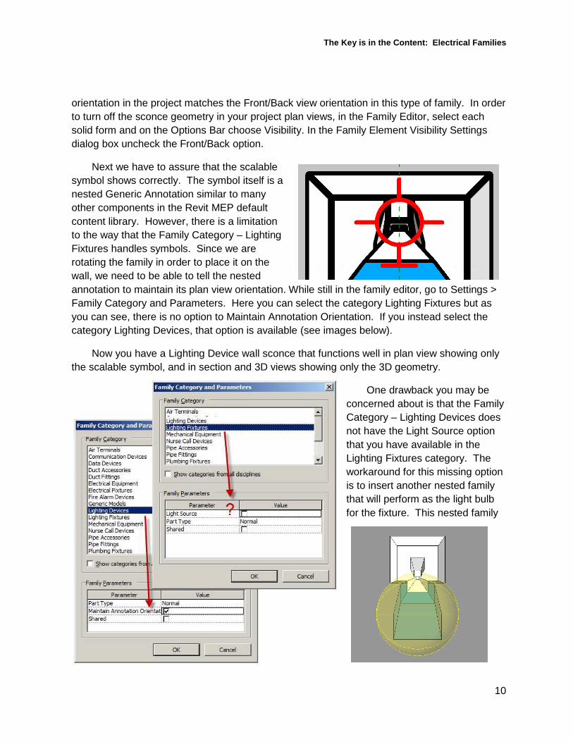
orientation in the project matches the Front/Back view orientation in this type of family. In order to turn off the sconce geometry in your project plan views, in the Family Editor, select each solid form and on the Options Bar choose Visibility. In the Family Element Visibility Settings dialog box uncheck the Front/Back option.
Next we have to assure that the scalable symbol shows correctly. The symbol itself is a nested Generic Annotation similar to many other components in the Revit MEP default content library. However, there is a limitation to the way that the Family Category – Lighting Fixtures handles symbols. Since we are rotating the family in order to place it on the wall, we need to be able to tell the nested annotation to maintain its plan view orientation. While still in the family editor, go to Settings > Family Category and Parameters. Here you can select the category Lighting Fixtures but as you can see, there is no option to Maintain Annotation Orientation. If you instead select the category Lighting Devices, that option is available (see images below).
Now you have a Lighting Device wall sconce that functions well in plan view showing only the scalable symbol, and in section and 3D views showing only the 3D geometry.
One drawback you may be concerned about is that the Family Category – Lighting Devices does not have the Light Source option that you have available in the Lighting Fixtures category. The workaround for this missing option is to insert another nested family that will perform as the light bulb for the fixture. This nested family
The Key is in the Content: Electrical Families
11
will be of the Family Category – Lighting Fixtures but will contain no 3D geometry. Start with an empty Generic Model, change it to the Lighting Fixtures category and select the Light Source and Shared options. Next insert this Lighting Fixture “Bulb” into your Lighting Device sconce. Now it will cast light in a rendering in either your MEP project file, or the Architect’s project file when they link the MEP model into theirs.
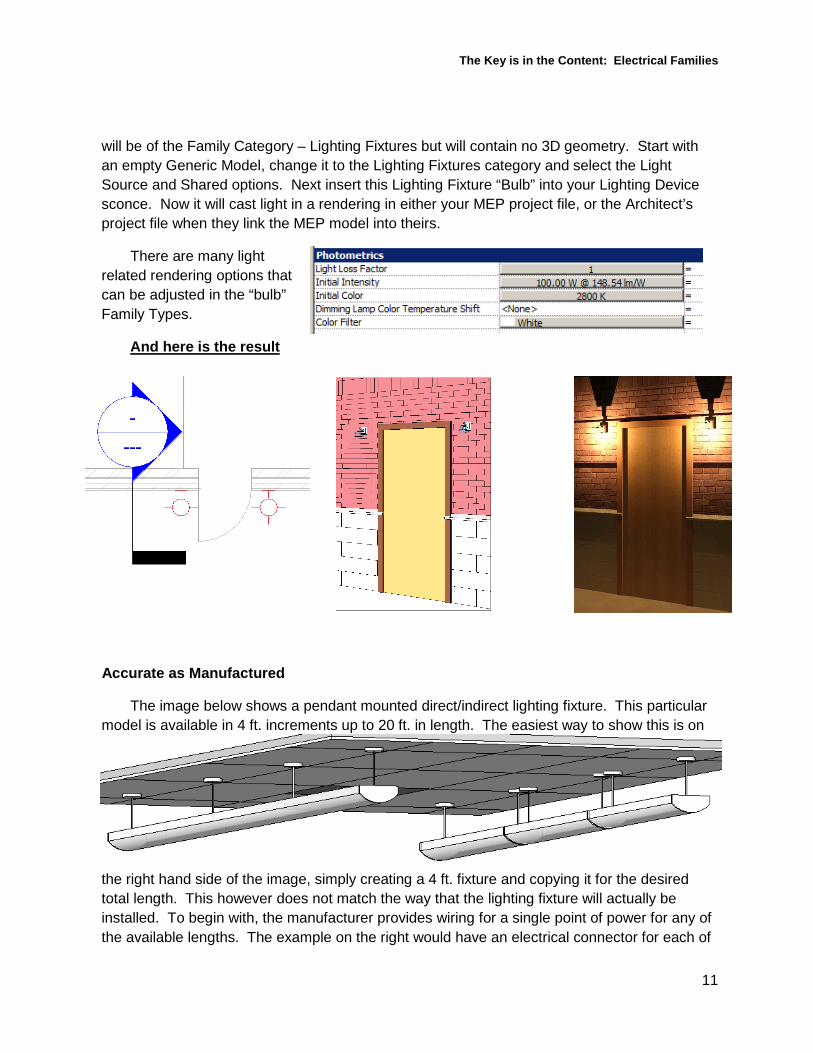
There are many light related rendering options that can be adjusted in the “bulb” Family Types.
And here is the result
Accurate as Manufactured
The image below shows a pendant mounted direct/indirect lighting fixture. This particular model is available in 4 ft. increments up to 20 ft. in length. The easiest way to show this is on
the right hand side of the image, simply creating a 4 ft. fixture and copying it for the desired total length. This however does not match the way that the lighting fixture will actually be installed. To begin with, the manufacturer provides wiring for a single point of power for any of the available lengths. The example on the right would have an electrical connector for each of

The Key is in the Content: Electrical Families
12
the 4 ft. lengths. They also join the segments together in such a way that fewer mounting points are required than is shown on the right.
We created the family on the left in order to better match the installed conditions, eliminate the need to wire up each 4 ft. section and to accurately show the mounting requirements. The difficult part of this modeling task was getting the pendant mounts to show up in the correct quantity and the correct location based on the length of the fixture. To do this we used a nested family for the pendant mount part of the fixture, inserted then constrained and arrayed it along the lighting fixtures length.
After creating the array, select one of the arrayed components and then select the dimension extension line, not the array quantity number, and you can apply a Label/Parameter to control the array quantity (see image below).
After your parameters are assigned you can then use formulas as shown to accurately control the family per the manufacturer’s published data.
Thank you . . .
We appreciate you joining us for the class. Hopefully you have found the lecture and this handout useful for your continued use of Revit MEP.
As always, we recommend that any user regularly visits the Revit MEP forums at http://forums.augi.com . There is no better source of day to day help for Revit MEP users figuring out their problems, for learning new features and ultimately for reducing their stress level as we all help each other.