
MP101MA-PDG 13.09 - Norditechnorditech.com.au/wp-content/uploads/2019/09/MP101M_User_Manu… ·...
196
TECHNICAL MANUAL SUSPENDED PARTICULATE BETA GAUGE MONITOR MP101M - APRIL 2014 - 111 bd Robespierre, 78300 POISSY - -TEL. 33(0)-1.39.22.38.00 – FAX 33(0)-1.39 65.38.08 http://www.environnement-sa.com GENERAL CHARACTERISTICS PRINCIPLE OF OPERATION OPERATION PREVENTIVE MAINTENANCE CORRECTIVE MAINTENANCE APPENDIX
Transcript of MP101MA-PDG 13.09 - Norditechnorditech.com.au/wp-content/uploads/2019/09/MP101M_User_Manu… ·...
TECHNICAL MANUAL
SUSPENDED PARTICULATE BETA GAUGE MONITOR
MP101M
- APRIL 2014 -
111 bd Robespierre, 78300 POISSY - -TEL. 33(0)-1.39.22.38.00 – FAX 33(0)-1.39 65.38.08 http://www.environnement-sa.com
GE
NE
RA
L
CH
AR
AC
TE
RIS
TIC
S
PR
INC
IPL
E O
F
OP
ER
AT
ION
O
PE
RA
TIO
N
PR
EV
EN
TIV
E
MA
INT
EN
AN
CE
C
OR
RE
CT
IVE
M
AIN
TE
NA
NC
E
AP
PE
ND
IX

Environnement S.A MP101M Duplication prohibited
SEPTEMBER 20130–2
Warranty
Defects that fall under warranty
The seller shall undertake to remedy any operational malfunction resulting from a manufactured or material defect within the limits of the provision below.
The seller shall not be liable in the case of a defect caused either by materials supplied by the buyer or by a design imposed by the buyer.
Any warranty is also invalid in the case of damage resulting from normal wear and tear, accident, disaster, misuse, fault or negligence of or by Buyer, causes external to the Products such as, but not limited to, unauthorized repairs or part replacement, electrical power surges, improper storage of the Product, use of the Product in a manner for which it was not designed.
Duration and starting point of the warranty
Unless otherwise stipulated, the warranty period shall have a duration of twelve months from the date of delivery within the meaning of article 6 paragraph 2 of the «ENVIRONNEMENT S.A: 2013 INTERNATIONAL GENERAL TERMS AND CONDITIONS OF SALES», even if the shipment or assembly is postponed for any reason outside the seller's control.
Unless agreed upon by both parties, the repair, modification or replacement of parts during the warranty period will not extend or renew the original equipment warranty period.
Buyer's obligation
In order to file a claim under warranty, the buyer must notify the seller immediately in writing of any defect in the equipment and supply evidence in proof thereof. The buyer must provide the seller with the opportunity to observe and remedy the said defects. In addition, the buyer must not carry out any repairs or have repairs made by a third party without the written agreement of the seller.
The buyer is required to check the equipment as soon as possible upon receipt and acceptance and no later than eight days following receipt. Failing to do so might invalidate any claims made later regarding a declared defect.
Any installation, maintenance, repair, service of the product performed by any person or entity other than seller without seller's prior written approval, or any use of replacement parts not supplied by seller, shall immediately void and cancel all warranties with respect to the affected product.
Exercising the warranty
Once notified of a defect, the seller shall be responsible for remedying the defect at its own expense. The seller, however, reserves the right to modify the mechanisms of the equipment as needed to comply with its obligations.
The work to satisfy the warranty obligation shall be carried out, principally, in the seller's workshop after the buyer has returned the equipment or the defective parts to the seller for the purposes of repair or replacement, whichever the seller deems best.
However, if the nature of the equipment is such that the repair has to be carried out at the location where it was installed, the seller shall only be responsible for the on-site labor costs involved in direct service of the analyzer itself. The buyer is responsible for the cost of any additional measures needed to provide unrestricted access.
The cost of transport of the equipment or the defective parts, as well as the return of the repaired or replaced equipment or part, shall be borne by the buyer. In the case of on-site repair, the buyer shall be responsible for any travelling and accommodation expenses of the seller's representative.
Defective parts replaced free of charge, under warrantee, must be returned to the seller and shall become its property once again.
Duplication prohibited MP101M Environnement S.A
0–3SEPTEMBER 2013
SUMMARY
CHAPTER 0 SAFETY GUIDELINES
0.1 WARNING 0–9
0.2 REMINDER OF PRINCIPAL STATUTORY TECHNICAL PRECAUTIONS 0–10
0.3 PRESENTATION OF EQUIPMENT 0–11
0.4 RISKS ASSESSMENTS 0–13
0.5 RISK ANALYSES 0–14
0.6 RADIATION PROTECTION RECOMMENDATIONS 0–15
0.7 SAFETY INSTRUCTIONS - EXAMPLE 0–16
0.8 TECHNICAL CONTROLS OF RADIOPROTECTION 0–17
0.9 END OF LIFE OF THE ANALYZER 0–17
CHAPTER 1 GENERAL – CHARACTERISTICS
1.1. GENERAL 1–3
1.2. CHARACTERISCS 1–13
CHAPTER 2 PRINCIPLE OF OPERATION
2.1. BETA GAUGE PRINCIPLE (FIGURE 2–1 AND FIGURE 2–2) 2–3
2.2. FLOW REGULATION PRINCIPLE 2–6
2.3. ACQUISITION AND PROCESSING OF MEASUREMENT PARAMETERS 2–8
2.4. ORGANIZATION OF MEASUREMENTS 2–8
2.5. REGULATED SAMPLING TUBE (RST) 2–11
CHAPTER 3 OPERATION
3.1 INITIAL START-UP 3–4
3.2 PROGRAMMING THE MP101M 3–7
3.3 DESCRIPTION OF THE DIFFERENT SCREENS 3–10
CHAPTER 4 PREVENTIVE MAINTENANCE
4.1. SAFETY INSTRUCTIONS 4–2
4.2. MAINTENANCE CALENDAR 4–3
4.3. MAINTENANCE OPERATION SHEETS 4–3
4.4. EQUIPMENT NECESSARY FOR MAINTENANCE 4–27

Environnement S.A MP101M Duplication prohibited
SEPTEMBER 20130–4
CHAPTER 5 CORRECTIVE MAINTENANCE
5.1. LIST OF FAULTS AND CORRECTIVE ACTIONS 5–4
5.2. MODULE BOARD OF MP101M 5–8
5.3. GENERAL CONNECTION DIAGRAM 5–9
CHAPTER 6 APPENDIX
LIST OF FIGURES
Table 3–1 – DB25 Connections 3–3
Table 3–2 – MUX signals (Acceptable limits on channel 1 to 16 of the multiplexer) 3–46
Table 5–1 – List of faults and correctives actions 5–4
Table 5–2 – Configuration of Module board 5–8
Duplication prohibited MP101M Environnement S.A
0–5SEPTEMBER 2013
LIST OF FIGURES
Figure 0–1 – Beta gauge source holder 0–11
Figure 0–2 – Source dimensions (in mm) 0–12
Figure 0–3 – Radioactive clover 0–15
Figure 0–4 – Signaling label 0–16
Figure 1–1 – MP101M presentation 1–2
Figure 1–2 – Keyboard and display 1–4
Figure 1–3 – Front face with the door closed 1–5
Figure 1–4 – Front face, overview of collector assembly and beta gauge 1–7
Figure 1–5 – Rear panel 1–8
Figure 1–6 – Internal view of the rear panel drawer 1–9
Figure 1–7 – Components location 1–10
Figure 1–8 – Details of the flow regulation part 1–11
Figure 1–9 – Installing the regulated sampling tube (RST) 1–18
Figure 1–10 – Regulated sampling tube (RST) 1–19
Figure 1–11 – Links between units 1–21
Figure 1–12 – Outline dimensions 1–22
Figure 2–1 – General functional diagram 2–2
Figure 2–2 – Beta gauge 2–3
Figure 2-3 – Flow regulation diagram 2–6
Figure 2-4 - Organisation of measurements 2–8
Figure 2–5 – Regulated sampling tube (RST) line assembly 2–12
Figure 3–1 – Fluids and electric connection 3–4
Figure 3–2 – Software overview 3–9
Figure 3–3 – Reference gauge insertion 3–22
Figure 3–4 – Putting in place the reference gauge 3–57
Figure 3–5 – USB disk 3–62
Figure 4–1 – Diagram of the Picolino pump 4–5
Figure 4–2 – Diagram of the KNF pump 4–7
Figure 4–3 – Cleaning of the sampling heads PM10 EN12341 and PM2.5 EN14907 4–9
Figure 4–4 – Cleaning of the US-EPA standardized PM10 inlet 4–10
Figure 4–5 – Cleaning of the US-EPA standardized VSCCTM 4–11
Environnement S.A MP101M Duplication prohibited
APRIL 20140–6
INDEX OF PAGES
Page Date
0-1 04.2014 0-2 09.2013 0-3 09.2013 0-4 09.2013 0-5 09.2013 0-6 04.2014 0-7 09.2013 0-8 09.2013 0-9 09.2013 0-10 09.2013 0-11 09.2013 0-12 04.2014 0-13 09.2013 0-14 09.2013 0-15 09.2013 0-16 09.2013 0-17 09.2013 0-18 09.2013 1-1 09.2013 1-2 09.2013 1-3 04.2014 1-4 09.2013 1-5 09.2013 1-6 09.2013 1-7 09.2013 1-8 09.2013 1-9 09.2013 1-10 09.2013 1-11 09.2013 1-12 09.2013 1-13 04.2014 1-14 09.2013 1-15 09.2013 1-16 09.2013 1-17 09.2013 1-18 09.2013 1-19 09.2013 1-20 09.2013 1-21 09.2013 1-22 09.2013 1-23 09.2013 1-24 09.2013 2-1 09.2013 2-2 09.2013 2-3 04.2014 2-4 09.2013
Page Date
2-5 09.2013 2-6 09.2013 2-7 09.2013 2-8 09.2013 2-9 09.2013 2-10 09.2013 2-11 09.2013 2-12 09.2013 2-13 09.2013 2-14 09.2013 3-1 09.2013 3-2 09.2013 3-3 09.2013 3-4 09.2013 3-5 09.2013 3-6 09.2013 3-7 09.2013 3-8 09.2013 3-9 09.2013 3-10 09.2013 3-11 09.2013 3-12 09.2013 3-13 09.2013 3-14 09.2013 3-15 09.2013 3-16 09.2013 3-17 09.2013 3-18 09.2013 3-19 09.2013 3-20 09.2013 3-21 09.2013 3-22 09.2013 3-23 09.2013 3-24 09.2013 3-25 09.2013 3-26 09.2013 3-27 09.2013 3-28 09.2013 3-29 09.2013 3-30 09.2013 3-31 09.2013 3-32 09.2013 3-33 09.2013 3-34 09.2013 3-35 09.2013 3-36 09.2013 3-37 09.2013 3-38 09.2013 3-39 09.2013 3-40 09.2013
Page Date
3-41 09.2013 3-42 09.2013 3-43 09.2013 3-44 09.2013 3-45 09.2013 3-46 09.2013 3-47 09.2013 3-48 09.2013 3-49 09.2013 3-50 09.2013 3-51 09.2013 3-52 09.2013 3-53 09.2013 3-54 09.2013 3-55 09.2013 3-56 09.2013 3-57 09.2013 3-58 09.2013 3-59 09.2013 3-60 09.2013 3-61 09.2013 3-62 09.2013 3-63 09.2013 3-64 09.2013 3-65 09.2013 3-66 09.2013 4-1 09.2013 4-2 09.2013 4-3 09.2013 4-4 09.2013 4-5 09.2013 4-6 09.2013 4-7 09.2013 4-8 09.2013 4-9 09.2013 4-10 09.2013 4-11 09.2013 4-12 09.2013 4-13 09.2013 4-14 09.2013 4-15 09.2013 4-16 09.2013 4-17 09.2013 4-18 09.2013 4-19 09.2013 4-20 09.2013 4-21 09.2013 4-22 09.2013 4-23 09.2013 4-24 09.2013
Duplication prohibited MP101M Environnement S.A
0–7SEPTEMBER 2013
Page Date
4-25 09.2013 4-26 09.2013 4-27 09.2013 4-28 09.2013 5-1 09.2013 5-2 09.2013 5-3 09.2013 5-4 09.2013 5-5 09.2013 5-6 09.2013 5-7 09.2013 5-8 09.2013 5-9 09.2013 5-10 09.2013 6-1 09.2013 6-2 09.2013
Page Date

Environnement S.A MP101M Duplication prohibited
SEPTEMBER 20130–8
Page intentionally blank
Duplication prohibited MP101M Environnement S.A
0–9SEPTEMBER 2013
SAFETY GUIDELINES
THIS CHAPTER REFERS TO FRENCH REGULATIONS AND
IS INCLUDED SOLELY FOR THE PURPOSE OF EXAMPLE AND INFORMATION.
FOR OPERATION OF THE ANALYZER OUTSIDE FRENCH TERRITORY, PLEASE REFER TO THE REGULATIONS IN FORCE FOR RADIATION
PROTECTION IN THE COUNTRY IN WHICH IT IS TO BE USED.
RADIATION PROTECTION
SPECIAL INSTRUCTIONS
0.1 WARNING
Radioactive sources are regulated substances, it means that their import, export, providing, transport, handling and elimination are managed by legislative texts: please, refer to local laws.
Equipment, process and work organization must be designed so that the individual and collective professional exposures are maintained as low as it is reasonably possible, below the limits prescribed by regulation
Environnement S.A MP101M Duplication prohibited
SEPTEMBER 20130–10
SAFETY GUIDELINES
0.2 REMINDER OF PRINCIPAL STATUTORY TECHNICAL PRECAUTIONS
In each establishment where this type of equipment is installed, the employer should designate a person responsible for the nuclear activity to make sure that radiation protection regulations are observed and applied.
This person must be aware of these instructions and draw up special instructions for employees who work with this equipment. A model of the safety measures to be exposed in the measurement system is shown at the end of this document, at paragraph 0.7.
The equipment and work methods and organization shall be designed such that individual or group exposure in a professional context shall be maintained as low as reasonably possible, below the limits defined by law.
Before the source is set into service, it should be inspected. Routine inspections of equipment and of the sealing of sources are also provided for in these regulations.
Each source must be delivered with a certificate from the manufacturer certifying the characteristics of the source, especially that it is a sealed source. A sealed source is a source whose structure is such as to prevent, under normal conditions of use, any dispersion of the radioactive substances into the environment.
When the sealed source is definitively removed from service, the end-used have to yield the source to an authorized organism in his country. If there is no this kind of organism who deals with radioactives wastes, radioactive source shall be return to ENVIRONNEMENT SA, after receive the written agreements from ENVIRONNEMENT SA.
In case of loss or theft of an artificial radionuclide or in case of accident (fortuitous event causing a risk of radiation or contamination delivering an equivalent event dose greater than the equivalent of the maximum permissible dose), the authorized person must inform the government representative of the country where the event took place. Information has to be followed to ENVIRONNEMENT SA.

Duplication prohibited MP101M Environnement S.A
0–11SEPTEMBER 2013
SAFETY GUIDELINES
0.3 PRESENTATION OF EQUIPMENT
0.3.1 DESCRIPTION
The source is secured in the rotary cylinder which is integrated in the upper block of the Beta gauge.
Figure 0–1 – Beta gauge source holder
A warning label is placed on the front side of the upper block of the receiver.
0.3.2 WARNING LABELS AND SAFETY DEVICES
The source holder is a rotary system. The Carbon 14 source can take two positions, storage and emission.
In the emission position, do not touch exit window (A) with hand.
The source holder cannot be disassembled. This design feature is intended to prevent easy access to the source. In the event of interruption of the measurement, source holder returns back automatically on storage position.
Environnement S.A MP101M Duplication prohibited
APRIL 20140–12
SAFETY GUIDELINES
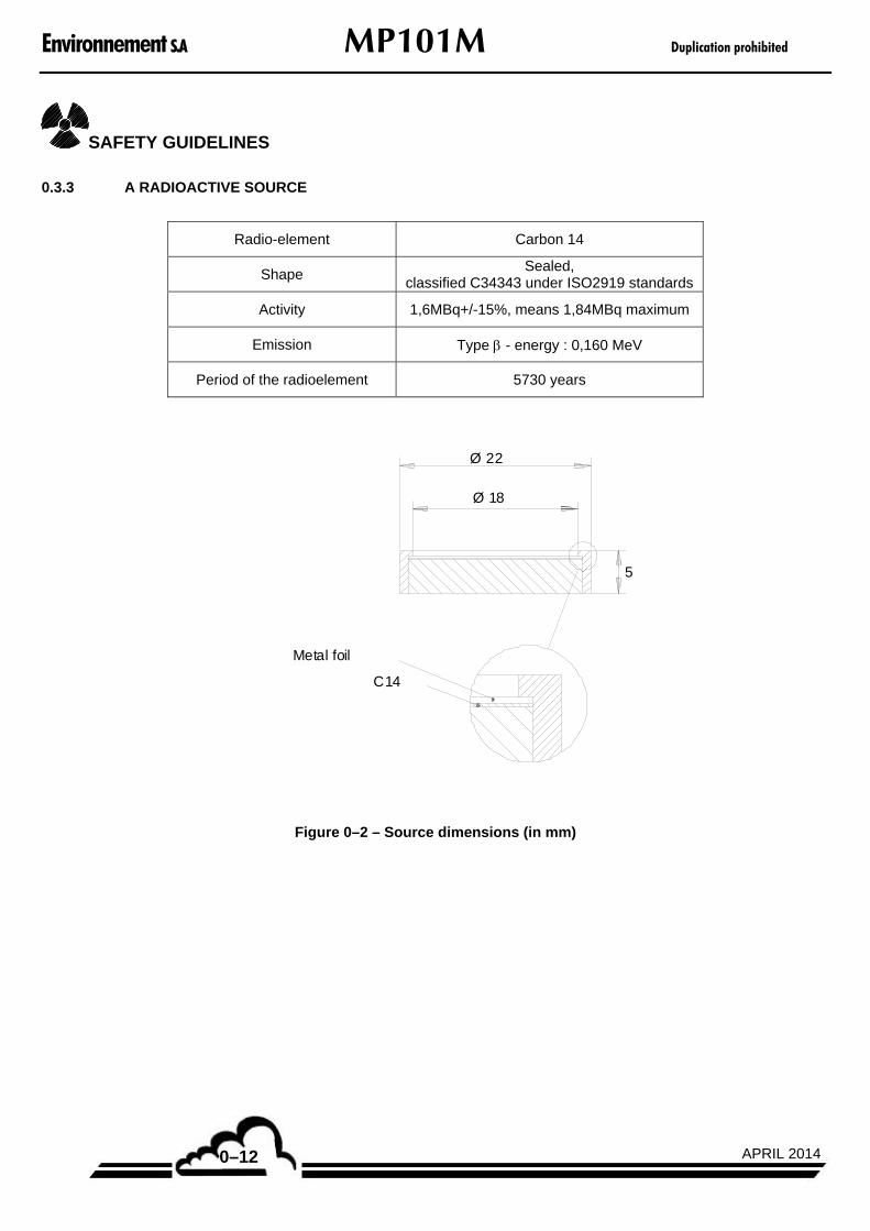
0.3.3 A RADIOACTIVE SOURCE
Radio-element Carbon 14
Shape Sealed,
classified C34343 under ISO2919 standards
Activity 1,6MBq+/-15%, means 1,84MBq maximum
Emission Type - energy : 0,160 MeV
Period of the radioelement 5730 years
Metal foil
C14
Ø 22
Ø 18
5
Figure 0–2 – Source dimensions (in mm)
Duplication prohibited MP101M Environnement S.A
0–13SEPTEMBER 2013
SAFETY GUIDELINES
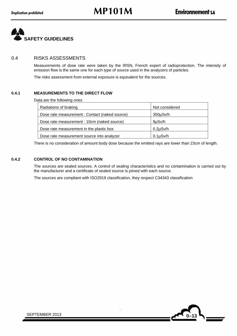
0.4 RISKS ASSESSMENTS
Measurements of dose rate were taken by the IRSN, French expert of radioprotection. The intensity of emission flow is the same one for each type of source used in the analyzers of particles.
The risks assessment from external exposure is equivalent for the sources.
0.4.1 MEASUREMENTS TO THE DIRECT FLOW
Data are the following ones
Radiations of braking Not considered
Dose rate measurement : Contact (naked source) 350µSv/h
Dose rate measurement : 10cm (naked source) 9µSv/h
Dose rate measurement in the plastic box 0.2µSv/h
Dose rate measurement source into analyzer 0.1µSv/h
There is no consideration of amount body dose because the emitted rays are lower than 23cm of length.
0.4.2 CONTROL OF NO CONTAMINATION
The sources are sealed sources. A control of sealing characteristics and no contamination is carried out by the manufacturer and a certificate of sealed source is joined with each source.
The sources are compliant with ISO2919 classification, they respect C34343 classification

Environnement S.A MP101M Duplication prohibited
SEPTEMBER 20130–14
SAFETY GUIDELINES
0.5 RISK ANALYSES
The equivalents of maximum permissible dose laid down by French regulations are given in the here-below table. The values are extracted from the public health laws (Labour and Public Health Rules).
According to the French labour laws, a worker is told exposed if, because of his professional activity, he is submitted to ionizing radiations likely to involve doses superior to the levels presented here-below.
Exposed zone Limit of equivalent dose
Global exposure 1 mSv/ year
Crystalline lens 15 mSv/ year
Skin 50 mSv/ year in average value for any surface of 1cm²
0.5.1 EXTERNAL EXPOSURE
When the analyzer is working, and even when the analyzer is not working, there is no direct access to the source. Under normal conditions of analyzers use, there is no possible irradiation. Indeed, because of the radiation type, there is no possible external exposure for the whole body (radiations have a distance lower than 23cm).
Consequently, the sources handling only occur when the source is put in place into the analyzer, and when the source is put out of the analyzer at the end of the source use.
The sources handling can only be carried out by people qualified and trained to this kind of sources and to their specific dangers. The technician must wear gloves.
For hands, in contact with the window of measurement, we can consider a dose rate of 0, 1µSv/h. To exceed the regulatory threshold of 50000µSv per year, the technician should leave his hands in contact with the window of measurement of the analyzer during more than 500 000 hours per year, which is realistic. Therefore, the values are very much lower than flows of tolerable for the public.
NOTA : to value the received dose, the dosimetric films are inoperative because insensitive to Beta radiations of low energy.
0.5.2 INTERNAL EXPOSURE
The internal exposure corresponds to the ingestion or the inhalation of radioactive materials.
According to the appendices of directive Euratom 96/29, the effective dose engaged by ingestion for the 14C is 5,8.10-10 Sv/Bq. To exceed the threshold of 1 mSv/an (total exposure), it would be necessary to eat one 14C source per year (for source of 1,6MBq)
These situations are obviously completely improbable. In normal condition of use the probability of inhaling radioactive dusts is very low: the sources are sealed into a closed analyzer.
Assessments by French Radioprotection Expert, IRSN, was made, they confirmed that the level of internal exposure is considered negligible and radiation doses are well below regulatory limits.
In normal use, the personnel, using MP101M, is not defined as exposed worker, and is not classified into category A or B. The acceptable exposure values are those valid for the public.
In practice, there is neither protected area (it would be located in contact with the outlet window which is inaccessible), nor controlled area.
Duplication prohibited MP101M Environnement S.A
0–15SEPTEMBER 2013
SAFETY GUIDELINES
0.6 RADIATION PROTECTION RECOMMENDATIONS
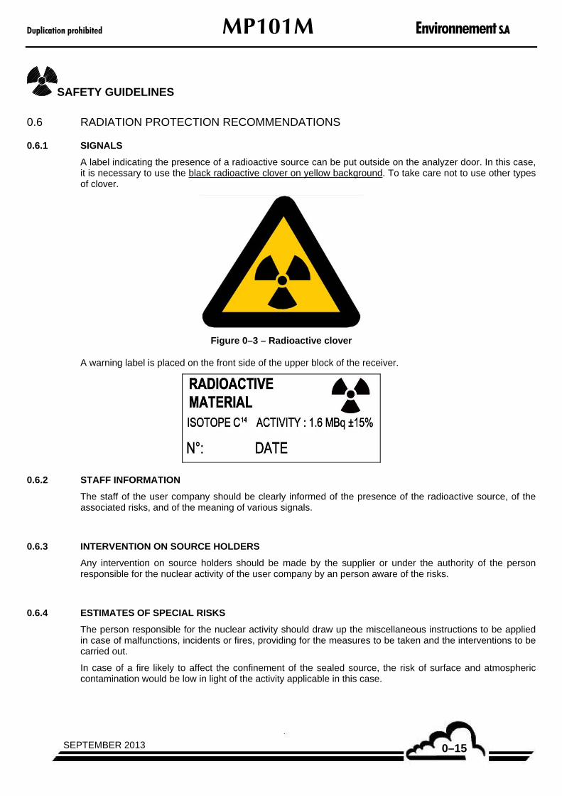
0.6.1 SIGNALS
A label indicating the presence of a radioactive source can be put outside on the analyzer door. In this case, it is necessary to use the black radioactive clover on yellow background. To take care not to use other types of clover.
Figure 0–3 – Radioactive clover
A warning label is placed on the front side of the upper block of the receiver.
0.6.2 STAFF INFORMATION
The staff of the user company should be clearly informed of the presence of the radioactive source, of the associated risks, and of the meaning of various signals.
0.6.3 INTERVENTION ON SOURCE HOLDERS
Any intervention on source holders should be made by the supplier or under the authority of the person responsible for the nuclear activity of the user company by an person aware of the risks.
0.6.4 ESTIMATES OF SPECIAL RISKS
The person responsible for the nuclear activity should draw up the miscellaneous instructions to be applied in case of malfunctions, incidents or fires, providing for the measures to be taken and the interventions to be carried out.
In case of a fire likely to affect the confinement of the sealed source, the risk of surface and atmospheric contamination would be low in light of the activity applicable in this case.
Environnement S.A MP101M Duplication prohibited
SEPTEMBER 20130–16
SAFETY GUIDELINES
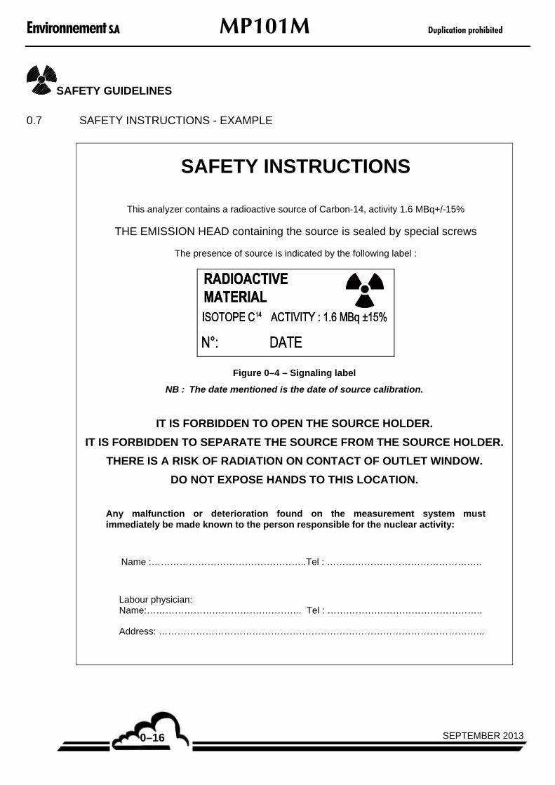
0.7 SAFETY INSTRUCTIONS - EXAMPLE
SAFETY INSTRUCTIONS
This analyzer contains a radioactive source of Carbon-14, activity 1.6 MBq+/-15%
THE EMISSION HEAD containing the source is sealed by special screws
The presence of source is indicated by the following label :
Figure 0–4 – Signaling label
NB : The date mentioned is the date of source calibration.
IT IS FORBIDDEN TO OPEN THE SOURCE HOLDER.
IT IS FORBIDDEN TO SEPARATE THE SOURCE FROM THE SOURCE HOLDER.
THERE IS A RISK OF RADIATION ON CONTACT OF OUTLET WINDOW.
DO NOT EXPOSE HANDS TO THIS LOCATION.
Any malfunction or deterioration found on the measurement system must immediately be made known to the person responsible for the nuclear activity:
Name :…………………………………………..Tel : …………………………………………..
Labour physician: Name:………………………………………….. Tel : …………………………………………..
Address: …………………………………………………………………………………………...

Duplication prohibited MP101M Environnement S.A
0–17SEPTEMBER 2013
SAFETY GUIDELINES
0.8 TECHNICAL CONTROLS OF RADIOPROTECTION
Environnement SA recommends to the users of the analyzers containing a radioactive source, to periodically carry out the technical checking of radioprotection, in particular :
Monthly checks, using, for instance, the Contamination Test described in the 4.3.10 sheet of chapter 4 of the technical manual of the analyzer.
Periodic radioprotection checks according to the regulation in-force in the country where the analyzer is used.
0.9 END OF LIFE OF THE ANALYZER
Refer to your local rules about end of life of radioactive material and electrical and electronic equipments.

Environnement S.A MP101M Duplication prohibited
SEPTEMBER 20130–18
Page intentionally left blank
Duplication prohibited MP101M Environnement S.A
1–1SEPTEMBER 2013
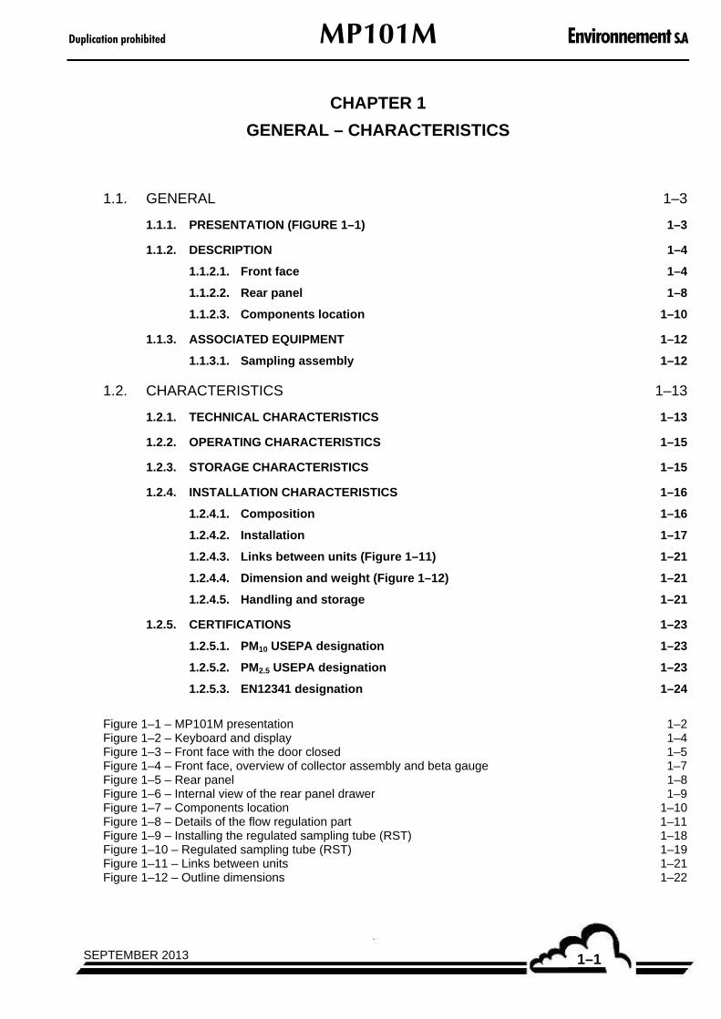
CHAPTER 1
GENERAL – CHARACTERISTICS
1.1. GENERAL 1–3
1.1.1. PRESENTATION (FIGURE 1–1) 1–3
1.1.2. DESCRIPTION 1–4
1.1.2.1. Front face 1–4
1.1.2.2. Rear panel 1–8
1.1.2.3. Components location 1–10
1.1.3. ASSOCIATED EQUIPMENT 1–12
1.1.3.1. Sampling assembly 1–12
1.2. CHARACTERISTICS 1–13
1.2.1. TECHNICAL CHARACTERISTICS 1–13
1.2.2. OPERATING CHARACTERISTICS 1–15
1.2.3. STORAGE CHARACTERISTICS 1–15
1.2.4. INSTALLATION CHARACTERISTICS 1–16
1.2.4.1. Composition 1–16
1.2.4.2. Installation 1–17
1.2.4.3. Links between units (Figure 1–11) 1–21
1.2.4.4. Dimension and weight (Figure 1–12) 1–21
1.2.4.5. Handling and storage 1–21
1.2.5. CERTIFICATIONS 1–23
1.2.5.1. PM10 USEPA designation 1–23
1.2.5.2. PM2.5 USEPA designation 1–23
1.2.5.3. EN12341 designation 1–24
Figure 1–1 – MP101M presentation 1–2 Figure 1–2 – Keyboard and display 1–4 Figure 1–3 – Front face with the door closed 1–5 Figure 1–4 – Front face, overview of collector assembly and beta gauge 1–7 Figure 1–5 – Rear panel 1–8 Figure 1–6 – Internal view of the rear panel drawer 1–9 Figure 1–7 – Components location 1–10 Figure 1–8 – Details of the flow regulation part 1–11 Figure 1–9 – Installing the regulated sampling tube (RST) 1–18 Figure 1–10 – Regulated sampling tube (RST) 1–19 Figure 1–11 – Links between units 1–21 Figure 1–12 – Outline dimensions 1–22
Environnement S.A MP101M Duplication prohibited
SEPTEMBER 20131–2
1. GENERAL – CHARACTERISTICS
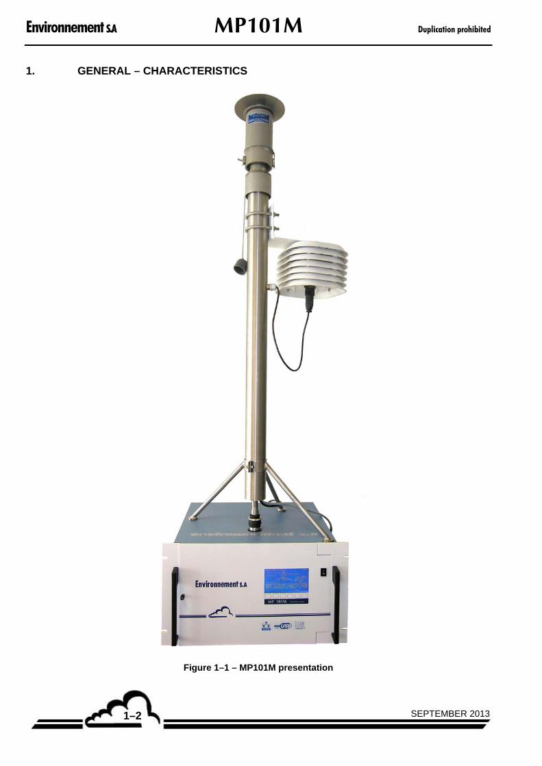
Figure 1–1 – MP101M presentation
Duplication prohibited MP101M Environnement S.A
1–3APRIL 2014
1.1. GENERAL
1.1.1. PRESENTATION (FIGURE 1–1)
The MP101M system is used to measure suspended particulate matter in the ambient air. Sampled air can also be monitored continuously for possible natural radioactivity, with programmed alarm in the event of a threshold overshoot.
The system is available in the form of an indoor cabinet for installation in a closed room, or an outdoor, heated and ventilated enclosure. This monitor can operate separately or be included into supervision and warning networks.
The MP101M is a particles measuring device using Beta gauge. The suspended particles are gathered by sampling a defined volume of air on a glass fiber filter. The filter is automatically unrolled between the Beta source and a Geiger-Müller counter (GM) according to defined sequences.
The difference in the radiation counting before and after gathering of the particles represents the measurement of the mass on the filter. Sampling is carried out with a vacuum pump through a sampling head connected to the top of the analyzer.
The MP101M provides many advantages, due to its technical design:
flexibility in use due to the multitasks interactive software,
presence of an upgradeable ARM7 board.
The Carbon 14 (14C) radioelement contained in the source has low-intensity and a long half-life of about 5730 years.
The filter ribbon used allows for a high number of sampling events (1200).
By the high-reliability of its components and its ease of use, the MP101M requires very limited maintenance.

Environnement S.A MP101M Duplication prohibited
SEPTEMBER 20131–4
1.1.2. DESCRIPTION
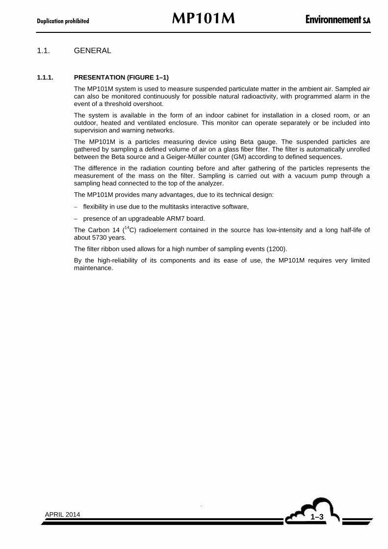
1.1.2.1. Front face
Refer to Figure 1–2 and Figure 1–3.
The front panel of the analyzer is formed by a fixed part and a hinged door giving access to the collector and Beta gauge assembly.
The door swivels left-to-right on its hinge pin and is locked by a quarter-turn knob on the left side.
The following components are mounted on the door
A main power supply "I/O" switch for ON-OFF control, located at the top-right corner.
a backlit liquid crystal display
16 lines x 40 columns (240 x 128 pixels)
the display provides the measurement values according to the selected unit, together with the information required for programming and testing the unit.
a keyboard with 6 touch-sensitive keys
The controls and checkings of the monitor are done using the keyboard.
The function of each key varies with the different screens or menus.
Figure 1–2 – Keyboard and display
Duplication prohibited MP101M Environnement S.A
1–5SEPTEMBER 2013
Figure 1–3 – Front face with the door closed

Environnement S.A MP101M Duplication prohibited
SEPTEMBER 20131–6
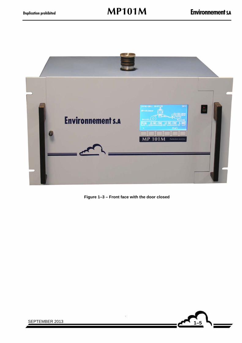
Door open (Figure 1–4) :
The door is opened by turning the locking knob clockwise.
The following components are then accessible :
– The reference gauge (1)
The reference gauge is located in a specific housing protected from dust.
Its surface density is determined in laboratory by gravimetric weighing.
The reference gauge is used for calibrating and checking the Beta gauge.
– The filter ribbon drive system, comprising:
a pay-out reel (10),
a take-up reel (7),
a capstan (5) coupled to the synchronous feed motor,
a disengageable pinch roller (6).
– The Beta gauge
The Beta gauge consists of a Carbon 14 radioactive source (14C) located in a source holder (3) in which the source can take two positions: – Out of the channel, when system is drawing in air (sampling) or shut down, – In front of the Geiger counter, for measurements of beta particles.
Geiger-Müller tube detector (8), located on the same axis, downstream of the ribbon.
In measurement mode, the source and G.M counter always maintain the same relative positions regardless of the operations performed on the device (translation of pressure assembly, ribbon feed, positioning of a reference gauge) in order to ensure the same counting conditions in all cases.
– Gas transport system
A flexible channel (4) with knurled knob for connection of the sampling head.
The flexible channel can be retracted for installation of a fixed head,
or unscrewed for use of a telescopic head.
A 16 mm diameter cylindrical conduit made of stainless steel. This conduit channels the gases sampled to the glass fibre filter (filter ribbon) with no obstacles, thus ensuring uniformity of the particle deposit.
A pressure assembly (9), maintaining the filter against the source block during measurements. Tightness of the system is ensured by the pressure assembly (9) and a clamping grille located above the G.M counter.
Duplication prohibited MP101M Environnement S.A
1–7SEPTEMBER 2013
(1) reference gauge, (3) source holder, (4) flexible channel, (5) capstan, (6) disengageable pinch roller, (7) take-up reel, (8) Geiger-Müller tube detector, (9) pressure assembly, (10) pay-out reel.
Figure 1–4 – Front face, overview of collector assembly and beta gauge

Environnement S.A MP101M Duplication prohibited
SEPTEMBER 20131–8
1.1.2.2. Rear panel
Refer to Figure 1–5.
The rear panel of the MP101M contains the electrical connectors and the air outlet connector. It is designed as a drawer containing various mechanical elements on its internal part.
– Air outlet (bottom-left side)
The "pump outlet" for connection to the external vacuum pump consists of an 8 mm diameter straight connection fitting (8).
– Electrical equipment and connections
The electrical (mains) power supply assembly consists of a 3-contact socket for connection of a standard power cable; it contains two time-delay fuse of 3.15 A / 220 V or 5 A / 115 V (1).
One 25-pin connector for the serial link (RS232/RS422) (4).
One 3-contact TUCHEL connector for 24 V CC supply of the sampling head heating (3).
One external pump power supply connector (5).
One 15-pin socket for link with the ambient air sensor (6),
One TCP/IP network socket (7).
One socket for CPM link (11).
Two slots for the ESTEL board options (10)
– Ventilation system
The ventilation system consists of a fan integrated in the rear panel (2) for ventilation of the electrical and electronic circuits.
(1) general fuse F1 and electrical (mains) power supply block, (2) fan, (3) TUCHEL connector for heating of sampling head inlet, (4) RS232/RS422 plug, (5) power supply of external pump, (6) ambient air sensor, (7) TCP/IP socket, (8) pump outlet, (9) holding screws of the cover, (10) ESTEL board option, (11) connection socket with the CPM option, (12) holding screws of the rear panel drawer.
Figure 1–5 – Rear panel
Duplication prohibited MP101M Environnement S.A
1–9SEPTEMBER 2013
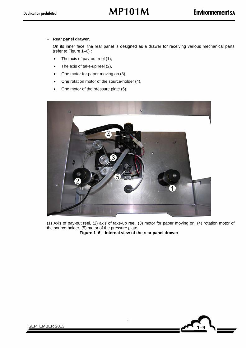
Rear panel drawer.
On its inner face, the rear panel is designed as a drawer for receiving various mechanical parts (refer to Figure 1–6) :
The axis of pay-out reel (1),
The axis of take-up reel (2),
One motor for paper moving on (3),
One rotation motor of the source-holder (4),
One motor of the pressure plate (5).
(1) Axis of pay-out reel, (2) axis of take-up reel, (3) motor for paper moving on, (4) rotation motor of the source-holder, (5) motor of the pressure plate.
Figure 1–6 – Internal view of the rear panel drawer

Environnement S.A MP101M Duplication prohibited
SEPTEMBER 20131–10
1.1.2.3. Components location
Refer to Figure 1–7.
The components inside the unit are accessed by simply unscrewing the knurled knobs (Rep. 9, Figure 1–5) at the rear of the unit and removing the upper cover.
The housing is divided into three parts, separated by two aluminium plates:
the flow regulation part (1),
the collector and Beta gauge assembly at the front of the unit (2),
the electronics part (3) composed of
the module board (4),
the power supply board (6).
NOTE : – the Arm7 board (5) is located behind the display and linked to the module board with a suitable cable.
(1) Flow regulation part, (2) collector and Beta gauge assembly, (3) electronics part, (4) Module board, (5) ARM7 board, (6) power supply board.
Figure 1–7 – Components location
Duplication prohibited MP101M Environnement S.A
1–11SEPTEMBER 2013
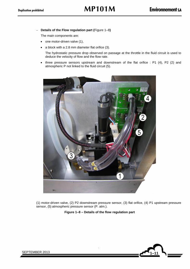
– Details of the Flow regulation part (Figure 1–8)
The main components are:
one motor-driven valve (1),
a block with a 2.8 mm diameter flat orifice (3).
The hydrostatic pressure drop observed on passage at the throttle in the fluid circuit is used to deduce the velocity of flow and the flow rate.
three pressure sensors upstream and downstream of the flat orifice : P1 (4), P2 (2) and atmospheric P not linked to the fluid circuit (5).
(1) motor-driven valve, (2) P2 downstream pressure sensor, (3) flat orifice, (4) P1 upstream pressure sensor, (5) atmospheric pressure sensor (P. atm.).
Figure 1–8 – Details of the flow regulation part

Environnement S.A MP101M Duplication prohibited
SEPTEMBER 20131–12
1.1.3. ASSOCIATED EQUIPMENT
– Sampling assembly,
– Pump assembly,
– Recorders, PC (optional)
1.1.3.1. Sampling assembly
See section 1.2.5.
It consists of :
– A standard sampling head, interchangeable according to application :
TSP,
PM10 US EPA* or EN12341
PM2,5 US EPA** or EN14907
PM1
(*) : as specified in the 40CFR 50, appendix L paragraph 7.3.2 « The sample inlet shall be fabricated as indicated in Figures L-2 through L-18 of this appendix and shall meet all associated requirements ».
(**) : as specified in the 40 CFR 50, appendix L paragraph 7.3.2 and 7.3.4.4. « The cyclone-type separator is identified as a BGI VSCCTM Very Sharp Cut Cyclone particle size separator specified as part of EPA-designated equivalent method EQPM-0202-142 (67 FR 15567, April 2, 2002 ».
– A regulated sampling tube (RST)***, stainless steel sampling conduit comprising:
A heating ribbon,
A 60 mm diameter stainless steel tube protecting the sampling conduit,
Two flanges and a seal for tightness with respect to the outside.
A meterological sensor composed of a temperature probe and a humidity probe.
A regulated sampling tube (RST) channel available in several lengths : 1 m, 1.50 m, 2 m, 2.75 m or more subject to special study.
(***) : standard for USEPA equivalencies
Duplication prohibited MP101M Environnement S.A
1–13APRIL 2014
1.2. CHARACTERISTICS
1.2.1. TECHNICAL CHARACTERISTICS
Measurement principle : Cyclic measurement by Beta rays gauge
Type of measurement and units : – Density deposited in µg/cm2 – Concentration in µg/m3
Units of flow : l/mn, m3/h
Units of volume : litres, m3, Nm3, Sm3 (at 20°C and 25°C)
Form of results on concentration – Cyclic measurements : – Periodic
– Average – Floating average
Geiger-Müller counting time : Programmable from 10 to 200 s
Scan periods : 10 mn, 1/4 - 1/2 - 1 - 2 - 3 - 4 – 6 - 12 – 24 – 48 hours
Measurement cycles : 1 - 2 - 3 – 4 - 6 - 12 - 24 - 48 - 72 - 96 hours
Measurement threshold : Depends on periods, cycles and flow rates selected for 24-hour cycle and flow rate of 1 m3/h: 0.5 µg/m3
Noise ( with Tc = 200 s) : 3 µg/cm2 on one period of 2 h (PM10).
Minimum detectable limit : 6 µg/cm2 on one period of 2h (PM10) (2 with Tc = 200 s)
Beta source : Carbone 14 radioelement, half-life of radioelement 5730 ans
Gauge adjustment : Automatic on each cycle change
Calibration : By reference gauge

Environnement S.A MP101M Duplication prohibited
SEPTEMBER 20131–14
Concentration measurement range on one period:
Duration of scan period
Minimum detectable concentration
in µg/m3 on one period
in hours 1 m3/h flow rate
1/4 1/2 1 2 3
48 24 12 6 4
Concentration measurement range on one cycle :
Duration of cycle in hours
Minimum detectable concentration
in µg/m3 on one cycle
1 m3/h flow rate
6 12 24
2 1
0.5
Sampling rate : 1 m3/h
Spot area : 2.4 cm2
Step between two spots : 23 mm
Standard filter ribbon : Ribbon width = 35 mm, length = 30 m. Glass fiber filter.
Capacity : 1200 samplings, representing more than 3 years at a rate of one spot per 24 hours
External pump : Vacuum pump with two flat diaphragm heads, or impeller pump
Display : LCD
Control keypad : 6 keys

Duplication prohibited MP101M Environnement S.A
1–15SEPTEMBER 2013
Output signals : up to 8 analog outputs (programmable full scale ) 0-1 V, 0-10 V, 0-20 mA, or 4-20 mA with galvanic isolator on option (depending on the number of ESTEL boards option present)
Power supply : 230 V-50 Hz (115 V-60 Hz on request) + ground
Consumption : Without pump: 350 mA With pump: 1500 mA
Maximum active power : 200 VA consumed by pump
Power of unit : 300 VA
Operating temperature : + 10 °C to + 40 °C
Alarm checks : – Permanent – Detection and indication of malfunctions: temperature,
pressure, flow rates, electric parameters.
Tests and diagnostics for maintenance : Selection on keyboard and display of all parameters.
Back-up saving time for data stored in FLASH : unlimited and of real-time clock: : 2 years by built-in battery
1.2.2. OPERATING CHARACTERISTICS
Refer to Chapter 0, Safety Guidelines section, pages 0-10 to 0-18
1.2.3. STORAGE CHARACTERISTICS
– Temperature: – 10 °C to 60 °C.
– This model uses a rotary source holder. The Carbon 14 source can thus take two positions: storage and emission.
Environnement S.A MP101M Duplication prohibited
SEPTEMBER 20131–16
1.2.4. INSTALLATION CHARACTERISTICS
The MP101M monitor can be integrated in a standard cabinet for installation indoors or in a sealed enclosure for use outdoors.
1.2.4.1. Composition
a) MP101M standard cabinet
This is a standard 19-inch cabinet designed to receive 32 "deep" units (useful depth = 750 mm).
The cabinet comprises:
– 1 sliding panel,
– 1 pump unit,
– 4 fans (upper part),
– 1 tangential fan (lower part),
– 1 differential circuit breaker with 5 electrical distribution connectors,
– 1 power supply terminal board with fuse holder,
– 1 connection terminal board (inputs/outputs, analog signals),
– 1 rear door with key lock.
Optional: Glazed front door with key lock.
b) MP101M EX sealed box
This box consists of a reinforced polyester box designed to protect the MP101M and its subassemblies against weather (protection IP559, standard NF C20010).
It comprises:
– 1 interior base plate, made of aluminium,
– 1 pump mounting plate,
– 2 side fans,
– 2 air inlets,
– 1 heating system with thermostat.

Duplication prohibited MP101M Environnement S.A
1–17SEPTEMBER 2013
– 1 differential circuit breaker with 4 electrical distribution connectors,
– 1 power supply terminal board with fuse holder,
– 1 connection terminal board (inputs/outputs and analog signals),
– 1 front door,
– 1 rear door,
NOTE: The doors are locked by a 3-point casement bolt, locked by a handle with key lock.
– 1 external stainless steel stiffener for the sampling head,
– 2 stainless steel legs for attachment of the enclosure.
Heating system
The housing is heated by a 500 W electrical resistor coupled to one of the fans. The temperature is regulated by a thermostat (range: 0 to 30 °C) associated to a safety switch (cut-out at 60 °C).
1.2.4.2. Installation
a) Installation outdoors
a.1) Concrete base
For outdoor installation of the sealed box, a concrete slab (2 m x 1 m) is required.
The minimum height of the base (to protect it against water) will be selected according to the field conditions.
A passage must be provided in the base for the electrical power supply and for other cables which may be required for remote control, telephone link, etc.
Four diameter M10 threaded rods protruding by 0.10 m must be embedded in the concrete slab to receive the stainless steel legs on which the housing is mounted.
a.2) Installing the MP101M
The MP101M is set on the aluminium base plate and blocked by inserting the studs of the rear legs into the holes provided for this purpose on the mounting plate.

Environnement S.A MP101M Duplication prohibited
SEPTEMBER 20131–18
a.3) Installing the regulated sampling tube (RST)
Place the sampling head in its housing and adjust the height to ensure tightness between the head channel and the channel of the MP101M, without crushing it (see diagram below).
Sampling head
Sampling head channel
MPM101M "flexible" channel
Gasket, compressed
Gasket of tightness (head/MP101M link)
Do not crush MP101M channel with head. The channel should remain flexible to enable disengaging the MP101M from its head
Block sampling head with flanges provided for this purpose (external flange + internal flange).
CAUTION: DO NOT FORGET TO ENSURE TIGHTNESS ON TOP OF BOX USING CLAMP PROVIDED WITH ASSEMBLY (see diagram below).
Figure 1–9 – Installing the regulated sampling tube (RST)
Duplication prohibited MP101M Environnement S.A
1–19SEPTEMBER 2013
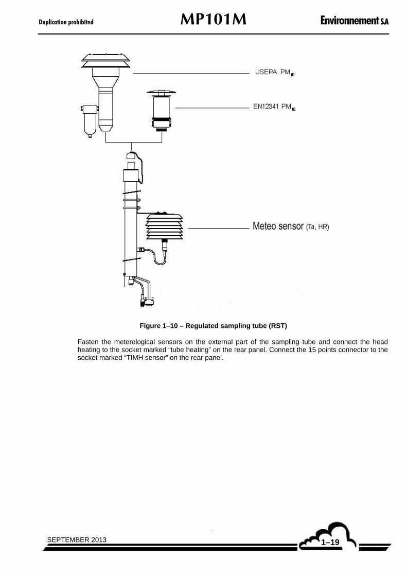
Figure 1–10 – Regulated sampling tube (RST)
Fasten the meterological sensors on the external part of the sampling tube and connect the head heating to the socket marked “tube heating” on the rear panel. Connect the 15 points connector to the socket marked “TIMH sensor” on the rear panel.

Environnement S.A MP101M Duplication prohibited
SEPTEMBER 20131–20
a.4) Electrical connections
– The unit is connected to the electrical system through the power supply terminal board (see electrical diagram).
– The sampling head must be grounded (use tapped hole provided for this purpose at lower end of head).
– Connect the sampling head heating system to the MP101M (connector on MP101M rear panel marked "tube heater").
b) Installation indoors
b.1) Installing the sampling head
Once the location for the standard cabinet has been defined, a passage must be provided, by a specialist, in the ceiling of the room, directly above the bay orifice to enable installing the sampling head.
IMPORTANT: SPECIAL CARE MUST BE TAKEN TO ENSURE TIGHTNESS AROUND THE ORIFICE AT THE TOP OF THE CABINET. LEAKS COULD CAUSE DAMAGE TO THE ANALYZER.
For this reason, the installation must enable to use the two flanges and the tightness gasket provided with the head.
The head must be able to slide, in order to match up, with no difficulty, with the sampling conduit of the MP101M (see Figure 1–9).
NOTE: It is highly recommended to provide a system for securing the head in position to prevent it from moving downward and bearing on the MP101M box. In all cases, the head must remain easily removable for maintenance purposes, for example.
b.2) Electrical connection
– The unit is connected to the electrical system through the power supply terminal board (see electrical diagram).
– The sampling head must be grounded (use tapped hole provided for this purpose at lower end of head).
– Connect the sampling line heating plug to the MP101M (socket on MP101M rear panel marked “tube heating”.)
Note: For indoor installation outside the cabinet, a system must be provided to secure the sampling head in position at two points (top and bottom), AS WELL AS A SYSTEM FOR GROUNDING THE SAMPLING HEAD. A means for securing the pump to the ground must also be provided.
Duplication prohibited MP101M Environnement S.A
1–21SEPTEMBER 2013
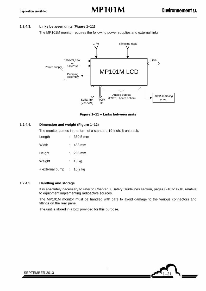
1.2.4.3. Links between units (Figure 1–11)
The MP101M monitor requires the following power supplies and external links :
MP101M LCD
Serial link(V21/V24)
230V/3,15Aor
115V/5A
Dust samplingpump
Sampling head
Power supply
Pumpingassembly
Analog outputs(ESTEL board option)
TCP/IP
USB
CPM
Figure 1–11 – Links between units
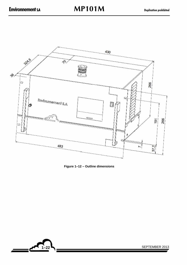
1.2.4.4. Dimension and weight (Figure 1–12)
The monitor comes in the form of a standard 19-inch, 6-unit rack.
Length : 360,5 mm
Width : 483 mm
Height : 266 mm
Weight : 16 kg
+ external pump : 10,9 kg
1.2.4.5. Handling and storage
It is absolutely necessary to refer to Chapter 0, Safety Guidelines section, pages 0-10 to 0-18, relative to equipment implementing radioactive sources.
The MP101M monitor must be handled with care to avoid damage to the various connectors and fittings on the rear panel.
The unit is stored in a box provided for this purpose.
Environnement S.A MP101M Duplication prohibited
SEPTEMBER 20131–22
Figure 1–12 – Outline dimensions

Duplication prohibited MP101M Environnement S.A
1–23SEPTEMBER 2013
1.2.5. CERTIFICATIONS
1.2.5.1. PM2.5 USEPA designation
The PM2.5 automatic analyzer of particles, MP101M model, is nominated USEPA equivalent method as defined by the code of federal laws CFR 40, Part 53, when it operates under the following conditions:
1. Use of a sampling head specified in the 40 CFR 50, appendix L paragraph 7.3.2** and 7.3.4.4*** or in the previous model “flat-topped 246b”.
2. Use of the RST* sampling tube is required.
3. Use of the following configuration:
Parameter Value Paragraph of the manual
Concentration unit µg/m3 3.3.4.4
Flow unit l/min 3.3.4.4
Cycle timing 24 h 3.3.4.2
Period timing 1 h 3.3.4.2
Counting (time) 0200 s 3.3.4.2
(Programmed) flow-rate 1.00 m3/h 3.3.4.2
N.R.A counting OFF 3.3.4.2
RST ON 3.3.4.2
(*) RST : regulated sampling tube
(**) : 7.3.2 Inlet. The sample inlet shall be fabricated as indicated in Figures L-2 through L-18 of this appendix and shall meet all associated requirements.
(***) : 7.3.4.4 The cyclone-type separator is identified as a BGI VSCCTM Very Sharp Cut Cyclone particle size separator specified as part of EPA-designated equivalent method EQPM-0202-142 (67 FR 15567, April 2, 2002).

Environnement S.A MP101M Duplication prohibited
SEPTEMBER 20131–24
1.2.5.3. EN12341 designation
The PM10 automatic analyzer of particles, MP101M model, is certified EN12341, when it operates under the following conditions :
1. Use of a sampling head equipped with a fractionation (screening) device equivalent to the EN12341, and with a reference tube RST*100, RST*150 or RST* 200 consisting of a temperature and humidity sensor.
(*) RST : regulated sampling tube

Duplication prohibited MP101M Environnement S.A
2–1SEPTEMBER 2013
CHAPTER 2
PRINCIPLE OF OPERATION
2.1. BETA GAUGE PRINCIPLE (FIGURE 2–1 AND FIGURE 2–2) 2–3
2.2. FLOW REGULATION PRINCIPLE 2–6
2.3. ACQUISITION AND PROCESSING OF MEASUREMENT PARAMETERS 2–8
2.4. ORGANIZATION OF MEASUREMENTS 2–8
2.5. REGULATED SAMPLING TUBE (RST) 2–11
Figure 2–1 – General functional diagram 2–2 Figure 2–2 – Beta gauge 2–3 Figure 2-3 – Flow regulation diagram 2–6 Figure 2-4 - Organisation of measurements 2–8 Figure 2–5 – Regulated sampling tube (RST) line assembly 2–12
Environnement S.A MP101M Duplication prohibited
SEPTEMBER 20132–2
2. PRINCIPLE OF OPERATION
Sampling head
Sample tube
Filter
Vacuum pump
Flow regulation device
Emiterunit
Receiverunit
Betagauge
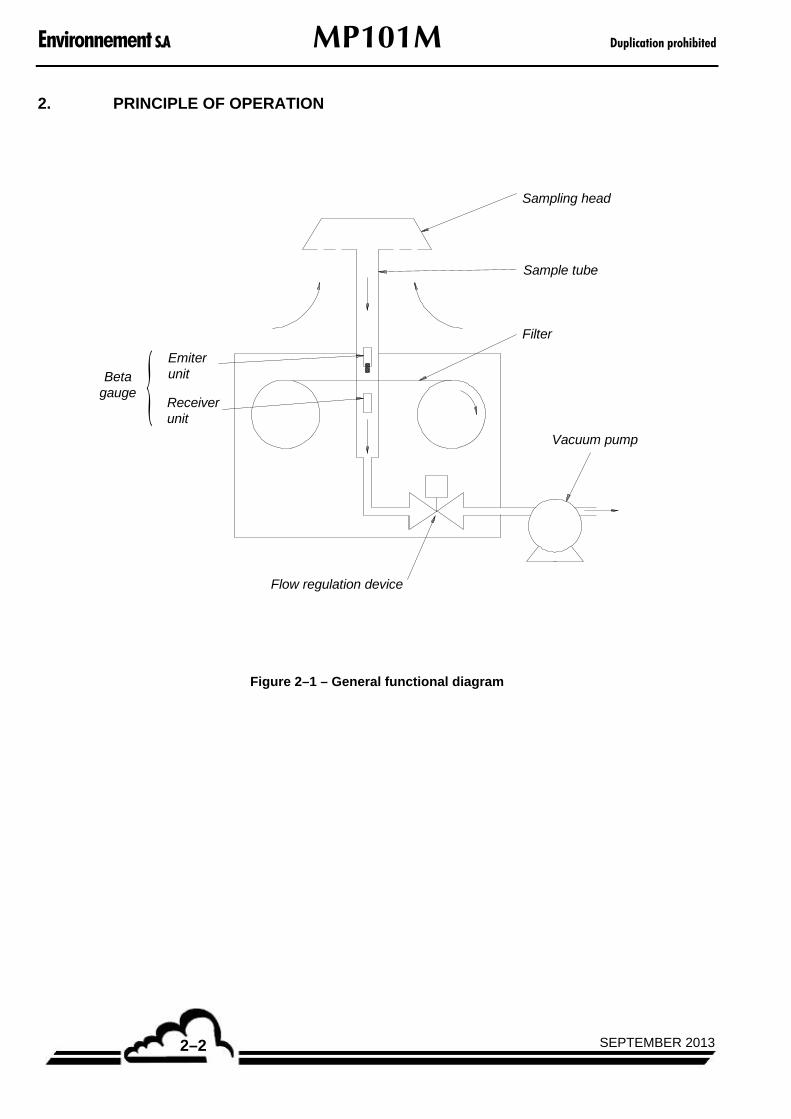
Figure 2–1 – General functional diagram
Duplication prohibited MP101M Environnement S.A
2–3APRIL 2014
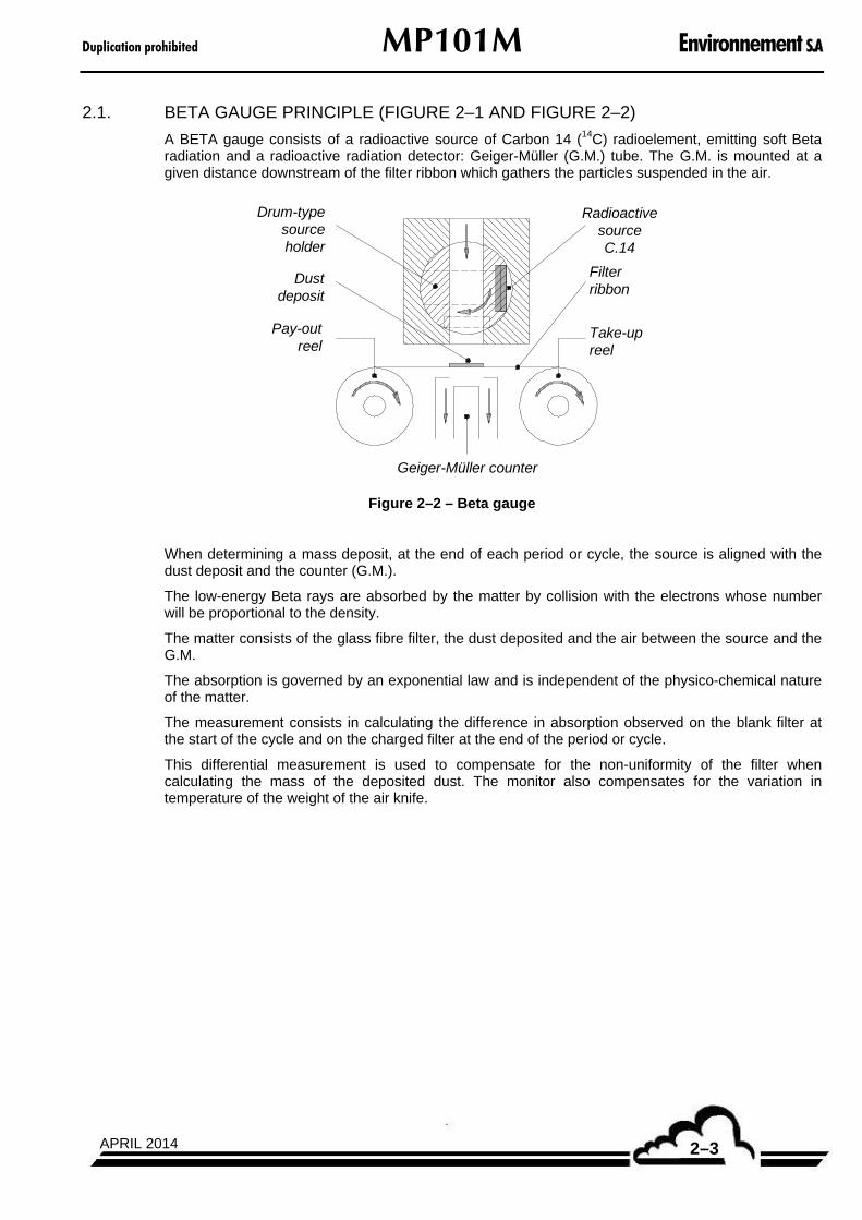
2.1. BETA GAUGE PRINCIPLE (FIGURE 2–1 AND FIGURE 2–2)
A BETA gauge consists of a radioactive source of Carbon 14 (14C) radioelement, emitting soft Beta radiation and a radioactive radiation detector: Geiger-Müller (G.M.) tube. The G.M. is mounted at a given distance downstream of the filter ribbon which gathers the particles suspended in the air.
Drum-typesourceholder
Dustdeposit
Pay-outreel
RadioactivesourceC.14
Filterribbon
Take-upreel
Geiger-Müller counter
Figure 2–2 – Beta gauge
When determining a mass deposit, at the end of each period or cycle, the source is aligned with the dust deposit and the counter (G.M.).
The low-energy Beta rays are absorbed by the matter by collision with the electrons whose number will be proportional to the density.
The matter consists of the glass fibre filter, the dust deposited and the air between the source and the G.M.
The absorption is governed by an exponential law and is independent of the physico-chemical nature of the matter.
The measurement consists in calculating the difference in absorption observed on the blank filter at the start of the cycle and on the charged filter at the end of the period or cycle.
This differential measurement is used to compensate for the non-uniformity of the filter when calculating the mass of the deposited dust. The monitor also compensates for the variation in temperature of the weight of the air knife.
Environnement S.A MP101M Duplication prohibited
SEPTEMBER 20132–4
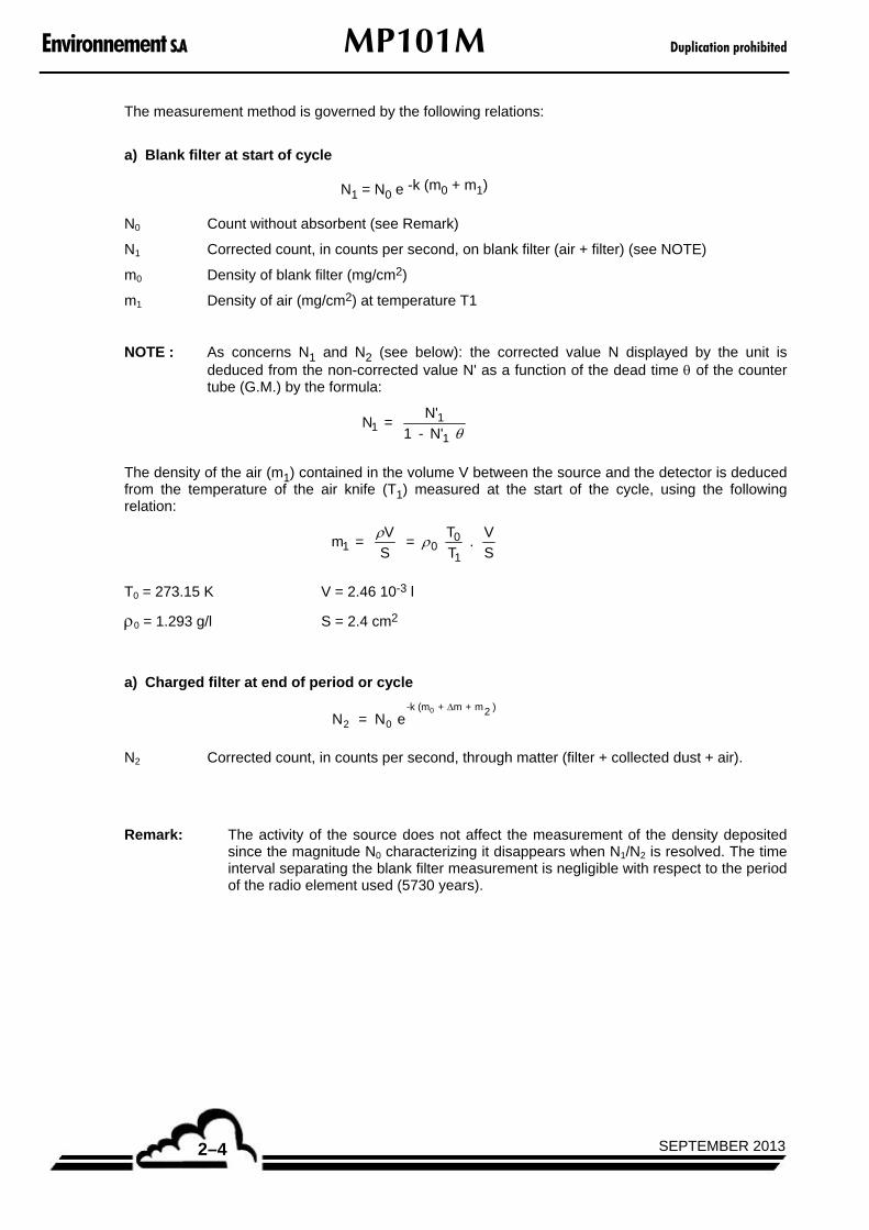
The measurement method is governed by the following relations:
a) Blank filter at start of cycle
N1 = N0 e -k (m0 + m1)
N0 Count without absorbent (see Remark)
N1 Corrected count, in counts per second, on blank filter (air + filter) (see NOTE)
m0 Density of blank filter (mg/cm2)
m1 Density of air (mg/cm2) at temperature T1
NOTE : As concerns N1 and N2 (see below): the corrected value N displayed by the unit is deduced from the non-corrected value N' as a function of the dead time of the counter tube (G.M.) by the formula:
N = N'
1 - N' 11
1
The density of the air (m1) contained in the volume V between the source and the detector is deduced from the temperature of the air knife (T1) measured at the start of the cycle, using the following relation:
m = V
S =
T
T .
V
S1 00
1
T0 = 273.15 K V = 2.46 10-3 l
0 = 1.293 g/l S = 2.4 cm2
a) Charged filter at end of period or cycle
N = N e2 0
-k (m + m + m20 )
N2 Corrected count, in counts per second, through matter (filter + collected dust + air).
Remark: The activity of the source does not affect the measurement of the density deposited since the magnitude N0 characterizing it disappears when N1/N2 is resolved. The time interval separating the blank filter measurement is negligible with respect to the period of the radio element used (5730 years).

Duplication prohibited MP101M Environnement S.A
2–5SEPTEMBER 2013
m Density of particles deposited.
m2 Density of air (mg/cm2) at temperature of T2
In the two relations a) and b), this gives:
N
N = e1
2
k ( m + m2 - m1)
and:
m + m - m = 1
k Ln 2 1
N
N1
2
which gives the final relation:
m = 1
k Ln + m - m1 2
N
N1
2
where k
1 depends on the nature of the radiation emitted by the source, as well as the absorption
properties of the ribbon filter.
NOTE : Refer also to sections 2.2 and 2.4 about the calculation of volumes and concentrations.

Environnement S.A MP101M Duplication prohibited
SEPTEMBER 20132–6
2.2. FLOW REGULATION PRINCIPLE
The sample is taken at a constant volume flow rate with compensation of load loss due to the filter and progressive depositing of dust.
The flow rate is therefore controlled and maintained at the selected reference value of 1.0 m3/h.
Commandand control
Motor
Externalpump
P1 P2
MP101M
Fluid flow direction
Figure 2-3 – Flow regulation diagram
P1 and P2 designate the absolute static pressures measured on both sides of the diaphragm through two axial holes perpendicular to the fluid flow direction and located very near the diaphragm.
The diaphragm is machined and arranged to produce a turbulent flow in the immediate vicinity. The
diameters of the conduit and orifice are sized such that, P
P2
1
> 0.9 in most cases, whereby the flow
can be considered as incompressible, minimizing load loss effects.

Duplication prohibited MP101M Environnement S.A
2–7SEPTEMBER 2013
The internal sensors of temperature and pressure coupled with the meterological sensors of regulated sampling tube (RST) line enable to measure the “volumetric” flow rate in the atmospheric conditions:
The flow rate is thus controlled and maintained constant to the nominal setting value (1 m3/h) at level of sampling head. That is essential in order to ensure the correct granulometric separation of the particles through the head and the precise calculation of sampled volume in atmospheric conditions.
The flow of a fluid through a critical orifice is given by the following equation, in case of an homogenous, not turbulent flow :
2
1
2
2
1*
2
S
S
PSQ
(1)
Where :
P = P1 – P2 is the difference between the pressures measured upstream and downstream the orifice,
S1 and S2 are the surfaces of the two orifice sections.
is the air density at P1 pressure and T1 temperature, with 1
0
0
10 **
T
T
P
P .
As S1, S2, P0 (reference pressure = 1013.33 mbar) and T0 (reference temperature = 273.15K) are constants, consequently it is possible to write the flow at level of the orifice flowrate (Qflowmeter) under the form :
1
1**
P
TPKQ flowmeter
(2)
Where K is a constant which is possible to define by calibration (in the « CALIBRATION Flow rate »).
Case when the regulated sampling tube (RST) option is activated :
The flow rate, into the atmospheric conditions, is automatically calculated by the analyzer, in the following way :
atm
atm
atm
atmatm P
T
T
PPK
P
T
T
P
P
TPKQ *
****
**
1
1
1
1
1
1
(3)
Where Tatm and Patm respectively are the temperature and the atmospheric pressure measured continuously.
NOTE : In the previous equations, the Tatm and T1 temperatures are stated in Kelvin degrees.
Environnement S.A MP101M Duplication prohibited
SEPTEMBER 20132–8
2.3. ACQUISITION AND PROCESSING OF MEASUREMENT PARAMETERS
The temperature and pressure sensor outputs are transmitted via an analog multiplexer with 16 input channels to the D/A converter on the Module board (4) in figure 1–7. The signals are converted into digital signals and sent to the microprocessor.
The microprocessor processes acquisition data, carries out calculations, automatisms, interfaces control.
The microprocessor receives the digital signal corresponding to count of the (G.M.) detection tube.
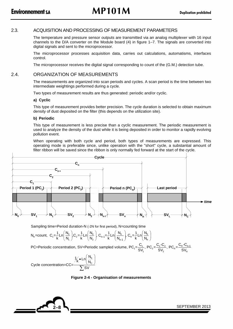
2.4. ORGANIZATION OF MEASUREMENTS
The measurements are organized into scan periods and cycles. A scan period is the time between two intermediate weightings performed during a cycle.
Two types of measurement results are thus generated: periodic and/or cyclic.
a) Cyclic
This type of measurement provides better precision. The cycle duration is selected to obtain maximum density of dust deposited on the filter (this depends on the utilization site).
b) Periodic
This type of measurement is less precise than a cyclic measurement. The periodic measurement is used to analyze the density of the dust while it is being deposited in order to monitor a rapidly evolving pollution event.
When operating with both cycle and period, both types of measurements are expressed. This operating mode is preferable since, unlike operation with the "short" cycle, a substantial amount of filter ribbon will be saved since the ribbon is only normally fed forward at the start of the cycle.
Period 1 (PC1) Period n (PCn)Period 2 (PC2)
Cn
N0 SV1 N2N1 SV2 SVnNn-1 Nn
C1
C2
Cn-1
time
Cycle
Last period
NCSVL
0 0 0 01 2
1 2n nn-1
nn-1
(-2N for first period), Sampling time=Period duration-N N=counting time
N N N N1 1 1 1N =count, C = Ln ,C = Ln , C = Ln , C = Ln
k N k N k N k N
PC=Periodic concentration, SV=Periodic
1 1 21 2
1 2
0
C
n n-1n
n
C -CC C -Csampled volume, PC = , PC = , PC =
SV SV SV
N1 Lnk NCycle concentration=CC=
SV
Figure 2-4 - Organisation of measurements
Duplication prohibited MP101M Environnement S.A
2–9SEPTEMBER 2013
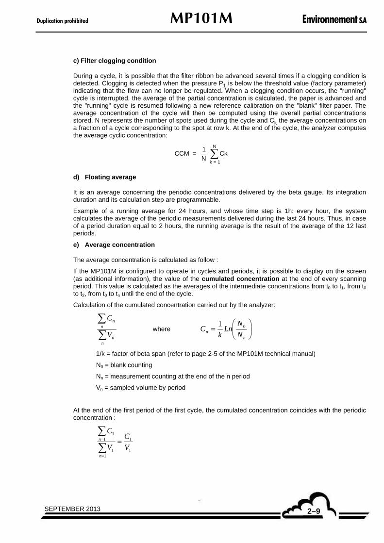
c) Filter clogging condition
During a cycle, it is possible that the filter ribbon be advanced several times if a clogging condition is detected. Clogging is detected when the pressure P1 is below the threshold value (factory parameter) indicating that the flow can no longer be regulated. When a clogging condition occurs, the "running" cycle is interrupted, the average of the partial concentration is calculated, the paper is advanced and the "running" cycle is resumed following a new reference calibration on the "blank" filter paper. The average concentration of the cycle will then be computed using the overall partial concentrations stored. N represents the number of spots used during the cycle and Ck the average concentrations on a fraction of a cycle corresponding to the spot at row k. At the end of the cycle, the analyzer computes the average cyclic concentration:
CCM = 1
N k = 1
N
Ck
d) Floating average
It is an average concerning the periodic concentrations delivered by the beta gauge. Its integration duration and its calculation step are programmable.
Example of a running average for 24 hours, and whose time step is 1h: every hour, the system calculates the average of the periodic measurements delivered during the last 24 hours. Thus, in case of a period duration equal to 2 hours, the running average is the result of the average of the 12 last periods.
e) Average concentration
The average concentration is calculated as follow :
If the MP101M is configured to operate in cycles and periods, it is possible to display on the screen (as additional information), the value of the cumulated concentration at the end of every scanning period. This value is calculated as the averages of the intermediate concentrations from t0 to t1, from t0 to t2, from t0 to tn until the end of the cycle.
Calculation of the cumulated concentration carried out by the analyzer:
nn
nn
V
C where
nn N
NLn
kC 01
1/k = factor of beta span (refer to page 2-5 of the MP101M technical manual)
N0 = blank counting
Nn = measurement counting at the end of the n period
Vn = sampled volume by period
At the end of the first period of the first cycle, the cumulated concentration coincides with the periodic concentration :
1
1
11
11
V
C
V
C
n
n

Environnement S.A MP101M Duplication prohibited
SEPTEMBER 20132–10
at the end of the next period, the cumulated concentration is given by :
21
21
2
2
VV
CC
V
C
nn
nn
at the end of the cycle, the cumulated concentration is given by :
nn
nn
nn
nn
VVVV
CCCC
V
C
121
121
...
...
ATTENTION The analyzer always calculates the cyclic concentration at the cycle end as an unique measurement :
c
c
V
N
NLn
k
01
Where N0 are the blank countings at the beginning of the cycle, Nc the final countings and Vc the whole sampled volume.
This concentration value represents a unique cyclical measurement, it is recorded in the Stored data and printed at the end of each cycle.
The value of the cumulated concentration is an additional information that can only be displayed and instantaneously removed via a « data logger », if the analyzer was correctly configured.
f) Dew point
The dew point or dew temperature is a thermodynamic data specific of gas humidity. The dew point of air is the temperature to which the partial pressure of vapour is equal to its pressure of saturated vapour. If the humid air is gradually cooled, the dew temperature corresponds to the generation of water under liquid phase. This phenomenon is the measurement principle used in the condensation hygrometers, which is also called dew point hygrometers.
It is the phenomenon of condensation, which occurs when the dew point is reached and the nucleation sites are available, which generates clouds, fog and dew in meteorology. Condensation is generated, in the same manner on the walls of the buildings.
When the temperature is lower than the freezing point, the air can become saturated with water and generate superfused droplets, or saturated with ice and give white frost. In this second case, the saturation temperature is named icing point. This icing point is warmer than the dew point at these temperatures because the pressure of saturating vapour compared to the ice is lower than compared to liquid water. It is the reason why the vapour more generally settles into solid form than liquid form under the condensation point.
Duplication prohibited MP101M Environnement S.A
2–11SEPTEMBER 2013
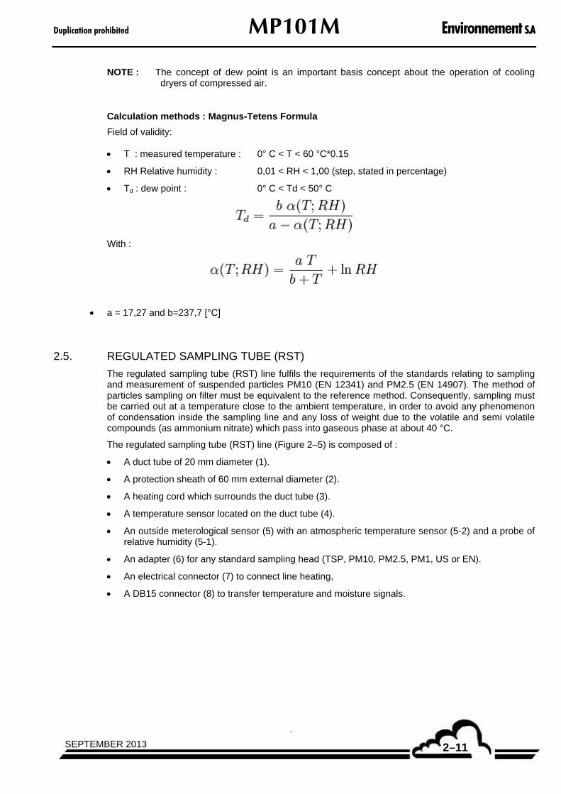
NOTE : The concept of dew point is an important basis concept about the operation of cooling dryers of compressed air.
Calculation methods : Magnus-Tetens Formula
Field of validity:
T : measured temperature : 0° C < T < 60 °C*0.15
RH Relative humidity : 0,01 < RH < 1,00 (step, stated in percentage)
Td : dew point : 0° C < Td < 50° C
With :
a = 17,27 and b=237,7 [°C]
2.5. REGULATED SAMPLING TUBE (RST)
The regulated sampling tube (RST) line fulfils the requirements of the standards relating to sampling and measurement of suspended particles PM10 (EN 12341) and PM2.5 (EN 14907). The method of particles sampling on filter must be equivalent to the reference method. Consequently, sampling must be carried out at a temperature close to the ambient temperature, in order to avoid any phenomenon of condensation inside the sampling line and any loss of weight due to the volatile and semi volatile compounds (as ammonium nitrate) which pass into gaseous phase at about 40 °C.
The regulated sampling tube (RST) line (Figure 2–5) is composed of :
A duct tube of 20 mm diameter (1).
A protection sheath of 60 mm external diameter (2).
A heating cord which surrounds the duct tube (3).
A temperature sensor located on the duct tube (4).
An outside meterological sensor (5) with an atmospheric temperature sensor (5-2) and a probe of relative humidity (5-1).
An adapter (6) for any standard sampling head (TSP, PM10, PM2.5, PM1, US or EN).
An electrical connector (7) to connect line heating,
A DB15 connector (8) to transfer temperature and moisture signals.

Environnement S.A MP101M Duplication prohibited
SEPTEMBER 20132–12
Figure 2–5 – Regulated sampling tube (RST) line assembly

Duplication prohibited MP101M Environnement S.A
2–13SEPTEMBER 2013
The sampling temperature control is managed by the software of the device in the following way:
Sampling is carried out at atmospheric temperature.
A continuous measurement of external relative humidity is carried out,
When the RH value exceeds the empirical threshold of 60%, the line is heated and controlled (with a PID standard integration) at a temperature equal to the atmospheric temperature + 5 °C, in order to avoid condensation inside the line.
T head = T atmospheric + 5 °C.

Environnement S.A MP101M Duplication prohibited
SEPTEMBER 20132–14
This page is intentionally left blank

Duplication prohibited MP101M Environnement S.A
3–1SEPTEMBER 2013
CHAPTER 3
OPERATION
3.1 INITIAL START-UP 3–4
3.1.1 PRELIMINARY OPERATIONS (FIGURE 3–1) 3–4
3.1.2 STARTING UP THE UNIT 3–5
3.2 PROGRAMMING THE MP101M 3–7
3.2.1 SELECTION AND MODIFICATION OF PROGRAMMABLE PARAMETERS 3–7 3.2.1.1 Screen areas definition 3–7 3.2.1.2 Definition of main functions of the keyboard 3–8
3.2.2 PROGRAMMING THE OPERATING PARAMETERS 3–8 3.2.2.1 Programming the numerical parameters 3–8 3.2.2.2 Selection of a parameter in a toggle list 3–8
3.3 DESCRIPTION OF THE DIFFERENT SCREENS 3–10
3.3.1 MAIN MENU 3–10
3.3.2 MEASUREMENT 3–11 3.3.2.1 MEASUREMENT Instantaneous 3–12 3.3.2.2 MEASUREMENT Average 3–13 3.3.2.3 MEASUREMENT Synoptic 3–14 3.3.2.4 MEASUREMENT Graphic 3–16 3.3.2.5 MEASUREMENT Alarm display 3–17 3.3.2.6 MEASUREMENT Current cycle 3–18
3.3.3 CALIBRATION 3–19 3.3.3.1 CALIBRATION Beta gauge 3–20 3.3.3.2 CALIBRATION Linearizations 3–26 3.3.3.3 CALIBRATION Flow rate 3–27 3.3.3.4 CALIBRATION Pressures 3–32
3.3.4 CONFIGURATION 3–33 3.3.4.1 CONFIGURATION Date/Time/Language 3–33 3.3.4.2 CONFIGURATION Measurement mode 3–34 3.3.4.3 CONFIGURATION Measure channels 3–37 3.3.4.4 CONFIGURATION Offsets / Units / Conversions 3–38 3.3.4.5 CONFIGURATION Alarms Control 3–38 3.3.4.6 CONFIGURATION Communications Serial link 3–39 3.3.4.7 CONFIGURATION Communication Network configuration 3–40 3.3.4.8 CONFIGURATION Communication UDP server 3–41 3.3.4.9 CONFIGURATION Factory setting 3–41
3.3.5 STORED DATA 3–42
3.3.6 TESTS 3–45 3.3.6.1 TESTS MUX signals 3–45

Environnement S.A MP101M Duplication prohibited
SEPTEMBER 20133–2
3.3.6.2 TESTS Arm7 inputs - outputs 3–47 3.3.6.3 TESTS Mother board inputs - outputs 3–48 3.3.6.4 TESTS Gauge test 3–52 3.3.6.5 TESTS Mass test 3–55
3.3.7 I2C CARD(S) 3–59 3.3.7.1 I2C CARD(S) Estel card(s) 3–59 3.3.7.2 I2C CARD(S) RST board 3–60 3.3.7.3 I2C CARD(S) CPM board 3–61
3.3.8 USB FLASH DRIVE 3–62 3.3.8.1 USB FLASH DRIVE Flash drive information 3–63 3.3.8.2 USB FLASH DRIVE Backup data 3–64 3.3.8.3 USB FLASH DRIVE Erase flash drive data 3–65 3.3.8.4 USB FLASH DRIVE System restoration 3–65 3.3.8.5 USB FLASH DRIVE Withdraw 3–66
Figure 3–1 – Fluids and electric connection 3–4 Figure 3–2 – Menu and sub-menu tree 3–9 Figure 3–3 – Reference gauge insertion 3–22 Figure 3–4 – Putting in place the reference gauge 3–57 Figure 3–5 – USB disk 3–62
Table 3-1 – DB37 and DB25 connector links 3–3 Table 3-2 – Multiplexer (MUX) signals (Acceptable limits on channel 1 to 16 of the multiplexer) 3–46
Duplication prohibited MP101M Environnement S.A
3–3SEPTEMBER 2013
3 OPERATION
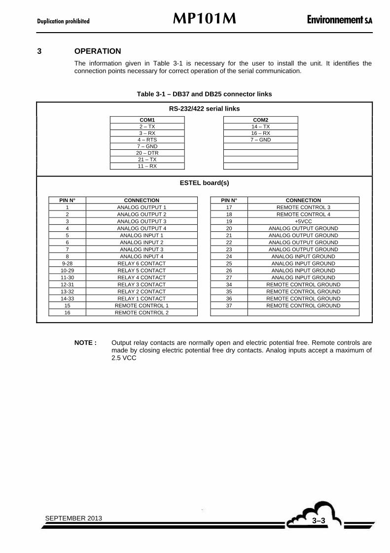
The information given in Table 3-1 is necessary for the user to install the unit. It identifies the connection points necessary for correct operation of the serial communication.
Table 3-1 – DB37 and DB25 connector links
RS-232/422 serial links
COM1
COM2 2 – TX 14 – TX
3 – RX 16 – RX 4 – RTS 7 – GND 7 – GND 20 – DTR 21 – TX
11 – RX
ESTEL board(s)
PIN N° CONNECTION PIN N° CONNECTION
1 ANALOG OUTPUT 1 17 REMOTE CONTROL 3 2 ANALOG OUTPUT 2 18 REMOTE CONTROL 4 3 ANALOG OUTPUT 3 19 +5VCC 4 ANALOG OUTPUT 4 20 ANALOG OUTPUT GROUND 5 ANALOG INPUT 1 21 ANALOG OUTPUT GROUND 6 ANALOG INPUT 2 22 ANALOG OUTPUT GROUND 7 ANALOG INPUT 3 23 ANALOG OUTPUT GROUND 8 ANALOG INPUT 4 24 ANALOG INPUT GROUND
9-28 RELAY 6 CONTACT 25 ANALOG INPUT GROUND 10-29 RELAY 5 CONTACT 26 ANALOG INPUT GROUND 11-30 RELAY 4 CONTACT 27 ANALOG INPUT GROUND 12-31 RELAY 3 CONTACT 34 REMOTE CONTROL GROUND 13-32 RELAY 2 CONTACT 35 REMOTE CONTROL GROUND 14-33 RELAY 1 CONTACT 36 REMOTE CONTROL GROUND
15 REMOTE CONTROL 1 37 REMOTE CONTROL GROUND
16 REMOTE CONTROL 2
NOTE : Output relay contacts are normally open and electric potential free. Remote controls are made by closing electric potential free dry contacts. Analog inputs accept a maximum of 2.5 VCC

Environnement S.A MP101M Duplication prohibited
SEPTEMBER 20133–4
3.1 INITIAL START-UP
The monitor is checked and calibrated in factory before delivery.
3.1.1 PRELIMINARY OPERATIONS (FIGURE 3–1)
Start-up first consists in carrying out the following preliminary operations:
Visually examine the interior of the instrument to ensure that no component has been damaged during transport.
Connect the supply cable of the pump assembly (5).
Connect the pump sampling pipe to the analyzer "pump outlet" (8).
Connect the regulated sampling tube (RST) as indicated in section1.2.4.2 / a.3 of chapter 1, titled as: Installing the regulated sampling tube (RST).
Connect the cord of sampling head heating (3) and the supply cable of the meterological sensors (6).
Connect the electrical (mains) power supply cable (1) to a 230 V - 50 Hz + ground socket or to a 115 V - 60 Hz + ground socket, according to the power supply specified on order.
Connect the digital outlets to the DB25 connector (4).
Connect the TCP/IP socket (7) if needed.
Connect the CPM socket (11) if CPM option available.
(1) general fuse F1 and electrical (mains) power supply block, (3) TUCHEL connector for heating of sampling head inlet, (4) RS232/RS422 socket, (5) power supply of external pump, (6) head sensors, (7) TCP/IP socket, (8) pump outlet, (11) connection socket with the CPM option.
Figure 3–1 – Fluids and electric connection

Duplication prohibited MP101M Environnement S.A
3–5SEPTEMBER 2013
3.1.2 STARTING UP THE UNIT
Carry out, in the following order, the INSTALLATION / STARTING UP procedure described below :
1/ Press down the ON/OFF push-button located on the front panel to start the unit. The synoptic screen is displayed and the instrument passes into the "WARM-UP" cycle. During the warm-up cycle, the instrument self-checks its various parameters. The "WARM UP" message blinks at the top of the right corner of the Synoptic screen.
When all the operation parameters (pressure, temperature, voltage) are within operational limits, the "WARM-UP" cycle is terminated.
STOP
After a specified period of time without any keyboard action (duration is programmable in the «Configuration Measurement mode» menu), the screen enters stand-by mode. Pressing any key makes the screen return to display mode.
2/ Carry out Beta gauge calibration (« CALIBRATION Beta gauge » menu).
NOTE : Calibration lasts for about 1h (for 10 cycles). Refer to section 3.3.3.1 for procedure details.
3/ Check pressure sensors calibration (« CALIBRATION Pressures » menu) :
Using a reference barometer, check values of upstream pressure, downstream pressure and atmospheric pressure. They must all be equal to the atmospheric pressure read on the barometer (pump being switched off).
Refer to section 3.3.3.4 for procedure details.
4/ Check calibration of temperature and relative humidity sensors :
In the « I2C Card(s) RST board » menu, check the values of Atmos. temperature and Relative humidity using the reference sensors.
Environnement S.A MP101M Duplication prohibited
SEPTEMBER 20133–6
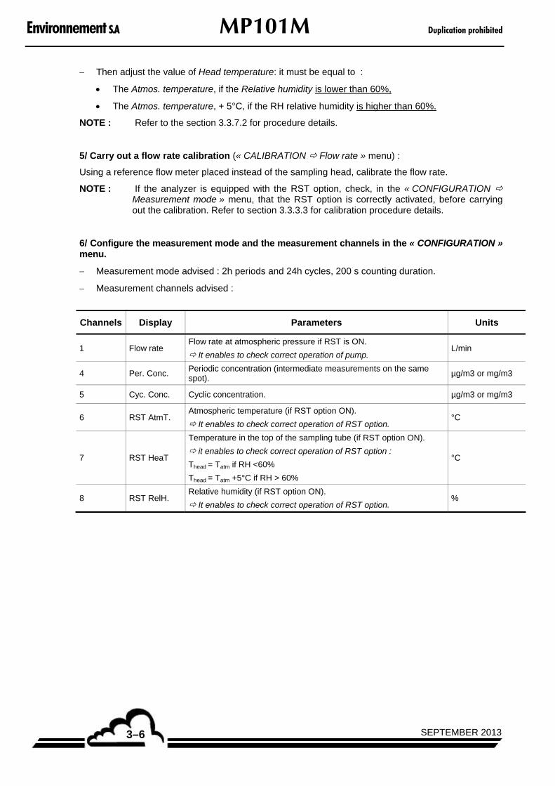
Then adjust the value of Head temperature: it must be equal to :
The Atmos. temperature, if the Relative humidity is lower than 60%,
The Atmos. temperature, + 5°C, if the RH relative humidity is higher than 60%.
NOTE : Refer to the section 3.3.7.2 for procedure details.
5/ Carry out a flow rate calibration (« CALIBRATION Flow rate » menu) :
Using a reference flow meter placed instead of the sampling head, calibrate the flow rate.
NOTE : If the analyzer is equipped with the RST option, check, in the « CONFIGURATION Measurement mode » menu, that the RST option is correctly activated, before carrying out the calibration. Refer to section 3.3.3.3 for calibration procedure details.
6/ Configure the measurement mode and the measurement channels in the « CONFIGURATION » menu.
Measurement mode advised : 2h periods and 24h cycles, 200 s counting duration.
Measurement channels advised :
Channels Display Parameters Units
1 Flow rate Flow rate at atmospheric pressure if RST is ON.
It enables to check correct operation of pump. L/min
4 Per. Conc. Periodic concentration (intermediate measurements on the same spot).
µg/m3 or mg/m3
5 Cyc. Conc. Cyclic concentration. µg/m3 or mg/m3
6 RST AtmT. Atmospheric temperature (if RST option ON).
It enables to check correct operation of RST option. °C
7 RST HeaT
Temperature in the top of the sampling tube (if RST option ON).
it enables to check correct operation of RST option :
Thead = Tatm if RH <60%
Thead = Tatm +5°C if RH > 60%
°C
8 RST RelH. Relative humidity (if RST option ON).
It enables to check correct operation of RST option. %

Duplication prohibited MP101M Environnement S.A
3–7SEPTEMBER 2013
3.2 PROGRAMMING THE MP101M
3.2.1 SELECTION AND MODIFICATION OF PROGRAMMABLE PARAMETERS
The keyboard is located under the LCD screen. The bottom line gives the function of each key for the current screen.
The title of the menus and the selected fields are displayed in reverse video. By default, the first line of the menus is selected. In the next sections, the selected parameters are symbolized in white on black background.
3.2.1.1 Screen areas definition
Information area: it displays the date and time in the top left corner. In the top right corner, the "ALARM" message is displayed if a fault concerning the operating parameters of the analyzer is detected.
Measurement or configuration area: it displays the measurement parameters (parameters, value, units ...) or the configurable parameters according to the selected menu.
Status area and key functions: it displays the keys function, the operating mode of the analyzer.
NOTE : In the next sections, the keys are symbolized by the icon or the function displayed inside brackets.

Environnement S.A MP101M Duplication prohibited
SEPTEMBER 20133–8
3.2.1.2 Definition of main functions of the keyboard
The availability of these functions is context dependent.
[] Used to display the previous menu or to abort the current operation (parameter programming, etc.)
[] Used to select the required sub-menu and the parameter to be modified. It is also used to increase the digit whose modification is in progress.
[] Used to select the sub-menu and the parameter to be modified. It is also used to decrease the digit whose modification is in progress.
[] Moves the cursor to the left (only available during numerical parameters modifications).
[] Moves the cursor to the right (only available during numerical parameters modifications).
[] Used to modify selected parameters.
[ ] Used to validate the selection or the digit whose modification is in progress.
[>] and [>>]
Used to display the next page. When there are several parameters, pressing down [>>] allows displaying the next parameters.
3.2.2 PROGRAMMING THE OPERATING PARAMETERS
3.2.2.1 Programming the numerical parameters
Select the parameter with the [] or [] key in the appropriate menu, press down the [] key to access to the modification of the parameter, the 1st digit blinks. Select the digit to be modified with the
[] or [] key then increase it with the [] key or decrease it with the [] key. The [ ] key validates the modifications of the selected field, the [] key cancels the modifications of the selected field.
3.2.2.2 Selection of a parameter in a toggle list
Select the parameter with the [] or [] key in the appropriate menu, press down the [] key to access to the modification of the parameter, the field blinks. Select with the [] or [] key the wanted
value in the toggle list. The [ ] key validates the modifications of the selected field, the [] key cancels the modifications of the selected field.

Duplication prohibited MP101M Environnement S.A
3–9SEPTEMBER 2013
The diagram of menu and sub-menu tree of the software is given in the Figure 3–2.
MAIN MENU
MEASUREMENT CALIBRATION CONFIGURATION STORED DATA TESTS
Instantaneous
Average
Synoptic
Alarm display
Beta gauge
Linearizations
Date/time/Language
Measurementmode
Offsets/Units/Conversions
Communications
Factory settings
Tabular
Histogram
RESET
MUX signals
Gauge test
ARM7 Inputs/Outputs
Mother boardInput/output
Measurechannels
Graphic
Current cycle
Serial link
UDP server
Networkconfiguration
Mass test
I2C CARD(S)
ESTEL card(s)
RST board
CPM board
Alarms control
Pressures
Flow rate
Figure 3–2 – Menu and sub-menu tree
Environnement S.A MP101M Duplication prohibited
SEPTEMBER 20133–10
3.3 DESCRIPTION OF THE DIFFERENT SCREENS
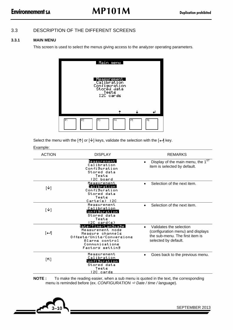
3.3.1 MAIN MENU
This screen is used to select the menus giving access to the analyzer operating parameters.
Select the menu with the [] or [] keys, validate the selection with the [ ] key.
Example:
ACTION DISPLAY REMARKS
Measurement
Calibration
Configuration
Stored data
Tests
I2C board
Display of the main menu, the 1ST item is selected by default.
[] Measurement
Calibration
Configuration
Stored data
Tests
Carte(s) I2C
Selection of the next item.
[] Measurement
Calibration
Configuration
Stored data
Tests
I2C card(s)
Selection of the next item.
[ ] Date/Time/Language
Measurement mode
Measure channels
Of fsets/Units/Conversions
Alarms control
Communications
Factory setting
Validates the selection (configuration menu) and displays the sub-menu. The first item is selected by default.
[] Measurement
Calibration
Configuration
Stored data
Tests
I2C cards
Goes back to the previous menu.
NOTE : To make the reading easier, when a sub menu is quoted in the text, the corresponding menu is reminded before (ex. CONFIGURATION Date / time / language).

Duplication prohibited MP101M Environnement S.A
3–11SEPTEMBER 2013
3.3.2 MEASUREMENT
This screen enables the user to select the measurement display mode: instantaneous, average, synoptic or graphic, to display the alarms and to check the status of the current cycle.
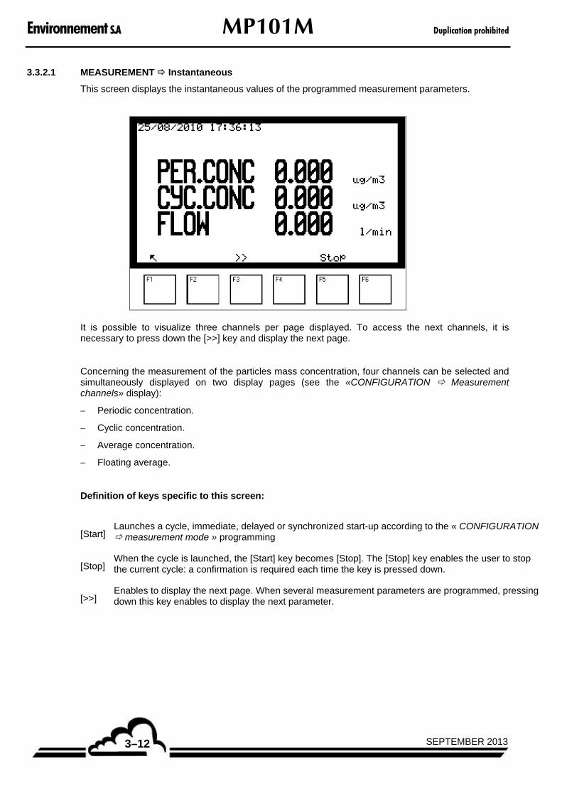
Environnement S.A MP101M Duplication prohibited
SEPTEMBER 20133–12
3.3.2.1 MEASUREMENT Instantaneous
This screen displays the instantaneous values of the programmed measurement parameters.
It is possible to visualize three channels per page displayed. To access the next channels, it is necessary to press down the [>>] key and display the next page.
Concerning the measurement of the particles mass concentration, four channels can be selected and simultaneously displayed on two display pages (see the «CONFIGURATION Measurement channels» display):
Periodic concentration.
Cyclic concentration.
Average concentration.
Floating average.
Definition of keys specific to this screen:
[Start] Launches a cycle, immediate, delayed or synchronized start-up according to the « CONFIGURATION measurement mode » programming
[Stop] When the cycle is launched, the [Start] key becomes [Stop]. The [Stop] key enables the user to stop the current cycle: a confirmation is required each time the key is pressed down.
[>>] Enables to display the next page. When several measurement parameters are programmed, pressing down this key enables to display the next parameter.

Duplication prohibited MP101M Environnement S.A
3–13SEPTEMBER 2013
3.3.2.2 MEASUREMENT Average
This screen displays the averages of the instantaneous values of the programmed measurement parameters.
Definition of keys specific to this screen:
For this screen, the [Start], [Stop] and [>>] keys have the same functions as for the «MEASUREMENT instantaneous» screen.
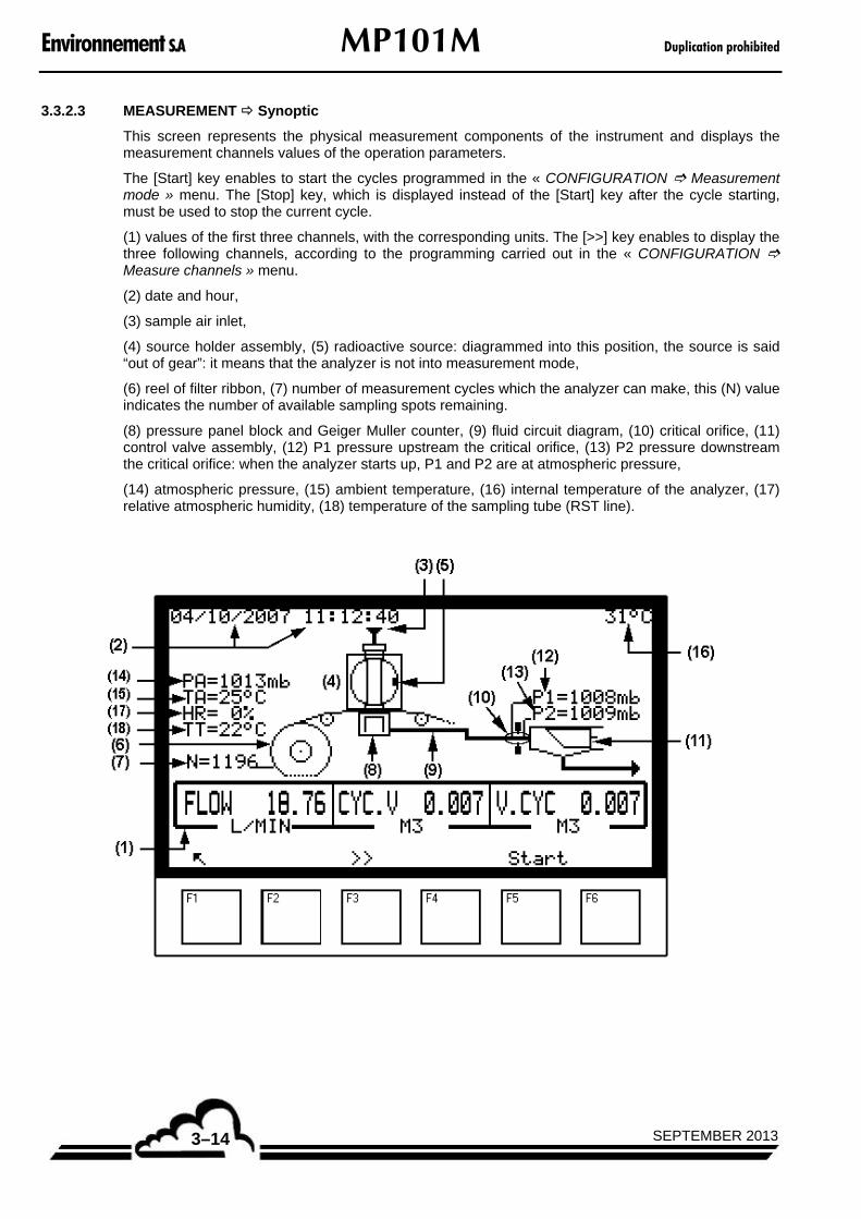
Environnement S.A MP101M Duplication prohibited
SEPTEMBER 20133–14
3.3.2.3 MEASUREMENT Synoptic
This screen represents the physical measurement components of the instrument and displays the measurement channels values of the operation parameters.
The [Start] key enables to start the cycles programmed in the « CONFIGURATION Measurement mode » menu. The [Stop] key, which is displayed instead of the [Start] key after the cycle starting, must be used to stop the current cycle.
(1) values of the first three channels, with the corresponding units. The [>>] key enables to display the three following channels, according to the programming carried out in the « CONFIGURATION Measure channels » menu.
(2) date and hour,
(3) sample air inlet,
(4) source holder assembly, (5) radioactive source: diagrammed into this position, the source is said “out of gear”: it means that the analyzer is not into measurement mode,
(6) reel of filter ribbon, (7) number of measurement cycles which the analyzer can make, this (N) value indicates the number of available sampling spots remaining.
(8) pressure panel block and Geiger Muller counter, (9) fluid circuit diagram, (10) critical orifice, (11) control valve assembly, (12) P1 pressure upstream the critical orifice, (13) P2 pressure downstream the critical orifice: when the analyzer starts up, P1 and P2 are at atmospheric pressure,
(14) atmospheric pressure, (15) ambient temperature, (16) internal temperature of the analyzer, (17) relative atmospheric humidity, (18) temperature of the sampling tube (RST line).

Duplication prohibited MP101M Environnement S.A
3–15SEPTEMBER 2013
Description of the sequence chain when the system starts up ([Start] key):
1 – the pressure panel goes down.
2 – the filter paper is fed for a distance equivalent to one step, and is put in place under the filter-holder.
3 – the source holder cylinder is placed in « sampling » position.
4 – the pressure panel is placed in high position, under the filter, in order to guarantee the tightness between the pressure panel and the sampling conduit.
5 – the pump starts into « Drying paper » mode: this mode is programmed for 2 mn duration (see diagram 1 below).
6 – the Geiger Muller counter passes into pre-heating: the « Geiger pre-heating » message is displayed (see diagram 2 below).
7 – the pump stops.
8 – the source-holder cylinder gets into the « Measurement » position: the « Blank counting » message is displayed (see diagram 3 below), it means that the blank is being counted. The other measurement messages displayed are the following: the time countdown for the current blank, the supply voltage of the Geiger counter, the counting stated in count per seconds (cp/s).
9 – at the end of the « Blank counting », the source holder cylinder is placed again into sampling.
10 – the pump starts, and the « Sampling…» message is displayed (see diagram 4 below). The instrument takes the sample during the programmed duration, at the setting flow rate of 1 m3/h.
11 – the pump stops, sampling is finished.
12 – the instrument launches the Geiger counter pre-heating, then the source-holder cylinder is placed into « Measurement » position and carries out the measurement of the radiation attenuation on the particles deposit at the filter surface.
At any time, the user can interrupt the sampling and the current measurement by pressing down the [Stop] key: the instrument asks for confirmation, YES or NO. Validate the wanted choice.
(1) (2)
(3) (4)
Definition of keys specific to this screen:
[Start], [Stop] and [>>] have the same functions as for the « MEASUREMENT Instantaneous » display. In case of delayed start, once the [Start] key is pressed, the device waits for the programmed hour. In case of synchronized start, the analyzer waits for an external dry contact to be closed.

Environnement S.A MP101M Duplication prohibited
SEPTEMBER 20133–16
3.3.2.4 MEASUREMENT Graphic
This screen is used to adjust the parameter for graphic plot of measurement channel values: it enables the user to define:
The measurement channel to display.
The max. and min. display scales.
The speed of graphic plot.
The [>>] key enables the user to access the graphs.
The validation to « ON » of the measurement channel field causes the plot display of the corresponding measurement values, according to the parameters previously defined in the screen shown below.
This screen is used for graphic plot of measurement values. The vertical line indicates the position of the current measurement: the refreshed measurements are given on the left side of this line.
The [Reset] key resets the graphic plot to zero, the [<<] enables the user to return to the previous screen, the [] enables the user to quit the « MEASUREMENT Graphic » sub-menu.
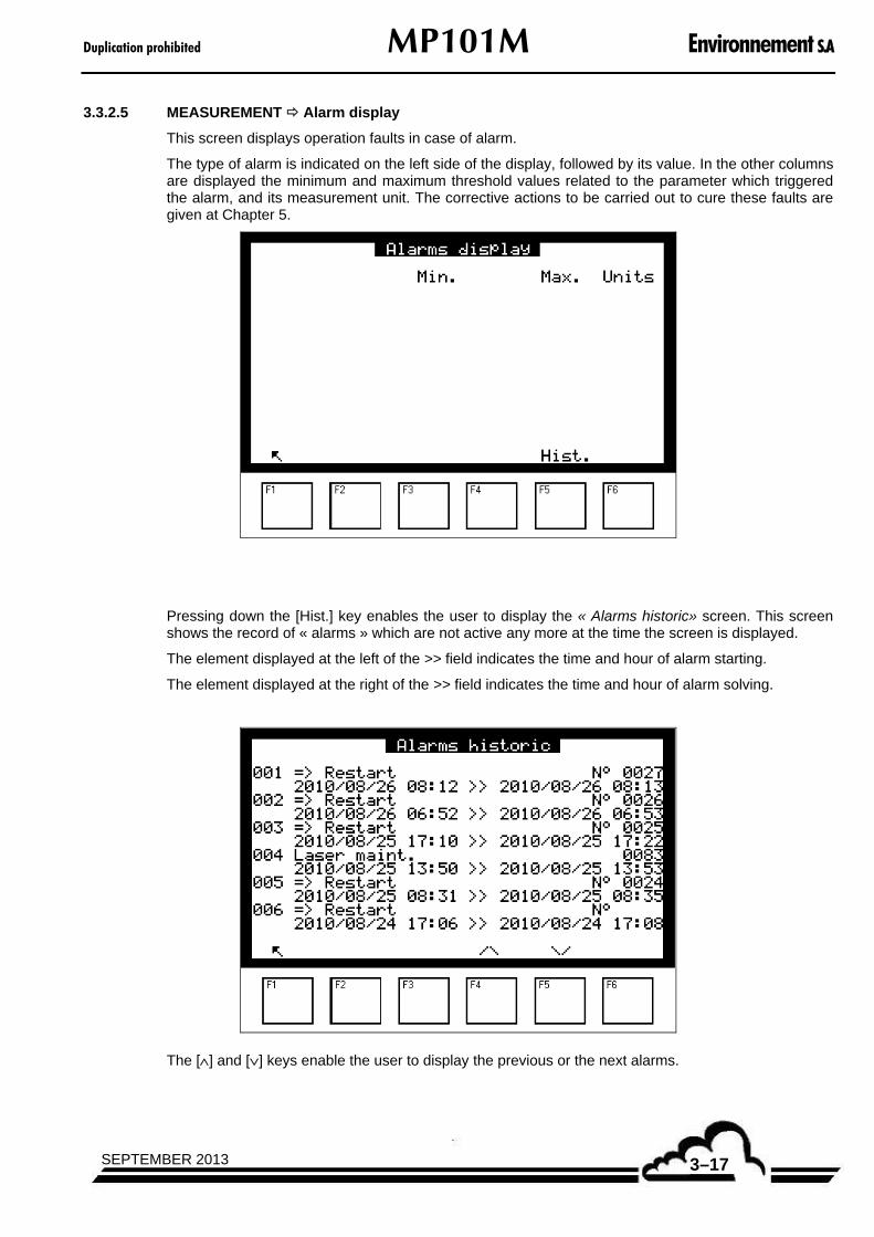
Duplication prohibited MP101M Environnement S.A
3–17SEPTEMBER 2013
3.3.2.5 MEASUREMENT Alarm display
This screen displays operation faults in case of alarm.
The type of alarm is indicated on the left side of the display, followed by its value. In the other columns are displayed the minimum and maximum threshold values related to the parameter which triggered the alarm, and its measurement unit. The corrective actions to be carried out to cure these faults are given at Chapter 5.
Pressing down the [Hist.] key enables the user to display the « Alarms historic» screen. This screen shows the record of « alarms » which are not active any more at the time the screen is displayed.
The element displayed at the left of the >> field indicates the time and hour of alarm starting.
The element displayed at the right of the >> field indicates the time and hour of alarm solving.
The [] and [] keys enable the user to display the previous or the next alarms.

Environnement S.A MP101M Duplication prohibited
SEPTEMBER 20133–18
3.3.2.6 MEASUREMENT Current cycle
This screen is used to visualize the status of the current cycle and period as well as the date and time to start the next cycle.
Date and time field indicates the present date and hour.
General start field indicates the date and hour of the first cycle starting for the current sequence.
Cycles field : the number on the right side indicates the current cycle number with regard to the general start.
Start field indicates the date and hour of the current cycle starting.
End field indicates the date and hour of the pump stop and the current cycle end.
Period field : the number on the right side indicates the current period number with regard to the cycle start.
Start field indicates the date and hour of the current period starting.
Start flow field indicates the date and hour of the pump start for the current period.
HV Geiger ON field indicates the date and hour of the counting start (GM counter powered on) for the current period.
End flow field indicates the date and hour of the pump stop for the current period.
End field indicates the date and hour of the current period end and the display of the new concentration values.
Next cycle field indicates the date and hour of the next cycle starting.
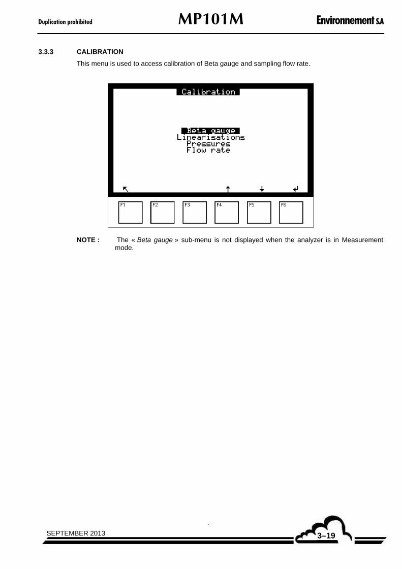
Duplication prohibited MP101M Environnement S.A
3–19SEPTEMBER 2013
3.3.3 CALIBRATION
This menu is used to access calibration of Beta gauge and sampling flow rate.
NOTE : The « Beta gauge » sub-menu is not displayed when the analyzer is in Measurement mode.

Environnement S.A MP101M Duplication prohibited
SEPTEMBER 20133–20
3.3.3.1 CALIBRATION Beta gauge
The screen shown below displays:
the Beta calibration coefficient (K) determined during the previous calibration,
the value of the reference gauge used for the calibration,
the number of consecutive calibrations necessary to obtain a calibration value,
the date of the previous calibration.
In this screen, it is possible to manually modify the K calibration coefficient (for example, after a calibration or a manual check): using the [] and [] keys, select the value of the K coefficient, then press down the [] key and modify the coefficient value with the [] [] [] [] keys. Then validate
with [ ]
By pressing down the [»] key, the user has access to the display which allows calibration of the Beta gauge.
It is necessary to press down the [Auto] key in the screen shown above to access the calibration.

Duplication prohibited MP101M Environnement S.A
3–21SEPTEMBER 2013
Press down the [Start] key to launch the calibration.
This screen is used to monitor the phases sequence using the « > » cursor.
The instrument enters into the « Initialization » phase, the filter paper is fed for one step, and the pressure plate is placed into high position, against the filter paper. Then, the pump starts: the device passes into the « Drying paper » phase with visualization of the drying time countdown.
Then the instrument passes into « Blank » mode and displays the countdown of pre-heating time of the GM counter, and the measurement of blank counting. The left side value gives the instantaneous counting value, the right side value gives the average value of the previous counting.

Environnement S.A MP101M Duplication prohibited
SEPTEMBER 20133–22
The « 1/10 » ratio indicates that the instrument carries out the first blank of a 10 calibrations series. The instrument will repeat 10 times the blank measurement, as programmed in the Calibration number field.
Between each « Blank », the GM counter is switched off.
When the 10 blanks are finished, the screen displayed the average of the N blank measurements. Then the cursor is placed in front of « Insert reference gauge » and this message blinks.
The user must insert and click-in the reference gauge, guided by the two pins as shown in Figure 3–3.
Figure 3–3 – Reference gauge insertion
Then, press down the [] key.

Duplication prohibited MP101M Environnement S.A
3–23SEPTEMBER 2013
The instrument checks the reference gauge, then the cursor moves to « Calibration » and the instrument starts the calibration. In the next field, the instantaneous value of counting is displayed on the left, and the average value of counting is displayed on the right.
When the programmed measurements of calibration are finished, the analyzer asks to remove the reference gauge : the cursor moves to the Pull out reference gauge field which blinks. The new calibration K factor is displayed. The user pulls out the reference gauge and validates by pressing down the [F3] key.
Ending of Beta gauge calibration: the instrument replaces the pressure plate against the filter in order to restart the measurements or to carry out a new calibration.
Then, the user can display the calibration report of the Beta gauge. To do that, press down the [>>] key of the screen shown above to return to the screen giving the date of the previous calibration.
In this screen, press down the [>>] key, then the [Report] key in order to display the screen shown below:

Environnement S.A MP101M Duplication prohibited
SEPTEMBER 20133–24
It gives the summary of the last calibration with :
The number of calibration cycles performed, the counting duration for each cycle, the value of the reference gauge, stated into µg/cm2.
The average values of blanks and calibrations with the average of their respective measurement temperatures.
The « K final » or final span factor obtained at the end of the calibration and stored into memory.
In this screen, pressing down the [Blanks] key enables the user to display the screen shown below:
This screen displays:
The detail of blank measurements with the value of filter temperature when the blank measurement is performed,
The average values of blanks and temperature, as displayed in the previous screen.

Duplication prohibited MP101M Environnement S.A
3–25SEPTEMBER 2013
Press down the [<<<] key to return to the previous screen, and press down the [Spans] key to display the screen shown below:
This screen displays :
The detail of measurements carried out on the reference gauge with the value of filter temperature for each measurement,
The average values of reference gauge counting and temperature, as displayed in the screen shown above, Calibrations field.
It is impossible to carry out the Beta gauge calibration when the analyzer is carrying out measurements.
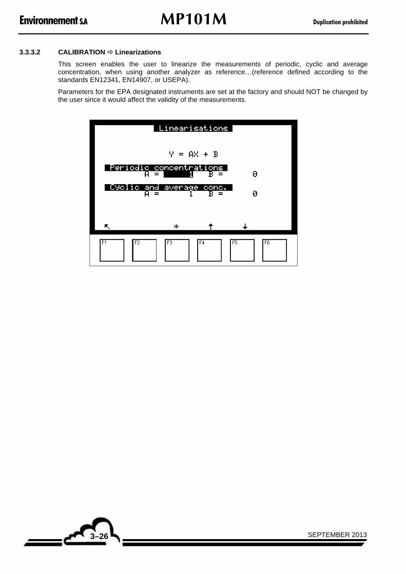
Environnement S.A MP101M Duplication prohibited
SEPTEMBER 20133–26
3.3.3.2 CALIBRATION Linearizations
This screen enables the user to linearize the measurements of periodic, cyclic and average concentration, when using another analyzer as reference…(reference defined according to the standards EN12341, EN14907, or USEPA).
Parameters for the EPA designated instruments are set at the factory and should NOT be changed by the user since it would affect the validity of the measurements.
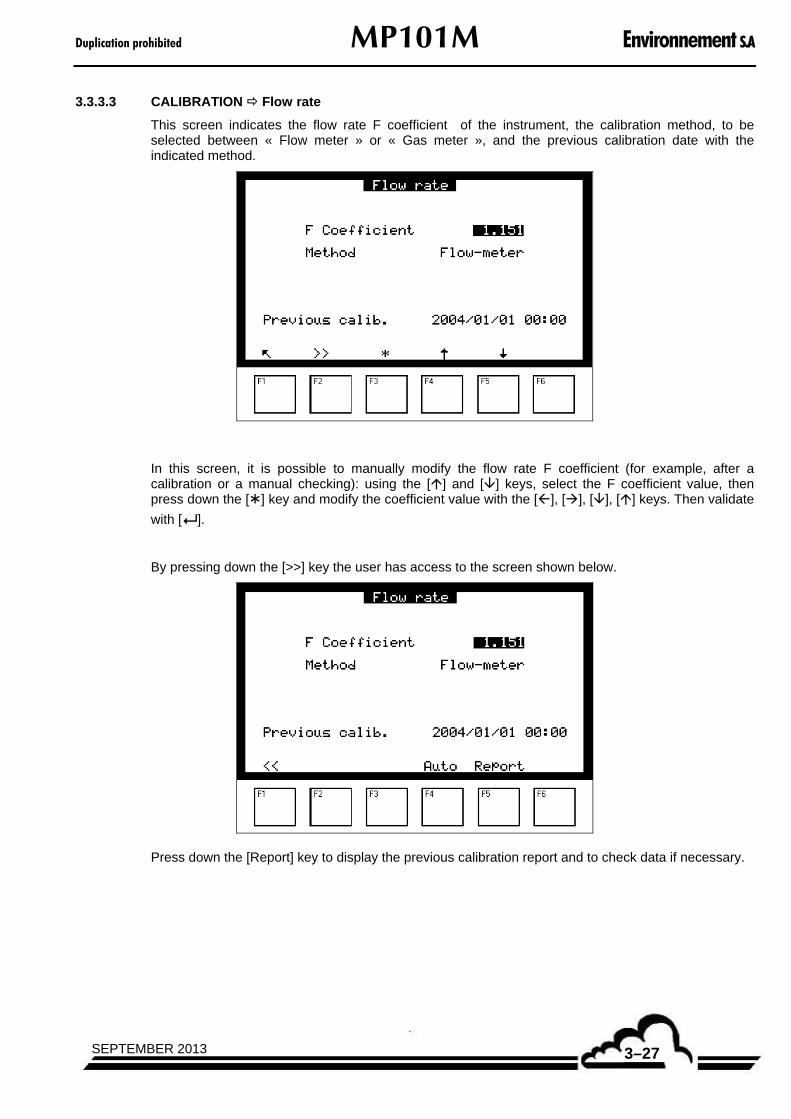
Duplication prohibited MP101M Environnement S.A
3–27SEPTEMBER 2013
3.3.3.3 CALIBRATION Flow rate
This screen indicates the flow rate F coefficient of the instrument, the calibration method, to be selected between « Flow meter » or « Gas meter », and the previous calibration date with the indicated method.
In this screen, it is possible to manually modify the flow rate F coefficient (for example, after a calibration or a manual checking): using the [] and [] keys, select the F coefficient value, then press down the [] key and modify the coefficient value with the [], [], [], [] keys. Then validate
with [ ].
By pressing down the [>>] key the user has access to the screen shown below.
Press down the [Report] key to display the previous calibration report and to check data if necessary.

Environnement S.A MP101M Duplication prohibited
SEPTEMBER 20133–28
This screen displays date and hour of the last calibration, the pressure and temperature values to which flow-rate was calibrated, and flow-rate parameters with the calculated values of the new F coefficient.
Pressures fields :
P1 field : pressure value upstream the critical orifice,
P2 field: pressure value downstream the critical orifice,
Atm. field : atmospheric pressure measurement.
The atmospheric pressure measurement is performed continuously.
Temperatures fields :
Filter field : temperature at level filter,
Atm. field : External temperature measured by the meteo sensor (if the meteo sensor option is available).
Flow-rate fields:
Reference field : the setting value of flow is set to 1 m3/h, it does not vary.
Previous F coef. field : the value of the previous factor is used to calculate the new factor.
Span field : reference flow
New F coef. field : obtained by calculation : )(
)()(measured
previousnew Flow
SpanKK
To carry out calibration, press down the [>>] key to return to the previous screen, and the [Auto] key to launch the automatic calibration of flow rate. The « Calibration cycle » screen shown below is displayed.
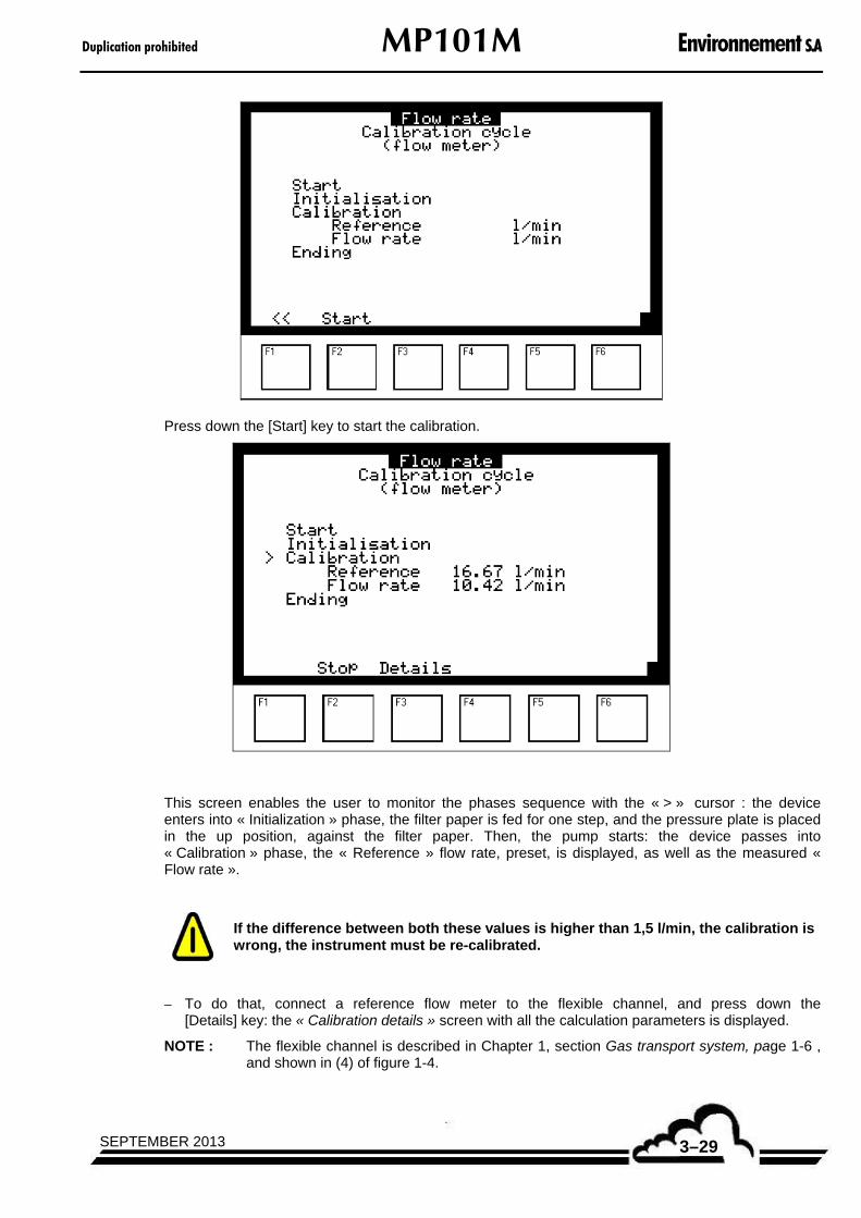
Duplication prohibited MP101M Environnement S.A
3–29SEPTEMBER 2013
Press down the [Start] key to start the calibration.
This screen enables the user to monitor the phases sequence with the « > » cursor : the device enters into « Initialization » phase, the filter paper is fed for one step, and the pressure plate is placed in the up position, against the filter paper. Then, the pump starts: the device passes into « Calibration » phase, the « Reference » flow rate, preset, is displayed, as well as the measured « Flow rate ».
If the difference between both these values is higher than 1,5 l/min, the calibration is wrong, the instrument must be re-calibrated.
– To do that, connect a reference flow meter to the flexible channel, and press down the [Details] key: the « Calibration details » screen with all the calculation parameters is displayed.
NOTE : The flexible channel is described in Chapter 1, section Gas transport system, page 1-6 , and shown in (4) of figure 1-4.

Environnement S.A MP101M Duplication prohibited
SEPTEMBER 20133–30
Pressure fields :
P1 field: pressure value upstream the critical orifice,
P2 field: pressure value downstream the critical orifice,
Atm. field: atmospheric pressure.
Temperature fields :
Filter field : temperature at filter level,
Atm. field: external temperature measured by the meteo sensor (if the meteo sensor option is available).
Flow-rate fields: flow-rate parameters for the current measurement.
Automatic calculation of the flow rate coefficient :
Procedure: it consists in inputting the flow rate values given by the reference flow meter
connected to the analyzer, then to validate this value with the [ ] key. The instrument automatically modifies the flow rate F coefficient, and displays the new flow rate value measured by the analyzer, which is obtained with the new coefficient.
Operating mode :
Using the [] key, go to « Calibration » line, then press down the [] key to activate the input field of the flow rate value read on the reference flow meter connected to the instrument.
Using the [], [] and [] keys, input the flow rate value, stated in l/min, read on the flow
meter. Validate the input with the F6 [ ] key.
Then, the instrument calculates the flow rate span coefficient. : and « F Coef. » is displayed in the corresponding field.
Validate the calculated coefficient by pressing down the [Memo] key the new F Coef. is memorized, its value is updated, and the flow rate measurement is adjusted to the reference value.

Duplication prohibited MP101M Environnement S.A
3–31SEPTEMBER 2013
If the span flow rate does not correspond to the flow rate measured by the instrument (difference > 1,5 l/min), repeat the calibration procedure.
Quit the display by pressing down the [] key, then the [Stop] key.
REMARK : The flow value read on the reference flowmeter is valid for a defined reference temperature Tref and a reference pressure Pref = 1013 hPa.
Thus, it is necessary to convert this flow for the conditions Tatm and Patm in order to compare it with the flow indicated by the analyzer.
atmref
refatmrefatm PT
PTQQ
)(
)()()
Manual adjustment of the motor-driven valve :
From the « Calibration details » screen of the « Flow rate » sub-menu, it is possible to manually control the opening and closing of the motor-driven valve in order to calibrate the flow rate faster.
Press down the [Manu] key : the [--], [-], [0], [+] and [++] keys are displayed (screen shown below).
Connect the flow meter to the flexible channel.
NOTE : The flexible channel is described in Chapter 1, section Gas transport system, page 1-6 , and shown in (4) of figure 1-4.
If the flow rate read on the flow meter is higher than the reference flow rate, press down the [-] or [--] (faster) key.
If the flow rate read on the flow meter is lower than the reference flow rate, press down the [+] or [++](faster) key.
As soon as the flow rate read on the flow meter corresponds to the reference flow rate, press down the [0] key the motor driven valve stops.
NOTE : The flow rate calibration can be carried out in measurement mode : the new calibration coefficient « F Coef. » is immediately taken into account when the [Memo] key is pressed down.

Environnement S.A MP101M Duplication prohibited
SEPTEMBER 20133–32
3.3.3.4 CALIBRATION Pressures
This screen enables the user to calibrate the values of the three pressure sensors :
Upstream pressure,
Downstream pressure,
Atmospheric pressure.
Using a reference sensor (barometric), adjust the A and B values for the three sensors using the [], [], [] keys.
The pump can be activated by pressing down the [Pump ON] key.
NOTE : It is possible to carry out this calibration when the analyzer is in measurement mode

Duplication prohibited MP101M Environnement S.A
3–33SEPTEMBER 2013
3.3.4 CONFIGURATION
This menu gives access to the following functions:
Response time programming.
Analog output configuration.
Unit modification and offset adjustment.
Alarm thresholds programming, and activation and assignment of alarm relays.
Serial link programming.
Reset of main programmable parameters.
3.3.4.1 CONFIGURATION Date/Time/Language
This screen is used to set the internal clock of the analyzer, as well as to choose the displayed language from French, English, German, Italian and Spanish.
The Working time field indicates the number of days while the analyzer worked since the last software updating.
The Software version field gives the software version number to be reminded in case of dysfunction.

Environnement S.A MP101M Duplication prohibited
SEPTEMBER 20133–34
3.3.4.2 CONFIGURATION Measurement mode
This screen allows the user to program:
The sampling cycle duration, configurable from 1h to 96 hours : the standard value is 24 hours.
The measurement period during each cycle, configurable from 10 minutes to 48 hours : the US EPA standard value is 1 hour.
The sampling flow rate of the sampled air, adjustable from 0,5 to 1,5 m3/h: the standard value is 1 m3/h , i.e. 16,67 l/mn.
The counting time, i.e. the duration of the radiation counting. It is recommended to have a minimum counting time of 120 seconds.
The running average, with 2 configurable parameters:
The integration duration, i.e. the time interval within the measurement averages will be carried out, subdivided into calculation steps.
Calculation step: time interval defined for one measurement.
The [>] key enables the user to display the next screen:
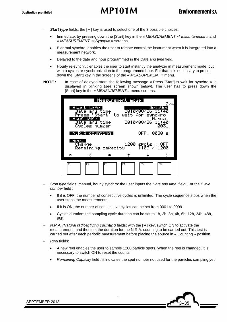
Duplication prohibited MP101M Environnement S.A
3–35SEPTEMBER 2013
Start type fields: the [] key is used to select one of the 3 possible choices:
Immediate: by pressing down the [Start] key in the « MEASUREMENT Instantaneous » and « MEASUREMENT Synoptic » screens,
External synchro: enables the user to remote control the instrument when it is integrated into a measurement network.
Delayed to the date and hour programmed in the Date and time field,
Hourly re-synchr. : enables the user to start instantly the analyzer in measurement mode, but with a cycles re-synchronization to the programmed hour. For that, it is necessary to press down the [Start] key in the screens of the « MEASUREMENT » menu.
NOTE : In case of delayed start, the following message « Press [Start] to wait for synchro » is displayed in blinking (see screen shown below). The user has to press down the [Start] key in the « MEASUREMENT » menu screens.
Stop type fields: manual, hourly synchro: the user inputs the Date and time field. For the Cycle number field :
If it is OFF, the number of consecutive cycles is unlimited. The cycle sequence stops when the user stops the measurements,
If it is ON, the number of consecutive cycles can be set from 0001 to 9999.
Cycles duration: the sampling cycle duration can be set to 1h, 2h, 3h, 4h, 6h, 12h, 24h, 48h, 96h.
N.R.A. (Natural radioactivity) counting fields: with the [] key, switch ON to activate the measurement, and then set the duration for the N.R.A. counting to be carried out. This test is carried out after each periodic measurement before placing the source in « Counting » position.
Reel fields:
A new reel enables the user to sample 1200 particle spots. When the reel is changed, it is necessary to switch ON to reset the counts.
Remaining Capacity field : it indicates the spot number not used for the particles sampling yet.

Environnement S.A MP101M Duplication prohibited
SEPTEMBER 20133–36
Press down the [>] key to display the next screen.
Contamination test field : if this field is activated (ON position), the analyzer will check the radioactive contamination at the end of each measurement cycle. This checking will be carried out with the Geiger counter, without using the radioactive source. An alarm is activated if the count exceeds 30 counts/s when the source is in sampling position. Therefore, it is necessary to go to one of the « Instantaneous », « Average », « Synoptic » screens of the « MEASUREMENT » menu to activate the measurement mode by pressing down the [Start] key.
Geiger field informs about the number of counts received by the detector since its installation. Its average life time is 5 x 10¹⁰ counts.
RST option field : allows activating the RST option.
CPM option field : refer to the technical manual of CPM.
Press down the [>] key to display the next screen :
DAC memo. field: when this field is ON, the analog outputs are stopped to the last measurement values during the following cycles.

Duplication prohibited MP101M Environnement S.A
3–37SEPTEMBER 2013
Maintenance field: when this field is ON, it enables the user to trigger one of the alarm relays.
Light screen Off delay field allows the user to program the time delay after which, without any action on keyboard, the screen passes to stand-by mode.
Starting screen field enables the user to select the screen to be displayed after warm-up, when the device is started-up. Four screen selections are possible: « Instantaneous », « Synoptic », « Average », « Graphic », of the « MEASUREMENT » menu.
3.3.4.3 CONFIGURATION Measure channels This screen is used to select the parameter, and the display format for each measure channel.
Channels number field allows the user to program the number of processed channels (maximum 32). When more than eight parameters are programmed, the [>>] and [<<]
keys enable the user to
go from the 1 to 8 parameters page to the 9 to 16 parameters page.
Formats fields are used to choose the display format from 4 possibilities (X.XXX, XX.XX, XXXX.X, XXXX). The "Auto" format manages the comma place in order to display the best resolution at any time.
Units fields refer to the units programmed in the «CONFIGURATION Offsets and units» screen.
It is possible to modify the measurement channels order by selecting the channel name, then using the [], [], [] keys then the F6 key.
Once placed on the channel name, it is possible to suppress this channel (press down the [F6] key, then the [Sup] key), and/or insert a new one (press down the [F6] key, then the [Ins.] key).

Environnement S.A MP101M Duplication prohibited
SEPTEMBER 20133–38
3.3.4.4 CONFIGURATION Offsets / Units / Conversions
This screen is used to program the offset on the eight channels available in this screen : this value is added to the measurements value.
It is also used to program the measurement unit, as for the conversion coefficients:
3.3.4.5 CONFIGURATION Alarms Control
Two thresholds per parameter are programmable: Threshold 1 and Threshold 2, they enable the user to activate the relays and the alarm messages. When the Alarms display field is OFF, the alarm relays are inhibited and their alarm is not displayed.
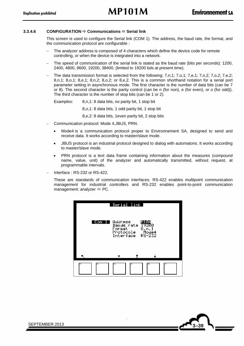
Duplication prohibited MP101M Environnement S.A
3–39SEPTEMBER 2013
3.3.4.6 CONFIGURATION Communications Serial link
This screen is used to configure the Serial link (COM 1). The address, the baud rate, the format, and the communication protocol are configurable :
The analyzer address is composed of 4 characters which define the device code for remote controlling, or when the device is integrated into a network.
The speed of communication of the serial link is stated as the baud rate (bits per seconds): 1200, 2400, 4800, 9600, 19200, 38400, (limited to 19200 bds at present time).
The data transmission format is selected from the following: 7,n,1; 7,o,1; 7,e,1; 7,n,2; 7,o,2; 7,e,2; 8,n,1; 8,o,1; 8,e,1; 8,n,2; 8,o,2; or 8,e,2. This is a common shorthand notation for a serial port parameter setting in asynchronous mode. The first character is the number of data bits (can be 7 or 8). The second character is the parity control (can be n (for non), e (for even), or o (for odd)). The third character is the number of stop bits (can be 1 or 2).
Examples: 8,n,1: 8 data bits, no parity bit, 1 stop bit
8,o,1: 8 data bits, 1 odd parity bit, 1 stop bit
8,e,2: 8 data bits, 1even parity bit, 2 stop bits
Communication protocol: Mode 4,JBUS, PRN.
Mode4 is a communication protocol proper to Environnement SA, designed to send and receive data. It works according to master/slave mode.
JBUS protocol is an industrial protocol designed to dialog with automatons. It works according to master/slave mode.
PRN protocol is a text data frame containing information about the measures (compound name, value, unit) of the analyzer and automatically transmitted, without request, at programmable intervals.
Interface : RS-232 or RS-422.
These are standards of communication interfaces. RS-422 enables multipoint communication management for industrial controllers and RS-232 enables point-to-point communication management: analyzer PC.

Environnement S.A MP101M Duplication prohibited
SEPTEMBER 20133–40
3.3.4.7 CONFIGURATION Communication Network configuration
To establish the communication between a local network and the analyzer it is necessary to configure an IP (Internet Protocol) address and a subnet mask that can be recognized by this analyzer.
For example if your PC uses the IP address 192.168.0.20 and the Subnet mask 255.255.0.0 it can only communicate with an analyzer that uses an IP address of the shape 192.168.x.x and the mask 255.255.0.0
This screen is used to configure the IP address and Mask of the analyzer:
HostName field: name of the analyzer to be recognized on the network (can not be changed by the user).
IP address field: enter an IP address that enables the communication between the analyzer and the computer.
Mask field: enter a mask that enables the communication between the analyzer and the computer.
Mac address field: physical address of the analyzer named Medium Access control (can not be changed by the user).
After any modification, go to the Validate field and switch it to ON.
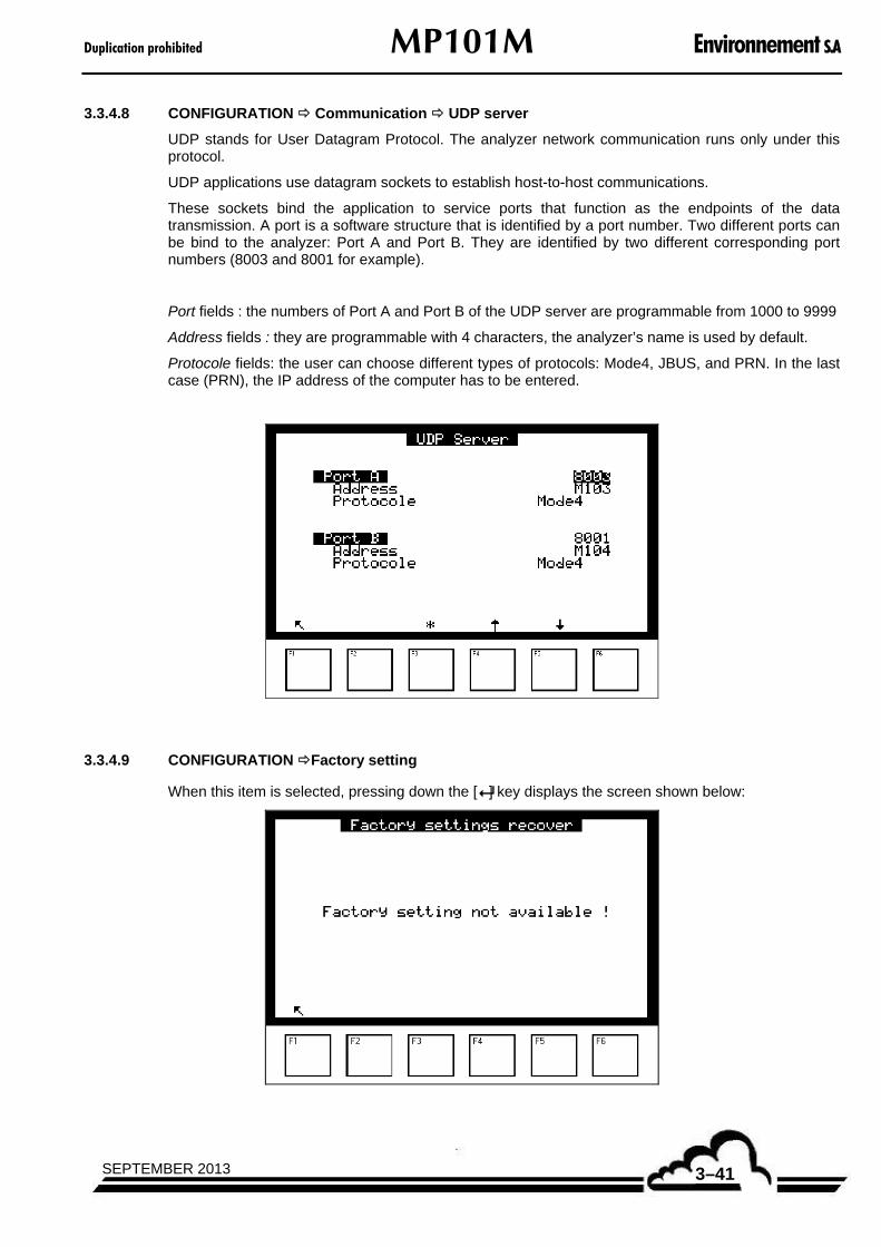
Duplication prohibited MP101M Environnement S.A
3–41SEPTEMBER 2013
3.3.4.8 CONFIGURATION Communication UDP server
UDP stands for User Datagram Protocol. The analyzer network communication runs only under this protocol.
UDP applications use datagram sockets to establish host-to-host communications.
These sockets bind the application to service ports that function as the endpoints of the data transmission. A port is a software structure that is identified by a port number. Two different ports can be bind to the analyzer: Port A and Port B. They are identified by two different corresponding port numbers (8003 and 8001 for example).
Port fields : the numbers of Port A and Port B of the UDP server are programmable from 1000 to 9999
Address fields : they are programmable with 4 characters, the analyzer’s name is used by default.
Protocole fields: the user can choose different types of protocols: Mode4, JBUS, and PRN. In the last case (PRN), the IP address of the computer has to be entered.
3.3.4.9 CONFIGURATION Factory setting
When this item is selected, pressing down the [] key displays the screen shown below:

Environnement S.A MP101M Duplication prohibited
SEPTEMBER 20133–42
3.3.5 STORED DATA
Stored data are accessed and managed directly from the Main menu. They are the average of analyzer measurements within a defined time interval.
This screen allows the parameter « Data recording period » to be set from 1 to 1440 min (i.e., 24 hours). It also displays memory status:
Free memory: from 32 MB in standard operation.
Storage : number of possible records, depending on free memory.
Autonomy: duration (days, months, years, hours, and minutes) that memory can store data, given the free space and data recording period.
Data can be edited in a table or histogram. This screen allows programming of the date and hour editing began, the date and hour editing ended, and the histogram column width.
Pressing down the [Menu] key changes the key functions to [Tabul.], [Hist.], [Print] and [RESET] as shown below.
[Tabul.] accesses the tabular data display, [Hist.] accesses the histogram data display, and [RESET] resets the memory to zero.
NOTE : To activate real time printing of stored data (by pressing down the [Print.] key), it is first necessary to program PRN in the Protocol field of the « CONFIGURATION Communications Serial links » screen.

Duplication prohibited MP101M Environnement S.A
3–43SEPTEMBER 2013
Editing stored data in tabular form:
This screen shows the list of stored data according to parameters defined in the previous screen. The running mode (measurement, zero, calibration, etc.) during a data storage period is coded in the status column. The meanings of the status codes are follows:
00 Measurement valid
01 Range 2 exceedence shooting
02 General alarm
20 Maintenance
40 Less than 2/3 of valid measurements during the average period
80 Power supply failure
FF Configuration modification
The displayed status code corresponds to the sum of the status codes (hexadecimal numbers) that occurs during the memorization period.
Definition of keys specific to this screen:
[] [] Select the previous or the next page.
[] Select stored data beginning or end.
[>>] Display other measurement channels if more than 3 channels are programmed in the «CONFIGURATION Measure channels» screen

Environnement S.A MP101M Duplication prohibited
SEPTEMBER 20133–44
Editing stored data in histogram form
This screen displays records in columns, with each column corresponding to the average measurements within the data-recording period as defined in the « STORED DATA » screen. Only one channel is displayed at a time. The information line gives the date and hour of the first record, the channel name, the full scale with unit and the data recording period (alternately blinking).
Definition of keys specific to this screen:
[] Return to previous menu.
[] Display previous stored data plot.
[] Display next stored data plot.
[] X 2 zoom in
[] 1/2 zoom out.
[>>] Select the next measure channel, when more than one measure channel is programmed.
Memory reset to zero
Pressing down the [Reset] key cancels the storage memory.
This action is irreversible: before to do it, the software asks you to confirm. If your answer is "YES", the software resets dates and hours of end edition to current dates and hours.
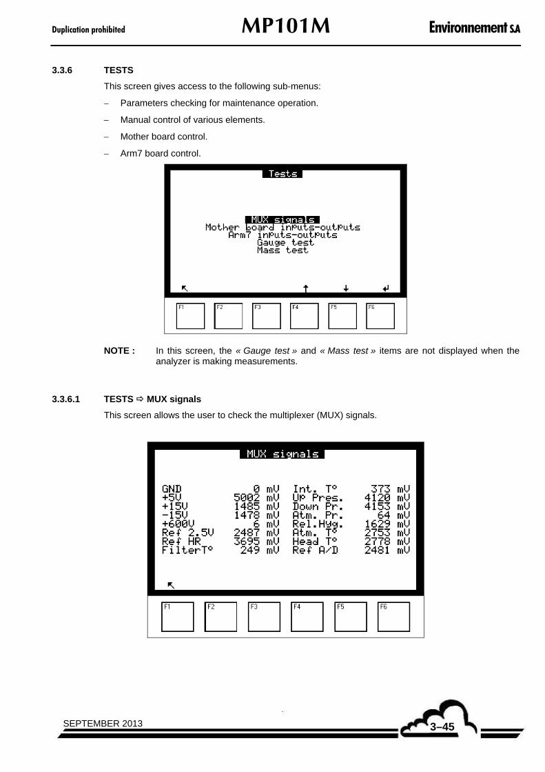
Duplication prohibited MP101M Environnement S.A
3–45SEPTEMBER 2013
3.3.6 TESTS
This screen gives access to the following sub-menus:
Parameters checking for maintenance operation.
Manual control of various elements.
Mother board control.
Arm7 board control.
NOTE : In this screen, the « Gauge test » and « Mass test » items are not displayed when the analyzer is making measurements.
3.3.6.1 TESTS MUX signals
This screen allows the user to check the multiplexer (MUX) signals.

Environnement S.A MP101M Duplication prohibited
SEPTEMBER 20133–46
Table 3-2 – Multiplexer (MUX) signals (Acceptable limits on channel 1 to 16 of the multiplexer)
Channel
Abbreviations (Displays)
Parameters Lower limit
Normal Upper limit
01 0 V Ground - 50 mV 0 mV + 50 mV
02 + 5 V Checking of + 5 V power supply + 4800 mV + 5000 mV + 5200 mV
03 + 15 V Checking of + 15 V power supply + 1450 mV + 1500 mV + 1550 mV
04* - 15 V Checking of - 15 V power supply + 1300 mV + 1500 mV + 1700 mV
05** + 600 V Checking of G.M. counter power supply. + 500.0 V 000.0 V 600.0 V
+ 700.0 V
06 Ref. 2,5 V Voltage reference 2,5 V + 2485 mV + 2500 mV + 2515 mV
07 Ref. HR Voltage reference of probe humidity probe + 3650 mV + 3700 mV + 3750 mV
08 Filter T° Filter temperature measured under the G.M. counter
+ 100 mV + 250 mV + 400 mV
09 Int. T° Internal temperature of the analyzer, measured on the mother board
+ 100 mV + 250 mV + 400 mV
10 Up Pr. Upstream pressure + 3880 mV + 4130 mV + 4380 mV
11 Down Pr. Downstrem pressure + 3880 mV + 4130 mV + 4380 mV
12 Atm. Pr. Atmospheric pressure + 3880 mV + 4130 mV + 4380 mV
13 Rel. hyg. Relative humidity (if RST option « ON ») + 780 mV + 2350 mV + 3910 mV
14 Atm. T°. Atmospheric temperature (if RST option « ON »)
- + 2750 mV -
15 Head T° Head temperature (if RST option « ON ») - + 2750 mV -
16 Ref A/D Reference of the A/D converter + 2485 mV + 2500 mV + 2515 mV
(*) Channel 04 = The « -15V signal » of the multiplexer is an indicating measurement, but not a direct measurement of the – 15V voltage really present on the board and which can be measured with a voltmeter. The tolerance on the real – 15 V is ± 50 mV.
(**) Channel 05 = 600 V effective only when the (GM) counter is supplied.

Duplication prohibited MP101M Environnement S.A
3–47SEPTEMBER 2013
3.3.6.2 TESTS Arm7 inputs - outputs
When this menu is available, no backup of output modification is carried out.
This menu displays the status of the switches on the DNP-Arm7 board. It enables testing of the ON/OFF switch of the Back light of the LCD.
The option Life del (LED lifetime) allows testing of a LED in order to show the DNP-Arm7 activity when no LCD display is available.
SW1 indicates whether the analyzer is or is not in maintenance mode.
SW2, SW3, WS4 are not used.
SW5 shows whether WatchDog is active or not.
SW6 indicates either the standard configuration or the configuration of the application.
SW7 shows whether AutoStart is ON or OFF.
SW8 and SW9 are hardware features not displayed on the screen but indicate the following:
SW8: When ON, connects the battery to Arm7 board timekeeper.
When OFF, resets timekeeper.
SW9: Normally OFF.
When ON, allows a reset of the DNP-Arm7 board.
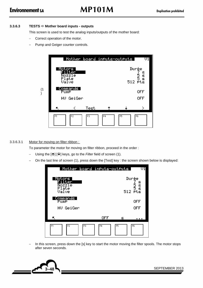
Environnement S.A MP101M Duplication prohibited
SEPTEMBER 20133–48
3.3.6.3 TESTS Mother board inputs - outputs
This screen is used to test the analog inputs/outputs of the mother board:
Correct operation of the motor.
Pump and Geiger counter controls.
(1)
3.3.6.3.1 Motor for moving on filter ribbon :
To parameter the motor for moving on filter ribbon, proceed in the order :
Using the [] [] keys, go to the Filter field of screen (1).
On the last line of screen (1), press down the [Test] key : the screen shown below is displayed:
In this screen, press down the [s] key to start the motor moving the filter spools. The motor stops after seven seconds.
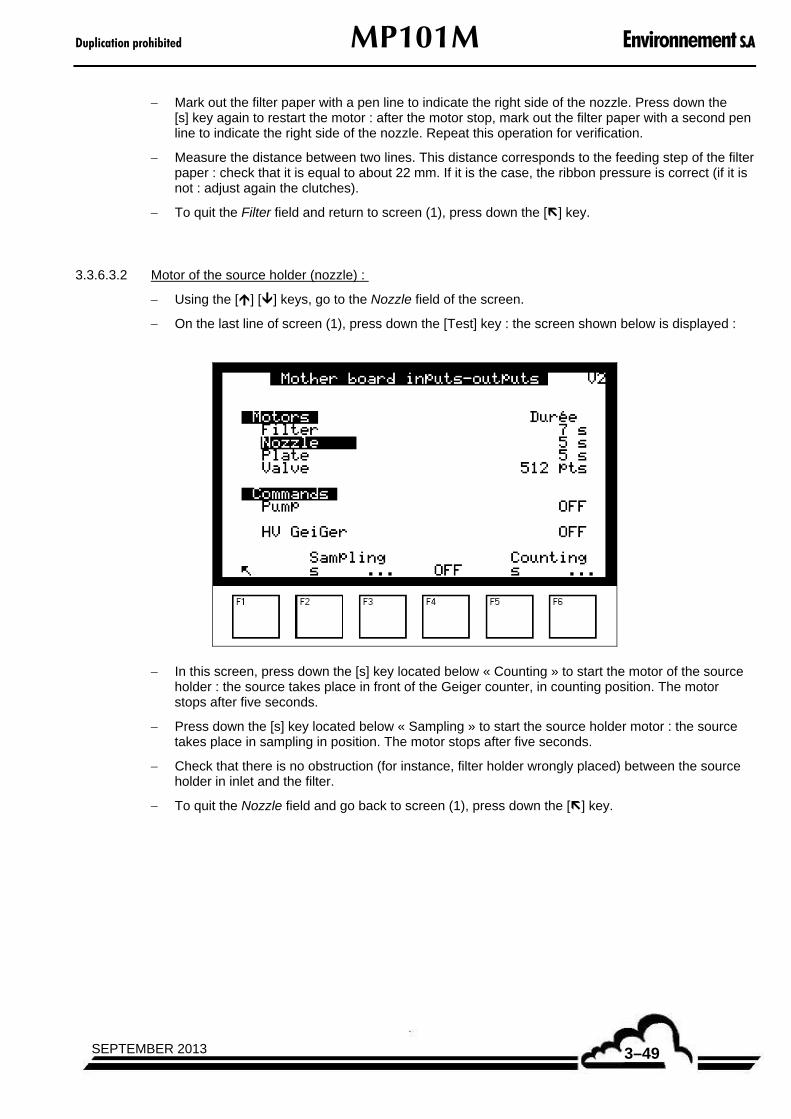
Duplication prohibited MP101M Environnement S.A
3–49SEPTEMBER 2013
Mark out the filter paper with a pen line to indicate the right side of the nozzle. Press down the [s] key again to restart the motor : after the motor stop, mark out the filter paper with a second pen line to indicate the right side of the nozzle. Repeat this operation for verification.
Measure the distance between two lines. This distance corresponds to the feeding step of the filter paper : check that it is equal to about 22 mm. If it is the case, the ribbon pressure is correct (if it is not : adjust again the clutches).
To quit the Filter field and return to screen (1), press down the [] key.
3.3.6.3.2 Motor of the source holder (nozzle) :
Using the [] [] keys, go to the Nozzle field of the screen.
On the last line of screen (1), press down the [Test] key : the screen shown below is displayed :
In this screen, press down the [s] key located below « Counting » to start the motor of the source holder : the source takes place in front of the Geiger counter, in counting position. The motor stops after five seconds.
Press down the [s] key located below « Sampling » to start the source holder motor : the source takes place in sampling in position. The motor stops after five seconds.
Check that there is no obstruction (for instance, filter holder wrongly placed) between the source holder in inlet and the filter.
To quit the Nozzle field and go back to screen (1), press down the [] key.

Environnement S.A MP101M Duplication prohibited
SEPTEMBER 20133–50
3.3.6.3.3 Moving plate motor:
Using the [] [] keys, go to the Plate field of screen (1).
On the last line of screen (1), press down the [Test] key : the screen shown below is displayed :
In this screen, press down the [s] key located below « Moving up » to start up the plate motor : the plate moves up. The motor stops after five seconds.
Press down the [s] key located below « Moving down » to start up the plate motor : the plate moves down. The motor stops after five seconds.
Check that there is no obstruction while the plate is moving up and moving down.
To quit the Plate field and go back to screen (1), press down the [] key.
NOTE : The […] key enables the ribbon to advance ad infinitum. The [OFF] key enables to stop this movement.

Duplication prohibited MP101M Environnement S.A
3–51SEPTEMBER 2013
3.3.6.3.4 Valve motor :
Using the [] [] keys, go to the Valve field of screen (1).
On the last line of screen (1), press down the [Test] key : the « Valve » screen is displayed.
In this screen, press down the [Pts] key located under « Opening » to start up the valve motor in Opening. Check that the valve motor turns correctly towards the left (user being placed in front of the valve).
Then press down the [Pts] key located under « Closing » to start up the valve motor in Closing. Check that the motor valve turns correctly towards the right (user being placed in front of the valve).
NOTE : The [Max] keys located under « Opening » and « Closing » enable to completely open and close the valve.
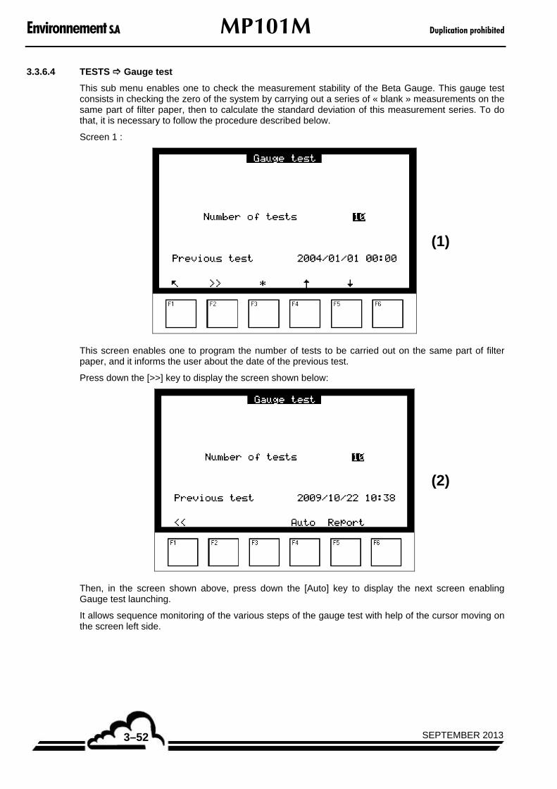
Environnement S.A MP101M Duplication prohibited
SEPTEMBER 20133–52
3.3.6.4 TESTS Gauge test
This sub menu enables one to check the measurement stability of the Beta Gauge. This gauge test consists in checking the zero of the system by carrying out a series of « blank » measurements on the same part of filter paper, then to calculate the standard deviation of this measurement series. To do that, it is necessary to follow the procedure described below.
Screen 1 :
(1)
This screen enables one to program the number of tests to be carried out on the same part of filter paper, and it informs the user about the date of the previous test.
Press down the [>>] key to display the screen shown below:
(2)
Then, in the screen shown above, press down the [Auto] key to display the next screen enabling Gauge test launching.
It allows sequence monitoring of the various steps of the gauge test with help of the cursor moving on the screen left side.
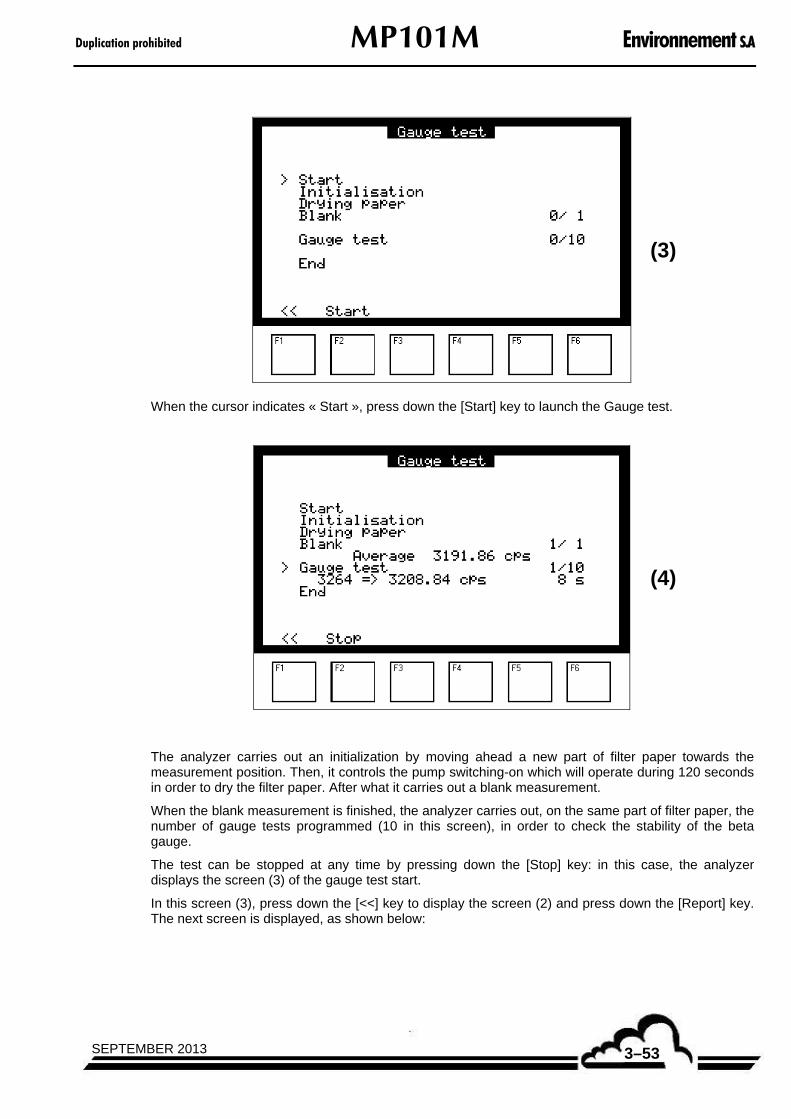
Duplication prohibited MP101M Environnement S.A
3–53SEPTEMBER 2013
(3)
When the cursor indicates « Start », press down the [Start] key to launch the Gauge test.
(4)
The analyzer carries out an initialization by moving ahead a new part of filter paper towards the measurement position. Then, it controls the pump switching-on which will operate during 120 seconds in order to dry the filter paper. After what it carries out a blank measurement.
When the blank measurement is finished, the analyzer carries out, on the same part of filter paper, the number of gauge tests programmed (10 in this screen), in order to check the stability of the beta gauge.
The test can be stopped at any time by pressing down the [Stop] key: in this case, the analyzer displays the screen (3) of the gauge test start.
In this screen (3), press down the [<<] key to display the screen (2) and press down the [Report] key. The next screen is displayed, as shown below:
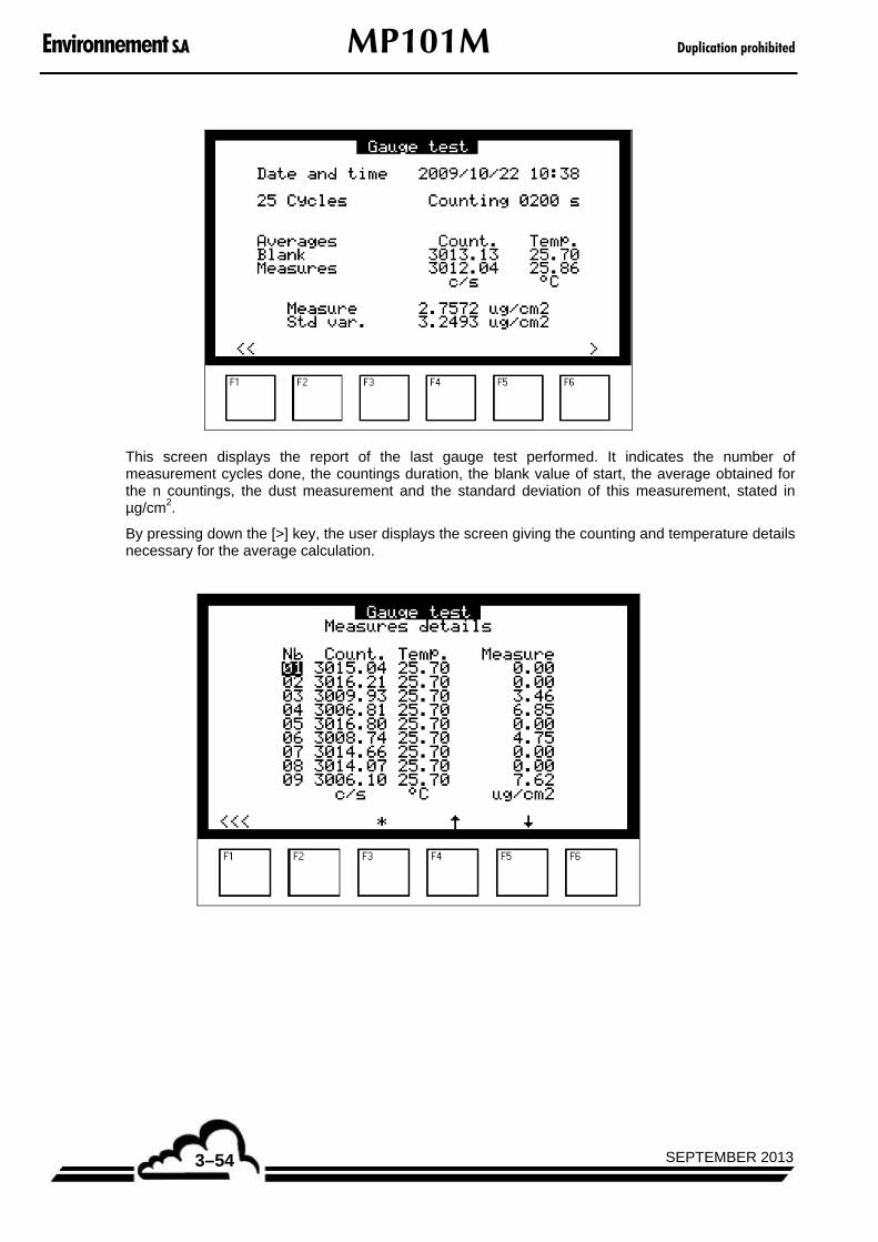
Environnement S.A MP101M Duplication prohibited
SEPTEMBER 20133–54
This screen displays the report of the last gauge test performed. It indicates the number of measurement cycles done, the countings duration, the blank value of start, the average obtained for the n countings, the dust measurement and the standard deviation of this measurement, stated in µg/cm2.
By pressing down the [>] key, the user displays the screen giving the counting and temperature details necessary for the average calculation.

Duplication prohibited MP101M Environnement S.A
3–55SEPTEMBER 2013
3.3.6.5 TESTS Mass test
This sub menu enables one to check the mass measurement stability of a reference gauge. The purpose of the test is to calculate the measurement accuracy and repeatability for a reference gauge whose density was predefined.
For that, it is necessary to follow the procedure described below :
Screen 1 :
(1)
This screen enables one to program the number of tests to be carried out on the same part of filter, and informs the user about the date the last test took place.
Press down the [>>] key to display the screen shown below :
(2)
Then, in this screen, press down the [Auto] key to display the following screen enabling to launch the mass test.
In this screen, the user can monitor the sequence of the various steps of the mass test thanks to the cursor moving on the screen left side.

Environnement S.A MP101M Duplication prohibited
SEPTEMBER 20133–56
(3)
When the cursor indicates « Start », press down the [Start] key to launch a mass test.
The screen shown above is replaced by this one :
(4)
The analyzer carries out an initialization by moving ahead a new part of filter paper towards the measurement position. Then, it controls the pump switching on which will operate during 120 seconds in order to dry the filter paper. After what, it carries out a blank measurement.
When the blank measurement is finished, the cursor moves to « Insert reference gauge » position and this message blinks.
The user has to place the reference gauge, guided by the two pins, until hearing a click sound when it arrives in limit stop (see Figure 3–4). Once the reference gauge is installed, the user has to validate this operation by pressing down the F3 key.

Duplication prohibited MP101M Environnement S.A
3–57SEPTEMBER 2013
Figure 3–4 – Putting in place the reference gauge
Then the analyzer carries out the number of mass measurements programmed (10 in this screen) on the reference gauge. When these 10 measurements are finished, the cursor moves to the « Pull out reference gauge » position, and this message blinks : the user must remove the reference gauge and validate the operation by pressing down the F3 key. The cursor can then move to the « End » position, which indicates that the test is finished.
The test can be stopped at any time by pressing down the [Stop] key : in this case, the analyzer displays the screen (3) of mass test start.
In this screen (3), press down the [<<] key to display the screen (2) and press down the [Report] key. The next screen is displayed as shown below:
This screen displays the report of the last mass test carried out. It indicates the number of measurement cycles done, the counting duration, the starting blank value, the average countings obtained for the n measurements of the reference gauge, the value of the reference gauge and its standard deviation, stated in µg/cm2.
By pressing down the [>] key, the user displays the screen giving details of the counting values and the measurement obtained on the reference gauge.
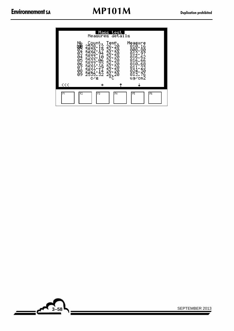
Environnement S.A MP101M Duplication prohibited
SEPTEMBER 20133–58
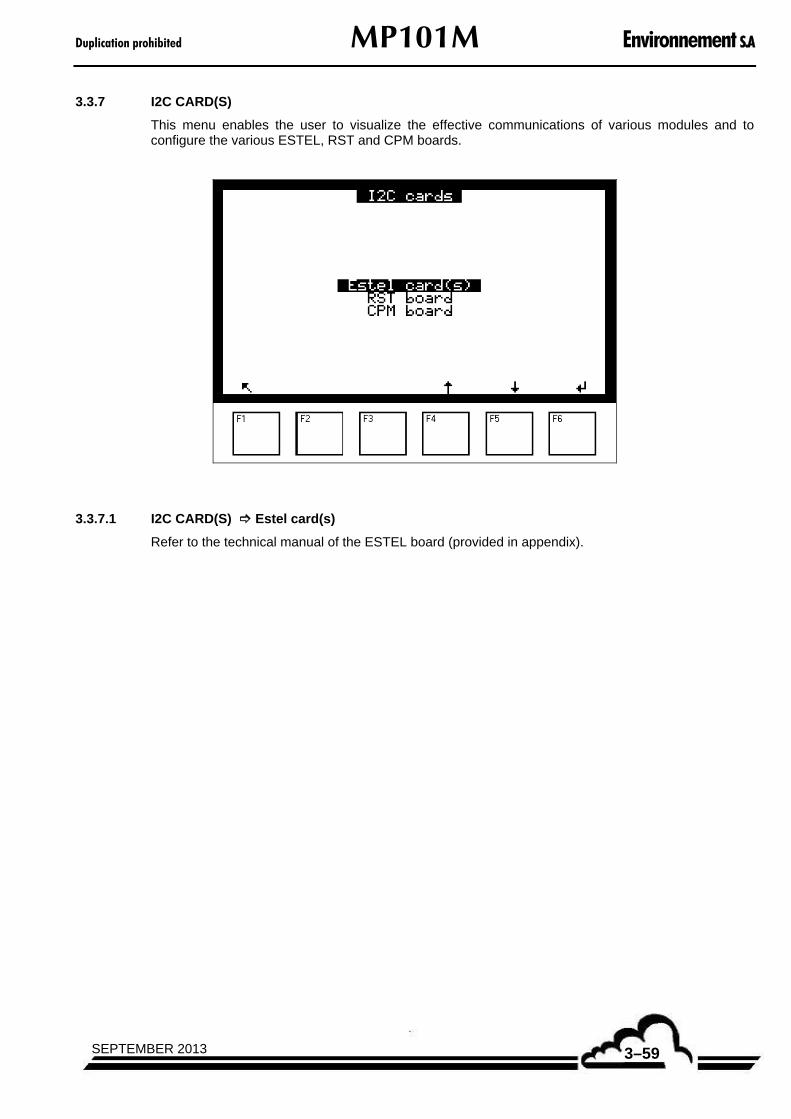
Duplication prohibited MP101M Environnement S.A
3–59SEPTEMBER 2013
3.3.7 I2C CARD(S)
This menu enables the user to visualize the effective communications of various modules and to configure the various ESTEL, RST and CPM boards.
3.3.7.1 I2C CARD(S) Estel card(s)
Refer to the technical manual of the ESTEL board (provided in appendix).

Environnement S.A MP101M Duplication prohibited
SEPTEMBER 20133–60
3.3.7.2 I2C CARD(S) RST board
This screen allows the user to test the RST line and RST board operation, and to linearize the following parameters:
Atmospheric temperature.
Temperature of the sampling head.
Relative humidity at time of sampling.
For each parameter, it is possible to modify the A and B values.
For each X parameter, the value indicated on the left is the signal value stated in mV, from which it is necessary to substract the reference voltage value. The value indicated on the right is the corresponding value stated in the standard measurement unit.
The Head heating field is used to test the heating control of the head. To activate this control, press down the [] key in order to switch OFF to ON.
The Other cmd. field is used to test the operational control, when it is available on the RST board. To activate this control, press down the [] key in order to switch OFF to ON.
REMARK : During the first starting up, a test report is provided with the meteo sensors of the RST line. The A and B factors enabling to linearize the relative humidity value, stated in %, can be calculated with the help of the following table :
Numéro du capteur
Channel ...........................................
Pente (format xx,xxx)
Slope S = ..................................... mV / % RH
Offset à zéro (format xx,xxx)
Zero offset Z = ..................................... V
With : S
A1
and S
ZB
1000

Duplication prohibited MP101M Environnement S.A
3–61SEPTEMBER 2013
3.3.7.3 I2C CARD(S) CPM board
This sub menu is available in the « I2C Card(s) » menu, if the CPM option is available into the analyzer.
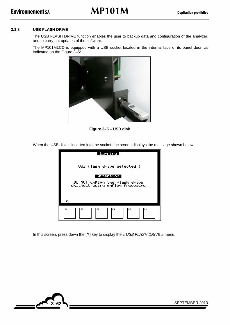
Environnement S.A MP101M Duplication prohibited
SEPTEMBER 20133–62
3.3.8 USB FLASH DRIVE
The USB FLASH DRIVE function enables the user to backup data and configuration of the analyzer, and to carry out updates of the software.
The MP101MLCD is equipped with a USB socket located in the internal face of its panel door, as indicated on the Figure 3–5:
Figure 3–5 – USB disk
When the USB disk is inserted into the socket, the screen displays the message shown below :
In this screen, press down the [] key to display the « USB FLASH DRIVE » menu.

Duplication prohibited MP101M Environnement S.A
3–63SEPTEMBER 2013
3.3.8.1 USB FLASH DRIVE Flash drive information
The « USB FLASH DRIVE Flash drive information » screen gives information about the storage capacity on the USB disk as well as its free space.
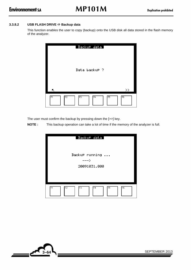
Environnement S.A MP101M Duplication prohibited
SEPTEMBER 20133–64
3.3.8.2 USB FLASH DRIVE Backup data
This function enables the user to copy (backup) onto the USB disk all data stored in the flash memory of the analyzer.
The user must confirm the backup by pressing down the [>>] key.
NOTE : This backup operation can take a lot of time if the memory of the analyzer is full.
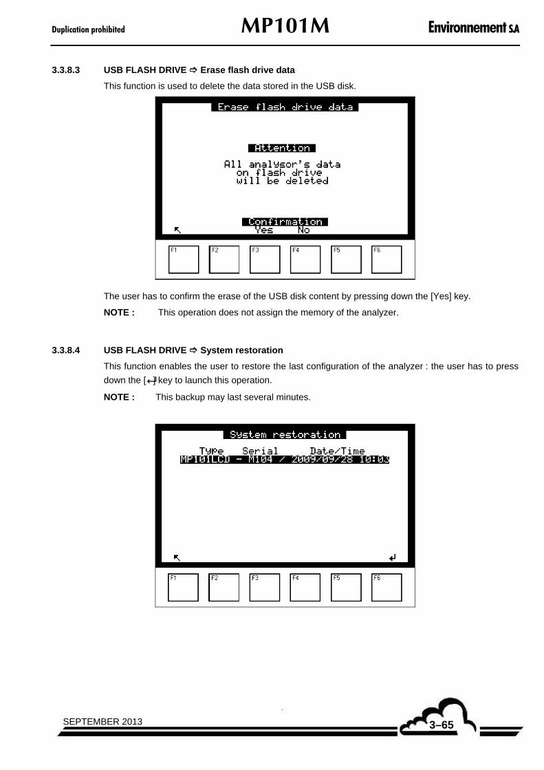
Duplication prohibited MP101M Environnement S.A
3–65SEPTEMBER 2013
3.3.8.3 USB FLASH DRIVE Erase flash drive data
This function is used to delete the data stored in the USB disk.
The user has to confirm the erase of the USB disk content by pressing down the [Yes] key.
NOTE : This operation does not assign the memory of the analyzer.
3.3.8.4 USB FLASH DRIVE System restoration
This function enables the user to restore the last configuration of the analyzer : the user has to press
down the [] key to launch this operation.
NOTE : This backup may last several minutes.
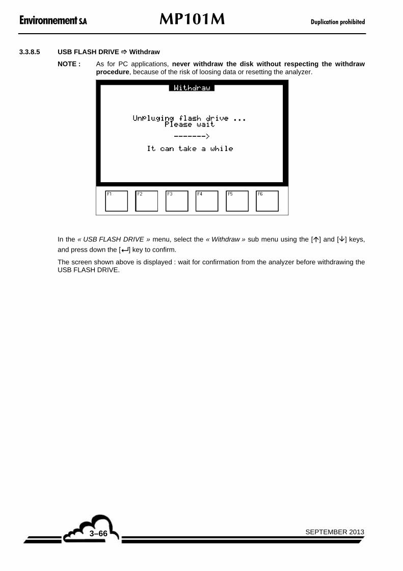
Environnement S.A MP101M Duplication prohibited
SEPTEMBER 20133–66
3.3.8.5 USB FLASH DRIVE Withdraw
NOTE : As for PC applications, never withdraw the disk without respecting the withdraw procedure, because of the risk of loosing data or resetting the analyzer.
In the « USB FLASH DRIVE » menu, select the « Withdraw » sub menu using the [] and [] keys,
and press down the [ ] key to confirm.
The screen shown above is displayed : wait for confirmation from the analyzer before withdrawing the USB FLASH DRIVE.

Duplication prohibited MP101M Environnement S.A
4–1SEPTEMBER 2013
CHAPTER 4
PREVENTIVE MAINTENANCE
4.1. SAFETY INSTRUCTIONS 4–2
4.2. MAINTENANCE CALENDAR 4–3
4.3. MAINTENANCE OPERATION SHEETS 4–3
4.4. EQUIPMENT NECESSARY FOR MAINTENANCE 4–27
Figure 4–1 – Diagram of the Picolino pump 4–5 Figure 4–2 – Diagram of the KNF pump 4–7 Figure 4–3 – Cleaning of the sampling heads PM10 EN12341 and PM2.5 EN14907 4–9 Figure 4–4 – Cleaning of the US-EPA standardized PM10 inlet 4–10 Figure 4–5 – Cleaning of the US-EPA standardized VSCCTM 4–11

Environnement S.A MP101M Duplication prohibited
SEPTEMBER 20134–2
4. PREVENTIVE MAINTENANCE
4.1. SAFETY INSTRUCTIONS
The user must follow these safety instructions at all times:
– Always turn off the power supply when performing analyzer maintenance.
– Take the necessary precautions when handling dangerous products (example: gloves, protective mask, etc.).
– Personnel should be trained in the proper operation of this equipment before attempting to operate it.
– The manufacturer shall not be responsible for any adverse outcomes resulting from the following:
Use of the monitor by unqualified service personnel.
Use of the monitor under conditions other than those specified in this document.
Use of components or accessories not manufactured by Environnement SA. Failure to use recommended parts may reduce the safety features.
Use of this equipment in a manner not approved by Environnement SA as it can cause harm to the equipment or operating personnel. Inappropriate maintenance of the analyzer.
– A periodic inspection is required.
REMINDER
Refer to Chapter 0, safety guidelines section, pages 0-10 to 0-18.

Duplication prohibited MP101M Environnement S.A
4–3SEPTEMBER 2013
4.2. MAINTENANCE CALENDAR
By its design, the MP101M requires very limited maintenance. However, the unit must be regularly serviced to ensure proper performance over time. The routine maintenance schedule shown below is an example, and this schedule can vary according to operating conditions.
Nature of operations Periodicity Sheet N°
– Check of Picolino pump assembly 1 year 4.3.1
– Check of KNF pump assembly 1 year 4.3.2
– Sampling heads cleaning 1 month 4.3.3
– Multiplexer (MUX) signals verification 3 months 4.3.4
– Replacement of filter ribbon 1 to 3 years 4.3.5
– Verification of pressure exerted on the filter 1 year 4.3.6
– Flow rate and leak rate tests 3 months 4.3.7
– Calibration of sampling flow rate 6 months 4.3.8
– Beta gauge calibration 6 months 4.3.9
– Contamination test 1 month 4.3.10
– Beta gauge check (gauge test, mass test) 6 months 4.3.11
– Verification / Replacement of T°C and RH sensors 6 months 4.3.12
4.3. MAINTENANCE OPERATION SHEETS
As indicated in the previous page:
WARNINGS
– Refer to chapter 0, safety guidelines section, pages 0-10 to 0-18.

Environnement S.A MP101M Duplication prohibited
SEPTEMBER 20134–4
MAINTENANCE SHEET
Monitor serial No.: OPERATION SHEET : 4.3.1
Scope : Check of Picolino pump assembly (impellers pump)
PAGE : 1/2 Periodicity : 1 year
Replacement parts : Maintenance kit of PICOLINO VTE3 pump assembly ref. SAV-K-000145
Dates
Procedure (see Figure 4–1) :
1/ Before any intervention, stop the measurement cycle and disconnect the pump from the analyzer.
2/ Remove the body cover (4).
3/ Remove the filtering cartridge (5) as well as an impeller (3) to check their wearing status.
4/ The filtering cartridges (5) must be cleaned according to the dust amount :
– Purge the filter with compressed air from inside towards outside (do not wash it).
– Replace the clogged or oily cartridges by new ones.
5/ Impellers wear away (3) because of friction against the wall of the pump body :
– Check the impeller size : due to wear, the size of the impeller is smaller than if it was new.
– During replacement, purge the pump body with compressed dry air.
6/ If necessary, replace the seals using ones provided in the maintenance kit. See (6) (7) (34) of Figure 4–1.
7/ Replace the body cover.

Duplication prohibited MP101M Environnement S.A
4–5SEPTEMBER 2013
MAINTENANCE SHEET
Monitor serial No.: OPERATION SHEET : 4.3.1
Scope : Check of Picolino pump assembly (impellers pump)
PAGE : 2/2 Periodicity : 1 year
Replacement parts : Maintenance kit of PICOLINO VTE3 pump assembly ref. SAV-K-000145
Figure 4–1 – Diagram of the Picolino pump
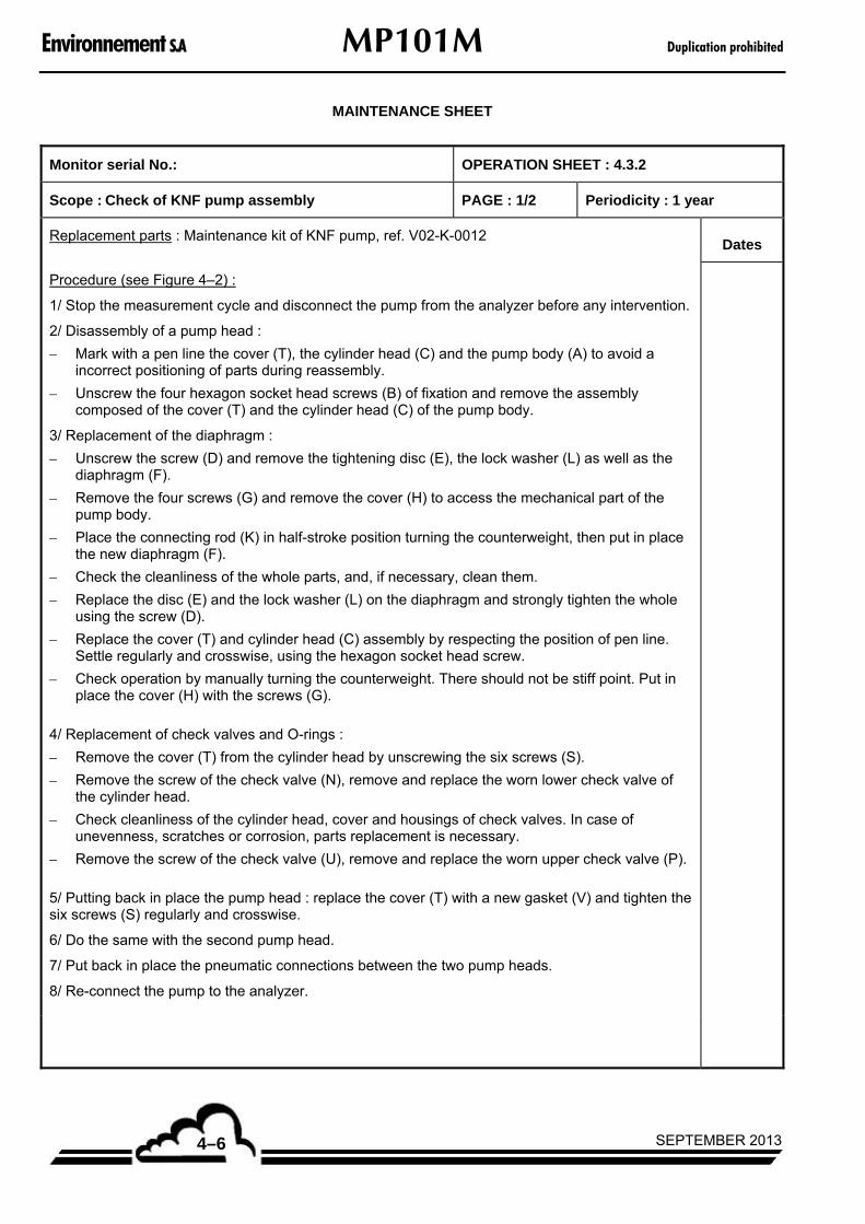
Environnement S.A MP101M Duplication prohibited
SEPTEMBER 20134–6
MAINTENANCE SHEET
Monitor serial No.: OPERATION SHEET : 4.3.2
Scope : Check of KNF pump assembly PAGE : 1/2 Periodicity : 1 year
Replacement parts : Maintenance kit of KNF pump, ref. V02-K-0012 Dates
Procedure (see Figure 4–2) :
1/ Stop the measurement cycle and disconnect the pump from the analyzer before any intervention.
2/ Disassembly of a pump head :
– Mark with a pen line the cover (T), the cylinder head (C) and the pump body (A) to avoid a incorrect positioning of parts during reassembly.
– Unscrew the four hexagon socket head screws (B) of fixation and remove the assembly composed of the cover (T) and the cylinder head (C) of the pump body.
3/ Replacement of the diaphragm :
– Unscrew the screw (D) and remove the tightening disc (E), the lock washer (L) as well as the diaphragm (F).
– Remove the four screws (G) and remove the cover (H) to access the mechanical part of the pump body.
– Place the connecting rod (K) in half-stroke position turning the counterweight, then put in place the new diaphragm (F).
– Check the cleanliness of the whole parts, and, if necessary, clean them.
– Replace the disc (E) and the lock washer (L) on the diaphragm and strongly tighten the whole using the screw (D).
– Replace the cover (T) and cylinder head (C) assembly by respecting the position of pen line. Settle regularly and crosswise, using the hexagon socket head screw.
– Check operation by manually turning the counterweight. There should not be stiff point. Put in place the cover (H) with the screws (G).
4/ Replacement of check valves and O-rings :
– Remove the cover (T) from the cylinder head by unscrewing the six screws (S).
– Remove the screw of the check valve (N), remove and replace the worn lower check valve of the cylinder head.
– Check cleanliness of the cylinder head, cover and housings of check valves. In case of unevenness, scratches or corrosion, parts replacement is necessary.
– Remove the screw of the check valve (U), remove and replace the worn upper check valve (P).
5/ Putting back in place the pump head : replace the cover (T) with a new gasket (V) and tighten the six screws (S) regularly and crosswise.
6/ Do the same with the second pump head.
7/ Put back in place the pneumatic connections between the two pump heads.
8/ Re-connect the pump to the analyzer.
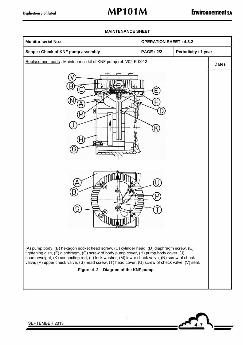
Duplication prohibited MP101M Environnement S.A
4–7SEPTEMBER 2013
MAINTENANCE SHEET
Monitor serial No.: OPERATION SHEET : 4.3.2
Scope : Check of KNF pump assembly PAGE : 2/2 Periodicity : 1 year
Replacement parts : Maintenance kit of KNF pump ref. V02-K-0012 Dates
(A) pump body, (B) hexagon socket head screw, (C) cylinder head, (D) diaphragm screw, (E) tightening disc, (F) diaphragm, (G) screw of body pump cover, (H) pump body cover, (J) counterweight, (K) connecting rod, (L) lock washer, (M) lower check valve, (N) screw of check valve, (P) upper check valve, (S) head screw, (T) head cover, (U) screw of check valve, (V) seal.
Figure 4–2 – Diagram of the KNF pump

Environnement S.A MP101M Duplication prohibited
SEPTEMBER 20134–8
MAINTENANCE SHEET
Monitor serial No.: OPERATION SHEET : 4.3.3
Scope : Sampling heads cleaning PAGE : 1/4 Periodicity : 1 month
Dates European standardized sampling heads : (Figure 4–3)
– Loosen the settling ring and separate the head from the sampling tube by simple vertical pulling.
– Remove the cover and the protection grid.
– Brush the grid in order to remove any foreign body.
– Remove the body from the head (a).
– Clean the impact plate (with alcohol if necessary to remove fat) (b).
– Pass a channel cleaning brush into the sampling channel.
– Clean the eight orifices with compressed air (c).
– Coat the impaction plate with silicon grease for vacuum.
US-EPA standardized PM10 inlet: (Figure 4–4)
– Separate the head from the sampling tube by simple vertical pulling.
– Empty and clean the decantation bottle.
– Brush the inlet grid.
– Put down the head by simple vertical pulling (a).
– Pass a channel cleaning brush into the sampling channel.
– Clean the three orifices with compressed air (b).
– Remove the four screws from the top of the PM10 inlet (c).
– Remove the top part (d).
– Clean the inside and outside of the dirty parts with a soft cloth moistened with alcohol (e).
– Dry the parts.
– When cleaning is finished, reassemble the US-EPA standardized PM10 inlet.
US-EPA standardized VSCCTM: (Figure 4–5)
– Disassemble the various parts of the VSCCTM as shown in (a). No tool is required.
– Clean the inside and outside (b) of the dirty parts with a soft cloth moistened with alcohol.
– Dry the parts and check the o-rings (change them if necessary).
– Reassemble VSCCTM, as shown in (c).
– Tools required
Cylinder of compressed air,
Nylon brush, soft cloth.
Silicon grease for vacuum
Alcool

Duplication prohibited MP101M Environnement S.A
4–9SEPTEMBER 2013
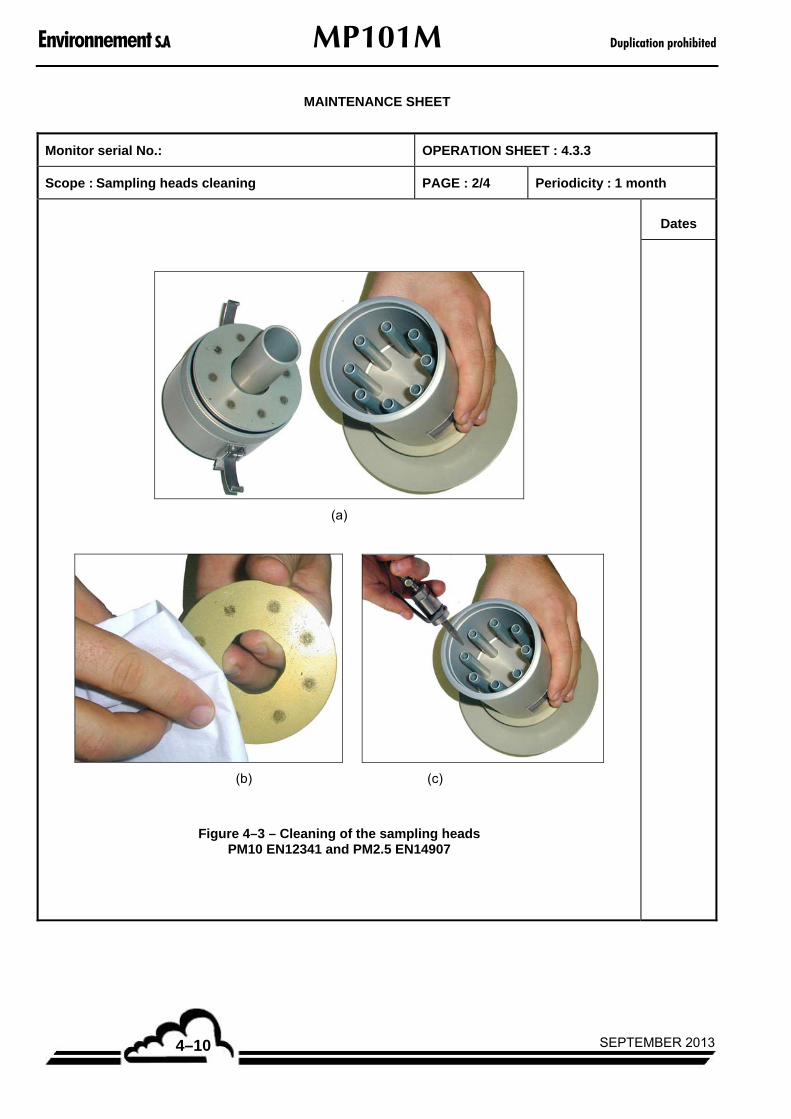
Environnement S.A MP101M Duplication prohibited
SEPTEMBER 20134–10
MAINTENANCE SHEET
Monitor serial No.: OPERATION SHEET : 4.3.3
Scope : Sampling heads cleaning PAGE : 2/4 Periodicity : 1 month
Dates
(a)
(b) (c)
Figure 4–3 – Cleaning of the sampling heads PM10 EN12341 and PM2.5 EN14907
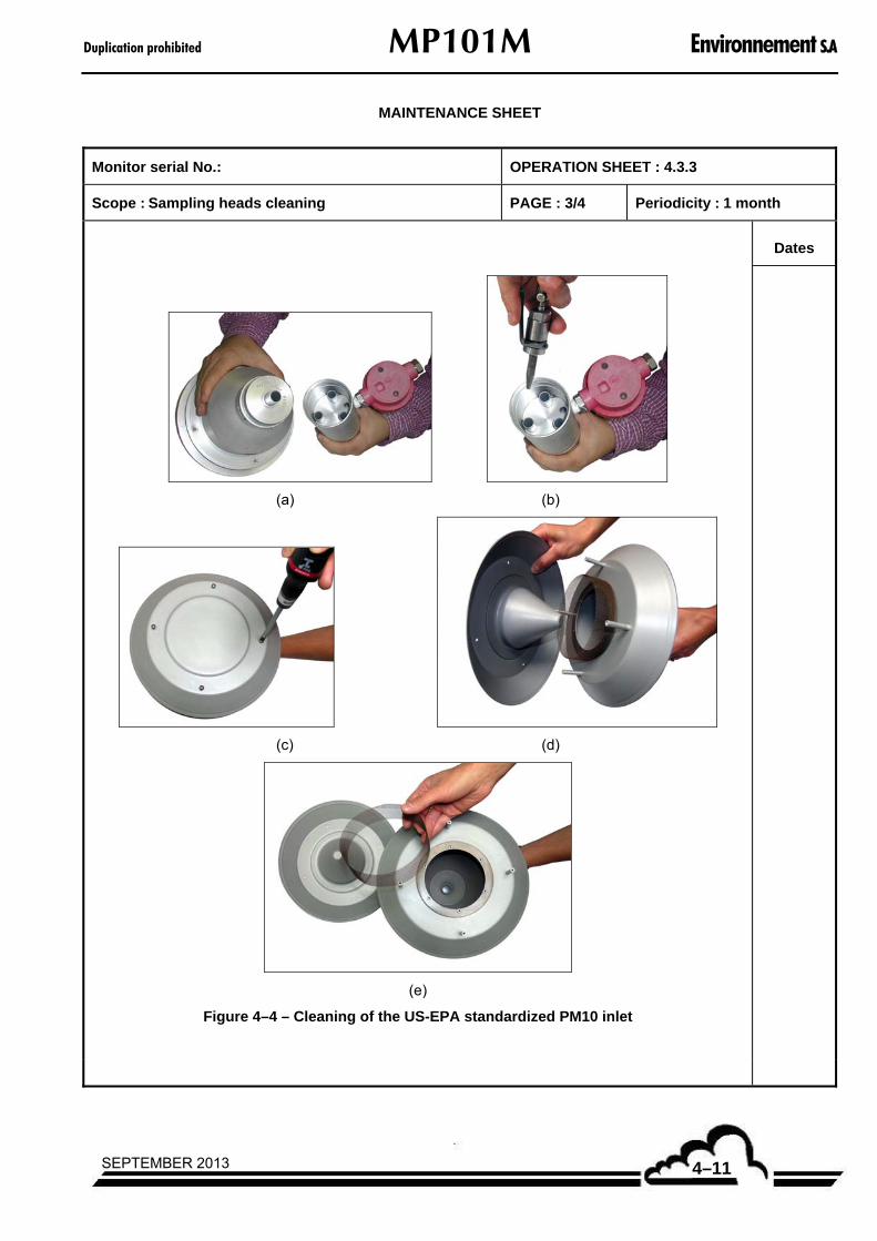
Duplication prohibited MP101M Environnement S.A
4–11SEPTEMBER 2013
MAINTENANCE SHEET
Monitor serial No.: OPERATION SHEET : 4.3.3
Scope : Sampling heads cleaning PAGE : 3/4 Periodicity : 1 month
Dates
(a) (b)
(c) (d)
(e)
Figure 4–4 – Cleaning of the US-EPA standardized PM10 inlet

Environnement S.A MP101M Duplication prohibited
SEPTEMBER 20134–12
MAINTENANCE SHEET
Monitor serial No.: OPERATION SHEET : 4.3.3
Scope : Sampling heads cleaning PAGE : 4/4 Periodicity : 1 month
Dates
(a)
(b) (c)
Figure 4–5 – Cleaning of the US-EPA standardized VSCCTM

Duplication prohibited MP101M Environnement S.A
4–13SEPTEMBER 2013
MAINTENANCE SHEET
Monitor serial No.: OPERATION SHEET : 4.3.4
Scope : Multiplexer (MUX) signals verification PAGE : 1/1 Periodicity : 30months
Dates
Procedure :
1/ Go to the « TESTS MUX Signals » screen.
2/ Compare the voltages values for each multiplexer inlet with the values written down in the control sheet provided with the analyzer.
Multiplexer (MUX) signals reading
1 2 3 4 5 6 8 9 10 11 12 16 Dates
Ground +5V +15V -15V 600V Ref. 2.5V
T° Filter Int. T°CUpstr.press.
Downst press.
Atm. Press.
A/D Ref.
– Tools required
None.
Environnement S.A MP101M Duplication prohibited
SEPTEMBER 20134–14
Page intentionally left blank

Duplication prohibited MP101M Environnement S.A
4–15SEPTEMBER 2013
MAINTENANCE SHEET
Monitor serial No.: OPERATION SHEET : 4.3.5
Scope : Replacement of filter ribbon PAGE : 1/3 Periodicity : from 1 to 3 years
Periodicity: WHEN THE alarm « PAPER END » IS DISPLAYED (1 TO 3 YEARS ACCORDING TO PROGRAMMING
OF THE CYCLE DURATION). Dates
Procedure :
1/ Stop any measurement in progress, if necessary.
2/ Go to the « TESTS Mother board Inputs - Outputs » screen and make the plate moves down.
3/ Open the door of the analyzer using the knurled button located on the left.
4/ Lift up the disengageable pinch roller as shown in the just below picture.
5/ Unscrew the stop button and remove the end plates of the take-up and pay-out reels, as shown in the two just below pictures.
6/ Remove the worn roll, recover the paperboard mandrel of the pay-out and place it on the take-up reel, as shown in the two just below pictures.

Environnement S.A MP101M Duplication prohibited
SEPTEMBER 20134–16
Monitor serial No.: OPERATION SHEET : 4.3.5
Scope : Replacement of filter ribbon PAGE : 2/3 Periodicity : from 1 to 3 years
Periodicity : WHEN THE alARM « PAPER END » IS DISPLAYED (1 TO 3 YEARS ACCORDING TO PROGRAMMING
OF THE CYCLE DURATION).
Dates
7/ Place the new reel on the pay-out wheel, in order to unroll the paper clockwise.
8/ Unroll the filter ribbon towards the right side, above the two capstans and between the plate and the source block, as shown in the just below picture.
9/ Roll up the end of the filter ribbon around the mandrel of the take-up reel and settle it with adhesive tape, as shown in the two just below pictures.
10/ Close back the end plates with the stop buttons, slightly strain the ribbon and pull down the disengageable pinch roller.

Duplication prohibited MP101M Environnement S.A
4–17SEPTEMBER 2013
Monitor serial No.: OPERATION SHEET : 4.3.5
Scope : Replacement of filter ribbon PAGE : 3/3 Periodicity : from 1 to 3 years
Periodicity : WHEN THE ALARM « PAPER END » IS DISPLAYED (1 TO 3 YEARS ACCORDING TO
PROGRAMMING OF THE CYCLE DURATION).
Dates
11/ It is now necessary to reset the counter of paper remaining capacity: go to the « CONFIGURATION => Measurement mode » screen and press down the [>>] key. Using the [] key, go to the Reel line on the ON/OFF field and press down the [] key to modify the parameter OFF into ON. The spots number is reset to 1200.
12/ After each replacement of ribbon filter, it is strongly advised to :
– Check the pressure on the filter ribbon.
– Test for leaks in the sampling system.
– Calibrate the analyzer (Flow rate and Beta gauge).
– Tools required
Roll of filter paper RF100 ref. M04-370-392
Adhesive tape

Environnement S.A MP101M Duplication prohibited
SEPTEMBER 20134–18
Page intentionally left blank

Duplication prohibited MP101M Environnement S.A
4–19SEPTEMBER 2013
MAINTENANCE SHEET
Monitor serial No.: OPERATION SHEET: 4.3.6
Scope : Verification of pressure exerted on the filter PAGE : 1/2 Periodicity : 1 year
Dates
Procedure :
1/ Stop any measurement in progress, if necessary.
2/ Go to the « TESTS Mother board Inputs - Outputs » screen and make the plate moves down : go to the Plate field then press down the [Test] key, then the [ s ] key under Mov. down.
3/ Open the door of the analyzer using the knurled button located on the left.
4/ Raise the disengageable pinch roller, as shown in the just below picture :
5/ Insert a "smooth" paper between the filter ribbon and the driving capstan (the right one). Only the capstan rotation must cause the moving on of the ribbon filter, as shown in the just below picture.
6/ In the « TESTS Mother board inputs - outputs » screen, make the paper moves on continuously by pressing down the [ ... ] key under Test after having selecting the Filter line with the F6 key.
7/ Keep in position the paper (inserted between the ribbon and the capstan) to prevent its driving on by the capstan.

Environnement S.A MP101M Duplication prohibited
SEPTEMBER 20134–20
MAINTENANCE SHEET
Monitor serial No.:: OPERATION SHEET: 4.3.6
Scope : Verification of pressure exerted on the filter PAGE : 2/2 Periodicity : 1 year
Dates
8/ Check that the filter ribbon does not move while the capstan is turning. If this is the case, then the pressure on the ribbon is correct.
If the filter ribbon moves while the capstan is turning, then adjustments need to be made to the take-up reel and/or the pay-out reel until the filter ribbon no longer moves.
Note that adjustment of the pay-out reel pressure may be more important than that of the take-up reel.
Example :
– If the filter ribbon is observed to be overly strained and damaged, then a likely cause may the tension on the pay-out reel.
– To correct this behavior, open the cover of the analyzer, loosen the clutch of the pay-out reel using the knurled button and spring, and repeat the filter ribbon pressure test and reel adjustment until satisfactory results are obtained.
9/ Remove the paper located between the capstan and the ribbon.
10/ Put back in place the disengageable pinch roller.

Duplication prohibited MP101M Environnement S.A
4–21SEPTEMBER 2013
MAINTENANCE SHEET
Monitor serial No.:: OPERATION SHEET: 4.3.7
Scope : Flow rate and leak rate tests PAGE : 1/2 Periodicity : 3 months
Dates Procedure :
Carry out a flow rate test and a leak rate test after each replacement of filter ribbon. If necessary, repeat a flow rate calibration.
1/ FLOW RATE TEST :
– Remove the MP101M from its sampling line.
– Connect a flow meter (equipped with the fitting P02-1571) on the sample inlet.
– Go to the « CALIBRATION Flow rate ».screen. Press down the [>>] key, then the [Auto] key, then the [Start] key. The pump -up and the flow rate measured by the analyzer is displayed on the screen under the reference flow rate.
– Press down the [Details] key and connect the reference flow meter on the retractable fitting at sample inlet.
– Check that the flow rates respectively measured by the flowmeter (« Span ») and by the analyzer (« Measurement ») are consistent:
– If the variance between these two measurements is lower than 1.5 L/min, carry out a flow rate calibration (cf. paragraph 3.3.3.2).*
Remark : This test can also be carried out upstream the sampling line, with the reference flow meter placed instead of the sampling head. In this case, two people will be necessary to carry out this test easily.
2/ TEST FOR LEAKS :
– Go to the « TESTS Mother board Inputs - outputs » screen.
– Go to Nozzle then press down the [Test] key then press down the [ s ] key under Sampling to set in action the motor of the source holder The source is put back in its place and the filter holder is placed into sampling position. The motor stops after five seconds.
– Go to Plate then press down the [Test] key, then press down the [ s ] under Mov. Down to set in action the plate motor The plate goes down. The motor stops after five seconds.
– Go to Filter then press down the [Test] key then press down [ s ] to set in action the motor for moving on paper The paper moves on. The motor stops after 7 seconds.
– Go to the ON/OFF field in the line of the Pump field. Press down the [] key to modify the parameter into ON and set the pump into action the pump starts-up, the analyzer is in sampling.

Environnement S.A MP101M Duplication prohibited
SEPTEMBER 20134–22
MAINTENANCE SHEET
Monitor serial No.: OPERATION SHEET: 4.3.7
Scope : Flow rate and leak rate tests PAGE : 2/2 Periodicity : 3 months
Dates 2/ TEST FOR LEAKS (FOLLOWING) :
– The pump starts-up and the analyzer indicates the flow rate measured.
– Plug the sampling inlet (directly on the MP101M or upstream the sampling line)
– Check, on the screen, the flow rate fall to a value of < 5 l/min.
– Return to the Plate line then press down the [Test] key and make the plate get down by pressing down the [ s ] key under Mov. Down.
– Switch off the pump (select OFF on the Pump line) and remove the plug.
IN CASE OF LEAKS :
– Clean the support lips of the source block with a soft rag.
– Check the gasket status ensuring tightness between the sampling line and the analyzer inlet (G12-VS-22-FPM) and check the status of the gasket located under the retractable fitting of the MP101M sample inlet (G06-027_0-2_0-V). If necessary, replace them.
– Check the clutch adjustment of the motor of moving up plate.
– Adjust the pressure exerted by the pressure block on the filter by increasing the pressure of the spring blade in omega :
Lightly unscrew the two CHC screws of plate holding.
Push the spring blade by the two sides towards outside, and then tighten again the CHC screws, as shown in the three just below pictures.
– It is also recommended to visually check the status of the silicon protection of the Geiger – Müller circuit. Silicon detachment from the wall of the plastic support could cause micro leaks, as shown in the just below picture.
– Tools required
A reference flow meter
A plug or tap
A fitting for flow meter ref. P02-1571
Replacement parts Ref. G12-VS-22-FPM / G06-027_0-2_0-V

Duplication prohibited MP101M Environnement S.A
4–23SEPTEMBER 2013

Environnement S.A MP101M Duplication prohibited
SEPTEMBER 20134–24
MAINTENANCE SHEET
Monitor serial No.: OPERATION SHEET : 4.3.8
Scope : Calibration of sampling flow rate PAGE : 1/1 Periodicity : 6 months
Dates
Procedure :
Refer to the paragraph 3.3.3.2.
It is recommended to carry out a flow rate calibration :
– During analyzer initial start-up,
– After replacement of the filter paper ribbon,
– When the flow rate test does not provide correct results.
– Tools required
A reference flow meter
Fitting for flow meter ref. P02-1571
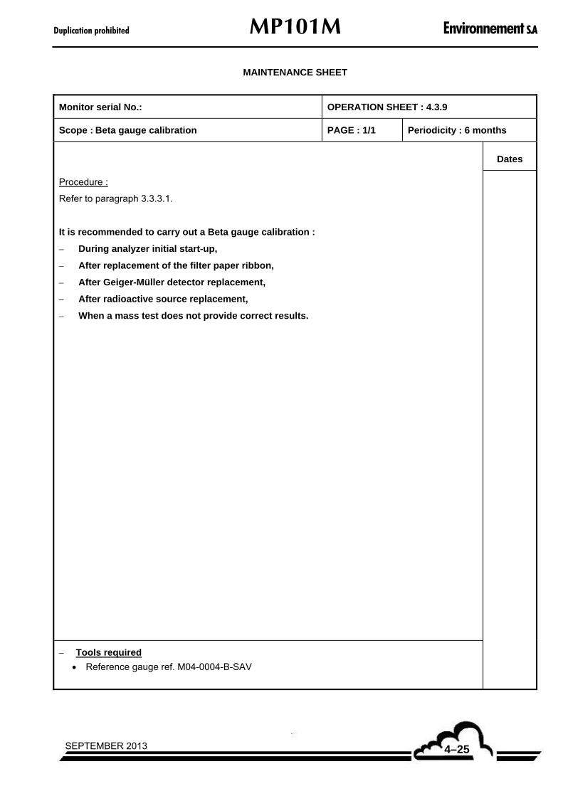
Duplication prohibited MP101M Environnement S.A
4–25SEPTEMBER 2013
MAINTENANCE SHEET
Monitor serial No.: OPERATION SHEET : 4.3.9
Scope : Beta gauge calibration PAGE : 1/1 Periodicity : 6 months
Dates
Procedure :
Refer to paragraph 3.3.3.1.
It is recommended to carry out a Beta gauge calibration :
– During analyzer initial start-up,
– After replacement of the filter paper ribbon,
– After Geiger-Müller detector replacement,
– After radioactive source replacement,
– When a mass test does not provide correct results.
– Tools required
Reference gauge ref. M04-0004-B-SAV
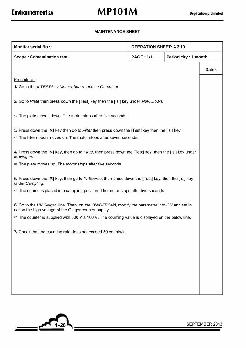
Environnement S.A MP101M Duplication prohibited
SEPTEMBER 20134–26
MAINTENANCE SHEET
Monitor serial No.:: OPERATION SHEET: 4.3.10
Scope : Contamination test PAGE : 1/1 Periodicity : 1 month
Dates
Procedure :
1/ Go to the « TESTS Mother board Inputs / Outputs ».
2/ Go to Plate then press down the [Test] key then the [ s ] key under Mov. Down.
The plate moves down. The motor stops after five seconds.
3/ Press down the [] key then go to Filter then press down the [Test] key then the [ s ] key
The filter ribbon moves on. The motor stops after seven seconds.
4/ Press down the [] key, then go to Plate, then press down the [Test] key, then the [ s ] key under Moving up.
The plate moves up. The motor stops after five seconds.
5/ Press down the [] key, then go to P. Source, then press down the [Test] key, then the [ s ] key under Sampling.
The source is placed into sampling position. The motor stops after five seconds.
6/ Go to the HV Geiger line. Then, on the ON/OFF field, modify the parameter into ON and set in action the high voltage of the Geiger counter supply
The counter is supplied with 600 V 100 V. The counting value is displayed on the below line.
7/ Check that the counting rate does not exceed 30 counts/s.

Duplication prohibited MP101M Environnement S.A
4–27SEPTEMBER 2013
MAINTENANCE SHEET
Monitor serial No.:: OPERATION SHEET: 4.3.11
Scope : Beta gauge check (gauge test, mass test) PAGE : 1/1 Periodicity : 6 months
Dates
1/ Gauge test
Carry out a gauge test by following the instructions described in paragraph 3.3.6.4.
Chose a test number equal to five.
At the end of the five tests, edit the report and check the following values :
– Blank average : check that the value stated in counts/s remains stable compared to the previous test (+/- 200 c/s).
– Measurement : check that the absolute value of the measurement remains lower than 5 µg/cm².
– Standard-deviation : check that the standard deviation remains lower than 5 µg/cm².
If the test fails, repeat the test (no more than three times).
If the detector is too noisy, it is probably necessary to replace it.
If the Blank average value fell down, the source could be damaged. Then, carry out a contamination test.
2/ Mass test
Carry out a mass test by following the instructions described in paragraph 3.3.6.5.
Set test number to 5.
At the end of the five tests, edit the report and check the following values :
– Measurement : check that the measurement value is near to the value indicated on the reference gauge (│Measurement – Reference gauge value│≤ 30 µg/cm²).
– Standard deviation : check that the standard deviation remains lower than 15 µg/cm².
If the test fails, repeat the test.
When the second mass test is not correct yet, carry out a Beta gauge calibration.
– Tools required
Reference gauge : ref. M04-0004-B-SAV

Environnement S.A MP101M Duplication prohibited
SEPTEMBER 20134–28
MAINTENANCE SHEET
Monitor serial No.:: OPERATION SHEET: 4.3.12
Scope : Verification / replacement of temperature and relative humidity sensors.
PAGE : 1/1 Periodicity : 6 months
Dates Procedure :
1/ Go to the « I2C CARD(S) RST board » screen.
2/ Check the values of the atmospheric temperature and relative humidity using reference sensors.
If relative humidity is lower than 60%, check that Head temperature = Atmos. Temperature.
If relative humidity is higher than 60%, check that Head temperature = Atmos. Temperature + 5°C.
3/ If necessary, adjust the A and B linearization coefficients of the three sensors.
4/ In case of replacement of the meteo sensor ( T°C and RH sensors) :
Refer to the calibration report of the relative humidity (RH) sensor provided :
Number sensor
Channel ...........................................
Pente (format xx,xxx)
Slope
S = ..................................... mV / %RH
Offset à zéro (format xx,xxx)
Zero offset
Z = ..................................... V
And on the Relative humidity field of the « I2C CARD(S) RST board » screen, replace the values of the A and B calibration coefficients by :
A = 1 / S
B = - Z x 1000 / S
– Tools required
Reference gauge
– Replacement parts
M04-0045-B-SAV or P10-1317

Duplication prohibited MP101M Environnement S.A
4–29SEPTEMBER 2013
4.4. EQUIPMENT NECESSARY FOR MAINTENANCE
Designation References Quantity
Recommended spare parts MP101M-09-RSP
Wired motor for valve/source/pressure assembly V01-0014-B 1
Socket assembly for T°C and humidity sensor M04-0045-B-SAV 1
GM detector equipped without GM tube M02-5055-A 1
GEIGER-MULLER tube M02-72412-LND 1
Paper roll RF100 ref:10 370 392 M04-370-392 1
Board of RoHS absolute pressure sensor C06-C12-0291-B 1
TR5 4A "RoHS" Time delay fuse S01-FT04_00-A 1
TR5 0.800A "RoHS" Time delay fuse S01-FT00_800-A 1
Flexible sleeve P06-0497-A 1
O-ring oint.:21.95 cord:1.78 Viton G06-021_9-1_7-V 1
Gasket V-RING FPM type VS G12-VS-22-FPM 1
Hybrid gasket G05-AC-184413-B 1

Environnement S.A MP101M Duplication prohibited
SEPTEMBER 20134–30
Other spare parts :
Designation References Quantity
Mains cable lg.:2,50 black "RoHS" D02-CS-002-A 1
Fuses for 230V/50Hz :
Time delay fuse D1TD /5A o5x20 S01-TT05_00-A 2
Fuses for 115V/60Hz :
Time delay fuse D1TD /3,15A o5x20 S01-TT03_15-A 2
Front face :
MP101M switch cable D01-1171-A 1
"RoHS" LCD display I03-0002-A 1
DNP ARM7 V2 board, MP101 version C03-P1-0383-D 1
RST sensor :
Socket assembly for T°C and humidity sensor M04-0045-B-SAV 1
Beta gauge :
Beta source + counter assembly M01-0084-A 1
Equipped GM detector M02-5049-B 1
GEIGER-MULLER Tube M02-72412-LND 1
MP101 reference gauge M04-0004-B-SAV 1
Upper sampling channel F09-5003-B-SAV 1
Wired motor for valve/source/pressure assembly V01-0014-B 1
Temperature sensor of MP101M wired source D01-1164-A 1
Paper moving on :
Wired motor for moving on paper (230V/50Hz) V01-0015-A 1
Wired motor for moving on paper (115V/60Hz) V01-0016-A 1
Notched belt ref.6T5/305 G05-BM-6T5-B 1
Control flow rate part :
MP101 flow rate control assembly F02-0151-A 1
MP101M Powered valve F01-0115-A 1
Board of RoHS absolute pressure sensor C06-C12-0291-A 1
Fitting for reference flow meter :
Fitting (PM162M FLOW RATE TEST) P02-1571-1 1
O ring oint.:15 corde:3 Silicon (for fitting P02-1571-1) G06-015_0-3_0-S 1
Various
MP101 wired fan V03-0011-B 1
Gasket V-RING FPM type VS G12-VS-22-FPM 1
O ring oint.:27 cord:2 Viton G06-027_0-2_0-V 1
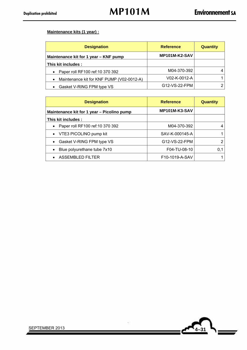
Duplication prohibited MP101M Environnement S.A
4–31SEPTEMBER 2013
Maintenance kits (1 year) :
Designation Reference Quantity
Maintenance kit for 1 year – KNF pump MP101M-K2-SAV
This kit includes :
Paper roll RF100 ref:10 370 392 M04-370-392 4
Maintenance kit for KNF PUMP (V02-0012-A) V02-K-0012-A 1
Gasket V-RING FPM type VS G12-VS-22-FPM 2
Designation Reference Quantity
Maintenance kit for 1 year – Picolino pump MP101M-K3-SAV
This kit includes :
Paper roll RF100 ref:10 370 392 M04-370-392 4
VTE3 PICOLINO pump kit SAV-K-000145-A 1
Gasket V-RING FPM type VS G12-VS-22-FPM 2
Blue polyurethane tube 7x10 F04-TU-08-10 0,1
ASSEMBLED FILTER F10-1019-A-SAV 1

Environnement S.A MP101M Duplication prohibited
SEPTEMBER 20134–32
Page intentionally left blank

Duplication prohibited MP101M Environnement S.A
5–1SEPTEMBER 2013
CHAPTER 5
CORRECTIVE MAINTENANCE
5.1. LIST OF FAULTS AND CORRECTIVE ACTIONS 5–4
5.2. MODULE BOARD OF MP101M 5–8
5.3. GENERAL CONNECTION DIAGRAM 5–9
Table 5–1 – List of faults and correctives actions 5–4 Table 5–2 – Configuration of Module board 5–8
Environnement S.A MP101M Duplication prohibited
SEPTEMBER 20135–2
Page intentionally left blank
Duplication prohibited MP101M Environnement S.A
5–3SEPTEMBER 2013
5. CORRECTIVE MAINTENANCE
Corrective maintenance of the monitor should only be performed by qualified personnel using the information provided in this document.
The monitor automatically and continuously self-tests its main components. Any malfunction detected is indicated by a plain-language message on the display and a buzzer.
Table 5.1 summarizes the main faults indicated by the unit with corresponding possible corrective actions.
WARNING – Refer to chapter 0, safety guidelines section, pages 0-10 to 0-18.

Environnement S.A MP101M Duplication prohibited
SEPTEMBER 20135–4
5.1. LIST OF FAULTS AND CORRECTIVE ACTIONS
Table 5–1 – List of faults and correctives actions
DISPLAY CAUSE POSSIBLE ACTIONS
0 V
– The ground potential is lower than - 0,05 V or higher than 0,05 V.
– Connect a voltmeter between the Pt16 test point and a screw used to settle the board on the drawer bottom : check the measured value.
– Check correct operation of the + 5 V.
+5 V
– The power supply delivers a voltage lower than 4,8 V or higher than 5,2 V.
– Connect a voltmeter between the Pt16 test point (ground) and the Pt12 (+ 5V) test point: check the measured value.
+15 V
– The power supply delivers a voltage lower than 14,50 V or higher than 15,50 V.
– Connect a voltmeter between the Pt16 (ground) test point and the Pt13 (+ 15V) test point : check the measured value.
-15 V
– The power supply delivers a voltage lower than - 15,50 V or higher than - 14,50 V.
– Connect a voltmeter between the Pt16 (ground) test point and the Pt14 (- 15V) test point : check the measured value.
Temperature
– At least, one of the internal T°C temperature or filter T°C temperature exceeds the acceptable intervals.
– The analyzer does not work under the normal operating conditions.
– Check status of the temperature sensors and change them if they are out of order.
Pressure
– At least, one of the upstream pressure, or downstream pressure or atmospheric pressure exceeds the acceptable interval.
– In the screen « CALIBRATION Pressures », check the A and B linearization coefficients for the three sensors.
– The pump being off, check that the three pressures are quite equal.
– Change the pressure sensor(s) if they are out of order.
Gauge
– The Geiger-Müller tube detector provides a result lower than 1000 counts/s or higher than 8500 counts/s.
– Check correct positioning of the filter ribbon.
– Check the power supply voltage (600 V).
– Check the positioning of the source in front of paper. If the source is not correctly positioned, check correct operation of the positioning motor.
– If the motor does not work : check the + 15V and - 15V voltages.

Duplication prohibited MP101M Environnement S.A
5–5SEPTEMBER 2013
DISPLAY CAUSE POSSIBLE ACTIONS
Threshold D.
– The periodic or cyclic measurement exceeds the superior allowed value (1000 µg/m3 or 1000 mg/m3).
– Change the measurement units: replace µg/m3 by mg/m3 in the « CONFIGURATION Offsets and units » screen.
– Check the source positioning in front of the paper. If it is not correctly positioned, check correct operation of the positioning motor.
– If the motor does not work, check the + 15V and - 15V voltages.
Clogging
– The system remained more than 360 s (6 min) running in regulation valve control mode and
: 1013
7501
APP
.
– Check the pressures: Upstream pressure, Downstream pressure, Atmospheric pressure.
– Check the correct operation of the valve motor control (refer to the screen « TESTS Mother board Inlets/outlets »).
– Check the valve motor.
– Check the valve.
– Check the fluid circuit.
Flow rate – The flow rate exceeds the allowed interval centered around the 1 m3/h control.
– Check the correct operation of motor valve control (refer to the screen « TESTS Mother board Inputs/Outputs »).
– Check the valve motor.
– Check the valve.
– Test for leaks in the fluid circuit.
R.A.N. counting – The analyzer detects an abnormally high rate of natural radioactivity.
– Inform the appropriate authorities as soon as possible.
Paper torn up
– Counting value provided by the Geiger-Müller > 8500 counts/s.
– Check the position of the filter paper ribbon. Reposition it again.
– Carry out a contamination test.
– Check the source positioning in front of the paper. If the source is not correctly positioned, check correct operation of the positioning motor. If the motor does not work: check the + 15V and - 15V voltages.
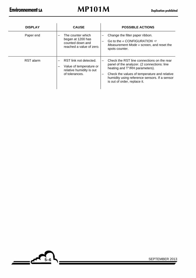
Environnement S.A MP101M Duplication prohibited
SEPTEMBER 20135–6
DISPLAY CAUSE POSSIBLE ACTIONS
Paper end
– The counter which began at 1200 has counted down and reached a value of zero.
– Change the filter paper ribbon.
– Go to the « CONFIGURATION Measurement Mode » screen, and reset the spots counter.
RST alarm – RST link not detected.
– Value of temperature or relative humidity is out of tolerances.
– Check the RST line connections on the rear panel of the analyzer. (2 connections: line heating and T°/RH parameters).
– Check the values of temperature and relative humidity using reference sensors. If a sensor is out of order, replace it.

Duplication prohibited MP101M Environnement S.A
5–7SEPTEMBER 2013
Page intentionally left blank

Environnement S.A MP101M Duplication prohibited
SEPTEMBER 20135–8
5.2. MODULE BOARD OF MP101M
Table 5–2 – Configuration of Module board
Jumper mark Symbols Function Symbols Function
SW1
RS323
RS422
SW2
RS232
RS422
SW3
RS232
RS422
SW4
HT Geiger reading
ST2 600 V HT Geiger
ST7 Pic RST address
ST8 Pic RST address


Environnement S.A MP101M Duplication prohibited
SEPTEMBER 20135–10
Page intentionally left blank

Duplication prohibited MP101M Environnement S.A
SEPTEMBER 2013 6–1
6
APPENDICES
Appendix 1 : ESTEL BOARD
Appendix 2 : DNP-ARM7 BOARD

Environnement S.A MP101M Duplication prohibited
SEPTEMBER 20136–2
Page intentionally left blank

111 bd Robespierre, 78300 POISSY - -TEL. 33(0)-1.39.22.38.00 – FAX 33(0)-1.39 65.38.08 http://www.environnement-sa.com
ESTEL Board
INPUTS / OUTPUTS BOARD
OPTION OF 2M ANALYZERS
- June 2009 -
WARNING
Information contained in this document is likely to be modified without notice. The designer reserves the right to modify the equipment without revising this document.
Therefore, information in this document does not represent a commitment on behalf of ENVIRONNEMENT S.A.
ENVIRONNEMENT S.A. all rights reserved.

Environnement S.A ESTEL Board Duplication prohibited
JUNE 20092
ESTEL BOARD
1.1 FUNCTION AND USE 3
1.2 TECHNICAL CHARACTERISTICS 3
1.3 CONFIGURATION 4
1.4 PROGRAMMING 8
1.4.1 ESTEL CARD(S) Analog output 9
1.4.2 ESTEL CARD(S) Analog input 11
1.4.3 ESTEL CARD(S) Relay 12
1.4.4 ESTEL CARD(S) Remote controls 13
1.5 INSTALLATION AND REPLACEMENT OF ESTEL BOARD 14
1.5.1 Switch off the analyzer 14
1.5.2 Unplug the main cable 14
1.5.3 Take off the cover 14
1.5.4 Dismount ESTEL board 15
1.5.5 Unrivet the back plate of rear panel of analyzer 15
1.5.6 Install board inside analyzer 16
1.6 EXTERNAL CONNECTION OPTIONS 17
Figure 1 – ESTEL board – index A 5 Figure 2 – ESTEL board – index B 6 Figure 3 – External connection option P10-1337-A 18 Figure 4 – External connection option plus four insulated outputs P10-1338-A 18 Table 1 – Configuration of ESTEL board – index A 5 Table 2 – Configuration of ESTEL board – index B 6
Update: Pages Update Pages Update Pages Update
1 05-2004 9 06-2009 17 06-2009
2 05-2004 10 06-2009 18 06-2009
3 05-2004 11 06-2009
4 05-2004 12 06-2009
5 05-2004 13 06-2009
6 05-2004 14 06-2009
7 05-2004 15 06-2009
8 06-2009 16 06-2009

Duplication prohibited ESTEL Board Environnement S.A
JUNE 2009 3
1. ESTEL BOARD
The ESTEL board is a universal logic board of analog inputs/outputs for the 2M series analyzers. This board is optional, and it is possible to install two ESTEL boards in an analyzer.
1.1 FUNCTION AND USE
The ESTEL board has four functions:
Four analog inputs
Four analog outputs
Six relays
Four remote controls
The ESTEL board enables dialog with the measurement module and assumes its input/output functions. It allows remote control and/or remote signalling of certain status such as measurement, zero, calibration, and alarm.
The analog inputs are used to connect independent monitors in order to follow up, for example, meteorological data.
The analog outputs allow numeric parameters (e.g., gas concentration to be analyzed, MUX channels) to be sent to analog-independent peripherals in order, for example, to store and process several months of data.
The analyzer can work as an autonomous unit of analysis when equipped with an ESTEL board.
1.2 TECHNICAL CHARACTERISTICS
Management by specialized microcontroller:
Four analog inputs of 12 bits, 0–2,5 volts full scale
Four non-insulated analog outputs, configurable into 0–1 volts, 0–10 volts, 0–20 mA, and 4–20 mA (maximum load of 1000 Ohm)
Four insulated optocoupler logic inputs
Six potentially free contacts for remote signalling
One power supply of 8–24 volts
i2C communication visualization using a LED
Electrical connections:
Four-point connector for link with module boards of 2M series
Inputs/outputs centralized on one female connector SUB D37 points located on the rear panel of the analyzer.
Option of external connection (see section 1.6)
Voltage and current on relays:
Maximum voltage by relay contact: 50 volts
Maximum current by relay contact: 1 ampere at 24 V DC (resistive load)
Remote control:
By dry contact (see section 1.3)
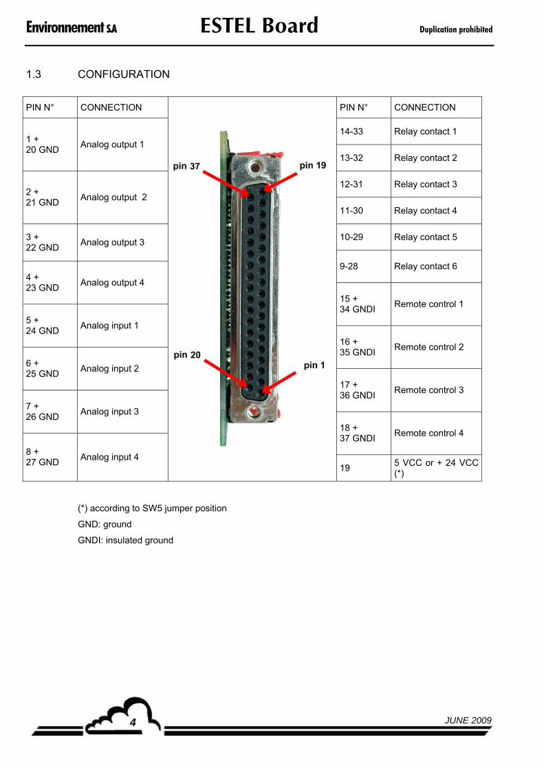
Environnement S.A ESTEL Board Duplication prohibited
JUNE 20094
1.3 CONFIGURATION
PIN N° CONNECTION PIN N° CONNECTION
14-33 Relay contact 1 1 + 20 GND
Analog output 1
13-32 Relay contact 2
12-31 Relay contact 3 2 + 21 GND
Analog output 2
11-30 Relay contact 4
10-29 Relay contact 5 3 + 22 GND
Analog output 3
9-28 Relay contact 6 4 + 23 GND
Analog output 4
15 + 34 GNDI
Remote control 1
5 + 24 GND
Analog input 1
16 + 35 GNDI
Remote control 2
6 + 25 GND
Analog input 2
17 + 36 GNDI
Remote control 3
7 + 26 GND
Analog input 3
18 + 37 GNDI
Remote control 4
8 + 27 GND
Analog input 4
19 5 VCC or + 24 VCC (*)
(*) according to SW5 jumper position
GND: ground
GNDI: insulated ground

Duplication prohibited ESTEL Board Environnement S.A
JUNE 2009 5
Table 1 – Configuration of ESTEL board – index A
Jumper marks
Symbols Nature of operations
ESTEL selection, board N° 1
ESTEL selection, board N° 2
ESTEL selection, board N° 3
ST1, ST2, ST8
ESTEL selection, board N° 4
0 V to ground (default) ST3
Floating 0 V
0–1 V, idem for the 4 DAC
0–10 V, idem for the 4 DAC
0–20 mA, idem for the 4 DAC
DAC1 DAC2 DAC3 DAC4
4–20 mA, idem for the 4 DAC
P1, P2, P3, P4
4 mA adjustment in 4–20 mA mode
ST : strap
P : potentiometer
DAC : digital analog converter
SW : switch
Figure 1 – ESTEL board– index A
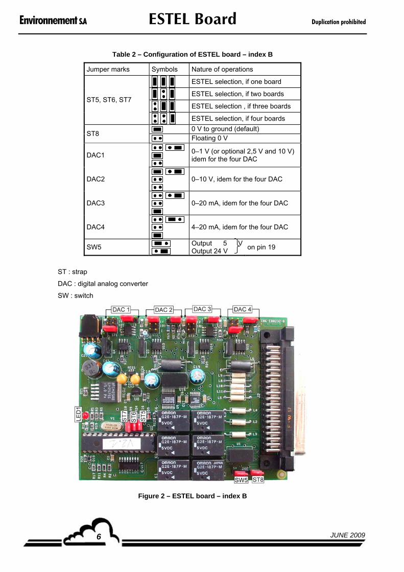
Environnement S.A ESTEL Board Duplication prohibited
JUNE 20096
Table 2 – Configuration of ESTEL board – index B
Jumper marks Symbols Nature of operations
ESTEL selection, if one board
ESTEL selection, if two boards
ESTEL selection , if three boards ST5, ST6, ST7
ESTEL selection, if four boards
0 V to ground (default) ST8
Floating 0 V
DAC1
0–1 V (or optional 2,5 V and 10 V) idem for the four DAC
DAC2
0–10 V, idem for the four DAC
DAC3
0–20 mA, idem for the four DAC
DAC4
4–20 mA, idem for the four DAC
SW5
Output 5 VOutput 24 V
on pin 19
ST : strap
DAC : digital analog converter
SW : switch
Figure 2 – ESTEL board – index B
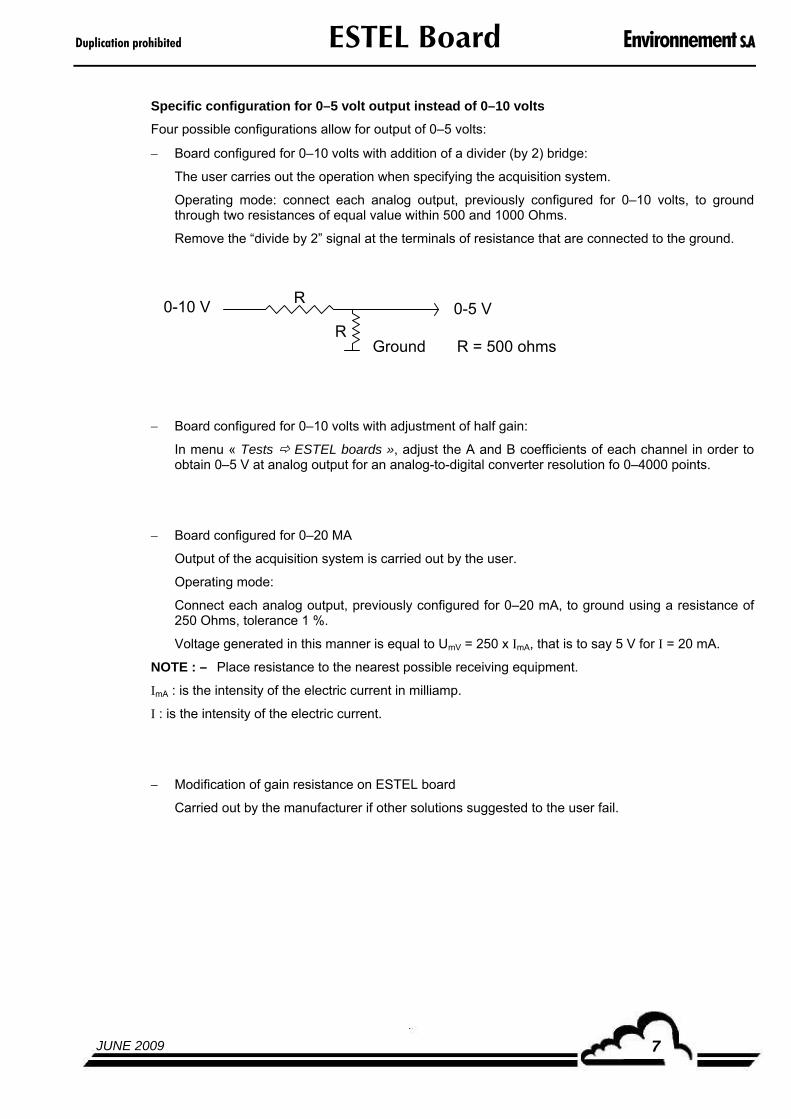
Duplication prohibited ESTEL Board Environnement S.A
JUNE 2009 7
Specific configuration for 0–5 volt output instead of 0–10 volts
Four possible configurations allow for output of 0–5 volts:
Board configured for 0–10 volts with addition of a divider (by 2) bridge:
The user carries out the operation when specifying the acquisition system.
Operating mode: connect each analog output, previously configured for 0–10 volts, to ground through two resistances of equal value within 500 and 1000 Ohms.
Remove the “divide by 2” signal at the terminals of resistance that are connected to the ground.
0-10 V
GroundR
R0-5 V
R = 500 ohms
Board configured for 0–10 volts with adjustment of half gain:
In menu « Tests ESTEL boards », adjust the A and B coefficients of each channel in order to obtain 0–5 V at analog output for an analog-to-digital converter resolution fo 0–4000 points.
Board configured for 0–20 MA
Output of the acquisition system is carried out by the user.
Operating mode:
Connect each analog output, previously configured for 0–20 mA, to ground using a resistance of 250 Ohms, tolerance 1 %.
Voltage generated in this manner is equal to UmV = 250 x ImA, that is to say 5 V for I = 20 mA.
NOTE : – Place resistance to the nearest possible receiving equipment.
ImA : is the intensity of the electric current in milliamp.
I : is the intensity of the electric current.
Modification of gain resistance on ESTEL board
Carried out by the manufacturer if other solutions suggested to the user fail.
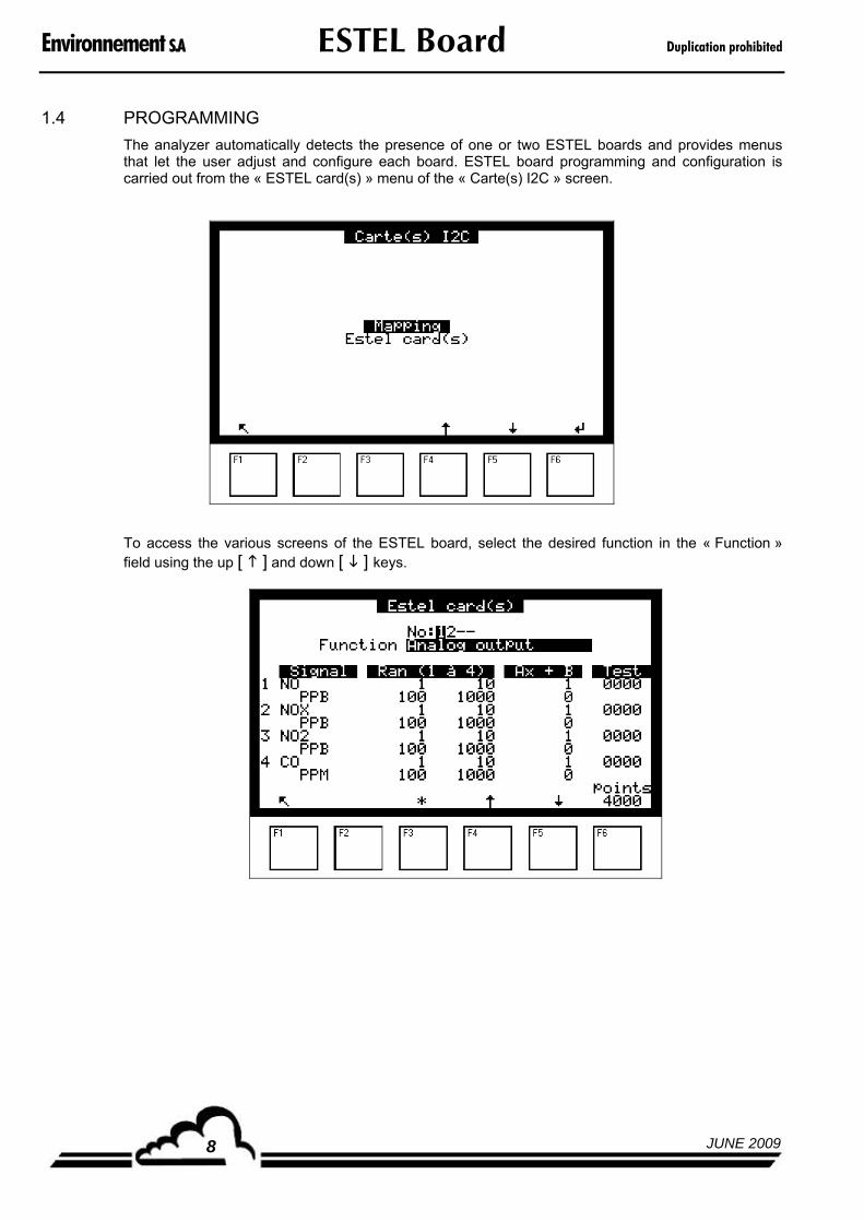
Environnement S.A ESTEL Board Duplication prohibited
JUNE 20098
1.4 PROGRAMMING
The analyzer automatically detects the presence of one or two ESTEL boards and provides menus that let the user adjust and configure each board. ESTEL board programming and configuration is carried out from the « ESTEL card(s) » menu of the « Carte(s) I2C » screen.
To access the various screens of the ESTEL board, select the desired function in the « Function » field using the up [ ] and down [ ] keys.

Duplication prohibited ESTEL Board Environnement S.A
JUNE 2009 9
1.4.1 ESTEL CARD(S) Analog output
This screen lets the user assign parameters to the analog outputs for the ESTEL board whose number is highlighted in the « No » field. These parameters are as follows:
Concentration of analyzed gases
Auxiliary channels (multiplexer)
Analog inputs
Analog outputs on an ESTEL board can be configured for 0–1 volt, 0–10 volts, 0–20 mA, and 4–20 mA. These four ranges correspond to the full scale of the analog output, and the units are those of the parameters displayed in the « Signal » column. When the signal value is higher than the full scale of the current range, the analyzer switches to the next higher range. It switches back to the lower range when measurement again falls below 85%. When the user assigns several measurement ranges to only one analog output, the metrological resolution can be changed as shown below. To avoid range switching, the user must assign the same value to the four ranges of the parameter that will be sent as analog output.
1 2 3 40
1V
MEASUREMENT RANGES (PPM)
OU
TP
UT
SIG
NA
L
10 100 1000 10000
The Ax+B calibration curve is used to adjust the mV signal of the selected analog output.
The « Test » column is used to test the four analog outputs and to adjust the number of points.
For the range 1:
0 point (lower scale of output) 0 volt obtained at output.
4000 points (higher scale of output) 1 volt obtained at output.
[4000 points] key applies the full scale to all analog outputs.

Environnement S.A ESTEL Board Duplication prohibited
JUNE 200910
1.4.2 ESTEL CARD(S) Analog input
Each ESTEL board has four analog inputs: this screen is used to program the following characteristics of these analog inputs:
« Name » fields are used to enter a name of up to eight alphanumeric characters.
« Unit » fields are used to select the unit from the toggle menu.: none, ppt, ppb, ppm, μg/m3, mg/m3, gr/m3, μg/Nm3, mg/Nm3, gr/Nm3, μg/Sm3, mg/Sm3, gr/Sm3, %, μgr, mgr, gr, mV, U, °C, °K, hPa, mb, b,l, Nl, Sl, m3, l/min, NI/min, Sl/min, m3/h, Nm3/h, Sm3/h, m/s ou km/h.
The « Ax + B » fields are used to adjust the calibration curve of each parameter.

Duplication prohibited ESTEL Board Environnement S.A
JUNE 2009 11
1.4.3 ESTEL CARD(S) Relay
The « Relays » fields are used to set relays according to the following conditions:
Disable Relay not assigned
General alarm Any operating fault triggers the relay
Range over range Scale 2 over range triggers the relay
Flow rate Abnormal flow rate triggers the relays
Temperature Abnormal temperature in the analyzer triggers the relay
Pressure Barometric pressure in chamber
Zero Air On Zero, relay is triggered
Span On Span, relay is triggered
Zero-Ref On Zero-Ref, relay is triggered
Auto-Span On Auto-Span, relay is triggered
Warm-up On Warm-up, relay is triggered
Stop mode In Stop mode, relay is triggered
Alarm control Control detection during threshold over range, relay is triggered.
Alarm or control Relay triggered
Module alarm Alarm detected on module, relay triggered
Measure Relay triggered
Maintenance In Maintenance mode, relay is triggered
« Type » fields are used to control (N.C.) or not (N.O.) the relays when alarms are OFF.
« Test » fields are used to manually control these relays.
N.C. : normally closed
N.O. : normally open

Environnement S.A ESTEL Board Duplication prohibited
JUNE 200912
1.4.4 ESTEL CARD(S) Remote controls
This screen displays the assignment of remote control inlets. The available assignment choices are « Inactive », « Stop mode », « Zero Ref. », « Zero », « Span », « Auto span ».
The «Test » column is used to display the value read at the remote control inlet for the selected assignment.

Duplication prohibited ESTEL Board Environnement S.A
JUNE 2009 13
1.5 INSTALLATION AND REPLACEMENT OF ESTEL BOARD
User’s safety recommendation : Switch off the analyzer and unplug the main cable before any maintenance work of the analyzer.
Analyzer’s safety recommendation: Respect the connection of ESTEL board / Module board at J20 when reassembling.
Use the steps illustrated below for installation or replacement of the ESTEL board.
1.5.1 Switch off analyzer. 1.5.2 Unplug main cable.
1.5.3 Take off cover.
(2) Unscrew screws on lateral sides.
(1) Unscrew screws on rear panel of analyzer.
(3) Lift up cover. (4) Remove cover by pulling it backwards.

Environnement S.A ESTEL Board Duplication prohibited
JUNE 200914
If the analyzer is already equipped with an ESTEL board, follow step 1.5.4.
If the analyzer is not equipped with ESTEL board, follow step 1.5.5.
1.5.4 Dismount ESTEL board.
(1) Module board
(2) ESTEL board
(3) J20 connector on module board
(4)Connecting cable between ESTEL board and module board
(5)Fixing screw of ESTEL board on rear panel of analyzer
Disconnect connecting cable between ESTEL board (4) and module board (3).
Unscrew fixing screws (5) of ESTEL board on rear panel of analyzer.
Remove ESTEL board.
Configure jumpers of new board, with the functionality described in Table 1 or Table 2 in section 1.3 CONFIGURATION.
Reassemble the board.
1.5.5 Unrivet the back plate (6) of rear panel of analyzer
(7)
Then install the new plate (7) delivered with the board at the same place.
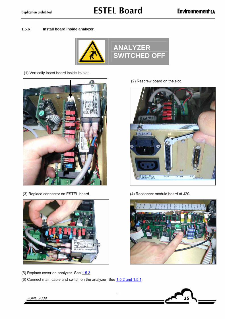
Duplication prohibited ESTEL Board Environnement S.A
JUNE 2009 15
1.5.6 Install board inside analyzer.
ANALYZER SWITCHED OFF
(1) Vertically insert board inside its slot.
(2) Rescrew board on the slot.
(3) Replace connector on ESTEL board. (4) Reconnect module board at J20.
(5) Replace cover on analyzer. See 1.5.3 .
(6) Connect main cable and switch on the analyzer. See 1.5.2 and 1.5.1.

Environnement S.A ESTEL Board Duplication prohibited
JUNE 200916
1.6 EXTERNAL CONNECTION OPTIONS
Five different ESTEL external connection options are available:
DESIGNATION REFERENCE MARK
External ESTEL connection P10-1337-A Figure 3
Cable D02-INF-37-37M-M-A (1)
Tie-point block interface board C10-0012-A (2)
DIN track G13-IB-18066 (3)
DESIGNATION REFERENCE MARK
External ESTEL connection + four insulated outputs P10-1338-A Figure 4
Cable D02-INF-37-37M-M-A (1)
Tie-point block interface board C10-0012-A (2)
Symmetrical DIN track limit stop G13-IB-18066 D03-103-002-26
(3)
Two-way galvanic insulator I11-Jk2000-2 (4)
DESIGNATION REFERENCE MARK
External ESTEL connection + one insulated output P10-1350-A Figure 4
Cable D02-INF-37-37M-M-A (1)
Tie-point block interface board C10-0012-A (2)
Symmetrical DIN track limit stop G13-IB-18066 D03-103-002-26
(3)
One-way galvanic insulator I11-Jk2000-1 (4)
DESIGNATION REFERENCE MARK
External ESTEL connection + two insulated outputs P10-1351-A Figure 4
Cable D02-INF-37-37M-M-A (1)
Tie-point block interface board C10-0012-A (2)
Symmetrical DIN track Limit stop
G13-IB-18066 D03-103-002-26
(3)
Two-way galvanic insulator I11-Jk2000-2 (4)
DESIGNATION REFERENCE MARK
External ESTEL connection + three insulated outputs P10-1352-A Figure 4
Cable D02-INF-37-37M-M-A (1)
Tie-point block interface board C10-0012-A (2)
Symmetrical DIN track Limit stop
G13-IB-18066 D03-103-002-26
(3)
Two-way galvanic insulator One-way galvanic insulator
I11-Jk2000-2 I11-JK2000-1
(4)

Duplication prohibited ESTEL Board Environnement S.A
JUNE 2009 17
Figure 3 – External connection option
Figure 4 – External connection option + four insulated outputs

Environnement S.A ESTEL Board Duplication prohibited
JUNE 200918
Page intentionally left blank
111 bd Robespierre, 78300 POISSY - -TEL. 33(0)-1.39.22.38.00 – FAX 33(0)-1.39 65.38.08 http://www.environnement-sa.com
DNP-ARM7 board
EMBEDDED PROCESSOR UNDER UCLINUX OPERATING SYSTEM
- NOVEMBER 2009 -
WARNING
Information contained in this document is likely to be modified without notice. The designer reserves the right to modify the equipment without revising this document.
Therefore, information in this document does not represent a commitment on behalf of ENVIRONNEMENT S.A.
ENVIRONNEMENT S.A. all rights reserved.
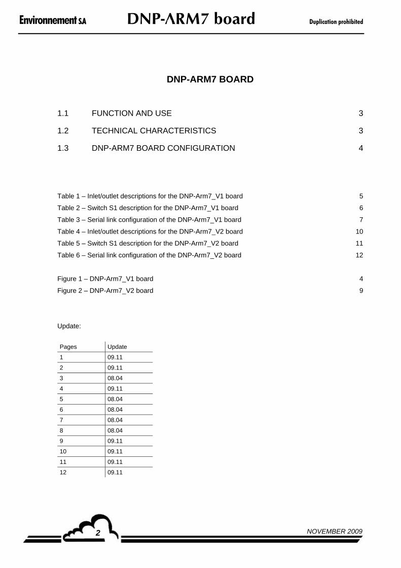
Environnement S.A DNP-ARM7 board Duplication prohibited
NOVEMBER 20092
DNP-ARM7 BOARD
1.1 FUNCTION AND USE 3
1.2 TECHNICAL CHARACTERISTICS 3
1.3 DNP-ARM7 BOARD CONFIGURATION 4
Table 1 – Inlet/outlet descriptions for the DNP-Arm7_V1 board 5
Table 2 – Switch S1 description for the DNP-Arm7_V1 board 6
Table 3 – Serial link configuration of the DNP-Arm7_V1 board 7
Table 4 – Inlet/outlet descriptions for the DNP-Arm7_V2 board 10
Table 5 – Switch S1 description for the DNP-Arm7_V2 board 11
Table 6 – Serial link configuration of the DNP-Arm7_V2 board 12
Figure 1 – DNP-Arm7_V1 board 4
Figure 2 – DNP-Arm7_V2 board 9
Update:
Pages Update
1 09.11
2 09.11
3 08.04
4 09.11
5 08.04
6 08.04
7 08.04
8 08.04
9 09.11
10 09.11
11 09.11
12 09.11
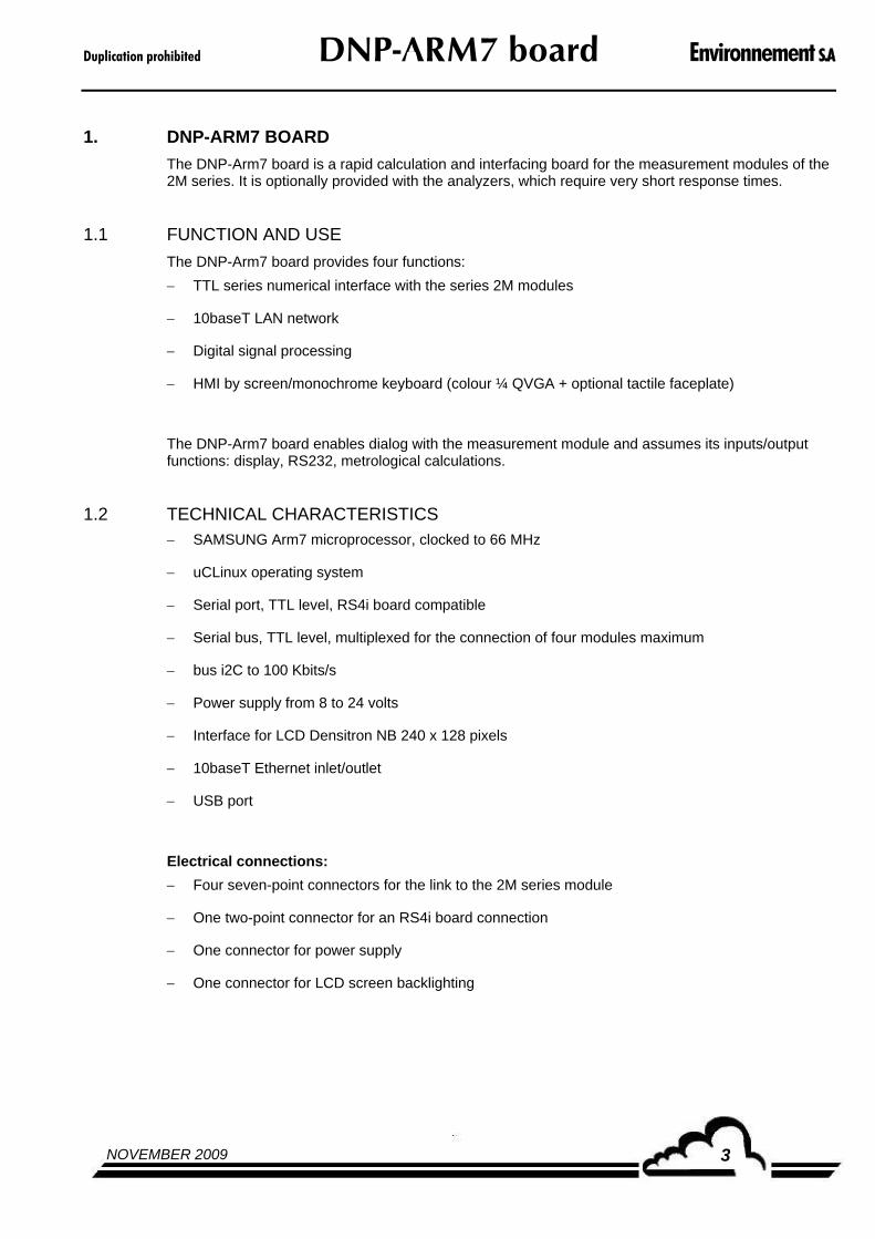
Duplication prohibited DNP-ARM7 board Environnement S.A
NOVEMBER 2009 3
1. DNP-ARM7 BOARD
The DNP-Arm7 board is a rapid calculation and interfacing board for the measurement modules of the 2M series. It is optionally provided with the analyzers, which require very short response times.
1.1 FUNCTION AND USE
The DNP-Arm7 board provides four functions:
TTL series numerical interface with the series 2M modules
10baseT LAN network
Digital signal processing
HMI by screen/monochrome keyboard (colour ¼ QVGA + optional tactile faceplate)
The DNP-Arm7 board enables dialog with the measurement module and assumes its inputs/output functions: display, RS232, metrological calculations.
1.2 TECHNICAL CHARACTERISTICS SAMSUNG Arm7 microprocessor, clocked to 66 MHz
uCLinux operating system
Serial port, TTL level, RS4i board compatible
Serial bus, TTL level, multiplexed for the connection of four modules maximum
bus i2C to 100 Kbits/s
Power supply from 8 to 24 volts
Interface for LCD Densitron NB 240 x 128 pixels
10baseT Ethernet inlet/outlet
USB port
Electrical connections:
Four seven-point connectors for the link to the 2M series module
One two-point connector for an RS4i board connection
One connector for power supply
One connector for LCD screen backlighting

Environnement S.A DNP-ARM7 board Duplication prohibited
NOVEMBER 20094
1.3 DNP-ARM7 BOARD CONFIGURATION
Upper guiding-mark of the board
Figure 1 – DNP-Arm7_V1 board
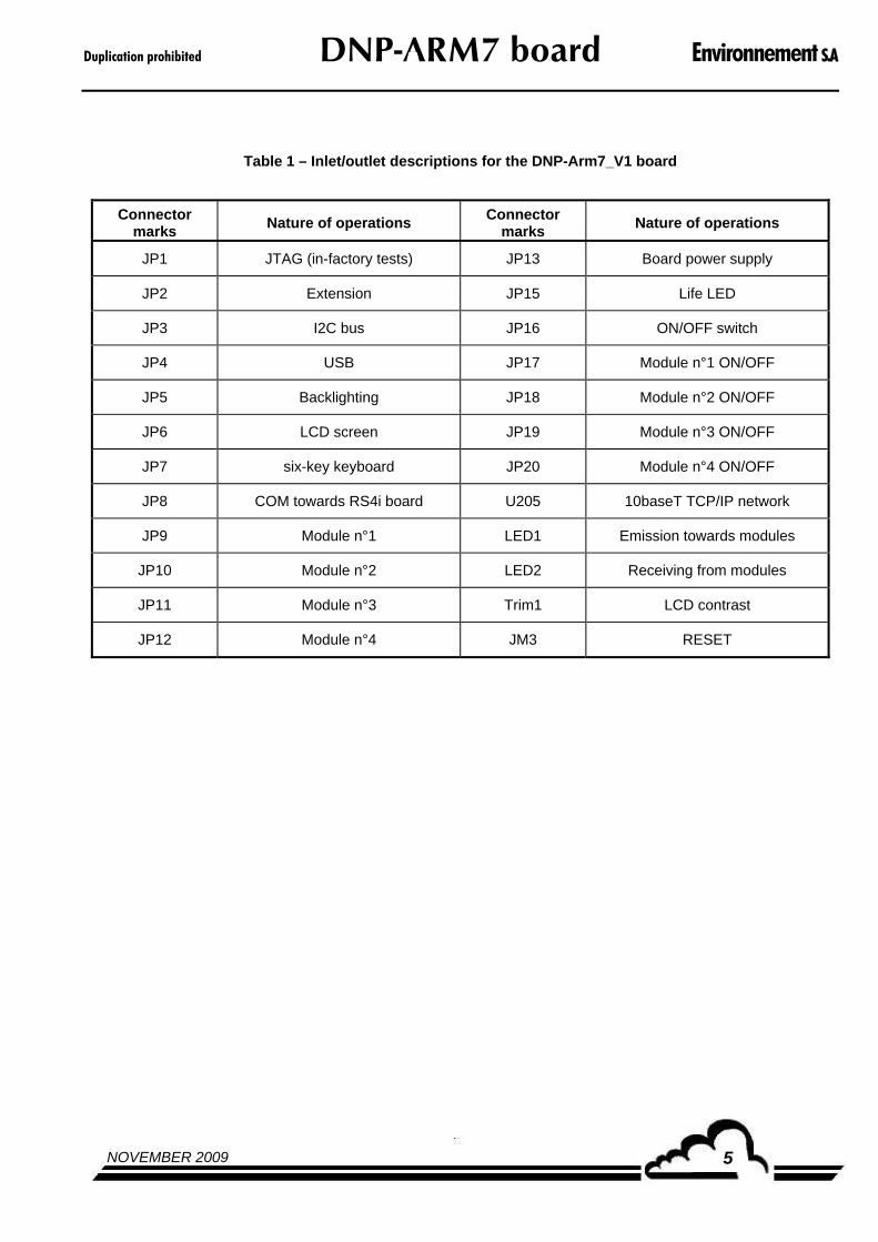
Duplication prohibited DNP-ARM7 board Environnement S.A
NOVEMBER 2009 5
Table 1 – Inlet/outlet descriptions for the DNP-Arm7_V1 board
Connector marks
Nature of operations Connector
marks Nature of operations
JP1 JTAG (in-factory tests) JP13 Board power supply
JP2 Extension JP15 Life LED
JP3 I2C bus JP16 ON/OFF switch
JP4 USB JP17 Module n°1 ON/OFF
JP5 Backlighting JP18 Module n°2 ON/OFF
JP6 LCD screen JP19 Module n°3 ON/OFF
JP7 six-key keyboard JP20 Module n°4 ON/OFF
JP8 COM towards RS4i board U205 10baseT TCP/IP network
JP9 Module n°1 LED1 Emission towards modules
JP10 Module n°2 LED2 Receiving from modules
JP11 Module n°3 Trim1 LCD contrast
JP12 Module n°4 JM3 RESET

Environnement S.A DNP-ARM7 board Duplication prohibited
NOVEMBER 20096
Table 2 – Switch S1 description for the DNP-Arm7_V1 board
DIP Switch Symbols Nature of operations By default
down position
ON battery
S1-8
up position OFF battery *
down position
ON AutoStart
S1-7
up position OFF AutoStart *
down position
IP Address = 192.101.0.1
S1-6
up position Programmed IP Address *
down position
Inactive WatchDog
S1-5
up position Active WatchDog *
down position
Software start-up in service mode
address = 192.168.0.30
S1-4
up position Application starting-up *
down position
Program update without LCD screen (AutoLoad ON )
S1-3
up position Program update without LCD screen ( AutoLoad OFF ) *
down position
STARTUP program execution at power-on ON
S1-2
up position STARTUP program execution at power-on OFF *
down position
Maintenance ON
S1-1
up position Maintenance OFF *
NOTE : S1-3 depends on S1-2 ON
S1-4 has priority over S1-6

Duplication prohibited DNP-ARM7 board Environnement S.A
NOVEMBER 2009 7
Table 3 – Serial link configuration of the DNP-Arm7_V1 board
Jumper marks
Symbols Nature of operations By default
up position
COM2-TX towards RS4i
JM1
down position COM2-TX towards module *
up position
COM2-RX towards RS4i
JM2
down position COM2-RX towards module *

Environnement S.A DNP-ARM7 board Duplication prohibited
NOVEMBER 20098
Page intentionally left blank
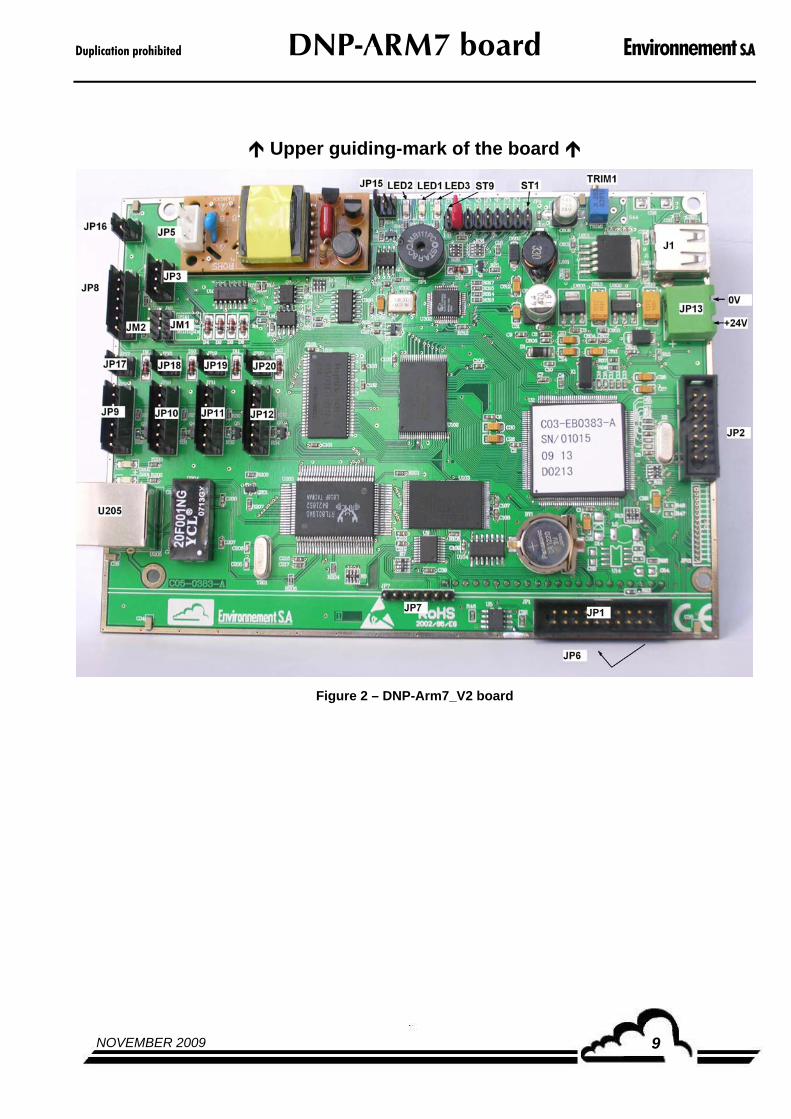
Duplication prohibited DNP-ARM7 board Environnement S.A
NOVEMBER 2009 9
Upper guiding-mark of the board
Figure 2 – DNP-Arm7_V2 board

Environnement S.A DNP-ARM7 board Duplication prohibited
NOVEMBER 200910
Table 4 - Inlet/outlet descriptions for the DNP-Arm7_V2 board
Connector marks
Nature of operations Connector
marks Nature of operations
JP1 JTAG (in-factory tests) JP13 Board power supply
JP2 Extension JP15 Life LED
JP3 I2C bus JP16 ON/OFF switch
J1 USB JP17 Module n°1 ON/OFF
JP5 Backlighting JP18 Module n°2 ON/OFF
JP6 LCD screen JP19 Module n°3 ON/OFF
JP7 six-key keyboard JP20 Module n°4 ON/OFF
JP8 COM towards RS4i board U205 10baseT TCP/IP network
JP9 Module n°1 LED1 Emission towards modules
JP10 Module n°2 LED2 Receiving from modules
JP11 Module n°3 LED3 POWER ON
JP12 Module n°4 Trim1 LCD contrast

Duplication prohibited DNP-ARM7 board Environnement S.A
NOVEMBER 2009 11
Table 5 – Switch S1 description for the DNP-Arm7_V2 board
DIP Switch Symbols Nature of operations By default
OFF Reset * ST9
ON Reset
ON Battery * ST8
OFF Battery
ON AutoStart ST7
OFF AutoStart *
IP Address = 192.101.0.1 ST6
Programmed IP Address *
Inactive WatchDog ST5
Active WatchDog *
Software start-up in service mode
address = 192.168.0.30
ST4
Application start-up *
AutoLoad ON (Update of program without LCD screen)
ST3
AutoLoad OFF (Update of program without LCD screen) *
STARTUP program execution at power-on ON
ST2
STARTUP program execution at power-on OFF *
ON Maintenance ST1
OFF Maintenance *
NOTE : ST3 depends on ST2 ON
ST4 has priority over ST6
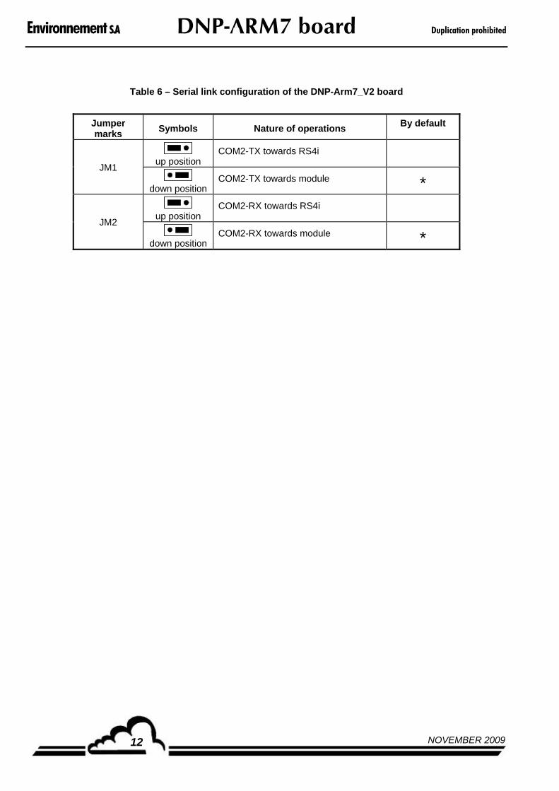
Environnement S.A DNP-ARM7 board Duplication prohibited
NOVEMBER 200912
Table 6 – Serial link configuration of the DNP-Arm7_V2 board
Jumper marks
Symbols Nature of operations By default
up position
COM2-TX towards RS4i
JM1
down position COM2-TX towards module *
up position
COM2-RX towards RS4i
JM2
down position COM2-RX towards module *


