Kit Satelite Digital MAXS101/S212/ SL30 Antena 100cm LNB - Manual Sonigate
MOUNTINSTALLATION
GUIDE
13 Nov '12

Mount Installation Guide
2

Mount Installation Guide
3
WARNINGMake all electrical and coax connections from the controller to themount and LNB's BEFORE applying power to, or connecting thesatellite receiver to the controller.
Note: When the controller is turned OFF it will still pass voltage from the receiver to theLNB if the receiver is plugged in to 110 AC. Shorting of the coax at any time duringinstallation may cause damage to either the Controller or the DiSEqC Switch. Failure tofollow this procedure can result in voiding of warranty replacement, not to mention timespent trying to troubleshoot a system that does not perform.
90% of all problems are a result of CONNECTIVITY or CONFIGURATION.
Tools and Hardware RequirementsThis is a list of tools and hardware that you might use in the installation of the system.
TOOLS #2 Philip screwdriver 3/32 Flat blade screwdriver for use on the 12 Pin green control cable connector 1/2" drill bit Appropriate size drill bit for pre-drilling of mounting holes in fiberglass roofs Cordless battery for raising the dish from its shipped position Cable cutters for shortening the control cable Wire strippers for preparing the control cable
HARDWARE and SUPPLIES Dicor or a lap sealant approved for the type of roof you are installing the mount on Dielectric grease or jell for moisture protection of all outdoor coax connections 16-20 ea. #12 Stainless Steel screws for securing the mount to the roof 6-8 ea. #8 Stainless Steel screws for securing the Clam Shell over cable entry hole 4" wire ties for securing and tidying up the cables inside the RV Cordless vacuum for interior cleanup
TOOLS REQUIRED BUT NOT SUPPLIED Common Sense

Mount Installation Guide
4
TABLE OF CONTENTS
DEFINITIONS ................................................ 5Mount Rotation Definitions ...................... 6Function of Antenna Movement................ 7
MOUNT COMPONENTSFront........................................................... 8Rear............................................................ 9
INSTALLATION MOUNTING PADS ......... 10
INSTALLATION OF vGPS ............................11
vGPS for DirecTV............................................. 12
vGPS for SHAW Direct ................................... 13
FEATURES AND OPERATION.................... 14
MOUNT ROTATIONAL CLEARANCES.... 15
BILL OF MATERIALS................................... 16
MOUNTING HINTS....................................... 17
WIRING DIAGRAMS......................................18
ROOF CONNECTOR HOUSINGS ............... 21
FIELD SERVICE RELATED PARTS.......... 22
SUPPORT ......................................................... 23Parts return procedureSupport contact information

Mount Installation Guide
5
DEFINITIONS
The mount consists of several components that make it up.
DISH, REFLECTOR, PARABOLAReceives signal from the satellite and reflects it into the LNB.
LNBFReceives the focused signal from the dish and blocks the noise from the signal and sends it to the satellite
receiver by way of the coax, hence, it is called a Low Noise Blocker (Feed).
vGPSVirtual Ground Positioning System is used to calculate Elevation and Skew when required by the system.
LNB ARMHolds the LNB in the proper focal point of the Dish.
DISH SUPPORT ARMSAttaches the dish and skew assembly to the Base Unit.
SUPPORT ARM ATTACHMENT BOLTSSecuring bolts that secure the Dish Support Arms to the Base Unit.
BASE UNITPerforms the rotating functions in both Azimuth and Elevation. It is attached to the roof of the RV by screws
or bolts.
Dish, Reflector, Parabola
LNBF
LNB Arm
Dish/Skew Support Arms
Base Unit
Dish Support ArmsAttachment Bolts
LNB size will vary inconfiguration dependingupon service requirements.
vGPS will be mounted here
Mount Installation Guide
6
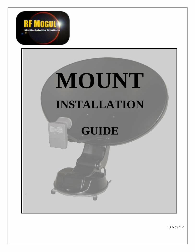
MOUNT ROTATIONSThe mount will use the rotation of three (3) axis to achieve acquisition. Terminology is helpful when
conversing with your installing dealer or a factory support technicians. Earlier in this manual you weregiven instruction concerning the components of the mount. We will now discuss the rotation of the mountand what is accomplished with each movement.
Rotation of the base in a clockwise/counter clockwise is call
AZIMUTH
Tilting of the antenna from sideto side is called SKEW
The antenna in the travelposition is called STOWED
To FRONT of vehicle
Antenna in the upright positionand not moving is called
DEPLOYED
Movement of the antenna from the STOWED positionto the DEPLOYED position is called ELEVATION
Mount Installation Guide
7
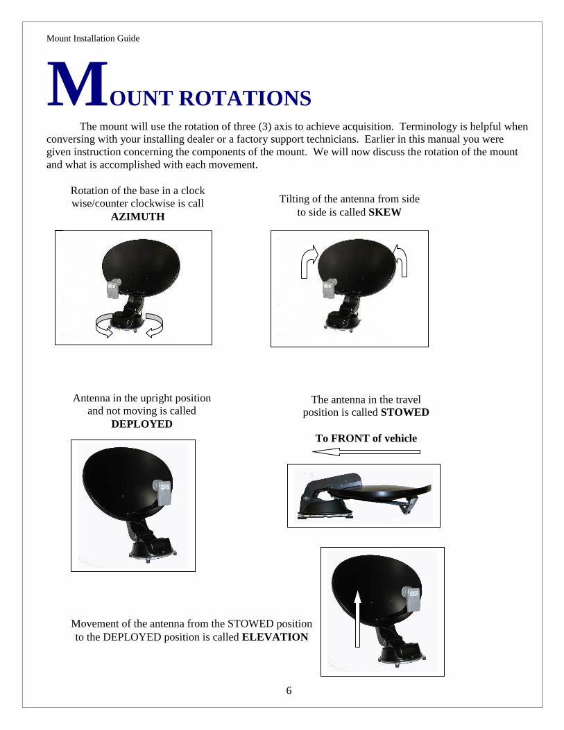
FUNCTION OF ANTENNA MOVEMENT
AZIMUTHOnce the antenna is deployed, the Controller (Indoor Unit) will instruct the mount to rotate clockwise
and then counter clockwise to sweep the sky for satellites. If the system does not see a satellite that it canidentify once it rotates to its clockwise or counter clockwise, as it stops against an azimuth limit it will go up2 degrees and reverse directions. If it does not see a satellite that it can identify on this pass when it hits theopposing limit it will go down 4 degrees in elevation. If nothing seen, it will go up 6 degrees, ever wideningits search pattern until it has swept a "box" in the sky. If nothing is found in this search pattern the systemwill display an error as to what it thinks is wrong.
SKEWOnce the controller has identified two satellites or has input from a vGPS, it will calculate the arc in
which the satellites reside and tilt the antenna (and LNB's) to align each LNB at the end of the LNB Armwith their appropriate satellites. If you travel from Southern Florida to Southern California the skew anglewill change dramatically. It will tilt or skew the antenna an opposite or more extreme direction. It willchange somewhere in the middle of the country depending upon the satellites that you are looking for.
DEPLOYEDIf the mount has quit moving it has probability acquired, identified and maintained a high signal lock
and you are probably watching TV.
STOWEDWhen the mount is given a command to stow, it will elevate fully to clear any object on your roof,
bring skew into a neutral position and then rotate in azimuth until it hits an azimuth limit. At that time it willmove down in elevation until it comes to rest in a travel position. This is an important step. This willprevent the automatic stow feature that an overpass provides. (just checking to see if you were reading themanual).
ELEVATIONThe controller remembers its last elevation that it saw when it last identified a satellite. It will rise to
that specific elevation to shorten your search time. If the system has a vGPS then that device will providethe controller with the proper required information for proper satellite acquisition.

Mount Installation Guide
8
MOUNT COMPONENT (Front View)
Control cable and Coaxcables enter the mount
here.
Azimuth Limit Bar
Azimuth Limit SensorElevation Motor/Gearbox
Assembly
Azimuth Motor/GearboxAssembly
Mount Installation Guide
9
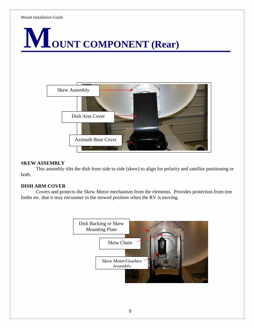
MOUNT COMPONENT (Rear)
SKEW ASSEMBLYThis assembly tilts the dish from side to side (skew) to align for polarity and satellite positioning or
both.
DISH ARM COVERCovers and protects the Skew Motor mechanism from the elements. Provides protection from tree
limbs etc. that it may encounter in the stowed position when the RV is moving.
Skew Assembly
Dish Arm Cover
Skew Motor/GearboxAssembly
Skew Chain
Dish Backing or SkewMounting Plate
Azimuth Base Cover

Mount Installation Guide
10
INSTALLATION MOUNTING FEET (PADS)
The Mount will be shippedwith the Mounting Padsrotated into the "shipping"position. They will berotated and secured prior toinstallation. For roofs thathave a stable platform theymay be installed in thisposition.
The Mount will be shippedwith the Mounting Padsrotated into the "shipping"position. They will berotated and secured prior toinstallation. For roofs thathave an unstable platformthey may be installed in the"open" position.
INSTALLATION MOUNTING PADS
Width = 36"
Length 34"
Stowedmount
dimensions

Mount Installation Guide
11
INSTALLATION OF vGPS
The vGPS is a device that is affixed next to the DirecTV SWM or SHAW Direct LNB. It is used in theacquisition sequence of controller. It is critical that the vGPS be installed and wired according to thefollowing information. Failure to do so will make the system inoperable. vGPS mounts, when facing thedish, on the left side of the LNB as pictured.
vGPS
vGPS Bracket
Mount Installation Guide
12
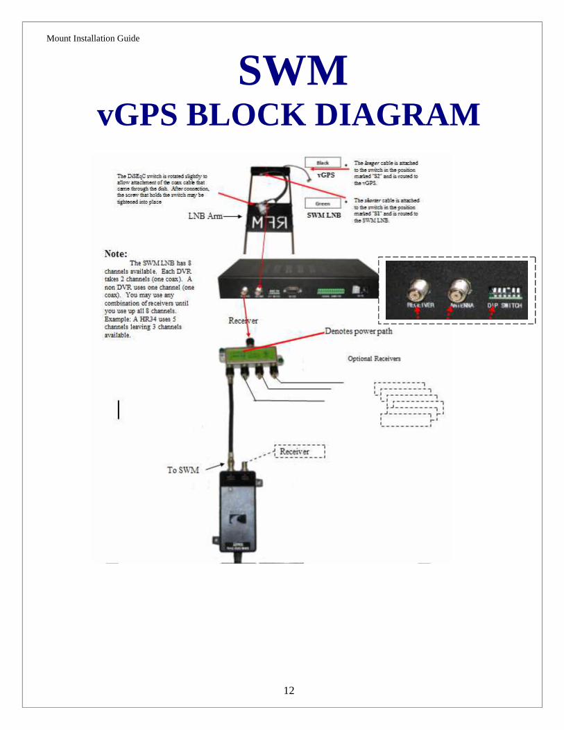
SWMvGPS BLOCK DIAGRAM

Mount Installation Guide
13
SHAW Direct

Mount Installation Guide
14
FEATURES AND OPERATION
The mount is designed to respond from electronic signals from the controller (In Door Unit) to raise itfrom its stowed position and align itself automatically on the selected satellite(s).
To operated the system follow these steps:1. Initially you will want to make sure the Dip Switches are set properly based on your configuration
requirements.2. Turn ON Power to the controller3. If you want to raise the dish or search for satellite(s), press SEARCH4. If you want to stow the dish, press STOW5. The RFM-1000/1100 Controller will shut OFF power after completing SEARCH or STOW
procedure.
If you want to watch satellite TV, after following the above procedures:1. Turn ON your TV2. Turn ON your satellite receiver3. Watch satellite TV
This mount is "Field Serviceable". Most all components that make up this mount may be replaced orrepaired in the field by the consumer or a RF Mogul dealer. There is practically no part of this mountthat cannot be repaired or replaced in the field.
Mount Installation Guide
15
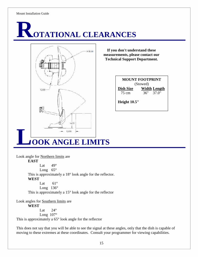
ROTATIONAL CLEARANCES
LOOK ANGLE LIMITS
Look angle for Northern limits areEAST
Lat 49°Long 65°
This is approximately a 18° look angle for the reflector.WEST
Lat 61°Long 136°
This is approximately a 15° look angle for the reflector
Look angles for Southern limits areWEST
Lat 24°Long 107°
This is approximately a 65° look angle for the reflector
This does not say that you will be able to see the signal at these angles, only that the dish is capable ofmoving to these extremes at these coordinates. Consult your programmer for viewing capabilities.
If you don't understand thesemeasurements, please contact ourTechnical Support Department.
MOUNT FOOTPRINT(Stowed)
Dish Size Width Length 75 cm 36" 37.0"
Height 10.5"

Mount Installation Guide
16
BILL OF MATERIALS
Your system, when ordered as a system, comes with the following items:
1 ea. Mount consisting of the base, reflector, LNB Arm and LNB (the Mount) 1 ea. LNB Landing Plate 15 ft. 20 gauge, 12 conductor control cable (terminated with water tight connector on the mount end) 1 ea. 12 pin connector for securing the control cable to the controller 1 ea. Controller (Indoor Unit) 1 ea. 12v 7 amp Power Supply for the controller 1 ea. User Guide 1 ea. Product Registration Card 1 ea. Wiring and Configuration charts
If the system is DirecTV SWM or SHAW Direct you will receive.. 1 ea vGPS 1 ea vGPS Mounting Bracket
Things that the installing dealer will supply:
Lap Sealant designed for the specific roof of the install Stainless Steel screws for securing the mount, LNB Landing plate and Connector Housing to the roof RG6U coax Coax connectors Loom for encasing cable on the roof (optional) Cable clamps or straps used to secure the cables to the roof (optional)
What is required but not supplied Common sense
Mount Installation Guide
17
MOUNTING HINTS
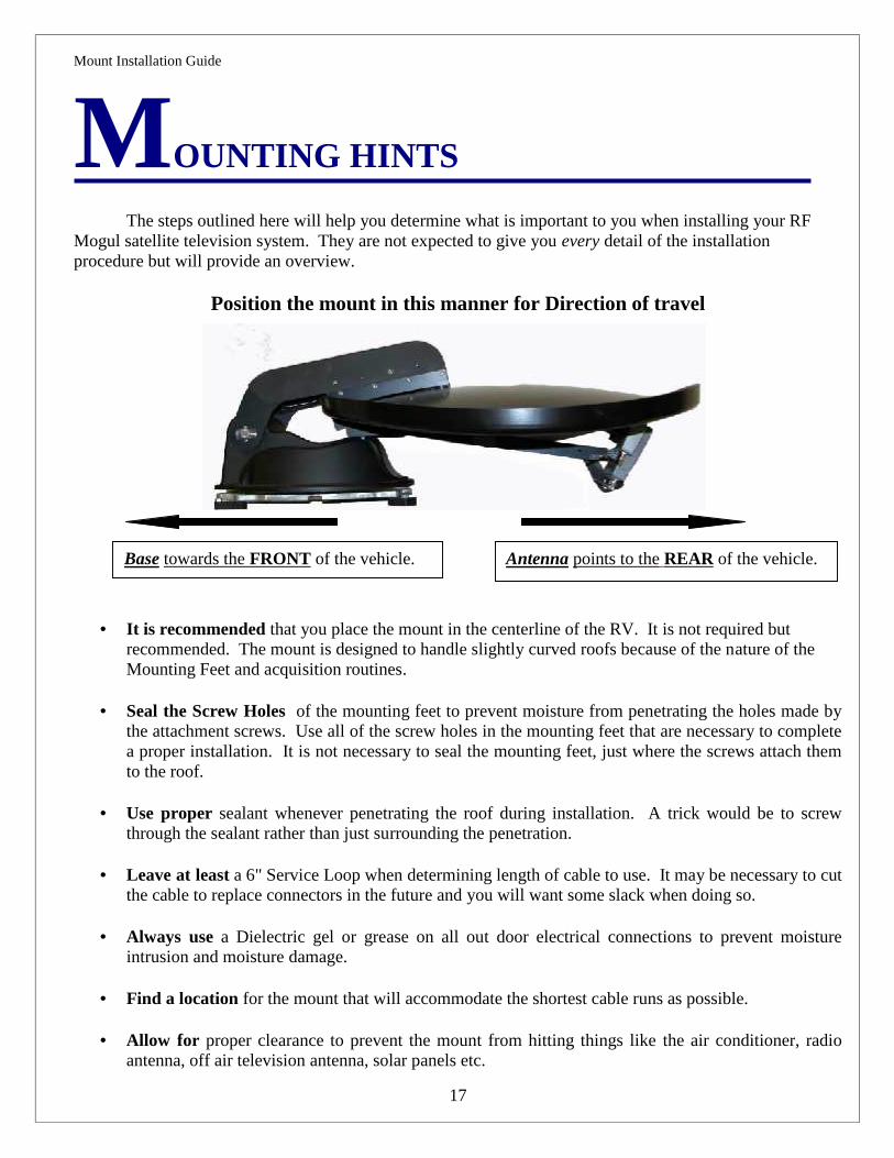
The steps outlined here will help you determine what is important to you when installing your RFMogul satellite television system. They are not expected to give you every detail of the installationprocedure but will provide an overview.
Position the mount in this manner for Direction of travel
It is recommended that you place the mount in the centerline of the RV. It is not required butrecommended. The mount is designed to handle slightly curved roofs because of the nature of theMounting Feet and acquisition routines.
Seal the Screw Holes of the mounting feet to prevent moisture from penetrating the holes made bythe attachment screws. Use all of the screw holes in the mounting feet that are necessary to completea proper installation. It is not necessary to seal the mounting feet, just where the screws attach themto the roof.
Use proper sealant whenever penetrating the roof during installation. A trick would be to screwthrough the sealant rather than just surrounding the penetration.
Leave at least a 6" Service Loop when determining length of cable to use. It may be necessary to cutthe cable to replace connectors in the future and you will want some slack when doing so.
Always use a Dielectric gel or grease on all out door electrical connections to prevent moistureintrusion and moisture damage.
Find a location for the mount that will accommodate the shortest cable runs as possible.
Allow for proper clearance to prevent the mount from hitting things like the air conditioner, radioantenna, off air television antenna, solar panels etc.
Base towards the FRONT of the vehicle. Antenna points to the REAR of the vehicle.
Mount Installation Guide
18
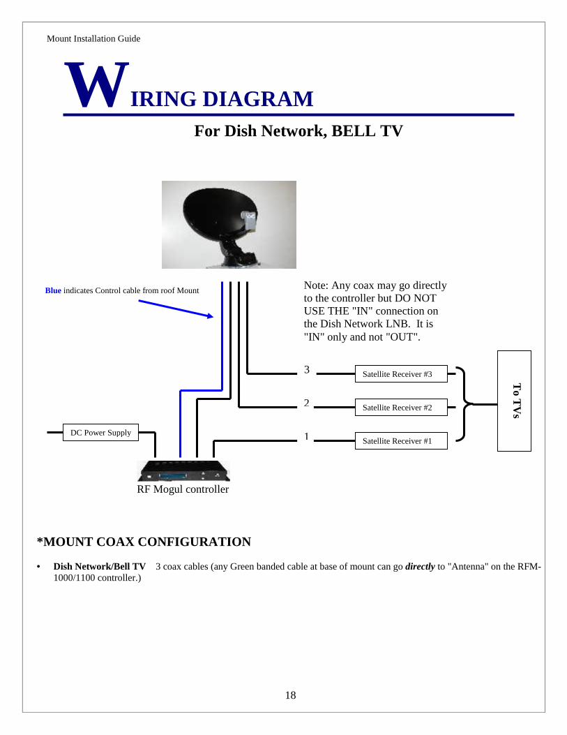
WIRING DIAGRAMFor Dish Network, BELL TV
Satellite Receiver #3
Satellite Receiver #2
Satellite Receiver #1
To T
Vs
DC Power Supply
Blue indicates Control cable from roof Mount
RF Mogul controller
*MOUNT COAX CONFIGURATION
Dish Network/Bell TV 3 coax cables (any Green banded cable at base of mount can go directly to "Antenna" on the RFM-1000/1100 controller.)
1
2
3
Note: Any coax may go directlyto the controller but DO NOTUSE THE "IN" connection onthe Dish Network LNB. It is"IN" only and not "OUT".

Mount Installation Guide
19
WIRING DIAGRAMFor SHAW Direct Configuration
Satellite Receiver #4
##1#1
Satellite Receiver #3
Satellite Receiver #2
Satellite Receiver #1
To T
Vs
DC Power Supply
Blue indicates Control cable from roof Mount
RF Mogul controller
*MOUNT COAX CONFIGURATION
SHAW Direct - 4 coax cables (the Red banded cable at base of the mount goes directly to the RFM-1000/1100 controller.)
1
2
3
4
* RED banded Coax goes directly tothe RFM-1000/11000 controller.

Mount Installation Guide
20
WIRING DIAGRAMFor DirecTV SWM Configuration
Satellite Receiver #4
##1#1
Satellite Receiver #3
Satellite Receiver #2
Satellite Receiver #1
To T
Vs
DC Power Supply
Blue indicates Control cable from roof Mount
RF Mogul controller
SW
M S
plitter
DirecTV SWM requires just a singlecoax cable for its SWM service.Multiple coax cables are not required.See "vGPS Block Diagram" in thismanual for more details.
This coax cable goes directly to the RFM-1000/11000 controller.
SWM
21 VD
C Pow
erInserter
Note: The SWM LNB canservice up to 8 channels inany combination of usage.
Mount Installation Guide
21
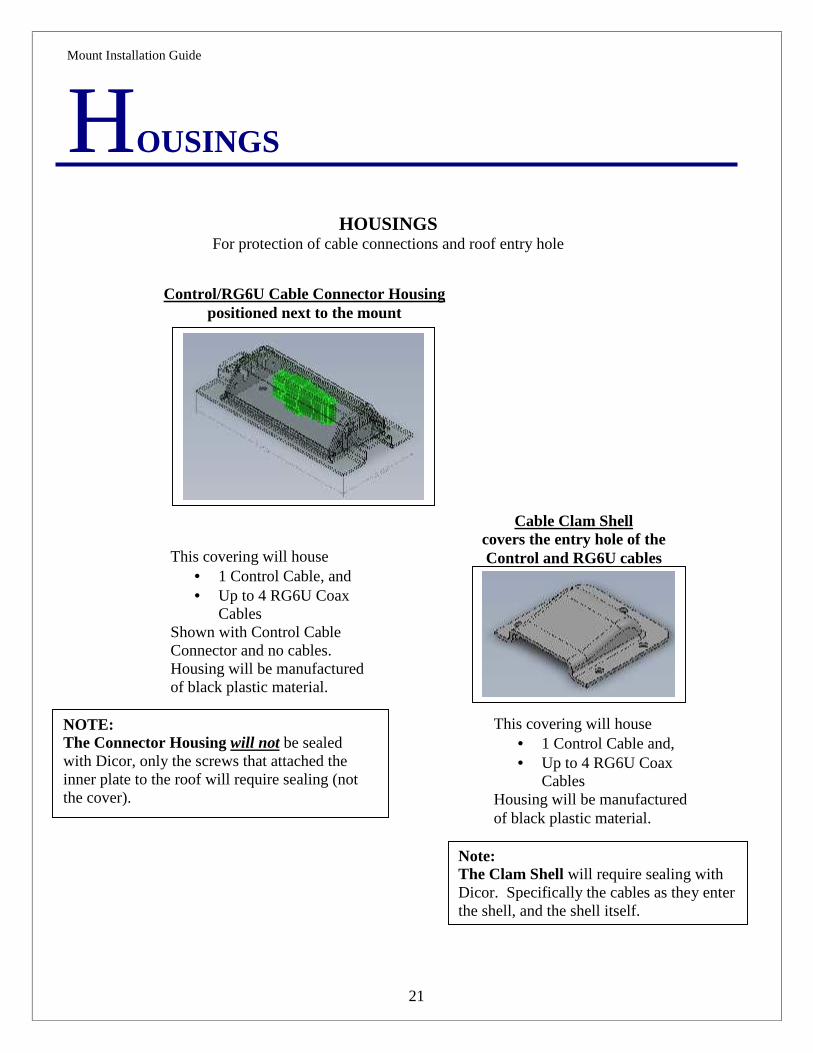
HOUSINGS
Control/RG6U Cable Connector Housingpositioned next to the mount
Cable Clam Shellcovers the entry hole of theControl and RG6U cables
This covering will house 1 Control Cable and, Up to 4 RG6U Coax
CablesHousing will be manufacturedof black plastic material.
This covering will house 1 Control Cable, and Up to 4 RG6U Coax
CablesShown with Control CableConnector and no cables.Housing will be manufacturedof black plastic material.
NOTE:The Connector Housing will not be sealedwith Dicor, only the screws that attached theinner plate to the roof will require sealing (notthe cover).
HOUSINGSFor protection of cable connections and roof entry hole
Note:The Clam Shell will require sealing withDicor. Specifically the cables as they enterthe shell, and the shell itself.
Mount Installation Guide
22
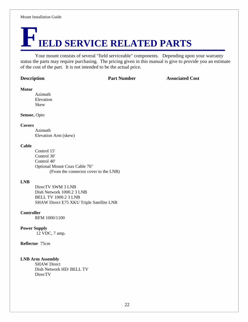
FIELD SERVICE RELATED PARTSYour mount consists of several "field serviceable" components. Depending upon your warranty
status the parts may require purchasing. The pricing given in this manual is give to provide you an estimateof the cost of the part. It is not intended to be the actual price.
Description Part Number Associated Cost
MotorAzimuthElevationSkew
Sensor, Opto
CoversAzimuthElevation Arm (skew)
CableControl 15'Control 30'Control 40'Optional Mount Coax Cable 76"
(From the connector cover to the LNB)
LNBDirecTV SWM 3 LNBDish Network 1000.2 3 LNBBELL TV 1000.2 3 LNBSHAW Direct E75 XKU Triple Satellite LNB
ControllerRFM 1000/1100
Power Supply 12 VDC, 7 amp.
Reflector 75cm
LNB Arm AssemblySHAW DirectDish Network HD/ BELL TVDirecTV
Mount Installation Guide
23
SUPPORT
This system was designed to provide years of trouble free service. Should a question ariseconcerning operation please call your installing dealer first and then if required call RF Mogul at 801-895-3392 and ask for Technical Support. You will provided with answers to your questions.
RETURNING PARTS TO THE FACTORY
Parts returned to the factory must contain a Return Material Authorization (RMA) which will be provided bythe RF Mogul Technical Support Department at the time of troubleshooting. This will ensure properaccountability of returned equipment or parts. Make sure that the following information is contained on yourshipment.
RF MogulAttn: Product Evaluation DepartmentRMA # _______________3604 South Via TerraSouth Salt Lake City, UT 84115
You must include your Return Address and Telephone Number failure to do so may result in you beingbilled for a non-returned part.
Thank you for purchasing a RF Mogul System.We appreciate your business. If you need to contact us please seethe information below.
RF Mogul3604 Via TerraSouth Salt Lake City, UT 84115Tele 801-895-3392 (Direct)Fax [email protected]@rfmogul.com