Motor pumps and hydraulic units type R and RG...Motor pumps and hydraulic units type R and RG Pump...
19
Motor pumps and hydraulic units type R and RG Pump units with radial-piston pumps ace. to D 6010 ready for installation and operation D 6010 H Hydraulic units type R, RG March 2008-01 HAWE HYDRAULIK SE STREITFELDSTR. 25 • 81673 MÜNCHEN 1.2 © 1993 by HAWE Hydraulik Radial piston pumps type R and RG D 6010 Radial piston pumps type R and RG with several pressure outlets D 6010 D Radial piston pumps type R and RG with one main and one or two auxiliary outlets D 6010 S Hydraulic power packs type R and RG with several pressure outlets D 6010 DB Hydraulic power packs type R and RG with DC-drive motor D 6010 HDC Operating pressure p max = 700 bar Delivery flow Q max = 91.2 lpm (at 1450 rpm) Geometric displacement V g max = 64.2 cm 3 /rev. Motor pumps, see 2.1 on page 2 and 2.2 on page 3 For separate installation outside an oil tank Ready for mount- ing at industrial standard motor, design IM B 35 Ready for connec- tion motor pump incl. industrial standard motor, design IM B 35 1. Overview Ready for mounting and piping in customer furnished cover plate and tank, with/with- out industrial standard motor, design IM B5 Cover plate version for mounting on customer furnished tank, with/without industrial standard motor, design IM B5, with/without pressure limiting valve. Ready for connection power pack, with/ without industrial standard motor, design IM B5, with/without pressure limiting valve. Hydraulic power packs, see 2.1 on page 2 and 2.3 on page 4 ++
Transcript of Motor pumps and hydraulic units type R and RG...Motor pumps and hydraulic units type R and RG Pump...

Motor pumps and hydraulic units type R and RGPump units with radial-piston pumps ace. to D 6010 ready for installation and operation
D 6010 HHydraulic units type R, RG
March 2008-01
HAWE HydRAulik SESTREITFELDSTR. 25 • 81673 MÜNCHEN
1.2
© 1993 by HAWE Hydraulik
Radial piston pumps type R and RG D 6010Radial piston pumps type R and RG with several pressure outlets D 6010 DRadial piston pumps type R and RG with one main and one or two auxiliary outlets D 6010 SHydraulic power packs type R and RG with several pressure outlets D 6010 DBHydraulic power packs type R and RG with DC-drive motor D 6010 HDC
Operating pressure pmax = 700 barDelivery flow Qmax = 91.2 lpm (at 1450 rpm)Geometric displacement Vg max = 64.2 cm3/rev.
Motor pumps, see 2.1 on page 2 and 2.2 on page 3
For separate installation outside an oil tank
Ready for mount-ing at industrial standard motor, design IM B 35
Ready for connec-tion motor pump incl. industrial standard motor, design IM B 35
1. Overview
Ready for mounting and piping in customer furnished cover plate and tank, with/with-out industrial standard motor, design IM B5
Cover plate version for mounting on customer furnished tank, with/without industrial standard motor, design IM B5, with/without pressure limiting valve.
Ready for connection power pack, with/ without industrial standard motor, design IM B5, with/without pressure limiting valve.
Hydraulic power packs, see 2.1 on page 2 and 2.3 on page 4 ++

D 6010 H page 2
4 5 6
(350) 2)600
(300) 2)550
250 450 350 300 250 200 160
87 9 10 12 13 14 15 16
30,9
(0.64)
1,25
(0.88)
1,5
(1.15)
2,5
(1.79)
3,6
(2.58)
4,3
(3.03)
5,1
(3.51)
5,6
(4.03)
6,5
(4.58)
4212,7
(9.03)
17,45
(12.28)
22,0
(16.04)
34,5
(25.07)
51,0
(36.10)
60,0
(42.37)
70,0
(49.14)
80,0
(56.41)
91,2
(64.18)
0,42(0.29)
0,64(0.42)
0,27(0.19)
0,46(0.31)
0,3(0.21)
0,41(0.29)
0,5(0.38)
0,6(0.43)
0,83(0.58)
1,0(0.76)
0,7(0.49)
1,08(0.71)
1,39(0.96)
1,77(1.26)
2,27(1.59)
0,8(0.60)
1,6(1.19)
1,2(0.86)
1,45(1.01)
1,7(1.17)
1,9(1.34)
2,2(1.53)
2,8(2.02)
2,4(1.72)
3,3(2.34)
3,8(2.69)
4,4(3.06)
0,81(0.58)
1,1(0.75)
1,35(0.95)
0.25 to0.75
0.25 to 1.1
0.25 to 2.2
0.25 to 3
0.55 to 4
0.55 to 5.5
2.2 to 7.5 (9)
2.2 to 11
5.5 to 18.5
5.5 to 22
11to30
0,28(0.20)
0,18(0.13)
0,43(0.28)
0,56(0.38)
0,73(0.50)
0,92(0.64)
0.25 to 0.55
550700 (450) 2)700
Num
ber
of p
ump
cy
lind
ers
2
3
5
1
2
1,4(1.07)
2,08(1.46)
2,6(1.91)
2,1(1.50)
2,9(2.05)
3,7(2.67)
4,2(2.98)
5,8(4.18)
6,0(4.30)
7,0(5.04)
8,3(5.85)
9,5(6.72)
10,9(7.64)
9,8(7.06)
8,4(6.02)
11,8(8.19)
13,3(9.40)
15,3(10.70)
5
7
2,7(2.15)
4,15(2.92)
5,3(3.82)
4,0(3.01)
5,85(4.09)
7,4(5.35)
8,2(5.97)
11,6(8.36)
12,0(8.60)
14,2(10.09)
16,8(11.70)
19,3(13.43)
21,7(15.28)
20,0(14.12)
17,0(12.03)
23,5(16.38)
26,5(18.80)
30,4(21.39)
10
20
14
6,1(4.30)
8,35(5.85)
11,0(7.64)
8,0(6.02)
11,65(8.19)
15,0(10.70)
17,4(11.94)
23,0(16.71)
25,0(17.19)
30,0(20.18)
35,0(23.40)
38,0(26.86)
43,4(30.56)
40,0(28.24)
34,0(24.07)
47,0(32.76)
53,0(37.60)
60,8(42.79)
28
2. Available versions, main data
2.1 Radial piston pump acc. to D 6010for motor pumps, see sect 2.2 and for hydraulic power packs, see sect. 2.3
1) The operating pressure should be restricted for applications with continuous operation where the subsequent load cycles are all at the upper end of the pressure range (>75%) e.g. accumulator charging etc.
It is advisable for an economic service life of the bearings to restrict the operating pressure of the respective pump element diameter to about 75% of its original specification. Another pump with smaller but more pump elements should be selected, if this is not possible.
2) Figures in brackets apply to design 7631
Table 1a: Basic type coding
R Standard, roller bearing version
RG Slide bearing version
Table 1b: Delivery flow coding
Design, cylinder ar-rangement
Design76312-, 3-, and 5-cylinder pump
Design 60101- and 2-cylinder pump
Design 60103-cylinder pump
Design 60111-radial pump
Design 60122-radial pump
Design 60144-radial pump
Design 60166-radial pump
Delivery flow coding (guideline figure Q in (lpm) at 1450 rpm)Figures in brackets show the geometric displacement (cm3/rev.)
Piston diameter (mm)
Max. permissible operating pressure pmax (bar) 1)
Drive power rating (indus-trial standard motor)
(kW)
7631 6010 6011 6012 6014 6016 Main dimensions
7631 60116010 60166012 6014
2 3 5 1 a. 2 3 5 7 10 14 20 28 42
3 3.1 3.2 2.5 3.1 5.0 5.8 8.7 10.5 21.5 24.2 39.1
130 174 185 185 218 238
53 83 86 122 216 311
Design
No. of cylinders
Mass (weigth) approx. (kg)
D (mm)
I (mm)

D 6010 H page 3
2.2 Motor pumps
For a listing of standard bell housings and flex-couplings, see sect. 6.2
Order example: Ready for mounting at industrial standard motor
Ready for connection motor pump incl. in-dustrial standard motor
R 4,0 / W 4 R 17,0 / M 7,5
Motor voltage 3~230/400V 50Hz
Basic pump acc. to table 1a and 1b
Table 2: Motor/Pump design
oo o
o o o o
o o o o
o o o
o o o
o o o
0,250,37
0,550,75
1,11,5
2,234
5,57,5(9) 2)
1115
18,522
30
7631
6010
6011
6012
6014
6016
Available combina-tions with pump de-sign acc. to sect. 1
Drive power (kW) 1)
M
WReady for mounting at industrial standard motor, design IM B 35
Ready for connection motor pump incl. industrial standard motor, design IM B 35
1) Additional data regarding radial piston pump acc. to D 6010- Power requirements, see sect. 3
- Dimensions of bell housings and flexcouplings, see sect. 4
2) A motor with this output is not standardized, but usually is like indus-trial standard 132 M. Drive power too high for design 6011.
Unit dimensions
All dimensions in mm, subject to change without notice!
Flex-coupling
Bellhousing
For dimensions and mass (weight) of the pump, see sect. 2.1
Mass (weight) approx. kg (substantial are the spec. of the manufacturer)
Power rating (kW)
Motor
3)
Suited bell housingss and flex-cou-plings for combination with design
7631 6010 6011 6012 6014 60160.25 a. 0.37 3.1 3.10.55 a. 0.75 3.5 3.5
1.11.52.234
5.57.5 a. 9
1115
18.522 140 ... 185
80 ... 11060 ... 8045 ... 5828 ... 3523 ... 2420 ... 21
1512 ... 149 ... 106 ... 7.3
170 ... 240
115 ... 170100 ...145
30
3.83.53.5
6.4
11.9
6.4
8.9
8.8 9.9
9.2 10.3
6.4
3.8 3.9 4.0
3.8 4.03.9
Ext. flange-#D (mm)
Power rating(kW) 7631 6010 6011 6012 6014 6016 h a b #s w1 k 4)
Bellhousing length l (mm), when combined with design Outline dimensions of industrial standard motor 4)
190 ... 210
215 ... 230
240 ... 250
265 ... 270
280 ... 320
315 ... 320
330 ... 360390 ... 400
500 ... 520
500 ... 550
500 ... 550
550 ... 580
620 ... 650
0.25 a. 0.37
0.55 a. 0.75
1.1
1.5
2.2
3
4
5.5
7.5 and 9
11
15
18.5
22
30
160
200
200
250
250
300
350
350
400
83
109
212
113 113 123
109123
109 123109
113
188 209
188 188 209
160 160 160
113 123
83 71
80 100 125 9
100140 9 (10)90
100 140 160 12 63
112 140 190 12 70
132 216 12 89
10814254210
254
140
178
160
180 279 14 (15) 121241
254
200 305 318 18 133
56
50
90 112 7 45
3) Guideline data for two makes, but substantial are the spec. of the manu-facturer!
4) Not standardized, guideline data for two makes, but substantial are the spec. of the manu-facturer! See also
DIN 42 673-4 and
DIN 42 677-4 (outline dimensions)
125

D 6010 H page 4
2.3 Hydraulic power packs
Version with tank acc. to order example 1 in sect. 2.3.1
Illustration of the order examples in sect. 2.3.1 and 2.3.2
Version incl. pressure lim-iting valve acc. to order example 1 in sect. 2.3.1
Motor pump for mounting in cus-tomer furnished tank acc. to or-der example 2 and 3 in sect. 2.3.2 (see also page 5)
Cover plate ver-sion acc. to order example 2 in sect. 2.3.2
2.3.1 Tank and cover plate versions B 6 to 40 and D 6 to 40 Usable filling volume approx. 6 to 45 l
For a listing of standard bell housings, flex-couplings, and inlet parts, see sect. 6.2
Order example 1:
Order example 2:
R 1,39 / B 6 K- V 0,55
R 5,8 / D 13.2 - V 2,2 - E/160
Motor voltage 3~ 230/400V 50 Hz
Motor voltage 3~ 230/400V 50 Hz
Basic pump acc. to table 1a and 1b
For connection blocks (optional), see sect. 2.3.3
Table 3b: Options 4)
3) The specified filling volumes are only guideline figures. There is a slight variation in the filling volume depending on the selected pump size and drive power (bell housing size). For additional notes, see sect. 5.2.
Type B 6 B 13 B 20 B 30 B 40
approx. ( l ) 9 ... 9,3 16 ... 17 24 ... 25 37 ... 39 52 ... 55
4) not available with AT-seals and PYD-seals
1) Additional data regarding radial piston pump acc. to D 6010
- Power requirements, see sect. 3 - Dimensions of shaft and flange, see
sect. 4
2) The selected bell housing L... acc. to 6.2 has to be specified in uncoded text, when a pump/motor combination -Z.. (acc. to order example 2 in sect. 2.3.1) for installation in a customer furnished tank is desired. There is a range of bell hous-ings suited for various drive power.
Note: For mass (weight) see sect. 4!
Coding
K
T
D
Version
Fluid level gauge
Temperature switch
Float switch
For data and additional versions, see sect. 6.1
Table 3a: Tank, cover plate, and motor
D 6
D 13.1
D 13.2
D 30
B 6
B 13
B 20
B 30 and B 40
31 and 45
20
13
6
Usable fill-ing volume 3) approx.
( l )
D 40
D 20
o o o
0,250,37
0,550,75
1,11,5
2,234
7631
o o o6010
o o o7631
o o o6010
o o o7631
o o o6010
o o o6010
o o o7631
oo o6011
oo o6011
‚‚ ‚6011 oo o
o
6011
o6012
o6012
o o6011
Available combina-tions with pump design
Cover plate version
Z .. Power pack without motor 2)
V .. Power pack incl. motor
Tank version Drive power (kW) 1) 2)

D 6010 H page 5
2.3.2 Tank or cover plate versions B 50 and D 50.1-B 400 and D 250.2 Usable filling volume approx. 60 to 450 l
Order example 1: Hydraulic power pack R 11,6 / B 75 ... - V 7,5 - A/315 Motor voltage 3~ 400V 50 Hz
Options, see table 3b on page 4
Connection blocks (option), see sect. 2.3.3
Motor/pump combination
R 8,3
R 1,5
- Z 3 4)
- V 0,75 Motor voltage 3~ 230/400V 50 Hz
Order example 2:
Order example 3:
Basic pump acc. to table 1a and 1b
Table 3c: Tank, cover plate, and motor For a listing of standard bell housings, flex-couplings, and inlet parts, see sect. 6.2
Note: For mass (weight) see sect. 4!
Tank version
Power pack without motor 4)
Power pack incl. motor
Z ..
V ..
Available combinations with pump design
Drive power (kW) 1) 4)
0,250,37
0,550,75
1,11,5
2,234
5,57,5(9) 2)
1115
18,522
30
o
o
o o o
o
o
o
o
o
o
o
o
o
o
o
o
o
o
o
o
o
6010
6011
6012
6010
6011
6012
6014
6011
6012
6014
6016
6011
6012
6014
6016
6014
6016
6014
6016
o o
o
o o
o o o
o o
o o o
o
oo
o o
o
o
o oo
o o
o o
o o o
o o
o oo
B 50 60
Usable filling volume 3) ap-prox. ( l )
B 75
B 100 120
B 160 160
B 250 260
B 400 450
80
D 250.1
D 250.2
D 100.2
D 100.1
D 50.2
D 50.1
Cover plate version
1) Additional data regarding radial piston pump acc. to D 6010 - Power requirements, see sect. 3 - Dimensions of shaft and flange, see sect. 42) A motor with this output is not standardized, but usually is like industrial standard 132 M, i.e. also the optional
components (see sect. 6.2) will fit3) The specified filling volumes are only guideline figures. There is a slight variation in the filling volume depend-
ing on the selected pump size and drive power (bell housing size). For additional notes, see sect. 5.2.
Type B 50 B 75 B 100 B 160 B 250 B 400
approx. ( l ) 81 ... 85 98 ... 107 140 ... 152 180 ... 193 302 ... 309 461 ... 469
4) The selected bell housing L... acc. to 6.2 has to be specified in uncoded text, when a pump/motor combination -Z.. (acc. to order example 2 in sect. 2.3.1) for installation in a customer furnished tank is desired. There is a range of bell housings suited for various drive power.

D 6010 H page 6
2.3.3 Connection blocks
The connection blocks are mounted directly onto the cover plate of the power pack. A pressure limiting valve is always integrated whereas return filters are an option. It is possible to go on with directly mounted valve banks.
Order example: R 11,6 / B 75 - V 7,5 - A/ 315
R 5,8 / B 20 - V 2,2 - EF 1/ 160
Motor voltage 3 ~ 400V 50 Hz
Motor voltage 3 ~ 230/400V 50 Hz
Table 4: Connection blocks
Pressure setting. Take care that the perm. pressure of the respective pump is not exceeded!
Suited for tank or cover plate version
B 6 ... B 40D 6 ... D 40
B 50 ... B 400D 50 ... D 250
Max. pres-sure setting
pmax
(bar)
700
Filter area
approx.(cm2)
Filter fine-ness
Nom. flow
(lpm)
Return filter cartridge (MANN micro-Top)Filter material is soaked paper
Coding (Co. MANN)
1.2
2.8
2.8
2.8
3.0
1.4
5.4
7
15
---
21
32
---
---
637
1230
1900
3190
---
3190
5110 5.6
32
52
W 77/2
HAWE 6905 117 F1
---A /...
AF 0 /..
B / ...
BF 0 / ..
E / ...
EF 0 / ..
F / ...
FF 0 / ..
FF 1 / ...
FF 2 / ...
FF 3 / ...
EF 1 / ...
EF 2 / ...
EF 3 / ...
BF 1 / ...
BF 2 / ...
BF 3 / ...
B / ...
BF 4 / ...
BF 5 / ...
AF 1 / ...
AF 2 / ...
AF 3 / ...
A / ...
AF 4 / .. .
AF 5 / ...
HAWE 6905 117 F2
HAWE 6905 117 F3
---
WD 940/2
WD 962
Mass (weight)
approx.(kg)
approx. 12µm nom. 50 % -30 µm abs.
Tool adjustable
Manually adjustable
Tool adjustable
Manually adjustable
Version
Utilized pressure limiting valves and pressure ranges
Tank, cover plate
Tank, cover plate
Connection block
Connection block
Pressure limiting valve
Pressure limiting valve
Pressure range bar
Pressure range bar
B 6 ... B 40D 6 ... D 40
A/.., B/.., E/.., F/..
AF 0(1,2,3)/.. to FF 0(1,2,3)/..
MVE 5 A (R) MVE 5 B (R) MVE 5 C (R) MVE 5 E (R) MVE 5 F (R)
MVF 5 A (R) MVF 5 B (R) MVF 5 C (R) MVF 5 E (R) MVF 5 F (R)
500 ... 700 315 ... 500 160 ... 315 80 ... 160 (0) ... 80
500 ... 700 315 ... 500 160 ... 315 80 ... 160 (0) ... 80
500 ... 700 315 ... 500 160 ... 315 80 ... 160 (0) ... 80
500 ... 700 315 ... 500 160 ... 315 80 ... 160 (0) ... 80
see D 7000/1
see D 7722
see D 7722
see D 7000 E/1
B 50 ... B 75 D 50
A/.., B/..
A/.., B/..B 100 ... B 400D 100 ... D 250
SVP(R) 30 A SVP(R) 34 B SVP(R) 34 D
200 ... 300 150 ... 200 (0) ... 150
B 50 ... B 400D 50 ... D 250
AF 4 (5) / .., BF 4 (5) / ..
SVP 6 A (R) SVP 6 B (R) SVP 6 C (R) SVP 6 E (R) SVP 6 F (R)
MVF 6 A (R) MVF 6 B (R) MVF 6 C (R) MVF 6 E (R) MVF 6 F (R)
Symbol acc. to order example R 17,0/B50 V7,5 - AF 5/220
Return filter
Suited directional valve banks for direct mounting
A/.., AF 0(1, 2, 3) /.. (B 6 ... B 40) SKP(H) 06 and 16 acc. to D 7230 B/.., BF 0(1, 2, 3) /.. BWN(H) 1C acc. to D 7470 B/1E/.., EF 0(1, 2, 3) /.. BWH 2(3) C acc. to D 7470 B/1 F/.., FF 0(1, 2, 3) /.. VB 01(11, 21) C acc. to D 7302
A/.., B/.. (B 50 ... B 75) SKP(H) 27 and 37 acc. to D 7230 AF4(5)/.., BF4(5) (B 50 ... B 400) SWR 1D acc. to D 7450 BWH 2(3) D acc. to D 7470 B/1 VB 11(21, 31) D acc. to D 7302
A/.. (B 100 ... B 400) SKP(H) 28 and 38 acc. to D 7230 B/.. VB 31E acc. to D 7302
Two mounting screws and two tapped plugs (if P and R are not used otherwise) have to be ordered additionally, when it is intended to directly mount directional valve banks
Connection block, complete
Skt. head screw conf. ISO 4762
Tapped plug(BSPP)
AF 0 (1,2,3) /.. to ...FF 0 (1,2,3) /.. (4000 640)
M 8x35-8.8-A2K
G 1/2 acc. to (943 008)
(6330 100 a..d)
M 10x50-8.8-A2K
G 1/2 acc. to (943 008)
AF 4 (5) / .. and BF 4 (5) / .. (6340 100 a..d)
M 12x60-8.8-A2K
G 3/4 acc. to (1980 010)
B 50
D 6010 H page 7
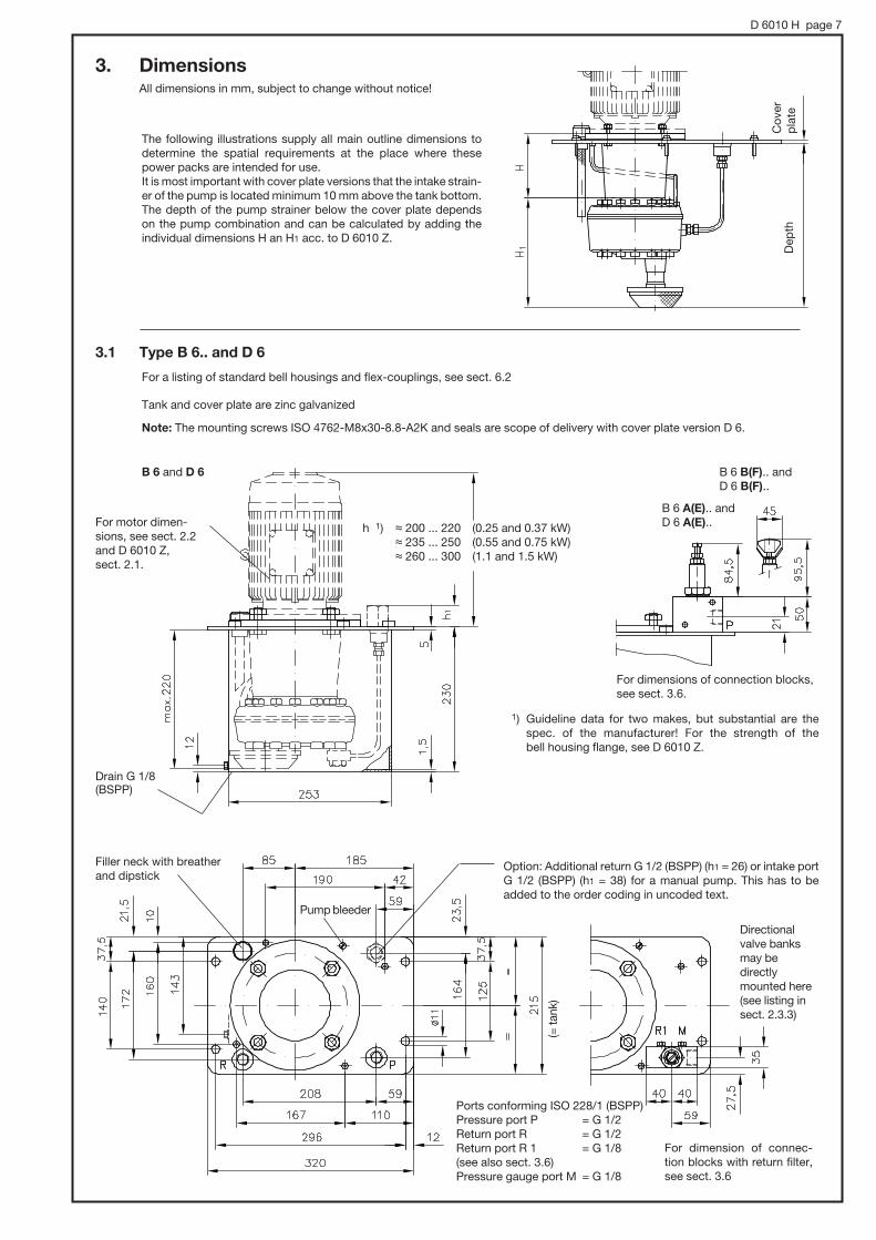
3. Dimensions All dimensions in mm, subject to change without notice!
The following illustrations supply all main outline dimensions to determine the spatial requirements at the place where these power packs are intended for use.It is most important with cover plate versions that the intake strain-er of the pump is located minimum 10 mm above the tank bottom. The depth of the pump strainer below the cover plate depends on the pump combination and can be calculated by adding the individual dimensions H an H1 acc. to D 6010 Z.
Dep
thC
over
p
late
3.1 Type B 6.. and D 6
For a listing of standard bell housings and flex-couplings, see sect. 6.2
Tank and cover plate are zinc galvanized
Note: The mounting screws ISO 4762-M8x30-8.8-A2K and seals are scope of delivery with cover plate version D 6.
B 6 and D 6
For motor dimen-sions, see sect. 2.2 and D 6010 Z, sect. 2.1.
h 1) , 200 ... 220 (0.25 and 0.37 kW) , 235 ... 250 (0.55 and 0.75 kW) , 260 ... 300 (1.1 and 1.5 kW)
B 6 B(F).. and D 6 B(F)..
For dimensions of connection blocks, see sect. 3.6.
1) Guideline data for two makes, but substantial are the spec. of the manufacturer! For the strength of the bell housing flange, see D 6010 Z.
Drain G 1/8 (BSPP)
Filler neck with breather and dipstick
Option: Additional return G 1/2 (BSPP) (h1 = 26) or intake port G 1/2 (BSPP) (h1 = 38) for a manual pump. This has to be added to the order coding in uncoded text.
Pump bleeder
(= ta
nk)
Directional valve banks may be directly mounted here (see listing in sect. 2.3.3)
Ports conforming ISO 228/1 (BSPP)Pressure port P = G 1/2 Return port R = G 1/2 Return port R 1 = G 1/8 (see also sect. 3.6)Pressure gauge port M = G 1/8
For dimension of connec-tion blocks with return filter, see sect. 3.6
B 6 A(E).. and D 6 A(E)..

D 6010 H page 8
For a listing of standard bell housings and flex-couplings, see sect. 6.2
3.2 Type B 13.. and B 20.. as well as D 13.1 to D 20
Tank and cover plate are zinc galvanized
Note: The mounting screws ISO 4762-M8x30-8.8-A2K and seals are scope of delivery with cover plate version D 13.1 to D 20.
B 13 and B 20D 13.1 to D 20
For motor dimen-sions, see sect. 2.2 and D 6010 Z, sect. 2.1.
B 13 B(F).. etc.D 13.1 B(F).. etc.
B 13 A(E).. etc.D 13.1 A(E).. etc.
For dimension of connection blocks, with return filter, see sect. 3.6
1) , 200 ... 220 (0.25 and 0.37 kW) , 235 ... 250 (0,55 and 0.75 kW) , 260 ... 300 (1.1 and 1.5 kW) , 300 ... 340 (2.2 and 3 kW) , 330 ... 350 (4 kW)
Guideline data for two makes, but sub-stantial are the spec. of the manufacturer! For the strength of the bell housing flange, see D 6010 Z.
Drain G 1/8 (BSPP)
Filler neck with breather and dipstick
Option: Additional return G 1/2 (BSPP) (h1 = 26) or intake port G 1/2 (BSPP) (h1 = 38) for a manual pump. This has to be added to the order coding in uncoded text.
Directional valve banks may be directly mounted here (see listing in sect. 2.3.3)
For dimension of connection blocks, with return filter, see sect. 3.6Ports conforming ISO 228/1 (BSPP): Pressure port P = G 1/2
Return port R = G 1/2 Return port R 1 = G 1/8 (see also sect. 3.6) Pressure gauge port M = G 1/8
Pump bleeder
( = T
ank)
D 6010 H page 9
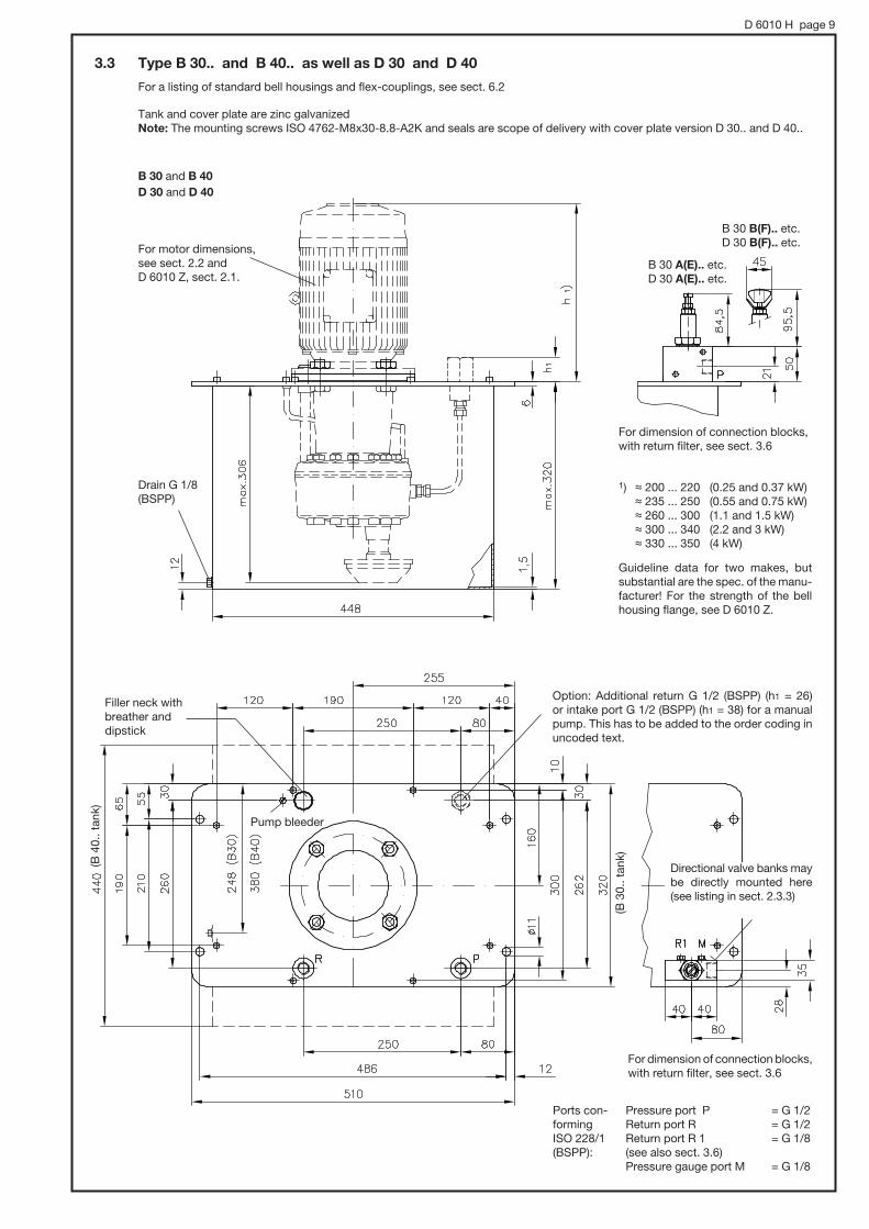
3.3 Type B 30.. and B 40.. as well as D 30 and D 40
Tank and cover plate are zinc galvanizedNote: The mounting screws ISO 4762-M8x30-8.8-A2K and seals are scope of delivery with cover plate version D 30.. and D 40..
For motor dimensions, see sect. 2.2 and D 6010 Z, sect. 2.1.
1) , 200 ... 220 (0.25 and 0.37 kW) , 235 ... 250 (0.55 and 0.75 kW) , 260 ... 300 (1.1 and 1.5 kW) , 300 ... 340 (2.2 and 3 kW) , 330 ... 350 (4 kW)
Guideline data for two makes, but substantial are the spec. of the manu-facturer! For the strength of the bell housing flange, see D 6010 Z.
Drain G 1/8 (BSPP)
Filler neck with breather and dipstick
Pump bleeder
(B 4
0.. t
ank)
(B 3
0.. t
ank)
Option: Additional return G 1/2 (BSPP) (h1 = 26) or intake port G 1/2 (BSPP) (h1 = 38) for a manual pump. This has to be added to the order coding in uncoded text.
Directional valve banks may be directly mounted here (see listing in sect. 2.3.3)
Pressure port P = G 1/2 Return port R = G 1/2 Return port R 1 = G 1/8 (see also sect. 3.6)Pressure gauge port M = G 1/8
B 30 B(F).. etc.D 30 B(F).. etc.
B 30 A(E).. etc.D 30 A(E).. etc.
B 30 and B 40 D 30 and D 40
For dimension of connection blocks, with return filter, see sect. 3.6
For dimension of connection blocks, with return filter, see sect. 3.6
Ports con-forming ISO 228/1 (BSPP):
For a listing of standard bell housings and flex-couplings, see sect. 6.2

D 6010 H page 10
3.4 Type B 50.. and B 75.. as well as D 50.1 and D 50.2
External surfaces of tank and cover plate are sprayed with gray primer
Note: The mounting screws ISO 4762-M6x16-8.8-A2K and seals are scope of delivery with cover plate version D 50..
For motor dimensions, see sect. 2.2 and D 6010 Z, sect. 2.1.
1) , 200 ... 220 (0.25 and 0.37 kW) , 235 ... 250 (0.55 and 0.75 kW) , 260 ... 300 (1.1 and 1.5 kW) , 300 ... 340 (2.2 and 3 kW) , 330 ... 350 (4 kW) , 410 ... 420 (5.5 to 9 kW) , 520 ... 570 (11 and 15 kW)
Guideline data for two makes, but substantial are the spec. of the manu-facturer! For the strength of the bell housing flange, see D 6010 Z.
Drain G 1/8 (BSPP)
ISO 4017 - M 6x16-8.8-A2K
Second return G 1
Filler neck with breather
Directional valve banks may be directly mounted here (see listing in sect. 2.3.3)
B 50 B.. etc.D 50.1 B.. etc.
B 50 A.. etc.D 50.1 A.. etc.
B 50 and B 75 D 50.1 and D 50.2
Type
B 50..
B 75..
H
403
478
h2
370
450
L
670
660
l
644
630
a
27
26
M 8, 10 deep
Pump bleeder
Dipstick
For dimension of connection blocks, with return filter, see sect. 3.6
For a listing of standard bell housings and flex-couplings, see sect. 6.2
Ports conforming ISO 228/1 (BSPP):Pressure port P = G 1/2 Return port R = G 1/2 Return port R 1 = G 1/4 (see also sect. 3.6)Pressure gauge port M = G 1/4Control connection Z 2) = G 1/4
2) only with version acc. to D 6010 S
1 )

D 6010 H page 11
3.5 Type B 100.. to B 400.. as well as D 100.1 to D 250.2For a listing of standard bell housings and flex-couplings, see sect. 6.2
External surfaces of tank and cover plate are sprayed with gray primer
Note: The mounting screws ISO 4017 M6 x 20 ... -8.8-A2K or ISO 4017 M8 x 20 ... -8.8-A2K and seals are scope of delivery with cover plate version D 100.1.. to D 250.2..
B 100 to B 400D 100.1 to D 250.2
For motor dimen-sions, see sect. 2.2 and D 6010 Z, sect. 2.1.
B 100 A.. etc.D 100.1 A.. etc.
B 100 B.. etc.D 100.1 B.. etc.
For dimension of connection blocks, with return filter, see sect. 3.6
1) B 100 (160) and D 100... :, 235 ... 250 (0.55 a. 0.75 kW), 260 ... 300 (1.1 and 1.5 kW), 300 ... 340 (2.2 and 3 kW), 330 ... 350 (4 kW), 410 ... 420 (5.5 to 9 kW), 520 ... 570 (11 and 15 kW)
B 250 (400) and D 250... :, 520 ... 570 (11 and 15 kW), 570 ... 610 (18,5 a. 22 kW), 640 ... 670 (30 kW)
Guideline data for two makes, but substantial are the spec. of the manufacturer! For the strength of the bell housing flange, see D 6010 Z.
Ports conforming ISO 228/1 (BSPP):Pressure port P = G 3/4 Return port R = G 3/4 Return port R 1 = G 1/2 (see also sect. 3.6)Pressure gauge port M = G 1/2 Control connection Z = G 1/4(only with version acc. to D 6010 S)
Directional valve banks may be directly mounted here (see listing in sect. 2.3.3)
M 10,10 deep
Second returnG 1 1/4
Pump bleederDipstickFiller neck with breather
Drain G 3/4 (BSPP)
Type
B 100
H
536 510500 650 26 470 475 250 295 40 45 145 195 190 150 M 6x20 105 46 190 680 625
666 640
575 510650 1000 27 620 625 375 465 45 80 165 250 290 315 M 8x20 160 101 240 1044 975
825 790
h2 B L1L
710
1070
a b b1 c c1 d d1 e e1 f f1 g i i1 k l l1
B 160
B 250
B 400
(B160 to B400)
g

D 6010 H page 12
3.6 Dimensions of connection blocks with return filter
Connection block AF 0/.. to FF 3/.. Connection block AF 4/.. to BF 5/..To
ol a
d-
just
able
Filter cartridge
Tool
ad
-ju
stab
le
Man
ually
ad
just
able
Man
ually
ad
just
able
Filter cartridge
Ports conforming ISO 228/1 (BSPP)
P = Pressure port G 1/2R1 = Return port G 1/2R2 = Return port G 1/4M = Pressure gauge port G 1/8
Directional valve banks may be directly mounted here (see listing in sect. 2.3.3)
Directional valve banks may be directly mounted here (see listing in sect. 2.3.3)
Apply some lube during re-placement of the filter cartridge
Apply some lube during replacement of the filter cartridge
Tank or cover plate size
a
b
B 6D 6
66
80
B 13, B 20D 13, D 20
115
102
B 30, B 40D 30, D 40
115
133
Filter coding
# D
L
F 0
78
59
F 1
78
93
F 2
78
123
F 3
93
144
L1 = 144 with filter cartridge F4 = 211 with filter cartridge F5
Tank or cover plate size
B 50, B 75D 50
B 100, B 160D 100
B 250, B 400D 250
406 165 118 50 26 63 100 56 71 G 3/4 G 1/4 G 1/2
247 120 100 38 22 50 90 54 64 G 1/2 G 1/4 G 1/4
a b c e f g h h1 i P, R1 R2 M
236 154 118 50 26 63 100 56 71 G 3/4 G 1/4 G 1/2
Ports ISO 228/1(BSPP)

D 6010 H page 13
4. Mass (weigth)
9.2 (6.2)
13.5 (9)
0.25 - 1.5 2.2; 3; 4
with drive power (kW)
Mass (weight) approx. (kg) with drive power (kW): First figure = tank versions, figures in brackets = cover plate versions
5.5; 7; 9 11; 15 18.5; 22 30
15 (9) 15.3 (9.5)
15.2 (9.3)
19.2 (11.7) 19.5 (12)
19.5 (12)
21.2 (11.7) 21.5 (12)
21.5 (12)
33.2 (16.2) 33.5 (16.5)
33.3 (16.3) 35 (18) 35.5 (18.5)
35.5 (18.5) 35.5 (18.5)
36 (16.5) 36 (16.5)
36 (16.5) 36 (16.5) 38.5 (19)
36 (16.5) 36 (16.5) 38.5 (19) 41 (21.5)
38.5 (19) 41.3 (22)
55.7 (24.7) 56.5 (25.5)
56.5 (25.5) 59.5 (28.5) 60.5 (29.5)
61 (30) 61 (30) 61 (30)
63 (32) 63 (32)
62.5 (25) 63.5 (26)
64 (26.5) 68 (30.5) 67.5 (30)
67.5 (30) 68.5 (31)
69.5 (32)
111 (50) 111 (50)
113 (52) 113 (52)
136 (51) 136 (51)
139 (54) 139 (54) 139.5 (54.5)
7631, 6010, 6011
7631, 6010, 6011
Design of the utilized radial piston pump acc. to sect. 2.1
B 13, D 13.1
B 20, D 13.2, D 20
B 30, D 30, D 40
B 40, D 30, D 40
B 50, D 50.1
B 75, D 50.2
B 100D 100.1
B 160D 100.2
B 250D 250.1
B 400D 250.2
B 6, D 6
Tank or cover plate version
7631, 6010, 6011
6012
7631, 6010, 6011
6012
7631, 6010, 6011
6012
7631, 6010
6011
6012
7631, 6010
6011
6012
6014
6011
6012
6014
6016
6011
6012
6014
6016
6014
6016
6014
6016
1.2
Add weight for versions with pressure limiting valve
(kg)
2.0
4.0
Note:Weight specifications contain cover plate, bell housing, flex-coupling, intake parts, and tank.Figures in brackets = as above but without tankFor weight of basic pump incl. flex-coupling /bell housing and motor, see sect. 2.2!For the weights of the individual components, see D 6010 Z.

D 6010 H page 14
5. Notes for mounting and initial operation5.1 Installation
o Individual pumps acc. to sect. 2.2
When installed outside the tank, these pumps should preferably be positioned beneath or below the min. fluid level that a suf-ficient amount of fluid can flow in automatically via a feed line facing steadily downwards. This makes sure that the pump housing is always filled up with fluid and that no air is dragged into the system. The line connecting pump and tank should be equipped with a tap easing removal of the pump for maintenance without the necessity of draining the tank.
o Cover plate versions type D … acc. to sect. 2.3
When fitting such cover plate versions in costumer furnished tanks it has to be made sure that these pumps are always located below the max. fluid level to ensure that no air is sucked in the system and that it can be easily bled prior to initial operation (see sect. 5.2) or after a fluid service. The fluid is usually fed to the pump via the sufficiently dimensioned intake piping and screen filter. The fluid level may drop below the pump housing during operation as long as the screen filter is sufficiently immersed in the fluid. Should a costumer furnished tank be very high, resulting in an intake height of more than approx. 0.5 m, a foot valve should be installed in the intake pipe preventing running empty of the pump during prolonged stand-still periods. This is not necessary if the tank is of about the same height as the tanks, which are standard with HAWE power packs type B … acc. to sect. 3 ++.
5.2 Initial operation, bleedingThe pump has to be bled prior to initial operation and after every fluid service to prevent intake problems and air to be fed into the hydraulic system. The coupling must not get in contact with the pressure fluid.
o Motor pumps
Loosen, but do not remove the bleeder screw during or after filling the tank and leave it open until fluid without bubbles comes out. Retighten the screw and let the pump run or switch the pump on and off several times (in idle circulation mode if possible with your circuitry). Another way is to set the main pressure limiting valve to zero bar, thereby enabling pressureless circula-tion. Next, any air dragged into the system should be removed by operating all functions of the circuitry without load until all cylinders, motors, etc. move steadily and without any hesitation. Next the pressure limiting valve has to be reset to the system requirements (monitored by a pressure gauge).
o Hydraulic power packs
Remove the bleeder screw (located on the cover plate beneath the dipstick or the breather) prior to filling the tank and leave it open until fluid without bubbles comes out (wait a few minutes, if necessary). Reinstall and tighten the bleeder screw. The respective illustrations in sect. 3.1 to 3.5 inform about the location of this screw (conf. ISO 1207-M 6x6-8.8-A2K incl. copper seal ring DIN 7603-Cu-A6x10x1).
The tank should be well-filled during start-up but not absolutely full so as to allow the fluid to expand while reaching operation temperature. This is particularly important with customer furnished tanks. The figures for the minimum distance between cover plate and fluid level (see table below) are to be understood as a guideline. This distance (h6) is roughly halved if the fluid temperature rises by approx. 50 K (Kelvin).
Dipstick with breather
Bleeder screw
Max. fluid level
Dimensions h3 to h5 are stated in pamphlet D 6010 Z.h7 % 10 mm is the safety margin above the screen filter.
Max. permissible fluid level drop during operation
Return line
Pressure pipe
Bleeder screw
Tap
Intake pipe
Coverplate
Tank Distance h6 above fluid level approx. (mm)
D 6
D 13, D 20
D 30, D 40
D 50...
D 100...
D 250...
B 6
B 13, B 20
B 30, B 40
B 50, B 75
B 100, B 160
B 250, B 400
... 15
... 20
... 20
... 30
... 40
... 50

D 6010 H page 15
Installation inside the tank
When using your own tank and tank cover plates, replace the bleeder screw at the pump by nipple 6020 070 and install a proper bleeding point at the cover plate, as illustrated below. Both nipples have to be connected via an oil-proof hose (8x2).
Available bleeder components:
1. Nipple part No. 6020 070
2. Hose (NBR)
Skt.-head screw ISO 4762-M 6x6-8.8-A2K
Skt.-head screw A 6x10x1 DIN 7603-Cu
can be taken from the pump
Hose has to rise constant-ly from the pump to the cover plate to prevent any trapped air.
Nipple
USIT-ringU 6,7x10x1
Pump
Nipple with USIT-ring U 6.7x10x1
Cover plate
Part. No.
6020 077 a
6020 077 b
6020 077 c
6020 077 d
6020 077 e
Length L
220
260
310
420
500
5.3 Running noiseThere is no significant difference in the running noise between motor pumps acc. to 2.2 and hydraulic power packs acc. to 2.3. The specifications listed in D 6010, sect 5.1 may be taken as guideline for the respective pump (dep. on design and cylinder- #).
7631
55 ... 60
63 ... 66 66 ... 72 72 ... 74 73 ... 76 75 ... 80 77 ... 82
65 ... 68 70 ... 75 73 ... 76 75 ... 78 76 ... 83 82 ... 84
55 ... 63 60 ... 66 63 ... 70 65 ... 75 68 ... 76
6010 1) 6011 6012 6014 6016Design
No pressure
0.5 pmax
pmax
dB(A)
1) 60 to 80 dB(A) for 1- and 2-cylinder pumps
a/f 10
}þ

D 6010 H page 16
Type B 6 B 13 ... ... B 30
B 40 B 50 B 75
B 100 B 160
B 250 B 400
a 85 95 155 70 70 100
b --- --- --- 127 254 254
6. Appendix6.1 Optional equipment6.1.1 Fluid level gauge
Order example: R 1.39 / B6 - K - V 0,55
Basic pump acc. to sect. 2.1 and 2.3
K = Standard
K1 = Mounted at location 1 (only with tank B50 to 400)
Type B 6 to B 40 Type B 50 to B 400
Hole #11 in the tank
Hole #11 in the tank
Location withCoding KCoding K1
For spare part orders:STAUFF fluid level gaugeSNA 127-B-S-0-10 with B 6 to B 75SNA 254-B-S-0-10 with B 100 to B 400
6.1.2 Temperature and float switches
Order example:
Version with temperature switch
Version with float switch
Version with temperature and float switch (any combination)
R 5,8 / B 13 T 1 - V 0,55 - E/160 Motor voltage 3 + 230/400V 50 Hz
R 17,0 / B 50 D - V 7,5 - A/200 Motor voltage 3 + 400V 50 Hz
R 11,6 / B 75 D 2 T 3 - V 0,75 - A/315 Motor voltage 3 + 230/400V 50 Hz
Basic pump with tank acc. to sect. 2.1 and 2.3
Mounting position (see also dimensional drawings on page 17)
No coding = Standard 1 = Location 1 2 = Location 2 3 = Location 3
Table 5: Optional equipment 1)
Coding
For spare part orders: Temperature switch, part No. 7912 000 Float switch, part No. 7912 300
Qty. Switch Parameters
T 1
D 1
DD 2
Temperature switch
MICROTHERM-bimetallic switchT10V 80°C * 5K U112 P102 L510
Float switch made of PAFloat made of NBRFunction: NC-contact, when fluid level drops; Power rating 230 V DC / AC 0.5 A 30 VA; Max. perm. temperature 90°C
Float switch
}
Tank
1) Not available for -AT and -PYD versions

D 6010 H page 17
Unit dimensions All dimensions in mm, subject to change without notice!
USIT-ring 6.7x10x1 NBR 90 Sh
Cap nut DIN 1587-M6-6
Cable gland
Skt. head screw DIN 6912 M6x25-8.8-A2K
Seal ring A 12x15.5x1.5 DIN 7603-ST
O-ring 8x2.4 NBR 90 Sh
USIT-ring 8.7x13x1NBR 90 Sh
Cable gland
Tank wallBracket
Trig
ger
leve
l
Float switchTemperature switch
Mounting position
With type B6 to 40
2. float switch with DD 1)
Float switch DFloat switch D
Temperature switch T Temperature
switch T
DD 2 1)DD 2
D 2D 2
T 2T 2
With type B 50 to B 400
2. float switch with DD
T 3
T 3
D 3
D 3
DD 3
DD 3 1)
DD 1 1)
D 1
T 1
DD 1
D 1
T 1
DD
D
D
T
TB 6
80 100 100 100 160 160 160 160 160 200 200
110 220 220 130 190 260 260 340 340 450 450
B 13 B 20 B 30 B 40 B 50 B 75 B 100 B 160 B 250 B 400
A
B
A DD 1)
1) Float switch “DD” only available at type B 6 and B 13 with mounting position 1 (DD 1) and (DD 3)

D 6010 H page 18
6.2 Accessories for motor pumps and power packs acc. to sect. 2.2 and 2.3 Individual order codings and dimensional drawings
For dimensional drawings of the individual components, see D 6010 Z.
6.2.1 Overview
Cross reference table for bell housings (F.. and L..), flex-couplings (K..), and intake parts (S..) to standard pump/motor/tank-combinations
Motor pumps acc .to sect. 2.2
Drive power (kW) (4-pole
DIN-size
0.25 and 0.37 71 F 31 K 31 F 31 K 31
7631 6010 6011 6012 6014 6016
0.55 and 0.75 80 F 41 K 41 F 41 K 41 F 42 K 42
1.1 and 1.5 90 S (L) F 41 K 43 F 41 K 43 F 42 K 44
2.2 and 3 100 L
112 M
F 51 K 51 F 52 K 52 F 52 K 52
4
5.5 and 7.5 (9) 132 S (M) F 61 KN 61 F 61 KN 61 F 61 KN 62
11 and 15 160 M (L) F 71 KN 71 F 71 KN 72 F 73 KN 73
18.5 and 22 180 M (L) F 71 KN 74 F 73 KN 75
30 200 L F 81 K 81
Utilized accessories for R-pump designs acc. to D 6010
Power packs acc. to sect. 2.3
Tank and cover plate versions size B6 to 40 and D6 to 40
L 32 K 35 S 319
L 32 K 32 S 11
7631 6010
for R-pump designs acc. to D 6010
B 6 and D 6
Utilized accessories depending on tank and cover plate size
B 13 and D 13.1 B 20 and D 13.2 (20) B 30 (40) and D 30 (40)
6011 7631 6010 6011 7631 6010 6011 6012 7631 6010 6011 6012
L 41 K 41 S 319
L 41 K 41 S 11
L 41 K 43 S 319
L 41 K 43 S 11
L 51 K 51 S 11
L 52 K 52 S 21
L 51 K 51 S 12
L 52 K 52 S 22
L 52 K 52 S 31
L 51 K 51 S 12
L 52 K 52 S 22
L 52 K 52 S 31
L 42 K 44 S 21
L 41 K 43 S 319
L 41 K 43 S 11
L 42 K 44 S 21
L 41 K 43 S 320
L 41 K 43 S 12
L 42 K 44 S 22
L 41 K 43 S 320
L 41 K 43 S 12
L 42 K 44 S 22
L 42 K 42 S 21
L 41 K 41 S 319
L 41 K 41 S 11
L 42 K 42 S 21
L 41 K 41 S 320
L 41 K 41 S 12
L 42 K 42 S 22
L 41 K 41 S 320
L 41 K 41 S 12
L 42 K 42 S 22
L 32 K 32 S 319
L 32 K 32 S 11
L 32 K 32 S 320
L 32 K 32 S 12
L 32 K 32 S 320
L 32 K 32 S 12
Drive power (kW) (4-pole)
0.25 and 0.37
0.55 and 0.75
1.1 and 1.5
2.2 and 3 4
DIN- size
71
80
90 S (M)
100 L112 M

D 6010 H page 19
Tank and cover plate versions size B50 to 400 and D50.1 to 250.2
L 53K 53S 36
L 61KN 70S 34
L 72KN 71S 34
L 53K 53S 35
L 61KN 70S 33
L 72KN 71S 33
0.25and0.37
Drive power (kW) (4-pole)
0.55and0.75
1.1and1.5
2.2and 34
5.5and7.5 (9)
11and15
18.5and22
30
71
DIN-size
6012 6014 6016 6011 6012 6014 6016 6014 6016 6014 6016
80
90 S90 M
100 L112 M
132 S132 M
160 M160 L
180 M180 L
200 L
L 32K 32S 13
L 41K 41S 13
L 41K 43S 13
L 32K 32S 13
7631 6010
B 50 and D 50.1
Utilized accessories depending on tank and cover plate size
B 75 and D 50.2 B 100 and D 100.1 B 160 and D 100.2 B 250 and D 250.1
B 400 and D 250.2
for R-pump designs acc. to D 6010
6011 6012 7631 6010 6011 6012 6014 6011
L 41K 41S 13
L 41K 43S 13
L 42K 42S 22
L 42K 44S 22
L 53K 53S 22
L 61KN 61S 22
L 53K 53S 31
L 51K 51S 14
L 61KN 61S 31
L 71KN 71S 31
L 32K 32S 14
L 41K 41S 14
L 41K 43S 14
L 32K 32S 14
L 41K 41S 14
L 41K 43S 14
L 51K 51S 13
L 42K 42S 23
L 42K 44S 23
L 53K 53S 23
L 61KN 61S 23
L 53K 53S 32
L 61KN 61S 32
L 71KN 71S 32
L 61KN 62S 41
L 71KN 72S 32
L 71KN 74S 41
L 42K 42S 24
L 42K 44S 24
L 52K 53S 24
L 70KN 70S 42
L 72KN 72S 42
L 72KN 74S 42
L 73KN 73S 51
L 73KN 75S 51
L 42K 42S 25
L 42K 44S 25
L 52K 52S 25
L 70KN 70S 43
L 72KN 72S 43
L 72KN 74S 43
L 73KN 73S 52
L 72KN 75S 52
L 72KN 72S 42
L 72KN 74S 42
L 73KN 73S 51
L 73KN 75S 51
L 81K 81S 51
L 72KN 72S 44
L 72KN 74S 44
L 73KN 73S 54
L 73KN 75S 54
L 81K 81S 54
Industrial standard 3-phase motors (4-pole)
The coding only informs about the power rating.The voltage specification and design (IM B 35 or IM B 5) has to be added in uncoded text to the spare part order coding.
IM B 35 Drive power (kW) (4-pole)
DIN- size
Main dimensions (mm)
Motor housing Shaft journal Motor support
Øa1 i2 k 1) d l u t h a b w1 Øs
0.25 71
80 200 40 215 ... 230 19 40 6 21,5 80 100 125 50 9
100 L250 60
280 ... 32028 60 8 27
100140
160 6312
90 S200 50
240 ... 25024 50 9 27 90
100140 56
9(10) 90 L 265 ... 270 125
112 M 112 190 70315 ... 330
132 S
300 80 38 80 10 41 132
140
216 89 12 132 M
(132 M)
160 M
350 110
500 ... 520
500 ... 550
500 ... 550
550 ... 580
42
48 110 14 51,5 180
110 12 45 132210
254
279
254
241
279
108
121
14
14(15)
80 .. 109
(70 .. 80)
60 .. 72
45 .. 58
28 .. 35
23 .. 24
20 .. 21
15
12 .. 14
10
9
6.8 .. 7.3
5.5 .. 6.4
100 .. 145
115 .. 167
140 .. 185
160 L
180 M
180 L
200 L 400 110 620 ... 650 55 110 16 59 200 305 318 133 18 170 .. 244
330 ... 360
390 ... 400 178
160 30 14 30 5 16 71 90 112 45 7
Mass (weight)
approx. (kg) 2)
190 ... 2100.37
0.55
0.75
1.1
1.5
2.2
3
4
5.5
7.5
9 1)
11
15
18.5
22
30
Flange and shaft dimen-sions like with IM B 32
IM B 5 (V1)
1) Not standardized; Guideline data for two makes, but substantial are the spec. of the manufacturer! See also DIN 42 673-4 and DIN 42 677-4 (outline dimensions).2) Guideline data for two makes, but substantial are the spec. of the manufacturer!