Motor grader test : report of Austin-Western Model 99-H ...
152
Historic, Archive Document Do not assume content reflects current scientific knowledge, policies, or practices.
Transcript of Motor grader test : report of Austin-Western Model 99-H ...

Historic, Archive Document
Do not assume content reflects current
scientific knowledge, policies, or practices.


neserve
A58,
F763 /
M—5123 V. & ••YBRJOIEKT 7IDTOI omca 9—7417

UNITED STATES
DEPARTMENT OF AGRICULTURE
LIBRARY
Reserve
Book number A58

MOTOR GRADER TEST
Report of
Austin-Western - Model 99-H
San Bernardino National Forest
January 23 - March 15 } 1950
by
Division of Engineering
and
dia Equipment Development Center
Region 5 - Forest Service
S. Department of Agriculture


TABLE OF CONTENTS
*
Subject Headings Page
Abstract
Introduction 1
Purpose of Test
Description of Grader 2
Flat Land Tests
Physical Data 3
I. Blade Operation 3
A. Operation of Circle 3B. Locking Devices 3
C. Bank Sloping Positions 4D. Side Shift 4F. Blade Lift 4F. Blade Reverse 4G, Pitch Positions 4H. Visibility 5
II. Wheel Lean 5
III. Grader Ground Clearance 5
IV. Width of Front Tread 5
V. Servicing Requirements 5
VI. Tires & Rims 6
VII. Tank Capacity 6
VIII. Removal of Windows, Door and Cab 6
IX. Lights 6
X. Engine Starting 6.A. j $ Operation of Controls 7XII. Turning Radius 7XIII. Brake Test 8
XIV. Walking Test 8
XV. Breakdowns 9XVI. Final Check 9
Field Tests
I. Slide Removal 10II. In-curve 11III. Grading of Dips 11
New Construction 12
Maintenance of Dips 12
IV. Ditching 13V, Scarifying 13VI. Bank Sloping 14
-i-

i
.
.

Subject Heading (cont.) Page
»
VII. Drifting 14
VIII. Horizontal Movement of WindrowIX. Shaping Berms ", L,
X. Hill ClimbXI. Uphill GradingXII. Read GradingXIII. Road Maintenance - Long Section :i.
Results 18Comparative Data o— /
ission of ResultsFlat Land Tests
Weights .) \
Dimensions i\
Speeds O f-
Engine 25I, Blade Operation 25
A, Operation of Circle 25
B. locking Devices 250. Bank Sloping Positions 26
D. Side Shift 29
E. Blade Lift 11
F. Biad e Rever s
c
32
C'. Blade I'ltch Positions *7 ~y
y:>
H, Visibility 53II. Wheel Lean 55III. Ground Clearance 33IV, Front .Axle Tread 35V, Servicing Requirements 35
VI. Tires & Rims 37VII „ Tank Capacity 37VIII. Removal of Windows, Doors and Cab 37IX. Lights 38X. Engine Starting 38XI. Operation of Controls 3?XII. Turning Radius 39XIII. Brake Test 40XIV. Walking Test 42XV. Breakdowns 43XVI. Final Check 43
t TestsI. Slide Removal 44II. In-curve 45III. Grading of Dips 46IV. Ditching 46
V. Scarifying 46VI. Bank Sloping 47VII. Drifting 48VIII. Horizontal Movement of Windrow 49
-ii-


Subject Heading (cent.) Page
Field Tests (cont.)
IX. Shaping Berms I j
X. Hill Climb M Cf
XI, Uphill Grading / ?
XII. Ho ad Grading no
XIII. Road Maintenance
Bulldozing Test - Flatland and Field 34
Conclusions mi^ -j
AppendixRating Table L
Brake Tester a\T
Tables & FiguT10 Q
Table I Comparative Data 19
Table II-A Weights 23
Table II-B Weight Horsepower Ratio 24
Table III Bank Slope Positions 2?
Table IV Blade Side Shift 30
Table V Blade Lift 31
Table VI Blade Pitch 33
Table VII Ground Clearance 3.5
Table VIII Front Axle Tread 33
Table IX Fuel Consumption 36
Table X Service Data 36
Table XI Fuel Tank Capacities 37
Table XII Engino Starts 38
Table XIII Turning Radius 39
Table XIV Turn-Around 40
Table XV Brake Tests 41
Table XVI Travel Speed 42
-iii-

c
c

Tables and Figures ( oont.
)
Table XVII Slide Removal
Table XVIII Fit chi ng
Table XIX Drifting
Table .XX! Windrow
Table XXI Uphill Grading
Fig, 1 Austin Western 99-H Grader
Fig’ 2 Tur.ring & Turn-Around Test
Fig, 3 Walking To si
Fig. 4 Test Slide
Fig. 5 In-curve
Fig. 6 Intercepting Dip
Fig® 7 1:1 Bank Slope Anglo
Fig. 8 jhl Bank Slope Angle
Fig® 9 Side Shift of Blade
Fig. 10 Blade lift angle from Centered Position
Fig. 11 Visibility from a Sitting Position
Fig. 12 Visibility from a Standing Position
Fig. 13 Test Slide A.W. 99-H
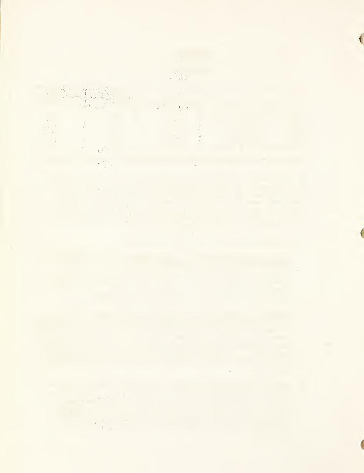
Fig. 14 Area Before Banksloping
Fig. 1.5 Banksloping Completed
Fig. 16 Rood Maintenance Section Before Test
Fig. 17 Road Maintenance Section After Test
Fig, 18 Road Maintenance - Dip Construction BeforeTest
Fig. 19 Road Maintenance - Dip Construction AfterTest


Tables and Figures (cont .
)
Page
Tig, 2C AoW. Bulldozer 54
Fig. 21 Test Area After Dozer Operation 55
}
—Y—

1
%

INTRODUCTION
The grader test described in this report is the resultof an effort on the part of the Division of Engineering to deter-mine the adequacy of commercial units offered on bid invitationto perform in accordance with the rigid requirements of the field.This report is on one unit of the Motor Grader Test Project con-ducted on the San Bernardino National Forest, January 23 to
March 15, 1950.
Originally scheduled for two units, the project x^as ex-panded at the request of manufacturers to include five companiesand five graders ranging from the 22,000 lb. to the 27,000 lb.
classes.
This is one of the individual reports prepared for each ofthe five graders tested. The results of the entire test projectare summarized in a composite In-Service, Confidential reportwhich includes a more general analysis and encompasses a widerscope in objectives.
The actual field testing of the graders i jas divided intotwo major sections (l) physical characteristics, and (2) fieldperformance.
The first section, referred to as the "flat land" test,consists essentially of observations as to physical design char-acteristics. This includes such items as clearances, blademaneuverability, turning radius, observations on operationalfeatures, visibility, operation of controls, and other such dataas would be apparent from a detailed inspection of the machine.
The second section consists of a series of field tests de-signed to simulate the various field operations normally encoun-tered in routine truck trail maintenance on the National Forests.Such operations as bank sloping, drainage dip construction, three-pass road maintenance, finish grading and several others are in-cluded to establish the field operation characteristics of thegrader tested.
Every effort has been made to assure comparable test con-ditions for all graders. Standard procedures were devised, quan-tities and distances measured, and particular attention paid to
soil conditions. Operators were given an instruction period priorto test and allowed to use the machine until such time as theywere considered competent by company representatives or, in theirabsence, road foremen skilled in the use of patrol graders.Company representatives x^ere encouraged to request re-runs wherethey felt conditions adverse or their machine capable of betterperformance.
f
-1-

..
'
..
' f: ,.V
.
'
'
'
. .
%
%

AUSTIN WESTERN 99-H GRADER
The grader furnished for the test was a Model 99-H manufactured bythe Austin Western Company of Aurora, Illinois* The unit was ratedheavy class, with ell-wheel drive and steer, and had hydraulic controlthroughout® It was equipped with low pressure tires, cab, scarifierand 13-foot blade. The grader was powered by a 7*> horsepower ZoH.C*UD-14A diesel engine#
-2 -
.
$
'
• l1
. .
.
•’ ' '..
• :;
.
. .• ,y_ .
.
. .• :
ft
*

DESCRIPTION OF TESTS
Section 1
Flat Land Tests
The first ohase of the '’flat land” test was the obtaining ofdata covering weights? dimensions, clearances, engine data, fuel re-quirements, and the other facts concerning the machine as usuallygiven on manufacturers’ specification sheets. Data taken from spec-ification sheets and from the inspections are tabulated for comparisonand shown as columns 1 and 2 of Table 1, Test Results Section of thereport. In most cases the data agreed with that of the manufacturerbut in a few instances notable variations were obtained.
The second phase of the "flat Land” tests consisted of anaopraisal of the other physical characteristics of the machine as
applied to its various functions. The following tests were performed
:
I. BLADE OPERATION
The purpose of this test was to determine the maneuverabilityof the blade and time required for movement from one positionto another.
Equipment used consisted of protractor, tape, plumb bob, stopwatch, straight edge, still and movie cameras.
The machine was set on a flat concrete slab. Throe referencelines were established; one at the machine fore and aft centerline; and one on each side of center, running from the inside ofthe front tires to the inside of the rear tires. All measure-ments taken were from these reference lines. Center position ofthe blade was established as that condition at which, with theblade touching the slab, the blade and circle were centered withthe machine. Normal position of the blade was established asthat position of the blade in which the machine could operatemost advantageously with no change in lift arms or linkage. Onecycle of blade circle operation i\ras defined as 360° in the caseof machines with full revolving blade, or in case of machinesnot full revolving the maximum degrees of turn of the bladebetween obstructions.
A. Operat ion of Circle. Measurements of time and angle ofcycle were taken. Observations were made regarding possi-bility of damage to parts of the machine by operation ofthe blade.
B. Locking Devices. Observations regarding the orcsence orabsence of circle locking devices, location, and whether ornot they could bo considered positive were recorded.
-3-

...
:• •
.
-
-
...
—
"r.
,'i
,
'
*

C. Bank Sloping Positions. Starting from centered and normaloperating position, the blade was moved to maximum banksloping angle without moldboard shift. Height of blade tipabove ground, bank slope angle, position of heel of bladeon ground with resooct to the tire reference line, and timeto shift to this position were recorded.
The moldboard was then shifted for maximum reach and theblade was set at l-g-sl, Isl, 3/4? 1? lb 1 and l/4?l banksloping positions. Height of tip of the blade above groundand position of heel of the blade with respect to the tirereference line were recorded. The time required to shiftfrom blade centered, normal operating position to the max-imum bank sloping angle was recorded. Still pictures ofeach bank slope position were taken.
D. Side Shift. The distance the blade could bo moved to rightand left of centered position, with and without manual mold-board shifting, was measured. The time required for eachoperation was also recorded. In all cases distances woremeasured with the cutting edge of the blade resting on theconcrete slab. The crew to shift the moldboard manuallywas limited to tho operator and one helper.
E. Blade Lift. With linkage sot for normal operation position,measurements were made and time recorded for movement of theblade from ground level to maximum lift position, end alsomaximum depth below ground, using a pit for this purpose.The number of holes on lift links and the distance ofpossible adjustment was recorded.
Starting with blade and circle in center position and atright angles to center line of machine the maximum bladelift angle, both right and left, was measured. Links wereadjusted as necessary but the blade was not rotated on thecircle for this operation.
The height of the lowest point of the circle with theblade at ground level xns measured.
\
F. Blade Reverse. Ability to reverse the blade was recorded.This tost concictod of setting the blade at 45° for cast-ing material to the right, then turning blade for backingup, so as to continue casting material in the same direction.
G. Pitch Pos itions. Information obtained on pitch positions wasas follows - number of notches, total adjustment distances andthe degrees from the vertical both plus (top ahead of bottom),and minus (top behind bottom.)


H • Visibility. With the blade centered and at 45°, in both rightand left positions, visibility of blade and front wheels was
appraised from still photos taken from normal sitting position,
showing view to right, left, and straight ahead. This -procedure
was repeated for visibility from a standing position.
Rear view visibility was also noted, with still pictures recordingactual views.
II. WHEEL LEAN
The purpose of the test was to determine the degree to whichthe wheels could be leaned for turning and for resistance to sidethrust in operation..
The degrees of lean, both left and right, were recorded, andstill shots wore taken showing angle as indicated by large pro-tractor.
III . GRADER GROUND CLEARANCE
The purpose was to determine ability of the grader to clearwindrows, rock and obstacles which might bo encountered eitherin forward or reverse operation.
With wheels Jr. a vertical position measurements were takenbetween lowest projections ana the ground, behind the blade,and ahead of blade, the latter being limited to 8 inches oneither side of center of the front axle. Particular attentionwas do id to ti.10 possibility of damage to st eering geometry if it
was the lowest projection.
With wheels at maximum loan, measurements were taken in thesame manner ,.
IV . WIDTH OF PROMT TREAD
Tc determine tread width of graders equipped with oversizetires in front, measurements were taken from center to centerof tires
;at point of ground contact,
V . SERVICING REQUIRMEHTG
.
The object of those observations was to determine the timeconsumed and materials necessary in servicing the equipment.
The number of grease fitting,s needing daily and weekly ser-vice were counted, and time for each service was recorded byequipment service men. Also recorded was the personnel neces-sary to do a grease job, lubricants and fuel used and typesrecommended by the manufacturers.
- 5-
s
I
VI TIRES AND RIMS
To determine adequacy and safety of this equipment, data wererecorded regarding ply, size, number, and manufacturer of tires;
type of rim and rim association number. At the end of the test,
cuts, breaks and wear were recorded, giving reasons when possible.Still pictures were taken to show condition of tires.
VII. TANK CAPACITY
The purpose of this test was to determine ability of thegrader to operate for one 8-hour shift with out requiringadditional fuel
,
Information recorded included factory specification on con-sumption, factory specification on tank capacity, hourme torcheck, amount of fuel supplied, and whether or not cigar hoursoperation was obtained from a full tank.
VIII. REMOVAL 0? vLbDCWS, DOORS AND CAR
The object was to determine the case with which doors,windows (windshield) and cab could be removed ,
The test consisted of determining if windows , doors and. cabwere designed for removal., and estimating the tine necessary foreach oeeratior., The major portion of data were obtained fromFores c Service shop personnel and manufacturers,,
IZ, LTGIITS
The purpose of this tost was to determine the adequacy oflights for night operation and. travel.
Intensity of the lights was measured by a Weston meter ata distance of inroe feet. The source of electricity; whethergonoratoi , battery or magneto, was recorded. The location of lights,provision for adjustment, cud adequacy of protection were noted,
X. EMC. .TIE STARTING
The purpose of these observations was to determine theability of ino engine to start under field conditions.
Time for at least four different scores was determined bya stop watch. Temperature, humidity, whether the engine was hotor cold, type of starting and factory recommended sequence wererecorded .

... .. ...
.

XI OPERATION OF CONTROLS
The purpose of this test was to determine the adequacy of
grader controls.
Information obtained included accessibility* response*
ability to vary speed of control action, operation of any two
controls at one time, and ease of gear shifting.,
XII. TURNING RADIUS
It was desired f,l) to determine the minimum c trait in whichthe grad 0.1 could turn, both right and left
, and the road widthnecessary be do so, and (2) to determine the ability of the graderto turn by baching around in confined, areas
-
(i', The grader was turned "o auban, and driver to realty c be
a 360' : circle, :u b'fh r ity t red left direction. The
average di amocer access the inside acks was determinedby r a v:\e3 uf cross- dicimo ter measurenients from which the
rod..:' were computed,
suo.ov.c, set of rcusuromey.ah ii.'. ti.io burning proceroad width necessary forFig . 2 fo: sketch, j
'a, bjali'iy. a turr.r.T' on a mountain road, wasji. a novel • ran w ch cacjj.y, The road width•ii\3 12 feet, tapering to 30 feet at a distance ofThe- lb-foot *ec lion extended for a dist.anoo of
.i ~jC'\ :• an-,
sly c o n ed .
c.npi cnob •
2 5 fue T>
nts v.*c.s l-dci across the tracksas. and the average taken as thet-ro .riniiriuri burr. (Refer to
Operacoi v-. were allowed fo practice on the site so thatonly mcnouverab slimy ot too machine was reflected, in the
tbSofl
The object was to eater bn- area, turn around with theminimum number oi bacoups, and drive out, keeping within,
perpendicular limits as designated by the sketched lines.L second met of linos was drawn with a 12-foot road and35- form turnout., depurate tests were conducted and re-sults recoiled for the 3’> -foot and the 35-fcot width sec-tions (Refer to Fig. 2 for sketch, i
7 -


* >
R H.
V
/ /
,4 .
1 R.F. \
\ L.R
\ V\
\ \
XL.R
"v
\
L.H.
\ v\ \
\
I \ DRADIUS _
; _ RoadI DtT
/ / /
/ /
/ R.f?v
RR'.F.
\
Turk] ins Radius Test
.
r“»r t c>
Tu R M Around Te.st


XIII BRAKE TEST
The purpose of this test was to determine the ability of the
brakes to stop the grader on steep grades and highways.
(a) A hill was stripped of brush and prepared to a compactsurface, with grades up to 49$. Graders were required to bestopped by foot brakes and emergency brakes on the steepestpart of the hill. Actual roll forward and backward afterbrakes were applied was measured. Maximum grade on whichbrakes would hold, both uphill and downhill, was recorded.
Further information noted on both foot brake and parkingbrake was - location of drums as to 2-wheel, 4-wheel or
driveshaft; whether mechanical, hydraulic or electric;provision for holding, and ease of adjustment.
(b) As an additional check on braking ability of the grader,brake tests wore made on level pavement, using the AAA braketester, (Refer Fig. 1 Appendix.) The grader was paced bya car to determine speed of travel, and braking distances forthroe runs were averaged.
XIV. WALK IMG TEST
j
This test was divided into two parts, the first conductedon a paved highway and the second on a truck trail.
£l. The object in conducting this test was to determinethe speed with which the grader could safely travel the high-ways .
The test was conducted over a measured course, startingfrom the Triangle Gravel Pit scales, where the official weightswere determined, and terminated at the campground at Devil'sCanyon, a distance of 6,1 miles. Time was recorded by a stopwatch. Machines were run at governed engine speed. See Fig. 3for map of route,
#2 . The purpose of this tost was to determine the abilityof the grader to safely travel a measured truck trail whichwould tax the maneuverability of the grader on curves, as wellas the maximum power of the engine.
The course started at the Bailey Canyon gate, upgrade to thesaddle at the junction of Devil's Canyon truck trail, thencedowngrade to Devil’s Canyon gate, a distance of 3.65 miles.
Data recorded were time for uphill and downhill trips, grades,and road condition. See Fig. 3 for map of route.
ty
j-8-

.
. :
.•
'
'
.
. .. V'
•• vr/- :
'
, ...
'
-

>
V
H laWLA^D
.4- Ml. &ya
Ml. S
TOTAL- Ml LBS 3.03AVERAGE GRADE I 0.36*7®
| A5 MILE5 UPGK.ADEXAV- 11.83 /o
2..30 MILES DOWNGRADE (AV. <9.69 %1 CURVE LESS TMAKi 35 1 LAuu5
DEVI AS CANYONGATE0.3 MILE
B>Ailby Canyon Walking Test -trial 2.
* '! DEVILS CLAN YoNlCAMPGROUNDG.l ml
•oAT
*<VjHi
N
i
Mail boxes*D" 4, *2 Ml.
%y4 .
ALUi4'
Mj
-?C*L
(POST)A Rock co.
VV; l.'ZML 'V
B" ISMI.
2.7M1.
*\J s\
»0 *4
Triangle Rock To Devils canyonSpeed Test
Trial \
AVE .
Fie.

f
V

XV. BREAKDOWNS
While not in the form of a test, an informational list wasset up as follows; breakdowns, description of breakdowns, photo-graphic record of each, cause (whether design weakness cr accident),facilities to repair, availability of parts, and time lost.
XVI. FINAL CHECK
After the grader had been put through the field tests ofSection 2, it was returned to the "flat land" slab, thoroughlycleaned and carefully examined for all cracks, breaks andbends which were not evident as definite breakdowns. Eachdefect was described and photographed for permanent record.Pictures were taken of the tires to record wear and injuries.
.
:
' '
.
'
'
'
, .:
'
.

DESCRIPTION OP TESTS
Section 2
Field Test
Field performance tests were as follows:
I, SLIDE REMOVAL
The purpose of the test was to observe the ability of gradersto surmount obstacles, such as slides commonly encountered inroad maintenance#
Slides occur frequently on roads in steep terrain. If themotor patrol can handle the occasional slide and thus save im-porting a bulldozer, a considerable saving will result^
A slide of designed shape comprising approximately 125 cubicyards was built by a tractor, avoiding compaction of materialas much as possible. Dirt was allowed to accumulate oil the down-grade (or approach) side at its natural angle of repose, whichwas approximately 10%, boundaries were established by means ofstakes simulating a perpendicular bank beyond which a wheel underpower was not permitted* Refer to Fig. 4*
3Pig.- 4 * Test Slide
-lO

'r
'V. <>
t ®‘4 ' 07'^’,
<v «
?•> • 4
'A
5f:fr ••* (. fMtUr r
* '•/•;
•/ /. /
'I
-,
’ V V(b..:<r
,
. /• f
T .
hi. i:
;*• * i-' *%; T
g ..
•X 7 (j\. „
nx .jv/ * ' JTo -
' •
fV| I
' ; /
Xi
V i
’>’
\
.7'.
f *
Of
*V
The test machine was required to climb over the slide in order
to be in a position to attack the dirt removal task on a downhillbasis.
Test conditions were recorded by still shots and progress duringthe test by movies. Information recorded consisted of - size ofslide and time required to c limb over, operator sequence and methodof attack.
Since more than one machine was tested at this site, after themachine surmounted the slide, no further dirt was removed. Theslide was then reconstructed to original size and shape.
II. IN-CURVE
The purpose of the test was to measure the ability of the graderto maneuver on a short radius in-curve.
Conditions of the test; The situation simulated was the wash-out on a canyon crossing, the outer portion of the road being complete-ly gone and the inner portion defined by vertical walls. It wasrequired that the grader was required to travel the curve, using theminimum road width. See Fig. 5 for details and sketch of test layout.
This condition results frequently after severe storms in ruggedcountry. Ability of a particular machine to handle these situationswould save much expense in importing a bull dozer for the operation.
Performance was recorded by use of movies and still 'pictures.The maximum width of road needed as measured from the inside tiretrack to the simulated perpendicular wall was recorded.
Since ability of operator affects the time required, re-runswore allowed if operator thought he could improve the performance.Regardless of time consumed, operator ability was evaluated in anattempt to determine machine performance, analyzing reasons for such.
III. GRADING OF DIPS
The life and useability of a road depends to a considerable extentupon the proper functioning of the drainage system. Grading of dipsis one of the most important operations of a grader on roads whereintercepting drainage dips arc used.

'
1>
i

SIMULATED CONDITION F I c~.
/
* X( /
-j y
VL&J N _i
I ncurve
l,x‘ ^
' ~~-tfcT-
/ / /. -O-. .''
'


The construction and maintenance of dips involves several cfthe functioning parts of a motor patrol. A dip consists of aninvolute curve, descending on an increasing vertical curve with anincreasing outslope, until the depression if reached. The bottomof this depression is placed at an angle of 45 degrees to the centerline of the road. The profile then rises rapidly for a distance of
15 feet to a summit, also at an angle of 45 degrees to the road centerline, then returns to the normal road profile in a second distanceof 15 feet. Refer to Fig. 6 for sketch.
To construct or maintain a dip requires blade manipulation bothabove and below the plane of the base of the grader wheels. It
also .requires blade manipulation in a vertical plane to take careof the increasing outslope and also in a horizontal plane to takecare of the changing angle of the outslope. This second manipula-tion is usually handled by steering.
A. New Construction. Conditions: Operator practiced with graderuntil he was familiar with operation of machine and also thetechnique of tip construction. Stakes were set indicatingbeginning of cut, bottom of dip on a 45° angle and terminationof berm. Operator was allowed as many passes as was necessaryto construct to the oroper standard as required by road foreman,who w-as judging this test.
Still pictures were taken at side before operation and after,and movies taken during operation for the purpose of analyzingmaneuverability of the blade. Information recorded was -
location, material, difficulties, operational sequence, tine,soil moisture and foreman's rating of completed job.
B. Maintenance of Dips . Existing dips were selected which werein need of reshaping and sluff removal. Motion pictures ofoperation were taken for analyzing blade response to controlsand the ability of the blade to follow an existing profile. Atthe same time observations were made to determine if the liftmechanism range was adequate for below grade extension whilepossessing sufficient lift above grade to complete the operation.
Still pictures before and after were taken. Location, grade,road width, material, difficulties and reasons, operationalsequence, time, soil moisture, blade response and control wererecorded.
-12-

• t
'
.M
I
’
5 ...
. .
>!•

I NITE.RCEPTI K16 DIP
XL'''
l '' {/H .
‘
:
*4•:fy ,
>.
I \ £ Tp. •
i SiJ \ k'Sib, 4‘-
.. %4 4. ',..4 O).
. -‘i ;V; v V/ • A'
' %vv /•>;,
M 4'' t
.
, vvV F%,N/k, ^ ^ h
4 -
.^4

IV. DITCHING
The purpose of this tost was to determine the ability ofthe machine to function under difficult conditions involvingextremely heavy work. The operation involved the use of theblade and scarifier in cutting dirt and rock and in removinglarge boulders by undercutting and pushing, and the bladeand blade control mechanism in finish grading at the end ofthe operation. It also tested the ability of the machine to
provide traction while working on a slope and pushing materialuphill. The general toughness of the whole operation was atest of the stamina of the machine.
An area, 200 feet long and 32 feet wide, which was high inrock and boulder content, was selected. Test consisted ofdigging a 200-foot ditch on a 6% slope similar to shoulderconstruction on one side of a highway. The vertical depth ofthe ditch was 3 feet with cut bank on a 3/4-to-l slope. Thedistance from the ditch line to the shoulder was 16 feet andconstructed on approximately a 4 ; 1 slope. All material wasside cast beyond the 16 foot width, or beyond the 200 footend limits. Operators were allowed to use blade and scarifier.
Information obtained was - location, grade, side slope,material, depth, xvidth, distance, time, and appearance of thefinished job. Still pictures before and after were taken, alsomovies of interesting or unusual incidents.
V. SCARIFYING
The purpose of the test was to determine the ability of thegrader to loosen imbedded rock and to do normal scarifying work.Essentially, the test was for the purpose of bringing out thestructural ability of the unit to do this kind of work undersevere conditions.
This operation is very important. It is required in main-taining road material or a travelnble surface on all roads, andis particularly needed after heavy storms.
After completion of the rough shaping of the ditch (TestNo. IV), the inside slope area containing numerous imbeddedrocks, was used for this test. Information recorded was -
location, grade, width of scarifier swath, material, soilmoisture, number of teeth used, depth scarified, time, oper-ational sequence, operator reaction, failures, and time requiredto install teeth for operation. Time element was not importantexcept to require operation at a reasonable speed. Still shots,before and after, and movies were taken.
-13-

.
'
.
•
t : .
.
c
<
"
'
.
.
(

VI. BAM SLOPING
The purpose of this tost was to determine the ability of
the graders to side-slope banks at any required slope fromly-to-1 to l/4-to-l.
This operation involved the use and adjustment of the con-trol arms, the use of the circle, and general manipulation ofthe circle and arms assembly.
Sections of roads 500 geet long were selected in whichbanlcs at least 10 feet high existed, and included in-curves,out-curves and tangents.
Information recorded was - location, grade, material, dis-tance, time, maximum height of cut, analysis of finished job,
difficulties, and operator reaction. Still shots were takedof grader in oosition, and of road before, during, and after.Short movie sequences were taken to record the operation.
Bank sloping on Forest -Service work is done largely on re-construction or heavy maintenance work. Although it does notinvolve a very high percentage of total volume, the occasionsof use require a highly maneuverable blade assembly.
VII. DRIFTING
The purpose of this test was to determine the ability ofthe grader to end-haul material. The operation involves thesize, design and pitch of the blade controls.
Drifting is required continually in normal maintenance oper-ations to remove slides, fill washouts, and restore surfacing.
Material for drifting operation was taken from a low cutbank extending 100 feet, moved across a 25-foot area, andplaced in an area 75 feet long and 12 feet wide, to a depth of .6 ofa foot, forming a finished road bed. At the end of each pass,grader with blade lifted returned to the far end of cut banksection.
Data collected included - location, distance, grade, material,angle of blade, pitch of blade, estimated yardage, material lostor picked, up enroute, time, and operator reaction.
Time element was very important in this test since it reflectedbalance of power and blade size, ease and dexterity of blademovement and time consumed in shifting gears.
Still pictures were taken to show before and after operation,also movies to show dirt movement on blade, and amount of materialbeing moved.
-14-

: , :
s r
<
(

) VIII.
.IX.
%
HORIZONTAL MOVEMENT OF WINDROW
The purpose of this test was to determine tho ability ofthe machine to move a windrow of dirt laterally. It involvedthe size, shape and pitch of the blade, the tractive abilityof the machine, and the functioning of the blade control mechanism.
This operation is used in all road mix oiling work and inconstruction of roads on flat terrain.
A section of road 1300 feet long, with an average grade of
9%, was designated as the test area. A large windrow xrnxs
formed on one side of the road, and measurements made fromestablished reference points. The grader in four passes wasrequired to move as much material as possible to the oppositeside of tho road, forming a more or less uniform windrow.Lateral movement of dirt was determined by measurements takenat the reference points, and total yardage figured from crosssection measurements taken every 100 feet; The elapsed time forthe operation was recorded.
SHAPING BERMS
The purpose of the test was to determine ability of thegrader to form a berm 18" high with side slopes l-g-rl. This
operation is of great importance on all roads using berms as
a drainage control feature. This includes most of the roadmileage in the California Region.
A section of road between 300 and 500 feet in length wasselected and material in existing berm was spread over theroad bod. Three passes were then made, ending up with thematerial forming a uniform berm on the outer edge of road.
Information recorded was - location, grade, material, dis-tance and time. Still shots before, during, and after operationwere taken.
HILL CLIMB
Tho purpose of the test was to determine the ability of themachine to climb grades up to 50% in both forward and reversegears
.
The site selected for the test had a runway with an overalllength of 300 feet, which started level and gradually sloped upto a maximum of 49$. Graders were required to climb uphill for-ward and uphill backward, recording percent of grade at the for-ward point of stalling, if any. The decomposed granite surfaceof tho hill was prepared before each run so no loose materialhindered the test.
4-15-
.

II. UPHILL GRAD IMG
XII.
XIII.
The purpose was to determine the ability of the machine to
climb uphill and do normal grading at the same time.
Road sections, 500 feet long, in which grades from 10 to
21% existed, wore selected. One pass uphill was made.
Information noted was - location, material, soil moisture)grade, time, tendency of machine to drift under load, andappraisal by road foreman as to effectiveness of the work.Still shots before and after, and movies during operationwere taken.
ROAD GRADING
The purpose of the tost was two-fold; first, to acquaintoperator with the three-pass operation in road maintenanceand, second, to provide an apportunity for observers to analyzethe performance of each grader on a short section of road.
Sections of road 500 foot long were selected which were inneed of maintenance, and which included in-curves, out-curves,turnouts and dips.
Operation consisted of three passes: cleaning the ditch ofstuff, spreading and. removing rocks and smoothing.
Information recorded was -- location, grade, road conditionas to ruts, amount of stuff, material, soil moisture, distance,time, maneuverability
,difficulties, appearance of finished job,
and operator’s reaction. Still shots before, during, and afteroperation were taken.
ROAD MAINTENANCE - LONG SECTION
The purpose of this test was to determine the overall abilityof the grader to do all of the important functions of a roadmaintenance job. These operations include slide and sluff re-moval, dip maintenance, normal and fine grading, born construc-tion, and drifting. Bank sloping was not included. Operationwas up and down hill and around minimum radius curves (under
35 feet), and involved the uso of all grader controls.
This work is the primary purpose for which motor patrols arcpurchased and constitutes the larger portion of their use.
4
-16-


V)
Sections of truck trail with grades up to 20% and needingmaintenance work, two miles in length, were marked by means offlags. Picture stations were marked for the purpose of beforeand after photographic records which would depict the differentfunctions common to the operations of rock removal, sluff re-moval, dip cleaning and shaping, and fine grading. Three passeswere required.
Information recorded was - location, material, distance,time, amount of work to do in rock, sluff removal, number ofdips to shape, and number of minimum curves,
Aopearance of the finished job was appraised by engineers androad foremen.
Fine Grading
On the two mile maintenance section an area suitable forfine grading was selected where no appreciable amount, of rockwas present.
Results of the operation were carefully analyzed for absolutecontrol of the blade, since this test was considered as ameasure of the ability of the grader to handle surfacingoperations.
Still pictures before and after viere taken to indicate thedegree of improvement resulting from the operation.
-17-
,
—
{
,
<

TEST RESULTS & COMPARATIVE DATA
To facilitate comparison and to conveniently tabulate thevarious date obtained from the test, Table I, Comparative Data,
has been prepared.
The date recorded in column one (l) are taken from the
manufacturers' published specification sheet and cover the stan-dard production model only.
In column two (2), are summarized the data taken from the"flat laud" and "field test" sections of the report. Discrepanciesin this column from the manufacturers ' ratings as shown in columnone (l) may bo attributed to definition or deviation from standardon the test machine. Where considered necessary, deviations arediscussed under the Discussion of Test Results.
In columns throe (3) and four (4 ) are the data of othergraders tested in this class. The intent here is to show the max-imum and minimum of the other data collected. It should be notedthat the maximum as shown does not necessarily infer the best,particularly where time is involved. Constant appraisal of theitem under consideration will be necessary to properly evaluatethe tabulated results.
-18-

.

TABLE I
COMPARATIVE DATA
Flatland Tests
Item
Mfr . Spec. iA.W. 99-H Other Graders Testedsta. Machine Test Mach. Maximum Minimal:!.
M L (i) ( 3 ) (4)
'EIGHTWeight, total 22 ,100 22,560 27,950 2u f SG0
Weight on front, "/this. 9.790 9,350 8,630 n3HWeight on rear vsheele 12,710 13,150 19,310 17,1.50Blade pressure 1 .8,500 18,920 15 j 4 oO — — i S'-
'
Scarifier pr assure 11,100 10 ,46C 9,970 8 ,2'iC
DIMENS LON'S
Length overall 24>~5' j 24 r -3" 27 ? -fT’ 2 4 ? -0 :
Width overall 7?..] 0-3/4" 75 -IO-3/4 " 8 5-0" 7 v -7 ;/ O'
Height overall w/cab 105-1" 10 »-l" 105-8" O ?/ J
/.L
Height overall w/cut cab 8«»8 ; ’ 8 ? -8" 8°»0 S! 6'< ~ld :
Height inside cab — 73-1” n crA-?/t 3 69 -
WheelbaseTread, front, c, to c.
18 »« 8 " 18 ’-8" 195-7" l85-9«
of tires. 7915” r-iieOO7
or.
Tread, rear, c. to c.
of tires. --- 79^*' 82 " V8r" 1
SPEEDSMin. forward raph 1,7 2.6 E v
« •
Max, forward mph 15.0 ~ ~~ 25.2 16,83Min. reverse mph 1<74 — 3,7 2 . /
Max. reverse mph 5,87 —
.
6,13 4,1Number forward 6 6 8
Number reverse 2 2 3 0
ENGINEBrake HP 76 76 113 lOuNo. of cylinders 4 4 6 4
RPM - Governed max. ooi
—
1
1,555 1,990 1,660
CAPACITIESFuel tank (gals.) 58 58 60 45Cooling system, (gals.) 14 14 20 6-1-
Crankcase (qts.) 16 16 23 16
TIRESSize, front 14.00-20 14.00-20 14.00-24 13.00-24Size, rear 14.00-20 14.00-20 14.00-24 13.00-24Ply 14 14 12 g
•19-

(
f

TABLE I (Continued)
COMPARATIVE DATA
Flatland Tests
Mth u Spec. A.W. 99-n Orher n,-a 5 '*£,fr
‘•’ 3 '”(•
»C*
|
Std Machine Test Mach.1Maxiau ra
[Min. .mu.
a
Items i a; ( 2 ) !i3; M .
BLADE ASSEMBJJ
w? dkb , tli Lokaos 3 'L 5
Blade side shift • l-I •
v* > o=Lf
.-v- x !a ^ .I3^;22-|"x5/4 " 12 "x2 h fpr•16 I'J'v-'JCH'
;Mfr, Rating) 7 i;
Right blade side shi.fr
power oper <* £
from center pusiricn(circle shift/
' circle shift & lint
19" - 05';
adj , )— ir- y'lt 22“ :
( circle , links £ mold-board adj,) 5T '
5 L
Blade lift above ground.
Sect, 1 - Tes-c E l6 : - lb" )rir:•^2 14 -"/4 ,f
Blade depth below groundSect., 1 ~ Tesu E
Pitch positions ~ number
— 10/ :
5 c
for tilting — 6 13 7
Max-, shoulder reachBank slope angle (test
8 9-i-** 88/'
63°
87" 76#
51°jondii t ions 1 -0- 3 > 7 4C
Circle dinmate
v
Degree turn blade ///scar
62* 62" ^' r- 4.
.
teeth 320^ 320° 0
9 6w
Degree turn w, o scarifierteeth 320° 360“ ^60°
Lifting speed (Approx,
*
2*. 37 ''/sec. ?. olG"/beCr 0 93"/ sec.
SCARIFIER - V TYPEWeight 1,300 1,300 1,475 1,314Swath width 46" 46" 46" 46"
Teeth number 11 11 11 O/
Teeth size l"x3" l"x3" l"x3»Pitch positions — 1 5 1
Pressure max. — 10,460 9 S ?70 8,200
WHEEL LEANMax. L 0° 0° IT3/Max. R 0° 0° 2l|° 11°
20


TABLE X (Continued)#
COMPARATIVE DATA
Flatland Tests
Mfr. Spec. A.W. 99-H Other Graders Tested
ItemsStd. Machine
( 1 )
Test Mach.
( 2 )
Maximum
(3)
Minimum
1 .(4)
GROUND CLEARANCEBehind blade ) 13” 13§" 10-3/8 ”
Front blade ) Wheels Vert.- — 14” 27e" 19-3/8”Behind blade )Wheels Max. — -— 13|” 10- 3/8”
Front blade ) lean — — 27” 19”
TURNINGTurning radius (Insidewheel) R 30 *
-
10” 22 «--J" 27 » — 9*» 21 »-10”
Turning radius (Insidewheel) L mm mom* 229-9” 2 9»-3" 26»-9”
Turn, radius - Av. insidewheel * av. road width 30 »
-
6” 41 9 -2^” 389 -5 ”
Road width to turn R — - 8 »-0” 13 »-10 ” 12 »-8 ”
Road width to turn L — 8 »-2” 13»-4” 129-9”
•21-

;
a
.
'
•.
•

TABT.E I (Continued)
COMPARATIVE DATA
Field Tests
Mfr. Spec. A.W. 99-H Other Graders Tested
ItemsStd. Machine
(i)
Test Mach.
( 2 )
Maximum
(3)
Minimum(4)
HOAD WIDTH FOR TURNING -
NUMBER OF BACKUPS
35 Foot Road 2 4 2
30 Foot Road — 3 8 5
DIP CONSTRUCTION (Time) 25 M. 23 S. 27M.O S. 14 M. 36 S.
DITCH CONSTRUCTION (Time) 8 H. 58 M. 11 H. 35 M. 8 H. 20 M.
DRIFTING (Cu. Yds. /min.) — 1.1 1.29 0.97
MOVE WINDROW (Cu. Yds.Feet/min.) — 85.5 149.0 96.5
SLIDE (Climb over rain.) 50 M. 0 S. 41 M. 0 S. 15 M. 57 S.
INSIDE CURVERoad width needed - Av.
L & R ... 9 i9’-ni" 19 «
-
6“
ROAD MAINTENANCE (Miles/Hr.) 0.48 0.635 0.51
BRAKE TEST - © 18 mph —— -
.
15’ 38 ? 19’Cal. Veh. Code Min. 30
»
WALKING TEST (1)
Paved highway 1.2 Mies 15.8 mph 24.6 mph 18,3 mphDirt highway 1*9 Miles 12.35 " 17.54 « 14.07 "
Total highway D.l Miles 14.5 " 19.94 " 17.7 "
WALKING TEST (2)
Uphill T.T. 1 • 35 Mies 6.11 mph 6.56 mph 4.49 mphDownhill T.T. 2 .3 Miles 9.13 " 16.24 » 9.69 "
Total T.T. 3 .65 Miles 7.70 " 9.98 " 8.27 "
-22 -

•
•
: '
.
.
<
• •
>
.
•
(O
(
(
DISCUSSION OF RESULTS
Flatland Tests
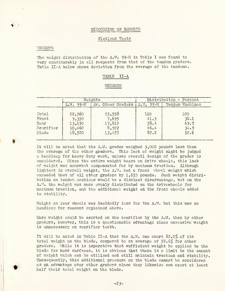
WEIGHTS
The weight distribution of the A.W. 99-H in Table I was found to
vary considerably in all respects from that of the tandem graders.
Table II -A below shows deviation from the average of the tandems.
TABLE II-A
WEIGHTS
»
Weights Distribution - PercentA.W. 99-H Av. Other Graders A.W. 99-H Tandem Machines
Total 22,560 25,558 100 100Front 9,350 7,695 41.5 30.1Rear 13,150 17,812 58.4 69.7Scarifier 10,460 8,922 46.4 34.9Blade 18,520 13,^57 82.2 52.6
It will be noted that the A.W. grader weighed 3,000 pounds less thanthe average of the other graders. This lack of weight might be judgeda handicap for heavy duty work, unless overall design of the grader is
considered. Since the entire weight bears on drive wheels, this lackof weight was somewhat compensated for by maximum traction. Althoughlightest in overall weight, the A.W. had a front wheel weight whichexceeded that of all other graders by 1,655 pounds. Such weight distri-bution on tandem machines would be a distinct disadvantage, but on theA.W. the weight was more evenly distributed on the drivewheels formaximum traction, and the additional weight on the front wheels addedto stability.
Weight on rear wheels was decidedly less for the A.W. but this was nohandicap for reasons explained above.
More weight could be exerted on the scarifier by the A.W. than by othergraders, however, this is a questionable advantage since excessive weightis unnecessary on scarifier teeth.
It will be noted in Table II-A that the A.W. can exert 82,2/. of itstotal weight on the blade, compared to an average of 52 . 6 /. for othergraders. While it is imperative that sufficient weight be applied to theblade for hard surfaces, it is obvious that there is a limit to the amountof weight which can be utilized and still maintain traction and stability.Consequently, this additional pressure on the blade cannot be consideredas an advantage over other graders since they likewise can exert at leasthalf their total weight on the blade.
-23-

.
,
/
.
:
;
,
.•
;
.
.......'
.
«
<
.
.
.

Proper weight distribution of some graders was questioned several timesduring field tests. After reviewing the weights of all graders, it wasdecided that horsepower was a factor to be considered along with weight.In an effort to analyze the relationship between weight and horsepower,a comparison was made between overall weight and horsepower, and alsobetween drivewheel weight and horsepower. Results are tabulated in
Table II -B.
TABLE II-B
WEIGHT HORSEPOWER RATIOS
A.W. 99-HOther Tandems
Maximum Minimum
Overall Weight 22,560 27,950 25,100Drivewheel Weight 22,560 19,300 17,600Horsepower 76 100 113Total Lbs. / H.P. 296 280 222Drivewheel Lbs. / H.P. 296 193 156
The ratio of drivewheel weight to horsepower for the A.W. was 296 as
compared to a maximum of 19.3 for the tandems. Since the A.W. was allwheel driven, the ratio between overall x'ueight to horsepower was thesame and also the highest. In all of the field operations the A. W,was able to perform with minimum loss of traction or evidence of excessivedrifting.
It was noted that two machines were excessive drifters. Computationsshowed the ratio of overall weight to horsepower of one to be 236 andthe other 222. The ratio of drive wheel weight to horsepower for thesemachines was 165 to 156 respectively.
It is not the intent of this report to determine the ideal weight horse-power ratios, but merely to suggest that this weight power relationshipmay play an important part in the performance of a grader.
DIMENSIONS
Of all the machines tested, the A.W. 99-H had the least overall lengthand wheelbase. This was a distinct advantage to grader maneuverability.The vertical clearance inside cab of the A.W. 99-H of 73^" was aboveaverage when compared with other graders. The minimum cab clearance forthe group was 69" which was considered inadequate. Height with cab andoverall width of the A.W. 99-H was within the range noted for the othergraders. Height without cab was 8 ,! more than any other grader.
Size and weights of the A.W. 99-H frame sections appeared adequate andcomparable to the average of other graders tested.
-24-

' '
•
.
'
..
I
* • • : • — -' •
'
• • !•
. ;v
Q
. .
.
'
'
•: •
. ,
-
•
, , v_
<
SPEEDS#
The A.W. 99-H had six speeds forward and two reverse* Gear reductionwas such as to provide adequate speed and power for all tests exceptthese involving highway travel. Maximum forward speed of 13 mph, whilesufficient for truck trail maintenance, was not thought adequate formoving the grader from job to job. Reverse speeds should be carefullyconsidered as they apply to actual field requirements. Experiencewould indicate a need for a low speed to be used for backing out of
a bad situation, and a much higher speed for backing up rapidly undernormal operation when the blade is empty. Selection of gear reductionin the A.W. were evidently made with this in mind, resulting in a lowreverse speed of 1.7 mph and a high reverse of • 87 mph. When comparedto a machine which has two reverse speeds of 3*4 and 4.6 mph the advant-age of the A.W* is evident.
The comment here applies only to speed and is not intended to coverthe transmission as a mechanism for changing speeds. This is discussedelsewhere in the report.
ENGINE
The A.W* 99-H had an International, four cylinder, four stroke cyclediesel engine with a bore of 4-3/4" , stroke of 6g" , displacement of
460,7 cu. in. and was rated at 76 brake horsepower at a governed speedof 1400 rpm. The engine had a crankcase capacity of 16 qts. and therecommended fuel was commercial die3el. Electric starting was providedwith the engine being started on gasoline and shifted to diesel fuel.
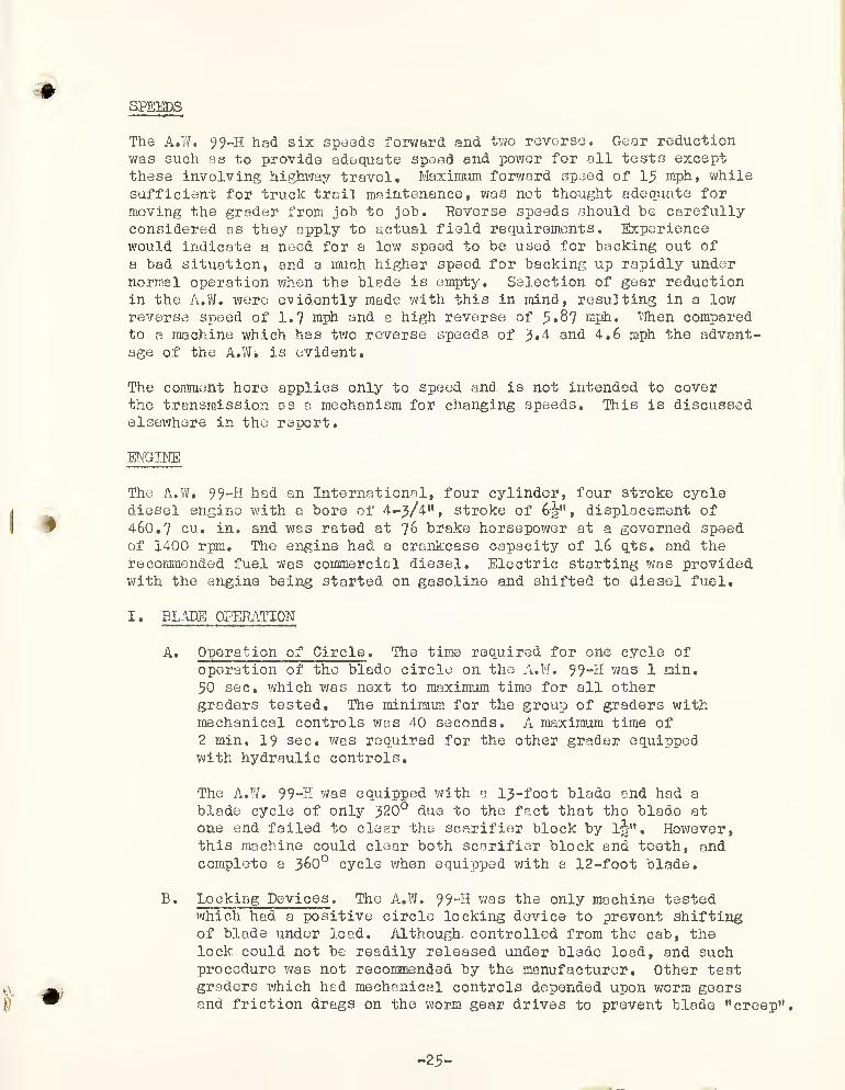
I. BLADE OPERATION
A. Operation of Circle . The time required for one cycle of
operation of the blade circle on the A.W. 99-H was 1 min.
50 sec. which was next to maximum time for all othergraders tested. The minimum for the group of graders withmechanical controls was 40 seconds. A maximum time of2 min, 19 sec. was required for the other grader equippedwith hydraulic controls.
The A.W. 99-H was equipped with a 13-foot blade and had a
blade cycle of only 320° due to the fact that the blade atone end failed to clear the scarifier block by lir". However,this machine could clear both scarifier block and teeth, andcomplete a 36O0 cycle when equipped with a 12-foot blade.
B. Locking Devices . The A.W. 99"H was the only machine testedwhich had a positive circle locking device to prevent shiftingof blade under load. Although, controlled from the cab, thelock could not be readily released under blade load, and suchprocedure was not recommended by the manufacturer. Other testgraders which had mechanical controls depended upon worm gearsand friction drags on the worm gear drives to prevent blade ’’creep"
.
-25-
.
•
'
.
•
'
*
-
c

Although blade "creep** under load h«s been experienced ongraders by the Forest Service in the past, there was noevidence of its existence on mechanically controlledgraders tested. It was concluded by test observersthat means other than that used by the A.W. 99-H to
lock the circle would be desirable. But in all instances,and regardless of locking method used, adequate provision toeliminate blade "creep" must be provided.
C. Bank Sloping Positions . Hie A.W. 99-H, like all othermachines tested, had no special attachments for bank sloping.This unit had the advantage over all other graders tested inits ability to attain bank sloping positions directly fromnormal flat blade position, all controlled from within thecab. Side shift of blade on circle was also cab controlled.This increased blade maneuverability and efficiency sinceit was not necessary to stop the machine and to changelinkage or manually side shift the blade on the circle, as
was normally required for all other graders performing insimilar circumstances.
In this test, the blade on the A.W. could be readilyshifted to all bank sloping positions required.
The following tabulation, Table III, shows the height ofthe blade tip and the position of the heel of the bladefor various bank slope positions, together with maximumand minimum measurements for other machines tested.
-26

(

TABLE III
Bank Slope Blade Positions
Bank ;Other Machines Tested
Slope (AngleT r 1
A.W. 99-H Maximum Minimum
14:1 34°\
Height of tip above ground 32" 63" 32i"*' " heel » 0 0 0
Distance heel inside ref line 0 24*' 0" " outside " " 0 0 0
1:1 43° Height of tip above ground 754” 81 " 49"" heel " " 0 0 0
Distance heel inside ref line 0 loj* 0" " outside " " 0 0 0
3/4:1 33° Height of tip above ground 82j« 112" 84"" " heel » " 0 0 0
Distance heel inside ref line 0 0" " outside " n 6" 0 0
4:1 6 2° Height of tip above ground 114” 123" 84"li " heel " » 0 0 0
Distance heel inside ref line 0 0 0" " outside " " 134" 144" 0
4:1 76° Height of tip above ground 764" 1384" 109"» » heel " " 0 &ir" 0
Distance heel inside ref line 0 0 0" " outside " " 23-3/4" 17j» 12"
-27

c
.
.
'
•
V'
I
"
.
.
.
(1
G

Photographs Fig. 7 and 8 show bank slope angle for 1:1and -ibl slopes.i
Fig. 8. ibl Eank Slope Angle
-28-

,’! = •: :
'
. . c
(
c

£ D, Side Shift ,. With the blade set in center normal operatingposition, it was shifted 19" to the right at ground levelby means of the lift and lateral controls. This was withthe lateral linkage sot for right hand operating position.With the lateral link set for left hand operating position,the blade was shifted an equal distance to the left. Thiscompared with a minimum of l6-|B and a maximum of 25^
B forthe other machines tested.
It should be noted here that although 19” was the maximumsideshift distance for the A.W. 99-H under conditionsstipulated for this phase of the test, an actual additionalsideshift of 38” was readily available through power controlfrom the cab? This grader was the only one tested which hadthis feature.
-29-

''
=: i
.
'
' • ' i*. -.
'.
• :•
-'
'
:
: -
•
.
...
, ,.
,v
5: "
•
1
’
.
:
: ;
..
••: . ;-;j
•
' >.:: *>-'
. . '
.-
' " •... .
;.
' ::
'
•
'
• •

The time for the shift from center position to maximumright and return to center was 42 seconds, as compared
with the minimum of 49 seconds and maximum of 66 seconds
for the other machines. Due to the different distances,
these time figures ’were reduced to shift in inches per
second and are shorn in the following table,
TABLE IV
Blade Side Shift
Other Machines TestedWith Blade Centered on Circle A.W. 99-H Maximum Minimum
Distance Right 19” 25i" l&i"Shift Inches per Second • 91
—
.98 . 63.
The number of linkages for blade control of the A. VI. (and pointsof wear) were at a minimum.
Linkage ball studs were given jjarticular attention on all units todetermine attaching method (welded solid, cast integral with a
relative part, detachable by means of a threaded shank, etc.)
On the A.W. 99~H these studs were integrally attached by welding,wherever possible to do so, thereby keeping wear-points to a
minimum. It appears desirable that these particular parts befirmly attached. Replacement of these parts is usually a minimumrequirement, and experience with the detachable type has indicateddisadvantages which can be overcome by integral attachment.
On the machines tested there were three methods of blade sideshift on circle (1) power ram, (2) unbolting and rebolting bladeon blade beams, and (3) blade slide. Time for blade shifting onmachines where blade was unbolted, shifted and rebolted, averaged
9 minutes 9 seconds. Machines using slide mechanism averagedmore than 20 minutes. Power ram time was loss than 30 seconds.
-}0 -

(

E. Blade Lift . The maximum lift of blade above ground, drop belowground, angle of lift right and left with blade centered, andthe clearance between blade cutting edge and bottom of circleare given in the comparison Table V.
TABLE V
Blade Lift
With Blade in Normal— —
Other Machines TestedOperating Position A.W. 99-H Maximum Minimum
Max. Lift above groundTime for max. liftRate of lift (in. per sec.)
Max. drop below groundClearance blade cutting
edge to circleMax. angle rightMax. angle left
16"
6-3A Sec.
2.37"231"
28|"
8|8A
15 Sec.2 . 18 "
10|"
27-3A"15-b°iio13s
14-3A"7 Sec.
. 98"
5”
24A8°'
8°
) In the above group of operations, with exception of maximumright and left angles, the A.W. 99~H was above average whencompared to the other machines. Total blade lift and lowerrange (controlled wholly from cab) was for this machineas compared to a maximum of 25 - 3A" -for any other grader tested.
-31 -

c
-
..
• .
'

With regard to exception noted for right and left angles f
9 the &?r0 angles recorded were next to the minimum for any
machine tested# It was recognized that the 13 foot blade on this
unit decreased the maximum angles which could have been obtained
with a 12 foot blade. Photograph, Fig. 10, shows blade lift
angle from centered position.
Fig. 10. Blade lift angle from centered position.
Note: The test method and definition of the angles referredto here are explained in the forepart of this reportunder Flatland Tests, Blade Lift.
F. Blade Reverse . This function was accomplished by the A.W. 99-11
without difficulty. However, since the 13 foot blade was notfull revolving, the angle of turn in going from one position to
another was sometimes greater than that of machines having fullrevolving blades. For example when going forward with the bladeset for right hand operation at 45° and casting material to theleft of the machine, the blade had to be turned through 270°
to grade in reverse and cast material to the same side. Formachines having full revolving blade the angle of turn to do
the same work would be only 90°.
•d
-32 -

' C :; ir-- •
, .
'"
-'
''
; •
:• .
• !
:
’:
.
' -•
''
'
’
; : ..
•.'% : : It •
. .-
.. / O- .. .
.
••" -
.
'
-
.
•..
•
"C . V-•
•• :
•
' fi.‘-
'
•
y•
... V. • T
.
:..... .
. ....
;• -
.•
. :
"i-.! , v '
-v ' •• '
.,i
.
• • •
.

tG* Blade Pitch Positions . The comparative table of pitch
positions and angle of pitch is given in Table VI.
TABLE VI
Blade Pitch
Other Machines TestedA.W. 99-H Maximum Minimum
Pitch Forward * 29° 4330 * 27y°
Pitch Rear + 9° - 17 0 * 1 0
Pitch Positions 6 15 7
!
The angle of pitch and number of pitch positions of the
moldboard on the A.W. 99-H were less than that of othergraders tested. Pitch angle range and positions whilecomparatively limited did not present any noticeabledifficulties during the tests.
H. Visibility . Visibility of wheels and blade is of special
) importance in Forest Service operations where steep grades,narrow roads, and short radius curves are prevalent. Noneof the units tested had complete visibility, since all hadmechanisms that partially obstructed the operator’s viewof either blade or wheels. It was the concensus of observersthat the A.W. 99-H rated second best of the five machinestested. Refer to photographs Figs, 11 and 12 for visibilityviews,
H . WHEEL LEAN
The A. W. 99-H does not use leaning wheels. As a means of com-pensating for blade side thrust, the A.W, 99**H employs the useof four wheel drive and front and rear axle steer to positionthe grader to maximum advantage. Tests showed this method tobe adequate except where road width was restricted.
m . GROUND CLEARANCE
Ground clearances for the A.W. 99-H are listed in Table VII.
with maximum and minimum values for the tandem graders tested.

. ....
'
:
• - -V •••.•»
•
>
<

Fig, 11, Visibility from a sitting position
Fig. 12 , Visibility from a standing position
c.34**


TABLE VII
Ground Clearance
Other Machines TestedA.W. 99-H Maximum Minimum
Wheels Vert. Behind Blade 13” 13h” 10-3/8”
Front of Blade 14” 27i“ 19-3/8”
Behind blade ground clearance for the A.W. 99“H compared favorablywith the tandem, machines. Ground clearance in front of blade onthis unit measured 14”, which was considerably less than for tandemmachines. Due to ability to steer the rear wheels, the front endcould be offset so that it was unnecessary to straddle a windrowor large obstacle to be moved. In general this offset feature is
adequate, however, narrow roads would prevent maneuvering in thismanner
.
IV. FRONT AXIE TREAD
} Test data are shown in Table VTII.
TABLE VTII
Front Axle Tread
A.W. 99-H Maximum Other
" i - i"
Minimum Other
lik" 83j” 79"
The A.W. 99-H front axle tread rated closely with the minimum forany unit tested.
There were no operational difficulties noted during the tests whichmight be attributed directly to excessive width of tread.
V. SERVICING IffiOHIKEMENTS
Records were kept of the fuel used by all of the machines tested.The table below shows fuel used and amount consumed per hour forthe test period.
*
-35 -

'
I •
'
...
‘
:
• • - •
. .
• 1
...
.

TABLE IX
t
Fuel Consumption
Maximum Minimum.
A.V/. 99-K Other Other
Fuel - gal. 209 272 20 9
Gal./ Hr. 2.61 3.76 2.41
Although recorded and tabulated, these data cannot be taken as
true indications of consumption because of the uncertainty as
to exact amounts of idling and full throttle times. The fuelconsumption for the A.W. 99-H, as noted in Table E, was higherthan expected, possibly for the reason noted.
The total number of service points and the number requiring daily,weekly and monthly checks arc shown in Table X,
TABLE X.
Service Data
A.W. 99-H Grader A
—Grader B Grader C Grader D
Total Serv. Pts. 103 112 101 114 70No. Daily Serv. 46 4 92 63 40
No, Weekly Serv. 34 77( 20 hrs .
)
6 30 9
OtherTotal Points to
23 31 3 1 21
Serv. During Wk. 264 174 466 363 209
The data in the above table is not exactly in accord with themanufacturer’s recommendations. This is primarily because of thedifficulty in determining the actual lube points from the instructionsfurnished, and also because of the use of other than doily and weeklyperiods. It does, however, represent the observer’s best estimateof service and effort.
While the conclusions that could be drawn from the table may beconsidered insignificant, the problem of lubricating machinesis important. Each point requiring lubrication is a potentialsource of trouble if not serviced. Time for servicing, particu-larly daily service, is most often lost time from, production.
On the basis of the tabulations made, the A.W. 99-H was consideredaverage in the number of points requiring weekly accumulative service.
-36-

.
V
.
•
'
'
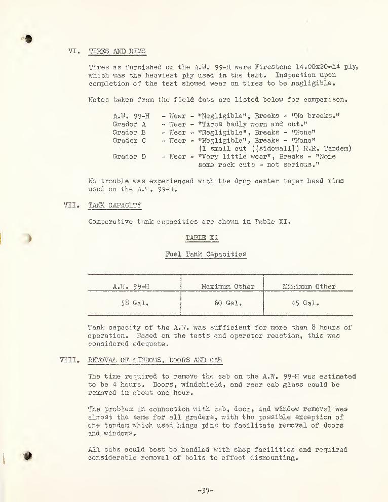
VI TIRES AND RIMS
*
Tires as furnished on the A.W. 99-H were Firestone 14*00x20-14 ply,
which was the heaviest ply used in the test* Inspection uponcompletion of the test showed wear on tires to be negligible.
Notes taken from the field data are listed below for comparison.
A.W. 99-H - WearGrader A - WearGrader B - WearGrader C - Wear
Grader D - Wear
"Negligible", Breaks - "No breaks.""Tires badly worn and cut."
"Negligible", Breaks - "None""Negligible" ,
Breaks - "None"
(1 small cut ((sidewall)) R.R. Tandem)"Very little wear" , Breaks - "Nonesome rock cuts - not serious."
No trouble was experienced with the drop center taper head rimsused on the A.W. 99-H.
VII. TANK CAPACITY
Comparative tank capacities are shown in Table XI.
TABLE XI
Fuel Tank Capacities
A.W. 99-H Maximum Other Minimum Other
58 Gal. 60 Gal. 45 Gal.
Tank capacity of the A.W. was sufficient for more than 8 hours ofoperation. Based on the tests and operator reaction, this wasconsidered adequate.
Vm. REMOVAL OF WINDOWS, DOORS AND CAB
The time required to remove the cab on the A.W. 99-H was estimatedto be 4 hours. Doors, windshield, and rear cab glass could beremoved in about one hour.
The problem in connection with cab, door, and window removal wasalmost the same for all graders, with the possible exception of
one tandem which used hinge pins to facilitate removal of doorsand windows.
All cabs could best be handled with shop facilities and requiredconsiderable removal of bolts to effect dismounting.
37 -

»
<

rx. LIGHTS
>
Intensity of lights, measured with a Weston meter three feetfrom the light source, varied from slightly under 800 to 1200for the five graders tested. The value for the A.W. 99-H was
900. From the limited testing of lights on all graders, it wasconcluded that all were adequate for travel illumination, but
possibly would not comply with State Highway codes in all
instances.
Lights on the A.W. 99-H were mounted on the lift ram supports,although optional provision was made for mounting near top of cab.
Data recorded for the lights as furnished with the A.W. 99-H are
tabulated below:
LocationNumberWeston IntensityProtectedAdjustableIlluminate bladeAdequate forhighway travel
- On lift ram supports- Two- 900- No- Yes- Not as mounted
- Yes
The observers agreed that in future consideration of lights formotor graders, more emphasis should be placed on adjustablemountings which will permit night illumination of the blade,protected lens on forward lights, and some provision for backuplighting.
X. ENGINE STARTING
The average time and temperature for four cold starts is shownin Table XII.
TABLE XII
Engine Starts
Maximum MinimumA.W. 99-H Other Other
Average Time 70 Sec. 133 Sec. 10 Sec.Average Temp. 46° 59° 42°
No difficulty was experienced in starting the A.W. 99-H engine at
any time during the test. The average starting time for thismachine was considered satisfactory.
-38 -

'I
.
I
<

XI. OPERATION OF CONTROLS
The discussion here is confined only to the actual controls as
contained in the cab.
Comparison of cab controls on the various graders tested indicatedcertain apparent good and bad features. Accessibility and ease of
control manipulation were given particular attention as to theiraffect on operator fatigue.
Controls on the A.W. 99-H were considered by observers to be
adequate and satisfactory, with exception of operation of the
blade circle lock. This latter control was reported as awkwardto operate and requiring considerable practice for satisfactoryoperation.
The A.W. 99-H grader had a steering lever instead of a wheel, whichallowed accessibility to hand controls normally restricted by a fullwheel.
XU. TURNING RADIUS
| (1) - Turning radius was established as the radius of the insidetrack of a complete turn. The distance betwreen inside and
outside tracks was taken as the required road width for the
turn. Table XIII gives turning radius and road width forthe A.W. as well os the maximum and minimum values for othergraders tested.
TABLE XIII
Turning Radius
A.W. 99-HMaximumOther
MinimumOther
Turn. Radius - Right 22 * ~§" 27 » -9«» 21 *
-
10 "
Turn. Radius - Left 22 *
-
9" 29* -3" 26 *
-
9"
Average Road Width 8 *-l» 13 v -5i" 12 *- 9§*
The A.W. 99-H turning radius was slightly in excess of theminimum for other machines, or 22 *-ijr" compared to 21 *-10".
This data, although accurately recorded, is misleading.The machine for which the minimum was recorded had anunbalanced turning radius right and left as follows:Right: 21* -10" , Left: 28 *-l". Efforts to correct thiscondition were unsuccessful. Equally divided, this wouldresult in a turning radius of 24*-ll-|-", or in excess of theA.W. 99-H. It could be concluded that the A.W. 99-H had theshortest turning radius of the group.
-39-

r
»
«
#
c
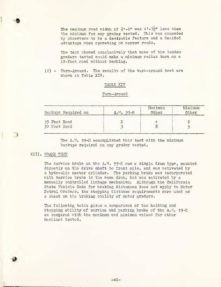
The maximum road width of 8 *-lM was 4 , - 7-
2 " less than
the minimum for any grader tested. This was concededby observers to be a desirable feature and a decided
advantage when operating on narrow roads.
The test showed conclusively that none of the tandemgraders tested could make a minimum radius turn on a
12 -foct road without backing.
(2) - Turn-Around. The results of the turn-around test are
shown in Table XIV.
TABLE XIV
Turn-Around
Maximumj
MinimumBackups Required on
|A.W. 99~H
j
Otherj
Other
35 Foot Road 2l
4 2
30 Foot Road 3 8 5
The A.W. 99-H accomplished this test with the minimumbackups required on any grader tested.
XIII. BRAIGS TEST
The service brake on the A.W. 99-K was a single drum type, mounteddirectly on the drive shaft to front axle, and was activated bya hydraulic master cylinder. The parking brake was incorporatedwith service brake in the same drum, but was activated by a
manually controlled linkage mechanism. Although the CaliforniaState Vehicle Code for braking distances does not apply to MotorPatrol Graders, the stopping distance requirements were used as
a check on the braking ability of motor graders.
The following table gives a comparison of the holding andstopping ability of service and parking broke of the A.W. 99-Has compared with the maximum and minimum values for othermachines tested.

r'
*
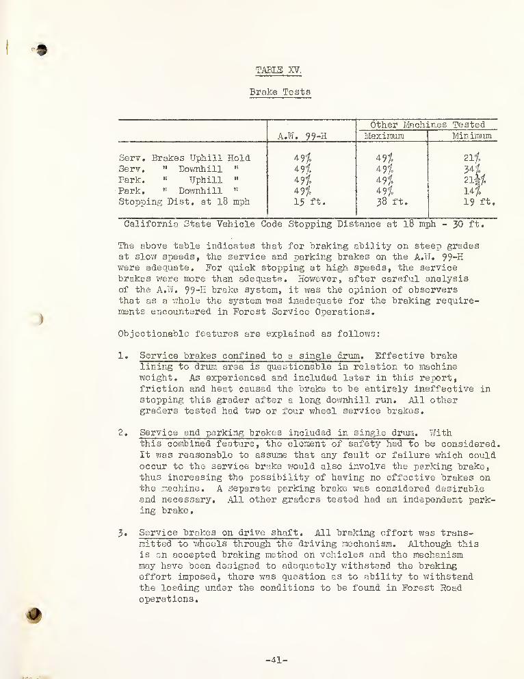
TABLE XV.
9
Brake Tests
A.W. 99-H
Other Machines TestedMaximum Minimum
Serv. Brakes Uphill Hold 49% 491 ZlfServ. " Downhill 491 4 9 7.
Park. »•> Uphill " 49t 49% 21§/.
Park. ” Downhill 497* 49fo 14/o
Stopping Dist. at 18 mph 13 ft. 38 ft. 19 ft.
California State Vehicle Code Stopping Distance at 18 mph - 30 ft.
The above table indicates that for braking ability on steep gradesat slow speeds, the service and parking brakes on the A.W. 99-Hwere adequate. For quick stopping at high speeds, the servicebrakes were more than adequate. However, after careful analysisof the A.W. 99-H brake system, it was the opinion of observersthat as a whole the system was inadequate for the braking require-ments encountered in Forest Service Operations.
Iy
Objectionable features are explained as follows:
1. Service brakes confined to a single drum . Effective brakelining to drum area is questionable in relation to machineweight. As experienced and included later in this report,friction and heat caused the brake to be entirely ineffective in
stopping this grader after a long dovrahill run. All othergraders tested had two or four wheel service brakes.
2 . Service and parking brakes included in single drum . Withthis combined feature, the element of safety had to be considered.It was reasonable to assume that any fault or failure which couldoccur to the service brake would also involve the parking brake,thus increasing the possibility of having no effective brakes onthe machine. A separate parking brake was considered desirableand necessary. All other graders tested had an independent park-ing brake
•
3 . Service brakes on drive shaft . All braking effort was trans-mitted to wheels through the driving mechanism. Although thisis an accepted braking method on vehicles and the mechanismmay have been designed to adequately withstand the brakingeffort imposed, there was question as to ability to withstandthe loading under the conditions to be found in Forest Roadoperations.
+
-41-
*
' .
<
\

; %
I )
l) #
Although it was evident from the tests that the stoppingand holding ability of the AfW* 99-H brakes was better thanthe normal requirements, it was the consensus of observers
that they were inadequate for the reasons cited.
XIV. WALKING TEST
1. The highway walking test was divided into two sections.
The first covered travel over asphalt paved highway withgrades up to two percent. The second section covered
travel over dirt highway with grades up to eight percent.
2. The truck trail walking test was divided into uphill anddownhill sections. Grades varied from 14 percent uphillto 10 percent downhill.
Table XVI gives comparative speed data in miles per hour for
each, section of the highway and truck trail runs as well as
overall mph for each distance.
table xvi.
Travel Speed (mph)
Route Distance A.W, 99-HOther Graders TestedMaximum Minimum
Paved highway 4.2 Mi. 13.80 24.60 18.30Dirt highway 1.9 5t 12.35 17.34 14.07Total highway 6.1 " 14.30 19.94 17.70Uphill truck trail 1.35 " 6.11 6.36 4.49Downhill truck trail 2.3 " 9.13 16.24 9.69Total truck trail 3.69 " 7.70 9.98 8.27
In both the highway and truck trail travel speed tests, the A.W. 99-Hwas recorded as the slowest of all machines tested. It was duringthe latter test that the service and parking brakes failed to holdthe grader to a desired speed, nor could the unit be braked to a
stop. As noted in Table XVI the downhill test consisted of 2.3 milesof narrow winding road with one short radius curve and numerous curvesof variable radius, the average grade was 9/0.
The Forest Service operator did not realize the steepness of thedown-grade and shifted to a higher gear than should hove been used.Consequently, the brake was used excessively, became too hot result-ing in a near miss to a serious accident. Stopping the grader wasdifficult during remainder of the test . Obviously the operator wasat fault in misusing the brakes, but the fact that it could happenwith any operator, emphasizes the need for a separate emergency brake.
- 42 -

)

XV. BREAKPOINTS
The A.W. 99-H did not fail during the tests because of breakdowns.
XVI. FINAL CHECK
On completion of the field tests, all machines were returned to
the "flatland 1’ area. All complaints recorded were given a final
check. In addition, a thorough check of each grader was made byshop mechanics.
Only one minor item was detected in the final check of the A.W. 99-H.A small crack was found in a part of the circle lock device. Sincethe part was under no evident stress and the crack was in a weld, it
was concluded to be a weld shrinkage break.
I
-43-

i

DISCUSSION OF RESULTS
Field Tests
I. SLIDE REMOVAL
One fact which became apparent during field tests was the lack of
knowledge of various operators as to how much work a machine wascapable of doing. In the slide removal test, several of the
operators questioned the ability of any grader to perform the
task assigned. As the tests progressed, the performance of
machines improved as the operators gained more experience.Table XVII gives comparative times required for machines to climb
over the test slide.
TABLE XVII
Slide Removal
Other Machines TestedA.W. 99-H Maximum Minimum
Time to ClimbSlide 50 Min. 0 Sec. 41 Min. 0 Sec. 19 Min, 57 Sec.
The time required to climb the slide was reflected in a combinationof operator and grader ability, plus the method used. For example,the time for one machine on a rerun was one fourth the original time.The reduced time factor was attributed to two causes: First, theoperator gained experience by his original operation of a grader ona test with which he wasn't familiar. Second, in the interim, hehad the opportunity to observe time saving techniques demonstratedby other operators performing the same test, thus enabling him tobeneficially apply the experience and knowledge gained.
The true value of the slide test was not in determining the time re-quired, method of attack, number of passes, etc., but in the appraisalof grader maneuverability, traction, blade stability, and operatorfatigue.
Although the time for the A.W. 99-H was the highest recorded, dueconsideration was given to the fact that this machine was the firstto attempt the slide test. Some graders reran the slide test tobetter their time; however, the A.W, 99-H performed satisfactorilyand no rerun was thought necessary.
»
-44-

••
'
.
.
.!

9
In this test, however, it was noted that complete loss of tractionof either front wheel automatically voided all drive power to both
front wheels, thus restricting power and tractive effort to the two
rear wheels.
Although some lihequal front wheel slippage was noted in otherphases of the overall test, at no time was the A.W. 99-H
considered lacking in tractivo ability. Figure 1J> shows slide
used for this test#
Fig. 13. Test Slide A.W. 99-H
II. IN-OJHVE
In figure 5 is depicted q typical condition often encountered inForest road maintenance# Here the grader which was capable ofturning a short radius curve, using the minimum road width, wouldhave the advantage* Results of the test showed that the A.W. 99-Hwas far superior to the tandem graders.
,The average track width
required for tandem graders was 19*-9W , as against 9 ? -7^’ for theA.W, 99-H. Data obtained from this test substantiated the conclu-sions of the ”flatlandsw turning radius runs.
«
45

1
'C
I

III. GRADING OF DIPS
No difficulty was encountered with the A.W. 99-H in the grading of
dips. Maneuverability of machine was adequate in all respects.
It was anticipated by observers that the blade locking devicemight handicap operations in this phase of the test, but it wasnoted that the blade could be angled as desired by rear-wheelsteering.
IV* DITCHING
This test was conducted in the same area and adjacent to test
strips on which other units operated. This insured comparableoperating conditions. The A.W. 99-H ranked second best in elapsedtime. The table of ditching time, Table XVIII, shows the comparisonbetween the A.W. 99-H and other machines in the test.
TABLE XVIII
Ditching
Other Machines TestedA.W. 99-H Maximum Minimum
Time to Construct
' r '
Ditch 8 Hr. 58 Min, 11 Hr. 33 Min. 8 Hr. 20 Min.
It was recognized that this ditching test was most severe and beyondthe normal operations encountered or anticipated. It was, in effect,an accelerated aging test to determine the ability of the graders.
In this difficult test the A.W. 99-H showed superiority in operatingunder heavy going without abuse to machinery. Maneuverability ofthe machine due to rear steering showed to advantage in removing thelarge embedded rocks. The power sideshift of the blade provided addi-tional advantage for the A.W. 99-H' in this work by side shifting theboulders from the work area. Since material was sidecast uphill, thetandem graders had difficulty in maintaining an ’’even keel” whereasthe A.W. 99-H could steer both sets of wheels directly into the loadthereby maintaining tractive effort in the line of thrust withminimum skidding down slope.
V. SCARIFYING
The work of scarifying the ditch surface was accomplished equallywell by all graders. The A.W. 99-H completed this test withoutincident
.
46-

€
'• '-M
.
•
,.
•
(
' V
' : ‘
..
c
§)
VI. BAM SLOPING
The A.W. 99^H aecomplished the bank sloping test with ease andexoelled in maneuverability, and control of both machine andblade* Since the rear wheel3 could be steered adjacent to thebank at ell times, the job of banksloping of incurves was easilyaccomplished. Figure 14 and 15 shows bank sloping before andafter operation.
Fig. 14. Area before Banksloping
<p47-
I
t %'

TO. DRIFTING
TABLE XXX
Drifting
9
Other Machines TestedA,W. 99-H Maximum Minimum
Cu* yds./ Min. Moved 1.1 1.29 .97
Th© A.W. 99-H rated third best in this test. Although no particulardifficulty was experienced, test observers critically compered theinability (referred to as an inability because not recommended byfactory) of this unit to swing blade under load.
Other graders were noted to angle blade into bank material, fillblade, and without stopping machine, swing blade to straight acrossposition and proceed to point of material dispersal.
In operation of the A.W. 99-H the blade was filled while angled,the grader was then stopped to unlock circle, blade was swung tostraight across position and circle relocked. Material was thencarried in the same manner as others. This procedure was compara-tively more time consuming.
48—

<

%VIII. HORIZONTAL MOVEMENT OF WINDROW
In this test, results were reduced to cu. yds. ft. sidecast per
minute. This factor is necessary for comparative purposes, since
each machine moved a different quantity of dirt variable distancesto the side, and in variable periods of time. Table XX gives the
results.
TABLE XX
Windrow Cu. Yds .-Ft. Alin.
A.W. 99-HGrader
a;
: b1
c D
85.5 107*01
149.0|
145.2
L_
96.5
In production, the A.W. 99-H rated fifth* No difficulty was en-countered during this test and the finished result was satisfactory.In analyzing the low production of the A.W. 99-H as compared to theother graders tested, it was decided by observers that this was theone test where the 76 horsepower engine was inadequate to operatewith an out put comparable to that of more powerful graders.
DC. SHAPING OF BERMS
The work in this test was relatively light and all units were ratedequally. No significant features or failures were evident.
X. HILL CLIM3
In this test all machines climbed the 49$ grade in forward gear.In reverse, the tandem machines were able to back up to the sectionof the hill on which the slope varied from 39$ to 41$. At thispoint failure was due to lack of traction. The four-wheel-driveA.W. 99-H was the only grader to climb the hill in reverse,
XI. UPHILL GRADING
Grades on sections selected for this test averaged about 15$ androad bed material was chiefly decomposed granite. Table XXI givesthe comparative overall time for the graders to complete gradingon the 500 ft, test section of road.
XJ
#
49-

f
........
' i
. f' <
(
.
*'
‘
.
f
(

TABLE XXI
Uphill Grading
Other Machines TestedA.W. 99-H Maximum Minimum
Time to do
r n r T w r1 1 r
Uphill Grading (500*) 5 Min. 35 Sec. 4 Min. 6 Sec. ' 2 Min. 50 Sec.
The A.W. 99-H completed this test satisfactorily in average time.
XII. ROAD GRADING
The three-pass 500 foot road maintenance test was preliminary to thetwo mile maintenance run. The satisfactory performance in this testassured observers of the ability of machine and operator to proceedwith the longer test to follow.
XIII. ROAD MAINTENANCE
The two mile road maintenance test was the last of the field testsperformed, and combined all of the operations normally required inroad grading, with the exception of bank sloping. This being thecomposite of the previous tests, observers were able to recheckvarious phases of operation previously noted, as well as to appraisethe ability of the machine in shifting from one operation to anotherwith minimum loss of productive time.
The course selected for the A.W. 99-H test was 2 miles long, had 45interceptor dips, and had grades up to 20 percent. The roadbed waschiefly decomposed granite. Three passes were made averaging 1.47miles per hour, or a total time of 4 hours and 4 minutes for the test.Speed of other graders ranged from 1.52 to 1.9 miles per hour. Aconsiderable portion of the variation in time for each grader couldbe directly attributed to operator differences in interpretationof the problem.
The Forest Service engineer, in his appraisal of this phase of thetest, reported that performance of the A.W. 99"H was above theaverage in comparison to results obtained from other graders. Theoperator disregarded the time factor in favor of attaining qualityresults.
Appearance of the finished job was carefully observed in an attemptto detect instability of the machine due to absence of the tandemwheel feature. The smooth surface produced by the blade indicatedthat Fine grading could be accomplished by the A.W.
>50 -


%The advantage of four-wheel steering; was very evident in this testsince bGcking-up was unneccessary on sharp turns.
One feature of the A.W# which showed to advantage in the roadmaintenance test was its ability to place the berm on the extremeedge of the road bed on sharp outcurves where turn-outs wereoriginally constructed. Side shift of the blade by the power ram,and rear wheel steering, made this type of work possible resultingin a more thorough maintenance job.
Many photographs were taken during the test. A few which showbefore and after conditions are included in Figures 16 to 19
.
>'
-51-

; . -; "
, ,
,
"

.

Fig. 18. Road Maintenance - Dip Construction Before Test
-53


BULLDOZING LEST - FLATLAND AND FIELD
Due to the specialized nature of bulldozer attachments on graders,this portion of the test was treated independently of the basic gradertest. Considerable interest in the possibilities of such an attach-ment was indicated by observers, and as a result, the Austin-WesternCompany and one other grader company voluntarily sent for and installedtheir respective dozer attachment for testing.
Fig. 20. A.W. Bulldozer
Comparative data for both dozer units taken in the Flatland Testwas as follows:
Weight, blade assemblyA.W. 99-H1500 lbs.
Other UnitMo' Tbs .
''
" attach. ” — 1480 lbs." total " lpOO lbs. 2360 lbs.
Blade length Q ? Q'» 10»-1"" height 2 * -7”
Pitch Fixed *0CO101
—
1
No. cutting edges 1 2
Cutting edge size 8"Wx9 ?L 6"Wx5«LMax . angle R 0° (Fixed ) 33°
" " L 0° 33°Type control Hyd. Mech.Max. lift above ground 17” 17"Max. lower below ground 6" 6"
Side shift range 0" 8" R and L


%FIELD TEST OF_SLIDE REMOVAL WITH DOZER ATTACHED
This particular operation was considered as tho roost logioalapplication for a dozer on a motor grader. It appearedreasonable that the machine would simulate a tractor with dozer inremoving a slide by head-on approach. Figure 21 shows a picture ofthe slide area after removal by using bulldozer blade.
Fig. 21. Test Area after Dozer Operation
The first test of the machine was to remove sufficient slidematerial to allow the grader to pass over the obstruction. Thiswas accomplished in 18 minutes as compared to 19 min... 10 sec. forthe other unit*
A second test required that the slide be completely removed and thematerial spread on the road bed beyond. In this test, the A.W* 99-Hrequired 2 hours 53 minutes as compared to 1 hour and 56 minutes forthe other unit.
m
-55-

I
CONCLUSIONS
Conclusions formulated and expressed are the result of
experience with and test of the machine submitted for trial.
FLATLAND TESTS
1. Weight distribution for the A.W. grader differed from anyother grader tested due to four wheel drive.
2. Drive wheel weight horsepower ratio was highest of all graderstested because of four wheel drive.
3. Overall dimensions were less than those of any other grader tested.
4. Speed variations, as allowed by rear axle and transmissionratios, were adequate.
3 . Engine performance is satisfactory.
6. Method and principle of starting is considered satisfactory.
7. Maneuverability of blade (with exception of circle lock) in
all tested operating positions is entirely acceptable. It
is the opinion of test observers that the A.W. 99-H has themost desirable features of blade maneuverability of all graderstested.
8. The side shift of the blade on the A.W. 99-H was consideredthe most desirable of the methods used on other graders tested.
9 . Visibility from the cab was adequate for normal field operation.
10. Four wheel steer adequately handled operations requiring lean-ing front wheels on other type of graders,
11. Front axle ground clearance was less than that of any othergrader tested. No difficulty because of lack of clearance wasnoted during the tests.
12. Daily maintenance requirements were considered reasonable.
13. Tires as furnished were the heaviest used during test. Wearwas negligible.
14. Rims, as furnished, were satisfactory.
13. Fuel tank capacity was adequate for a full day’s operation.


16. The time and effort required for cab removal and reinstallationwas comparable to that of other graders.
17. Lights were satisfactory for forward travel, but only fair forblade illumination.
18. Controls were adequate and satisfactory with exception of
circle locking device which is considered awkward to operate.
19. Comparatively, the action of hydraulic control levers wassmoother and much less fatiguing than the mechanical type ofcontrols as used on other graders.
20. Turning radius was the shortest of any other graders tested.
21. Service end foot brakes were not approved since they failed toperform satisfactorily on the truck trail road test.
22. Operational travel speeds were adequate for road maintenance.Highway speed was slowest of all units tested.
FIELD TESTS
1. While time required to accomplish the slide removal test wasin excess of other graders, the A.W. was judged capable ofperforming this work satisfactorily.
2. The incurve test shoived that the A.W. was the only graderwhich could operate on short radius curves where road widthwas less than 12 feet without backing.
3 . Grading of dips was accomplished with ease,
4. In the ditching operation, the A.W. showed ability to operateunder heavy loads without abuse to the machine and completedthe job with comparative ease.
5« The A.W. had no difficulty in test scarifying operations.
6. In the bank sloping test the A.W. excelled. Four wheel steerand hydraulic control of the blade were the main contributingfactors.
7. In the drifting test, the A.W. rated below average due to thenecessity of stopping to release the circle lock.
0. The A.W. in the windrow test moved less material than averagefor other graders.
-57-

c
(#

9.
The A.W. was equal to all graders tested in climbing steepslopes in a forward direction and superior when in reverse.
10. The uphill grading test indicated that the A.W. could performuphill to the required standard.
11. In the two mile maintenance test, the A.W. required more timethan any other grader, but the quality of work was appraisedas above overage.
-58-

••
•
•
.
.
...
.
*

APPENDIX

i
*
/

HATING TABLE
As a check on the results of the motor grader test, arating table was prepared to include several of the more common itemsgenerally considered when discussing patrol graders. The theory inthe preparation of this table, if it can be so called, is based some-what on the laws of random sampling.
Eight men - three engineers, one ranger, one mechanical drafts-man-designer, two Depot Superintendents, and one Regional Office staffman - completed a rating table for the five graders, to include twenty-three items normally associated with equipment of this type. The itemsv/ere listed only as headings with no detail to cover definition. In-
structions for preparation requested that the rater draw his own conclus-ions as to the inference in the item, and rate accordingly. Rating wasto be made by indicating the best as one, second best - two, etc,, withmachines of equal ability being rated by the same digit.
It was also recognized that all 23 of the rating items did notbear the same weights as to importance. Accordingly, each person pre-paring the questionnaire was requested to evaluate the relative import-ance of each and establish some weighting scale to cover.
A typical final form is shown with the items weighted, but with-out the ratings for the individual graders.

<
I
'

GRADER SCORING SHEET
WeightRating A°»C Cat. Rome A-»W Adams
Blade Opr. 6
Engine Starting 3,
Transmission Shift 5
Opr. of Controls 6
Breakdowns 4.
Availability of Parts 4
Maint. Wee. to Opr. 1
Walking Speeds 3,
Maneuverability of Machine 5.
Safety - Brakes 7_
Visibility 5_
Controls Shift 6.
Opr. Fatigue 5_
Opr. Training Necessary 1
Dip Const. & Maint. 8
Ditching 5
Drifting 3
Bank Sloping 2.
Scarifying 5,
Move Windrow 6_
Remove Slides 6^
Read Maint. 8_
Fine Grading 2.
-ii-
(

The eight forms were converted to final rating in percent and
aro tabulated below:
RATING TABLE
IndividualGraderA
. GraderB
Grader0
GraderD A.W. 99-H
1 28.8 68.0 59.0 50.8 62.8
2 30.0 64.7 62.4 48.0 51.0
3 28.2 63.4 41.7 39.2 73.54 68.1 91.0 89.6 75.3 91.9
5 23.2 58.5 52.8 38.8 80.26 31.7 67.1 66.4 44.0 67.97 43.7 73.0 65.8 58.0 77.88 20.5 36.1
-
66.1 26.8 47.4
Average 34.3 63.3 63.0 47.6 69.1
It is significant that in all the ratings, Graders A and Dheld the positions of fourth and fifith respectively withouttransposition and by a substantial margin. Graders B and the
A.W. 99-H changed from their averaged relative position threetimes, while Grader C changed only twice.
It is evident from the ratings that the concensus of theobservers in mentioning the advantageous merits of each graderseveral times in the body of the report, can be substantiated,and is defined as follows:
A.W. 99-H - Most often - FirstGrader B - »» n - SecondGrader C - « it - ThirdGrader D - Definitely - FourthGrader A _ it 19 - Fifth
If further deduction from the table were permitted, andif the sample of eight men could be taken as a cross-section ofthe entire field, it could be concluded that the A.W. 99-K is themost desirable for overall Forest Service work, xvith Grader Band C as acceptable alternates. Graders D and A would, becauseof their relative low rating, be classed as undesirable.
Finally, it could be said that even though the A.W. 99-His rated the highest, according to the table and comparison withthe ultimate in graders for Forest Service work, it is only69 .lfo effective.

i(
i
i

AM DETONATOR BRAKE TESTER
The electrically operated detonator brake tester, shown inphotograph. Pig. A, is used to measure the effectiveness of equip-ment brakes. Mounted on the machine being tested, it is operatedby two switches «• the first controlled by an observer and the secondmounted on the brake pedal*
Fig, A. AM Detonator Brake Tester
With the machine moving at the predetermined test speedy theobserver operates the switch that releases solenoid 1 and allowsits spring loaded hammer G to fire a blank cartridge in the block B.
The force of the explosion expels chalk in the block and makes amark on the pavement* On hearing the shot, the operator hits thebrakes
9causing the brake switch to release Solenoid 2, which fires
a second piece of chalk to the pavement* When the machine comes to acomplete stop a third chalk mark is made on the pavement directlyunder the detonator firing blocks.
The distance between the first and second shalk marks is
measured and, since the speed of travel is known, can be convertedinto operator reaction time. The measurement between the second and
third marks is the distance required to bring the vehicle to a stopat the given speed-,
A complete description of the operation and use of this braketester is available at the Arcadia Equipment Development Center,
701 N. Santa Anita Ave., Arcadia, California*

• . .' J
K
„ <- W. Ju'i .Jt. •* ,*•“*.. j .. *• ’ *
i. C v-ir -to o-W 'U.t''' :>*’
V v . * Vri .r. <*•.; U-*i v\VW ^fUie M ' '«
:'v
. ::&**% *»£' • '«*§ r
. , f ,
A /...'•
,
:v.r
.
»j£T. I
4 '
. ,i> v,j4: •«*.! *
:
!
«si
.: .
. /: f
lr . a -.tfr'i
r
!
.; ?x
.
**•*
•
' p&tiSvW* /* '
•<*
’•* to* ^
; ;f;
: - r
; > V*.;
J
;;
..^v;- 4 .'h • *!,'
7 .
•'•'*/•
noV*- • n't 1•*’
•’'A•
•.. x». fs'v,.K;vyrHfj •t-*; • *.;/
* "
:i
•
.
•• • ' :vi' U-'f
'
. ;V-' ,<
'
$!*'• * f-**
.**.>. ‘'J-- -.;t- S'. ••'•’ •'•
-?t r;t<3ff.i7 ’f
f:r. wt- •
- .......
4-it
: ,v.'*
;.%jjo Lr , .
.
'
. .,’V'
'' T-?'’ :
•
•' ' ‘ Jl
.
j- r.,r<
-.
• • vV^v. r* V
•
•
i;
’U ,»’! i,
-r ... ,v ‘ i yJx*. «• *; :4
*;•>;•,
**j•
. \,rr
j ,
1
i or.,
'.> >•>
'<*. /'.u
£..,.
' 'SU.rJc .i.r •:
i . J ri
'
I)' *4 r
' j vi- •
*''
ft- .-A-
.)•
,. i:
;
•;
r'p. .-.V
;s •>' fc
V .' r.V" is J /?5 .
'’r&vV 'H -•Mr.tfti*- . '-vs;
; .

>;v