Morgan Quigley, Alan Asbeck, and Andrew Y....
8
A Low-cost Compliant 7-DOF Robotic Manipulator Morgan Quigley, Alan Asbeck, and Andrew Y. Ng Abstract—We present the design of a new low-cost series- elastic robotic arm. The arm is unique in that it achieves reasonable performance for the envisioned tasks (backlash-free, sub-3mm repeatability, moves at 1.5m/s, 2kg payload) but with a significantly lower parts cost than comparable manipulators. The paper explores the design decisions and tradeoffs made in achieving this combination of price and performance. A new, human-safe design is also described: the arm uses stepper motors with a series-elastic transmission for the proximal four degrees of freedom (DOF), and non-series-elastic robotics servos for the distal three DOF. Tradeoffs of the design are discussed, especially in the areas of human safety and control bandwidth. The arm is used to demonstrate pancake cooking (pouring batter, flipping pancakes), using the intrinsic compliance of the arm to aid in interaction with objects. I. INTRODUCTION Many robotic manipulators are very expensive, due to high-precision actuators and custom machining of compo- nents. We propose that robotic manipulation research can advance more rapidly if robotic arms of reasonable perfor- mance were greatly reduced in price. Increased affordability can lead to wider adoption, which in turn can lead to faster progress—a trend seen in numerous other fields [1]. However, drastic cost reduction will require design tradeoffs and compromises. There are numerous dimensions over which robotic arms can be evaluated, such as backlash, payload, speed, band- width, repeatability, compliance, human safety, and cost, to name a few. In robotics research, some of these dimensions are more important than others: for grasping and object ma- nipulation, high repeatability and low backlash are important. Payload must be sufficient to lift the objects under study. Human-safety is critical if the manipulator is to be used in close proximity to people or in classroom settings. Some areas of robotics research require high-bandwidth, high-speed manipulators. However, in many research set- tings, speed and bandwidth may be less important. For example, in object manipulation, service robotics, or other tasks making use of complex vision processing and motion planning, large amounts of time are typically required for computation. This results in the actual robot motion requiring a small percentage of the total task time. Additionally, in many laboratory settings, manipulator motions are often deliberately slowed to give the programmers time to respond to accidental collisions or unintended motions. In this paper, we present a robotic arm with similar performance on many measures to high-end research robotic Morgan Quigley, Alan Asbeck, and Andrew Y. Ng are with the Depart- ment of Computer Science, Stanford University, Stanford, CA 94305, USA mquigley, aasbeck, [email protected] Fig. 1. The low-cost compliant manipulator described in this paper. A spatula was used as the end effector in the demonstration application described in this paper. For ease of prototyping, lasercut plywood was used as the primary structural material. arms but at a drastically lower single-unit parts cost of $4135. A shipped product must include overhead, additional design expenditures, testing costs, packaging, and possibly technical support, making a direct comparison with the parts cost of a research prototype rather difficult. However, we document the parts cost of our manipulator in order to give a rough idea of the possible cost reduction as compared to current commercially-available manipulators. Our experiments demonstrate that millimeter-scale re- peatability can be achieved with low-cost fabrication tech- nologies, without requiring the 3-d machining processes typically used to construct robotic manipulators. A set of requirements were chosen to ensure the arm would be useful for manipulation research: • Human-scale workspace • 7 Degrees of freedom (DOF) • Payload of at least 2 kg (4.4 lb.) • Human-safe: – Compliant or easily backdrivable – Flying mass under 4 kg • Repeatability under 3 mm • Maximum speed of at least 1.0 m/s • Zero backlash To meet these requirements at the lowest possible cost, a new arm design was developed. The arm uses low-cost stepper motors in conjunction with timing belt and cable drives to achieve backlash-free performance, trading off the cost of expensive, compact gearheads with an increased arm volume. To achieve human safety, a series-elastic design was
Transcript of Morgan Quigley, Alan Asbeck, and Andrew Y....

A Low-cost Compliant 7-DOF Robotic Manipulator
Morgan Quigley, Alan Asbeck, and Andrew Y. Ng
Abstract— We present the design of a new low-cost series-elastic robotic arm. The arm is unique in that it achievesreasonable performance for the envisioned tasks (backlash-free,sub-3mm repeatability, moves at 1.5m/s, 2kg payload) but witha significantly lower parts cost than comparable manipulators.The paper explores the design decisions and tradeoffs madein achieving this combination of price and performance. Anew, human-safe design is also described: the arm uses steppermotors with a series-elastic transmission for the proximal fourdegrees of freedom (DOF), and non-series-elastic robotics servosfor the distal three DOF. Tradeoffs of the design are discussed,especially in the areas of human safety and control bandwidth.The arm is used to demonstrate pancake cooking (pouringbatter, flipping pancakes), using the intrinsic compliance of thearm to aid in interaction with objects.
I. INTRODUCTION
Many robotic manipulators are very expensive, due tohigh-precision actuators and custom machining of compo-nents. We propose that robotic manipulation research canadvance more rapidly if robotic arms of reasonable perfor-mance were greatly reduced in price. Increased affordabilitycan lead to wider adoption, which in turn can lead tofaster progress—a trend seen in numerous other fields [1].However, drastic cost reduction will require design tradeoffsand compromises.
There are numerous dimensions over which robotic armscan be evaluated, such as backlash, payload, speed, band-width, repeatability, compliance, human safety, and cost, toname a few. In robotics research, some of these dimensionsare more important than others: for grasping and object ma-nipulation, high repeatability and low backlash are important.Payload must be sufficient to lift the objects under study.Human-safety is critical if the manipulator is to be used inclose proximity to people or in classroom settings.
Some areas of robotics research require high-bandwidth,high-speed manipulators. However, in many research set-tings, speed and bandwidth may be less important. Forexample, in object manipulation, service robotics, or othertasks making use of complex vision processing and motionplanning, large amounts of time are typically required forcomputation. This results in the actual robot motion requiringa small percentage of the total task time. Additionally, inmany laboratory settings, manipulator motions are oftendeliberately slowed to give the programmers time to respondto accidental collisions or unintended motions.
In this paper, we present a robotic arm with similarperformance on many measures to high-end research robotic
Morgan Quigley, Alan Asbeck, and Andrew Y. Ng are with the Depart-ment of Computer Science, Stanford University, Stanford, CA 94305, USAmquigley, aasbeck, [email protected]
Fig. 1. The low-cost compliant manipulator described in this paper.A spatula was used as the end effector in the demonstration applicationdescribed in this paper. For ease of prototyping, lasercut plywood was usedas the primary structural material.
arms but at a drastically lower single-unit parts cost of $4135.A shipped product must include overhead, additional
design expenditures, testing costs, packaging, and possiblytechnical support, making a direct comparison with the partscost of a research prototype rather difficult. However, wedocument the parts cost of our manipulator in order to givea rough idea of the possible cost reduction as compared tocurrent commercially-available manipulators.
Our experiments demonstrate that millimeter-scale re-peatability can be achieved with low-cost fabrication tech-nologies, without requiring the 3-d machining processestypically used to construct robotic manipulators.
A set of requirements were chosen to ensure the arm wouldbe useful for manipulation research:
• Human-scale workspace• 7 Degrees of freedom (DOF)• Payload of at least 2 kg (4.4 lb.)• Human-safe:
– Compliant or easily backdrivable– Flying mass under 4 kg
• Repeatability under 3 mm• Maximum speed of at least 1.0 m/s• Zero backlashTo meet these requirements at the lowest possible cost,
a new arm design was developed. The arm uses low-coststepper motors in conjunction with timing belt and cabledrives to achieve backlash-free performance, trading off thecost of expensive, compact gearheads with an increased armvolume. To achieve human safety, a series-elastic design was

used, in combination with minimizing the flying mass of thearm by keeping the motors close to ground. The resultingprototype is shown in figure 1.
A brief outline of this paper is as follows. Section II givesan overview of other robotic arms used in robotics research.Section III gives an overview of the design of the arm, anddiscusses tradeoffs with its unique actuation scheme. SectionIV discusses the series compliance scheme, and sections V,VI, and VII discuss the sensing, performance, and control,respectively. Section VIII discusses application of the roboticarm to a pancake-making task, followed by a conclusion.
II. RELATED WORK
A. Robotics research arms
There are a number of robotic arms used in robotics re-search today, many with unique features and design criteria.In this section, we discuss some recent widely-used and/orinfluential robotic arms.
The Barrett WAM [2], [3] is a cable-driven robot knownfor its high backdrivability and smooth, fast operation. It hashigh speed (3 m/s) operation and 2 mm repeatability.
The Meka A2 arm [4] is series-elastic, intended for humaninteraction; other, custom-made robots with series-elasticarms include Cog, Domo, Obrero, Twendy-One, and theAgile Arm [5], [6], [7], [8], [9]. The Meka arm and Twendy-One use harmonic drive gearheads, while Cog uses plane-tary gearboxes and Domo, Obrero, and the Agile Arm useballscrews; the robots all use different mechanisms for theirseries elasticity. These arms have lower control bandwidth(less than 5 Hz) due to series compliance, yet that hasnot appeared to restrict their use in manipulation research.Several human-safe arms have been developed at Stanfordusing a macro-mini actuation approach, combining a series-elastic actuator with a small motor to increase bandwidth[10], [11].
The PR2 robot [12], [13] has a unique system that uses apassive gravity compensation mechanism, so the arms floatin any configuration. Because the large mass of the arm isalready supported, relatively small motors are used to movethe arms and support payloads. These small motors providehuman safety, as they can be backdriven easily due to theirlow gear ratios.
The DLR-LWR III arm [14], Schunk Lightweight Arm[15], and Robonaut [16] all use motors directly mountedto each joint, with harmonic drive gearheads to providefast motion with zero backlash. These arms have somewhathigher payloads than the other arms discussed in this section,ranging from 3-14 kg. They are not designed for humansafety, having relatively large flying masses (close to 14kg for the DLR-LWR), although demonstrations with theDLR-LWR III have been performed that incorporate a distalforce/torque sensor that uses the arm’s high bandwidth toquickly stop when collisions are detected.
Of the robotic arms discussed previously, those that arecommercially available are all relatively expensive, with end-user purchase prices well above $100,000 USD. However,there are a few examples of low-cost robotic manipulators
used in research. The arms on the Dynamaid robot [17]are constructed from Robotis Dynamixel robotics servos,which are light and compact. The robot has a human-scaleworkspace, but a lower payload (1 kg) than the class of armsdiscussed previously. Its total cost is at least $3500 USD,which is the price of just the Dynamixel servos. In videosof it in operation, it appears to be slightly underdamped.
The KUKA youBot arm is a new 5-DOF arm for roboticsresearch [18]. It has a comparatively small work envelope ofjust over 0.5 m3, repeatability of 0.1 mm, and payload of0.5 kg. It has custom, compact motors and gearheads, and issold for 14,000 Euro at time of writing.
B. Robot arms using stepper motors
Many robot arms have been made using stepper motors.Pierrot and Dombre [19], [20] discuss how stepper mo-tors contribute to the human-safety of the Hippocrate andDermarob medical robots, because the steppers will remainstationary in the event of electronics failure, as compared toconventional motors which may continue rotating. Further-more, they are operated relatively close to their maximumtorque, as compared to conventional motors which mayhave a much higher stall torque than the torque used forcontinuous operation.
ST Robotics offers a number of stepper-driven roboticarms, which have sub-mm repeatability [21]. However, theseare not designed for human safety. These are also rela-tively low-cost, for example the R17 arm (5-DOF, 0.75mworkspace, 2 kg payload) is listed for $10,950 USD. Severalother small, non-compliant robots were made in the 1980s-1990s used for teaching were also driven by stepper motors[22]. For example, the Armdroid robotic arm is 5-DOF andhas 0.6m reach; it uses steppers with timing belts for gearreduction, then cables to connect to the rest of the arm [23].
III. OVERALL DESIGN
The arm has an approximately spherical shoulder and anapproximately spherical wrist, connected by an elbow. Thejoint limits and topology were designed to enable the robot toperform manipulation tasks while being mounted near table-height, as opposed to anthropomorphic arms, which musthang down from the shoulder and require the base of thearm to be mounted some distance above the workspace.The shoulder-lift joint has nearly 180 degrees of motion,allowing the arm to reach objects on the floor and alsowork comfortably on tabletops. A summary of the measuredproperties and performance of the arm is shown in table I.
TABLE IMEASURED PROPERTIES OF THE ARM
Length 1.0m to wristTotal Mass 11.4 kg
Moving Mass 2.0 kgPayload 2.0 kg
Max. speed 1.5 m/sRepeatability 3 mm

Fig. 2. Actuation scheme for each of the proximal four DOF.
A. Actuation scheme
Figure 2 shows the actuation scheme for the proximal fourDOF. These joints are driven by stepper motors, with speedreduction accomplished by timing belts and cable circuits,followed by a series-elastic coupling. Using only timing beltsand cable circuits in the drivetrain results in low friction,minimal stiction, and zero backlash. This enables the armto make small incremental motions (less than 0.5mm), andthere is no gearing to damage under applied external forces.Combined with stepper motors, which have high torqueat low speeds, this leads to a low-cost but relatively highperformance actuation scheme. A downside to this schemeis that the reduction mechanisms occupy a relatively largevolume, making the proximal portion of the arm somewhatlarge.
Using a two-stage reduction of timing belt followed bycable circuit accomplishes not only a larger gear reductionthan a single stage, but also enables the motors to be locatedcloser to ground. The motors for the two most proximal DOFare grounded, and the motors for the elbow and upperarm rolljoints are located one DOF away from ground. By placing therelatively heavy stepper motors close to ground, the flyingmass of the arm is greatly reduced: below the second (lift)joint, the arm is 2.0 kg. For comparison, a typical adulthuman arm is about 3.4 kg [24].
The two-stage reduction scheme leads to coupling betweenthe motions of joints 1 and 2, and joints 2, 3, and 4. However,this coupling is exactly linear and can easily be estimated as afeedforward term in software. The routes of the timing beltsand cables can be seen in figure 3. After the timing beltsand cable circuits, the proximal four DOF have series elasticcouplings between the cable capstan and the output link,discussed in section IV. These are used to provide intrinsiccompliance to the arm, as well as providing force sensing(section V).
The distal three DOF are driven by Dynamixel roboticsRX-64 servos. These joints do not have compliance asidefrom limiting the torques. However, the compliance of theproximal four DOF allows the end effector to be displacedin Cartesian space in three dimensions, barring kinematicsingularities where only two dimensions will be compliant.
B. Tradeoffs of using stepper motors
Using stepper motors as actuators has a number of ad-vantages. Stepper motors excel at providing large torquesat low speeds, which is the target regime of the arm. Theyrequire a relatively low gear reduction, which can be accom-plished with timing belts and cable drives. In the prototype
Fig. 3. Cable routes (solid) and belt routes (dashed) for the shoulder lift,shoulder roll, and elbow joints. All belt routes rotate about the shoulder liftjoint. The elbow cables twist about the shoulder roll axis inside a hollowshaft. Best viewed in color.
Fig. 4. Compact servos are used to actuate the distal three joints.
manipulator discussed in this paper, the effective reductionswere 6, 10, 13, and 13, respectively, for the first four joints.DC motors, for comparison, generally require a significantlylarger gear reduction through a gearbox that would be eithersusceptible to backlash or moderately expensive.
The stepper motors also act as electromagnetic clutches,improving safety if large forces are accidentally applied atthe output. If a force is applied that causes a stepper toexceed its holding torque, the stepper motor will slip and thearm will move some distance until the force is low enoughthat the stepper can re-engage. The stepper holding torque isapproximately 60% more than the maximum moving torque(and hence the maximum payload of the arm), large enoughto avoid needlessly slipping but small enough to make thearm human-safe.
However, there are a few downsides of the steppers actingas an electromagnetic clutch. First, if a stepper motor slips,the arm may need to be re-calibrated. The arm uses joint-

angle encoders for state estimation, so closed-loop positioncontrol can still be done even after a slip, but force sensingwill be miscalibrated (see section V). Second, the arm maymove suddenly after a stepper motor slip. The arm onlyslips if relatively large amounts of force are applied, andafter a slip the steppers initially provide little resistance.The moving arm may collide with other objects or people;this is mitigated by making the arm as light as possible.Adding backshaft encoders to the stepper motors wouldenable tracking of the motor position even during rotor slips,and enable faster stoppage of a slipping motor. Whether ornot the additional cost is justified depends on the task and theanticipated frequency of unintended high-speed collisions.As envisioned, stepper slips occur only as a final layerof safety, and thus are not anticipated to be a frequentoperational mode.
C. Hybrid SEA/non-SEA actuation schemeThe actuation scheme of the proposed manipulator uses
series-elastic actuators (SEA) in the proximal 4 DOF, butnon-series-elastic actuation for the distal 3 DOF. The band-width of the distal 3 DOF is somewhat higher than thebandwidth of the proximal 4 DOF, permitting a restricted setof higher-frequency motions. This is similar to that describedin [25], which employs a macro-mini actuation scheme forthe most proximal DOF and conventional actuators for themore distal DOF.
In our scheme, the lower three DOF still get most ofthe benefits of the series-elastic upper arm, including theability to control forces by modulating a position. The maindownside of this as compared to a full series-elastic schemeis that the gears in the distal DOF are more affected by shockloads, since (in the worst case) the mass of the entire arm ispast the series compliance.
D. Arm inertia and series elastic stiffnessOne important tradeoff with a series-elastic robot arm is
the arm inertia and series elastic stiffness. Consider a one-DOF arm with moment of inertia I [kgm2] driven by a rotaryjoint with torsional stiffness kθ [N m/radian]. The arm willoscillate at its natural frequency, which is f0 = 1
2π
√kθ/I .
If the arm has a low inertia or the series elastic coupling isstiff, the motor driving the arm may not have enough torqueor bandwidth to compensate for this oscillation. Pratt andWilliamson suggest increasing the arm’s inertia to eliminatethis effect [26]; other options are to reduce the springconstant; include damping in the series-elastic coupling; orincrease bandwidth by decreasing the motor gear reduction,at the cost of a lower payload. For human-safe robotic armswith low inertia, this issue can be significant.
In our arm, considering the elbow joint, the natural fre-quency is around f0 = 5.1 Hz, with kθ = 86 N m/radianand I = 0.083 kgm2. This is close to the bandwidth of themotors with our current gear reduction.
E. Low-cost manufacturingSeveral methods were used to achieve a low-cost design.
The total cost of all of the stepper motors was $700. An
TABLE IICOST BREAKDOWN OF THE ARM
MotorsSteppers $700Robotics servos $1335
Electronics $750Hardware $960Encoders $390Total $4135
alternative with comparable speed/torque performance isto use DC brushed motors with planetary gear reduction.Although they are available for a comparable price, theirinexpensive gearheads exhibit more than 1 degree of back-lash. High-performance gearheads or brushless motors wouldincrease the cost by a factor of at least two. For example,a single zero-backlash harmonic drive actuator costs over$1000 USD, and a brushless planetary gearmotor of sufficienttorque and 0.75-degree backlash costs $500 USD.
Lasercutting 5-ply plywood was used for most of thestructure in the current prototype. The lasercutter used (BeamDynamics OmniBeam 500, 500 Watts) can produce toler-ances of 0.025mm, and excellent results were also achievedwith an Epilog Legend Helix 24 (45 Watt) laser cutter.Dovetailing of the wood pieces was done, enabling themto be press-fit together, and flanged bearings and shaftswere also press-fit into holes. It is unknown how the woodstructure will respond to large temperature and humidityvariations, but in a typical lab environment these are heldrelatively constant. Wood is an excellent material for rapidprototyping, and is rigid enough to meet the repeatabilitydesign requirements. In the future, we intend to make thecomplete structure out of folded sheet metal for a moredurable structure. The lower arm of the robot was made offolded sheet metal as a first step in this direction. Foldedmetal structures cannot be made to the precision of custom-machined parts, but calibration techniques can be used tocompensate for manufacturing errors.
The other technique used to keep costs low was to avoidall custom machining except for the lasercut structure; allother parts were off-the-shelf. A breakdown of the parts costfor the robot is shown in table II. Not included in this listare the costs of laser cutter time and assembly time; lasercutting would take 2.5 hours and assembly would take around15 hours for additional copies of the arm.
IV. SERIES COMPLIANCE
The robot uses a compliant coupling in the proximal fourjoints. This provides increased human safety, allows the armto be compliant even though the stepper motors are notbackdrivable, and is used for force sensing as the deflectionacross the compliance is measured.
A diagram of the compliant coupling is shown in figure 5.Its operation is similar to the elastic couplings described in[27], [28], [29]. At the joint, a capstan used in the cablecircuit (labeled 1 in figure 5) is suspended via bearings onthe same shaft as the output link (2). The capstan is then

Fig. 5. Diagram of the series compliance. Left, compliant coupling withno external forces. Right, an applied force causes rotation.
Fig. 6. Stiffness of the elbow. Some hysteresis is exhibited due to thepolyurethane in the series compliance. The joint was quasi-statically movedthrough 70% of its normal operating range.
connected to the output link through the compliant element.Two plates connected to the output link extend through themiddle of the capstan, which has two holes cut through themiddle of it. Each hole contains a polyurethane tube (3),which is compressed between the plate from the output linkand the side of the hole in the capstan. In figure 5(right),the capstan (4) is held stationary while an external force(F) is applied. This causes one polyurethane tube (5) tocompress while the other (6) expands. The polyurethanetubes are initially pre-compressed to slightly more than halfof their maximum possible compression so that they willalways remain in compression as the output link moves withrespect to the capstan.
Polyurethane was used to provide some mechanical damp-ing of the joint, which gives the arm some hysteresis buthelps eliminate oscillations. However, springs can readily beused in their place. Tubes were used instead of rods or ballsto give the output links around 4 degrees of compliance ineach direction, which requires several millimeters of travel.Figure 6 shows the stiffness and hysteresis of the compliantcoupling in the elbow joint.
V. SENSING
As previously discussed, the first four joints of the manip-ulator are actuated by relatively large stepper motors embed-ded in the base and shoulder. The intrinsic stability of steppermotors forms a key aspect of the sensing strategy: assumingthe stepper motors do not slip, the series of step motionsthe motors undergo can be precisely integrated to give theinput displacement. Joint angles are measured directly usingoptical encoders. The deflection of the compliant element canthus be measured as the difference of the (post-reduction)motor position and the joint angle, thus permitting forcesensing.
Integration of the motor step counts occurs on embeddedmicrocontrollers in the first two links of the manipulator. Thisintegration commences at power-up, and thus the motor stepintegration is best seen as a relative position estimate. Toestimate the position offsets, enabling comparison with the(indexed) absolute joint-angle encoders, the manipulator isdriven to the index pulses and held stationary. The steppercount when the manipulator is stationary at all encoder indexpulses can be taken as a static offset to permit force-sensingcalibration, barring hysteresis or plastic deformation of thecompliant elements.
The distal three joints are actuated by Robotis DynamixelRX-64 servos, which feature internal potentiometers with ausable range of 300 degrees. The potentiometer voltage isinternally sampled by the servo.
To simplify the manipulator wiring, the stepper-motordrivers and servos share a common RS-485 bus. Sensors aresampled and actuators are commanded at 100 Hertz.
In the future, initial static pose estimation will be providedby accelerometers [30], enabling generation of safe trajecto-ries to reach the encoder index pulses.
VI. PERFORMANCE
The arm’s performance on several metrics was measured.Closed-loop repeatability was tested by moving the armalternately between a home position and eight locationsdistributed around the workspace. The repeatability at thehome position is shown in figure 7, where the position of thearm is plotted after it returned from each alternate location,as measured by an optical tracking system.
The encoders can register changes of 0.036 degrees, whichcorresponds to 0.64mm at the base joint with the arm fullyextended. The stepper motor at the base joint can commandchanges of 0.52mm at the end effector. Moving down thearm, each subsequent motor can command sequentially finermotions due to increased effective gear ratios and shorterdistances to the end effector.
Payload was measured by adding weights until the step-pers slipped when slowly moving through the worst-caseconfiguration. Maximum velocity was measured by com-manding the fully-extended arm to move upwards at themaximum rate of the stepper controllers while observing theend-effector velocity with an optical tracking system. Theseexperiments demonstrated a maximum payload of 2.0 kg anda maximum velocity of 1.5 m/s.
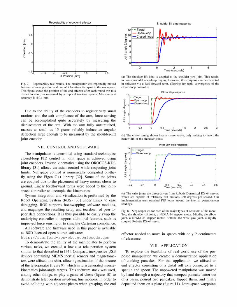
Fig. 7. Repeatability test results. The manipulator was repeatedly movedbetween a home position and one of 8 locations far apart in the workspace.This figure shows the position of the end effector after each round-trip to adistant location, as measured by an optical tracking system. Measurementaccuracy is ±0.1 mm.
Due to the ability of the encoders to register very smallmotions and the soft compliance of the arm, force sensingcan be accomplished quite accurately by measuring thedisplacement of the arm. With the arm fully outstretched,masses as small as 15 grams reliably induce an angulardeflection large enough to be measured by the shoulder-liftjoint encoder.
VII. CONTROL AND SOFTWARE
The manipulator is controlled using standard techniques:closed-loop PID control in joint space is achieved usingjoint encoders. Inverse kinematics using the OROCOS-KDLlibrary [31] allows cartesian control while respecting jointlimits. Nullspace control is numerically computed on-the-fly using the Eigen C++ library [32]. Some of the jointsare coupled due to the placement of heavy motors closer toground. Linear feedforward terms were added to the joint-space controller to decouple the kinematics.
System integration and visualization is performed by theRobot Operating System (ROS) [33] under Linux to easedebugging. ROS supports hot-swapping software modules,and maganges the resulting setup and teardown of peer-to-peer data connections. It is thus possible to easily swap theunderlying controller to support additional features, such asimproved force sensing or to simulate Cartesian compliance.
All software and firmware used in this paper is availableas BSD-licensed open-source software:http://stanford-ros-pkg.googlecode.com
To demonstrate the ability of the manipulator to performvarious tasks, we created a low-cost teleoperation systemsimilar to that described in [34]. Compact, inexpensive USBdevices containing MEMS inertial sensors and magnetome-ters were affixed to a shirt, allowing estimation of the postureof the teleoperator (figure 9), which in turn generated inverse-kinematics joint-angle targets. This software stack was used,among other things, to play a game of chess (figure 10) todemonstrate teleoperation involving fine motions. In order toavoid colliding with adjacent pieces when grasping, the end
−2 0 2 4 6
0
2
4
6
8
10
12
Time (seconds)
Jo
int
an
gle
(d
eg
ree
s)
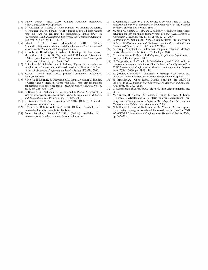
Shoulder lift step response
TargetOpen−loopClosed−loop
(a) The shoulder lift joint is coupled to the shoulder yaw joint. This resultsin non-sinusoidal open-loop ringing. However, this coupling can be correctedin software via a feed-forward term, allowing for rapid convergence of theclosed-loop controller.
−1 −0.5 0 0.5 1 1.5 2 2.5 3
0
5
10
15
Time (seconds)
Join
t angle
(degre
es)
Elbow step response
TargetOpen−loopClosed−loop
(b) The elbow tuning shown here is conservative, only seeking to match thebandwidth of the shoulder joints.
−0.2 −0.1 0 0.1 0.2 0.3 0.4 0.5
0
2
4
6
8
10
12
Time (seconds)
Join
t an
gle
(d
egre
es)
Wrist yaw step response
Target
Closed−loop
(c) The wrist joints are direct-driven from Robotis Dynamixel RX-64 servos,which are capable of relatively fast motions 360 degrees per second. Ourimplementation uses standard PID loops around the internal potentiometerreadings.
Fig. 8. Step responses for each of the major types of actuators of the robot.Top, the shoulder-lift joint, a NEMA-34 stepper motor. Middle, the elbowjoint, a NEMA-23 stepper motor. Bottom, the wrist yaw joint, a rigidlycoupled Robotis RX-64 servo.
effector needed to move in spaces with only 2 centimetersof clearance.
VIII. APPLICATIONTo explore the feasibility of real-world use of the pro-
posed manipulator, we created a demonstration applicationof cooking pancakes. For this application, we affixed anend effector consisting of a distal roll axis connected to aspatula and spoon. The unpowered manipulator was movedby hand through a trajectory that scooped pancake batter outof a basin, poured two pancakes, flipped them, and finallydeposited them on a plate (figure 11). Joint-space waypoints

Fig. 9. Low-cost MEMS inertial sensors affixed to the teleoperator’s torso,upper arm, lower arm, and hand to estimate desired end-effector positions.
Fig. 10. Playing chess via teleoperation.
Fig. 11. Demonstration task: making pancakes (see video).
were recorded at key locations. The intrinsic compliance ofthe manipulator simplifed the necessary programming: onlymoving-setpoint control with linear joint-space interpolationwas necessary in order to obtain reliable autonomous taskcompletion, as shown in the video supplied with this paper.During the scraping operation, firm contact between thespatula and the grill surface was maintained by virtue of theseries-elastic shoulder and elbow combined with the com-pliance of the spatula. As a result, neither high-bandwidthcontrol nor accurate force/torque sensors were required atthe end effector.
IX. CONCLUSIONS AND FUTURE WORK
A. Conclusions
We have presented the design of a low-cost robotic armuseful for manipulation research. In gearing, we traded offthe space and complexity of a timing belt and zero-backlashcable drive circuit in place of the cost of an expensivegearhead. In motor selection, we used stepper motors fortheir high torque at low speeds, in exchange for a highly-reduced brushless or brushed motor. These design tradeoffswere chosen for the envisioned target application of robotsinteracting with unstructured environments such as a typicalhome or workplace, where the safety of intrinsic mechanicalcompliance is an important design consideration. The cost-controlling tradeoffs described in this paper were made asan effort towards designing affordable compliant manipula-tors, an area of research which, to date, has received littleattention, and which we propose could have a large impacton the speed of adoption of robots into typical homes andworkplaces.
B. Future Work
We intend to continue simplifying the mechanisms in-troduced in this paper, with the goal of enabling low-costproduction of reasonable-performance manipulators. We in-tend to continue exploring low-cost fabrication techniques forfunctional components, and expect that many, if not all, struc-tural components could be made with low-cost metalworkingtechniques, allowing fast assembly and easy maintenance, aswell as reduced weight and increased stiffness.
REFERENCES
[1] C. Christensen, The innovator’s dilemma: when new technologiescause great firms to fail. Harvard Business Press, 1997.
[2] B. Rooks, “The harmonious robot,” Industrial Robot: An InternationalJournal, vol. 33, no. 2, pp. 125–130, 2006.
[3] Barrett Technology, Inc., “WAM Arm,” 2010. [Online]. Available:http://www.barrett.com/robot/products-arm-specifications.htm
[4] Meka Robotics, “A2 compliant arm,” 2009. [Online]. Available:http://www.mekabot.com/arm.html
[5] R. Brooks, C. Breazeal, M. Marjanovic, B. Scassellati, andM. Williamson, “The Cog project: Building a humanoid robot,”Computation for metaphors, analogy, and agents, pp. 52–87, 1999.
[6] A. Edsinger-Gonzales and J. Weber, “Domo: A force sensing hu-manoid robot for manipulation research,” in 2004 4th IEEE/RASInternational Conference on Humanoid Robots, 2004, pp. 273–291.
[7] E. Torres-Jara, “Obrero: A platform for sensitive manipulation,” in2005 5th IEEE-RAS International Conference on Humanoid Robots,2005, pp. 327–332.
[8] H. Iwata, S. Kobashi, T. Aono, and S. Sugano, “Design of anthro-pomorphic 4-dof tactile interaction manipulator with passive joints,”Intelligent Robots and Systems, 2005 (IROS 2005), pp. 1785 – 1790,Aug. 2005.
[9] J. Pratt, B. Krupp, and C. Morse, “Series elastic actuators for highfidelity force control,” Industrial Robot: An International Journal,vol. 29, no. 3, pp. 234–241, 2002.
[10] M. Zinn, B. Roth, O. Khatib, and J. Salisbury, “A new actuationapproach for human friendly robot design,” The international journalof robotics research, vol. 23, no. 4-5, p. 379, 2004.
[11] D. Shin, I. Sardellitti, and O. Khatib, “A hybrid actuation approachfor human-friendly robot design,” in IEEE Int. Conf. on Robotics andAutomation (ICRA 2008), Pasadena, USA, 2008, pp. 1741–1746.
[12] K. Wyrobek, E. Berger, H. der Loos, and J. Salisbury, “Towards apersonal robotics development platform: Rationale and design of anintrinsically safe personal robot,” in Proc. IEEE Int. Conf. on Roboticsand Automation, 2008, pp. 2165–2170.
[13] Willow Garage, “PR2,” 2010. [Online]. Available: http://www.willowgarage.com/pages/pr2/specs
[14] G. Hirzinger, N. Sporer, A. Albu-Schaffer, M. Hahnle, R. Krenn,A. Pascucci, and M. Schedl, “DLR’s torque-controlled light weightrobot III- Are we reaching the technological limits now?” inProceedings- IEEE International Conference on Robotics and Automa-tion, vol. 2, 2002, pp. 1710–1716.
[15] Schunk, “7-DOF LWA Manipulator,” 2010. [Online].Available: http://www.schunk-modular-robotics.com/left-navigation/service-robotics/components/manipulators.html
[16] R. Ambrose, H. Aldridge, R. Askew, R. Burridge, W. Bluethmann,M. Diftler, C. Lovchik, D. Magruder, and F. Rehnmark, “Robonaut:NASA’s space humanoid,” IEEE Intelligent Systems and Their Appli-cations, vol. 15, no. 4, pp. 57–63, 2000.
[17] J. Stuckler, M. Schreiber, and S. Behnke, “Dynamaid, an anthropo-morphic robot for research on domestic service applications,” in Proc.of the 4th European Conference on Mobile Robots (ECMR), 2009.
[18] KUKA, “youbot arm,” 2010. [Online]. Available: http://www.kuka-youbot.com
[19] F. Pierrot, E. Dombre, E. Degoulange, L. Urbain, P. Caron, S. Boudet,J. Gariepy, and J. Megnien, “Hippocrate: a safe robot arm for medicalapplications with force feedback,” Medical Image Analysis, vol. 3,no. 3, pp. 285–300, 1999.
[20] E. Dombre, G. Duchemin, P. Poignet, and F. Pierrot, “Dermarob: asafe robot for reconstructive surgery,” IEEE Transactions on Roboticsand Automation, vol. 19, no. 5, pp. 876–884, 2003.
[21] S. Robotics, “R17 5-axis robot arm,” 2010. [Online]. Available:http://www.strobotics.com/
[22] , “The Old Robots Web Site,” 2010. [Online]. Available: http://www.theoldrobots.com/robot-robot.html
[23] Colne Robotics, “Armdroid,” 1981. [Online]. Available: http://www.senster.com/alex zivanovic/armdroid/index.htm
[24] R. Chandler, C. Clauser, J. McConville, H. Reynolds, and J. Young,Investigation of inertial properties of the human body. NTIS, NationalTechnical Information Service, 1975.
[25] M. Zinn, O. Khatib, B. Roth, and J. Salisbury, “Playing it safe: A newactuation concept for human-friendly robot design,” IEEE Robotics &Automation Magazine, vol. 11, no. 2, pp. 12–21, 2004.
[26] G. Pratt and M. Williamson, “Series elastic actuators,” in Proceedingsof the IEEE/RSJ International Conference on Intelligent Robots andSystems (IROS-95), vol. 1, 1995, pp. 399–406.
[27] A. Kumpf, “Explorations in low-cost compliant robotics,” Master’sthesis, Massachusetts Institute of Technology, 2007.
[28] Y. Bar-Cohen and C. Breazeal, Biologically inspired intelligent robots.Society of Photo Optical, 2003.
[29] N. Tsagarakis, M. Laffranchi, B. Vanderborght, and D. Caldwell, “Acompact soft actuator unit for small scale human friendly robots,” inIEEE International Conference on Robotics and Automation Confer-ence (ICRA), 2009, pp. 4356–4362.
[30] M. Quigley, R. Brewer, S. Soundararaj, V. Pradeep, Q. Le, and A. Ng,“Low-cost Accelerometers for Robotic Manipulator Perception.”
[31] H. Bruyninckx, “Open Robot Control Software: the OROCOSProject,” in IEEE International Conference on Robotics and Automa-tion, 2001, pp. 2523–2528.
[32] G. Guennebaud, B. Jacob, et al., “Eigen v3,” http://eigen.tuxfamily.org,2010.
[33] M. Quigley, B. Gerkey, K. Conley, J. Faust, T. Foote, J. Leibs,E. Berger, R. Wheeler, and A. Ng, “ROS: an open-source Robot Oper-ating System,” in Open-source Software Workshop of the InternationalConference on Robotics and Automation, 2009.
[34] N. Miller, O. Jenkins, M. Kallmann, and M. Mataric, “Motion capturefrom inertial sensing for untethered humanoid teleoperation,” in 20044th IEEE/RAS International Conference on Humanoid Robots, 2004,pp. 547–565.