Monticello NRC EXAM Scenario 1
180
Monticello NRC EXAM Scenario 1 Appendix D Scenario Outline Form ES-D-1 Facility: Monticello Scenario No.: NRC Scenario 1 Op-Test No.: MNGP 2010 Examiners: ____________________________ Operators: _____________________________ ____________________________ _____________________________ ____________________________ _____________________________ Initial Conditions: 100% Power HPCI is Inoperable #12 CRD Pump Inop Turnover: Shift RBCCW Pumps Event No. Malf. No. Event Type* Event Description 1 None N BOP BOP shifts RBCCW pumps. 2 NI13C I ATC/SRO APRM #3 fails upscale. With the updated nuclear instrumentation, a ½ scram does not occur. Tech Specs are referenced and APRM #3 is Bypassed. (TS) 3 RC02 02-S17-04 (Ovrd) C BOP/SRO Inadvertent RCIC start. The trip pushbutton will also fail to shutdown RCIC, requiring an alternate shutdown method (TS) (ABN) 4 04-A2S70-04 (Ovrd) C BOP/SRO EPR Failure. The MPR starts controlling but must be adjusted lower to maintain Core Thermal Power within limits. (ABN) 5 CH01_65 C ATC/SRO Rod Drift Out (42-27). The rod is inserted, declared inoperable, and disarmed. (ABN) 6 TU03 G, H, & I R ATC/SRO Turbine bearing vibrations begin to increase. Rapid Power Reduction is performed in response. (ABN) 7 RR01B M Crew A small leak begins inside the Drywell. EOP 1200 is performed with no further challenges. EOP 1100 is entered. Alternate Level Control actions are performed when the Feed Pumps and RCIC fail. Emergency Depressurization is performed and RPV level is restored with low pressure systems. (N)ormal, (R)eactivity, (I)nstrument, (C)omponent, (M)ajor ES-301-4 Quantitative attributes: Total Malfunctions (5-8): 6 Malfunction(s) after EOP (1-2): 1 Abnormal Events (2-4): E3, E4, E5, E6 Major Transient(s) /E-Plan entry (1-2): E7 EOPs (1-2): 1100 & 1200 EOP Contingencies (0-2): 2 (ALC, ED) Critical Tasks (2-3): 2 ES-301-5 Quantitative attributes: BOP Normal: E1 ATC Reactivity (1 per set): E6 BOP I/C (4 / set): E3& 4 ATC I/C (4 / set): E2 & 5 SRO-I I/C (4 / set inc 2 as ATC): E2, 3, 4, & 5 SRO Tech Spec (2 per set): E2, E3, E5 ALL Major Transients (2 per set): 1
Transcript of Monticello NRC EXAM Scenario 1

Monticello NRC EXAM Scenario 1
Appendix D Scenario Outline Form ES-D-1
Facility: Monticello Scenario No.: NRC Scenario 1 Op-Test No.: MNGP 2010
Examiners: ____________________________ Operators: _____________________________ ____________________________ _____________________________ ____________________________ _____________________________
Initial Conditions: 100% Power HPCI is Inoperable #12 CRD Pump Inop
Turnover: Shift RBCCW Pumps
Event No.
Malf. No. Event Type*
Event Description
1 None N
BOP
BOP shifts RBCCW pumps.
2
NI13C I
ATC/SRO
APRM #3 fails upscale. With the updated nuclear instrumentation, a ½ scram does not occur. Tech Specs are referenced and APRM #3 is Bypassed. (TS)
3
RC02 02-S17-04 (Ovrd)
C
BOP/SRO
Inadvertent RCIC start. The trip pushbutton will also fail to shutdown RCIC, requiring an alternate shutdown method (TS) (ABN)
4
04-A2S70-04
(Ovrd)
C
BOP/SRO
EPR Failure. The MPR starts controlling but must be adjusted lower to maintain Core Thermal Power within limits. (ABN)
5
CH01_65 C
ATC/SRO
Rod Drift Out (42-27). The rod is inserted, declared inoperable, and disarmed. (ABN)
6
TU03 G, H, & I R
ATC/SRO
Turbine bearing vibrations begin to increase. Rapid Power Reduction is performed in response. (ABN)
7
RR01B M
Crew A small leak begins inside the Drywell. EOP 1200 is performed with no further challenges. EOP 1100 is entered. Alternate Level Control actions are performed when the Feed Pumps and RCIC fail. Emergency Depressurization is performed and RPV level is restored with low pressure systems.
(N)ormal, (R)eactivity, (I)nstrument, (C)omponent, (M)ajor
ES-301-4 Quantitative attributes: Total Malfunctions (5-8): 6 Malfunction(s) after EOP (1-2): 1 Abnormal Events (2-4): E3, E4, E5, E6 Major Transient(s) /E-Plan entry (1-2): E7 EOPs (1-2): 1100 & 1200 EOP Contingencies (0-2): 2 (ALC, ED) Critical Tasks (2-3): 2
ES-301-5 Quantitative attributes: BOP Normal: E1 ATC Reactivity (1 per set): E6 BOP I/C (4 / set): E3& 4 ATC I/C (4 / set): E2 & 5 SRO-I I/C (4 / set inc 2 as ATC): E2, 3, 4, & 5 SRO Tech Spec (2 per set): E2, E3, E5 ALL Major Transients (2 per set): 1

QF-1075-02 Rev. 3 (FP-T-SAT-75)
Retention: Life of Plant Retain in: Training Program File Form retained in accordance with record retention schedule identified in FP-G-RM-01.
SIMULATOR EXERCISE GUIDE (SEG)
SITE: MONTICELLO SEG # ILT-SS-11E
SEG TITLE: 2010 ILT NRC 1 REV. # 0
PROGRAM: INITIAL LICENSE TRAINING #: MT-ILT
COURSE: NRC EXAM #: M-8119
TOTAL TIME: 1.5 HOURS
Additional site-specific signatures may be added as desired.
Developed by:
Instructor Date
Reviewed by:
Instructor
(Simulator Scenario Development Checklist.)
Date
Validated by:
Validation Lead Instructor
(Simulator Scenario Validation Checklist.)
Date
Approved by:
Training Supervision Date

QF-1075-02 Rev. 3 (FP-T-SAT-75) Page 3 of 180 ILT-SS-11E, 2010 ILT NRC 1, Rev. 0
Retention: Life of Plant Retain in: Training Program File Form retained in accordance with record retention schedule identified in FP-G-RM-01.
Guide Requirements
Goal of Training:
ILT NRC Exam
Learning Objectives:
1. Demonstrate the ability to predict and/or monitor changes in
parameters associated with operating system controls for the
appropriate tasks.
2. Demonstrate the ability to correctly use procedures to correct,
control, or mitigate the consequences of normal and abnormal
operations for the appropriate tasks.
3. Demonstrate the ability to monitor automatic operations of the
systems to ensure proper operation for the appropriate tasks.
4. Demonstrate the ability to manually operate and/or monitor systems
in the control room in accordance with approved procedures for the
appropriate tasks.
5. Demonstrate the ability to complete administrative requirements, as
necessary, in order to operate the plant for the appropriate tasks.
6. Demonstrate knowledge of and ability to implement shift
supervision duties as they relate to crew operations for the
appropriate tasks.
7. Given a degrading or improving plant condition or event,
demonstrate the ability to: (CRS)
a. Evaluate trends that may result in equipment damage or reduction
in plant safety.
b. Ensure proper diagnosis of plant problems by monitoring and
interpreting data (information from panel indications).
c. Evaluate and diagnose challenges to Critical Plant Parameters.
d. Evaluate events and accidents.
Prerequisites: 1. Completion of MT-ILT Training Program
Training Resources:
1. Full Scope Simulator
2. 3139 (Control Room Shift Turnover Checklist)
3. 3140 (Shift Supervisors Office Shift Turnover Checklist)
4. Simulator Driver
5. Simulator Phone Talker
6. Operations Representative
7. Evaluators
References: 1. B.01.03-05 (CRD)
2. B.02.05-05 (RBCCW)
3. B.05.01.02-05 (POWER RANGE NEUTRON MONITORING)

QF-1075-02 Rev. 3 (FP-T-SAT-75) Page 4 of 180 ILT-SS-11E, 2010 ILT NRC 1, Rev. 0
Retention: Life of Plant Retain in: Training Program File Form retained in accordance with record retention schedule identified in FP-G-RM-01.
4. C.4-B.01.03.C (CONTROL ROD DRIFTING)
5. C.4-B.04.01.F (LEAK INSIDE PRIMARY CONTAINMENT)
6. C.4-B.05.09-B (MAIN STEAM PRESSURE REGULATOR
FAILURE CAUSING INCREASED PRESSURE)
7. C.4-A (REACTOR SCRAM)
8. C.4-F (RAPID POWER REDUCTION)
9. C.4-G (INADVERTENT ECCS INITIATION SIGNAL)
10. C.4-K (IMMEDIATE REACTOR SHUTDOWN)
11. C.5-1100 (RPV CONTROL)
12. C.5-1200 (PRIMARY CONTAINMENT CONTROL)
13. C.5-2002 (EMERGENCY RPV DEPRESSURIZATION)
14. C.5-3203 (USE OF ALTERNATE INJECTION SYSTEMS FOR
RPV MAKEUP)
15. C.5-3204 (RPV MAKEUP WITH CRD)
16. C.5-3502 (CONTAINMENT SPRAY)
17. C.5-3503 (DEFEAT DRYWELL COOLER TRIPS)
18. C.6-004-A-14 (RCIC LOW FLOW)
19. C.6-004-B-35 (DRYWELL-TORUS HI PRESS)
20. C.6-005-A-22 (APRM UPSC/INOP TRIP)
21. C.6-005-A-27 (ROD DRIFT)
22. C.6-007-B-15 (EPR TROUBLE)
23. C.6-007-B-33 (TURBINE VIBRATION HIGH)
24. Tech Specs Section 3.3
25. Tech Specs Section 3.5
Commitments: 1. None
Evaluation Method:
ILT NRC Exam
Operating Experience:
Not Applicable / ILT Exam

QF-1075-02 Rev. 3 (FP-T-SAT-75) Page 5 of 180 ILT-SS-11E, 2010 ILT NRC 1, Rev. 0
Retention: Life of Plant Retain in: Training Program File Form retained in accordance with record retention schedule identified in FP-G-RM-01.
Related PRA Information:
Initiating Event with Core Damage Frequency Contribution:
Internal Flood (36.8%)
Station Blackout (27.4%)
Loss of High Pressure Injection (13.4%)
ATWS (11.4%)
LOCA (7.7%)
Loss of Low Pressure Injection (2.0%)
LOCA Outside Containment (0.6%)
Loss of Containment Heat Removal (0.4%)
Important Components:
EDGs
HPCI
RCIC
Scram
Feed/Cond
SRV (When stuck open)
SRVs
Instrument AC
Fire System (for RPV Injection)
4160 VAC
Important Operator Actions with Task Number:
CR314.101, Emergency Depressurize
CR305.108, Recover Offsite Power
CR305.105/6, SBO-Recover an EDG
CR305.121, Align #13 EDG to Essential MCCs
CR314.126, Vent Containment
CR259.127, Control Feedwater following a Scram
CR314.112, Control Reactor Water Level during an ATWS
CR211.106, Inject with SBLC during an ATWS

QF-1075-02 Rev. 3 (FP-T-SAT-75) Page 6 of 180 ILT-SS-11E, 2010 ILT NRC 1, Rev. 0
Retention: Life of Plant Retain in: Training Program File Form retained in accordance with record retention schedule identified in FP-G-RM-01.
TASKS ASSOCIATED WITH SIMULATOR EXERCISE(S):
Shift Manager Tasks:
None
SRO Tasks:
SS201.000 Control Rod Drive System Duty Area 6, 7
SS215.000 Nuclear Instrumentation Duty Area 6, 7
SS299.351 Apply administrative requirements for Tech Spec
Section 3.3 and Bases to Instrumentation
6, 7
SS299.353 Apply administrative requirements for Tech Spec
Section 3.5 and Bases to ECCS and RCIC
6, 7
SS304.193 Implement RPV control 6, 7
SS304.194 Implement primary containment control 6, 7
SS304.198 Implement Emergency RPV Depressurization 6, 7
SS314.106 Supervise use of alternate injection systems for RPV
Makeup
6, 7
SS314.107 Supervise RPV Makeup with CRD 6, 7
SS314.119 Supervise Containment Spray 6, 7
SS314.120 Supervise defeat drywell cooler trips 6, 7
SS315.101 Supervise response to a reactor scram 6, 7
SS315.117 Supervise response to a leak inside primary
containment
6, 7
SS315.123 Supervise response to increasing pressure caused by main steam pressure regulator failure
6, 7
SS315.159 Supervise rapid power reduction 6, 7
SS315.160 Supervise the response to inadvertent ECCS
initiation.
6, 7
SS315.164 Supervise immediate reactor shutdown 6, 7

QF-1075-02 Rev. 3 (FP-T-SAT-75) Page 7 of 180 ILT-SS-11E, 2010 ILT NRC 1, Rev. 0
Retention: Life of Plant Retain in: Training Program File Form retained in accordance with record retention schedule identified in FP-G-RM-01.
RO Tasks:
CR200.146 Perform the procedure for a Reactor Scram 1-5
CR200.162 Perform the procedure for a leak inside primary
containment
1-5
CR200.167 Perform the procedure for main steam pressure
regulator failure causing increasing pressure
1-5
CR200.203 Perform the procedure for rapid power reduction. 1-5
CR200.204 Perform the procedure for inadvertent ECCS
initiation.
1-5
CR200.208 Perform the procedure for immediate reactor
shutdown.
1-5
CR201.116 Respond to Inadvertent Control Rod Withdrawal/Rod
Drift Out
1-5
CR208.102 Transfer to the standby RBCCW Pump 1-5
CR215.134 Resetting APRM/RBM Trip and alarm indications 1-5
CR215.136 Resetting 2-of-4 Voter Trip Indications 1-5
CR304.102 Perform actions associated with RPV control 1-5
CR304.103 Perform actions associated with Primary containment
control
1-5
CR314.101 Perform actions associated with Emergency
Depressurization
1-5
CR314.110 Use alternate injection systems for RPV Makeup 1-5
CR314.111 Perform actions associated with RPV Makeup with
CRD
1-5
CR314.123 Perform actions associated with Containment Spray 1-5
CR314.124 Defeat Drywell Cooler Trips 1-5
STA Tasks:
None

QF-1075-02 Rev. 3 (FP-T-SAT-75) Page 8 of 180 ILT-SS-11E, 2010 ILT NRC 1, Rev. 0
Retention: Life of Plant Retain in: Training Program File Form retained in accordance with record retention schedule identified in FP-G-RM-01.
QUANTITATIVE ATTRIBUTES (Use this form for Evaluations only.)
Malfunctions:
Before EOP Entry:
1. APRM #3 fails upscale
2. Inadvertent RCIC start.
3. EPR Failure
4. Rod Drift Out
5. Elevated Turbine Vibes
After EOP Entry:
1. Both Feed Pumps trip.
2. RCIC cannot be restarted
Abnormal Events:
1. Inadvertent RCIC start.
2. EPR Failure
3. Rod Drift Out
4. Rapid Power Reduction for elevated Turbine vibes
Major Transients:
1. A small LOCA inside Drywell combined with the loss of most high pressure injection.
Critical Tasks:
1. CT-16: Inhibit ADS to avoid auto initiation that would result in a violation of cooldown rate or a loss of adequate
core cooling.
2. CT-22: When RPV water level cannot be maintained >-149”, Emergency Depressurize the reactor.
QF-1075-02 Rev. 3 (FP-T-SAT-75) Page 9 of 180 ILT-SS-11E, 2010 ILT NRC 1, Rev. 0
Retention: Life of Plant Retain in: Training Program File Form retained in accordance with record retention schedule identified in FP-G-RM-01.
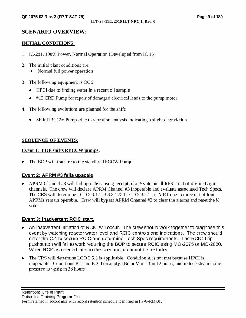
SCENARIO OVERVIEW:
INITIAL CONDITIONS:
1. IC-281, 100% Power, Normal Operation (Developed from IC 15)
2. The initial plant conditions are:
Normal full power operation
3. The following equipment is OOS:
HPCI due to finding water in a recent oil sample
#12 CRD Pump for repair of damaged electrical leads to the pump motor.
4. The following evolutions are planned for the shift:
Shift RBCCW Pumps due to vibration analysis indicating a slight degradation
SEQUENCE OF EVENTS:
Event 1: BOP shifts RBCCW pumps.
The BOP will transfer to the standby RBCCW Pump.
Event 2: APRM #3 fails upscale
APRM Channel #3 will fail upscale causing receipt of a ½ vote on all RPS 2 out of 4 Vote Logic
channels. The crew will declare APRM Channel #3 inoperable and evaluate associated Tech Specs.
The CRS will determine LCO 3.3.1.1, 3.3.2.1 & TLCO 3.3.2.1 are MET due to three out of four
APRMs remain operable. Crew will bypass APRM Channel #3 to clear the alarms and reset the ½
vote.
Event 3: Inadvertent RCIC start.
An inadvertent initiation of RCIC will occur. The crew should work together to diagnose this event by watching reactor water level and RCIC controls and indications. The crew should enter the C.4 to secure RCIC and determine Tech Spec requirements. The RCIC Trip pushbutton will fail to work requiring the BOP to secure RCIC using MO-2075 or MO-2080. When RCIC is needed later in the scenario, it cannot be restarted.
The CRS will determine LCO 3.5.3 is applicable. Condition A is not met because HPCI is
inoperable. Conditions B.1 and B.2 then apply. (Be in Mode 3 in 12 hours, and reduce steam dome
pressure to ≤psig in 36 hours).

QF-1075-02 Rev. 3 (FP-T-SAT-75) Page 10 of 180 ILT-SS-11E, 2010 ILT NRC 1, Rev. 0
Retention: Life of Plant Retain in: Training Program File Form retained in accordance with record retention schedule identified in FP-G-RM-01.
Event 4: Electric Pressure Regulator (EPR) Fails.
The EPR fails. That automatically places the Mechanical Pressure Regulator (MPR) in control.
However, the MPR is set a little too high and must be readjusted to restore reactor pressure and
power to normal.
Event 5: Control Rod begins to Drift Out,
Control Rod 42-27 begins to drift out from position 12. The ATC/SRO respond per C.4-B.01.03.C.
Outward rod movement can be stopped by driving the rod in and holding the rod movement switch
in that position until the Reactor Bldg Operator disarms the rod.
The CRS must declare the rod inoperable.
Event 6: Rapid Power Reduction for elevated Turbine vibes
Vibrations begin to rise on Main Turbine Bearing #8, followed by Bearings 7 and 9. The crew
performs Rapid Power Reduction but the vibration levels continue to rise toward 15 Mils. The crew
then manually scrams the reactor and trips the Turbine.
The Crew performs the procedure for Reactor Scram and enters EOP 1100 when RPV water level
drops below 9 inches.
Event 7: Small LOCA inside Drywell
During the scram recovery, both Feedwater pumps trip and cannot be restarted. Alternate Level
Control Actions are performed due to the loss of high pressure injection systems.
A small leak inside the Drywell also reduces RPV inventory. EOP 1200 actions can be successfully
performed to mitigate Primary Containment problems.
Emergency Depressurization must be performed to allow Core Spray and RHR pumps to restore
RPV water level.

QF-1075-02 Rev. 3 (FP-T-SAT-75) Page 11 of 180 ILT-SS-11E, 2010 ILT NRC 1, Rev. 0
Retention: Life of Plant Retain in: Training Program File Form retained in accordance with record retention schedule identified in FP-G-RM-01.
NOTE: Table may be modified as needed to include all scenario time-line items
SCENARIO TIME-LINE:
SEQ SEQUENCE OF EVENTS / INSTRUCTOR NOTES CREW
POS EXPECTED STUDENT RESPONSES
1. INITIAL CONDITIONS (IC):
a. IC: 281
b. Mode: 1
c. Power: 100%
d. Generator: 604 Mwe
e. Xcel system condition is GREEN
f. Plant CDF is YELLOW
g. River temp is 56°F and no towers are in service
h. Outside temp is 60°F
i. HPCI is out of service due to finding water in a recent oil sample
j. #12 CRD Pump is out of service for repair of damaged electrical leads to the pump motor
k. Possible vibration issue with #11 RBCCW Pump.
2. SIMULATOR SET UP
a. Set the plant initial conditions per the Initial conditions under the Scenario Overview, Initial Conditions, and Manual Settings.
b. Enter the malfunctions, remotes, overrides and event triggers per the “Simulator Input Summary”.
c. Control Room and Shift Supervisor turnover checklists should be provided with the scenario IC.
d. Core Damage Frequency (CDF) should be updated on the status board.
e. Tech Spec Required Actions should be updated on the status board.

QF-1075-02 Rev. 3 (FP-T-SAT-75) Page 12 of 180 ILT-SS-11E, 2010 ILT NRC 1, Rev. 0
Retention: Life of Plant Retain in: Training Program File Form retained in accordance with record retention schedule identified in FP-G-RM-01.
SCENARIO TIME-LINE:
SEQ SEQUENCE OF EVENTS / INSTRUCTOR NOTES CREW
POS EXPECTED STUDENT RESPONSES
3. COMPLETE TURNOVER:
a. Review applicable current Unit Status #12 CRD Pump for repair of damaged electrical leads to the pump
motor.
Shift RBCCW Pumps due to vibration analysis indicating a slight
degradation
b. Review relevant At-Power Risk status
c. Review current LCOs not met and Action Requirements
TS 3.5.1 Condition J, HPCI inoperable due to finding water in a
recent oil sample
Condition J.1, immediately verify RCIC is operable is met.
Condition J.2, restore HPCI, in day 2 of 14
d. Verify crew performs walk down of control boards and reviews turnover checklists.
e. Plant Staffing The following support is available:
Normal Weekday Night Shift
Operations: Normal crew compliment only based on actual crew staffing.
Maintenance: Available as needed or requested.
Engineering: Available as needed or requested.
Management: Available as needed or requested.
f. Planned Shift Activities
1) Shift to the Standby RBCCW

QF-1075-02 Rev. 3 (FP-T-SAT-75) Page 13 of 180 ILT-SS-11E, 2010 ILT NRC 1, Rev. 0
Retention: Life of Plant Retain in: Training Program File Form retained in accordance with record retention schedule identified in FP-G-RM-01.
SCENARIO TIME-LINE:
SEQ SEQUENCE OF EVENTS / INSTRUCTOR NOTES CREW
POS EXPECTED STUDENT RESPONSES
4. SHIFT BRIEF
a. Role Play as necessary. Turbine Building status: CRS Leads the Shift Brief
1). 5 Condensate demins in service. ATC/BOP Participate in Shift Brief
2). C highest @ 6.0 psid.
3). All systems in Turbine building are normal.
b. Role Play as necessary. Rx Building status:
4). Maintenance is standing by for RBCCW Pump shift
5). HPCI and 12 CRD Pump are tagged out for maintenance.
6). All other systems in the Rx bldg are normal. CRS Crew assumes the duty.

QF-1075-02 Rev. 3 (FP-T-SAT-75) Page 14 of 180 ILT-SS-11E, 2010 ILT NRC 1, Rev. 0
Retention: Life of Plant Retain in: Training Program File Form retained in accordance with record retention schedule identified in FP-G-RM-01.
SCENARIO TIME-LINE:
SEQ SEQUENCE OF EVENTS / INSTRUCTOR NOTES CREW
POS EXPECTED STUDENT RESPONSES
Event 1 5. BOP shifts RBCCW pumps
a. Role play and complete necessary actions as an in-plant operator:
BOP Transfers to the standby RBCCW Pump per B.02.05-05. E.1
1) Standing by to shift RBCCW Pumps Station an operator at RBCCW Pumps
2) The #12 pump suction and discharge valves are open prior to starting
Establish communications
3) The pump and motor operate normally after starting
Insure #12 RBCCW Pump suction and discharge valves are
open
Note: the position of the #11 RBCCW Pump discharge valve is transparent to the control Room
Start #12 RBCCW Pump
Confirm proper operation with in-plant operator
4) When directed, wait 1 minute and report that #11 RBCCW Pump discharge valve has been closed
Direct in-plant operator to slowly close the #11 RBCCW
Pump discharge valve
1. When the #11 RBCCW Pump discharge valve is
closed, immediately trip the pump
5) When directed, wait 1 minute and report that the #11 RBCCW Pump discharge valve has been reopened.
2. Direct the in-plant operator to re-open the #11
RBCCW Pump discharge valve
Place the #11 RBCCW Pump switch in Auto-standby

QF-1075-02 Rev. 3 (FP-T-SAT-75) Page 15 of 180 ILT-SS-11E, 2010 ILT NRC 1, Rev. 0
Retention: Life of Plant Retain in: Training Program File Form retained in accordance with record retention schedule identified in FP-G-RM-01.
SCENARIO TIME-LINE:
SEQ SEQUENCE OF EVENTS / INSTRUCTOR NOTES CREW
POS EXPECTED STUDENT RESPONSES
Event 2 6. APRM #3 fails upscale
a. When directed by the Lead Examiner, insert MANUAL TRIGGER 1
Key Parameter Response: APRM Channel #3 High or INOP Red
indicating light lit; APRM Channel #3 recorder upscale high
1) Verify Malfunction NI13C goes active. Key Expected Alarms: C05-A-22 (APRM UPSC/INOP Trip), C05-A-
3 (ROD WITHDRAW BLOCK), C05-A14 (APRM ALARM)
Auto Actions: ½ Vote trip for APRM 3 on all 2 out of 4 Vote Logic
Channels
ATC Responds to Annunciators C05-A-3, 14 & 22 and notifies CRS.
Determines the trip signal by pressing the APRM or APRM
ODA “TRIP STATUS” softkey
Determines that APRM Channel 3 is upscale and Inoperable
Verifies Automatic actions initiated.
b. When operator goes to Panel C-37 to observe status of 2 of 4 Voter Modules #1, 2 & 4, inform him these voters indicate the same as Voter Module #3 for APRM Channel #3. Voter Modules 1, 2 & 4 are not modeled.
Verifies each 2 of 4 Voter Module APRM UPSC/INOP
INPUT SATUS LEDs is ON for APRM #3
Rod Block initiated
INPUT STATUS LEDs activated on the 2 of 4 Voter for
APRM UPSC/INOP, OPRM DIDA/INOP, and OPRM
CDA/INOP
Determines the INOP signal by pressing the APRM or APRM
ODA “INOP STATUS” softkey; Critical Self Test Fault
ATC Bypasses APRM Ch #3 as directed by the CRS.
CREW Notifies Plant Engineering.

QF-1075-02 Rev. 3 (FP-T-SAT-75) Page 16 of 180 ILT-SS-11E, 2010 ILT NRC 1, Rev. 0
Retention: Life of Plant Retain in: Training Program File Form retained in accordance with record retention schedule identified in FP-G-RM-01.
SCENARIO TIME-LINE:
SEQ SEQUENCE OF EVENTS / INSTRUCTOR NOTES CREW
POS EXPECTED STUDENT RESPONSES
CRS Acknowledges alarm receipt. Conducts validation and verification of
APRM status and declares APRM Channel #3 inoperable. Consults
Tech Spec LCO 3.3.1.1, Table 3.3.1.1-1 and LCO 3.3.2.1, Table
3.3.2.1-1 and determines LCO 3.3.1.1 & 3.3.2.1 continue to be MET
due to 3 APRM channels remain operable. Also refers to TRM and
determines TLCO 3.3.2.1 is MET.
c. Role Play plant support personnel as necessary to acknowledge report.
CRS Directs OATC to bypass APRM Channel #3.
QF-1075-02 Rev. 3 (FP-T-SAT-75) Page 17 of 180 ILT-SS-11E, 2010 ILT NRC 1, Rev. 0
Retention: Life of Plant Retain in: Training Program File Form retained in accordance with record retention schedule identified in FP-G-RM-01.
SCENARIO TIME-LINE:
SEQ SEQUENCE OF EVENTS / INSTRUCTOR NOTES CREW
POS EXPECTED STUDENT RESPONSES
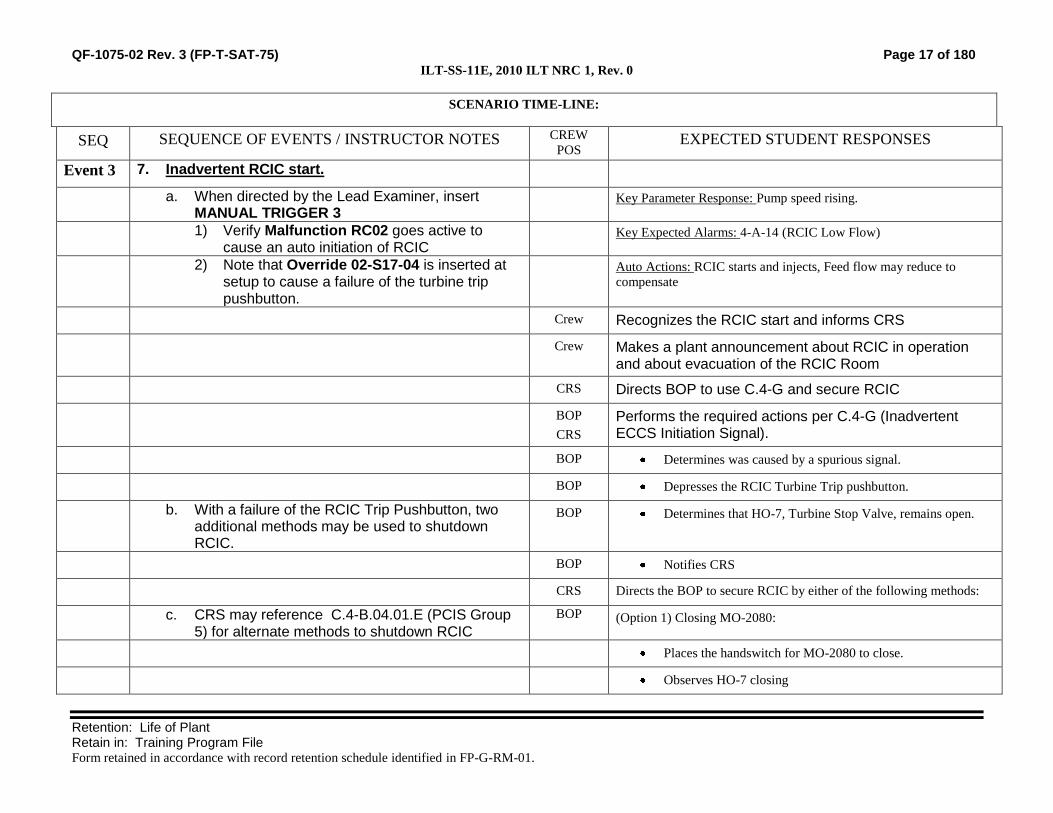
Event 3 7. Inadvertent RCIC start.
a. When directed by the Lead Examiner, insert MANUAL TRIGGER 3
Key Parameter Response: Pump speed rising.
1) Verify Malfunction RC02 goes active to cause an auto initiation of RCIC
Key Expected Alarms: 4-A-14 (RCIC Low Flow)
2) Note that Override 02-S17-04 is inserted at setup to cause a failure of the turbine trip pushbutton.
Auto Actions: RCIC starts and injects, Feed flow may reduce to
compensate
Crew Recognizes the RCIC start and informs CRS
Crew Makes a plant announcement about RCIC in operation and about evacuation of the RCIC Room
CRS Directs BOP to use C.4-G and secure RCIC
BOP
CRS
Performs the required actions per C.4-G (Inadvertent ECCS Initiation Signal).
BOP Determines was caused by a spurious signal.
BOP Depresses the RCIC Turbine Trip pushbutton.
b. With a failure of the RCIC Trip Pushbutton, two additional methods may be used to shutdown RCIC.
BOP Determines that HO-7, Turbine Stop Valve, remains open.
BOP Notifies CRS
CRS Directs the BOP to secure RCIC by either of the following methods:
c. CRS may reference C.4-B.04.01.E (PCIS Group 5) for alternate methods to shutdown RCIC
BOP (Option 1) Closing MO-2080:
Places the handswitch for MO-2080 to close.
Observes HO-7 closing

QF-1075-02 Rev. 3 (FP-T-SAT-75) Page 18 of 180 ILT-SS-11E, 2010 ILT NRC 1, Rev. 0
Retention: Life of Plant Retain in: Training Program File Form retained in accordance with record retention schedule identified in FP-G-RM-01.
SCENARIO TIME-LINE:
SEQ SEQUENCE OF EVENTS / INSTRUCTOR NOTES CREW
POS EXPECTED STUDENT RESPONSES
Verifies that RCIC speed lowers when the valve has closed
and reports to the CRS that RCIC has been shutdown.
BOP (Option 2) For closing the Steam line isolation valves:
8. MO-2076 and MO-2078 will reopen if closed due to receiving an open signal from the initiation signal.
Closes MO-2075
Verifies one of the steam line isolations remain closed
Verifies RCIC speed lowers when the steam line isolates
Notifies CRS that RCIC has been shutdown
Crew Notifies Management, RP and Single Point of Contact.
CRS References TS 3.5.3 to assess RCIC operability
a. Role Play plant support personnel as necessary to acknowledge report.
CRS Determines RCIC is INOP (but available in an emergency)
Condition A is not met because HPCI is inoperable.
Conditions B.1 and B.2 then apply. (Be in Mode 3 in 12
hours, and reduce steam dome pressure to ≤150 psig in 36
hours)
References TS 3.5.1 to assess the combination of HPCI and RCIC both
inoperable
Determines Condition N applies because the completion time of
Condition J not met (Be in Mode 3 in 12 hours, and reduce
steam dome pressure to ≤150 psig in 36 hours)
Event 4 9. EPR Failure
a. When directed by the lead evaluator, INSERT MANUAL TRIGGER 5
Key Parameter Response: RPV Pressure rises which also raises Core
Thermal Power
1) Verify Override 04-A2S70-04 goes active to stop the EPR
Key Expected Alarms: C07-B-15 EPR TROUBLE

QF-1075-02 Rev. 3 (FP-T-SAT-75) Page 19 of 180 ILT-SS-11E, 2010 ILT NRC 1, Rev. 0
Retention: Life of Plant Retain in: Training Program File Form retained in accordance with record retention schedule identified in FP-G-RM-01.
SCENARIO TIME-LINE:
SEQ SEQUENCE OF EVENTS / INSTRUCTOR NOTES CREW
POS EXPECTED STUDENT RESPONSES
2) Note: the MPR setpoint is raised slightly at setup
Auto Actions: The MPR begins to control pressure
BOP Responds to C07-B-15, EPR TROUBLE and notifies the CRS
Verifies that the MPR assumes stable steam pressure control
Depress the ELECTRIC PRESSURE REG STOP Pushbutton
Recognizes that the EPR TROUBLE annunciator does not reset
CRS
BOP
Performs C.4-B.05.09-B Main Steam Pressure Regulator Failure
Causing Increased Pressure
BOP/ATC Monitor Reactor Pressure
Identifies that Reactor pressure increased slightly when the EPR
failed
Adjusts the MPR to maintain Reactor Dome Pressure per C.1
(Startup Procedures)
b. Role Play plant support personnel as necessary to acknowledge report.
BOP
CRS
Initiate an investigation to determine the cause of the EPR failure
Event 5 10. Rod Drift Out 1) When the OATC is not observing C-05 and
when directed by the lead evaluator, INSERT MANUAL TRIGGER 7
Key Parameter Response: Rod 42-27 indication on the full core
display starts changing from 12 to 48 and its ROD DRIFT indicating
light will be on.
a) Verify Override 03-S72-24 goes active to give rod 42-27 an out signal.
Key Expected Alarms: C05-A27 ROD DRIFT
Auto Actions: Reactor power increases
ATC Responds to C05-A27 ROD DRIFT and notifies the CRS
If any control rod is moving and movement was not intended,
enter C.4-B.01.03.C

QF-1075-02 Rev. 3 (FP-T-SAT-75) Page 20 of 180 ILT-SS-11E, 2010 ILT NRC 1, Rev. 0
Retention: Life of Plant Retain in: Training Program File Form retained in accordance with record retention schedule identified in FP-G-RM-01.
SCENARIO TIME-LINE:
SEQ SEQUENCE OF EVENTS / INSTRUCTOR NOTES CREW
POS EXPECTED STUDENT RESPONSES
Identify that only one rod is drifting (manual scram is not
necessary)
Momentarily place ROD SELECT POWER SWITCH 3A-S1 to
OFF and then back to ON to deselect the drifting rod
Identifies that rod continues to withdraw
Reselects the drifting rod and uses the normal or emergency insert
and maintain the control rod at position 00
Verifies proper CRD operating parameters
2) Role Play Nuclear Engineering Supervisor as necessary
BOP
CRS Verify that core thermal power and thermal limits have not been
exceeded
3) Role Play Reactor Bldg Operator as necessary and, when directed to disarm Rod 42-27 activate MANUAL TRIGGER 9
Notify Nuclear Engineering Supervisor
Refer to B.01.03-05.H, Inadvertent Control Rod Withdrawal/Rod
Drift Out
a) Verify Malfunction CH01_65 reactivates and deletes in 1 second
o Directs the Reactor Bldg Operator to disarm or isolate
Rod 42-27
b) Verify Remote Function CH15_65 goes to 0 to effect electrically disarming.
CRS Supervises actions for a Rod drift
c) Wait 2 minutes and report Rod 42-27 has been disarmed (or isolated as directed) and proceed to the next Event.
Event 6 11. Rapid Power Reduction for elevated Turbine vibes Key Parameter Response: Rising vibrations for Bearings 7, 8, & 9 on
VR-1716 at C-07, Computer Alarm at 7 mils
a. When directed by the Lead Examiner, insert MANUAL TRIGGER 11.
Key Expected Alarms: C07B-33 TURBINE VIBRATION HIGH
1) Verify Malfunctions TU03G, TU03H and TU03I begin to ramp in.
Auto Actions: None
BOP Responds to Annunciator C07B-33 and informs CRS
Note: The first annunciator will activate in approximately 2 minutes.
BOP Monitor Turbine vibration as indicated on VR-1716 (Panel C-07).

QF-1075-02 Rev. 3 (FP-T-SAT-75) Page 21 of 180 ILT-SS-11E, 2010 ILT NRC 1, Rev. 0
Retention: Life of Plant Retain in: Training Program File Form retained in accordance with record retention schedule identified in FP-G-RM-01.
SCENARIO TIME-LINE:
SEQ SEQUENCE OF EVENTS / INSTRUCTOR NOTES CREW
POS EXPECTED STUDENT RESPONSES
b. Role Play Equipment Operator or in-plant personnel as necessary:
CREW Verify that annunciator was not caused by maintenance or other
activities on the Turbine floor that could cause a false vibration
indication.
1) Confirm that there are no activities on the Turbine floor that could cause false readings.
CRS IF sustained Turbine Generator vibration levels are 10 Mils or
higher,
THEN refer to C.3 (SHUTDOWN PROCEDURES),
AND remove the Turbine-Generator from service.
2) Also report that vibrations can be felt in the Turbine floor.
IF Rapid Power Reduction is deemed necessary
THEN perform C.4-F (RAPID POWER REDUCTION),
as required to reduce vibration levels
CRS Supervises Rapid Power Reduction
ATC Performs Rapid Power Reduction per C.4.F
ATC Reduces recirculation flow
ATC Does NOT go below 35Mlb/hr
c. When the Turbine trips, verify Event Trigger 28 goes True
Crew IF sustained Turbine vibration levels approach 15 Mils,
THEN perform the following:
1) Verify the severity of Malfunctions TU03G, TU03H and TU03I begin to ramp down and the malfunctions delete in 2 minutes
ATC o Reduce recirculation flow to minimum.
ATC o Initiate a manual Reactor scram
BOP o Manually trip the Turbine Generator.
Event 7 12. ATC Actions for Reactor Scram ATC Actions per C.4-A (Reactor Scram):
a. Verify Event Trigger 26 goes True when the Mode Switch is taken to SHUTDOWN
Place Mode Switch in SHUTDOWN.
1) Verify that Malfunction RC03 (RCIC Trip) goes active
Verify all Control Rods are inserted to or beyond position 04.
2) Verify that Malfunctions FW16A & FW16B (Feed Pump Trips) go active
Provides scram script to CRS when RPV level drops to less
than 9” EOP Entry Condition

QF-1075-02 Rev. 3 (FP-T-SAT-75) Page 22 of 180 ILT-SS-11E, 2010 ILT NRC 1, Rev. 0
Retention: Life of Plant Retain in: Training Program File Form retained in accordance with record retention schedule identified in FP-G-RM-01.
SCENARIO TIME-LINE:
SEQ SEQUENCE OF EVENTS / INSTRUCTOR NOTES CREW
POS EXPECTED STUDENT RESPONSES
3) Verify that Malfunction RR01B (Small Line Break) goes active after a 2 minute delay and begins to increase to 15% severity on a 2 minute ramp.
Controls Reactor water level between +9 and +48 inches.
When reactor water level starts to increase:
o Place CV-6-13 Manual Loading Station Low Flow
Valve in AUTO set between 15 and 20 inches
o Close both Main FW Reg Valves
o Close MO-1133 and MO-1134 (HP Feedwater Line
Block valves
o Verify CV-6-13 is closed when RPV level reaches
+15 to +20 inches
Monitor Reactor Power
o Insert SRM and IRM detectors.
o Switch recorders from APRM to IRM.
o Range down on IRMs as necessary.
Verify SDV Vent and Drain Valves closed.
Event 7 13. BOP Actions for Reactor Scram BOP Starts performance of Part B of C.4.A
Announce over the plant paging system that a Reactor Scram
has occurred.
Open Main Generator output bkrs 8N4 & 8N5.
Trip the Main Turbine.
Verify the Generator Field Breaker Open.
Start the Turbine Aux Oil Pump.
Verify Turbine Exhaust Hood Sprays in service.

QF-1075-02 Rev. 3 (FP-T-SAT-75) Page 23 of 180 ILT-SS-11E, 2010 ILT NRC 1, Rev. 0
Retention: Life of Plant Retain in: Training Program File Form retained in accordance with record retention schedule identified in FP-G-RM-01.
SCENARIO TIME-LINE:
SEQ SEQUENCE OF EVENTS / INSTRUCTOR NOTES CREW
POS EXPECTED STUDENT RESPONSES
Verify Main Steam Pressure Control or Low-Low Set is
controlling Reactor Pressure.
CRS Supervise response to reactor scram
Event 7 14. EOP 1100 Actions
CRS Directs performance of C.5-1100 (RPV Control)
a. Role Play in-plant operators as necessary. There is no apparent cause for the loss of the Feed Pumps.
ATC Recognizes the loss of both Feed Pumps
Attempts to restart the Feed Pumps
Notifies the CRS
CT-16 Inhibit ADS to avoid auto initiation that would result in a violation of cooldown rate or a loss of adequate core cooling.
CRS Direct Alternate Level control Actions
ATC Inhibit ADS
b. When directed to close CRD-168, insert MANUAL TRIGGER 13.
Performs RPV makeup with CRD: Directs in-plant operator
to close CRD-168 (Pump Bypass Isol)
1) Verify Remote Function CH34 goes to 1 (Closed)
Starts a SBLC pump for injection. (C.5-3203)
2) Wait 2 minutes and report that CRD-168 is closed.
o Verifies injection

QF-1075-02 Rev. 3 (FP-T-SAT-75) Page 24 of 180 ILT-SS-11E, 2010 ILT NRC 1, Rev. 0
Retention: Life of Plant Retain in: Training Program File Form retained in accordance with record retention schedule identified in FP-G-RM-01.
SCENARIO TIME-LINE:
SEQ SEQUENCE OF EVENTS / INSTRUCTOR NOTES CREW
POS EXPECTED STUDENT RESPONSES
o Adequately monitors and reports RPV level and
Pressure, both values and trends.
EVALUATOR NOTE: The crew may deem RCIC unavailable due to the earlier inadvertent start. To manually initiate the steam lines must be reopened. In either case RCIC will NOT start and inject.
Crew o Recognizes that RCIC is available.
ATC/BOP Attempts to manually start RCIC
Informs the CRS that RCIC will not start
Event 7 15. LOCA inside Drywell
BOP Reports Drywell pressure rising
Reports EOP entry conditions.
o DW pressure, DW Temp and Torus temp
Note: Containment Spray/Cooling actions may not be taken if the crew prioritizes RPV water level.
CRS Directs performance of C.5-1200 (PC Control)
Start Torus sprays
Start all available Torus cooling
Spray the Drywell
BOP Performs C.5 1200 actions
Places Torus Sprays in service per C.5-3502:
o Verifies RHR Pumps running
o Takes Cont Spray/Cooling LPCI Initiation Bypass (A/B) to BYPASS

QF-1075-02 Rev. 3 (FP-T-SAT-75) Page 25 of 180 ILT-SS-11E, 2010 ILT NRC 1, Rev. 0
Retention: Life of Plant Retain in: Training Program File Form retained in accordance with record retention schedule identified in FP-G-RM-01.
SCENARIO TIME-LINE:
SEQ SEQUENCE OF EVENTS / INSTRUCTOR NOTES CREW
POS EXPECTED STUDENT RESPONSES
o Opens MO-2006, 2010, & 2008 (A Loop) or Opens MO-2007, 2011, & 2009 (B Loop)
o Verifies LPCI Inject Outboard Valves are closed; MO-2012 and MO-2013.
BOP Initiates Containment Cooling
o RHRSW Outlet valve controller set 20%
o Place HX Bypass in CLOSE
o ECCS Load Shed to MANUAL OVERRIDE
Event 7
(con’t)
16. LOCA Primary Containment Control (Drywell): o Start RHRSW Pump(s)
o Adjust flow to 3500 gpm per pump
o Start room cooler
BOP Reports Drywell pressure rising
Reports EOP entry conditions.
o DW pressure, DW Temp and Torus temp
CRS Directs performance of C.5-1200 (PC Control)
Start all available Drywell cooling
Spray the Drywell (If Drywell Pressure exceeds 12 psig)
BOP Performs C.5 1200 actions
Start all available drywell cooling (C.5-3503)
o Place all D/W fan control switches to OFF

QF-1075-02 Rev. 3 (FP-T-SAT-75) Page 26 of 180 ILT-SS-11E, 2010 ILT NRC 1, Rev. 0
Retention: Life of Plant Retain in: Training Program File Form retained in accordance with record retention schedule identified in FP-G-RM-01.
SCENARIO TIME-LINE:
SEQ SEQUENCE OF EVENTS / INSTRUCTOR NOTES CREW
POS EXPECTED STUDENT RESPONSES
o Open Knife switch KS3100
o Verify fan inlet dampers are in AUTO
o Place all D/W fan control switches to ON
o OPEN associated fan disch dampers
BOP Initiates Drywell Spray (C.5-3502)
o Open Drywell Spray Outboard MO-2020 (2021)
o Open Drywell Spray Inboard MO-2022 (2023)
o Close Torus Cooling MO-2008 (2009)
Event 7 17. Alternate RPV Level Control /Blowdown:
CRS Verifies two or more Injection Subsystems lined up with pumps running.
CT-22 When RPV water level cannot be maintained >-149”, Emergency Depressurize the reactor.
When RPV level is < -126 inches and prior to -149 inches, directs
performance of C.5-2002 (Emergency RPV Depressurization)
Verifies Torus level > -5.9 ft.
Directs opening of all 3 ADS SRVs.
Directs RPV Level restoration
BOP Verifies that both Core Spray Subsystems and LPCI Pumps are available for injection
a. Verify Event Trigger 24 goes True when A SRV Handswitch is taken to Open
BOP/ATC Opens 3 ADS SRVs
1) Verify that Malfunction RR03B (Large Line Break) goes active at 5% severity.
Monitor and report RPV level values and trends

QF-1075-02 Rev. 3 (FP-T-SAT-75) Page 27 of 180 ILT-SS-11E, 2010 ILT NRC 1, Rev. 0
Retention: Life of Plant Retain in: Training Program File Form retained in accordance with record retention schedule identified in FP-G-RM-01.
SCENARIO TIME-LINE:
SEQ SEQUENCE OF EVENTS / INSTRUCTOR NOTES CREW
POS EXPECTED STUDENT RESPONSES
BOP Controls RPV injection from RHR.
o Throttles MO-2012.
BOP Controls RPV injection from Core Spray.
o Throttles MO-1753 and MO-1754
ATC Controls RPV injection from the Condensate system.
18. SCENARIO TERMINATION
a. The scenario may be terminated when:
1) Emergency Depressurization has been performed
2) RPV water level is recovered above TAF.
b. The scenario may be also terminated at the discretion of lead instructor/evaluator
Crew: Remain in simulator for potential questions from evaluator.
c. End the scenario by placing the simulator in FREEZE.
Crew: No discussion of scenario or erasing of procedure marking is allowed.

QF-1075-02 Rev. 3 (FP-T-SAT-75) Page 28 of 180 ILT-SS-11E, 2010 ILT NRC 1, Rev. 0
Retention: Life of Plant Retain in: Training Program File Form retained in accordance with record retention schedule identified in FP-G-RM-01.
SIMULATOR INPUT SUMMARY
Code Description Event Trigger Delay Ramp Initial Value Final Value
MALFUNCTIONS (Allow Tracking Off)
NI13C APRM CHANNEL #3 FULLSCALE 1 None None 1 (True)
RC02 RCIC Auto Initiation (Inadvertent) 3 None None 1 (True)
CH01_65 Rod Drift Out (42-27)
(Inserted and deleted in 1 second)
9 None None 1 (True)
TU03G Shaft Bearing High Vibrations #7 11 None 00:05:00 0 40
TU03H Shaft Bearing High Vibrations #8 11 None 00:05:00 0 50
TU03I Shaft Bearing High Vibrations #9 11 None 00:05:00 0 40
TU03G Shaft Bearing High Vibrations #7 28 None 00:03:00 40 0
TU03H Shaft Bearing High Vibrations #8 28 None 00:03:00 50 0
TU03I Shaft Bearing High Vibrations #9 28 None 00:03:00 40 0
RC03 RCIC Trip 26 None None 1 (True)
FW16A Reactor Feedpump #11 Trip 26 None None 1 (True)
FW16B Reactor Feedpump #12 Trip 26 None None 1 (True)
RR01B (LOCA) Small Line Break Recirc on #12 26 00:02:00 00:02:00 0 15
RR03B (LOCA) Large Line Break Recirc on #12 24 None None 0 5
CH01_65 Rod Drift Out (42-27) 30 None None 1 (True)

QF-1075-02 Rev. 3 (FP-T-SAT-75) Page 29 of 180 ILT-SS-11E, 2010 ILT NRC 1, Rev. 0
Retention: Life of Plant Retain in: Training Program File Form retained in accordance with record retention schedule identified in FP-G-RM-01.
SIMULATOR INPUT SUMMARY
Code Description Event Trigger Delay Ramp Initial Value Final Value
REMOTES
CH15_65 Control Rod (42-27) Electrically Disarmed 9 None None 0 (Disarm)
CH34 CRD-168, CH Header to CST Return Line 13 None None 1
(Closed)
OVERRIDES
02-S17-04 A520P31-31 – RCIC Turbine Trip HS 30 None None False False
01-DS148-02 A531P29-24 HPCI OIL PUMP GREEN LAMP 30 None None Off Off
01-DS149-02 A531P29-23 HPCI OIL PUMP RED LAMP 30 None None Off Off
01-S068-02 A520P30-22 AUX OIL PUMP HS - AUTO 30 None None False False
01-S068-04 A520P30-21 AUX OIL PUMP HS - RUN 30 None None False False
03-DS083-02 P28-49 #12 CRDH Pump Green Lamp 30 None None Off Off
03-S56-02 P13-23 12 CRD Pump-Stop 30 None None False True
03-S56-01 P13-20 12 CRD Pump-Start 30 None None False False
03-S72-02 P14-10 Rod Notch “OUT” (Auto deletes in 2 seconds)
7 None None False True
04-A2S70-04 A521P31-40 Elec Press Regulator Stop-PB 5 None None False True

QF-1075-02 Rev. 3 (FP-T-SAT-75) Page 30 of 180 ILT-SS-11E, 2010 ILT NRC 1, Rev. 0
Retention: Life of Plant Retain in: Training Program File Form retained in accordance with record retention schedule identified in FP-G-RM-01.
Event Trigger Definitions:
Code Description Event Trigger
ZD_HS4C(1) “A” SRV Handswitch taken to OPEN 24
ZD_S1SHD Reactor Mode Switch taken to SHUTDOWN 26
tcvcv(1)==0 #1 TCV closed (Turbine Trip) 28
Manual Settings:
1. Reset to IC 281.
a. If necessary, IC 281 can be recreated as follows:
o Reset to IC 15, (100% Power).
o At C-07, give the MPR a momentary raise signal.
o Take the HPCI Aux Oil Pump Handswitch to PTL.
o Establish Event Triggers and Commands per the Simulator Input Summary.
2. Manually activate event Trigger 30 to establish the initial conditions for the scenario.
3. Hang Caution tags for HPCI and for the #12 CRD Pump.
4. Verify Event Trigger Definitions:
a. Event Trigger 28 is used to ramp down and then delete the turbine vibrations when the turbine trips.
b. Event Trigger 26 is used to initiate the LOCA, RCIC trip, and loss of Feed Pumps the Mode Switch is taken to Shutdown.
c. Event Trigger 24 is used to increase the size of the LOCA when Emergency Depressurization is performed.
5. Verify the Malfunctions match the Simulator Input Summary.
6. Verify the Remotes match the Simulator Input Summary.
7. Verify the Overrides match the Simulator Input Summary.
8. Verify the following conditions:
a. Rod 42-27 is selected
9. Perform the applicable sections of the SIMULATOR SETUP CHECKLIST.
10. Provide the following for the operating crew :
a. A scenario specific Form 3139, Control Room Shift Turnover Checklist
b. A scenario specific Form 3140, Shift Supervision Turnover Checklist

QF-1075-02 Rev. 3 (FP-T-SAT-75) Page 31 of 180 ILT-SS-11E, 2010 ILT NRC 1, Rev. 0
Retention: Life of Plant Retain in: Training Program File Form retained in accordance with record retention schedule identified in FP-G-RM-01.
Attach the following site-specific information as necessary:
Simulator Set-up Checklist (before and after training)
Pre-evaluation Brief Guide (for evaluations only)
Post-evaluation Critique (for evaluations only)
Turnover Log
Historical Record:
QF-1075-02 Rev. 3 (FP-T-SAT-75) Page 32 of 180 ILT-SS-11E, 2010 ILT NRC 1, Rev. 0
Retention: Life of Plant Retain in: Training Program File Form retained in accordance with record retention schedule identified in FP-G-RM-01.
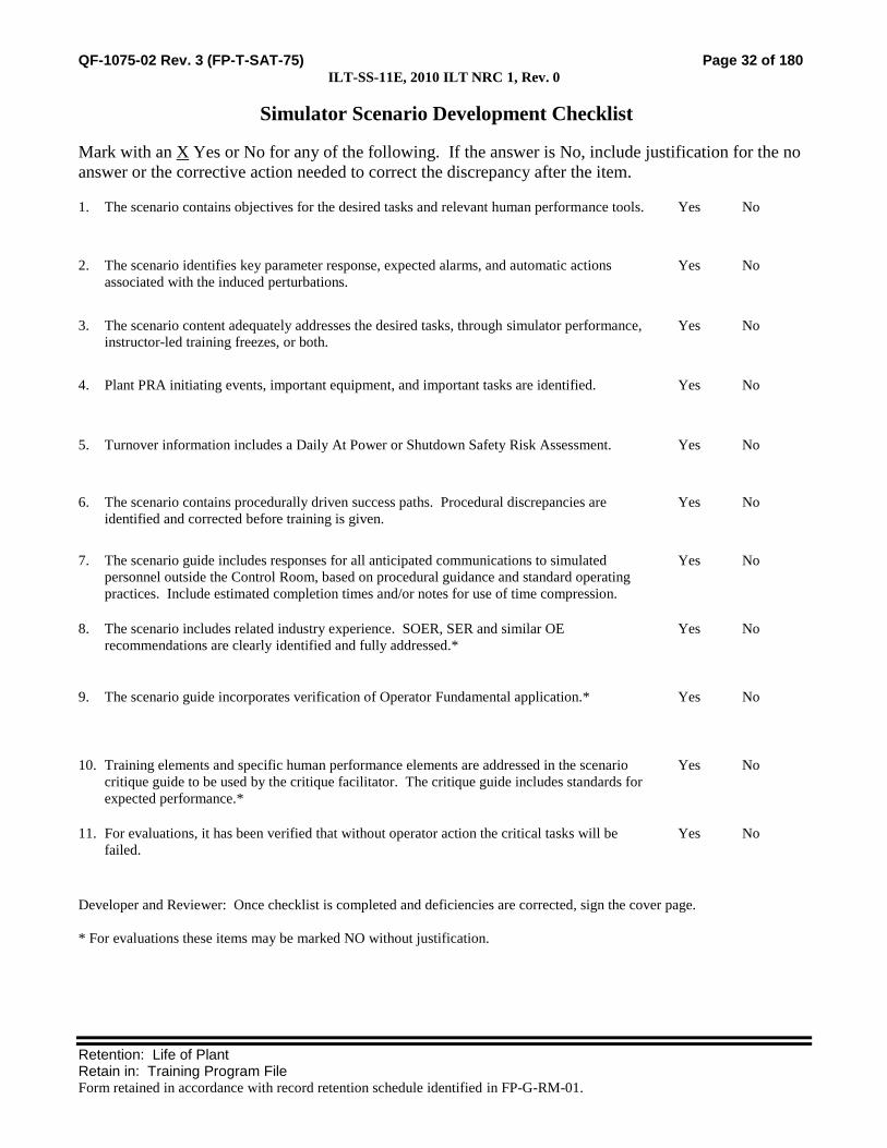
Simulator Scenario Development Checklist
Mark with an X Yes or No for any of the following. If the answer is No, include justification for the no
answer or the corrective action needed to correct the discrepancy after the item.
1. The scenario contains objectives for the desired tasks and relevant human performance tools. Yes No
2. The scenario identifies key parameter response, expected alarms, and automatic actions
associated with the induced perturbations.
Yes No
3. The scenario content adequately addresses the desired tasks, through simulator performance,
instructor-led training freezes, or both.
Yes No
4. Plant PRA initiating events, important equipment, and important tasks are identified. Yes No
5. Turnover information includes a Daily At Power or Shutdown Safety Risk Assessment. Yes No
6. The scenario contains procedurally driven success paths. Procedural discrepancies are
identified and corrected before training is given.
Yes No
7. The scenario guide includes responses for all anticipated communications to simulated
personnel outside the Control Room, based on procedural guidance and standard operating
practices. Include estimated completion times and/or notes for use of time compression.
Yes No
8. The scenario includes related industry experience. SOER, SER and similar OE
recommendations are clearly identified and fully addressed.*
Yes No
9. The scenario guide incorporates verification of Operator Fundamental application.* Yes No
10. Training elements and specific human performance elements are addressed in the scenario
critique guide to be used by the critique facilitator. The critique guide includes standards for
expected performance.*
Yes No
11. For evaluations, it has been verified that without operator action the critical tasks will be
failed.
Yes No
Developer and Reviewer: Once checklist is completed and deficiencies are corrected, sign the cover page.
* For evaluations these items may be marked NO without justification.

QF-1075-02 Rev. 3 (FP-T-SAT-75) Page 33 of 180 ILT-SS-11E, 2010 ILT NRC 1, Rev. 0
Retention: Life of Plant Retain in: Training Program File Form retained in accordance with record retention schedule identified in FP-G-RM-01.
Simulator Scenario Validation Checklist
Mark with an X Yes or No for any of the following. If the answer is No, include an explanation after the
item.
1. The desired initial condition(s) could be achieved.
Yes
No
2. All malfunctions and other instructor interface items were functional and responded to
support the simulator scenario.
Yes
No
3. All malfunctions and other instructor interface items were initiated in the same
sequence described within the simulator scenario.
Yes
No
4. All applicable acceptance criteria were met for procedures that were used to support
the simulator scenario.
Yes
No
5. During the simulator scenario, observed changes corresponded to expected plant
response.
Yes
No
6. Did the scenario satisfy the learning or examination objectives without any significant
simulator performance issues, or deviations from the approved scenario sequence? If
learning objective(s) could not be satisfied, identify the objectives in the Simulator
Action Request
Yes
No
7. Evaluation: The simulator is capable of being used to satisfy learning or examination
objectives without exceptions, significant performance discrepancies, or deviation
from the approved scenario sequence.
Yes
No
Discrepancies noted (Check “none” or list items found) None
SMAR = Simulator Action Request
SMAR: SMAR: SMAR: SMAR:
Comments:
Validator: Sign the cover page only after noted discrepancies are corrected or compensatory actions are taken to ensure
quality training.

Monticello NRC EXAM Scenario 2
Appendix D Scenario Outline Form ES-D-1
Facility: Monticello Scenario No.: NRC Scenario 2 Op-Test No.: MNGP 2010
Examiners: ____________________________ Operators: _____________________________ ____________________________ _____________________________ ____________________________ _____________________________
Initial Conditions: 100% Power Turnover: #12 Service Water Pump Out of Service
Event No.
Malf. No. Event Type*
Event Description
1 None N
BOP
Shutdown of the Hydrogen Seal Oil Vacuum Pump
2 NI15A I
ATC/SRO
One channel of the RBM fails downscale. (TS)
3 SW01A I
BOP/SRO
Trip of the running RBCCW Pump, Manual Start of Standby Pump.(ABN) The momentary loss results in a loss of RWCU. (ABN)
4 None TS SRO
ECCS Room Fan found inoperable. (TS)
5 MC04B MC03
C
BOP/SRO
Loss of Main Condenser Vacuum due to SJAE controller problems. (ABN)
6 None R
ATC/SRO
Rapid Power Reduction is performed due to loss of vacuum. (ABN)
7 MC03 CH16 CH19
M Crew
An air leak into the condenser results in a severe loss of vacuum. When the Turbine trips, a Hydraulic ATWS is identified. EOP 1100 and 2007 are performed. Because the loss of vacuum results in the main condenser as a heat sink, Power Level Control must be performed and SRVs must be used to stabilize RPV Pressure. The scenario may be stopped when Control Rods have been inserted an/or RPV level has been restored.
8 SL01A/B C ATC
When SBLC injection is initiated, the first SBLC Pump selected will not start. The ATC must identify this failure and start the alternate SBLC Pump.
(N)ormal, (R)eactivity, (I)nstrument, (C)omponent, (M)ajor
ES-301-4 Quantitative attributes: Total Malfunctions (5-8): 5 Malfunction(s) after EOP (1-2): 2 Abnormal Events (2-4): 4 Major Transient(s) /E-Plan entry (1-2): E7 EOPs (1-2): 1100, 2007, 1200 EOP Contingencies (0-2): PLC Critical Tasks (2-3): 3
ES-301-5 Quantitative attributes: BOP Normal: E1 ATC Reactivity (1 per set): E6 BOP I/C (4 / set): E3 & 5 ATC I/C (4 / set): E2 & 8 SRO-I I/C (4 / set inc 2 as ATC): E2 & E5 SRO Tech Spec (2 per set): E2 &4 ALL Major Transients (2 per set): E7

QF-1075-02 Rev. 3 (FP-T-SAT-75)
Retention: Life of Plant Retain in: Training Program File Form retained in accordance with record retention schedule identified in FP-G-RM-01.
SIMULATOR EXERCISE GUIDE (SEG)
SITE: MONTICELLO SEG # ILT-SS-12E
SEG TITLE: 2010 ILT NRC 2 REV. # 0
PROGRAM: INITIAL LICENSE TRAINING #: MT-ILT
COURSE: NRC EXAM #: M-8119
TOTAL TIME: 1.5 HOURS
Additional site-specific signatures may be added as desired.
Developed by:
Instructor Date
Reviewed by:
Instructor
(Simulator Scenario Development Checklist.)
Date
Validated by:
Validation Lead Instructor
(Simulator Scenario Validation Checklist.)
Date
Approved by:
Training Supervision Date

QF-1075-02 Rev. 3 (FP-T-SAT-75) Page 36 of 180 ILT-SS-12E, 2010 ILT NRC 2, Rev. 0
Retention: Life of Plant Retain in: Training Program File Form retained in accordance with record retention schedule identified in FP-G-RM-01.
Guide Requirements
Goal of Training:
ILT NRC Exam
Learning Objectives:
8. Demonstrate the ability to predict and/or monitor changes in
parameters associated with operating system controls for the
appropriate tasks.
9. Demonstrate the ability to correctly use procedures to correct,
control, or mitigate the consequences of normal and abnormal
operations for the appropriate tasks.
10. Demonstrate the ability to monitor automatic operations of the
systems to ensure proper operation for the appropriate tasks.
11. Demonstrate the ability to manually operate and/or monitor systems
in the control room in accordance with approved procedures for the
appropriate tasks.
12. Demonstrate the ability to complete administrative requirements, as
necessary, in order to operate the plant for the appropriate tasks.
13. Demonstrate knowledge of and ability to implement shift
supervision duties as they relate to crew operations for the
appropriate tasks.
14. Given a degrading or improving plant condition or event,
demonstrate the ability to: (CRS)
a. Evaluate trends that may result in equipment damage or reduction
in plant safety.
b. Ensure proper diagnosis of plant problems by monitoring and
interpreting data (information from panel indications).
c. Evaluate and diagnose challenges to Critical Plant Parameters.
d. Evaluate events and accidents.
Prerequisites: 2. Completion of MT-ILT Training Program
Training Resources:
8. Full Scope Simulator
9. 3139 (Control Room Shift Turnover Checklist)
10. 3140 (Shift Supervisors Office Shift Turnover Checklist)
11. Simulator Driver
12. Simulator Phone Talker
13. Operations Representative
14. Evaluators
References: 26. B.03.01-05 (CORE SPRAY)
27. B.03.04-05 (RHR SYSTEM)
28. B.06.03.3-05 (GENERATOR HYDROGEN SEAL OIL)

QF-1075-02 Rev. 3 (FP-T-SAT-75) Page 37 of 180 ILT-SS-12E, 2010 ILT NRC 2, Rev. 0
Retention: Life of Plant Retain in: Training Program File Form retained in accordance with record retention schedule identified in FP-G-RM-01.
29. C.4-A (REACTOR SCRAM)
30. C.4-B.02.05.A (LOSS OF RBCCW FLOW)
31. C.4-B.06.03.A (DECREASING CONDENSER VACUUM)
32. C.4-F (RAPID POWER REDUCTION)
33. C.4-K (IMMEDIATE REACTOR SHUTDOWN)
34. C.5-1100 (RPV CONTROL)
35. C.5-1200 (PRIMARY CONTAINMENT CONTROL)
36. C.5-2007 (FAILURE TO SCRAM)
37. C.5-3101 (ALTERNATE ROD INSERTION)
38. C.5-3205 (TERMINATE AND PREVENT)
39. C.5-3301 (DEFEATING RPV LOW-LOW LEVEL ISOLATION
FOR MSIV CLOSURE)
40. C.5-3502 (CONTAINMENT SPRAY)
41. C.5-3503 (DEFEAT DRYWELL COOLER TRIPS)
42. C04-B-26 (CLEAN UP DEMINTEMP HI)
43. C.6 5-A-3 (ROD BLOCK)
44. C.6 5-A 43 (RBM DOWNSCALE / TROUBLE)
45. C.6 6-B-32 (RBCCW LOW DISCH PRESS)
46. Tech Specs Section 3.3
47. Tech Specs Section 3.5
48. Technical Requirements Manual 3.3
Commitments: 2. None
Evaluation Method:
ILT NRC Exam
Operating Experience:
Not Applicable / ILT Exam

QF-1075-02 Rev. 3 (FP-T-SAT-75) Page 38 of 180 ILT-SS-12E, 2010 ILT NRC 2, Rev. 0
Retention: Life of Plant Retain in: Training Program File Form retained in accordance with record retention schedule identified in FP-G-RM-01.
Related PRA Information:
Initiating Event with Core Damage Frequency Contribution:
Internal Flood (36.8%)
Station Blackout (27.4%)
Loss of High Pressure Injection (13.4%)
ATWS (11.4%)
LOCA (7.7%)
Loss of Low Pressure Injection (2.0%)
LOCA Outside Containment (0.6%)
Loss of Containment Heat Removal (0.4%)
Important Components:
EDGs
HPCI
RCIC
Scram
Feed/Cond
SRV (When stuck open)
SRVs
Instrument AC
Fire System (for RPV Injection)
4160 VAC
Important Operator Actions with Task Number:
CR314.101, Emergency Depressurize
CR305.108, Recover Offsite Power
CR305.105/6, SBO-Recover an EDG
CR305.121, Align #13 EDG to Essential MCCs
CR314.126, Vent Containment
CR259.127, Control Feedwater following a Scram
CR314.112, Control Reactor Water Level during an ATWS
CR211.106, Inject with SBLC during an ATWS

QF-1075-02 Rev. 3 (FP-T-SAT-75) Page 39 of 180 ILT-SS-12E, 2010 ILT NRC 2, Rev. 0
Retention: Life of Plant Retain in: Training Program File Form retained in accordance with record retention schedule identified in FP-G-RM-01.
TASKS ASSOCIATED WITH SIMULATOR EXERCISE(S):
Shift Manager Tasks:
None
SRO Tasks:
SS299.351 Apply administrative requirements for Tech Spec
Section 3.3 and Bases to Instrumentation
6, 7
SS299.354 Apply administrative requirements for Tech Spec
Section 3.5 and Bases to ECCS and RCIC
6, 7
SS299.362 Apply administrative requirements of the Technical
Requirements Manual
6, 7
SS304.193 Implement RPV control 6, 7
SS304.194 Implement primary containment control 6, 7
SS304.201 Implement the response for failure to scram 6, 7
SS314.101 Supervise alternate rod insertion 6, 7
SS314.108 Supervise terminate and prevent 6, 7
SS314.111 Supervise defeat of RPV Low-Low Level isolation
for MSIV closure
6, 7
SS314.119 Supervise containment Spray 6, 7
SS314.120 Supervise defeat of Drywell Cooler trips 6, 7
SS315.101 Supervise response to a reactor scram 6, 7
SS315.107 Supervise response to loss of RBCCW 6, 7
SS315.114 Supervise response to PCIS Group 3 6, 7
SS315.127 Supervise response to decreasing condenser vacuum 6, 7
SS315.159 Supervise rapid power reduction 6, 7
SS315.164 Supervise immediate reactor shutdown 6, 7

QF-1075-02 Rev. 3 (FP-T-SAT-75) Page 40 of 180 ILT-SS-12E, 2010 ILT NRC 2, Rev. 0
Retention: Life of Plant Retain in: Training Program File Form retained in accordance with record retention schedule identified in FP-G-RM-01.
RO Tasks:
CR200.146 Perform the procedure for Rx Scram 1-5
CR200.153 Perform the procedure for Loss of RBCCW Flow 1-5
CR200.159 Perform the procedure for PCIS Group 3 1-5
CR200.172 Perform the procedure for decreasing condenser
vacuum
1-5
CR200.203 Perform the procedure for rapid power reduction. 1-5
CR200.208 Perform the procedure for immediate reactor
shutdown
1-5
CR211.101 Operate the SBLC System 1-5
CR203.112 Place Torus Cooling in service during abnormal and
emergency conditions
1-5
CR215.000 Nuclear Instrumentation (Duty Area) 1-5
CR215.135 Resetting APRM/RBM Trip and alarm indications 1-5
CR245.131 Seal Oil Vacuum Pump P-69 Removal/Restoration
with the Plant On-line
1-5
CR304.102 Perform actions associated with RPV control 1-5
CR304.103 Perform actions associated with Primary containment
control
1-5
CR314.104 Perform actions associated with Failure to Scram 1-5
CR314.105 Perform actions associated with Alternate Rod
Insertion
1-5
CR314.112 Perform actions to terminate and prevent 1-5
CR314.115 Defeat RPV Low-Low Level isolation for MSIV
closure
1-5
CR314.123 Perform actions associated with Containment Spray 1-5
CR314.124 Defeat Drywell Cooler Trips 1-5
STA Tasks:
None

QF-1075-02 Rev. 3 (FP-T-SAT-75) Page 41 of 180 ILT-SS-12E, 2010 ILT NRC 2, Rev. 0
Retention: Life of Plant Retain in: Training Program File Form retained in accordance with record retention schedule identified in FP-G-RM-01.
QUANTITATIVE ATTRIBUTES (Use this form for Evaluations only.)
Malfunctions:
Before EOP Entry:
6. RBM Downscle
7. Trip of running RBCCW Pump
8. SJAE Controller
After EOP Entry:
3. First SBLC Pump fails to start
4. Turbine BPVs fail closed on complete loss of condenser vacuum
Abnormal Events:
5. Loss of RBCCW
6. Primary Containment Isolation Group 3
7. Loss of Main Condenser Vacuum
8. Rapid Power Reduction
Major Transients:
2. Hydraulic ATWS
Critical Tasks:
3. CT-43: When control rods fail to insert and heat is being added to the primary containment then inject SBLC.
4. CT-46: During failure to scram conditions with reactor power above 3%, terminate and prevent injection from
all sources except SBLC, RCIC, and CRD until level lowers to at least -33”.
5. CT-48: During failure to scram conditions with a critical reactor, insert control rods using one or more methods
contained within C.5-3101 to achieve reactor shutdown under all conditions.

QF-1075-02 Rev. 3 (FP-T-SAT-75) Page 42 of 180 ILT-SS-12E, 2010 ILT NRC 2, Rev. 0
Retention: Life of Plant Retain in: Training Program File Form retained in accordance with record retention schedule identified in FP-G-RM-01.
SCENARIO OVERVIEW:
INITIAL CONDITIONS:
5. IC 282, 100% %Power, Normal Ops
6. The following equipment is OOS
#12 Service Water Pump
7. The following evolutions are planned for the shift:
Secure the Hydrogen Seal Oil Vacuum Pump for inspection.
SEQUENCE OF EVENTS:
Event 1: Secure the Hydrogen Seal Oil Vacuum Pump
The BOP performs Seal Oil Vacuum Pump P-69 Removal/Restoration with the Plant On-line.
Event 2: One channel of the RBM fails downscale.
“A” RBM fails downscale. The ATC will address this problem by manipulating the relatively new Nuclear
instrumentation equipment and by eventually bypassing “A” RBM. The CRS will address Tech Specs for T.S.
3.3.2.1. (Note: Nuclear Instrumentation upgrade is a recent plant modification)
Event 3: Running RBCCW Pump Trip
The #11 RBCCW Pump trips and the #12 RBCCW Pump fails to auto start. When the BOP verifies
automatic actions and takes the #12 RBCCW Pump to START, it will start.
Event 4: ECCS Room Fan Found Inoperable
The Reactor Building Operator reports that he found a large fan belt hanging from V-AC-4 in the Division 2 RHR /Core
Spray Corner Room. Per the B Manuals for RHR and Core Spray, the loss of Room Cooling makes the affected Core
Spray and LPCI mode inoperable. The CRS applies TS 3.5.

QF-1075-02 Rev. 3 (FP-T-SAT-75) Page 43 of 180 ILT-SS-12E, 2010 ILT NRC 2, Rev. 0
Retention: Life of Plant Retain in: Training Program File Form retained in accordance with record retention schedule identified in FP-G-RM-01.
Event 5: Loss of Main Condenser Vacuum.
Alarms will indicate a loss of steam to the B SJAE. The BOP takes actions per the Abnormal
procedure for loss of Main Condenser Vacuum. In-plant operator actions can eventually bypass the
failed control valve to restore steam to the SJAE. The BOP can then reset the SJAE Isolation. (Note:
When this event was used for the ILT Exam in 2008 it exposed a procedural and training deficiency
that has since been corrected.)
Event 6: Rapid Power Reduction is performed due to loss of vacuum.
The CRS and OATC coordinate to lower Recirc Pump speeds as dictated by the Abnormal
procedure for loss of Main Condenser Vacuum.
Event 7: Turbine Trip, Hydraulic ATWS
An air leak causes a severe loss of Main Condenser Vacuum. The crew may manually scram the
reactor prior to the Turbine trip. Eventually, the loss of vacuum will close the Turbine Bypass
Valves, which will complicate RPV pressure Control during the ATWS.
After the reactor scram, a Hydraulic ATWS is identified. EOP 1100 and 2007 are performed.
Because the loss of vacuum results in the main condenser as a heat sink, Power Level Control must
be performed. The scenario may be stopped when Control Rods have been inserted and/or RPV
level has been restored.
Event 8: SBLC Initiation problems
When SBLC injection is initiated, the first SBLC Pump selected will not start. The ATC must
identify this failure and start the alternate SBLC Pump.

QF-1075-02 Rev. 3 (FP-T-SAT-75) Page 44 of 180 ILT-SS-12E, 2010 ILT NRC 2, Rev. 0
Retention: Life of Plant Retain in: Training Program File Form retained in accordance with record retention schedule identified in FP-G-RM-01.
NOTE: Table may be modified as needed to include all scenario time-line items
SCENARIO TIME-LINE:
SEQ SEQUENCE OF EVENTS / INSTRUCTOR NOTES CREW
POS EXPECTED STUDENT RESPONSES
19. INITIAL CONDITIONS (IC):
l. IC: 282
m. Mode: 1
n. Power: 100%
o. Generator: 604 Mwe
p. Xcel system condition is GREEN
q. Plant CDF is GREEN
r. River temp is 56°F and no towers are in service
s. Outside temp is 60°F
t. Hydrogen Seal Oil Vacuum Pump is running hot.
u. #12 Service Water Pump is out of service
20. SIMULATOR SET UP
f. Set the plant initial conditions per the Initial conditions under the Scenario Overview, Initial Conditions, and Manual Settings.
g. Enter the malfunctions, remotes, overrides and event triggers per the “Simulator Input Summary”.
h. Control Room and Shift Supervisor turnover checklists should be provided with the scenario IC.
i. Core Damage Frequency (CDF) should be updated on the status board.
j. Tech Spec Required Actions should be updated on the status board.

QF-1075-02 Rev. 3 (FP-T-SAT-75) Page 45 of 180 ILT-SS-12E, 2010 ILT NRC 2, Rev. 0
Retention: Life of Plant Retain in: Training Program File Form retained in accordance with record retention schedule identified in FP-G-RM-01.
SCENARIO TIME-LINE:
SEQ SEQUENCE OF EVENTS / INSTRUCTOR NOTES CREW
POS EXPECTED STUDENT RESPONSES
21. COMPLETE TURNOVER:
a. Review applicable current Unit Status (Green)
b. Review relevant At-Power Risk status (Green)
c. Review current LCOs not met and Action Requirements (None)
d. Verify crew performs walk down of control boards and reviews turnover checklists.
e. Plant Staffing The following support is available:
Normal Weekday Night Shift
Operations: Normal crew compliment only based on actual crew staffing.
Maintenance: Available as needed or requested.
Engineering: Available as needed or requested.
Management: Available as needed or requested.
f. Shift Activities
1) Secure the Hydrogen Seal Oil Vacuum Pump. It is running hot and Maintenance will inspect after it is shut down. Operating experience shows that Hydrogen purity will not change for several hours.

QF-1075-02 Rev. 3 (FP-T-SAT-75) Page 46 of 180 ILT-SS-12E, 2010 ILT NRC 2, Rev. 0
Retention: Life of Plant Retain in: Training Program File Form retained in accordance with record retention schedule identified in FP-G-RM-01.
SCENARIO TIME-LINE:
SEQ SEQUENCE OF EVENTS / INSTRUCTOR NOTES CREW
POS EXPECTED STUDENT RESPONSES
22. SHIFT BRIEF
a. Role Play as necessary. Turbine Building status: CRS Leads the Shift Brief
7). 5 Condensate demins in service. ATC/BOP Participate in Shift Brief
8). C highest @ 6.3 psid.
9). #12 Service Water Pump was tagged out
10). All systems in Turbine building are normal.
b. Role Play as necessary. Rx Building status:
11). No Maintenance in progress or planned
12). All systems in the Rx bldg are normal.
c. Role Play as necessary. Third Operator:
13). Nothing to add.
CRS Crew assumes the duty.

QF-1075-02 Rev. 3 (FP-T-SAT-75) Page 47 of 180 ILT-SS-12E, 2010 ILT NRC 2, Rev. 0
Retention: Life of Plant Retain in: Training Program File Form retained in accordance with record retention schedule identified in FP-G-RM-01.
SCENARIO TIME-LINE:
SEQ SEQUENCE OF EVENTS / INSTRUCTOR NOTES CREW
POS EXPECTED STUDENT RESPONSES
Event 1 23. Hydrogen Seal Oil Vacuum Pump Shutdown
Note: Gas purity will not change during the scenario, making feed and bleed actions and power reduction unnecessary.
ATC
SRO
Perform B.06.02.03-05 Seal Oil Vacuum Pump P-69
Removal/Restoration with the Plant On-line
a. Role Play Turbine Bldg Operator as necessary; Report that H-37 is cracked open
Direct the TB Operator to slowly crack open H-37, Manual
Vacuum Regulator
At C-08, Take the SOVP handswitch to OFF
b. Role Play Turbine Bldg Operator as necessary; Report that H-37 is closed.
Direct the TB Operator to slowly close H-37
Monitor Generator Gas Purity on C-08
Start the Emergency Seal Oil Pump. P-68
Stop the Main Seal Oil Pump
c. Role Play Turbine Bldg Operator as necessary for Gas Purity and Vacuum Tank monitoring.
Direct the TB Operator to monitor Vacuum Tank Level and
Pressure

QF-1075-02 Rev. 3 (FP-T-SAT-75) Page 48 of 180 ILT-SS-12E, 2010 ILT NRC 2, Rev. 0
Retention: Life of Plant Retain in: Training Program File Form retained in accordance with record retention schedule identified in FP-G-RM-01.
SCENARIO TIME-LINE:
SEQ SEQUENCE OF EVENTS / INSTRUCTOR NOTES CREW
POS EXPECTED STUDENT RESPONSES
Event 2 24. RBM Downscale
a. When directed by the Lead Examiner, insert MANUAL TRIGGER 1
Key Parameter Response: Rod Block Permissive lamp on C-05 is
OFF, RBM Self-Test alarms on C-05 and C-37
1) Verify the following Malfunction goes active:
NI15A , “A” RBM downscale
Key Expected Alarms: 5-A-3 (Rod Block) and 5-A-43 (RBM
Downscale).
b. Role Play Nuclear Engineer as necessary. Allow the crew to identify MCPR and that operation is NOT on a Limiting Control Rod Pattern.
Auto Actions: Control Rod Block
c. Role Play Plant Support personnel as necessary. ATC Responds to Annunciators and notifies the CRS
d. If the crew waits for an I&C investigation, call back as I&C Supervisor and inform the crew that the RBM needs to be bypassed for troubleshooting.
Verify automatic actions (rod block)
Determine the cause of the downscale alarm.
Determine that the alarm is not due to a power transient
On the affected RBM, press the TRIP STATUS softkey and
CONTRIBUTIONS softkey to determine type of self test fault.
On C-05, place switch 7B-S2 (RBM BYPASS) in the CH A
position.
Notify Plant Engineering
CRS References Tech Spec Section 3.3.2.1 and TRM 3.3.2.1
Determine RBM is NOT required to be operable
Directs bypassing the “A” RBM
Event 3 25. Trip of the Running RBCCW Pump

QF-1075-02 Rev. 3 (FP-T-SAT-75) Page 49 of 180 ILT-SS-12E, 2010 ILT NRC 2, Rev. 0
Retention: Life of Plant Retain in: Training Program File Form retained in accordance with record retention schedule identified in FP-G-RM-01.
SCENARIO TIME-LINE:
SEQ SEQUENCE OF EVENTS / INSTRUCTOR NOTES CREW
POS EXPECTED STUDENT RESPONSES
Note the Auto-Start of the Standby RBCCW pump is defeated during setup. The following commands on Manual Trigger 3 provide indication of a supply breaker trip.
Key Parameter Response: RBCCW Header Pressure is approaching 0
psig; Both red and green indicating lights for 11 RBCCW Pump are
OFF
a. When directed by the Lead Examiner, insert MANUAL TRIGGER 3
Key Expected Alarms: C06-B-31 RBCCW LOW DISCH PRESS,
C04-B-26 (CLEAN UP DEMINTEMP HI
1) Verify Malfunction SW01A goes active Auto Actions: (Within a few seconds) RWCU isolation on high NRHX
outlet temp
2) Verify Override 04-A1DS122-02 goes active Responds to annunciator and informs CRS
Check System Pressure at C06
If RBCCW Pressure is < 30 psig, refer to C.4-B.02.05.A, Loss of
RBCCW Flow.
Verify (Auto Actions) that the Standby RBCCW pump has started
Takes the #12 RBCCW Pump hand switch to START and verifies
that RBCCW pressure is restored.
b. Role Play the Reactor Bldg Operator as necessary: The 11 RBCCW Pump is very hot to the touch and the supply breaker is open
Direct the Reactor Bldg Operator to investigate the cause of the
loss of RBCCW
CRS Supervises restoration of RBCCW
Contacts the System Engineer
BOP
ATC Responds to RWCU isolation by verifying automatic actions:
MO-2399 RWCU Return Isolation Valve closed
RWCU Pump has tripped

QF-1075-02 Rev. 3 (FP-T-SAT-75) Page 50 of 180 ILT-SS-12E, 2010 ILT NRC 2, Rev. 0
Retention: Life of Plant Retain in: Training Program File Form retained in accordance with record retention schedule identified in FP-G-RM-01.
SCENARIO TIME-LINE:
SEQ SEQUENCE OF EVENTS / INSTRUCTOR NOTES CREW
POS EXPECTED STUDENT RESPONSES
Role Play the Reactor Bldg Operator as necessary Direct the Reactor Bldg Operator to close the Demin Flow control
valves
Event 4 26. ECCS Room Fan found Inoperable
Role Play the Reactor Building Operator and report the following. You found the fan belt hanging from V-AC-4 in the Division 2 RHR /Core Spray Corner Room. If asked, it is a single belt fan.
CRS References B.03.04-05 (RHR) or B.03.01-05 (Core Spray) Section A.3
or System/Component Operability Requirements for Room Heat Up
analysis. Both state that the RHR and Core Spray pumps are
inoperable if the associated Room Cooling Unit (V-AC-4 or 5) is
inoperable
References TS 3.5.1 ECCS Operating
Role Play plant support personnel as necessary when contacted about the inoperable ECCS Room fan.
Determines Condition E applies with one Core Spray and one LPCI
Subsystem inoperable. Core Spray or the LPCI subsystem must be
restored to operable within 72 hours. Or Condition G applies which
requires a shutdown to mode 3 in 12 hours and to Mode 4 in 36 hours.
Event 5 27. SJAE Problems, Loss of Main Condenser Vacuum
a. When directed by the Lead Examiner, insert MANUAL TRIGGER 5
Key Parameter Response: Degrading Condenser Vacuum
1) Verify the following Malfunctions go active: Key Expected Alarms: 7-A-20 (Offgas Annunciator) and 252-A-46
(11 SJAE Steam Supply Press Low Trip)
a) MC04B, Loss of Steam to SJAE Auto Actions: AO-1085A closes.

QF-1075-02 Rev. 3 (FP-T-SAT-75) Page 51 of 180 ILT-SS-12E, 2010 ILT NRC 2, Rev. 0
Retention: Life of Plant Retain in: Training Program File Form retained in accordance with record retention schedule identified in FP-G-RM-01.
SCENARIO TIME-LINE:
SEQ SEQUENCE OF EVENTS / INSTRUCTOR NOTES CREW
POS EXPECTED STUDENT RESPONSES
b) MC03, Condenser air in-leakage at 0.5% severity
BOP Perform actions from C.4-B.06.03.A (Decreasing Condenser Vacuum)
Trip HWC by placing HS-4148 (HWC System Control) on OFF
2) When requested to open the Mechanical Vacuum Pump suction valves, Role Play the in-plant operator as necessary.
Notify the Chemist that HWC is out of service
3) Wait until Rapid Power Reduction has been initiated and at least 3 minutes. Open the MVP Suction using Remote Function:
Notify Radiation Protection Personnel of changing radiological
conditions in MVP Room
a) Activate MANUAL TRIGGER 7 (Modifies REMOTE FUNCTION MC06 to 100%)
Direct an in-plant operator to open MVP Suction Valves, OG-
22-1and OG-22-2
Identify that PI-1246 reading is NOT normal
Take manual control of PC-1246 and attempt to restore SJAE
Sup pressure to 120-130 psig

QF-1075-02 Rev. 3 (FP-T-SAT-75) Page 52 of 180 ILT-SS-12E, 2010 ILT NRC 2, Rev. 0
Retention: Life of Plant Retain in: Training Program File Form retained in accordance with record retention schedule identified in FP-G-RM-01.
SCENARIO TIME-LINE:
SEQ SEQUENCE OF EVENTS / INSTRUCTOR NOTES CREW
POS EXPECTED STUDENT RESPONSES
4) When Rapid Power Reduction with Recirc has been completed, restore SJAE pressure using Remote Function:
Dispatch an in-plant operator to locally bypass the failed PCV
using MS-24-1
a) Activate MANUAL TRIGGER 9 (Modifies REMOTE FUNCTION MC01, #11 SJAE PCV Bypass MS-24-1 to 18%)
BOP o When SJAE Supply pressure is restored to 120-130
psig, reset the SJAE supply trip using PB-1085
(SJAE Isolation Trip Reset)
Confirm that Offgas and Condenser Vacuum parameters return to
normal
Event 6 28. Rapid Power Reduction
CRS Supervises Rapid Power Reduction for Immediate Action of C.4-
B.06.03.A, Decreasing Condenser Vacuum.
ATC Performs Rapid Power Reduction per C.4.F
ATC Reduces recirculation flow
ATC Does NOT go below 35Mlb/hr

QF-1075-02 Rev. 3 (FP-T-SAT-75) Page 53 of 180 ILT-SS-12E, 2010 ILT NRC 2, Rev. 0
Retention: Life of Plant Retain in: Training Program File Form retained in accordance with record retention schedule identified in FP-G-RM-01.
SCENARIO TIME-LINE:
SEQ SEQUENCE OF EVENTS / INSTRUCTOR NOTES CREW
POS EXPECTED STUDENT RESPONSES
Event 7 29. Severe Loss of Vacuum / Turbine Trip/ Hydraulic ATWS
a. When directed by the Lead Examiner, insert MANUAL TRIGGER 11
Key Parameter Response: Decreasing Main Condenser Vacuum,
Decreasing Generator Megawatts
1) Verify the following malfunction Key Expected Alarms: 5-B-46 Condenser Low Vacuum
a) MC03 Condenser Air In-leakage begins to ramp to 30% severity over 5 minutes
Auto Actions: Turbine Trip
BOP Responds to annunciator 5-B-46 Condenser Low Vacuum
and notifies the CRS
CRS Directs reduction of reactor power per C.4-F until vacuum stabilizes
ATC Performs Rapid Power Reduction per C.4.F
ATC Reduces recirculation flow but does NOT go below 35Mlb/hr
during Rapid Power Reduction actions
BOP Monitor LP turbine exhaust pressures per SPDS screen 656 or
on PR-1264 at C-07
Crew If either LP turbine exhaust pressures enters the SCRAM
REQUIRED region of Figure 1 or approaches the low
vacuum scram setpoint then manually scram the reactor per
C.4-K, Immediate Reactor Shutdown
CRS Directs a manual reactor scram per C.4-K
ATC If time permits then reduce Recirculation flow to minimum
ATC Depresses the REACTOR SCRAM A and B pushbuttons
Event 7 30. Hydraulic ATWS
a. When the Mode Switch is take to SHUTDOWN, verify EVENT TRIGGER 25 goes active
OATC Provides a Scram Report

QF-1075-02 Rev. 3 (FP-T-SAT-75) Page 54 of 180 ILT-SS-12E, 2010 ILT NRC 2, Rev. 0
Retention: Life of Plant Retain in: Training Program File Form retained in accordance with record retention schedule identified in FP-G-RM-01.
SCENARIO TIME-LINE:
SEQ SEQUENCE OF EVENTS / INSTRUCTOR NOTES CREW
POS EXPECTED STUDENT RESPONSES
1) Verify Malfunction MC03 modifies to 100% severity
Mode Switch is in Shutdown
2) Note the complete loss of Condenser Vacuum takes away the availability of the Turbine Bypass Valves, adding heat to the Torus and Making SBLC injection necessary.
All rods are NOT in
Reactor power is >3%
EOP Entry
CRS Enters EOP 1100 RPV Control, transitions to EOP 2007, Failure to Scram, and directs:
o Inhibit ADS
o Defeat MSIV Low-Low Level Isolation (C.5-3301)
o Prevent Core Spray injection (C.5-3205)
o Perform C.5-3101.
BOP Inhibits ADS
BOP Defeat MSIV low-low level isolation
BOP Terminates and Prevents Core Spray
Event 7 31. Hydraulic ATWS Power Leg Actions
Note: C.5-3101 Part C and/or Part D may be performed. If only one part is performed, the actions form the other part are not applicable
ATC Performs C.5-3101.

QF-1075-02 Rev. 3 (FP-T-SAT-75) Page 55 of 180 ILT-SS-12E, 2010 ILT NRC 2, Rev. 0
Retention: Life of Plant Retain in: Training Program File Form retained in accordance with record retention schedule identified in FP-G-RM-01.
SCENARIO TIME-LINE:
SEQ SEQUENCE OF EVENTS / INSTRUCTOR NOTES CREW
POS EXPECTED STUDENT RESPONSES
May perform C.5 3101 Part C to insert rods
CT-48 During failure to scram conditions with a critical reactor, insert control rods using one or more methods contained within C.5-3101 to achieve reactor shutdown under all conditions.
Bypass the RWM
Start #12 CRD Pump
Fully open the CRD Flow Control Valve
o Place FC 3-301 in MAN
o Adjust output of FC 3-301 to 100%
Open MO-3-20 Drive Pressure to CRD
a. Role play as necessary: When requested to close CRD-168,
activate MANUAL TRIGGER 13
Directs Reactor Building Operator to CLOSE
CRD-168, CRD-79-1 & CRD-79-2
1) Verify Remote Function CH 34 is modified to 1, wait 2
minutes and report CRD-168, 79-1 and 79-2 closed.
Drive rods using RMCS
o Establish Drive Pressure as high as possible below
400 psig by one or more of the following:
o Throttle closed the CRD Flow Control Valve
o Throttle closed Open MO-3-20 Drive Pressure to
CRD
b. Role play as necessary: When requested to close CRD-14,
activate MANUAL TRIGGER 15
o Directs the Reactor Bldg Operator to CLOSE CRD-
14 to raise drive pressure
1) Verify Remote Function CH 22 is modified to 0. Report
CRD-14 Closed.
Select and insert rods in non-peripheral core regions with few
or no rods inserted
Event 7 (Continued)
Hydraulic ATWS Power Leg Actions (Continued)
c. When directed by the lead instructor DELETE Malfunction
CH19 to allow rods to drift in and be driven in.
ATC Attempt to achieve a “Black and White” pattern
May perform C.5 3101 Part D to insert rods

QF-1075-02 Rev. 3 (FP-T-SAT-75) Page 56 of 180 ILT-SS-12E, 2010 ILT NRC 2, Rev. 0
Retention: Life of Plant Retain in: Training Program File Form retained in accordance with record retention schedule identified in FP-G-RM-01.
SCENARIO TIME-LINE:
SEQ SEQUENCE OF EVENTS / INSTRUCTOR NOTES CREW
POS EXPECTED STUDENT RESPONSES
d. Role play as necessary: When requested to deenergize the
ARI valves, Modify Remote Function RR18 is to Open, wait
2 minutes and report the ATWS 125 VDC Breakers Open.
Evacuate personnel from the RB 896‟ Floor and the
Equipment Drain tank Room
Directs the in-Plant operator to deenergize the ATWS 125
VDC Valves
e. If the OATC hangs the jumpers to bypass all automatic scram
signals, modify Remote Function PP06 to INSTLD. NOTE:
Contacts not modeled in the Simulator, modify PP06 when
OATC hangs jumpers in C15 and C17.
Installs jumpers to bypass all automatic scram signals in C-15
& C-17
Resets the scram
f. Role play as necessary: if requested to open CRD-14, modify
Remote Function CH22 is to Open, wait 2 minutes and
report CRD-14 Open.
Directs the Reactor Bldg Operator to open CRD-14
Verifies SDV Vent and drain valves Open
When Annunciator C05-B-21 clears, closes the SDV vent and
drain valves
g. If the Manual Reactor Scram is performed for Part D, Delete
Malfunction CH16 to allow the control rods to insert.
Inserts a Manual Reactor Scram
Verifies all control rods fully inserted and informs the CRS
Event 7 32. Hydraulic ATWS Level Leg Actions
CRS Verify needed auto actions
Identifies that power >3% & level above -33” and directs Terminate and Prevent actions
CT-46 During failure to scram conditions with reactor power above 3%, terminate and prevent injection from all sources except SBLC, RCIC, and CRD until level lowers to at least -33”.
ATC Prevents injection from Condensate & Feedwater by placing
the FRV Controllers in Manual and closing the Reg Valves

QF-1075-02 Rev. 3 (FP-T-SAT-75) Page 57 of 180 ILT-SS-12E, 2010 ILT NRC 2, Rev. 0
Retention: Life of Plant Retain in: Training Program File Form retained in accordance with record retention schedule identified in FP-G-RM-01.
SCENARIO TIME-LINE:
SEQ SEQUENCE OF EVENTS / INSTRUCTOR NOTES CREW
POS EXPECTED STUDENT RESPONSES
BOP
ATC Prevents injection form HPCI by placing the Aux Oil Pump
in PTL
Prevents Core Spray injection as follows:
- Place the A & B CS INJECTION BYPASS Switches
to BYPASS
- Close MO-1751 (1752) Injection Outboard
- Place A and B CS Pump switches to PTL
- Close MO-1753 (1754) Injection Inboard
Prevents LPCI injection as follows
Open Knife switches (C-03)
Verify LPCI Inject Outboard Valves are closed, MO-2012 &
13
CRS Lets level drop until
- Power is <3% or
- All SRVs stay closed and DW < 2 psig or
- Level reaches -126 inches
For level control, the CRS should direct condensate and feedwater injection be re-established and used to maintain level in the desired band.
Records final level and sets level band
When Power Level Control has been performed and when directed by the Lead Examiner, Delete Malfunction CH16 to allow the control rods to insert.
Uses Condensate & Feedwater as necessary to maintain established level band.
OATC Recognizes and reports all rods are fully inserted.

QF-1075-02 Rev. 3 (FP-T-SAT-75) Page 58 of 180 ILT-SS-12E, 2010 ILT NRC 2, Rev. 0
Retention: Life of Plant Retain in: Training Program File Form retained in accordance with record retention schedule identified in FP-G-RM-01.
SCENARIO TIME-LINE:
SEQ SEQUENCE OF EVENTS / INSTRUCTOR NOTES CREW
POS EXPECTED STUDENT RESPONSES
Event 7 33. Hydraulic ATWS Pressure Leg Actions
CRS/ BOP Recognize the loss of Turbine Bypass Valves due to the loss of vacuum
CRS/ BOP Stabilize RPV pressure below 1056 psig using SRVs
Event 7 34. Hydraulic ATWS (PRIMARY CONTAINMENT CONTROL)
BOP Monitor Primary Containment Parameters
a. EOP C.5-1200 steps become applicable only if
Torus Water Temperature exceeds 90 F If Torus Water Temperature exceeds 90 F, notify the
CRS of the EOP C.5-1200 entry condition.
CRS Enters EOP C.5-1200 Primary (Containment Control)
Directs start of all available Torus Cooling
BOP Starts all available Torus Cooling per the Hard Card.
Verify CV-1728 (1729), RHR HX SW Outlet, controller set at
20%.
START No 11(12) and or No 13(14) RHRSW pumps as needed.
Adjust flow for ~3500 gpm per pump using CV-1728 (CV-1729).
Verify No 11(12) and /or No 13 (14) RHR pumps running.
Partially OPEN MO-2008 (2009), Torus Cooling Inj/Test
Inboard, by holding handswitch in OPEN position for 8 seconds.
Give MO-2006 (2007) an OPEN signal by momentarily placing
RHR Div 1 Disch to Torus Otbd handswitch 10A-S14A (B) to
OPEN.
THROTTLE OPEN MO-2008 (2009) to provide ~4000 gpm per
pump.
CLOSE MO-2002 (2003), HX Bypass.

QF-1075-02 Rev. 3 (FP-T-SAT-75) Page 59 of 180 ILT-SS-12E, 2010 ILT NRC 2, Rev. 0
Retention: Life of Plant Retain in: Training Program File Form retained in accordance with record retention schedule identified in FP-G-RM-01.
SCENARIO TIME-LINE:
SEQ SEQUENCE OF EVENTS / INSTRUCTOR NOTES CREW
POS EXPECTED STUDENT RESPONSES
NOTE: V-AC-4 is not available due to the earlier equipment issue.
Verify V-AC-5 (4), A (B) RHR RM COOLER UNIT, in
operation.
Event 8 35. SBLC Initiation Problems
a. Event Triggers 28 or 29 will auto activate to clear the trip on
the second SBLC pump that is started.
Key Parameter Response: Selected pump Green light stays on and Red
light stays off, SBLC discharge pressure remains at 0 psig
b. If #11 SBLC is attempted to be started first, verify Event
Trigger 29 goes True and SL01B deletes after 1 second so
#12 SBLC pump will start.
Key Expected Alarms: None
c. If #12 SBLC is attempted to be started first, verify Event
Trigger 28 goes True and SL01A deletes after 1 second so
#11 SBLC pump will start.
Auto Actions: RWCU isolates and pumps trip
CRS Directs SBLC initiation before Torus temp reaches 110ºF
OATC Initiates SBLC when directed
Places 11A-S1 SBLC System Selector Switch to SYS 1 or
SYS 2
Verify RWCU isolation and Pumps tripped
Identifies that the selected SBLC pump did not start. (no
running light, discharge pressure or tank level decreasing)
Starts the other SBLC pump
CT-43 When control rods fail to insert and heat is being added to the primary containment then inject SBLC
Verifies SBLC Pump running light is ON and , discharge
pressure is slightly higher than RPV pressure
36. SCENARIO TERMINATION
a. The scenario may be terminated when the conditions are stabilized as follows:

QF-1075-02 Rev. 3 (FP-T-SAT-75) Page 60 of 180 ILT-SS-12E, 2010 ILT NRC 2, Rev. 0
Retention: Life of Plant Retain in: Training Program File Form retained in accordance with record retention schedule identified in FP-G-RM-01.
SCENARIO TIME-LINE:
SEQ SEQUENCE OF EVENTS / INSTRUCTOR NOTES CREW
POS EXPECTED STUDENT RESPONSES
1) All rods inserted and the crew has entered C.5-1100 and/or is restoring RPV water level to the normal band.
b. The scenario may be also terminated at the discretion of lead instructor/evaluator
Crew: Remain in simulator for potential questions from evaluator.
c. End the scenario by placing the simulator in FREEZE.
Crew: No discussion of scenario or erasing of procedure marking is allowed.

QF-1075-02 Rev. 3 (FP-T-SAT-75) Page 61 of 180 ILT-SS-12E, 2010 ILT NRC 2, Rev. 0
Retention: Life of Plant Retain in: Training Program File Form retained in accordance with record retention schedule identified in FP-G-RM-01.
SIMULATOR INPUT SUMMARY
Code Description Event Trigger Delay Ramp Initial Value Final Value
MALFUNCTIONS (Allow Tracking Off)
SL01A SBLC PUMP #11 TRIP 30 None None 1 (True)
SL01B SBLC PUMP #12 TRIP 30 None None 1 (True)
SL01A SBLC PUMP #11 TRIP
(Inserted again, then deleted in 1 second)
28 None None 1 (True)
SL01B DELETE SBLC PUMP #12 TRIP
(Inserted again, then deleted in 1 second)
29 None None 1 (True)
NI15A RBM Channel #7 Downscale 1 None None 1 (True)
MC04B (B) SJAE PCV CV-1242 Fails Closed 5 None None 1 (True)
MC03 Condenser Air In-leakage 5 None None 0.5
MC03 Condenser Air In-leakage 11 None 00:05:00 30
CH16 Failure to Scram 30 None None 1 (True)
SW01A RBCCW Pump #11 Trip 3 None None 1 (True)
CH19 Multiple Control Rods Stuck 30 None None 1 (True)
MC03 Condenser Air In-leakage 25 None None 100
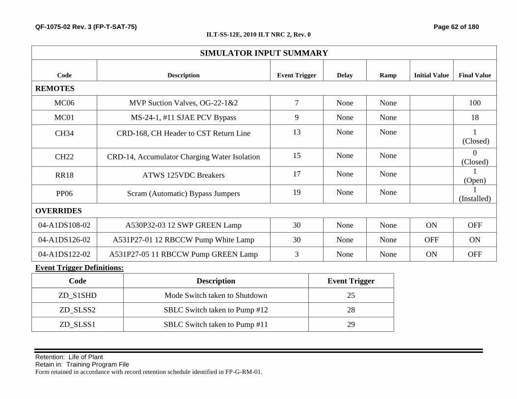
QF-1075-02 Rev. 3 (FP-T-SAT-75) Page 62 of 180 ILT-SS-12E, 2010 ILT NRC 2, Rev. 0
Retention: Life of Plant Retain in: Training Program File Form retained in accordance with record retention schedule identified in FP-G-RM-01.
SIMULATOR INPUT SUMMARY
Code Description Event Trigger Delay Ramp Initial Value Final Value
REMOTES
MC06 MVP Suction Valves, OG-22-1&2 7 None None 100
MC01 MS-24-1, #11 SJAE PCV Bypass 9 None None 18
CH34 CRD-168, CH Header to CST Return Line 13 None None 1
(Closed)
CH22 CRD-14, Accumulator Charging Water Isolation 15 None None 0
(Closed)
RR18 ATWS 125VDC Breakers 17 None None 1
(Open)
PP06 Scram (Automatic) Bypass Jumpers 19 None None 1
(Installed)
OVERRIDES
04-A1DS108-02 A530P32-03 12 SWP GREEN Lamp 30 None None ON OFF
04-A1DS126-02 A531P27-01 12 RBCCW Pump White Lamp 30 None None OFF ON
04-A1DS122-02 A531P27-05 11 RBCCW Pump GREEN Lamp 3 None None ON OFF
Event Trigger Definitions:
Code Description Event Trigger
ZD_S1SHD Mode Switch taken to Shutdown 25
ZD_SLSS2 SBLC Switch taken to Pump #12 28
ZD_SLSS1 SBLC Switch taken to Pump #11 29

QF-1075-02 Rev. 3 (FP-T-SAT-75) Page 63 of 180 ILT-SS-12E, 2010 ILT NRC 2, Rev. 0
Retention: Life of Plant Retain in: Training Program File Form retained in accordance with record retention schedule identified in FP-G-RM-01.
Manual Settings:
11. Reset to IC282.
a. If necessary, IC 282 can be recreated from IC 15 as follows:
o Defeat the Auto Start feature on 12 RBCCW Pump. (White lamp will be overridden on)
o Establish Event triggers and commands per the Simulator Input Summary.
12. Manually activate event Trigger 30 to establish the initial conditions for the scenario.
13. Tag out #12 Service Water Pump.
14. Verify Event Trigger Definitions:
a. Event Trigger 25 initiates a complete loss of Main Condenser Vacuum when the Turbine trips.
b. Event Triggers 28 and 29 remove the trip in one second from the SBLC pump that is NOT initially started. This will allow the second SBLC Pump to
start.
15. Verify the Malfunctions match the Simulator Input Summary.
16. Verify the Remotes match the Simulator Input Summary.
17. Verify the Overrides match the Simulator Input Summary.
18. Verify the following conditions:
a. A step stool is available in the back-panel area (for reaching the MSIV Low-Low Level Isolation Bypass switches).
19. Perform the applicable sections of the SIMULATOR SETUP CHECKLIST.
20. Provide the following for the operating crew :
a. A scenario specific Form 3139, Control Room Shift Turnover Checklist
b. A scenario specific Form 3140, Shift Supervision Turnover Checklist

QF-1075-02 Rev. 3 (FP-T-SAT-75) Page 64 of 180 ILT-SS-12E, 2010 ILT NRC 2, Rev. 0
Retention: Life of Plant Retain in: Training Program File Form retained in accordance with record retention schedule identified in FP-G-RM-01.
Attach the following site-specific information as necessary:
Simulator Set-up Checklist (before and after training)
Pre-evaluation Brief Guide (for evaluations only)
Post-evaluation Critique (for evaluations only)
Turnover Log
Historical Record:

QF-1075-02 Rev. 3 (FP-T-SAT-75) Page 65 of 180 ILT-SS-12E, 2010 ILT NRC 2, Rev. 0
Retention: Life of Plant Retain in: Training Program File Form retained in accordance with record retention schedule identified in FP-G-RM-01.
Simulator Scenario Development Checklist
Mark with an X Yes or No for any of the following. If the answer is No, include justification for the no
answer or the corrective action needed to correct the discrepancy after the item.
12. The scenario contains objectives for the desired tasks and relevant human performance tools. Yes No
13. The scenario identifies key parameter response, expected alarms, and automatic actions
associated with the induced perturbations.
Yes No
14. The scenario content adequately addresses the desired tasks, through simulator performance,
instructor-led training freezes, or both.
Yes No
15. Plant PRA initiating events, important equipment, and important tasks are identified. Yes No
16. Turnover information includes a Daily At Power or Shutdown Safety Risk Assessment. Yes No
17. The scenario contains procedurally driven success paths. Procedural discrepancies are
identified and corrected before training is given.
Yes No
18. The scenario guide includes responses for all anticipated communications to simulated
personnel outside the Control Room, based on procedural guidance and standard operating
practices. Include estimated completion times and/or notes for use of time compression.
Yes No
19. The scenario includes related industry experience. SOER, SER and similar OE
recommendations are clearly identified and fully addressed.*
Yes No
20. The scenario guide incorporates verification of Operator Fundamental application.* Yes No
21. Training elements and specific human performance elements are addressed in the scenario
critique guide to be used by the critique facilitator. The critique guide includes standards for
expected performance.*
Yes No
22. For evaluations, it has been verified that without operator action the critical tasks will be
failed.
Yes No
Developer and Reviewer: Once checklist is completed and deficiencies are corrected, sign the cover page.
* For evaluations these items may be marked NO without justification.

QF-1075-02 Rev. 3 (FP-T-SAT-75) Page 66 of 180 ILT-SS-12E, 2010 ILT NRC 2, Rev. 0
Retention: Life of Plant Retain in: Training Program File Form retained in accordance with record retention schedule identified in FP-G-RM-01.
Simulator Scenario Validation Checklist
Mark with an X Yes or No for any of the following. If the answer is No, include an explanation after the
item.
8. The desired initial condition(s) could be achieved.
Yes
No
9. All malfunctions and other instructor interface items were functional and responded to
support the simulator scenario.
Yes
No
10. All malfunctions and other instructor interface items were initiated in the same
sequence described within the simulator scenario.
Yes
No
11. All applicable acceptance criteria were met for procedures that were used to support
the simulator scenario.
Yes
No
12. During the simulator scenario, observed changes corresponded to expected plant
response.
Yes
No
13. Did the scenario satisfy the learning or examination objectives without any significant
simulator performance issues, or deviations from the approved scenario sequence? If
learning objective(s) could not be satisfied, identify the objectives in the Simulator
Action Request
Yes
No
14. Evaluation: The simulator is capable of being used to satisfy learning or examination
objectives without exceptions, significant performance discrepancies, or deviation
from the approved scenario sequence.
Yes
No
Discrepancies noted (Check “none” or list items found) None
SMAR = Simulator Action Request
SMAR: SMAR: SMAR: SMAR:
Comments:
Validator: Sign the cover page only after noted discrepancies are corrected or compensatory actions are taken to ensure
quality training.

Monticello NRC EXAM Scenario 3
Appendix D Scenario Outline Form ES-D-1
Facility: Monticello Scenario No.: NRC Scenario 3 Op-Test No.: MNGP 2010
Examiners: ____________________________ Operators: _____________________________ ____________________________ _____________________________ ____________________________ _____________________________
Initial Conditions: 46% Power, normal shutdown in progress 12 Core Spray Pump Out of Service
Turnover: Secure #11 RFP then continue inserting control rods for shutdown
Event No.
Malf. No. Event Type*
Event Description
1 None N
BOP
Secure #11 RFP.
2 None R
ATC/SRO
Insert control rods for shutdown.
3 CH07B I
ATC/SRO
While inserting control rods, the in-service CRD Flow Control Valve will fail, requiring a shift to the alternate FCV.
4 SL02A (TS only) SRO
(Optional) Loss of continuity to one SBLC Squib valve. (TS)
5 01-DS085-02 01-DS084-02
(TS only) SRO
(Optional) A Core Spray becomes inoperable when the Inboard Inject valve is found deenergized (TS)
6 ED06B
C
BOP/SRO
(Optional) Loss of Turbine Bldg Load Center 102 (ABN)
7 CH08A CH08B
I
ATC/SRO
11 CRD Pump trip / restore with 12 CRD Pump / 12 CRD Pump trip (ABN). Immediate Reactor Shutdown (ABN)
8 CH22A
CH22B
03-S45-04
M Crew
Loss of both CRD pumps. Manual scram for 2nd accumulator (CT) and performs EOP 1100. In-Plant personnel begin reporting indications of leak in the Scram Discharge Volume. The Scram discharge Volume high Level Trip cannot be bypassed to reset the scram. When parameters in 2 areas exceed Max Safe values, Emergency Depressurization is performed. (CT)
9 AP08D I
BOP
D ADS SRV Stuck closed
(N)ormal, (R)eactivity, (I)nstrument, (C)omponent, (M)ajor
ES-301-4 Quantitative attributes: Total Malfunctions (5-8): 7 Malfunction(s) after EOP (1-2): 2 Abnormal Events (2-4): E6 & E7 Major Transient(s) /E-Plan entry (1-2): E8 EOPs (1-2): 1300, 1100 EOP Contingencies (0-2): ED Critical Tasks (2-3): 2
ES-301-5 Quantitative attributes: BOP Normal: E1 ATC Reactivity (1 per set): E2 BOP I/C (4 / set): E6 & 9 ATC I/C (4 / set): E3 & 7 SRO-I I/C (4 / set inc 2 as ATC): E3, 6 & 7 SRO Tech Spec (2 per set): E4 & 5 ALL Major Transients (2 per set): 1

QF-1075-02 Rev. 3 (FP-T-SAT-75)
Retention: Life of Plant Retain in: Training Program File Form retained in accordance with record retention schedule identified in FP-G-RM-01.
SIMULATOR EXERCISE GUIDE (SEG)
SITE: MONTICELLO SEG # ILT-SS-13E
SEG TITLE: 2010 ILT NRC 3 REV. # 0
PROGRAM: INITIAL LICENSE TRAINING #: MT-ILT
COURSE: NRC EXAM #: M-8119
TOTAL TIME: 1.5 HOURS
Additional site-specific signatures may be added as desired.
Developed by:
Instructor Date
Reviewed by:
Instructor
(Simulator Scenario Development Checklist.)
Date
Validated by:
Validation Lead Instructor
(Simulator Scenario Validation Checklist.)
Date
Approved by:
Training Supervision Date

QF-1075-02 Rev. 3 (FP-T-SAT-75) Page 69 of 180 ILT-SS-13E, 2010 ILT NRC 3, Rev. 0
Retention: Life of Plant Retain in: Training Program File Form retained in accordance with record retention schedule identified in FP-G-RM-01.
Guide Requirements
Goal of Training:
ILT NRC Exam
Learning Objectives:
15. Demonstrate the ability to predict and/or monitor changes in
parameters associated with operating system controls for the
appropriate tasks.
16. Demonstrate the ability to correctly use procedures to correct,
control, or mitigate the consequences of normal and abnormal
operations for the appropriate tasks.
17. Demonstrate the ability to monitor automatic operations of the
systems to ensure proper operation for the appropriate tasks.
18. Demonstrate the ability to manually operate and/or monitor systems
in the control room in accordance with approved procedures for the
appropriate tasks.
19. Demonstrate the ability to complete administrative requirements, as
necessary, in order to operate the plant for the appropriate tasks.
20. Demonstrate knowledge of and ability to implement shift
supervision duties as they relate to crew operations for the
appropriate tasks.
21. Given a degrading or improving plant condition or event,
demonstrate the ability to: (CRS)
a. Evaluate trends that may result in equipment damage or reduction
in plant safety.
b. Ensure proper diagnosis of plant problems by monitoring and
interpreting data (information from panel indications).
c. Evaluate and diagnose challenges to Critical Plant Parameters.
d. Evaluate events and accidents.
Prerequisites: 3. Completion of MT-ILT Training Program
Training Resources:
15. Full Scope Simulator
16. 3139 (Control Room Shift Turnover Checklist)
17. 3140 (Shift Supervisors Office Shift Turnover Checklist)
18. Simulator Driver
19. Simulator Phone Talker
20. Operations Representative
21. Evaluators
References: 49. B.01.03-05 (CRD HYDRAULIC SYSTEM)
50. B.02.04-05 (MAIN STEAM)
51. B.05.05-05 (RMCS)
52. B.06.06-05 (CONDENSATE AND REACTOR FEEDWATER)

QF-1075-02 Rev. 3 (FP-T-SAT-75) Page 70 of 180 ILT-SS-13E, 2010 ILT NRC 3, Rev. 0
Retention: Life of Plant Retain in: Training Program File Form retained in accordance with record retention schedule identified in FP-G-RM-01.
53. C.3 (SHUTDOWN PROCEDURES)
54. C.4-B.01.03.A (LOSS OF CRD PUMP FLOW)
55. C.4-B.06.03.A (DECREASING CONDENSER VACUUM)
56. C.4-B.06.04.A (DECREASED CIRCULATING WATER FLOW)
57. C.4-B.09.07-B (480 VOLT STATION AUXILIARY)
58. C.4-A (REACTOR SCRAM)
59. C.4-K (IMMEDIATE REACTOR SHUTDOWN)
60. C.5-1100 (RPV CONTROL)
61. C.5-1300 SECONDARY CONTAINMENT CONTROL)
62. C.5-2002 (EMERGENCY RPV DEPRESSURIZATION)
63. C.6-003-B-56 (HIGH AREA TEMP STEAM LEAK)
64. C.6-004-A-11 (REACTOR BUILDING HI RADIATION)
65. C.6-005-B-17 (CHARGING WATER LO PRESSURE)
66. C.6-005-B-25 (33) CRD PUMP 3-16A(B) BREAKER TRIPPED
67. C.6-005-B-26 (34) CRD PUMP 3-16A(B) OL
68. C.6-005-B-31 (LOSS OF CONTINUITY TO SQUIB VALVE)
69. C.6-008-C-30 (NO. 102 TRANS 480V BKR TRIP)
70. C.6-00 8-C-5 (NO. 1R RES TRANS TROUBLE)
71. Tech Specs Section 3.1
72. Tech Specs Section 3.5
Commitments: 3. None
Evaluation Method:
ILT NRC Exam
Operating Experience:
Not Applicable / ILT Exam

QF-1075-02 Rev. 3 (FP-T-SAT-75) Page 71 of 180 ILT-SS-13E, 2010 ILT NRC 3, Rev. 0
Retention: Life of Plant Retain in: Training Program File Form retained in accordance with record retention schedule identified in FP-G-RM-01.
Related PRA Information:
Initiating Event with Core Damage Frequency Contribution:
Internal Flood (36.8%)
Station Blackout (27.4%)
Loss of High Pressure Injection (13.4%)
ATWS (11.4%)
LOCA (7.7%)
Loss of Low Pressure Injection (2.0%)
LOCA Outside Containment (0.6%)
Loss of Containment Heat Removal (0.4%)
Important Components:
EDGs
HPCI
RCIC
Scram
Feed/Cond
SRV (When stuck open)
SRVs
Instrument AC
Fire System (for RPV Injection)
4160 VAC
Important Operator Actions with Task Number:
CR314.101, Emergency Depressurize
CR305.108, Recover Offsite Power
CR305.105/6, SBO-Recover an EDG
CR305.121, Align #13 EDG to Essential MCCs
CR314.126, Vent Containment
CR259.127, Control Feedwater following a Scram
CR314.112, Control Reactor Water Level during an ATWS
CR211.106, Inject with SBLC during an ATWS

QF-1075-02 Rev. 3 (FP-T-SAT-75) Page 72 of 180 ILT-SS-13E, 2010 ILT NRC 3, Rev. 0
Retention: Life of Plant Retain in: Training Program File Form retained in accordance with record retention schedule identified in FP-G-RM-01.
TASKS ASSOCIATED WITH SIMULATOR EXERCISE(S):
Shift Manager Tasks:
None
SRO Tasks:
SS200.142 Direct Reactor Shutdown IAW C.3 6, 7
SS211.000 Standby Liquid Control Duty Area 6, 7
SS299.349 Apply administrative requirements for Tech Spec
Section 3.1 and Bases to Reactivity Control Systems
6, 7
SS299.353 Apply administrative requirements for Tech Spec
Section 3.5 and Bases to ECCS and RCIC
6, 7
SS304.193 Implement RPV control 6, 7
SS314.196 Implement Secondary Containment control 6, 7
SS314.198 Implement Emergency RPV Depressurization 6, 7
SS315.101 Supervise response to a reactor scram 6, 7
SS315.102 Supervise response to loss of CRD Pump flow 6, 7
SS315.127 Supervise the response to decreasing condenser
vacuum
6, 7
SS315.129 Supervise the response to decreased Circulating
Water flow
6, 7
SS315.142 Supervise the response to loss of power to LC-102 or
its MCCs
6, 7
SS315.164 Supervise immediate reactor shutdown 6, 7

QF-1075-02 Rev. 3 (FP-T-SAT-75) Page 73 of 180 ILT-SS-13E, 2010 ILT NRC 3, Rev. 0
Retention: Life of Plant Retain in: Training Program File Form retained in accordance with record retention schedule identified in FP-G-RM-01.
RO Tasks:
CR200.135 Perform a power reduction to 25% 1-5
CR200.146 Perform the procedure for Rx Scram 1-5
CR200.147 Perform the procedure for loss of CRD Pump Flow 1-5
CR200.172 Perform the procedure for decreasing condenser
vacuum
1-5
CR200.174 Perform the procedure decreased Circulating Water
flow
1-5
CR200.186 Perform the procedure for loss of power to LC-102 or
its MCCs
1-5
CR200.208 Perform the procedure for immediate reactor
shutdown
1-5
CR201.111 Place the standby CRD Flow Control Valve in
service
1-5
CR201.138 Operate RMCS during Control Rod Movement 1-5
CR203.113 Place Torus Cooling in service during abnormal and
emergency conditions
1-5
CR211.000 Standby Liquid Control 1-5
CR256.118 Shutdown the Condensate and Reactor Feedwater
system
1-5
CR259.127 Control Feedwater following a Scram 1-5
CR304.102 Perform actions associated with RPV control 1-5
CR304.105 Perform actions associated with Secondary
Containment Control
1-5
CR314.101 Perform actions associated with Emergency
Depressurization
1-5
STA Tasks:
None

QF-1075-02 Rev. 3 (FP-T-SAT-75) Page 74 of 180 ILT-SS-13E, 2010 ILT NRC 3, Rev. 0
Retention: Life of Plant Retain in: Training Program File Form retained in accordance with record retention schedule identified in FP-G-RM-01.
QUANTITATIVE ATTRIBUTES (Use this form for Evaluations only.)
Malfunctions:
Before EOP Entry:
9. CRD Flow control Valve failure
10. (Optional) Loss of LC-102 (TS)
11. (Optional) Loss of SBLC Squib Valve Continuity (TS)
12. Loss of CRD Pumps
13. (Optional) A Core Spray Inoperability
After EOP Entry:
5. Scram reset switch failure
6. 1 ADS SRV fails to open
Abnormal Events:
9. Loss of LC-102
10. Loss of CRD
11. Immediate Reactor Shutdown
Major Transients:
3. Unisolable Scram Discharge Volume leak
Critical Tasks:
6. CT-1: Within 5 minutes of the second accumulator low pressure alarm, scram the reactor when no CRD pump is
running and the second accumulator low pressure alarm is received.
7. CT-34: When a primary system is discharging into the secondary containment through an unisolable break,
perform an Emergency Depressurization per C.5-2002 when max safe operating values are exceeded in two or
more areas.

QF-1075-02 Rev. 3 (FP-T-SAT-75) Page 75 of 180 ILT-SS-13E, 2010 ILT NRC 3, Rev. 0
Retention: Life of Plant Retain in: Training Program File Form retained in accordance with record retention schedule identified in FP-G-RM-01.
SCENARIO OVERVIEW:
INITIAL CONDITIONS:
8. IC 283, 46 %Power, Shutdown in progress
9. The initial plant conditions are:
Normal Shutdown is in progress
10. The following equipment is OOS
12 Core Spray Pump
11. The following evolutions are planned for the shift:
Continue the shutdown in accordance with C.3
Secure the 11 Feed Pump
Continue control rod insertion
SEQUENCE OF EVENTS:
Event 1: Secure the 11 RFP.
The BOP coordinates with the Out Plant Operator to secure the 11 Reactor Feed Pump.
Event 2: Insert control rods for shutdown.
Control Rods are inserted using the recommendations provided by the Nuclear Engineer.
Event 3: The in-service CRD Flow Control Valve will fail
While inserting control rods, the in-service CRD Flow Control Valve will fail, requiring a shift to the
alternate FCV.
Event 4: (OPTIONAL) Loss of continuity to one SBLC Squib valve.
Loss of electrical continuity on “A” SBLC Squib valve will occur which will require the CRS to
declare “A” SBLC system INOPERABLE. Crew will evaluate Tech Specs and determine LCO
3.1.7 is NOT MET with Condition B applicable.

QF-1075-02 Rev. 3 (FP-T-SAT-75) Page 76 of 180 ILT-SS-13E, 2010 ILT NRC 3, Rev. 0
Retention: Life of Plant Retain in: Training Program File Form retained in accordance with record retention schedule identified in FP-G-RM-01.
Event 5: (OPTIONAL) A Core Spray Inoperability
The Reactor Bldg Operator finds the breaker tripped at MCC133 for MO-1753, A Core Spray
Injection Inboard. With both Core Spray systems now inoperable, Tech Spec 3.5.1 Condition F is
entered.
Event 6: (OPTIONAL) Loss of Turbine Bldg Load Center 102
Loss of LC-102 results in the loss of: #12 Circ Water Pump, #12 Steam Packing Exhauster, #12
Stator Cooling Pump, cooling fans for the 1R Transformer, and #12 EDG control panel C-94. The
BOP secures the electric plant lineup and takes appropriate actions for the affected systems. The
plant will continue to operate without immediate challenge.
Event 7: Loss of CRD Pump 11, Start CRD Pump 12, Loss of CRD Pump 12
11 CRD Pump trips and cannot be restarted. The 12 CRD Pump can be started and CRD parameters
stabilized. However, one minute later, the 12 CRD pump will also trip.
With no CRD flow, the abnormal procedure is performed, which requires an immediate reactor
shutdown when the second CRD accumulator low pressure alarms.
Event 8: Unisolable Scram Discharge Volume Rupture
Following the manual scram, the Scram Discharge Volume vents and drains fail to close. The leak
cannot be isolated and the Scram cannot be reset.
Turbine Bypass valves can be used to lower RPV pressure in anticipation of Emergency
Depressurization.
When parameters in 2 areas exceed Max Safe values, Emergency Depressurization is performed.
Event 9: Only 2 of 3 ADS valves will open
When Emergency Depressurization is performed the D ADS SRV fails to open. The BOP must
open an additional SRV to establish a total of 3 SRVs open.

QF-1075-02 Rev. 3 (FP-T-SAT-75) Page 77 of 180 ILT-SS-13E, 2010 ILT NRC 3, Rev. 0
Retention: Life of Plant Retain in: Training Program File Form retained in accordance with record retention schedule identified in FP-G-RM-01.
NOTE: Table may be modified as needed to include all scenario time-line items
SCENARIO TIME-LINE:
SEQ SEQUENCE OF EVENTS / INSTRUCTOR NOTES CREW
POS EXPECTED STUDENT RESPONSES
37. INITIAL CONDITIONS (IC):
v. IC: 283
w. Mode: 1, Shutting down
x. Power: 46 %
y. Generator: 249 Mwe
z. Recirc Flow is 35.7 mlb/Hr
aa. Xcel system condition is GREEN
bb. Plant CDF is YELLOW
cc. River temp is 56°F and NO towers are in service
dd. Outside temp is 60°F
ee. 12 Core Spray Pump is out of service
ff. 12 Steam Packing Exhauster is in service
gg. The next evolution is shutdown of the 11 RFP.
hh. Ensure C.3 (Shutdown) is marked to Step IV.C.2
38. SIMULATOR SET UP
k. Set the plant initial conditions per the Initial conditions under the Scenario Overview, Initial Conditions, and Manual Settings.
l. Enter the malfunctions, remotes, overrides and event triggers per the “Simulator Input Summary”.
m. Control Room and Shift Supervisor turnover checklists should be provided with the scenario IC.
n. Core Damage Frequency (CDF) should be updated on the status board.

QF-1075-02 Rev. 3 (FP-T-SAT-75) Page 78 of 180 ILT-SS-13E, 2010 ILT NRC 3, Rev. 0
Retention: Life of Plant Retain in: Training Program File Form retained in accordance with record retention schedule identified in FP-G-RM-01.
SCENARIO TIME-LINE:
SEQ SEQUENCE OF EVENTS / INSTRUCTOR NOTES CREW
POS EXPECTED STUDENT RESPONSES
o. Tech Spec Required Actions should be updated on the status board.
39. COMPLETE TURNOVER:
a. Review applicable current Unit Status
b. Review relevant At-Power Risk status
c. Review current LCOs not met and Action Requirements
B Core Spray Pump, Condition B, Day 1 of 7, breaker removed for
maintenance.
d. Verify crew performs walk down of control boards and reviews turnover checklists.
e. Plant Staffing The following support is available:
Normal Weekday Night Shift
Operations: Normal crew compliment based on actual crew staffing for shutdown.
Maintenance: Available as needed or requested.
Engineering: Available as needed or requested.
Management: Available as needed or requested.
f. Shift Activities
1) Continue the shutdown, holding at Step C.3 IV.C.2
2) Stop the 11 Reactor Feed Pump, leave it in a warmup lineup
3) Continue with control rod insertion per the Nuclear Engineer’s recommendations

QF-1075-02 Rev. 3 (FP-T-SAT-75) Page 79 of 180 ILT-SS-13E, 2010 ILT NRC 3, Rev. 0
Retention: Life of Plant Retain in: Training Program File Form retained in accordance with record retention schedule identified in FP-G-RM-01.
SCENARIO TIME-LINE:
SEQ SEQUENCE OF EVENTS / INSTRUCTOR NOTES CREW
POS EXPECTED STUDENT RESPONSES
40. SHIFT BRIEF
a. Role Play as necessary. Turbine Building status: CRS Leads the Shift Brief
14). Hydrogen Water Chemistry System has been secured
ATC/BOP Participate in Shift Brief
15). A, B, & C Condensate demins in service. ATC/BOP Participate in Shift Brief
16). C highest @ 5 psid.
17). Assigned to support the shutdown of 11 RFP after turnover.
18). #12 Steam Packing Exhauster is in service
19). All systems in Turbine building are normal.
b. Role Play as necessary. Rx Building status:
20). No Maintenance is in progress
21). All other systems in the Rx bldg are normal.
c. Role Play as necessary. Third Operator:
22). Nothing to add CRS Crew assumes the duty.

QF-1075-02 Rev. 3 (FP-T-SAT-75) Page 80 of 180 ILT-SS-13E, 2010 ILT NRC 3, Rev. 0
Retention: Life of Plant Retain in: Training Program File Form retained in accordance with record retention schedule identified in FP-G-RM-01.
SCENARIO TIME-LINE:
SEQ SEQUENCE OF EVENTS / INSTRUCTOR NOTES CREW
POS EXPECTED STUDENT RESPONSES
Event 1 41. Secure 11 RFP.
a. Role Play the Plant Equipment Operator at the 11 RFP as necessary to support the shutdown
CRS Directs the BOP to secure the 11 RFP IAW C.3.C Step 2 and B.06.05
BOP Starts 11 RFP Aux Oil Pump and verifies that it is running
Establishes communications with the Plant Equipment
Operator to monitor FIS-3489
Assures that suction flow does not drop below 1200 gpm
b. Role play Turbine Bldg operator as necessary and close FW-68-1 using MANUAL TRIGGER 1
Slowly closes FW-68-1 RFP Discharge valve, allowing FIC-
3489 time to open the Recirc Valve
1) Verify Remote Function FW46 modifies to 0 (Closed) over 30 seconds
Verify that CV-3489, 11 RFP P-2A FW Recirc to Condenser,
OPENS and controls flow at approximately 3300 gpm
Stop 11 RFP
Verify that CV-3489, 11 RFP P-2A FW Recirc to Condenser,
CLOSES approximately 11 seconds after the pump trip
c. Role play Turbine Bldg operator as necessary. If directed, re-open FW-68-1 using MANUAL TRIGGER 3
Re-open FW-68-1 RFP Discharge valve while monitoring
Pump Discharge Pressure (PI-1130) and Feed Reg Valve
position
1) Verify Remote Function FW46 modifies to 100 (Open) over 30 seconds
Directs the Plant equipment Operator to open the Warm-up
valves for 11 RFP (FW-69-1 & FW-70-1)
d. Role play Turbine Bldg operator as necessary if asked for #12 RFP Running Amps. Report #12 RFP running at 685amps
Event 2 42. Insert control rods for shutdown.
CRS Directs OATC to continue lowering reactor power by inserting control
rods as recommended by the Nuclear Engineer
Perform a reactivity manipulation Brief

QF-1075-02 Rev. 3 (FP-T-SAT-75) Page 81 of 180 ILT-SS-13E, 2010 ILT NRC 3, Rev. 0
Retention: Life of Plant Retain in: Training Program File Form retained in accordance with record retention schedule identified in FP-G-RM-01.
SCENARIO TIME-LINE:
SEQ SEQUENCE OF EVENTS / INSTRUCTOR NOTES CREW
POS EXPECTED STUDENT RESPONSES
Checks the relationship to Unacceptable region of the Reactor Power
Validation Curve
ATC Lowers power by inserting control rods using the A2SD sequence,
Step 10 (Backwards) For each rod:
Selects desired control rod (18-43, 42-35, 10-19)
a. After the first rod is inserted and as directed by the Lead Examiner, insert MANUAL TRIGGER 5 to begin Event 3
Takes the ROD MOVEMENT CONTROL switch to ROD IN
and holds until rod is at position 00
1. Verify the following MALFUNCTION goes active: CH07B, CRD Flow control Valve fails closed
Monitors the following:
o APRMs
Relationship to Gardel thermal power
within 2%
o Core Flow
o Recirculation flow
o Steam flow
o Feedwater flow
o RPV Water level
Event 3 43. The in-service CRD Flow Control Valve fails
Key Parameter Response: Reduced CRD cooling water flow, inability
to drive control rods
Key Expected Alarm: 5-B-41, CRD HI TEMPERATURE (Possible)
Auto Actions: CRD Flow Control valve is closed.
ATC Responds to annunciator

QF-1075-02 Rev. 3 (FP-T-SAT-75) Page 82 of 180 ILT-SS-13E, 2010 ILT NRC 3, Rev. 0
Retention: Life of Plant Retain in: Training Program File Form retained in accordance with record retention schedule identified in FP-G-RM-01.
SCENARIO TIME-LINE:
SEQ SEQUENCE OF EVENTS / INSTRUCTOR NOTES CREW
POS EXPECTED STUDENT RESPONSES
Informs Shift Supervision
a. If directed to investigate CRD temperatures, wait 2 minutes and report that many CRD temperatures are rising and that CRD 26-15 is in alarm. The highest reading temperature is 255°F.
o Sends Reactor Building Operator to investigate CRD
temperature recorder
o Refers to procedure B.01.03-05 CRDH
o Recognizes CRD FCV failure
CRS Directs swap to standby CRD FCV
b. When directed to report to the CRD FCV station to support shift of FCV, WAIT 3 minutes and report you are standing by.
ATC Coordinates with Reactor Building Operator and performs the
following:
o Opens standby FCV manual inlet/outlet valves
o Places Flow Controller in MANUAL
o Manually runs controller to 0

QF-1075-02 Rev. 3 (FP-T-SAT-75) Page 83 of 180 ILT-SS-13E, 2010 ILT NRC 3, Rev. 0
Retention: Life of Plant Retain in: Training Program File Form retained in accordance with record retention schedule identified in FP-G-RM-01.
SCENARIO TIME-LINE:
SEQ SEQUENCE OF EVENTS / INSTRUCTOR NOTES CREW
POS EXPECTED STUDENT RESPONSES
Event 3 Continued
ATC Places the CRD Flow Selector to the B position
c. When directed to OPEN CRD-16-2 and CRD-18-2, WAIT 2 minutes, then use MANUAL TRIGGER 7 to modify REMOTE FUNCTION CH17 to OPEN and report this action to the Control room.
Slowly OPENS the B FCV manually to approximately 54 to
56 gpm
Places the FCV in AUTO
d. When directed to CLOSE CRD-16-1 and CRD-18-1, WAIT 2 minutes, then use MANUAL TRIGGER 9 to modify REMOTE FUNCTION CH16 to CLOSE and report this action to the Control room
Closes previously in-service FCV manual inlet/outlet valves
Acknowledge annunciator 5-B-41 clear and informs Shift
Supervision.
e. If directed to report CRD temperatures, report all alarms are clear and all temperatures are lowering to normal.
Places the CRD Flow Selector to the B position
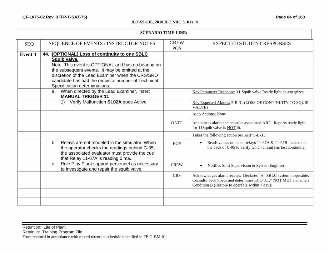
QF-1075-02 Rev. 3 (FP-T-SAT-75) Page 84 of 180 ILT-SS-13E, 2010 ILT NRC 3, Rev. 0
Retention: Life of Plant Retain in: Training Program File Form retained in accordance with record retention schedule identified in FP-G-RM-01.
SCENARIO TIME-LINE:
SEQ SEQUENCE OF EVENTS / INSTRUCTOR NOTES CREW
POS EXPECTED STUDENT RESPONSES
Event 4 44. (OPTIONAL) Loss of continuity to one SBLC Squib valve.
Note: This event is OPTIONAL and has no bearing on the subsequent events. It may be omitted at the discretion of the Lead Examiner when the CRS/SRO candidate has had the requisite number of Technical Specification determinations.
a. When directed by the Lead Examiner, insert MANUAL TRIGGER 11
Key Parameter Response: 11 Squib valve Ready light de-energizes
1) Verify Malfunction SL02A goes Active Key Expected Alarms: 5-B-31 (LOSS OF CONTINUITY TO SQUIB
VALVE)
Auto Actions: None
OATC Announces alarm and consults associated ARP. Reports ready light
for 11Squib valve is NOT lit.
Takes the following action per ARP 5-B-31:
b. Relays are not modeled in the simulator. When the operator checks the readings behind C-05, the associated evaluator must provide the cue that Relay 11-67A is reading 0 ma.
BOP Reads values on meter relays 11-67A & 11-67B located on
the back of C-05 to verify which circuit has lost continuity.
c. Role Play Plant support personnel as necessary to investigate and repair the squib valve.
CREW Notifies Shift Supervision & System Engineer.
CRS Acknowledges alarm receipt. Declares “A” SBLC system inoperable.
Consults Tech Specs and determines LCO 3.1.7 NOT MET and enters
Condition B (Restore to operable within 7 days).

QF-1075-02 Rev. 3 (FP-T-SAT-75) Page 85 of 180 ILT-SS-13E, 2010 ILT NRC 3, Rev. 0
Retention: Life of Plant Retain in: Training Program File Form retained in accordance with record retention schedule identified in FP-G-RM-01.
SCENARIO TIME-LINE:
SEQ SEQUENCE OF EVENTS / INSTRUCTOR NOTES CREW
POS EXPECTED STUDENT RESPONSES
Event 5 45. (OPTIONAL) A Core Spray Inoperability
Note: This event is OPTIONAL and has no bearing on the subsequent events. It may be omitted at the discretion of the Lead Examiner when the CRS candidate has had the requisite number of TS Calls.
a. When directed by the Lead Examiner, insert MANUAL TRIGGER 13
Key Parameter Response: A report from the Reactor Bldg. will be
necessary. Both red and green indicating lights for MO-1753 on C-03
will be off.
1) Verify Overrides 01-DS085-02 and 01-DS084-02 go active.
Key Expected Alarms: None
b. Role Play Reactor Bldg operator. Report that you were investigating an acrid odor and found Breaker 3324 on MCC-133 is in the trip free position
Auto Actions: None
BOP Identifies that MO-1753 appears deenergized
2) If an attempt to reset the breaker is made, it will not reset
CRS Evaluate Tech Spec Section 3.5
Identify that A Core Spray is inoperable.
Enter TS 3.5.1 Condition F, 72 Hour Action statement
Event 6 46. (OPTIONAL) Loss of Turbine Bldg Load Center 102

QF-1075-02 Rev. 3 (FP-T-SAT-75) Page 86 of 180 ILT-SS-13E, 2010 ILT NRC 3, Rev. 0
Retention: Life of Plant Retain in: Training Program File Form retained in accordance with record retention schedule identified in FP-G-RM-01.
SCENARIO TIME-LINE:
SEQ SEQUENCE OF EVENTS / INSTRUCTOR NOTES CREW
POS EXPECTED STUDENT RESPONSES
Note: This event is OPTIONAL and has no bearing on the subsequent events. It may be omitted at the discretion of the Lead Examiner when the BOP candidate has had the requisite number of Instrument/Component failures.
Key Parameter Response: Breaker 57-201 OPEN and 0 amps
indicated on LC-102.
Key Expected Alarms: 8-C-30 (No. 102 Trans 480v Bkr Trip) and 8-
C-5 (No. 1R Res Trans Trouble)
a. When directed by the Lead Examiner, insert MANUAL TRIGGER 15
Auto Actions: Loss of #12 Circ Water Pump, #12 Steam Packing
Exhauster, #12 Stator Cooling Pump, cooling fans for the 1R
Transformer, and #12 EDG control panel C-94
1) Verify Malfunction ED06A goes active BOP Responds to annunciator 8-C-30, NO. 102 TRANS 480V BKR TRIP,
and informs the CRS
b. Role Play the dispatched operator as necessary. Report that ½ of the cooling fans are off
BOP May respond to C-08-C-5, NO. 1R RES TRANS TROUBLE)
by dispatching an operator to investigate (from a distance)
the 1R Trouble alarm
Performs actions of C.4-B.09.07.B (Loss of Power To LC-102 or its
MCCs).
c. If dispatched to investigate the trip of breaker 52-201, report no apparent cause of the failure.
May dispatch an operator to investigate why breaker 52-201
tripped
BOP Verifies that Main Condenser Vacuum is stable and that no
actions are necessary per C.4-B.06.03.A (Decreasing
Condenser Vacuum)
Execute C.4-B.06.04.A (Decreased Circulating Water Flow)
Take the control switch for #12 Circ Water Pump to
SHUTDOWN and verify system valves automatically
reposition.
d. Role Play Shift Chemist as necessary to acknowledge the directive from the control room
BOP Notify the Shift Chemist to reduce the feed rate of both the
Sodium Hypochlorite and Sodium Bromide injections
systems, and any other chemical injection equipment
For loss of power to MCC-121, refer to B.09.02-5, Less than Full
Cooling for Generator Transformer.

QF-1075-02 Rev. 3 (FP-T-SAT-75) Page 87 of 180 ILT-SS-13E, 2010 ILT NRC 3, Rev. 0
Retention: Life of Plant Retain in: Training Program File Form retained in accordance with record retention schedule identified in FP-G-RM-01.
SCENARIO TIME-LINE:
SEQ SEQUENCE OF EVENTS / INSTRUCTOR NOTES CREW
POS EXPECTED STUDENT RESPONSES
Verifies Generator Load <531 MVA (13.94 K Amps) for the
loss of 6 pumps and 18 fans on MCC121.
e. Role Play Turbine Bldg Operator as necessary: The A Isophase Bus fan is running in AUTO
Dispatch an operator to verify that the A Isophase Bus cooler
is in service.
BOP Take appropriate action for Steam Packing exhauster
Starts #11 Packing Exhauster Blower
f. When the Packing Exhauster is restored, start the next event.
Opens the #11 Packing Exhauster Discharge Valve
BOP May take action for Service Water (either action)
Opens #13 SW Breaker and Starts #12 Service Water Pump
(in either order)
g. Role Play Turbine Bldg/Reactor Bldg Operators as necessary when dispatched to monitor Service water loads
Dispatch the TBO or RBO to monitor Service Water Loads
and adjust as necessary
CRS Direct response to loss of LC-102
Prioritize actions of C.4-B.09.07.B (Loss of Power to LC-102 or its
MCCs).
NOTE: It is not intended for the CRS to make this TS CALL.
Refers to TS for loss of power to #12 EDG control panel, C-94 and
enters 3.8.1 Condition B for one inoperable EDG
Event 7 47. Loss of CRD Flow / Manual Scram Actions
a. When directed by the Lead Examiner, insert MANUAL TRIGGER 17
Key Parameter Response: Indicating lights for CRD Pumps 11 & 12;
CRD Drive pressure lost
b. Verify Malfunction CH08A goes active. Key Expected Alarms: C05-B-17 (CHARGING WATER LO
PRESSURE); C05-B-25 (33) CRD PUMP 3-16A(B) BREAKER
TRIPPED; C05-B-26 (34) CRD PUMP 3-16A(B) OL
Auto Actions: None

QF-1075-02 Rev. 3 (FP-T-SAT-75) Page 88 of 180 ILT-SS-13E, 2010 ILT NRC 3, Rev. 0
Retention: Life of Plant Retain in: Training Program File Form retained in accordance with record retention schedule identified in FP-G-RM-01.
SCENARIO TIME-LINE:
SEQ SEQUENCE OF EVENTS / INSTRUCTOR NOTES CREW
POS EXPECTED STUDENT RESPONSES
ATC Respond to annunciators and notify the CRS
Verify a CRD Pump is running / Start 12 CRD Pump
Reset annunciators
Monitor and control system pressures and flows
c. Role Play Turbine Bldg/Reactor Bldg Operators as necessary when dispatched to investigate the loss of CRD. Report no apparent cause.
Investigate the reason for the loss of the 11 CRD Pump
Note: 12 CRD Pump will trip in one minute after it was started, using Event Trigger 26 to activate Malfunction CH08B
Respond to annunciators and notify the CRS
Identify that no CRD Pumps are running or can be started
Note: The second accumulator will alarm in approximately 3.5 minutes.
ATC
CRS
When the second accumulator low pressure alarm is received,
manually scram the reactor
CT-1 Within 5 minutes of the second accumulator low pressure alarm, scram the reactor when no CRD pump is running and the second accumulator low pressure alarm is received.
ATC Depresses MANUAL REACTOR SCRAM pushbuttons.
Event 8 48. Reactor Scram response (ATC): ATC Actions per C.4-A (Reactor Scram):
Place Mode Switch in SHUTDOWN.
Verify all Control Rods are inserted to or beyond position
04.
Provides scram script to CRS Reports when Reactor level
drops to less than 9” EOP entry condition.
Controls Reactor water level between +9 and +48 inches.
When reactor water level starts to increase:

QF-1075-02 Rev. 3 (FP-T-SAT-75) Page 89 of 180 ILT-SS-13E, 2010 ILT NRC 3, Rev. 0
Retention: Life of Plant Retain in: Training Program File Form retained in accordance with record retention schedule identified in FP-G-RM-01.
SCENARIO TIME-LINE:
SEQ SEQUENCE OF EVENTS / INSTRUCTOR NOTES CREW
POS EXPECTED STUDENT RESPONSES
o Place CV-6-13 Manual Loading Station Low Flow
Valve in AUTO set between 15 and 20 inches
o Close both Main FW Reg Valves
o Close MO-1133 and MO-1134 (HP Feedwater Line
Block valves
o Verify CV-6-13 is closed when RPV level reaches
+15 to +20 inches
Monitor Reactor Power
o Insert SRM and IRM detectors.
o Switch recorders from APRM to IRM.
o Range down on IRMs as necessary.
ATC Reports to CRS that SDV Vent and Drain Valves are NOT
closed.
Event 8 49. Reactor Scram response (BOP): BOP Starts performance of Part B of C.4.A
Announce over the plant paging system that a Reactor Scram
has occurred.
Open Main Generator output breakers 8N4 & 8N5.
Trip the Main Turbine.
Verify the Generator Field Breaker Open.
Start the Turbine Aux Oil Pump.
Verify Turbine Exhaust Hood Sprays in service.
Verify Main Steam Pressure Control or Low-Low Set is
controlling Reactor Pressure.

QF-1075-02 Rev. 3 (FP-T-SAT-75) Page 90 of 180 ILT-SS-13E, 2010 ILT NRC 3, Rev. 0
Retention: Life of Plant Retain in: Training Program File Form retained in accordance with record retention schedule identified in FP-G-RM-01.
SCENARIO TIME-LINE:
SEQ SEQUENCE OF EVENTS / INSTRUCTOR NOTES CREW
POS EXPECTED STUDENT RESPONSES
Event 8 50. Unisolable Scram Discharge Volume Rupture
NOTE: The malfunctions for SDV vent and drain valve failures, CH22A and CH22B, are inserted during the initial setup.
Key Parameter Response: Scram Discharge Volume Vents and Drains
remain open
Key Expected Alarms: 3-B-56 (High Area Temp Steam Leak), 4-A-11
(Reactor Building Hi Radiation)
Auto Actions: None
NOTE: It takes approximately 4 minutes for area A-11, West CRD HCU, to reach Max Safe Rad levels (1R/hr). It takes an additional 4 minutes for the second area, A-15 Reactor Bldg Drain Tank, to reach Max Safe (1R/hr).
The BOP will respond to annunciators and report to the CRS
EOP 1300 Entry Conditions
o 3-B-56 (High Area Temp Steam Leak)
o 4-A-11 (Reactor Building Hi Radiation)
CREW Perform the actions of EOP-1300 (Secondary Containment Control)
Directs evacuation of area or entire reactor building.

QF-1075-02 Rev. 3 (FP-T-SAT-75) Page 91 of 180 ILT-SS-13E, 2010 ILT NRC 3, Rev. 0
Retention: Life of Plant Retain in: Training Program File Form retained in accordance with record retention schedule identified in FP-G-RM-01.
SCENARIO TIME-LINE:
SEQ SEQUENCE OF EVENTS / INSTRUCTOR NOTES CREW
POS EXPECTED STUDENT RESPONSES
Reports Reactor Building radiation levels and temperatures
are rising
Keeps the CRS informed of Secondary Containment
parameter values and trends
ATC Attempts to manually close SDV isolation valves
BOP If directed to anticipate Blowdown, takes the Turbine PRO to
OPEN
Event 8 Continued
Unisolable Scram Discharge Volume Rupture CRS Enters EOP-1300 (Secondary Containment Control)
Direct isolation of the SDV
CRS Monitors Secondary Containment parameters
CRS May anticipate Blowdown per a C.5-1100 Override
Statement and direct RPV pressure be lowered using the
Turbine Bypass Valves
CT-34 When a primary system is discharging into the secondary containment through an unisolable break, perform an Emergency Depressurization per C.5-2002 when max safe operating values are exceeded in two or more areas.
CREW Recognizes when 2 area radiation levels have exceeded Max
Safe
CRS Enters and directs EOP-2002 (Blowdown)
Verifies Torus level > -5.9 ft.
Directs that 3 ADS SRVs be opened
BOP Perform Emergency Depressurization

QF-1075-02 Rev. 3 (FP-T-SAT-75) Page 92 of 180 ILT-SS-13E, 2010 ILT NRC 3, Rev. 0
Retention: Life of Plant Retain in: Training Program File Form retained in accordance with record retention schedule identified in FP-G-RM-01.
SCENARIO TIME-LINE:
SEQ SEQUENCE OF EVENTS / INSTRUCTOR NOTES CREW
POS EXPECTED STUDENT RESPONSES
Event 9 51. Emergency Depressurization BOP When directed by CRS, take 3 ADS SRVs to OPEN
Monitor RPV Pressure and Level
When directed by CRS, take 3 ADS SRVs to OPEN
Recognize that SRV D did NOT open
Informs the CRS of the failure
Opens a non-ADS SRV to establish 3 SRVs open.
52. SCENARIO TERMINATION
a. The scenario may be terminated when the conditions are stabilized as follows:
1) Emergency depressurization has begun
2) RPV level is stable
b. The scenario may be also terminated at the discretion of lead instructor/evaluator
Crew: Remain in simulator for potential questions from evaluator.
c. End the scenario by placing the simulator in FREEZE.
Crew: No discussion of scenario or erasing of procedure marking is allowed.

QF-1075-02 Rev. 3 (FP-T-SAT-75) Page 93 of 180 ILT-SS-13E, 2010 ILT NRC 3, Rev. 0
Retention: Life of Plant Retain in: Training Program File Form retained in accordance with record retention schedule identified in FP-G-RM-01.
SIMULATOR INPUT SUMMARY
Code Description
Event
Trigger Delay Ramp Initial Value Final Value
MALFUNCTIONS (Allow Tracking Off)
CH07B CRD FCV CV-19A Fails closed 5 None None 1 (True)
SL02A Loss of Squib “A” Continuity 11 None None 1 (True)
ED06B 480 V Load Center 102 Trip 15 None None 1 (True)
CH08A 11 CRD Pump Trip 17 None None 1 (True)
CH08B 12 CRD Pump Trip 26 00:01:00 None 1 (True)
CH22A SDV Vent Valves Fail in Open Position 30 None None 1 (True)
CH22B SDV Drain Valves Fail in Open Position 30 None None 1 (True)
AP08D SRV RV2-71-D stuck in Closed position 30 None None 1 (True)
REMOTES
CH17 “B” Flow Control Station CRD 16-2 & 18-2 7 None None 1 (Open)
CH16 “A” Flow Control Station CRD 16-1 & 18-1 9 None None 0 (Closed)
FW07 Condensate Demin D 30 None None 0 (Out Serv)
FW46 RFP 11 Discharge Isolation Valve FWV-68-1 1 None 00:00:30 0 (Closed)
FW46 11 Discharge Isolation Valve FWV-68-1 3 None 00:00:30 100 (Open)
EG10A Isophase Bus Cooler Fan A 30 None None 2
(Auto)

QF-1075-02 Rev. 3 (FP-T-SAT-75) Page 94 of 180 ILT-SS-13E, 2010 ILT NRC 3, Rev. 0
Retention: Life of Plant Retain in: Training Program File Form retained in accordance with record retention schedule identified in FP-G-RM-01.
SIMULATOR INPUT SUMMARY
Code Description
Event
Trigger Delay Ramp Initial Value Final Value
OVERRIDES
01-DS124-02 A531P29-03 “D” SRV RED Lamp 30 None None Off Off
01-DS205-02 A531P28-18 “12” Core Spray Pump Green Lamp 30 None None Off Off
03-S45-04 P10-14 (SDV) Hi Wtr Lvl - Bypass 30 None None False False
01-DS085-02 A531P29-11 MO-1753 Red Lamp 13 None None Off Off
01-DS084-02 A531P29-11 MO-1753 Green Lamp 13 None None On Off
Event Trigger Definitions:
Code Description Event Trigger
ZD_C_PBT #12 CRD Pump Switch taken to START 26

QF-1075-02 Rev. 3 (FP-T-SAT-75) Page 95 of 180 ILT-SS-13E, 2010 ILT NRC 3, Rev. 0
Retention: Life of Plant Retain in: Training Program File Form retained in accordance with record retention schedule identified in FP-G-RM-01.
Manual Settings:
21. Reset to IC 283.
a. If necessary, IC 283 can be recreated as follows:
o Reset to IC 19, 45%, ready to secure a Feed Pump
o Shift to #12 Steam Packing Exhauster Blower in service.
o Take #12 Core Spray Pump to PTL and tag it out for maintenance
o Establish Event Triggers and Commands per the Simulator Input Summary.
22. Manually activate event Trigger 30 to establish the initial conditions for the scenario.
23. Tag out #12 Core Spray Pump.
24. Verify Event Trigger Definitions:
25. Verify the Malfunctions match the Simulator Input Summary.
26. Verify the Remotes match the Simulator Input Summary.
27. Verify the Overrides match the Simulator Input Summary.
28. Verify the following conditions:
a. HWC is secured.
b. #11 and #13 Service Water pumps are in service.
c. #12 Steam Packing Exhauster Blower in service.
d. #12 Core Spray Pump in PTL and tagged out for maintenance.
e. Shutdown Roller Tape in place on C-05, set at Step 10, Group 10/2.
29. Perform the applicable sections of the SIMULATOR SETUP CHECKLIST.
30. Provide the following for the operating crew :
a. Working Copy of C.3 SHUTDOWN Procedure signed off to Step IV.C.2
b. Nuclear engineer Recommendations for shutdown
c. A scenario specific Form 3139, Control Room Shift Turnover Checklist
d. A scenario specific Form 3140, Shift Supervision Turnover Checklist

QF-1075-02 Rev. 3 (FP-T-SAT-75) Page 96 of 180 ILT-SS-13E, 2010 ILT NRC 3, Rev. 0
Retention: Life of Plant Retain in: Training Program File Form retained in accordance with record retention schedule identified in FP-G-RM-01.
Attach the following site-specific information as necessary:
Simulator Set-up Checklist (before and after training)
Pre-evaluation Brief Guide (for evaluations only)
Post-evaluation Critique (for evaluations only)
Turnover Log
Historical Record:

QF-1075-02 Rev. 3 (FP-T-SAT-75) Page 97 of 180 ILT-SS-13E, 2010 ILT NRC 3, Rev. 0
Retention: Life of Plant Retain in: Training Program File Form retained in accordance with record retention schedule identified in FP-G-RM-01.
Simulator Scenario Development Checklist
Mark with an X Yes or No for any of the following. If the answer is No, include justification for the no
answer or the corrective action needed to correct the discrepancy after the item.
23. The scenario contains objectives for the desired tasks and relevant human performance tools. Yes No
24. The scenario identifies key parameter response, expected alarms, and automatic actions
associated with the induced perturbations.
Yes No
25. The scenario content adequately addresses the desired tasks, through simulator performance,
instructor-led training freezes, or both.
Yes No
26. Plant PRA initiating events, important equipment, and important tasks are identified. Yes No
27. Turnover information includes a Daily At Power or Shutdown Safety Risk Assessment. Yes No
28. The scenario contains procedurally driven success paths. Procedural discrepancies are
identified and corrected before training is given.
Yes No
29. The scenario guide includes responses for all anticipated communications to simulated
personnel outside the Control Room, based on procedural guidance and standard operating
practices. Include estimated completion times and/or notes for use of time compression.
Yes No
30. The scenario includes related industry experience. SOER, SER and similar OE
recommendations are clearly identified and fully addressed.*
Yes No
31. The scenario guide incorporates verification of Operator Fundamental application.* Yes No
32. Training elements and specific human performance elements are addressed in the scenario
critique guide to be used by the critique facilitator. The critique guide includes standards for
expected performance.*
Yes No
33. For evaluations, it has been verified that without operator action the critical tasks will be
failed.
Yes No
Developer and Reviewer: Once checklist is completed and deficiencies are corrected, sign the cover page.
* For evaluations these items may be marked NO without justification.

QF-1075-02 Rev. 3 (FP-T-SAT-75) Page 98 of 180 ILT-SS-13E, 2010 ILT NRC 3, Rev. 0
Retention: Life of Plant Retain in: Training Program File Form retained in accordance with record retention schedule identified in FP-G-RM-01.
Simulator Scenario Validation Checklist
Mark with an X Yes or No for any of the following. If the answer is No, include an explanation after the
item.
15. The desired initial condition(s) could be achieved.
Yes
No
16. All malfunctions and other instructor interface items were functional and responded to
support the simulator scenario.
Yes
No
17. All malfunctions and other instructor interface items were initiated in the same
sequence described within the simulator scenario.
Yes
No
18. All applicable acceptance criteria were met for procedures that were used to support
the simulator scenario.
Yes
No
19. During the simulator scenario, observed changes corresponded to expected plant
response.
Yes
No
20. Did the scenario satisfy the learning or examination objectives without any significant
simulator performance issues, or deviations from the approved scenario sequence? If
learning objective(s) could not be satisfied, identify the objectives in the Simulator
Action Request
Yes
No
21. Evaluation: The simulator is capable of being used to satisfy learning or examination
objectives without exceptions, significant performance discrepancies, or deviation
from the approved scenario sequence.
Yes
No
Discrepancies noted (Check “none” or list items found) None
SMAR = Simulator Action Request
SMAR: SMAR: SMAR: SMAR:
Comments:
Validator: Sign the cover page only after noted discrepancies are corrected or compensatory actions are taken to ensure
quality training.

Monticello NRC EXAM Scenario 4
Retention: Life of Plant Retain in: Training Program File Form retained in accordance with record retention schedule identified in FP-G-RM-01.
Appendix D Scenario Outline Form ES-D-1
Facility: Monticello Scenario No.: NRC Scenario 4 Op-Test No.: MNGP 2010
Examiners: ____________________________ Operators: _____________________________ ____________________________ _____________________________ ____________________________ _____________________________
Initial Conditions: 80% Power, after a rod Sequence exchange. One Drywell Spray valve inoperable. 1AR out of Service HPCI outage complete
Turnover: Return HPCI to standby readiness.
Event No.
Malf. No. Event Type*
Event Description
1 None N
BOP
Return HPCI to standby readiness.
2 C-05-B54 (TS-only) SRO
(Optional) Tripped breaker in Y80 to Alternate Shutdown Panel (TS)
3 C-08-B01 C
BOP/SRO
An oil leak on T12 requires an emergency transfer to T11. (TS)
4 RR06A C
BOP/SRO
A Recirc Pump trips. BOP performs the actions to secure the Recirc Pump and for Single Loop Ops. (ABN)
5 None R
ATC/SRO
Insert control rods to exit Region 2.
6 RX03
C
ATC/SRO
Core Thermal Hydraulic Instability begins. The ATC inserts a manual reactor Scram. (ABN) (CT)
7 03-A166-02 (Ovrd)
I
ATC
The Low Flow Feed Reg Valve will not open in AUTO during post scram RPV level control. (ABN)
8 MS04B
01-S072-02 (Ovrd)
M Crew
A steam leak begins inside the Drywell. EOP 1100 is entered and performed. RPV water level control is complicated by failure of the Low Flow Reg Valve (See Event 7) EOP 1200 is entered. Because the only available Drywell Spray will not function, Drywell air temperature cannot be controlled and Emergency Depressurization is performed. (CT)
(N)ormal, (R)eactivity, (I)nstrument, (C)omponent, (M)ajor
ES-301-4 Quantitative attributes: Total Malfunctions (5-8): 6 Malfunction(s) after EOP (1-2): 2 Abnormal Events (2-4): E4, 6, 7 Major Transient(s) /E-Plan entry (1-2): E8 EOPs (1-2): 1200, 1100 EOP Contingencies (0-2):ED Critical Tasks (2-3): 2
ES-301-5 Quantitative attributes: BOP Normal: E1 ATC Reactivity (1 per set): E5 BOP I/C (4 / set): E3 & 4 ATC I/C (4 / set): E6 & 7 SRO-I I/C (4 / set inc 2 as ATC): E2, 3, 4, & 6 SRO Tech Spec (2 per set): E2 & 3 ALL Major Transients (2 per set): E8

QF-1075-02 Rev. 3 (FP-T-SAT-75)
Retention: Life of Plant Retain in: Training Program File Form retained in accordance with record retention schedule identified in FP-G-RM-01.
SIMULATOR EXERCISE GUIDE (SEG)
SITE: MONTICELLO SEG # ILT-SS-14E
SEG TITLE: 2010 ILT NRC 4 REV. # 0
PROGRAM: INITIAL LICENSE TRAINING #: MT-ILT
COURSE: NRC EXAM #: M-8119
TOTAL TIME: 1.5 HOURS
Additional site-specific signatures may be added as desired.
Developed by:
Instructor Date
Reviewed by:
Instructor
(Simulator Scenario Development Checklist.)
Date
Validated by:
Validation Lead Instructor
(Simulator Scenario Validation Checklist.)
Date
Approved by:
Training Supervision Date

QF-1075-02 Rev. 3 (FP-T-SAT-75) Page 101 of 180 ILT-SS-14E, 2010 ILT NRC 4, Rev. 0
Retention: Life of Plant Retain in: Training Program File Form retained in accordance with record retention schedule identified in FP-G-RM-01.
Guide Requirements
Goal of Training:
ILT NRC Exam
Learning Objectives:
22. Demonstrate the ability to predict and/or monitor changes in
parameters associated with operating system controls for the
appropriate tasks.
23. Demonstrate the ability to correctly use procedures to correct,
control, or mitigate the consequences of normal and abnormal
operations for the appropriate tasks.
24. Demonstrate the ability to monitor automatic operations of the
systems to ensure proper operation for the appropriate tasks.
25. Demonstrate the ability to manually operate and/or monitor systems
in the control room in accordance with approved procedures for the
appropriate tasks.
26. Demonstrate the ability to complete administrative requirements, as
necessary, in order to operate the plant for the appropriate tasks.
27. Demonstrate knowledge of and ability to implement shift
supervision duties as they relate to crew operations for the
appropriate tasks.
28. Given a degrading or improving plant condition or event,
demonstrate the ability to: (CRS)
a. Evaluate trends that may result in equipment damage or reduction
in plant safety.
b. Ensure proper diagnosis of plant problems by monitoring and
interpreting data (information from panel indications).
c. Evaluate and diagnose challenges to Critical Plant Parameters.
d. Evaluate events and accidents.
Prerequisites: 4. Completion of MT-ILT Training Program
Training Resources:
22. Full Scope Simulator
23. 3139 (Control Room Shift Turnover Checklist)
24. 3140 (Shift Supervisors Office Shift Turnover Checklist)
25. Simulator Driver
26. Simulator Phone Talker
27. Operations Representative
28. Evaluators
References: 73. B.3.02-05 HPCI
74. B.05.05-05 (RMCS)
75. B.03.04-05 (RHR)

QF-1075-02 Rev. 3 (FP-T-SAT-75) Page 102 of 180 ILT-SS-14E, 2010 ILT NRC 4, Rev. 0
Retention: Life of Plant Retain in: Training Program File Form retained in accordance with record retention schedule identified in FP-G-RM-01.
76. B.08.05-05 (FIRE PROTECTION)
77. B.09.06-05 (4.16 KV STATION AUXILIARY)
78. C.2-05 (POWER OPERATION – SYSTEM OPERATION)
79. C.4-A (REACTOR SCRAM)
80. C.4-B.01.04.A (TRIP OF ONE RECIRC PUMP)
81. C.4-B.04.01.F (LEAK INSIDE PRIMARY CONTAINMENT)
82. C.4-B. 05.01.02A (CONTROL OF NEUTRON FLUX
OSCILLATIONS)
83. C.4-B.05.07A (LOSS OF REACTOR WATER LEVEL CONTROL)
84. C.5-1100 (RPV CONTROL)
85. C.5-1200 (PRIMARY CONTAINMENT CONTROL)
86. C.5-2002 (EMERGENCY RPV DEPRESSURIZATION)
87. C.5-3502 (CONTAINMENT SPRAY)
88. C.5-3503 (DEFEAT DRYWELL COOLER TRIPS)
89. C.6-004-B-35 (DRYWELL-TORUS HI PRESS)
90. C.6-005-B-34 (ASDS TRANSFER SW ACTIVATED OR POWER
FAILURE)
91. C.6-004-C-1 (RECIRC A LOCKOUT) 92. C.6-004-C-6 (RECIRC PUMP MOTOR A LOCKED ROTOR TRIP) 93. C.6-004-C-31 (RECIRC DRIVE MOTOR A TRIP) 94. C.6-004-B-25 (RECIRC PUMP MTR A HI VIBRATION) 95. C.6-005-B-24 (REACTOR WATER LEVEL HI/LOW)
96. C.6-008-B-01 (NO 2XR TROUBLE)
97. Tech Specs Section 3.3
98. Tech Specs Section 3.5
99. Tech Specs Section 3.8
Commitments: 4. None
Evaluation Method:
ILT NRC Exam
Operating Experience:
Not Applicable / ILT Exam

QF-1075-02 Rev. 3 (FP-T-SAT-75) Page 103 of 180 ILT-SS-14E, 2010 ILT NRC 4, Rev. 0
Retention: Life of Plant Retain in: Training Program File Form retained in accordance with record retention schedule identified in FP-G-RM-01.
Related PRA Information:
Initiating Event with Core Damage Frequency Contribution:
Internal Flood (36.8%)
Station Blackout (27.4%)
Loss of High Pressure Injection (13.4%)
ATWS (11.4%)
LOCA (7.7%)
Loss of Low Pressure Injection (2.0%)
LOCA Outside Containment (0.6%)
Loss of Containment Heat Removal (0.4%)
Important Components:
EDGs
HPCI
RCIC
Scram
Feed/Cond
SRV (When stuck open)
SRVs
Instrument AC
Fire System (for RPV Injection)
4160 VAC
Important Operator Actions with Task Number:
CR314.101, Emergency Depressurize
CR305.108, Recover Offsite Power
CR305.105/6, SBO-Recover an EDG
CR305.121, Align #13 EDG to Essential MCCs
CR314.126, Vent Containment
CR259.127, Control Feedwater following a Scram
CR314.112, Control Reactor Water Level during an ATWS
CR211.106, Inject with SBLC during an ATWS

QF-1075-02 Rev. 3 (FP-T-SAT-75) Page 104 of 180 ILT-SS-14E, 2010 ILT NRC 4, Rev. 0
Retention: Life of Plant Retain in: Training Program File Form retained in accordance with record retention schedule identified in FP-G-RM-01.
TASKS ASSOCIATED WITH SIMULATOR EXERCISE(S):
Shift Manager Tasks:
None
SRO Tasks:
SS299.351 Apply administrative requirements for Tech Spec
Section 3.3 and bases for Instrumentation.
6, 7
SS299.353 Apply administrative requirements for Tech Spec
Section 3.5 and Bases to ECCS and RCIC
6, 7
SS299.356 Apply administrative requirements for Tech Spec
Section 3.8 and Bases to Electric Power Systems
6, 7
SS304.193 Implement RPV control 6, 7
SS304.194 Implement primary containment control 6, 7
SS314.119 Supervise Containment Spray 6, 7
SS314.120 Supervise defeat drywell cooler trips 6, 7
SS314.198 Implement Emergency RPV Depressurization 6, 7
SS315.101 Supervise response to a reactor scram 6, 7
SS315.103 Supervise response to trip of one recirc pump 6, 7
SS315.117 Supervise the response to a leak inside primary
containment
6, 7
SS315.119 Supervise response to Control of Neutron Flux
Oscillations
6, 7

QF-1075-02 Rev. 3 (FP-T-SAT-75) Page 105 of 180 ILT-SS-14E, 2010 ILT NRC 4, Rev. 0
Retention: Life of Plant Retain in: Training Program File Form retained in accordance with record retention schedule identified in FP-G-RM-01.
RO Tasks:
CR200.146 Perform the procedure for Reactor Scram 1-5
CR200.147 Perform the procedure for one recirc pump trip 1-5
CR200.162 Perform the procedure for a leak inside primary
containment
1-5
CR200.168 Perform the procedure for Control of Neutron Flux
Oscillations
1-5
CR201.138 Operate RMCS during control rod movement 1-5
CR203.113 Place Torus Cooling in service during abnormal and
emergency conditions
1-5
CR206.116. Open HPCI steam line isolation valves MO-2034 &
MO-2035
1-5
CR259.127 Control Feedwater following a Scram 1-5
CR262.133 Transfer of plant busses from 2R to 1R using
emergency method
1-5
CR304.102 Perform actions associated with RPV control 1-5
CR304.103 Perform actions associated with Primary containment
control
1-5
CR314.101 Perform actions associated with Emergency
Depressurization
1-5
CR314.123 Perform actions associated with Containment Spray 1-5
CR314.124 Defeat Drywell Cooler Trips 1-5
STA Tasks:
None

QF-1075-02 Rev. 3 (FP-T-SAT-75) Page 106 of 180 ILT-SS-14E, 2010 ILT NRC 4, Rev. 0
Retention: Life of Plant Retain in: Training Program File Form retained in accordance with record retention schedule identified in FP-G-RM-01.
QUANTITATIVE ATTRIBUTES (Use this form for Evaluations only.)
Malfunctions:
Before EOP Entry:
14. (Optional) Loss of Power to ASDS Panel
15. Oil leak on T12 Transformer
16. Recirc Pump Trip
17. Neutron Flux Oscillations
After EOP Entry:
7. Low Flow Feed Reg Valve Failure
8. Drywell Spray failure
Abnormal Events:
12. Recirc Pump Trip
13. Loss of Reactor Water Level Control
14. Core Power Oscillation
Major Transients:
4. LOCA
Critical Tasks:
CT-8: Scram the reactor in response to core oscillations as indicated by:
o LPRM HI or DOWNSCALE alarms in a wide area of the core that repeatedly alarm, then clear.
o LPRM indications on the four rod display indicate an oscillation.
o APRM recorders indicate a peak-to-peak oscillation greater than 10% that is not attributable to pressure or
Recirc flow control problems.
CT-30: When drywell temperature can NOT be restored and maintained below 281°F, then perform Emergency
Depressurization per C.5-2002.

QF-1075-02 Rev. 3 (FP-T-SAT-75) Page 107 of 180 ILT-SS-14E, 2010 ILT NRC 4, Rev. 0
Retention: Life of Plant Retain in: Training Program File Form retained in accordance with record retention schedule identified in FP-G-RM-01.
SCENARIO OVERVIEW:
INITIAL CONDITIONS:
12. IC 284, 80 %Power, Normal Ops
13. The initial plant conditions are:
Power lowered for a rod sequence exchange, ready to return to full power.
14. The following equipment is OOS
HPCI Steam Lines are closed
Division 2 Containment Spray
1AR Transformer
15. The following evolutions are planned for the shift:
Restore HPCI to standby readiness
Return to full power
SEQUENCE OF EVENTS:
Event 1: Return HPCI to standby readiness.
Return HPCI to Standby Readiness after maintenance by opening HPCI steam line isolation valves MO-2034 & MO-
2035.
Event 2: (Optional) Loss of power to Alternate Shutdown System Panel (ASDS) (TS)
Annunciator C-05-B54 indicates a loss of power to the ASDS panel. Breaker D-100 Ckt 4 is found
tripped. The CRS addresses Tech Spec 3.3.3.2 and the Fire Detection System impairment from
B.08.05-05.
Event 3: An oil leak on T12 requires an emergency transfer to T11. (TS)
A significant oil leak on 2R Transformer requires emergency transfer to 1R. The CRS will address Tech Specs for offsite
sources, 3.8.1.
Event 4: A Recirc Pump trips.
#11 Recirc Pump seizure. C.4-B.01.04A (Trip of One Recirc Pump) is performed. BOP performs the actions to secure
the Recirc Pump and for Single Loop Ops.
The CRS may address Tech Specs for T.S. 3.4.1, 2.1.1 and 3.3.1.1 as time allows.
Event 5: Insert control rods to exit Region 2
After identifying operation in Region 2, the crew will insert control rods to exit.

QF-1075-02 Rev. 3 (FP-T-SAT-75) Page 108 of 180 ILT-SS-14E, 2010 ILT NRC 4, Rev. 0
Retention: Life of Plant Retain in: Training Program File Form retained in accordance with record retention schedule identified in FP-G-RM-01.
Event 6: Neutron Flux Oscillations
The ATC identifies neutron flux oscillations and inserts a manual reactor Scram. (ABN) (CT)
Event 7: Low Flow Feed Reg Valve Failure
During post-scram RPV Water Level Control, the Low Flow Feed Reg Valve will not open in either
Auto or Manual. Per the Abnormal Procedure for loss of RPV Level control, the ATC can control
reactor water level with any unlocked reg valve. Either or both main reg valves can be returned to
service.
Event 8: LOCA Inside Drywell
A steam leak begins inside the Drywell. EOP 1100 is entered and performed without further challenge.
EOP 1200 is entered. Because the only available Drywell Spray will not function, Drywell air temperature cannot be
controlled and Emergency Depressurization is performed. (CT)

QF-1075-02 Rev. 3 (FP-T-SAT-75) Page 109 of 180 ILT-SS-14E, 2010 ILT NRC 4, Rev. 0
Retention: Life of Plant Retain in: Training Program File Form retained in accordance with record retention schedule identified in FP-G-RM-01.
NOTE: Table may be modified as needed to include all scenario time-line items
SCENARIO TIME-LINE:
SEQ SEQUENCE OF EVENTS / INSTRUCTOR NOTES CREW
POS EXPECTED STUDENT RESPONSES
53. INITIAL CONDITIONS (IC):
ii. IC: 284
jj. Mode: 1
kk. Power: 80%
ll. Generator: 470 Mwe
mm. Xcel system condition is GREEN
nn. Plant CDF is YELLOW
oo. River temp is 56°F and NO towers are in service
pp. Outside temp is 60°F
qq. HPCI is out of service but ready for restoration
rr. MO-2023 Div 2 DW Spray is out of service
ss. 1AR Transformer is out of service
54. SIMULATOR SET UP
p. Set the plant initial conditions per the Initial conditions under the Scenario Overview, Initial Conditions, and Manual Settings.
q. Enter the malfunctions, remotes, overrides and event triggers per the “Simulator Input Summary”.
r. Control Room and Shift Supervisor turnover checklists should be provided with the scenario IC.
s. Core Damage Frequency (CDF) should be updated on the status board.
t. Tech Spec Required Actions should be updated on the status board.

QF-1075-02 Rev. 3 (FP-T-SAT-75) Page 110 of 180 ILT-SS-14E, 2010 ILT NRC 4, Rev. 0
Retention: Life of Plant Retain in: Training Program File Form retained in accordance with record retention schedule identified in FP-G-RM-01.
SCENARIO TIME-LINE:
SEQ SEQUENCE OF EVENTS / INSTRUCTOR NOTES CREW
POS EXPECTED STUDENT RESPONSES
55. COMPLETE TURNOVER:
a. Review applicable current Unit Status
b. Review relevant At-Power Risk status
c. Review current LCOs not met and Action Requirements
Tech Spec LCO 3.6.1.8 is not met with condition A and required action A.1 entered yesterday. MO-2023 is due back later in this shift. Day 2 of 7
Tech Spec LCO 3.6.1.3 is not met with condition A and required actions A.1 and A.2 entered yesterday. This is due to work on MO-2023. MO-2021 is closed, deactivated and tagged.
1AR is out of Service. TS 3.8.1 applies but 2 required offsite sources remain available.
HPCI is in Day 2 of 14 per TS 3.5.1 Condition J. It has been repaired but remains out of service until restored and tested.
d. Verify crew performs walk down of control boards and reviews turnover checklists.
e. Plant Staffing Weekday Night Shift
The following support is available:
Operations: Normal crew compliment only based on actual crew staffing.
Maintenance: Staffed to support repair of MO-2023
Engineering: Staffed to support repair of MO-2023
Management: ERT Activated for repair of MO-2023

QF-1075-02 Rev. 3 (FP-T-SAT-75) Page 111 of 180 ILT-SS-14E, 2010 ILT NRC 4, Rev. 0
Retention: Life of Plant Retain in: Training Program File Form retained in accordance with record retention schedule identified in FP-G-RM-01.
SCENARIO TIME-LINE:
SEQ SEQUENCE OF EVENTS / INSTRUCTOR NOTES CREW
POS EXPECTED STUDENT RESPONSES
f. Shift Activities
1) Return HPCI to Standby readiness
2) Return to full power after the rod sequence exchange
56. SHIFT BRIEF
a. Role Play as necessary. Turbine Building status: CRS Leads the Shift Brief
23). 5 Condensate demins in service. ATC/BOP Participate in Shift Brief
24). C highest @ 5.0 psid.
25). All systems in Turbine building are normal.
b. Role Play as necessary. Rx Building status:
26). Maintenance is complete on HPCI, tags were cleared at the end of last shift
27). MO-2023 is tagged out for scheduled maintenance.
28). All other systems in the Rx bldg are normal.
c. Role Play as necessary. Third operator:
29). Nothing to add. CRS Crew assumes the duty.

QF-1075-02 Rev. 3 (FP-T-SAT-75) Page 112 of 180 ILT-SS-14E, 2010 ILT NRC 4, Rev. 0
Retention: Life of Plant Retain in: Training Program File Form retained in accordance with record retention schedule identified in FP-G-RM-01.
SCENARIO TIME-LINE:
SEQ SEQUENCE OF EVENTS / INSTRUCTOR NOTES CREW
POS EXPECTED STUDENT RESPONSES
Event 1 57. Return HPCI to standby readiness.
BOP Reopen HPCI Steam Line Isolation valves per B.03.02-05 G.4
Verify no Group 4 isolation signal present
a. Role play Radiation Protection personnel as necessary.
Notify Radiation Protection of the changing radiological
conditions in the HPCI Room
Verify CV-2043, Drain Trap Bypass, in AUTO
Verify CV-2046A & B, Steam line Drains to Main Condenser, are
OPEN
Fully open MO-2035, Outboard Isolation
Jog open MO-2034, Inboard Isolation to slowly pressurize the
HPCI steamline
Verify MO-2034 fully open
Monitor annunciator 3-B-10
Verify HPCI panel lineup in standby readiness
CRS Refers to TS 3.5.1 for returning HPCI to Operable status
Event 2 58. (Optional) Loss of Power to ASDS Panel Key Parameter Response: None

QF-1075-02 Rev. 3 (FP-T-SAT-75) Page 113 of 180 ILT-SS-14E, 2010 ILT NRC 4, Rev. 0
Retention: Life of Plant Retain in: Training Program File Form retained in accordance with record retention schedule identified in FP-G-RM-01.
SCENARIO TIME-LINE:
SEQ SEQUENCE OF EVENTS / INSTRUCTOR NOTES CREW
POS EXPECTED STUDENT RESPONSES
Note: This event is OPTIONAL and has no bearing on the subsequent events. It may be omitted at the discretion of the Lead Examiner when the CRS/SRO candidate has had the requisite number of Technical Specification determinations.
Key Expected Alarms: C05-B-54, ASDS Transfer Switch
Activated or Power failure
a. When directed by the lead evaluator, INSERT MANUAL TRIGGER 1
Auto Actions: None
1) Verify Malfunction C-05-B54 goes active ATC Respond to annunciator and inform the CRS
b. Role Play in plant operator. Breaker D-100 Ckt 4 is in the tripped free position.
Dispatch an operator to determine the cause of the annunciator
ATC
CRS
Notify System engineer and plant Electrician
CRS Reference Tech Spec 3.3.3.2. Condition A is applicable, which is a 30
Day LCO for ASDS panel inoperability
Reference Fire Protection B.08.05-05 Section A.2 “Plant Operating
Requirements” Table A.2-1 and Section H. The fire detection
instrumentation must be restored to operability within 7 days in Modes
1, 2, & 3.
Event 3 59. Oil leak on 2R / Emergency transfer to 1R Key Parameter Response: None

QF-1075-02 Rev. 3 (FP-T-SAT-75) Page 114 of 180 ILT-SS-14E, 2010 ILT NRC 4, Rev. 0
Retention: Life of Plant Retain in: Training Program File Form retained in accordance with record retention schedule identified in FP-G-RM-01.
SCENARIO TIME-LINE:
SEQ SEQUENCE OF EVENTS / INSTRUCTOR NOTES CREW
POS EXPECTED STUDENT RESPONSES
a. When directed by the lead evaluator, INSERT MANUAL TRIGGER 3
Key Expected Alarms: 8-B-01 (No. 2R XFMR TROUBLE)
1) Verify the following Malfunction goes active: C-08-B01, 2TR Trouble
Auto Actions: None
BOP Dispatch an operator to investigate from a distance.
Note: the following cue must make it clear that it is imperative to do the emergency transfer operation.
Verify that 2R Voltages appear normal
b. Role Play the dispatched operator: Wait 2 minutes and then report hysterically that a steady stream of oil is leaking out of 2R and a large pool of oil has already formed
Relay information about the oil leak to the CRS
CRS Directs emergency transfer from 2R to 1R
BOP Performs emergency closed bus transfer from 2R to 1R
Makes plant page about 4KV breaker operation and to clear
personnel from vicinity of 2R and 1R
Verify 115KV system voltage is ≥117.4 KV or confirm that
the 10TR/XFMR auto load tap changer is in service.
Bus 13
o Place 152-302/CS to CLOSE
o Place 152-301/CS to TRIP
Bus 14
o Place 152-402/CS to CLOSE
Bus 11
Event 3 Continued
BOP o Place 152-102/CS to CLOSE
o Place 152-101/CS to TRIP

QF-1075-02 Rev. 3 (FP-T-SAT-75) Page 115 of 180 ILT-SS-14E, 2010 ILT NRC 4, Rev. 0
Retention: Life of Plant Retain in: Training Program File Form retained in accordance with record retention schedule identified in FP-G-RM-01.
SCENARIO TIME-LINE:
SEQ SEQUENCE OF EVENTS / INSTRUCTOR NOTES CREW
POS EXPECTED STUDENT RESPONSES
Bus 12
NOTE: Verify the BOP has opened the knife switch on C-31. If not, then DO NOT open 3N4 with the following actions.
o Place 152-202/CS to CLOSE
o Place 152-201/CS to TRIP
c. Role Play the equipment operator dispatched to open 3N4 as necessary. Wait 2 minutes and:
Open knife switch 16 on panel C-31
1) Manually activate Event Trigger 5 Open 3N4 34.5KV Circuit Breaker
2) Verify Remote Function ED06, 3N4 Local operation, to OPEN
d. If asked, Role Play personnel to confirm that the 10TR XFMR Auto load tap changer is in service.
Dispatch an operator to place the 2R Load Tap Changers in
Manual and adjust voltages locally
e. Role Play System Dispatcher as necessary when called to isolate the 2R Transformer
BOP Contact the System Dispatcher to isolate the 2R Transformer
CRS Evaluate Tech Spec 3.8.1
NOTE: CRS may also refer to TRM and determine TLCO 3.8.1 is applicable.
Determine T.S. 3.8.1 Condition A is applicable
Role Play as necessary to inform the crew that another operator will be called in to perform OSP-MSC-0542
Initiate SR 3.8.1.1 (OSP-MSC-0542, Weekly Breaker
Alignment, Indicated Power Availability, and Voltage to AC
& DC Power Distribution Checks)
For notifications, Role Play Single Point of Contact and plant support personnel as necessary
Make the following notifications for the LCO Entry.
o Single Point of Contact
Event 4 60. #11 Recirc Pump Trip
a. When directed by the lead evaluator, INSERT MANUAL TRIGGER 7
Key Parameter Response: Reduction in reactor power and total core
flow.

QF-1075-02 Rev. 3 (FP-T-SAT-75) Page 116 of 180 ILT-SS-14E, 2010 ILT NRC 4, Rev. 0
Retention: Life of Plant Retain in: Training Program File Form retained in accordance with record retention schedule identified in FP-G-RM-01.
SCENARIO TIME-LINE:
SEQ SEQUENCE OF EVENTS / INSTRUCTOR NOTES CREW
POS EXPECTED STUDENT RESPONSES
1) Verify Malfunction RR06A goes active Key Expected Alarms: 04-C-1 (RECIRC A LOCKOUT), 04-C-6
(RECIRC PUMP MOTOR A LOCKED ROTOR TRIP), 04-C-31
(RECIRC DRIVE MOTOR A TRIP) and 04-B-25 (RECIRC
PUMP MTR A HI VIBRATION)
Auto Actions: Field breaker trip.
BOP Responds to C-04 annunciators (above) and informs the crew
that #11 Recirc Pump has tripped
CRS Directs the response to trip of one Recirc Pump
Note: Wait 2 minutes and report as the Outplant operator that there is no visual evidence for the pump failure.
BOP Verifies A Recirc Drive Motor and Field Breakers have
tripped
Dispatches an out-plant operator to determine the cause
of the lockout. (May correlate to Annunciator C04-C-
6, Locked Rotor)
Performs actions of C4-B.01.04.A
ATC Monitors and controls RPV water level +30 to +40 inches
ATC Performs actions of C.4-B.05.01.02.A Control of Neutron Flux
Oscillations:
Checks power/flow map.
If core flow is < 35 Mlb/hr, then determine if the
Region 1 or 2 has been entered
Event 4 Continued
ATC Determines core flow of approximately 23 Mlb/hr (28
indicated – 5 reverse flow on A Loop)
Determines reactor power at approximately 60 %
Determines current operation in Region 2
Monitors for neutron flux oscillations

QF-1075-02 Rev. 3 (FP-T-SAT-75) Page 117 of 180 ILT-SS-14E, 2010 ILT NRC 4, Rev. 0
Retention: Life of Plant Retain in: Training Program File Form retained in accordance with record retention schedule identified in FP-G-RM-01.
SCENARIO TIME-LINE:
SEQ SEQUENCE OF EVENTS / INSTRUCTOR NOTES CREW
POS EXPECTED STUDENT RESPONSES
BOP Closes the #11 Recirc Pump discharge valve
After Approximately 5 minutes, reopen the #11 Recirc
Pump discharge valve as follows:
o Determine Rod Block setpoint
o Throttle Open the valve with 3-second open
signal
o Verifies no change to Rod Block setpoint
o Fully open the valve
Dispatch an out-plant operator to monitor and control
Recirc MG Lube Oil Temperature
Note: The scenario is expected to progress quickly from the Recirc Pump Trip to rod insertion to flux oscillations, which will not allow adequate time to make a complete Tech Spec determination.
CRS (Time permitting) Refers to TS and enters LCO Conditions for single
loop operations
3.4.1 required action B.1 (Recirc Loops Operating)
3.3.1.1-1 Fnct 2a (Flow Biased Scram Setpoint)
CRS Provides crew brief
Event 5 61. Insert Control Rods to exit Region 2
CRS Directs control rod insertion to exit Region 2
Verifies operation on the Power to Flow Map
Specifies the desired reactor power (Should be less than
approximately 45%)
ATC Inserts control rods to exit Region 2
o Follows the rod sequence from the RWM Rapid
Power Reduction program

QF-1075-02 Rev. 3 (FP-T-SAT-75) Page 118 of 180 ILT-SS-14E, 2010 ILT NRC 4, Rev. 0
Retention: Life of Plant Retain in: Training Program File Form retained in accordance with record retention schedule identified in FP-G-RM-01.
SCENARIO TIME-LINE:
SEQ SEQUENCE OF EVENTS / INSTRUCTOR NOTES CREW
POS EXPECTED STUDENT RESPONSES
o Uses continuous insert method
Event 6 62. Neutron Flux Oscillations
a. When Reactor power has been lowered to <55% (After rod 26-27 is full in) and as directed by the Lead Examiner, insert MANUAL TRIGGER 9
Key Parameter Response: Operation in Stability Region 2, APRM
indications of >10% peak-to-peak oscillations
1) Verify Malfunction RX03 goes active Key Expected Alarms: C05-A-37/45 LPRM HI//Downscale, OPRM
Trip Enabled or Alarm
CT-8 Scram the reactor in response to core oscillations as indicated by:
Auto Actions: Reactor Scram
o LPRM HI or DOWNSCALE alarms in a wide area of the
core that repeatedly alarm, then clear.
ATC Performs actions of C.4-B.05.01.02.A Control of Neutron
Flux Oscillations
o LPRM indications on the four rod display indicate an
oscillation.
ATC Monitors APRM indications and recognizes oscillations of
>10%
o APRM recorders indicate a peak-to-peak oscillation
greater than 10% that is not attributable to pressure or
Recirc flow control problems
ATC
SRO
If neutron flux oscillations are observed for any reason while
operating in Stability Region 1 or 2, then initiate a Manual
Reactor Scram
Event 6 63. Reactor Scram response (ATC): Actions per C.4-A (Reactor Scram):
a. When the Mode Switch is placed in SHUTDOWN, verify EVENT TRIGGER 28 goes active
ATC Depresses MANUAL REACTOR SCRAM pushbuttons.
1) Verify Override 03-A166-02 goes active to fail the Low Flow FRV
Place Mode Switch in SHUTDOWN.
2) Verify Malfunction MS04B delay (5 minutes) starts to time down
Verify all Control Rods are inserted to or beyond position
04.
Provides scram script to CRS Reports when Reactor level
drops to less than 9” EOP entry condition.
Controls Reactor water level between +9 and +48 inches.
When reactor water level starts to increase:

QF-1075-02 Rev. 3 (FP-T-SAT-75) Page 119 of 180 ILT-SS-14E, 2010 ILT NRC 4, Rev. 0
Retention: Life of Plant Retain in: Training Program File Form retained in accordance with record retention schedule identified in FP-G-RM-01.
SCENARIO TIME-LINE:
SEQ SEQUENCE OF EVENTS / INSTRUCTOR NOTES CREW
POS EXPECTED STUDENT RESPONSES
o Place CV-6-13 Manual Loading Station Low Flow
Valve in AUTO set between 15 and 20 inches
o Close both Main FW Reg Valves
o Close MO-1133 and MO-1134 (HP Feedwater Line
Block valves
Event 7 64. Low Flow Feed Reg Valve Failure
Key Parameter Response: CV-6-13 does not open when placed in
service, no feed flow
Key Expected Alarms: 5-B-24 Reactor Water Level HI/LOW does not
reset
Auto Actions: If no action is taken, HPCI and RCIC will auto start at -
47 inches.
ATC Identifies that CV-6-13 remains closed
Note: Use of either the Low Flow FRV in MANUAL or a return to a Main Feed Reg Valve is acceptable.
ATC Attempts to control RPV Water Level with the Low Flow
Reg Valve in MANUAL OR
Attempts to control RPV Water Level with one or both Main
FW Reg Valves.
o Re-opens MO-1133 and MO-1134 (HP Feedwater
Line Block valves

QF-1075-02 Rev. 3 (FP-T-SAT-75) Page 120 of 180 ILT-SS-14E, 2010 ILT NRC 4, Rev. 0
Retention: Life of Plant Retain in: Training Program File Form retained in accordance with record retention schedule identified in FP-G-RM-01.
SCENARIO TIME-LINE:
SEQ SEQUENCE OF EVENTS / INSTRUCTOR NOTES CREW
POS EXPECTED STUDENT RESPONSES
o Adjusts a Main Feed Reg Valve in MANUAL to
restore and maintain Level
Event 8 65. Reactor Scram response (ATC): ATC Monitor Reactor Power
o Insert SRM and IRM detectors.
o Switch recorders from APRM to IRM.
o Range down on IRMs as necessary.
Verify SDV Vent and Drain Valves closed.
Event 8 66. Reactor Scram response (BOP): BOP Starts performance of Part B of C.4.A
Announce over the plant paging system that a Reactor Scram
has occurred.
Open Main Generator output breakers 8N4 & 8N5.
Trip the Main Turbine.
Verify the Generator Field Breaker Open.
Start the Turbine Aux Oil Pump.
Verify Turbine Exhaust Hood Sprays in service.
Verify Main Steam Pressure Control or Low-Low Set is
controlling Reactor Pressure.
Event 8 67. LOCA Inside Drywell
Key Parameter Response: Drywell Pressure rising, Drywell
Temperature rising, Drywell Floor Drain Sump Leakage rising

QF-1075-02 Rev. 3 (FP-T-SAT-75) Page 121 of 180 ILT-SS-14E, 2010 ILT NRC 4, Rev. 0
Retention: Life of Plant Retain in: Training Program File Form retained in accordance with record retention schedule identified in FP-G-RM-01.
SCENARIO TIME-LINE:
SEQ SEQUENCE OF EVENTS / INSTRUCTOR NOTES CREW
POS EXPECTED STUDENT RESPONSES
Key Expected Alarms: 3-B-54 (Containment Spray Permissive), 4-B-
35 (Drywell-Torus Hi Press)
Auto Actions: When Drywell pressure reaches 1.84 psig: Reactor
Scram, ECCS Initiation, Group II Isolation
BOP Reports Drywell pressure rising
1. Reports drywell pressure and temperature and torus temperature
EOP entry conditions, values, and trends
Event 8 68. EOP-1100 RPV Control CRS Supervise response to reactor scram, enters EOP-1100 and directs:
OATC Maintain RPV Water Level 9-48 inches
BOP With DW Press >2 psig, before 320 psig Reactor Pressure
prevent injection from Core Spray and LPCI NOT needed for
core cooling
Verifies that RPV pressure is stable and <1056 psig
BOP When directed, prevent injection from Core Spray and LPCI NOT
needed for core cooling (per C.5-3205)
Prevents CS injection from Div 1 & Div 2
o Takes CS Injection Bypass switches to BYPASS
(14A-S16A & B)
BOP o Closes CS Injection Outboard valves
(MO-1751 and MO-1752)
o Takes CS pump Handswitches to Pull-To-Lock
o Closes CS Injection Inboard valves
(MO-1753 and MO-1754)
Prevents LPCI Injection

QF-1075-02 Rev. 3 (FP-T-SAT-75) Page 122 of 180 ILT-SS-14E, 2010 ILT NRC 4, Rev. 0
Retention: Life of Plant Retain in: Training Program File Form retained in accordance with record retention schedule identified in FP-G-RM-01.
SCENARIO TIME-LINE:
SEQ SEQUENCE OF EVENTS / INSTRUCTOR NOTES CREW
POS EXPECTED STUDENT RESPONSES
o Bypasses LPCI Initiation 5-minute seal in by opening
knife switches 10A-S31A and
10A-S31B
o Verify closed MO-2012 Div 1 Inj Outboard
o Verify closed MO-2013 Div 2 Inj Outboard
Event 8 69. LOCA:
NOTE: The severity of the leak will ramp in over 15 minutes. If mitigating actions are taken promptly Drywell Air Temperature will exceed 281°F in approximately 10 minutes. If mitigating actions are NOT performed efficiently, 281°F will be exceeded more quickly.
BOP Continues to report drywell pressure and temperature and
torus temperature EOP entry conditions, values, and trends
CRS Enters EOP-1200 and directs:
Start all available torus cooling
Start all available drywell cooling
Start torus sprays
Event 8 70. Torus Cooling / Torus Sprays: BOP Places Torus Sprays in service per C.5-3502:
Verifies RHR Pumps running
Takes Cont Spray/Cooling LPCI Initiation Bypass to BYPASS, 10A-S17A
Opens Discharge to Torus Outboard, MO-2006
Opens Torus Spray Inboard, MO-2010

QF-1075-02 Rev. 3 (FP-T-SAT-75) Page 123 of 180 ILT-SS-14E, 2010 ILT NRC 4, Rev. 0
Retention: Life of Plant Retain in: Training Program File Form retained in accordance with record retention schedule identified in FP-G-RM-01.
SCENARIO TIME-LINE:
SEQ SEQUENCE OF EVENTS / INSTRUCTOR NOTES CREW
POS EXPECTED STUDENT RESPONSES
Throttles Torus Cooling Inj/Test Inboard, MO-2008
Verifies LPCI Inject Outboard Valves are closed; MO-2012 and MO-2013.
Event 8 71. Initiates Containment Cooling BOP Initiates Containment Cooling
o RHRSW Outlet valve controller set to 20%
o Place HX Bypass in CLOSE, MO-2002
o Start RHRSW Pump(s)
o Adjust flow to 3500 gpm per pump
o Verify HX Bypass closed, MO-2002
o Verify RHR Room Cooler in operation, V-AC-5
Event 8 72. Drywell Cooling: BOP / ATC Start all available drywell cooling (C.5-3503)
Place all D/W fan control switches to OFF
Open Knife switch KS3100
Verify fan inlet dampers are in AUTO, HS-8040 A&C
Place all D/W fan control switches to ON,
V-RF-1&3
OPEN associated fan disch dampers, V-D-15 & 19 at 100%

QF-1075-02 Rev. 3 (FP-T-SAT-75) Page 124 of 180 ILT-SS-14E, 2010 ILT NRC 4, Rev. 0
Retention: Life of Plant Retain in: Training Program File Form retained in accordance with record retention schedule identified in FP-G-RM-01.
SCENARIO TIME-LINE:
SEQ SEQUENCE OF EVENTS / INSTRUCTOR NOTES CREW
POS EXPECTED STUDENT RESPONSES
Event 8 73. Drywell Spray failure BOP / ATC Start D/W sprays
Opens the Outboard Drywell Spray valve,
MO-2020
Attempts to open the Inboard Drywell Spray valve, MO-2022
Reports inability to spray drywell
Event 8 74. Drywell Spray failure/ Blowdown CRS May anticipate Emergency Depressurization / direct opening the
Turbine Bypass valves
CT-30 When drywell temperature cannot be restored and maintained below 281°F, then perform Emergency Depressurization per C.5-2002.
When D/W temp can NOT be maintained below 281°F directs performance of C.5-2002 (Emergency RPV Depressurization)
Directs injection be prevented from Core Spray and LPCI (NOT needed for Core Cooling)
Verifies Torus level > -5.9 ft.
Directs opening of all 3 ADS SRVs.
Directs RPV Level restoration

QF-1075-02 Rev. 3 (FP-T-SAT-75) Page 125 of 180 ILT-SS-14E, 2010 ILT NRC 4, Rev. 0
Retention: Life of Plant Retain in: Training Program File Form retained in accordance with record retention schedule identified in FP-G-RM-01.
SCENARIO TIME-LINE:
SEQ SEQUENCE OF EVENTS / INSTRUCTOR NOTES CREW
POS EXPECTED STUDENT RESPONSES
75. SCENARIO TERMINATION
a. The scenario may be terminated when the conditions are stabilized as follows:
1) Emergency depressurization has commenced
2) RPV water level is stable
b. The scenario may be also terminated at the discretion of lead instructor/evaluator
Crew: Remain in simulator for potential questions from evaluator.
c. End the scenario by placing the simulator in FREEZE.
Crew: No discussion of scenario or erasing of procedure marking is allowed.

QF-1075-02 Rev. 3 (FP-T-SAT-75) Page 126 of 180 ILT-SS-14E, 2010 ILT NRC 4, Rev. 0
Retention: Life of Plant Retain in: Training Program File Form retained in accordance with record retention schedule identified in FP-G-RM-01.
SIMULATOR INPUT SUMMARY
Code Description
Event
Trigger Delay Ramp Initial Value Final Value
MALFUNCTIONS (Allow Tracking Off)
C-08-B01 No 2R XFMR Trouble 3 None None 1 (True)
RR06A Rx Recirc Pump #11 Seizure 7 None None 1 (True)
RX03 Core Power Oscillation 9 None None 1 (True)
MS04B Main Steam Line Rupture in Drywell (Large Line) 28 5:00 15:00 0% 11%
C-05-B54 ASDS Transfer Switch Activated or Power failure 1 None None 0% 1 (True)
REMOTES
ED06 2R XFMR Primary Supply Breaker 3N4 5 None None 1
(Open)
ED08 1AR XFMR Pri Supply Breaker 1N2 30 None None 1
(Open)

QF-1075-02 Rev. 3 (FP-T-SAT-75) Page 127 of 180 ILT-SS-14E, 2010 ILT NRC 4, Rev. 0
Retention: Life of Plant Retain in: Training Program File Form retained in accordance with record retention schedule identified in FP-G-RM-01.
OVERRIDES
01-S044-02 A520P31-26 MO-2023 HS open 30 None None False False
01-S072-02 A520P32-28 MO-2021 HS open 30 None None False False
01-DS104-02 A531P30-32 MO-2023 red lamp 30 None None Off Off
01-DS103-02 A531P30-33 MO-2023 green lamp 30 None None Off Off
01-DS157-02 A531P31-30 MO-2021 red lamp 30 None None Off Off
01-DS156-02 A531P31-31 MO-2021 green lamp 30 None None Off Off
01-S030-02 A520P30-38 MO-2022 HS open 30 None None False False
05-DS016-02 A530P30-03 1AR XFMR to 15 Bus Green Lamp 30 None None Off Off
05-DS022-02 A530P30-37 1AR XFMR to 16 Bus Green Lamp 30 None None Off Off
03-A166-02 P14-44 Rx FW Control CV-6-13 Low Flow Valve
Auto position
28 None None False False
Event Trigger Definitions:
Code Description Event Trigger
ZD_S1SHD Mode Switch taken to SHUTDOWN 28

QF-1075-02 Rev. 3 (FP-T-SAT-75) Page 128 of 180 ILT-SS-14E, 2010 ILT NRC 4, Rev. 0
Retention: Life of Plant Retain in: Training Program File Form retained in accordance with record retention schedule identified in FP-G-RM-01.
Manual Settings:
31. Reset to IC 284.
a. If necessary, IC 284 can be recreated as follows:
o Reset to IC 17, (80% Power)
o At C-03, Close the HPCI steam Supply Valves, MO-2034 and MO-2035
o Open the Steam Line Drain, CV-4023
o Monitor PI-23-111 allowing Turbine Inlet Steam Pressure to lower to approximately 0 psig.
o Close the Steam Line Drain, CV-4023
o At C-08, Take 1AR out of Service
o Establish Commands per the Simulator Input Summary.
32. Manually activate event Trigger 30 to establish the initial conditions for the scenario.
33. Hang Caution tags for the Division 2 Containment Spray valves MO-2023 and MO-2021.
34. Hang Caution tags for 1AR out of service.
35. Verify the Event Trigger 28 Definition is established. This event fails the Low Flow Reg Valve closed and starts the leak inside the Drywell 5 minutes later.
36. Verify the Malfunctions match the Simulator Input Summary.
37. Verify the Remotes match the Simulator Input Summary.
38. Verify the Overrides match the Simulator Input Summary.
39. Verify the following conditions:
a. HPCI Turbine Inlet Steam Pressure PI-23-111 at approximately 0 psig
b. Division 2 Drywell Spray valves, MO-2021 and MO-2023 are deenergized and tagged for maintenance.
c. 1AR tagged out.
40. Perform the applicable sections of the SIMULATOR SETUP CHECKLIST.
41. Provide the following for the operating crew :
a. A scenario specific Form 3139, Control Room Shift Turnover Checklist
b. A scenario specific Form 3140, Shift Supervision Turnover Checklist

QF-1075-02 Rev. 3 (FP-T-SAT-75) Page 129 of 180 ILT-SS-14E, 2010 ILT NRC 4, Rev. 0
Retention: Life of Plant Retain in: Training Program File Form retained in accordance with record retention schedule identified in FP-G-RM-01.
Attach the following site-specific information as necessary:
Simulator Set-up Checklist (before and after training)
Pre-evaluation Brief Guide (for evaluations only)
Post-evaluation Critique (for evaluations only)
Turnover Log
Historical Record:

QF-1075-02 Rev. 3 (FP-T-SAT-75) Page 130 of 180 ILT-SS-14E, 2010 ILT NRC 4, Rev. 0
Retention: Life of Plant Retain in: Training Program File Form retained in accordance with record retention schedule identified in FP-G-RM-01.
Simulator Scenario Development Checklist
Mark with an X Yes or No for any of the following. If the answer is No, include justification for the no
answer or the corrective action needed to correct the discrepancy after the item.
34. The scenario contains objectives for the desired tasks and relevant human performance tools. Yes No
35. The scenario identifies key parameter response, expected alarms, and automatic actions
associated with the induced perturbations.
Yes No
36. The scenario content adequately addresses the desired tasks, through simulator performance,
instructor-led training freezes, or both.
Yes No
37. Plant PRA initiating events, important equipment, and important tasks are identified. Yes No
38. Turnover information includes a Daily At Power or Shutdown Safety Risk Assessment. Yes No
39. The scenario contains procedurally driven success paths. Procedural discrepancies are
identified and corrected before training is given.
Yes No
40. The scenario guide includes responses for all anticipated communications to simulated
personnel outside the Control Room, based on procedural guidance and standard operating
practices. Include estimated completion times and/or notes for use of time compression.
Yes No
41. The scenario includes related industry experience. SOER, SER and similar OE
recommendations are clearly identified and fully addressed.*
Yes No
42. The scenario guide incorporates verification of Operator Fundamental application.* Yes No
43. Training elements and specific human performance elements are addressed in the scenario
critique guide to be used by the critique facilitator. The critique guide includes standards for
expected performance.*
Yes No
44. For evaluations, it has been verified that without operator action the critical tasks will be
failed.
Yes No
Developer and Reviewer: Once checklist is completed and deficiencies are corrected, sign the cover page.
* For evaluations these items may be marked NO without justification.

QF-1075-02 Rev. 3 (FP-T-SAT-75) Page 131 of 180 ILT-SS-14E, 2010 ILT NRC 4, Rev. 0
Retention: Life of Plant Retain in: Training Program File Form retained in accordance with record retention schedule identified in FP-G-RM-01.
Simulator Scenario Validation Checklist
Mark with an X Yes or No for any of the following. If the answer is No, include an explanation after the
item.
22. The desired initial condition(s) could be achieved.
Yes
No
23. All malfunctions and other instructor interface items were functional and responded to
support the simulator scenario.
Yes
No
24. All malfunctions and other instructor interface items were initiated in the same
sequence described within the simulator scenario.
Yes
No
25. All applicable acceptance criteria were met for procedures that were used to support
the simulator scenario.
Yes
No
26. During the simulator scenario, observed changes corresponded to expected plant
response.
Yes
No
27. Did the scenario satisfy the learning or examination objectives without any significant
simulator performance issues, or deviations from the approved scenario sequence? If
learning objective(s) could not be satisfied, identify the objectives in the Simulator
Action Request
Yes
No
28. Evaluation: The simulator is capable of being used to satisfy learning or examination
objectives without exceptions, significant performance discrepancies, or deviation
from the approved scenario sequence.
Yes
No
Discrepancies noted (Check “none” or list items found) None
SMAR = Simulator Action Request
SMAR: SMAR: SMAR: SMAR:
Comments:
Validator: Sign the cover page only after noted discrepancies are corrected or compensatory actions are taken to ensure
quality training.

Monticello NRC EXAM Scenario 5
Retention: Life of Plant Retain in: Training Program File Form retained in accordance with record retention schedule identified in FP-G-RM-01.
Appendix D Scenario Outline Form ES-D-1
Facility: Monticello Scenario No.: NRC Scenario 5 Op-Test No.: MNGP 2010
Examiners: ____________________________ Operators: _____________________________ ____________________________ _____________________________ ____________________________ _____________________________
Initial Conditions: 89% Power, for Turbine BPV Testing Division 2 Drywell Spray valve inoperable. Turnover: Perform the Turbine BPV Test. Part A
Event No.
Malf. No. Event Type*
Event Description
1 None N
BOP
(Optional) Perform the Turbine BPV Test (No Faults).
2 None R
ATC/SRO
Raise power with Recirc.
3 02-A11P1-V (Ovrd)
I
ATC/SRO
After a Recirc Speed adjustment, Recirc pump speed continues to increase. The ATC must lock the Scoop Tube to stop the runaway. The Recirc Pump speed mismatch should be verified to be within TS limits. (ABN) (TS)
4 HP01 C
BOP/SRO
HPCI inadvertent initiation. (TS) (ABN) (CT) In-Plant personnel report a loud water hammer.
5 EG02A
C
BOP/SRO
(Optional) #11 Stator cooling Water Pump Trips. #12 Pump does not auto start but the BOP can manually start it. (ABN)
6 PC05 M Crew
An unisolable Torus leak begins. The first indication of a problem is high water level in the RHR Rooms, which requires entry into EOP 1300. The Torus HI/Low level alarm follows, which requires entry into EOP 1200. When Torus water Level cannot be controlled, The Crew manually scrams and performs Emergency Depressurization. (CT)
7 CH02_119 C
ATC/SRO
When the reactor is scrammed, one rod fails to insert. This must be identified by the ATC, who can insert the rod with CRD. Failure to insert the rod will alter the Emergency Depressurization strategy.
(N)ormal, (R)eactivity, (I)nstrument, (C)omponent, (M)ajor
ES-301-4 Quantitative attributes: Total Malfunctions (5-8): 5 Malfunction(s) after EOP (1-2): E7 Abnormal Events (2-4): E3, 4, & 5 Major Transient(s) /E-Plan entry (1-2): E6 EOPs (1-2): 1200, 1300 EOP Contingencies (0-2): ED Critical Tasks (2-3): 2
ES-301-5 Quantitative attributes: BOP Normal: E1 ATC Reactivity (1 per set): E2 BOP I/C (4 / set): E4 & 5 ATC I/C (4 / set): E3 & 7 SRO-I I/C (4 / set inc 2 as ATC): E3 & 4 SRO Tech Spec (2 per set): E3 & 4 ALL Major Transients (2 per set): E7

QF-1075-02 Rev. 3 (FP-T-SAT-75)
Retention: Life of Plant Retain in: Training Program File Form retained in accordance with record retention schedule identified in FP-G-RM-01.
SIMULATOR EXERCISE GUIDE (SEG)
SITE: MONTICELLO SEG # ILT-SS-15E
SEG TITLE: 2010 ILT NRC 5 REV. # 0
PROGRAM: INITIAL LICENSE TRAINING #: MT-ILT
COURSE: NRC EXAM #: M-8119
TOTAL TIME: 1.5 HOURS
Additional site-specific signatures may be added as desired.
Developed by:
Instructor Date
Reviewed by:
Instructor
(Simulator Scenario Development Checklist.)
Date
Validated by:
Validation Lead Instructor
(Simulator Scenario Validation Checklist.)
Date
Approved by:
Training Supervision Date

QF-1075-02 Rev. 3 (FP-T-SAT-75) Page 134 of 180 ILT-SS-15E, 2010 ILT NRC 5, Rev. 0
Retention: Life of Plant Retain in: Training Program File Form retained in accordance with record retention schedule identified in FP-G-RM-01.
Guide Requirements
Goal of Training:
ILT NRC Exam
Learning Objectives:
29. Demonstrate the ability to predict and/or monitor changes in
parameters associated with operating system controls for the
appropriate tasks.
30. Demonstrate the ability to correctly use procedures to correct,
control, or mitigate the consequences of normal and abnormal
operations for the appropriate tasks.
31. Demonstrate the ability to monitor automatic operations of the
systems to ensure proper operation for the appropriate tasks.
32. Demonstrate the ability to manually operate and/or monitor systems
in the control room in accordance with approved procedures for the
appropriate tasks.
33. Demonstrate the ability to complete administrative requirements, as
necessary, in order to operate the plant for the appropriate tasks.
34. Demonstrate knowledge of and ability to implement shift
supervision duties as they relate to crew operations for the
appropriate tasks.
35. Given a degrading or improving plant condition or event,
demonstrate the ability to: (CRS)
a. Evaluate trends that may result in equipment damage or reduction
in plant safety.
b. Ensure proper diagnosis of plant problems by monitoring and
interpreting data (information from panel indications).
c. Evaluate and diagnose challenges to Critical Plant Parameters.
d. Evaluate events and accidents.
Prerequisites: 5. Completion of MT-ILT Training Program
Training Resources:
29. Full Scope Simulator
30. 3139 (Control Room Shift Turnover Checklist)
31. 3140 (Shift Supervisors Office Shift Turnover Checklist)
32. Stopwatch
33. Simulator Driver
34. Simulator Phone Talker
35. Operations Representative
36. Evaluators

QF-1075-02 Rev. 3 (FP-T-SAT-75) Page 135 of 180 ILT-SS-15E, 2010 ILT NRC 5, Rev. 0
Retention: Life of Plant Retain in: Training Program File Form retained in accordance with record retention schedule identified in FP-G-RM-01.
References: 100. B.01.04-05, REACTOR RECIRCULATION SYSTEM
101. C.2-05 (POWER OPERATION – SYSTEM OPERATION)
102. C.4-A (REACTOR SCRAM)
103. C.4-B.06.02.04-A (STATOR COOLING WATER FAILURE)
104. C.4-G (INADVERTENT ECCS INITIATION)
105. C.4.K (IMMEDIATE REACTOR SHUTDOWN)
106. C.5-1100 (RPV CONTROL)
107. C.5-1200 (PRIMARY CONTAINMENT CONTROL)
108. C.5-1300 (SECONDARY CONTAINMENT CONTROL)
109. C.5-2002 (EMERGENCY RPV DEPRESSURIZATION)
110. C.5-3101 (ALTERNATE ROD INSERTION)
111. C.5-3401, (TORUS WATER LEVEL MAKEUP )
112. C.6-004-C-5 (FLUID DRIVE A SCOOP TUBE LOCK)
113. C.6-005-B-24 (REACTOR WATER LEVEL HI/LO)
114. C.6-006-B-9 (10) (HIGH WTR LEVEL RHR ROOM A (B)
115. C.6-004-B-4, (SUPPRESSION WATER LEVEL HI/LOW)
116. C.6-008-A-17 (NO. 1 GENERATOR COOLING WTR FAILURE)
117. Tech Specs Section 3.4
118. Tech Specs Section 3.5
119. OSP-TRB-0570 PART A (EXERCISE MAIN TURBINE BYPASS
VALVES)
Commitments: 5. None
Evaluation Method:
ILT NRC Exam
Operating Experience:
Not Applicable / ILT Exam

QF-1075-02 Rev. 3 (FP-T-SAT-75) Page 136 of 180 ILT-SS-15E, 2010 ILT NRC 5, Rev. 0
Retention: Life of Plant Retain in: Training Program File Form retained in accordance with record retention schedule identified in FP-G-RM-01.
Related PRA Information:
Initiating Event with Core Damage Frequency Contribution:
Internal Flood (36.8%)
Station Blackout (27.4%)
Loss of High Pressure Injection (13.4%)
ATWS (11.4%)
LOCA (7.7%)
Loss of Low Pressure Injection (2.0%)
LOCA Outside Containment (0.6%)
Loss of Containment Heat Removal (0.4%)
Important Components:
EDGs
HPCI
RCIC
Scram
Feed/Cond
SRV (When stuck open)
SRVs
Instrument AC
Fire System (for RPV Injection)
4160 VAC
Important Operator Actions with Task Number:
CR314.101, Emergency Depressurize
CR305.108, Recover Offsite Power
CR305.105/6, SBO-Recover an EDG
CR305.121, Align #13 EDG to Essential MCCs
CR314.126, Vent Containment
CR259.127, Control Feedwater following a Scram
CR314.112, Control Reactor Water Level during an ATWS
CR211.106, Inject with SBLC during an ATWS

QF-1075-02 Rev. 3 (FP-T-SAT-75) Page 137 of 180 ILT-SS-15E, 2010 ILT NRC 5, Rev. 0
Retention: Life of Plant Retain in: Training Program File Form retained in accordance with record retention schedule identified in FP-G-RM-01.
TASKS ASSOCIATED WITH SIMULATOR EXERCISE(S):
Shift Manager Tasks:
None
SRO Tasks:
SS200.133 Direct Reactor Startup to Full Power 6, 7
SS200.134 Supervise and direct core thermal limits monitoring 6, 7
SS299.352 Apply administrative requirements for Tech Spec
Section 3.4 and Bases to Reactor Coolant System
6, 7
SS299.353 Apply administrative requirements for Tech Spec
Section 3.5 and Bases to ECCS and RCIC
6, 7
SS304.193 Implement RPV control 6, 7
SS304.194 Implement Primary Containment Control 6, 7
SS304.196 Implement Secondary Containment Control 6, 7
SS304.198 Implement Emergency RPV Depressurization 6, 7
SS314.115 Supervise Torus Water Level Makeup 6, 7
SS315.101 Supervise response to a reactor scram 6, 7
SS315.126 Supervise response to Stator Cooling Water Failure
6, 7
SS315.160 Supervise response to Inadvertent ECCS Initiation
6, 7
SS315.164 Supervise immediate reactor shutdown 6, 7

QF-1075-02 Rev. 3 (FP-T-SAT-75) Page 138 of 180 ILT-SS-15E, 2010 ILT NRC 5, Rev. 0
Retention: Life of Plant Retain in: Training Program File Form retained in accordance with record retention schedule identified in FP-G-RM-01.
RO Tasks:
CR200.128 Increase reactor power to 100% 1-5
CR200.129 Perform core thermal limits monitoring 1-5
CR200.146 Perform the procedure for Reactor Scram 1-5
CR200.171 Perform the procedure Stator Cooling Water Failure 1-5
CR200.204 Perform the procedure for an inadvertent ECCS
initiation
1-5
CR200.208 Perform the procedure for immediate reactor
shutdown
1-5
CR202.114 Respond to unstable speed control on one (Recirc)
pump
1-5
CR259.127 Control Feedwater following a Scram 1-5
CR304.102 Perform actions associated with RPV control 1-5
CR304.103 Perform actions associated with Primary containment
control
1-5
CR304.105 Perform actions associated with Secondary
Containment Control
1-5
CR314.101 Perform actions associated with Emergency
Depressurization
1-5
CR314.105 Perform actions associated with Alternate Rod
Insertion
1-5
CR314.119 Perform actions associated with Torus Water Level
Makeup
1-5
STA Tasks:
None

QF-1075-02 Rev. 3 (FP-T-SAT-75) Page 139 of 180 ILT-SS-15E, 2010 ILT NRC 5, Rev. 0
Retention: Life of Plant Retain in: Training Program File Form retained in accordance with record retention schedule identified in FP-G-RM-01.
QUANTITATIVE ATTRIBUTES (Use this form for Evaluations only.)
Malfunctions:
Before EOP Entry:
18. Recirc Flow increase
19. HPCI inadvertent Initiation
20. (Optional) Stator Cooling pump trip
After EOP Entry:
9. One rod fails to scram
Abnormal Events:
15. Recirc Flow increase
16. HPCI inadvertent Initiation
Major Transients:
5. Torus Rupture
Critical Tasks:
8. CT-14: (Inadvertent ECCS initiation) Restore reactor power to within the license limit.
9. CT-26: When torus water level cannot be restored and maintained above -3.3’, then scram and execute
Emergency Depressurization per C.5-2002.

QF-1075-02 Rev. 3 (FP-T-SAT-75) Page 140 of 180 ILT-SS-15E, 2010 ILT NRC 5, Rev. 0
Retention: Life of Plant Retain in: Training Program File Form retained in accordance with record retention schedule identified in FP-G-RM-01.
SCENARIO OVERVIEW:
INITIAL CONDITIONS:
16. IC 285, 89%
17. The initial plant conditions are:
89% Power for Turbine BPV testing
18. The following equipment is OOS
Division 2 Drywell Spray in inoperable
19. The following evolutions are planned for the shift:
OSP-TRB-0570 (Exercise Main Turbine Bypass Valves), Part A
SEQUENCE OF EVENTS:
Event 1: (Optional) Perform the Turbine BPV Test
OSP-TRB-0570 (Exercise Main Turbine Bypass Valves) Part A is performed without incident.
Event 2: Raise power with Recirc
The crew starts to raise Recirc Flow to return to full power.
Event 3: Unstable Recirc Speed Control (Runaway)
After a Recirc Speed adjustment, Recirc pump speed continues to increase. The ATC must lock the Scoop Tube in
response to the runaway. The Recirc Pump speed mismatch should be verified to be within TS limits.
Event 4: HPCI inadvertent initiation.
HPCI inadvertently initiates forcing the crew to take actions per C.4-G (INADVERTENT ECCS INITIATION) to
reduce Reactor power to within the license limit and secure HPCI. Crew will evaluate Tech Specs for HPCI to
determine applicable conditions and required actions.

QF-1075-02 Rev. 3 (FP-T-SAT-75) Page 141 of 180 ILT-SS-15E, 2010 ILT NRC 5, Rev. 0
Retention: Life of Plant Retain in: Training Program File Form retained in accordance with record retention schedule identified in FP-G-RM-01.
Event 5: (Optional) Stator Cooling Water Pump Trip
The running Stator Cooling Pump trips but the standby pump does not automatically start. Operator action will start the
standby pump and stabilize the system.
Event 6: Unisolable Torus leak
An unisolable Torus leak begins. The Crew manually scrams and performs EOP 1200 and 1300.
Emergency Depressurization can be anticipated and RPV pressure lowered using the Turbine Pressure Regulator
Override
When Torus water Level cannot be controlled, Emergency Depressurization is performed.
Event 7: Insert all control rods
When the reactor is scrammed, one rod fails to insert. This must be identified by the ATC, who can insert the rod with
CRD.

QF-1075-02 Rev. 3 (FP-T-SAT-75) Page 142 of 180 ILT-SS-15E, 2010 ILT NRC 5, Rev. 0
Retention: Life of Plant Retain in: Training Program File Form retained in accordance with record retention schedule identified in FP-G-RM-01.
NOTE: Table may be modified as needed to include all scenario time-line items
SCENARIO TIME-LINE:
SEQ SEQUENCE OF EVENTS / INSTRUCTOR NOTES CREW
POS EXPECTED STUDENT RESPONSES
76. INITIAL CONDITIONS (IC):
tt. IC: 285
uu. Mode: 1
vv. Power: 89%
ww. Generator: 535 Mwe
xx. Xcel system condition is GREEN
yy. Plant CDF is GREEN
zz. River temp is 56°F and NO towers are in service
aaa. Outside temp is 60°F
bbb. Division 2 Containment Spray is out of service
77. SIMULATOR SET UP
u. Set the plant initial conditions per the Initial conditions under the Scenario Overview, Initial Conditions, and Manual Settings.
v. Enter the malfunctions, remotes, overrides and event triggers per the “Simulator Input Summary”.
w. Control Room and Shift Supervisor turnover checklists should be provided with the scenario IC.
x. Core Damage Frequency (CDF) should be updated on the status board.
y. Tech Spec Required Actions should be updated on the status board.

QF-1075-02 Rev. 3 (FP-T-SAT-75) Page 143 of 180 ILT-SS-15E, 2010 ILT NRC 5, Rev. 0
Retention: Life of Plant Retain in: Training Program File Form retained in accordance with record retention schedule identified in FP-G-RM-01.
SCENARIO TIME-LINE:
SEQ SEQUENCE OF EVENTS / INSTRUCTOR NOTES CREW
POS EXPECTED STUDENT RESPONSES
78. COMPLETE TURNOVER:
a. Review applicable current Unit Status
b. Review relevant At-Power Risk status
c. Review current LCOs not met and Action Requirements
Tech Spec LCO 3.6.1.8 is not met with condition A and required action A.1 entered yesterday. MO-2023 is due back later in this shift.
d. Verify crew performs walk down of control boards and reviews turnover checklists.
Tech Spec LCO 3.6.1.3 is not met with condition A and required actions A.1 and A.2 entered yesterday. This is due to work on MO-2023. MO-2021 is closed, deactivated and tagged.
e. Plant Staffing The following support is available:
Weekday Night Shift
The following support is available:
Operations: Normal crew compliment only based on actual crew staffing.
Maintenance: Staffed to support repair of MO-2023
Engineering: Staffed to support repair of MO-2023
f. Shift Activities Management: ERT Activated for repair of MO-2023
1) Perform the Turbine Bypass Valve Test Part A
2) Return to full power

QF-1075-02 Rev. 3 (FP-T-SAT-75) Page 144 of 180 ILT-SS-15E, 2010 ILT NRC 5, Rev. 0
Retention: Life of Plant Retain in: Training Program File Form retained in accordance with record retention schedule identified in FP-G-RM-01.
SCENARIO TIME-LINE:
SEQ SEQUENCE OF EVENTS / INSTRUCTOR NOTES CREW
POS EXPECTED STUDENT RESPONSES
79. SHIFT BRIEF
a. Role Play as necessary. Turbine Building status: CRS Leads the Shift Brief
30). 5 Condensate demins in service. ATC/BOP Participate in Shift Brief
31). C highest @ 5.5 psid.
32). All systems in Turbine building are normal.
b. Role Play as necessary. Rx Building status:
33). MO-2023 is tagged out for motor repair.
34). All other systems in the Rx bldg are normal. CRS Crew assumes the duty.
c. Role Play as necessary. Third Operator:
35). Nothing to add. CRS Crew assumes the duty.

QF-1075-02 Rev. 3 (FP-T-SAT-75) Page 145 of 180 ILT-SS-15E, 2010 ILT NRC 5, Rev. 0
Retention: Life of Plant Retain in: Training Program File Form retained in accordance with record retention schedule identified in FP-G-RM-01.
SCENARIO TIME-LINE:
SEQ SEQUENCE OF EVENTS / INSTRUCTOR NOTES CREW
POS EXPECTED STUDENT RESPONSES
Event 1 80. (Optional) Perform the Turbine BPV Test
Note: This event is OPTIONAL and has no bearing on the subsequent events. It may be omitted at the discretion of the Lead Examiner when the BOP candidate has had the requisite number Normal Events.
CRS Supervises Test OSP-TRB-0570 Part A (Exercise Main Turbine
Bypass Valves)
BOP Performs Test OSP-TRB-0570 Part A (Exercise Main Turbine Bypass
Valves) for BV-1 and BV-2:
a. Role Play Turbine Bldg Operator as necessary: HWC injection is <8 scfm
Verify HWC injection is <8 scfm
Record generator gross load
Select respective valve with BYPASS VALVE TEST switch
Press the BYPASS VALVE TEST pushbutton
Time the bypass valve travel to the OPEN position
Record the time to open (15-25 seconds)
Record generator gross load
Release the BYPASS VALVE TEST pushbutton
Time the bypass valve travel to the CLOSE position
Record the time to close (15-25 seconds)
Verify valve cycling complete
Return the respective BYPASS VALVE TEST switch to OFF
ATC Monitors parameters at C-05 that are affected by the Bypass Valve test
Event 2 81. Raise power with Recirc
a. Provide the following: CRS Performs a Reactivity Manipulation Brief

QF-1075-02 Rev. 3 (FP-T-SAT-75) Page 146 of 180 ILT-SS-15E, 2010 ILT NRC 5, Rev. 0
Retention: Life of Plant Retain in: Training Program File Form retained in accordance with record retention schedule identified in FP-G-RM-01.
SCENARIO TIME-LINE:
SEQ SEQUENCE OF EVENTS / INSTRUCTOR NOTES CREW
POS EXPECTED STUDENT RESPONSES
1) 2300 (Reactivity Adjustment) CRS directs the ATC to raise Recirc speed to 98% per Reactivity maneuvering Step 2
2) Nuclear Engineer Reactivity Maneuvering Steps BOP Provide a Peer Check
b. Monitor reactor power. At >93% power, begin next event.
(Event 3)
ATC o Raises Recirc speed to raise power.
o Maintains Flow parameters approximately equal
o Monitors the following parameters:
o Pump Speed
o Scoop Tube positions
o Reactor Differential pressure
o Total Jet Pump Flow
o Reactor Water Level and Feedwater Flow
o Reactor Pressure and Steam Flow
o APRMs
o Core Thermal Limits
Event 3 82. Unstable Recirc Speed Control (Runaway)
a. When at least 93% power, after a Recirc Speed adjustment, and as directed by the Lead Examiner and insert MANUAL TRIGGER 1
Key Parameter Response: A Recirc Pump speed rising, Reactor power rising
1) Verify OVERRIDE 02-A11P1-V becomes active
Key Expected Alarms: 4-C-5 (Fluid Drive A Scoop Tube Lock) once the OATC locks the scoop tube.
Recirc Runaway (Continued) Auto Actions: Reactor power rising, loop flow rising, pump speed rising

QF-1075-02 Rev. 3 (FP-T-SAT-75) Page 147 of 180 ILT-SS-15E, 2010 ILT NRC 5, Rev. 0
Retention: Life of Plant Retain in: Training Program File Form retained in accordance with record retention schedule identified in FP-G-RM-01.
SCENARIO TIME-LINE:
SEQ SEQUENCE OF EVENTS / INSTRUCTOR NOTES CREW
POS EXPECTED STUDENT RESPONSES
b. Due to the speed of this event, the ATC may not identify the problem prior to reaching the high speed stop, but the scoop tube must still be locked.
ATC Identifies that 11 Recirc speed continues to rise after releasing the control switch, verifies via recorder indication, locks the scoop tube and informs the CRS.
CRS Directs the RO to perform B.01.04-05.H.1 (Unstable Speed Control on One Pump).
c. If called, respond appropriately as the Ops Manager, Plant Manager, Engineering or maintenance concerning notification of the event.
B.01.04-05.H.1 actions:
Crew Notify:
Ops Manager
Engineering Plant and Systems Manager
d. If called as an out-plant operator to investigate the #11 Recirc MG, there is no apparent problem.
Instrument Engineer
e. Depending on how soon the ATC recognized the runaway recirc pump and locked the scoop tube, the mismatch may not be >10%. However, the CRS should still evaluate for entry into this condition.
CRS Evaluate Tech Specs and enter TS 3.4.1 Condition A for mismatched
Recirc flows (≤5% when operating at ≥70% rated core flow)
f. For this scenario it is not expected that the crew will need to make recirc adjustments following the speed control issue. The CRS may direct a second operator to prepare for local manual adjustments
CRS Notifies an extra licensed operator to make preparations for manually adjusting #11 Recirc scoop tube
CRS Suspends further power escalation until the problem with the Recirc speed control has been resolved.
Event 4 83. HPCI inadvertent initiation.

QF-1075-02 Rev. 3 (FP-T-SAT-75) Page 148 of 180 ILT-SS-15E, 2010 ILT NRC 5, Rev. 0
Retention: Life of Plant Retain in: Training Program File Form retained in accordance with record retention schedule identified in FP-G-RM-01.
SCENARIO TIME-LINE:
SEQ SEQUENCE OF EVENTS / INSTRUCTOR NOTES CREW
POS EXPECTED STUDENT RESPONSES
a. When directed by the Lead Examiner, insert MANUAL TRIGGER 3
Key Parameter Response: Reactor power rises, Reactor level rises,
Generator output rises
1. Verify Malfunction HP01 goes active. Key Expected Alarms: 5-B-24 (REACTOR WATER LEVEL HI/LO)
Auto Actions: None
CREW Notifies CRS of HPCI initiation.
OATC Reports power and level.
CREW Evaluates Reactor level and need for HPCI initiation and reports HPCI
is NOT needed for Reactor level control.
CRS Directs response to HPCI Inadvertent Initiation
CT-14 (Inadvertent ECCS initiation) Restore reactor power to within the
license limit.
OATC Reduces power as needed to maintain power <100% using recirc.
BOP Carries out the following actions of C.4-G, step 3:
Places AOP control switch to RUN.
Trips HPCI turbine and ensures turbine has stopped.
Places AOP control switch in PTL.
Makes C.4 page announcement.
BOP Notifies System Engineer, Nuclear Engineer and Chemistry.
CRS Declares HPCI INOP.
HPCI Inadvertent Initiation (Continued) CRS Consults Tech Spec 3.5.1 and determines Conditions J is applicable.
Verify that RCIC remains Operable and restore HPCI to Operable in
14 Days. Other 3.5.1 conditions combine HPCI operability with
operability of the LPCI mode of RHR, but not the Containment Spray
mode.

QF-1075-02 Rev. 3 (FP-T-SAT-75) Page 149 of 180 ILT-SS-15E, 2010 ILT NRC 5, Rev. 0
Retention: Life of Plant Retain in: Training Program File Form retained in accordance with record retention schedule identified in FP-G-RM-01.
SCENARIO TIME-LINE:
SEQ SEQUENCE OF EVENTS / INSTRUCTOR NOTES CREW
POS EXPECTED STUDENT RESPONSES
NOTE: Filling out reportability paperwork is not a requirement of this evaluation and should not delay the start of the next event.
Determines this event is an 8 hour reportable event per AWI-04.08.02,
figure 5.3 due to HPCI not being able to perform its safety function.
Event 5 (Optional) Event 4: Stator Cooling Pump Trip
Note: This event is OPTIONAL and has no bearing on the subsequent events. It may be omitted at the discretion of the Lead Examiner when the BOP candidate has had the requisite number of I/C failures.
Key Parameter Response: Indicating lights for 11 Stator Cooling
Pump; Red-OFF, Green-ON
a. When directed by the Lead Examiner, insert MANUAL TRIGGER 5
Key Expected Alarms: 8-A-17 (No. 1 Generator Cooling Wtr Failure)
1) Verify Malfunction EG02A goes active. Auto Actions: Turbine Runback, Reactor scram
BOP Respond to annunciator and notify the CRS
b. When the 12 Stator Cooling Pump is taken to START, verify Event Trigger 28 goes active
Verify a Stator Cooling water pump is running/ Take the 12
Stator Cooling Pump switch to START
1) Verify Override 05-S088-02 (HS in STOP) is deleted in 1 second
Verify Annunciator 8-A-17 clears
2) Verify Override 05-S088-01 (HS in START) goes active in 1 second and 12 Stator Cooling pump starts.
CRS Supervise the Loss of the Stator Cooling Pump
3) Verify the 1 minute delay for Malfunction PC05 (Torus drain in the next event) begins to time down
Event 6 84. Unisolable Torus leak
a. If the Optional malfunction in Event 5 was not used or when directed by the Lead Examiner, manually actuate EVENT TRIGGER 28
Key Parameter Response: Torus Level on LI-2996 (C-04) or PLR
7251A/B (C-03) lowering

QF-1075-02 Rev. 3 (FP-T-SAT-75) Page 150 of 180 ILT-SS-15E, 2010 ILT NRC 5, Rev. 0
Retention: Life of Plant Retain in: Training Program File Form retained in accordance with record retention schedule identified in FP-G-RM-01.
SCENARIO TIME-LINE:
SEQ SEQUENCE OF EVENTS / INSTRUCTOR NOTES CREW
POS EXPECTED STUDENT RESPONSES
1) Verify Malfunction PC05 at 100% severity goes active.
Key Expected Alarms: C-06B 9&10 High water level in RHR C-04B-
4, Torus HI-LOW Level, C-04B 19, & 24 Torus Vacuum Breakers
Open, C-05A-49, Radwaste Trouble, Room A&B
Note: It takes at least 19 minutes to reach -3.3 ft, the decision point for a Reactor Scram and Emergency depressurization
Auto Actions: Torus to Drywell Vacuum breakers begin to cycle
BOP
ATC
Respond to C-06-B-9 (10) (HIGH WTR LEVEL RHR ROOM A (B)
and notifies the CRS
Notify Rad Protection that a harsh environment or increase
radiation environment may exist in the RHR rooms and that
entry is required
Event 6 85. Unisolable Torus Leak/ EOP 1300 Actions
Note: The RHR Room water Level is never reported as having reached Max Safe Level (15 inches) and the timeline of local reports allows the Torus water level to be the critical parameter.
BOP
ATC Dispatches an operator to investigate
a. Role Play in-plant operator. When dispatched, WAIT 5 MINUTES then report that the water level in is approximately 8 inches in both RHR rooms. The water level appears to be rising slowly.
Receive the report from the plant and relay the information to
the CRS.
Reports EOP 1300 Entry Condition of RHR Room water
levels above 0 inches.
Unisolable Torus Leak/ EOP 1300 Actions CRS Enters and directs actions from EOP1300 Secondary Containment
Control
Note: Torus Level can be monitored on Insight File pct112.
BOP
ATC Verify the Reactor Bldg Floor drain Sump Pump is running

QF-1075-02 Rev. 3 (FP-T-SAT-75) Page 151 of 180 ILT-SS-15E, 2010 ILT NRC 5, Rev. 0
Retention: Life of Plant Retain in: Training Program File Form retained in accordance with record retention schedule identified in FP-G-RM-01.
SCENARIO TIME-LINE:
SEQ SEQUENCE OF EVENTS / INSTRUCTOR NOTES CREW
POS EXPECTED STUDENT RESPONSES
b. Role Play in-plant operator. If asked to report the source of the leak, WAIT UNTIL Torus Water Level is -2 feet, then report, from the catwalk, that the Leak source is a weld at the ring header in Bay 4
Attempt to identify and isolate the source of the water
c. Role Play in-plant operator. If asked to report water level in the RHR Rooms, WAIT UNTIL the source of the leak has been reported and then report that the level is now 13 inches and slowly rising.
CRS Monitor Area Water Levels approach to Max Safe
Event 6 86. Unisolable Torus Leak/ EOP 1200 Actions
BOP
ATC Respond to C04-B-4, (SUPPRESSION WATER LEVEL HI/LOW)
Check LI-2996 on C-04 or PLR-7251A/B on C-03
Identifies and reports the lowering trend
Note it takes approximately 3 minutes to reach -4 inches Torus water level
Reports EOP 1200 Entry Condition when Torus water level
(Narrow Range) is < -4 inches
Monitors and reports Torus water level throughout
CRS Enters and directs actions from EOP1200 Primary Containment
Control
Directs performance of C.5-3401, Torus Water Level Makeup
a. Role Play the out-plant operator if assigned to perform C.5-3401: Wait 5 minutes and report that he must find boots as PPE for the water on the floor.
BOP
ATC May direct an in-plant operator to perform C.5-3401 steps for
Core Spray and RHR. (May choose not to perform due to
safety concerns)
Verifies the HPCI CST Suction, MO-2063 Open

QF-1075-02 Rev. 3 (FP-T-SAT-75) Page 152 of 180 ILT-SS-15E, 2010 ILT NRC 5, Rev. 0
Retention: Life of Plant Retain in: Training Program File Form retained in accordance with record retention schedule identified in FP-G-RM-01.
SCENARIO TIME-LINE:
SEQ SEQUENCE OF EVENTS / INSTRUCTOR NOTES CREW
POS EXPECTED STUDENT RESPONSES
Opens the HPCI Pump Minimum Flow Valve CV-2065
Verifies the RCIC CST Suction, MO-2201 Open
Opens the RCIC Pump Minimum Flow Valve CV-2104
Event 6 87. Immediate Reactor Shutdown
CT-26 When torus water level cannot be restored and maintained above -
3.3’, then scram and execute Emergency Depressurization per C.5-
2002.
CRS When it is determined that Torus Water Level cannot be maintained
above -3.3 ft, Manually Scram and enter EOP 1100.
CRS May directs an Immediate Reactor Shutdown per C.4.K (Immediate
Reactor Shutdown)
ATC May reduce Recirc Flow to minimum
Depresses pushbuttons for REACTOR SCRAM A and B
Event 6 88. Reactor Scram response (ATC): CRS Supervises response to a Reactor Scram
ATC Actions per C.4-A (Reactor Scram):
Place Mode Switch in SHUTDOWN.
The OATC may address the stuck rod before proceeding with the remaining C.4.A actions
Verify all Control Rods are inserted to or beyond position
04. 1 Rod remains full out (See Event 7)
Reactor Scram response (ATC) (Continued): ATC Provides scram script to CRS Reports when Reactor level
drops to less than 9” EOP entry condition.
Controls Reactor water level between +9 and +48 inches.
When reactor water level starts to increase:
o Place CV-6-13 Manual Loading Station Low Flow
Valve in AUTO set between 15 and 20 inches
o Close both Main FW Reg Valves

QF-1075-02 Rev. 3 (FP-T-SAT-75) Page 153 of 180 ILT-SS-15E, 2010 ILT NRC 5, Rev. 0
Retention: Life of Plant Retain in: Training Program File Form retained in accordance with record retention schedule identified in FP-G-RM-01.
SCENARIO TIME-LINE:
SEQ SEQUENCE OF EVENTS / INSTRUCTOR NOTES CREW
POS EXPECTED STUDENT RESPONSES
o Close MO-1133 and MO-1134 (HP Feedwater Line
Block valves
o Verify CV-6-13 is closed when RPV level reaches
+15 to +20 inches
Monitor Reactor Power
o Insert SRM and IRM detectors.
o Switch recorders from APRM to IRM.
o Range down on IRMs as necessary.
Verify SDV Vent and Drain Valves closed.
Verify Recirc Pumps have run back to minimum
Ask for permission to reset the scram
CRS Authorize resetting the Reactor Scram
ATC Reset the Scram
Reactor Scram response (ATC) (Continued): ATC Place DISCH VOL ISOL TEST switch in ISOL
Place SDV HIGH WATER LEVEL BYPASS in BYPASS
Reset the Scram using the SCRAM RESET switch
Reset the Rod Drift alarms
Evacuate personnel from the RB Floor and Equipment Drain
Tank Room
Verify the SDV Vent and Drain Valves open
Verify the accumulators recharge

QF-1075-02 Rev. 3 (FP-T-SAT-75) Page 154 of 180 ILT-SS-15E, 2010 ILT NRC 5, Rev. 0
Retention: Life of Plant Retain in: Training Program File Form retained in accordance with record retention schedule identified in FP-G-RM-01.
SCENARIO TIME-LINE:
SEQ SEQUENCE OF EVENTS / INSTRUCTOR NOTES CREW
POS EXPECTED STUDENT RESPONSES
When Annunciator 5-B-30 (DISCH VOLUME TANK NOT
DRAINED) IS RESET, Place SDV HIGH WATER LEVEL
BYPASS in NORMAL
Event 6 89. Reactor Scram response (BOP): BOP Starts performance of Part B of C.4.A
Announce over the plant paging system that a Reactor Scram
has occurred.
Open Main Generator output breakers 8N4 & 8N5.
Trip the Main Turbine.
Verify the Generator Field Breaker Open.
Start the Turbine Aux Oil Pump.
Verify Turbine Exhaust Hood Sprays in service.
Start the Turbine Bearing Lift Pumps (P-64A-F)
BOP Reactor Scram Response (Continued) BOP Verify Main Steam Pressure Control or Low-Low Set is
controlling Reactor Pressure.
At C-25, Place the POST SCRAM switch in ON and verify
all available Drywell Recirculation Fans are operating
Verify 3300 gpm through each operating Feed Pump
Verify Auxiliary Oil Pump running on any non-operating
Feed Pump
Verify 3000 gpm through each operating Condensate Pump
Event 6 90. Emergency Depressurization CRS CRS May anticipate Blowdown per a C.5-1100 Override Statement
and direct RPV pressure be lowered using the Turbine Bypass Valves

QF-1075-02 Rev. 3 (FP-T-SAT-75) Page 155 of 180 ILT-SS-15E, 2010 ILT NRC 5, Rev. 0
Retention: Life of Plant Retain in: Training Program File Form retained in accordance with record retention schedule identified in FP-G-RM-01.
SCENARIO TIME-LINE:
SEQ SEQUENCE OF EVENTS / INSTRUCTOR NOTES CREW
POS EXPECTED STUDENT RESPONSES
CT-26 When torus water level cannot be restored and maintained above -
3.3’, then scram and execute Emergency Depressurization per C.5-
2002.
CRS When it is determined that Torus Water Level cannot be maintained
above -3.3 ft, Blowdown and enter EOP 2002 .
CRS Recognizes when Torus Water Level cannot be maintained
above -3.3 ft
Enters and directs EOP-2002 (Blowdown)
Verifies Torus level > -5.9 ft.
Directs that 3 ADS SRVs be opened
BOP If directed to lower RPV pressure using the Turbine Bypass Valves
Emergency depressurization (Continued) At C-07, places PRESS REG OVERRIDE in OPEN until both Bypass valves are open
BOP Perform Emergency Depressurization
When directed by CRS, take 3 ADS SRVs to OPEN
Verifies that 3 ADS SRV have opened
Monitor RPV Pressure and Level
Event 7 91. One Control Rod fails to insert
Key Parameter Response: No full in Green light for Control Rod 22-51
Key Expected Alarms: None
Auto Actions: None
a. When the ATC places the ROD MOVEMENT ATC Identifies that Rod 22-51 did not fully insert

QF-1075-02 Rev. 3 (FP-T-SAT-75) Page 156 of 180 ILT-SS-15E, 2010 ILT NRC 5, Rev. 0
Retention: Life of Plant Retain in: Training Program File Form retained in accordance with record retention schedule identified in FP-G-RM-01.
SCENARIO TIME-LINE:
SEQ SEQUENCE OF EVENTS / INSTRUCTOR NOTES CREW
POS EXPECTED STUDENT RESPONSES
CONTROL switch to ROD IN to insert Rod 22-51, verify EVENT TRIGGER 29 goes active and MALFUNCTION CH02_119, Stuck Rod 22-51, is DELETED.
Informs the CRS
May reset the scram and insert the control rod
May perform actions from C.4.A, Reactor Scram, to insert rod 22-
51
b. Role Play the Reactor Bldg Operator as necessary and, as requested wait 2 minutes and toggle ON MANUAL TRIGGER 9 to close CRD-14
Direct an out-plant operator to manually close CRD-14
Bypass the RWM
1) Verify REMOTE FUNCTION CH22 goes active to close CRD-14
Select and insert the full out rod
Informs the CRS when all Rods are Fully inserted
92. SCENARIO TERMINATION
a. The scenario may be terminated when the conditions are stabilized as follows:
1) Actions taken to insert all control Rods
2) Emergency Depressurization has been performed
b. The scenario may be also terminated at the discretion of lead instructor/evaluator
Crew: Remain in simulator for potential questions from evaluator.
c. End the scenario by placing the simulator in FREEZE.
Crew: No discussion of scenario or erasing of procedure marking is allowed.

QF-1075-02 Rev. 3 (FP-T-SAT-75) Page 157 of 180 ILT-SS-15E, 2010 ILT NRC 5, Rev. 0
Retention: Life of Plant Retain in: Training Program File Form retained in accordance with record retention schedule identified in FP-G-RM-01.
SIMULATOR INPUT SUMMARY
Code Description
Event
Trigger Delay Ramp Initial Value Final Value
MALFUNCTIONS (Allow Tracking Off)
EG02A Stator Cooling Pump #11 Trip 5 None None 1 (True)
HP01 HPCI Auto Initiation 3 None None 1 (True)
PC05 Torus Drain (Leak) 28 00:01:00 None 100
CH02_119 Control Rod 22-51 Stuck 30 None None 1 (True)
CH02_119 Control Rod 22-51 Stuck (Inserts and deletes in 1 second)
29 None None 1 (True)
REMOTE FUNCTIONS
CH22 CRD-14 Accumulator Charging Water Isolation Valve 9 None None 100 0 (Closed)

QF-1075-02 Rev. 3 (FP-T-SAT-75) Page 158 of 180 ILT-SS-15E, 2010 ILT NRC 5, Rev. 0
Retention: Life of Plant Retain in: Training Program File Form retained in accordance with record retention schedule identified in FP-G-RM-01.
SIMULATOR INPUT SUMMARY
Code Description
Event
Trigger Delay Ramp Initial Value Final Value
OVERRIDES
01-S044-02 A520P31-26 MO-2023 HS open 30 None None False False
01-S072-02 A520P32-28 MO-2021 HS open 30 None None False False
01-DS104-02 A531P30-32 MO-2023 RED LAMP 30 None None Off Off
01-DS103-02 A531P30-33 MO-2023 GREEN LAMP 30 None None Off Off
01-DS157-02 A531P31-30 MO-2021 RED LAMP 30 None None Off Off
01-DS156-02 A531P31-31 MO-2021 GREEN LAMP 30 None None Off Off
01-S030-02 A520P30-38 MO-2022 HS open 30 None None False False
05-S088-02 A521P27-48 12 Stator Liquid Pump P-72B-STOP 30 None None False True
05-S088-02 A521P27-48 12 Stator Liquid Pump P-72B-STOP (Inserts and
deletes in 1 second) 28 None None False False
02-A11P1-V A520P31-37 11 Recirc Pump Manual- RAISE 1 None None False True
05-S088-01 A521P27-45 12 Stator Liquid Pump P-72B-START 28 00:00:01 None False True
Event Trigger Definitions:
Code Description Event Trigger
ZD_SSCWP(2) #12 Stator cooling Pump taken to Start 28
ZD_CRDIN Rod Movement Control Switch taken to ROD IN 29

QF-1075-02 Rev. 3 (FP-T-SAT-75) Page 159 of 180 ILT-SS-15E, 2010 ILT NRC 5, Rev. 0
Retention: Life of Plant Retain in: Training Program File Form retained in accordance with record retention schedule identified in FP-G-RM-01.
Manual Settings:
42. Reset to IC 285.
a. If necessary, IC 285 can be recreated as follows:
o Reset to IC13, (89% Power).
o Select an edge rod.
o Establish Event Triggers and Commands per the Simulator Input Summary.
43. Manually activate event Trigger 30 to establish the initial conditions for the scenario.
44. Hang Caution Tags for the Inoperable Division 2 Containment Spray Valves.
45. Verify Event Trigger Definitions:
a. Event Trigger 28 is used to delete the Auto start failure of the #12 Stator Cooling Pump and initiate the Torus leak one minute later.
b. Event Trigger 29 is used to delete the Stuck Rod malfunction when the Rod Movement Control Switch is taken to ROD IN.
46. Verify the Malfunctions match the Simulator Input Summary.
47. Verify the Remote Functions match the Simulator Input Summary.
48. Verify the Overrides match the Simulator Input Summary.
49. Verify the following conditions:
a. <90% Power
b. Edge Rod selected
50. Perform the applicable sections of the SIMULATOR SETUP CHECKLIST.
51. Provide the following for the operating crew :
a. OSP-TRB-0570 (Exercise Main Turbine Bypass Valves)
b. Stopwatch
c. Form for Reactivity manipulation of returning to 100 Power
d. A scenario specific Form 3139, Control Room Shift Turnover Checklist
e. A scenario specific Form 3140, Shift Supervision Turnover Checklist

QF-1075-02 Rev. 3 (FP-T-SAT-75) Page 160 of 180 ILT-SS-15E, 2010 ILT NRC 5, Rev. 0
Retention: Life of Plant Retain in: Training Program File Form retained in accordance with record retention schedule identified in FP-G-RM-01.
Attach the following site-specific information as necessary:
Simulator Set-up Checklist (before and after training)
Pre-evaluation Brief Guide (for evaluations only)
Post-evaluation Critique (for evaluations only)
Turnover Log
Historical Record:

QF-1075-02 Rev. 3 (FP-T-SAT-75) Page 161 of 180 ILT-SS-15E, 2010 ILT NRC 5, Rev. 0
Retention: Life of Plant Retain in: Training Program File Form retained in accordance with record retention schedule identified in FP-G-RM-01.
Simulator Scenario Development Checklist
Mark with an X Yes or No for any of the following. If the answer is No, include justification for the no
answer or the corrective action needed to correct the discrepancy after the item.
45. The scenario contains objectives for the desired tasks and relevant human performance tools. Yes No
46. The scenario identifies key parameter response, expected alarms, and automatic actions
associated with the induced perturbations.
Yes No
47. The scenario content adequately addresses the desired tasks, through simulator performance,
instructor-led training freezes, or both.
Yes No
48. Plant PRA initiating events, important equipment, and important tasks are identified. Yes No
49. Turnover information includes a Daily At Power or Shutdown Safety Risk Assessment. Yes No
50. The scenario contains procedurally driven success paths. Procedural discrepancies are
identified and corrected before training is given.
Yes No
51. The scenario guide includes responses for all anticipated communications to simulated
personnel outside the Control Room, based on procedural guidance and standard operating
practices. Include estimated completion times and/or notes for use of time compression.
Yes No
52. The scenario includes related industry experience. SOER, SER and similar OE
recommendations are clearly identified and fully addressed.*
Yes No
53. The scenario guide incorporates verification of Operator Fundamental application.* Yes No
54. Training elements and specific human performance elements are addressed in the scenario
critique guide to be used by the critique facilitator. The critique guide includes standards for
expected performance.*
Yes No
55. For evaluations, it has been verified that without operator action the critical tasks will be
failed.
Yes No
Developer and Reviewer: Once checklist is completed and deficiencies are corrected, sign the cover page.
* For evaluations these items may be marked NO without justification.

QF-1075-02 Rev. 3 (FP-T-SAT-75) Page 162 of 180 ILT-SS-15E, 2010 ILT NRC 5, Rev. 0
Retention: Life of Plant Retain in: Training Program File Form retained in accordance with record retention schedule identified in FP-G-RM-01.
Simulator Scenario Validation Checklist
Mark with an X Yes or No for any of the following. If the answer is No, include an explanation after the
item.
29. The desired initial condition(s) could be achieved.
Yes
No
30. All malfunctions and other instructor interface items were functional and responded to
support the simulator scenario.
Yes
No
31. All malfunctions and other instructor interface items were initiated in the same
sequence described within the simulator scenario.
Yes
No
32. All applicable acceptance criteria were met for procedures that were used to support
the simulator scenario.
Yes
No
33. During the simulator scenario, observed changes corresponded to expected plant
response.
Yes
No
34. Did the scenario satisfy the learning or examination objectives without any significant
simulator performance issues, or deviations from the approved scenario sequence? If
learning objective(s) could not be satisfied, identify the objectives in the Simulator
Action Request
Yes
No
35. Evaluation: The simulator is capable of being used to satisfy learning or examination
objectives without exceptions, significant performance discrepancies, or deviation
from the approved scenario sequence.
Yes
No
Discrepancies noted (Check “none” or list items found) None
SMAR = Simulator Action Request
SMAR: SMAR: SMAR: SMAR:
Comments:
Validator: Sign the cover page only after noted discrepancies are corrected or compensatory actions are taken to ensure
quality training.

Monticello NRC EXAM Scenario 6
Retention: Life of Plant Retain in: Training Program File Form retained in accordance with record retention schedule identified in FP-G-RM-01.
Appendix D Scenario Outline Form ES-D-1
Facility: Monticello Scenario No.: NRC Scenario 6 (SPARE) Op-Test No.: MNGP 2010
Examiners: ____________________________ Operators: _____________________________ ____________________________ _____________________________ ____________________________ _____________________________
Initial Conditions: 100% Turnover: Secure Torus Cooling
Event No.
Malf. No. Event Type*
Event Description
1 None N
BOP/SRO
(Optional) Secure Torus Cooling and exit the LCO.
2 C-05-B20 C-05-B04
I
ATC/SRO
(Optional) Condenser Vacuum Switch failure with failure to ½ Scram (TS)
3 AP01B C BOP/SRO
SRV B opens and will not reclose.
4 None R ATC
Rapid Power Reduction for stuck open SRV.
5
6
7
8
(N)ormal, (R)eactivity, (I)nstrument, (C)omponent, (M)ajor
ES-301-4 Quantitative attributes: Total Malfunctions (5-8): 2 Malfunction(s) after EOP (1-2): 0 Abnormal Events (2-4): 1 Major Transient(s) /E-Plan entry (1-2): 0 EOPs (1-2): 0 EOP Contingencies (0-2): 0 Critical Tasks (2-3): 1
ES-301-5 Quantitative attributes: BOP Normal: ATC Reactivity (1 per set): BOP I/C (4 / set): ATC I/C (4 / set): SRO-I I/C (4 / set inc 2 as ATC): SRO Tech Spec (2 per set): ALL Major Transients (2 per set): 1

QF-1075-02 Rev. 3 (FP-T-SAT-75)
Retention: Life of Plant Retain in: Training Program File Form retained in accordance with record retention schedule identified in FP-G-RM-01.
SIMULATOR EXERCISE GUIDE (SEG)
SITE: MONTICELLO SEG # ILT-SS-16E
SEG TITLE: 2010 ILT NRC 6 (SPARE) REV. # 0
PROGRAM: INITIAL LICENSE TRAINING #: MT-ILT
COURSE: NRC EXAM #: M-8119
TOTAL TIME: 1.0 HOUR
Additional site-specific signatures may be added as desired.
Developed by:
Instructor Date
Reviewed by:
Instructor
(Simulator Scenario Development Checklist.)
Date
Validated by:
Validation Lead Instructor
(Simulator Scenario Validation Checklist.)
Date
Approved by:
Training Supervision Date

QF-1075-02 Rev. 3 (FP-T-SAT-75) Page 165 of 180 ILT-SS-16E, 2010 ILT NRC 6, Rev. 0
Retention: Life of Plant Retain in: Training Program File Form retained in accordance with record retention schedule identified in FP-G-RM-01.
Guide Requirements
Goal of Training:
ILT NRC Exam
Learning Objectives:
36. Demonstrate the ability to predict and/or monitor changes in
parameters associated with operating system controls for the
appropriate tasks.
37. Demonstrate the ability to correctly use procedures to correct,
control, or mitigate the consequences of normal and abnormal
operations for the appropriate tasks.
38. Demonstrate the ability to monitor automatic operations of the
systems to ensure proper operation for the appropriate tasks.
39. Demonstrate the ability to manually operate and/or monitor systems
in the control room in accordance with approved procedures for the
appropriate tasks.
40. Demonstrate the ability to complete administrative requirements, as
necessary, in order to operate the plant for the appropriate tasks.
41. Demonstrate knowledge of and ability to implement shift
supervision duties as they relate to crew operations for the
appropriate tasks.
42. Given a degrading or improving plant condition or event,
demonstrate the ability to: (CRS)
a. Evaluate trends that may result in equipment damage or reduction
in plant safety.
b. Ensure proper diagnosis of plant problems by monitoring and
interpreting data (information from panel indications).
c. Evaluate and diagnose challenges to Critical Plant Parameters.
d. Evaluate events and accidents.
Prerequisites: 6. Completion of MT-ILT Training Program
Training Resources:
37. Full Scope Simulator
38. 3139 (Control Room Shift Turnover Checklist)
39. 3140 (Shift Supervisors Office Shift Turnover Checklist)
40. Simulator Driver
41. Simulator Phone Talker
42. Operations Representative
43. Evaluators
References: 120. B.03.04-05 (RHR)
121. B.08.01.03-05 (RHRSW)
122. C.4-B.03.03.A (STUCK OPEN RELIEF VALVE)

QF-1075-02 Rev. 3 (FP-T-SAT-75) Page 166 of 180 ILT-SS-16E, 2010 ILT NRC 6, Rev. 0
Retention: Life of Plant Retain in: Training Program File Form retained in accordance with record retention schedule identified in FP-G-RM-01.
123. C.4.F (RAPID POWER REDUCTION)
124. C.6-005-B-4 (REACTOR AUTO SCRAM CHANNEL A) 125. C.6-005-B-20 (CONDENSER LOW VACUUM SCRAM TRIP) 126. Tech Specs Section 3.3
Commitments: None
Evaluation Method:
ILT NRC Exam
Operating Experience:
Not Applicable / ILT Exam
Related PRA Information:
Initiating Event with Core Damage Frequency Contribution: Internal Flood (36.8%)
Station Blackout (27.4%)
Loss of High Pressure Injection (13.4%)
ATWS (11.4%)
LOCA (7.7%)
Loss of Low Pressure Injection (2.0%)
LOCA Outside Containment (0.6%)
Loss of Containment Heat Removal (0.4%)
Important Components: EDGs
HPCI
RCIC
Scram
Feed/Cond
SRV (When stuck open)
SRVs
Instrument AC
Fire System (for RPV Injection)
4160 VAC
Important Operator Actions with Task Number: CR314.101, Emergency Depressurize
CR305.108, Recover Offsite Power
CR305.105/6, SBO-Recover an EDG
CR305.121, Align #13 EDG to Essential MCCs
CR314.126, Vent Containment
CR259.127, Control Feedwater following a Scram
CR314.112, Control Reactor Water Level during an ATWS
CR211.106, Inject with SBLC during an ATWS TASKS ASSOCIATED WITH SIMULATOR EXERCISE(S):
Shift Manager Tasks:
None
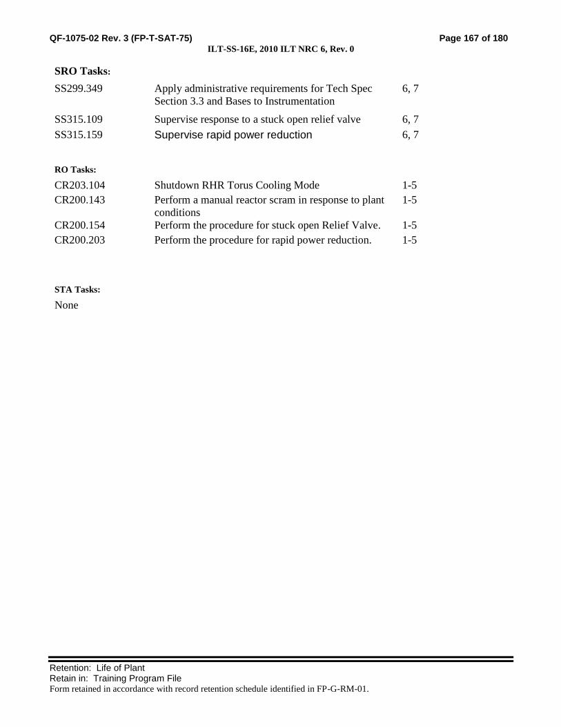
QF-1075-02 Rev. 3 (FP-T-SAT-75) Page 167 of 180 ILT-SS-16E, 2010 ILT NRC 6, Rev. 0
Retention: Life of Plant Retain in: Training Program File Form retained in accordance with record retention schedule identified in FP-G-RM-01.
SRO Tasks:
SS299.349 Apply administrative requirements for Tech Spec
Section 3.3 and Bases to Instrumentation
6, 7
SS315.109 Supervise response to a stuck open relief valve 6, 7
SS315.159 Supervise rapid power reduction 6, 7
RO Tasks:
CR203.104 Shutdown RHR Torus Cooling Mode 1-5
CR200.143 Perform a manual reactor scram in response to plant
conditions
1-5
CR200.154 Perform the procedure for stuck open Relief Valve. 1-5
CR200.203 Perform the procedure for rapid power reduction. 1-5
STA Tasks:
None

QF-1075-02 Rev. 3 (FP-T-SAT-75) Page 168 of 180 ILT-SS-16E, 2010 ILT NRC 6, Rev. 0
Retention: Life of Plant Retain in: Training Program File Form retained in accordance with record retention schedule identified in FP-G-RM-01.
QUANTITATIVE ATTRIBUTES (Use this form for Evaluations only.)
Malfunctions:
Before EOP Entry:
21. (Optional) Condenser Vacuum Switch failure / No ½ Scram
22. Stuck open SRV
After EOP Entry:
None
Abnormal Events:
17. Stuck open SRV
Major Transients:
None
Critical Tasks:
CT-6: When an SRV is stuck open and cannot be closed then insert a manual reactor scram.

QF-1075-02 Rev. 3 (FP-T-SAT-75) Page 169 of 180 ILT-SS-16E, 2010 ILT NRC 6, Rev. 0
Retention: Life of Plant Retain in: Training Program File Form retained in accordance with record retention schedule identified in FP-G-RM-01.
SCENARIO OVERVIEW:
INITIAL CONDITIONS:
20. IC 286, 100% Power
21. The initial plant conditions are:
Torus Cooling is in Service after RCIC Test
22. The following equipment is OOS
None
23. The following evolutions are planned for the shift:
Secure Torus Cooling
SEQUENCE OF EVENTS:
Event 1: (Optional) Secure Torus Cooling
BOP Secures Torus Cooling.
Event 2: (Optional) Condenser Vacuum switch Failure
Condenser Low-Vacuum switch fails. The annunciator alarms but the Channel A RPS logic fails to
trip, which requires insertion of a manual scram on A RPS.
Event 3: Stuck Open SRV
The B SRV opens and will not reclose.
Event 4: Rapid Power Reduction for Stuck Open SRV
The crew performs Rapid Power Reduction and, when the SRV remains open, manually scrams the
reactor.

QF-1075-02 Rev. 3 (FP-T-SAT-75) Page 170 of 180 ILT-SS-16E, 2010 ILT NRC 6, Rev. 0
Retention: Life of Plant Retain in: Training Program File Form retained in accordance with record retention schedule identified in FP-G-RM-01.
NOTE: Table may be modified as needed to include all scenario time-line items
SCENARIO TIME-LINE:
SEQ SEQUENCE OF EVENTS / INSTRUCTOR NOTES CREW
POS EXPECTED STUDENT RESPONSES
93. INITIAL CONDITIONS (IC):
ccc. IC: 286 (From IC 15)
ddd. Mode: 1
eee. Power: 100%
fff. Generator: 604 Mwe
ggg. Xcel system condition is GREEN
hhh. Plant CDF is GREEN
iii. River temp is 56°F and NO towers are in service
jjj. Outside temp is 60°F
kkk. A Loop of RHR is in Torus Cooling
94. SIMULATOR SET UP
z. Set the plant initial conditions per the Initial conditions under the Scenario Overview, Initial Conditions, and Manual Settings.
aa. Enter the malfunctions, remotes, overrides and event triggers per the “Simulator Input Summary”.
bb. Control Room and Shift Supervisor turnover checklists should be provided with the scenario IC.
cc. Core Damage Frequency (CDF) should be updated on the status board.
dd. Tech Spec Required Actions should be updated on the status board.

QF-1075-02 Rev. 3 (FP-T-SAT-75) Page 171 of 180 ILT-SS-16E, 2010 ILT NRC 6, Rev. 0
Retention: Life of Plant Retain in: Training Program File Form retained in accordance with record retention schedule identified in FP-G-RM-01.
SCENARIO TIME-LINE:
SEQ SEQUENCE OF EVENTS / INSTRUCTOR NOTES CREW
POS EXPECTED STUDENT RESPONSES
95. COMPLETE TURNOVER:
a. Review applicable current Unit Status
b. Review relevant At-Power Risk status
c. Review current LCOs not met and Action Requirements
d. Verify crew performs walk down of control boards and reviews turnover checklists.
e. Plant Staffing The following support is available:
Normal Weekday Night Shift
Operations: Normal crew compliment only
Maintenance: Available as needed or requested.
f. Shift Activities Engineering: Available as needed or requested.
1) Secure Torus cooling Management: Available as needed or requested.
96. SHIFT BRIEF
a. Role Play as necessary. Turbine Building status: CRS Leads the Shift Brief
36). 5 Condensate demins in service. ATC
BOP Participate in Shift Brief
37). C highest @ 4.0 psid.
38). All systems in Turbine building are normal.
b. Role Play as necessary. Rx Building status:
39). All systems in the Rx bldg are normal.
c. Role Play as necessary: Third Operator.:
40). Nothing to add. CRS Crew assumes the duty.

QF-1075-02 Rev. 3 (FP-T-SAT-75) Page 172 of 180 ILT-SS-16E, 2010 ILT NRC 6, Rev. 0
Retention: Life of Plant Retain in: Training Program File Form retained in accordance with record retention schedule identified in FP-G-RM-01.
SCENARIO TIME-LINE:
SEQ SEQUENCE OF EVENTS / INSTRUCTOR NOTES CREW
POS EXPECTED STUDENT RESPONSES
Event 1 97. (Optional) Secure Torus Cooling
Note: This event is OPTIONAL and has no bearing on the subsequent events. It may be omitted at the discretion of the Lead Examiner when the BOP candidate has had the requisite number Normal Events.
CRS Directs shutdown of Torus Cooling per B.03.04-05
BOP Slowly CLOSE MO-2008, Torus cooling Inject/Test Inboard
o Hold the MO-2008 handswitch to CLOSE for
approximately 5 seconds after the red indicating light
goes out
Close MO-2006, Discharge to Torus Outboard
Stop the A RHR Pump
Verify closed CV-1994, 11 RHR Pump Minimum Flow
Fully OPEN MO-2002, Heat Exchanger Bypass
o Verify MO-2002 handswitch is in the STOP
position.
ATC Independently verify the following valve positions:
o MO-2008 CLOSED
o MO-2006 CLOSED
o CV-1994 CLOSED
o CV-1996 CLOSED
o MO-2002 OPEN

QF-1075-02 Rev. 3 (FP-T-SAT-75) Page 173 of 180 ILT-SS-16E, 2010 ILT NRC 6, Rev. 0
Retention: Life of Plant Retain in: Training Program File Form retained in accordance with record retention schedule identified in FP-G-RM-01.
SCENARIO TIME-LINE:
SEQ SEQUENCE OF EVENTS / INSTRUCTOR NOTES CREW
POS EXPECTED STUDENT RESPONSES
a. Role Play Shift Chemist as necessary: Acknowledge the order to valve out the RHR Div 1 Conductivity Element
BOP Notify the Shift Chemist to valve out the RHR Div 1
Conductivity Element, CE-10-112A
BOP Stops the RHRSW system per B.08.01.03-5
o CLOSE RHRSW-32, LOOP A & B Crosstie
o Adjust the output of DPIC-10-130A to 0 to CLOSE
CV-1728, 11 RHR Hx RHRSW Outlet
o Stop the 11 RHRSW Pump
b. Role Play plant support personnel as necessary to Initiate procedure 2145
Initiate procedure 2145 (RHR SYSTEM DISCHARGE
VENTING)
NOTE: It is NOT intended for the crew to actually vent RHR or address TS for RHR Venting.
Event 2 98. Condenser Vacuum Switch Failure

QF-1075-02 Rev. 3 (FP-T-SAT-75) Page 174 of 180 ILT-SS-16E, 2010 ILT NRC 6, Rev. 0
Retention: Life of Plant Retain in: Training Program File Form retained in accordance with record retention schedule identified in FP-G-RM-01.
SCENARIO TIME-LINE:
SEQ SEQUENCE OF EVENTS / INSTRUCTOR NOTES CREW
POS EXPECTED STUDENT RESPONSES
a. When directed by the lead evaluator, Insert MANUAL TRIGGER 1.
Key Parameter Response: None
b. Verify the following go active: Key Expected Alarms: 5-B-20 (Condenser Low Vacuum Scram Trip)
a) MALFUNCTION (Annunciator Cry wolf) C-05-B20
Auto Actions: None, RPS A fails to trip.
ATC Responds to annunciator and reports to the CRS
c. Evaluator prompt when the operator goes around back to C-15; 5A-K2A in C-15 is deenergized 5A-K2B, C, & D are all energized
CREW Recognize ½ scram should have occurred and did NOT
CRS Refers to TRM 3.3.1.1 and enters Required Action A.2, Place
associated trip system in Trip, in 12 hours.
Provides crew brief
Directs ½ scram be inserted on „A‟ RPS
ATC Inserts ½ scram by depressing „A‟ manual scram pushbutton
Event 3 99. Stuck Open SRV
a. When directed by the Lead Examiner, insert MANUAL TRIGGER 3
Key Parameter Response: C-03 Amber light above F SRV will be ON,
at C-21 Temperature for F SRV on TR-2-166 will be elevated.

QF-1075-02 Rev. 3 (FP-T-SAT-75) Page 175 of 180 ILT-SS-16E, 2010 ILT NRC 6, Rev. 0
Retention: Life of Plant Retain in: Training Program File Form retained in accordance with record retention schedule identified in FP-G-RM-01.
SCENARIO TIME-LINE:
SEQ SEQUENCE OF EVENTS / INSTRUCTOR NOTES CREW
POS EXPECTED STUDENT RESPONSES
1) Verify the following Malfunction goes active: AP01B, Stuck Open SRV
Key Expected Alarms:C-3-9 (Auto Blowdown Relief Vlv Leaking)
Auto Actions: Reactor power and generator load decrease
BOP Implement C.4-B.03.03.A (Stuck Open Relief Valve)
Place handswitch 2E-S4B for SRV B in OPEN and then
return to the normal position.
Place handswitch 2E-S4B for SRV B in CLOSE.
Monitor and control Reactor pressure
CRS Direct Rapid Power Reduction when the SRV fails to close (See Event
4)
When the B SRV remains open, direct a manual scram of the reactor
Initiate 0444-B for Torus Heat Addition.
If Torus Water Temperature exceeds 90°F, enter C.5-1200, (Primary
Containment Control)
BOP Perform 0444-B for Torus Heat Addition
CT-6 When an SRV is stuck open and cannot be closed then insert a
manual reactor scram. ATC When directed, manually scrams the reactor
Event 4 100. Rapid Power Reduction for open SRV
CRS Supervises Rapid Power Reduction
ATC Performs Rapid Power Reduction per C.4.F
ATC Reduces recirculation flow

QF-1075-02 Rev. 3 (FP-T-SAT-75) Page 176 of 180 ILT-SS-16E, 2010 ILT NRC 6, Rev. 0
Retention: Life of Plant Retain in: Training Program File Form retained in accordance with record retention schedule identified in FP-G-RM-01.
SCENARIO TIME-LINE:
SEQ SEQUENCE OF EVENTS / INSTRUCTOR NOTES CREW
POS EXPECTED STUDENT RESPONSES
ATC Does NOT go below 35Mlb/hr
101. SCENARIO TERMINATION
a. The scenario may be terminated at the discretion of lead instructor/evaluator
Crew: Remain in simulator for potential questions from evaluator.
b. End the scenario by placing the simulator in FREEZE.
Crew: No discussion of scenario or erasing of procedure marking is allowed.

QF-1075-02 Rev. 3 (FP-T-SAT-75) Page 177 of 180 ILT-SS-16E, 2010 ILT NRC 6, Rev. 0
Retention: Life of Plant Retain in: Training Program File Form retained in accordance with record retention schedule identified in FP-G-RM-01.
SIMULATOR INPUT SUMMARY
Code Description
Event
Trigger Delay Ramp Initial Value Final Value
MALFUNCTIONS
C-05-B20 Condenser Low Vacuum scram Trip 1 None None 1 (True)
AP01B Safety Relief Valve (RV2-71-B) Fails Open 3 None None 1 (True)
Manual Settings:
52. Reset to IC 286
a. If necessary, IC 286 can be recreated as follows:
o Reset to IC15, (100% Power)
o Place A Loop of RHR in Torus Cooling with 11 RHR Pump and 11 RHRSW Pump per B.03.04-05 D.3
o Establish Event Triggers and Commands per the Simulator Input Summary.
53. Verify the Malfunctions match the Simulator Input Summary.
54. Perform the applicable sections of the SIMULATOR SETUP CHECKLIST.
55. Provide the following for the operating crew :
a. A scenario specific Form 3139, Control Room Shift Turnover Checklist
b. A scenario specific Form 3140, Shift Supervision Turnover Checklist

QF-1075-02 Rev. 3 (FP-T-SAT-75) Page 178 of 180 ILT-SS-16E, 2010 ILT NRC 6, Rev. 0
Retention: Life of Plant Retain in: Training Program File Form retained in accordance with record retention schedule identified in FP-G-RM-01.
Attach the following site-specific information as necessary:
Simulator Set-up Checklist (before and after training)
Pre-evaluation Brief Guide (for evaluations only)
Post-evaluation Critique (for evaluations only)
Turnover Log
Historical Record:

QF-1075-02 Rev. 3 (FP-T-SAT-75) Page 179 of 180 ILT-SS-16E, 2010 ILT NRC 6, Rev. 0
Retention: Life of Plant Retain in: Training Program File Form retained in accordance with record retention schedule identified in FP-G-RM-01.
Simulator Scenario Development Checklist
Mark with an X Yes or No for any of the following. If the answer is No, include justification for the no
answer or the corrective action needed to correct the discrepancy after the item.
56. The scenario contains objectives for the desired tasks and relevant human performance tools. Yes No
57. The scenario identifies key parameter response, expected alarms, and automatic actions
associated with the induced perturbations.
Yes No
58. The scenario content adequately addresses the desired tasks, through simulator performance,
instructor-led training freezes, or both.
Yes No
59. Plant PRA initiating events, important equipment, and important tasks are identified. Yes No
60. Turnover information includes a Daily At Power or Shutdown Safety Risk Assessment. Yes No
61. The scenario contains procedurally driven success paths. Procedural discrepancies are
identified and corrected before training is given.
Yes No
62. The scenario guide includes responses for all anticipated communications to simulated
personnel outside the Control Room, based on procedural guidance and standard operating
practices. Include estimated completion times and/or notes for use of time compression.
Yes No
63. The scenario includes related industry experience. SOER, SER and similar OE
recommendations are clearly identified and fully addressed.*
Yes No
64. The scenario guide incorporates verification of Operator Fundamental application.* Yes No
65. Training elements and specific human performance elements are addressed in the scenario
critique guide to be used by the critique facilitator. The critique guide includes standards for
expected performance.*
Yes No
66. For evaluations, it has been verified that without operator action the critical tasks will be
failed.
Yes No
Developer and Reviewer: Once checklist is completed and deficiencies are corrected, sign the cover page.
* For evaluations these items may be marked NO without justification.

QF-1075-02 Rev. 3 (FP-T-SAT-75) Page 180 of 180 ILT-SS-16E, 2010 ILT NRC 6, Rev. 0
Retention: Life of Plant Retain in: Training Program File Form retained in accordance with record retention schedule identified in FP-G-RM-01.
Simulator Scenario Validation Checklist
Mark with an X Yes or No for any of the following. If the answer is No, include an explanation after the
item.
36. The desired initial condition(s) could be achieved.
Yes
No
37. All malfunctions and other instructor interface items were functional and responded to
support the simulator scenario.
Yes
No
38. All malfunctions and other instructor interface items were initiated in the same
sequence described within the simulator scenario.
Yes
No
39. All applicable acceptance criteria were met for procedures that were used to support
the simulator scenario.
Yes
No
40. During the simulator scenario, observed changes corresponded to expected plant
response.
Yes
No
41. Did the scenario satisfy the learning or examination objectives without any significant
simulator performance issues, or deviations from the approved scenario sequence? If
learning objective(s) could not be satisfied, identify the objectives in the Simulator
Action Request
Yes
No
42. Evaluation: The simulator is capable of being used to satisfy learning or examination
objectives without exceptions, significant performance discrepancies, or deviation
from the approved scenario sequence.
Yes
No
Discrepancies noted (Check “none” or list items found) None
SMAR = Simulator Action Request
SMAR: SMAR: SMAR: SMAR:
Comments:
Validator: Sign the cover page only after noted discrepancies are corrected or compensatory actions are taken to ensure
quality training.