Monterey, California - apps.dtic.mil · CIMP Corporate Information Management Plan CNO Chief of...
101
AD-A245 776 NAVAL POSTGRADUATE SCHOOL Monterey, California DTIC 4 T'RAD3N THESIS THE DESIGN OF A PROTOTYPE PERSONAL COMPUTER DATABASE FOR THE EXPERT SYSTEM ADVISOR FOR AIRCRAFT MAINTENANCE SCHEDULING (ESAAMS) by Dennis K. Christensen and Magno 0. Pasadilla, Jr. December, 1991 Thesis Advisor: Martin J. McCaffrey Approved for public release; distribution is unlimited 92-03493 V2 2~ ' f
Transcript of Monterey, California - apps.dtic.mil · CIMP Corporate Information Management Plan CNO Chief of...

AD-A245 776
NAVAL POSTGRADUATE SCHOOLMonterey, California
DTIC 4 T'RAD3N
THESISTHE DESIGN OF A PROTOTYPE PERSONAL COMPUTER
DATABASE FOR THE EXPERT SYSTEM ADVISOR FORAIRCRAFT MAINTENANCE SCHEDULING (ESAAMS)
by
Dennis K. Christensenand
Magno 0. Pasadilla, Jr.
December, 1991
Thesis Advisor: Martin J. McCaffrey
Approved for public release; distribution is unlimited
92-03493V2 2~ ' f

UnclassifiedSecurity Classification of this page
REPORT DOCUMENTATION PAGEIa Report Security Classification Unclassified lb Restrictive Markings2a Security Classification Authority 3 Distribution Availability of Report
2b Declassification/Downgrading Schedule Approved for public release; distribution is unlimited.4 Performing Organization Rcl-orl Numberls) 5 Monitoring Organization Report Numberis)6a Name of Performing Organization 6b Office Symbol 7a Name of Monitoring OrganizationNaval Postgraduate School IafApplicabl) xx Naval Postgraduate School6c Address (ciy, state, and ZIP code) 7 b Address (cin., state, and ZIP code)Monterey, CA 93943-5000 Monterey, CA 93943-50008a Narm of Fuing/Sponasonng Organization 8b Office Symbol 9 Procurement Instrument Identification Number
I( ij l,_Bc Address (city, state, and ZIP code) 10 Soure of Funding Numbers
I unmi Numbe Pro,. No IT.&k No Woft jU.S Acme". No
I I Tife (Incde Secum.. Classfwion) The Design Of A Prototype Personal Computer Based Database For The ExpertSystem Advisor For Aircraft Maintenance Scheduling (ESAAMS), Unclassified12 Personal Authorts) Christensen, Dennis Karl and Pasadilla, Magno Obrero, Jr.13a Type of Report 13b Time Covered 114 Date of R rt (sea .mnr44, .15 Page CountMasters Thesis From To 1991-12-12 ecemuer, 1 1017.
16 Supplknenary Notation The views expressed in this thesis are those of the authors and do not reflect the officialpolicy or position of the D ment of Defense or the U.S. Government.17 Cosati Codes 18 Subject Terms (continue on reserse if necessarly and idenauf by block nwnber)
Field Group Subgroup ESAAMS, Expert System, Database Management System, NALDA, NALCOMIS,I Database. Aviation Maintenance
1 9 Abstract (coninue on reverse ifnecessar% and identifi by blik-k nwnber
The Expert System Advisor for Aircraft Maintenance Scheduling (ESAAMS) was originally proposed in 1985to assist in the scheduling of mai~atenance discrepancy repair in the organizational squadron environment. Thisdynamic environment produces a continuous flow of maintenance documentation from each maintenance action.Presently there exists no single system for the maintenance expert to retrieve this information to assist him, or her,in the critical maintenance decision making process.
This thesis addresses the design of the ESAAMS database which is of paramount importance to the expertsystem. Research on the use of the Naval Aviation Logistics Data Analysis (NALDA) database for a personalcomputer-based database is documented. Review of other existing naval aviation database systems are included inthis research. Based on interviews with experienced fleet aviation maintenance managers, a prototype databasedesign is produced. This thesis concludes with recommendations for further study based upon the findings of thisresearch.
20 DistributioniAvailabiht. of Abstract 21 Abstract Security Classification
X unclassifiedlurdhmnted same as repori DnC user, Unclassified'22a Name of Responsible Individual 22b Telephone (include Area code, 22c Office Symbol
Professor Martin J. McCaffrev (408) 646-2488 Code AS/MFDD FORM 1473. 84 MAR 83 APR edition ma, be used until exhaustCd secunt) classification of this page
All other editions are obsolete Unclassified

Approved for public release; distribution is unlimited.
The Design of a Prototype Personal Computer Database ForThe Expert System Advisor for Aircraft Maintenance
Scheduling (ESAAMS)
by
Dennis K. ChristensenLieutenant Commander, United States Navy
B.S., University of Florida, 1978
and
Magno 0. Pasadilla, Jr.Lieutenant. United States Navy
B.A.,University of Texas at Austin, 1984
Submitted in partial fulfillment of the requirements for thedegree of
MASTER OF SCIENCE IN MANAGEMENTMASTER OF SCIENCE IN INFORMATION SYSTEMS
trom the
NAVAL POSTGRADUATE SCHOOLDecember 1991
Authors:__ _ _ _ _ _ _ _ _ _ _ _ _ _ _ _ _ _ _ _ _ _ _ _ _ _ _ _ _
nis K. se
a .ano 0. Pasadilla, Jr.
Approved by:Martin J. Caffrey,/Pe Advisor
Balasubramanian esh, Second Reader
David R. 14%ipple, CrmanDeatent of Adrinistativ( ence
ABSTRACT
The Expert System Advisor for Aircraft Maintenance Scheduling (ESAAMS) was
originally proposed in 1985 to assist in the scheduling of maintenance discrepancy repair in
the organizational squadron environment. This dynamic environment produces a
continuous flow of maintenance documentation from each maintenance action. Presently
there exists no single system for the maintenance expert to retrieve this information to assist
him, or her, in the critical maintenance decision making process.
This thesis addresses the design of the ESAAMS database which is of paramount
importance to the expert system. Research on the use of the Naval Aviation Logistics Data
Analysis (NALDA) database for a personal computer-based database, is documented.
Review of other existing naval aviation database systems are included in this research.
Based on interviews with experienced fleet aviation maintenance managers, a prototype
database design is produced. This thesis concludes with recommendations for further
study based upon the findings of this research.
kccesion FGr
NTIS CI\A&jDUC: rA3
J,,s[. ic.aHivn
Bly
D -I l b iU ~ ~ -3c~1 L
By................
Ditihtei

TABLE OF CONTENTS
1. INTRODUCTION ............................................................ 1
A. BACKGROUND ....................................................................... 1
B. OBJECTIVES .............................................................................. 2
C. SCOPE, LIMITATIONS AND ASSUMPTIONS ................................. 2
D. RESEARCH METHODOLOGY ..................................................... 3
E. THESIS ORGANIZATION ........................................................... 3
1. THE AVIATION MAINTENANCE ENVIRONMENT .................... 5
A. INTRODUCTION ..................................................................... 5
B. THREE LEVELS OF MAP JENANCE ........................................... 61. Organizational Level ............................................................ 6
2. Intermediate Level ............................................................... 7
3. Depot Level ...................................................................... 7
C. THE ORGANIZATIONAL MAINTENANCE ACTIVITY ..................... 7
1. Planned Maintenance System .................................................... 8
2. Maintenance Control ............................................................ 9D. AV-3M REPORTING .................................................................. 11
E. SUMMARY .............................................................................. 13
III. DATA BASE SYSTEMS .................................................. 14
A. INTRODUCTION ..................................................................... 14
B. DATABASE TECHNOLOGY ....................................................... 14
C. DATA BASE MODELS ................................................................ 151. Hierarchical Model .............................................................. 152. Network Model ................................................................. 163. Relational Model ............................................................... 17
4. Normalization ...................................................................... 20
5. Relationships ................................................................... 20
a. One-to-one Relationships ................................................ 20b. One-to-many Relationships ................................................. 21
c. Many-to-many Relationships ............................................. 21
D. WHY CHOOSE A RELATIONAL DATABASE MODEL FOR ESAAMS? ... ..22
iv
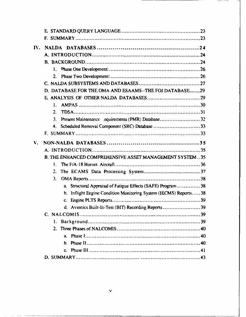
E. STANDARD QUERY LANGUAGE ...................................... 23
F. SUMMARY..............................................................23
IV. NALDA DATABASES............................................ 24
A. INTRODUCTION ....................................................... 24
B.BACKGROUND ......................................................... 24
1. Phase One Development: ............................................. 26
2. Phase Two Development: ............................................ 26
C. NAIDA SUBSYSTEMS AND DATABASES..............................27
D. DATABASE FOR THE OMA AND ESAAMS--THE FOJ DATABASE .....29
E. ANALYSIS OF OTHER NALDA DATABASES ......................... 29
1. AMPAS ............................................................ 30
2. TDSA............................................................... 31
3. Present Maintenance equirements (PMR) Database...................32
4. Scheduled Removal Component (SRC) Database......................33
F. SUMMARY..............................................................33
V. NON-NALDA DATABASES ....................................... 35
A. INTRODUCTION........................................................ 35
B. THE ENHANCED COMPREHIENSIVE ASSET MANAGEMENT SYSTEM.. 35
1. TheF/A-l8Hornet Aircraft .. ...................................... 362.The ECAMS Data Processing System ............................... 37
3. OMA Reports........................................................ 38
a. Structural Appraisal of Fatigue Effects (SAFE) Program........... 38
b. Inflight Engine Condition Monitoring System (IECMS) Reports..38
c. Engine PLTS Reports............................................ 39d. Avionics Built-hI-Test (BIT Recording Reports.................. 39
C. NALCOMIS..............................................................39
1. Background ......................................................... 39
2. Three Phases of NALCOMIS ........................................ 40
a. Phase I ......................................................... 40
b. Phase 1 ......................................................... 40
c. Phase Ill........................................................ 41
D. SUMMARY .............................................................. 43
V

VI. USER INPUT .................................................... 45A. INTRODUCTION ....................................................... 45B. INTERVIEW INFORMATION............................................ 46
1. Scheduled Mainteriance...............................................46
2. Unscheduled Maintenance............................................ 48
3. Real Time Computing ................................................ 49
4. NALDA Data Use.................................................... 49
5. NALDA Accuacy .................................................... 49
6. What About NALCOMIS? ........... . . . . . . . . . . . . . . . . . . . . . . . . . . . . . . . . 50
7. User-Friendly System ................................................ 50
8. Other Findings ..................................................... 51
C. SUMMARY............................................................... 51
N"11. DBMS PROTOTYPE DESIGN.................................... 53A. INTRODUCTIION......................................................... 53
B. DEFINITION PHASE..................................................... 541. Scope ............................................................... 54
2. Feasibility........................................................... 55
C. REQUIREMENS PHASE................................................ 55
1. Database Objects..................................................... 56
a. MaintenianceAction ............................................. 58
b. EndItem....................................................... 58
c. Equipment-.Summary ........................................... 58
d. [ncorporated-TD)................................................58
e. JobID ......................................................... 59
2. Methodology ........................................................ 59D. EVALUATION ........................................................... 59
E. DESIGN ................................................................. 60
1. Logical Database Design ............................................ 60
a Relationship between parent End_-Item and siblings
MaintenanceAction and EquipmentLSummary ................... 60
b. Relationship between parent Maintenance_-Action and siblingsfIcorporated - D, and Job-ID, ................................... 60
c. Relationship between parent JOB.JD and siblingMaintenanceAction ............................................. 61
vI
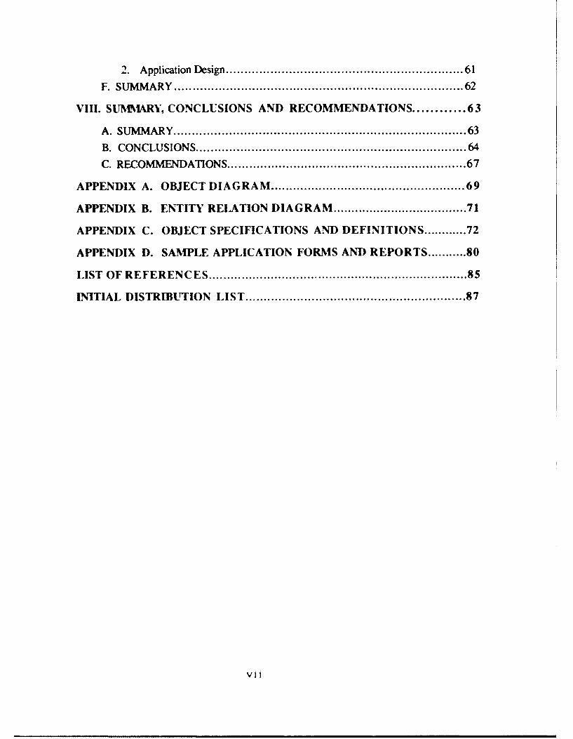
2. Application Design ........................ .........61
F. SUMMARY..............................................................62
VIII. SUMMIARY, CONCLUSIONS AND RECOMMENDATIONS ......... 63
A. SUMM4ARY............................................................... 63
B. CONCLUSIONS .......................................................... 64
C. RECOMNfHUDATIONS ................................................... 67
APPENDIX A. OBJECT DIAGRAM ......................................... 69
APPENDIX B. ENTITY RELATION DIAGRAM ............................ 71
APPENDIX C. OBJECT SPECIFICATIONS AND DEFINITIONS ........ 72
APPENDIX D. SAMPLE APPLICATION FORMS AND REPORTS........ 80
LIST OF REFERENCES........................................................85
INITIAL DISTRIBUTION LIST................................................ 87
vii

ACRONYMS AND NOMENCLATURE
4GL Fourth Generation Language
ADA A Procedural Language
ADS Automated Data System
AEMS Aircraft Engine Maintenance System
AIMD Aircraft Intermediate Maintenance Department
AMEN Aircraft Maintenance Engineering System
AMO Assistant Maintenance Officer
AMPAS Analytical Maintenance Program Support
ANSI American National Standardization Institute
ASCII American Standard
ASO Aviation Supply Office
ASR Aircraft Service Record
AV-3M Aviation Maintenance Material Management
BIT Built-in Test
BUNO Bureau Number
BU/SERNO Bureau Number/Serial Number
CDB Central Database
CIMP Corporate Information Management Plan
CNO Chief of Naval Operations
CODASYL Conference on Data Systems Languages
CSA Configuration Status Accounting
D-Level Depot Level
DBMS Database Management System
viii
DBTG Database Task Group
DLJI Data Language I
DOJ Deport Originated Jobs
DSF Data Services Facility
EBCDIC An IBM Machine Language
ECAMS Enhanced Comprehensive Asset Management System
EGT Exhaust Gas Temperature
EMT Elapsed Maintenance Time
EPU ECAMS Processing Unit
ESAAMS Expert System Advisor for Aircraft Maintenance Scheduling
ETR Engine Transaction Report
FIRAMS Flight Indicator Recording and Monitoring System
FOJ Fleet Originated Jobs
GE General Electric
I-Level Intermediate Level
ICRL Individual Component Repair List
IECMS Inflight Engine Condition Monitoring System
IMA Intermediate Maintenance Activity
IS Information System
JCN Job Control Number
LETR Last Engine Transaction Report
LSAR Logistic Support Analysis Record
LUI Life Used Indices
MAL Malfunction
MC Maintenance Chief
ix

MCC Maintenance Control Chief
MDCS Maintenance Data Collection System
MDS Maintenance Data System
MENS Mission Essential Needs Statement
MHRS Man Hours
MMCO Maintenance Material Control Officer
MMP Monthly Maintenance Plan
MO Maintenance Officer
MRC Maintenance Requirement Card
MSDRS Maintenance ,tatus Display and Recording System
MU Memory Unit
MV Multi-Value
NADEP Naval Aviation Depot
NADIS Naval Aviation Depot Information System
NADOC Naval Aviation Depot Operations Center
NALCOMIS Naval Aviation Logistics Command Management Information
System
NALDA Naval Aviation Logistics Data Analysis
NAMP Naval Aviation Maintenance Program
NAMO Naval Aviation Maintenance Office
NAMSO Naval Aviation Maintenance Support Office
NAVAIR Naval Air Systems Command
NAVFLIRS Naval Flight Record Subsystem
NAVMASSO Na\vy Management Systems Support Office
NIC NALDA Interface Computer
x

NPS Naval Postgraduate School
NRMM NALCOMIS Repairables Management Module
NSLC Naval Supply Logistics Center
O-Level Organizational Level
0CM On-Condition Maintenance
OMA Organizational Maintenance Activity
PC Personal Computer
PLTS Parts Life Tracking System
PMR Periodic Maintenance Requirements
PMS Planned Mai. tenance System or Preventive Maintenance System
RCM Reliability Centered Maintenance
RFI Ready For Issue
SAF Support Action Form
SAFE Structural Appraisal of Fatigue Effects
SCIR Subsystem Capability and Impact Reporting
SE Support Equipment
SNT Serial Number Tracking
SQL Structured Query Language
SRA Shop Replaceable Assembly
SRC3M Scheduled Removal Component Maintenance and MaterialManagement
SSC Supply Support Center
TD Technical Directive
TDAIR Technical Directives Status Account (Aircraft)
TDCGS Technical Directives Status Account (Components and SupportEquipment)
xl

TDENG Technical Directives Status Account (Engines)
TDHER Technical Diretives Status Account (Hstorical Engines)
TDHS Technical Directives Status Account (Historical Aircraft)
TDSA Technical Directives Status Account database
TEC Type Equipment Code
TIM Tape Transport Magazine
TYCOMS Type Commanders
VIDS/MAF Visual Information Display SystemlMaintenance Action Form
WRA Weapons Replaceable Assembly
WUC Work Unit Code
xii

1. INTRODUCTION
A. BACKGROUND
Today's Navy and Marine Corps maintenance managers are faced with systems which
are continuously becoming more sophisticated and complicated to maintain. Guided by the
Naval Aviation Maintenance Program (NAMP), the maintainer is responsible each day for
optimizing the operational availability of his or her assigned assets. To accomplish this
monumental task a continuous flow of information must be readily available to himlher to
make accurate and timely decisions.
Over the years, access to information has been limited to local records and feedback
reports (forwarded from data processing facilities) that are 60 to ) days old. In today's
dynamic maintenance environment this way of doing business is no longer acceptable for
the maintenance manager. In an age of automated information systems and eal time access
to records, a reliable information system is not only possible, but must be made available to
maintenance managers.
The Expert System Advisor for Aircraft Maintenance Scheduling (ESAAMS)
introduced by McCaffrey [Ref. 1 in 1985, is the key to the way maintenance information
can be processed and put to use in the Navy of the 21 st century. This system concept
incorporates the use of an expert system to use the information generated in the
organizational aviation maintenance activity to assist in the scheduling of the daily
maintenance workload.
This thesis is a follow-on to research previously conducted which will ultimately
produce the personal computer (PC) based ESAAMS system. This research will directly

build on the earlier work of McCaffrey [Ref. i] and Burpo [Ref. 21 and to a lesser extent
on the works of Chase [Ref. 31 and Stone [Ref. 41.
B. OBJECTIVES
The objective of this thesis is to review the contents of Naval Aviation Logistics Data
Analysis (NALDA) database and other aviation maintenance database systems, and design
a PC-based prototype database for ESAAMS using NALDA data. Potential links to other
data management systems will also be investigated.
The following primary research questions will be addressed:
" What data contained in the NALDA database system are germane for use in buildingthe ESAAMS main database?
" What uses/benefits would such a database provide an organizational maintenanceactivity?
Secondary research questions include:• Are other databases in addition to NALDA required for the proper operation and
maximum benefit of ESAAMS?" What do the "experts" in the aviation maintenance community want from a
management information system?
C. SCOPE, LI[MITATIONS AND ASSUMPTIONS
Development of the ESAAMS concept is so broad that this thesis will only address
issues involving ESAAMS database design. This research concludes with
recommendations for future use of the ESAAMS database structure as a standalone DBMS
and the future of ESAAMS in general. Design and discussion of other essential
components of the ESAAMS system are deferred for future research projects.
User input for this research was conducted in an informal question and answer format.
The sample was limited to personnel assigned to the activities addressed below and the
interview format was structured to allow a subjective vice objective input. While this form
of sampling is not scientific by nature, the authors feel that the views and opinions of those
2

interviewed do reflect some of the primary concerns of the experts assigned within the F/A-
18 community. These opinions and views do not necessarily encompass views and
opinions from all aviation maintenance communities Navy-wide.
D. RESEARCH METHODOLOGY
Data collection for this project was conducted both on-site and through telephone
conversations. Activities contacted include: NAVAIR Program Manager Air 270 (PMA-
270); Naval Aviation Maintenance Office (NAMO-42); Commander Strike Fighter Wing
Pacific Fleet Code 70; Naval Aviation Maintenance Training Group Detachment
(NAMTRAGRUDET) Lemoore, CA; Aviation Intermediate Maintenance Department
(AIMD), Naval Air Station Lemoore, CA.; Strike Fighter Squadron 25 (VFA-25); Strike
Fighter Squadron 113 (VFA-113); members of the NALDA Users Assistance
Group.(NAMO-622C); and a cadre of Aerospace Engineering Duty Officers assigned to the
Naval Postgraduate School, Monterey, CA.
A thorough review of current fleet instructions, fleet system proposals and supporting
program literature was conducted to provide the most current system and program status.
Information assembled includes some yet unpublished research material to reflect the state-
of-the-art in current Navy management information system development.
Description of the aviation maintenance process was based on the governing aviation
maintenance instructions and the authors' personal experience at three types of Naval
aircraft squadrons, and an Aircraft Intermediate Maintenance Deprtment (AIMD).
E. THESIS ORGANIZATION
The remaining chapters of this thesis are as follows:
II. DATABASE SYSTEMS. A general discussion of database and Database
Management Systems (DBMS). DBMS concepts and objectives, database models,
relationships, and database manipulation are discussed.
3

EI. THE AVIATION MAINTENANCE ENVIRONMENT. A brief description of
the Naval Aviation Maintenance Program (NAMP) and how it relates to an Organizational
Maintenance Activity (OMA) are discussed. The basic levels of maintenance and
maintenance data reporting are examined.
IV. NALDA DATABASES. A look into the NALDA program history, database
structure, contents, and applicability to ESAAMS are examined.
V. NON-NALDA DATABASES. An examination of other databases available to the
maintenance expert and for possible interface with ESAAMS is conducted. A brief
background and future uses for each database system are provided.
VI. MAINTENANCE COMINUNITY USER INPUT. Reactions of experts to the
ESAAMS concept and potential uses of the NALDA database are examined.
VII. DATABASE DEVELOPMENT AND PROGRAM DESIGN. Design and
construction of a prototype database and DBMS compiled from the NALDA database
system is examined.
VIII. CONCLUSIONS AND RECOMMENDATIONS. A summary of research
question findings and future concernsfrecommendations are provided.
4
!1. THE AVIATION MAINTENANCE ENVIRONMENT
A. INTRODUCTION
Naval Aviation Maintenance is a dynamic and constantly changing field. From a land-
based, routine training flight to the high tempo of carrier-based flight operations, the
squadron maintenance department is responsible for providing safe, mission capable (MC)
aircraft on a continual basis. The success, or failure, of an aviation squadron can, and
usually does, rest on the professionalism and expertise of the maintenance department. It is
essential that critical decisions arc made in a timely, accurate and precise manner. To
accomplish this monumental task, the maintenance "expert" must have the right information
available in the right place at the right time.
Presently, critical decisions are made under the guidelines of the Naval Aviation
Maintenance Program (NAMP) and from a combination of experience, governing
instructions, and expert knowledge. This decision making process is applied to every
maintenance action. The resulting action is recorded and sent upline as maintenance data-
With the vast quantities of data that are transmitted upline each day by every maintenance
organization, there remains no single retrieval source for this data to assist the
organizational maintenance expert in making day-to-day scheduling decisions. The current
information system environment is incapable of producing the types of information needed
to optimize squadron mission readiness decisions. An expert system, such as ESAAMS,
requires access to this wealth of data available in both the Navy's Aviation Maintenance and
Material Management System (AV-3M) and the Naval Aviation Logistics Data Analysis
(NALDA) system. Specifically, ESAAMS will require the average elapsed maintenance
5

time to remove and replace a part, and the historical failure rate of a component in relation
to other components in an aircraft system.
B. THREE LEVELS OF MAINTENANCE
To fully understand the scope of the NAMP it is important to understand the
environment of aviation maintenance. The NAMP objective is "...to achieve and
continually improve aviation material readiness...with optimal use of material, manpower,
and funds."[Ref. 5: p. 2-11 This objective is translated into a primary philosophy which is
to repair equipment at the maintenance level, which ensures optimal economic use of
resources.
The NAMP divides aviation maintenance into three distinct levels, each level linked to
the other through the Naval Supply System. The three levels of repair are the
organizational level (0-level), intermediate level (1-level), and the depot level (D-level).
1. Organizational Level
The organizational level encompasse; maintenance traditionally considered to be
the most basic and simple tasks required for repair of assigned aviation equipment [Ref. 6:
p. 1081. 0-level maintenance functions include inspection, servicing, handling, on-
equipment corrective and preventive maintenance, technical directive compliance, and
administrative record keeping and reporting [Ref. 5: p.3 -11. Truly, the other two levels are
of limited value without a properly managed and operated maintenance program at the
Organizational Maintenance Activity (OMA). 0-level maintenance of assigned equipment is
the responsibility of the using or reporting activity. The success of the maintenance effort
directly affects aircraft availability and Naval aviation readiness. The importance of a high
readiness state cannot be over-emphasized.
6
2. Intermediate Level
The intermediate level of maintenance concentrates on calibration, repair or
replacement of damaged or unserviceable parts, components or assemblies; the
manufacture/fabrication of non-available parts; and the provisions for technical assistance to
O-level activities. Maintenance is accomplished in an off-equipment environment dealing
mainly with major system and sub-system aircraft components. The I-level directly
supports the O-level by repairing and then returning parts to the supply system.
3. Depot Level
The third level of repair is preformed at Naval Aviation Depots (NADEP) or by
NADEP field teams sent to accomplish on-site repair. D-level maintenance represents the
highest level of repair and accomplishes both in-depth on-equipment and off-equipment
repair and modifications. Maintenance at this level consists of major overhaul (rework) or
complete re-manufacturing of parts, assemblies, subassemblies, and end-items, including
the manufacture, modification, testing. and reclamation of parts as required. [Ref. 7 p.3 -21
D-level maintenance supports the other two levels of maintenance directly and through the
supply system.
C. TlE ORGANIZATIONAL MAINTENANCE ACTI'ITY
Our focus in this thesis is on the organizational level or OMA. The most common
OMA is the aviation squadron. We will concentrate our attention and research here. Chase
(Ref. 3] points out "...the two broad areas of aircraft maintenance are--a Planned
Maintenance System (PMS) and a Maintenance Data System (MDS)." Both of which are to
"insure the highest state of aircraft readiness and reliability at the lowest cost in men,
money. and material." [Ref.8: p. 1-31
In addition to the scheduled requirements, the maintenance manager is faced with a
daily array of unscheduled requirements to maintain aircraft availability. This area of
7
aviation maintenance typically absorbs a greater part of the total maintenance time than does
scheduled maintenance.
The MDS is a management information system designed to provide statistical data for
use at all aviation maintenance and management levels. The system collects data from
every maintenance action performed on an aircraft or component of an aircraft or support
system. The data also includes input about parts availability and usage, man-hours
expended in the repair process, equipment configuration, and flight information.
The system is designed so that each worker, when performing a job, converts a
narrative description of the job into codes and enters coded information on standard forms
or source documents. These source documents are collected and transmitted to a data
services facility (DSF) where information is converted into machine records. The DSF
then uses the machine records to produce periodic report listings summarizing the
submitted data. These reports are supplied to maintenance supervisors to provide assistance
in planning and directing the maintenance effort. [Ref 10- p. 2-11
1. Planned Maintenance System
The Planned Maintenance System (PMS) is an aircraft-specific maintenance plan
which specifies applicable maintenance actions to be performed at predetermined
(scheduled) intervals. Contained in a series of publications, it specifies the minimum
maintenance that must be accomplished, the scheduled maintenance. [Ref. 3] The
publications provide a basis for planning, scheduling, and actual performance of scheduled
maintenance requirements. (Ref. 9 pp. 10-211 The PMS is the responsibility of the
Maintenance Department within each squadron. Adherence to the PMS optimizes aircraft
life and safety of operation during its life cycle. It ensures, when properly conducted, that
"all aeronautical equipment receive required servicing, preventive maintenance, and
inspection." [Ref. 9: p. 6-51
8

2. Maintenance Control
The first principle of maintenance is: Maintenance Control must control
maintenance! While sounding like a play on words, this corollary is the foundation of
the success or failure of the entire maintenance program. Maintenance control is the focal
point, "control center", of the squadron maintenance program. In this "hub" of the
Maintenance Department, the maintenance workload is coordinated and prioritized.
Maintenance tasks are then assigned to each supporting work center to fulfill the days
requirements. See Figure 2-1 below.
Maintenance control's responsibility does not apply only to the PMS and
unscheduled maintenance. A primary mission of every OMA is to meet the daily flight
schedule! To accomplish this task a combination of variables must be considered:
• Daily flight schedule aircraft requirements
• Scheduled maintenance requirements (calendar/phase inspections. etc.)
" Daily array of unscheduled "gripes" for each aircraft
" Personnel requirements (work center manning, training. etc.)
" Support equipment availability
" Parts availability (repairable/consumable)
" Future command requirements (detachments/deployments)
" Requirements specified by higher authority (inspections, special exercises, technicalbulletins/directives)
" Support facility availability (IMA personnel available, holidays, etc.)
All of these variables must fit into a "master schedule" and be precisely coordinated to
maximize readiness and aircraft availability. This is maintenance control's biggest task.
This major undertaking is the responsibility of the Maintenance Officer (MO) and
his direct subordinates. The master plan, commonly known as the maintenance plan, is
normally developed by the senior enlisted member in the maintenance control division, the
Maintenance Master (or Senior) Chief (MMC), in concert with the Maintenance/Material
Control Officer (MMCO); the Assistant Maintenance Officer(AMO), where personnel or
9
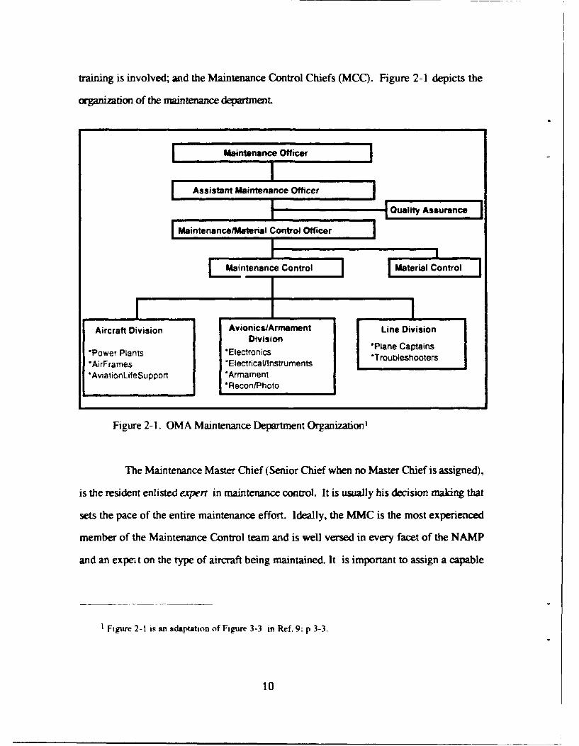
training is involved; and the Maintenance Control Chiefs (MCC). Figure 2-1 depicts the
ognization of the maintenance departmet.
MaintenancelMaterial Control Officer
Maintenance Control Material Control
*AirFrames *Electricalllnstruments *TroubleshootersAvialionLifeSupport *Armament
*ReconlPhoto
Figure 2-1. OMA Maintenance Department Organization'
The Maintenance Master Chief (Senior Chief when no Master Chief is assigned),
is the resident enlisted expert in maintenance control. It is usually his decision making that
sets the pace of the entire maintenance effort. Ideally, the MMC is the most experienced
member of the Maintenance Control team and is well versed in every facet of the NAMEP
and an expei, t on the type of aircraft being maintained. It is important to assign a capable
IFigure 2-1 is an adaptation of Figure 3-3 in Ref. 9: p 3-3.
10
leader who can maintain the continuity between maintenance control and the maintenance
production work centers, which may also have Chief Petty Officers (CPOs) assigned.
Working directly for the MMC are the MCCs who generally manage the "leading
edge" or minute-by-minute flow of maintenance. Their decision making process is made in
real-time, commonly spIit second, input from the entire maintenance arena. They put the
maintenance plan into effect but must vary their structure as internal and external influences
demand.
The Maintenance/Material Control Officer and the Maintenance Master Chief are
generally involved with the program in a broad sense. Master scheduling and long range
strategic planning typically absorb a arge quantity of their time. Deriving and publishing a
monthly schedule of maintenance, not surprisingly known as the Monthly Maintenance
Plan (MMP), reflects this strategic planning. These two individuals are widely considered
to be the experts in the maintenance environment. Their combination of maintenance
experience, understanding of the NAMP, and knowledge of the aircraft, make them
invaluable to the maintenance process.
D. AV-3M REPORTING
The Maintenance Data System and one of its major sub-groups. the Aviation
Maintenance and Material Management (AV-3M) System, provides the principal means for
the collection of maintenance data. Data is collected from every maintenance action
performed on every item of aeronautical equipment processed at the 0 and I-levels,
including some input from D-level actions.
Reporting of maintenance actions accomplished at the O-level is primarily directed into
the Naval Aviation Maintenance and Material Management (AV-3M) System by the use of
OPNAV Form 4790/60. the Visual Information Display System/Maintenance Action Form
(VIDS/MAF) and OPNAV Form 4790/42. Support Action Form (SAF). These documents.
11

(referred to as source documents) are screened for accuracy at the OMA and submitted to
the local Data Services Facility (DSF). This is commonly known as the local cycle.Ref.
10: para 2.1.31
The source documents are again screened, corrected, and converted into ASCII or
EBCDIC machine language at the DSF. When the documents have been verified, the
information is transmitted to the Naval Aviation Maintenance Support Office (NAMSO)
where it is compiled with input from all other DSFs. NAMSO then provides AV-3M
monthly feedback reports to the originating activities. It also sends the data to the Naval
Aviation Logistics Data Analysis (NALDA) database. This is the central repository of
aviation maintenance data. Figure 2-2 depicts the current AV-3M data flow. The Enhanced
Comprehensive Asset Management System (ECAMS) will be discussed in Chapter V.
Further discussion of NALDA will be reserved for Chapter IV.
12

IASOA-MDSF NSLC ASO
I t V NALDAAFlet, AMSOR Databases
andAV-31M ApicloH:s
F404
ECAMS ECAMS
Figure 2-2. Current AV-3M Data Flow
E. SUNMARY
The dynamic environment of naval aviation maintenance requires the maintenance
expert to make split-second decisions accurately and with professional confidence. To
accomplish this task, he or she must be provided with the right information at the right time
in the right place. There is a wealth of historical information available in the NALDA
database. The data consists of hundreds of maintenance actions that are accomplished
daily, processed for accuracy, and then are transmitted to the main NALDA database. The
processing of this data into information, and making it available to the maintenance expert,
could be a valuable asset to the planning and scheduling of organizational maintenance.
The composition and use of the NALDA database is the subject of the next chapter.
13

III. DATA BASE SYSTEMS
A. INTRODUCTION
This chapter introduces database and database management system concepts. An
expert system, such as ESAAMS, contains a knowledge base, an inference engine, and a
user interface. The knowledge base contains the rule base and access to the database. The
database is the repository of facts that, together with the rules in the knowledge base, will
be used by the inference engine for the expert system. Database management system
concepts and objectives, data models, relations, and how data is manipulated to perform
required applications, will be discussed.
B. DATABASE TECHNOLOGY
Before the introduction of database conco'. "- 5usinesses and organizations usedfile
processing systems to process recrrds and produce information. These systems stored
groups of records in separate files and processed them separately. Although these systems
were a great improvement from the iaborious manual processing, there are several
limitations:" Data is separated and isolated
" Data is often duplicated
" Application programs are dependent on file formats" It is difficult to represent complex objects using file processing systems [Ref. 11: p.
71
To overcome the limitations of file processing systems, database technology was
developed. A database is a collection of integrated, shareable, and non-redundant records.
These records are interrelated by specific relationships. [Ref. 12: p.51 An integrated
database provides an organization with greater access to information, better control and
14

easier program application development. David M. Kroenke and Kathleen A. Dolan define
a Database Management System (DBMS) as:
"...a program (or a set of programs) that allows stored data to be integrated,reduces data duplication, ensures data integrity, eliminates program dependency onfile formats, and allows complicated objects to be easily represented and retrieved.Briefly, a DBMS is a software system that is capable of supporting, manipulating,and managing a database."[Ref. 11: p. 9]
C. DATABASE MODELS
There are three basic data models or structures used in Database Management Systems:
hierarchical, network, and relational.
1. Hierarchical Model
The hierarchical data model represents data relationships using hierarchies or
trees. As Figure 3-1 illustrates, a tree or hierarchy consists of a number of nodes arranged
in a top-down sequence. Every node represents a data element. Every node is related to
another node at the next higher level. The higher node is called the parent and the nodes
below the parent are the children. A child can only have one parent but a parent can have
several children. The top-most parent is often labeled the root while the bottom most
children are called the leaves (hence, the name TREE). IBM first introduced this strcture
for use in their Data Language I (DL/I) DBMS.
15

Figure 3-1. Hierarchical Model
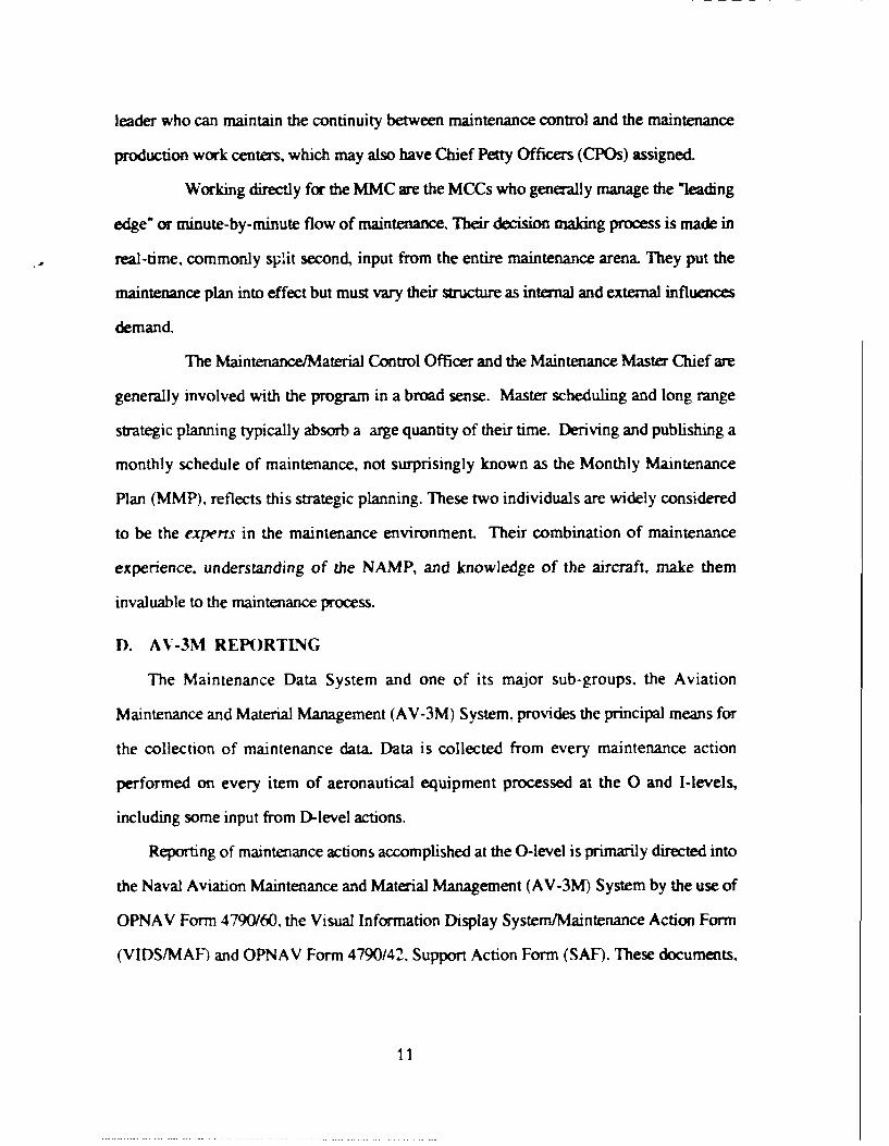
2. Network Model
In a network model, the degree of sophistication is carried up to the next level by
letting children have more than one parent. The basic hierarchical or tree structure approach
is still used. See Figure 3-2. The most widely known network model is the CODASYL
DBTG (Conference on Data Systems Languages, Data Base Task Group). The
development of CODASYL is very complex. The American National Standardization
Institute (ANSI) never adopted CODASYL as a national standard.
16
L'A
Figure 3-2- Network Model
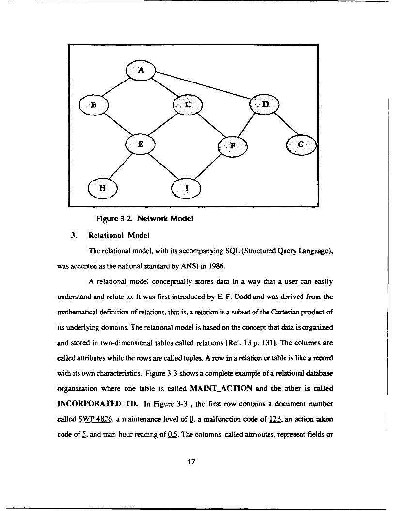
3. Relational Model
The relational model, with its accompanying SQL (Structured Query Language),
was accepted as the national standard by ANSI in 1986.
A relational model conceptually stores data in a way that a user can easily
understand and relate to. It was first introduced by E F. Codd and was derived from the
mathematical definition of relations, that is, a relation is a subset of the Cartesian product of
its underlying domains. The relational model is based on the concept that data is organized
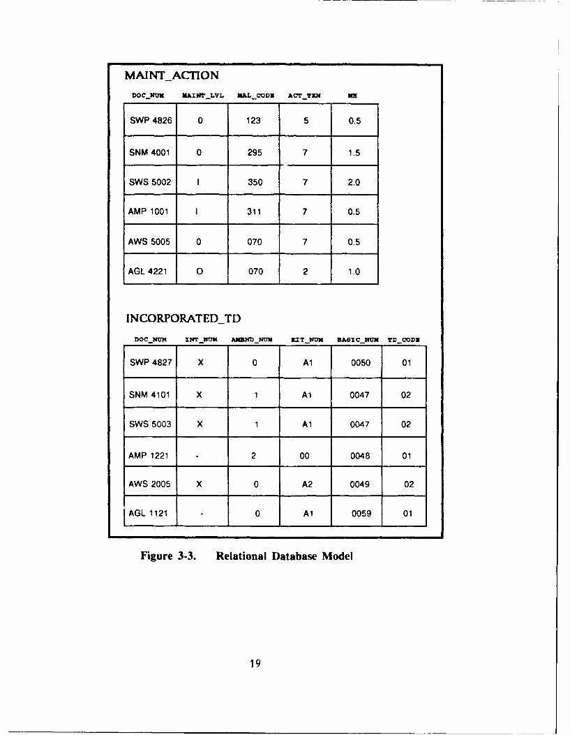
and stored in two-dimensional tables called relations [Ref. 13 p. 131]. The columns are
called attributes while the rows are called tuples. A row in a relation or table is like a record
with its own characteristics. Figure 3-3 shows a complete example of a relational database
organization where one table is called MAINT_ACTION and the other is called
INCORPORATED_TD. In Figure 3-3 , the first row contains a document number
called SWP 4826, a maintenance level of Q, a malfunction code of 123, an action taken
code of 5. and man-hour reading of 0.5. The columns, called attributes, represent fields or
17

data elements. So in Figure 3-3, the entries under DOC_NUM are fields of document
numbers, entries under MAINT_LVL are fields of maintenance levels, etc. The entire
table of rows and columns is roughly the equivalent of a file. A file contains records and
records contain fields or data elements. Unlike mathematical relations, however, database
relations are time-varying since tuples (rows) may be inserted, deleted, or updated [Ref.
11: p. 186]. In simple terms, we have a file of maintenance actions and another file of
incorporated Technical Directives.
Each tuple or row in a relation or table is identified by a key. A key is a group
of one or more attributes that uniquely identifies a row [Ref. 11: p. 1391. Going back to
Figure 3-3 once more, the first row of MAINTACTION can be uniquely identified by
the DOC_NUM SWP 4826. All the other rows have their own unique DOC_NUMs. It
is possible that a row can have more than one attribute that can become a key. These
attributes are called candidate keys and they can be composed of a primary key and
foreign keys. A primary key is an attribute that can uniquely identify a row or a tuple. A
foreign key is a candidate key that is taken from another table or relation and placed as an
attribute (column) in another table in order to form a relationship between the two tables.
These keys are selected to uniquely identify the row. In Figure 3-3, the table
INCORPORATED_TI) has two candidate keys, namely, DOC_NUM and
BASICNUM. INCORPORATED_TD is related to MAINT_ACTION through
DOCNUM. DOCNUM is a foreign key to INCORPORATED_TD since
BASIC_NUM can be its primary key. It is possible for the primary key and foreign key
to be the same. For instance, in Figure 3-3, DOCNUM can be the primary key for both
the INCORPORATEDTD and MAINTACTION since it can uniquely identify a
row from either table.
18
MAINTACTION
DOC NUN MIITLVL UAL CODE ACT YTI 3m
SWP 4826 0 123 5 0.5
SNM 4001 0 295 7 1.5
SWS 5002 1 350 7 2.0
AMP 1001 1 311 7 0.5
AWS 5005 0 070 7 0.5
AGL 4221 0 070 2 1.0
INCORPORATEDTD
DOC-NUN U4T NUN AJMNDNU KT_NUN SSICNUK TD_CODZ
SWP 4827 X 0 Al 0050 01
SNM 4101 X 1 Al 0047 02
SWS 5003 X 1 Al 0047 02
AMP 1221 2 00 0048 01
AWS 2005 X 0 A2 0049 02
AGL 1121 0 Al 0059 01
Figure 3-3. Relational Database Model
19

4. Normalization
Normalization is the process of gathering data items (or attributes) into relations.
The goal of a good logical database design is to represent objects or entities in the database
using relations that (1) provide the data needed to construct user objects (or tables) and (2)
are robust enough to allow rows to be inserted, deleted, and modified without resulting in
inconsistencies or errors in the stored data. [Ref. 11: p. 133-134]
5. Relationships
In order to have an efficient operation for a DBMS, proper data base design is
extremely critical. It is necessary to preclude an excessive amount of data redundancy,
inadvertent deletion of data, and presence of data anomalies. Correct relationships between
entities or objects are imperative to achieve a proper logical design. Relationships between
entities can be classified in three ways:
" One-to-one
" One-to-many
* Many-to-many
a. One-to-one Relationships
A one-to-one (1: 1) relationship is the simplest form. Given an Object A and
an Object B, a one-to-one relationship exists if A contains B as a single-valued property
(or attribute), and either B contains A as a single-valued property or B does not contain A.
Hence, there can only be one occurrence for an attribute in an object The key of one ofthe
relations must be stored as an attribute of the other in order to link them together. [Ref. 11:
pp. 169-174]
An example of this kind of relationship can be shown using Appendices A
and B. In Appendix A. the table or object MaintenanceAction is related one-to-one
20

(1:1) with the object IncorporatedTD. This is denoted by the absence of "my" or
multiple value after object Incorporated_TD inside the object MaintenanceAction.
In other words, for each occurrence of a MaintenanceAction there is only one
occurrence of IncorporatedTD. In Appendix B, the graphical logical representation of
the database shows the 1:1 relationship again by the straight line connection between these
two objects without the arrow tail. Note in Appendix B that the primary keys JCN and
WC of MaintenanceAction are used as foreign keys for IncorporatedTD.
b. One-to-many Relationships
A one-to-many (1 :N) relationship occurs when a record of one type is
related to potentially many records of another type. [Ref. 11: p. 174). The terms parent and
child are sometimes applied to records in one-to-many relationships. The parent record is
on the one side of the relationship and the child record is on the many side. The key of the
parent relation must be stored as an attribute of the child relation.
Using Appendices A and B to show an example of a one-to-many (I:N)
relationship, let's take the objects EndItem and MaintenanceAction. For every
occurrence of an EndItem there can be many MaintenanceActions. This follows the
same logic in the business environment of aviation maintenance. For every aviation end
item, which can be an aircraft system or part, there can be multiple maintenance actions
taken. Appendix A shows the I :N relationship between these two objects by the presence
of "mv" after MaintenanceAction inside the End_Item object. Appendix B shows
this relationship once more by the arrow tail symbol on MaintenanceAction.
c. Many-to-many Relationships
In a many-to-many (M:N) relationship a record of one type is related to
many records of the second type and a record of the second type is related to many records
of the first type. Many-to-many relationships cannot be directly represented in relations as
21

one-to-one (1:1) or one-to-many (I:N) relationships because deletion and insertion
anomalies will occur in the database. The solution to the problem is to create a third relation
that shows the correspondence of the object- This relation is called an intersection
relation. Each record in an intersection relation contains the keys of each of the related
records in the two relations. [Ref. 11: pp. 178-183]
Appendices A and B don't show a many-to-many relationship. To show an
example of a many-to-many relationship, let us take two imaginary objects called
Personnel and Squadron. Aviation personnel can belong to many squadrons (maybe
not at the same time) and a squadron can have many personnel. Since these two objects are
both multi-valued, in order to create a database relationship an intersection object must be
created. This object can be called SquadronPersonnel and will contain the keys of
each of the objects.
D. WHY CHOOSE A RELATIONAL DATABASE MODEL FOR ESAAMS?
As mentioned earlier, a relational database is stored conceptually in a way the user can
understand and access directly. Relations, being two-dimensional tables, are easier to
comprehend and deal with by non-programming oriented users. Users are presented with a
single and consistent data model or structure. There is no need for concern on the l:N
versus the M:N relationships as in the hierarchical and network models. The relationships
are stored in the data themselves.
There is more data independence, flexibility, database processing power, and security
in a relational model. The model permits relational completeness that can be transparent to
a non-technical user. It also facilitates good database design. Potential aviation
maintenance users will be able to comprehend the database structure better when designed
in the relational model vice a hierarchical or network model.
22
Unlike other database structures, relational databases make ad hoc queries
possible. Ad hoc means unpredicted. Other database models are not structured to answer
unpredicted questions easily. [Ref. 5: p. 296] The ability to ask ad hoc questions is
essential for a decision support system. ESAAMS can best benefit from a relational DBMS.
E. STRUCTURED QUERY LANGUAGE
The defactro language used in relational data manipulation is SQL (Structured Query
Language). SQL is a transform-oriented relational language. SQL provides a language to
transform input into desired output via relations. [Ref. 11: p. 3 2 1] SQL is not a procedural
language like ADA, Pascal, or C. 1 is a fourth-generation (4GL) data access language that
allows usage between different computers. Until now, transferring data from one computer
to another proved difficult because each computer had its own data sublanguage. With SQL
and its simple query/update language, data transfer between micros, minis and mainframes
can be faci'itated with ease. It is employed only to access data from a database and
manipulate it. SQL can be embedded in application programs.
F. SUMMARY
The ESAAMS expert system needs a database to provide information. An efficient
database model is essential for the optimal interaction between the database and the expert
system.
Three database models were discussed in this chapter to show the different methods
for constructing the database schema. The relational database is the model that this thesis
will use for the design and construction of the ESAAMS Database Management System.
Several applications that can be used by aviation maintenance managers will be generated to
show proper functioning of the DBMS.
23

IV. NALDA DATABASES
A. INTRODUCTION
The NALDA databases are uniquely qualified to serve as a foundation for essential
ESAAMS information [Ref. 2: p.4 91. Because NALDA is the central repository of data for
the naval aviation logistics and maintenance community, Burpo (1990) concluded to use the
NALDA databases, sometimes called the NALDA data bank, for the development of
ESAAMS. This chapter will cover NALDA's program history, databases and their
contents, and applicability to ESAAMS.
B. BACKGROUND
The Naval Aviation Logistics Data Analysis (NALDA) system evolved from the need
for improved data an:31v ib capabilities to support growth in sophistication and complexity
of Naval air we o,- . and associated support systems. Its primary objective is to (support)
centralized logistics data analysis. [Ref. 14: p.1] It also provides the capability to
accommodate upline reporting requirements as set forth in the Maintenance Data System
(MDS) program of the NAMP. The upline reporting is used to transport all maintenance
data and information from the OMAs. IMAs, and NADEPs to a central repository of data
for later retrieval.
The NALDA system is a centralized, integrated and uniform data bank providing
storage, retrieval and analysis capability. It is configured in a hierarchical database structure
using the Systems 2000 (S2K), developed by MR (Intel) Systems Corporation of Austin,
Texas, in the early 1970s, as its Database Management System. It can be used, in an
interactive manner, through remote terminals in support of the naval aviation logistics
community [Ref. 14: p. 11.
24
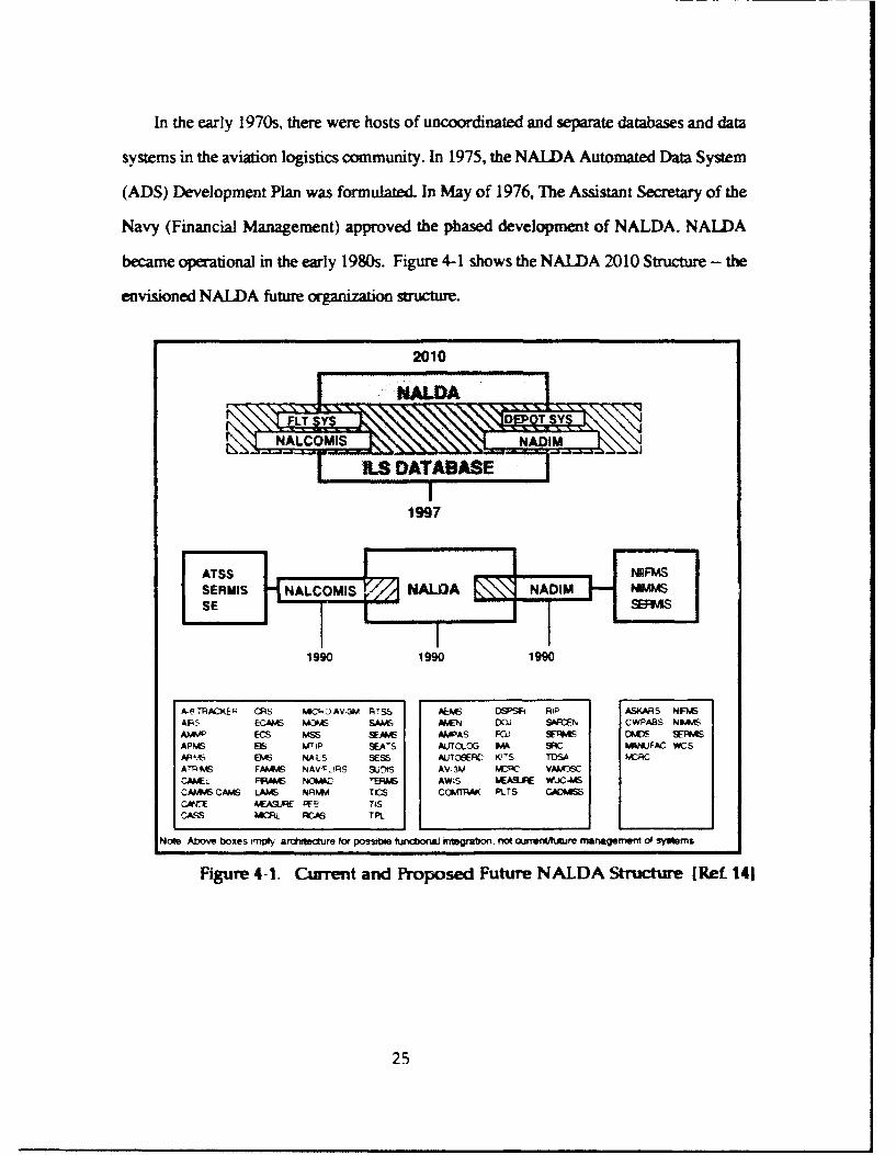
In the early 1970s, there were hosts of uncoordinated and separate databases and data
systems in the aviation logistics community. In 1975, the NALDA Automated Data System
(ADS) Development Plan was formulated. In May of 1976, The Assistant Secretary of the
Navy (Financial Management) approved the phased development of NALDA. NALDA
became opeational in the early 1980s. Figure 4-1 shows the NALDA 20 10 Structure - the
envisioned NALDA future organization structure.
2010
199
1990 1990 1990
A.- TRIKEA GRS t4CIP AVW3 RTSS AEVE OS'SI RiP ASKAR 5 NFN4SAFPS ECAPAS 4W ~ SAAA AWN DOJ SMEN CWPABS N&4AS
A* ECS MS SAM AWPAS FOJ SE;S DKIDS SEPMSAPG I M7Ip SEATS AU1'OOG FM SR WANFAC WCSAROS ENS NArLS SESS AUJTcSEFC KIS TOSA WRAP!S FM.9vS NAVX-TRS SUI AV-3V PKC VAMI
CAAC FF." NCM*Z ~TP41 AWLS LSR WUCAISCAA9. CA LA& NRNNv TICS Ca(!P.d PUTS C9DMI
CA- EASLPEE TISCASS k4 RC As TPL
Note Above boxes rmi;l archfteore for possibie ftindbon&l Mtegmt300 not offmerth~ure managemnei of rftems
Figure 4-1. Current and Proposed Future NALDA Structure MRet 141
25

1. Phase One Development:
NALDA's Phase One goal was the integration of three existing logistics data
systems: the Analytical Mamtenance Program Analysis Support (AMPAS) System, Aircraft
Maintenance Engineering (AMEN) System, and the Technical Directive Status Accounting
(TDSA) System. Phase One development also sought the creation of an intensified
maintenance data analysis capability. [Ref. 15: p.871 NALDA's target user community
includes:
" All Navy and Marine Corps Aviation Headquarters* Field Activities
" Type Commanders (TYCOMS)
" Fleet Activities (Intermediate Activities and above)
A very noticeable omission from the targeted user community are the
Organizational Maintenance Activities (OMA). Ironically, the originators of the data, at
present, receive little direct benefit from the NALDA database system. With ESAAMS,
NALDA will be able to expand its services directly to the organizations that provide the
bulk of the upline data. NALDA Phase One currently provides the following:" A Corporate Aviation Maintenance and Material Management database with on-line
interactive access Navy-wide;" Data analysis capability to perform Reliability Centered Maintenance (RCM);" Technical Directive Status Accounting (TDSA);
" Consolidation of the two original major NAVAIR Information Systems -- AMPASand AMEN.
2. Phase Two Development:
Phase Two NALDA objectives are expansions on Phase One and are an
opportunity to make significant life cycle cost reductions while incorporating needed
readiness improvements. Development started in early 1985 and is on-going with a
targeted full deployment date in late 1995.
26

Redundancy exists in the current aviation maintenance data collection system. AV-3M
data is collected at the various levels of maintenance, processed and sent to NAMSO,
Chesapeake, VA. At the same time, the same maintenance data is sent to the NALDA
database system located at ASO, Philadelphia, PA. Realizing this redundancy, the CNO
has directed NALDA to be the Navy's central upline logistics data system. The program
management team at NAMO has undertaken the AV-3M/NALDA merger. At this writing,
the program merger is on-going and is projected for completion in 1997. This merger will
do much to solve the redundancy problem and also greatly expedite the on-line query
process.
Objectives for Phase 11 include the following:
" Merger of common AV-3M functions supported by the Naval Sea Logistics Center(NSLC) and NALDA to eliminate redundancy;
" Addition of other logistics data like the Logistics Support Analysis Record (LSAR)and Configuration Status Accounting/Serial Number Tracking (CSA/SNT);
• Consolidation of other logistics information systems (ISs) to follow the OP-51Functional Sponsor Plan (FSP) directing NALDA to be the Navy's centralupline logistics data system;
* Improve user-friendliness by the introduction of relational DBMS.
C. NALDA SUBSYSTEMS AND DATABASES
The current Phase One NALDA operational system covers a whole spectrum of
different subsystems and databases to provide system users with information to solve
problems and make informed decisions. To date there are some 25 databases. Some of the
more prominent databases are listed below.
" Fleet Originated Jobs (FOJ) database: the principal repository of reportedmaintenance data from all OMAs, IMAs and Depots. There is one FOJ databasefor each aircraft type/model. plus additional databases for Support Equipment(SE). training devices, and other end items identified by a Type EquipmentCode (TEC).
" AMPAS system database: to implement and sustain the Phased MaintenanceProgram. This database became the vehicle for providing the analysisprocedures and techniques needed by Naval Air Systems CommandEngineering Support Office engineers, analyst managers and type commanders.
27

• AMEN database: developed from the FOJ database to provide in-house logisticsmanagers, engineers, and others throughout the logistics community with aneffective tool to identify and resolve aviation logistics problems.
" TDSA system database: an automated accounting system designed to store,maintain, and disseminate information concerning the status of TechnicalDirectives.
" Depot Originated Jobs (DOJ) database: a database to track maintenance actionscollected by the Depot Maintenance Data Collection System and originated at thedepots.
• Intermediatc Mintenance Activity (IMA) Analysis database: contains summary datathat enables analysis of the production effort at the intermediate level ofmaintenance and at an Aircraft Intermediate Maintenance Department (AIMD)for identified items.
" Present Maintenance Requirements (PMR) database: not yet completed. Willcontain data describing scheduled maintenance requirements at the 0- and I-levels.
" Training database: identical Lo FOJ except for the different values in the schemarecords. Data in this system pertains to training devices and equipment.
" Aircraft Engine Maintenance System (AEMS) database: contains informationderived from the Aircraft Engine Management System (AEMS) data system.This database consists of two separate and independent data systems, onecontaining propulsion system data and one containing propulsion systemmodule information. The system contains data from the Engine TransactionReport (ETR) and calculated data such as turn-around time, operating hours,etc.
* Last Engine Transaction Report (LER) database: contains information from AEMS.
" Aircraft/Equipment Summary Reports database: contains summary informationidentical to data reported in AV-3M information reports.
• Non-Maintenance Job Control Number Supply database: contains informationidentical to AV-3M information reports.
• Scheduled Removal Component database: contains information from ScheduledRemoval Component (SRC), Assembly Service Record (ASR), Module ServiceRecord (MSR) and Equipment History Forms (EHF) which are collected at theScheduled Removal Component Central repository.
" Master Index of Repairables database: contains item identification, evolution,applications, projected workload, modification and life limited replacementrequirements information as applicable for each repair item.
" Individual Component Repair List (ICRL) database: contains data which depicts thelevel of repair capability for each repairable at each Intermediate MaintenanceActivity. Fully compatible with IMA Analysis database.
• Code translation database: contains various translation codes; such as Work UnitCode (WUC), Type Equipment Code (TEC), and Malfunction Code (MAL),utilized in NALDA databases. [Ref. 14: p.2-31
28

D. DATABASE FOR THE OMA AND ESAAMS --THE FOJ DATABASE
Burpo (1990) asserted that the most likely database for ESAAMS is the FOJ database.
This conclusion was based from his interviews with different NALDA users. Research in
this thesis has uncovered other NALDA databases that are also useful to the OMA
maintenance expert. Their potential for inclusion into the PC-based expert system will be
evaluated and discussed fully in the next section.
The FOJ database stands to be the most logical and usable database for OMA use.
Chapter II, Section D discussed how data from the OMAs is sent upline using the the AV-
3M reporting system of the MDS. All this data ends up in the NALDA FOJ database
schema. All data taken from thtL VIDSIMAFs, training reports, safety-engineering
investigations, and depot summaries end up in the FOJ database. Hence, any historical
maintenance record of an aircraft or an aircraft system can be found in this single NALDA
database.
The database itself is enormous and not all data are germane to a maintenance manager.
The challenge, therefore, is to identify and extract the relevant data from the mainframe
hierarchical DBMS of NALDA and transfer them to a PC-based relational DBMS for use
by maintenance planners and ESAAMS.
E. ANALYSIS OF OTHER NALDA DATABASES
The feasibility study conducted by Burpo, IRef. 2], concludes that the FOJ database is
the most useful for application to ESAAMS because it contains elements necessary to assist
in the scheduling of maintenance. As pointed out, the NALDA system consists of many
databases each containing specific data. The question, from a maintainer's stand point
must be raised: Do any of these other databases hold information which can be effectively
used at the 0-level? Care must be exercised when examining the contents of a database.
29

One must not conclude just because it contains known useful data for the OMA, that the
data is also usable for ESAAMS.
Of the 16 databases listed above, only four contain specific data the authors feel is
germane to the OMA effort and therefore potentially of value to the ESAAMS database.
Many of the other databases contain data that is a duplicate of data already included in the
FOJ database and are not considered. The four useful databases are discussed below.
1. AMPAS
The Analytical Maintenance Program Analysis Support (AMPAS) system was
designed to provide a group of analysis procedures/techniques to NESC
Engineers/NAVAIR managers through a series of reports to solve day-to-day logistic and
management problems. The database is massive and encompasses two major subdivisions:
the Depot Maintenance Data Sub-System (DMDS) and the Maintenance Data Sub-System
(MDS). The MDS is further divided into three subcategories consisting of the Sub-System
Capability and Impact Report (SCIR) system, the Maintenance Data Reporting (MDR), and
3M Flight Data Reporting for aircraft utilization. [Ref. 16: p. 2]
The AMPAS database contains information from all three levels of maintenance.
Much of the data from the most recent 18 months is identical to data in the FOJ database. In
addition, it also contains a flight file (aircraft usage), depot and support equipment (SE)
information. This database also functions as an archive of maintenance information. Data
for all type of Naval aircraft are available from January of 1980 to the present. This data
can be readily retrieved for the user without going to the archives. Data on aircraft prior to
1980 is available by special request. The database is updated monthly but still suffers from
a 60-90 day delay for processing through the data collection network.
As mentioned, data contained in the AMPAS database reflects the same data in
the FOJ database specifically pertaining to the O-Level. The maintenance manager can use
30
this database to retrieve data which is more than 18 months old. For example, trend
analysis of EMT on a specific system can be conducted to reflect any changes, positive or
negative, over the life span of a weapon system.
While very useful historical information is available in the AMPAS system, the
processes of converting ten years of data, stored in a hierarchical structure, to a relational
database structure would be time prohibitive. Conversion time not withstanding, physical
storage space in a PC-based system could not possibly handle this quantity of information
on a stand-alone basis without an expensive, large capacity hard disk drive upgrade.
Information required from AMPAS should therefore be accessed through normal query
methods by certified NALDA users.
2. TDSA
The Technical Directives Status Account (TDSA) databases contain data
describing attributes of Naval Air Systems Command (NAVAIR) Technical Directives
(TD). The primary function is to store, mainta'n, and disseminate information concerning
the status of TDs. There is a TDSA database for aircraft (TDAIR), an engine database
(TDENG), and one for components and support equipment (TDCGS). The databases
contain detailed inventory records for all TDs reflecting the incorporated/not incorporated
status of applicable TDs. Historical databases are also maintained for TDs affecting aircraft
(TDHIS), engines (TDHER) and component/support equipment (TDHCG).[Ref. 17: p 11
In this research, the chosen aircraft (F/A- 18) has seen a multitude of TDs issued
for update and modification. From the aircraft inception, TD tracking has been one of the
most time and labor intensive functions of the Maintenance Control staff. Some OMAs
have even set up separate sub-work centers to manage TDs. The importance of properly
tracking the incorporation of TDs makes this data extremely important to the safety and
operation of the aircraft. While every OMA maintains a separate file of source
31

documentation concerning TDs, the authors find this database information important as a
cross check and management tool.
TD data is not solely contained in the TDSA databases, the FOJ databases also
contain data, reported on the VIDS/MAF, concerning the incorporation of TDs. This data
will be available through the FOJ-derived database, which is the primary focus of this
research. The TDSA database, much like the AMPAS database, is a historical archive of
data and contains data beyond the most recent 18 months as is the case with the FOJ
database.
The O-Level maintenance manager has the same opportunity to conduct trend analysis
as was the case with the AMPAS database. In this case, the TDSA enables him, or her, to
look back farther than the most recent 18 months for specific information pertaining to
technical directives. The NALDA Users Group, upon request, can furnish any batch report
on any TD incorporation and aircraft/engine configuration.
3. Present Maintenance Requirements (PMR) Database
The PMR database will contain data describing scheduled maintenance
requirements derived from the Maintenance Requirements Cards (MRC) decks [Ref. 18:
Sec V, p. 401. MRC decks contain the step-by-step maintenance actions of the PMS
program. This database will be updated periodically to reflect changes in maintenance
requirements or errors in the initial requirements recorded in the MRC decks. A database
containing this information is a major step in the automation of the PMS program. It
provides the OMA with an on-line system of scheduled maintenance requirement
information. The maintenance manager can verify his on hand type-aircraft MRC contents
with the data in the PMR to ensure accuracy. This database, while not available until the
late 1990s, will be extremely valuable in establishing the ESAAMS rule base and future
validation processes since it contains all scheduled maintenance requirements. To date,
32

PMR databases are only available for the F-14 and A-7E MRC decks. As of this writing
there is no target date mentioned for fleet-wide completion.
4. Scheduled Removal Component (SRC) Database
The SRC database contains information archived by part number, including data
provided by the depots. Each record is included in the database with an indicator
identifying the most current data for a component by part number and serial number. The
record includes data concerning installations, removals, overhauls, repairs, and technical
directive compliance.
A sub-database to this system is the SRC3M database. This database contains
data generated from the FOJ history files as recorded in the main SRC database.
This data set is considered by the authors to be historical and therefore, not of
immediate use in a day-to-day maintenance environment. This system is considered to be
a valuable data source when researching a specific component for rework or installation
history. In the case of a component failing at a higher than normal rate, this information
would be useful to initiate research and trend analysis. The authors believe that this form
of information would be best served at the I-level, the supporting Supply department or at
the depot, where most rework is accomplished and inventoried. Value to the OMA is
perceived as useful, at most, in the case of SRC validation, which is generally considered
an IMA process and is not considered pertinent to the maintenance scheduling process.
F. SUMMARY
The NALDA system is a centralized, integrated and uniform data bank providing
storage, retrieval and analysis capability that can be used in an interactive manner, through
remote terminals in support of Naval Aviation Logistics community. The system provides
a blanket of coverage throughout the field of aviation maintenance and is one of the main
repositories for all data generated at the three levels of maintenance.
33
A very noticeable omission from the target user community for NALDA are the
Organizational Maintenance Activities (OMAs). The NALDA databases are uniquely
qualified to serve as the foundation for ESAAMS in the OMA. With ESAAMS, NALDA
will be able to expand its services directly to the organizations that provide the bulk of the
upline data.
The current Phase One NALDA operational system covers a whole spectrum of
different subsystems and databases to provide system users with information to solve
problems and make informed decisions. Burpo (1990) asserted that the most likely
database for ESAAMS is the FOJ database. The FOJ database stands to be the most logical
and usable database for OMA use since it is one of the main repositories for AV-3M upline
data. Four additional databases from the NALDA system contain specific data the authors
feel are germane to the OMA effort and therefore may provide some utility for ESAAMS.
They are: AMPAS, TDSA, PMR, and SRC databases.
While no amount of data will help the maintenance program if it is not processed into
information and used. this research has found that there is a wealth of data available, which
is applicable to 0-level maintenance planning. The only investment necessary is the
training of a qualified user to extract data from the current NALDA system. ESAAMS will
greatly expedite this process through on-line access to pertinent NALDA data when it is
required.
The NALDA database is not the only source of data available to the OMA user. Two
non-NALDA programs currently hold an important link to the success of ESAAMS. They
will be the subject of the next chapter.
34

V. NON-NALDA DATABASES
A. INTRODUCTION
In this chapter we will examine other databases available to the maintenance expert.
While these systems are not currently planned for linkage to this project's database, the
authors feel that the future will see close interaction between these systems and an expert
system such as ESAAMS. We have chosen two systems which are in operation but are not
currently directly linked to the NALDA system. The Enhanced Comprehensive Asset
Management System (ECAMS) anc The Naval Aviation Logistics Command Management
Information System (NALCOMIS) will be examined. A brief background of each system
will be provided followed by future uses for each.
In this thesis we are focusing our attention on database construction of a generic
DBMS from NALDA databases. As previously mentioned, research for this project
involved the F/A-18 Homer aircraft and Strike Fighter Squadron OMAs. The Hornet
weapons system was developed to include several state-of-the-art subsystems to assist in
the accomplishment of aircraft maintenance. One of these subsystems is ECAMS.
ECAMS is unique to the F/A-18 aircraft.
B. THE ENHANCED COMPREHENSIVE ASSET MANAGEMENT
SY STEM
ECAMS is an on-line, interactive, computerized monitoring and data management
system which is, as stated in Ref. 19 (p 1-1):
"...designed to support the Reliability Centered Maintenance/On-ConditionMaintenance philosophy for the F/A-18 aircraft and F404-GE-400 turbofan engine.Reliability Centered Maintenance (RCM) is maintenance which enables equipment toperform its task with a specific probability of success at the lowest possible total costfor system operation and support of its life cycle. On-Condition Maintenance (OCM)is based on replacement of aircraft and engine components and the performance of
35

scheduled maintenance only when necessary to preclude operational failures or
degradation of weapon system performance."
The ECAMS system is intended to facilitate efficient, timely, and cost effective aircraft
maintenance while ensuring high levels of aircraft reliability [Ref. 20: WP 002 00 p. 4.
1. The FIA-18 Hornet Aircraft
To fully understand the ECAMS system, a brief description of the major weapon
system must be made. The F/A-18 Hornet aircraft was designed to fulfill both the light
attack and fighter/intercept missions in a single weapon system base, as demanded by
Naval Aviation. The aircraft was procured as a replacement for the aging A-7 Corsair //
attack aircraft and the F-4 Phantom II fighter aircraft. McDonnell Aircraft (prime
contractor) and General Electric (ga, turbine engine division) teamed to produce this twin
engine "strike-fighter," which entered the fleet in the early 1980s.
The engine selected for the F/A- 18 is the General Electric (GE) F-404 turbofan
engine. The F-404 reflects the current state-of-the-art modular engine design vice
conventional designs in which the engine is a complete end item, which can only be broken
down into component parts. Modular design divides the engine into separate components
or modules which can be removed and repaired separately from the end item. This affords
the intermediate maintenance activity the option of removing the defective module(s),
replacing it (them) with RFI or ready for issue module(s), then repairing the defective
module separately from the main engine assembly. This expedites engine repair turn-
around time and returns critically needed assets to the supply inventory. Earlier called the
"augmented turbofan," the engine is also installed in the F-i 17A Stealth Fighter and several
retrofit types of aircraft around the world.
36

Unique to the F/A-18 is the process of accounting for the life of component
parts2. Instead of the traditional flight hour accounting used to determine part life limits in
most naval aircraft, the Hornet system measures the useful life of component parts,
especially critical engine components, as a function of the environment in which the part is
used. For example, the severity of engine internal operating environment is measured in
terms of power cycles and resultant internal engine temperature and speed variations.
Several parameters, called life Used Indices (LUI), have been developed to measure
operating severity and are automatically recorded by installed systems. [Ref. 19: p. 1-41
Performance data is recorded on the aircraft by the Maintenance Status Display
and Recording System (MSDRS) Tape Transport Magazine (TIM), for F/A-18A/B aircraft
and Flight Indicator Recording and Monitoring System (FIRAMS) Memory Unit (MU) for
F/A-I 8C/D aircraft. Engine and airframe operational status are continuously monitored by
MSDRS or FIRAMS for unit failures. If failure is detected, the mission computer will
activate the TIM/MU to record significant maintenance data and selected tacticallinflight
information. This data can be used by maintenance experts in the OMA to troubleshoot and
fault isolate applicable systems. [Ref. 19: p. -|11
2. The ECAMS Data Processing System
Upon completion of a flight, data must be downloaded from the aircraft before it
is accessible to the maintenance crew. The TTM!MU is removed from the aircraft and
brought to the ECAMS Ground Station, sometimes referred to as the ECAMS Processing
Unit (EPU), where the data is extracted. The EPU enables the processing and storage of
the performance data. During the process, the data is augmented with other information
pertinent to the flight data from the aircraft. This data is manually entered by maintenance
2 The Navv i.% currently developing systems similar to ECAMS in the F-14 A+/D program. Other ECAMS-like systems will be used in future au-craft development.
37

control personnel and include selected elements from the VIDS/MAF and other control
documents relating to the flight. The EPU supports organizational maintenance
requirements in the following ways: maintenance fault isolation of selected avionic and
non-avionic systems, F-404 engine exceedances, engine performance data and selected life
limited components usage data.
Data is transmitted upline from the EPU via a telecommunications network,
which links the organizational sites, intermediate sites, and the Parts Life Tracking System
(PLTS) Central Data Base (CDB) using the NALDA Interface Computer (NIC). OMA data
is transmitted daily to the IMA for networking to the CDB. Shipboard data is forwarded to
NALDA via PLTS tapes.
3. OMA Reports
a. Structural Appraisal of Fatigue Effects (SAFE) Program
The F/A-18 Structural Life Tracking system represents the Navy's first
advanced development effort to access an entire fleet's airframe fatigue life. [Ref. 19: p. 1-
41 Squadrons generate fatigue data through the EPU. Data is compiled and reported back
to the OMAs as a SAFE fatigue report published quarterly by NADC. This information is
available to the OMA to track fatigue life limit and inflight loading of all assigned airframes.
b. Inflight Engine Condition Monitoring System (IECMS)
Reports
IECMS Reports are engine status reports used to track engine life cycle
usage, and to record engine event data. An engine event is an occurrence of any of the
following conditions on either engine: overspeed, abnormal inlet temperature, high Exhaust
Gas Temperature (EGT), flameout, or abnormal oil pressure. [Ref. 20: WP 004 00 p. 21
Use of the reports are valuable in the diagnosis of engine problems which could ultimately
result in an engine change.
38

c. Engine PLTS Reports
The F-404 engine contains forty-five (45) components, which are tracked in
the PLTS. Twenty-four (24) of these components are life limited parts. It is imperative
that modules and other major assemblies are tracked to follow the life limited parts within
these assemblies.[Ref. 20: WP 005 00 p. 2] Prior to extended deployments at the O-level,
knowledge of engine components life limits becomes a major planning tool to access engine
needs during the deployment. This information can eliminate high time engine changes
during deployment and aid in the determination of stock levels in ship's supply.
d. Avionics Built-In-Test (BIT) Recording Reports
Avionics BIT recording reports are systems status reports that can be used
to determine system operation and provide fault analysis. BIT reports can provide
information isolating failure information down to the subassembly or Shop Removable
Assembly (SRA). An SRA is a system component, commonly a circuit card or small
component. within a major system component or Weapon Removable Assembly (WRA).
The components are nomally changed at the IMA.
C. NALCOMIS
The Naval Aviation Logistics Command Management Information System
(NALCOMIS) manages, tracks, and reports on aircraft maintenance and material
management requirements throughout the Navy and Marine Corps. The system is defined
as a fully integrated computer system that provides local managers with a tool, which will
aid them in their day-to-day management decisions affecting their assigned aircraft and
equipment. [Ref. 21: p. 2- 11
1. Background
The AV-3M system was developed in 1964 to automate data collection of 3M
source data to upline activities. Summar reports were also provided back to squadron
39

activities on a monthly basis. [Ref. 21: p. 2-11 The AV-3M system provided effective
validation of source documentation and upline reporting but did not provide this
information to reporting activities in a timely manner. As a result of this shortcoming, the
NALCOMIS concept was born.
The NALCOMIS Mission Element Need Statement (MENS) of 1984 identified
three major deficiencies within the OMAs, IMAs, and the Supply Support Centers (SSC).
These deficiencies were: lack of real-time management information, a difficult data
collection process, and inadequate up-line information reporting. [Ref. 22: p. 11
The principal objective of NALCOMIS is to automate the NAMP business
functions throughout Navy and Marine Corps aviation maintenance activities, and to
implement a standardized management system that will have a measurable, positive impact
on aircraft weapon system readiness.
2. Three Phases of NALCOMIS
Introduced in three phases, the current implementation plan reflects complete site
implementation by the year 1997.
a. Phase I
Phase I. implemented at the IMA level, provided a frst look at key-entered
demand and status data and reduction of the common paper traffic associated with repair
functions. Called NRMM for NALCOMIS Repairables Management Module, the system
provided limited functionality and served as an intermediate step toward implementationi of
Phase II. Information was provided on demand (screen-driven) and through batch reports
reflecting component status within the repair process.
b. Phase HI
Phase II implements full functionality of NALCOMIS operations at the IMA
and SCC. Unlike NRMM, Phase II makes provision for on-line source data
40

entry/validation and local up-line reporting of AV-3M data through batch reports and
magnetic media, interactive interfacing through supply information systems, and
management information to the IMA in areas of personnel manz,,-neit, Lchnical
publications, equipment, and configuration control. [Ref. 22: p. 3]
c. Phase III
Phase III, or NALCOMIS OMA, is currently being implemented at chosen
site: throughout Navy and Marine Corps OMA activities. This implementation represents
the first release of Phase I technology and will be evaluated at these alpha sites prior to
complete implementation in OMAs fleet-wide.
Phase III provides ill functionality of NALCOMIS at the OMA. The
systems designed to provide on-line processing of all maintenance, flight, and supply
information which supports aircraft mission capability. The on-line processing features
support immediate intra- and inter- organizational communication of maintenance action
initiation, approval, priority assignment, work status, and material requirements
informationj Ref. 21: p. 3-21
Data loaded into the system and electronic interfaces with other automated
systems allows aviation maintenance managers to monitor and analyze logistics,
supportability, readiness, flight safety, configuration management, and other critical
parameters. This information, when applied to NAMP principles, forms the foundation for
a sound maintenance program.
The system, when fully implemented, will consist of nine subsystems
supported by the NALCOMIS OMA database. (See Figure 5-1 ) The system includes:
1. Database Administration Subsystem --provides the baseline data for the squadron,system security, and data tables.
2. Flight Subsystem --collects and processes flight related data.
3. Maintenance Subsystem --collects and processes maintenance-related data.
41

4. Logs and Records Subsystem --provides the ability to establish and maintainconfiguraton profiles on aircraft, engines, modules, and components assignedto the squadron.
5. Personnel Subsystem --automates many of the administrative functions associatedwith personnel management including the maintenance of military manningauthorization and manning information.
6. Data Analysis Subsystem -provides the squadron's AV-3M analyst the ability toreview and correct each flight and maintenance record prior to submission intothe AV-3M system
7. Technical Publications Subsystem --provides the ability to manage the squadron'sassigned aronautical technical publications.
8. Reports Subsystem --provides the ability for a squadron to select and executeNALCOMIS OMA reports.
9. System Administration Utility --provides the cwility to the squadron's NALCOMISsystem administrator to maintain the squadrons NALCOMIS system.
SUBSYSTEMS
SYSTEM DATA ANALYSIS REPORTS
ATIITY PUBLICATIONS
SUBSYSTEM NALCOISBSSTEMPIHASE
L A I N TEN-AN CE ASSETACTIVITY | MANAGEMENTr
UBSYSTE . kSUBSYSTE M
SATUS ACCOLNTING MANAGEMIEN'TUBSSTM SUBSYSTEM
Figure 5-1. NALCOMIS Phase 1I Subsystems
42

Ref. 22 lists the following qualitative benefits of Phase II:
" Improved Management Information to Local Squadron Managers
" Improved Aircraft Material Readiness
" Improved Accuracy of Aircraft/Engine Configuration
" Improved Maintenance through Automated Tracking of Aircraft and SupportEquipment Scheduled Maintenance
" Improved Management Information through Timely Automated Data FromSquadrons Detachments with PC-Based NALCOMIS System
* Improved Standard Asset Management at OMA
" Improved Data Collection and Accuracy
* Improved Pilot/Aircrew Flight Data Reporting/Record keeping
" Elimination of 3M Source Document Key Entry at Supporting DSF
" Improved Standardization of Maintenance Administration
D. SUMMARY
Data management in the OMA is of paramount importance to the success of the
maintenance program. Data is collected during the flight and throughout the maintenance
process by various methods and transferred into the AV-3M sy tem or similar databases.
Currently there are limited ways to retrieve this data for use at the O-level.
The Enhanced Comprehensive Asset Management System (ECAMS) was developed
as an on-line, interactive, computerized monitoring and data management system in support
of the F/A-18 Hornet aircraft. The F/A-18 concept, in concert with ECAMS, incorporated
a new way of measuring the useful life of component parts using parameters called Life
Used Indices (LUIs). The LUI concept takes into consideration more of the flight
characteristic variables than do conventional flight hour measurement methods used on
most naval aircraft. ECAMS provides maintenance experts real-time data to evaluate,
troubleshoot, and fault isolate conditions occurring outside acceptable parameters.
43
The Naval Aviation Logistics Command Management Information System
(NALCOMIS) is a CNO-backed initiative to provide an automated method of providing
AV-3M information back to the reporting activities in a timely manner. Three deficiencies
were noted in the NALCOMIS Mission Elements Need Statement (MENS) of 1984. They
were: lack of real-time management information, difficult data collection processes, and
inadequate upline information reporting. NALCOMIS addresses these issues and
automates NAMP business functions throughout the Navy and Marine Corps.
NALCOMIS was implemented in three stages with current focus on the OMA (Phase
II). Phase III provides full functionality of NALCOMIS to the OMA and consists of nine
subsystems. Each of the subsystems provides a different measure of functionality to the
OMA. When fully implemented the system should provide improved management
information to OMA experts including real-time information retrieval capability.
The future of automated data management should find ECAMS, or a form thereof, and
NALCOMIS providing necessary information in a timely and accurate manner to the
maintenance expert. Incorporation of this technology, with improved decision making
tools, hold the key to improved aircraft material readiness and efficient use of funding.
Conclusions and recommendations for the future of these two systems will be discussed in
later chapters.
44

VI. USER INPUT
A. INTRODUCTION
The idea of developing an expert system advisor for the aviation maintenance
community was introduced by the authors to U.S. Navy and U.S. Marine Corps aviation
maintenance personnel at NAS Lemoore, CA. The idea was presented to both senior
enlisted and experienced aviation maintenance officers. The presentation and interviews
were conducted in two fleet aviation squadrons, VFA-25 and VFA-113; and then with the
experts on the staff of the Naval Aviation Maintenance Training Group Detachment
(NAMTRAGRUDE), Lemoore.
Interviews in the two fleet squadrons were conducted on a one-to-one basis with key
officer personnel in the maintenance department. The authors found the informal interview
process allowed "uninhibited" information flow in which the interviewees felt free to
express opinions and make suggestions about the NALDA system and the ESAAMS
concept in general.
Interviews at NAMTRAGRUDET were conducted in an open forum format. The main
group consisted of 20 senior enlisted maintenance experts from various type-aircraft
backgrounds. The concept was briefly introduced and explained by the authors followed by
an informal question/answer period in which opinions and views of NALDA and ESAAMS
were discussed. The authors were available for the remainder of the day for one-on-one
interviews with selected personnel.
Reactions to the concept were varied, ranging from total acceptance to total pessimism
and doubt. This was expected. This form of research was chosen to facilitate a bottom-up
approach to pool the experts' knowledge vice a top-down, closed environment, model.
During the interviews, it was noted by most of the personnel that this strategy was the only
45
way to successfully produce the system.
This kind of end-user involvement is what most information systems developers
encourage when developing new IS software. Involving the user is a logical and important
step in the analysis and development of any information system. In the final analysis, if
users cannot understand the system, it won't be utilized or in some cases, the user will
employ other means to avoid system utilization.
As mentioned above, this form of information gathering is not scientific by nature and
is from a limited sample. But it does offer some insight to the views of maintenance
personnel assigned within the F/A- 18 community. The opinions expressed by the personnel
interviewed do not necessarily reflect either the F/A-18 or the Navy-wide aviation
maintenance community's views of the subject. They do, however, serve as important
information for the design of a maintenance related DBMS. For it is user input which will
make this or any system a viable decision making tool.
The results of the interviews and comments about the use of tht: NALDA database for
ESAAMS are summarized below.
B. INTERVIEW INFORMATION
1. Scheduled Maintenance
As pointed out by McCutcheon [Ref. 23: p.331, data in the NALDA database
routinely suffers from a 60 to 90 day lag. This time lag limits usefulness of the data. One
possible use of the NALDA database in its current configuration involves scheduled
maintenance. Using historical records of elapsed maintenance times, scheduling of required
aircraft inspections can be prioritized.
Figure 6-1 shows the proposed data flow after the AV-3M/NALDA merger,
currently in work. One of the obvious benefits from this merger will be much more rapid
transmission of data to the NALDA database and reduction of the time lag. Some expected
46
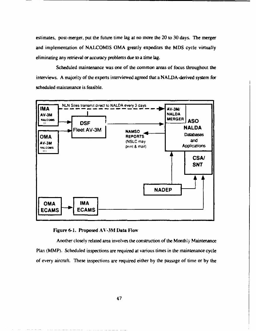
estimates, post-merger, put the future time lag at no more the 20 to 30 days. The merger
and implementation of NALCOMIS OMA greatly expedites the MDS cycle virtually
eliminating any retrieval or accuracy problems due to a time lag.
Scheduled maintenance was one of the common areas of focus throughout the
interviews. A majority of the experts interviewed agreed that a NALDA-derived system for
scheduled maintenance is feasible.
NLN Sites transmit direct to NALDA every 3 claysI--- - - - ------ -- - AV-3M1AV-3 NALDA
AV-3M MERGER ASONALDA
Fleet AV-3M NAMSO NAD
MA REPORTS' DatabasesAV-3M (NSLC may andNALCOUI print & mail) ApplicationsIIII
CSA/SNT
OMA NAIMA
ECAMEC S
Figure 6-1. Proposed A'-3M Data flow
Another closely related area involves the construction of the Monthly Maintenance
Plan (MMP). Scheduled inspections are required at various times in the maintenance cycle
of every aircraft. These inspections are required either by the passage of time or by the
47

accumulation of flight hours.3 The maintenance planner must compile these requirements
and schedule them into a systematic format to accomplish inspections as required.
Historical information can assist in planning when to accomplish a specific inspection within
the "window," or acceptable time frame, of the inspection. Once again, elapsed maintenance
time is an important variable. Using EMT the maintenance planner gains insight into how
many man hours a typical maintenance procedure may consume. When dealing with
scheduled maintenance, workloads can be prioritized to conform to available maintenance
time, i.e., per shift or work day. For example, if several aircraft require scheduled
maintenance, and there is a requirement for a large number of aircraft to be mission capable
the next day, the maintenance planner can draw EMT information from historical files to
prioritize tasks to optimize aircraft availability for the next day. In other words, perform
those scheduled maintenance tasks which provide the maximum number of "up" aircraft.
The FOJ database contains this data. Automation of some of the squadron MMP
can be performed by a DBMS on a stand-alone PC using this data at the OMA.
2. Unscheduled Maintenance
Unscheduled maintenance is a dynamic process requiring access to information,
which is as current as possible. The NALDA time lag becomes a limiting factor in this
environment. Application of data in this situation is limited to trend analysis usage. Our
interviews also revealed other information needs of the experts. To a person, a common
theme became obvious: What the maintenance controller needs most is a tool, with
instantaneous access to current data, to make the correct decisions in this dynamic
environment. The current NALDA structure cannot support this need nor was it ever
3 In most aircraft, flight hours are used to track the relative age and use of certain critical parts. Asmentioned, the F/A- 18 amraft system uses LUIs to track the life, and to determine when cetain inspectionsare required, for a number of critical parts in the PLTS program.
48

designed to. Real time computing is a necessity in the aviation maintenance environment.
The combination of NALDA database use and NALCOMIS OMA should provide the access
necessary to enable a real time or near real time environment.
3. Real Time Computing
If on-line and real time computing is available in the maintenance environment,
the maintenance manager can improve decision making capability quantifiably. The speed in
which the environment changes becomes a limiting factor. Automation can put the right
information in the right place at the right time, and speed. Unfortunately, the present
NALDA database system alone cannot support this type of real time access. To accomplish
this desired product, linkage to a MIS, like NALCOMIS, is necessary.
4. NALDA Data Use
As pointed out by McCutcheon [Ref. 23: pp. 46-48 1, NALDA data does not
enjoy wide usage in the OMA. For various reasons, whether they are unaware of data
existence or it is just used for historical data retrieval, OMA managers don't regularly use
NALDA data. The AV-3M monthly summary does receive limited use, but rarely are real-
time decisions made using this form of data.
The experts also questioned the necessity and application of NALDA data. Their
views seemed to be consistent with those found in McCutcheon's (1989) interviews.
5. NALDA Accuracy
Another area of concern expressed by the experts was the accuracy of NALDA
data. It is a widely known but little discussed fact that a squadron is graded on readiness
numbers obtained from the data submitted into the system. The AV-3M system was never
designed for this purpose. Before data is released into "the system" it is thoroughly
screened, "scrubbed," for any bit of information which could be detrimental to the
squadron's chance in competing for the various awards given on an annual basis.
49

Information is also "looked at" during inspections and is used as a grading criterion when
trying to separate the "best" squadron from the others, in some higher commands.
The accuracy of the data is therefore questionable in most maintainer's minds.
Burpo [Ref. 2: pp. 37-411 poses the question of data accuracy and concludes that a "data
fudging" occurs on a frequent basis. Burpo continues, citing several additional reasons for
the inaccuracy of NALDA data. The authors and the experts interviewed agree, from their
experience with fleet inputs, that there is a "fudge factor" used especially in the Subsystem
Capability Impact Reporting (SCIR) system.
6. What about NALCOMIS?
NALCOMIS Phase II is gaining rapid acceptance from the users interviewed.
Much of this stems from the system's capabilities to provide on-line and almost real time
computing.
NALCOMIS Phase III, or NALCOMIS OMA, can provide the on-line real time
computing needed by O-level managers. Data can be provided upline and downline from
the network with connections to supply databases and other maintenance information
databases. NALCOMIS OMA will also be the AV-3M reporting vehicle and, thus, will
contain all squadron VIDS/MAF and Naval Flight Record Subsystem (NAVFLIRS) input,
the very sources of data required by the maintenance manager.
7. User-Friendly System
Any information system that is to be introduced must be designed with the KISS4
principle in mind. This statement was echoed by all senior enlisted personnel interviewed.
There is no need to expend energy developing a system people find too complicated to
operate and, therefore, won't use!
4 KISS: Military slang for Keep It Simple, Stupid.
50

To satisfy this need, complete interaction with the user during the design phase is
essential. They alone are the people who will use and benefit from the IS.
8. Other Findings
The experts were generally in favor of a system designed to help the maintenance
program operate more smoothly. Other ideas include:" Daily schedule of events including maintenance priorities, personnel manning
requirements, non-maintenance related events, etc.* Cannibalization tracking• Part tracking through the repair system (would require link to Ilevel)• Link to the supply system part expeditor. Would provide continuous update of part
availability.* Scheduled Removal Components (SRC) scheduling. (requires real time link)• Location specific parts/equipment requirements. Would allow squadrons to obtain
information on part/equipment requirements for geographical-specificdetachments/deployments. (i.e., cold weather vs. warm weather operations)
" Phase maintenance kit tracking" Special inspection tracking (i.e., hard landings, engine over speed/over temp, etc.)" Inventory tracking. Aircraft, engine accessories, system integrity, classified
communicati,ns equipment, and other reportable equipmenL
The information presented above indicates a deep rooted interest by some fleet
experts for a better information retrieval and management system. NALCOMIS OMA will
provide the capability for many of the experts needs. No single system, one which can
accomplish all maintenance management needs, is planned for the foreseeable future.
C. SUMMARY
The intended users for ESAAMS were very direct and forthright with their comments
on the proposed system. There were three immediate uses that most could see for the
NALDA database, namely, scheduled maintenance, failure rate information and trend
analysis. While this was a common thread, it was not the primary desire for what they
really want or expect from a DBMS or expert system. On-line and real time computing are
what is desired and needed. Users want instantaneous access to current data to help
51

manage the demands of a dynamic environment. The authors agree that this is the direction
of the future. The last chapters will deal with a prototype design of an ESAAMS DBMS.
52

VII. DBMS PROTOTYPE DESIGN
A. INTRODUCTION
This chapter will discuss the design process of the ESAAMS Database Management
System. As mentioned in Chapter III, a DBMS stores, retrieves, and updates data. For the
ESAAMS DBMS, the data will come from the NALDA FOJ database which is determined
by the authors as the most useful database for an OMA maintenance manager. The FOJ
database contains a large volume of data that it can easily overload the capacity of a 200
megabyte PC hard disk drive. Henc-. the prototype database design for this thesis will only
consider data applicable to a single aviation squadron. With an evolutionary prototype
ESAAMS DBMS in mind. careful consideration into the modularity of the database design
is undertaken. Starting small with a single squadron, the prototype database design can be
expanded to a larger organization like an Air Wing or a Fleet Command. The only limitation
that the authors see right now is the micro-computer hard disk drive capacity. The data
extracted from the NALDA database tor this thesis is for VFA-25, an F/A-18 squadron
based at NAS Lemoore. CA.
Conversion from a hierarchical database model to a relational database model is needed
in order to take advantage of the powerful 4th generation language (4GL), SQL, for use by
squadron personnel. As mentioned in Chapter III, use of SQL makes ad hoc queries of the
database possible and, therefore, provides a wide range of flexibility for the maintenance
manager to manipulate the database for decision support.
The DBMS design process will cover four phases: definition, requirement, evaluation,
and design. Implementation of the prototype design, using ORACLE® RDBMS software
will not be covered in this thesis. A separate User's Manual, software application package,
53
and demonstration database will be available in April, 1992 through the thesis advisor at
Naval Postgraduate School, Monterey, CA.
B. DEFINITION PHASE
The ultimate goal of this continuing research on ESAAMS is to develop an expert
system advisor for the OMA maintenance manager. It is mentioned in Chapter I that a
knowledge base that accesses a database containing historical data, for a particular model
aircraft, is an integral part of this expert system. This database contains all domain facts that
the expert system can use. The creation of a DBMS, as a module of ESAAMS, will enable
the maintenance managers to view cata, analyze trends, print reports and perform limited
what-if decision queries.
1. Scope
Optimally, use of the entire NADA database would have been needed in order
to cover all aspects of maintenance in naval aviation and provide the maintenance manager
with the plethora of information he requires. However, the NALDA FOJ database can be
sufficient to perform scheduling, trending, and analyzing. Chapter IV covers the NALDA
databases and the contents of the FOJ database.
Extraction of data from the hierarchical NALDA FOJ database into the relational
database of ESAAMS can be performed by pulling out attributes from the FOJ schema.
These attributes are grouped together to form the entities or objects that will make the
relational database. In other words, the extracted attributes will be constructed into a flat
spreadsheet-like table, then transferred to the corresponding relational table of the
ESAAMS DBMS. Extracted data from NALDA will be in ASCII format and transferred in
batch via the floppy disk medium. The ORACLE® SQL Loader utility tool will be used for
54

the data transfer. This method of constructing the relational database from a hierarchical
database is the simplest and most feasible way of transformation without creating numerous
anomalies in the system. Current field research is still underway in the transformation of
entire hierarchical databases into relational databases [Ref. 24].
2. Feasibility
The method of extracting data from a hierarchical database by creating flat file
tables and then transforming into a relational database is feasible. The process itself is
simple but careful consideration into the design of the relational tables is paramount in order
to avoid anomalies in the resulting relational database. [Ref. 241
C. REQUIREMENTS PHASE
Potential users from VFA-25 and Senior Enlisted Personnel from
NAMTRAGRUDET, NAS Lemoore, CA were interviewed. Chapter VI contains some of
their maintenance management needs that can be fulfilled by this prototype DBMS. The
NALCOMIS OMA, when fully operational, will be a better source of data for maintenance
management because of its real time capability. With the 60 to 90 day time lag that is
inherent in the NALDA data, all potential users conclusively stated that the most probable
use for the extracted data is for historical-type knowledge. Potential applications can
include:
Historical Failure Report - this report records historical failure rate of systemsidentified by Work Unit Codes. For a selected WUC, the maintenance managercan get an idea of the failure rates of specific systems or subsystemshistorically. This is a very important application for ESAAMS. For this thesis,only the F/A-18 aircraft for VFA-25 will be covered. As the database isexpanded, other aircraft type and squadrons can be queried.
55

" Average Elapsed Maintenance Time Report - this report shows the averageelapsed maintenance times (EMT) of systems or subsystems identified by WUCfor a specific action taken (AT) code. For example, an action taken code of "R",which means remove and replace, is used when a component is removed due toa suspected malfunction and the same or like component is reinstalled. Thisgives a maintenance manager an idea of how much time to allocate for a specificmaintenance action. This information can be very valuable for ESAAMS.
" High Manhour Consumer Report - this report can aid the maintenance managerin identifying problem areas in aircraft maintenance as evidenced by manhourconsumption. This report can be queried according to aircraft Bureau Number(BUNO), aircraft system or subsystem as identified by WUC. Top manhourconsumers can be identified immediately by aircraft identification then bysystem WUCs and subsystem WUCs. Analysis of this report can showmaintenance managers of potential problems to specific aircraft orsystems/subsystems.
A very limited application can be supported by this stand-alone database because of the
time lag. Yet, for applications that are not considered dynamic, that is, not requiring real
time data. the DBMS can be used.
Figure 7-1 shows the data flow diagram of the prototype DBMS. Updating of data is
only done in batch mode on a monthly frequency, which corresponds with the update of
data in the mainframe NALDA database. Once data has been transferred from the NALDA
database to the ESAAMS relational database, applications can be generated by using the
SOL ianguage for ad-hoe queries or the programmed reports.
1. Database Objects
Five objects are designed for this prototype database. An object is a named
collection of properties that sufficiently describes an entity in the user's work environment
[Ref. 11: p. 90]. Appendix A shows the construction of these five objects. Object
diagrams summarize the knowledge of the objects and present them visually and
unambiguously [Ref. 11: p.91 ]. Appendix C contains object specifications and domain
definition for the database.
56

DatabaseCustodian
ESAAMSDATABASE
EPORT QUERY
MAINTENANCE CONTROL
Figure 7-1. Dataflow Diagram
57
a. MaintenanceAction
This object describes data which is primarily documented in the completed
VIDS/MAF. It contains attributes like elapsed maintenance time (EMT), action taken code,
wor* unit code (WUC), etc. There are a total of 18 properties in MaintenanceAction.
Fifteen are non-object properties and three are object properties. An object property is a
characteristic of the entity that is another object [Ref. 11: p. 9 1 1.
b. EndItem
EndItem contains type equipment code (TEC) as reported in record type
"A" of the VIDS/MAF, record type "7B" or record type "79." Aircraft end item and
program (parts) end items are both contained in this object. There are six End-Item
properties. four non-object and two object properties.
c. EquipmentSummary
Equipment-Summary contains availability and utilization data for
aircraft and training devices as reported on record type "79." Mission capability hours
whether FMC, PMC, or NMC per aircraft are contained in this object. Total flight hours
and number of flights are also included here. Equipment-Summary contains 14
properties with 13 non-object properties and one object property.
d. incorporated TD
IncorporatedTD contains data pertinent to an individual technical
directive incorporation as reported on record type "F" of the VIDS/MAF. Technical
Directives are always used during any maintenance evolution because they contain the latest
technical changes that must be followed before any given part or equipment is worked on
58

or operated.. There are eight properties for Incorporated_TD with seven non-object and
one object property.
e. Job-iD
JobID contains the job control number (JCN) that OMAs assign to their
maintenance action. This is used to track maintenance actions and identifies the organization
performing the maintenance. Job_ID contains six non-object properties and one object
property.
Appendix B shows the Object diagrams and Appendix C contains Object
specifications and domain definiti' ns for this database. Object diagrams summarize the
knowledge of the objects and present them visually and unambiguously [Ref. 11: p.911.
2. Methodology
The Objects formulated for this database are output-driven (i.e., derived from
intended applications). The authors' interview with domain "experts" resulted in several
applications that can be developed by the database. Although these applications are limited
in scope, as far as optimality of usage in aviation maintenance, they show that the DBMS
can be used for the ESAAMS system. Information derived from the VIDSIMAF is most
relevant for any maintenance manager, therefore, the formulation of these objects
concentrated on the data recorded from the VIDS/MAF.
D. EVALUATION
The evaluation phase of any system development consists of three tasks. First,
alternative application system architectures are identified. Second, the feasibility of the
application is reassessed now that the requirements are known in more detail and the basic
59

alternative solutions have been specified. And third, all user requirements are reevaluated
within the context of each possible solution. [Ref. 11: p. 78]
More comments on this section will be provided in the concluding chapter of this
thesis.
E. DESIGN
The design phase includes the logical database design and the applications design. A
graphical representation is presented in Appendix B.
1. Logical Database Design
a. Relationship between parent Endftem and siblings
MaintenanceAction and Equipment Summary
The EndItern, uniquely identified by TEC (Type Equipment Code) and
BUNO, may have a number of MaintenanceAction and EquipmentSummary.
End_Item has a one-to-many (I:N) optional relationship with either
MaintenanceActions and Equipment-Summary objects. TEC and BUNO are
foreign keys to both MaintenaaceAction and EquipmentSummary. JCN and WC
are the primary keys for MaintenanceAction, while BUNO and YYMM-ES are the
primary keys for EquipmentSummary.
b. Relationship between parent MaintenanceAction and sibling
IncorporatedTD
The MaintenanceAction, uniquely identified by JCN and WC, has a
one-to-one and optional relationship with Incorporated_TD. But the reverse is a
mandatory relationship. In other words, a given MaintenanceAction does not
necessarily have to have an IncorporatedTD but for each occurrence of an
60

Incorporated_TD a MaintenanceAction must be present. JCN and WC are foreign keys
to Incorporated_TD with TD_Num and JCN, as primary keys.
c Relationship between parent JobID and sibling
MaintenanceAction
MaintenanceAction and JobID are related one-to-many (I:N). A
Maintenance_Action must have (mandatory) one Job_ID but a JobID is only
optionally related to MaintenanceAction. WUC and WC are Job-lD's primary keys.
Maintenance_Action will contain WUC and WC as foreign keys.
There is no relationship between MaintenanceAction and
EquipmentSummary.
2. Application Design
The application output (i.e., reports and forms) will be developed using
ORACLE® RDBMS Version 6 software. Use of ORACLE® is necessary because
NEXPERT OBJECTS, the target expert shell software for ESAAMS development,
interacts with the ORACLES RDBMS.
User-fric, '.iness of the system is of utmost importance. To allow users to
control and direct applications, menus will be used instead of commands. An attempt to
incorporate the use of "mouse" environment will be pursued.
Menu logic and materialization will not be included in this thesis. These will be
covered fully in a separate User's Manual.
Appendix D contains prototype samples of reports desired for this DBMS as
discussed in section C of this chapter. These reports will be produced by the ESAAMS
DBMS.
61

F. SUMMARY
A DBMS is a software program that manipulates data in the database to produce results
that a user requires for his business or work. In this chapter, a walkthrough of how the
prototype ESAAMS DBMS will be designed has been covered. Numerous challenges
abound in the transformation of a hierarchical database model to a relational database
model. The planning and design of correct objects or entities and their attributes and
understanding of how the business of aviation maintenance is performed is important to the
logical presentation of the whole database.
A DBMS is only useful if it satisfies the needs of the users. This satisfaction can be
derived if the system is easy to use, the system produces the right results and it meets the
constraints that the users have in performing their business.
62

VIII. SUMMARY, CONCLUSIONS AND RECOMMENDATIONS
A. SUMMARY
To keep pace with the sophisticated and advanced technology of today's aircraft and
weapon systems, maintenance managers must have the tools, information, and data
available to make accurate, knowledgeable, and expert decisions. The management tools
and data support systems must be equally as sophisticated as the equipment they support
but designed and conistructed with a user interface which is a tQo and not a hindrance to
the process.
A wealth of data is generated daily at all levels of maintenance. This data has been
meticulously sorted and stored in various major databases throughout the Naval MDS. The
problem does not lie with the quantity of data available to the maintenance manager but, the
accessibility to this data and the transformation of this data into useful information.
Present organizational maintenance management information sysems simply do not have
the capability to provide usable data at the time and in the form required to make accurate
and timely decisions. The question presented to major project managers and the general
focus of this research is on how to get information to the manager, in a timely and usable
format, to assist in the critical decision making process. The introduction of NALCOMIS
OMA will be the first significant step to satisfying this need.
The NALDA database system contains the information necessary for decision making
but suffers from an inherent time lag of 60 to 90 days. Access to the system can only be
accomplished by on-line query or telephone requests to the user assistance group. While
both of these vehicles are productive ways to access information, they do not provide
63

sufficient focus on the OMA. However, historical failure information and elapsed
maintenance time are useful information.
The purpose of this thesis was to identify the applicable data contained in the NALDA
databases and design a user-friendly PC-based database for use with ESAAMS. A
relational database constructed from the hierarchical structure of NALDA is one answer to
providing NALDA data access to the OMA. Design, analysis and potential use of this
database concept for ESAAMS has been provided in this thesis. The authors have also
introduced the concept to the user maintenance professionals. Their opinions on aviation
maintenance community information needs substantiate the focus of this research.
The primary research questions addressed were:• What data contained in the NALDA database system are germane for use in building
the ESAAMS main database?" What uses/benefits would such a database provide an organizational maintenance
activity?
Secondary questions that evolved from the research focus were:" Are other databases in addition to NALDA required for the proper operation and
maximum benefit of ESAAMS?• What do the "experts" in the aviation maintenance community want from a
management information system?
B. CONCLUSIONS
W'hat data contained in the NALDA database system are germane for use
in building the ESAAMS main database?
The NALDA database contains voluminous amounts of data which includes
information necessary to assist the maintenance expert to make more informed decisions. It
contains all resource data entered daily on the VIDS/MAF, which is the primary source of
information required by the maintenance manager. As discussed in Chapter IV, the
NALDA FOJ database contains all the data germane for use in building the ESAAMS main
64

database. However, the time lag between a maintenance action reported at the 0-Level and
its availability for data retrieval from the NALDA system limits the utility of this database.
This research has concluded that a stand-alone database management system using only the
data contained in the NALDA database systems will have limited use and cannot support
the total maintenance decision making process required in a dynamic aviation
environment.
The NALDA system is frequently used in the IMA to track the history of parts and
assemblies throughout the maintenance/operation cycle. This level of maintenance tends to
be not as dynamic as the O-level. The problem is that the NALDA system, in its present
form, lacks real time capability.
'hat uses/benefits would such a database provide an organizational
maintenance activity?
Access to real time information is the main desire that all maintenance managers have
voiced in order to support the fast-paced evolution of aircraft mainernance. A specifically
designed. stand-alone database like the one proposed in this thesis, will provide the OMA
with a means of retrieving historical and trend data to assist the maintenance scheduling
task. In the event of any communications failure or if communications are unavailable to
the host system. this PC-based database can provide some of the needed data for decision
support. The construction of the ESAAMS database from NALDA data is an important
interim step toward accomplishment of the aviation maintenance information needs of the
future.
While the uses and benefits of a stand-alone system are limited and consume
significant time. effort, and cost to produce, the construction of this prototype database is
feasible and will achieve some benefit to the maintenance expert. This concept was
65
explored, not only to provide short term benefit to the maintenance manager, but, to
evaluate the design and project requirements for ESAAMS in the long run.
Are other databases in addition to NALDA required for the proper
operation and maximum benefit of ESAAMS?
This research has continually stressed the need for a real time capability, by any
aviation maintenance information system, to enable maintenance managers to make real
time d,-cisions. The NAVAIR 2010 Plan for total information systems (Figure 4-1 on page
24) involves the NALDAJNALCOMISINADIM interrelation. NALDA will become the
central database. This system design will enable the transmission and retrieval of real time
data to and from any potential user.
NALCOMIS Phase III becomes the central player in this schema because it provides
the necessary hardware to support the system at the OMA. Also, the NALCOMIS network
provides the necessary links and protocols. Real time data management can be achieved
using the NALCOMIS Phase III interface.
NALCOMIS OMA in its optimal form, with ESAAMS as a subsystem application,
will eliminate the inherent data time lag of the current NALDA system. Current source data
will be available locally, in addition to access to the NALDA historical files. This
combination eliminates any time lag in the retrieval and use of maintenance data. This
corresponds directly with the preferences stated by the maintenance experts interviewed.
What do the "experts" in the aviation maintenance community want
from a management information system?
Chapter VI discussed what some experts in the aviation maintenance community
wanted from a mnagement information system. They are:
" User friendliness
" Instantaneous access to data
66

" Real time computing
" Single-system architecture (like NALCOMIS)
Whatever information system is deployed for fleet use, a real time link to the aviation
maintenance data collection system should exist. To omit this feature will severely limit the
utility of the system and decision support for the maintenance manager of the future.
C. RECOMMENDATIONS
Based upon research conducted in this thesis and the conclusions offered in the
previous section, the following recommendations are offered:" Currently, OMA community knowledge of the NALDA system and its use is
limited. Every OMA should qualify a NALDA user for access to any NALDAdatabase. This could be tied to the Data Analyst schooling providing an extratwo weeks of instruction for NALDA use. This information returned to thesquadron would fill the void now present in many organizations where little, ifany. knowledge of the NALDA program exists.Presently there exists no directaccess from OMA to NALDA except through IMA facilities. The NAVAIR2010 structure which links together the NALCOMIS/NALDA/NADIM systemsshould provide access at the OMA to facilitate on-line query capability. (SeeFigure 6-1 on p. 48)
" Remove the policy of grading activities on aircraft readiness statistics which arederived from maintenance data input. This will encourage activities to reportmore accurate data and not promote "scrubbing" to improve readiness statisticsas is the current practice. The quality of data contained in the various databasesshould improve quantifiably. thus allowing a more realistic picture whenstudying trends from the databases.
" Link ECAMS and NALCOMIS OMA directly at the 0-level to eliminate processingtime and allow local use of the information on one system. The ECAMSsystem, or version thereof, is currently being implemented in several aircrafttypes. This rich source of data must be made available to the maintenancemanager on the same real time basis as NALCOMIS information. Thisimplementation would allow processing of data on a single system hardwaresuite vice the current two system setup.
* Tie-in ESAAMS as a subsystem application to NALCOMIS OMA(see Figure 8-1).The authors believe that an expert advisory system can bedesigned and made to interface with the proposed NALCOMIS OMA structure.To facilitate this linkage, the structure of the NALCOMIS/NALDA databasemust be a functional, relational database structure. Such a change in databasestructure is currently in development at NAMO. Further research into thefeasibility of such a link should be studied. This supports the originalESAAMS concept as envisioned by McCaffrey (1985).
67

SUBSYSTEMS
AMNSUBSYSTEM SUBSYSTEM
ISUBSYSTEMNACNSSUSTM
\SUBSYSTEM NACNSSUBSYSTEM
Figue 8-. NAPAS PaE L ihEA
NULXTEADNNC ASS8
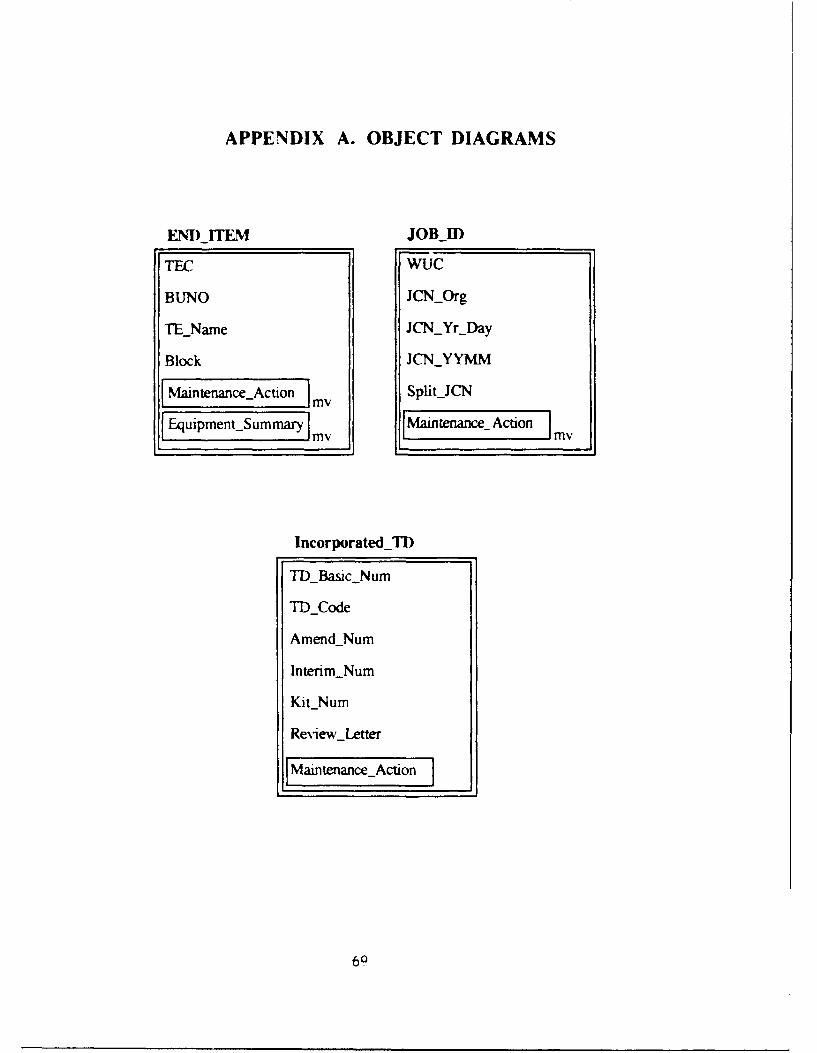
APPENDIX A. OBJECT DIAGRAMS
END ITM JOBJDl
TEA? wuc
BUNO JCNOrg
TENarne JCNYrjDay
Block JCNYYMM
Mantnn ~fo my SplitUCN
Equiprnent~ummary f2LI [ aineac dton my
IncorporatedTI)
TDBasic Num
TI)_Code
AmendNum
InterimNum
KitNum
ReviewLetter

MaintenanceAction Equipment-Summary
JCN FMCM
WC FMCS
Action_TakenCode NMCS
AWMjDays NMCM
AWP-Days, NMCU
EMT OPC
WUC PMCM
Maint-firs PMCS
MalfunctionCode Ship-Flight
Num_-Items Ship-Fight-Hrs
Recd-toComp-Days Totaljhlght-firs
Recd-toinworkDays Total-Flights
Tr-ansactionCode YYMMES
Type-..Maintenance [ndItem
WhenDiscovered
EndItem
70

APPENDIX B. ENTITY RELATION DIAGRAM
'I l
=71
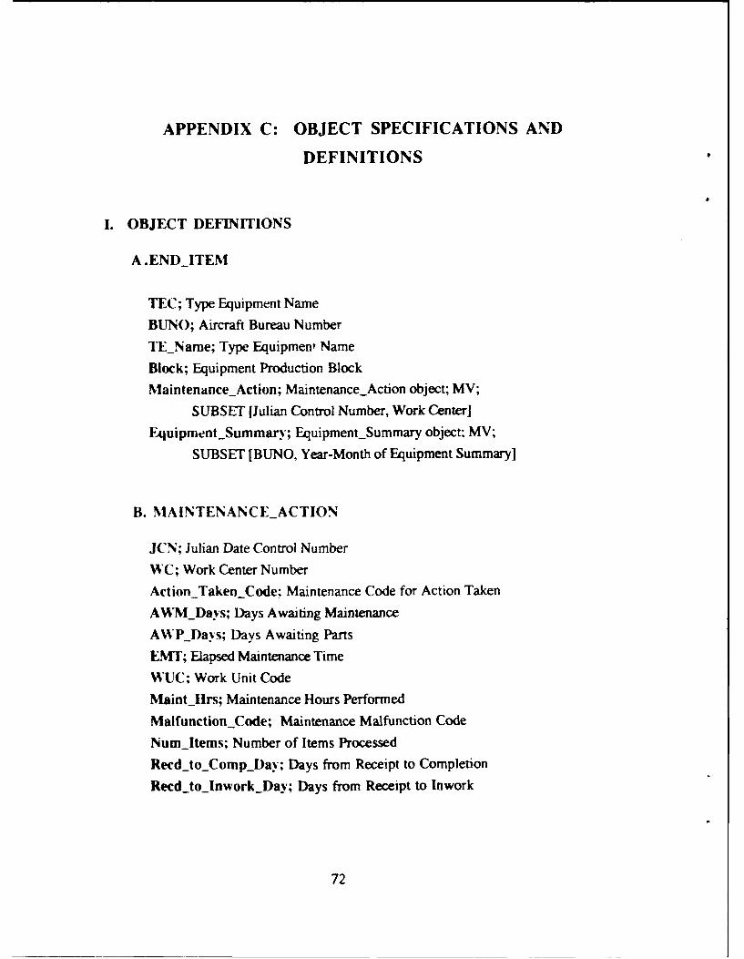
APPENDIX C: OBJECT SPECIFICATIONS AND
DEFINITIONS
I. OBJECT DEFINITIONS
A.ENDITEM
TEC; Type Equipment Name
BUNO; Aircraft Bureau Number
TEName; Type Equipment Name
Block; Equipment Production Block
MaintenanceAction; MaintenanceAction object; MV;
SUBSET [Julian Control Number, Work Center]
Equipment Summary; Equipment Summary object; MV;
SUBSET [BUNO, Year-Month of Equipment Summary]
B. MAINTENANCEACTION
JCN; Julian Date Control Number
"'C; Work Center Number
ActionTakenCode; Maintenance Code for Action Taken
AWMDays; Days Awaiting Maintenance
AWPDays; Days Awaiting Parts
EMT; Elapsed Maintenance Time
WUC; Work Unit Code
Maint-ltrs; Maintenance Hours Performed
MalfunctionCode; Maintenance Malfunction Code
NumItems; Number of Items Processed
RecdtoCompDay; Days from Receipt to Completion
Recd toInworkDay; Days from Receipt to Inwork
72

Transaction_Code; Maintenance Transaction Code
TypeMaintenance; Maintenance Type
WhenDiscovered; Maintenance Code for When
Discovered
EndItem; End_Item object; SUBSET [TEName, TEC,
BUNO]
Incorporated _TD; Incorporated.TD object; MV;
SUBSET [TDBasicNum]
Job-ED; JobID object;
C.EQUIPMENTSUMMARY
FMCM; Full Mission Capable Maintenance Hours
FMCS; Full Mission Capable Supply HoursNMCS; Not Mission Capable Supply Hours
NMCM; Not Mission Capable Maintenance HoursNMCMU; Not Mission Capable Maintenance Unscheduled
Hours
OPC; Optimum Performance Capable Hours
PMCM. Partial Mission Capable Maintenance HoursPMCS; Partial Mission Capable Supply Hours
Ship-Flight; Number of Ship Operational Flight
ShipFlight Hours; Ship Operational Flight Hours
Total-Flight; Total Number of Flights
Total_FlightHours; Total Number of Flight HoursYYMMF-S; Year and Month of Equipment Summary
EndItem; End_item object; SUBSET [BUNO, TEC,
TENamel
73

D. JOBID
WUC; Job Work Unit Code
JCNOrg; Job JCN Maintenance Organization Code
JCN_YrDay; Job JCN Year and Day
JCNYYMM; JOb JCN Year and Month
JCNSplit; Job Split Numbered JCNs
MaintenanceAction; Maintenance_Action object; MV;
SUBSET [ JCN, WC]
E. INCORPORATEDTD
TDBasicNum; Technical Directive Basic Number
TDCode; Technical Directive Code
Amend_Num; Technical Directive Amendment Number
Interim Num; Technical Directiv Interim Number
KitNum: Technical Directive Kit Number
Review_Letter; Technical Directive Review Letter
MaintenanceAction; MaintenanceAction object;
SUBSET [JCN, WC]
I. DOMAIN DEFINITIONS
A. END ITEM
1. TEC - Type Equipment Code - identifies a complete EndItem.
Text 4
2. TENAME - Type of Equipment name - identifies Type/Model/Series of
Equipment.
Text 12
3. Block - Production Block - identifier assigned by manufacturer to indicate
aircraft that have been configured identically.
Text 3
74
4. BUNO - Bureau Number - alphanumeric identifier for aircraft or equipment.
Text 6
B. EOUIPMENT SUMMARY
1. FMCM - Full Mission Capable Maintenance Hours - hours during a reporting
period that equipment is full mission capable but not optimum performance capable,
because of maintenance requirements existing on theinoperable subsystems.
Numeric 32. FMCS - Full Mission Capable Supply Hours - hours during a reporting period
that equipment is full mission capable but not optimum performance capable,
because maintenance required to clear the discrepancy cannot continue due to a
supply shortage.
Numeric 33. NMCS - Not Mission Capable Supply Hours - hours during the reporting
period that equipment is not capable of performing any of its missions because
maintenance required to clear the discrepancy could not continue due to a supply
shortage.
Numeric 3
4. NMCMS - Not Mission Capable Maintenance Scheduled Hours -hours during
reporting period that equipment is not capable of performing any of its missions
due to scheduled maintenance requirements.
Numeric 35. NMCMU - Not Mission Capable Maintenance Unscheduled Hours - hours
during reporting period that equipment is not capable of performing any of its
missions because of unscheduled maintenance requirements.
Numeric 3
6. OPC - Optimum Performance Capable Hours - hours during reporting period
that equipment is in optimum performance capability status.
Numeric 3
7. PNICM - Partial Mission Capable Maintenance Hours - hours during reporting
period that equipment is capable of performing at least one but not all of its
missions because of maintenance requirements existing on the inoperable
subsystems.
75

Numeric 3
8. PMCS - Partial Mission Capable Supply Hours - hours during reporting period
that equipment is capable of performing at least one but not all of its missions
because maintenance cannot continue due to supply shortage.
Numeric 3
9. Ship-Flight - The number of individual ship operation flights that an aircraft
has accumulated during the reporting period.
Numeric 3
10. ShipFlightHrs - Portion of the total flight hours, rounded to the nearest
whole number, accumulated on an aircraft while involved with ship operations
during the reporting period. This includes all flight hours for flights that originate,
terminate or involve a ship (i.e., a flight originates at a shore station, flies to a ship,
lands and takes off to shore), and will be reported as ship operations.
Numeric 3
11. TotalFlight.Hrs - Number of flying hours, rounded to the nearest whole
number, accumulated on an aircraft, during the reporting period.
Numeric 312. TotalFlights - Number of individual flights that an aircraft has accumulated
during the reporting period.
Numeric 3
13. YYMM_ES - Year and month for which the equipment summary record was
generated.
Numeric 4
C. INCORPORATED TD
1. TIBasicNum - Technical Directive Basic Number - number assigned by
Naval Air Technical Services Facility (NATSF) to identify the Technical Directivewhich has been approved by the Change Control Board. Numbers are assigned
sequentially from 0001 by the Technical Directive Code within the aircraft type
model.
Text 4
76

2. TDCode - Technical Directive Code - code identifying a type of Technical
Directive and system to which it is applicable.
Text 23. AmendNum - Amendment number - identifies the document that clarifies,corrects, adds to, deletes from, makes minor changes in requirements to, or cancels
an existing Technical Directive.
Text 14. Interim_Nwm - Interim Number - code indicating that the Technical Directive
is an interim change.
Text 15. KitNum - Kit Number - alphanumeric character that identifies a particular kit
associated with a particular Technical Directive.
Text 26. Review_Letter - Character that identifies the revision number of the TechnicalDirective. The character identifier is blank if the Technical Directive is not a
revision.
Text 1
D. Job ID
1. "lC - Work Unit Code - alphanumeric code that identifies the component or
end item on which maintenance was performed.
Text 72. JCNOrp Job Control Number Organization - alphanumeric code that
identifies the organization that originated the Job Control Number.
Text 33. JCN Yr Day - Job Control Number Julian Year Day - the Julian date (YYDD)that the JCN was initiated.
Numeric 5
4. JCNYYMM - Job Control Number Julian Year Month - the Julian date in year
and month (YYMM) that the JCN was initiated.
Numeric 4
77

5. SpIitJCN - Split Job Control Number - identifies multiple jobs, identifiable asseparate valid transactions which are reported with the same JCN. When multiples
occur, splitJCN is valued in each multiple job in the sequence A to Z, 0 to 9.
Text I
E. Maintenance Action
1. ActionTakenCode - code indicating action taken in performance of a
maintenance action. I.E., repair, corrosion pievention, etc.
Text 1
2. AWM_Days - Awaiting Maintenance days - total number of days a job was in
an awaiting maintenance status. Awaiting maintenance status is a summary of all
statuses having a status of 0 hrough 9 associated with a single
Numeric 4
Number of decimal 1
3. AWPDays - Awaiting Parts Days - total number of days a job was in an
awaiting parts status. Awaiting parts status is defined as a summary of all statuseswith a job status of "S" for a single maintenance action.
Numeric 4
Number of Decimal 1
4. EMT - Elapsed Maintenance Time - total elapsed clock hours for "in work"
time.
Numeric 5
Number of Decimal 1
5. ,UC - Work Unit Code -alphanumeric code that identifies the component or
end item on which maintenance was performed.
Text 76. Maint-Iours - Maintenance Manhours - total number of manhours spent
performing a maintenance action.
Numeric 5
Number of Decimal 1
7. Malfunction Code - Code describing the malfunction which necessitated the
maintenance action.
78

Numeric 3
8. NumItems - Number of Items processed - total number of items processed as
a result of the maintenance action.
Numeric 2
9. Reed_to_Comp_Day - Receipt to completion day - total number of days from
received day and time to the completion data and time.
Numeric 4
Number of Decimal I
10. Recd_toInworkDay - Receipt to In-work day - total number of days
from the received date and time to the In-work date and time.
Numeric 4
Number of Decimal 1
11. TransactionCode - code indicating the type of maintenance data reported.
I.E., on equipment work, inventory, etc.
Numeric 2
12. Type-Maintenance - Type of maintenance code - code indicating the type of
maintenance performed. I.E., scheduled maintenance, unscheduled maintenance,
etc.
Text 1
13. When _Discovered - When discovered code - code indicating when the
discrepancy was discovered. I.E., in-flight, pre-flight, etc.
Text 1
14. WC - Work Center - code identifying the work center that performed the
maintenance action.
Text 3
15. JCN - Job Control Number - the alphanumeric characters assigned to specific
maintenance requirement utilized for maintenance action tracking.
Text - 11
79

APPENDIX D. SAMPLE REPORTSIFORMS
U'I
- .. ~ C>~ M~Ito
-E-4
80

-4 4
E-44~~r~
0 C) a- 0 -4M0 40 r- 1- 4 - -
81

'0 n
in rq inq
w ~ i Cnqv r
-4 0 in 4
0 0 000Lf LO
0 0
02) -4 0n -4i ~E-4
0 '0 r-
0j 0 0
Hq~ -4 -4 in )*
E-4
0 0 1Hi
E4- 0
*0 0 C 0
H - -4 '-.) H H
V82

E~CD
020
I £4
XIoE-44
-E-
4
W Hn
83

CDp
0)o02M
E-4->)
SE4E
0
02 -
H 0
84

LIST OF REFERENCES
1. McCaffrey, Martin J.,The Feasibility of Implementing as Expert System forAircraft Maintenance with the Naval Aviation Logistics Command ManagementInformation System (NALCOMIS) Master's Thesis, Naval Postgraduate School,Monterey, CA, September 1985.
2. Burpo, John D., The Feasibility of Using the Naval Aviation Logistics DataAnalysis (NALDA) Databases for the Expert System Advisor For AircraftMaintenance (ESAAMS), Master's Thesis, Naval Postgraduate School, Monterey,CA, December 1990.
3. Chase Juhn H.Jr. A Naval Aviation Maintenance Organizational Activity StrategicInformation System (OASIS). Master's Thesis, Naval Postgraduate School,Monterey, CA, June 1990.
4. Stone, Mark, H., Development of a Knowledge Base for use in an Expert SystemAdvisor for Aircraft Maintenance Scheduling (ESAAMS), Master's Thesis, NavalPostgraduate School, Monterey, CA, March 1991.
5 Chief of Naval Operations Instruction 4790.2E, The Naval Aviation MaintenanceProgam (NAMP), Volume I, OPNAVINST 4790.2E, 1 January 1989.
6. Blanchard, Benjamin S., Logistics Engineering and Management. Prentice-HallIndustrial Series In Industrial and Systems Engineering, Prentice-Hall, Inc.,Englewood Cliffs, New Jersey. 1986.
7. Chief of Naval Operations Instruction 4790.2E, The Naval Aviation MaintenanceProgram (NAMP), Volume III, OPNAVINST 4790.2E, 1 January 1989.
8. Chief of Naval Operations, Naval Aviation Maintenance and Material ManagementManual. 1967.
9. Chief of Naval Operations Instruction 4790.2E, The Naval Aviation MaintenanceProga (NAMP), Volume H, OPNAVINST 4790.2E, 1 January 1989.
10. Chief of Naval Operations Instruction 4790.2E, The Naval Aviation MaintenanceProgm (NAM , Volume V, OPNAVINST 4790.2E, 1 January 1989.
11. Kroenke. David M. and Dolan, Kathleen A. Database Processing: Fundamentals.Design. Implementation, Macmillan Publishing Company, New York. NY, 1988.
12 Cardenas, Alfonso F., Data Base Management Systems, Allyn and Bacon, Inc.,Newton, MA, 1985.
13 Tsichritzis. Dionysios C. and Lochovsky, Frederick H., Data Base ManagementSystems, Academic Press, Inc., New York, NY, 1977.
85

14. Commanding Officer, Naval Aviation Maintenance Office, NALDA Overview andGeneral Information. Naval Aviation Maintenance Office, Patuxent River, MD, 1August 1990.
15. Naval Air Systems Command, Corporate Information Management Plan (C[MP),25 August 1990.
16. Commanding OfficerNaval Aviation Maintenance Office, AMPAS Data Sources,AMPAS Equipment Condition Analysis Book I, NALDA Users Guide, NavalAviation Maintenance Office, Patuxent River, MD, 1989.
17. Commanding OfficerNaval Aviation Maintenance Office, NALDA Usrs Manual.Section IV, Naval Aviation Maintenance Office, Patuxent River, MD, 1989.
18. Commanding OfficerNaval Aviation Maintenance Office, The NALDA DataDictiona DD-01, Volume V, Naval Aviation Maintenance Office, Patuxent RiverMD, 1989.
19. Naval Air Systems Command, Enhanced Comprehensive Asset Management
System (ECAMS) Program Guide. 1989.
20. Naval Air Systems Command, F/A-Ia ECAMS Report Users Guide. 1989.
21. Naval Air Systems Command, NALCOMIS Functional Description For theOrganizational Maintenance Activity (OMA), 1990.
22. Office of Technical Assistance, U.S. General Services Administration,NALCOMIS Benefit Analysis, 90056-02-NAVY, U.S. GSA, Washington DC,June 1991.
23. McCutcheon, David A., I1, Use of Aviation 3-M Information Outputs byOrganizational Maintenance Users. Master's Thesis, Naval Postgraduate School,Monterey, CA, December 1989.
24. Interview between Professor Magdi Kamel, Naval Postgraduate School, Monterey,CA, and the authors, October 13, 1991.
86

INITIAL DISTRIBUTION LIST
No. Copies
1. Defense Technical Information Center 2Cameron StationAlexandria, Virginia 22304-6145
2. Library, Code 0142 2Naval Postgraduate SchoolMonterey, California 93943-5100
3. Defense Logistics Studies Information Exchange IU.S. Army Logistics Management CollegeFort Lee, Virginia 23801-6043
4. Professor Martin J. McCaffrey, Code ASIMF 2Department of Administrative SciencesNaval Postgraduate SchoolMonterey, California 93943
5. Professor Balasubramanian Ramesh, Code AS/RA 1Department of Administrative SciencesNaval Postgraduate SchoolMonterey, California 93943
6. CAPT Philip Smiley 1PMA-270Naval Air Systems CommandWashington, D.C. 20361-1270
7. CAPT Donald A. Schramm ICommanding OfficerNaval Aviation Maintenance OfficePatuxent River, Maryland 20670-5446
8. LCDR Dennis K. Christensen 2Code 53Commander Naval Air Force Atlantic FleetNorfolk, Virginia 23511-5188
87

9. LT Magno 0. Pasadila. Jr. 2Operations DepartmentU.S.S. Independence CV-62FPO AP 96618-2760