Natural Method in English - A Complete Grammar - Goodloe Harper Bell - 1881 and 1915
Upload
dinhkhuongCategory
view
216download
3
NASA/CR–2010–nnnnnn
Monitoring Distributed Real-TimeSystems:A Survey and Future Directions
Alwyn GoodloeNational Institute of Aerospace, Hampton, Virginia
Lee PikeGalois, Inc., Portland, Oregon
February 2010

NASA STI Program . . . in Profile
Since its founding, NASA has been dedicatedto the advancement of aeronautics and spacescience. The NASA scientific and technicalinformation (STI) program plays a key partin helping NASA maintain this importantrole.
The NASA STI Program operates under theauspices of the Agency Chief InformationOfficer. It collects, organizes, provides forarchiving, and disseminates NASA’s STI.The NASA STI Program provides access tothe NASA Aeronautics and Space Databaseand its public interface, the NASA TechnicalReport Server, thus providing one of thelargest collection of aeronautical and spacescience STI in the world. Results arepublished in both non-NASA channels andby NASA in the NASA STI Report Series,which includes the following report types:
• TECHNICAL PUBLICATION. Reports ofcompleted research or a major significantphase of research that present the resultsof NASA programs and include extensivedata or theoretical analysis. Includescompilations of significant scientific andtechnical data and information deemed tobe of continuing reference value. NASAcounterpart of peer-reviewed formalprofessional papers, but having lessstringent limitations on manuscript lengthand extent of graphic presentations.
• TECHNICAL MEMORANDUM.Scientific and technical findings that arepreliminary or of specialized interest, e.g.,quick release reports, working papers, andbibliographies that contain minimalannotation. Does not contain extensiveanalysis.
• CONTRACTOR REPORT. Scientific andtechnical findings by NASA-sponsoredcontractors and grantees.
• CONFERENCE PUBLICATION.Collected papers from scientific andtechnical conferences, symposia, seminars,or other meetings sponsored orco-sponsored by NASA.
• SPECIAL PUBLICATION. Scientific,technical, or historical information fromNASA programs, projects, and missions,often concerned with subjects havingsubstantial public interest.
• TECHNICAL TRANSLATION. English-language translations of foreign scientificand technical material pertinent toNASA’s mission.
Specialized services also include creatingcustom thesauri, building customizeddatabases, and organizing and publishingresearch results.
For more information about the NASA STIProgram, see the following:
• Access the NASA STI program home pageat http://www.sti.nasa.gov
• E-mail your question via the Internet [email protected]
• Fax your question to the NASA STI Help Deskat 443-757-5803
• Phone the NASA STI Help Desk at443-757-5802
• Write to:NASA STI Help DeskNASA Center for AeroSpace Information7115 Standard DriveHanover, MD 21076–1320

NASA/CR–2010–nnnnnn
Monitoring Distributed Real-TimeSystems:A Survey and Future Directions
Alwyn GoodloeNational Institute of Aerospace, Hampton, Virginia
Lee PikeGalois, Inc., Portland, Oregon
National Aeronautics andSpace Administration
Langley Research CenterHampton, Virginia 23681-2199
February 2010

Acknowledgments
This work is supported by NASA Contract NNL08AD13T from the Aviation Safety Program Office. Wethank Ben Di Vito and Paul Miner of the NASA Langley Research Center, Radu Siminiceanu of theNational Institute of Aerospace, and Levent Erkok of Galois, Inc. for their comments on a draft of thisreport.
The use of trademarks or names of manufacturers in this report is for accurate reporting and does notconstitute an offical endorsement, either expressed or implied, of such products or manufacturers by theNational Aeronautics and Space Administration.
Available from:
NASA Center for AeroSpace Information7115 Standard Drive
Hanover, MD 21076-1320443-757-5802

Abstract
Runtime monitors have been proposed as a means to increase the reliability of safety-criticalsystems. In particular, this report addresses runtime monitors for distributed hard real-timesystems. This class of systems has had little attention from the monitoring community. Theneed for monitors is shown by discussing examples of avionic systems failure. We surveyrelated work in the field of runtime monitoring. Several potential monitoring architecturesfor distributed real-time systems are presented along with a discussion of how they mightbe used to monitor properties of interest.
1
Contents
1 Introduction 4
2 The Need for Monitors: Real-World Failures 62.1 Shuttle MDM Failure . . . . . . . . . . . . . . . . . . . . . . . . . . . . . . . . 62.2 Boeing 777 In-Flight Upset . . . . . . . . . . . . . . . . . . . . . . . . . . . . 72.3 A330 In-Flight Upset . . . . . . . . . . . . . . . . . . . . . . . . . . . . . . . 9
3 Preliminary Concepts 113.1 Distributed Systems . . . . . . . . . . . . . . . . . . . . . . . . . . . . . . . . 113.2 Fault-Tolerance . . . . . . . . . . . . . . . . . . . . . . . . . . . . . . . . . . . 113.3 Real-Time Systems . . . . . . . . . . . . . . . . . . . . . . . . . . . . . . . . . 12
4 Monitors: An Introduction and Brief Survey 134.1 Monitoring Distributed Systems . . . . . . . . . . . . . . . . . . . . . . . . . . 154.2 Monitoring Hard Real-Time Systems . . . . . . . . . . . . . . . . . . . . . . . 16
5 Integrated Vehicle Health Management and Monitoring 19
6 Monitor Architectures for Distributed Real-Time Systems 216.1 The “Theory” of Distributed Monitoring . . . . . . . . . . . . . . . . . . . . . 216.2 Whither the Software-Hardware Distinction? . . . . . . . . . . . . . . . . . . 226.3 Monitor Architecture Requirements . . . . . . . . . . . . . . . . . . . . . . . . 236.4 Monitor Architectures . . . . . . . . . . . . . . . . . . . . . . . . . . . . . . . 25
6.4.1 Bus-Monitor Architecture . . . . . . . . . . . . . . . . . . . . . . . . . 256.4.2 Single Process-Monitor Architecture . . . . . . . . . . . . . . . . . . . 266.4.3 Distributed Process-Monitor Architecture . . . . . . . . . . . . . . . . 27
7 Monitoring Properties: What the Watchmen Watch 287.1 Monitoring Fault-Model Violations . . . . . . . . . . . . . . . . . . . . . . . . 28
7.1.1 Monitoring Consensus . . . . . . . . . . . . . . . . . . . . . . . . . . . 297.1.2 Monitoring Timing Assumptions . . . . . . . . . . . . . . . . . . . . . 30
7.2 Point-to-Point Error-Checking Codes . . . . . . . . . . . . . . . . . . . . . . . 317.3 Monitoring Fault-Tolerant Management Software . . . . . . . . . . . . . . . . 33
7.3.1 Safety-Critical Systems . . . . . . . . . . . . . . . . . . . . . . . . . . 337.3.2 Traffic Patterns . . . . . . . . . . . . . . . . . . . . . . . . . . . . . . . 33
8 Conclusions 35
References 36
2

List of Figures
1 MDM, FA2, and GPCs . . . . . . . . . . . . . . . . . . . . . . . . . . . . . . . 72 Boeing 777 Flight Computer . . . . . . . . . . . . . . . . . . . . . . . . . . . . 73 A330 Flight Computer . . . . . . . . . . . . . . . . . . . . . . . . . . . . . . . 94 MaC Framework . . . . . . . . . . . . . . . . . . . . . . . . . . . . . . . . . . 145 A Byzantine Interpretation of a Signal . . . . . . . . . . . . . . . . . . . . . . 226 Relationship Between Behaviors Specified, Allowed, and Exhibited . . . . . . 237 A Monitor Watching a Shared Bus . . . . . . . . . . . . . . . . . . . . . . . . 258 Single Monitor on a Dedicated Bus . . . . . . . . . . . . . . . . . . . . . . . . 269 Distributed Monitors on a Dedicated Interconnect . . . . . . . . . . . . . . . 2710 Driscoll et al.’s Schrodinger CRC [1] . . . . . . . . . . . . . . . . . . . . . . . 32
3

1 Introduction
Former U.S. President Ronald Reagan’s signature phrase was the Russian proverb “Trust,but verify.” That phrase is symbolic of the political environment during the U.S.-Soviet ColdWar. For safety-critical systems, we must have a similar level of vigilance. The probability ofa catastrophic failure occurring in ultra-critical digital systems—such as flight-critical com-mercial avionics—should be no greater than one in a billion per hour of operation despite thehostile environments in which they execute [2]. To achieve this order of reliability, a systemmust be designed to be fault-tolerant. However, unanticipated environmental conditions orlogical design errors can significantly reduce a system’s hypothesized reliability.
Testing is infeasible to demonstrate that a system exhibits “1 in a billion” reliability—theessential problem is that simply too many tests must be executed [3]. Formal verification—i.e., rigorous mathematical proof—at the code level that a system exhibits ultra-reliability isalso currently impractical for industrial designs, although “light-weight” methods continueto gain traction [4].
Because neither testing nor formal verification alone is sufficient to demonstrate thereliability of ultra-reliable systems, the idea of monitoring a system at runtime has beenproposed. A monitor observes the behavior of a system and detects if it is consistent witha specification. We are particularly interested in online monitors, which check conformanceto a specification at runtime (as opposed to offline, at a later time) and can therefore drivethe system into a known good state if it is found to deviate from its specification. A monitorcan provide additional confidence at runtime that the system satisfies its specifications.
Survey Contributions As we describe in Section 4, research in monitoring has mostlyfocused on monitors for software that is neither real-time nor distributed. Only a fewstudies have addressed monitoring real-time or distributed systems, which characterizedsafety-critical systems such as flight-critical systems for aircraft and spacecraft.
The open question—and the one for which this survey lays the groundwork for answering—is whether safety-critical embedded systems can be made more reliable by online monitoring.
In summary, the contributions of this survey are as follows:
• Distributed real-time monitoring : An investigation of a class of systems that is un-derrepresented in the monitoring literature and for which monitoring may improve itsreliability.
• System-level monitoring : A focus on system-level properties, like fault-tolerance anddistributed consensus, that cannot be monitored locally but are global properties of adistributed system.
• Foundations for distributed real-time system monitoring : A set of requirements thatmonitors for real-time distributed systems must satisfy as well as three abstract ar-chitectures for monitoring (see Section 6). We also present a set of properties formonitors to address in these systems (see Section 7).
Outline A brief outline of this document follows:
• Section 2: Describes three failures of safety-critical systems, two in commercial avia-tion and one in the Space Shuttle. We intermittently reference these scenarios through-out the document to ground our discussions.
• Section 3: Presents definitions, terminology, and basic concepts on distributed systems,fault-tolerance, and real-time systems.
4

• Section 4: Surveys recent research in monitoring broadly related to our investigationof monitoring distributed real-time systems.
• Section 5: Places monitoring in context given that our investigations are particularlymotivated by safety-critical Space Shuttle and aircraft systems. In this context, mon-itoring is one aspect of an integrated vehicle health management approach to systemreliability.
• Section 6: Describes how theoretical results in distributed systems (particularly per-taining to synchrony and faults) affect the ability to monitor them. We then presentrequirements that a monitoring architecture must satisfy to be beneficial to a systemunder observation. Finally, three conceptual architectures (bus monitor, single pro-cess monitor, and distributed processes monitor) for monitoring distributed real-timesystems are presented.
• Section 7: Describes properties to be monitored in distributed real-time systems in-cluding various kinds of timing and data faults, point-to-point error detection, andfault-tolerant management software.
• Section 8: Summarizes the report and make concluding remarks.
5

2 The Need for Monitors: Real-World Failures
The design of highly-reliable systems is driven by the functionality it must deliver as well asthe faults it must survive. Three case studies are presented in which safety-critical computersystems failed. Although none of these errors resulted in the loss of life or loss of the vehicle,the problems were sufficiently severe as they could have led to such a loss if they occurred inless favorable circumstances. First, is a presentation of a case study of a fault that recentlyoccurred during the launch sequence of the shuttle orbiter. The next section covers an in-flight upset of a Boeing 777 due to a software design error. Finally, an in-flight upset of anAirbus A330 is presented.
2.1 Shuttle MDM Failure
The Space Shuttle’s data processing system has four general purpose computers (GPC) thatoperate in a redundant set. There are also twenty-three multiplexer de-multiplexer (MDM)units aboard the orbiter, sixteen of which are directly connected to the GPCs via sharedbuses. Each of these MDMs receive commands from guidance navigation and control (GNC)running on the GPC and acquires requested data from sensors attached to it, which is thensent to the GPCs. In addition to their role in multiplexing/demultiplexing data, these MDMunits perform analog/digital conversion. Data transfered between the GPC and MDMs issent in the form of serial digital data.
The GPCs execute redundancy management algorithms that include a fault detection,isolation, and recovery (FDIR) function. During the launch of shuttle flight Space Trans-portation System 124 (STS-124), there was reportedly a pre-launch failure of the faultdiagnosis software due to a “non-universal I/O error” in the Flight Aft (FA) MDM FA2located in the orbiter’s aft avionics bay [5].
According to [5, 6], the events unfolded as follows:
• A diode failed on the serial multiplexer interface adapter (SMIA) of the FA2 MDM.
• GPC 4 receives erroneous data from FA2. Each node votes and views GPC 4 asproviding faulty data. Hence GPC 4 is voted out of the redundant set.
• Three seconds later GPC 2 also receives erroneous data from FA2. In this case, GPC2 is voted out of the redundant set.
• In accordance with the Space Shuttle flight rules [7], GPC 2 and GPC 4 are powereddown.
• The built in test equipment for FA 2 was then queried (port 1 status register for MDMFA 2). This caused GPC 3 to fall out of the redundant set with GPC 1. GPC 1 wasleft to run to gather more data, but engineers terminated the launch and the problemwith FA2 was isolated and the unit replaced.
The above set of events sequentially removed good GPC nodes, but failed to detect and acton the faulty MDM. Based on the analysis reported in [6], it seems that the system doesnot tolerate single points of failure. Even though the nodes were connected to the MDM viaa shared bus, conditions arose where different nodes obtained different values from MDMFA2 (Driscoll et al., describe possible causes of Byzantine faults over a shared bus [1]). Theobserved behavior is consistent with the MDM FA2 exhibiting a Byzantine failure sendingdifferent values to the GPCs using the topology in Figure 1. The design engineers likelyassumed that since the GPCs and MDMs all communicate via a shared bus, that each GPCwould always obtain the same value from the MDM and consequently asymmetric faultswould not occur.
6

FA2
GPC1
GPC2 GPC3
GPC4
Figure 1. MDM, FA2, and GPCs
SAARU
Primary Flight Computer
ADRIU
Actuator Control Electronics
Gyro FCA
(6 Gyro FCMs)
ProcessorFCM
Accelerometer FCA
(6 Accelerometer FCMs)
Power Supply FCA
(3 Power Supply FCMs)
ProcessorFCM
ProcessorFCM
ProcessorFCM
ARINC 629 FCARight
ARINC 629 FCACentre
ARINC 629 FCALeft
Other Units
Processor FCA
ADRIU
Figure 2. Boeing 777 Flight Computer
2.2 Boeing 777 In-Flight Upset
The primary flight computer on the Boeing 777 receives inertial data from the Air DataInertial Reference Unit (ADIRU), the Secondary Altitude and Air Data Reference Unit(SAARU), and Actuator Control Electronics as depicted in Figure 2. These are all connectedto the primary flight computer via Aeronautical Radio Inc. (ARINC ) 629 units. The ADIRand SAARU both accept inputs from a variety of sources including Pitot probes—devicesused to measure air speed—and sensors indicating air temperature and aircraft angle ofattack. The data from these sources is then used in computations, the results of which arefed to the flight computers. The two units differ in their design and construction ostensiblyto provide fault-tolerance through design heterogeneity. Both units provide inertial datato the flight computer, which selects the median value of the provided data. The primaryflight computer will compute aircraft control surface position commands based on the datareceived and send commands to the actuators.
The ADIRU depicted in Figure 2 is composed of seven fault containment Areas (FCA),each of which contains several fault containment modules (FCM). For instance, the Gyro
7

FCA contains six ring-laser gyro FCMS and the Accelerometer FCA contains six accelerome-ter FCMs. The processor FCA is composed of four processor FCMs that execute redundancymanagement software that performs fault detection and isolation.
On August 1, 2005 a Boeing 777-120 operated as Malaysia Airlines Flight 124 departedPerth, Australia for Kuala Lumpur, Malaysia. Shortly after takeoff, the aircraft experiencedan in-flight upset event as it was climbing to flight level 380.1 According to [8], the eventsunfolded as follows:
• A low airspeed advisory was observed and simultaneously the slip/skid deflected tothe full right indicating the aircraft was out of trim in the yaw axis.
• The primary flight display indicated that the aircraft was simultaneously approachingoverspeed limit and the stall speed limit.
• The aircraft nose pitched up sending the aircraft climbing to flight level 410.
• The indicated speed decreased from 270 nautical miles per hour (kts) to 158kts andthe stall warning and stick shaker devices activated.
• The pilot reported he disconnected the autopilot and lowered the nose of the aircraft.
• The aircraft autothrottle then executed an increase in thrust, which the pilot coun-teracted by moving the thrust levers into idle.
• The crew was then able to use radar assistance in order to return to Perth.
Although no one was injured, the erratic information presented to the crew meant that theycould not trust the instruments that they depend upon to safely fly the aircraft. The factthat the autopilot acted on the erratic information gave additional cause for concern.
An analysis performed by the Australian Transport Safety Bureau [8] reported thatthe problem stemmed from a bug in the ADIRU software that was exposed by a series ofevents that was unlikely to have been revealed during certification testing. On June 2001,accelerometer 5 failed, but rather than failing in a fail stop manner, it continued to outputhigh voltage values. The failure is recorded in the on-board maintenance computer, but wasnot directly readable by the crew and since no in-flight warning had previously been sounded,there was no clear directive to replace the unit. The software was programmed to disregardoutput from accelerometer 5 and to use data produced by back-up accelerometers. Theaccelerometer failure was masked each time power was cycled in the ADIRU because eventhough the error was logged in the maintenance computer, the memory of this computer wasnot checked during the initialization process. Approximately one second before the upsetevent was recorded, accelerometer 6 failed. Due to a software bug, the fault-tolerant softwareused the erroneous data produced by accelerometer 5. The bug had been in previous releasesof the ADIRU software, but had been masked by other code. In the version of the softwareused in the aircraft in question, the fact that only an error in accelerometer 6 had beendetected since the unit was started meant that the software assumed there was no problemwith accelerometer 5. A detailed critique from various perspectives can be found in Johnsonand Holloway [9].
The designers clearly wanted to separate the maintenance computer’s functionality fromthe operational flight functions, but a software bug resulted in errors detected by the main-tenance computer not being transmitted to the flight systems and thus not realizing thataccelerometer 5 was faulty.
1The “flight level” is a standard nominal altitude of an aircraft in hundreds of feet calculated from theworld-wide average sea-level pressure.
8

Flight Computers
ADRIU 2 ADR 2ADRIU 3ADRIU 1 IR 2
Captain'sFlight Display
First Officer'sFlight Display
Figure 3. A330 Flight Computer
2.3 A330 In-Flight Upset
The Airbus A330 has three primary flight computers (known as PRIMs) and two secondaryflight computers. One PRIM acts as the master sending orders to the other computers. ThePRIMs are connected to three Air Data Inertial Reference Units (ADIRU). An ADIRU iscomposed of the following components:
• An air data reference (ADR) component that converts pitot and static probe data intobarometric altitude, speed, and angle of attack information, and other data.
• An inertial reference (IR) component that generates altitude, flight-path vector, trackheading, and other data. This component has two independent GPS receivers.
ADIRU 1 is connected to the captain’s flight display and ADIRU 2 is connected tothe first officer’s display and ADIRU 3 can be switched between them if necessary. Thearchitecture is illustrated in Figure 3.
The flight computers execute a set of control laws. In ‘normal law’, the computer preventsthe aircraft from exceeding a predefined safe flight envelope regardless of flight crew input.Note that many of the decisions are based on input from the ADIRUs. In an ‘alternate law’,there are either no protections offered or there are different types of protections used.
On October 7, 2008 an Airbus A330 operated as Qantas Flight QF72 from Singaporeto Perth, Australia was cruising at flight level 370 with autopilot and auto-thrust engagedwhen an in-flight upset occurred. The events unfolded as follows [10,11]:
• Autopilot disengaged and the IR 1 failure indication appeared on the Air Data InertialReference System (ADIRS) control panel.
• The flight display indicated that the aircraft was simultaneously approaching over-speed limit and the stall speed limit.
• The ADR 1 failure indication appeared on the ADIRS control panel.
• Two minutes into the incident, a high angle of attack was reported and the computersordered a significant nose-down pitch and the plane descended 650ft.
• The PRIM master changed from PRIM 1 to PRIM 2.
9

• PRIM 3 indicates a fault.
• The crew returned the aircraft to flight level 370.
• The crew switched the display from ADRIU 1 to ADRIU 3.
• The computers ordered a nose down pitch and the plane descends 400ft.
• The captain applied back pressure to the sidestick.
• PRIM master changed from PRIM 2 to PRIM 1.
• The flight control law was manually changed from ‘normal law’ to ‘alternate law’ sothat the computer was no longer enforcing predefined flight parameters.
• The crew made an emergency landing at Learmouth.
The incident resulted in injuries requiring fourteen people to be hospitalized.The preliminary investigation uncovered that ADIRU 1 failed in a manner producing
spurious spikes in data values [11]. Additional spikes in data from ADIRU 1 continuedthroughout the flight. Given that the computers were still reacting to corrupt data, itappears that the computer still accepted information from ADIRU 1 after the pilot switchedthe display to no longer show information from that unit. It was only after the pilot changedto the alternate control law did the aberrant behavior cease since the computers were nolonger using algorithms that depended on the corrupt data. Although a final report is notexpected for some time, it appears that ADIRU 1 failed while ADIRU 2 and ADIRU 3appear to have operated normally, but the system design failed to identify and isolate theproblem automatically. As long as the normal control law was engaged, the avionics systemseems to have used the spurious data from ADIRU 1. The system designers likely assumedthat such a problem would be detected and the bad unit disengaged before suffering any illeffects.
It is not clear from the literature exactly how fault tolerant the system was designed tobe without human intervention. The system was not able to recover from a single point offailure of what seems to have been a babbling device without the crew taking action. Hencethe architecture of the avionics was likely a contributing factor.
10

3 Preliminary Concepts
Having provided some motivating examples of real-world safety-critical system failures, thissection introduces some preliminary concepts and terminology used throughout the remain-der of this survey. Specifically, we introduce distributed systems, fault-tolerance, and real-time systems.
3.1 Distributed Systems
Introductory material on the foundations of distributed systems and algorithms can be foundin Lynch’s textbook [12]. A distributed system is modeled as a graph with directed edges.Vertices are called nodes or processes. Directed edges are called communication channels orchannels. If channel c points from node p to node q, then p can send messages over c to q,and q can receive messages over c from p. In this context, p is the sender or transmitter,and q is the receiver.
The only distributed systems considered in this survey are those containing a fixed setof nodes and a fixed set of interconnects between nodes. Nodes or interconnects beingintroduced or removed from the system only happens at a conceptual level, resulting fromfaults removing nodes and interconnects, or nodes and interconnects reintegrating into thesystem after suffering a transient fault [13].
3.2 Fault-Tolerance
The terms ‘failure’, ‘error’, and ‘fault’ have technical meanings in the fault-tolerance litera-ture. A failure occurs when a system is unable to provide its required functions. An erroris “that part of the system state which is liable to lead to subsequent failure,” while a faultis “the adjudged or hypothesized cause of an error” [14]. For example, a sensor may breakdue to a fault introduced by overheating. The sensor reading error may then lead to systemfailure.
In this report, we are primarily concerned with architectural-level fault-tolerance [15].A fault-tolerant system is one that continues to provide its required functionality in thepresence of faults (for the faults tolerated). A fault-tolerant system must not contain a singlepoint of failure such that if the single subsystem fails, the entire system fails. Thus, fault-tolerant systems are often implemented as distributed collections of nodes such that a faultthat affects one node or channel will not adversely affect the whole system’s functionality.
A fault-containment region (FCR) is a region in a system designed to ensure faults donot propagate to other regions [16]. The easiest way to ensure this is to physically isolateone FCR from another. However, because FCRs may need to communicate, they sharechannels. Care must be taken to ensure faults cannot propagate over these channels. Gen-erally, physical faults in separate FCRs are statistically independent, but under exceptionalcircumstances, simultaneous faults may be observed in FCRs. For example, widespreadhigh-intensity radiation may affect multiple FCRs.
Here, we characterize the faults of a node in a distributed system based on the messagesother nodes receive from it. Faults can be classified according to the hybrid fault modelof Thambidurai and Park [17]. (The same characterization could be made of channels.)First, a node that exhibits the absence of faults is non-faulty or good. A node is calledbenign or manifest if it sends only benign messages. Benign messages abstract varioussorts of misbehavior that is reliably detected by the transmitter-to-receiver fault-detectionmechanisms implemented in the system. For example, a message that suffers a few biterrors may be caught by a cyclic redundancy check. In synchronized systems, nodes thatsend messages received at unexpected times are considered to be benign, too. A node iscalled symmetric if it sends every receiver the same message, but these messages may be
11

arbitrary. A node is called asymmetric or Byzantine if it sends different messages to differentreceivers, and at least one of the messages received is not detectably faulty [18]. (Note thatthe other messages may or may not be incorrect.)
The foregoing list of faults is not exhaustive. More elaborate fault models have beendeveloped [19]. The benefit of more refined fault models is that a system designed to diagnoseless severe faults can exhibit more reliable behavior in the presence of other faults as well.For example, a six-node distributed system can only tolerate one Byzantine fault, but itcan tolerate up to one Byzantine fault and two benign faults [12]. Advanced fault-tolerantarchitectures, like NASA’s SPIDER, are carefully designed under hybrid fault model formaximal fault-tolerance for the amount of redundant hardware [20,21].
A maximum fault assumption (MFA) states the maximum kind, number, and arrivalrate of faults for each FCR under which the system is hypothesized to operate correctly. Ifthe MFA is violated, the system may behave arbitrarily. The satisfaction of the MFA itselfis established by statistical models that take into account experimental data regarding thereliability of the hardware, the environment, and other relevant factors [22]. For example,for safety-critical systems designed for commercial aircraft, statistical analysis should ensurethat the probability of their MFAs being violated is no greater than 10−9 per hour ofoperation [2]. Note that even if a system is proved to behave correctly under its MFA, butthe probability of the MFA being violated is too high, the system will not reliably serve itsintended function.
3.3 Real-Time Systems
Real-time systems are those that are subject to operational deadlines called “real-time”constraints. Consequently the correctness of such systems depends on both temporal andfunctional aspects. Real-time systems are generally classified as soft real-time systems orhard real-time systems. In soft real-time systems, missing a deadline degrades performance.For instance, dropping video frames while streaming a movie may inconvenience the viewer,but no permanent harm is done. In hard real-time systems, deadlines cannot be missed.For instance, a car engine control system is a hard-real time system since missing a deadlinemay cause the engine to fail. In such systems, deadlines must be kept even under worst-casescenarios.
12

4 Monitors: An Introduction and Brief Survey
A monitor observes the behavior of a system and detects if it is consistent with a givenspecification. The observed system may be a program, hardware, a network, or any combi-nation thereof. We refer to the monitored system as the system under observation (SUO).If the SUO is observed to violate the specification, an alert is raised. Monitoring can beapplied to nonfunctional aspects of a SUO such as performance, but historically, its focushas been on functional correctness. A variety of survey articles on monitoring have beenpublished [23–26].
Early work on software monitoring focused on off-line monitoring, where data is collectedand the analysis done off-line [27–29]. (Indeed, the term monitor was usually used todenote the act of collecting a program trace.) The focus of recent research has been onlinemonitoring, where a specification is checked against an observed execution dynamically(although online monitoring may only be used during testing, if, for example, monitoringconsumes too many additional resources). Online monitoring can be performed in-line, inwhich case the monitor is inserted into executing code as annotations. The Anna ConsistencyChecking System (Anna CCS) [30] is representative of a number of early monitor annotationsystems. In Anna CCS, a user annotates Ada programs with properties written in the Annaspecification notation and the system generates a function that acts a monitor for thisproperty. The functions are then called from the location where the annotation was placed.Recently, Java 5 [31] allows basic assertions to be inserted into programs. Online monitoringcan also be out-line, where the monitor executes as a separate process [32, 33]. Examplesof monitoring systems whose architectures combine aspects of both in-line and out-linemonitoring are presented later. Historically, the focus has been on monitoring monolithicsystems instead of distributed systems. A discussion of monitoring distributed systems isdeferred until Section 4.1.
The research challenges of online monitoring include implementing efficient monitors(assuming the monitor shares resources with the observed system) that are synthesizedfrom higher-level behavior specifications. In particular, efforts have focused on synthesizingsafety properties (informally, properties stating that “nothing bad ever happens”) fromtemporal logic specifications. Arafat, et al., have developed an algorithm for generatingefficient monitors for a timed variant of LTL [34]. Since LTL’s models are traditionallyinfinite traces [35] while a monitor typically has only a finite execution trace available,many monitoring systems use past-time linear temporal logic (PTLTL) as a specificationlanguage. PTLTL employs past-time temporal operators such as “previously” and “alwaysin the past”. PTLTL is as expressive as LTL, but more succinct than LTL [36]. Havelundand Rosu proposed a monitor synthesis algorithm for PTLTL [37] that created efficientmonitors. This work extends PTLTL, allowing one to express properties such as “functiong() is always called from within function f()” [38].
The Eagle logic [39] is an attempt to build logics that would be powerful enough to sub-sume most existing specification logics. Eagle is a first order fixed-point, linear-time tempo-ral logic with a chop operator modeling sequential composition. Although quite expressive,it does not yield efficient monitors. RuleR [40] attempts to address these inefficiencies. Amonitor is expressed in RuleR as a collection of “rules” specified in propositional temporallogic, as a state machine, or context free grammar. A trace can be efficiently checked againstthe rules using a relatively simple algorithm.
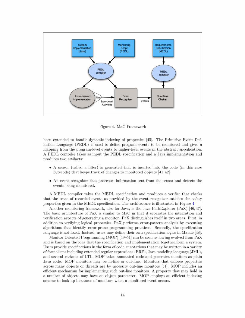
The Monitoring and Checking (MaC) toolset is a sophisticated monitoring framework [41–45]. MaC is targeted at soft real-time applications written in Java. A distinguishing featureof the MaC project is that integration and monitoring concerns are divided into separatetasks. Requirements specifications in the form of safety properties are written in the MetaEvent Definition Language (MEDL). MEDL is a propositional temporal logic of events andconditions interpreted over a trace of observations of a program execution. The logic has
13
MonitoringScript
(PEDL)
RequirementsSpecification
(MEDL)
System Implementation
(Java)
PEDLcompiler MEDL
compiler
Instrumented implementation filter Event
RecognizerRun-Time
ChekerEventsLow-LevelActivities
Figure 4. MaC Framework
been extended to handle dynamic indexing of properties [45]. The Primitive Event Def-inition Language (PEDL) is used to define program events to be monitored and gives amapping from the program-level events to higher-level events in the abstract specification.A PEDL compiler takes as input the PEDL specification and a Java implementation andproduces two artifacts:
• A sensor (called a filter) is generated that is inserted into the code (in this casebytecode) that keeps track of changes to monitored objects [41,42].
• An event recognizer that processes information sent from the sensor and detects theevents being monitored.
A MEDL compiler takes the MEDL specification and produces a verifier that checksthat the trace of recorded events as provided by the event recognizer satisfies the safetyproperties given in the MEDL specification. The architecture is illustrated in Figure 4.
Another monitoring framework, also for Java, is the Java PathExplorer (PaX) [46, 47].The basic architecture of PaX is similar to MaC in that it separates the integration andverification aspects of generating a monitor. PaX distinguishes itself in two areas. First, inaddition to verifying logical properties, PaX performs error-pattern analysis by executingalgorithms that identify error-prone programming practices. Secondly, the specificationlanguage is not fixed. Instead, users may define their own specification logics in Maude [48].
Monitor Oriented Programming (MOP) [49–51] can be seen as having evolved from PaXand is based on the idea that the specification and implementation together form a system.Users provide specifications in the form of code annotations that may be written in a varietyof formalisms including extended regular expressions (ERE), Java modeling language (JML),and several variants of LTL. MOP takes annotated code and generates monitors as plainJava code. MOP monitors may be in-line or out-line. Monitors that enforce propertiesacross many objects or threads are by necessity out-line monitors [51]. MOP includes anefficient mechanism for implementing such out-line monitors. A property that may hold ina number of objects may have an object parameter. MOP employs an efficient indexingscheme to look up instances of monitors when a monitored event occurs.
14

Much of the recent research on monitoring has focused on Java programs. A notableexception is the requirement monitoring and recovery (RMOR), which focuses on monitor-ing C programs [52]. In this work, monitors specifying both safety and bounded livenessproperties are expressed as state machines observing events recorded in a trace. In a mannersimilar to PEDL/MEDL, the monitor-refinement specification, mapping high-level eventsto program-level events, is composed with the specification for the properties to be moni-tored. RMOR takes the behavioral and the refinement specifications as well as a C programand produces a new C program augmented with code to drive the monitor. The moni-tors created by RMOR run in constant-space (i.e., no dynamic memory management) andhence are suitable for memory-constrained environments. Techniques from aspect-orientedprogramming are utilized in generating the monitors.
When a monitor detects that a property is violated, it may raise an alarm to alert theuser of a potentially catastrophic problem or take action to compensate for the problem bysteering the system into a safe mode of operation [44]. We do not specifically address thesteering problem in this report.
4.1 Monitoring Distributed Systems
Most research in runtime monitoring has focused on monolithic software as opposed to dis-tributed systems. That said, there has been some research in monitoring distributed systems;Mansouri-Samani and Sloman overview this research area (up to 1992) [53]. Bauer, et al.,describe a distributed system monitoring approach for local properties that require only atrace of the execution at the local node [54]. Each node checks that specific safety prop-erties hold and if violated, sends a report to a centralized diagnosis engine that attemptsto ascertain the source of the problem and to steer the distributed system to a safe state.The diagnosis engine, being globally situated, collects the verdict from observations of localtraces and forms a global view of the system to render a diagnosis of the source of the error.
Bhargavan, et al., [55,56] focus on monitoring distributed protocols such as TCP. Theyemploy black-box monitors that have no knowledge of the internal state of the executingsoftware. Their monitors view traffic on the network, mimic the protocol actions in responseto observed input, and compare the results to outputs observed on the network. A domainspecific language, Network Event Recognition Language (NERL), is used to specify theevents on the network that they wish to monitor and a specialized compiler generates astate machine to monitor for these events [56].
A more decentralized approach is taken by Sen, et al., which grew out of the MOPproject described above [57]. A major contribution of this work is the introduction of anepistemic temporal logic for distributed knowledge that allows the specification to referencedifferent nodes. The task of monitoring a distributed computation is distributed among thenodes performing the computation with each node monitoring properties that refer to thestate of other nodes. In order for a monitor at one node to access the state at another node,state vectors are passed around in a manner inspired by vector clocks. Since a node cannotknow the current state of another node, the epistemic logic references the last known stateof that node. When monitoring local properties, the monitors are similar to those in MOP.The communication overhead may be a concern in some application domains.
Chandra and Toueg [58] propose to extend the asynchronous model of computation (inwhich there may be unbounded delays on communication2) by adding distributed failuredetectors, which are located at each node. Each detector maintains a set of nodes it suspectsto have crashed. The detectors are unreliable in that they may erroneously add good nodesto the list of accused nodes and the list of suspects may differ at different nodes. At eachstep of computation, the failure detectors pass a list of processes currently suspected of
2The asynchronous model of computation is not generally applicable to hard real-time systems.
15
crashing. If the detectors satisfy certain conditions, the consensus problem can be solved.Several attempts have been made to extend this work [59–63]. Yet many of these attemptsonly handle what we would classify as benign faults rather than Byzantine faults. Kihlstromet al. [62] uses statistical techniques and report that they can detect Byzantine faults.
4.2 Monitoring Hard Real-Time Systems
Real-time systems are a target for monitoring since they their temporal constraints makethem hard to test and debug. Generally, research has targeted soft real-time systems (like theMaC work discussed earlier) or off-line monitoring. Early research in off-line monitoring wasto debug scheduling errors [27–29,64]. This line of research usually focused on instrumentingapplications with sensors to simply capture a time stamped trace of system calls, interrupts,context switches, and variables for the purposes of replay and analysis.
An early application of online monitoring to real-time systems focused on verifying thattiming constraints are satisfied [64]. Telecom switches have real-time constraints, and ap-proaches to monitoring these are investigated by Savor and Seviora [65]. The authors intro-duce a notation for specifying time intervals in the Specification and Description Language(SDL). Algorithms are developed for processing different interleavings of signals as well asto monitor that the specified signals occur within their designated timing intervals.
Many variants of temporal logics have been developed for specifying properties of real-time systems. A survey of these logics is given in Alur and Henzinger [66]. Recently,several efforts in the monitoring community have focused on monitoring metric temporallogic (MTL) specifications of real-time systems [67]. MTL can be used to reason aboutquantitative properties over time. For instance, one can specify the time elapsed betweentwo events.
Before discussing monitoring based on MTL specifications, some of the distinguishingfeatures of MTL are introduced. The semantics for an MTL expression is defined in termsof a timed state sequence ρ(σ, τ) composed of a finite sequence of states σ = σ1, . . . , σn anda finite sequence of real numbers τ = τ1, . . . , τn of equal length. The pair of sequences areinterpreted to read at time τi, the system is observed to be in state σi. MTL quantifiers canbe defined over intervals. Let I be one of the following:
• An interval on the non-negative reals, the left endpoint of which is a natural numberand the right endpoint of which is either a natural number or ∞.
• A congruence =d c, for integers d ≥ 2 and c ≥ 0. The expression y ∈=d c denotesy = c mod d.
The semantics for the temporal logic next operator is given as (ρ, i) |= ©Iφ iff i < | ρ |, (ρ, i+1) |= φ and τi+1 ∈ τi + I. From the definition we see (ρ |= ©[m,n] true) holds if τi+1 − τi ∈[m,n] and (ρ |= ©=dc true) holds if τi+1 = c mod d. The semantics for the until operatoris defined as ρ |= φ1 U φ2 iff (ρ, j) |= φ2 for some j ≥ i with τj ∈ τi − I and (ρ, k) |= φ1
for all i ≤ k < j. Thus φ U[4,8] ψ says that ψ holds between time units 4 and 8 andφ holds until then. The semantics for �I φ and �I φ are similarly defined. Thati andRosu [68] gave an algorithm for monitoring MTL formula and showed that even for a simplefragment of MTL, the algorithm is exponential in time and space. Drusinsky [69] uses arestricted fragment of MTL and represents MTL formulas as alternating finite automatato substantially reduce the space requirements. More recently, Basin, et al., [70] propose amonitoring algorithm using finite structures to represent infinite structures that yields anonline monitoring algorithm for a significant fragment of MTL that is polynomially boundin the size of the space consumed.
The synchronous model of computation is used in computer hardware as well as hardreal-time systems such as avionics. The synchronous paradigm follows a stream model
16

of computation. The stream values at an index are interpreted as being computed syn-chronously, and communication between streams is instantaneous. Synchronous languageslike Lustre [71,72] have been used by the embedded systems community for many years.
Although the synchronous paradigm is in common use in real-time systems, we knowof only one effort focusing on specifying monitors for synchronous systems. LOLA [73]is a specification notation and framework for defining monitors for synchronous systems.LOLA is expressive enough to specify both correctness properties and statistical measuresused to profile the systems producing input streams. A LOLA specification describes thecomputation of an output stream from a given set of input streams. A LOLA specificationis a set of equations over typed stream variables of the form:
s1 = e1(t1, . . . , tm, s1, . . . , sn)...
...sn = en(t1, . . . , tm, s1, . . . , sn)
where t1, . . . , tm is the set of input stream variables (also called independent variables)and s1, . . . , sn is the set of output stream variables (also called dependent variables) ande1, . . . , en are stream expressions over the stream variables. Stream expressions are builtfrom constants, stream variables, functions over stream expressions, boolean stream ex-pressions (if-then-else), and expressions of the form e[i, c], referring to offset i of streamexpressions e, where c is a constant that acts as the default if the offset lands before thebeginning of the stream or after the end of the stream. Four examples follow:
s1 = t1 ∨ t2 ≤ 1s2 = ((t2)2 + 7) mod 15s3 = ite(s1, s2, s2 + 1)s4 = t1[+1, false]
Stream equations “lift” operators to the stream level, so s1 says that at position i of thestream, t1(i)∨ t2(i) ≤ 1, where t1 is a stream of binary values and t2 is a stream of integers.The next specification simply takes the integer stream t2 and computes a new integer. Thesteam expression defining s3 references the previous two expressions as inputs. If s1(i) istrue, then s3(i) takes on the value s2(i), otherwise it takes the value s2(i) + 1. The finalexample illustrates the offset operator. Here, each position i of stream s4 corresponds to thevalues at position i+ 1 of the input stream t1 and to false if i+ 1 is beyond the current endof the t1 stream. The authors present a monitoring algorithm for converting the equationalLOLA specifications into efficient executable monitors.
Mok and Liu developed the language Real-Time Logic (RTL) for expressing real-timeproperties for monitoring. A timing constraint specifies the minimum/maximum separationbetween a pair of events. A deadline constraint on an event E1 and an event E2 is violatedif the event E2 does not occur within the specified interval after event E1. Given an event eand a natural number i, the occurrence time of the i-th instance of e is denoted as @(e, i).Timing constraints in RTL often take the following form:
@(a, i) + 20 ≥ @(b, i) ≥ @(a, i) + 5@(b, i) + 10 ≥ @(c, i) ≥ @(b, i) + 2
which says that event b should not happen earlier than five time units after event a and nolater than twenty time units after event a and that event c must not happen earlier thantwo time units after b or later than ten time units after b. To monitor RTL constraints,Mok et al. employ sensors that send timestamped events to the monitor, and an algorithmcomputes the satisfiability of the constraint [74,75].
17

Any runtime monitoring of hard real-time systems cannot interfere with the executionof the application and particularly its timing constraints. Consequently, out-line monitors(i.e., monitors executing as a separate process from the one being monitored) are preferred.Pellizzoni et al. [32, 33] have constructed monitors in FPGAs to verify properties of a PCIbus. The monitors observe data transfers on the bus and can verify if safety properties aresatisfied.
18

5 Integrated Vehicle Health Management and Monitor-ing
This section places monitoring within the context of the larger goals of an integrated vehiclehealth management (IVHM) approach to system reliability. As overviewed by Ofsthun,IVHM is a program to increase the accuracy, adaptability, and management of subsystemsin automobiles, aircraft, and space vehicles [76]. The goals of IVHM are to increase safetywhile decreasing maintenance costs (for example, by reducing false positives in built-intesting). IVHM broadly applies to the subsystems of a vehicle including propulsion systems,actuators, electrical systems, structural integrity, communication systems, and the focushere, avionics. Ofsthun notes that recent advances in IVHM add prognostics (i.e., predictivediagnostics), which allow systems to determine the life or time span of proper operation of acomponent. In the case of components that tend to degrade due to wear and tear, predictivesystems identify degraded performance and identify when preventive maintenance is needed.
IVHM research in aviation and space systems has typically focused on physical compo-nents such as actuators [77], engine components, and structures. Recent advances in sensors,signal processing, and computing allow accurate measurements of such components to be de-termined in real-time. Advances in engineering science have yielded improved models of thephysical aircraft itself. IVHM systems monitor the physical system and compare it againstthe mathematical model of the physical system. As noted by a National Research Councilreport, this allows the “aircraft to trace back the system anomalies through a multitude ofdiscrete state and mode changes to isolate aberrant behavior” [78]. These diagnostics allowthe aircraft to detect unseen cracks in moving parts. Such systems can lower maintenancecosts as well as improve safety.
Such IVHM measures make sense for systems that degrade over time, like materials orhardware. But software does not degrade over time, so it should be reliable on its firstuse, and it should remain reliable over time. Evidence for the reliability of critical softwarecomes principally in one of three forms: certification, testing, and verification.
The Federal Aviation Authority (FAA) codifies high-assurance software developmentprocesses in standards such as DO-178B [79]. Currently, these standards rely heavily on acombination of rigorously-documented development processes and software testing. Whilecertification provides evidence that good practices are followed in software development, itdoes not guarantee correctness. Recall from Section 2.2 the incident involving a MalaysianAir Boeing 777 where a software problem was undetected during DO-178B certification.Although we were not able to determine if the system was subject to level A certification,it nevertheless is disconcerting that the problem went undetected in certification. More orbetter testing is not a feasible solution for demonstrating reliability, at least for ultra-criticalreal-time software [3]. Consequently, The National Academies advocate the use of formalmethods to augment testing using mathematical proof [80].
However, such proofs are not over the realizations themselves but over models of therealizations and the complete verification of a complex implementation remains elusive. As-suming that formal methods are applied to an abstraction of the system, some verificationthat the implementation complies to the specification is needed, especially when the speci-fication has built-in assumptions about the implementation. Of course, as a model’s fidelityto an implementation increases, so does the cost of formal verification.
Because of the respective disadvantages of certification, testing, and formal methods, afourth form of evidence is being explored: the idea of runtime monitoring. Runtime moni-toring can be seen as an aspect of IVHM [81–83] that can potentially detect, diagnose, andcorrect faults at runtime. Indeed, Rushby argues that runtime monitoring can be consideredas a form of “runtime certification” [81, 82]. As Rushby notes, one motivation for runtimecertification is that one source of software errors is a runtime violation of the assumptions
19

under which the software is designed (and certified). Runtime monitoring frameworks canrefine formal specifications of requirements into software monitors. Furthermore, Rushbyargues that monitors have the greatest potential payoff in monitoring system-level propertiesrather than unit-level requirements, which DO-178B practices catch well.
20

6 Monitor Architectures for Distributed Real-Time Sys-tems
In this section, we explore various abstract monitoring architectures for fault-tolerant real-time systems, focusing on their tradeoffs. First, some theoretical aspects of monitoringdistributed systems which frame our discussion are presented. Next, requirements relatingto functionality, schedulability, and reliability relating to monitor architectures are consid-ered. Finally, we present and compare three abstract monitor architectures for distributedsystems.
6.1 The “Theory” of Distributed Monitoring
Recall that this paper examines the applicability of runtime monitoring to real-time dis-tributed systems. Consequently, we wish to understand the limits of the ability of monitorsto detect faults in these systems. While it may seem that monitoring distributed real-timesystems requires a new theory, we argue that it does not. Rather, theoretical results indistributed systems subsume monitoring.
Our reasoning is based on the following uncontroversial thesis we propose:
Distributed-System Monitoring Thesis: Monitors for a distributed system areother processes in the distributed system.
The thesis implies that there is no omniscient view of a distributed system. A monitor,whether it be a user or a process, somehow gathers information from the other processes ina distributed system, just like those other processes gather information from each other fordistributed computation. A monitor may be privileged—for example, it might have a moreaccurate physical clock or it might have communication channels from every other node inthe system—but these are differences of degree and not of kind: in principle, other processescould be augmented with more accurate clocks or more channels.
Some consequences follow from the thesis. The first consequence we have already men-tioned: Any theoretical result on distributed systems applies to distributed-system monitors.The theory of distributed systems is well-developed, and has established fundamental limitson synchronization, fault-tolerance, fault-detection, and observation [12, 84, 85]. Any theo-retical limitation on distributed systems applies to a distributed-system monitor. Therefore,let us review known theoretical limitations and consequences for monitoring distributed sys-tems regarding synchronization and faults.
Synchronization and faults make distributed computing complex. Let us ignore theproblem of faults for a moment and focus on synchronization. If a distributed system cansynchronize, then computation can be abstracted as a state machine in which individualprocessors act in lock-step. Mechanisms have been developed to ensure that individualnodes agree on time, at two levels of abstraction [84, 85]. Simply agreeing on the orderof events in the system is called logical clock synchronization. If processes must agreeon the real time (or “wall-clock time”) that events occurred at, then processes maintainand synchronize physical clocks. (Physical clocks can be implemented, for example, usingcrystal-controlled clocks common in digital hardware devices.)
The presence of faults complicates matters. A monitor detects faults in the systemunder observation (SUO). However, the monitor itself may suffer faults, and if it does, itmay incorrectly attribute the fault to the SUO or take some other unanticipated action. Amonitor must therefore be shown not to degrade the reliability of the SUO. For example, amonitor should be demonstrated not to become a “babbling monitor,” continuously signalingan error even if there are no faults in the SUO. We expand on this issue in Section 6.3.
21

time
d
cp(T) cq(T)
signal
signal strength
Figure 5. A Byzantine Interpretation of a Signal
But anomalous behavior is possible even if no process in the distributed system—including the monitor—is faulty. In particular, consider a distributed system which main-tains synchronized clocks (as is the case in ultra-reliable fault-tolerant architectures [16]).Synchronized physical clocks do not maintain perfect synchrony. Because of the inherent im-precision of physical clocks, they can only be kept synchronized within some small real-timevalue d. The inherent asynchrony results in the potential for Byzantine behavior, which oc-curs when a single process appears to broadcast two different signals to two recipients [1,18].As an example, consider Figure 5, which depicts two processes, p and q. For p, the functioncp(T ) takes a discrete clock time T from its own clock and returns the earliest real timewhen it reaches that clock time, and similarly for q. Note that these real times fall within dof each other, so we consider them to be synchronized. Suppose further they both monitorthe same signal on a wire. For the signal to register with a process, it must be above somethreshold. In the figure, p does not detect the signal while q does. Thus, q accuses theprocess transmitting the signal of being faulty while p does not, even though they are bothsynchronized.
As Fidge notes [85], such behaviors introduce nondeterminism: the same trace of actionsby individual processes may lead to different global behaviors. Consequently, if a monitorobserves violations of a property, and that property depends on some observable eventmeeting a real-time deadline, then the monitor will return both false positives and falsenegatives. Within some delta of real-time, it is indeterminate whether the property issatisfied.
6.2 Whither the Software-Hardware Distinction?
Monitoring approaches generally fall into ones for hardware and ones for software. Theapproaches we have surveyed in Section 4 primarily focus on software. However, for fault-tolerant real-time systems, the distinction is less useful from both the real-time and fault-tolerance aspects.
First, real-time guarantees are dependent upon the behavior of both software and hard-ware. Attempting to decompose a monitor to observe just the real-time behavior of thesoftware or hardware in isolation is not practical (and perhaps not even feasible). Rather,if a monitor detects a missed deadline, a probabilistic analysis can be used to determinewhether the failure is due to a systematic (i.e., software) fault or a random (i.e., hardware)fault. For example, if the deadline is missed by a large margin, then a logic error might beconsidered to be more probable than a random hardware fault. A similar conclusion mightbe reached if deadlines are missed too often. (Also see Section 7.1.2 for a more detaileddiscussion of these issues.)
Like real-time behavior, faults originate in either software or hardware and cannot gen-
22

Specifiedbehaviors
Behaviorsexhibited by
SUO
Behaviorsallowed by monitor
Figure 6. Relationship Between Behaviors Specified, Allowed, and Exhibited
erally be distinguished on the basis of a single observation. Rather, probabilistic methodscan be used, based on knowledge of the environment and of the failure rate of the hardware.
6.3 Monitor Architecture Requirements
A monitor architecture is the integration of one or more monitors with the system underobservation (SUO). The architecture includes all the additional hardware and interconnectsrequired to carry out the monitoring. Monitoring fault-tolerant real-time systems placesspecial constraints on potential architecture. We propose the following to be architecturalconstraints that must be met:
1. Functionality : the monitor does not change the functionality of the SUO unless theSUO violates its specification.
2. Schedulability : the monitor architecture does not cause the SUO to violate its hardreal-time guarantees, unless the SUO violates its specification.
3. Reliability : the reliability of the SUO in the context of the monitor architecture isgreater or equal to the reliability of the SUO alone.
4. Certifiability : the monitor architecture does not unduly require modifications to thesource code or object code of the SUO.
If these criteria are met, we say that the monitor benefits the SUO. The functionality require-ment is characteristic of monitoring systems and simply ensures that the monitor behaveslike a monitor and does not modify the nominal functionality of the SUO. However, themonitor may modify the behavior of the SUO if the SUO is detected to violate its specifi-cation. We diagram this relationship in Figure 6; any portion of the behaviors exhibited bythe SUO that are not allowed by the monitor may be modified by the monitor.
The schedulability requirement ensures that the monitor does not interfere with thetimeliness of the services provided by the SUO. Timeliness violations can occur both due toadditional constraints on the processes and the channels between processes that monitoringplaces upon the system. For example, software in the processes might be instrumentedwith additional code for monitoring purposes, which can affect the timeliness of services.Likewise, distributed monitors that communicate over the same channels that are used bythe SUO can decrease the bandwidth available for the messages of the SUO.
23

When a monitor detects a runtime error, it may steer the SUO into a good state (althoughin general, steering is a separate concern from monitoring). The schedulability requirementshould not be taken to imply that the SUO’s schedule cannot be disrupted or modifiedduring the steering phase.
The reliability criterion is somewhat subtle. The requirement is intuitive insofar as amonitor architecture should not decrease the reliability of the SUO. However, note that itis allowable for the reliability of the SUO in the context of the monitor architecture to beequal to the reliability of the SUO alone. For example, if the monitor only collects datafor off-line analysis, then the monitor’s reliability should not adversely affect the reliabilityof the SUO—even if the monitor is quite unreliable. Furthermore, this criterion does notmandate that faults in the monitor architecture must not propagate to a failure in theSUO. That is, suppose the reliability of a system S is 1 − 10−X per hour of operation.Now suppose that S is composed with a monitor M, resulting in S ∪M. Suppose in thecomposition, the monitor takes no corrective action, but faults from M can propagate toS, and that the reliability of the composition is 1 − 10−Y per hour, where Y < X; thatis, the composition is less reliable than S alone. Now suppose that in the composition,the monitor does take corrective action if faults are detected in S, and suppose that underthis scenario, the reliability of the composition is 1 − 10−Z per hour, where Z > X. Thenthe reliability criterion is satisfied, even though faults can propagate to the SUO from themonitor. Additionally, an implementation might refine the property to show, for example,that the monitor degrades gracefully in the presence of faults.
When we speak of the reliability of the SUO, we must keep in mind the difference betweenits nominal reliability, in which we suppose the only source of faults are environment-inducedhardware failures, and its actual reliability, which takes into account both hardware failuresas well as systematic design errors (in either hardware or software). Design errors maydramatically reduce the reliability of an ultra-reliable system [3]. If it is hypothesized thatthe reliability of the SUO is below its required reliability due to unknown design errors, thenit may be quite easy for a monitor architecture to satisfy the reliability requirement. Indeed,each scenario described in the case-studies presented in Section 2 resulted from systematicerrors rather than environment-induced random errors.
Finally, we propose the constraint of certifiability. If an SUO is intended to be evaluatedunder a safety-critical certification standard (e.g., DO-178B [79]), introducing a monitorshould not make a re-evaluation of the SUO in the context of the monitor overly difficult.If the monitor satisfies the functionality, schedulability, and reliability constraints, then acertified SUO should be certifiable in the context of the monitor, but those constraints donot address the kind and level of evidence required to demonstrate that they are satisfied.An evaluation intended to provide this evidence could range from simply composing theindependent evaluations of the SUO and the monitor to requiring a complete re-evaluation ofthe SUO in the context of the monitor. In practice, the evidence required will fall somewherewithin that range: the certifiability constraint is one of degree. An “upper bound” is thatadding a monitor would require fully repeating the verification and validation of the SUOin the context of the monitor.
We postulate that a monitor framework that requires rewriting or modifying the sourcecode or object code of the SUO—like most monitoring frameworks do—generally makes re-evaluation too onerous, since it likely requires full re-evaluation of the SUO. Therefore, theconstraint of certifiability is taken to mean that the monitor does not introduce “significant”source (or object) code modifications to the SUO.
A proven means to ease the difficulty of demonstrating that one software system does notinappropriately interact with another is to make the argument at the hardware-architecturelevel. For example, time-triggered architectures make this guarantee in the temporal dimen-sion [21,86]. The monitoring architectures described in Section 6.4 are intended to describethe hardware-architecture level approaches to monitoring distributed systems.
24

xn
Data Bus Interconnect
x0
Monitor MonitoringArchitecture
SystemUnderObservation
Figure 7. A Monitor Watching a Shared Bus
Finally, Rushby recently argues that runtime monitoring can provide a framework forruntime certification, in which some evidence of correctness is deferred to runtime [81]when monitors collect the evidence. The novel notion of runtime certification depends on aconstraint like the certifiability constraint to hold as well as the monitors themselves beingfault-free [87].
6.4 Monitor Architectures
We propose three abstract monitor architectures and discuss them in the context of therequirements stated above. We keep our presentation at a conceptual level given that we areprimarily proposing architectures that may investigated in future research. In the figures, weshow a distributed SUO and an associated monitoring architecture. The SUO architectureis made up of a set of distributed processes x0, x1, . . ., xn together with an interconnect. Werepresent the interconnect abstractly. For example, the interconnect could be a simple serialbus, or it could be a graph of interconnects, such as a ring or star, between processes [16].Recall from Section 3.1 that we are considering monitors for distributed systems containinga fixed set of nodes and a fixed set of interconnects between nodes that are modified onlyby faults in the systems.
Our presentation begins with the simplest architecture employing a single monitor andrequiring no additional hardware, and proceeds in order of increasing complexity.
6.4.1 Bus-Monitor Architecture
The first architecture under consideration is depicted in Figure 7, where the monitor Mobserves traffic on the data bus of the SUO. In this architecture, the monitor receivesmessages over the bus just like any other process in the system. However, the monitor wouldlikely be a silent participant that does additional error checks on in-bound messages or verifythat protocol communication patterns are being followed. Only if it detects a catastrophicfault would it send messages to the other processes through the bus. As discussed in 4.2,BusMoP [32,33] adapts this very architecture to verify bus protocols. In the case of BusMoP,the monitor is implemented in an FPGA that is interposed between the peripheral hardwareand the bus allowing it to sniff all activities on the bus. Bhargavan et al. similarly monitoractivity over the wire to capture TCP packets [55,56].
As compared to the other architectures being considered, the bus-monitor architecturerequires the least additional hardware for monitoring. It is arguably the simplest monitor-ing architecture, although it must be ensured that the monitor does not become faulty and
25
xn
Data Bus Interconnect
x0
Monitor
Monitor BusMonitorArchitecture
SystemUnderObservation
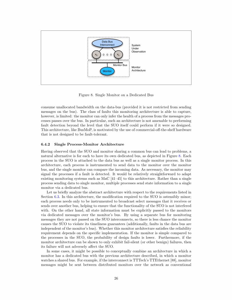
Figure 8. Single Monitor on a Dedicated Bus
consume unallocated bandwidth on the data-bus (provided it is not restricted from sendingmessages on the bus). The class of faults this monitoring architecture is able to capture,however, is limited: the monitor can only infer the health of a process from the messages pro-cesses passes over the bus. In particular, such an architecture is not amenable to performingfault detection beyond the level that the SUO itself could perform if it were so designed.This architecture, like BusMoP, is motivated by the use of commercial-off-the-shelf hardwarethat is not designed to be fault-tolerant.
6.4.2 Single Process-Monitor Architecture
Having observed that the SUO and monitor sharing a common bus can lead to problems, anatural alternative is for each to have its own dedicated bus, as depicted in Figure 8. Eachprocess in the SUO is attached to the data bus as well as a single monitor process. In thisarchitecture, each process is instrumented to send data to the monitor over the monitorbus, and the single monitor can compare the incoming data. As necessary, the monitor maysignal the processes if a fault is detected. It would be relatively straightforward to adaptexisting monitoring systems such as MaC [41–45] to this architecture. Rather than a singleprocess sending data to single monitor, multiple processes send state information to a singlemonitor via a dedicated bus.
Let us briefly analyze the abstract architecture with respect to the requirements listed inSection 6.3. In this architecture, the modification required to the SUO is ostensibly minor;each process needs only to be instrumented to broadcast select messages that it receives orsends over another bus, helping to ensure that the functionality of the SUO is not interferedwith. On the other hand, all state information must be explicitly passed to the monitorsvia dedicated messages over the monitor’s bus. By using a separate bus for monitoringmessages they are not passed on the SUO interconnects, so there is less chance the monitorcauses the SUO to violate its timeliness guarantees (additionally, faults in the data bus areindependent of the monitor’s bus). Whether this monitor architecture satisfies the reliabilityrequirement depends on the specific implementation. If the monitor is simple compared tothe processes in the SUO, the probability of design faults is lower. Furthermore, if themonitor architecture can be shown to only exhibit fail-silent (or other benign) failures, thenits failure will not adversely affect the SUO.
In some cases, it might be possible to conceptually combine an architecture in which amonitor has a dedicated bus with the previous architecture described, in which a monitorwatches a shared bus. For example, if the interconnect is TTTech’s TTEthernet [88], monitormessages might be sent between distributed monitors over the network as conventional
26

xn
Data Bus Interconnect
x0
M0 Mn
Monitor Bus Interconnect
MonitoringArchitecture
SystemUnderObservation
Figure 9. Distributed Monitors on a Dedicated Interconnect
Ethernet traffic, which is guaranteed by the TTEthernet not to interfere with safety-criticalmessages sent over the same network.
6.4.3 Distributed Process-Monitor Architecture
We show an architecture in Figure 9 where there are distributed monitors M0, M1, . . ., Mn
corresponding to each process x0, x1, . . ., xn in the SUO. MonitorMi may be implemented onthe same hardware as process xi, or it could be in its own fault-containment unit; the formeris cheaper (in terms of hardware resources), but the latter provides less chance of a monitorfailing due to the same fault as its associated process. Note that the monitor’s interconnectmay be fault-tolerant even if the SUO’s interconnect is not. Thus, you can “clamp on”fault tolerance. In this architecture, online distributive monitors need to communicate witheach other in order to reach agreement on diagnoses. Thus, we abstractly represent someinterconnect between the monitors. This is similar to the architectures implemented in [57]and [54], but in those cases the SUO and the monitors use a shared bus, which given thetraffic between monitors may compromise hard real-time deadlines.
As compared to the single process-monitor architecture in Figure 8, this architecture hasthe advantage that it supports a potentially more reliable monitor since the monitors aredistributed. So even if one or more Mi’s fail, the monitor may assist the system.
A distributed monitor also has an additional benefit in that an individual monitor Mi
can serve as a guardian to its corresponding process xi. In the single process-monitorarchitecture, a “babbling” process could prevent other processes from sending messages tothe monitor or prevent the monitor from signaling the processes in the case of a detectederror.
On the other hand, a distributed monitor is more complicated, and that complexitymay lead to less reliability in the monitor. Furthermore, the distributed process-monitorarchitecture may be nearly as expensive in terms of processes and interconnects as the SUOitself. A distributed architecture may not be feasible if the monitor has stringent cost, size,weight, or energy consumption constraints.
27

7 Monitoring Properties: What the Watchmen Watch
Thus far, we have discussed fault-tolerant distributed systems, monitoring in general, andpotential monitor architectures. Our discussion leaves open the question of what to monitorin fault-tolerant real-time systems. Here, we attempt to classify relevant general propertiesand describe potential approaches to monitoring these classes of systems.
Again, we remind the reader that fault-tolerant real-time systems used in safety-criticalcontexts are typically engineered according to best-practices and are extensively tested.Thus, the kinds of properties we describe in this section are often taken into account inthe architectural design. That said, we have seen in Section 2 cases in which deployedsafety-critical systems have failed due to incorrect designs or architectures that make invalidassumptions about the environment. These systems are good candidates for monitoring.
In general, monitors can observe arbitrary safety properties in distributed real-timesystems, up to the limits described in Section 6.1 and by Fidge [85]. Informally, safetyproperties state that “something bad does not happen.” This is opposed to liveness prop-erties, stating that “something good eventually happens” [89]. Liveness properties includeimportant properties (e.g., program termination), but in general, they cannot be monitoredat runtime—intuitively, this is because there is no bound on when to declare the propertyto be falsified. However, as Rushby notes for real-time systems, all properties are effectivelysafety properties, since showing that “φ eventually happens by a finite deadline” is equiva-lent to showing that “not φ does not happen by the deadline” [81]. The classes of propertieswe describe in this section are safety properties.
This section is organized as follows. First, we consider using online monitoring tostrengthen the fault model under which a system was originally designed—in particular,for tolerating Byzantine faults a system was not originally designed to tolerate. Onlinemonitoring to strengthen point-to-point error detection (e.g., cyclic redundancy checks)is then considered. Finally, we consider its use to check the correctness of software thatmanages fault-tolerance in a system.
For each class of properties, we consider the applicability of the architectures we haveproposed in Section 6.
7.1 Monitoring Fault-Model Violations
Fault-tolerant systems are designed to withstand a particular maximum fault assumption(MFA)—recall the review of fault-tolerance concepts from Section 3.1. A designer’s formu-lation of a system’s MFA is based on a variety of factors including knowledge about theoperational environment, reliability of the individual components, expected duration a sys-tem is to be fielded, number of fielded systems, cost, and so on. Many of these factors areunder-specified at design time (for example, systems are used well beyond their expectedretirement dates or for unanticipated functionality). Because the MFA is chosen based onincomplete data, it may be inappropriate, and in particular, too weak. Furthermore, asystem’s MFA is built on the assumption that there are no systematic software faults, butsoftware faults can dramatically reduce the hypothesized reliability of a system [3].
In a fault-tolerant system, the relationship between software and hardware is subtle.We can characterize two kinds of software in such a system: the software that implementsa system’s services, and the software that manages the system’s response to faults. Thebehaviors of fault-management software are determined by the presence of random hardwarefailures caused by the environment—indeed, the software can be thought of as a reactivesystem responding to faults. Thus, to know at runtime whether fault-management softwareis behaving correctly, one must also know the status of the hardware failures in the system.So it would seem that for a monitor to determine the health of the fault-managementsoftware, it must know which hardware faults are present. But detecting hardware faults is
28

precisely the job of the fault-management software itself!In Section 2, we saw concrete examples of system failures that were the result of an
insufficient MFA (i.e., unexpected faults). As mentioned before, Byzantine or asymmetricfaults are particularly nefarious and often unanticipated. Consider the case of the abortedspace shuttle launch described in Section 2.1. The failure of a single diode produced asym-metric faults that the system design failed to anticipate. It appears that the system wasdesigned to satisfy a MFA that did not accommodate asymmetric faults. It is conceivable(we are speculating here) that designers chose a fault-model that excludes asymmetric faultsbecause the designers judged that the probability of their occurrence to be so small thatthe additional complexity required in a system design intended to detect and mask suchevents was unwarranted. Indeed, in some cases, designs that handle rare faults can increasethe probability that less rare faults do occur [90]. The intuition is that fault-tolerance re-quires redundancy, and redundancy means more hardware. The more hardware there is,the more likely some component in the system will fail.3 However, it has also been arguedthat Byzantine faults, while rare, are much more probable than generally believed [1].
The fundamental property that establishes the absence of a Byzantine fault is a consensusproperty [18]. Consensus tells us that each receiver of a broadcasted message obtains thesame value. If we presume that a system is not designed to tolerate Byzantine faults at theoutset to ensure a consensus property holds, we are inclined to monitor consensus propertiesat runtime.
Below, we consider the use of the monitoring architectures we have described both toensure consensus of distributed values and then to ensure timing assumptions made by thesystem are met.
7.1.1 Monitoring Consensus
To monitor consensus at runtime, the values receivers obtain must be compared. Con-sider exact agreement, where each receiver should obtain the exact same value, rather thanapproximate agreement, where each receiver should obtain data that agrees within somesmall δ, such as exchanged clock values [20]—we treat approximate agreement in the fol-lowing section.
Consider a simple single-broadcast system in which one node, a transmitter, broadcastsa message to other nodes, the receivers. The transmitter, a receiver, or the interconnectmay suffer a fault that causes a receiver to compute a received value that differs from thosereceived by the other receivers. We will refer to the interconnect as the “bus” although itmay be a virtual bus as described in Section 6.4.
In a Byzantine-agreement algorithm [18, 20], receivers exchange messages to comparetheir received values and ensure consensus. But if the system is not instrumented originallyto be resilient to Byzantine faults using such algorithms, can any of the architectures pro-posed in Section 6 be adapted to verify consensus? Consider the three monitor architectureswe have proposed:
• The bus-monitor architecture illustrated in Figure 7 of Section 6.4.1 will not reliablydetect consensus violations by monitoring the broadcast messages sent on the bus,since the monitor acts just like another receiver.
• The process-monitor architecture depicted in Figure 8 of Section 6.4.2 can be applied tomonitor this property as follows. Each receiver is instrumented to send a copy of (or achecksum of) its received message to the monitor. The monitor must ascertain whetheror not the messages belong to the same round of communication. If so, the monitor
3Random hardware failure is statistically-independent: if the failure rate for a component is 10−5 per hourand there are 10 components, the failure rate is 10−4 overall, assuming each component fails independently.
29
then compares the values received to determine if they are the same. The solutionis straightforward, but for the monitor to accurately make a diagnosis of consensus,neither the monitor itself nor the interconnects from the nodes to the monitor maysuffer faults. In either case, false negatives could result—i.e., the monitor mistakenlyreports that consensus is violated, since even if the receivers obtain the same valuesfrom the transmitter, the monitor might receive or compute different values for eachreceiver. The chances of a false positive are arguably smaller. A false positive requiresa scenario in which either (1) the monitor obtains the correct value from a receiverdespite the receiver obtaining an incorrect value, or (2) the monitor itself confirmsconsensus even when the monitor receives inconsistent values.
• Finally, consider the distributed monitor architecture depicted in Figure 9 of Sec-tion 6.4.3, where each node has a dedicated monitor that samples receivers to deter-mine the values they receive. For the monitors to determine whether consensus isreached, they must exchange values with one another. If our fault assumption allowsfor the monitors to exhibit Byzantine faults, then they must execute a Byzantine fault-tolerant algorithm to exchange values to determine whether consensus is reached, justas the original nodes would.
If our fault model allows for the possibility that monitors exhibit Byzantine faults, thenthe complexity introduced in order to handle Byzantine faults is relegated to the monitorarchitecture. Relegating the complexity may be redundant (i.e., the SUO should be madefault-tolerant in the first place), but if the SUO is a legacy system, it may be possible tocompositionally add fault tolerance to the system through the use of monitors.
7.1.2 Monitoring Timing Assumptions
One architectural approach to ensure hard real-time deadlines are met is the time-triggeredapproach [86]. In time-triggered systems, events are driven by a globally-known predeter-mined schedule, even in the presence of faults. Because the execution of a time-triggeredsystem is driven by the passage of time, it is imperative that the distributed nodes in the sys-tem are periodically synchronized and that they agree with the real (i.e., “wall clock”) time.Time-triggered architectures are particularly prominent in fault-tolerant data buses includ-ing, for example, FlexRay (in some configurations), SAFEbusTM, SPIDER, and TTA [16].
A sophisticated time-triggered data bus is the “backbone” that provides services suchas communication, time reference, and fault management to various avionics functions. Assuch, the correctness of the bus is essential, and in particular, specific timing propertiesmust hold to ensure the bus delivers the time-triggered abstraction.
Formulating and verifying the timing properties of a particular implementation is noteasy (consider the appendices analyzing the timing properties of NASA’s SPIDER [21]).To simplify and generalize matters, Rushby presents a mathematical theory called thetime-triggered model [91] that presents a set of assumptions (or axioms) such that anytime-triggered system satisfying them is guaranteed (i.e., by mathematical proof) to be-have synchronously. The axioms constrain system assumptions about the clock skew, clockdrift, communication delay, as well as place constraints on the scheduling of communicationand computation events in the system (schedules are functions from local clock-times toactions). Unfortunately, even the formulation of these high-level specifications is difficult.Rushby’s original formulation was found to contain errors that were subsequently correctedby Pike [92,93].
Because the timing constraints are complex, yet it is essential that they hold, we aremotivated to see whether they can be monitored at runtime. The question to ask then ishow can these properties be monitored?
30

Unfortunately, the timing constraints cannot be monitored directly. The constraints es-sentially relate the values of local hardware clocks to one another and to the “real” (or “wall-clock”) time. As a concrete example, consider the (revised) clock drift-rate constraint [92]that bounds the clock-time of a local clock to drift no more than a linear rate of real-time:
Let t1, t2 ∈ R be real (or wall-clock) times (modeled as real numbers) such thatt1 ≥ t2. Let ρ ∈ R be a constant such that 0 < ρ < 1. Suppose that C modelsa digital clock, by mapping a real-time value to the current clock-time. Thenb(1− ρ) · (t1 − t2)c ≤ C(t1)− C(t2) ≤ d(1 + ρ) · (t1 − t2)e.
The property cannot be monitored directly—a monitor does not have access to the “true”real time any more than the monitored node does (assuming each of their hardware clocksare equally accurate).
Rather than monitoring timing constraints directly, one can only monitor for the pres-ence of faults. Both random hardware failures (e.g., caused by radiation) and systematicfaults (e.g., caused by incorrect timing assumptions) may result in the same observations.In general, a monitor cannot distinguish whether an observed event results from one or theother faults. However, for a given set of environmental conditions, the rate of observed faultsdue to random hardware failures may differ from the fault-arrival rate due to systematictiming constraint violations. In this case, probabilistic modeling methods may be useful forcharacterizing the probable cause of an observed fault [94–96]. The soundness of diagnosingthe cause of an observed fault depends on the fidelity of the fault model stating the prob-ability of random faults caused by hardware failure and the environment. In general, thereis a paucity of reliable fault-arrival data [97]. It may be possible to apply recent advancesin monitoring probabilistic properties [98,99] to monitor for timing faults.
7.2 Point-to-Point Error-Checking Codes
CRCs Error-checking codes are standard practice in point-to-point communication fordetecting data corruption. One popular class of error-checking code is cyclic redundancychecksums (CRC) [100,101]. CRCs are functions that compute a remainder using polynomialdivision modulo 2 over a bitstream (we refer to the remainder as a CRC and let contextdistinguish the uses). In general, the way a CRC is used to detect faults in point-to-pointcommunication is for the transmitter to compute a CRC over a data word (a fixed-widthbitstream) and then to send both the word and the CRC to the receiver. The receiver thencomputes a CRC over the received word, and the result should match the received CRC.
CRCs are popular error-checking codes because they can be implemented efficiently inhardware, and they are good at detecting random errors. In particular, CRCs using apolynomial of degree n will detect any single burst error of length n or less—that is, it candetect any subsequence b1, b2, . . . , bn of bits in a message where each bit bi is arbitrarily a0 or 1. In addition to detecting burst errors, CRCs can detect errors that are arbitrarily-spaced. The Hamming Distance (HD) of a CRC for a word is the smallest number ofarbitrary errors that go undetected by the CRC. The HD of a CRC depends on both thespecific CRC and the size of the data word. For typical CRCs and data bitstream sizes,HDs are less than 10; as the size of a bit stream increases, HDs decrease [101].
CRCs are widely-used in telecommunications, Ethernet, and embedded systems. In par-ticular, CRCs are used in ultra-reliable systems—i.e., systems designed so that the prob-ability of their failure is no greater than 10−9 per hour of operation [2]. Paulitsch et al.describe the use of CRCs in ultra-reliable systems and highlight a variety of flawed assump-tions about system design and CRC usage that may reduce the ability of CRCs to capturetransmission errors [100]. Indeed, some flawed assumptions may reduce the overall reliabilityof the system by an order of magnitude or more.
31
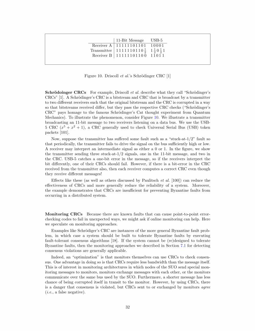
11-Bit Message USB-5Receiver A 1 1 1 1 1 1 0 1 1 0 1 1 0 0 0 1
Transmitter 1 1 1 1 1 1 0 1 1 0 12 1 1
2 0 12 1
Receiver B 1 1 1 1 1 1 0 1 1 0 0 1 1 0 1 1
Figure 10. Driscoll et al.’s Schrodinger CRC [1]
Schrodoinger CRCs For example, Driscoll et al. describe what they call “Schrodinger’sCRCs” [1]. A Schrodinger’s CRC is a bitstream and CRC that is broadcast by a transmitterto two different receivers such that the original bitstream and the CRC is corrupted in a wayso that bitstreams received differ, but they pass the respective CRC checks (“Schrodinger’sCRC” pays homage to the famous Schrodinger’s Cat thought experiment from QuantumMechanics). To illustrate the phenomenon, consider Figure 10. We illustrate a transmitterbroadcasting an 11-bit message to two receivers listening on a data bus. We use the USB-5 CRC (x5 + x2 + 1), a CRC generally used to check Universal Serial Bus (USB) tokenpackets [101].
Now, suppose the transmitter has suffered some fault such as a “stuck-at-1/2” fault sothat periodically, the transmitter fails to drive the signal on the bus sufficiently high or low.A receiver may interpret an intermediate signal as either a 0 or 1. In the figure, we showthe transmitter sending three stuck-at-1/2 signals, one in the 11-bit message, and two inthe CRC. USB-5 catches a one-bit error in the message, so if the receivers interpret thebit differently, one of their CRCs should fail. However, if there is a bit-error in the CRCreceived from the transmitter also, then each receiver computes a correct CRC even thoughthey receive different messages!
Effects like these (as well as others discussed by Paulitsch et al. [100]) can reduce theeffectiveness of CRCs and more generally reduce the reliability of a system. Moreover,the example demonstrates that CRCs are insufficient for preventing Byzantine faults fromoccurring in a distributed system.
Monitoring CRCs Because there are known faults that can cause point-to-point error-checking codes to fail in unexpected ways, we might ask if online monitoring can help. Herewe speculate on monitoring approaches.
Examples like Schrodiger’s CRC are instances of the more general Byzantine fault prob-lem, in which case a system should be built to tolerate Byzantine faults by executingfault-tolerant consensus algorithms [18]. If the system cannot be (re)designed to tolerateByzantine faults, then the monitoring approaches we described in Section 7.1 for detectingconsensus violations are generally applicable.
Indeed, an “optimization” is that monitors themselves can use CRCs to check consen-sus. One advantage in doing so is that CRCs require less bandwidth than the message itself.This is of interest in monitoring architectures in which nodes of the SUO send special mon-itoring messages to monitors, monitors exchange messages with each other, or the monitorscommunicate over the same bus used by the SUO. Furthermore, a shorter message has lesschance of being corrupted itself in transit to the monitor. However, by using CRCs, thereis a danger that consensus is violated, but CRCs sent to or exchanged by monitors agree(i.e., a false negative).
32

7.3 Monitoring Fault-Tolerant Management Software
Thus far we have focused on directly monitoring fault-tolerance at the architectural levelrather than the functional correctness of the software that manages fault tolerance. Thefailure of the fault-tolerant management software affects the functional correctness of asystem, and in its worst manifestation, it can result in a safety violation. Consequently,monitoring for an error in the fault-tolerant management software reduces to traditionalmonitoring of safety properties.
7.3.1 Safety-Critical Systems
Consider the canonical steam-boiler example [102], which has features that is representativeof safety-critical control applications. The following description is taken directly from [102]:
The physical plant consists of a steam boiler. Conceptually, the boiler isheated and the water in the boiler evaporates into steam and escapes the boilerto drive a generator. The amount of heat and, therefore, the amount of steamchanges without any considered control. Nevertheless, the safety depends on abounded water level q in the boiler and steam rate v at its exit. A set of fourequal pumps supply water for steam that leaves the boiler. These four pumpscan be activated or stopped by the controller system.The controller reacts to theinformation of two sensors, the water level sensor and the steam rate sensor, andboth may fail.
The water level has two safety limits, one upper (Mu) and one lower (Ml).If the water level reaches either limit, there is just time enough to shut downthe system before the probability of a catastrophe gets unacceptably high. Thesteam rate has an upper limit of W and, again, if reached the boiler must bestopped immediately.
A monitor would need to verify that v ≤W and Ml ≤ q ≤Mu possibly shutting the systemdown if the bounds are violated.
As noted above, we assume that the SUO is a fault-tolerant system and we are verifyingthat a fault in the fault-tolerant management system does not interfere with the functionalcorrectness by monitoring the steam rate and water levels. In considering the most appro-priate monitoring architecture for this application, we assume that the steam rate sensorand water level sensor communicate to the computers via a shared data bus. Having themonitor attached to the data bus as depicted in Figure 6.4.1 of Section 7 is not appropriatesince this architecture cannot detect Byzantine faults. The single monitor architecture ofFigure 8 in Section 6.4.2 would require each of the nodes to be instrumented to report tothe monitor a copy of the received message. CRC checks can be used to mitigate errors intransit. Implementing this architecture is straightforward, but we must assume that thereare no faults in the monitor, which is a reasonable assumption, given its simplicity. A moresophisticated approach may be a fault-tolerant monitoring system using the architecture inFigure 9 in Section 6.4.3, where each node’s monitor checks the measured values received,data is exchanged among the monitors and votes are taken. This would add an additionallevel of fault-tolerance at the expense of additional complexity.
7.3.2 Traffic Patterns
One can monitor a protocol’s behavior by observing internal state, but this requires someinstrumentation of the protocol in order to insert sensors that transmit the state informationto the monitor. In many cases, this is impractical because the manufacturer will not allowa third-party to access their product, or because the protocol is implemented in silicon asa FPGA or a customized chip. Many protocol properties may be verified by observing
33

the communication traffic and verifying that the messages obey the pattern defined by theprotocol specification that the message fields have the expected value. Although there aresignificant challenges in recognizing the protocol events of interest in a huge stream of dataand verifying properties over that event trace, there has been some progress in this areathat can be applied to critical systems. For instance, Bhargavan et al. [55,56] observe TCPtraffic and verify that a trace of messages between two nodes satisfy properties such as:
• An acknowledgement is generated for at least every other TCP message received.
• Acknowledgement sequence numbers are non-decreasing.
We also discussed BusMoP [32, 33] in Section 4.2 that monitored data transfers on a PCIbus. An example is a property that says any modification to a particular bus control registeronly happens when not in use. It may be possible to apply similar techniques to monitorcommunication patterns for fault-tolerant buses such as TTEthernet.
The most straightforward monitor architecture to monitor bus-traffic patterns is depictedin Figure 6.4.1 in Section 7. As noted above, this architecture cannot be used to detectByzantine faults, but can be employed to monitor messages if there are no Byzantine faults.This may seem a relatively easy solution to engineer, but Bhargavan et.al. [55] show thatsimply viewing the traffic from the point of an external observer is quite difficult since eventsmay be buffered or lost between the monitor and the SUO. The single monitor architectureof Figure 8 in Section 6.4.2 would require each of the nodes to be instrumented to reportto the monitor a copy of the received message. The monitor then checks that the messageis correctly formed and obeys the protocol’s communication pattern. This choice has thedisadvantage that nodes have to be instrumented to send the message to the monitors anda failure on the monitor link could mean that the message received by the monitor differsfrom the message actually received, but CRCs could be employed to mitigate that issue.The distributed monitor in Figure 9 in Section 6.4.3 would use the monitor at each node tocheck the messages received at that node. The monitors may have to communicate, whichas we saw above can be a drawback. The latter two architectural design choices should notrequire as much buffering of the data stream since the nodes would be instrumented to onlysend the packets of interest to the monitor, but this does not mean that messages still cannotbe lost under the right conditions. Regardless of the architecture chosen, data corrupted onthe interface to the monitor could lead to both false positives and false negatives.
34

8 Conclusions
Online monitoring is a promising technique for making safety-critical real-time distributedsystems more reliable. Section 4 surveyed a number of past and recent efforts in softwaremonitoring. Several research groups have had ongoing efforts in the area for over a decadeand have produced impressive tool sets to both create monitors and to instrument the SUO.Consequently, there is a solid foundation of research in online monitoring of conventionalsoftware systems upon which to build. Yet little research to date has focused on hard real-time critical systems, where monitoring can arguably have the most impact in preventingcostly and possibly fatal system failures.
Section 5 introduced the IVHM philosophy of monitoring a vehicle while in motion forwear and tear on the physical systems such as cracks on aircraft wings. We argued thatsoftware monitoring fits in with the IVHM philosophy by monitoring for violations of specificsafety properties, namely, consensus properties.
Sections 6 and 7 explored monitoring frameworks for distributed real-time systems. Wehave described potential monitoring architectures and have discussed their tradeoffs. Wehave also described classes of properties to monitor. We believe this work will provide afoundation for future directed research.
35

References
1. Kevin Driscoll, Brendan Hall, Hakan Sivencrona, and Phil Zumsteg. Byzantine faulttolerance, from theory to reality. In Proceedings of the 22nd International Conferenceon Computer Safety, Reliability and Security SAFECOMP, Lecture Notes in ComputerScience, pages 235–248. Springer, September 2003.
2. John Rushby. Formal methods and digital systems validation for airborne systems.Technical Report CR–4551, NASA, December 1993.
3. Ricky W. Butler and George B. Finelli. The infeasibility of quantifying the reliability oflife-critical real-time software. IEEE Transactions on Software Engineering, 19:3–12,1993.
4. Steven D. Johnson. Formal methods in embedded design. Computer, 36:104–106,November 2003.
5. Chris Bergin. Faulty MDM removed. NASA Spaceflight.com, May18 2008. Available at http://www.nasaspaceflight.com/2008/05/sts-124-frr-debate-outstanding-issues-faulty-mdm-removed/. (DownloadedNov 28, 2008).
6. Chris Bergin. STS-126: Super smooth endeavor easing throughthe countdown to L-1. NASA Spaceflight.com, November 132008. Available at http://www.nasaspaceflight.com/2008/11/sts-126-endeavour-easing-through-countdown/. (Downloaded Feb 3, 2009).
7. NASA - Johnson Flight Center. Space shuttle operational flight rules volume A, A7-104,June 2002. Available from http://www.jsc.nasa.gov (Downloaded Nov 28, 2008).
8. Australian Transport Safety Bureau. In-flight upset event 240 Km North-West ofPerth, WA Boeing Company 777-200, 9M-MRG 1 August 2005. ATSB TransportSafety Investigation Report, 2007. Aviation Occurrace Report - 200503722.
9. C. Johnson and C. Holloway. The dangers of failure masking in fault-tolerant software:Aspects of a recent in-flight upset event. In Instituition of Engineering and TechnologyInternational Conference on System Safety, pages 60–65, 2007.
10. Kerryn Macaulay. ATSB preliminary factual report, in-flight upset, Qantas AirbusA330, 154 Km West of Learmonth, WA, 7 October 2008. Australian Transport SafetyBureau Media Release, November 14 2008. Available at http://www.atsb.gov.au/newsroom/2008/release/2008 45.aspx.
11. Australian Government. In-flight upset 154 Km West of Learmonth 7 October2008 VH-QPA Airbus A330-303. Australian Transport Safety Bureau Aviation Oc-currence Investigation AO-2008-70, 2008. Available at http://www.atsb.gov.au/publications/investigation reports/2008/AAIR/aair200806143.aspx.
12. Nancy A. Lynch. Distributed Algorithms. Morgan Kaufmann, 1996.
13. Lee Pike and Steven D. Johnson. The formal verification of a reintegration protocol.In EMSOFT ’05: Proceedings of the 5th ACM international conference on Embeddedsoftware, pages 286–289, New York, NY, USA, 2005. ACM Press. Available at http://www.cs.indiana.edu/∼lepike/pub pages/emsoft.html.
36
14. Jean-Claude Laprie. Dependability—its attributes, impairments and means. In B. Ran-dell, J.-C. Laprie, H. Kopetz, and B. Littlewood, editors, Predictability DependableComputing Systems, ESPRIT Basic Research Series, pages 3–24. Springer, 1995.
15. Ricky W. Butler. A primer on architectural level fault tolerance. Technical ReportNASA/TM-2008-215108, NASA Langley Research Center, 2008.
16. John Rushby. Bus architectures for safety-critical embedded systems. In Tom Hen-zinger and Christoph Kirsch, editors, EMSOFT 2001: Proceedings of the First Work-shop on Embedded Software, volume 2211 of Lecture Notes in Computer Science, pages306–323, Lake Tahoe, CA, October 2001. Springer-Verlag.
17. Philip Thambidurai and You-Keun Park. Interactive consistency with multiple failuremodes. In 7th Reliable Distributed Systems Symposium, pages 93–100, October 1988.
18. Lamport, Shostak, and Pease. The Byzantine generals problem. ACM Transactionson Programming Languages and Systems, 4:382–401, July 1982.
19. M. H. Azadmanesh and R. M. Kieckhafer. Exploiting omissive faults in synchronousapproximate agreement. IEEE Transactions on Computers, 49(10):1031–1042, 2000.
20. Paul Miner, Alfons Geser, Lee Pike, and Jeffery Maddalon. A unified fault-toleranceprotocol. In Yassine Lakhnech and Sergio Yovine, editors, Formal Techniques, Modelingand Analysis of Timed and Fault-Tolerant Systems (FORMATS-FTRTFT), volume3253 of LNCS, pages 167–182. Springer, 2004. Available at http://www.cs.indiana.edu/∼lepike/pub pages/unified.html.
21. Wilfredo Torres-Pomales, Mahyar R. Malekpour, and Paul Miner. ROBUS-2: A fault-tolerant broadcast communication system. Technical Report NASA/TM-2005-213540,NASA Langley Research Center, 2005.
22. Elizabeth Ann Latronico. Reliability Validation of Group Membership Services for X-by-Wire Protocols. PhD thesis, Carnegie Mellon University, May 2005. Available athttp://www.ece.cmu.edu/∼Ekoopman/thesis/latronico.pdf.
23. B. Schroeder. On-line monitoring: A tutorial. IEEE Computer, 28(6):72–78, 1995.
24. Severine Colin and Leonardo Mariani. Model-based Testing of Reactive Systems, volume3472 of LNCS, chapter Run-time Verification, pages 525–556. Springer Verlag, 2005.
25. N. Delgado, A. Gates, and S. Roach. A taxonomy and catalog of runtime monitoringtools. IEEE Transactions of Software Engineering, 30(12):859–872, 2004.
26. M. Leucker and C. Schallhart. A brief account of runtime verification. Journal of Logicand Algebraic Programming, 2008. To Appear.
27. J. Tsai, K. Fang, H. Chen, and Y. Bi. A noninterference monitoring and replay mech-anism for real-time software testing and debugging. IEEE Transactions on SoftwareEngineering, 16(8):897–916, 1990.
28. P. Dodd and C. Ravishankar. Monitoring and debugging distributed real-time pro-grams. Software - Practice and Experience, 22(10):863–877, 1992.
29. S. Chodrow, F. Jahanian, and M. Donner. Runtime monitoring of real-time systems.In IEEE Real-Time Systems Symposium, pages 74–83, 1991.
30. S. Sankar and M. Mandal. Concurrent runtime monitoring of formally specificed pro-grams. IEEE Computer, 26(3):32–41, 1993.
37

31. J. Gosling, B. Joy, G. Steele, and G. Bracha. The Java Language Specification.Addison-Wesley, 2005. Third Edition.
32. R.Pellizzoni, P. Meredith, M. Caccamo, and G. Rosu. Hardware runtime monitoringfor dependable cots-based real-time embedded systems. In RTSS’08: Proceedings ofthe 29th IEEE Real-Time System Symposium, pages 481–491, 2008.
33. Rodolfo Pellizzoni, Patrick Meredith, Marco Caccamo, and Grigore Rosu. Hardwareruntime monitoring for dependable COTS-based real-time embedded systems. In RTSS’08: Proceedings of the 2008 Real-Time Systems Symposium, pages 481–491, Washing-ton, DC, USA, 2008. IEEE Computer Society.
34. Oliver Arafat, Andreas Bauer, Martin Leucker, and Christian Schallhart. Runtime ver-ification revisited. Technical Report TUM-I05, Technical University of Munich, Octo-ber 2005. Available at http://users.rsise.anu.edu.au/∼baueran/publications/tum-i0518.ps.gz.
35. Z.Manna and A. Pnueli. The Temporal Logic of Reactive and Concurrent Systems:Specification. Springer-Verlag, 1992.
36. F. Laroussinie, N. Markey, and P. Schnoebelen. Temporal logic with forgettable past.In LICS02: Proceeding of Logic in Computer Science 2002, pages 383–392. IEEE Com-puter Society Press, 2002.
37. K. Havelund and G. Rosu. Synthesizing monitors for safety properties. In Tools andAlgorithms for Construction and Analysis of Systems, pages 342–356, 2002.
38. G. Rosu, F. Chen, and T. Ball. Synthesizing monitors for safety properties – thistime with calls and returns. In RV’08: Proceedings of Runtime Verification, 2008. ToAppear.
39. H. Barringer, A. Goldberg, K. Havelund, and K. Sen. Rule-based runtime verification.In Verification, Model Checking, and Abstract Interpretation (VMCAI), number 2937in LNCS. Springer-Verlag, 2004.
40. H. Barringer, D. Rydeheard, and K. Havelund. Rule systems for run-time monitoring:From eagle to ruler. In RV07: Proceedings of Runtime Verification 2007, number 4839in Lecture Notes in Computer Science, pages 111–125. Springer-Verlag, 2007.
41. M. Kim, M. Viswanathan, H. Ben-Abdallah, S. Kannan, I. Lee, and O. Sokolsky.Formally specified monitoring of temporal properties. In 11th Euromicro Conferenceon Real-Time Systems, pages 114–122, 1999.
42. I. Lee, S. Kannan, M. Kim, O. Sokolsky, and M. Viswanathan. Runtime assurancebased on formal specifications. In International Conference on Parallel and DistributedProcessing Techniques and Applications, pages 279–287, 1999.
43. K. Bhargavan, C. A. Gunter, M. Kim, I. Lee, D. Obradovic, O. Sokolsky, andM. Viswanathan. Verisim: Formal analysis of network simulations. IEEE Transac-tions on Software Engineering, 28(2):129–145, 2002.
44. M. Kim, I. Lee, U. Sammapun, J. Shin, and O. Sokolsky. Monitoring, checking, andsteering of real-time systems. Electronic Notes in Theoretical Computer Science, 70(4),2002. Proceeding of 2nd International Conference on Runtime Verification.
45. O. Sokolsky, U. Sammapun, I. Lee, and J. Kim. Run-time checking of dynamic prop-erties. Electronic Notes in Theoretical Computer Science, 144(4):91–108, 2005. Pro-ceeding of 5th International Conference on Runtime Verification.
38

46. K. Havelund and G. Rosu. An overview of the runtime verification tool Java PathEx-plorer. Formal Methods in System Design, 24(2):189–215, 2004.
47. K. Havelund and G. Rosu. Efficient monitoring of safety properties. InternationalJournal on Software Tools for Technology Transfer, 6(2), 2004.
48. Manuel Clavel, Francisco Duran, Steven Eker, Patrick Lincoln, Narcisco Martı-Oliet,Jose Meseguer, and Jose Quesada. Maude: specification and programming in rewritinglogic. Theoretical Computer Science, 285:187–243, 2002.
49. F. Chen, M. D’Amorim, and G. Rosu. A formal monitoring-base framewrok for soft-ware development analysis. In Proceedings of the 6th International Conference on For-mal Engineering Methods (ICFEM’04), number 3308 in Lecture Notes on ComputerScience, pages 357–373. Springer-Verlag, 2004.
50. F. Chen and G. Rosu. Java-MOP: a monitoring oriented programming environment forJava. In Proceedings of the Eleventh International Conference on Tools and Algorithmsfor the construction and analysis of systems (TACAS’05), volume 3440 of Lecture Notesin Computer Science, pages 546–550. Springer-Verlag, 2005.
51. F. Chen and G. Rosu. MOP: an efficient and generic runtime verification framework. InObject Oriented Programming, Systems, Languages, and Applications, pages 569–588,2007.
52. K. Havelund. Runtime verification of C programs. In TestCom/FATES, number 5047in Lecture Notes in Computer Science. Springer-Verlag, 2008.
53. M. Mansouri-Samani and M. Sloman. Monitoring distributed systems (a survey). Im-perial College Research Report DOC92/23, Imperial College of Science and Technologyand Medicine, 1992.
54. A. Bauer, M. Leucker, and C. Schallhart. Model-based runtime analysis of distributedreactive systems. In Proceedings of the 2006 Australian Software Engineering Confer-ence (ASWEC), Sydney, Australia, April 2006. IEEE Computer Society.
55. K. Bhargavan, S. Chandra, P. McCann, and C.A. Gunter. What packets may come:Automata for network monitoring. SIGPLAN Notices, 35(3):209–219, 2001.
56. K. Bhargavan and C. A. Gunter. Requirement for a practical network event recognationlanguage. Electronic Notes in Theoretical Computer Science, 70(4):1–20, 2002.
57. K. Sen, A. Vardhan, G. Agha, and G. Rosu. Efficient decentralized monitoring of safetyin distributed systems. In ICSE’04: Proceedings of 6th International Conference onSoftware Engineering, pages 418–427, 2004.
58. T. Chandra and S. Toueg. Unreliable failure detectors for reliable distributed systems.Journal of the ACM, 43(2):225–267, 1997.
59. Dahlia Malkhi and Michael Reiter. Unreliable intrusion detection in distributed com-putations. In CSF’97: Proceedings of the 10th IEEE Computer Security FoundationsWorkshop 1997, pages 116–124, 1997.
60. A. Doudou and A. Schiper. Muteness detectors for consensus with Byzantine processes.In Proceedings of the 17th ACM Symposium on Principle of Distributed Computing,pages 31–5, 1997.
61. L. Alvisi, D. Malkhi, E. Pierce, and M. Reiter. Fault detection for Byzantine quoroumsystems. IEEE Transaction on Parallel and Distributed Systems, 12(9):996–1007, 2001.
39
62. K. Kihlstrom, L. Moser, and P. Melliar-Smith. Byzantine fault detectors for solvingconsensus. The Computer Journal, 46(1):16–35, 2003.
63. A. Haeberlen, P. Kouznetsov, and P. Druschel. The case for Byzantine fault detection.In Proceedings of the 2nd conference on Hot Topics in System Dependability, 2006.
64. F. Jahanian, R. Rajkumar, and S. Raju. Run-time monitoring of timing constraintsin distributed real-time systems. Real-Time Systems Journal, 7(2):247–273, 1994.
65. T. Savor and R. Seviora. An approach to automatic detection of software failures inreal-time systems. In IEEE Real-Time Technology and Applications Symposium, pages136–147, 1997.
66. R. Alur and T. Henzinger. Logics and models of real time: A survey. In Real TimeTheory and Practice, volume Lecture Notes in Computer Science 600. Springer-Verlag,1992.
67. R. Alur and T. Henzinger. Real time logics: complexity and expressiveness. In FifthAnnual Symposium on Logic in Computer Science, pages 390–401. IEEE ComputerSociety Press, 1990.
68. P. Thati and G. Rosu. Monitoring algorithms for metric temporal logic specifications.Electronic Notes Theoretical Computer Science, 113, 2004.
69. Drusinsky D. On-line monitoring of metric temporal logic wit time-series constraintsusing alternating finite automata. Journal of Universal Computer Science, 12(5):482–498, 2006.
70. D. Basin, F. Klaedtke, S. Muller, and B. Pfitzmann. Runtime monitoring of metricfirst-order temporal properties. In R. Hariharan, M. Mukund, and V. Vinay, editors,Foundations of Software Technology and Theoretical Computer Science, Leibniz In-ternational Proceedings in Informatics, pages 49–60. Internationales Begegnungs- undForschungszentrum fuer Informatik (IBFI), Schloss Dagstuhl, Germany., 2008.
71. Albert Benveniste, Paul Caspi, Stephen A. Edwards, Nicolas Halbwachs, Paul Le Guer-nic, and Robert de Simone. The synchronous languages 12 years later. Proceedings ofthe IEEE, 91(1):64–83, 2003.
72. P. Caspi, D. Pialiud, N. Halbwachs, and J. Plaice. LUSTRE: a declratative language forprogramming synchronous systems. In 14th Symposium on Principles of ProgrammingLanguages, 1987.
73. B. D’Angelo, S. Sankaranarayanan, C. Snchez, W. Robinson, Zohar Manna,B. Finkbeiner, H. Spima, and S. Mehrotra. LOLA: Runtime monitoring of synchronoussystems. In 12th International Symposium on Temporal Representation adn Reasoning,pages 166–174. IEEE Computer Society Press, 2005.
74. A. Mok and G. Liu. Efficient run-time monitoring of timing constraints. In IEEEReal-Time Technology and Applications Symposium, pages 252–262, 1997.
75. C. Lee. Monitoring and Timing Constraints and Streaming Events with TemporalUncertainties. PhD thesis, University of Texas, 2005.
76. S. Ofsthun. Integrated vehicle health management for aerospace platforms. IEEEInstrumentation and Measurement Magazine, pages 21–24, September 2002.
40

77. M. Schwabacher, J. Samuels, and L. Brownston. The NASA integrated vehicle healthmanagement technology experiment for the X-37. In Proceedings of the SPIE AeroSense2002 Symposium. Society of Photo-Optical Instrumentation Engineers, 2002.
78. National Research Council. Decadal survey of civil aeronautics. National AcademiesPress, 2006.
79. RTCA Inc. Software considerations in airborne systems and equipment certification,1992. RCTA/DO-178B.
80. Daniel Jackson, Martyn Thomas, and Lynette I. Millett, editors. Software for Depend-able Systems: Sufficient Evidence. National Academies Press, 2007.
81. John Rushby. Runtime certification. In RV’08: Proceedings of Runtime Verification,Budapest, Hungary, March 30, 2008. Selected Papers, pages 21–35. Springer-Verlag,2008.
82. John Rushby. Just-in-time certification. In 12th IEEE International Conference on theEngineering of Complex Computer Systems (ICECCS), pages 15–24, Auckland, NewZealand, July 2007. IEEE Computer Society. Available at http://www.csl.sri.com/∼rushby/abstracts/iceccs07.
83. Gabor Karsai, Gautam Biswas, Sherif Abdelwahed, Nag Mahadevan, and Eric Man-ders. Model-based software tools for integrated vehicle health management. In SMC-IT’06: Proceedings of the 2nd IEEE International Conference on Space Mission Chal-lenges for Information Technology, pages 435–442. IEEE Computer Society, 2006.
84. Leslie Lamport. Time, clocks, and the ordering of events in a distributed system.Commun. ACM, 21(7):558–565, July 1978.
85. Colin Fidge. Fundamentals of distributed system observation. IEEE Software,13(6):77–83, 1996.
86. Hermann Kopetz. Real-Time Systems. The Kluwer International Series in Engineeringand Computer Science. Kluwer Academic Publishers, 1997.
87. John Rushby. Software verification and system assurance. In Dang Van Hung andPadmanabhan Krishnan, editors, Seventh International Conference on Software Engi-neering and Formal Methods (SEFM), pages 3–10, Hanoi, Vietnam, November 2009.IEEE Computer Society.
88. Hermann Kopetz. The rationale for time-triggered ethernet. In RTSS’08: Proceedingsof the 2008 Real-Time Systems Symposium, pages 3–11. IEEE Computer Society, 2008.
89. Bowen Alpern and Fred B. Schneider. Recognizing safety and liveness. DistributedComputing, 2(3):117–126, 1987.
90. D. Powell. Failure mode assumptions and assumption coverage. In Proceedings of the22nd International Symposium on Fault Tolerant Computing, pages 386–395. IEEEPress, 1992.
91. John Rushby. Systematic formal verification for fault-tolerant time-triggered algo-rithms. IEEE Transactions on Software Engineering, 25(5):651–660, September 1999.
92. Lee Pike. A note on inconsistent axioms in Rushby’s ”systematic formal verification forfault-tolerant time-triggered algorithms”. IEEE Transactions on Software Engineering,32(5):347–348, May 2006. Available at http://www.cs.indiana.edu/∼lepike/pubpages/time triggered.html.
41

93. Lee Pike. Modeling time-triggered protocols and verifying their real-time schedules. InFMCAD’07: Proceedings of Formal Methods in Computer Aided Design, pages 231–238. IEEE, 2007. Available at http://www.cs.indiana.edu/∼lepike/pub pages/fmcad.html. Best Paper Award.
94. V. Rosset, P. Souto, P. Portugal, and F. Vasques. A reliability evaluation of a groupmembership protocol. In Proceedings of SAFECOMP 2007, volume 4680 of LNCS,pages 397–410. Springer, 2007.
95. Elizabeth Latronico and Philip Koopman. Design time reliability analysis of distributedfault tolerance algorithms. International Conference on Dependable Systems and Net-works, pages 486–495, 2005.
96. Elizabeth Latronico, Paul Miner, and Philip Koopman. Quantifying the reliability ofproven SPIDER group membership service guarantees. In DSN ’04: Proceedings ofthe 2004 International Conference on Dependable Systems and Networks, page 275,Washington, DC, USA, 2004. IEEE Computer Society.
97. Theresa C. Maxino and Philip J. Koopman. The effectiveness of checksums for em-bedded control networks. IEEE Transactions on Dependable and Secure Computing,6(1):59–72, 2009.
98. U. Sammapun, I. Lee, and O. Sokolsky. RT-MaC: runtime monitoring and checking ofquantitative and probabilistic properties. In Proceedings of the 11th IEEE InternationalConference on Embedded and Real-Time Computing Systems and Applications, pages147–153, 2005.
99. U. Sammapun, I. Lee, O. Sokolsky, and J. Regehr. Statistical runtime checking ofprobabilistic properties. In RV’07: Proceedings of Runtime Verification, Lecture Notesin Computer Science 4839, pages 164–175, 2007.
100. Michael Paulitsch, Jennifer Morris, Brendan Hall, Kevin Driscoll, Elizabeth Latronico,and Philip Koopman. Coverage and the use of cyclic redundancy codes in ultra-dependable systems. In DSN ’05: Proceedings of the 2005 International Conferenceon Dependable Systems and Networks, pages 346–355. IEEE Computer Society, 2005.
101. Philip Koopman and Tridib Chakravarty. Cyclic redundancy code (CRC) polynomialselection for embedded networks. In DSN ’04: Proceedings of the 2004 InternationalConference on Dependable Systems and Networks, page 145. IEEE Computer Society,2004.
102. J.-R. Abrial, E. Borger, and H. Langmaack, editors. Formal Methods for IndustrialApplications: Specifying and Programming the Steam Boiler Control. Formal Methodsfor Industrial Applications: Specifying and Programming the Steam Boiler Control,1996.
42


REPORT DOCUMENTATION PAGE Form ApprovedOMB No. 0704–0188
The public reporting burden for this collection of information is estimated to average 1 hour per response, including the time for reviewing instructions, searching existing data sources,gathering and maintaining the data needed, and completing and reviewing the collection of information. Send comments regarding this burden estimate or any other aspect of this collectionof information, including suggestions for reducing this burden, to Department of Defense, Washington Headquarters Services, Directorate for Information Operations and Reports(0704-0188), 1215 Jefferson Davis Highway, Suite 1204, Arlington, VA 22202-4302. Respondents should be aware that notwithstanding any other provision of law, no person shall besubject to any penalty for failing to comply with a collection of information if it does not display a currently valid OMB control number.PLEASE DO NOT RETURN YOUR FORM TO THE ABOVE ADDRESS.
Standard Form 298 (Rev. 8/98)Prescribed by ANSI Std. Z39.18
1. REPORT DATE (DD-MM-YYYY)01-02-2010
2. REPORT TYPEContractor Report
3. DATES COVERED (From - To)
4. TITLE AND SUBTITLE
Monitoring Distributed Real-Time Systems:A Survey and Future Directions
5a. CONTRACT NUMBERNNL08AA19B, order NNL08AD13T
5b. GRANT NUMBER
5c. PROGRAM ELEMENT NUMBER
5d. PROJECT NUMBER
5e. TASK NUMBER
5f. WORK UNIT NUMBER645846.02.07.07.07.15.02
6. AUTHOR(S)
Alwyn Goodloe and Lee Pike
7. PERFORMING ORGANIZATION NAME(S) AND ADDRESS(ES)NASA Langley Research Center
Hampton, Virginia 23681-2199
8. PERFORMING ORGANIZATIONREPORT NUMBER
L–ddddd
9. SPONSORING/MONITORING AGENCY NAME(S) AND ADDRESS(ES)National Aeronautics and Space Administration
Washington, DC 20546-0001
10. SPONSOR/MONITOR’S ACRONYM(S)NASA
11. SPONSOR/MONITOR’S REPORTNUMBER(S)
NASA/CR–2010–nnnnnn
12. DISTRIBUTION/AVAILABILITY STATEMENT
Unclassified-UnlimitedSubject Category 64Availability: NASA CASI (443) 757-5802
13. SUPPLEMENTARY NOTES
An electronic version can be found at http://ntrs.nasa.gov.
14. ABSTRACT
Runtime monitors have been proposed as a means to increase the reliability of safety-critical systems. In particular, this report addressesruntime monitors for distributed hard real-time systems. This class of systems has had little attention from the monitoring community.The need for monitors is shown by discussing examples of avionic systems failure. We survey related work in the field of runtimemonitoring. Several potential monitoring architectures for distributed real-time systems are presented along with a discussion of howthey might be used to monitor properties of interest.
15. SUBJECT TERMS
16. SECURITY CLASSIFICATION OF:
a. REPORT
U
b. ABSTRACT
U
c. THIS PAGE
U
17. LIMITATION OFABSTRACT
UU
18. NUMBEROFPAGES
pp
19a. NAME OF RESPONSIBLE PERSONSTI Help Desk (email: [email protected])
19b. TELEPHONE NUMBER (Include area code)(443) 757-5802