MONITOR AND CONTROL OF AN EXCAVATOR ROBOTbobbleheadal.com/490project/Group13_Proposal.pdf ·...
19
QUEEN’S UNIVERSITY DEPARTMENT OF ELECTRICAL AND COMPUTER ENGINEERING ELEC 49X PROJECT PROPOSAL MONITOR AND CONTROL OF AN EXCAVATOR ROBOT Submitted By: Group 13 Alan Lo Ryan Murphy Vuk Zrnic Faculty Supervisor: Dr. K. Hashtrudi-Zaad
Transcript of MONITOR AND CONTROL OF AN EXCAVATOR ROBOTbobbleheadal.com/490project/Group13_Proposal.pdf ·...

QUEEN’S UNIVERSITY
DEPARTMENT OF ELECTRICAL AND COMPUTER ENGINEERING
ELEC 49X PROJECT PROPOSAL
MONITOR AND CONTROL OF AN EXCAVATOR ROBOT
Submitted By:
Group 13
Alan Lo
Ryan Murphy
Vuk Zrnic
Faculty Supervisor:
Dr. K. Hashtrudi-Zaad

2
EXECUTIVE SUMMARY
The goal of the project is to upgrade a commercially available toy excavator so that it can be
controlled remotely though the use of a GUI (graphical user interface). The GUI will display both
measured and calculated information from the excavator, as well as a visual representation
mimicking the movement of the real-life excavator, and will allow for operation when the excavator
is not in line of sight.
The operator will control the excavator using two linear joysticks connected to a PC. The user
commands will be relayed using wireless transmission to the hardware onboard the excavator which
will drive the motors. The excavator track and arm joint angles are monitored by sensors mounted
on the excavator. Motor currents will be monitored in order to compute forces on the bucket. Joint
angles, track rotation, and motor currents are sent to the PC workstation to calculate the position
and orientation of the bucket and the location of the cabin relative to a reference point. This
information is then used to render a real-time 3D model of the excavator in motion, as well as
display all relevant measured and calculated parameters.
The excavator will have two modes of operation. In MODE1, the operator will control each joint
separately. In MODE2, coordinated motion, (See Figure A.1) the operator will command the end-
effector (bucket) motion, and the joint angle changes will be computed by the workstation software.
Two possible extensions of the project are: use of force feedback joysticks, and detection of track
slippage. The force feedback will allow the operator to feel the forces acting on the bucket when the
bucket is loaded or pushing against a static object. Detecting tracks slippage is important when
creating an accurate graphical display of excavator movement.
The estimated cost of this project is $400. This estimate includes replacement parts, assuming the
possibility that parts from previous projects are not fully functional.
The group is composed of a computer engineer, and two electrical engineers. The project is
expected to take six months to complete.

3
TABLE OF CONTENTS
EXECUTIVE SUMMARY .................................................................................................2
1.0 INTRODUCTION .......................................................................................................3
1.1 – PURPOSE ............................................................................................................................................................3
1.2 – WORK OBJECTIVES .......................................................................................................................................3
1.2.1 – Motivation ..................................................................................................................................................... 3
1.2.2 – Project Goals ................................................................................................................................................. 3
1.2.3 – Proposed Solution ......................................................................................................................................... 3
1.3 – WORK SCOPE ...................................................................................................................................................4
2.0 - FUNCTIONAL DESCRIPTION ................................................................................5
2.1 – GENERAL DESCRIPTION ..............................................................................................................................5
2.1.1 – Hardware Description (Non interface) ..........................................................................................................5
2.1.2 – Programming Description (Non interface) ....................................................................................................6
2.1.3 – Programming Description (Graphical User Interface) ..................................................................................7
2.2 – INTERFACE SPECIFICATIONS ....................................................................................................................8
3.0 – DESIGN AND PRODUCTION APPROACH ..........................................................9
3.1 – PROCESS ............................................................................................................................................................9
3.1.1 – Graphical Interface Design Process ..............................................................................................................9
3.1.2 – HC12 Programming .................................................................................................................................... 10
3.1.3 – PC Programming ......................................................................................................................................... 10
3.1.4 – Motorola 68HC12 ...................................................................................................................................... 10
3.1.5 – Sensor Mounting and Calibration ............................................................................................................... 10
3.1.6 – Enclosure Design ........................................................................................................................................ 11
3.2 – DIVISION OF LABOUR .................................................................................................................................11
4.0 – TESTING AND EVALUATION .............................................................................14
4.1 – DESIGN TESTING ..........................................................................................................................................14
4.1.1 – Displacement Accuracy Testing Method ....................................................................................................14
4.1.2 – Joint Angle Accuracy Testing ..................................................................................................................... 14
4.1.3 – Motor Driver Testing .................................................................................................................................. 14
4.1.4 – PC Programming Testing ............................................................................................................................ 15
4.1.5 – Graphical Interface Design Testing ............................................................................................................15
4.2 – SYSTEM TESTING .........................................................................................................................................15
5.0 – RESOURCE REQUIREMENTS ...........................................................................15
5.1 – SCHEDULING ..................................................................................................................................................15
5.2 – MATERIALS AND RESOURCES .................................................................................................................16
5.2.1 – Required Software ....................................................................................................................................... 16
5.2.2 – Required Equipment .................................................................................................................................... 16
5.2.3 – Lab Space Requirements ............................................................................................................................. 17
6.0 – CONCLUSION .....................................................................................................17
7.0 – REFERENCES .....................................................................................................18
APPENDIX A .................................................................................................................19

4
1.0 INTRODUCTION
1.1 – PURPOSE
This purpose of this proposal document is to summarize the ELEC 490 project, Control of an
Excavator Robot, being undertaken by group 13. The intended audience is the course instructor, Dr.
Michael Greenspan, and the faculty supervisor Dr. K. Hashtudi-Zaad.
1.2 – WORK OBJECTIVES
1.2.1 – Motivation
In real-life use, it may be hazardous for the operator of an excavator to work close to the site.
Therefore, the operator may wish to control the excavator remotely where line of sight may not be
possible.
1.2.2 – Project Goals
The project goal is to model the movements of a toy excavator with a real-time 3D virtual model on
a computer monitor so that the excavator can be controlled remotely from a safe distance. This
modeling includes excavator position, and boom and stick orientations. In addition the bucket forces
will be displayed in the graphical interface.
The operator will need to be able to control the excavator arm in two modes of operation. One mode
is the conventional excavator control, where the boom and stick joint motors are controlled
individually by the operator. The other mode is coordinated motion, where the operator controls
only the bucket position.
Some bonus goals of this project are: using force feedback joysticks so the user can feel the forces
on the bucket, and also displaying the track slippage in the virtual model.
1.2.3 – Proposed Solution
To achieve the project goals a commercially available toy excavator will be equipped with sensors
on the joints and tracks in order to determine the movements of those components. Encoders will

4
measure the rotation of the tracks and potentiometers will measure the absolute angle of the joints.
The force on the bucket will be determined by measuring the current driving the joint motors.
To achieve remote control of the excavator, there will be two way wireless transmission between
the excavator processor and the operator’s PC terminal, so that the joystick instructions can be sent
to the motor drivers and the sensor information can be sent back to the PC terminal.
The sensor and force data will be displayed in charts (on the GUI) and will also used to render the
movements in real-time.
Conventional arm motion will be achieved by determining the desired joint angular velocities from
the joystick input and calculating the current required to drive the motors at those velocities.
Coordinated motion will be achieved by determining the desired bucket velocities and using inverse
and forward kinematics computations to calculate the desired angular velocities of the individual
joints.
1.3 – WORK SCOPE
The goal of the project is to complete a working model of a remotely controlled excavator, while
the movements are displays in real time.
The hardware components of the project are as follows:
• mounting and calibration of the sensors,
• identifying and purchasing a new excavator, or installing new motors into the excavator
from a previous year’s project
• testing and repair of the current driver board
• design and construction of rugged enclosure to house current driver board and 68HC12
Software requirements of the project are as follows:
• 68HC12 programming to: read sensors, drive motors, read motor current, and transmit data
to workstation PC
• Graphical User Interface Programming
o Described in section 2.1.3
• Java module programming
o Described in section 2.1.2

5
2.0 - FUNCTIONAL DESCRIPTION
2.1 – GENERAL DESCRIPTION
The final setup of the excavator system is illustrated in Figure 2.1.
4- H Bridge
PCB
digital in
Motors
2-track
sensors
2-joint
sensors
A/D conv
Enclosure
Joint motor
currents
Figure 2.1: Hardware setup
2.1.1 – Hardware Description (Non interface)
An new excavator will be identified and purchased. If the motors on the new excavator do not
properly accept voltages from the current driver or do not perform as expected, the motors will be
replaced with 12 V DC motors. The larger motors will better accept PWM voltages (from the
current driver board), and will not burn out like previous year’s motors. Furthermore, the new
motors will provide more speed and greater velocity changes.
Each track will be equipped with a digital encoder sensor and the arm joints will be equipped with
potentiometer sensors, which send information to the Motorola 68HC12. The sensor mounting
process is detailed in section 3.1.4.
6
An onboard current driver board, equipped with four H-Bridges (and accompanying capacitors and
voltage regulators), will be used to amplify the current from the 68HC12 and drive the motors. An
enclosure will be built to house the current driver board and the 68HC12, and will be mounted
according to 3.1.5. The current driver board design was completed last year. The existing current
driver board needs to be tested and faulty H-bridges and components will be replaced.
A 68HC12 will be onboard the excavator to read the sensors, determine the current in the motors,
send instructions to the current driver board, and communicate through wireless transmission with
the PC.
Full duplex RF digital transceivers (p/n 27994 – existing) and Wireless Cables Inc. Air cable will be
used to send and receive information through wireless transmission between the onboard HC12 and
the PC workstation.
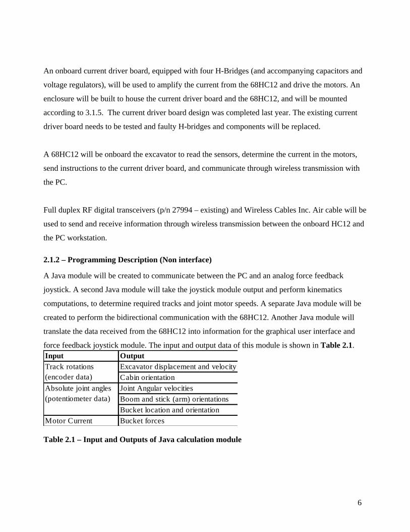
2.1.2 – Programming Description (Non interface)
A Java module will be created to communicate between the PC and an analog force feedback
joystick. A second Java module will take the joystick module output and perform kinematics
computations, to determine required tracks and joint motor speeds. A separate Java module will be
created to perform the bidirectional communication with the 68HC12. Another Java module will
translate the data received from the 68HC12 into information for the graphical user interface and
force feedback joystick module. The input and output data of this module is shown in Table 2.1.
Input Output
Excavator displacement and velocity
Cabin orientation
Joint Angular velocities
Boom and stick (arm) orientations
Bucket location and orientation
Motor Current Bucket forces
Track rotations
(encoder data)
Absolute joint angles
(potentiometer data)
Table 2.1 – Input and Outputs of Java calculation module

7
The 68HC12 code will be created in C and converted to assembly. This code will read the sensor
information from both A/D conversion ports and digital input ports, output information to the
drivers, and have bidirectional communication with the PC.
2.1.3 – Programming Description (Graphical User Interface)
2.1.3.1 – Excavator Model
A 3D model of the excavator will be built use the OpenGL API (Application Programming
Interface). The model will be hierarchical in nature, with the excavator as the parent, with the boom,
stick and bucket as its children. This will allow for the boom, stick and bucket to act independently,
but are still owned by the excavator, so when the excavator moves, each of these elements will
move with it.
2.1.3.2 – Environment Model
A 3D model of the environment in which the excavator will reside in will be built using the
OpenGL API. The model will also be hierarchical in nature, with the entire environment as the
parent, as various objects for obstacles as its children. This will potentially be mirrored in the real
world by constructing a similar environment out of cardboard.
2.1.3.3 – 2D GUI Elements
The 2D elements, such as the interface bar at the bottom of the screen, and the various windows
showing the current status of the excavator will be built using the OpenGL API.
2.1.3.4 – GUI Logic
The GUI logic will be built using C++. The logic will include the interactions between the
excavator and the boom and stick, and the excavator with the environment. It will define how the
excavator can move in the environment (e.g. the maximum angle that the boom and stick can take,
the turning radius of the excavator). The GUI logic will also include logic to control the excavator
based on information sent from the Java module which translates the data received from the
68HC12 (e.g. angles, torque, forces etc)

8
2.2 – INTERFACE SPECIFICATIONS
The operator will control the excavator through the use of two analog joysticks. Analog control was
selected in order for the operator to have control over the velocity of the excavator and the boom
and stick. One joystick will be used to control the excavator tracks and the other to control the
boom and stick. The control scheme is shown in Table 2.2. for conventional joint control (MODE
1), and the control scheme for coordinated motion (MODE 2) is shown in Table 2.3.
Joystick Direction Functionality
1 ñ Moves the excavator forwards by rolling both tracks forward
1 ò Moves the excavator backwards by rolling both tracks backward
1 ð Turns the excavator clockwise by rolling only the right track
1 ï Turns the excavator counter-clockwise by rolling only the left track
2 ñ Extends the stick.
2 ò Retracts the stick.
2 ð Extends the boom.
2 ï Retracts the boom.
Table 2.2 – Control scheme for the two analog joysticks with joint control.
Joystick Direction Functionality
1 ñ Moves the excavator forwards by rolling both tracks forward
1 ò Moves the excavator backwards by rolling both tracks backward
1 ð Turns the excavator clockwise by rolling only the right track
1 ï Turns the excavator counter-clockwise by rolling only the left track
2 ñ Moves the bucket vertically up
2 ò Moves the bucket vertically down
2 ð Moves the bucket horizontally away from the body
2 ï Moves the bucket horizontally toward the body
Table 2.2 – Control scheme for the two analog joysticks with coordinated motion.
The output for the user will be a graphical user interface on the PC monitor. A 3D model of the
environment and the excavator will be developed. Since the objects are 3D objects, the camera can
be put anywhere in the system, allowing for a number of different views from a third person
perspective, as well as a view from the first person perspective. A mock-up of the proposed
graphical interface is shown in Figure 2.2.

9
Figure 2-2: Mock up of proposed graphical interface.
Windows on the outer edges of the screen will display information such as the velocity of the
excavator, as well as torque, angle and force information related to the boom and the stick. As an
optional interface, a force feedback joystick will be used so the operator can feel the forces on the
bucket.
3.0 – DESIGN AND PRODUCTION APPROACH
3.1 – PROCESS
3.1.1 – Graphical Interface Design Process
The graphical interface will be built using C++ and OpenGL. C++ is a high level object oriented
coding language which will be used to build the logic for the graphical interface.

10
3.1.2 – HC12 Programming
The HC12 code will first be written in C and then converted to assembly and loaded onto the chip
through a serial cable. There is some C code from previous groups which will be used for reference.
3.1.3 – PC Programming
The PC Programming, with the exception of the graphical interface, will be done in Java. There is
some Java code from previous groups which may be reusable or used for reference.
3.1.4 – Motorola 68HC12
The HC12 was chosen over the HC11 after reading the recommendation of last year’s group.
According to them, use of the HC12 will allow easier control of PWM signals. [1]
Even though the HC12, which only has 32KB of memory could not hold the code from the group
two years ago [2], this should not be a problem since the current plan is to do the bulk of the
computations in the PC workstation.
3.1.5 – Sensor Mounting and Calibration
“The sensor devices were mounted by drilling through the plastic chassis and attaching threaded
rods. A plastic mount was then attached to the rods using nuts, and the potentiometers and encoders
were attached to the mounts also using nuts. The potentiometer for the boom joint was connected to
the joint shaft using a metal sleeve in order to avoid any slippage. This setup provided much more
sturdiness than that of previous years.” [2] The two digital encoders and the two potentiometers left
over from last year must be tested, and faulty sensors will be replaced before mounting (one
encoder is already known to be bad). The position of one of the encoder is marked B in Figure 3.1.
The other encoder will be mounted on the other track in the same position. The positions of the
potentiometers are marked A in Figure 3.1.
11
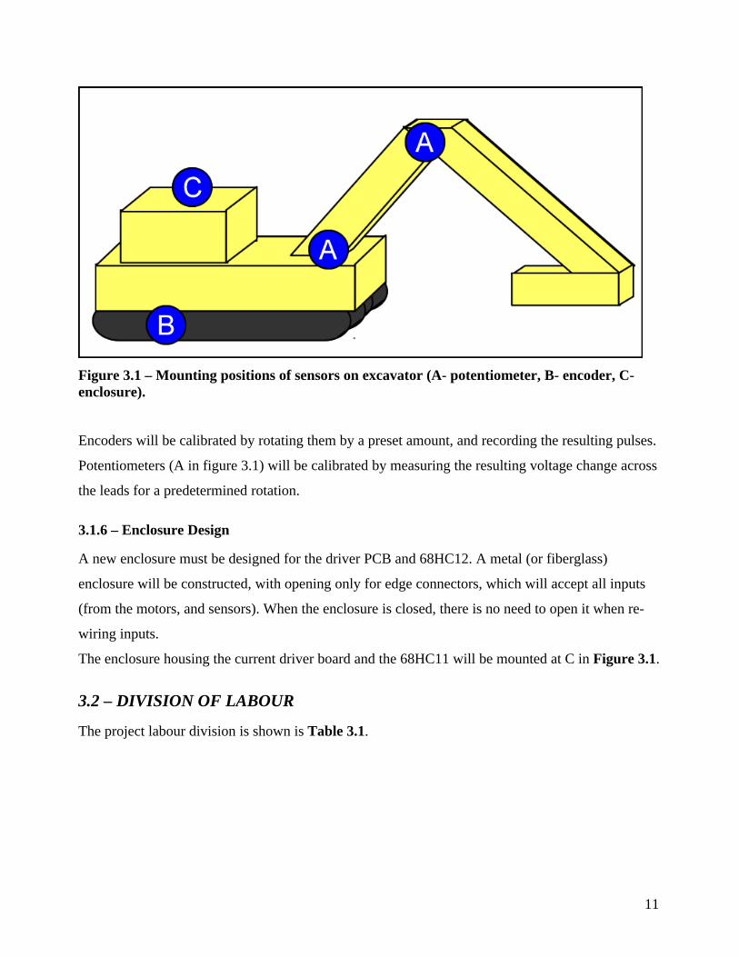
Figure 3.1 – Mounting positions of sensors on excavator (A- potentiometer, B- encoder, C-
enclosure).
Encoders will be calibrated by rotating them by a preset amount, and recording the resulting pulses.
Potentiometers (A in figure 3.1) will be calibrated by measuring the resulting voltage change across
the leads for a predetermined rotation.
3.1.6 – Enclosure Design
A new enclosure must be designed for the driver PCB and 68HC12. A metal (or fiberglass)
enclosure will be constructed, with opening only for edge connectors, which will accept all inputs
(from the motors, and sensors). When the enclosure is closed, there is no need to open it when re-
wiring inputs.
The enclosure housing the current driver board and the 68HC11 will be mounted at C in Figure 3.1.
3.2 – DIVISION OF LABOUR
The project labour division is shown is Table 3.1.

12
TASK PRIMARY Contact SECONDARY Contact
Ryan Murphy
Vuk Zrnic
Ryan Murphy
Vuk Zrnic
Ryan Murphy
Vuk Zrnic
Wireless Data Transmission Vuk Zrnic Ryan Murphy
Enclosure Design and Manufacturing Vuk Zrnic Ryan Murphy
68HC12 Programming Ryan Murphy Vuk Zrnic
Ryan Murphy
Vuk Zrnic
Joystick input reading Ryan Murphy Alan Lo
Coordinated Motion Algorithm Ryan Murphy Vuk Zrnic
Ryan Murphy
Vuk Zrnic
Ryan Murphy
Vuk Zrnic
Ryan Murphy
Vuk Zrnic
Ryan Murphy
Vuk Zrnic
Vuk Zrnic
Ryan Murphy
Force Feedback Joystick Ryan Murphy
(Time Permitting) Alan Lo
Slippage Detection Vuk Zrnic
(Time Permitting) Alan Lo
Identify and purchase new excavator, or
purchase new motors if a suitable
excavator cannot be found
Alan Lo
Existing component testing Alan Lo
Installation of hardware components
onto excavator
Alan Lo
Sensor and Motor calibration and data
gathering
Alan Lo
Build 3D model of excavator with
OpenGL
Alan Lo
Build 3D model of environment with
OpenGL
Alan Lo
Build 2D elements of GUI with
OpenGL (windows, taskbar)
Alan Lo
Develop logic to take in information
from sensors through workstation PC in
C++
Alan Lo
Force Measurement at Bucket Alan Lo
Vuk Zrnic
Ryan Murphy
Table 3.1 – Division of Labour
Alan Lo is a computer engineer with extensive object oriented coding background in both academic
and professional settings, and is taking a computer graphics course detailing OpenGL (CISC 454).

13
Ryan Murphy is an electrical engineer with knowledge of object oriented coding and assembly
language coding and is taking a robotics course detailing forward, inverse and differential
Kinematics. (ELEC 448)
Vuk Zrnic is an electrical engineer with strong interest in robotics and is currently taking ELEC
448. Vuk has acquired hardware and mechanical design skills through his experience at Celestica
Inc., where he worked as a Prototype Engineer.
4.0 – TESTING AND EVALUATION
4.1 – DESIGN TESTING
4.1.1 – Displacement Accuracy Testing Method
Displacement accuracy will tested by comparing the calculated displacement and the actual
displacement of the excavator in both forward and reverse directions. If errors occur, the data
directly from the encoders (rotations) will be analyzed first, to ensure the encoders are functioning,
then the logic which computes the displacement from the degrees of rotation. For this test, slippage
must be eliminated.
4.1.2 – Joint Angle Accuracy Testing
Joint angle accuracy will be tested much like displacement accuracy.
Actual angles and angle changes will be compared to the angles calculated. If errors occur, the data
directly from the potentiometers (absolute angle) will be analyzed first to ensure the potentiometers
are functioning, then the logic which computes the angle from the potentiometer reading.
4.1.3 – Motor Driver Testing
Motor drivers will be tested by comparing the actual motor velocities with the desired velocities.
This will first be done be imputing arbitrary velocities, and later using the joysticks to control the
motors.

14
4.1.4 – PC Programming Testing
The joystick interface program will be tested by writing a small program which outputs the
calculated x-y coordinate of the joystick position to the screen. All other PC programs mentioned
will be tested using different program techniques such as path testing, and black box testing.
4.1.5 – Graphical Interface Design Testing
The graphical interface will be tested and evaluated primarily in a subjective manner. A qualitative
observation will be made on how well the excavator in the graphical interface matches the actual
movement of the real-life excavator. All the physical data such as velocity and displacement of the
excavator, as well as position, torque and angle information in regards to the stick and boom will be
verified through the testing of the hardware, and assumed to be correct data. For this test, slippage
must be eliminated.
4.2 – SYSTEM TESTING
When each component is functioning and tested by the methods in Section 4.1, the system as a
whole will be subjectively tested by normal operation. The input will be tested by seeing if the
excavator moves as directed from the joysticks in MODE1 (joint control) and MODE2 (bucket
control-coordinated motion). The excavator movements must also be properly represented by the
virtual model.
5.0 – RESOURCE REQUIREMENTS
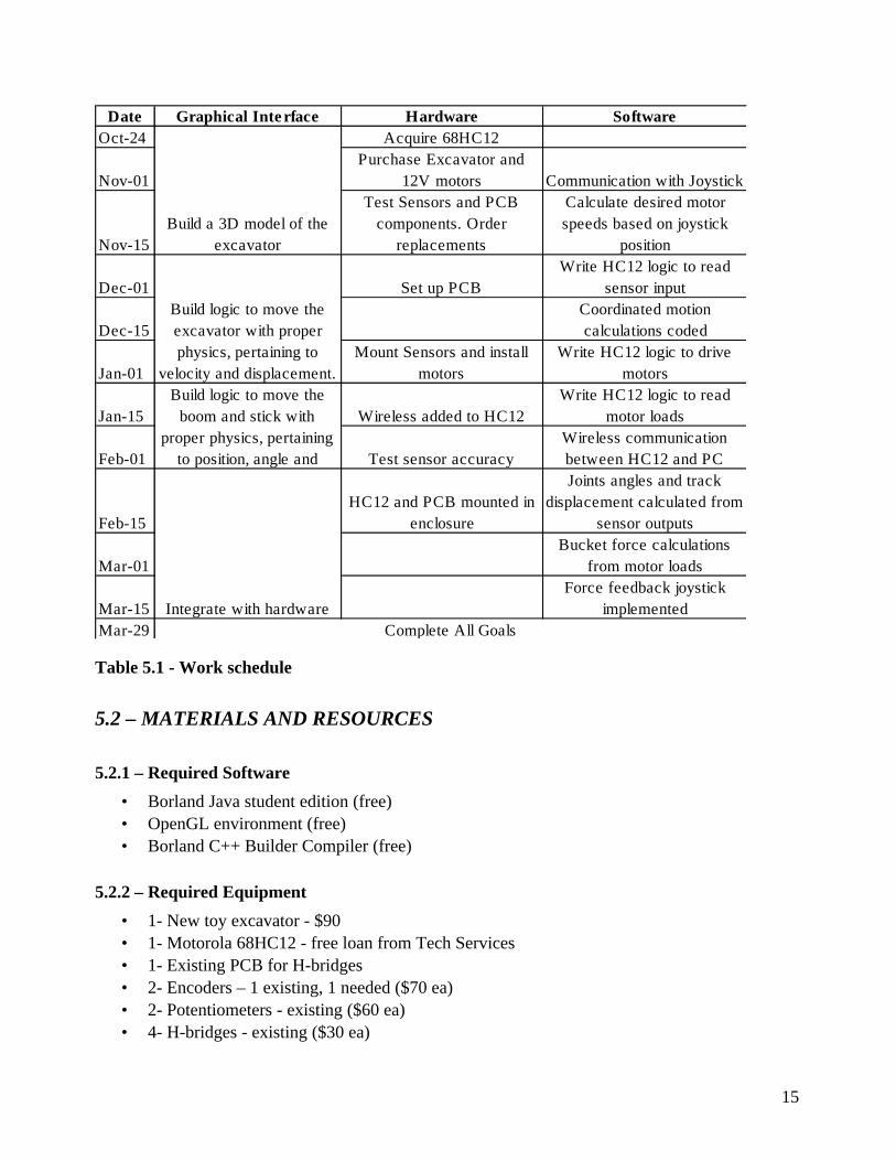
5.1 – SCHEDULING
The work schedule is shown in Table 5.1.
15
Date Graphical Inte rface Hardware Software
Oct-24 Acquire 68HC12
Nov-01
Purchase Excavator and
12V motors Communication with Joystick
Nov-15
Test Sensors and PCB
components. Order
replacements
Calculate desired motor
speeds based on joystick
position
Dec-01 Set up PCB
Write HC12 logic to read
sensor input
Dec-15
Coordinated motion
calculations coded
Jan-01
Mount Sensors and install
motors
Write HC12 logic to drive
motors
Jan-15 Wireless added to HC12
Write HC12 logic to read
motor loads
Feb-01 Test sensor accuracy
Wireless communication
between HC12 and PC
Feb-15
HC12 and PCB mounted in
enclosure
Joints angles and track
displacement calculated from
sensor outputs
Mar-01
Bucket force calculations
from motor loads
Mar-15
Force feedback joystick
implemented
Mar-29 Complete All Goals
Build a 3D model of the
excavator
Build logic to move the
excavator with proper
physics, pertaining to
velocity and displacement.
Build logic to move the
boom and stick with
proper physics, pertaining
to position, angle and
Integrate with hardware
Table 5.1 - Work schedule
5.2 – MATERIALS AND RESOURCES
5.2.1 – Required Software
• Borland Java student edition (free)
• OpenGL environment (free)
• Borland C++ Builder Compiler (free)
5.2.2 – Required Equipment
• 1- New toy excavator - $90
• 1- Motorola 68HC12 - free loan from Tech Services
• 1- Existing PCB for H-bridges
• 2- Encoders – 1 existing, 1 needed ($70 ea)
• 2- Potentiometers - existing ($60 ea)
• 4- H-bridges - existing ($30 ea)

16
• 4- 12 V motors - $20 ea
• 1- Full Duplex Aircable transceiver set - existing
• 1- Enclosure - $50
• 2- Force Feedback Joysticks – 1 existing, 1 needed ($80)
• Connectors and discretes – $0 (available in Tech. Services)
5.2.3 – Lab Space Requirements
Estimated 5 hrs per week needed.
6.0 – CONCLUSION
This year’s excavator project will build on previous year’s efforts by testing, repairing and
modifying existing software and hardware systems, as well as implementing several important new
functional features.
The tested hardware (current driver board and HC11 board) will be housed in a newly designed,
rugged enclosure, which will keep the hardware protected, and all input pins easily accessible
(without the need to open the enclosure). Furthermore, the excavator will be completely re-wired
this year.
A new graphical user interface will allow the user to safely and effectively control the excavator
when it is outside direct line of sight. The operator will monitor excavator movement and position,
as well as boom and stick positions and joint angles through a real-time, 3D virtual simulation.
Furthermore, angular joint velocities and track speeds will be calculated and displayed on the GUI.
This year’s system will also have the capability of detecting forces at the bucket tip, and this
information will be displayed on the GUI.
In addition to being able to control each joint independently, coordinated motion will allow the user
to command the bucket tip motion along the x and y axes (joint angles will be computed by the
software onboard the workstation PC). This feature will greatly increase ease of operation.
Two optional features for this year’s project are use of force feedback joysticks, and detection of
track slippage. Time permitting, these features will be implemented on the excavator system, and
will be integrated into the GUI.
The group is looking forward to this year’s challenge, and is excited about showcasing a fully
functional model at the end of the year.

17
7.0 – REFERENCES
[1] Shamir Charania, Noel Johnston, Tavis MacCallum, (2004-2005). ELEC490 Project –
Remote Control of An Excavator Robot , Second Generation,
Queen’s University, Kingston, Canada.
[2] Matthew Cole, Lee-Anne Edmunds, Danah Kassabian, (2003-2004). ELEC490 Project –
Control of An Excavator,
Queen’s University, Kingston, Canada.

18
APPENDIX A
Figure A.1 – Illustration of Coordinated Motion