Monica Plus Wood Pellet Burning Heater Owner’s ... · Monica Plus Wood Pellet Burning Heater...
37
Monica Plus Wood Pellet Burning Heater Owner’s & Installation Manual PLEASE READ THIS ENTIRE MANUAL BEFORE INSTALLATION AND USE OF THIS PELLET BURNING ROOM HEATER. FAILURE TO FOLLOW THESE INSTRUCTIONS COULD RESULT IN PROPERTY DAMAGE, BODILY INJURY, OR EVEN DEATH. Contact your local building or fire official about restrictions and installation inspection requirements in your area. economical user friendly leading design healthy home visible flame clean air approved
-
Upload
phungthien -
Category
Documents
-
view
228 -
download
2
Transcript of Monica Plus Wood Pellet Burning Heater Owner’s ... · Monica Plus Wood Pellet Burning Heater...

Monica Plus Wood Pellet Burning HeaterOwner’s & Installation Manual
PLEASE READ THIS ENTIRE MANUAL BEFORE INSTALLATION AND USE OF THIS PELLET BURNING ROOM HEATER. FAILURE TO FOLLOW THESE INSTRUCTIONS COULD RESULT IN PROPERTY DAMAGE, BODILY
INJURY, OR EVEN DEATH.
Contact your local building or fire official about restrictions and installation inspection requirements in your area.
economicaluserfriendly
leading design
healthy home
visibleflame
clean airapproved

2
Owner’s Section
Table of Contents
1. Introduction ........................................................................................41.1 Specifications .......................................................................................................41.2 Safety Warnings & Recommendations ...............................................................51.3 Deciding where to locate your wood pellet burning heater ..............................51.4 Ash .........................................................................................................................51.5 Clinkering ...............................................................................................................51.6 Filling Fuel Hopper ................................................................................................51.7 Flammable Liquids ................................................................................................61.8 Installation .............................................................................................................61.9 Operating Instructions ..........................................................................................71.10 Safety Devices .......................................................................................................71.11 Responsibility ........................................................................................................7
1.12 Spare Parts ............................................................................................................7
2. Operating your Pellet Fire.................................................................82.1 Description of the Controls ..................................................................................82.2 Description of Remote control .............................................................................82.3 Switching on the Stove .........................................................................................82.4 Operating Precautions ..........................................................................................82.5 Priming of the Screw (Auger) ...............................................................................82.6 Description of Menus ............................................................................................92.7 Setting the Clock (Clock Set Menu) ...................................................................102.8 Chronothermostat Setting Menu .......................................................................102.9 Setting the Language (Language Menu) ...........................................................142.10 Settings Menu ......................................................................................................142.11 Description of the functions ..............................................................................142.12 Mode with Room Sensor Supplied ....................................................................142.13 External Thermostat Mode .................................................................................142.14 Stove Status Menu ..............................................................................................152.15 Working Hours Menu ..........................................................................................152.16 Description of Screen Displays .........................................................................16
2.17 Description of Alarms .........................................................................................16
3. Maintenance and Cleaning .............................................................183.1 Cleaning the surfaces .........................................................................................18

3
3.2 Cleaning the fire pot before and after each lighting ........................................183.3 Cleaning the FIREX 600 ......................................................................................193.4 Cleaning the combustion chamber ...................................................................203.5 Cleaning the Flu .................................................................................................203.6 Access to the inspection hatches for cleaning the smoke ............................213.7 Frequency of Component Cleaning ..................................................................21
3.8 Cleaning the Ashes Draw ...................................................................................22
4. Guarantee .........................................................................................234.1 Certificate of Guarantee .....................................................................................23
4.2 Conditions of Guarantee ....................................................................................23
5. What are Wood Pellets? ..................................................................246. The Components of the Stove ........................................................24

4
1. IntroductionThis manual is designed for both the technician and the home owner.
Please read this entire manual before installing or operating your Ecoteck Monica Plus Freestanding Wood Pellet Burning Heater. Failure to follow these instructions may result in property damage, bodily injury or even death. Any unauthorized modification of the appliance or use of replacement parts not recommended by the manufacturer is prohibited. All national and local regulations shall be complied with when installing this appliance. Your local Nature’s Flame dealer will be happy to assist you in obtaining information with regards to your local building codes and installation restrictions.
1.1 Specifications
1.1.1 Rating label Location
Ecoteck Monica Plus Freestanding: The rating label is located on the back of unit.
*Note: Consumption will vary with the type of fuel used.
IMPORTANT: The above values were found during testing and may vary with the fuel type, climate and installation style.
1.1.2 Clearances to Combustibles
This pellet heater requires floor protection which must be non-combustible, extending beneath the stove the full width and depth of the unit including (150mm) in front for ember protection.
AS/NZS2918 states that a 300mm forward projecting and 200mm side projecting floor protector must be used from any door opening extremity as an absolute minimum. Due to the operating nature of the Monica Plus pellet heater where opening the door causes a loss of vacuum and the fire will shut down completely, meaning the likelihood of any hot embers or burning fuel escaping from the combustion chamber is extremely minimal, a 150mm forward projecting floor protector will be sufficient.
Classification Testing Standard Description
Class I IP-20 Efficiency: AS/NZS 5078:2007 Appliance: AS/NZS 4866:2007
Residential Wood Pellet Heater
Voltage 220- 240 Volt Current: 2.92 – 3.18 Amps Frequency: 50Hz
Max Power Requirement550 watts
Unit with full hopper: 145kg Hopper Capacity: 15kg
Mean Flue Gas Temp –High: 193 degrees
Mean Flue Gas Temp-Medium: 174 degrees
Mean Flue Gas Temp-Low: 158 degrees
Fuel Consumption –High: 1.43 kg per hour
Fuel Consumption –Medium: 1.16kg per hour
Fuel Consumption –Low: 0.99kg per hour
Heat/Power Output – High: 6.5kw
Heat/Power Output –Medium: 6.1kw
Heat/Power Output –Low: 5.0kw
Average Particular Emissions (dry weight) 0.31gms per kg
Average Emissions Rate18mg/MJ
Average Efficiency85%
Gross Calorific Value of pellets (dry weight)
20.24MJ/kg
Fuel Type:Wood pellets – 6mm dia, - complying with draft standard AS/NZS 4014.6 2008

5
2. Safety Warnings & RecommendationsPellet quality is important, please read the following:
Your pellet heater has been designed to burn ¼” (6mm) diameter wood pellets, manufactured to the AS/NZS 4014.6 only.
DO NOT use this appliance as an incinerator.
DO NOT use unsuitable and non recommended fuels, including liquid fuels as this will void any warranties stated in the manual.
The performance of your pellet heater is greatly affected by the type and quality of wood pellets being burned. As the heat output of various quality wood pellets differs, so will the performance and heat output of the pellet stove.
Caution: It is important to select and use only pellets that are dry and free of dirt or any impurities such as high salt content. Wood pellets manufactured to the AS/NZS 4014.6 standard are recommended. Dirty fuel will adversely affect the operation and performance of the unit and will void the warranty. The Pellet Fuel Industries (PFI) has established standards for wood pellet manufacturers. We recommend the use of pellets that meet or exceed these standards. Ask your dealer for a recommended pellet type.
2.1 Deciding where to locate your wood pellet burning heater1. Do not install the pellet heater in a bedroom or room where people sleep.2. Locate the pellet heater in a large and open room that is centrally located in the house.
This will optimize heat circulation.3. Check clearances to combustibles (refer page 30).
2.2 Ash
The ash content of the fuel and operation of your stove will directly determine the frequency of cleaning. The use of high ash fuels may result in the stove needing to be cleaned daily. A low ash fuel may allow longer intervals between cleaning.
2.3 Clinkering
Clinkers are silica (sand) or other impurities in the fuel that will form a hard mass during the burning process. This hard mass will block the air flow through the Burn Pot Liner and affect the performance of the stove. Any fuel, even approved types, may clinker. Check the Burn Pot Liner daily to ensure that the holes are not blocked with clinkers. If they become blocked, remove the liner (when the unit is cold) and clean/scrape clinkers out. Clean the holes with a small pointed object if required. Refer to the section Routine Cleaning and Maintenance.
2.4 Filling Fuel Hopper
Check hopper for foreign objects, then empty the bag of pellets into the hopper. DO NOT OVER FILL as miscellaneous pellets could smoke if left to rest on an operating heater.
Store pellets at least one metre (1m) away from the pellet stove.
Warning: parts of the appliance, especially the external surfaces, will be hot to touch when in operation so use due care.
6
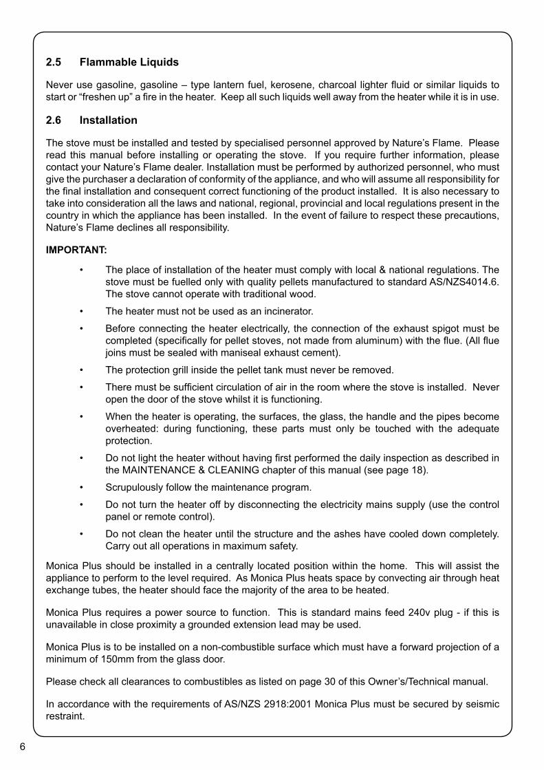
2.5 Flammable Liquids
Never use gasoline, gasoline – type lantern fuel, kerosene, charcoal lighter fluid or similar liquids to start or “freshen up” a fire in the heater. Keep all such liquids well away from the heater while it is in use.
2.6 Installation
The stove must be installed and tested by specialised personnel approved by Nature’s Flame. Please read this manual before installing or operating the stove. If you require further information, please contact your Nature’s Flame dealer. Installation must be performed by authorized personnel, who must give the purchaser a declaration of conformity of the appliance, and who will assume all responsibility for the final installation and consequent correct functioning of the product installed. It is also necessary to take into consideration all the laws and national, regional, provincial and local regulations present in the country in which the appliance has been installed. In the event of failure to respect these precautions, Nature’s Flame declines all responsibility.
IMPORTANT:
• The place of installation of the heater must comply with local & national regulations. The stove must be fuelled only with quality pellets manufactured to standard AS/NZS4014.6. The stove cannot operate with traditional wood.
• The heater must not be used as an incinerator.
• Before connecting the heater electrically, the connection of the exhaust spigot must be completed (specifically for pellet stoves, not made from aluminum) with the flue. (All flue joins must be sealed with maniseal exhaust cement).
• The protection grill inside the pellet tank must never be removed.
• There must be sufficient circulation of air in the room where the stove is installed. Never open the door of the stove whilst it is functioning.
• When the heater is operating, the surfaces, the glass, the handle and the pipes become overheated: during functioning, these parts must only be touched with the adequate protection.
• Do not light the heater without having first performed the daily inspection as described in the MAINTENANCE & CLEANING chapter of this manual (see page 18).
• Scrupulously follow the maintenance program.
• Do not turn the heater off by disconnecting the electricity mains supply (use the control panel or remote control).
• Do not clean the heater until the structure and the ashes have cooled down completely. Carry out all operations in maximum safety.
Monica Plus should be installed in a centrally located position within the home. This will assist the appliance to perform to the level required. As Monica Plus heats space by convecting air through heat exchange tubes, the heater should face the majority of the area to be heated.
Monica Plus requires a power source to function. This is standard mains feed 240v plug - if this is unavailable in close proximity a grounded extension lead may be used.
Monica Plus is to be installed on a non-combustible surface which must have a forward projection of a minimum of 150mm from the glass door.
Please check all clearances to combustibles as listed on page 30 of this Owner’s/Technical manual.
In accordance with the requirements of AS/NZS 2918:2001 Monica Plus must be secured by seismic restraint.

7
2.7 Operating Instructions
The heater is completely automated and will self-regulate the ignition phase, five levels of power and the switching off phase, guaranteeing safe functioning. The burn pot used for combustion allows most of the ashes produced by the combustion of the pellets to fall into the collection drawer. However, it is recommended that you check the burn pot every day, as not all pellets have high standards of quality and could leave residue that is difficult to remove. The glass has special air circulation for self-cleaning, however, a slight greyish film cannot be avoided after a few hours of functioning. Pellets with a diameter of 6mm, manufactured to the AS/NZ4014.6 or higher must be used with the stove.
2.8 Safety Devices
The heater is fitted with sophisticated safety systems so that, in the case of breakage of one of the individual parts or defects in the flue, no damage will be caused to the stove and the room in which it is installed. In any case, when a problem arises, the pellets stop falling immediately and the switch off phase is activated. The corresponding alarm will be shown on the display. The details can be seen in the chapter on the alarms (page 16).
2.9 Responsibility
Nature’s Flame declines all responsibility, both civil and criminal, with the delivery of this manual, for any accidents deriving from partial or total failure to observe the instructions it contains.
Nature’s Flame declines all responsibility deriving from the improper use of the stove, from its incorrect use by the user, by unauthorised modifications and/or repairs or from the use of spare parts which are not original. The manufacturer declines all direct civil or criminal responsibility due to:
• Poor maintenance.
• Failure to observe the instructions in the manual.
• Use not compliant with the safety instructions.
• Installation that is not compliant with the regulations in force in the country.
• Installation by personnel who are not qualified or authorized.
• Modifications and repairs that are not authorized by the manufacturer.
• Use of spare parts that are not original.
• Exceptional events.
2.10 Spare Parts
Use original spare parts only. Do not wait for the components to be worn before replacing them. Replace a worn component before it is completely broken to prevent any accidents caused by the sudden breakage of components. Perform the periodic maintenance checks as described in the dedicated chapter on Maintenance (page 18).

8
3. Operating your Pellet Fire3.1 Description of the Controls
3.2 Description of Remote control
IR receiver for remote control (12 volts batteries code LRV08 not included).
3.3 Switching on the Stove1. Ensure burn pot is clean and free of ash2. Slide the heat exchange cleaner in and out three times3. To turn unit on hold down button ‘3’ (ON/OFF)4. Control Screen will show START5. Use buttons ‘1’ or ‘2’ to select desired heat6. Use buttons ‘4’ or ‘5’ to select desired thermostat setting7. To turn unit off hold down button ‘3’ (ON/OFF)8. Control Screen will show FINAL CLEANING
3.4 Operating Precautions
• In case of faulty operation turn the stove off pressing button no. 3.
• Do not manually load the fire pot with pellets.
• Any build up of unburned pellets inside the fire pot after repeatedly trying to light the stove, must be removed before further attempts.
• Do not use any fuels other than wood pellets.
• Should the ignition system be faulty, do not attempt to light the stove using flammable materials.
3.5 Priming of the Screw (Auger)
To prime the screw/auger (when the stove is new or has been completely run out of fuel, the loading
20°C10:00 20°C
OFF
P1 : Turns heat level downP2 : Turns heat level upP3 : Turns fiire on-offP4 : Turns thermostat downP5 : Turns thermostat upP6 : Menu buttonP7 : Menu button
1
2
4
5
• P1 - P2 Temperature setting: allow setting the value of the desired room temperature from a maximum of 40°C to a minimum of 6°C.
• P4 - P5 Power setting: allows setting the value of the working power from a minimum of 1 to a maximum value of 5 displays.
• P1 + P4 ON/OFF: pressed for 2 seconds, they switch on and off the stove manually.
Heat ExchangeCleaner/Scraper

9
screw/auger is empty), proceed as follows:
1. Turn the stove off completely, using the general switch on the back2. The display will show FINAL CLEANING and then OFF.3. Turn the the power back on, using the general switch on the back.4. Keep button P4 pressed for 2 seconds. CLOCK SETTING MENU will appear.5. Press button P4 until the display shows STOVE STATUS MENU
3.6 Description of Menus
The stove has various functions, available in its individual programming menus. Some of these menus are accessible by the user, others are protected by a password and accessible only by a Service Technician.
The menus are as follows:
• CLOCK SETTING Menu
• CHRONO THERMOSTAT Menu
• LANGUAGE Menu
• SETTINGS Menu
• STOVE STATUS Menu
• WORKING HOURS Menu
• DATA BASE Menu (protected by a password)
2000 150° SCREW 0 STATE
THE SCREW IS IDLE
PRESS BUTTON P5 TO ACTIVATE THE SCREW (AUGER)
2000 150° SCREW 1 STATE
SCREW ACTIVATED
Repeat the operation several times until you can see the pellets fall into the fire pot.
This operation is possible only if the stove is in final cleaning or shut down
IMPORTANT AFTER LOADING THE SCREW/AUGER, EMPTY THE FIRE POT INTO THE HOPPER BEFORE SWITCHING ON.

10
3.7 Setting the Clock (Clock Set Menu)
To set the clock, proceed as follows:
1. Remove and reset the electric supply of the stove using the general switch on the back.2. The display will show FINAL CLEANING and then OFF.3. Keep the P4 button pressed for 2 seconds, CLOCK SET MENU will appear and confirm
with the button P6.4. DAY CLOCK will appear: with buttons P4 and P5 set the current day according to the table
shown below and confirm with button P6.
5. TIME CLOCK will appear on the display and the current time will be shown: using buttons P4 and P5 adjust the hours and confirm with button P6.
6. MINUTES CLOCK will appear on the display; set the minutes with buttons P4 and P5 and confirm with button P6.
7. Confirm with button P6 to return automatically to MENU’ 01 CLOCK SETTING.
3.8 Chronothermostat Setting Menu
With the chronothermostat function, switching on and off the stove for each day of the week can be programmed in two independent time intervals (PROGRAMME 1 and PROGRAMME 2). To enter this menu, proceed as follows:
1. Keep button P4 pressed for 2 seconds, CLOCK SETTING MENU will appear,2. Press button P4 once; the display will show CHRONOTHERMOSTAT SETTING MENU3. Access with button P6: the display will show the screen desired.
Display Meaning01 Monday02 Tuesday03 Wednesday04 Thursday05 Friday06 Saturday07 Sunday
OFF Deactivated
10:00
PROG - 1 START
If this black segment is not lit up on the display corresponding with the symbol of the clock, it will not be possible to programme anything. To activate it, please see the chapter on setting the current day (Setting The Clock) as the value must be other than OFF.

11
3.8.1 Description Of The Strings
START PROG: This parameter shows the switch ON time of Programmes 1 and 2.STOP PROG: This parameter shows the switch OFF time of Programmes 1 and 2DAY PROG: With this parameter we set which day you want Program 1 and 2 to be active.
To set this parameter, proceed as follows: set with button P5 the days desired (Monday is 1, Tuesday is 2, etc) and with button P4 select ON or OFF; if you select OFF the programming set will not be activated on the days desired; if you select ON the programming will be valid. At the and of this setting, press P6 to go to next programme.
POWER PROG: This parameter shows the power the stove is set to when starting with CRONO.SET TAMB PROG: This parameter shows the ideal temperature you want to be reached in the room,
where the stove is installed, when starting with CRONO on. This setting will have priority over the manual setting.
Description Values that can be setSTART PROG -1 From OFF to 23.50 with step of 10’STOP PROG -1 From OFF to 23.50 with step of 10’DAY PROG -1 Between on/off for days 1 to 7
POWER PROG -1 From 1 to 5SET TAMB PROG -1 From 7° to MAN
START PROG -2 From OFF to 23.50 with step of 10’STOP PROG -2 From OFF to 23.50 with step of 10’DAY PROG -2 Between on/off for days 1 to 7
POWER PROG -2 From 1 to 5SET TAMB PROG -2 From 7° to MAN
ON 1
ON 1 MONDAY
ON - OFF DAY DESIRED
INDICATION

12
Example
If you want the stove to switch ON at 6:00am and switch OFF at 8:30am (Program 1) and you want to set a room temperature of 21°C and to reach such a temperature with Power 3, the steps to follow are:
At this stage, we have to decide on which days of the week we want the programs set above to be active. Let’s simulate that we want PROGRAM 1 operative on Monday and Wednesday, but not operative on the other days. The settings required are as follows:
06:00
PROG - 1 START
Display this screen as described in the instructions above. Set the time desired for PROGRAM 1 to turn on with buttons P4 and P5. Press button P6 to confirm and continue with next screen. In the case of error, press P7 to go back one step.
08:30
PROG - 1 STOP
Set the time desired for PROGRAM 1 to turn off with buttons P4 and P5. Press button P6 to confirm and continue with next screen.
ON 1
PROG - 1 MONDAY
Set the day on which we want PROGRAM 1 to be active or not active with button P5 (in this case Monday). At this point, set the value on/off with button P4 which activates/deactivates PROGRAM 1 (MONDAY IS ON). SUMMARIZING, ON MONDAY THE STOVE WILL SWITCH ON AT 6.00 A.M. ANDSWITCH OFF AT 8.30 A.M.
OFF 2
PROG - 1 TUESDAY
ON TUESDAY THE STOVE WILL NOT BE SWITCHED ON
ON 3
PROG - 1 WEDNESDAY
ON WEDNESDAY THE STOVE WILL BE SWITCHED ON AT 6.00 A.M. AND SWITCHED OFF AT 8.30 A.M.
OFF 4
PROG - 1 THURSDAY
ON THURSDAY THE STOVE WILL NOT BE SWITCHED ON

13
OFF 5
PROG - 1 FRIDAY
ON FRIDAY THE STOVE WILL NOT BE SWITCHED ON
OFF 6
PROG - 1 SATURDAY
ON SATURDAY THE STOVE WILL NOT BE SWITCHED ON
OFF 7
PROG - 1 SUNDAY
ON SUNDAY THE STOVE WILL NOT BE SWITCHED ON
P - 3
PROG - 1 POWER
Set the desired power for PROG - 1 with buttons P4 and P5
23° C
PROG - 1 SET TAMB
Set the desired temperature with buttons P4 and P5. Press P6 to confirm
IMPORTANTUSING THIS MODE, YOU HAVE TO MAKE SURE THAT EACH TIME THE STOVE IS AUTOMATICALLY SWITCHED OFF, THE FIRE POT REMAINS CLEAN IN ORDER TO GUARANTEE CORRECT AUTOMATIC IGNITION.
Carry out the same operations, changing times and days of activation for PROG-2 as well.
After we select the power we have to decide on the desired room temperature, independently from the temperature we set during manual start-up setting. As soon as the room temperature is reached, the stove will enter into modulation mode.
Confirm with button P6 to get into next program. At this point we select the power of PROG -1.
14
3.9 Setting the Language (Language Menu)
To set the language, proceed as follows:
1. Remove and reset the electricity supply of the stove using the general switch on the back.2. The display will show FINAL CLEANING and then OFF.3. Keep button P4 pressed for 2 seconds, CLOCK SETTING MENU will appear.4. Press button P4 twice; the display will show LANGUAGE MENU.5. Access with button P6: the display will show the language selected.6. With buttons P4 and P5, select the language desired.7. Confirm with button P6 to return automatically to MENU’ 03 SELECT LANGUAGE MENU.
3.10 Settings Menu
In this menu you can check the values of the parameters set in the control unit. This menu is used when a Service Technician has to understand the parameters set in the machine, to find any modifications to improve the functioning of the stove.
To enter this menu, proceed as follows:
1. Keep button P4 pressed for 2 seconds: CLOCK SETTING MENU will appear.2. Press button P4 3 times; the display will show SEE SETTINGS MENU.3. Access with button P6: the display will show the screen desired.4. Scroll using the button P6 to display the parameters set.5. Scroll till last parameter to return automatically to MENU’ 04 SEE SETTINGS MENU’.
3.11 Modifications of the room temperature setting
The modes of functioning of the stove with the ambient thermostat activated can be divided into two types:
- with room sensor supplied (not available on INSERTS) positioned on the back of the stove.- with external thermostat (not supplied)
3.12 Mode with Room Sensor Supplied
If the room sensor supplied is used, the room temperature will be shown on the display.
To set the desired temperature (modification of the room temperature setting), press button P4 to enter the appropriate menu and with buttons P4 and P5 adjust the desired value. When temperature is reached on the display, MODULATION WORK will appear on the screen and the stove will reduce the consumption of pellets to a minimum, reducing heating power.
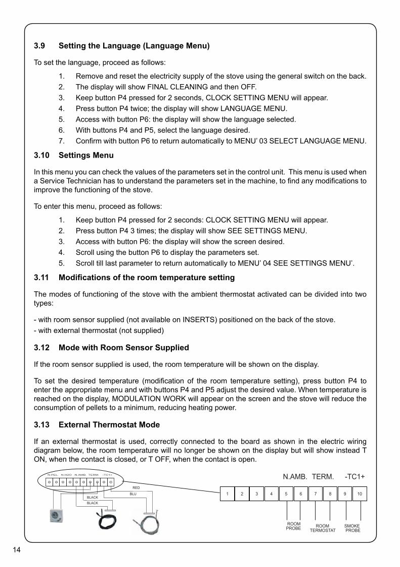
3.13 External Thermostat Mode
If an external thermostat is used, correctly connected to the board as shown in the electric wiring diagram below, the room temperature will no longer be shown on the display but will show instead T ON, when the contact is closed, or T OFF, when the contact is open.
1 2 3 5 6 7 8 9 104
-TC1+TERM.N.AMB.
SMOKE PROBE
ROOMTERMOSTAT
ROOM PROBE
-TC1+TERM.N.AMB.N.H2ON.PEL.
RossoBluNero
NeroBLACKBLACK
RED
BLU

15
REMARK: TO ACTIVATE THE OUTER THERMOSTAT, PRESS BUTTON P4 AND THEN REPEATEDLY ON P1 TILL YOU REACH THE SETTING “EST“ ON THE DISPLAY. CONFIRM WITH BUTTON P7.
The room temperature will be regulated directly by the wall-mounted thermostat. When the temperature set is reached, the display will show MODULATION WORK: the stove will work then at lower power to reduce the consumptionof the pellet.
3.14 Stove Status Menu
In this menu, you can check the correct functioning of the most important components of the pellet stove.
To enter this menu, proceed as follows:1. Keep button P4 pressed for 2 seconds, CLOCK SETTING MENU will appear.2. Press button P4 4 times: the display will show STOVE STATUS MENU.3. Access using button P6: the display will show the desired screen.4. Confirm with button P6 to return automatically to MENU’ 05 STOVE STATUS. This menu
is for use by a service technician to diagnose performance issues and for the customer when loading pellets into the pellet hopper when the stove has been completely run out of fuel.
3.15 Working Hours Menu
The WORKING HOURS Menu shows the total hours of work done by the stove. In some cases, the working hours may not be zeroed. i.e. numbers similar to 5000/15000/25000 may be shown. The technician will zero set these numbers when lighting the stove for the first time. A non-zero number does not mean that the stove has worked for all those hours. It is only a setting given by the programme during first inspection at Ecoteck, before the stoves are packaged and sent.
To enter this menu, proceed as follows:
1. Keep button P4 pressed for 2 seconds: CLOCK SETTING MENU will appear.2. Press button P4 5 times: the display will show WORKING HOURS MENU.3. Access with button P6: the display will show the screen desired.4. Confirm with button P6 to return automatically to MENU’ 06 WORKING HOURS MENU’.
MOTOR RPM
TEMPERATURE OF SMOKE STATE OF SCREW
2000130°CSCREW 0
STATE

16
3.16 Description of Screen Displays
3.17 Description of Alarms
SCREEN DISPLAY DESCRIPTION
FINAL CLEANING The stove is switching off, the cooling phase is not yet completed
ON The ignition phase has started,the pellets are loaded into fire pot
WAITING FOR FLAME The pellet’s are ignited by the hot air passing through the ignition candle
FLAME PRESENT The flame is visibile in the fire pot
WORKING The stove has completed the switch ON phase; you can now change the power
MODULATION WORKING The set room temperature has been reached
T ON The room sensor is off or an external thermostat has been connected
COOLING/WAITING FOR START The stove is cooling DOWN. When stove has cooled down it will start automatically.
ON/WAITING FOR RESTART The switch ON phase, when the stove is warm, started. The operation is same of phase ON
HOT SMOKE The max temperature of smokes is reached: to reduce temperature, feeding pellets and air draft reduce at POWER 01
OFF The stove is off
IMPORTANT IF DISPLAY SHOWS “HOT SMOKE“ THERE CAN BE PROBLEMS IN THE COMBUSTION OF PELLETS. PLEASE CONTACT A SERVICE TECHNICIAN.
WARNING REASON SOLUTION
PELLETS FINISHED ALARM
• The pellet hopper is empty • Check whether there are pellets in the hopper and refill if necessary.
• The raio-motor does not load pellets.
• Empty the hopper to check that no foreign objects have fallen inside which could prevent the correct functioning of the auger.
• Pellets not loading. • Regulate the pellet setting.
• IF THE PROBLEM CONTINUES, CONTACT YOUR LOCAL SERVICE TECHNICIAN.
BLACK - OUT
• No electricity supply during working phase. • Press the off button and repeat switching on the stove.
• IF THE PROBLEM CONTINUES, CONTACT YOUR LOCAL SERVICE TECHNICIAN.
NO IGNITION ALARM
• The pellet hopper is empty • Check whether there are pellets in the hopper and refill if necessary.
• Setting of pellets and of intake during ignition phase insufficient • Contact local Service Technician
• The resistance for lighting is defective or not in position • Contact local Service Technician
LOW FLAME ALARM• The pellet hopper is empty • Check whether there are pellets in the hopper and refill if
necessary.
• Bad setting of pellet and air during ignition • Contact local Service Technician
FAN RPM ALARM• The revolution of smoke fan
lowering more than 15% of speed to fan congestion
• Contact local Service Technician
17
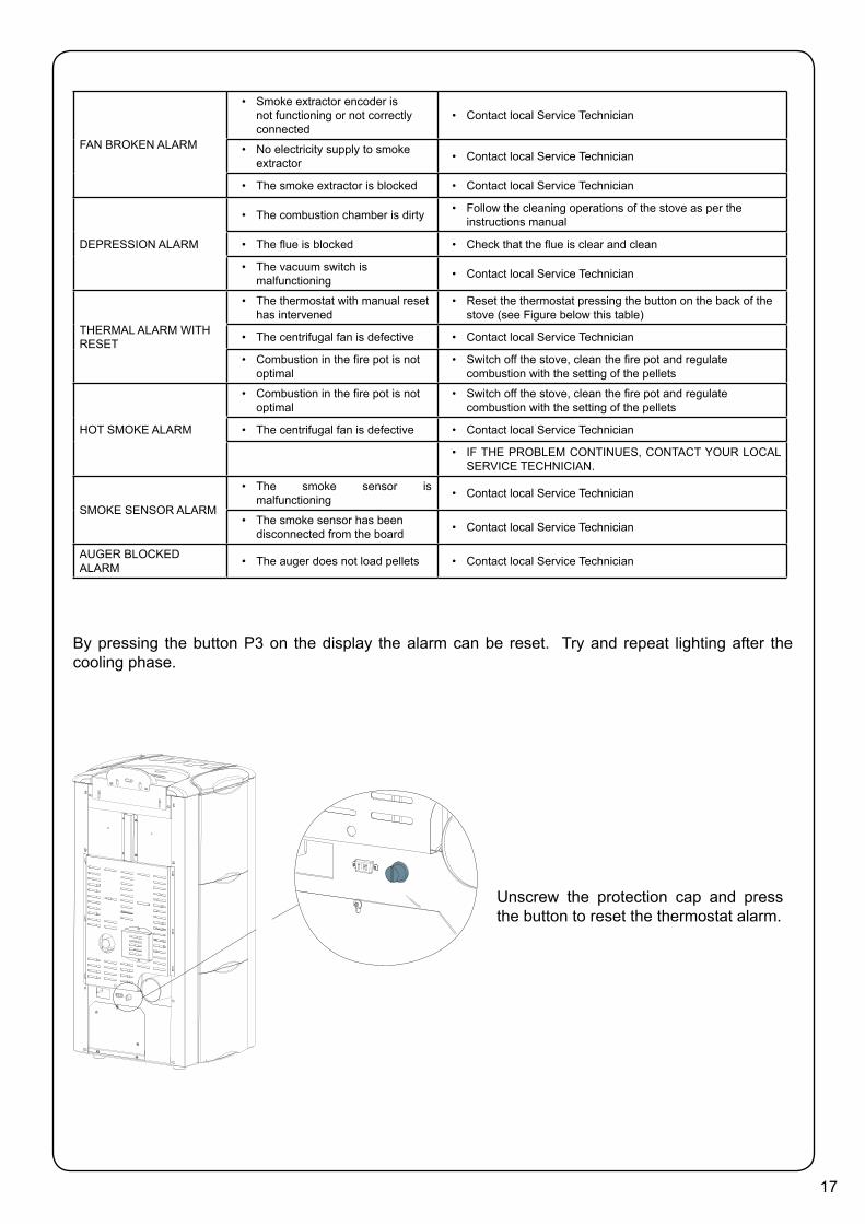
By pressing the button P3 on the display the alarm can be reset. Try and repeat lighting after the cooling phase.
FAN BROKEN ALARM
• Smoke extractor encoder is not functioning or not correctly connected
• Contact local Service Technician
• No electricity supply to smoke extractor • Contact local Service Technician
• The smoke extractor is blocked • Contact local Service Technician
DEPRESSION ALARM
• The combustion chamber is dirty • Follow the cleaning operations of the stove as per the instructions manual
• The flue is blocked • Check that the flue is clear and clean
• The vacuum switch is malfunctioning • Contact local Service Technician
THERMAL ALARM WITH RESET
• The thermostat with manual reset has intervened
• Reset the thermostat pressing the button on the back of the stove (see Figure below this table)
• The centrifugal fan is defective • Contact local Service Technician
• Combustion in the fire pot is not optimal
• Switch off the stove, clean the fire pot and regulate combustion with the setting of the pellets
HOT SMOKE ALARM
• Combustion in the fire pot is not optimal
• Switch off the stove, clean the fire pot and regulate combustion with the setting of the pellets
• The centrifugal fan is defective • Contact local Service Technician
• IF THE PROBLEM CONTINUES, CONTACT YOUR LOCAL SERVICE TECHNICIAN.
SMOKE SENSOR ALARM
• The smoke sensor is malfunctioning • Contact local Service Technician
• The smoke sensor has been disconnected from the board • Contact local Service Technician
AUGER BLOCKED ALARM • The auger does not load pellets • Contact local Service Technician
Unscrew the protection cap and press the button to reset the thermostat alarm.

18
4. Maintenance and CleaningBefore carrying out any maintenance take the following precautions:
• Make sure that the fire has been turned off, and that the general power supply has been disconnected (Ensure that the plug is disconnected from the socket, thus avoiding accidental electric shocks).
• Make sure that all parts of the pellet heater are cold.
• Make sure that the ashes have cooled completely.
• Make sure that the general switch is in the zero position (off).
• Always use appropriate tools for maintenance.
• When you have finished re-install all safety guards before using the pellet heater again.
The pellet heater requires little maintenance if quality wood pellets are used which is why we recommend pellet fuel that is manufactured to the AS/NZS4014.6.
4.1 Cleaning the surfaces
To clean the surfaces on the painted metal parts, use a damp cloth.
Important: the use of aggressive detergents or abrasive cleaners can damage the surfaces of the stove.
4.2 Cleaning the fire pot before and after each lighting
You must check that the fire pot, where the combustion takes place, is clean and that no waste or residue blocks the holes, in order to always guarantee excellent combustion of the stove. This will help avoid possible overheating, which could causes changes in the colour of the paint, as well as failure to light the stove.
Only a clean fire pot can guarantee that the pellet stove will function without problems. During functioning, deposits may be formed, which have to be immediately eliminated. It is easy to see when the fire pot has to be cleaned! It only needs a glimpse, each day, before switching on. For minor cleaning, it can be left in the stove, but if the residue is difficult to remove, it has to be extracted from its housing and the waste scraped out.
The residue of ash depends on the quality of pellets used.
Important: even with a new batch of pellets, although using the same brand, there may be differences during combustion and therefore they may burn more or less cleanly.
Correct daily cleaning will allow the pellet heater to burn properly with high performance avoiding problems in the long term which could require the intervention of a technician to repair the pellet heater.
Clean basket with all theholes clearly visible
Basket needing cleaning withthe holes blocked by ashes

19
4.3 Cleaning the FIREX 600
All Ecoteck products have a combustion chamber made with FIREX 600, a material based on vermiculite, the result of research and development by Ecoteck. The main features of FIREX 600 is its resistant to heat, its lightness and its excellent insulating capacities, which improve the combustion and performance of the stove. During combustion, FIREX 600 turns white, due to an effect called PYROLYSIS, making the flame clear and shining. If the combustion is regulated in an optimal way, the
FIREX 600 interior always remains clean and white.
The appearance and condition of the FIREX 600 is therefore an indicator of whether the combustion is good or not.
FIREX 600 LIGHT – EXCELLENT COMBUSTION
FIREX 600 DARK – POOR COMBUSTION
Combustion chamber
Fire pot
Ashes drawer
Fire pot grill
Scraper
20
Firex 600 does not require special maintenance, it only has to be dusted with a brush to remove the ash that is deposited during combustion.
Abrasive sponges to clean the most resistant waste should not be used as they could compromise the thickness of the FIREX600 panel, creating critical points of breakage.
The tube of the vacuum cleaner should not be used in direct contact with FIREX 600.
Wet cloths should not be used to clean FIREX 600.
FIREX 600 is resistant to heat but not to knocks; handle with care if moved.
FIREX 600 may show a slight abrasion after a few hours of functioning, this is perfectly normal as the flame creates microgrooves in the panel without compromising it. The duration of FIREX 600 depends only on how maintenance is carried out.
The pellet stove is a generator of heat with a solid fuel and as such requires servicing by qualified personnel at least once a year at the start of the season. This maintenance has the purpose of ascertaining and ensuring the efficiency and safety of all the components.
We recommend you draw up an annual contract for maintenance of the product with your installer/dealer.
4.4 Cleaning the combustion chamber
The stove requires simple but frequent cleaning to guarantee an efficient yield and correct functioning. Therefore, clean the combustion chamber every day using a drum-type vacuum cleaner, making sure that the ashes are cold first.
4.5 Cleaning the Flue
The flue will require cleaning only once each winter providing that the correct fuel is used. You should arrange for this when booking your annual service with your local Nature’s Flame service agent. Use a drum type vacuum cleaner only.

21
4.6 Access to the inspection hatches for cleaning the smoke
Remove the pellet heater and release the two screws that secure the hatches to the body of the pellet heater. Clean the inside using a drum type vacuum cleaner.
4.7 Frequency of Component Cleaning
INSPECTION HATCH (2 ON THE RIGHT SIDE)
INSPECTION HATCH(1 ON THE LEFT SIDE)
GASKET
GASKET
GASKET
SCRAPER
Parts/Frequency 1 Day 2-3 Days 30 Days Yearly Performed ByBurn pot • OwnerBurn pot grill • OwnerGlass • OwnerFlu • TechnicianDoor gasket • TechnicianHeat Exchanger • OwnerCombustion chamber • OwnerVacuum Hopper • OwnerClean T discharge • Technician

22
4.8 Cleaning the Ashes Draw
The ashes drawer must be cleaned every 2 days, depending on the length of time the stove is used and the type of pellet used. To access the drawer, open the door (see figure 1) and extract the ashes drawer (see figure 2).
N.B.: The operation must be carried out when the stove is cold, using a drum-type vacuum cleaner.
HOW TO REMOVE THE FLAME TRAP:N.B.: REMOVE AND CLEAN THE FLAME TRAP REGULARLY.
1 2
FRONT FLAME TRAP REST
REAR FLAME TRAP REST
Phase B
Phase A
POSITION OF THE FRAME TRAP
SLOT
23
5. Guarantee5.1 Certificate of Guarantee
Ecoteck thanks you for the confidence you have placed in it with the purchase of one of our pellet stoves and invites the purchaser to:
- examine the instructions for the installation, use and maintenance of the stove.
- examine the conditions of guarantee shown below.
The form provided by the installer must be filled in and stamped by the installer. If this does not occur, the product will not be covered by the guarantee.
5.2 Conditions of Guarantee
The limited guarantee covers defects of manufacturing materials, on condition that the product has not been broken due to an incorrect use, carelessness, wrong connections or errors of installation.
The following are not covered by guarantee:
- vermiculite (Firex 600);
- the glass of the door;
- the fibre gaskets;
- the painting;
- the stainless steel combustion basket;
- the resistance;
- the cast majolica
- any damage caused by inappropriate installation and/or handling of the stove and/or shortcomings by the consumer.
The use of poor quality pellets or of any other material could damage components of the stove causing the termination of their guarantee and the annexed responsibility of the manufacturer.
All damage caused by transport are not acknowledged, therefore please carefully check the goods on receipt, immediately advising the dealer of any damage.
The guarantee form must be sent to the following address within eight days of purchase:
Nature’s FlamePO Box 11-043SockburnChristchurch 8443

24
6. What are Wood Pellets?Wood pellets are made from sawdust and wood shavings. The material used cannot contain any foreign substance such as glue, varnish or synthetic substances. Subjecting it to high pressure, the wood is pressed through a plate with holes and due to the high pressure the sawdust is heated activating the natural binders of the wood. Thus, the pellets keep their shape even without the addition of bonding substances. The density of the wood pellet varies according to the type of wood and can be 1.5 – twice greater than that of natural wood. The diameter of the cylindrical rods is 6-10 mm and their length can vary between 10 and 50 mm. Their weight is equal to about 650 kg/m. Due to the low content of water (approx 8%) they have a high energy content. The standards AS/NZS4014.6 define the quality of the pellets:
Do not put the bag of pellets on the ceramic parts during the loading operations.
The pellets must be transported and stored in a dry place. They swell on contact with damp, and cannot be used, They must always be protected from the damp both during transport and in storage. Ecoteck recommends using a pellet with a diameter of 6 mm for the stove.
7. The Components of the Stove
7
23
6
1
8
9
5
4
9
1. Pellet loading screw2. Resistance unit for ignition3. Combustion fire pot4. Tube for passage of smoke5. Air intake tube (optional)6. Stainless steel exchanger7. Pellet hopper8. Flame trap9. Smoke exhaust tube
This drawing shows the internal parts of a pellet stove. By filling the tank (7), the pellets are loaded into the fire pot (3) through the loading screw (1). Ignition is by means of the resistance (2), which overheats the air from the special entrance (5) which on contact with the pellets will allow the development of the flame. At this point the exhaust smoke is deviated towards the stainless steel exchanger (6) and through the smoke extraction tube (4) it is released into the flue, through the connection with the smoke exhaust pipe. (9).

25
Installation Section
Table of Contents
1. Dimensions (Ecoteck Monica Plus) ...............................................261.1 Deciding where to locate your wood pellet burning heater: ...........................271.2 Clearances to Combustibles – Ecoteck Monica Plus Freestanding ..............271.3 Exhaust and Fresh Air Intake Locations ...........................................................28
2. Installation ............................................................................292.1 Dimensions – Monica Plus Freestanding .........................................................292.2 Clearances & Specifications ..............................................................................292.3 Minimum Clearance to Combustibles ...............................................................302.4 Location of the Pellet Fire ..................................................................................302.5 Positioning the fire: ............................................................................................302.6 Location of a power source ...............................................................................302.7 Internal Standard Flue Kit (50) ...........................................................................312.8 External Standard Flue Kit (51) ..........................................................................322.9 Seismic Restraint ................................................................................................332.10 Fixing to Timber Floor Framing .........................................................................332.11 Installation ...........................................................................................................332.12 How to remove the side panels .........................................................................342.13 Seismic Restraint Locations ..............................................................................35
3. Installation Data Sheet ....................................................................364. Maintenance Record .......................................................................37
NOTE TO INSTALLER - PLEASE ENSURE THE “INSTALLATION DATA SHEET” ON PAGE 36 IS COMPLETED ONCE THE UNIT IS INSTALLED.

26
1. Dimensions (Ecoteck Monica Plus)
The data shown above are indicative and not binding. Ecoteck reserves the right to make any modifications for the purpose of improving the performances of the product.
Unit of Measurement
Height mm 1037
Width mm 508
Depth mm 476
Weight Kg 130
Diameter of smoke exhaust duct mm 80
Min.-max. calorific power kW 5.0 - 6.5
Min.-max. hourly consump-tion of pellets Kg/h 0.99 – 1.43
Electrical power absorbed during operation W 240
Supply V - Hz 220 – 50
Tank capacity Kg 15
Space Heating Efficiency % 85.0
771m
m30
,33i
n
385m
m15
,16i
n 190mm7,48in
599m
m23
,59i
n
43mm1,69in
459mm18,07in
1037
mm
40,8
1in
1000
mm
39,3
6in
27
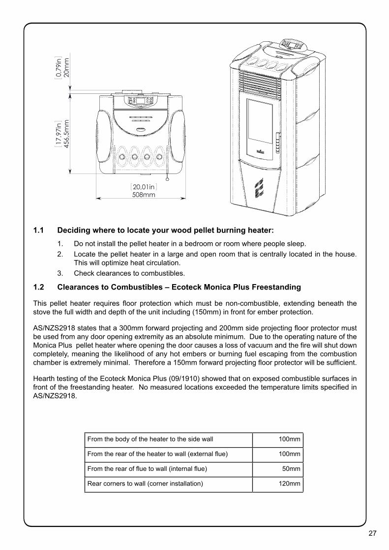
1.1 Deciding where to locate your wood pellet burning heater:1. Do not install the pellet heater in a bedroom or room where people sleep.2. Locate the pellet heater in a large and open room that is centrally located in the house.
This will optimize heat circulation.3. Check clearances to combustibles.
1.2 Clearances to Combustibles – Ecoteck Monica Plus Freestanding
This pellet heater requires floor protection which must be non-combustible, extending beneath the stove the full width and depth of the unit including (150mm) in front for ember protection.
AS/NZS2918 states that a 300mm forward projecting and 200mm side projecting floor protector must be used from any door opening extremity as an absolute minimum. Due to the operating nature of the Monica Plus pellet heater where opening the door causes a loss of vacuum and the fire will shut down completely, meaning the likelihood of any hot embers or burning fuel escaping from the combustion chamber is extremely minimal. Therefore a 150mm forward projecting floor protector will be sufficient.
Hearth testing of the Ecoteck Monica Plus (09/1910) showed that on exposed combustible surfaces in front of the freestanding heater. No measured locations exceeded the temperature limits specified in AS/NZS2918.
From the body of the heater to the side wall 100mm
From the rear of the heater to wall (external flue) 100mm
From the rear of flue to wall (internal flue) 50mm
Rear corners to wall (corner installation) 120mm
456,
5mm
17,9
7in
20m
m0,
79in
508mm20,01in

28
1.3 Exhaust and Fresh Air Intake Locations
Exhaust Insert
Hearth to centre of flue 326mm
Side of unit to centre of flue 115mm
Centre of unit to centre of flue 137mm
Fresh Air Intake
Hearth to centre of intake 356mm
Side of unit to centre of intake 169mm
Centre of unit to center of intake 83mm
INSTALL VENT AT CLEARANCES SPECIFIED BY THE VENTING MANUFACTURER
80m
m3,
13in
83mm3,27in
103mm4,06in
278m
m10
,94i
n
418m
m16
,45i
n
35m
m1,
38in

29
2. Installation2.1 Dimensions – Monica Plus Freestanding
771m
m30
,33i
n
385m
m15
,16i
n 190mm7,48in
599m
m23
,59i
n
43mm1,69in
459mm18,07in
1037
mm
40,8
1in
1000
mm
39,3
6in
456,
5mm
17,9
7in
20m
m0,
79in
508mm20,01in
Refer to Safety Test 09/1910 for all clearances to combustible.
2.2 Clearances & Specifications
Minimum clearances shown are in millimetres. All Ecoteck fires are tested to AS/NZS2918:2001. Specifications were correct at time of printing but may alter and those detailed below should be used as a guide only. Refer to the Installation and Operation Manual supplied with every Ecoteck Pellet Fire or if in doubt, consult your Nature’s Flame Retailer.
B
J
H
AE
External Flue
J
J
F
B
I F
E
Monica Plus Pellet FireClearance to Combustibles
B
C
A E
D
G
F
B
FG
E
Internal Flue
Location Dimension (mm)
A 50
B 150
C* 50
D 230
E 100
F 120
G* 50
H 50
I* 50
J* 25
Freestanding Clearances
* from shielded fl ueNote: AS/NZS 2918 requires a minimum of 100mm clearance for any side requiring access.Note: These are minimum clearances to combustibles. Actual installation distances may be greater.
Note: The above clearance to combustibles on the fl ue are only applicable within the fi re envelope. Clearance outside this e.g.at a ceiling / wall thimble reverts to 25mm as per ARS fl ue test 05/1185.

30
Side of Unit (B) 100mmRear wall to Lined Flue (D, L, J) 50mmRear wall to Unlined Flu (D, L, J) 75mmRear of Unit (M) 100mmRear corners (Corner Installation) (G) 120mmFloor protection (from glass) (C) 150mm
2.3 Minimum Clearance to Combustibles
2.4 Location of the Pellet Fire
Installation of the Ecoteck Monica Plus Freestanding Wood Pellet Burning Heater should be undertaken by an experienced installer. Please read the Monica Plus Owners/Technical Manual thoroughly before commencing installation as failure to follow the instruction could cause damage to the pellet fire or property.
2.5 Positioning the fire:
Generally Monica Plus should be installed in a centrally located position within the home. When deciding where to position the appliance in your room you need to consider the following:
2.6 Location of a power source
• Monica Plus has a convection fan which blows air through tubes in the direction that the fire faces, for optimum performance this location should be in a large room centrally located.
• Monica Plus must be installed on a non-combustible surface. This surface must protrude 150mm from the front of the closed pellet fire door.
• Monica Plus has been Safety Tested to AS/NZS 2918 using the Davins manufactured flue. Test Report ARS 05/1185. Installation is not exclusive to these nominated kits, though alternative flue should only be considered following consultation with your local council.
• Please consult page 30 for the required clearances to combustible material also ensure the position of structural elements near the proposed flue.
• Because of the positive pressure in the flue, sealing of all 75mm stainless joints is mandatory – use high temperature Maniseal. Both inner and outer flue joints must be riveted.
• Seismic Restraint: Please view page 33 for requirements.
• Warranty: To validate warranty following installation a copy of the completed Warranty/Producers Statement must be forwarded to: Nature’s Flame- Fax (03) 348 1743.

31
2.7 Internal Standard Flue Kit (50)Internal Standard Flue Kit
Each 50 Internal Standard Flue Kit contains:-
ytitnauQnoitpircseDoN traP
1 Galvanised outer linerø100mm x 900mm long 1
4
3
2
1
1
1
1
1
1
2
2 Stainless steel inner linerø75mm x 900mm long
4a Black p/coat outer linerø100mm x 900mm long
5 Inner/outer �ue liner spacer
6c Ceiling thimble ø107mm hole
7c Ceiling decor plateø107mm hole – white
8 Rain cap 75mm
9 Rain Cap 100mm
10b Elbow 45° – ø75mm stainless– black (painted)
12H T-adaptor/cleanout – ø75mm– black (painted)
23 Support angle 950mm long– 50mm x 50mm sides
This �ue kit may be used in new and replacementapplications in rooms with stud height of 2.4m. Theoverall height of the �ue is 3.6m. The visible �u e is�nished in black and the ceiling plate is white. T hesupport angles for securing the liner to the ceilin g arenot shown. Kit is supplied in a carton.
Heat-resistant�oor protector
Seismic restraint(to be �tted)
50mm minimum clearance if lined �ue
600mm fromroof
penetration
~210 mm
150mm (minimum)
Note: The Davin 50 Internal Standard FlueKit complies with AS/NZS 2918:2001 as perApplied Research Test Report 05/1185, dated15 September 2005. All �res must be installed by a quali�edinstaller as per the manufacturer’sinstructions and AS/NZS2918:2001.
50
To order : Telephone 0800 765 431. Fax 64 3 341 8057 [email protected] www.switchenergy.co.nzDecember 2006
Drawing representative only - not to scale.
This flue kit may be used in new and replacement applications in rooms with stud height of 2.4m. The overall height of the flue is 3.6m. The visible flue is finished in black and the ceiling plate is white. The support angles for securing the liner to the ceiling are not shown. Kit is supplied in carton.

32
2.8 External Standard Flue Kit (51)
Each 51 External Standard Flue Kit contains:-
ytitnauQnoitpircseDoN traP
1 Galvanised outer linerø100mm x 900mm long
2 Stainless steel inner linerø75mm x 900mm long
5 Inner/outer �ue liner spacer
6w Wall thimble – 2 piecesø102mm holes
6s So�t thimble ø107mm hole
7w Wall decor plateø102mm hole – white
8 Rain cap 75mm
9 Rain Cap 100mm
26 Lined T-adaptor
This �ue kit may be used in new and replacementapplications with the �ue penetrating the wall behindthe �re, running vertically up an outside wall andpenetrating the so�t. The overall height of the f lue is3.6m. All visible �ue has a galvanised �nish, and can bepowdercoated on request. Kit is supplied in a carton.
Note: The Davin 51 External Standard FlueKit complies with AS/NZS 2918:2001 as perApplied Research Test Report 05/1185, dated15 September 2005. All �res must be installed by a quali�edinstaller as per the manufacturer’sinstructions and AS/NZS2918:2001.
Heat-resistant�oor protector
Seismic restraint(to be �tted)
600mm fromroof penetration
100mm (minimum)
150mm (minimum)
External Standard Flue Kit51
4
4
2
1
1
1
1
1
1
To order :December 2006 Telephone 0800 765 431. Fax 64 3 341 8057 [email protected] www.switchenergy.co.nz
Drawing representative only - not to scale.
This flue kit may be used in new and replacement applications with the flue penetrating the wall behind the fire, running vertically up an outside wall and penetrating the soffit. The overall height of the flue is 3.6m. All visible flue has a galvanised finish, and can be powdercoated on request. Kit is supplied in a carton.
33
2.9 Seismic Restraint
All installation scenarios for Monica Plus require the use of hold-down anchors (one on each side).
Fixing to Concrete Floor:
• Minimum M8 expansion anchors (M10 recommended) or min M8 epoxy- set anchors.
• Approved Anchors: Expansion Anchors-Ramset Dynabolt and Trubolt, Hilti HAS.
• Epoxy-set Anchors – Ramset Epcon, Ramset Chemset and Hilti HVU.
2.10 Fixing to Timber Floor Framing
Minimum 14g x 60 screws (6.3mm diameter) or M10 X 90 coach-screws. These shall be fixed a minimum of 40mm into the centre-line of the existing floor joists. If screws cannot be installed directly into an existing floor joist, solid blocking between joists (min size 90x45) shall be provided.
2.11 Installation
Monica Plus should be installed in a centrally located position within the home. This will assist the appliance to perform to the level required. As Monica Plus heats space by convecting air through heat exchange tubes, the heater should face the area the majority of the area to be heated.
Monica Plus requires a power source to function. This is standard mains feed 240v plug-if this is unavailable in close proximity a grounded extension lead may be used.
Monica Plus is to be installed on a non-combustible surface which must have a forward projection of a minimum of 150mm from the glass door.
Ensure all 75mm flue joins are sealed with a high temp silicon (Maniseal).
Please check all clearances to combustibles as listed on page 30 of this Owners’/Technical manual.
In accordance with the requirements of AS/NZS 2918:2001 Monica Plus must be secured by seismic restraint.

34
2.12 How to mount the ceramic side panels.
Remove the 2 screws on the top of the backof the stove and remove the pellet lid .
SPACERS
SPACERS
Insert the ceramic tiles in the side guide, insertingthe rubber spacers as illustrated in the figure.Mount the ceramic top on the top of the stove;
To adjust the height of the top adjust the four screws; makesure that the screws have their rubber cap. At the end,
remount to the pellet lid.
Rubber Cap

35
2.13 Seismic Restraint Locations
INSPECTION HATCH(2 ON THE RIGHT SIDE)
GASKET
GASKET
INSPECTION HATCH (1 ON THE LEFT SIDE)
SEISMIC RESTRAINT LOCATION
SEISMIC RESTRAINT LOCATION

36
3. Installation Data Sheet
Name of Owner:
________________________________
Address:
________________________________
________________________________
________________________________
________________________________
Phone:
________________________________
Name of Dealer:
________________________________
Address:
________________________________
________________________________
________________________________
________________________________
Phone:
________________________________
Model: __________________________
Serial Number: ____________________
Date of Purchase: __________ (dd/mm/yy)
Date of Installation: _________ (dd/mm/yy)
Magnehelic at Install: _______________
Installer’s Signature:
________________________________
Name of Installer:
________________________________
Address:
________________________________
________________________________
________________________________
________________________________
Phone:
________________________________
WARRANTY: If you have concerns with your unit please contact the dealer where you purchased the stove.

37
4. Maintenance Record
DATE WORK CARRIED OUT SIGNATURE