Deerfield Pellet Stove - Travis Industriesinstallation and use of this pellet fuel-burning room...
52
Deerfield Pellet Stove • Horizontal or Vertical Vent • Freestanding Stove • Mobile Home Approved • Class A Chimney Retrofit • Hearth Stove into Existing Masonry Chimney , Masonry Fireplace, or Z.C. Fireplace -- Please read this entire manual before installation and use of this pellet fuel- burning room heater. Failure to follow these instructions could result in property damage, bodily injury, or even death. -- Contact local building or fire officials about restrictions and installation inspection requirements in your area. -- Save these instructions. Tested and Listed by: ASTM E1509-12 ULC-S627 Installer: After installation give this manual to the home- owner and explain operation of this heater. Consumer: Retain this manual for future reference. $10.00 Copyright 2018, T.I. Part # 100-01445 2/18/19 www.travisproducts.com 12521 Harbour Reach Drive SW Mukilteo, WA 98275
Transcript of Deerfield Pellet Stove - Travis Industriesinstallation and use of this pellet fuel-burning room...
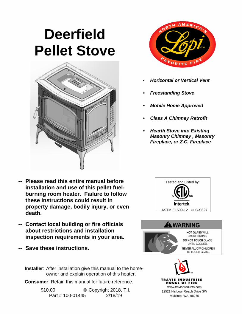
Deerfield Pellet Stove
• Horizontal or Vertical Vent
• Freestanding Stove
• Mobile Home Approved
• Class A Chimney Retrofit
• Hearth Stove into Existing Masonry Chimney , Masonry Fireplace, or Z.C. Fireplace
-- Please read this entire manual before installation and use of this pellet fuel-burning room heater. Failure to follow these instructions could result in property damage, bodily injury, or even death.
-- Contact local building or fire officials about restrictions and installation inspection requirements in your area.
-- Save these instructions.
Tested and Listed by:
ASTM E1509-12 ULC-S627
Installer: After installation give this manual to the home-owner and explain operation of this heater.
Consumer: Retain this manual for future reference.
$10.00 Copyright 2018, T.I. Part # 100-01445 2/18/19
www.travisproducts.com
12521 Harbour Reach Drive SW Mukilteo, WA 98275
2 Introduction
© Travis Industries 2/18/19 - 1445 Deerfield Stove
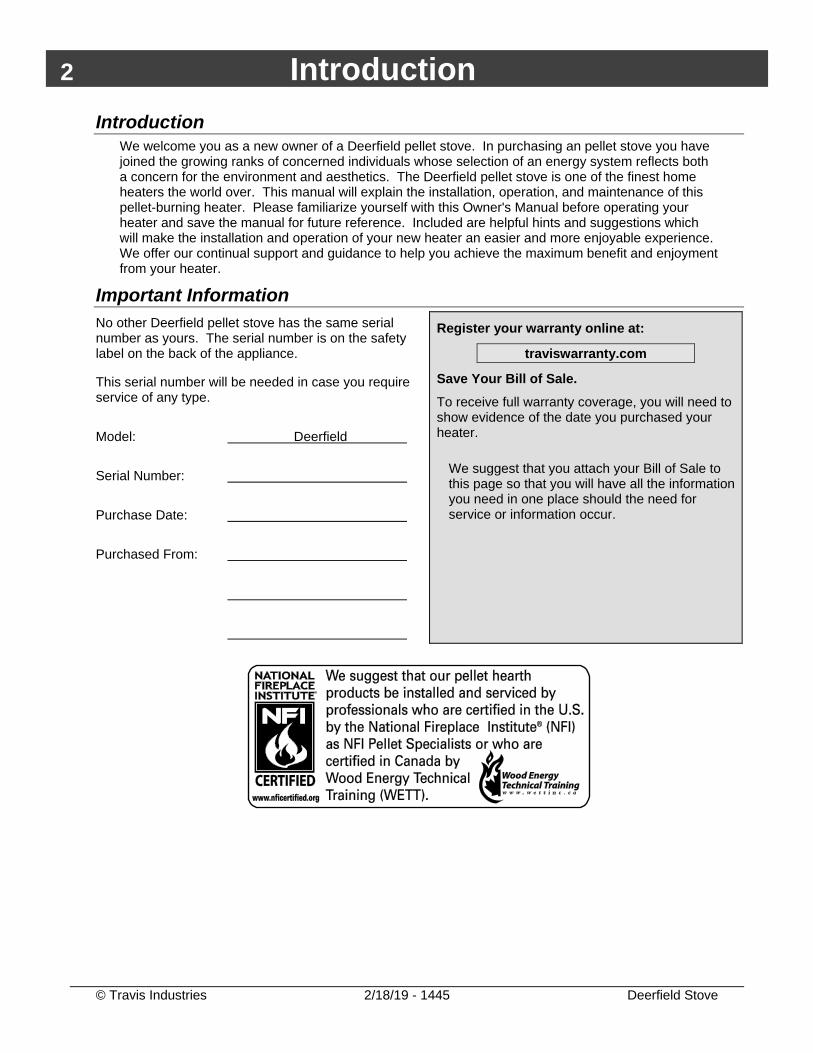
Introduction We welcome you as a new owner of a Deerfield pellet stove. In purchasing an pellet stove you have joined the growing ranks of concerned individuals whose selection of an energy system reflects both a concern for the environment and aesthetics. The Deerfield pellet stove is one of the finest home heaters the world over. This manual will explain the installation, operation, and maintenance of this pellet-burning heater. Please familiarize yourself with this Owner's Manual before operating your heater and save the manual for future reference. Included are helpful hints and suggestions which will make the installation and operation of your new heater an easier and more enjoyable experience. We offer our continual support and guidance to help you achieve the maximum benefit and enjoyment from your heater.
Important Information No other Deerfield pellet stove has the same serial number as yours. The serial number is on the safety label on the back of the appliance. This serial number will be needed in case you require service of any type. Model: Deerfield Serial Number: Purchase Date: Purchased From:
Register your warranty online at:
traviswarranty.com
Save Your Bill of Sale. To receive full warranty coverage, you will need to show evidence of the date you purchased your heater.
We suggest that you attach your Bill of Sale to this page so that you will have all the information you need in one place should the need for service or information occur.
Table of Contents 3
© Travis Industries 2/18/19 - 1445 Deerfield Stove
Introduction .............................................................. 2 Important Information .............................................. 2 Heating Specifications ............................................. 7 Dimensions ............................................................... 7 Electrical Specifications .......................................... 7 Fuel ............................................................................ 7 Emissions ................................................................. 7 Efficiency .................................................................. 7 Before You Begin ..................................................... 8 Packing List .............................................................. 8 Installation Options .................................................. 8 Planning the Installation .......................................... 9 Stove Placement ...................................................... 9 Floor Protection Requirements ............................... 9 Electrical Requirements .......................................... 9 Clearances .............................................................. 10
Straight Installations ............................................ 10 Corner Installations ............................................. 10
Venting the Pellet Stove ........................................ 11 Maximum Venting Distance ................................ 11 Pellet Vent Type .................................................. 12 Installing the Pellet Vent ..................................... 12 Pellet Vent Termination ....................................... 12
Mobile Home Requirements .................................. 13 Outside Air (Used for Combustion − Part #99200139) .............................................................. 13 Alcove Installation Requirements ......................... 14 Restrictor Adjustment ........................................... 14 External Thermostat Installation ............................ 15 Installation Examples ............................................ 16
Installation Example: Direct "Through-the-wall" Installation ........................................................... 16 Installation Example: Interior Vertical Installation 17 Class A Chimney Retrofit .................................... 18 Installation Example: Masonry Fireplace Hearth Stove ................................................................... 19 Installation Example: Zero-Clearance (Metal) Fireplace Hearth Stove ....................................... 20
Installation Example: Freestanding Masonry Chimney .............................................................. 21
Safety Notice .......................................................... 22 Touch Screen Controls .......................................... 22 Loading Pellets ....................................................... 23 Starting the Heater for the First Time ................... 23
Curing the Paint .................................................. 23 Modes of Operation – Manual or Thermostat ...... 24
Manual Mode .......................................................... 24 Thermostat Mode .................................................... 24
Manual Mode .......................................................... 25 To Start ................................................................... 25 To Shut Down ......................................................... 25
Adjusting the Heat Setting................................... 25 Thermostat (T-stat) Mode ...................................... 26 Fan Setting ............................................................. 28
Manual Adjustments ........................................... 28 Auto-Fan ............................................................. 28
Heater Status .......................................................... 29 Standby ............................................................... 29 Start-Up............................................................... 29 Heating ............................................................... 29 Cool-Down .......................................................... 29 Fault .................................................................... 29
Menu Button ........................................................... 30 T-Stat Temperature ............................................. 30 T-Stat Source ...................................................... 30 T-Stat Program ................................................... 30 Screen Lock ........................................................ 30
Power Outages ....................................................... 31 Manual Mode .......................................................... 31 TSTAT Mode ........................................................... 31
Normal Operating Sounds ..................................... 31 Stove Maintenance ................................................. 32 Monthly Maintenance (while appliance is in use) ... 41 Door Parts ............................................................... 46 Wiring Diagram ....................................................... 48
4 Safety Precautions
© Travis Industries 2/18/19 - 1445 Deerfield Stove
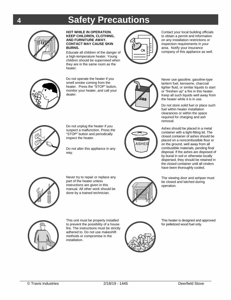
HOT WHILE IN OPERATION. KEEP CHILDREN, CLOTHING, AND FURNITURE AWAY. CONTACT MAY CAUSE SKIN BURNS. Educate all children of the danger of a high-temperature heater. Young children should be supervised when they are in the same room as the heater.
Contact your local building officials to obtain a permit and information on any installation restrictions or inspection requirements in your area. Notify your insurance company of this appliance as well.
Do not operate the heater if you smell smoke coming from the heater. Press the “STOP” button, monitor your heater, and call your dealer.
Never use gasoline, gasoline-type lantern fuel, kerosene, charcoal lighter fluid, or similar liquids to start or “freshen up” a fire in this heater. Keep all such liquids well away from the heater while it is in use.
Do not store solid fuel or place such fuel within heater installation clearances or within the space required for charging and ash removal.
Do not unplug the heater if you suspect a malfunction. Press the “STOP” button and periodically inspect the heater.
Do not alter this appliance in any way.
Ashes should be placed in a metal container with a tight-fitting lid. The closed container of ashes should be placed on a noncombustible floor or on the ground, well away from all combustible materials, pending final disposal. If the ashes are disposed of by burial in soil or otherwise locally dispersed, they should be retained in the closed container until all cinders have been thoroughly cooled.
Never try to repair or replace any part of the heater unless instructions are given in this manual. All other work should be done by a trained technician.
The viewing door and ashpan must be closed and latched during operation.
This unit must be properly installed to prevent the possibility of a house fire. The instructions must be strictly adhered to. Do not use makeshift methods or compromise in the installation.
This heater is designed and approved for pelletized wood fuel only.
Safety Precautions 5
© Travis Industries 2/18/19 - 1445 Deerfield Stove
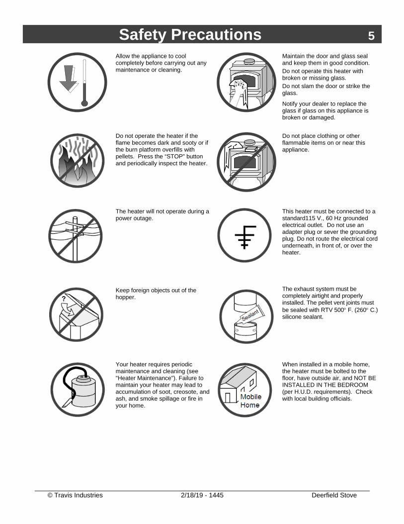
Allow the appliance to cool completely before carrying out any maintenance or cleaning.
Maintain the door and glass seal and keep them in good condition. Do not operate this heater with broken or missing glass. Do not slam the door or strike the glass.
Notify your dealer to replace the glass if glass on this appliance is broken or damaged.
Do not operate the heater if the flame becomes dark and sooty or if the burn platform overfills with pellets. Press the “STOP” button and periodically inspect the heater.
Do not place clothing or other flammable items on or near this appliance.
The heater will not operate during a power outage.
This heater must be connected to a standard115 V., 60 Hz grounded electrical outlet. Do not use an adapter plug or sever the grounding plug. Do not route the electrical cord underneath, in front of, or over the heater.
Keep foreign objects out of the hopper.
The exhaust system must be completely airtight and properly installed. The pellet vent joints must be sealed with RTV 500° F. (260° C.) silicone sealant.
Your heater requires periodic maintenance and cleaning (see "Heater Maintenance"). Failure to maintain your heater may lead to accumulation of soot, creosote, and ash, and smoke spillage or fire in your home.
When installed in a mobile home, the heater must be bolted to the floor, have outside air, and NOT BE INSTALLED IN THE BEDROOM (per H.U.D. requirements). Check with local building officials.
6 Safety Precautions
© Travis Industries 2/18/19 - 1445 Deerfield Stove
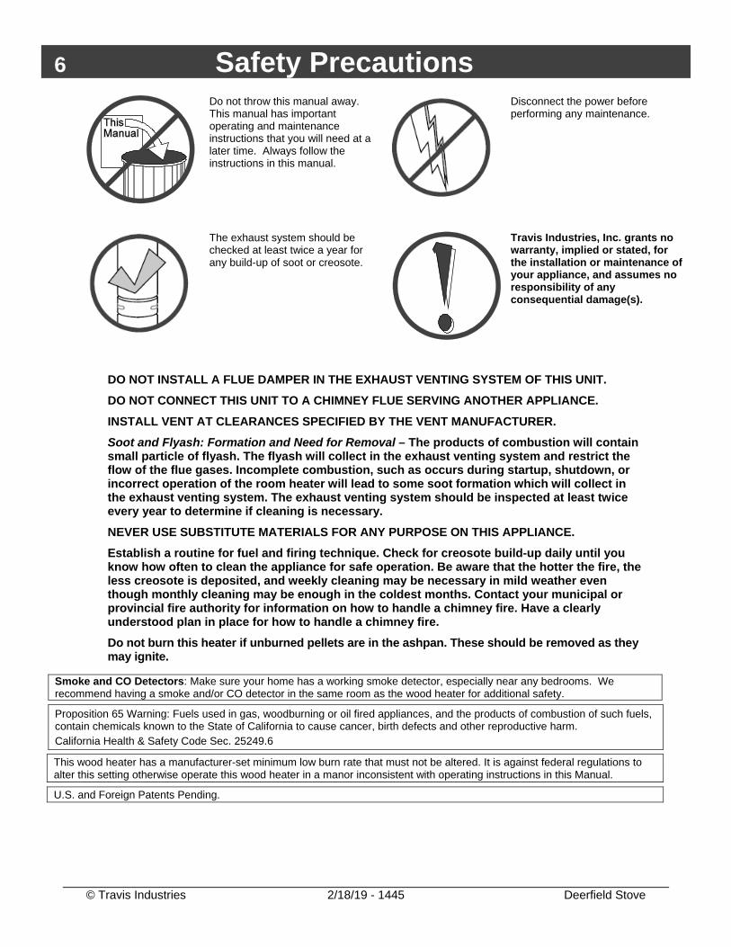
Do not throw this manual away. This manual has important operating and maintenance instructions that you will need at a later time. Always follow the instructions in this manual.
Disconnect the power before performing any maintenance.
The exhaust system should be checked at least twice a year for any build-up of soot or creosote.
Travis Industries, Inc. grants no warranty, implied or stated, for the installation or maintenance of your appliance, and assumes no responsibility of any consequential damage(s).
DO NOT INSTALL A FLUE DAMPER IN THE EXHAUST VENTING SYSTEM OF THIS UNIT. DO NOT CONNECT THIS UNIT TO A CHIMNEY FLUE SERVING ANOTHER APPLIANCE. INSTALL VENT AT CLEARANCES SPECIFIED BY THE VENT MANUFACTURER. Soot and Flyash: Formation and Need for Removal – The products of combustion will contain small particle of flyash. The flyash will collect in the exhaust venting system and restrict the flow of the flue gases. Incomplete combustion, such as occurs during startup, shutdown, or incorrect operation of the room heater will lead to some soot formation which will collect in the exhaust venting system. The exhaust venting system should be inspected at least twice every year to determine if cleaning is necessary. NEVER USE SUBSTITUTE MATERIALS FOR ANY PURPOSE ON THIS APPLIANCE. Establish a routine for fuel and firing technique. Check for creosote build-up daily until you know how often to clean the appliance for safe operation. Be aware that the hotter the fire, the less creosote is deposited, and weekly cleaning may be necessary in mild weather even though monthly cleaning may be enough in the coldest months. Contact your municipal or provincial fire authority for information on how to handle a chimney fire. Have a clearly understood plan in place for how to handle a chimney fire. Do not burn this heater if unburned pellets are in the ashpan. These should be removed as they may ignite.
Smoke and CO Detectors: Make sure your home has a working smoke detector, especially near any bedrooms. We recommend having a smoke and/or CO detector in the same room as the wood heater for additional safety.
Proposition 65 Warning: Fuels used in gas, woodburning or oil fired appliances, and the products of combustion of such fuels, contain chemicals known to the State of California to cause cancer, birth defects and other reproductive harm. California Health & Safety Code Sec. 25249.6
This wood heater has a manufacturer-set minimum low burn rate that must not be altered. It is against federal regulations to alter this setting otherwise operate this wood heater in a manor inconsistent with operating instructions in this Manual.
U.S. and Foreign Patents Pending.
Installation (For Qualified Installers Only) 7
© Travis Industries 2/18/19 - 1445 Deerfield Stove
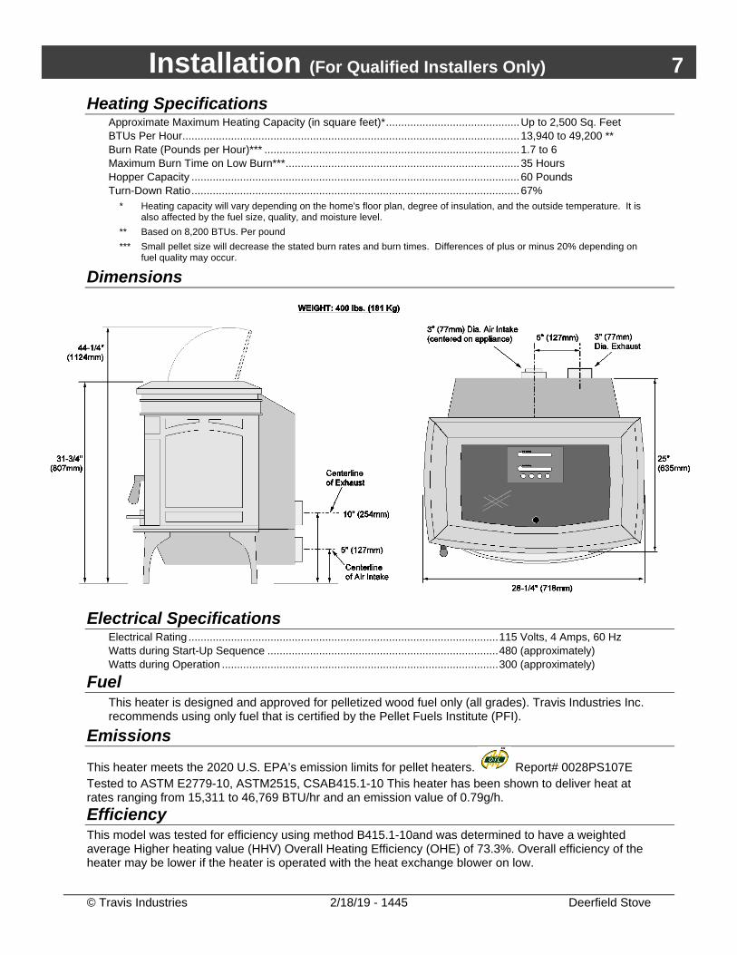
Heating Specifications Approximate Maximum Heating Capacity (in square feet)* ............................................ Up to 2,500 Sq. Feet BTUs Per Hour ............................................................................................................... 13,940 to 49,200 ** Burn Rate (Pounds per Hour)*** .................................................................................... 1.7 to 6 Maximum Burn Time on Low Burn*** ............................................................................. 35 Hours Hopper Capacity ............................................................................................................ 60 Pounds Turn-Down Ratio ............................................................................................................ 67%
* Heating capacity will vary depending on the home's floor plan, degree of insulation, and the outside temperature. It is also affected by the fuel size, quality, and moisture level.
** Based on 8,200 BTUs. Per pound *** Small pellet size will decrease the stated burn rates and burn times. Differences of plus or minus 20% depending on
fuel quality may occur.
Dimensions
Electrical Specifications Electrical Rating ...................................................................................................... 115 Volts, 4 Amps, 60 Hz Watts during Start-Up Sequence ............................................................................ 480 (approximately) Watts during Operation ........................................................................................... 300 (approximately)
Fuel This heater is designed and approved for pelletized wood fuel only (all grades). Travis Industries Inc. recommends using only fuel that is certified by the Pellet Fuels Institute (PFI).
Emissions
This heater meets the 2020 U.S. EPA’s emission limits for pellet heaters. Report# 0028PS107E Tested to ASTM E2779-10, ASTM2515, CSAB415.1-10 This heater has been shown to deliver heat at rates ranging from 15,311 to 46,769 BTU/hr and an emission value of 0.79g/h. Efficiency This model was tested for efficiency using method B415.1-10and was determined to have a weighted average Higher heating value (HHV) Overall Heating Efficiency (OHE) of 73.3%. Overall efficiency of the heater may be lower if the heater is operated with the heat exchange blower on low.
8 Installation (For Qualified Installers Only)
© Travis Industries 2/18/19 - 1445 Deerfield Stove
Before You Begin READ THIS ENTIRE MANUAL BEFORE YOU INSTALL AND USE THIS HEATER. FAILURE TO FOLLOW THE INSTRUCTIONS MAY RESULT IN PROPERTY DAMAGE, BODILY INJURY, OR EVEN DEATH. Check with local building officials for any permits required for installation of this pellet heater and notify your insurance company before proceeding with installation.
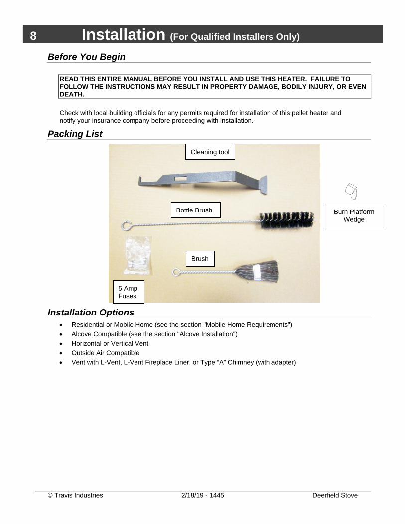
Packing List
Installation Options • Residential or Mobile Home (see the section "Mobile Home Requirements") • Alcove Compatible (see the section "Alcove Installation") • Horizontal or Vertical Vent • Outside Air Compatible • Vent with L-Vent, L-Vent Fireplace Liner, or Type “A” Chimney (with adapter)
Cleaning tool
Brush
Bottle Brush
5 Amp Fuses
Burn Platform Wedge
Installation (For Qualified Installers Only) 9
© Travis Industries 2/18/19 - 1445 Deerfield Stove
Planning the Installation HINT: Have an authorized Travis Industries dealer install this heater. If you install the
heater yourself, have your dealer review your installation plans. HINT: Sketch out a detailed plan of the installation including dimensions. Then verify the
dimensions with the requirements listed in this manual. HINT: When determining the location of the stove, locate the wall studs (for horizontal
penetrations) and ceiling trusses (for vertical penetrations). You may wish to adjust the stove position slightly to ensure the vent does not intersect with a framing member.
The location of your wood heater in your home will decide how effectively the heat produced will spread throughout your house. Attention to the home design with consideration of natural convection and air circulation should be taken into account when choosing the placement of your heater within the home.
Stove Placement • Stove must be placed so that no combustibles are within, or can swing within (e.g. drapes,
doors), 36" (915mm) of the front of the heater. • If the stove is placed in a location where the ceiling height is less than 7' (2.134 M), it must follow
the requirements in the section "Alcove Installation Requirements". • Heater and floor protection must be installed on a level, secure floor.
Floor Protection Requirements • The heater must be installed on a non-combustible floor protector extending the full width and
depth of the heater and extending 6" (153mm) in front (minimum .018" thick - 26 gauge). • Must extend under and 2" (51mm) to each side and rear of a "Tee" (if used).
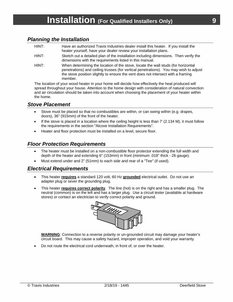
Electrical Requirements • This heater requires a standard 120 volt, 60 Hz grounded electrical outlet. Do not use an
adapter plug or sever the grounding plug.
• This heater requires correct polarity. The line (hot) is on the right and has a smaller plug. The neutral (common) is on the left and has a larger plug. Use a circuit tester (available at hardware stores) or contact an electrician to verify correct polarity and ground.
WARNING: Connection to a reverse polarity or un-grounded circuit may damage your heater’s circuit board. This may cause a safety hazard, improper operation, and void your warranty.
• Do not route the electrical cord underneath, in front of, or over the heater.
10 Installation (For Qualified Installers Only)
© Travis Industries 2/18/19 - 1445 Deerfield Stove
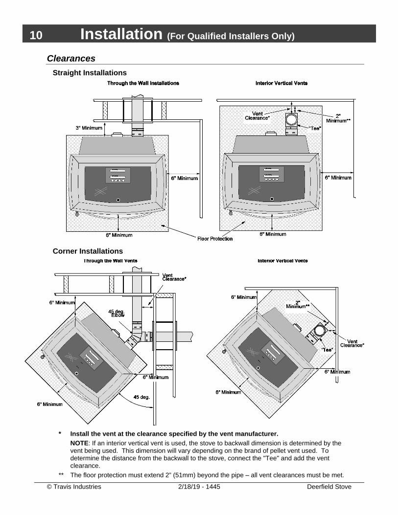
Clearances Straight Installations
Corner Installations
* Install the vent at the clearance specified by the vent manufacturer.
NOTE: If an interior vertical vent is used, the stove to backwall dimension is determined by the vent being used. This dimension will vary depending on the brand of pellet vent used. To determine the distance from the backwall to the stove, connect the "Tee" and add the vent clearance.
** The floor protection must extend 2” (51mm) beyond the pipe – all vent clearances must be met.
Installation (For Qualified Installers Only) 11
© Travis Industries 2/18/19 - 1445 Deerfield Stove
Venting the Pellet Stove • INSTALL VENT AT CLEARANCES SPECIFIED BY THE VENT MANUFACTURER. • DO NOT CONNECT THE PELLET VENT TO A VENT SERVING ANY OTHER APPLIANCE OR
STOVE. • DO NOT INSTALL A FLUE DAMPER IN THE EXHAUST VENTING SYSTEM OF THIS UNIT. • USE AN APPROVED WALL THIMBLE WHEN PASSING THE VENT THROUGH WALLS AND
A CEILING SUPPORT/FIRE STOP SPACER WHEN PASSING THE VENT THROUGH CEILINGS (MAKE SURE TO MAINTAIN CLEARANCE TO ANY COMBUSTIBLES).
• No more than one tee and 180° of elbows (one tee with two 90° elbows, one tee with one 90° and two 45° elbows, etc.).
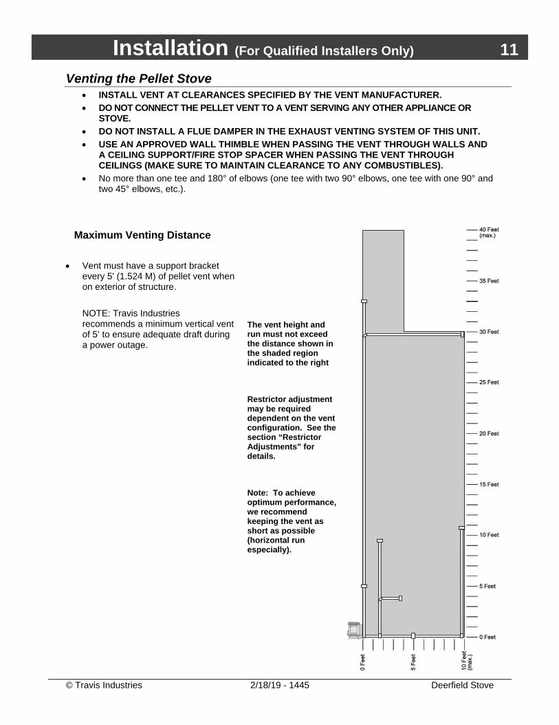
Maximum Venting Distance
• Vent must have a support bracket every 5' (1.524 M) of pellet vent when on exterior of structure. NOTE: Travis Industries recommends a minimum vertical vent of 5’ to ensure adequate draft during a power outage.
The vent height and run must not exceed the distance shown in the shaded region indicated to the right Restrictor adjustment may be required dependent on the vent configuration. See the section “Restrictor Adjustments” for details. Note: To achieve optimum performance, we recommend keeping the vent as short as possible (horizontal run especially).
12 Installation (For Qualified Installers Only)
© Travis Industries 2/18/19 - 1445 Deerfield Stove
Pellet Vent Type • Must be 3" (76mm) or 4” (102mm) diameter Type "L" (except for masonry fireplace installations) -
or - connect the vent to a factory built type "A" chimney.
Installing the Pellet Vent
• Secure each vent section (including the connection to the heater, adapters, elbows, etc…)
following the directions provided by the vent manufacturer or by using 3 sheet metal screws (1/4” Max.).
• Horizontal sections must have a 1/4" (6.4mm) rise every 12" (305mm) of travel. • Install the vent at the clearances specified by the vent manufacturer.
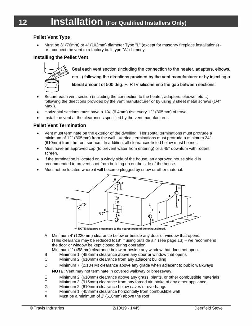
Pellet Vent Termination • Vent must terminate on the exterior of the dwelling. Horizontal terminations must protrude a
minimum of 12" (305mm) from the wall. Vertical terminations must protrude a minimum 24" (610mm) from the roof surface. In addition, all clearances listed below must be met.
• Must have an approved cap (to prevent water from entering) or a 45° downturn with rodent screen.
• If the termination is located on a windy side of the house, an approved house shield is recommended to prevent soot from building up on the side of the house.
• Must not be located where it will become plugged by snow or other material.
A Minimum 4' (1220mm) clearance below or beside any door or window that opens.
(This clearance may be reduced to18” if using outside air (see page 13) – we recommend the door or window be kept closed during operation. Minimum 1’ (458mm) clearance below or beside any window that does not open.
B Minimum 1' (458mm) clearance above any door or window that opens C Minimum 2' (610mm) clearance from any adjacent building D Minimum 7' (2.134 M) clearance above any grade when adjacent to public walkways
NOTE: Vent may not terminate in covered walkway or breezeway. E Minimum 2' (610mm) clearance above any grass, plants, or other combustible materials F Minimum 3' (915mm) clearance from any forced air intake of any other appliance G Minimum 2' (610mm) clearance below eaves or overhangs H Minimum 1' (458mm) clearance horizontally from combustible wall X Must be a minimum of 2' (610mm) above the roof
Installation (For Qualified Installers Only) 13
© Travis Industries 5/5/20 - 1445 Deerfield Stove
Mobile Home Requirements Outside air is required (used for combustion) - see the directions below.
The heater must be bolted to the floor (Some states do not require this; check with your local building department).
The heater must be grounded to the steel chassis of the mobile home (Some states do not require this; check with your local building department).
DO NOT INSTALL IN SLEEPING ROOM.
CAUTION: THE STRUCTURAL INTEGRITY OF THE MANUFACTURED HOME FLOOR, WALL, AND CEILING/ROOF MUST BE MAINTAINED.
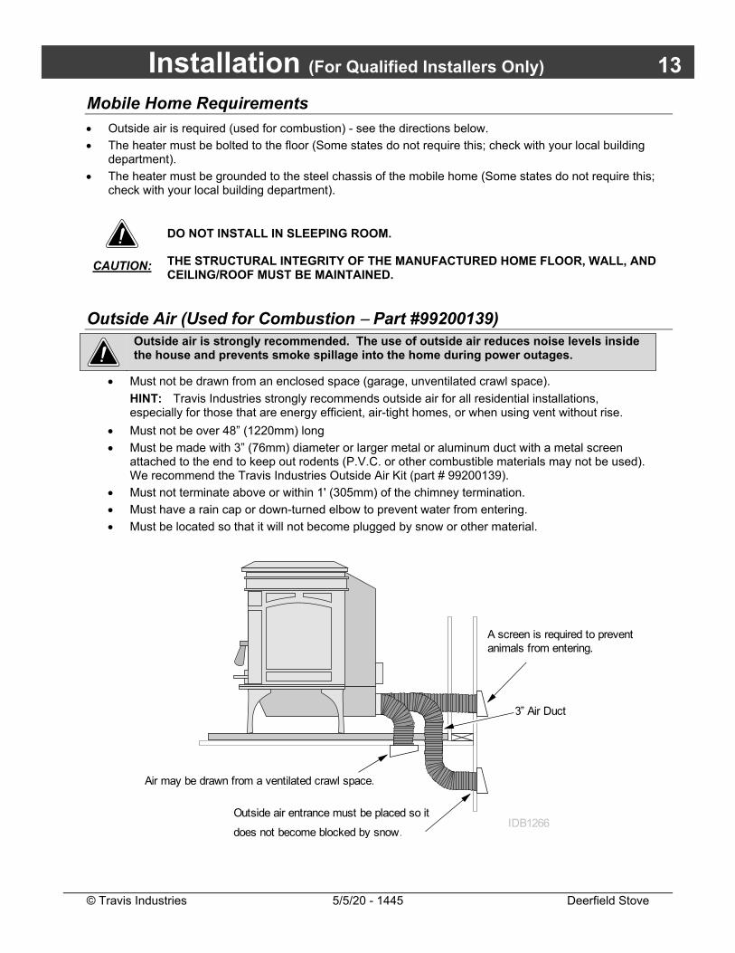
Outside Air (Used for Combustion Part #99200139)
Outside air is strongly recommended. The use of outside air reduces noise levels inside the house and prevents smoke spillage into the home during power outages.
Must not be drawn from an enclosed space (garage, unventilated crawl space).
HINT: Travis Industries strongly recommends outside air for all residential installations, especially for those that are energy efficient, air-tight homes, or when using vent without rise.
Must not be over 48” (1220mm) long
Must be made with 3” (76mm) diameter or larger metal or aluminum duct with a metal screen attached to the end to keep out rodents (P.V.C. or other combustible materials may not be used). We recommend the Travis Industries Outside Air Kit (part # 99200139).
Must not terminate above or within 1' (305mm) of the chimney termination.
Must have a rain cap or down-turned elbow to prevent water from entering.
Must be located so that it will not become plugged by snow or other material.
3” Air Duct
A screen is required to prevent animals from entering.
Outside air entrance must be placed so it
does not become blocked by snow.
Air may be drawn from a ventilated crawl space.
IDB1266
14 Installation (For Qualified Installers Only)
© Travis Industries 2/18/19 - 1445 Deerfield Stove
Alcove Installation Requirements When the pellet stove is placed in a location where the ceiling height is less than 7' (2.134 M) tall, it is considered an alcove installation. Because of the reduced height, the requirements listed below must be met.
Minimum Width 40-1/4“ Maximum Depth 48” Minimum Height 60“
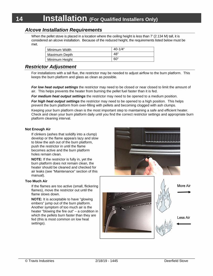
Restrictor Adjustment For installations with a tall flue, the restrictor may be needed to adjust airflow to the burn platform. This keeps the burn platform and glass as clean as possible. For low heat output settings the restrictor may need to be closed or near closed to limit the amount of air. This helps prevents the heater from burning the pellet fuel faster than it is fed. For medium heat output settings the restrictor may need to be opened to a medium position. For high heat output settings the restrictor may need to be opened to a high position. This helps prevent the burn platform from over-filling with pellets and becoming clogged with ash clumps. Keeping your burn platform clean is the most important step to maintaining a safe and efficient heater. Check and clean your burn platform daily until you find the correct restrictor settings and appropriate burn platform cleaning interval.
Not Enough Air If clinkers (ashes that solidify into a clump) develop or the flame appears lazy and slow to blow the ash out of the burn platform, push the restrictor in until the flame becomes active and the burn platform holes remain clean. NOTE: If the restrictor is fully in, yet the burn platform does not remain clean, the heater should be cleaned and checked for air leaks (see “Maintenance” section of this manual).
Too Much Air If the flames are too active (small, flickering flames), move the restrictor out until the flame slows down. NOTE: It is acceptable to have “glowing embers” jump out of the burn platform. Another symptom of too much air is the heater “blowing the fire out” – a condition in which the pellets burn faster than they are fed (this is most common on low heat settings).
Installation (For Qualified Installers Only) 15
© Travis Industries 2/18/19 - 1445 Deerfield Stove
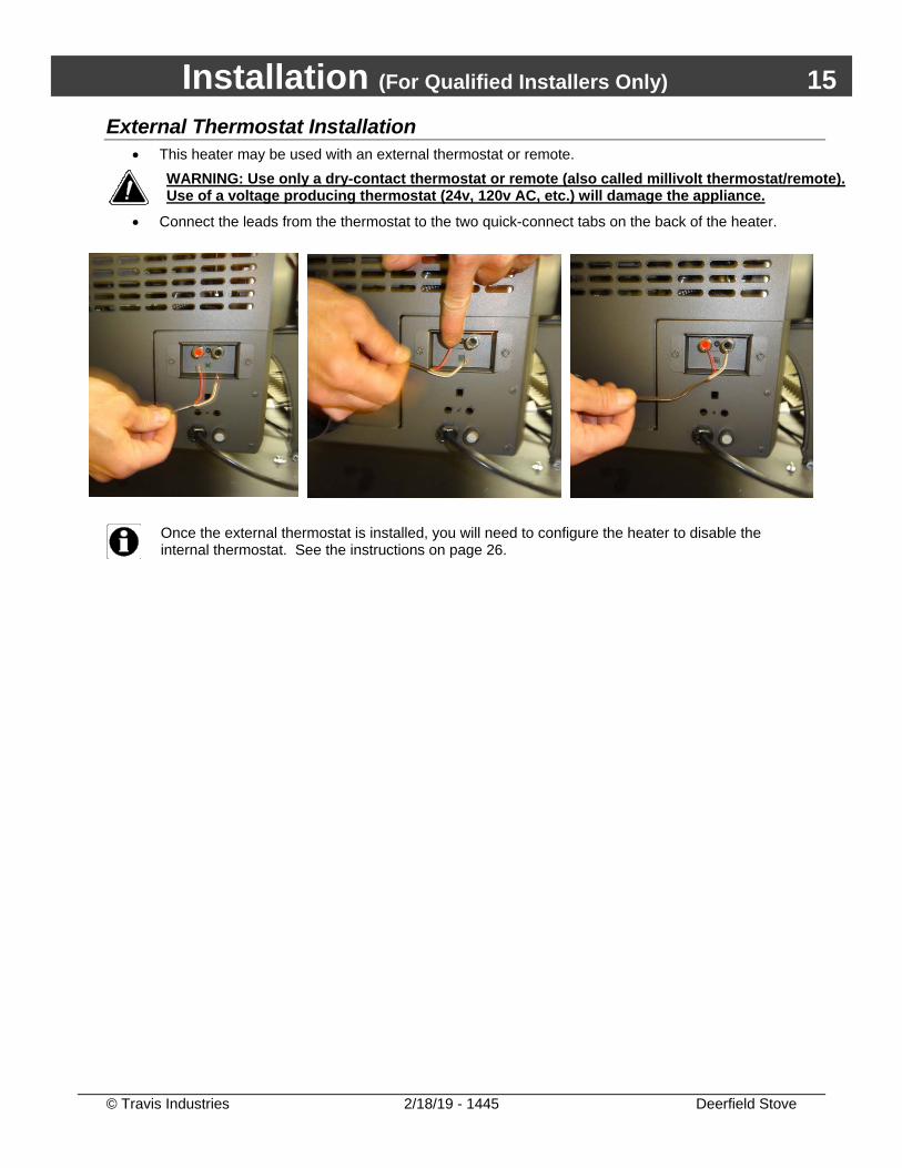
External Thermostat Installation • This heater may be used with an external thermostat or remote.
WARNING: Use only a dry-contact thermostat or remote (also called millivolt thermostat/remote). Use of a voltage producing thermostat (24v, 120v AC, etc.) will damage the appliance.
• Connect the leads from the thermostat to the two quick-connect tabs on the back of the heater.
Once the external thermostat is installed, you will need to configure the heater to disable the internal thermostat. See the instructions on page 26.
16 Installation (For Qualified Installers Only)
© Travis Industries 2/18/19 - 1445 Deerfield Stove
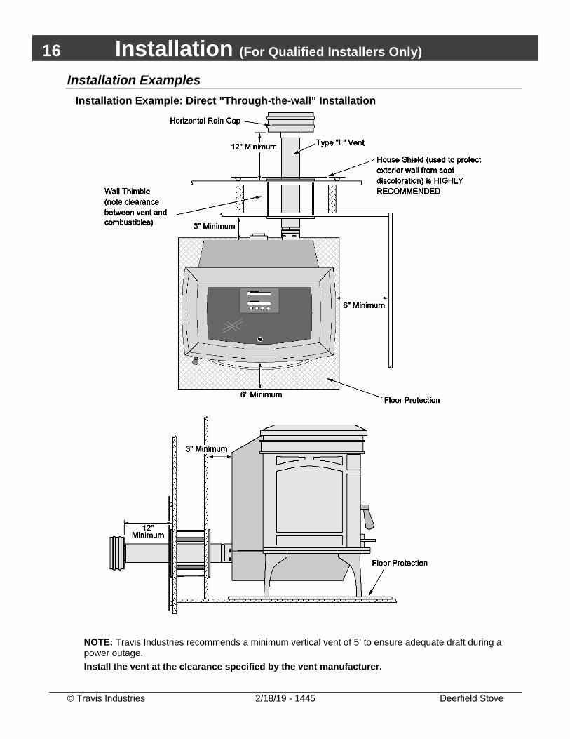
Installation Examples Installation Example: Direct "Through-the-wall" Installation
NOTE: Travis Industries recommends a minimum vertical vent of 5’ to ensure adequate draft during a power outage. Install the vent at the clearance specified by the vent manufacturer.
Installation (For Qualified Installers Only) 17
© Travis Industries 2/18/19 - 1445 Deerfield Stove
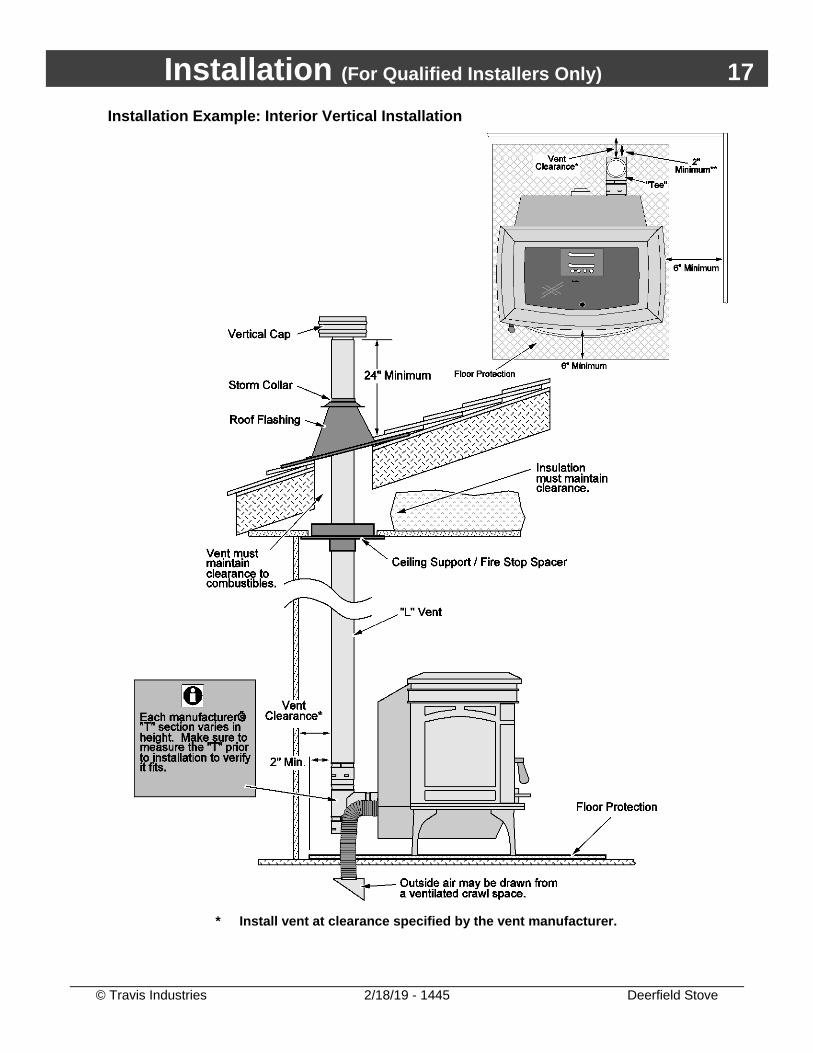
Installation Example: Interior Vertical Installation
* Install vent at clearance specified by the vent manufacturer.
18 Installation (For Qualified Installers Only)
© Travis Industries 2/18/19 - 1445 Deerfield Stove
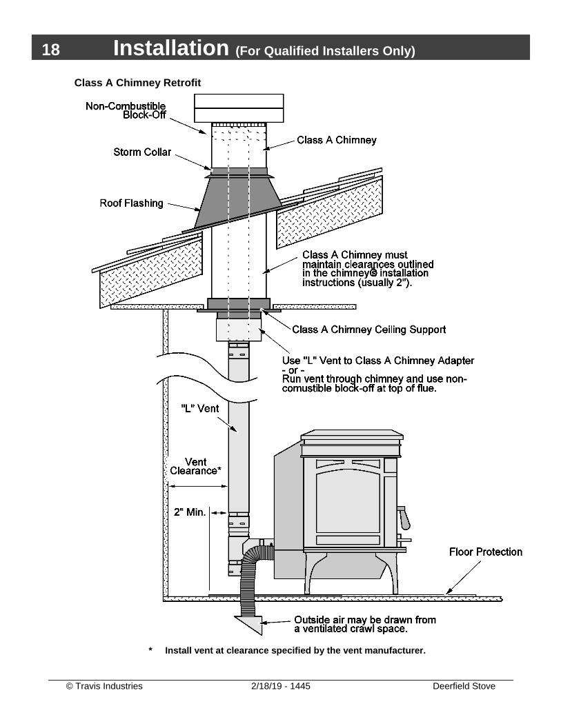
Class A Chimney Retrofit
* Install vent at clearance specified by the vent manufacturer.
Installation (For Qualified Installers Only) 19
© Travis Industries 2/18/19 - 1445 Deerfield Stove
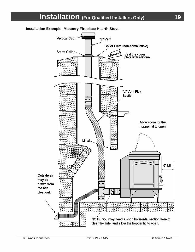
Installation Example: Masonry Fireplace Hearth Stove
20 Installation (For Qualified Installers Only)
© Travis Industries 2/18/19 - 1445 Deerfield Stove
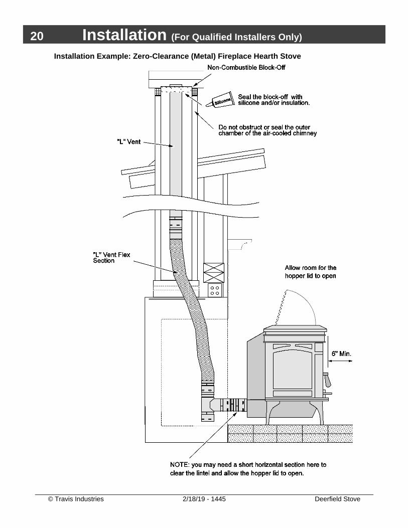
Installation Example: Zero-Clearance (Metal) Fireplace Hearth Stove
Installation (For Qualified Installers Only) 21
© Travis Industries 2/18/19 - 1445 Deerfield Stove
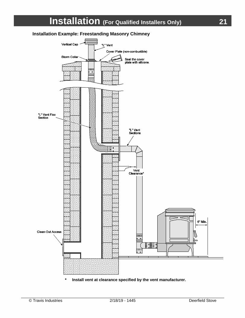
Installation Example: Freestanding Masonry Chimney
* Install vent at clearance specified by the vent manufacturer.
22 Operation
© Travis Industries 2/18/19 - 1445 Deerfield Stove
Safety Notice READ THIS ENTIRE MANUAL (ESPECIALLY THE "SAFETY PRECAUTIONS" ON PAGES 4 AND 5) BEFORE USING THIS HEATER. FAILURE TO FOLLOW THE INSTRUCTIONS MAY RESULT IN PROPERTY DAMAGE, BODILY INJURY, OR EVEN DEATH.
DO NOT UNPLUG THE HEATER TO TURN IT OFF. THIS HEATER RELIES UPON ELECTRICITY TO PUSH THE FLUE GASES OUT THE PELLET VENT – UNPLUGGING IT MAY LEAD TO SMOKE ENTERING YOUR ROOM.
FAILURE TO MAINTAIN YOUR HEATER WILL LEAD TO A RESTRICTED COMBUSTION AIR SYSTEM, LEADING TO POOR PERFORMANCE AND IN SOME CASES, SMOKE SPILLAGE INTO THE ROOM. SEE THE "MAINTENANCE" SECTION FOR DETAILS.
DO NOT USE CHEMICALS OR FLAMMABLE FLUIDS TO START THIS HEATER.
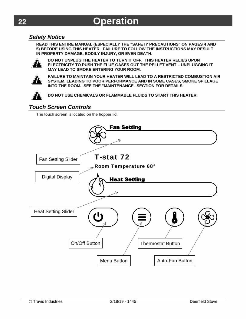
Touch Screen Controls The touch screen is located on the hopper lid.
Heat Setting Slider
On/Off Button
Menu Button
Thermostat Button
Auto-Fan Button
T-stat 72 Room Temperature 68°
Fan Setting Slider
Digital Display
Operation 23
© Travis Industries 2/18/19 - 1445 Deerfield Stove
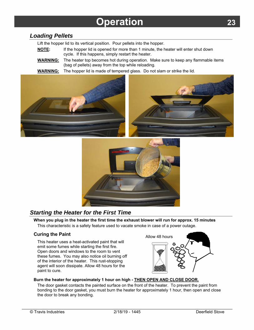
Loading Pellets Lift the hopper lid to its vertical position. Pour pellets into the hopper. NOTE: If the hopper lid is opened for more than 1 minute, the heater will enter shut down
cycle. If this happens, simply restart the heater. WARNING: The heater top becomes hot during operation. Make sure to keep any flammable items
(bag of pellets) away from the top while reloading. WARNING: The hopper lid is made of tempered glass. Do not slam or strike the lid.
Starting the Heater for the First Time When you plug in the heater the first time the exhaust blower will run for approx. 15 minutes
This characteristic is a safety feature used to vacate smoke in case of a power outage.
Curing the Paint
This heater uses a heat-activated paint that will emit some fumes while starting the first fire. Open doors and windows to the room to vent these fumes. You may also notice oil burning off of the interior of the heater. This rust-stopping agent will soon dissipate. Allow 48 hours for the paint to cure.
Burn the heater for approximately 1 hour on high - THEN OPEN AND CLOSE DOOR. The door gasket contacts the painted surface on the front of the heater. To prevent the paint from bonding to the door gasket, you must burn the heater for approximately 1 hour, then open and close the door to break any bonding.
�������
����
2 to 4 hoursAllow 48 hours
24 Operation
© Travis Industries 2/18/19 - 1445 Deerfield Stove
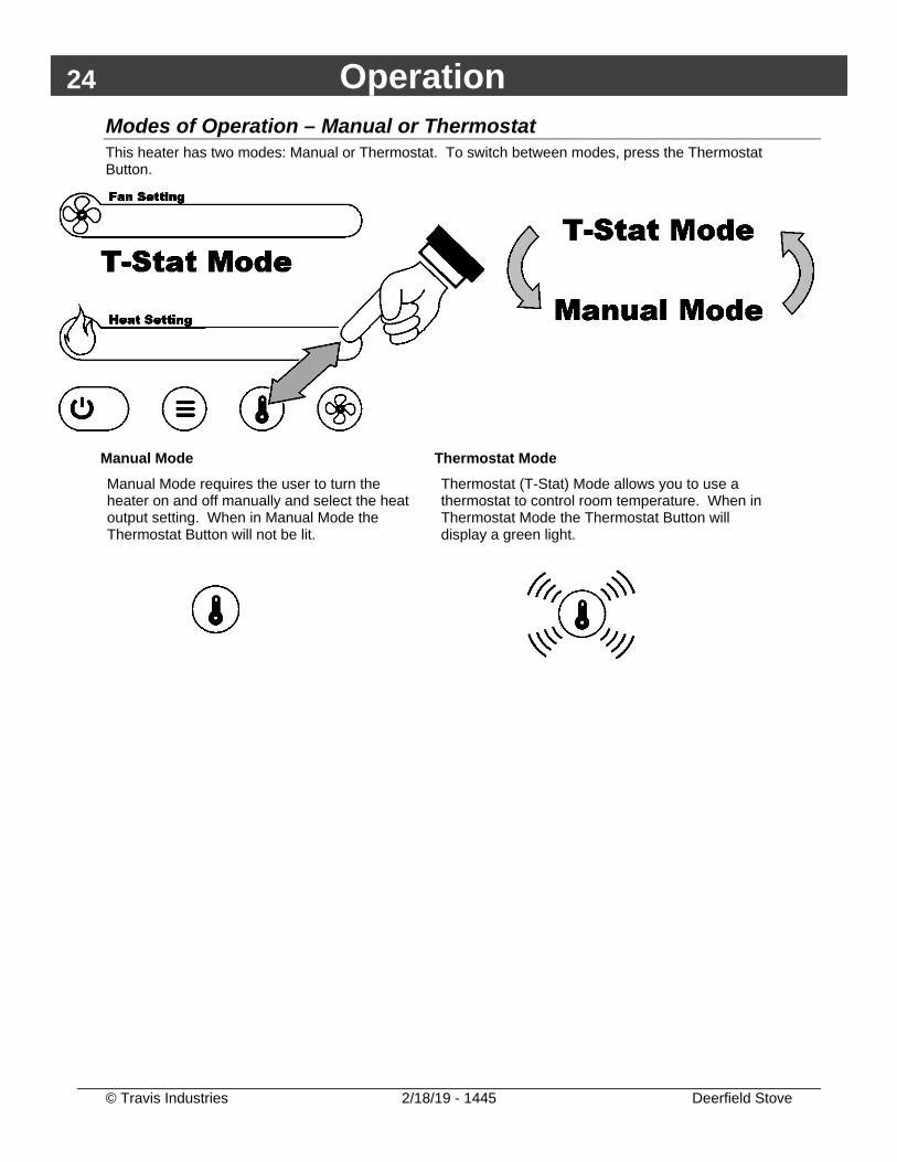
Modes of Operation – Manual or Thermostat This heater has two modes: Manual or Thermostat. To switch between modes, press the Thermostat Button.
Manual Mode Manual Mode requires the user to turn the heater on and off manually and select the heat output setting. When in Manual Mode the Thermostat Button will not be lit.
Thermostat Mode Thermostat (T-Stat) Mode allows you to use a thermostat to control room temperature. When in Thermostat Mode the Thermostat Button will display a green light.
Operation 25
© Travis Industries 2/18/19 - 1445 Deerfield Stove
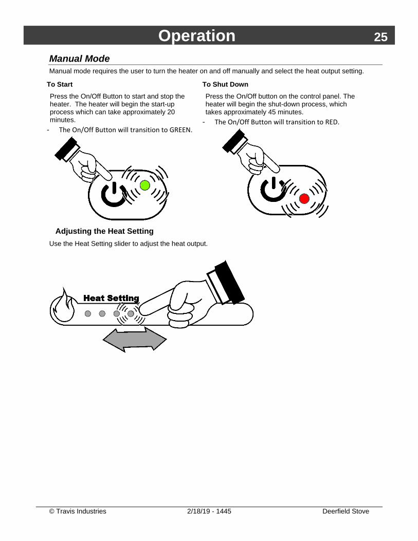
Manual Mode Manual mode requires the user to turn the heater on and off manually and select the heat output setting.
To Start Press the On/Off Button to start and stop the heater. The heater will begin the start-up process which can take approximately 20 minutes.
- The On/Off Button will transition to GREEN.
To Shut Down Press the On/Off button on the control panel. The heater will begin the shut-down process, which takes approximately 45 minutes.
- The On/Off Button will transition to RED.
Adjusting the Heat Setting Use the Heat Setting slider to adjust the heat output.
26 Operation
© Travis Industries 2/18/19 - 1445 Deerfield Stove
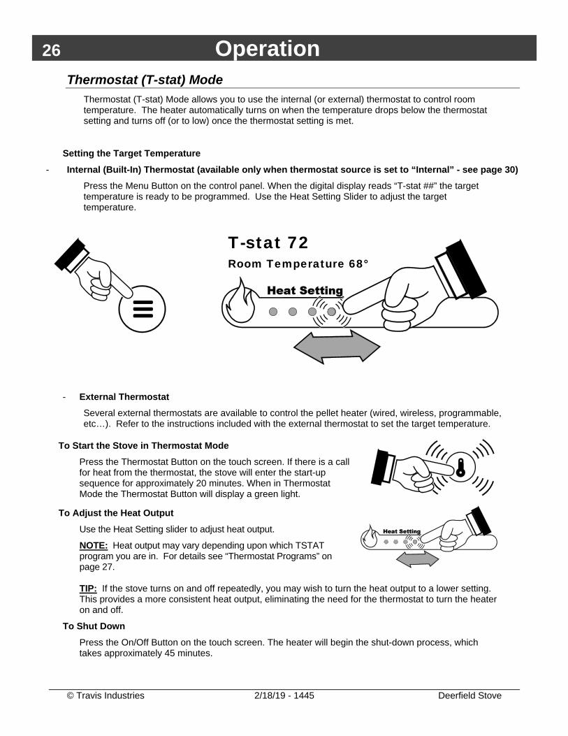
Thermostat (T-stat) Mode Thermostat (T-stat) Mode allows you to use the internal (or external) thermostat to control room temperature. The heater automatically turns on when the temperature drops below the thermostat setting and turns off (or to low) once the thermostat setting is met.
Setting the Target Temperature - Internal (Built-In) Thermostat (available only when thermostat source is set to “Internal” - see page 30)
Press the Menu Button on the control panel. When the digital display reads “T-stat ##” the target temperature is ready to be programmed. Use the Heat Setting Slider to adjust the target temperature.
- External Thermostat
Several external thermostats are available to control the pellet heater (wired, wireless, programmable, etc…). Refer to the instructions included with the external thermostat to set the target temperature.
To Start the Stove in Thermostat Mode Press the Thermostat Button on the touch screen. If there is a call for heat from the thermostat, the stove will enter the start-up sequence for approximately 20 minutes. When in Thermostat Mode the Thermostat Button will display a green light.
To Adjust the Heat Output Use the Heat Setting slider to adjust heat output.
NOTE: Heat output may vary depending upon which TSTAT program you are in. For details see “Thermostat Programs” on page 27.
TIP: If the stove turns on and off repeatedly, you may wish to turn the heat output to a lower setting. This provides a more consistent heat output, eliminating the need for the thermostat to turn the heater on and off.
To Shut Down Press the On/Off Button on the touch screen. The heater will begin the shut-down process, which takes approximately 45 minutes.
T-stat 72 Room Temperature 68°
Operation 27
© Travis Industries 2/18/19 - 1445 Deerfield Stove
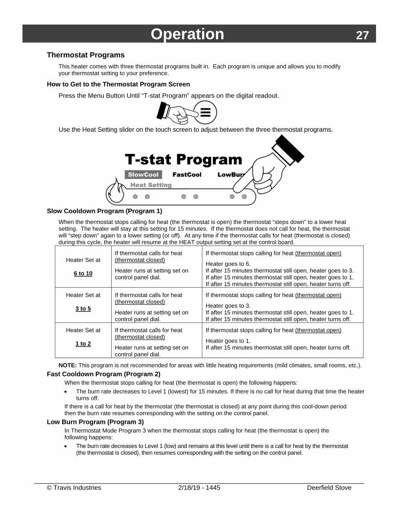
Thermostat Programs This heater comes with three thermostat programs built in. Each program is unique and allows you to modify your thermostat setting to your preference.
How to Get to the Thermostat Program Screen Press the Menu Button Until “T-stat Program” appears on the digital readout.
Use the Heat Setting slider on the touch screen to adjust between the three thermostat programs.
Slow Cooldown Program (Program 1)
When the thermostat stops calling for heat (the thermostat is open) the thermostat “steps down” to a lower heat setting. The heater will stay at this setting for 15 minutes. If the thermostat does not call for heat, the thermostat will “step down” again to a lower setting (or off). At any time if the thermostat calls for heat (thermostat is closed) during this cycle, the heater will resume at the HEAT output setting set at the control board.
Heater Set at
6 to 10
If thermostat calls for heat (thermostat closed)
Heater runs at setting set on control panel dial.
If thermostat stops calling for heat (thermostat open)
Heater goes to 6. If after 15 minutes thermostat still open, heater goes to 3. If after 15 minutes thermostat still open, heater goes to 1. If after 15 minutes thermostat still open, heater turns off.
Heater Set at
3 to 5
If thermostat calls for heat (thermostat closed)
Heater runs at setting set on control panel dial.
If thermostat stops calling for heat (thermostat open)
Heater goes to 3. If after 15 minutes thermostat still open, heater goes to 1. If after 15 minutes thermostat still open, heater turns off.
Heater Set at
1 to 2
If thermostat calls for heat (thermostat closed)
Heater runs at setting set on control panel dial.
If thermostat stops calling for heat (thermostat open)
Heater goes to 1. If after 15 minutes thermostat still open, heater turns off.
NOTE: This program is not recommended for areas with little heating requirements (mild climates, small rooms, etc.). Fast Cooldown Program (Program 2)
When the thermostat stops calling for heat (the thermostat is open) the following happens: • The burn rate decreases to Level 1 (lowest) for 15 minutes. If there is no call for heat during that time the heater
turns off. If there is a call for heat by the thermostat (the thermostat is closed) at any point during this cool-down period then the burn rate resumes corresponding with the setting on the control panel.
Low Burn Program (Program 3) In Thermostat Mode Program 3 when the thermostat stops calling for heat (the thermostat is open) the following happens: • The burn rate decreases to Level 1 (low) and remains at this level until there is a call for heat by the thermostat
(the thermostat is closed), then resumes corresponding with the setting on the control panel.
28 Operation
© Travis Industries 2/18/19 - 1445 Deerfield Stove
Fan Setting There are two options for adjusting the room-air circulating fan.
The fan will turn on only after the heater is up to temperature (approximately 15 minutes after starting).
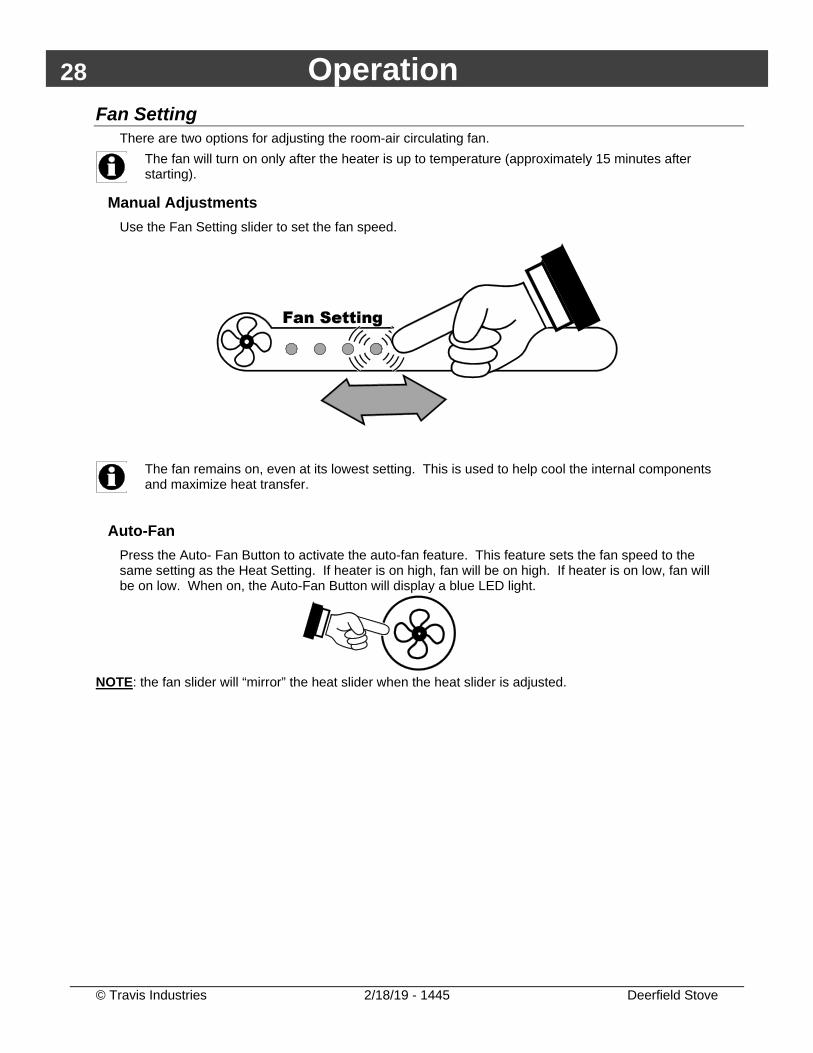
Manual Adjustments Use the Fan Setting slider to set the fan speed.
The fan remains on, even at its lowest setting. This is used to help cool the internal components and maximize heat transfer.
Auto-Fan Press the Auto- Fan Button to activate the auto-fan feature. This feature sets the fan speed to the same setting as the Heat Setting. If heater is on high, fan will be on high. If heater is on low, fan will be on low. When on, the Auto-Fan Button will display a blue LED light.
NOTE: the fan slider will “mirror” the heat slider when the heat slider is adjusted.
Operation 29
© Travis Industries 2/18/19 - 1445 Deerfield Stove
Heater Status This heater has unique phases of operation (also called Heater Status). The descriptions below details these phases to help the homeowner better understand how the pellet heater works.
Standby The heater is plugged in, cool, and is not in operation.
Start-Up Once the heater is started, it will go through Start-Up phase. This phase turns the igniter on and feeds pellets to the burn platform. Once Start-Up is complete the heater will enter the Heating phase.
Heating The heater is on, pellets are being fed to the burn platform and are burning, the system detects heat and the room fan is circulating air. When the heater is turned off (either manually, through a thermostat, or a fault occurred), the heater moves to the Cool-Down phase.
Cool-Down The phase indicates heater has recently been turned off. The heater will be warm, the pellets in the auger will be fed to the burn platform but new pellets are not being fed to the auger. This phase is necessary to ensure all remaining pellets are burned and flue products are expelled. Once the cool-down phase is complete, the heater will go to Standby phase.
Fault If the heater encounters a situation that is not normal, it goes into Fault status. The heater will go into cool-down and the fault encountered will be displayed. The most common fault encountered are:
- Running out of pellets - Power Outage
The fault status is used to help the homeowner monitor heater operation.
30 Operation
© Travis Industries 2/18/19 - 1445 Deerfield Stove
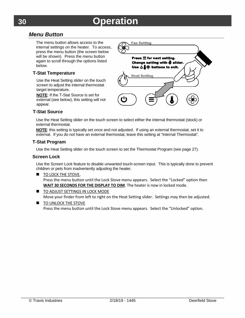
Menu Button The menu button allows access to the internal settings on the heater. To access, press the menu button (the screen below will be shown). Press the menu button again to scroll through the options listed below.
T-Stat Temperature Use the Heat Setting slider on the touch screen to adjust the internal thermostat target temperature. NOTE: If the T-Stat Source is set for external (see below), this setting will not appear.
T-Stat Source
Use the Heat Setting slider on the touch screen to select either the internal thermostat (stock) or external thermostat. NOTE: this setting is typically set once and not adjusted. If using an external thermostat, set it to external. If you do not have an external thermostat, leave this setting at “Internal Thermostat”.
T-Stat Program Use the Heat Setting slider on the touch screen to set the Thermostat Program (see page 27).
Screen Lock Use the Screen Lock feature to disable unwanted touch-screen input. This is typically done to prevent children or pets from inadvertently adjusting the heater. TO LOCK THE STOVE,
Press the menu button until the Lock Stove menu appears. Select the “Locked” option then WAIT 30 SECONDS FOR THE DISPLAY TO DIM. The heater is now in locked mode.
TO ADJUST SETTINGS IN LOCK MODE Move your finder from left to right on the Heat Setting slider. Settings may then be adjusted.
TO UNLOCK THE STOVE Press the menu button until the Lock Stove menu appears. Select the “Unlocked” option.
Operation 31
© Travis Industries 2/18/19 - 1445 Deerfield Stove
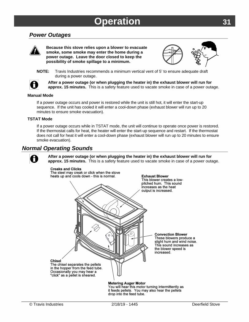
Power Outages
Because this stove relies upon a blower to evacuate smoke, some smoke may enter the home during a power outage. Leave the door closed to keep the possibility of smoke spillage to a minimum.
NOTE: Travis Industries recommends a minimum vertical vent of 5’ to ensure adequate draft
during a power outage.
After a power outage (or when plugging the heater in) the exhaust blower will run for approx. 15 minutes. This is a safety feature used to vacate smoke in case of a power outage.
Manual Mode If a power outage occurs and power is restored while the unit is still hot, it will enter the start-up sequence. If the unit has cooled it will enter a cool-down phase (exhaust blower will run up to 20 minutes to ensure smoke evacuation).
TSTAT Mode If a power outage occurs while in TSTAT mode, the unit will continue to operate once power is restored. If the thermostat calls for heat, the heater will enter the start-up sequence and restart. If the thermostat does not call for heat it will enter a cool-down phase (exhaust blower will run up to 20 minutes to ensure smoke evacuation).
Normal Operating Sounds
After a power outage (or when plugging the heater in) the exhaust blower will run for approx. 15 minutes. This is a safety feature used to vacate smoke in case of a power outage.
32 Maintenance
© Travis Industries 2/18/19 - 1445 Deerfield Stove
Stove Maintenance
The following section details extensive maintenance procedures. We strongly suggest these items be carried out by a trained service technician, possibly by a service agreement set up with your dealer. NOTE: Pellet quality may vary by supplier. Your maintenance schedule may need to be revised to accommodate the pellets used.
DISCONNECT THE POWER CORD AND MAKE SURE THE HEATER HAS FULLY COOLED (APPROXIMATELY 45 MINUTES) PRIOR TO CONDUCTING SERVICE.
Maintenance Schedule Weekly Maintenance (or every 5 bags of fuel):
• Inspect Burn • Clean the burn platform • Clean the heat exchanger
Monthly Maintenance (or every 20 bags of fuel): • Empty the ashpan • Clean the glass • Inspect the door • Clean firebox liners
Yearly Maintenance (or every ton of fuel): • Check for air leaks • Clean lower exhaust duct • Clean convection blower • Clean negative pressure tube • Clean the vent • Clean under burn platform • Adjust door hinge and latch • Check for air leaks
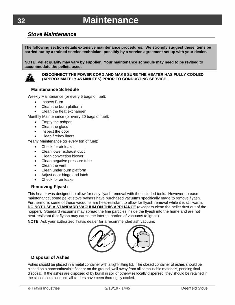
Removing Flyash This heater was designed to allow for easy flyash removal with the included tools. However, to ease maintenance, some pellet stove owners have purchased vacuums specifically made to remove flyash. Furthermore, some of these vacuums are heat-resistant to allow for flyash removal while it is still warm. DO NOT USE A STANDARD VACUUM ON THIS APPLIANCE (except to clean the pellet dust out of the hopper). Standard vacuums may spread the fine particles inside the flyash into the home and are not heat-resistant (hot flyash may cause the internal portion of vacuums to ignite). NOTE: Ask your authorized Travis dealer for a recommended ash vacuum.
Disposal of Ashes
Ashes should be placed in a metal container with a tight-fitting lid. The closed container of ashes should be placed on a noncombustible floor or on the ground, well away from all combustible materials, pending final disposal. If the ashes are disposed of by burial in soil or otherwise locally dispersed, they should be retained in the closed container until all cinders have been thoroughly cooled.
Maintenance 33
© Travis Industries 2/18/19 - 1445 Deerfield Stove
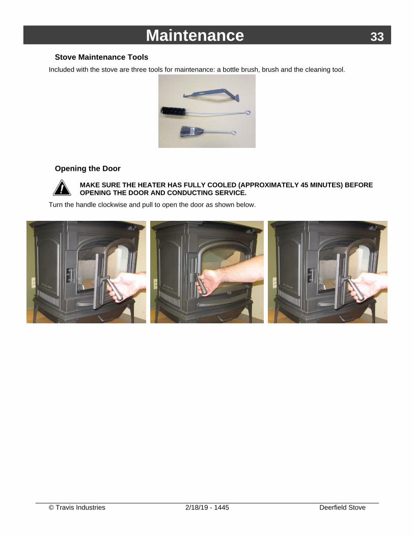
Stove Maintenance Tools Included with the stove are three tools for maintenance: a bottle brush, brush and the cleaning tool.
Opening the Door
MAKE SURE THE HEATER HAS FULLY COOLED (APPROXIMATELY 45 MINUTES) BEFORE OPENING THE DOOR AND CONDUCTING SERVICE.
Turn the handle clockwise and pull to open the door as shown below.
34 Maintenance
© Travis Industries 2/18/19 - 1445 Deerfield Stove
Weekly Maintenance (or Every 5 Bags of Pellets) - Inspect the Burn Once a week you should inspect the flame quality inside your appliance. When burning on high, the flames should be bright orange. If the flames seem to be coming only from the sides, or are orange/black, turn the heater off and check for clinkers (ashes that solidify into a clump). The most likely causes of clinkers are:
• Restrictor needs adjustment (see “Restrictor Adjustment” in the Installation section of this manual) NOTE: The optimum restrictor position will vary over time as soot builds up inside the exhaust system. See "Restrictor Adjustment" for details.
• Poor pellet quality
• The door or glass has an air leak
• The exhaust system requires cleaning
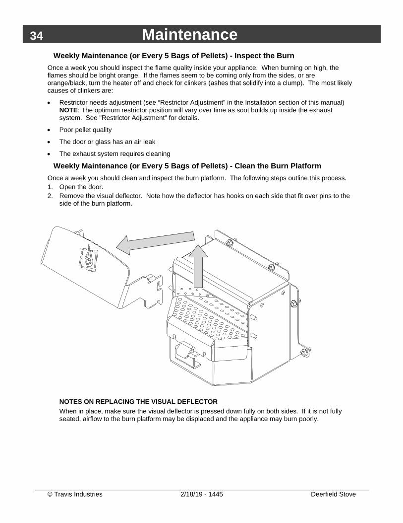
Weekly Maintenance (or Every 5 Bags of Pellets) - Clean the Burn Platform Once a week you should clean and inspect the burn platform. The following steps outline this process. 1. Open the door. 2. Remove the visual deflector. Note how the deflector has hooks on each side that fit over pins to the
side of the burn platform.
NOTES ON REPLACING THE VISUAL DEFLECTOR When in place, make sure the visual deflector is pressed down fully on both sides. If it is not fully seated, airflow to the burn platform may be displaced and the appliance may burn poorly.
Maintenance 35
© Travis Industries 2/18/19 - 1445 Deerfield Stove
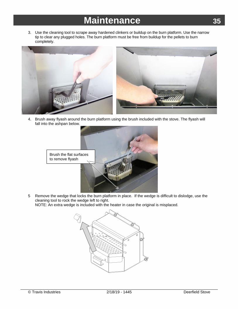
3. Use the cleaning tool to scrape away hardened clinkers or buildup on the burn platform. Use the narrow tip to clear any plugged holes. The burn platform must be free from buildup for the pellets to burn completely.
4. Brush away flyash around the burn platform using the brush included with the stove. The flyash will
fall into the ashpan below.
5 Remove the wedge that locks the burn platform in place. If the wedge is difficult to dislodge, use the
cleaning tool to rock the wedge left to right. NOTE: An extra wedge is included with the heater in case the original is misplaced.
Brush the flat surfaces to remove flyash
36 Maintenance
© Travis Industries 2/18/19 - 1445 Deerfield Stove
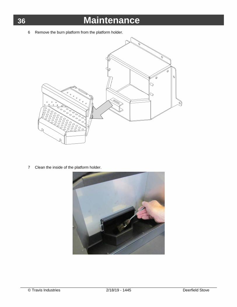
6 Remove the burn platform from the platform holder.
7 Clean the inside of the platform holder.
Maintenance 37
© Travis Industries 2/18/19 - 1445 Deerfield Stove
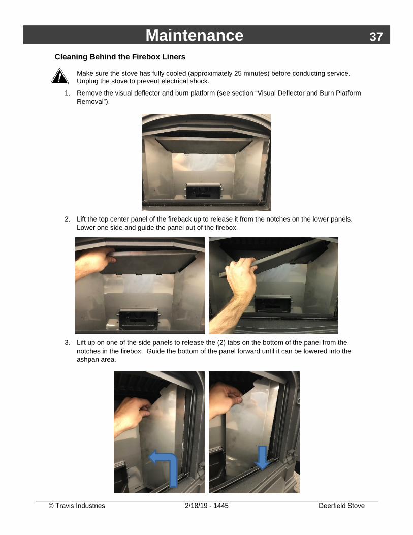
Cleaning Behind the Firebox Liners
Make sure the stove has fully cooled (approximately 25 minutes) before conducting service. Unplug the stove to prevent electrical shock.
1. Remove the visual deflector and burn platform (see section “Visual Deflector and Burn Platform Removal”).
2. Lift the top center panel of the fireback up to release it from the notches on the lower panels.
Lower one side and guide the panel out of the firebox.
3. Lift up on one of the side panels to release the (2) tabs on the bottom of the panel from the
notches in the firebox. Guide the bottom of the panel forward until it can be lowered into the ashpan area.
38 Maintenance
© Travis Industries 2/18/19 - 1445 Deerfield Stove
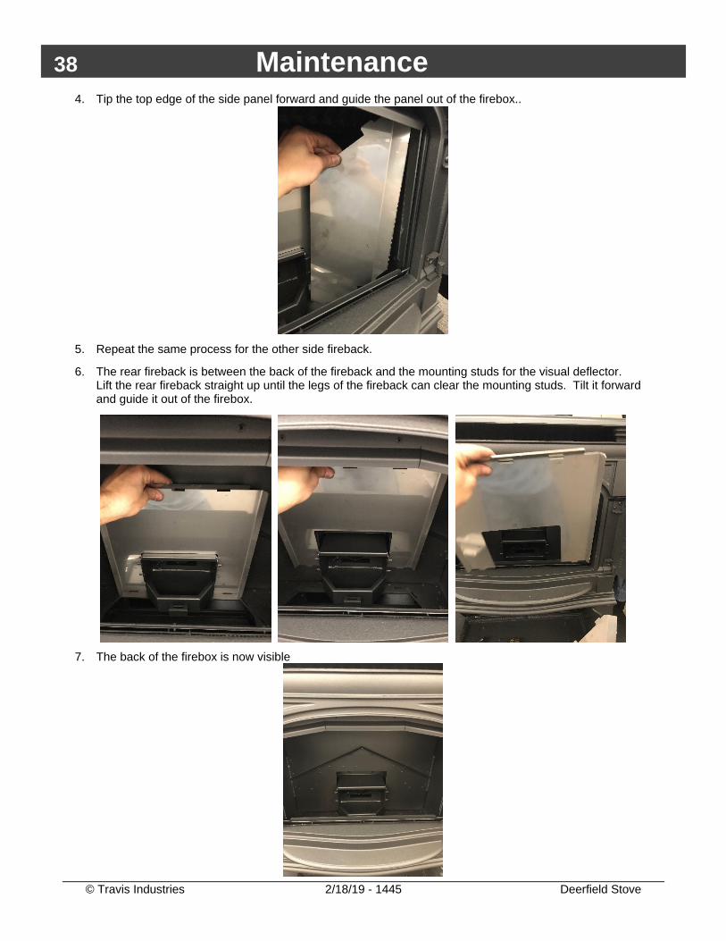
4. Tip the top edge of the side panel forward and guide the panel out of the firebox..
5. Repeat the same process for the other side fireback.
6. The rear fireback is between the back of the fireback and the mounting studs for the visual deflector. Lift the rear fireback straight up until the legs of the fireback can clear the mounting studs. Tilt it forward and guide it out of the firebox.
7. The back of the firebox is now visible
Maintenance 39
© Travis Industries 2/18/19 - 1445 Deerfield Stove
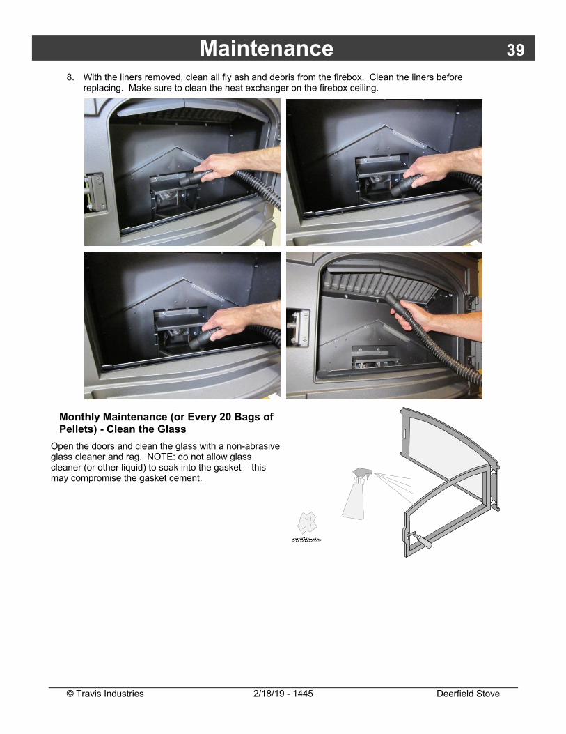
8. With the liners removed, clean all fly ash and debris from the firebox. Clean the liners before replacing. Make sure to clean the heat exchanger on the firebox ceiling.
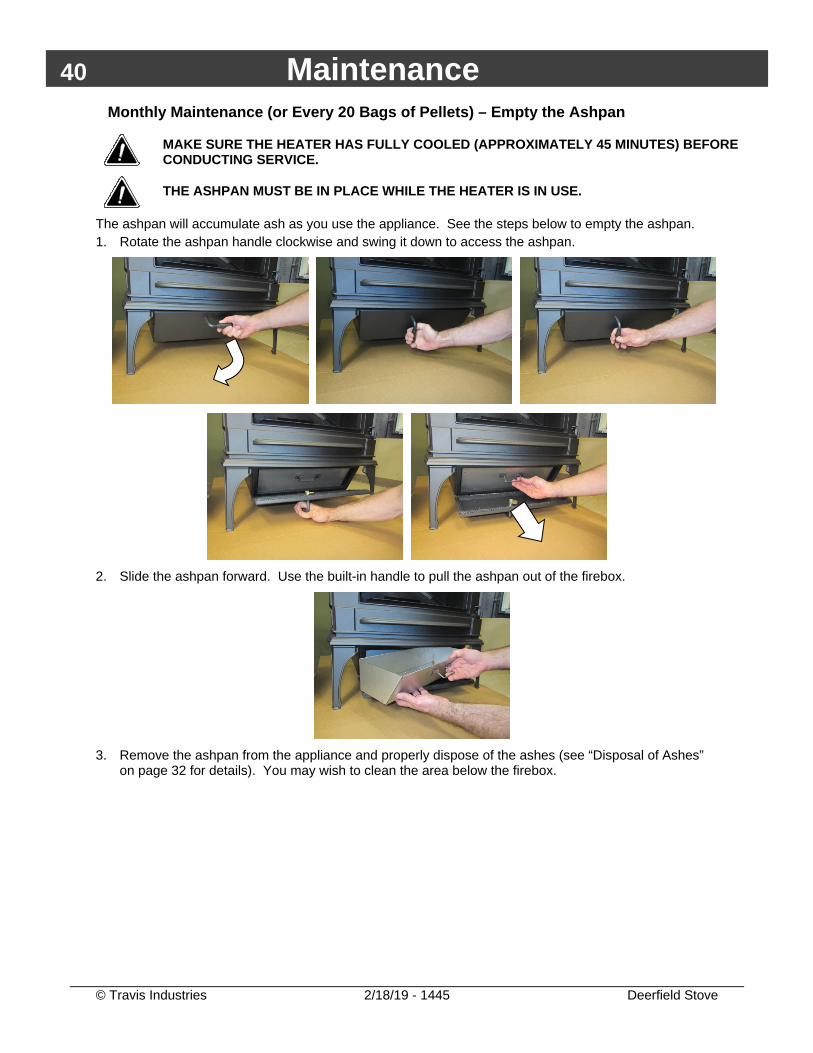
Monthly Maintenance (or Every 20 Bags of Pellets) - Clean the Glass
Open the doors and clean the glass with a non-abrasive glass cleaner and rag. NOTE: do not allow glass cleaner (or other liquid) to soak into the gasket – this may compromise the gasket cement.
���
����
40 Maintenance
© Travis Industries 2/18/19 - 1445 Deerfield Stove
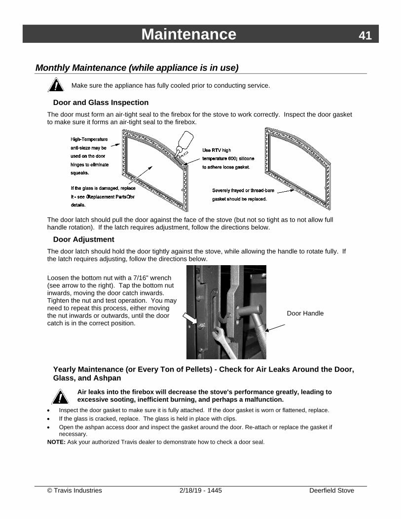
Monthly Maintenance (or Every 20 Bags of Pellets) – Empty the Ashpan
MAKE SURE THE HEATER HAS FULLY COOLED (APPROXIMATELY 45 MINUTES) BEFORE CONDUCTING SERVICE.
THE ASHPAN MUST BE IN PLACE WHILE THE HEATER IS IN USE.
The ashpan will accumulate ash as you use the appliance. See the steps below to empty the ashpan. 1. Rotate the ashpan handle clockwise and swing it down to access the ashpan.
2. Slide the ashpan forward. Use the built-in handle to pull the ashpan out of the firebox.
3. Remove the ashpan from the appliance and properly dispose of the ashes (see “Disposal of Ashes”
on page 32 for details). You may wish to clean the area below the firebox.
Maintenance 41
© Travis Industries 2/18/19 - 1445 Deerfield Stove
Monthly Maintenance (while appliance is in use)
Make sure the appliance has fully cooled prior to conducting service.
Door and Glass Inspection The door must form an air-tight seal to the firebox for the stove to work correctly. Inspect the door gasket to make sure it forms an air-tight seal to the firebox.
The door latch should pull the door against the face of the stove (but not so tight as to not allow full handle rotation). If the latch requires adjustment, follow the directions below.
Door Adjustment The door latch should hold the door tightly against the stove, while allowing the handle to rotate fully. If the latch requires adjusting, follow the directions below. Loosen the bottom nut with a 7/16” wrench (see arrow to the right). Tap the bottom nut inwards, moving the door catch inwards. Tighten the nut and test operation. You may need to repeat this process, either moving the nut inwards or outwards, until the door catch is in the correct position.
Door Handle
Yearly Maintenance (or Every Ton of Pellets) - Check for Air Leaks Around the Door, Glass, and Ashpan
Air leaks into the firebox will decrease the stove's performance greatly, leading to excessive sooting, inefficient burning, and perhaps a malfunction.
• Inspect the door gasket to make sure it is fully attached. If the door gasket is worn or flattened, replace. • If the glass is cracked, replace. The glass is held in place with clips. • Open the ashpan access door and inspect the gasket around the door. Re-attach or replace the gasket if
necessary. NOTE: Ask your authorized Travis dealer to demonstrate how to check a door seal.
42 Maintenance
© Travis Industries 2/18/19 - 1445 Deerfield Stove
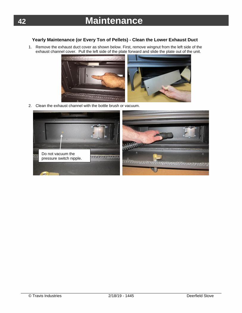
Yearly Maintenance (or Every Ton of Pellets) - Clean the Lower Exhaust Duct 1. Remove the exhaust duct cover as shown below. First, remove wingnut from the left side of the
exhaust channel cover. Pull the left side of the plate forward and slide the plate out of the unit.
2. Clean the exhaust channel with the bottle brush or vacuum.
Do not vacuum the pressure switch nipple.
Maintenance 43
© Travis Industries 2/18/19 - 1445 Deerfield Stove
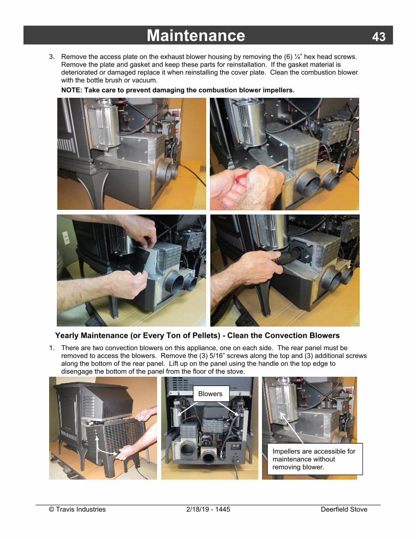
3. Remove the access plate on the exhaust blower housing by removing the (6) ¼” hex head screws. Remove the plate and gasket and keep these parts for reinstallation. If the gasket material is deteriorated or damaged replace it when reinstalling the cover plate. Clean the combustion blower with the bottle brush or vacuum. NOTE: Take care to prevent damaging the combustion blower impellers.
Yearly Maintenance (or Every Ton of Pellets) - Clean the Convection Blowers
1. There are two convection blowers on this appliance, one on each side. The rear panel must be removed to access the blowers. Remove the (3) 5/16” screws along the top and (3) additional screws along the bottom of the rear panel. Lift up on the panel using the handle on the top edge to disengage the bottom of the panel from the floor of the stove.
Impellers are accessible for maintenance without removing blower.
Blowers
44 Maintenance
© Travis Industries 2/18/19 - 1445 Deerfield Stove
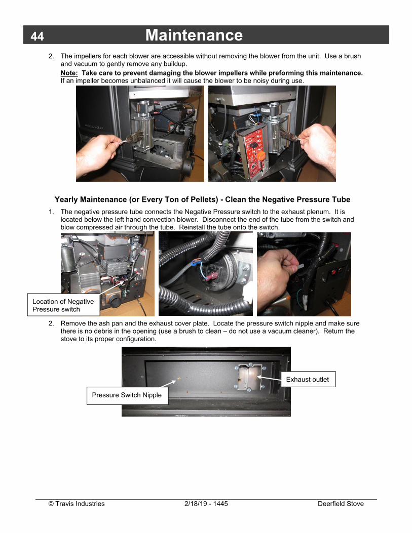
2. The impellers for each blower are accessible without removing the blower from the unit. Use a brush and vacuum to gently remove any buildup. Note: Take care to prevent damaging the blower impellers while preforming this maintenance. If an impeller becomes unbalanced it will cause the blower to be noisy during use.
Yearly Maintenance (or Every Ton of Pellets) - Clean the Negative Pressure Tube
1. The negative pressure tube connects the Negative Pressure switch to the exhaust plenum. It is located below the left hand convection blower. Disconnect the end of the tube from the switch and blow compressed air through the tube. Reinstall the tube onto the switch.
2. Remove the ash pan and the exhaust cover plate. Locate the pressure switch nipple and make sure there is no debris in the opening (use a brush to clean – do not use a vacuum cleaner). Return the stove to its proper configuration.
Location of Negative Pressure switch
Exhaust outlet
Pressure Switch Nipple
Maintenance 45
© Travis Industries 2/18/19 - 1445 Deerfield Stove
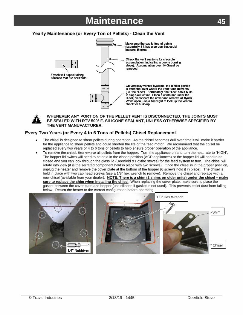
Yearly Maintenance (or Every Ton of Pellets) - Clean the Vent
WHENEVER ANY PORTION OF THE PELLET VENT IS DISCONNECTED, THE JOINTS MUST BE SEALED WITH RTV 500° F. SILICONE SEALANT, UNLESS OTHERWISE SPECIFIED BY THE VENT MANUFACTURER.
Every Two Years (or Every 4 to 6 Tons of Pellets) Chisel Replacement • The chisel is designed to shear pellets during operation. As the chisel becomes dull over time it will make it harder
for the appliance to shear pellets and could shorten the life of the feed motor. We recommend that the chisel be replaced every two years or 4 to 6 tons of pellets to help ensure proper operation of the appliance.
• To remove the chisel, first remove all pellets from the hopper. Turn the appliance on and turn the heat rate to “HIGH”. The hopper lid switch will need to be held in the closed position (AGP appliances) or the hopper lid will need to be closed and you can look through the glass lid (Deerfield & Foxfire stoves) for the feed system to turn. The chisel will rotate into view (it is the serrated component held in place with two screws). Once the chisel is in the proper position, unplug the heater and remove the cover plate at the bottom of the hopper (6 screws hold it in place). The chisel is held in place with two cap head screws (use a 1/8” hex wrench to remove). Remove the chisel and replace with a new chisel (available from your dealer). NOTE: There is a shim (2 shims on older units) under the chisel – make sure to replace the shim when installing the chisel. When replacing the cover plate, make sure to place the gasket between the cover plate and hopper (use silicone if gasket is not used). This prevents pellet dust from falling below. Return the heater to the correct configuration before operating.
1/8” Hex Wrench
Shim
Chisel
46 Maintenance
© Travis Industries 2/18/19 - 1445 Deerfield Stove
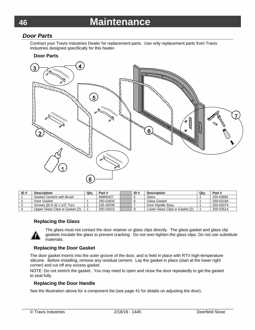
Door Parts Contract your Travis Industries Dealer for replacement parts. Use only replacement parts from Travis Industries designed specifically for this heater.
Door Parts
ID # Description Qty. Part # ID # Description Qty. Part # 1 Gasket Cement with Brush 99900427 5 Glass 1 250-03891 2 Door Gasket 1 250-02832 6 Glass Gasket 1 250-02184 3 Screws (8) 8-32 x 1/2” Torx 1 225-20039 7 Door Handle Assy. 1 250-02074 4 Upper Glass Clips w Gasket (2) 1 250-03515 8 Lower Glass Clips w Gasket (2) 1 250-03514
Replacing the Glass
The glass must not contact the door retainer or glass clips directly. The glass gasket and glass clip gaskets insulate the glass to prevent cracking. Do not over-tighten the glass clips. Do not use substitute materials.
Replacing the Door Gasket The door gasket inserts into the outer groove of the door, and is held in place with RTV high-temperature silicone. Before installing, remove any residual cement. Lay the gasket in place (start at the lower right corner) and cut off any excess gasket. NOTE: Do not stretch the gasket. You may need to open and close the door repeatedly to get the gasket to seat fully.
Replacing the Door Handle See the illustration above for a component list (see page 41 for details on adjusting the door).
Maintenance 47
© Travis Industries 2/18/19 - 1445 Deerfield Stove
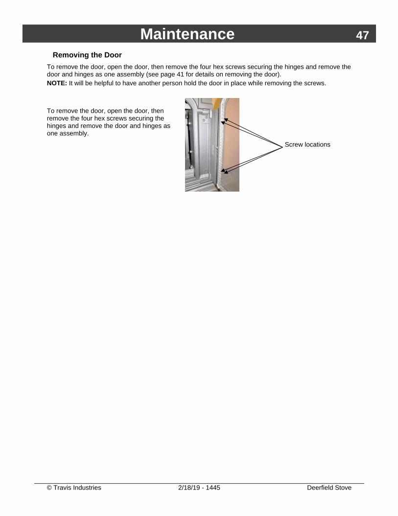
Removing the Door To remove the door, open the door, then remove the four hex screws securing the hinges and remove the door and hinges as one assembly (see page 41 for details on removing the door). NOTE: It will be helpful to have another person hold the door in place while removing the screws. To remove the door, open the door, then remove the four hex screws securing the hinges and remove the door and hinges as one assembly.
Screw locations
48 Maintenance
© Travis Industries 2/18/19 - 1445 Deerfield Stove
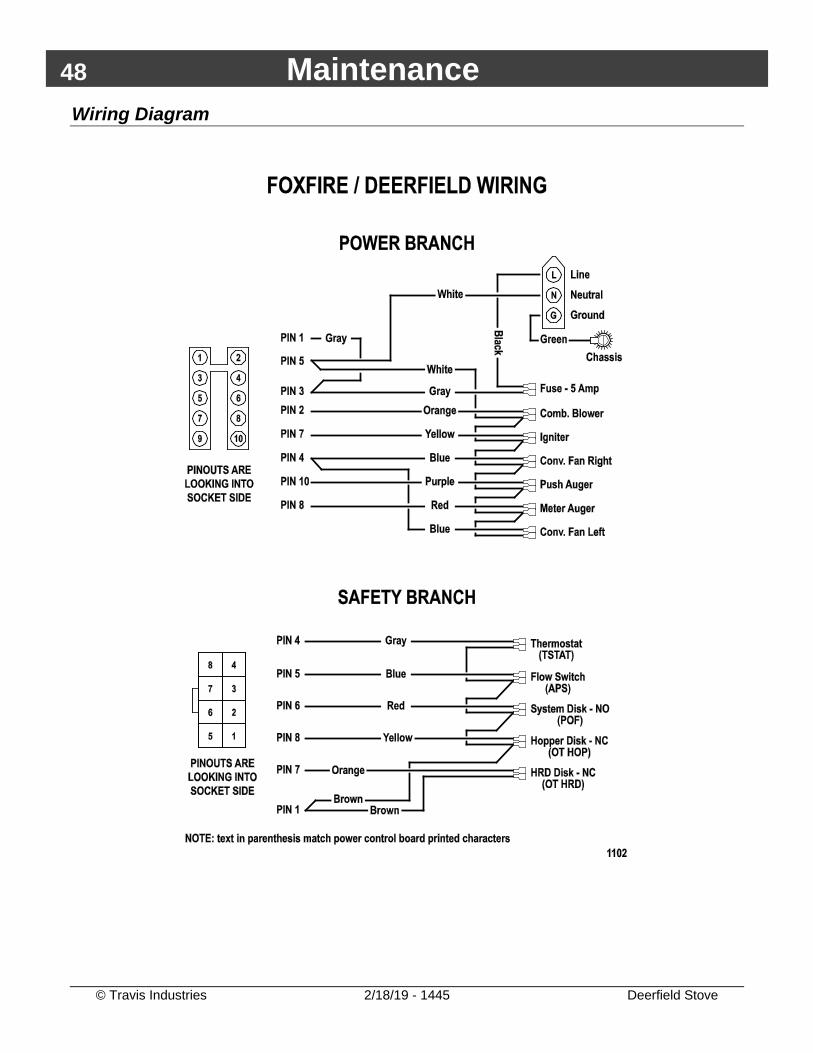
Wiring Diagram
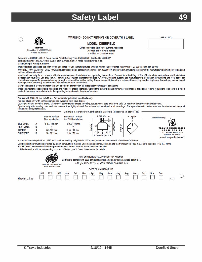
Safety Label 49
© Travis Industries 2/18/19 - 1445 Deerfield Stove
50 Limited 7 Year Warranty
© Travis Industries 2/18/19 - 1445 Deerfield Stove
Register your TRAVIS INDUSTRIES, INC. Limited 7 Year Warranty online at traviswarranty.com. TRAVIS INDUSTRIES, INC. warrants this gas appliance (appliance is defined as the equipment manufactured by Travis Industries, Inc.) to be defect-free in material and workmanship to the original purchaser from the date of purchase as follows:
Check with your dealer in advance for any costs to you when arranging a warranty call. Mileage or service charges are not covered by this warranty. This charge can vary from store to store.
Years 1 & 2 - COVERAGE: PARTS & LABOR
Firebox Assembly: Fire platform, Fire platform Holder, Ash Cleanout Doors, Ash box or Ash Dump, Heat Exchanger Tubes, Exhaust Manifold, Exhaust Box Door Assembly: Door Frame, Latch Assembly, Glass Retainers
Auger Assembly: Auger Flight, Auger Tube, Auger Bushings, HRD
Ceramic Glass Glass (breakage from thermal shock) Igniter System Igniter, Igniter Leads Electrical System Auger Motor, Convection Blower, Exhaust Blower, Circuit Board, Snap Disks, Wiring Harness, Vacuum Switch
Re-Installation Allowance In cases where heater must be removed from home for repairs, a partial cost of re-installation is covered (pre-authorization required)
One-Way Freight Allowance One-way freight allowance on pre-authorized repair done at factory is covered.
Exclusions: Paint, Gasketing, Chisel Years 3 through 5 - COVERAGE: PARTS & LABOR
Firebox Assembly: Fire platform, Fire platform Holder, Ash Cleanout Doors, Ash box or Ash Dump, Cast Fireback, Heat Exchanger Tubes, Exhaust Manifold, Exhaust Box
Door Assembly: Door Frame, Latch Assembly, Glass Retainers Auger Assembly Auger Flight, Auger Tube, Auger Bushings, HRD
One-Way Freight Allowance One-way freight allowance on pre-authorized repair done at factory is covered.
Exclusions: Paint, Gasketing, Chisel, Ceramic Glass, Igniter System, Electrical System, Cast Iron Parts, Accessories, Re-Installation Allowance Years 6 & 7 - COVERAGE: PARTS ONLY
Firebox Assembly: Fire platform, Fire platform Holder, Ash Cleanout Doors, Ash box or Ash Dump, Heat Exchanger Tubes, Exhaust Manifold, Exhaust Box
Door Assembly: Door Frame, Latch Assembly, Glass Retainers
Exclusions: Paint, Gasketing, Chisel, Ceramic Glass, Igniter System, Electrical System, Auger Assembly, HRD, Re-Installation Allowance, One-Way Freight Allowance, Labor
CONDITIONS & EXCLUSIONS 1. This new appliance must be installed by a qualified installer. It must be installed, operated, and maintained at all times in accordance with the instructions
in the Owner’s Manual. Any alteration, willful abuse, accident, neglect, or misuse of the product shall nullify this warranty. 2. This warranty is nontransferable, and is made to the ORIGINAL purchaser, provided that the purchase was made through an authorized Travis dealer. 3. Discoloration and some minor expansion, contraction, or movement of certain parts and resulting noise, is normal and not a defect and, therefore, not
covered under warranty. 4. The warranty, as outlined within this document, does not apply to the chimney components or other Non-Travis accessories used in conjunction with the
installation of this product. If in doubt as to the extent of this warranty, contact your authorized Travis retailer before installation. 5. Travis Industries will not be responsible for inadequate performance caused by environmental conditions such as nearby trees, buildings, roof tops, wind,
hills or mountains or negative pressure or other influences from mechanical systems such as furnaces, fans, clothes dryers, etc. 6. This Warranty is void if:
a. The unit has been operated in atmospheres contaminated by chlorine, fluorine or other damaging chemicals. b. The unit is subject to submersion in water or prolonged periods of dampness or condensation. c. Any damage to the unit, combustion chamber, heat exchanger or other components due to water, or weather damage which is the result of, but not
limited to, improper chimney/venting installation. 7. Exclusions to this 7 Year Warranty include: injury, loss of use, damage, failure to function due to accident, negligence, misuse, improper installation, alteration or
adjustment of the manufacturer's settings of components, lack of proper and regular maintenance, damage incurred while the appliance is in transit, alteration, or act of God.
8. This 7 Year warranty excludes damage caused by normal wear and tear, such as paint discoloration or chipping, worn or torn gasketing, chipped or cracked firebrick, etc. Also excluded is damage to the unit caused by abuse, improper installation, modification of the unit, or the use of fuel other than that for which the unit is configured.
9. Damage to gold or nickel surfaces caused by fingerprints, scratches, melted items, or other external sources left on the gold or nickel from the use of cleaners other than denatured alcohol is not covered in this warranty.
10. TRAVIS INDUSTRIES, INC. is free of liability for any damages caused by the appliance, as well as inconvenience expenses and materials. Incidental or consequential damages are not covered by this warranty. In some states, the exclusion of incidental or consequential damage may not apply.
11. This warranty does not cover any loss or damage incurred by the use or removal of any component or apparatus to or from the Travis appliance without the express written permission of TRAVIS INDUSTRIES, INC. and bearing a TRAVIS INDUSTRIES, INC. label of approval.
12. Any statement or representation of Travis products and their performance contained in Travis advertising, packaging literature, or printed material is not part of this 7 year warranty.
13. This warranty is automatically voided if the appliance’s serial number has been removed or altered in any way. If the appliance is used for commercial purposes, it is excluded from this warranty.
14. No dealer, distributor, or similar person has the authority to represent or warrant Travis products beyond the terms contained within this warranty. TRAVIS INDUSTRIES, INC. assumes no liability for such warranties or representations.
15. Travis Industries will not cover the cost of the removal or re-installation of hearths, facing, mantels, venting or other components. 16. If for any reason any section of this warranty is declared invalid, the balance of the warranty remains in effect and all other clauses shall remain in effect. 17. This 7 year warranty is the only warranty supplied by Travis Industries, Inc., the manufacturer of the appliance. All other warranties, whether express or
implied, are hereby expressly disclaimed and purchaser’s recourse is expressly limited to the warranties set forth herein.
Limited 7 Year Warranty 51
© Travis Industries 2/18/19 - 1445 Deerfield Stove
IF WARRANTY SERVICE IS NEEDED: 1. If you discover a problem that you believe is covered by this warranty, you MUST REPORT it to your Travis dealer WITHIN 30 DAYS, giving
them proof of purchase, the purchase date, and the model name and serial number. 2. Travis Industries has the option of either repairing or replacing the defective component. 3. If your dealer is unable to repair your appliance’s defect, he may process a warranty claim through TRAVIS INDUSTRIES, INC., including the
name of the dealership where you purchased the appliance, a copy of your receipt showing the date of the appliance’s purchase, and the serial number on your appliance. At that time, you may be asked to ship your appliance, freight charges prepaid, to TRAVIS INDUSTRIES, INC. TRAVIS INDUSTRIES, INC., at its option, will repair or replace, free of charge, your appliance if it is found to be defective in material or workmanship within the time frame stated within this 7 year warranty. TRAVIS INDUSTRIES, INC. will return your appliance, freight charges (years 1 to 5) prepaid by TRAVIS INDUSTRIES, INC., to your regional distributor, or dealership.
4. Check with your dealer in advance for any costs to you when arranging a warranty call. Mileage or service charges are not covered by this warranty. This charge can vary from store to store.
52 Index
© Travis Industries 5/7/19 - 1445 Deerfield Stove
Alcove Installation Requirements ..................... 14 Before You Begin ............................................... 8 Check for Air Leaks .......................................... 41 Checking the Ashpan ....................................... 40 Chisel Replacement ......................................... 45 Clean the Burn platform ................................... 34 Clean the Convection Blower ........................... 43 Clean the Firebox Liners .................................. 37 Clean the Glass ................................................ 39 Clean the Lower Exhaust Duct ........................ 42 Clean the Vent ................................................. 45 Clearances ....................................................... 10 Corner Installations .......................................... 10 Curing the Paint ............................................... 23 Dimensions ........................................................ 7 Disposing Ashes .............................................. 32 Door Adjustment .............................................. 41 Door and Glass Inspection ............................... 41 Efficiency ............................................................ 7 Electrical Specifications ..................................... 7 Emissions ........................................................... 7 Fan Setting ....................................................... 28 Floor Protection Requirements .......................... 9 Fuel .................................................................... 7 Heater Status ................................................... 29 Heating Specifications ........................................ 7 Important Information ......................................... 2 Inspect the Burn ............................................... 34 Installation Example: Direct "Through-the-wall"
Installation .................................................... 16 Installation Example: Freestanding Masonry
Chimney ....................................................... 21 Installation Example: Interior Vertical Installation
...................................................................... 17 Installation Example: Masonry Fireplace Hearth
Stove ............................................................. 19
Installation Example: Zero-Clearance (Metal) Fireplace Hearth Stove ................................ 20
Installation Options ............................................ 8 Installing the Pellet Vent .................................. 12 Introduction ........................................................ 2 Loading Pellets ................................................ 23 Manual Mode ................................................... 25 Maximum Venting Distance ............................. 11 Menu Button ..................................................... 30 Mobile Home Requirements ............................ 13 Modes of Operation – Manual or Thermostat .. 24 Monthly Maintenance ........................................ 41 Opening the Door ............................................. 33 Packing List ........................................................ 8 Pellet Vent Termination ................................... 12 Pellet Vent Type ............................................... 12 Planning the Installation ..................................... 9 Power Outages ................................................ 31 Removing the Door .......................................... 47 Replacing the Door Gasket .............................. 46 Replacing the Door Handle .............................. 46 Replacing the Glass ......................................... 46 Restrictor Adjustment ...................................... 14 Safety Notice .................................................... 22 Starting the Heater for the First Time .............. 23 Stove Maintenance .......................................... 32 Stove Maintenance Tools ................................ 33 Stove Placement ................................................ 9 Straight Installations ........................................ 10 Thermostat (T-Stat) Mode ............................... 26 Thermostat Programs ...................................... 27 Touch Screen Controls .................................... 22 Venting the Pellet Stove .................................. 11 Yearly Maintenance - Clean the Negative
Pressure Tube .............................................. 44
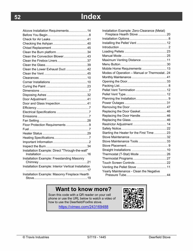
Want to know more?
Scan this code with a QR reader on your cell phone or use the URL below to watch a video of how to use the Deerfield/Foxfire stove.
https://vimeo.com/243169488