
MOMENT-ROTATION CHARACTERISTICS AND FINITE ELEMENT ...
18
Uludağ University Journal of The Faculty of Engineering, Vol. 26, No. 1, 2021 RESEARCH DOI: 10.17482/uumfd.798136 29 MOMENT-ROTATION CHARACTERISTICS AND FINITE ELEMENT ANALYSIS OF COLD FORMED STEEL CONNECTIONS Fatih ALEMDAR * Hunde Dechasa GELETA ** Fuad Mohammed ALGAADİ ** Received: 21.09.2020; revised: 14.12.2020; accepted: 18.01.2021 Abstract: The connections are used to transfer forces and moments due to applied loading. The capability of the connection in the resisting moment is used to classify the types of connections in steelwork particularly for cold-formed steel. Classification schemes based on the total moment-rotation behavior have been developed to aid in the design and analysis of connections. Moment-rotation curve commonly used to describe the connection behavior that can be obtained from either theoretical or experimental study. It is often inappropriate to define the connections as either rigid or pinned due to their high non-linear behavior. Therefore, the lightweight cold formed steel connections have been classified into simple, semi-rigid, and rigid connections according to their strength and rigidity, and discussed in detail. Three-dimensional finite element model of lightweight cold formed steel connection under cyclic loading was generated to investigate and study their behavior. Two lipped sigma sections back-to-back with interconnections are used as beam and column members. Finally, the connection type of lightweight cold formed steel connections have been found to be as semi-rigid, and the key factors influencing stiffness is the bearing forces around the bolt hole. Keywords: Finite element analysis, moment-rotation, cold-formed steel, rigidity Soğuk Şekillendirilmiş Çelik Bağlantilarin Moment-Dönme Özellikleri ve Sonlu Eleman Analizi Öz: Bağlantılar uygulanan yükleme nedeniyle kuvvetleri ve momentleri aktarmak için kullanılır. Taşıma momenti etkisindeki bağlantının kapasitesi, özellikle soğuk şekillendirilmiş çelik için çelik yapıdaki bağlantı türlerini sınıflandırmak için kullanılır. Bağlantının tasarımına ve analizine yardımcı olmak için toplam moment-eğrilik davranışına dayalı sınıflandırma şemaları geliştirilmiştir. Moment -dönme eğrisi, genellikle teorik veya deneysel çalışmadan elde edilebilecek bağlantı davranışını tanımlamak için kullanılır. Doğrusal olmayan davranışlarının yüksek olması nedeniyle bağlantıları ankastre veya sabit olarak tanımlamak genellikle uygunsuzdur. Bu nedenle, soğuk şekillendirilmiş çelik bağlantılar, mukavemetlerine ve rijitliklerine göre basit, yarı rijit ve rijit bağlantılar olarak sınıflandırılmış ve ayrıntılı olarak tartışılmıştır. Çevrimsel yükleme altında soğuk şekillendirilmiş çelik bağlantıların davranışlarını incelemek için üç boyutlu sonlu eleman modelleri oluşturulmuştur. Kiriş ve kolon elemanlar için sırt sırta iki sigma kesit kullanılmıştır. Son olarak, soğuk şekillendirilmiş çelik bağlantıların özelliklerinin yarı rijit olduğu ve rijitliği etkileyen anahtar faktörlerin bulon deliği etrafındaki ezilme kuvvetleri olduğu bulunmuştur. Anahtar kelimeler: Sonlu eleman analizi, moment-dönme, soğuk şekillendirilmiş çelik, rijitlik * Yıldız Teknik Üniversitesi, Davutpaşa Kampüsü, İnşaat Mühendisliği Bölümü, Esenler, İstanbul 34220 ** Yıldız Teknik Üniversitesi, Davutpaşa Kampüsü, İnşaat Mühendisliği Bölümü, Esenler, İstanbul 34220 İletişim Yazarı: Fatih ALEMDAR ([email protected])
Transcript of MOMENT-ROTATION CHARACTERISTICS AND FINITE ELEMENT ...

Uludağ University Journal of The Faculty of Engineering, Vol. 26, No. 1, 2021 RESEARCH DOI: 10.17482/uumfd.798136
29
MOMENT-ROTATION CHARACTERISTICS AND FINITE
ELEMENT ANALYSIS OF COLD FORMED STEEL
CONNECTIONS
Fatih ALEMDAR *
Hunde Dechasa GELETA **
Fuad Mohammed ALGAADİ **
Received: 21.09.2020; revised: 14.12.2020; accepted: 18.01.2021
Abstract: The connections are used to transfer forces and moments due to applied loading. The capability
of the connection in the resisting moment is used to classify the types of connections in steelwork
particularly for cold-formed steel. Classification schemes based on the total moment-rotation behavior have
been developed to aid in the design and analysis of connections. Moment-rotation curve commonly used to
describe the connection behavior that can be obtained from either theoretical or experimental study. It is
often inappropriate to define the connections as either rigid or pinned due to their high non-linear behavior.
Therefore, the lightweight cold formed steel connections have been classified into simple, semi-rigid, and
rigid connections according to their strength and rigidity, and discussed in detail. Three-dimensional finite
element model of lightweight cold formed steel connection under cyclic loading was generated to
investigate and study their behavior. Two lipped sigma sections back-to-back with interconnections are
used as beam and column members. Finally, the connection type of lightweight cold formed steel
connections have been found to be as semi-rigid, and the key factors influencing stiffness is the bearing
forces around the bolt hole.
Keywords: Finite element analysis, moment-rotation, cold-formed steel, rigidity
Soğuk Şekillendirilmiş Çelik Bağlantilarin Moment-Dönme Özellikleri ve Sonlu Eleman Analizi
Öz: Bağlantılar uygulanan yükleme nedeniyle kuvvetleri ve momentleri aktarmak için kullanılır. Taşıma
momenti etkisindeki bağlantının kapasitesi, özellikle soğuk şekillendirilmiş çelik için çelik yapıdaki
bağlantı türlerini sınıflandırmak için kullanılır. Bağlantının tasarımına ve analizine yardımcı olmak için
toplam moment-eğrilik davranışına dayalı sınıflandırma şemaları geliştirilmiştir. Moment-dönme eğrisi,
genellikle teorik veya deneysel çalışmadan elde edilebilecek bağlantı davranışını tanımlamak için kullanılır.
Doğrusal olmayan davranışlarının yüksek olması nedeniyle bağlantıları ankastre veya sabit olarak
tanımlamak genellikle uygunsuzdur. Bu nedenle, soğuk şekillendirilmiş çelik bağlantılar, mukavemetlerine
ve rijitliklerine göre basit, yarı rijit ve rijit bağlantılar olarak sınıflandırılmış ve ayrıntılı olarak tartışılmıştır.
Çevrimsel yükleme altında soğuk şekillendirilmiş çelik bağlantıların davranışlarını incelemek için üç
boyutlu sonlu eleman modelleri oluşturulmuştur. Kiriş ve kolon elemanlar için sırt sırta iki sigma kesit
kullanılmıştır. Son olarak, soğuk şekillendirilmiş çelik bağlantıların özelliklerinin yarı rijit olduğu ve
rijitliği etkileyen anahtar faktörlerin bulon deliği etrafındaki ezilme kuvvetleri olduğu bulunmuştur.
Anahtar kelimeler: Sonlu eleman analizi, moment-dönme, soğuk şekillendirilmiş çelik, rijitlik
* Yıldız Teknik Üniversitesi, Davutpaşa Kampüsü, İnşaat Mühendisliği Bölümü, Esenler, İstanbul 34220 ** Yıldız Teknik Üniversitesi, Davutpaşa Kampüsü, İnşaat Mühendisliği Bölümü, Esenler, İstanbul 34220
İletişim Yazarı: Fatih ALEMDAR ([email protected])

Alemdar F.,Geleta H.D., Algaadi F.M.: Cold Form Steel Connection
30
1. INTRODUCTION
Due largely to the wider variety of structural applications relative to a conventional heavy
hot-rolled steel structural members, lightweight cold formed steel (CFS) has exhibiting a growing
use as a frame structure in the multi-story commercial and residential buildings in the last two
decades. Their lightweight, strength, flexibility, and production ease have enabled architects,
contractors, and professionals in the field to use products of cold formed lightweight steel that
will increase building performance and structural efficiency. At the same time, cold formed
lightweight steel members have particular stability problems largely because of the larger width-
thickness ratio that is not widely found in the hot rolled steel sections (Rondal, 2000; Davies,
2000; Gotluru, 2000). Simple geometric analyses, finite element analyses and finite strip analyses
were performed in order to investigate the torsional and distortional behavior of cold formed
sections and compared with experimental results (Gotluru, 2000; Put, 1999; Jönsson, 1999).
The hot rolled steel is produced and formed at a high temperature, but cold formed one is at
room temperature. A mechanism of producing cold steel members is by shaping the material using
either the technique of cold roll forming or the technique of press breaking to get the desired
shapes. A cold-formed structural steel member is usually manufactured from strip material, sheet
metal, or steel plates (Yu et al., 2020).
The cold formed steel systems have diverse welded and bolted connections. Bolted
connections are often applied in building sites because they are easier to build. Rogers and
Hancock (1999a) studied to improve the design rules for bolted and screwed connections. Failure
modes of these types of connections were investigated (Rogers and Hancock, 1999b; Rogers and
Hancock, 2000; Bolandim et al., 2013; Liu et al., 2014Yu and Xu, 2013). In the column to beam
joint or overlapped system, gusset plates are the mostly used bolted connecting solution (Tan et
al., 2013; Ye et al., 2016). The use of gusset plate can be enhanced by integrating the use of bolted
flange-cleat beam-to-column joints in order to achieve a connection considered as simple, fast,
cost-effective, and of high quality (Rahbari, 2014). A bolted gusset-plate joint for CFS section
was proposed by Bucmys (2015) and the behavior of rectangular gusset plates in CFS connections
for beam-column connection with double C-channel (Bucmys, 2017).
The reviews on the development of the cold formed steel members have been significantly
increased in the recent years. The reviews focused on the behavior of the cold formed steel
sections such as compression of members, distortion and element buckling, curved and corrugated
sheets, distortion and torsion, web crippling, construction of plasterboards and composites, and
design optimization. The majority of the studies utilized some analytical approximations and
purely numerical methods. EN 1993-1-3 standard (2006) and AISI S100 (2007) specification
include analytical approximation methods to assess the structural behavior of cold formed steel
members. Some numerical methods such as finite element method and finite strip method are
used by commercial and free softwares.
The efficiency of the cold-formed steel frames was investigated by a limited number of
researchers. Kwon et al. (2006) presented a portal frame connection and system tests consisting
of cold-formed parts. Researches indicated that semi-rigid connections formed have large
efficiency and can be employed effectively (Kwon et al., 2006). Approaches to strengthening top
chords to avoid local buckling were examined (Dawe and Wood, 2006). Raftoyiannis I.G (2005)
created an analysis of linear stability to assess the influence of the flexibility of the joint.
Numerical results showed the influence on the buckling load by two-parameter successfully in
the graphical and tabular form (Raftoyiannis, 2005). Tan S.H (2001) offered nonlinear analysis
using an analytical model and thin-walled channels frame experiments having the various
configuration of connections. It was necessary to reach a closure among the experimental and
theoretical findings. Testing showed that the influence of the thickness of the connection on the
Uludağ University Journal of The Faculty of Engineering, Vol. 26, No. 1, 2021
31
rigidity of the cold formed steel frames is less important relative to the lip sizes and thickness of
the members (Tan, 2001).
To improve the technical application of cold formed steel studies, research into the structural
behavior and performance of such frames is still required. A steel frame's structural response is
intimately linked to the behavior of its connections (Hancock et al., 2001). In this study, the
column and the beam elements are made from a section of double sigma. The material properties
of lightweight cold formed steel are utilized as inelastic and connections are defined with bolts.
The performance of the connection is examined using computer simulation and found to be semi-
rigid. Finally, the key factor influencing stiffness is obtained to be the bearing forces around the
bolt hole.
2. COLD-FORMED STEEL CONNECTION TYPES BASED ON RIGIDITY
Connections are categorized by ductility and strength, in which ductility is related to the
plastic rotation capacities before failure. The connections’ strength category depend on the
moment resistance of the beams in the connections. For a connection, rotational capacity and
strength are essential parameters. A full-strength connection designed by a plasticity principle can
be considered to demonstrate the significance of both strength and rotational flexibility in
connections. In this condition, one potential problem may occur when the beam's yield stress
exceeds the specific values.
The stability and efficiency of the cold formed steel lightweight structure will be influenced
by beam-column connections. A connection transfers force and moment from beam to column.
The connections are subjected to axial force, bending moment, shear force, and torsional
moments. Compared to bending moment, the torsion effect might be left out, and axial and shear
forces can be too minimal. The connections are used to transfer forces and moments due to applied
loading. The capacity of the connection in resisting moment will be used to classify the type of
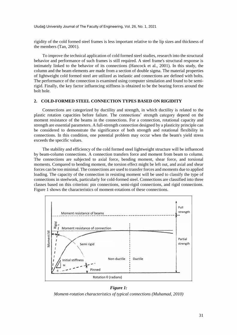
connections in steelwork, particularly for cold-formed steel. Connections are classified into three
classes based on this criterion: pin connections, semi-rigid connections, and rigid connections.
Figure 1 shows the characteristics of moment-rotations of these connections.
Figure 1:
Moment-rotation characteristics of typical connections (Muhamad, 2010)

Alemdar F.,Geleta H.D., Algaadi F.M.: Cold Form Steel Connection
32
2.1. Pin Connection
A pin connection in steel structures is the simplest form of the connection. The kind of
connection is used only to withstand shear and normal force. It does not have any moment restraint
at the connection. A pin connection is one of those connections that provide zero rotational
restraint. In design, it is assumed that pin connections transfer only shear force, from beams to
the columns next to a nominal moment and axial load. That means members with a pin connection
can rotate freely when the load is applied. The member is supposed to be simply supported when
designing pin connections, and caution should be taken in construction so as not to give extra
strength to the connection, as the column may fail from buckling due to the extra moment
transferred to it.
2.2. Semi-Rigid Connection
In practice, the connection often falls into pin and rigid categories although designing pin or
rigid connections is common. The majority of the connection does not fall into these two
categories because it is hard to maintain this idealized situation, where either there should be no
relative rotation for the rigid connections, and no moment is transferred in the pin connections.
Most connections transfer some bending moments, and to some degree, rotation occurs. These
kinds of connections are called semi-rigid connections, or partial strength connections. The end
joints of the member are allowed to rotate but the rotation would be limited. This semi-rigid
connection is designed to have an expected interaction degree among the members depending on
a joint's moment-rotations behavior.
Connections in semi-rigid category have partial strength and ductility. Generally, the
connection can be categorized as ductile, if the maximum rotation is greater than 0,003 radians
under the maximum moment. This minimum is increased to 0,004 radians in the seismic zone of
a special moment frame since greater ductility is desired (Chen, 2000).
2.3. Rigid Connection
Rigid connections are connections with high rigidity that are adequate to preserve the original
angle between the intersecting members under the design load. Often known as a full-restraint
connection, a rigid connection is able to restrain a moment at the connection. There will be no
member rotation at the joint. Rigid connections are designed to be fully restrained, in which
ideally there should be no rotation between the connected members. For this connection, full
continuity of the connection is preserved where the moment of bending is fully transferred from
the beam to the column, along with shear and axial force.
3. MOMENT-ROTATION (M-ϕ) CHARACTERISTICS
The moment-rotation curve typically used to describe a connection's behavior can be
obtained through either theoretical procedure or experimental research. As their behavior is often
highly non-linear, the classification of a connection as either rigid or pinned is often inappropriate.
In the literature, numerous classification schemes were developed based on the total moment-
rotation behavior to aid in connection design and analysis. Most of these schemes classify a
connection into the following three basic categories according to its moment-rotation
characteristic which are flexible, rigid, and semi-rigid.
Semi rigidity concept was known for decades, however, the reason why the term is not used
regularly in the frame’s practical layout is that its modeling is hard. In a semi-rigid connection,
one of the main elements is the moment rotation curve. For other types of connections, the
importance of this curve is negligible. For example, a rigid connection is modeled in a beam-

Uludağ University Journal of The Faculty of Engineering, Vol. 26, No. 1, 2021
33
column connection by setting the boundary conditions such that there is no relative rotation
between the column and beam, while in the pin connection, a beam is assumed to be free to rotate
from the column. The response is somewhere in between those two scenarios for semi-rigid
frames and therefore the moment-rotation curve is so important.
The rotations rise faster for small moment values than large values. The nonlinear behavior
is mainly because of connections component’s local yield, as well as discontinuities of materials,
the concentration of stress, and change in geometry under a loading. The nonlinear behavior may
exacerbate in some connection types, particularly in bolt connections, in which slips may cause
larger rotations than the one that occurs due to a moment (Chen and Kim, 1989).
Initial stiffness Rki is the main parameter of a moment-rotation curve, that is the initial slope
of the curve. Unloading stiffness, Rku, is a result of load removals or reversals. The tangent
stiffness, Rkt, is an immediate stiffness that falls with increasing moments. The secant stiffness,
Rks, is an effective stiffness of the connection. All these parameters are shown in Figure 2.
Figure 2:
Moment-Rotation Curve (Leigh, 2006)
A number of different methods can be used to get this moment-rotation curve. One approach
is using experimental results. Care should be given to make sure if the condition of a test is exact
representations of the design. In converting empirical data of moment rotations to the design
values, it is important to use the technique of curve-fitting that approximates a real curve. An
equation of the curve approximately is given:
M = 𝑅𝑘𝑖 𝑋 𝜃
[1+(𝜃
𝜃0)𝑛]
1𝑛
(1)
where 𝜃0 is the reference rotation, 𝑅𝑘𝑖 is the connection’s initial stiffness and n is the shape factor
(Chen, 2000).
Many connections exhibit nonlinear behavior at small values of moment-rotation right from
the start. Usually, the very first tangents at points of zero moment-rotation values give an ideally
Alemdar F.,Geleta H.D., Algaadi F.M.: Cold Form Steel Connection
34
larger initial definition of the stiffness under service level load. Secant stiffness thus can be
considered as the index for defining the initial stiffness of the connection. The secant stiffness
defined as Ks = Ms θs⁄ at the service load where 𝑀𝑠 is the moment and θs is the rotation under
the service load. The connection rigidity is classified as given in Table 1. The 𝜆 is the ratio of the
connection secant stiffness to the beam flexural rigidity,
𝜆 =𝐾𝑠 (𝐸𝐼 𝐿⁄⁄ ) (2)
L is the length of the beam, and EI is the flexural rigidity of the beam.
Table 1. Connection classification according to the stiffness
Connection Stiffness
Pin 𝜆 ≤ 2
Semi rigid 2 < 𝜆 < 20
Rigid 𝜆 ≥ 20
The values from 2 to 20 of λ indicate the stiffness level of a connection. The connection is
more flexible as it approaches 2. Likewise, the connection gets stiffer as it gets closer to 20.
An alternative approach to the empirically obtained M- θ curve is the finite element analysis
of the connection model. The advantage of the finite element approach is that there's no need to
use costly materials and laboratory time. Another advantage is that the model parameters are
quickly modifiable, and the actual detail of the connection could be simulated. The disadvantage
of the finite element method is that it needs higher levels of knowledge of the simulation of finite
element and it consumes time. For the welded connection finite element approach is suitable,
however; particularly for the bolted connections it is difficult because bolt has high complexity
and variability. For example, the holes of a bolt in plates compared to the diameters of the bolt
can be larger in the extents that permit more rotations than expected with a geometric lack of fit
(Narayanan, 1989).
4. FINITE ELEMENT MODEL
Three-dimensional finite element analysis of lightweight cold formed steel connections
under cyclic loading was studied. In this study, ABAQUS finite element program was adopted
for the numerical simulation of lightweight cold formed steel connections, as shown in Figure 3.
Laboratory testing although play an important role in determining the structural behavior, findings
from the simulation of finite element may provide more detailed stress and strain analysis. In
ABAQUS modeling process, the connection dimensions, boundary conditions, and material
properties used as similar as possible to the experimental set-up model to increase the accuracy.
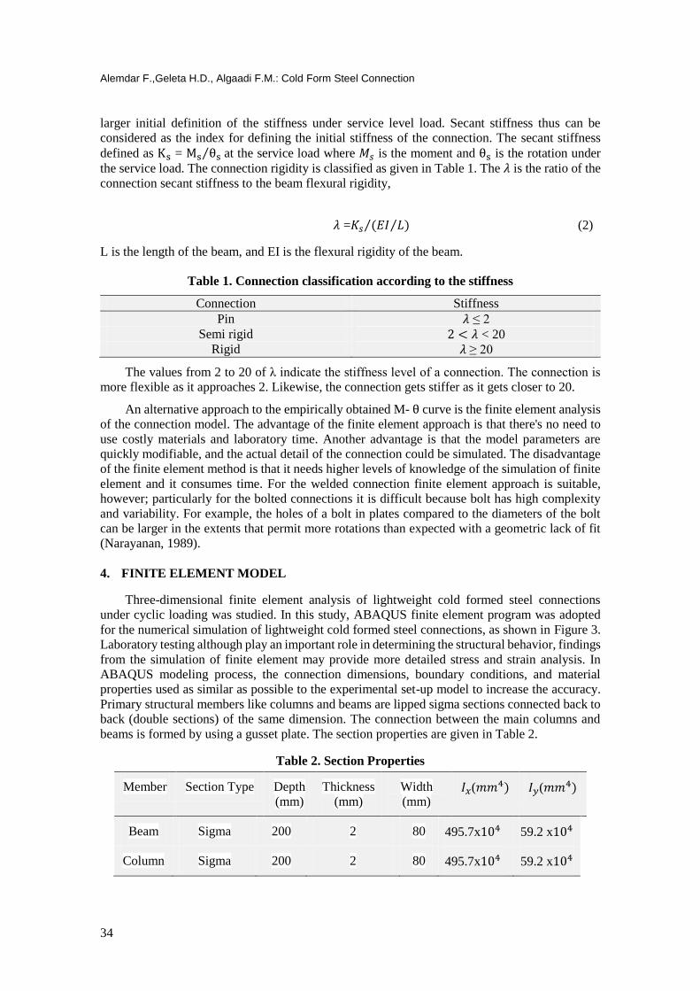
Primary structural members like columns and beams are lipped sigma sections connected back to
back (double sections) of the same dimension. The connection between the main columns and
beams is formed by using a gusset plate. The section properties are given in Table 2.
Table 2. Section Properties
Member Section Type Depth
(mm)
Thickness
(mm)
Width
(mm) 𝐼𝑥(𝑚𝑚4) 𝐼𝑦(𝑚𝑚4)
Beam Sigma 200 2 80 495.7x10⁴ 59.2 x10⁴
Column Sigma 200 2 80 495.7x10⁴ 59.2 x10⁴

Uludağ University Journal of The Faculty of Engineering, Vol. 26, No. 1, 2021
35
4.1. Modeling The Structure
The finite element method (FEM) is the leading process in discretization for structural
mechanics. Within the physical definition of the FEM, the fundamental principle is that the
splitting of a model into a simple geometry non overlapping component known as finite element
or element shortly. Separating members into a network of finite elements is one of the most critical
steps towards converging into the real behavior of the structure. The response of each element is
described in terms of the finite number of degree of freedoms defined at a nodal point as a value
of an unknown function.
The unknown is defined by every degree of freedom of the node in the mesh of finite element.
In the analysis of the structure nodal degree of freedoms describe components of displacements
whereas they describe temperatures in the analysis of heat. The key unknown in the analysis of
structure and heat analysis is nodal displacements and nodal temperatures, respectively.
A detailed finite element model was developed to investigate the structural performance of
cold formed steel connections under cyclic loading. The model developed takes into consideration
the effects of geometric imperfections and nonlinearity of the materials. A full three-dimensional
column-beam connection was modeled in ABAQUS (2015) to better understand the detailed
structure characteristics as shown in Figure 3. Details of the connection parts are given in Figure
4.
Figure 3:
Model developed in ABAQUS

Alemdar F.,Geleta H.D., Algaadi F.M.: Cold Form Steel Connection
36
(a) (b)
Figure 4:
(a) Typical column-beam connection, (b) Typical gusset plate
4.2. Defining Material and Geometric Properties
Incorporating an accurate description of material behavior is essential to develop reliable
finite element models. Inappropriate material behavior representation can severely influence the
result extracted from a FEM. In this study, isotropic properties of steel material are assigned to
the elements. The modulus of elasticity and Poisson's ratio have been taken, respectively, as 210
GPa and 0.3. The density of 7.86 X 10⁻⁹ ton/𝑚𝑚3 is defined. Material characteristics of the cold
formed steel used in the model have been determined from tensile testing results of specimens in
the laboratory. Figure 5 indicates the average stress-strain relationship used in finite element
analysis.
The major components of the steel frame are modeled to reflect the actual behavior of the
cold formed steel connection including column, beam, and, gusset plates. A four node nonlinear
shell element having reduced integrations points (to reduce the computational cost) was used in
the model. A stress–strain curve is the main steel property used to describe its behavior. The
stress-strain behavior of cold formed steel is different from that of hot-rolled steel. The yield stress
and the ultimate yielding stress are 250 MPa and 375 MPa, respectively.
Figure 5:
Stress-strain diagram
0
50
100
150
200
250
300
350
400
450
0 0,05 0,1 0,15 0,2 0,25 0,3
Str
ess
(MP
a)
Strain (mm/mm)

Uludağ University Journal of The Faculty of Engineering, Vol. 26, No. 1, 2021
37
4.3. Meshing The Structure
The accuracy in the finite element models is directly related to the mesh used. The mesh in
the finite element is often used to divide the model into a smaller domain known as the element
that solves the series of equation. Such kinds of equations represent governing equations of
interest through the sets of polynomial functions defined in those elements approximately. The
simulated solution approaches the true solution as the elements are produced in small size or
refined meshing. On the other hand, the expense of computing rises with the rise in the fineness
of the mesh. The optimal density of a mesh was calculated through the convergence analysis,
which allows a balance between the accuracy and the cost of the solution. In the FE model of the
connection, the near-joint regions are created with a finer mesh. It has been found that 25 x 25
mm mesh size for the beam and column and the 10 x 10 mm mesh size around the connection
provide more accurate results and the computational time is not significantly increased. Figure 6
shows the meshed finite element model of the beam-column subassembly.
Figure 6:
Finite Element Mesh
4.4. Contact Definitions between Element Surfaces
Definition of the interaction between the surfaces of the elements directly affects the
analytical results. In the actual connections, the connection of the column, beam, and gusset plate
are made using the M12 bolts as shown in Figure 4. In this research, simplifications are made as
much as possible while creating the models of the connections. Tie constrain is defined at the
interaction of bolts with gusset plate, beam, and column. In this way, it is thought that more
accurate results can be obtained. Structural analysis often considers the interaction between two
objects. One of these two objects is called master surfaces, another one is called slave surfaces.
A surface-to-surface contact command of ABAQUS/Standard is used to define interaction among
connection’s component. Two surfaces are paired which can interact with each other; one of the
surfaces is assigned to be the master surface, and the other is assigned to be the slave surface. In
ABAQUS/Standard algorithm of the masters-slaves recognizes a contact surface and apply
constraint (pressures) on the slave node to protect them from penetration into the master surfaces.
An edge-to-edge contact element is the kind of element that transfers contact stress over the
restricted area by mutually decreasing the edge element node points that fit this element to any
edge element selected on the contact surface. The contact element is the element that transfers

Alemdar F.,Geleta H.D., Algaadi F.M.: Cold Form Steel Connection
38
contact stress to the edge of the projection element of a node selected on the contact surface.
Contact direction occurs toward the directions of the master surface. The contact surfaces are
limited, then the master surface is not penetrated. However, master surfaces will in principle be
in contact with the contact surface. Additionally, while surface-to-surface contact mechanics have
been established, objects that appear to penetrate to the surface at corner node points where they
touch. In current models, the surfaces required to interact with each other include the surfaces of
gusset plates, beams, and columns where the bolt lies as shown in Figure 7.
Figure 7:
Contact definition column-gusset plate
4.5. Loading and Boundary Conditions
Boundary conditions in the simulation domain are necessary when implementing FEM.
Remembering that the finite element approach is basically a numerical approach to solve certain
kinds of differential equations called boundary value problems. Column end surfaces were
defined as pinned whereas beam end section was constrained in all directions except in vertical
direction. Nonlinear finite element analysis was carried out using Static General module by the
application of the displacements at a reference point placed on the end sections of the beam as
shown in Figure 8. In accordance with FEMA-350 (2000), Table 3 provides the cyclic loading
details.
One of the challenges in the nonlinear structural analysis is that the structural rigidity changes
as the deformation occurs. Three nonlinearities sources are common in structure modeling. Two
of them are material and geometric nonlinearities. The third nonlinearity source is the nonlinearity
of the boundary correlated to the boundary condition change in the analysis.
In this study, the General static analysis was employed using displacements controls.
ABAQUS/Standard make uses of the method of Newton-Raphson to solve a problem involving
nonlinearity. The solution is found in a nonlinear analysis by using the application of displacement

Uludağ University Journal of The Faculty of Engineering, Vol. 26, No. 1, 2021
39
or load in the increment until the last solutions are achieved. The approximate solution is to sum
up all these increments.
Figure 8:
Loading the Structure and Boundary Conditions
The SAC Joint Venture (SAC), that is supported by the Federal Emergency Management
Agency (FEMA), was founded by the Applied Technology Council (ATC), the California
Universities for Research in Earthquake Engineering (CUREE), and the Structural Engineers
Association of California (SEAOC) in the middle of 1994 in order to examine the damages in the
welded steel buildings during the Northridge Earthquake of 1994, and develop maintenance
strategies and innovative approach of design in order to reduce damages in the future earthquakes
(Lee and Foutch, 2000).
Table 3.Protocol of cyclic loading (FEMA-350)
Load Step Peak
deformation(rad)
Number of cycles
1 0.00375 6
2 0.005 6
3 0.0075 6
4 0.01 4
5 0.015 2
6 0.02 2
7 0.03 2
8 0.04 2
9 0.05 2
4.6. Result Interpretation
The criterion of Von Mises Stress failure depends on the Von Mises principle and called the
principle of the maximum theory of energy distortion or scalar energy. It is most widely used
failure criterion. The theory notes that when a Von Mises Stress at a location equals a stress limit
the ductile material begins yielding. The yielding strength is used mostly as limit stress. In the
uniaxial result of tensile tests, under complicated loading conditions, a Von Mises Stress can be
used to determine yielding of the material. A greater Von Mises value means the material is nearer
to the yield point. Von Mises Stress is the measure of non-negative, scalar stresses. Due to the
Alemdar F.,Geleta H.D., Algaadi F.M.: Cold Form Steel Connection
40
fact that many engineering materials exhibit elastoplastic behavior (i.e. steel and aluminum alloy)
the members made of such materials can be analyzed by the use of Von Mises Stress.
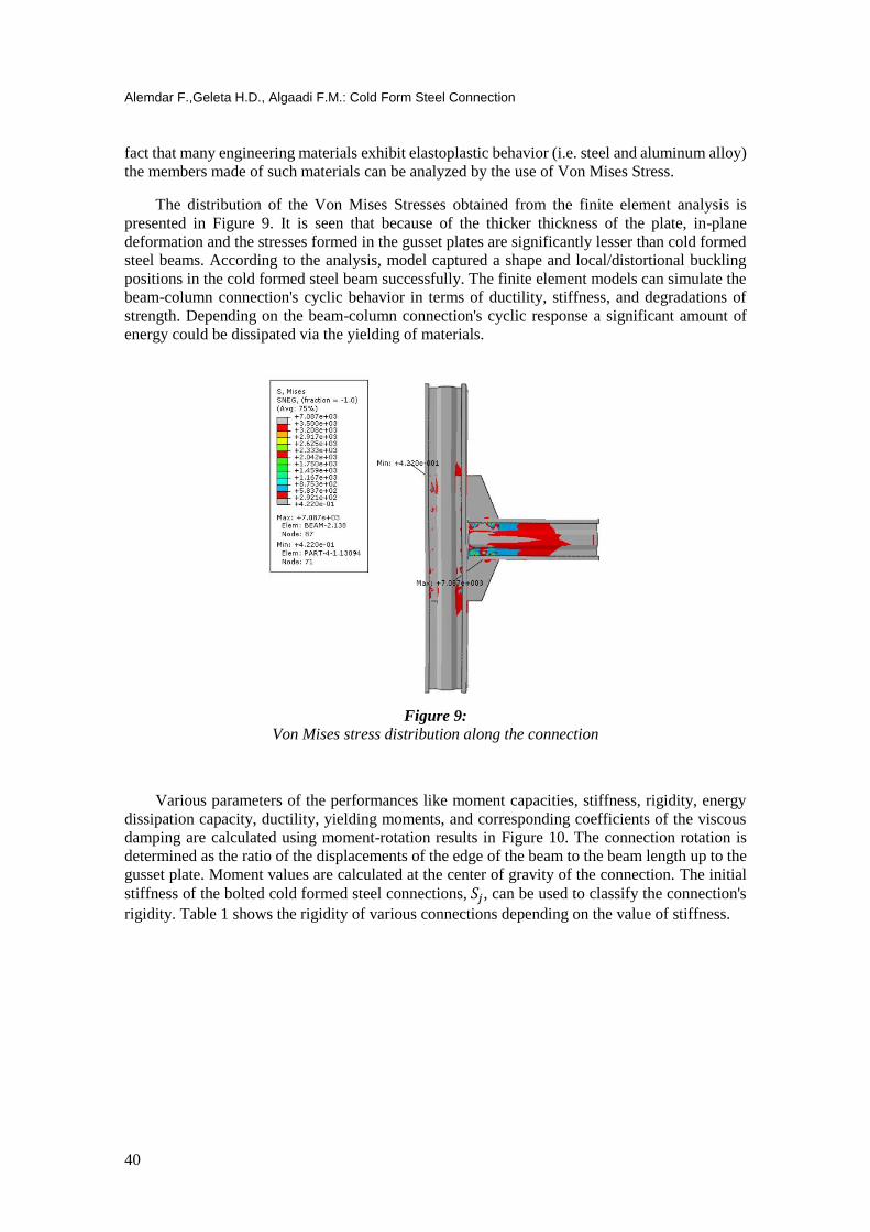
The distribution of the Von Mises Stresses obtained from the finite element analysis is
presented in Figure 9. It is seen that because of the thicker thickness of the plate, in-plane
deformation and the stresses formed in the gusset plates are significantly lesser than cold formed
steel beams. According to the analysis, model captured a shape and local/distortional buckling
positions in the cold formed steel beam successfully. The finite element models can simulate the
beam-column connection's cyclic behavior in terms of ductility, stiffness, and degradations of
strength. Depending on the beam-column connection's cyclic response a significant amount of
energy could be dissipated via the yielding of materials.
Figure 9:
Von Mises stress distribution along the connection
Various parameters of the performances like moment capacities, stiffness, rigidity, energy
dissipation capacity, ductility, yielding moments, and corresponding coefficients of the viscous
damping are calculated using moment-rotation results in Figure 10. The connection rotation is
determined as the ratio of the displacements of the edge of the beam to the beam length up to the
gusset plate. Moment values are calculated at the center of gravity of the connection. The initial
stiffness of the bolted cold formed steel connections, 𝑆𝑗, can be used to classify the connection's
rigidity. Table 1 shows the rigidity of various connections depending on the value of stiffness.

Uludağ University Journal of The Faculty of Engineering, Vol. 26, No. 1, 2021
41
Figure 10:
Moment rotation curve
Depending on the moment-rotation curve above the rigidity and the stiffness of the
connection can be derived and the Secant stiffness can be calculated as;
𝐾𝑠 = 𝑀𝑠
𝜃𝑠 (3)
where 𝑀𝑠 is a moment and 𝜃𝑠 is the rotations under service load.
By using the moment-rotation graph 𝐾𝑠 = 2.91 x 10⁹ is obtained. The next step is
determining the rigidity (𝜆) of the connection which is a ratio of secant stiffness of the connection
to beam flexural rigidity, 𝜆 =𝐾𝑠 (𝐸𝐼 𝐿⁄⁄ ) as described earlier. The length (L) of the beam is 750
mm. The Elastic Modulus and moment of inertia of a beam is 210 GPa and 495.7 x 10⁴ 𝑚𝑚4
respectively. (EI/L) can be calculated as 138.79 x 10⁷ N.mm. Finally, the value of rigidity 𝜆 =2.11, the connection can be classified as semi-rigid connections as defined in Table 1 in the
previous section.
The global moment-rotation behavior of cold formed steel bolted connections is controlled
primarily by the configuration of the bolt distribution, bolt tightening and bearing behavior. The
force-displacement curve can be extracted directly from the result of the model using the loadings
and nodal displacements as shown in Figure 11.
-50
-40
-30
-20
-10
0
10
20
30
40
50
-0,08 -0,06 -0,04 -0,02 0 0,02 0,04 0,06 0,08Mo
men
t(kN
m)
Rotation (Rad)

Alemdar F.,Geleta H.D., Algaadi F.M.: Cold Form Steel Connection
42
Figure11:
Force - displacement curve
If the exact stresses at a point were established, only the criterion of Von Mises could be
used to estimate the first yield load of the material. Von Mises stress distribution of gusset plates
is obtained as shown in Figure 12.
Figure 12:
Von Mises Stress distribution on Gusset Plate
The connections are essential aspects of any building and construction, not just from a point
of view of structural behavior but also in connection to production methods. When any failure
occurs, it is always best that the structural component fails first than connections. In the situation
that the connection fails before the structural member connection fails, then the effects of failure
would become severe. There are the parts of connections that designed to fail first, to confirm that
this happens in a controlled manner if yielding occurs. It is most essential in the semi-rigid
connections since such connections are most probable to stress above yield points and experience
plastic deformation. The design should avoid sudden yielding, as well as sudden failure. The
connection materials, that involve tensioned bolt and weld, are brittle and may be exposed to
sudden failures. Therefore, it should be avoided that the bolt or weld connection in tension to fail.
-80
-60
-40
-20
0
20
40
60
80
-60 -40 -20 0 20 40 60
Fo
rce(
kN
)
Displacement (mm)
Uludağ University Journal of The Faculty of Engineering, Vol. 26, No. 1, 2021
43
In the semi-rigid connection, welded joints are usually avoided, except when they are very
standard and certain (Lee and Foutch, 2000).
There are different types of failure modes that occur in bearing type bolted connections. The
design specification provides minimum spacing and edge distance for bolt connections to avoid
failure of these types. Hancock et al. (2001) suggested that a sheet bearing failures may take place
when the spacing and edge distances are high enough to avoid tear-out failures. Bearing failure
also results in the widening of a hole on the one side of a bolt, but a sheet materials on the other
sides of a bolt are bunched together.
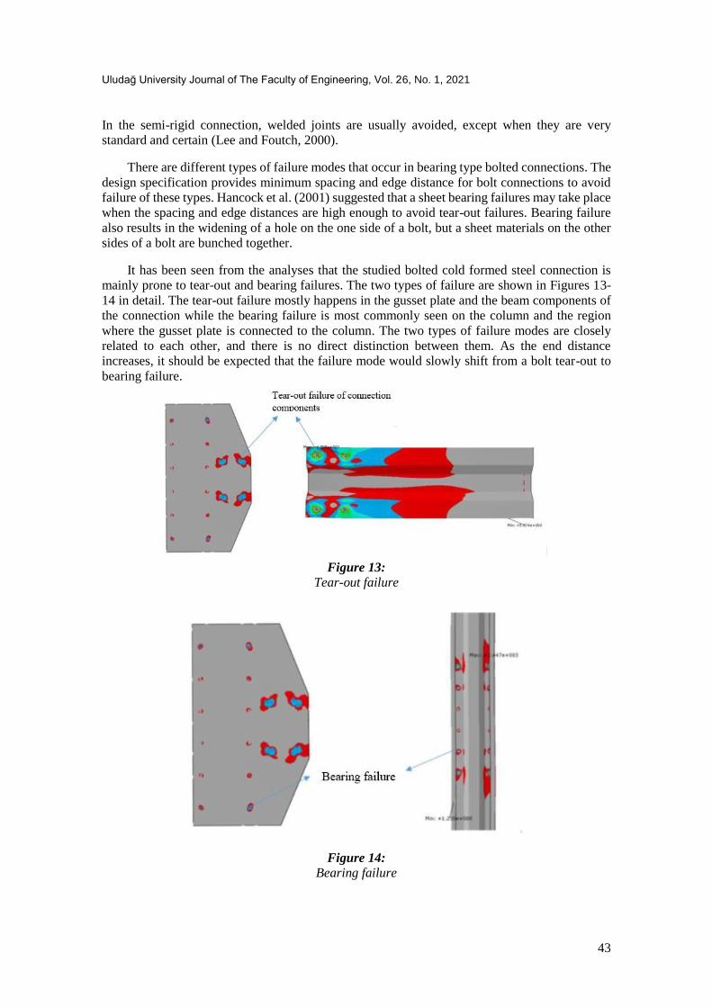
It has been seen from the analyses that the studied bolted cold formed steel connection is
mainly prone to tear-out and bearing failures. The two types of failure are shown in Figures 13-
14 in detail. The tear-out failure mostly happens in the gusset plate and the beam components of
the connection while the bearing failure is most commonly seen on the column and the region
where the gusset plate is connected to the column. The two types of failure modes are closely
related to each other, and there is no direct distinction between them. As the end distance
increases, it should be expected that the failure mode would slowly shift from a bolt tear-out to
bearing failure.
Figure 13:
Tear-out failure
Figure 14:
Bearing failure
Alemdar F.,Geleta H.D., Algaadi F.M.: Cold Form Steel Connection
44
5. SUMMARY AND CONCLUSIONS
Three-dimensional finite element model of a cold formed steel connection under cyclic
loading was generated to investigate the behavior of the bolted connection. Two lipped sigma
sections back-to-back with interconnections are used as beam and column members. The
following conclusions are made according to the finite element analysis results:
The properties of cold formed steel connection has been found as semi-rigid, and a key
factor influencing rigidity is the bearing force near the bolt hole.
The failure modes of the studied connection are shown that the bolted cold formed steel
connection is mainly prone to tear-out and bearing failures. The tear-out failure is seen in
the gusset plate and beam components of the connection whereas the bearing failure is
mostly obtained on the column regions.
Checking gusset plates for the distribution of elastic stress in the expectation is worthless,
since if the plate has flame-cut edges, this has yielded under residual stresses before any
external load application. Although modeling in the past has provided safe designs for
the elastic stress distribution in gusset plates, the existence of residual stresses and design
model inaccuracies make it difficult to predict the actual stress distribution in the gusset
plate. Von Mises failure criterion was used to predict the gusset plate’s first yield load. It
is noted that because of its thicker nature, plane deformations and stress formed in the
gusset plates are significantly lesser than the cold formed steel beams.
In general, the bolted cold-formed steel connections are mostly characterized by semi-rigid
behavior which provides better stability and performance as compared to pin connections and
easier to build as compared to rigid connections. The finite model analysis reveals that modes of
failure of bolted cold formed steel lightweight connection are most commonly the tear-out plate
failure and bearing failure, it is because of the relative thickness of cold formed lightweight steel
connections. As a future research, an experimental study for the analyzed FE model will be done.
CONFLICT OF INTEREST
The author (s) acknowledge that there is no known conflict of interest or common interest
with any institution / organization or person.
AUTHOR CONTRIBUTION
Fatih Alemdar determination of conceptual and / or design processes of the study,
management of conceptual and / or design processes of the study, data collecting, data analysis
and interpretation, creating the manuscript, critical review of intellectual content, final approval
and full liability of the study. Hunde Dechase Geleta management of conceptual and / or design
processes of the study, data collecting, data analysis and interpretation, creating the manuscript,
final approval and full liability of the study. Fuad Mohamed Al-Gaadi management of conceptual
and / or design processes of the study, data collecting, data analysis and interpretation, creating
the manuscript, final approval and full liability of the study.

Uludağ University Journal of The Faculty of Engineering, Vol. 26, No. 1, 2021
45
REFERENCES
1. Bolandim, E. A., Beck A. T. and Malite, M. (2013) Bolted connections in cold-formed steel:
reliability analysis for rupture in net section, Journal of Structural Engineering, 139(5),
748–756. doi: 10.1061/(ASCE)ST.1943-541X.0000566
2. Chen, W. F. (2000) Practical Analysis for Semi-Rigid Frame Design, World Scientific
Publishing Co., River Edge, NJ.
3. Chen, W.F. and Kim, Seung-Eock. (1989) LRFD Steel Design Using Advanced Analysis,
CRC Press, Boca Raton, FL.
4. Dawe, J. L. and Wood, J. V. (2006) Small-scale test behavior of roof trusses cold-formed
steel, Journal of Structural Engineering, 132(4), 608-615. doi: 10.1061/(ASCE)0733-
9445(2006)132:4(608)
5. FEMA-350, (2000). Prestandard and commentary for seismic rehabilitation of buildings,
Federal Emergency Management Agency, Washington, USA.
6. Hancock, G.J., Murray, T. M. and Ellifritt, D.S. (2001) Cold-Formed Steel Structure to the
AISI Specification, Macel Dekker, New York.
7. Hibbitt, Karlsson, and Sorensen. (2015) ABAQUS/standard user's manual. HKS Inc., Dallas,
USA.
8. Lee, K. and Foutch, D. A. SAC/BD-00/25. Performance Prediction and Evaluation of Steel
Special Moment Frames for Seismic Loads, Technical report, SAC Joint Venture, 2000.
9. Kwon, Y. B., Chung, H. S. and Kim, G. D. (2006) Experiments of cold-formed steel
connections and portal frames, Journal of Structural Engineering, 132(4), 600- 607. doi:
10.1061/(ASCE)0733-9445(2006)132:4(600)
10. Liu, J., Xu, L. and Fox, S. (2014) Structural strength of lapped cold-formed steel Z-shaped
purlin connections with vertical slotted holes, 22nd International Specialty Conference On
Cold-Formed Steel Design and Construction, Missouri University of Science and
Technology, St Louis, Missouri.
11. Manson, Leigh. (2006). Analysis and comparison of connections in steel structures, Master
of Engineering Thesis, Massachusetts Institute of Technology, USA.
12. Muhamad, Khiry, B. A. K. (2010). Analysis of cold- formed steel connections, Master of
Engineering Thesis, Universiti Teknologi, Malaysia.
13. Narayanan, R. (1989) Structural Connections: Stability and Strength, Elsevier Science
Publishers, New York.
14. Raftoyiannis, I.G. (2005) The effect of semi-rigid joints and an elastic bracing system on the
buckling load of simple rectangular steel frames, Journal of Constructional Steel Research,
61(9), 1205–1225. doi: 10.1016/j.jcsr.2005.01.005
15. Tan, S. H. (2001) Channel frames with semi-rigid joints, Computers and Structures, 79, 715-
725.
16. Rondal, J. (2000) Cold formed steel members and structures—general report, Journal of
Constructional Steel Research, 55(1–3), 155–158.
17. Davies, J. M. (2000) Recent research advances in cold-formed steel structures, Journal of
Constructional Steel Research, 55(1–3), 267–288.

Alemdar F.,Geleta H.D., Algaadi F.M.: Cold Form Steel Connection
46
18. Gotluru, B. P., Schafer, B. W. and Peköz, T. (2000) Torsion in thin-walled cold-formed steel
beams, Thin Wall Structures, 37(2), 127–145.
19. Put, B. M., Pi, Y. L. and Trahair, N. S. (1999) Bending and torsion of cold-formed channel
beams, Journal of Structural Engineering, 25(5), 540–546.
20. Jo¨nsson, J. (1999) Distortional warping functions and shear distributions in thin-walled
beams, Thin-Walled Structures, 33(4), 245–68.
21. Rogers, C. A. and Hancock, G. J. (1999a) Bolted connection design for sheet steels less than
1.0 mm thick, Journal of Constructional Steel Research, 51(2), 123–146.
22. Rogers, C. A. and Hancock, G. J. (1999b) Screwed connection tests of thin G550 and G300
sheet steels, Journal of Structural Engineering, 125(2), 128–136.
23. Rogers, C. A. and Hancock, G. J. (2000) Failure modes of bolted-sheet-steel connections
loaded in shear, Journal of Structural Engineering, 126(3), 288–296.
24. Ye, J., Hajirasouliha, I., Becque, J. and Pilakoutas, K. (2016) Development of more efficient
cold formed steel channel sections in bending, Thin-Walled Structures, 101, 1-13. doi:
10.1016/j.tws.2015.12.021
25. Rahbari, R., Tyas, A., Davison, J. B. and Stoddart, E. P. (2014) Web shear failure of angle-
cleat connections loaded at high rates, Journal of Constructional Steel Research, 103, 37-48.
doi:10.1016/j.jcsr.2014.07.013
26. Bučmys, Ž. and Daniūnas, A. (2015) Analytical and experimental investigation of cold-
formed steel beam-to-column bolted gusset-plate joints, Journal of Civil Engineering and
Management, 21(8), 1061-1069. doi:10.3846/13923730.2015.1084039
27. Bučmys, Ž. and Daniūnas, A. (2017) Rectangular gusset plate behaviour in cold-formed I-
type steel connections, Journal of Archives of Civil Engineering, 63(2), 3-21. doi:
10.1515/ace-2017-0013
28. Tan, C. S., Lee, Y. H., Lee, Y. L., Mohammad, S., Sulaiman, A., Tahir, M. Md. and Shek, P.
N. (2013) Numerical simulation of cold-formed steel top-seat flange cleat connection, Jurnal
Teknologi, 61(3), 63-71.
29. Yu, C. and Xu, K. (2013) Shear strength of a cold-formed steel sheet in bolted connections
using oversized holes, Journal of Structural Engineering, 139(5), 860–864. doi:
10.1061/(ASCE)ST.1943-541X.0000561
30. Yu, W. W., LaBoube, R. A. and Chen, H. (2020) Cold Formed Steel Design, Wiley, New-
York.
31. EN 1993-1-3, (2006). Eurocode 3: design of steel structures.
part 1.3: general rules – supplementary rules for cold formed members and sheeting,
European Committee for Standardization, Brussels.
32. AISI S100-2007– Appendix 1 (2004). Design of cold-formed steel structural members
using the Direct Strength Method. In: 2004 supplement to the North American
specification for the design of cold-formed steel structures,
United States of America: American Iron and Steel Institute, Washington (DC).


![CLASSIFICATION OF FINITE GROUPS GENERATED BY … · 2015. 9. 24. · CLASSIFICATION OF FINITE REFLECTION-ROTATION GROUPS 3 finite subgroups of SO4 are listed in [10] and the rotation](https://static.fdocuments.us/doc/165x107/5fe7b9a2502c47471f7e39ce/classification-of-finite-groups-generated-by-2015-9-24-classification-of-finite.jpg)


