Experimental characterisation of the moment-rotation ...
9
Engineering Structures 247 (2021) 113132 Available online 16 September 2021 0141-0296/© 2021 The Authors. Published by Elsevier Ltd. This is an open access article under the CC BY license (http://creativecommons.org/licenses/by/4.0/). Experimental characterisation of the moment-rotation behaviour of beam-beam connections using compressed wood connectors Sameer Mehra a , Conan O’Ceallaigh a , Adeayo Sotayo b , Zhongwei Guan b , Annette M. Harte a, * a Timber Engineering Research Group and Ryan Institute, College of Science & Engineering, National University of Ireland Galway, Galway, Ireland b School of Engineering, University of Liverpool, Liverpool, United Kingdom A R T I C L E INFO Keyword: Compressed wood connectors Dowel-type connections Moment-rotation behaviour Beam-beam connections Eurocode 5 Timber-compressed wood connections ABSTRACT The widespread use of energy-intensive metallic connectors and synthetic adhesives in modern timber con- struction has negative implications for the end-of-life disposal or re-use of the structural timber components. Therefore, it is favourable to substitute metallic connectors and synthetic adhesives with bio-based alternatives such as wood-based connectors. Recent studies have shown that densified or compressed wood (CW) with su- perior mechanical properties could be suitable for the manufacture of wood-based connectors in the form of CW dowels and CW plates. This study experimentally examines the moment-rotation behaviour of semi-rigid type timber-CW beam-beam connections under pure bending. The study also assesses the suitability of current design rules to predict the moment capacity of timber-CW connections. The comparative study has shown that the moment capacity of the timber-CW connection can be conservatively predicted from the characteristic load- carrying capacity of the connections calculated using the EC 5 strength equations. 1. Introduction Connections in timber buildings are generally classified as tradi- tional timber connections, metallic connections or glued connections [1]. Traditional timber connections, such as mortise-tenon and scarf joints, are widely used in older timber buildings around the world [2–5]. However, in more recent years, the use of traditional joinery techniques has been curtailed in favour of quicker, efficient and more economic connection designs using mechanical connectors [6–11]. Timber con- nections using metallic dowel-type connectors are commonly used in contemporary heavy timber structures due to their higher load-carrying capacity and ductile behaviour [12–15]. However, the use of metallic connectors in timber connections often leads to stress concentrations in the connection members due to the large difference between the stiffness of the connectors and timber [16–18]. Another commonly used timber connection technique involves the use of synthetic adhesives with or without mechanical connectors [19–22]. A high connection efficiency can be achieved using synthetic adhesives, but they compromise the sustainability credentials of using timber [23–26] and therefore, it is favourable to replace metallic connectors and synthetic adhesives with a more sustainable solution. In recent years, the densification of wood by compression has been the subject of several research programmes due to its high potential to improve the mechanical properties of timber [26–30]. Densified or compressed wood (CW) can be produced using chemical or mechanical treatments or a combination of these treatments such as thermo-hydro- mechanical, thermo-mechanical, viscoelastic thermal compression and oil heated treatment [31–40]. The densification of wood has been shown to improve the density, material strength, stiffness and hardness of timber [41] and CW in the form of dowels offers high strength and stiffness compared to traditional hardwood dowels and could be used in heavy timber connections [42–47]. To investigate the structural feasi- bility of CW connectors in heavy timber connections, Jung et al. [45,46] developed column-sill and beam-column connections using CW dowels and CW plates as an alternative to steel connectors. The results demonstrated that good structural performance of the connections can be achieved due to the high shear performance CW dowels and superior bending and embedment properties of CW plates. However, there was no comparison of the structural performance to commonly used timber- steel type connections. Mehra et al. [48] investigated the structural performance of CW connectors within a flitch plate type moment connection and compared this to equivalent slotted-in steel plate con- nections which are commonly used in timber connections. It was shown that the CW-timber connection system achieved a mean failure load of * Corresponding author. E-mail address: [email protected] (A.M. Harte). Contents lists available at ScienceDirect Engineering Structures journal homepage: www.elsevier.com/locate/engstruct https://doi.org/10.1016/j.engstruct.2021.113132 Received 22 April 2021; Received in revised form 30 July 2021; Accepted 1 September 2021
Transcript of Experimental characterisation of the moment-rotation ...

Engineering Structures 247 (2021) 113132
Available online 16 September 20210141-0296/© 2021 The Authors. Published by Elsevier Ltd. This is an open access article under the CC BY license (http://creativecommons.org/licenses/by/4.0/).
Experimental characterisation of the moment-rotation behaviour of beam-beam connections using compressed wood connectors
Sameer Mehra a, Conan O’Ceallaigh a, Adeayo Sotayo b, Zhongwei Guan b, Annette M. Harte a,*
a Timber Engineering Research Group and Ryan Institute, College of Science & Engineering, National University of Ireland Galway, Galway, Ireland b School of Engineering, University of Liverpool, Liverpool, United Kingdom
A R T I C L E I N F O
Keyword: Compressed wood connectors Dowel-type connections Moment-rotation behaviour Beam-beam connections Eurocode 5 Timber-compressed wood connections
A B S T R A C T
The widespread use of energy-intensive metallic connectors and synthetic adhesives in modern timber con-struction has negative implications for the end-of-life disposal or re-use of the structural timber components. Therefore, it is favourable to substitute metallic connectors and synthetic adhesives with bio-based alternatives such as wood-based connectors. Recent studies have shown that densified or compressed wood (CW) with su-perior mechanical properties could be suitable for the manufacture of wood-based connectors in the form of CW dowels and CW plates. This study experimentally examines the moment-rotation behaviour of semi-rigid type timber-CW beam-beam connections under pure bending. The study also assesses the suitability of current design rules to predict the moment capacity of timber-CW connections. The comparative study has shown that the moment capacity of the timber-CW connection can be conservatively predicted from the characteristic load- carrying capacity of the connections calculated using the EC 5 strength equations.
1. Introduction
Connections in timber buildings are generally classified as tradi-tional timber connections, metallic connections or glued connections [1]. Traditional timber connections, such as mortise-tenon and scarf joints, are widely used in older timber buildings around the world [2–5]. However, in more recent years, the use of traditional joinery techniques has been curtailed in favour of quicker, efficient and more economic connection designs using mechanical connectors [6–11]. Timber con-nections using metallic dowel-type connectors are commonly used in contemporary heavy timber structures due to their higher load-carrying capacity and ductile behaviour [12–15]. However, the use of metallic connectors in timber connections often leads to stress concentrations in the connection members due to the large difference between the stiffness of the connectors and timber [16–18]. Another commonly used timber connection technique involves the use of synthetic adhesives with or without mechanical connectors [19–22]. A high connection efficiency can be achieved using synthetic adhesives, but they compromise the sustainability credentials of using timber [23–26] and therefore, it is favourable to replace metallic connectors and synthetic adhesives with a more sustainable solution.
In recent years, the densification of wood by compression has been
the subject of several research programmes due to its high potential to improve the mechanical properties of timber [26–30]. Densified or compressed wood (CW) can be produced using chemical or mechanical treatments or a combination of these treatments such as thermo-hydro- mechanical, thermo-mechanical, viscoelastic thermal compression and oil heated treatment [31–40]. The densification of wood has been shown to improve the density, material strength, stiffness and hardness of timber [41] and CW in the form of dowels offers high strength and stiffness compared to traditional hardwood dowels and could be used in heavy timber connections [42–47]. To investigate the structural feasi-bility of CW connectors in heavy timber connections, Jung et al. [45,46] developed column-sill and beam-column connections using CW dowels and CW plates as an alternative to steel connectors. The results demonstrated that good structural performance of the connections can be achieved due to the high shear performance CW dowels and superior bending and embedment properties of CW plates. However, there was no comparison of the structural performance to commonly used timber- steel type connections. Mehra et al. [48] investigated the structural performance of CW connectors within a flitch plate type moment connection and compared this to equivalent slotted-in steel plate con-nections which are commonly used in timber connections. It was shown that the CW-timber connection system achieved a mean failure load of
* Corresponding author. E-mail address: [email protected] (A.M. Harte).
Contents lists available at ScienceDirect
Engineering Structures
journal homepage: www.elsevier.com/locate/engstruct
https://doi.org/10.1016/j.engstruct.2021.113132 Received 22 April 2021; Received in revised form 30 July 2021; Accepted 1 September 2021
Engineering Structures 247 (2021) 113132
2
about 80% of that achieved for an equivalent steel-timber connection system. However, these findings are based on the limited number of test configurations and smaller sample size, hence, further tests are required. Further, literature review showed limited information on the moment- capacity of timber-CW connection under pure bending.
This study aims to experimentally characterise the moment-rotation behaviour of semi-rigid type beam-beam timber moment connections using CW dowels and CW plates as a potential alternative to steel con-nectors within the beam-beam connection system. The connection specimens in this study are produced using a varying number of CW dowels and two different CW plate thicknesses. A connection comprising 6 dowels on either side of the connected members can be seen in Fig. 1. This paper describes the connection design, manufacturing and assem-bly process, the experimental testing and the test results for the devel-oped connection systems. Finally, the experimental test results are compared with design values calculated based on the Eurocode 5 (EC 5) [49] guidelines and other relevant research studies [1,50] to assess their suitability for the design of timber-CW connections.
2. Materials
This section presents information on the materials used to manu-facture the glued laminated beams and the CW material used in this study to produce the all-wood beam-beam connections.
2.1. Beams
The structural members used in this study were manufactured using kiln-dried timber boards of Irish-grown Douglas fir (Pseudotsuga men-ziesii) [51]. A total of twenty glued-laminated beams were manufactured using four laminates with a length of 1580 mm, a width of 130 mm and a thickness of 40 mm. The laminates were glued together using a one- component PU adhesive and clamped in a rig to a minimum pressure of 0.6 MPa in accordance with EN 14080 [52] to produce a final glued laminated cross-section with a width of 130 mm and a depth of 160 mm. Material characterisation tests were also carried out to determine the density and embedment strength of this species. It was found that the mean density of the glued laminated material, based on clear specimens at 12% moisture content, was 570 kg/m3. The embedment strength of the timber, determined experimentally in accordance with EN 383 [53] in the parallel (fh,1,0) and perpendicular (fh,1,90) to the grain directions, were found to be 37 MPa (n = 20, COV = 15.2%) and 22 MPa (n = 20, COV = 26.4%), respectively. The characteristic values of the embedment strength were calculated as per EN 14358 [54]. All the glued-laminated specimens were conditioned at a temperature of 20 ± 2 ◦C and relative humidity of 65 ± 5% prior to connection assembly and testing.
2.2. Compressed wood (CW) connectors
To manufacture the CW dowels, visually graded uncompressed Scots
pine (Pinus sylvestris) was radially compressed to a compression ratio (CR) of 54%. The CR refers to the difference between the initial and final thickness of the wood as a percentage of the initial thickness. The timber was radially compressed using a process known as thermo-mechanical densification which resulted in a mean oven-dry density of 1285 kg/ m3. This process was carried out at the University of Liverpool and a detailed description of the densification process was previously dis-cussed by Sotayo et al. [26]. All the CW dowels used in this study were 10 ± 0.3 mm in diameter. The CW plate material was 68% radially compressed Western hemlock (Tsuga heterophylla). The plate manufacturing process was the same as that of the CW dowels except for the different compression ratio (CR) and geometry. This study utilises two different plate thicknesses of 10 mm and 20 mm whereas the length (l = 500 mm) and width (w = 60 mm) were constant. The mean density of the CW plates was 1300 kg/m3.
Similar to the glued-laminated specimens, the characteristic embedment strength of the CW plates in the parallel (fh,2,0) and the perpendicular (fh,2,90) to the grain directions were also determined experimentally in accordance with the guidelines of EN 383 [53]. It was found that the characteristic embedment strength of the CW (fh,2,0,k) parallel to the grain and (fh,2,90,k) perpendicular to the grain are 189 MPa (n = 5 and COV = 5.9%) and 142 MPa (n = 5 and COV = 14.2%), respectively.
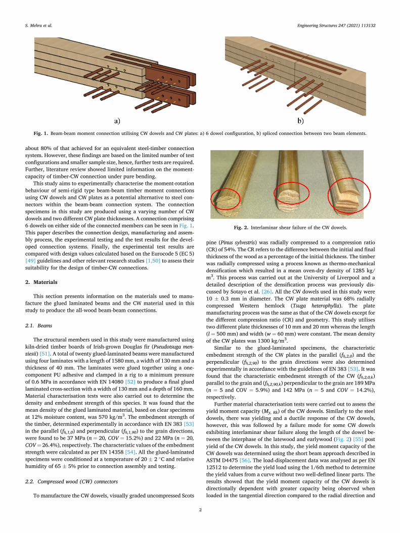
Further material characterisation tests were carried out to assess the yield moment capacity (My, Rk) of the CW dowels. Similarly to the steel dowels, there was yielding and a ductile response of the CW dowels, however, this was followed by a failure mode for some CW dowels exhibiting interlaminar shear failure along the length of the dowel be-tween the interphase of the latewood and earlywood (Fig. 2) [55] post yield of the CW dowels. In this study, the yield moment capacity of the CW dowels was determined using the short beam approach described in ASTM D4475 [56]. The load-displacement data was analysed as per EN 12512 to determine the yield load using the 1/6th method to determine the yield values from a curve without two well-defined linear parts. The results showed that the yield moment capacity of the CW dowels is directionally dependent with greater capacity being observed when loaded in the tangential direction compared to the radial direction and
Fig. 1. Beam-beam moment connection utilising CW dowels and CW plates: a) 6 dowel configuration, b) spliced connection between two beam elements.
Fig. 2. Interlaminar shear failure of the CW dowels.
S. Mehra et al.

Engineering Structures 247 (2021) 113132
3
at an angle of 45◦. However, as the insertion of dowels in a specific orientation on-site is not always practical, this study utilises the char-acteristic yield moment capacity of the CW dowels (My,Rk, CW) of 3972 Nmm (n = 15 and COV = 27.5%) determined from the results of all specimens tested regardless of orientation.
The yield moment capacity of the CW dowels (My,Rk,CW) was deter-mined using the following expression [57].
My,Rk,CW =38⋅Fy⋅d (1)
where Fy is the yield load, determined as the intersection between the secant and tangent line on two sections of the load-deformation curve and d is the diameter of the CW dowel. In addition to interlaminar shear failure, some connection specimens exhibited cross-grain shear failure of the CW dowels as reported by Mehra et al. [48,58]. Therefore, the cross- grain shear strength of CW dowels was also experimentally tested and considered for the design calculations in this study. The characteristic cross-grain shear strength of CW dowels (fsp,k) was determined from the experimental results of 10 specimens (five tested in the radial and tangential directions). The characteristic value of cross grain shear strength was found to be 50.8 N/mm2 (n = 5 and COV = 10.4%) calculated in accordance with EN 14358 [54].
3. Connection configuration, assembly and test procedure
3.1. Connection configuration
The configuration of the beam-beam connections with CW plates and CW dowels can be seen in Fig. 3. Vertically oriented grooves were routed at the end of each beam starting from the top/bottom surface to a depth of 60 mm to house the CW plates. Each connection design comprised four slotted-in compressed wood plates, two in the compression zone and two in the tension zone of the beams. Two dowel arrangements were examined in this study, namely, the 6-dowel arrangement and the 8- dowel arrangement. For the 6-dowel arrangement shown in Fig. 3a, six dowels were used to connect the CW plates to each beam (3 top and 3 bottom; 12 dowels in total). There was a total of five connections of the 6-dowel arrangement that comprised two specimens using 10 mm thick CW plates and three specimens using 20 mm thick CW plates. For the 8- dowel arrangement shown in Fig. 3b, eight dowels with reduced spacing were used to connect the CW plates to each beam (4 top and 4 bottom; 16 dowels in total). The dowel spacing implemented in this study was governed by current spacing rules for steel dowel spacing in EC5. There was a total of five connections of the 8-dowel arrangement that comprised two specimens using 10 mm thick CW plates and three specimens using 20 mm thick CW plates. The cross-section of each connection type is given in Fig. 4.
Fig. 3. 3D design configuration and edge/end spacing connections with (a) 6-dowel arrangement, and (b) 8-dowel arrangement (all dimensions in mm).
Fig. 4. Cross-section of the connection using, (a) 10 mm thick CW plates, and (b) 20 mm thick CW plates (all dimensions in mm).
S. Mehra et al.

Engineering Structures 247 (2021) 113132
4
Table 1 summarises the number of replications, plate thickness, number of dowels and labelling system for each connection type. The series naming convention indicates the connection type, dowel arrangement and CW plate thickness. Therefore, the beam-beam (BB) connection type with a 6-dowel arrangement and 10 mm thick CW plates is labelled BB-6-10. The final digit indicates the repetition number of the specimen within the series.
3.2. Assembly of the connections
During the assembly process, each beam was fixed in position using a steel clamp while the CW plates were inserted in pre-routed slots. Once aligned, the holes for the dowels were predrilled using a pillar drill, followed by the insertion of the dowels. For the selection of appropriate drilling bits, it was found that a 10.2 mm hole diameter is appropriate for dowels of 10 mm − 10.3 mm diameter. Also, to facilitate easy insertion of the CW dowels, the leading end of the dowels was chamfered to a conical shape. After fabrication was completed, the spliced con-nections were conditioned for thirty days at a relative humidity of 65 ±5% and a temperature of 20 ± 2 ◦C in accordance with EN 408 [59] prior to testing.
3.3. Test procedure
All beam-beam connections were tested in flexure over a simply supported span using a four-point bending test set up as seen in Fig. 5 in accordance with EN 408 [59]. The connection was located at mid-span in the shear-free zone. This ensures that the connection was subjected to pure bending. Lateral supports were placed at the end of the beams to avoid lateral movement during the test.
Monotonic loading tests were carried out using a Dartec 500 kN Servo hydraulic testing machine under displacement control loading at a rate of 6.8 mm/min. The vertical displacement at mid-span of the connection was measured using a micro-epsilon optoNCDT1420 laser with an accuracy of 8 µm. There were four linear variable differential transformers (LVDTs), which were used to measure the rotational angle
of the connection. As shown in Fig. 5, pairs of LVDTs were placed symmetrically on the right side (LVDT Δ1 and Δ2) and left side (LVDT Δ3 and Δ4) of the connection with a fixed spacing of 300 mm between each pair. The rotational angle (θ) of each side was determined from the relative movement of the LVDTs divided by the spacing.
Each connection was initially preloaded up to 40% of the maximum load and unloaded to 10% in accordance with EN 26891 [60]. Each connection was then loaded to failure and the test was terminated when the load reduced to 50% of the maximum load. The experimental moment capacity (Mexp) of the connection was calculated using the following expression:
Mexp =Fmax
2× r (2)
where Fmax is the maximum load and r is the lever arm distance (960 mm).
Each beam-beam connection arrangement is comprised of two separate and similar connections connected in series. So, the experi-mental rotational stiffness of the connection (kexp) was calculated using the following equations [50]:
kexp =1
(1
kexp,1+ 1
kexp,2
) (3)
where kexp,1 and kexp,2 are the rotational stiffnesses of each side of the connection calculated using Eq. (4).
kexp,i =Mexp,i,40 − Mexp,i,10
θexp,i,40 − θexp,i,10(4)
where Mexp,i,10 is 10% of the moment capacity (Mexp), Mexp,i,40 is 40% of the Mexp, and θexp,i,10 and θexp,i,40 are the corresponding rotational angles of the ith connection.
The ductility ratio (D) was calculated as per EN 12512 [61] using the following expression:
D =Vu
Vy(5)
where Vu is the ultimate midspan displacement taken at a load level of 80% of Fmax, and Vy is the yield midspan displacement, which was calculated based on the 1/6 method [61].
4. Results and discussion
4.1. Moment-rotation behaviour
The moment-rotation behaviour of the tested connections can be seen in Fig. 6. It should be noted that the pre-loading procedure to 40% of the maximum load has been removed for clarity. When examining the moment-rotation behaviour of the different connection configurations,
Table 1 Beam-beam test program summary.
Connection type Number of replications
CW plate thickness (mm)
Total number of dowels
Label
BB-6-10 series 2 10 12 BB-6-10-1 BB-6-10-2
BB-6-20 series 3 20 12 BB-6-20-1 BB-6-20-2 BB-6-20-3
BB-8-10 series 2 10 16 BB-8-10-1 BB-8-10-2
BB-8-20 series 3 20 16 BB-8-20-1 BB-8-20-2 BB-8-20-3
Fig. 5. Configuration of the test set up for four-point bending as per EN 408 [59] (all dimensions in mm).
S. Mehra et al.

Engineering Structures 247 (2021) 113132
5
it was clear that the majority of the test specimens failed in a brittle manner. Both the 6-dowel and 8-dowel arrangements using 10 mm CW thick plates showed a brittle failure due to splitting in the CW plates along the row of the dowels. A similar result was also observed for the 8- dowel arrangements using 20 mm CW thick plates. The connection design using the 6-dowel arrangement and 20 mm thick CW plates, shown in Fig. 6a showed greater energy dissipation and ductility when compared to the other connection designs. The increased ductility was not a direct result of the increased CW plate thickness as such increases
were not observed in the 8-dowel configuration with a similar plate thickness. The increase in ductility is a combination of increased CW plate thickness and increased spacing between the CW dowels. In contrast, the 8-dowel arrangement using the 20 mm thick CW plates demonstrated a brittle failure mode but had a lower inter-dowel spacing and end distances. In the 6-dowel arrangement with 20 mm thick CW plates, greater spacing resulted in greater deformation of the CW dowels and embedment of the surrounding timber and delayed the brittle splitting of the CW plates that was observed in the other arrangements.
Table 2 summarises the experimental test results for all connections examined. The connection design using the 8-dowel arrangement with 20 mm thick CW plates has shown to result in the highest mean moment capacity, which is approximately 39% higher than the lowest value that was observed for the 6-dowel arrangement using 20 mm thick CW plates. However, the 6-dowel arrangement using the 20 mm CW thick plates had the highest mean rotational stiffness, which is approximately 27% higher than the lowest value that was observed for the 6-dowel arrangement using 10 mm thick CW plates. The connection design using the 6-dowel arrangement with 20 mm thick CW plates had the highest mean ductility ratio, which is approximately 140% higher than the lowest value that was observed for the 8-dowel arrangement using 10 mm thick CW plates. The results indicate that a greater number of dowels and an increase in the thickness of the CW plate increases the mean moment carrying capacity but also the potential for brittle failure. It was also observed that increasing the spacing and end distances can improve the ductility of the connection.
4.2. Failure modes
To further examine the experimental results, the failure modes of the different arrangements are presented. All the specimens using 10 mm
Fig. 6. Moment-rotation behaviour of all connection types, (a) 6-dowel arrangement using 10 mm and 20 mm CW plates and, (b) 8-dowel arrangement using 10 mm and 20 mm CW plates.
Table 2 Moment capacity, rotational stiffness and ductility ratio of tested specimens.
Specimen label
Moment capacity (kN.m)
Rotational stiffness (kN. m/rad)
Ductility ratio
BB-6-10-1 5.7 115.0 1.3 BB-6-10-2 8.1 170.7 1.4 Mean 6.9 142.9 1.4 COV 25.1% 27.5% 2.7% BB-6-20-1 7.0 224.3 2.4 BB-6-20-2 5.9 168.2 2.5 BB-6-20-3 6.4 197.0 2.2 Mean 6.4 196.5 2.4 COV 8.5% 14.3% 7.5% BB-8-10-1 5.8 195.1 0.9 BB-8-10-2 7.2 177.6 1.1 Mean 6.5 186.4 1.0 COV 14.8% 6.6% 9.4% BB-8-20-1 7.5 148.9 1.1 BB-8-20-2 10.2 160.3 1.4 BB-8-20-3 9.1 192.9 1.2 Mean 8.9 167.4 1.2 COV 14.8% 13.7% 14.8%
Fig. 7. BB-6-10 connections – splitting of CW plates along the row of dowels.
S. Mehra et al.

Engineering Structures 247 (2021) 113132
6
CW plates resulted in failure due to splitting of the CW plates along the row of dowels in the tension zone. An example of this can be seen in the BB-6-10 arrangement in Fig. 7. Due to the brittle failure of the CW plates in the tension zone, a sudden decline in the moment capacity was observed without any further increase. A similar brittle failure mode was observed for the 8-dowel arrangement with 20 mm thick CW plates; however, increasing the CW plate thickness meant it did not split and, instead, splitting was observed in the glued laminated timber along the row of CW dowels in the tension zone.
In the 6-dowel arrangement with 20 mm thick CW plates, initial failure was observed in the CW plates in the tension zone due to splitting along the row of dowels. This resulted in a reduction in moment capacity of 8%-20%; however, the load recovered until interlaminar and/or cross-grain shear failure occurred within the CW dowels as shown in Fig. 8a and b. There was also evidence that partial plastic hinges were
formed in the CW dowels as shown in Fig. 8b. Similar ductile behaviour was observed on experimental tests on individual fasteners. Once the moment capacity was attained, splitting of the glued-laminated timber was observed along the row of CW dowels in the tension zone and later in the compression zone as shown in Fig. 8c.
These results indicate that inter-dowel spacing, and end distance greatly influence the failure behaviour of such connections and, by extension, the moment capacity and ductility. The optimal dowel spacing, and end distances need to be further investigated to determine the full potential of this innovative and sustainable connection solution.
Fig. 8. BB-6-20 connections, (a) interlaminar shear failure of CW dowels, (b) ductile behaviour indicated by the formation of plastic hinges and cross-grain shear failure of the CW dowels and, (c) splitting failure in the timber and CW plates.
S. Mehra et al.
Engineering Structures 247 (2021) 113132
7
5. Design calculations
5.1. Design calculation procedure
The use of CW connectors is relatively new and there are no stan-dards that provide guidance for designing timber-CW connections. Therefore, it is desirable to first evaluate the suitability of existing standards for designing and predicting the mechanical characteristics of dowel-type connections. Eurocode 5 (EC 5) [49], which is a widely accepted standard for designing steel-timber or timber-timber dowel- type connections, provides guidelines for the calculation of the load- carrying capacity of laterally loaded connections fastened using metal dowel-type fasteners in addition to providing limits on dowel spacing and edge distances, which when followed, ensure that brittle failure mechanism such as row shear does not occur. The considered failure modes in EC 5 are limited to embedment failure of the connected members, yielding of the dowels and combinations thereof.
In this study, the calculation of the moment capacity of timber-CW connections based on EC5 was supplemented with the guidelines given by Porteous and Kermani [50] and Blaß and Sandhaas [1]. The characteristic load-carrying capacity of laterally loaded double shear timber-timber connections fastened using metal dowels can be calcu-lated based on the failure modes shown in Fig. 9 and their corresponding strength equations in Table 3.
The characteristic load-carrying capacity per shear plane per fastener is the minimum value obtained from the EC 5 equations shown in Table 3.
where Fv,Rk is the characteristic load-carrying capacity of per dowel per shear plane, t1 is the thickness of the side member, t2 is the thickness of the central member, d is the diameter of the dowel, fh,1,k is the characteristic embedment strength of the side member, fh,2,k is the characteristic embedment strength of the central member, My,Rk is the yield moment of the fastener, Fax,Rk is the axial withdrawal capacity of the fastener, and β is the ratio between the embedment strength of connected members. The axial withdrawal capacity (Fax,Rk) of the fastener and its contribution to the lateral load-carrying capacity, which is termed the rope effect, is assumed to be zero for steel dowels and is adhered to in this case with timber dowels.
Additionally, in the current study, it is important to consider that CW
dowels exhibit cross-grain shear failure. The characteristic load-carrying capacity per dowel per shear plane can be calculated using the following expression as recommended by Schmidt et al. [62] and Sandberg et al. [63].
Fv,Rk =πd2
4fsp,k (6)
where fsp,k is the characteristic cross-grain shear strength of the CW dowels and d is the diameter of the dowel. This failure mode was not found to be governing under the connections examined in this study.
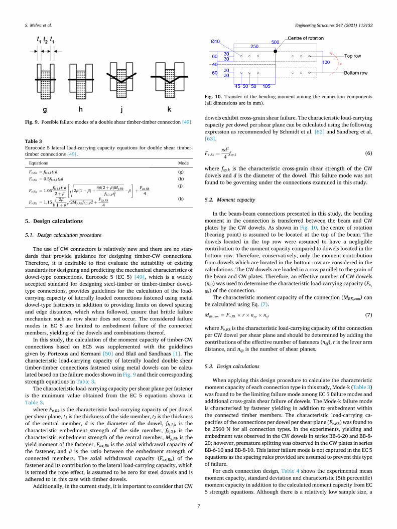
5.2. Moment capacity
In the beam-beam connections presented in this study, the bending moment in the connection is transferred between the beam and CW plates by the CW dowels. As shown in Fig. 10, the centre of rotation (bearing point) is assumed to be located at the top of the beam. The dowels located in the top row were assumed to have a negligible contribution to the moment capacity compared to dowels located in the bottom row. Therefore, conservatively, only the moment contribution from dowels which are located in the bottom row are considered in the calculations. The CW dowels are loaded in a row parallel to the grain of the beam and CW plates. Therefore, an effective number of CW dowels (nef) was used to determine the characteristic load-carrying capacity (Fv,
Rk) of the connection. The characteristic moment capacity of the connection (MRK,con) can
be calculated using Eq. (7).
MRk,con = Fv,Rk × r × nsp × nef (7)
where Fv,Rk is the characteristic load-carrying capacity of the connection per CW dowel per shear plane and should be determined by adding the contributions of the effective number of fasteners (nef), r is the lever arm distance, and nsp is the number of shear planes.
5.3. Design calculations
When applying this design procedure to calculate the characteristic moment capacity of each connection type in this study, Mode-k (Table 3) was found to be the limiting failure mode among EC 5 failure modes and additional cross-grain shear failure of dowels. The Mode-k failure mode is characterised by fastener yielding in addition to embedment within the connected timber members. The characteristic load-carrying ca-pacities of the connections per dowel per shear plane (Fv,Rk) was found to be 2560 N for all connection types. In the experiments, yielding and embedment was observed in the CW dowels in series BB-6-20 and BB-8- 20; however, premature splitting was observed in the CW plates in series BB-6-10 and BB-8-10. This latter failure mode is not captured in the EC 5 equations as the spacing rules provided are assumed to prevent this type of failure.
For each connection design, Table 4 shows the experimental mean moment capacity, standard deviation and characteristic (5th percentile) moment capacity in addition to the calculated moment capacity from EC 5 strength equations. Although there is a relatively low sample size, a
Fig. 9. Possible failure modes of a double shear timber-timber connection [49].
Table 3 Eurocode 5 lateral load-carrying capacity equations for double shear timber- timber connections [49].
Equations Mode
Fv,Rk = fh,1,kt1d (g) Fv,Rk = 0.5fh,2,kt2d (h)
Fv,Rk = 1.05fh,1,kt1d2 + β
[
2β(1 + β) +4β(2 + β)My,Rk
fh,1,kt21
√
− β
]
+Fax,Rk
4
(j)
Fv,Rk = 1.15
2β1 + β
√2My,Rkfh,1,kd
√+
Fax,Rk
4 (k)
Fig. 10. Transfer of the bending moment among the connection components (all dimensions are in mm).
S. Mehra et al.

Engineering Structures 247 (2021) 113132
8
characteristic value has been calculated using the experimentally determined standard deviation and the results have shown that the calculated moment capacity, in accordance with the EC 5 method, is conservative. This indicates that EC 5 strength equations may be used to predict the moment capacity of timber-CW connections but it is noted that these findings are based on the limited number of specimens of each connection type.
6. Summary and conclusions
In this study, the moment-rotation behaviour of all-wood timber-CW connection systems utilising CW connectors under pure bending has been evaluated experimentally. Four different connection designs were developed using a varying number of CW dowels, and varying CW plate thicknesses. The effect of these parameters on the structural perfor-mance of the connections is presented. Also, experimental results were compared with the design calculations carried out based on the Euro-code 5 (EC 5) [49] guidelines and other relevant research studies [1,50]. Based on the number of specimens tested in the current study, the following conclusions can be drawn:
• The experimental test results have shown that greater moment car-rying capacity can be achieved by increasing the number of CW dowels and the thickness of the CW plates in the connection.
• The ductility of the connection was mainly affected by the spacing of the dowels and the thickness of the CW plates. A more ductile response was shown to be achieved through a combination of larger dowel spacing and thicker CW plates.
• The experimental results did not show any clear relationship be-tween the rotational stiffness and other connection parameters such as the number of CW dowels and the thickness of CW plates.
• The design calculations for the moment capacities of all experi-mentally tested connection designs were shown to be safe when determined using load-carrying capacity values based on the EC 5 strength equations.
Finally, the study concludes that CW connectors have marked po-tential as an alternative to high embodied energy steel connectors and synthetic adhesives in the timber construction industry. The developed timber-CW connection system can be disposed of/recycled at the end of the building’s life cycle further improving the environmental credentials of the system and reducing the impact on the environment. Further-more, the idea of using wood-based connectors fits well with the ongoing transition towards a bio-based and circular economy.
CRediT authorship contribution statement
Sameer Mehra: Writing – original draft, Investigation, Visualiza-tion, Formal analysis, Validation. Conan O’Ceallaigh: Conceptualiza-tion, Methodology, Formal analysis, Supervision, Writing – review & editing. Adeayo Sotayo: Resources. Zhongwei Guan: Funding acqui-sition, Resources. Annette M. Harte: Conceptualization, Methodology, Supervision, Writing – review & editing, Funding acquisition.
Declaration of Competing Interest
The authors declare that they have no known competing financial
interests or personal relationships that could have appeared to influence the work reported in this paper.
Acknowledgements
The study was conducted within the framework of the project “To-wards Adhesive Free Timber Buildings - AFTB” at the College of Science and Engineering, National University of Ireland Galway, Ireland. The AFTB project is funded by the European Regional Development Fund (ERDF) via Interreg North-West Europe grant 348. The contribution of the technical staff of the College of Science and Engineering, NUI Gal-way, in particular, Peter Fahy and Colm Walsh is gratefully acknowledged.
References
[1] Blaß HJ, Sandhaas C. Timber Engineering - Principles for Design. KIT Scientific Publishing, Karlsruhe, Germany; 2017. doi:10.5445/KSP/1000069616.
[2] Shanks J, Walker P. Strength and Stiffness of All-Timber Pegged Connections. J Mater Civ Eng 2009;21(1):10–8.
[3] Arciszewska-Kedzior A, Kunecký J, Hasníkova H, Sebera V. Lapped scarf joint with inclined faces and wooden dowels: Experimental and numerical analysis. Eng Struct 2015;94:1–8. https://doi.org/10.1016/j.engstruct.2015.03.036.
[4] Kunecký J, Hasníkova H, Kloiber M, Milch J, Sebera V, Tippner J. Structural assessment of a lapped scarf joint applied to historical timber constructions in central Europe. Int J Archit Herit 2018;12(4):666–82. https://doi.org/10.1080/ 15583058.2018.1442524.
[5] Moradei J, Brütting J, Fivet C, Sherrow-Groves N, Wilson D, Fischer A, et al. Structural Characterization of Traditional Moment-Resisting Timber Joinery. Proc. IASS Symp. 2018, Creat. Struct. Des., Boston, USA; 2018.
[6] Ringhofer A, Brandner R, Blaß HJ. Cross laminated timber (CLT): Design approaches for dowel-type fasteners and connections. Eng Struct 2018;171: 849–61. https://doi.org/10.1016/j.engstruct.2018.05.032.
[7] Hossain A, Popovski M, Tannert T. Cross-laminated timber connections assembled with a combination of screws in withdrawal and screws in shear. Eng Struct 2018; 168:1–11. https://doi.org/10.1016/j.engstruct.2018.04.052.
[8] Gecys T, Daniunas A, Bader TK, Wagner L, Eberhardsteiner J. 3D finite element analysis and experimental investigations of a new type of timber beam-to-beam connection. Eng Struct 2015;86:134–45. https://doi.org/10.1016/j. engstruct.2014.12.037.
[9] Wang M, Song X, Gu X, Tang J. Bolted glulam beam-column connections under different combinations of shear and bending. Eng Struct 2019;181:281–92.
[10] O’Neill C, McPolin D, Taylor SE, Harte AM, O’Ceallaigh C, Sikora KS. Timber moment connections using glued-in basalt FRP rods. Constr Build Mater 2017;145: 226–35. https://doi.org/10.1016/j.conbuildmat.2017.03.241.
[11] Harte AM. Mass timber – the emergence of a modern construction material. J Struct Integr Maint 2017;2(3):121–32. https://doi.org/10.1080/ 24705314.2017.1354156.
[12] Zhang C, Guo H, Jung K, Harris R, Chang W-S. Using self-tapping screw to reinforce dowel-type connection in a timber portal frame. Eng Struct 2019;178:656–64.
[13] Jockwer R, Fink G, Kohler J. Assessment of the failure behaviour and reliability of timber connections with multiple dowel-type fasteners. Eng Struct 2018;172: 76–84.
[14] Dorn M, de Borst K, Eberhardsteiner J. Experiments on dowel-type timber connections. Eng Struct 2013; 47. doi:10.1016/j.engstruct.2012.09.010.
[15] Sandhaas C, van de Kuilen JWG. Strength and stiffness of timber joints with very high strength steel dowels. Eng Struct 2017;131:394–404. https://doi.org/ 10.1016/j.engstruct.2016.10.046.
[16] Jockwer R, Wiehle P, Palma P, Klippel M, Frangi A, Hebel D. Structural behaviour and design of timber connections with dowels and slotted-in plates made of bamboo composites. In: Proc. World Conf. Timber Eng., Seoul, Republic of Korea; 2018.
[17] Jorissen A, Fragiacomo M. General notes on ductility in timber structures. Eng Struct 2011;33(11):2987–97. https://doi.org/10.1016/j.engstruct.2011.07.024.
[18] He M, Luo J, Tao D, Li Z, Sun Y, He G. Rotational behavior of bolted glulam beam- to-column connections with knee brace. Eng Struct 2020; 207. doi: 10.1016/j. engstruct.2020.110251.
[19] Vallee T, Tannert T, Fecht S. Adhesively bonded connections in the context of timber engineering–A Review. J Adhes 2017;93(4):257–87. https://doi.org/ 10.1080/00218464.2015.1071255.
[20] Stoeckel F, Konnerth J, Gindl-Altmutter W. Mechanical properties of adhesives for bonding wood-A review. Int J Adhes Adhes 2013;45:32–41.
[21] Raftery G, Harte A, Rodd P. Qualification of wood adhesives for structural softwood glulam with large juvenile wood content. J Inst Wood Sci 2008;18(1): 24–34.
[22] Tlustochowicz G, Serrano E, Steiger R. State-of-the-art review on timber connections with glued-in steel rods. Mater Struct 2011;44(5):997–1020. https:// doi.org/10.1617/s11527-010-9682-9.
[23] Ramage MH, Burridge H, Busse-Wicher M, Fereday G, Reynolds T, Shah DU, et al. The wood from the trees: The use of timber in construction. Renew Sustain Energy Rev 2017;68:333–59. https://doi.org/10.1016/j.rser.2016.09.107.
Table 4 Experimental results compared to the calculated moment capacity.
Moment capacity (kN.m) BB-6-10 BB-6-20 BB-8-10 BB-8-20
Experimental Mean 6.9 6.4 6.5 8.9 Std. Dev. 1.7 0.6 1.0 1.4 Characteristic 4.1 5.5 4.9 6.7
Calculated 2.8 2.8 3.5 3.5
S. Mehra et al.

Engineering Structures 247 (2021) 113132
9
[24] Pacheco-Torgal F, Cabeza LF, Labrincha J, De Magalhaes AG. Life cycle assessment (LCA), eco-labelling and case studies in Eco-efficient construction and building materials. Cambridge, UK: Woodhead Publishing; 2014.
[25] Puettmann ME, Wilson JB. Life-cycle analysis of wood products: Cradle-to-gate LCI of residential wood building materials. Wood Fiber Sci 2005;37:18–29.
[26] Sotayo A, Bradley D, Bather M, Sareh P, Oudjene M, El-Houjeyri I, et al. Review of state of the art of dowel laminated timber members and densified wood materials as sustainable engineered wood products for construction and building applications. Dev Built Environ 2020;1:100004. https://doi.org/10.1016/j. dibe.2019.100004.
[27] El-Houjeyri I, Thi V-D, Oudjene M, Khelifa M, Rogaume Y, Sotayo A, et al. Experimental investigations on adhesive free laminated oak timber beams and timber-to-timber joints assembled using thermo-mechanically compressed wood dowels. Constr Build Mater 2019;222:288–99.
[28] Anshari B, Guan ZW, Kitamori A, Jung K, Hassel I, Komatsu K. Mechanical and moisture-dependent swelling properties of compressed Japanese cedar. Constr Build Mater 2011;25(4):1718–25.
[29] Welzbacher CR, Wehsener J, Rapp AO, Haller P. Thermo-mechanical densification combined with thermal modification of Norway spruce (Picea abies Karst) in industrial scale – Dimensional stability and durability aspectsThermo-mechanische Verdichtung und thermische Modifikation von Fichtenholz (Picea abies Karst) im industriellen Maßstab – Betrachtung der Dimensionsstabilitat und Dauerhaftigkeit. Holz Als Roh- Und Werkst 2008;66(1):39–49.
[30] Yoshihara H, Tsunematsu S. Bending and shear properties of compressed Sitka spruce. Wood Sci Technol 2007;41(2):117–31. https://doi.org/10.1007/s00226- 006-0091-8.
[31] Kutnar A, Kamke FA, Sernek M. Density profile and morphology of viscoelastic thermal compressed wood. Wood Sci Technol 2009;43(1-2):57–68.
[32] Kutnar A, Sernek M. Densification of wood. Zb Gozdarstva Lesar 2007; 82: 53–62. [33] Kutnar A, Kamke FA, Sernek M. The mechanical properties of densified VTC wood
relevant for structural compositesMechanische Eigenschaften von verdichtetem VTC Holz als Ausgangsmaterial für Verbundwerkstoffe für tragende Zwecke. Holz Als Roh - Und Werkst 2008;66(6):439–46.
[34] Anshari B, Kitamori A, Jung KH, Mori T, Komatsu K. Mechanical properties of compressed wood in accordance with the compression ratio. Mokuzai Gakkaishi 2010;56:67–78.
[35] Blomberg J. Mechanical and Physical Properties of Semi-Isostatically Densified Wood. PhD Thesis. Luleå University of Technology; 2006.
[36] Dwianto W, Norimoto M, Tanaka F, Inoue M, Liu Y. Radial compression of sugi wood (Cryptomeria japonica D. Don). Holz Als Roh- Und Werkst 1998;56:403–11.
[37] Norimoto M, Ota C, Akitsu H, Yamada T. Permanent fixation of bending deformation in wood by heat treatment. Wood Res 1993;79:23–33.
[38] Inoue M, Norimoto M, Tanahashi M, Rowell RM. Steam or heat fixation of compressed wood. Wood Fiber Sci 1993;25:224–35.
[39] Kamke FA, Rathi VM. Apparatus for viscoelastic thermal compression of woodGerat zur viskoelastischen thermischen Verdichtung von Holz. Eur J Wood Wood Prod 2011;69(3):483–7.
[40] Rowell R. Dimensional stability and fungal durability of acetylated wood. Drewno 2016;59:139–50.
[41] Riggio M, Sandak J, Sandak A. Densified wooden nails for new timber assemblies and restoration works: A pilot research. Constr Build Mater 2016;102:1084–92. https://doi.org/10.1016/j.conbuildmat.2015.06.045.
[42] Tanaka K, Demoto Y, Ouchi J, Inoue M. Strength property of densified Sugi adopted as material of connector. In: Proc. world Conf. timber Eng. (WCTE), 20–24 June 2010ngineering (WCTE), 20–24 June 2010, Trentino, Italy: 2010.
[43] Jung K, Murakami S, Kitamori A, Chang W-S, Komatsu K. Improvement of glued-in- rod joint system using compressed wooden dowel. Holzforschung 2010;64: 799–804. https://doi.org/10.1515/HF.2010.117.
[44] Jung K, Kitamori A, Komatsu K. Evaluation on structural performance of compressed wood as shear dowel. Holzforschung 2008;62:461–7. https://doi.org/ 10.1515/HF.2008.073.
[45] Jung K, Kitamori A, Komatsu K. Development of a joint system using a compressed wooden fastener II: Evaluation of rotation performance for a column-beam joint. J Wood Sci 2010;56(2):118–26. https://doi.org/10.1007/s10086-009-1078-5.
[46] Jung K, Kitamori A, Komatsu K. Development of a joint system using a compressed wooden fastener I: Evaluation of pull-out and rotation performance for a column- sill joint. J Wood Sci 2009;55(4):273–82. https://doi.org/10.1007/s10086-009- 1027-3.
[47] Conway M, Mehra S, Harte AM, O’Ceallaigh C. Densified Wood Dowel Reinforcement of Timber Perpendicular to the Grain: A Pilot Study. J Struct Integr Maint 2021;6(3):177–86. https://doi.org/10.1080/24705314.2021.1906090.
[48] Mehra S, O’Ceallaigh C, Hamid-Lakzaeian F, Guan Z, Harte AM. Evaluation of the structural behaviour of beam-beam connection systems using compressed wood dowels and plates. In: Proc. WCTE 2018 - World Conf. Timber Eng., Seoul, Rep. of Korea, August 20-23, 2018: 2018.
[49] CEN. EN 1995-1-1. Eurocode 5: Design of timber structures - Part 1-1: General - Common rules and rules for buildings. Comite Europeen de Normalisation, Brussels, Belgium; 2005.
[50] Porteous J, Kermani A. Structural timber design to Eurocode 5. 2007. doi:10.1017/ CBO9781107415324.004.
[51] Krajnc L, Farrelly N, Harte AM. The effect of thinning on mechanical properties of Douglas fir, Norway spruce, and Sitka spruce. Ann For Sci 2019;76. doi:10.1007/ s13595-018-0787-6.
[52] CEN. EN 14080. Timber structures - Glued laminated timber and glued solid timber - Requirements. Comite Europeen de Normalisation, Brussels, Belgium; 2013.
[53] CEN. EN 383. Timber Structures - Test Methods - Determination of embedment strength and foundation values for dowel type fasteners. Comite Europeen de Normalisation, Brussels, Belgium; 2007.
[54] CEN. EN 14358. Timber Structures - Calculation of characteristic 5-percentile values and acceptance criteria for a sample. Comite Europeen de Normalisation, Brussels, Belgium; 2006.
[55] Mehra S, O’Ceallaigh C, Guan Z, Sotayo A, Harte AM. An investigation of the structural behaviour of beam-beam connections systems utilising compressed wood dowels and plates. In. Proc. 21st Int. Conf. Compos. Struct., Bologna, Italy, 4-7 September: 2018.
[56] ASTM. D4475-02. Standard Test Method for Apparent Horizontal Shear Strength of Pultruded Reinforced Plastic Rods By the Short-Beam Method 1. 2016.
[57] Thomson A. The structural performance of non-metallic timber connections. PhD Thesis. United Kingdom: University of Bath; 2010.
[58] Mehra S. Development of Non-metallic and Adhesive-free Timber-timber Moment Connections using Compressed Wood Connectors. National University of Ireland Galway, 2020.
[59] CEN. EN 408. Timber structures - Structural timber and glued laminated timber - Determination of some physical and mechanical properties. Comite Europeen de Normalisation, Brussels, Belgium: 2012.
[60] CEN. EN 26891. Timber structures - Joints made with mechanical fasteners - General principles for the determination of strength and deformation characteristics (ISO 6891:1983). Belgium: Comite Europeen de Normalisation, Brussels, Belgium; 1991.
[61] CEN. EN 12512. Timber Structures - Test methods - Cyclic testing of joints made with mechanical fasteners. Comite Europeen de Normalisation, Brussels, Belgium; 2005.
[62] Schmidt RJ, Daniels CE. Design Considerations for Mortise and Tenon. Research Report. Laramie, Wyoming: University of Wyoming; 1999.
[63] Sandberg LB, Bulleit WM, Reid EH. Strength and stiffness of oak pegs in traditional timber-frame joints. J Struct Eng 2000;126(6):717–23. https://doi.org/10.1061/ (ASCE)0733-9445(2000)126:6(717).
S. Mehra et al.