Modules and Front-End Electronics Developments for...
19
Modules and Front-End Electronics Developments for the ATLAS ITk Strips Upgrade Carlos Garc´ ıa Argos, on behalf of the ATLAS ITk Collaboration University of Freiburg International Conference on Technology and Instrumentation in Particle Physics Beijing, May 23rd 2017 Carlos Garc´ ıa Argos (University of Freiburg) Electronics for the ATLAS Strips ITk May 23, 2017 1 / 19
-
Upload
duongduong -
Category
Documents
-
view
217 -
download
1
Transcript of Modules and Front-End Electronics Developments for...

Modules and Front-End Electronics Developments forthe ATLAS ITk Strips Upgrade
Carlos Garcıa Argos, on behalf of the ATLAS ITk Collaboration
University of Freiburg
International Conference on Technology and Instrumentation inParticle Physics
Beijing, May 23rd 2017
Carlos Garcıa Argos (University of Freiburg) Electronics for the ATLAS Strips ITk May 23, 2017 1 / 19

Outline
1 Introduction to the ATLAS Strips ITk
2 Hybrid Circuits
3 Modules
4 ABCStar and HCCStar
5 Conclusions
Carlos Garcıa Argos (University of Freiburg) Electronics for the ATLAS Strips ITk May 23, 2017 2 / 19

Introduction to the ATLAS Strips ITkThe ATLAS Experiment at the LHC
ATLAS is a general purposeexperiment at the Large HadronCollider.It consists of:
Tracker (Inner Detector), builtwith silicon pixels layers, siliconstrips (SCT) layers and aTransition Radiation Tracker.Electromagnetic and hadroniccalorimeters.Muon chambers.
Designed for µ = 25 at 25 nsbunch crossings.
Carlos Garcıa Argos (University of Freiburg) Electronics for the ATLAS Strips ITk May 23, 2017 3 / 19

Introduction to the ATLAS Strips ITkThe High Luminosity LHC and the Phase 2 Upgrades
The major upgrades will take place between 2024 and 2026.Increase in pile-up and luminosity.
µ ≈ 200.Inner triplets replaced due to radiation damage ⇒ new designs for4000 fb−1 by 2037.
Carlos Garcıa Argos (University of Freiburg) Electronics for the ATLAS Strips ITk May 23, 2017 4 / 19

Introduction to the ATLAS Strips ITkThe High Luminosity LHC and the Phase 2 Upgrades
ATLAS Tracker Upgrade:Increase sensitivity forphysics searches.More granularity to counterthe higher pile-up andtrack density, and to havemore precise measurements.New detector designs tocope with a higherradiation environment.While reducing powerconsumption and keepinglow material.
ATLAS simulated event with 140 pile-up
Carlos Garcıa Argos (University of Freiburg) Electronics for the ATLAS Strips ITk May 23, 2017 5 / 19

Introduction to the ATLAS Strips ITkThe ATLAS Strips Inner Tracker
ATLAS will replace the current tracker with anall-silicon tracker.
Channels: pixels ≈ 80→≈ 600 million and strips≈ 6→≈ 70 million.
Layout of the Strips Detector:Four barrel layers and six end-cap discs per side.Barrel layers are made from staves, end-cap discsfrom petals.Staves and petals are an assembly of modules.Modular with integrated cooling and electronics.
Radiation levels in the HL-LHC require new designs.Sensors: n-in-p, single sided. No bulk type inversion.Read-out electronics in 130 nm process.
Most results here from Technical Design Report (April 2017).Carlos Garcıa Argos (University of Freiburg) Electronics for the ATLAS Strips ITk May 23, 2017 6 / 19

Introduction to the ATLAS Strips ITkThe ATLAS Strips Inner Tracker
Increased power consumption:Tenfold increase in the number of channels, lower power consumptionper channel.Current SCT: ≈ 60% power lost in cables.No more space for extra cables (more material).Higher voltage at PSU ⇒ lower current ⇒ DC-DC conversion at themodules.
Sensor bias with HV multiplexing.Single HV cable for multiple modules, material reduction.Radiation hard HV switches required to isolate modules.
Power-board with integrated DC-DC converter and HV multiplexerat the modules.
Control and monitoring: HV, LV currents, temperature.
Carlos Garcıa Argos (University of Freiburg) Electronics for the ATLAS Strips ITk May 23, 2017 7 / 19

Introduction to the ATLAS Strips ITkThe ATLAS Strips Inner Tracker
Hybrid Control Chip HCC130:Interface between the read-out chips and theEnd-of-Structure (stave/petal).Two input data loops and one output data line.
ATLAS Binary Chip ABC130:IBM 130 nm CMOS process.Daisy chain read-out architecture.Reads out 256 strips from a silicon sensor.Binary outputs of the discriminators are sampled at40 MHz rate and stored in a pipeline.Shaping time of 20 ns.Gain 85 mV/fC and noise < 700 e−ENC forCin = 6.4 pF.
HCC
ABC
ABC
ABC
ABC
ABC
ABC
ABC
ABC
ABC
ABC
HCCStar
ABCStar
ABCStar
ABCStar
ABCStar
ABCStar
ABCStar
ABCStar
ABCStar
ABCStar
ABCStar
Carlos Garcıa Argos (University of Freiburg) Electronics for the ATLAS Strips ITk May 23, 2017 8 / 19

Hybrid Circuits
The hybrid circuits for Strips Modules are flexcircuits holding multiple read-out ASICs.Polyimide base with three or four copperlayers.Multiple ABC130 read-out ASICs to connectto a silicon strip sensor.Different shapes for barrel and end-cap.
Barrel hybrids End-cap hybrids
Carlos Garcıa Argos (University of Freiburg) Electronics for the ATLAS Strips ITk May 23, 2017 9 / 19

Hybrid CircuitsBarrel Hybrids
Two types, mirrored: Left-Hand (LH) andRight-Hand (RH).Ten read-out ASICs and one HCC per hybrid.Reading out 2560 strips each.One type mounted on Long Strip (LS)modules, two on Short Strip (SS) modules.
Carlos Garcıa Argos (University of Freiburg) Electronics for the ATLAS Strips ITk May 23, 2017 10 / 19
Hybrid CircuitsEnd-cap Hybrids
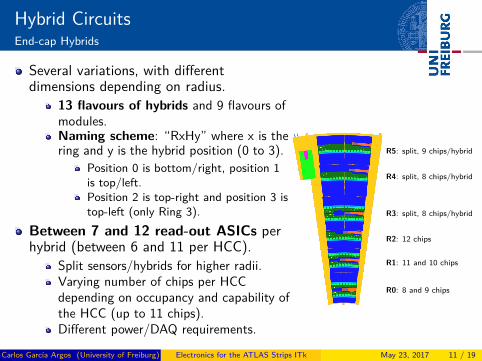
Several variations, with differentdimensions depending on radius.
13 flavours of hybrids and 9 flavours ofmodules.Naming scheme: “RxHy” where x is thering and y is the hybrid position (0 to 3).
Position 0 is bottom/right, position 1is top/left.Position 2 is top-right and position 3 istop-left (only Ring 3).
Between 7 and 12 read-out ASICs perhybrid (between 6 and 11 per HCC).
Split sensors/hybrids for higher radii.Varying number of chips per HCCdepending on occupancy and capability ofthe HCC (up to 11 chips).Different power/DAQ requirements.
R5: split, 9 chips/hybrid
R4: split, 8 chips/hybrid
R3: split, 8 chips/hybrid
R2: 12 chips
R1: 11 and 10 chips
R0: 8 and 9 chips
Carlos Garcıa Argos (University of Freiburg) Electronics for the ATLAS Strips ITk May 23, 2017 11 / 19

ModulesIntroduction
The hybrid is glued on sensor withnon-conductive glue.Power-board glued on sensor next to thehybrid(s).Wire-bonds from ASICs to strips and frompower-board to hybrid.
Power-board not needed for initial prototypes.Read-out from one side of the module toDAQ.
Power and data come from opposite sides ofthe module.
Carlos Garcıa Argos (University of Freiburg) Electronics for the ATLAS Strips ITk May 23, 2017 12 / 19

ModulesBarrel Long and Short Strips
Two flavours of barrel moduleprototypes:
Short strips (SS): two hybrids on ashort strips (2.5 cm) sensor.Long strips (LS): one hybrid on ashort strips sensor, strips segmentsconnected together to have longstrips.
Initially built and tested on a singlemodule test-frame.
Power and data come via IDCconnectors.
Now also tested on a bus-tapetogether with other modules.
[ENC (Equivalent Noise Charge) or noise is measured in electrons,Gain is measured in mV/fC.]
LH ENC=623 Gain=92RH ENC=621 Gain=92
Long Strips ENC=905 Gain=87
Short Strips ENC=654 Gain=87
Carlos Garcıa Argos (University of Freiburg) Electronics for the ATLAS Strips ITk May 23, 2017 13 / 19
ModulesEnd-cap Modules
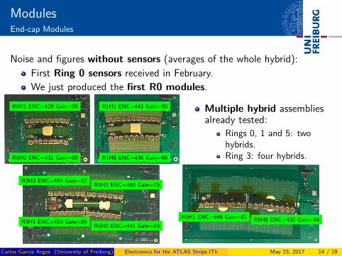
Noise and figures without sensors (averages of the whole hybrid):First Ring 0 sensors received in February.We just produced the first R0 modules.
R0H0 ENC=431 Gain=90
R0H1 ENC=429 Gain=89
R1H0 ENC=436 Gain=89
R1H1 ENC=442 Gain=90 Multiple hybrid assembliesalready tested:
Rings 0, 1 and 5: twohybrids.Ring 3: four hybrids.
R3H0 ENC=441 Gain=83R3H1 ENC=453 Gain=80
R3H2 ENC=460 Gain=79R3H3 ENC=454 Gain=82
R5H0 ENC=430 Gain=84R5H1 ENC=446 Gain=81
Carlos Garcıa Argos (University of Freiburg) Electronics for the ATLAS Strips ITk May 23, 2017 14 / 19

ModulesEnd-cap Modules
First Ring 0 module.Currently in test-beam at DESY.Sensor has 4 stripssegments with differentstrip lengths:
First (top) is ≈ 30 mm,read out by R0H1.Second is ≈ 27.5 mm,read out by R0H1.Third is ≈ 22.5 mm,read out by R0H0.Fourth (bottom) is≈ 17.5 mm, read out byR0H0.
R0H1 long ENC=779 Gain=92
R0H1 short ENC=773 Gain=91
R0H0 long ENC=720 Gain=91
R0H0 short ENC=624 Gain=90
Noise and gain are consistent with previous barrel prototypes.Carlos Garcıa Argos (University of Freiburg) Electronics for the ATLAS Strips ITk May 23, 2017 15 / 19

ModulesModule Irradiations and Test-Beam
Test-beams at DESY and CERN with full Long Strips barrelmodules in 2016.
DESY with 4 to 4.8 GeV electrons, non irradiated module.CERN with 120 GeV pions, a proton irradiated module to8× 1014 neq/cm2 (end-of-life).
Next: end-cap Ring 0 modules. Same as with the barrel modules,taking place this year.
Carlos Garcıa Argos (University of Freiburg) Electronics for the ATLAS Strips ITk May 23, 2017 16 / 19

ModulesStave of Modules
Four modules per side of thestave (out of 13).Power-boards for LV and HVdistribution.Bus-tape for data and powerdistribution fromEnd-of-Stave.
Presented in the next talk.Noise performance is fair forall modules.
Carlos Garcıa Argos (University of Freiburg) Electronics for the ATLAS Strips ITk May 23, 2017 17 / 19

ABCStar and HCCStar
HCC
ABC
ABC
ABC
ABC
ABC
ABC
ABC
ABC
ABC
ABC
HCCStar
ABCStar
ABCStar
ABCStar
ABCStar
ABCStar
ABCStar
ABCStar
ABCStar
ABCStar
ABCStar
Evolution of the current ABC130 andHCC130 chips, 130 nm process.Final read-out chip design for the ITk.Change in the read-out architectureto point-to-point links between eachABCStar and the HCCStar.Modifications in the front-end.
Prototype of preamplifier-shaper-discriminator with 32 channels.Higher initial noise than ABC130,lower noise with irradiation.
First production: 2017Q4.
Noise measurements for different inputcapacitance, ABC130 and
ABCStar prototypes.
Carlos Garcıa Argos (University of Freiburg) Electronics for the ATLAS Strips ITk May 23, 2017 18 / 19
Conclusions
ITk strips detector design and R&D well advanced.New Front-End development almost finished and preparing forpre-production.First barrel modules have been tested and show good end-of-lifeperformance.The first multi-module structure (stave) is being built and tested.The first end-cap module is about to be tested at DESY.And a second one will be irradiated and tested at CERN.
Carlos Garcıa Argos (University of Freiburg) Electronics for the ATLAS Strips ITk May 23, 2017 19 / 19