Module 1m.3 B1B2 Rev 00
42
Module 1 – MATHEMATICS Sub Module 1.3 – GEOMETRY CATEGORY B1/B2 – MECHANICAL/AVIONICS MODULE 1 SUB MODULE 1.3 GEOMETRY For Training Purposes Only Rev. 00 Oct 2006 1.3
-
Upload
humayun-yousaf -
Category
Documents
-
view
243 -
download
0
Transcript of Module 1m.3 B1B2 Rev 00
7/27/2019 Module 1m.3 B1B2 Rev 00
http://slidepdf.com/reader/full/module-1m3-b1b2-rev-00 1/42
Module 1 – MATHEMATICS
Sub Module 1.3 – GEOMETRY CATEGORY B1/B2 – MECHANICAL/AVIONICS
MODULE 1
SUB MODULE 1.3
GEOMETRY
For Training Purposes Only
Rev. 00 Oct 2006
1.3

7/27/2019 Module 1m.3 B1B2 Rev 00
http://slidepdf.com/reader/full/module-1m3-b1b2-rev-00 2/42

7/27/2019 Module 1m.3 B1B2 Rev 00
http://slidepdf.com/reader/full/module-1m3-b1b2-rev-00 3/42
1
For Training Purposes Only
Module 1 – MATHEMATICS
Sub Module 1.3 – GEOMETRY CATEGORY B1/B2 – MECHANICAL/AVIONICS
Rev. 00 Oct 2006
1.3
“The training notes and diagrams arecompiled by SriLankan Technical Training and although comprehensive in detail, theyare intended for use only with a Course ofinstruction. When compiled, they are as up
to date as possible, and amendments to thetraining notes and diagrams will NOT beissued”.

7/27/2019 Module 1m.3 B1B2 Rev 00
http://slidepdf.com/reader/full/module-1m3-b1b2-rev-00 4/42
Module 1 – MATHEMATICS
Sub Module 1.3 – GEOMETRY CATEGORY B1/B2 – MECHANICAL/AVIONICS
GEOMETRY
INTRODUCTIONPlane geometry is further divided into
The word geometry is derived from geo, a Greek word meaningearth, and metria, meaning measurement. Ancient Egyptianswere perhaps the first people to study geometry. They were
mainly concerned with problems of finding areas of rectangular figures. Later Babylonians also studied the problems of findingareas of various rectilinear figures. Both the Egyptians andBabylonians used geometry for practical purposes. However,they did not develop it as a systematic science.
Theoretical geometry consisting of theorems
and
Practical geometry consisting of problems.
Any separate geometrical operation, whether a discussion or aconstruction, is called a proposition.
It is desirable to tell the importance of the study of geometry.Primarily geometry teaches you how to reason. The habit of correct thinking acquired in its study is beneficial to all. By its
study you will be able to converse more logically and read with agreater understanding.
A theorem is a proposition in which a geometrical fact is provedby methodical reasoning.
A problem is a proposition in which a geometrical figure is to beactually constructed.
In this section we shall not enter into the details of plane or solidgeometry. However, we shall examine the fundamentals, of each.
So we may say that geometry literally means the measurementof the earth or land. Actually, geometry deals with themeasurement of areas, volumes, and distances, so the name,geometry, is descriptive of the mathematical science, which itdenotes.
There are two general types of geometry: that dealing withplane surfaces, called plane geometry, and that dealing withthree-dimensional objects, called solid geometry.
2
For Training Purposes Only
Rev. 00 Oct 2006
1.3

7/27/2019 Module 1m.3 B1B2 Rev 00
http://slidepdf.com/reader/full/module-1m3-b1b2-rev-00 5/42
Module 1 – MATHEMATICS
Sub Module 1.3 – GEOMETRY CATEGORY B1/B2 – MECHANICAL/AVIONICS
DEFINITIONS Surface: A surface has no thickness but has length andbreath.
The study of geometry requires the use of many terms, whichare not used in everyday conversation, so it is necessary that webecome familiar ii with these terms .For this purpose havepresented a number of definitions for common geometric terms.
SurfacePoint: A point is that which has no length, breadth, or thickness but has only position. Plane or plane surface: A plane or plane surface may be defined
in several ways as follows:
A surface such that a straight line that joins anytwo of its points lie wholly in that surface.Point
A two-dimensional extent of zero curvature.Line: A line has no breadth or thickness but has length.
A surface any intersection, of which by a likesurface is a straight line.
Straight Line: A line having the same direction throughout itslength, if a portion of straight line is placed so that
both ends fall within the ends of the remainingpart, the portion must lie wholly within the line.
Line
Straight Line
3
For Training Purposes Only
Rev. 00 Oct 2006
1.3

7/27/2019 Module 1m.3 B1B2 Rev 00
http://slidepdf.com/reader/full/module-1m3-b1b2-rev-00 6/42
Module 1 – MATHEMATICS
Sub Module 1.3 – GEOMETRY CATEGORY B1/B2 – MECHANICAL/AVIONICS
Solid : A solid, in the geometric sense, is that which hasthree dimensions, that is, length, breadth, andthickness.
Broken Line: A line consisting of a number of differentsegments of straight lines.
Equal Lines: Two lines are equal if, when placed one upon theother, all corresponding points coincide.
Curved Line: A line which continuously change direction.
Angle: An angle is the opening between two straightlines drawn .in different directions from the same.
Right Angle: An angle which is one-fourth of a circle, that is,
90°.
Broken Line
Angle
Solid
Equal Lines
Curved LineRight Angle
4
For Training Purposes Only
Rev. 00 Oct 2006
1.3

7/27/2019 Module 1m.3 B1B2 Rev 00
http://slidepdf.com/reader/full/module-1m3-b1b2-rev-00 7/42
Module 1 – MATHEMATICS
Sub Module 1.3 – GEOMETRY CATEGORY B1/B2 – MECHANICAL/AVIONICS
Acute Angle: An angle which is less than a right angle.
Vertex of an Angle: The common point from which the two sidesof an angle proceed
Obtuse Angle: An angle, which is more than a right angle butless than a straight angle
Straight Angle: An Angle of whose sides from a straight line, that
is, an angle of 180°
Reflex Angle: It is any angle that is larger than a straight angle
Vertex
Acute angle
Reflex Angles
Bisector : A bisector is a point, line, or surface, whichdivides a magnitude into two equal parts.
Bisector
Obtuse Angle
Adjacent Angles: Two angles having a common side and thesame vertex.
Adjacent Angles 180º
Straight Angle
5
For Training Purposes Only
Rev. 00 Oct 2006
1.3

7/27/2019 Module 1m.3 B1B2 Rev 00
http://slidepdf.com/reader/full/module-1m3-b1b2-rev-00 8/42
Module 1 – MATHEMATICS
Sub Module 1.3 – GEOMETRY CATEGORY B1/B2 – MECHANICAL/AVIONICS
Vertical Angles: Two angles with the same vertex and with sidesthat are prolongations of the sides of each other.
Perpendicular Line: Straight line, which makes a 90° with
another straight line and is perpendicular to theline.
Circle: A closed curve all portions of which are in thesame plane and equidistant from the same point.
Chord
Diameter : The length of a line passing through the center of a circle and limited at each end by the circle.
Radius: A straight line from the center of circle to thecircle perimeter. The radius is equal to one-half the diameter.
Circumference Length of the imaginary line enclosing the areaof the circle
Arc : Any portion of a circle.
Sector : The area within a circle bounded by two radiiand the arc connecting the ends of the radii.
Chord . A straight line within a circle connecting twopoints on the circle.
Vertical Angles
90º 90º
Perpendicular Line
Circle
Radius
Arc
Sector Diameter
Circumference
6
For Training Purposes Only
Rev. 00 Oct 2006
1.3
7/27/2019 Module 1m.3 B1B2 Rev 00
http://slidepdf.com/reader/full/module-1m3-b1b2-rev-00 9/42
Module 1 – MATHEMATICS
Sub Module 1.3 – GEOMETRY CATEGORY B1/B2 – MECHANICAL/AVIONICS
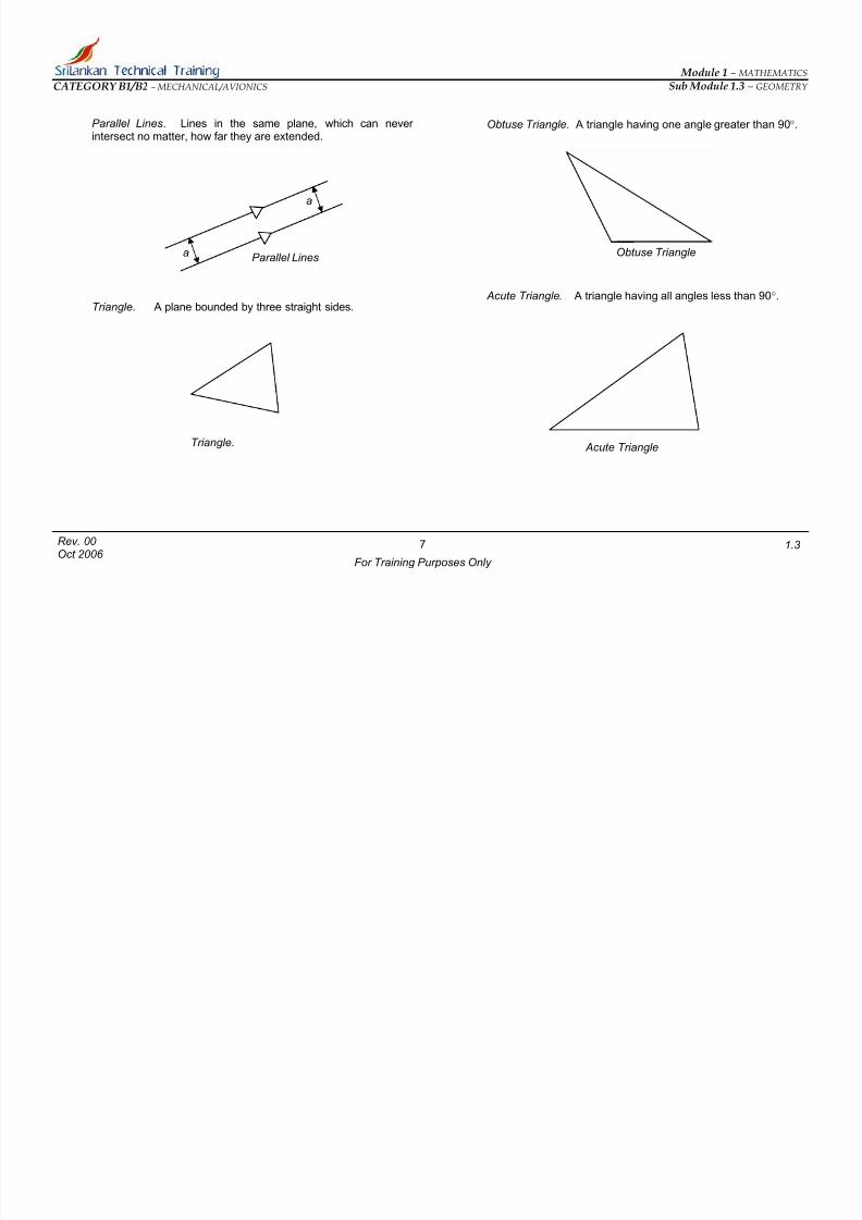
Parallel Lines. Lines in the same plane, which can never intersect no matter, how far they are extended.
Triangle. A plane bounded by three straight sides.
Obtuse Triangle. A triangle having one angle greater than 90°.
a
Obtuse Trianglea Parallel Lines
Acute Triangle. A triangle having all angles less than 90°.
Triangle. Acute Triangle
7
For Training Purposes Only
Rev. 00 Oct 2006
1.3
7/27/2019 Module 1m.3 B1B2 Rev 00
http://slidepdf.com/reader/full/module-1m3-b1b2-rev-00 10/42
Module 1 – MATHEMATICS
Sub Module 1.3 – GEOMETRY CATEGORY B1/B2 – MECHANICAL/AVIONICS
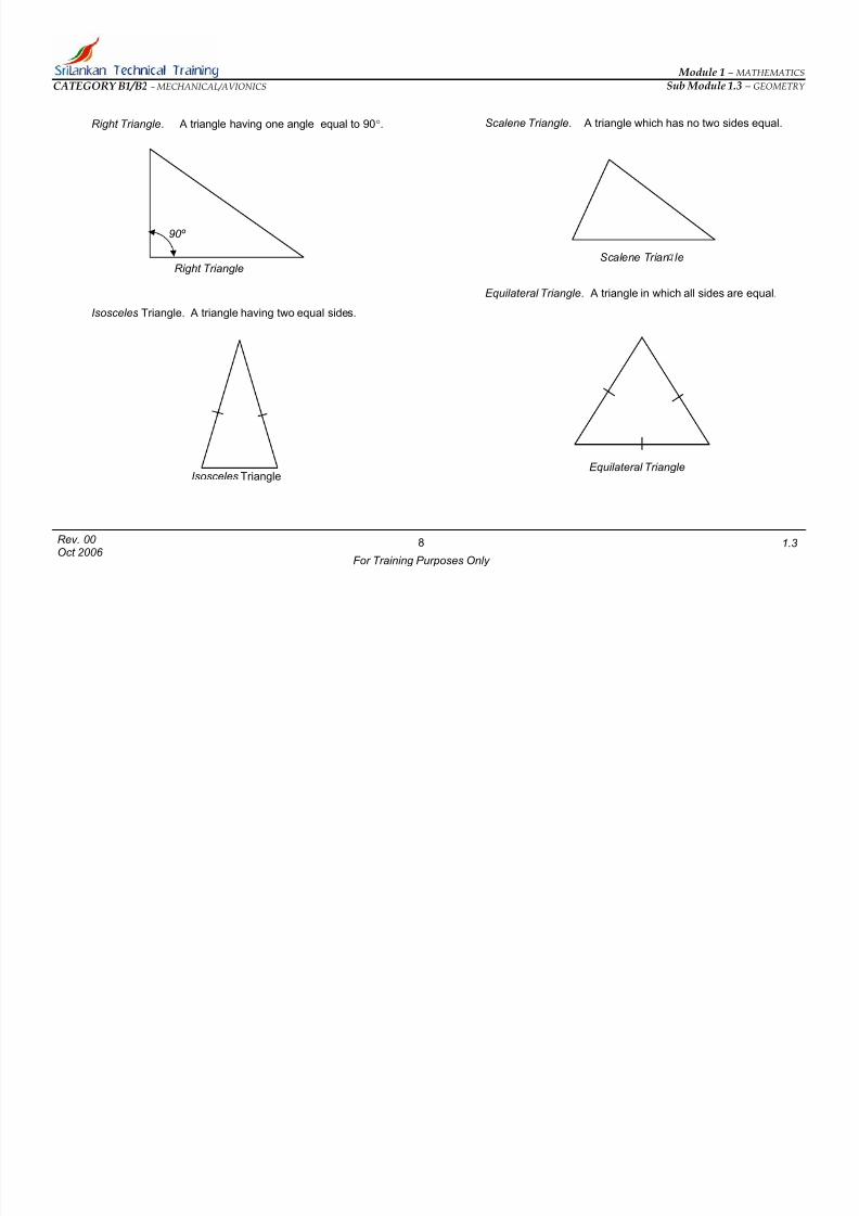
Right Triangle. A triangle having one angle equal to 90°.
Isosceles Triangle. A triangle having two equal sides.
Scalene Triangle. A triangle which has no two sides equal.
90º
Scalene Trian leRight Triangle
Equilateral Triangle. A triangle in which all sides are equal.
Equilateral Triangle Isosceles Triangle
8
For Training Purposes Only
Rev. 00 Oct 2006
1.3

7/27/2019 Module 1m.3 B1B2 Rev 00
http://slidepdf.com/reader/full/module-1m3-b1b2-rev-00 11/42
Module 1 – MATHEMATICS
Sub Module 1.3 – GEOMETRY CATEGORY B1/B2 – MECHANICAL/AVIONICS
Square. A plane figure bounded by four equal sides and havingfour right angles.
Parallelogram. A four-sided plane figure whose opposite sides
are equal and parallel.
Trapezium. A four-sided plane figure with two parallel sides andtwo sides which are not parallel.
Rectangle. A four-sided plane figure having four right angles.
Additional terms are also used in geometry; however, aboveillustration and terms used will provide a basis for continuing witha study of the principles of geometry.
90º
90º
90º
90º Trapezium
S uare
90º 90º
90º 90º
Parallelogram.Rectangle
9
For Training Purposes Only
Rev. 00 Oct 2006
1.3
7/27/2019 Module 1m.3 B1B2 Rev 00
http://slidepdf.com/reader/full/module-1m3-b1b2-rev-00 12/42
Module 1 – MATHEMATICS
Sub Module 1.3 – GEOMETRY CATEGORY B1/B2 – MECHANICAL/AVIONICS
SYMBOLS USED IN GEOMETRY
Certain symbols are used in geometry to indicate terms andrelationships. The following listing gives the most commonlyused symbols :
= Equality
Is congruent to
> Is greater than
< Is less than
// Parallel
⊥ Perpendicular
≈ Approximate (1Y)
∡ Angle
∆ Triangle
Parallelogram
⃞ Rectangle
⃝ Circle
∴ Therefore
∵ Since
AXIOMS
The proofs of geometrical propositions or theorems are basedupon statements justified by reasons. We have already studiedabout axioms in our previous mathematics lessons. However, itis better to have some additional knowledge about axioms. Self-evident truths, called axioms, are used to justify or prove thestatements. The most important axioms are the following:
≡ • Equals added to equals give equal sums.
• When equals are subtracted from equals, the remaindersare equal.
• When equals multiply equals, the products are equal.
• When equals divide equals, the quotients are equal.
• Things equal to the same thing are equal to each other.• The whole is greater than any of its parts and is equal to
the sum of its parts.
• Like. powers or like positive roots of equals are equal.
• Equals may be substituted for equals .
• Only one straight line can be drawn between two points .
• The shortest distance between two points is a straightline.
10
For Training Purposes Only
Rev. 00 Oct 2006
1.3

7/27/2019 Module 1m.3 B1B2 Rev 00
http://slidepdf.com/reader/full/module-1m3-b1b2-rev-00 13/42
Module 1 – MATHEMATICS
Sub Module 1.3 – GEOMETRY CATEGORY B1/B2 – MECHANICAL/AVIONICS
POSTULATES AND COROLLARIES
Following the axioms are other statements which are apparentlytrue and which may be proved easily. These are calledpostulates or corollaries. Corollaries are usually based upon astatement previously proved. A postulate needs no proof because it is self-evident, however, it is a specific statement of geometrical fact rather than a general statement.
Some commonly stated postulates are the following:
• Two angles are equal if they can be made to coincide.
• A geometric figure may be moved without altering itssize: or shape.
• Straight angles are equal.
•Right angles are equal. ,
• A circle may be described with any point as its center andany line as a radius.
11
For Training Purposes Only
Rev. 00 Oct 2006
1.3

7/27/2019 Module 1m.3 B1B2 Rev 00
http://slidepdf.com/reader/full/module-1m3-b1b2-rev-00 14/42
Module 1 – MATHEMATICS
Sub Module 1.3 – GEOMETRY CATEGORY B1/B2 – MECHANICAL/AVIONICS
SIMPLE GEOMETRICAL CONSTRUCTIONS
It is possible with a compass, a ruler, and a protractor toconstruct many geometrical figures, which accurately fulfill their definitions or descriptions.
In most cases the protractor is not needed.
But it should be remembered that to make complex engineeringdrawings we need to have sophisticated devices such asdrawing boards, Engineer’s rulers, different types of papers etc.Knowledge of simple geometric constructions will be a greatassistance for a beginner of engineering drawings.
Under this lesson we will study the methods of dividing line into
given number of equal parts, bisecting lines and angles, drawinglines perpendicular to lines, copying angles and triangles.
BISECT A STRAIGHT LINE.
The straight line given is ab. To bisect the given line, adjust thecompass so that it spans a greater distance than one-half thelength of the line. Place the point of the compass on A and strikean arc CDE as shown. Without altering the adjustment of thecompass, using B as a center, strike a second arc FGH . Connectthe points J and K with a straight line. The line JK bisects thegiven line AB .
E
F C
J Bisector
B AG D
K
H
12
For Training Purposes Only
Rev. 00 Oct 2006
1.3

7/27/2019 Module 1m.3 B1B2 Rev 00
http://slidepdf.com/reader/full/module-1m3-b1b2-rev-00 15/42
Module 1 – MATHEMATICS
Sub Module 1.3 – GEOMETRY CATEGORY B1/B2 – MECHANICAL/AVIONICS
DRAWING A PERPENDICULAR FROM A POINT TO A LINE
In this case we are going to draw a perpendicular to a line from agiven point. The point given is P and the straight line is AB. Fromthe point P use the compass to strike arcs at A and B, using thesame radius in each case. Then from the points A and B,
maintaining the adjustment of the compass, strike intersectingarcs at C . Connect the points P and C with a straight line. Theline PC is perpendicular to AB.
DIVIDING A STRAIGHT LINE INTO NUMBER OF EQUALPARTS.
Let the line to be divided be AB. Assume that we need to divide AB into 5 equal parts. Draw another line from A or B. Divide thesecond line in to 5 equal parts using the compass. This can bedone by setting the compass to a fixed length and marking thisset distance along the line. Then connect the open end of AB to
the last marked point on the second line. After that draw linesparallel to the connecting lines starting from the other markedpoints to meet AB.
P
C
sr
q
A B
C
90º p
t
A B
13
For Training Purposes Only
Rev. 00 Oct 2006
1.3

7/27/2019 Module 1m.3 B1B2 Rev 00
http://slidepdf.com/reader/full/module-1m3-b1b2-rev-00 16/42
Module 1 – MATHEMATICS
Sub Module 1.3 – GEOMETRY CATEGORY B1/B2 – MECHANICAL/AVIONICS
BISECTING AN ANGLE
Let the angle given be AOB. Place the point of a compass at O and strike arcs at A and B so that OA = OB. From the points A and B strike intersecting arcs with the same radius. Mark thepoint of intersection of these arcs as C. Draw the line OC. OC is
then the bisector of the angle.
DUPLICATE A GIVEN ANGLE.
Let the given angle be ACB. Draw a line and mark it DX . Strikean arc AB having C as the center. Taking D as the center andCB as the distance, draw an arc DE using the radius AC . Usingthe distance AB as a radius and E as the center, strike an arc to
intersect the previous arc. Mark the intersecting point of the arcsas F . Connect D and F . Angle ACB = angle FDE .
F A A C
O BC
BD
E X
14
For Training Purposes Only
Rev. 00 Oct 2006
1.3

7/27/2019 Module 1m.3 B1B2 Rev 00
http://slidepdf.com/reader/full/module-1m3-b1b2-rev-00 17/42
Module 1 – MATHEMATICS
Sub Module 1.3 – GEOMETRY CATEGORY B1/B2 – MECHANICAL/AVIONICS
DUPLICATE A GIVEN TRIANGLE
Let the given triangle be ABC. Draw a straight line DX . Using AB as a radius and D as the center, draw an arc cutting DX at E .Using AC as a radius and D as a center, draw an arc in thevicinity of F . Using CB as the radius and B as a center, draw an
arc to intersect the other arc at F . Draw the lines DF and EF .DEF is the duplicate triangle.
C F
A B E X D
15
For Training Purposes Only
Rev. 00 Oct 2006
1.3
7/27/2019 Module 1m.3 B1B2 Rev 00
http://slidepdf.com/reader/full/module-1m3-b1b2-rev-00 18/42
Module 1 – MATHEMATICS
Sub Module 1.3 – GEOMETRY CATEGORY B1/B2 – MECHANICAL/AVIONICS
ANGLE RELATIONSHIPS
.
There are various specific relationships among angles, whichshould be observed and understood. Some of these are given inthe following statements:
• When the sum of two angles is 90°, the angles are said
to be complementary, or complements of each other
• When the sum of the angles is 180°, the angles are saidto be supplementary or supplements of each other.
• When two straight lines cross each other, vertical anglesare formed and the vertical angles are equal.
• When a straight line meets another, supplementary
angles are formed.• Complements of an angle are equal
• Supplements of an angle are equal
16
For Training Purposes Only
Rev. 00 Oct 2006
1.3

7/27/2019 Module 1m.3 B1B2 Rev 00
http://slidepdf.com/reader/full/module-1m3-b1b2-rev-00 19/42
Module 1 – MATHEMATICS
Sub Module 1.3 – GEOMETRY CATEGORY B1/B2 – MECHANICAL/AVIONICS
PARALLEL LINES
As previously explained, parallel lines are lines in the sameplane, which cannot meet, no matter how far they are extended.
A straight line, which cuts across a pair of parallel lines, is calleda transversal . The transversal makes angles with the parallel
lines as shown below
In the foregoing diagram the angles are named according to their position in the diagram.
• Angles a,b,g, and h are called exterior angles.
• Angles c,d,e, and f are called interior angles.
•
The pairs of angles a and h, and b and g are calledalternate exterior angles.
• The pairs of angles c and f , and e and d are calledalternate interior angles
• The pairs a and e, b and f , c and g , d and h are calledcorresponding angles, or they may be referred to asinterior-exterior angles.
• When parallel lines are cut by a transversal as shown inthe diagram,
• Alternate interior angles are equal.
• Alternate exterior angles are equal.
• Corresponding angles are equal.
• Exterior angles on the same side of the transversal aresupplementary.
• Interior angles on the same side of the transversal aresupplementary.
a
A few other facts concerning parallel lines are as follows
• If two lines are perpendicular to the same line, they areparallel to each other.
• Through a given point only one line can be drawn parallelto another.
• If two straight lines in the same plane cannot intersect,regardless of how far they are extended, they areparallel.
• Two intersecting lines cannot both be parallel to a third
line.• A straight line perpendicular to one of two parallel lines is
also perpendicular to the other.
d b
c
ehf
g
17
For Training Purposes Only
Rev. 00 Oct 2006
1.3

7/27/2019 Module 1m.3 B1B2 Rev 00
http://slidepdf.com/reader/full/module-1m3-b1b2-rev-00 20/42
Module 1 – MATHEMATICS
Sub Module 1.3 – GEOMETRY CATEGORY B1/B2 – MECHANICAL/AVIONICS
TRIANGLES
According to their construction and dimensions, triangles havecertain relationships with one another. The conditions of congruency are particularly important to remember. These maybe stated as below.
• If two angles and the included side of one triangle are
equal respectively to two angles and the included, side of another triangle, the triangles are congruent. That is, theyare identical in size and shape.
• If two sides and the included angle of one triangle areequal respectively to two sides and the included angle of another triangle, the triangles are congruent
If three sides of one triangle are equal respectively to three sidesof another triangle, the triangles are congruent.
• The angles opposite the equal sides of an isoscelestriangle are equal. On the other hand if two angles of atriangle are equal, the triangle is isosceles.
• Also it should be remembered that the sum of the anglesof a triangle is equal to 180˚
A
B C
D
E F
≡
A
B C
D
E F
≡
A D
≡E B F C
A
C B
18
For Training Purposes Only
Rev. 00 Oct 2006
1.3

7/27/2019 Module 1m.3 B1B2 Rev 00
http://slidepdf.com/reader/full/module-1m3-b1b2-rev-00 21/42
Module 1 – MATHEMATICS
Sub Module 1.3 – GEOMETRY CATEGORY B1/B2 – MECHANICAL/AVIONICS
RIGHT TRIANGLES
Theorems relating to right triangles are similar to those for other triangles. However, the fact that the right angles are equalmakes it possible to determine congruency with fewer givenparts. Some of the theorem (rules) for right triangles are givenbelow:
• If two right triangles have one side and one angle equalrespectively, they are congruent.
• If the two sides adjacent to the right angles in two righttriangles are equal, the triangles are congruent.
• The square of the hypotenuse in a right triangle is equalto the sum of the squares of the other two sides (thePythagorean theorem).
PARALLELOGRAMS
As previously explained, a parallelogram is a four-sided figure(quadrilateral) whose opposite sides are parallel. The mostimportant rules pertaining to parallelograms are stated below.
• The opposite sides of a parallelogram are equal
• The opposite angles of a parallelogram are equal, and
consecutive angles are supplementary.
• A quadrilateral is a parallelogram if the opposite sides areequal.
• A quadrilateral is a parallelogram if two of the oppositesides are equal and parallel.
• The diagonals of a parallelogram bisect each other.
A Hypotenuse • Parallelograms are congruent if two adjacent sides andthe included angle are equal.
Oppositeside A B
Base
B C
D C
(AC)2 = (AB)2 +(AC)2 Diagonal
19
For Training Purposes Only
Rev. 00 Oct 2006
1.3

7/27/2019 Module 1m.3 B1B2 Rev 00
http://slidepdf.com/reader/full/module-1m3-b1b2-rev-00 22/42
Module 1 – MATHEMATICS
Sub Module 1.3 – GEOMETRY CATEGORY B1/B2 – MECHANICAL/AVIONICS
POLY GONS
A polygon is a plane, closed figure bounded by straight lines joined end to end. Hence, a polygon may have any number of sides from three upward. Polygons are given names descriptiveof their characteristic number of sides. A four-sided figure is aquadrilateral, a five-sided figure is a pentagon, a six-sided figureis a hexagon, a seven-sided figure is a heptagon etc.
A regular polygon has all sides and angles equal.
RULES OF POLYGON
• The sum of the interior angles of a polygon is equal to180˚ times the number of sides less two. Thus if apolygon has n number of sides the sum of interior anglesare
180 ̊ (n-2)
Hence for a pentagon the sum of interior angles is
180 ̊ (5-2) = 180 ̊ x3 = 540 ̊
Bb
• When a regular polygon has n sides, each interior angleis equal to:
n
n )2(2 −x90 ̊ where n = the number of sides.
aC
A c
e D • If the sides of a polygon are extended consecutively inthe same direction, the sum of the exterior angles thusformed will be equal to 360 °.
d E
20
For Training Purposes Only
Rev. 00 Oct 2006
1.3

7/27/2019 Module 1m.3 B1B2 Rev 00
http://slidepdf.com/reader/full/module-1m3-b1b2-rev-00 23/42
Module 1 – MATHEMATICS
Sub Module 1.3 – GEOMETRY CATEGORY B1/B2 – MECHANICAL/AVIONICS
CIRCLES
A circle is a closed curve such that all points on the curve areequidistant from a fixed point within the circle.
Lets see some useful terms related to circle. We have alreadydiscussed some of these terms at the beginning of this module
• A minor arc is one of less than 180°.
• A major arc is one of more than 180°.• A semicircle is an arc of 180°.
• A quadrant is a sector with an arc of 90°.
• A chord is a straight line in a circle connecting two pointson the circle.
• A tangent is a straight line of unlimited length, which has
only one point in common with a circle.• A secant is a straight line, which intersects a circle.
• An inscribed angle in a circle is an angle whose vertex ison the circle.
• A central angle in a circle is an angle whose vertex is atthe center of the circle.
RULES FOR CIRCLES
• In the same circle or in equal circles, equal central anglesintercept equal arcs and equal arcs subtend equal centralangles.
X A
B Y P O
• All radii of the same circle or of equal circles are equal.• In the same circle or equal circles, equal chords subtend
equal arcs.
• A line perpendicular; to a chord and passing through thecenter of a circle bisects the chord and the arcssubtended by it
O
A B
21
For Training Purposes Only
Rev. 00 Oct 2006
1.3
7/27/2019 Module 1m.3 B1B2 Rev 00
http://slidepdf.com/reader/full/module-1m3-b1b2-rev-00 24/42
Module 1 – MATHEMATICS
Sub Module 1.3 – GEOMETRY CATEGORY B1/B2 – MECHANICAL/AVIONICS
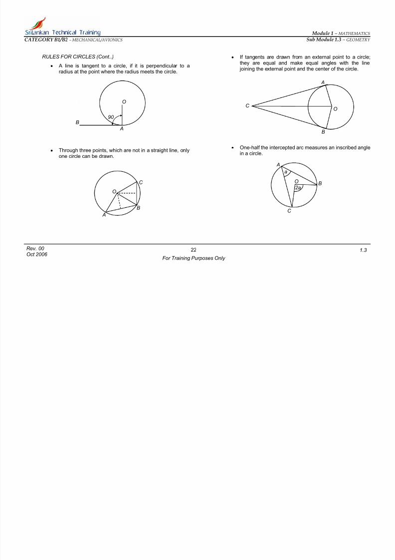
RULES FOR CIRCLES (Cont..)
• A line is tangent to a circle, if it is perpendicular to aradius at the point where the radius meets the circle.
• Through three points, which are not in a straight line, onlyone circle can be drawn.
• If tangents are drawn from an external point to a circle;they are equal and make equal angles with the line joining the external point and the center of the circle.
• One-half the intercepted arc measures an inscribed anglein a circle.
A
A
B
O
90 ̊
A
B
O
C
B
OC
A
BO
C
a
2a
22
For Training Purposes Only
Rev. 00 Oct 2006
1.3

7/27/2019 Module 1m.3 B1B2 Rev 00
http://slidepdf.com/reader/full/module-1m3-b1b2-rev-00 25/42
Module 1 – MATHEMATICS
Sub Module 1.3 – GEOMETRY CATEGORY B1/B2 – MECHANICAL/AVIONICS
Any angle inscribed in a semicircle is a right angle.
In this case AB is a diameter which divide the circle into twohalve. Angles ABC and ADB are inscribed angles in thesemicircle. These angles are right angles.
A BO
C D
23
For Training Purposes Only
Rev. 00 Oct 2006
1.3

7/27/2019 Module 1m.3 B1B2 Rev 00
http://slidepdf.com/reader/full/module-1m3-b1b2-rev-00 26/42
Module 1 – MATHEMATICS
Sub Module 1.3 – GEOMETRY CATEGORY B1/B2 – MECHANICAL/AVIONICS
GRAPHICAL REPRESENTATIONS
In this chapter we consider the ways of presenting numericalinformation in pictorial, diagrammatic and graphical forms. Thissubject is known generally as graphical representation. Itprovides in almost all cases a much clearer presentation of results and a much easier means of making assessments than
can normally be gained from trying to shift through a mass of data. Graphs, charts, diagrams are extensively employed in bothscientific and non-scientific disciplines from plotting experimentalresults to assessing a company’s trading performance-fromdemonstrating the properties of a mathematical equation or formula to predicting energy requirements in the twenty-firstcentury, from solving equations to representing medicalstatistics.
A chart may be designed to provide almost any type of information. Charts are used to present pictorial data, numericaldata, graphical data and various other types of information.
Consider the figure below to explain the framework used to plotpoints in the graph. The pair of reference lines X'OX and Y'OY,which are drawn at right angles to each other, are known asaxes. The horizontal reference line X'OX is known as the
horizontal axis or the x-axis. The vertical reference line Y'OY isknown as the vertical or y-axis. Appropriate scales are markedon these axes-it is up to us to decide the most suitable scale for each axis for the problem in hand. In the figure for simplicity,both the x and y-axes are marked at unit intervals to cover arange -7 through to +7. The zero point O at the intersection of the two axes corresponds to a point x = 0, y = 0. This point isknown as the origin.
Any point defining a given pair of related values is plotted withrespect to the two axes. For example, consider the plotting of thefollowing points.
Point A defined by x = 4, y = 4
Move 4 units along the x-axis in the positive x direction (to theright from the origin); move 4 units in the positive y direction
(upwards). The point corresponding to x = 4, y = 4 is marked inas A in the figure.
Points are usually marked on the graph paper by a dot. A smallcircle may be drawn around the dot point to aid rapid recognition. Alternatively a small cross may be used.
A
Y axis7
6
5
0 1 2 3 4 5
Origin 4
3
2
1
X axis
-7 -6 -5 -4 -3 -2 -1 6 7
-1
-2
-3-4
-5
-6
-7
Y
Y’
X’
(O)
X
24
For Training Purposes Only
Rev. 00 Oct 2006
1.3

7/27/2019 Module 1m.3 B1B2 Rev 00
http://slidepdf.com/reader/full/module-1m3-b1b2-rev-00 27/42
Module 1 – MATHEMATICS
Sub Module 1.3 – GEOMETRY CATEGORY B1/B2 – MECHANICAL/AVIONICS
Similarly any point like point A can be marked on the graph. Soin this case we have marked point B (5, 6), point C (2,1), pointsD (-2,-2), point E (-3,-4), and point F (-7,-4). It should beunderstood that in this graph the dotted lines are shown froclarity. They are normally not drawn.
After marking the required points, they are connected by a lineas it appear in the figure above. This line may be straight or anon-straight depending on the values we have selected.
0 1 2 3 4 5 6 7-1-2-3-4-5-6-7
1
2
3
4
5
6
7
-2
-3
-4
-5
-6
-7
-1
X axis
Y axis
A
E
D
C
F
B
25
For Training Purposes Only
Rev. 00 Oct 2006
1.3

7/27/2019 Module 1m.3 B1B2 Rev 00
http://slidepdf.com/reader/full/module-1m3-b1b2-rev-00 28/42
Module 1 – MATHEMATICS
Sub Module 1.3 – GEOMETRY CATEGORY B1/B2 – MECHANICAL/AVIONICS
GRAPHS
The term graph is normally applied to the line, straight or curved, which defines the relationship between two or morequantities. A "conventional" graph is constructed by plotting apair or number of related values as points on a piece of graphpaper and then drawing a "smooth” curve through the plottedpoints. In mathematics it is common practice to use x and y as
the symbols to denote two sets of related values. In introducinggraphs we will use x and y, but we could-and indeed will useother symbols most relevant to our particular problem.
For example, if the speed or time of flight of an airplanechanges, the distance traveled in a given time will change. Thisis illustrated in the graph in the next column. If any two of thevariables are known, the approximate value of the other can bequickly determined. The dotted line indicates how distance is
determined when speed and time are known. The value shownis 937.5 nautical miles.
DISTANCE – NAUTICAL MILES X 100
4.5
4.0
3.5
3.0
2.5
2.O
1.5
1.0
0.5
1 2 3 4 5 6 7 8 9 10 11 12 13 14 15 16 17 18 19 20
20
1918
17
16
15 14
D I S T A N C E – N A U T I C A L M I L E S X 1 0
0
S P E E D - K N O T S X
1 0 0
13
12
11
10
8
9
7
6
54
3
2
1
1 2 3 4 5
-
26
For Training Purposes Only
Rev. 00 Oct 2006
1.3

7/27/2019 Module 1m.3 B1B2 Rev 00
http://slidepdf.com/reader/full/module-1m3-b1b2-rev-00 29/42
Module 1 – MATHEMATICS
Sub Module 1.3 – GEOMETRY CATEGORY B1/B2 – MECHANICAL/AVIONICS
NATURE AND USE OF GRAPHS
A broken-line graph or a bar graph is used to show comparativequantitative data. The broken-line graph is useful to show trendsin quantitative data over a period of time. In the illustrationbelow the broken-line graph and bar graph provide the sameinformation. In this case, the graphs represent the number of engines completed in a large overhaul shop for each monthduring the year.
100
95
90
85
80
75
100
95
90
85
80
75
70
65
60
55
50
45
40
35
30
25
20
15
10
5
JAN FEB MAR APR MAY JUN JUL AUG SEP OCT NOV DEC
U
S C O M P L E T
N I T
E D
Broken line graph
70 E
65
60
55
50
45
4035
30
25
20
15
10
5
U
S
C O M P L E T
N I T
D
Bar graph
27
For Training Purposes Only
Rev. 00 Oct 2006
1.3
7/27/2019 Module 1m.3 B1B2 Rev 00
http://slidepdf.com/reader/full/module-1m3-b1b2-rev-00 30/42
Module 1 – MATHEMATICS
Sub Module 1.3 – GEOMETRY CATEGORY B1/B2 – MECHANICAL/AVIONICS
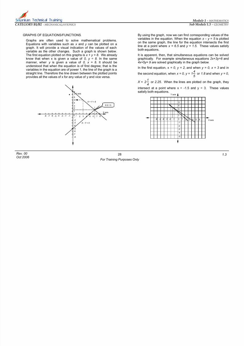
GRAPHS OF EQUATIONS/FUNCTIONS.
Graphs are often used to solve mathematical problems.Equations with variables such as x and y can be plotted on agraph. It will provide a visual indication of the values of eachvariable as the other changes. Such a graph is shown below.The first equation plotted on this graphs is x + y = 8 . We alreadyknow that when x is given a value of 0, y = 8. In the same
manner, when y is given a value of 0, x = 8 . It should beunderstood that when the equation is of first degree; that is thevariables in the equation are of power 1, the line of the graph is astraight line. Therefore the line drawn between the plotted pointsprovides all the values of x for any value of y and vice versa.
By using the graph, now we can find corresponding values of thevariables in the equation. When the equation x – y = 5 is plottedon the same graph, the line for the equation intersects the firstline at a point where x = 6.5 and y = 1.5 . These values satisfyboth equations.
It is apparent, then, that simultaneous equations can be solvedgraphically. For example simultaneous equations 2x+3y=6 and
4x+5y= 9 are solved graphically in the graph below.
In the first equation, x = 0, y = 2 , and when y = 0, x = 3 and in
the second equation, when x = 0, y =5
41 or 1.8 and when y = 0 ,
X =4
12 or 2.25. When the lines are plotted on the graph, they
intersect at a point where x = -1.5 and y = 3. These values
satisfy both equations.
7
X axis
-1
-7
-2-3-4-5-6-7 0 1 2 3 4 5 6
-2
-3-4
-5
-6
1
23
4
5
6
78 Y axis
-18-8
-8
Y axis
X + Y = 8 5
X - Y = 5
6.5 1.5 4
X axis
-1
-2-3-4-5-6 0
1
2 3 4 5 6
-2
3-
4-
-5
1
2
3
-1
28
For Training Purposes Only
Rev. 00 Oct 2006
1.3

7/27/2019 Module 1m.3 B1B2 Rev 00
http://slidepdf.com/reader/full/module-1m3-b1b2-rev-00 31/42
Module 1 – MATHEMATICS
Sub Module 1.3 – GEOMETRY CATEGORY B1/B2 – MECHANICAL/AVIONICS
CIRCULAR GRAPHS
Circular or “pie” graphs are used often to indicate a distributionof money. For example, the circle graphs shown in Figure belowindicate the distribution of the gross amount of money receivedby a general aviation agency during a year of operation. Eachsector of the circle represents a quantity of money.
NOMOGRAPHS
A nomograph, also called a monogram or alignmentchart, is a calculating chart with scales that contain values of three of more variables. The distances between the lines andthe scales on the lines are placed in such a manner that the user may employ a straightedge to line up two known values andobtain a third value. Nomographs are often used in computing
horsepower problems, cruise-control problems, and similar problems involving three or more variables.
MATERIALS & SUPPLIES 28.9%
EQUIPMENT & OPERATION 1.5%
PROFITS 4.3%
TAXES 11.3%
UTILITIES 4.5
LEASE 3.1%
29
For Training Purposes Only
Rev. 00 Oct 2006
1.3
7/27/2019 Module 1m.3 B1B2 Rev 00
http://slidepdf.com/reader/full/module-1m3-b1b2-rev-00 32/42
Module 1 – MATHEMATICS
Sub Module 1.3 – GEOMETRY CATEGORY B1/B2 – MECHANICAL/AVIONICS
TRIGONOMETRY
Trigonometry is the branch of mathematics, which makespossible the solution of unknown parts of a triangle. When thevalues of certain angles and sides of a triangle are known, it ispossible to determine the values of all the parts through the useof trigonometric processes.
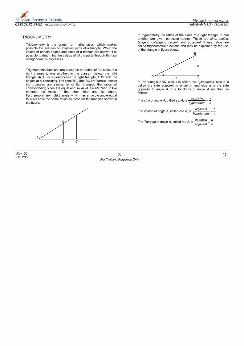
Trigonometric functions are based on the ratios of the sides of aright triangle to one another. In the diagram below, the righttriangle AB’C’ is superimposed on right triangle ABC with theangles at A coinciding. The lines B'C' and BC are parallel: hencethe triangles are similar. In similar triangles the ratios of corresponding sides are equal and so AB/AC = AB’ /AC' . In like
manner, the ratios of the other sides are also equal.Furthermore, any right triangle, which has an acute angle equalto A will have the same ratios as those for the triangles shown inthe figure.
In trigonometry the ratios of the sides of a right triangle to oneanother are given particular names. These are sine, cosine,tangent, cotangent, secant, and cosecant . These ratios arecalled trigonometric functions and may be explained by the useof the triangle in figure below.
B
c
a
A C
In the triangle ABC , side c is called the hypotenuse, side b iscalled the side adjacent to angle A, and side a is the sideopposite to angle A. The functions of angle A are then as
follows:
b
The sine of angle A, called sin A, isc
a
hypotenous
opposite=
The cosine of angle A, called cos A, isc
b
hypotenous
adjacent =
B
The Tangent of angle A, called tan A, is b
a
adjacent
opposite
= B’
A
C’ C
30
For Training Purposes Only
Rev. 00 Oct 2006
1.3
7/27/2019 Module 1m.3 B1B2 Rev 00
http://slidepdf.com/reader/full/module-1m3-b1b2-rev-00 33/42
Module 1 – MATHEMATICS
Sub Module 1.3 – GEOMETRY CATEGORY B1/B2 – MECHANICAL/AVIONICS
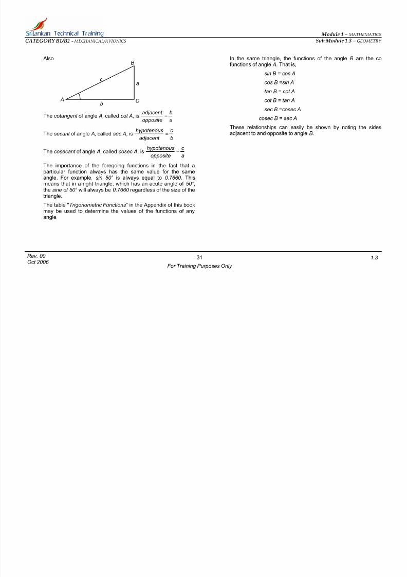
Also
The cotangent of angle A, called cot A, isa
b
opposite
adjacent =
The secant of angle A, called sec A, isb
c
adjacent
hypotenous=
The cosecant of angle A, called cosec A, isa
c
opposite
hypotenous=
The importance of the foregoing functions in the fact that aparticular function always has the same value for the sameangle. For example, sin 50° is always equal to 0.7660 . Thismeans that in a right triangle, which has an acute angle of 50°,the sine of 50° will always be 0.7660 regardless of the size of thetriangle.
The table "Trigonometric Functions" in the Appendix of this bookmay be used to determine the values of the functions of anyangle.
In the same triangle, the functions of the angle B are the cofunctions of angle A. That is,B
sin B = cos Ac
cos B =sin Aa
tan B = cot A
A cot B = tan AC b
sec B =cosec A
cosec B = sec A
These relationships can easily be shown by noting the sidesadjacent to and opposite to angle B.
31
For Training Purposes Only
Rev. 00 Oct 2006
1.3
7/27/2019 Module 1m.3 B1B2 Rev 00
http://slidepdf.com/reader/full/module-1m3-b1b2-rev-00 34/42
Module 1 – MATHEMATICS
Sub Module 1.3 – GEOMETRY CATEGORY B1/B2 – MECHANICAL/AVIONICS
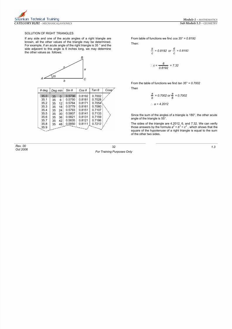
SOLUTION OF RIGHT TRIANGLES
If any side and one of the acute angles of a right triangle areknown, all the other values of the triangle may be determined.For example, if an acute angle of the right triangle is 35 ° and theside adjacent to this angle is 6 inches long, we may determinethe other values as follows:
From table of functions we find cos 35° = 0.8192
Then:
c
b= 0.8192 or
c
6 = 0.8192
B
∴ c =8192 .0
6 = 7.32
c a
35 ̊
A C b
From the table of functions we find tan 35° = 0.7002
ThenCoseTan θ θ deg. Sin θ Cos θ Deg min
b
a= 0.7002 or
6
a= 0.7002 2
84073
962
0.7000.7020.7050.7080.7100.713
0.7150.7180.721
∴ a = 4.2012
Since the sum of the angles of a triangle is 180°, the other acuteangle of the triangle is 55°.
The sides of the triangle are 4.2012, 6, and 7.32. We can verifythose answers by the formula a2 + b2 = c 2 , which shows that thesquare of the hypotenuse of a right triangle is equal to the sumof the other two sides.
0.81920.81810.81710.81610.81510.8141
0.81310.81210.8111
0.5730.5750.5760.5770.5790.580
0.5820.5830.585
604937
150
35.035.135.235.335.435.5
35.635.735.835.9
35 035 635 1235 1835 2435 30
35 3635 4235 48
32
For Training Purposes Only
Rev. 00 Oct 2006
1.3

7/27/2019 Module 1m.3 B1B2 Rev 00
http://slidepdf.com/reader/full/module-1m3-b1b2-rev-00 35/42
Module 1 – MATHEMATICS
Sub Module 1.3 – GEOMETRY CATEGORY B1/B2 – MECHANICAL/AVIONICS
If the sides of a right triangle are known, the angles can also bedetermined. This is shown in the problem below. In this triangle ABC , side a = 8, b = 15, and c = 17 .
Then sin A = 4706 .0 17
8
b
a==
From the table of functions
0.4706 = sin 28°4' (approximately)
Then angle A = 28 ° 4 ' ( approximately)
c==
A
CoseTan θ θ deg. Sin θ Cos θ Deg min
0.88460.88380.88290.88210.8813
0.88050.87960.87880.87800.8771
25792
4702
49506
1627
48 0.4660.4670.4690.4710.472
0.4740.4750.4770.478
27.827.928.028.128.2
28.328.428.528.628.7
0.5270.5290.5310.5330.536
0.5380.5400.5430.545
2727 5428 0028 0628 12
28 1828 2428 3028 3628
33
For Training Purposes Only
Rev. 00 Oct 2006
1.3

7/27/2019 Module 1m.3 B1B2 Rev 00
http://slidepdf.com/reader/full/module-1m3-b1b2-rev-00 36/42
Module 1 – MATHEMATICS
Sub Module 1.3 – GEOMETRY CATEGORY B1/B2 – MECHANICAL/AVIONICS
FUNCTIONS AS LINES
The functions of a right triangle can be represented by a single
straight line if we adopt a triangle with one side equal to unity. Byemploying a unit circle as shown in figure below, this method canbe demonstrated.
shown, diameters XX’ and YY’ are drawn with radiiIn the circleOY and OX and another radius, AO, all equal to 1. AB is thendrawn from the end of the radius OA and perpendicular to OX .OA is extended to E , where it intersects the tangent(perpendicular) drawn to OY. CX is drawn tangent to the circle atX and perpendicular to OX . There are now three similar triangles: ABO, CXO and OYE . The angle designated a is thesame in all three triangles. By arranging the functions so that the
denominator is always equal to 1, we can represent eachfunction by a single line. In the triangle ABO
sin a = )Hypotenous( AO
)opposite _Side( AB.
And AB = AO sin a
Since AO is equal to 1, the sine of angle a is AB. Continuing withthe same process and reasoning.
Cos a = AO
OB
OB = AO cos a
Since AO = 1 Cos a = OB.
Similarly..
Tan a =OX
CX = CX
Cot a =OY
EY = EY
Sec a = OX
OC = OC
Cosec a =OY
OE = OE
O X
Y
X’
Y’
A C
E a
a
B
34
For Training Purposes Only
Rev. 00 Oct 2006
1.3

7/27/2019 Module 1m.3 B1B2 Rev 00
http://slidepdf.com/reader/full/module-1m3-b1b2-rev-00 37/42
Module 1 – MATHEMATICS
Sub Module 1.3 – GEOMETRY CATEGORY B1/B2 – MECHANICAL/AVIONICS
CHANGES IN VALUES OF FUNCTIONS
If we study the unit circle shown in Figure below very carefully,we can visualize what will happen to each function as the anglea increases or decreases.
As angle a increases;
Sin a will increase to I.
Cos a will decrease to 0.
Tan a will increase to infinity (∞)
Cot a will decrease to 0.
Sec a will increase to infinity (∞)
Cosec a will decrease to 1
The values of the functions as the angle changes from 0° to 90°
are as follows.
sin a, 0 to 1
cos a, 1 to 0
tan a 0 to ∞
cot a,∞
to 0sec a, 1 to ∞
cosec a, ∞ to 1
O X
Y
X’
Y’
A C
E a
a
B
35
For Training Purposes Only
Rev. 00 Oct 2006
1.3

7/27/2019 Module 1m.3 B1B2 Rev 00
http://slidepdf.com/reader/full/module-1m3-b1b2-rev-00 38/42
Module 1 – MATHEMATICS
Sub Module 1.3 – GEOMETRY CATEGORY B1/B2 – MECHANICAL/AVIONICS
TRIGONOMETRICAL RELATIONSHIPS
The relations between functions and co functions have alreadybeen shown .However, certain relationships exist among all thefunctions, and these should be understood.
In the first discussion of functions, it was pointed out that
sin A =c
a and
cos A =.c
b
Thenb
a
b
c
c
a
c b
c a
A
A
Cos
Sin=×== = tan A
In a similar manner it can be shown that
sin A = tan A cos Acos A = sin A cot A
There are numerous other relationships which can be workedout and if it is desired and become thoroughly proficient in theuse of trigonometry, a substantial amount of study and practiceshould be given to this type of work.
FUNCTIONS OF PARTICULAR ANGLES
The angles 30°, 45° and 60° are particularly useful in thesolution of triangles. Hence, it is well to become familiar with thenumerical values of the functions of these angles. They aregiven on the following table:
ANGLE 30° 45° 60°
Sine
2 1
2 1
2
3
Cosine
2
3
2
1
2
1
Tangent
3
1
1 3
Co tangent 3 1
3
1
Secant
3
2 2 2
Co secant 2 2
3
2
A A
BC
c b
a
36
For Training Purposes Only
Rev. 00 Oct 2006
1.3

7/27/2019 Module 1m.3 B1B2 Rev 00
http://slidepdf.com/reader/full/module-1m3-b1b2-rev-00 39/42
Module 1 – MATHEMATICS
Sub Module 1.3 – GEOMETRY CATEGORY B1/B2 – MECHANICAL/AVIONICS
THE LAWS OF FUNCTIONS
LAW OF SINES
By appropriate proof it can be shown that in any triangle thesides, of the triangle are proportional to the sines of the oppositeangles. This is known, as the law of sines and is most useful insolving triangles other than right triangles.
The law of sines may be written
or B
A
Sin
Sin
b
a=
andC A
SinSin
c a =
andC
B
Sin
Sin
c
b=
THE LAW OF COSINES
The law of cosines is also useful in solving oblique trianglesand may be stated thus: The square of any side of a triangle isequal to the sum of the squares of the other two sidesdiminished by twice the product of the other two sides and thecosine of the included angle.
The law of cosines may also be written asBA2 = AC 2 + BC 2 – 2AC.BC.cos α
Or c 2 = a2 + b2 –2ab cos α
A
B C D a
bc
α
A
B C a
bc
a b c Sin A Sin B Sin C
= =
37
For Training Purposes Only
Rev. 00 Oct 2006
1.3

7/27/2019 Module 1m.3 B1B2 Rev 00
http://slidepdf.com/reader/full/module-1m3-b1b2-rev-00 40/42
Module 1 – MATHEMATICS
Sub Module 1.3 – GEOMETRY CATEGORY B1/B2 – MECHANICAL/AVIONICS
THE LAW OF TANGENTS
The law of tangents is derived from the law of sines and is statedthus: The difference between two sides of a triangle is to their sum as the tangent of half the difference between the oppositeangles is to the tangent of half their sum.
The law of tangents may be written
2 )B A(
2
ba +=
+
tan
FUNCTIONS OF ANGLES GREATER THAN 90 °
It is obvious that in Oblique triangles there will be times when thefunctions of angles greater than 90 ° are needed. The followingtable gives the method for determining function values for suchangles.
sin (90° + θ ) = cos θ
Cos (90° + θ ) = -sin θ
Tan(90° + θ ) = -cot θ
Cot (90° + θ ) = -tan θ
For simplicity in computation it is best to work with angles of lessthan 90°, and this is possible in most, cases.
)B A( tanba−
−
A
B C a
bc
90°θ
38
For Training Purposes Only
Rev. 00 Oct 2006
1.3
7/27/2019 Module 1m.3 B1B2 Rev 00
http://slidepdf.com/reader/full/module-1m3-b1b2-rev-00 41/42
Module 1 – MATHEMATICS
Sub Module 1.3 – GEOMETRY CATEGORY B1/B2 – MECHANICAL/AVIONICS
C OORDINATES
ular coordinates)ph is one of the most common ways of
presenting relationships and numerical information in graphicalsian coordinate graphs are extensively used in
mathematics to illustrate equations and mathematicalrelationships; and in science and engineering to plotexperimental results and to investigate the characteristics of such results.
A "conventional" graph is constructed by plotting pairs of relatedh paper and then drawing a
"smooth” curve through the plotted points. In mathematics it iscommon practice to use x and y as the symbols to denote twosets of related values. In introducing graphs we will use x and y,but we could-and indeed will use other symbols most relevant to
ur particular problem.
We already know how to mark a point on a graph and define itas we have already studied the method of graph plotting.
The system in which a point is located in a plane by specifyingits distance from two axes drawn at right angles (that is, the xand y-axes) is known as the Cartesian system of coordinates.The values of x and y defining a point are known as cartesiancoordinates.
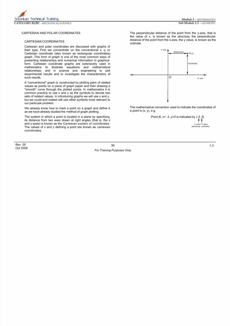
y-axis, that is; the perpendicular
The mathematical convention used to indicate the coordinates of a point
ARTESIAN AND POLAR C
CARTESIAN COORDINATES
Cartesian and polar coordinates are discussed with graphs of their type. First we concentrate on the conventional x -y or Cartesian coordinate (also known as rectanggraph. This form of gra
form. Carte
values as points on a piece of grap
o
The perpendicular distance of the point from thethe value of x, is known as the abscissadistance of the point from the x-axis, the y value, is known as theordinate.
Y- axis
O X- axis
P(x,y)
Y(ordinate)
X(abscissa)
is (x, y), e.g.
Point B, x= -3, y=5 is indicated by (-3, 5)
X value(abscissa)
Y value(ordinate)
39
For Training Purposes Only
Rev. 00 Oct 2006
1.3

7/27/2019 Module 1m.3 B1B2 Rev 00
http://slidepdf.com/reader/full/module-1m3-b1b2-rev-00 42/42
Module 1 – MATHEMATICS
Sub Module 1.3 – GEOMETRY CATEGORY B1/B2 – MECHANICAL/AVIONICS
The various areas into which the x and y aplane are known as quadrants
xes divide the graph
alues are negative, y values are positive
e (-, -)
by the radial distance r = OP from the origin O and the
polar diagrams. Such diagrams graphing
certain forms of data.
convention used to indicate the polar a
In the 1st quadrant x and y values are both positive (+, +)
In the 2nd quadrant x v( -, + )
In the 3rd quadrant x values and y values are both negativ
In the 4th quadrant x values are positive, y values are negative( + , -)
POLAR COORDINATES.
A second useful way of defining the position of a point is bymeans of polar coordinates, r and θ . The point P in figure belowis defined
angle θ =∡ POX , which is the angle the radial line makes with
the x-axis. Plots made using polar coordinates are known asare very useful in
The mathematical
O
Y
X
θ
r
P(r sin θ , r cos θ )
r sin θ
r cos θ
coordinates of point is (r sin θ , r cos θ ), e.g.
O
1
Y
st quadrant (+,+)
2 nd
quadrant (-,+)
3rd
quadrant (-,-)
4t
quadrant (+,-)
+ X -
-
+
If the radius akeswith x axis is 30°, then point B polar coordina
3 sin 30° and 3 cos 30°
(r) of a Point B, is 3 units and angle (θ ) it mtes are
40
For Training Purposes Only
Rev. 00 Oct 2006
1.3