CHAPTER 2 – Part 3 AM Modulation – Types of AM Methods (SSB and VSB)
Upload
muhammad-hammad-tariqCategory
view
55download
0description

SMARAD / Radio Laboratory 1
Modulation methods
S-72. 333 Physical layer methods in wirelesscommunication systems
Sylvain Ranvier / Radio Laboratory / TKK
16 November 2004

SMARAD / Radio Laboratory 2
Line out
1 Introduction
2 Principal Characteristics
2.1 Linear and Nonlinear Modulation Process
2.2 Analog and Digital Modulation Technique
2.3 Amplitude and Angle Modulation Processes
3 Linear Modulation Techniques
3.1 Binary Phase-Shift Keying
3.2 Quadriphase-Shift Keying
3.3 Offset Quadriphase-Shift Keying
3.4 π/4-Shifted Quadriphase-Shift Keying
4 Pulse Shaping
4.1 Root Raised-Cosine Pulse Shaping
5 Complex Representation of Linear modulated signals and Band-Pass Systems
6 Signal-Space Representation of Digitally Modulated Signals

SMARAD / Radio Laboratory 3
Line out cont.
7 Nonlinear Modulation Techniques
7.1 Frequency Modulation
7.2 Binary Frequency-Shifted Keying
7.3 Continuous-Phase Modulation: Minimum Shift Keying
7.4 Power Spectra of MSK Signal
7.5 Gaussian-Filtered MSK
8 Comparison of Modulation Strategies for Wireless Communications
8.1 Linear Channels
8.2 Nonlinear Channels
9 Performance: Bit Error Rate

SMARAD / Radio Laboratory 4
1 Introduction
Definition :
Process by which some characteristic of a carrier wave is varied in accordance with an information-bearing signal
Information-bearing signal → Modulating signal
Output of modulation process → Modulated signal
1 Introduction

SMARAD / Radio Laboratory 5
Three practical benefits from the use of modulation in wireless communication :
1) It is used to shift the spectral content of a message signal so that it lies inside the operating frequency band of the wireless communication channel
Ex.: telephonic communication over cellular radio channel Voice ≈ 300-3100Hz → freq. assigned to cellular radio channel ≈ 900-1800MHz
2) It provides a mechanism for putting the information content of a message signal into a form that be less vulnerable to noise or interference
Received signal ordinarily corrupted by noise → FM : improve system performance in presence of noise
3) It permits the use of multiple-access techniques
→ Simultaneous transmission of several different information-bearing signals over the same channel
1 Introduction

SMARAD / Radio Laboratory 6
2 Principal characteristics
2.1 Linear and Nonlinear Modulation Process
Linear Modulation :
→ Input-Output relation of modulator satisfies principle of superposition
• Output of modulator produced by a number of inputs applied simultaneously is equal to the sum of the output that result when the inputs are applied one at a time → M(i1+i2…+in) = M(i1)+M(i2)…+M(in)
• If the input is scale by a certain factor, the output of the modulator is scaled by exactly the same factor
2 Principal characteristics
Modulator
Input (modulating) signal m(t)
Sinusoidal carrier c(t)
Output (modulated) signal s(t)

SMARAD / Radio Laboratory 7
Nonlinear Modulation :
→ Input-Output relation of modulator does not (partially or fully) satisfies principle of superposition
Linearity and nonlinearity has importance in both theoretical and practicalaspects.
2 Principal characteristics

SMARAD / Radio Laboratory 8
2.2 Analog and Digital Modulation Techniques
Analog modulation :
Modulation of analog signal → infinity of value of the modulated parameter of the
modulated signal within a certain scale
Digital modulation :
Modulation of digital signal → finite number of value of the modulated parameter
of the modulated signal
Ex.: QPSK → 4 values of phase
2 Principal characteristics

SMARAD / Radio Laboratory 9
2.3 Amplitude and Angle Modulation Process
Carrier C(t) = Ac cos (2π fc t + θ )
Three parameters :
Ac → Amplitude modulation : AM
fc → Frequency modulation : FM
θ → Phase modulation : PM
1 Introduction

SMARAD / Radio Laboratory 10
3 Linear Modulation Techniques
3.1 Binary Phase-Shift Keying
Simplest form of digital phase modulation
Modulating signal = binary data stream =
Where P(t) = basic pulse and T = bit duration
bk = +1 for binary symbol 1
-1 for binary symbol 0
Binary symbol 0 → carrier phase θ(t) = 0 radians
Binary symbol 1 → carrier phase θ(t) = π radians
S(t) = Ac cos (2π fc t) for binary symbol 0
Ac cos (2π fc t +π ) for binary symbol 1
3 Linear Modulation Techniques
( ) ( )∑ −=k
k kTtpbtm

SMARAD / Radio Laboratory 11
As cos (θ (t) + π ) = − cos (θ (t))
S(t) = Ac cos (2π fc t) for binary symbol 0
- Ac cos (2π fc t +π ) for binary symbol 1
S(t) = c(t) m(t)
Inconvenient : transmission bandwidth = 2 x message bandwidth
3 Linear Modulation Techniques

SMARAD / Radio Laboratory 12
3.2 Quadriphase-Shift Keying (QPSK)
Interest : transmission bandwidth = message bandwidth
• Phase of carrier can take 4 different values depending on each dibit
• QPSK : Parallel combination of 2 BPSK modulators that operate inphase quadrature with respect to each other
3 Linear Modulation Techniques

SMARAD / Radio Laboratory 13
for i =1,2
Bk,i = +1 for binary symbol 0
-1 for binary symbol 1
For rectangular pulse : p(t) = +1 for 0 ≤ t ≤ 2T
0 otherwise
S(t) = s1 (t) + s2(t) = Ac m1(t) cos(2π fc t) + Ac m2(t) sin(2π fc t)
( ) ( )∑ −=k
iki kTtpbtm ,
3 Linear Modulation Techniques

SMARAD / Radio Laboratory 14
3.3 Offset Quadriphase-Shift Keying
Motivation :
QPSK : carrier phase may jump by ± 90° or ± 180° every 2 bit durations
Problem : filtering action can cause the carrier amplitude to fluctuate
→ receiver produce additional symbol errors
To reduce fluctuation → Offset Quadriphase-Shift Keying (staggered PSK)
Principle :
Second substream m2 (t) is
delayed (offset) by a bit duration T
phase transitions
are confined in 0°, ± 90°
3 Linear Modulation Techniques

SMARAD / Radio Laboratory 15
3.4 π/4-Shifted Quadriphase-Shift Keying
Motivation : similar to Offset Quadriphase-Shift Keying (OQPSK)
Carrier phase of QPSK can be (usually 1.) :
1. 0, π/2, π or 3π/2
2. π/4, 3π/4, 5π/4 or 7π/4
π/4-Shifted QPSK uses alternatively 1. And 2.
amplitude fluctuations during filtering are significantly reduced
• Reduced amplitude fluctuation becomes important when transmitterincludes slightly nonlinear amplifier
π/4-Shifted QPSK has been adopted in north American digital cellular time division multiple access (TDMA) standard IS-54 as well as the Japanese digital cellular standard
3 Linear Modulation Techniques

SMARAD / Radio Laboratory 16
Difference between conventional, offset and π/4-Shifted QPSK
3 Linear Modulation Techniques

SMARAD / Radio Laboratory 17
4 Pulse Shaping
Problems with rectangular pulse :
- Infinite spectrum → signal distortion when transmitted over band limited channel (wireless)
- Memory of wireless channel (multipath) → inter-symbol interference (ISI)
To overcome the 2 problems : pre-modulation filter Pulse shaping
use of fundamental theoretical work of Nyquist
Effects of ISI can be reduced to zero by shaping the overall frequency response P(f) so as to consist of a flat portion and sinusoidal roll-off portions
4 Pulse shaping

SMARAD / Radio Laboratory 18
For a given data rate R bits/sec : channel bandwidth may extend from minimum W = R/2 to adjustable value from
W to 2W
1/2W 0 ≤ | f | ≤ f1
P(f)= f1 ≤ | f | ≤ 2W - f1
0 | f | ≥ 2W - f1
roll-off factor : ρ = 1 – ( f1 / W ) = excess bandwidth over the ideal solution : ρ = 0
( )( )
−−+ ρρ
π1
2cos1
4
1Wf
WW
4 Pulse shaping

SMARAD / Radio Laboratory 19
4.1 Root Raised-Cosine Pulse Shaping
- Spectrum of basic pulse defined by square root of
0 ≤ | f | ≤ f1
P(f) = f1 ≤ | f | ≤ 2W - f1
0 | f | ≥ 2W - f1
When transmitter includes pre-modulation filter with this transfer function and
receiver include an identical filter :
overall pulse waveform will experience the spectrum P2(f) (regular raised cosine spectrum)
if channel affected by both flat fading and additive white noise :
Receiver maximize output signal-to-noise ratio
( )( )
−−+ ρρ
π1
2cos1
4
1Wf
WW
W2
1
( )( )
−− ρρ
π1
4cos
2
1Wf
WW
4 Pulse shaping
SMARAD / Radio Laboratory 20
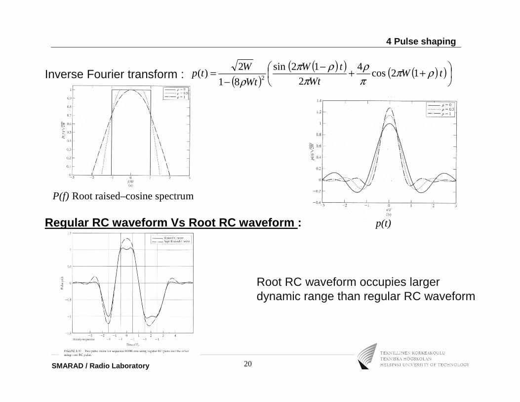
Inverse Fourier transform :
P(f) Root raised–cosine spectrum
Regular RC waveform Vs Root RC waveform : p(t)
( )( )( ) ( )( )
++−
−= tW
Wt
tW
Wt
Wtp ρπ
πρ
πρπ
ρ12cos
4
2
12sin
81
2)( 2
Root RC waveform occupies larger dynamic range than regular RC waveform
4 Pulse shaping

SMARAD / Radio Laboratory 21
5 Complex Representation of Linear modulated signals
Linear modulation scheme may be viewed as special case of canonical representation of a band-pass signal :
s(t) = sI(t) cos( 2π fc t ) – SQ(t) sin ( 2π fc t )
sI(t) : in-phase component of s(t)
sQ(t) : quadrature component of s(t)
5 Complex Representation of Linear modulated signals

SMARAD / Radio Laboratory 22
complex envelope of s(t) : and
Synthesizer for constructing modulated signal from in-phase and quadrature components : (a)
Analyzer for deriving the in-phase and quadrature components : (b)
5 Complex Representation of Linear modulated signals
( ) ( )tjststs QI +=)(~ ( ) ( ){ }tfjtsts cπ2exp)(~Re=

SMARAD / Radio Laboratory 23
6 Signal-Space Representation of Digitally Modulated Signals
Signal constellation (signal pattern) :
- Energy normalized version of in-phase component sI(t) = horizontal axis
0 ≤ t ≤ T
- Energy normalized version of quadrature component sQ(t) = vertical axis
0 ≤ t ≤ T
orthogonality of φ1 and φ2 over 0 ≤ t ≤ T
BPSK :
6 Signal-Space Representation of Digitally Modulated Signals
( )tfT cπφ 2cos2
1 =
( )tfT cπφ 2sin2
2 =
( ) ( ) 00
21 =∫ dtttT
φφ

SMARAD / Radio Laboratory 24
QPSK Other version of QPSK
6 Signal-Space Representation of Digitally Modulated Signals

SMARAD / Radio Laboratory 25
Quadrature Amplitude Modulation
Combination of amplitude modulation and phase modulation
Ex: 16-QAM
Remark:
Although QPSK can be transmitted over nonlinear channels,16-QAM need to be transmitted over linear channel
In QPSK energy transmitted remains fixed, although in 16-QAM energy transmitted is variable, depending on particular quad-bit
6 Signal-Space Representation of Digitally Modulated Signals

SMARAD / Radio Laboratory 26
7 Nonlinear Modulation Techniques
Preferably studied in polar form : s(t) = a(t) cos [2π fc t+θ (t)]
Where envelope =
and phase =
7.1 Frequency Modulation
f(t) = fc + kf m(t)
where kf = sensitivity of the frequency modulator
fc= frequency of un-modulated carrier
7 Nonlinear Modulation Techniques
)()()( 22 tststa QI +=
= −
)(
)(tan)( 1
ts
tst
I
Qθ

SMARAD / Radio Laboratory 27
Transmission bandwidth :
approximately given by Carson’s rule :
∆f = frequency deviation : maximum deviation in the instantaneous frequency
D = deviation ratio : ratio of the frequency deviation to the highest frequency component contained in the modulating signal
Unlike AM :
Increasing of FM transmission bandwidth produces quadratic increase in signal-to-noise ratio at the output of the receiver
Thanks to this bandwidth-noise trade-off capability : FM was adopted in first generation of wireless communication systems (based on FDMA)
7 Nonlinear Modulation Techniques
+∆≈
DfBT
112

SMARAD / Radio Laboratory 28
7.2 Binary Frequency-Shift Keying
Symbol 0 : sinusoid of frequency f1
Symbol 1 : sinusoid of frequency f2
i = 1, 2
T = symbol (bit) duration
Eb = energy transmitted per bit
nc = fixed integer and i = 1, 2 Sunde’s FSK
continuous-phase signal : phase continuity is maintained everywhere, including the inter-bit switching time
part of Continuous-Phase Frequency-Shifted Keying (CPFSK)
7 Nonlinear Modulation Techniques
Basic Encoding TechniquesBasic Encoding Techniques( ) ( )tf
T
Ets i
bi π2cos
2=
T
inf c
i
+=

SMARAD / Radio Laboratory 29
7.3 Continuous-Phase Frequency-Shifted Keying (CPFSK)
Goal : improve spectral efficiency and noise performance
Optimal parameters :
θ(T) - θ(0) = π h for symbol 1
- π h for symbol 0
7 Nonlinear Modulation Techniques
T
hff
T
hff cc 2
,2 21 −=+=
( ) ( ) ratiodeviationffThfffc =−=+= 2121 ,2
1
SMARAD / Radio Laboratory 30
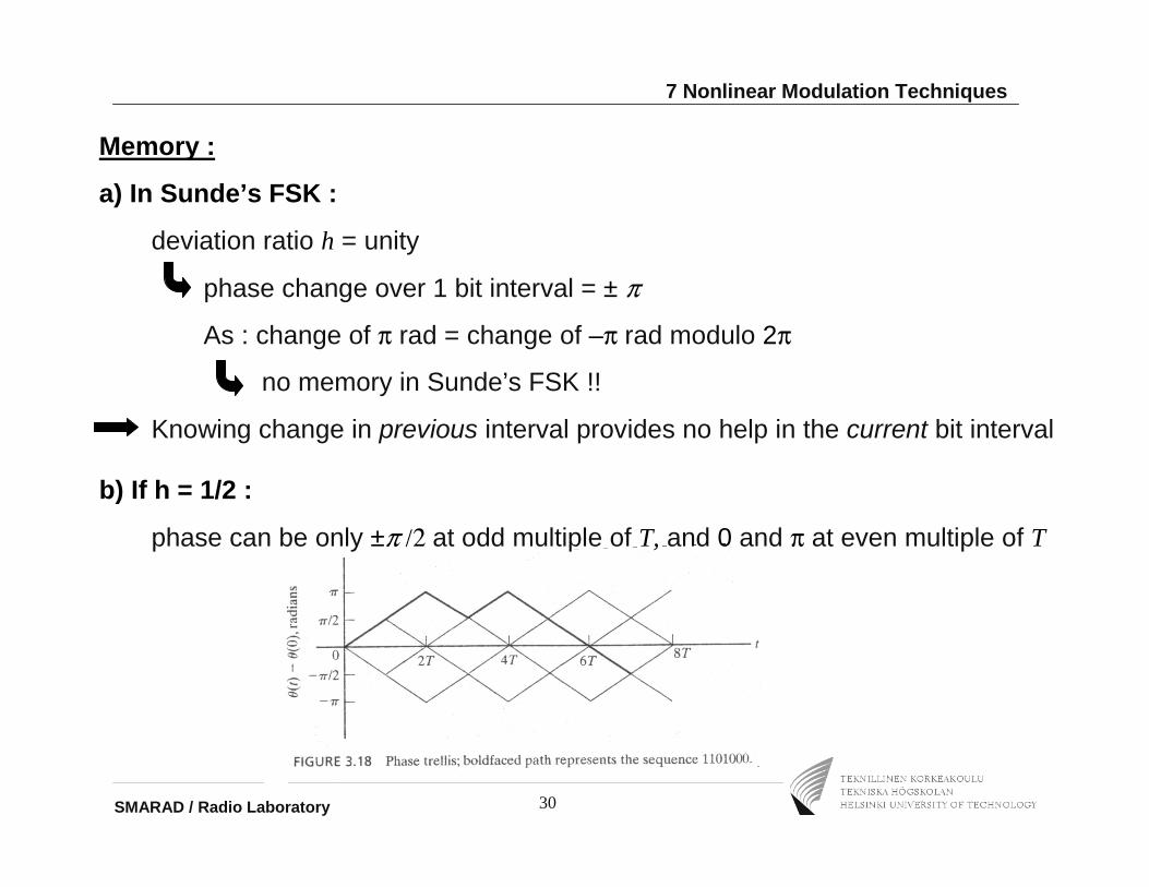
Memory :
a) In Sunde’s FSK :
deviation ratio h = unity
phase change over 1 bit interval = ± π
As : change of π rad = change of –π rad modulo 2π
no memory in Sunde’s FSK !!
Knowing change in previous interval provides no help in the current bit interval
7 Nonlinear Modulation Techniques
b) If h = 1/2 :
phase can be only ±π /2 at odd multiple of T, and 0 and π at even multiple of T

SMARAD / Radio Laboratory 31
If h = 1/2 :
Frequency deviation = ½ bit rate
minimum frequency spacing that allows FSK signals to be coherently orthogonal
(no interference during process of detection)
CPFSK signal with deviation ratio ½ is commonly referred as Minimum-Shift Keying (MSK)
7 Nonlinear Modulation Techniques

SMARAD / Radio Laboratory 32
7.4 Power spectra of MSK signal
In phase component = ± g1(t) with
quadrature component = ± g2(t) with
Base-band power spectral density =
base-band power spectral density decreases as the inverse fourth power of frequency (inverse square power of frequency for QPSK)
MSK does not produce as much interference outside signal band ofinterest as does QPSK
7 Nonlinear Modulation Techniques
( )
=
T
t
T
Etg b
I 2cos
2 π
( )
=
T
t
T
Etg b
Q 2sin
2 π
( ) 2
222 116
2cos32
−fT
TfEb ππ

SMARAD / Radio Laboratory 33
7.5 Gaussian-Filtered MSK
Motivation : Adjacent channel interference of MSK not low enough for multi-user communication environment
Goal : modify the power spectrum of the signal into a compact form
How : use of pre-modulation low-pass filter (base-band pulse shaping filter)
Polar non-return-to-zero (NRZ) binary data stream through base-band pulse-shaping filter with impulse response defined by a Gausssian function
response of Gaussian filter to rectangular pulse of unit amplitude and duration T :
W = 3dB base-band bandwidth
Parameter : time-bandwidth WT
7 Nonlinear Modulation Techniques
( ) ττππdtWWtg
T
T∫
−
−−=
2/
2/
222
2log
2exp
2log
2)(

SMARAD / Radio Laboratory 34
Power spectra of MSK and GMSK signals:
Curve for limiting condition WT = ∞ ordinary MSK
Undesirable feature of GMSK :
modulation signal no longer confined into a single bit interval
generation of controlled form of inter-symbol interference
(which increases with decreasing WT)
7 Nonlinear Modulation Techniques

SMARAD / Radio Laboratory 35
choice of WT offers trade-off between spectral compactness and reduction in receiver performance
Compromise value : WT = 0.3 ensures that side-lobes drop by at least 40dB
effects of side-lobes are negligible
Corresponding degradation in noise performance : 0.46dB
small price to pay for the desirable compactness of GMSK signal
Frequency shaping pulse truncated at t = ±2.5T and shifted in time by 2.5T :
7 Nonlinear Modulation Techniques

SMARAD / Radio Laboratory 36
8 Comparison of Modulation Strategies for Wireless Communications
Linear or Nonlinear channel ?
Depends if the transmit power amplifier is operated in its linear or nonlinear region
8.1 Linear channel
Criterion : transmit spectrum
- MSK as the inverse fourth power
- QPSK as the inverse square
QPSK with root Raised Cosine pulseshaping has narrowest main lobe and has negligible side lobes
8 Comparison of Modulation Strategies for Wireless Communications

SMARAD / Radio Laboratory 37
8.2 Nonlinear channel
Nonlinear effects depend upon envelope variation
No effect on rectangular QPSK, MSK and GMSK
Effects on QPSK with root RC filtering
(rely on its envelope variation to produce compact spectrum)
Phase distortion :
Depend on type of modulation :
- Can be tolerate in BPSK
- Should be very small for 64-QAM
8 Comparison of Modulation Strategies for Wireless Communications

SMARAD / Radio Laboratory 38
In practice :
Choice of modulation is a tradeoff between:
- transmit spectrum
- simplicity of detection
-error rate performance
QPSK with root raised-cosine filtering appears to be the method of choice
8 Comparison of Modulation Strategies for Wireless Communications

SMARAD / Radio Laboratory 39
9 Performance : Bit Error Rate
Performance of system measured in terms of average probability of symbol error
Bit Error Rate (BER)
9 Performance : Bit Error Rate

SMARAD / Radio Laboratory 40
For additive white Gaussian channel (AWG channel) :
Rayleigh fading process result in severe degradation
9 Performance : Bit Error Rate

SMARAD / Radio Laboratory 41
Homework
1) What is the problem of traditional QPSK ? How to overcome this problem ?
2) What is the interest of pulse shaping ?
3) How does Rayleigh fading channel affect the bit error rate when using BPSQ modulation, comparing with Gaussian noise channel ?
Homework