Modular construction
37
SteelConstruction.info The free encyclopedia for UK steel construction information Modular construction ‘Modular construction’ is a term used to describe the use of factory-produced pre-engineered building units that are delivered to site and assembled as large volumetric components or as substantial elements of a building. The modular units may form complete rooms, parts of rooms, or separate highly serviced units such as toilets or lifts. The collection of discrete modular units usually forms a self-supporting structure in its own right or, for tall buildings, may rely on an independent structural framework. Modular hospital building during installation of open sided modules (Image courtesy of Yorkon) The main sectors of application of modular construction are: Private housing Social housing Apartments and mixed use buildings Educational sector and student residences Key worker accommodation and sheltered housing Public sector buildings, such as prisons and MoD buildings Health sector buildings Hotels. Approximately 8000 modules are manufactured annually in the UK making it the biggest market in Europe. The largest markets for modular construction are in student residences, military accommodation and hotels, but the health sector is significant as it requires highly complex services and medical installations that can be commissioned and tested off-site. http://www.steelconstruction.info/Modular_construction - 31st October 2013 1 / 37
-
Upload
ehsan-golabzadeh -
Category
Documents
-
view
247 -
download
1
description
Â
Transcript of Modular construction

SteelConstruction.infoThe free encyclopedia for UK steel construction information
Modular construction‘Modular construction’ is a term used to describe the use of factory-produced pre-engineered building units that aredelivered to site and assembled as large volumetric components or as substantial elements of a building. Themodular units may form complete rooms, parts of rooms, or separate highly serviced units such as toilets or lifts.The collection of discrete modular units usually forms a self-supporting structure in its own right or, for tall buildings,may rely on an independent structural framework.
Modular hospital building during installation of open sided modules(Image courtesy of Yorkon)
The main sectors of application of modular construction are:
Private housing
Social housing
Apartments and mixed use buildings
Educational sector and student residences
Key worker accommodation and sheltered housing
Public sector buildings, such as prisons and MoD buildings
Health sector buildings
Hotels.
Approximately 8000 modules are manufactured annually in the UK making it the biggest market in Europe. Thelargest markets for modular construction are in student residences, military accommodation and hotels, but the health sector is significant as it requires highly complex services and medical installations that can becommissioned and tested off-site.
http://www.steelconstruction.info/Modular_construction - 31st October 2013
1 / 37

SteelConstruction.infoThe free encyclopedia for UK steel construction information
Attributes of modular construction
Modular units used in multi storey social housing project in London(Image courtesy of Yorkon)
The use of modular and other lightweight forms of building construction is increasing. The benefits of modularconstruction, relative to more traditional methods, include:
Economy of scale through repetitive manufacture
Rapid installation on site (6-8 units per day)
High level of quality control in factory production
Low selfweight leading to foundation savings
Suitable for projects with site constraints and where methods of working require more off-site manufacture
Limited disruption in the vicinity of the construction site
Useful in building renovation projects, such as roof top extensions
Excellent acoustic insulation due to double layer construction
Adaptable for future extensions, and ability to be dismantled easily and moved if required
Robustness can be achieved by attaching the units together at their corners
Stability of tall buildings can be provided by a braced steel core.
Modular construction is most commonly associated with cellular type buildings such as student residences or keyworker accommodation. For these applications it has the following features:
http://www.steelconstruction.info/Modular_construction - 31st October 2013
2 / 37
SteelConstruction.infoThe free encyclopedia for UK steel construction information
Suitable for buildings with multiple repeated units
Size of units is limited by transport (3.6m x 8m is typical)
Open sided units can be created (by changing the floor orientation)
Modules are stacked with usually no independent structure
Self weight of 1.5 to 2 kN/m2
4 to 10 storeys (6 is usually the optimum)
Fire resistance of 30 to 60 minutes provided
Acoustic insulation is provided through double layer walls and floors.
The following table describes the various structural elements used in walls and floors of modules.
http://www.steelconstruction.info/Modular_construction - 31st October 2013
3 / 37
SteelConstruction.infoThe free encyclopedia for UK steel construction information
Walls Floors
Walls of modules comprise C sections of 75 to 150 mm depth. Floors of modules comprise C sections of 150 to 250 mm depth.
Longitudinal walls are usually load-bearing and the end walls provide forstability.
Ceiling is manufactured as a wall panel.
Open-sided modules can be created by longitudinal floor and ceilingjoists – end walls become load bearing.
Open-sided modules use deeper floor joists or lattice joists of 250 to400 mm depth.
Stability provided by cross-flats or diaphragm action of boarding. Corridor zone can be used to provide in-plane bracing in long buildings.
Double skin walls provide excellent acoustic insulation. Double skin floor and ceiling provides excellent acoustic insulation.Mineral wool may be required between the joists.
Types of modules
The following types of modules may be used in the design of buildings using either fully modular construction ormixed forms of steel construction:
4-sided modules
Partially open-sided modules
Open-sided (corner-supported) modules
Modules supported by a primary structural frame
Non-load bearing modules
Mixed modules and planar floor cassettes
Special stair or lift modules.
The structure of the modules consists mainly of light steel C sections that are cold rolled from strip steel to BS EN10346[1]. Additional corner posts in the form of square hollow sections are often used.
4-sided modules
In this form of construction, modules are manufactured with four closed sides to create cellular type spacesdesigned to transfer the combined vertical load of the modules above and in-plane loads (due to wind action)through their longitudinal walls. The cellular space provided is limited by the transportation and installationrequirements. Depending on location and exposure to wind action, the height of buildings in fully modularconstruction is in the range of 6 to 10 storeys.
Modules are manufactured from a series of 2D panels, beginning with the floor cassette, to which the four wallpanels and ceiling panel are attached generally by screws. The walls transfer vertical loads and therefore thelongitudinal walls of the upper module are designed to sit on the walls of the module below.
Additional steel angles may be introduced in the recessed corners of the modules for lifting and for improved stability. Module to-module connections are usually in the form of plates that are bolted on site. Special liftingframes are used that allow the modules to be unhooked safely at height.
SteelConstruction.infoThe free encyclopedia for UK steel construction information
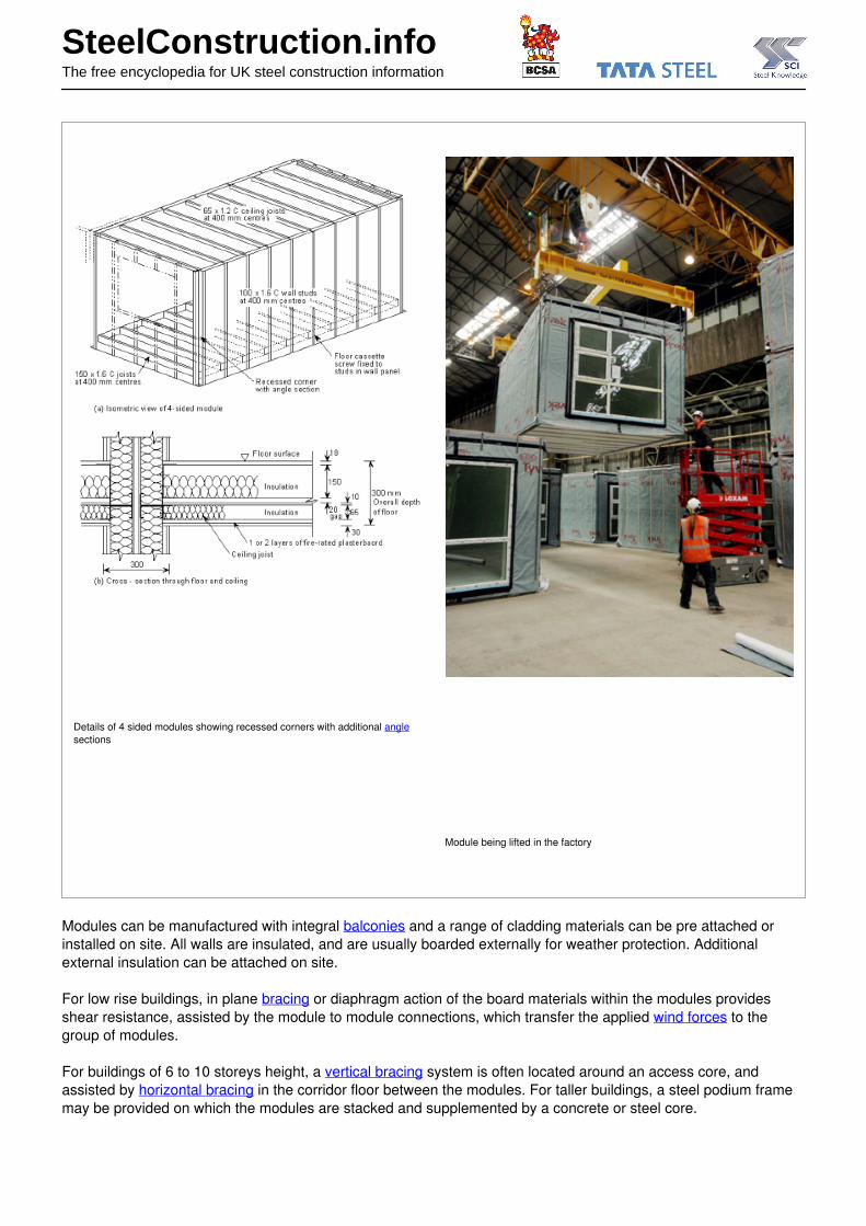
Details of 4 sided modules showing recessed corners with additional anglesections
Module being lifted in the factory
Modules can be manufactured with integral balconies and a range of cladding materials can be pre attached orinstalled on site. All walls are insulated, and are usually boarded externally for weather protection. Additionalexternal insulation can be attached on site.
For low rise buildings, in plane bracing or diaphragm action of the board materials within the modules providesshear resistance, assisted by the module to module connections, which transfer the applied wind forces to thegroup of modules.
For buildings of 6 to 10 storeys height, a vertical bracing system is often located around an access core, andassisted by horizontal bracing in the corridor floor between the modules. For taller buildings, a steel podium framemay be provided on which the modules are stacked and supplemented by a concrete or steel core.

SteelConstruction.infoThe free encyclopedia for UK steel construction information
The maximum height of a group of modules is dependent on the stability provided under wind action. Variouscases are presented in the table for scheme design (based on wind loading in the Midlands of England).

SteelConstruction.infoThe free encyclopedia for UK steel construction information
Form of modular construction Bracing requirements Limit on size in concept design
Typical max. number ofstoreys
Min. number ofmodules in a group
Single line of modules
No additional bracing 3 5
With additional bracing in gables 5 8
With additional stabilising core 7 No limit
Double line of modules with central
corridor
No additional bracing 6 2 x 8
With additional bracing in gables 8 2 x 10
With additional stabilising core 10 - 12 No limit
Partially open-sided modules
Layout of apartments using partially open sided modules – alternate modules are shaded(Image courtesy of PCKO Architects)
SteelConstruction.infoThe free encyclopedia for UK steel construction information
4 sided modules can be designed with partially open sides by introduction of corner and intermediate posts and byusing a stiff continuous edge beam in the floor cassette. The maximum width of opening is limited by the bendingresistance and stiffness of the edge member in the floor cassette. Additional intermediate posts are usually squarehollow sections (SHS), so that they can fit within the wall width.
Two modules can be placed together to create wider spaces. The compression resistance of the corner or internalposts controls the maximum height of the building, but 6 to 10 storeys can be achieved, as for fully modularconstruction.
Long modules can also be designed to include an integral corridor, as shown below. The length of the module maybe limited by transport and site access but a length of up to 12m is normally practical. Use of modules with integralcorridors can improve the speed of construction by avoiding weather tightness problems during installation andfinishing work.
SteelConstruction.infoThe free encyclopedia for UK steel construction information
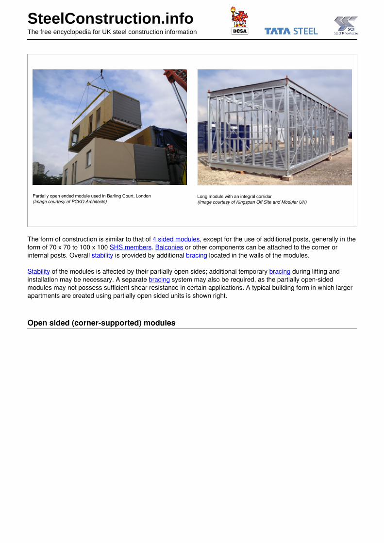
Partially open ended module used in Barling Court, London(Image courtesy of PCKO Architects)
Long module with an integral corridor(Image courtesy of Kingspan Off Site and Modular UK)
The form of construction is similar to that of 4 sided modules, except for the use of additional posts, generally in theform of 70 x 70 to 100 x 100 SHS members. Balconies or other components can be attached to the corner orinternal posts. Overall stability is provided by additional bracing located in the walls of the modules.
Stability of the modules is affected by their partially open sides; additional temporary bracing during lifting andinstallation may be necessary. A separate bracing system may also be required, as the partially open-sidedmodules may not possess sufficient shear resistance in certain applications. A typical building form in which largerapartments are created using partially open sided units is shown right.
Open sided (corner-supported) modules
SteelConstruction.infoThe free encyclopedia for UK steel construction information
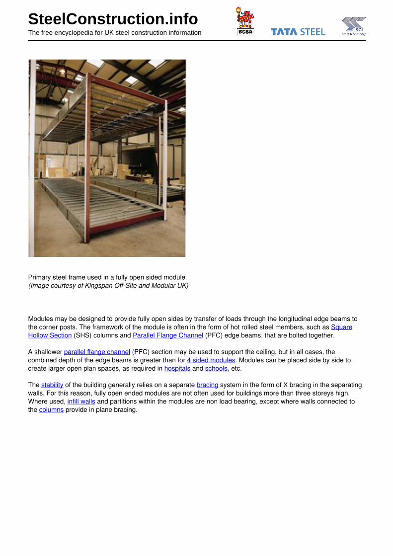
Primary steel frame used in a fully open sided module(Image courtesy of Kingspan Off-Site and Modular UK)
Modules may be designed to provide fully open sides by transfer of loads through the longitudinal edge beams tothe corner posts. The framework of the module is often in the form of hot rolled steel members, such as SquareHollow Section (SHS) columns and Parallel Flange Channel (PFC) edge beams, that are bolted together.
A shallower parallel flange channel (PFC) section may be used to support the ceiling, but in all cases, thecombined depth of the edge beams is greater than for 4 sided modules. Modules can be placed side by side tocreate larger open plan spaces, as required in hospitals and schools, etc.
The stability of the building generally relies on a separate bracing system in the form of X bracing in the separatingwalls. For this reason, fully open ended modules are not often used for buildings more than three storeys high.Where used, infill walls and partitions within the modules are non load bearing, except where walls connected tothe columns provide in plane bracing.
SteelConstruction.infoThe free encyclopedia for UK steel construction information
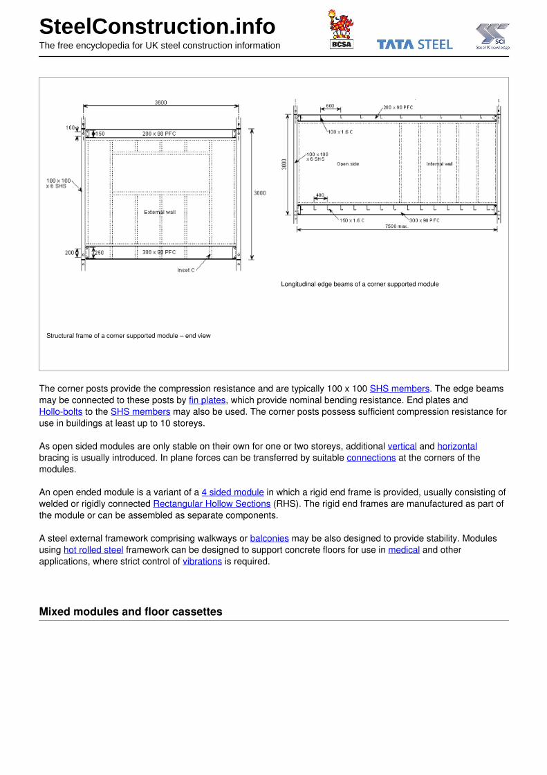
Structural frame of a corner supported module – end view
Longitudinal edge beams of a corner supported module
The corner posts provide the compression resistance and are typically 100 x 100 SHS members. The edge beamsmay be connected to these posts by fin plates, which provide nominal bending resistance. End plates and Hollo-bolts to the SHS members may also be used. The corner posts possess sufficient compression resistance foruse in buildings at least up to 10 storeys.
As open sided modules are only stable on their own for one or two storeys, additional vertical and horizontalbracing is usually introduced. In plane forces can be transferred by suitable connections at the corners of themodules.
An open ended module is a variant of a 4 sided module in which a rigid end frame is provided, usually consisting ofwelded or rigidly connected Rectangular Hollow Sections (RHS). The rigid end frames are manufactured as part ofthe module or can be assembled as separate components.
A steel external framework comprising walkways or balconies may be also designed to provide stability. Modulesusing hot rolled steel framework can be designed to support concrete floors for use in medical and otherapplications, where strict control of vibrations is required.
Mixed modules and floor cassettes

SteelConstruction.infoThe free encyclopedia for UK steel construction information
In this ‘hybrid’ or mixed form of construction, long modules may be stacked to form a load-bearing serviced coreand floor cassettes span between the modules and load-bearing walls. The modules are constructed in a similarway to that described for open-sided modules, but the loading applied to the side of the modules is significantlyhigher. Therefore, this mixed modular and panel form of construction is limited to buildings of 4 to 6 storey height. Itis typically used in residential buildings, particularly of terraced form, comprising modular ‘cores’ for stairs, andhighly serviced areas. The modules are arranged in a ‘spine’ through the building and the floors are attached to it.An example of this hybrid form of construction is shown.
SteelConstruction.infoThe free encyclopedia for UK steel construction information
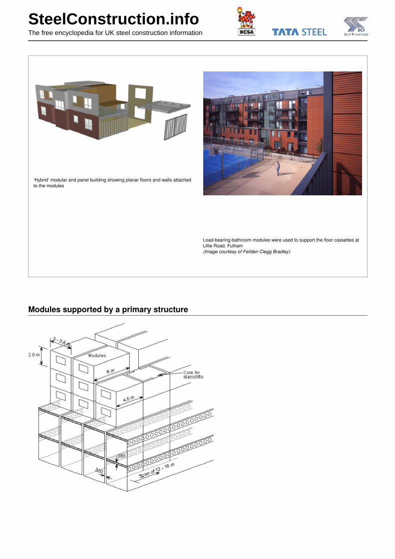
‘Hybrid’ modular and panel building showing planar floors and walls attachedto the modules
Load-bearing bathroom modules were used to support the floor cassettes atLillie Road, Fulham(Image courtesy of Feilden Clegg Bradley)
Modules supported by a primary structure

SteelConstruction.infoThe free encyclopedia for UK steel construction information
Modules supported by long spanning cellular beams to create open plan space at the lower levels
Modular units may be designed to be supported by a primary structure at a podium or platform level. In this case,the supporting columns are positioned at a multiple of the width of the modules (normally 2 or 3 modules). The beams are designed to support the combined loads from the modules above (normally a maximum of 4 6 storeys).
The supporting structure is designed conventionally as a steel framework with beams and columns that align withmultiples of the module width, and provides open plan space at ground floor and below ground levels. This form ofconstruction is very suitable for mixed retail, commercial and residential developments, especially for residentialunits above commercial areas or car parking, etc, particularly in urban projects.
Modules can be set back from the façade line. An example of a mixed development in Manchester is shown. Theground floor and below- ground car parking is a conventional composite structure.
Typical podium structure in which seven storeys of residential units are supported on a composite structure framebelow(Image courtesy of The Design Buro, Rollalong and Ayrshire Framing)
Where the 4 sided modules are designed to be supported by steel or composite beams and the typical line load persupported floor is 15kN/m, columns are placed at 6 to 8m spacing. A column spacing of 7.2m is suitable for belowground car parking. The depth of the podium type structure is 800 to 1000mm, and spans of 10 to 18m can becreated below the podium, which are suitable for commercial applications and car parking.
The podium structure is generally braced to resist wind loads and a separate braced core is often used to stabilisethe group of modules above the podium level. The module design is similar to that described for 4 sided modules. Wind loads can be transferred horizontally through the corridor floors.
Alternatively, non load bearing modules can be supported by a primary frame, and are installed as the constructionproceeds. Modules can be disassembled in the future to leave the floor cassette supported by the beams. Anexample of the mixed use of modules and primary steel frame is shown below left. The modules are shown shadedand floor spans indicated.
http://www.steelconstruction.info/Modular_construction - 31st October 2013
14 / 37

SteelConstruction.infoThe free encyclopedia for UK steel construction information
An external steel structure, consisting of a façade structure that acts to stabilise the building, may also be used.Modules are placed internally within the braced steel frame, as shown in the MoHo project in Manchester (belowright).

SteelConstruction.infoThe free encyclopedia for UK steel construction information
Mixed use of modules and long spanning floor with a primary steel frame
Installation of modules behind external steel framework at MoHo,Manchester(Image courtesy of Yorkon and Joule Consulting Engineers)
Other types of modules
Various forms of other modular components have been used in major building projects.
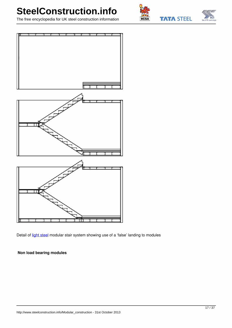
Stair module
Modular stairs may be designed as fully modular units and generally comprise landings and half landings with twoflights of stairs. The landings and half landings are supported by longitudinal walls with additional angles or SHSmembers to provide local strengthening, if necessary. The stair modules rely for their stability on a base and top,which leads to use of a false landing. The open top and base of the wall may be strengthened by a T, L or similarmembers to transfer out of plane loads to the landing. SHS posts and bracing can be introduced in the walls toprovide for overall stability.
SteelConstruction.infoThe free encyclopedia for UK steel construction information
Detail of light steel modular stair system showing use of a ‘false’ landing to modules
Non load bearing modules
http://www.steelconstruction.info/Modular_construction - 31st October 2013
17 / 37
SteelConstruction.infoThe free encyclopedia for UK steel construction information
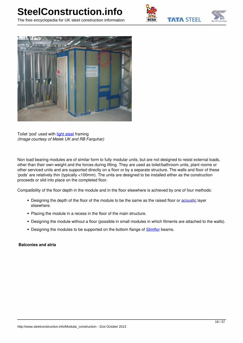
Toilet ‘pod’ used with light steel framing(Image courtesy of Metek UK and RB Farquhar)
Non load bearing modules are of similar form to fully modular units, but are not designed to resist external loads,other than their own weight and the forces during lifting. They are used as toilet/bathroom units, plant rooms orother serviced units and are supported directly on a floor or by a separate structure. The walls and floor of these‘pods’ are relatively thin (typically <100mm). The units are designed to be installed either as the constructionproceeds or slid into place on the completed floor.
Compatibility of the floor depth in the module and in the floor elsewhere is achieved by one of four methods:
Designing the depth of the floor of the module to be the same as the raised floor or acoustic layerelsewhere.
Placing the module in a recess in the floor of the main structure.
Designing the module without a floor (possible in small modules in which fitments are attached to the walls).
Designing the modules to be supported on the bottom flange of Slimflor beams.
Balconies and atria
http://www.steelconstruction.info/Modular_construction - 31st October 2013
18 / 37

SteelConstruction.infoThe free encyclopedia for UK steel construction information
Atrium created between modulesm(Image courtesy of Yorkon)
Balconies may be attached to modules in various ways:
Balconies supported by a self standing steel structure that is ground supported
Balconies attached between adjacent modules
Balconies that are attached to corner posts in the modules
Integrated balconies within an open sided module.
Atria may be created by attaching a lightweight steel roof to the upper modules or by by spanning the roof betweenthe modules as shown.
http://www.steelconstruction.info/Modular_construction - 31st October 2013
19 / 37

SteelConstruction.infoThe free encyclopedia for UK steel construction information
Balcony attachments to external structure (MoHo, Manchester)(Image courtesy of Shed KM Architects and Yorkon)
Key technical issues
The following general design issues are reviewed below:
Dimensional planning
Stability and structural integrity
Service interfaces
Acoustic performance
Fire safety.
Dimensional planning
The factors that influence the dimensional planning of modular systems in general building design may besummarised as:
Cladding requirements, including alignment with external dimensions of cladding
Planning grid for internal fit out, such as kitchens
Transportation requirements, including access to the site
Building form, as influenced by its functionality
Repeatability in modular manufacture.
Cladding
http://www.steelconstruction.info/Modular_construction - 31st October 2013
20 / 37

SteelConstruction.infoThe free encyclopedia for UK steel construction information
Brickwork design is based on a standard unit of 225mm width and 75mm depth. Therefore, it may be important todesign a floor depth to a multiple of 75mm in order to avoid non standard coursing of bricks.
Other types of cladding, such as clay tiles or metallic finishes, have their own dimensional requirements, butgenerally they can be designed and manufactured to fit with window dimensions etc. Many types of lightweightcladding can be pre attached to the modules, but it is generally necessary to install a cover piece over the jointsbetween the modules on site, to cater for geometrical tolerances and misalignments.
Standardisation of planning grid
Standardisation of the planning grid is important at the scheme design stage, as the planning grid will be controlledby other building components and fitments. A dimensional unit of 300mm may be adopted as standard for verticaland horizontal dimensions, reducing to 150mm as a second level for vertical dimensions. External walls aredetailed according to the type of cladding, but a 300mm total wall width may be adopted as a guide for mostcladding materials. The actual width will vary between 200mm for insulated render and board materials to 320mmfor brickwork.
Typical dimensions for planning in modular construction are presented in the table.
http://www.steelconstruction.info/Modular_construction - 31st October 2013
21 / 37

SteelConstruction.infoThe free encyclopedia for UK steel construction information
Typical dimensions for planning in modular construction
Application Internal wall height(mm)
Internal modulewidth (mm)
Internal modulelength (m)
Ceiling-floor zone(typical) (mm)
Study bedrooms 2400 2500 – 2700 5.4 to 6 300
Apartments 2400 3300 – 3600 6 to 9 450
Hotels 2400 – 2700 3300 – 3600 5.4 to 7.5 450
Schools 2700 – 3000 3000 – 3600open-sided
9 to 12 600
Offices 2700 – 3000 3000 – 3600 6 to 12 600 – 750
Health sector 2700 – 3000 3000 – 3600open-sided
9 to 12 600 – 750
Typical wall and floor/ceiling dimensions
Transportation
Guidance on transportation on major roads is given by the Road Haulage Association, based on the Road Vehicles(Construction and Use) Regulations[2].
The following basic requirements for transportation should be considered when designing the sizes of modularunits:
Modules exceeding 2.9m external width require 2 days notice to the police
Modules exceeding 3.5m width require a driver’s mate and 2 days police notice
Modules exceeding 4.3m width require additional speed restrictions and may require police escort.

SteelConstruction.infoThe free encyclopedia for UK steel construction information
Stricter limits may be required for local roads, particularly in urban areas. In all cases, the maximum height of theload is 4.95m for motorway bridges. Standard container vehicles can deliver one large or two smaller units.
Internal walls
Internal walls comprising the walls of adjacent modules may be designed for a standard 300mm face face overallwidth, incorporating the sheathing boards, internal plasterboards and insulation between the C sections. The gapbetween the walls is a variable, depending on the number and thickness of boards and size of the wall studs.
Floor zone
Floors and ceilings in modular construction are deeper than in more traditional construction. The three structuralcases of side supported (4-sided modules), corner supported (open sided) and frame supported modules requiredifferent overall ceiling floor dimensions for planning purposes, as follows:
Continuously supported or 4-sided modules: 300 or 450mm
Corner supported or open-sided modules: 450 to 600mm
Frame supported modules: 750 to 900mm.
In most cases, 450mm may be adopted as a standard for the floor-to-ceiling dimension, although many systemsprovide shallower depths. For corner supported modules, a standard overall floor and ceiling depth of 600mm maybe used. The gap between the floor and ceiling is a variable depending on the number of boards and the joist size.
Detail of corner supported module
Stability and structural integrity
http://www.steelconstruction.info/Modular_construction - 31st October 2013
23 / 37

SteelConstruction.infoThe free encyclopedia for UK steel construction information
Tying forces in modular construction subject to loss of one module by fire or explosion
Overall stability is provided by the modules themselves, or by an external structure. The load path is through thewalls of the 3-D units, and so removal of this load path means that the walls should be designed to either:
Span horizontally over the damaged area by acting as a deep beam ,or
Be supported by tie forces to the adjacent units.
The latter means that the units should be tied both horizontally and vertically. Robustness is provided by the tiesbetween the modules with a normally assumed minimum tying force equivalent to half the loaded weight of themodule (minimum value of 30kN).
Service interfaces
http://www.steelconstruction.info/Modular_construction - 31st October 2013
24 / 37

SteelConstruction.infoThe free encyclopedia for UK steel construction information
The installation of electrical, plumbing and heating services in modular buildings can be largely carried out in thefactory with final connections made on-site. In traditional construction, such activities are labour intensive on-siteand are often on the critical path, so that any difficulties can cause delays. Service strategies that have been usedin modular buildings include:
Use of communal spaces for distribution of services
Use of the floor or ceiling zone within each module for service distribution
Installation of services within each module in the factory with site work involving only connection of modules
Drainage connections of modules connected to vertical risers in the corner of the modules
Wet areas are connected back to back to concentrate service zones.
A vertical service duct is usually incorporated in the corner of each unit to accommodate the vertical drainage andpipework. The services in each module are installed in the factory and terminate in the vertical duct. Access to theservice duct is generally only possible from circulation areas outside the modular unit.
The horizontal distribution of services between modules varies, depending on the building type. For most types of residential buildings and hotels, the corridor ceiling and floor voids act as service zones.
Vertical drainage stacks are also installed in the factory and a removable floor panel is provided to allow the finalconnection to the drains installed in the ground on-site. This requires a high degree of accuracy in setting outservice inlets on-site.
http://www.steelconstruction.info/Modular_construction - 31st October 2013
25 / 37
SteelConstruction.infoThe free encyclopedia for UK steel construction information
Typical service duct in a modular hotel building
Acoustic performance
Modular construction provides a high level of acoustic separation because each module has separate floor, ceilingand wall elements, which prevents direct transfer of sound along the members.
Modular unit manufacturers use various methods to further improve sound reduction between units – twooverlapping layers of plasterboard fixed inside each module, oriented strand board (OSB) or plasterboard fixed asexternal sheeting or quilt insulation between steel members.
Special care needs to be taken around openings for service pipes or other penetrations, because soundattenuation is particularly affected by air pathways between spaces. Electrical sockets penetrate the plasterboardlayer, so they should be carefully insulated using quilt at their rear.
Fire safety
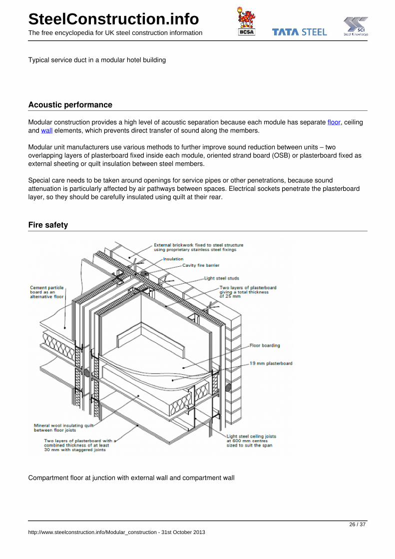
Compartment floor at junction with external wall and compartment wall
http://www.steelconstruction.info/Modular_construction - 31st October 2013
26 / 37
SteelConstruction.infoThe free encyclopedia for UK steel construction information
Fire safety is related to provision of adequate means of escape, to ensuring structural integrity, and controllingspread of fire across compartment boundaries. Minimum periods of fire resistance are given in for England & Walesin Approved Document B[3].
Modular construction generally achieves these requirements by the use of fire resistant plasterboard conforming toBS EN 520[4], Type F. Alternative materials, such as cement particle board and gypsum fibre board may also beused in combination with plasterboard as the facing layer.
Each module is lined internally with one or two layers of fire resistant plasterboard as follows:
For walls: 30 minutes fire resistance is achieved by a single layer of 12.5mm fire resistant plasterboard oneach face of a steel stud wall
For walls: 60 minutes fire resistance is achieved by one layer of 12.5mm fire resistant plasterboard on alayer of 12.5 mm wallboard with staggered joints on each face of a steel stud wall
For floors: 30 minutes fire resistance is achieved with 18mm tongue and groove boarding on light steeljoists and 12.5mm fire resistant plasterboard beneath with joints taped and filled
For floors: 60 minutes fire resistance is achieved with at least 18mm T&G board floor finish and one layer of12.5mm fire resistant plasterboard on a layer of 12.5mm wallboard with staggered joints beneath the steeljoists.
In residential construction, each dwelling usually forms a separate fire compartment. All walls and floors thatprovide a separating function between compartments require 60 minutes fire resistance. In hotels and other residential buildings, each bedroom may form its own compartment.
In general, a compartment floor will also act as a separating floor for acoustic purposes, as the same measures willalso achieve excellent acoustic insulation between rooms.
The inherent separation between modules provides an effective barrier to spread of fire. Means of escape shouldbe considered early in the scheme design in order to ensure that the module design and layout can satisfy theserequirements. Cavity barriers are required within the cavity in the external wall between the module and thecladding at intersections with compartment walls. They are also required horizontally at junctions with floors androof, and vertically at a maximum lateral spacing of 20m (or 10m where the material exposed to the cavity is notClass 0 or 1 as defined by Approved Document B[3]. ). Fire stops must be provided around any penetrationsthrough fire resisting walls.
Sustainability
The concept of using Sustainability indicators is becoming accepted as part of the environmental assessment ofbuilding construction. For modular construction, it is appropriate to include whole life measures, such as potential re-use, or re-location which are not properly reflected in conventional measures of sustainability.
The Sustainability indicators relevant to modular construction are listed below. Comments on how modularconstruction contributes to these indicators are given against each indicator.
http://www.steelconstruction.info/Modular_construction - 31st October 2013
27 / 37

SteelConstruction.infoThe free encyclopedia for UK steel construction information
Energy efficiency
Sustainability indicator Comment on modular construction
Minimise energy in use Good level of thermal insulation
Efficient heating and cooling systems
Control systems for energy saving provided
Energy saving measures Efficient manufacture
Minimise CO2 production from fossil fuels Efficient operation and thermal insulation
Efficient use of materials
Minimise embodied energy in materials Factory controlled operation
100% recyclable
High strength to weight ratio
Ease of deconstruction and re-use
SteelConstruction.infoThe free encyclopedia for UK steel construction information
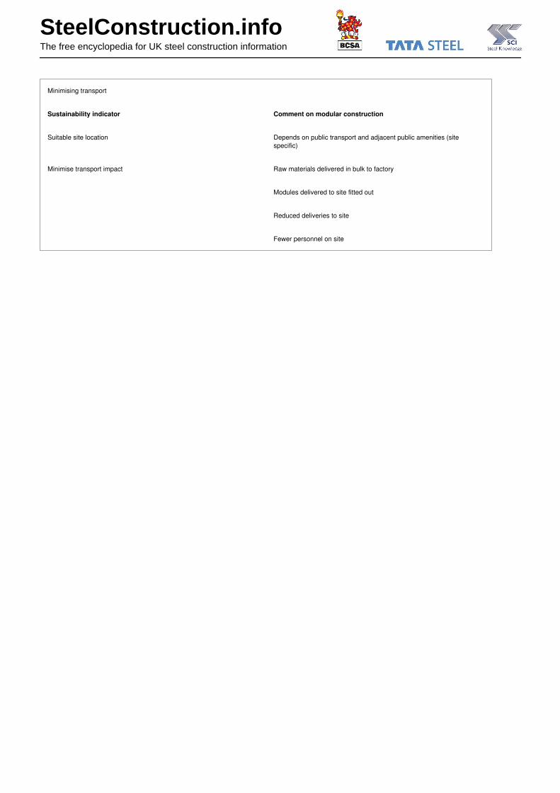
Minimising transport
Sustainability indicator Comment on modular construction
Suitable site location Depends on public transport and adjacent public amenities (sitespecific)
Minimise transport impact Raw materials delivered in bulk to factory
Modules delivered to site fitted out
Reduced deliveries to site
Fewer personnel on site

SteelConstruction.infoThe free encyclopedia for UK steel construction information
Minimising pollution
Sustainability indicator Comment on modular construction
No use of ozone-depleting substances Insulation materials selected to suit client needs
Minimise waste creation and disposal Efficient use of materials in factory
Minimum / zero waste on site
Recycling of scrap metal
Re-use of modules or components
Maximise waste recycling ratio Recycled steel used in manufacture
Modules can be re-used
Minimise nuisance in construction Noise, vibration and dust reduced
Fast construction process
Less waste disposal
Fewer site deliveries

SteelConstruction.infoThe free encyclopedia for UK steel construction information
Efficient materials and resource use
Sustainability indicator Comment on modular construction
Efficient use of materials Steel has high strength to weight ratio
Efficient design in materials use
Long design life
Proportion of recycled to primary materials / components Recycled steel used in manufacture of framework of modules
Ability to be recycled or re-used High proportion can be recycled
Modules can be re-used
Low maintenance Few ‘call backs’ due to quality of production
Accessibility for maintenance is easier
Provision for future adaptability Ability to extend / modify building
SteelConstruction.infoThe free encyclopedia for UK steel construction information
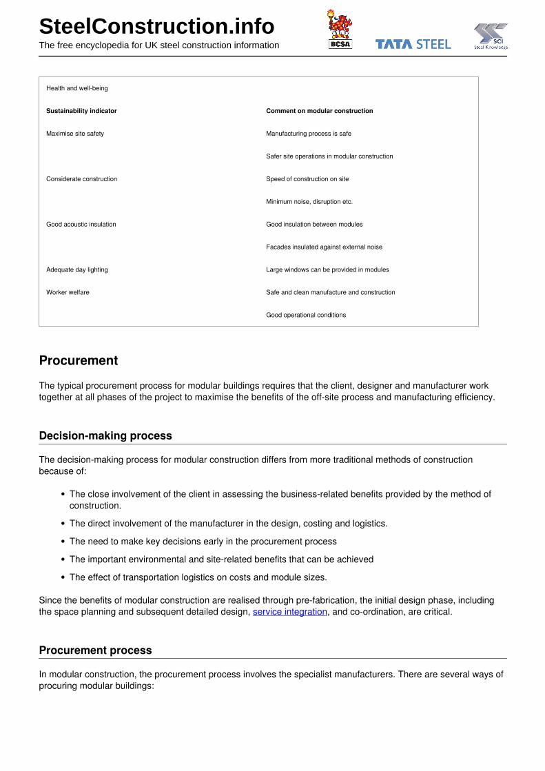
Health and well-being
Sustainability indicator Comment on modular construction
Maximise site safety Manufacturing process is safe
Safer site operations in modular construction
Considerate construction Speed of construction on site
Minimum noise, disruption etc.
Good acoustic insulation Good insulation between modules
Facades insulated against external noise
Adequate day lighting Large windows can be provided in modules
Worker welfare Safe and clean manufacture and construction
Good operational conditions
Procurement
The typical procurement process for modular buildings requires that the client, designer and manufacturer worktogether at all phases of the project to maximise the benefits of the off-site process and manufacturing efficiency.
Decision-making process
The decision-making process for modular construction differs from more traditional methods of constructionbecause of:
The close involvement of the client in assessing the business-related benefits provided by the method ofconstruction.
The direct involvement of the manufacturer in the design, costing and logistics.
The need to make key decisions early in the procurement process
The important environmental and site-related benefits that can be achieved
The effect of transportation logistics on costs and module sizes.
Since the benefits of modular construction are realised through pre-fabrication, the initial design phase, includingthe space planning and subsequent detailed design, service integration, and co-ordination, are critical.
Procurement process
In modular construction, the procurement process involves the specialist manufacturers. There are several ways ofprocuring modular buildings:
SteelConstruction.infoThe free encyclopedia for UK steel construction information
Traditional, in which an architect provides the design co-ordination and the general contractor provides theconstruction co-ordination. The module manufacturer acts as a specialist sub-contractor.
'Design and Build’ process, in which the module manufacturer provides the detailed design and constructionresponsibilities. In this case, the client’s architect may carry out some of the outline design, and may benovated by the client to work for the contractor.
A Design and Build contract is often used for modular construction. In such cases, the role of the client’s architectwill depend on the particular procurement process. Two methods of specification by the architect are mostcommonly used:
The architect may specify the manufacturer who will undertake the detailed design work. This will enablethe parties to work together from inception to completion.
Alternatively, the architect may draft a performance specification for the work. This is then used as a basisfor tendering, either through a main contractor or directly to the modular specialists.
It should be recognised that each manufacturer undertakes the construction of their modular units differently andthey will be prepared to offer advice and provide drawings at the concept stage.
Importantly, the ‘lead-in’ time required for prototype, design and manufacture of bespoke module units should beconsidered, although detailed design of the modular units can be carried out in parallel with other design activities.If the module configuration is repeated from other projects, then design time is much reduced.
Typical details
Connections
Guidance on the design and detailing of the most common connection types is given in BS EN 1993-1-8[5].Manufacturers use the method which best suits their manufacturing process and for which appropriate test data areavailable.
Structural connections between modules are required for integrity and robustness but details vary depending onthe form of the module and the particular application. Floor boarding, plasterboard and sheathing boards areattached using self drilling, self-tapping screws. Manufacturers of light steel framed modules have prepared theirown details of horizontal attachments that satisfy robustness requirements.
Attachment points
Attachments between modules are made in both horizontal and vertical directions, primarily to transfer in planeforces, but also for structured integrity.
http://www.steelconstruction.info/Modular_construction - 31st October 2013
33 / 37

SteelConstruction.infoThe free encyclopedia for UK steel construction information
Corner posts using hot rolled steel angles
SHS provide the highest compressive resistance and may be used as the corner posts for open sided modules.However, although these sections are compact, their connections can be more complex. A welded fin plate towhich the edge beams are bolted is shown. Access holes in the SHS allow bolts to be inserted through end platesto provide for vertical and horizontal attachments.
Corner post using SHS or special sections
http://www.steelconstruction.info/Modular_construction - 31st October 2013
34 / 37

SteelConstruction.infoThe free encyclopedia for UK steel construction information
Facades and interfaces
Various interfaces between modular units and other components in the building may not be under the control of themodular manufacturer. The responsibility for design and coordination usually lies with the building designer.
Foundation interfaces
A variety of foundations can be used, including strip, trench-fill, pad and piled foundations. Further information onpile foundations is given in SCI P299. Strip or trench-fill foundations are most common.
Modular units are lightweight and therefore foundations may be smaller than in traditional construction.Nevertheless, the cladding options and building height may dictate the foundation design. With strips, rafts orground beams, the modular units can be designed to be continuously supported around the perimeter of each unit.
Typical trench-fill foundation detail for masonry cladding
The levelling of the foundations or ground beams is crucial to the subsequent installation and alignment of themodular units. The modular manufacturers have developed their own proprietary locating and fixing mechanisms toaid the positioning of units on the foundations
Wall cladding interfaces
http://www.steelconstruction.info/Modular_construction - 31st October 2013
35 / 37

SteelConstruction.infoThe free encyclopedia for UK steel construction information
Claddings for modular buildings can be self supporting vertically and only supported laterally by the units.Alternatively, they can be supported entirely by the modular structure.
Two generic systems of facade construction may be considered:
Cladding that is placed entirely on-site using conventional techniques.
Cladding that is completely or partially attached in the factory; infill pieces or secondary cladding may befixed on-site.
Cavity barriers must also be incorporated into any cavity that occurs between the external cladding and themodular structure. These must resist the spread of smoke and flame and are required between all separatedwellings or fire compartments. Mineral wool is generally used.
Roofing interfaces
Roofing materials for modular buildings generally comprise tiles supported on battens, or roof sheeting on purlins.Modern roofs may comprise tiles supported on roof sheeting or structural liner trays. Flat roofs can also beconstructed with a variety of weatherproof finishes. Insulation in the line of the roof pitch is used where a ‘warmroof’ is created. However, in most cases, the roof space is ‘cold’, and insulation is placed directly on the uppersurface of the modular units.
Roofs are generally designed as separate structures that are supported either continuously by the internal walls ofthe modular units, or as free spanning roofs between the outer walls. Roofs may also be designed as modular unitsfor habitable space, and ease of installation, especially in taller buildings. However, conventional trussed rafter orpurlin roofs are mostly used.
Roofs are designed to support the weight of the roof covering, snow loads, services and tanks stored on the roofspace, and occupancy loads from habitable use. The interface between the roof and the modular units is designedto resist both compression and tension due to wind uplift. In some cases, the roof can be designed to bedetachable so that the building can be extended later. Shallow pitch roofs can be designed to be supported directly
http://www.steelconstruction.info/Modular_construction - 31st October 2013
36 / 37
SteelConstruction.infoThe free encyclopedia for UK steel construction information
by the modular units and are easily dismantled.
References
1. ^ BS EN 10346:2009 Continuously hot-dip coated steel flat products. Technical delivery conditions. BSI
2. ^ Road Vehicles (Construction and Use) Regulations, TSO, 1986 (amended 2011)
3. ^ 3.03.1Approved Document B,(Fire Safety) 2006. Department of Communities and Local Government
4. ^ BS EN 520:2004+A1:2009 Gypsum plasterboards. Definitions, requirements and test methods. BSI
5. ^ BS EN 1993-1-8:2005 Eurocode 3. Design of steel structures. Design of joints. BSI
Resources
SCI P129 Building design using cold formed steel sections: Fire protection
SCI P299 Mini-Piles and Composite Ground Floors for Housing
SCI P302 Modular Construction using Light Steel Framing. Design of Residential Buildings
SCI P272 Modular Construction using Light Steel Framing. An Architect’s Guide
SCI P284 Modular Construction in Building Extensions
SCI P348 Building Design Using Modules
SCI P367 Energy efficient housing using light steel framing.
See also
Infill walling
Residential/Mixed-use Buildings
Education buildings
Healthcare buildings
Robustness
Acoustics
Sustainability
External links
Yorkon
Terrapin
Powered by TCPDF (www.tcpdf.org)
http://www.steelconstruction.info/Modular_construction - 31st October 2013
37 / 37