Models, tasks, RT operating systems and schedulability
102
Models, tasks, RT operating systems and schedulability Marco Di Natale Associate Professor, Scuola S. Anna - Italy, UTRC Visiting Fellow
Transcript of Models, tasks, RT operating systems and schedulability

Models, tasks, RT operating systems and
schedulability
Marco Di NataleAssociate Professor, Scuola S. Anna - Italy, UTRC Visiting Fellow

A development cycle

Model-based design
On August 19, 1418, a competition was announced in Florence, where the city’s
magnificent new cathedral, Santa Maria del Fiore, had been under constructionfor more than a century
Whoever desires to make any model or design for the vaulting of the main Dome of the Cathedral under construction by the Opera del Duomo-for armature, scaffolding or other thing, or any lifting devicepertaining to the construction and perfection of said cupola or vaultshall do so before the end of the month of September. If the model be used he shall be entitled to a payment of 200 gold Florins.

Model-based design
Engineering has made use of models since its very early days
Engineering has made use of models since its very early days
Filippo Brunelleschi's design for the dome of the cathedral
of Santa Maria del Fiore in Florence remains one of the
most towering achievements of Renaissance architecture.
Completed in 1436, the dome remains a remarkable feat of
design and engineering. Its span of more than 140 feet
exceeds St Paul's in London and St Peter's in Rome, and
even outdoes the Capitol in Washington, D.C., making it the
largest dome ever constructed using bricks and mortar.
When work on the dome began in 1420 Brunelleschi was
virtually unknown. Sixteen years later the dome was built,
and its architect was a superstar.

Model-based design flow
• Typical flow, updated in
V-shape or iterative
fashion or V-shape
plus iterative ….
• The four tenets on the
right are fundamental
to model-based design
• Of course, you must
select a modeling
language that allows to
do everything in the
most natural and easy
way …

• Design (continued): matching the logical design into the SW architecture design
Dispenser
«boundary»Valve
status
open
close
«boundary»Holster Switch
status
«boundary»Flowmeter
count
«boundary»Motor
status
stop
start
«auxiliary» {semantics = controls EH Unit}EH Unit
active
EH id
nozzle removed
dispensing authorised
halt
resume
fuel pulse
nozzle replaced
«focus»Dispenser
dispenser number
transaction fuel price
active EH id
fuel_grade
abort
get transaction details
halt
get fuel price
request service
dispensing authorised
resume
dispensing completed
«boundary»Dispenser Display
perform display check
freeze display
update display
«entity» {persistence = transitory}Fuel Transaction
litres dispensed
price per litre
total cost
create
collect details
destroy
add 5ml
«entity» {persistence = persistent}Fuel Observer
price per litre
grade
set price
get price
Kiosk
«entity» {persistence = persistent}Fuel
price per litre
grade
set price
get price
«boundary»EPOS
process transaction
Kiosk Controller
fuel price
fuel amount
fuel grade
transaction amount
select grade
new price information
payment due
dispensing authorized
display fuel price
request service
halt dispensing
resume dispensing
select dispenser
abort transaction
collect transaction
«boundary»Keyboard Unit
«boundary»Kiosk Display
display transaction details
display dispenser idle
display dispensing authorised
dispensing suspended
display service request
display payment due
display fuel price
clear
Fuel Change Manager
notify
1
1
fuel type available at
3
1
gets price fromtheObserver
1
1
myMotor
1
3
updated by
fuelPrice
3 1
myDispensermyEHUnits
0..1 1active
theDispenseractiveEH
1
1
sends trans. details to
theEPOS
1
1myEH
mySwitch
1
1
myMeter
0..1 1
1
1
dDisplay
11..16 controlled by
aDispenser theKiosk
1 1
myController
1
1
theDisplay
2 1
myValves
11..16
updated by
1
1
notifies
theManagerthePrice
This Class Diagram is an early, pre-task design view of class relationships, based on the Object design interaction models.
This diagram would be considerably enhanced as further implementation detail was added.
the 'active' EH Unit is one of the
aggregate EH Units of the Dispenser
RTOS
Threads (tasks)Threads (tasks)Resources
RTOS API
Task and resource
model
Timing attributes (fromplatform deployment)
Timing constraints (fromfunctional model)
RTS and Platform-Based Design

Models and implementation: Simulink
Where are the tasks?

Models and implementation: UML
Dispenser
«boundary»Valve
status
open
close
«boundary»Holster Switch
status
«boundary»Flowmeter
count
«boundary»Motor
status
stop
start
«auxiliary» {semantics = controls EH Unit}EH Unit
active
EH id
nozzle removed
dispensing authorised
halt
resume
fuel pulse
nozzle replaced
«focus»Dispenser
dispenser number
transaction fuel price
active EH id
fuel_grade
abort
get transaction details
halt
get fuel price
request service
dispensing authorised
resume
dispensing completed
«boundary»Dispenser Display
perform display check
freeze display
update display
«entity» {persistence = transitory}Fuel Transaction
litres dispensed
price per litre
total cost
create
collect details
destroy
add 5ml
«entity» {persistence = persistent}Fuel Observer
price per litre
grade
set price
get price
«boundary»Valve
status
open
close
«boundary»Holster Switch
status
«boundary»Flowmeter
count
«boundary»Motor
status
stop
start
«auxiliary» {semantics = controls EH Unit}EH Unit
active
EH id
nozzle removed
dispensing authorised
halt
resume
fuel pulse
nozzle replaced
«focus»Dispenser
dispenser number
transaction fuel price
active EH id
fuel_grade
abort
get transaction details
halt
get fuel price
request service
dispensing authorised
resume
dispensing completed
«boundary»Dispenser Display
perform display check
freeze display
update display
«entity» {persistence = transitory}Fuel Transaction
litres dispensed
price per litre
total cost
create
collect details
destroy
add 5ml
«entity» {persistence = persistent}Fuel Observer
price per litre
grade
set price
get price
Kiosk
«entity» {persistence = persistent}Fuel
price per litre
grade
set price
get price
«boundary»EPOS
process transaction
Kiosk Controller
fuel price
fuel amount
fuel grade
transaction amount
select grade
new price information
payment due
dispensing authorized
display fuel price
request service
halt dispensing
resume dispensing
select dispenser
abort transaction
collect transaction
«boundary»Keyboard Unit
«boundary»Kiosk Display
display transaction details
display dispenser idle
display dispensing authorised
dispensing suspended
display service request
display payment due
display fuel price
clear
Fuel Change Manager
notify
«entity» {persistence = persistent}Fuel
price per litre
grade
set price
get price
«boundary»EPOS
process transaction
Kiosk Controller
fuel price
fuel amount
fuel grade
transaction amount
select grade
new price information
payment due
dispensing authorized
display fuel price
request service
halt dispensing
resume dispensing
select dispenser
abort transaction
collect transaction
«boundary»Keyboard Unit
«boundary»Kiosk Display
display transaction details
display dispenser idle
display dispensing authorised
dispensing suspended
display service request
display payment due
display fuel price
clear
Fuel Change Manager
notify
1
1
fuel type available at
3
1
gets price fromtheObserver
1
1
myMotor
1
3
updated by
fuelPrice
3 1
myDispensermyEHUnits
0..1 1active
theDispenseractiveEH
1
1
sends trans. details to
theEPOS
1
1myEH
mySwitch
1
1
myMeter
0..1 1
1
1
dDisplay
11..16 controlled by
aDispenser theKiosk
1 1
myController
1
1
theDisplay
2 1
myValves
11..16
updated by
1
1
notifies
theManagerthePrice
This Class Diagram is an early, pre-task design view of class relationships, based on the Object design interaction models.
This diagram would be considerably enhanced as further implementation detail was added.
the 'active' EH Unit is one of the
aggregate EH Units of the Dispenser
Where are the tasks?

Models and implementation: UML

Models and implementation: FSM

Model-based design: a functional view
• Advantages of model-based design– Possibility of advance verification of correctness of (control) algorithms
• Possible approaches1. The model is developed considering the implementation and the
platform limitations– include from the start considerations about the implementation (tasking
model and HW)• PROS (apparent)
– use knowledge about the platform to steer the design towards a feasible solution(in reality, this is often a trial-and-error manual process)
• CONS (true) – the model depends on the platform (updates/changes on the platform create
opportunities or more often issues that need to be solved by changing the model)– Analysis is more difficult, absence of layers makes isolating errors and causes of
errors more difficult– the process is rarely guided by sound theory (how good is the platform selection
and mapping solution?)– Added elements (Rate-transition blocks) introduce delays
2. The model is developed as a “pure functional” model according toa formally defined semantics, irrespective of the possibleimplementation
– The model is then refined and matched to a possible implementationplatform. Analysis tools check feasibility of an implementation thatrefines the functional semantics and suggest options when no implementation is feasible (more …)

Model-based design: a functional view
• Advantages of model-based design starting from a purely functionalmodel
– Possibility of advance verification of correctness of (control) algorithms
– Irrespective of implementation
– This allows an easier retargeting of the function to a different platform ifand when needed
• The functional design does not depend on the platform
– The verification of the functional design can be perfomed by domain experts (control engineers) without knowledge of SW or HW implementation issues
• Necessary assets to leverage these advantages …
– Capability of defining rules for the correct refinement of a functionalmodel into an implementation model on a given platform
– Capability of supporting design iterations to understand the tradeoffsand the changes that are required when a given functional modelcannot be refined (mapped) on a given platform

Model-based development flow
• Platform-based design
Architecture Space
FunctionalPlatformspecification
ArchitecturePlatform spaceexploration
Functional Modelinterface
Platforminstance
ArchitecturePlatform
Applicationinstance
SystemPlatformStack
Reuse of resources to implement different functions
Functional modelIndependent of Platform
Reuse of functions on different architectures
Application Space
Execution architecture modelIndependent of Functionality
System platform model(possibly the level of the SW
implementation in tasks and messages)Independent from both and suitable for
evaluation of mapping solutions
refinement

Platform-dependent modeling: an example

PBD and RTOS/platform
Platform
instance
Application
instance
Platform API (OSEK/AUTOSAR)
Refinement into a set of concurrent tasks exchanging messages
Single-processor w. priority-based RTOS
Single-processor w. priority-based RTOS
SR modeling (Simulink)
SR modeling (Simulink)
Dist. system w. asynchronous network (CAN)
Dist. system w. asynchronous network (CAN)
Dist. system w. time-triggered network (FlexRay)
Dist. system w. time-triggered network (FlexRay)

Choosing a functional representation
• Synchronous reactive modeling• Purely functional implies “zero-time” execution or logical time (no
notion of platform or computation time)– The output update and state update functions are computed
immediately at the time the block is triggered/activated
– Rather than “zero time”, a more accurate definition is:
– “the system response or reaction is guaranteed to be completed before the next system event”.
– The only significant references to time are the sampling times (or trigger events) of blocks
– Also, the partial order in the execution of blocks because of feedthrough behavior must be considered
• Options:– Signals are persistent (Simulink)
– Signals are not persistent

Semantics options
• Signals are persistent (Simulink)
T=3 T=2
4
4 4
5
5
6
6
4
4 ⊥
5
⊥
6
6
• Signals are not persistent
• Algebraic loops (causal loops without delays) result in a fixed
point and lack of compositionality
stutter

Semantics and Compositionality
• Semantics problem: systems compositions do not behave according to the semantics of the components– The problem is typical of SR semantics when there are causal cycles:
existence of a fixed point solution cannot be guaranteed (i.e. the system
may be ill-defined)
– When multirate blocks are in a causal loop the composition is always not
feasible
u=4
z=4 4
5
5
6
6T=3 T=2
Algebraic loop
Absence of causality loop
u=f(x,y) z=g(u)
y=z4=f(x,4)
AAAA BBBB
AAAA
AAAA
BBBB

Outline
• Functional vs. Execution model
• Semantics options
• Preserving semantics in refinements– Verifying that the synchronous reaction assumption holds with
respect to the actual (finite) computation times
– The behavior of the simulation (of the functional model –i.e. without RT blocks-) must be the same as the run-time behavior
• Communication behavior must be the same • Outputs are produced before the following event (i.e. The system is
not sensitive to whatever happens in between events)
• Tradeoffs in task implementations– Multitask Model implementation by Real-Time Workshop and
rate transition (RT) blocks
– Scheduling trade-offs (schedulability vs. added delays)
• References
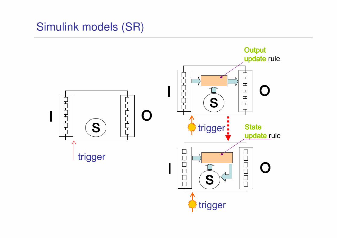
Simulink models (SR)
SSSSIIII OOOO
trigger
SSSSIIII OOOO
trigger
Output Output Output Output updateupdateupdateupdate rule
SSSSIIII OOOO
trigger
State State State State updateupdateupdateupdate rule

Simulink models (not feedthrough)
Integrator (output does not depend on input but only on state)
SSSSIIII OOOO
trigger
Output Output Output Output updateupdateupdateupdate rule
SSSSIIII OOOO
trigger
State State State State updateupdateupdateupdate rule

Example of generated code
SSSSIIII OOOO
trigger
Output Output Output Output updateupdateupdateupdate rule
SSSSIIII OOOO
trigger
State updateState updateState updateState updaterule

Simulink models (feedthrough)
Most blocks are of type feedthrough (output does depend on input)This implies a precedence constraint in the computation of the block output functions
Dependencies among outputs
Some blocks have no state

Simulation of models
• Simulation of Multirate models
– order all blocks based upon their topological dependencies
– The RTW tool (meant for a single processor implementation) generates a total order based on the partial order imposed by the feedthrough semantics
– In reality, there are many such total orders that satisfy the dependencies!
• Other choices are possible
• In multiprocessor implementations this can be leveraged to optimize the
implementation
– Then, for simulation, virtual time is initialized at zero
– The simulator scans the precedence list in order and execute allthe blocks for which the value of the virtual time is an integermultiple of the period of their inputs
– Simulated execution means computing the block output and then computing the new state

From Models to implementation
• Simulink case

Simulink models

Simulink models
The result is a network of functions (output/state update) with a set of partial orders
Each blockset is characterized by an execution rate

Simulation of mutirate models
• Simulation of multirate models: an example
– Simulation runs in virtual time. The virtual clock is updated ateach step

Motivation: Model-based devel. issues
• The implementation of a SR model should preserve its semantics so to retain the validation and verification results. The implementation can use
– Single task executing at the base rate of the system
– A set of concurrent tasks, with typically one task for each execution rate, and possibly more.
Simulation: logical execution and
communication time
A B
4
4 2 f(4,2)
D
tv=0 tv=1
C4 2
A B
3 1
tv=2
A B
2 0
D
T=1
T=1
T=2
T=4
B
A
C
D
3
12

From Models to implementation
• Simulink case (single task implementation)

From Models to implementation
• Simulink case (single task implementation)

Implementation of models
• Implementation runs in real-time (code implementing the blocks behavior has finite execution time)
• Generation of code: Singletask implementation

From Models to implementation
• Simulink case (single task implementation)
rt_OneStep()
{
Check for interrupt overflow or other error
Enable "rt_OneStep" (timer) interrupt
ModelStep-- Time step combines output,logging,update
}
Single-rate rt_OneStep is designed to execute model_step
within a single clock period. To enforce this timing
constraint, rt_OneStep maintains and checks a timer overrun flag.

Generation of code: multitask mode
• The RTW code generator assigns each block a task identifier (tid) based on its sample rate.
• The blocks with the fastest sample rates are executed by the task with the highest priority, the next slowest blocks are executed by a task with the next lower priority, and so on (Rate Monotonic)
1 1 12 4 4

Model implementation: single task
t=0 t=1 t=2 t=3 t=4
t=0 t=1 t=2 t=3 t=4
T=1
T=1
T=2
T=4
B
A 4
2
C
D
Easy but possibly inefficient
System base cycle = time to execute the longest system reaction

Model implementation: multi-task
Real-time execution: finite
execution time and
possible preemptionT=1
T=1T=2
T=4
B
A 4
2
C
D
A B
4 2
tr=1
A B
3 1
A B
2 0
D
C
f(4,1)?
tr=0
4 1
tv=2
C
Inconsistent data

Model implementation: multi-task
Real-time execution: lack
of time determinism
(because of preemption)T=1
T=1
T=2
T=4
B
A 4
2
C
D
A B
4 2
tr=1
A B
3 1
A B
2 0
D
f(3,1)
tr=0 31 tv=2
C
Behavior different from
simulation

From Models to implementation
• Multitask implementation
rt_OneStep()
{
Check for base-rate interrupt overflow
Enable "rt_OneStep" interrupt
Determine which rates need to run this time step
ModelStep(tid=0) --base-rate time step
For i=1:NumTasks -- iterate over sub-rate tasks
Check for sub-rate interrupt overflow
If (sub-rate task i is scheduled)
ModelStep(tid=i) --sub-rate time step
EndIf
EndFor
}

Nondeterminism in time and value
• However, this can lead to the violation of the zero-execution time semantics of the model (without delays) and even to inconsistentstate of the communication buffer in the case of – low rate (priority) blocks driving high rate (priority) blocks.
– high rate (priority) blocks driving low rate (priority) blocks.

Adding determinism: RT blocks
• Solution: Rate Transition blocks
– added buffer space and added latency/delay
– relax the scheduling problem by allowing to drop the feedthrough precedence constraint
• The mechanism can only be implemented if the rates of the blocks are harmonic (one multiple of the other)
– Otherwise, it is possible to make a transition to the gcdof the blocks’ periods, at the price of additional space and delay

RT blocks: High rate/priority to low rate/priority
High rate/
priority
Low rate/
priority
pri=1T=1
pri=1T=2
pri=2T=2
COSTspace: 1 additional set of variables for each linktime: overhead of RT implement.performance: none
COSTspace: 1 additional set of variables for each linktime: overhead of RT implement.performance: none
Output update only
Consistency here is guaranteed by proving there is no preemption

RT blocks: Low rate/priority to high rate/priority
Low rate/
priority
High rate/
priority
pri=2T=2
pri=2T=2
pri=1T=2
pri=1T=1
Output update
State update
Output update
RTRTRTRT----equivalentequivalentequivalentequivalent
COSTspace: 2 additional set of variables for each linktime: overhead of RT implement.performance: 1-unit delay (low rate period)
COSTspace: 2 additional set of variables for each linktime: overhead of RT implement.performance: 1-unit delay (low rate period) Consistency here is guaranteed
by proving there is no preemption

Limitations in the use of RT blocks (1)
Tradeoffs and design cycles
• RT blocks are not a functional entity– but an implementation device
• RT Blocks are only required – because of the selection of the RM scheduling policy
in slow to fast transitions
– because of the possibility of preemption
in both cases
• In both cases, time determinism (of communication) is obtained at the price of additional memory
• In the case of slow to fast transitions, the RT block also adds a delay equal to the period of the slowest block– This is only because of the Rate monotonic scheduling
– Added delays decrease the performance of controls

Consistency issues
• Consistency issues in the 1-1 communication between blockswith different rates may happen:
– When blocks are executed in concurrent tasks (activated at different
rates or by asynchronous events)
– When a reader may preempt a writer while updating the communication
variables (reader with higher priority than writer)
– When the writer can preempt the reader while it is reading the
communication variables (writer with higher priority).
– Necessary condition for data inconsistency is the possibility of
preemption reader→writer or writer→reader
• Also, we may want to enforce time determinism (flow preservation)

Consistency issues
• Also, a relaxed form of time determinism may be required
– Input coherency: when inputs are coming from multiple blocks, we want
to read inputs produced by instances activated by the same event
b1
b2
b3
T=2
T=1

Guaranteeing data consistency
• Demonstrate impossibility of preemption between readers and writers– Appropriate scheduling of blocks into tasks, priority assignment, activation
offsets and using worst-case response time analysis
• Avoid preemption between readers and writers– Disabling preemption among tasks (blocks) (RES_SCHEDULER in OSEK)
• Allow preemption and protect communication variables– Protect all the critical sections by
• Disabling interrupts
• Using (immediate) priority ceiling (semaphores/OSEK resources)
– Problem: need to protect each use of a communication variable. Advantage (does not require extra buffer memory, but only the additional memory of the protection mechanism)
– Lock-free/Wait-free communication: multiple buffers with protected copy instructions:
• Typically w. interrupt disabling or kernel-level code
- Problem: requires additional buffer memory (How much?). Advantage: it ispossible to cluster the write/read operations at the end/beginning of a task, with limited change to existing code.
- The best policy may be a mix of all the previous, depending on the timing contraints of the application and on the communication configuration.

Demonstrating impossibility of preemption
• Assign priorities and offsets and use timing analysis to guarantee absence of preemption
• Input data:– Mapping of functional blocks into tasks
– Order of functional blocks inside tasks
– Worst-case execution time of blocks (tasks)
– Priorities assigned to tasks
– Task periods
– (relative) Offset in the activation of periodic tasks (owr = minimum offset between writer and reader activations, Owr maximum offset between the activations)
• Computed data– Worst case response time of tasks/blocks (considering interferences and
preemptions) Rr for the writer Rw for the reader
• Two cases: – Priority writer > priority reader
– Priority reader > priority writer

Absence of preemption/High to low priority
• Condition for avoiding preemption writer→reader (no assumptionsabout relative rates of reader/writer)
High priority Low priority
OwrTw
Rr
Rr ≤ Tw - OwrRr ≤ Tw - Owr
w
r

Absence of preemption/Low to high priority
• Condition guaranteeing absence of preemption or reader to writer(reader→writer)
Low priority High priority
owr
Rw
owr ≥ Rwowr ≥ Rw
Both conditions are unlikely in practiceBoth conditions are unlikely in practice
Tr
Rw Owr=owr=0∧
Rw ≤ Tr
Owr=owr=0∧
Rw ≤ Tr
r
w
r
w

Absence of preemption/Low to high priority
• These conditions are ultimately used by the Rate Transition block mechanisms !!
Tr
Rw
Owr=owr=0∧
Rw ≤ Tr
Owr=owr=0∧
Rw ≤ Tr
r
w
Low
priority
High priority
pri=3T=2
pri=4T=2
pri=1T=2
pri=2T=1
Output update Output update

Avoiding preemption
• Disabling preemption
High priority Low priority
The response time of the high priority block/task is affected, need to check real-time properties
The response time of the high priority block/task is affected, need to check real-time properties
Low priority High priority

Design/Scheduling trade-offs
However ...
• if the communication is fast-to-slow and the slow block completes before the next instance of the fast writer, the RT block is not required
• if the communication is from slow to fast, it is possible to selectively preserve the precedence order (giving higher priority to the slow block) at the expense of schedulability
– Two tasks at the same rate, one high priority, the other low priority
T=4T=4T=4T=4 T=2T=2T=2T=2
T=4T=4T=4T=4 T=2T=2T=2T=2
T=1T=1T=1T=1 RTRTRTRTRTRTRTRTRTRTRTRT
No RT, no No RT, no No RT, no No RT, no delaydelaydelaydelay

An approach
Required steps• Definition of the network of functional blocks with
feedthrough dependencies
F1t1=1 F2
t2=1F3
t3=2 F5t5=1
F9t1=2 F10
t2=2
F12
t3=1
F11t11=1
F7
t7=2
F8t8=2
F4t4=1• Definition of the
synchronous sets
• Priority assignment and mapping into tasks
• Definition of the block order inside tasks
Type1 RTType2 RT

Preserving streams
• What buffering mechanisms are needed for the general
case ?
– Event-driven activation
– One-to-many communication
AB
C
D
A
B
C
D
0-delay behavior

Preserving streams
• What buffering mechanisms are needed for the general case ?
– Stream preservation (requirement)
– Event-driven activation
– One to many communication
AB
C
D
A
B
C
D
0-delay behavior
The value produced by this instance Is read by this
instance… and needs to be buffered in between

Preserving streams
AB
C
D
A
B
C
D
This block instance is assigned a buffer entry at the time of its activation
The entry is written at running time
This reader instance is assigned the buffer entry at the time of its activation
The entry is used by the reader at running time

Preserving streams
• The time the buffer index is assigned (activation of the block) may differ significantly from the time when the index is actually used (at running time) because of scheduling delays
– Support from the OS is needed for assigning indexes at block
activation times
A
B
C
D
This block instance is assigned a buffer entry at the time of its activation
The entry is written at running time
This reader instance is assigned the buffer entry at the time of its activation
The entry is used by the reader at running time

Preserving streams
• Many issues
– Defining efficient mechanisms for assigning indexes to the writers and the
readers (if they are executed at kernel level)
– Sizing the communication buffers (given the system characteristics, how
many buffers are needed?)
A
B
C
D
What buffer index is available at the time of the writer activation ?
This reader instance is assigned the buffer entry at the time of its activation
The entry is used by the reader at running time
It is not necessary to store all
these (6) values, there are at
most 3 readers at each time !

Model implementation: multi-task
• Efficient but issues with data integrity
and time determinism
bi bjoi(m) ij(k) oi(m+1)
oi(m)ij(k)
Defined at activation time
read at run time
oi(m+1)
Defined at activation time
written at run time
Q1:Q1:Q1:Q1: How many buffers you need? How many buffers you need? How many buffers you need? How many buffers you need? Q2: Q2: Q2: Q2: How do you define the index How do you define the index How do you define the index How do you define the index to be used (at activation time) and to be used (at activation time) and to be used (at activation time) and to be used (at activation time) and you pass to the runtime instance ?you pass to the runtime instance ?you pass to the runtime instance ?you pass to the runtime instance ?
Q1:Q1:Q1:Q1: How many buffers you need? How many buffers you need? How many buffers you need? How many buffers you need? Q2: Q2: Q2: Q2: How do you define the index How do you define the index How do you define the index How do you define the index to be used (at activation time) and to be used (at activation time) and to be used (at activation time) and to be used (at activation time) and you pass to the runtime instance ?you pass to the runtime instance ?you pass to the runtime instance ?you pass to the runtime instance ?
read here ? ik = oi(m)
or here ? ik = oi(m+1)

Buffer sizing methods
Two main methods
• preventing concurrent accesses by computing an upper bound for the maximum number of buffers that can be used at any given time by reader tasks. This number depends on the maximum number of reader instances that can be active at any time.
• Temporal concurrency control. The size of the buffer can be computed by upper bounding the number of times the writer can produce new values, while a given data item is considered valid by at least one reader.

Bounding the maximum number of reader instances
• the size is equal to the maximum number N of reader task instances that can be active at any time (the number of reader tasks if d≤T), plus two more buffers: one for the latest written data and one for use by the writer [Chen97] (no additional information is available, and no delays on the links).
Reader instance 1
Reader instance 3Reader instance 4
Reader instance N
Reader instance i
Reader instance 2
The writer must discover the available buffer index at runtime
A linked list implementation may trade space for time (O(1) access)

Temporal concurrency control
• Based on the concept of datum lifetime. The writer must not overwrite a buffer until the datum stored in it is still valid for some reader.
writer uses index i
reader gets item i
The writer simply writes at the next (modulo N) index
Owr
Tw
lifetime lwr = Owr+ max(Rri)
i i+1 i-1
Item I can be reused when no reader can access it
i
dri

Combination
• A combination of the temporal concurrency control and the bounded number of readers approaches can be used to obtain a tighter sizing of the buffer.
• Reader tasks are partitioned into two groups: fast and slow readers. The buffer bound for the fast readers leverages the lifetime-based bound of temporal concurrency control, and the size bound for the slow ones leverages information on the maximum number of reader instances that can be active at any time. Overall, the space requirements are reduced.

Combination
• Readers of τwi are sorted by increasing lifetime (li≤li+1). The bound
• Applies to readers with lifetime ≤ lj (fast readers).• Once j is chosen, the bound is
Buffer shared among fast readers based on the
number of reader instances inside the lifetime

Modeling Real-time systems
• What type of timing constraints are in a Simulink
diagram?

Modeling Distributed Real-time systems
• Where is the task model, the implementation relation and the deployment model?
Platform
instance
Application
instance
Platform API (OSEK/AUTOSAR)
Refinement into a set of concurrent tasks exchanging messages
Single-processor w. priority-based RTOSSingle-processor w. priority-based RTOS
SR modeling (Simulink)SR modeling (Simulink)
Dist. system w. asynchronous network (CAN)Dist. system w. asynchronous network (CAN) Dist. system w. time-triggered network (FlexRay)Dist. system w. time-triggered network (FlexRay)

Distributed implementation of models
Need to characterize
the scheduling delays
(how? cosimulation?) Remote blocks are
no more reacting at
the same time
TaskCPU
CPUTask
CAN
bus

Heterogeneous Network topology
BECs
IMU
SAS
EPS
BCM
IPC
ECC
Radio
On*
SDM
AOS
EPB
Immo
LI
N
HVSM
RFAVICM
SRC
PDIM
TID
PEPS
UPA
HSWM
Battery
EMB
Brake-
by-Wire
mtrmtr
FlexRay
LS GMLAN
P/T Exp Bus
Boost180V to 360V
DLC1
DLC2
Chas Exp Bus
mtrmtr
TPIM
PIM
HCP
MCPB
ATPC
PIMPIM
mtr
120 kW
pump
HS GMLAN
360
VAC
MCPA
8 kW
HeaterPIM
2 kW
ARP
PIM 1 kW
Ht Pump
PIM
11 kW/ 25 kW
Air Comp
78 kW
@180V
Fuel Cell
ControllerFCS
SIB
CVM
Fuel Cell Sys
ControllerFCPS
H2 Sensors
Refuel Data Int
X31F
CAN
FlexRay
Architectures are heterogeneous systems
FlexRay (time-
triggered)
subsystem
CAN (event-
based)
subsystem

Delays from network
A very simple model with oversampling ….
Imagine the data streams between source blocks and the
multiplier/comparator are exchanged over a network.
These are the results seen by the control engineer at design
time

Delays from network
An example of the trade-offs between additional
functional delays and scheduling feasibility
Block Aperiod = 4
Block Bperiod = 4
Block Cperiod = 4
A B C C C C A B C

Delays from network
Designers may be tempted to ease the scheduling
problem by choosing the instance of the receiving task/block

Delays from network
Unfortunately, by doing so, the behavior is different from the one simulated with 0-delay
Are the designers/developers fully aware of these issues ?How can we help them ?
(Task and message design and scheduling are in the background)

Delays from network
Unfortunately, solutions like this are possible
(not to mention issues with low-level communication levels /drivers and custom code)

Architecture optimization vs features- Active and Passive Safety
by Leen and Effernan – IEEE Computer

Active and Passive Safety
by Leen and Effernan – IEEE Computer

ACC (from Continental web site)
• Adaptive Cruise Control (ACC) – Chassis ElectronicsCombined with Safety Aspects
As with conventional cruise control, the driver
specifies the desired velocity - ACC
consistently maintains this desired speed.
In addition, the driver can enter the desired
distance to a vehicle driving in front.
If the vehicle now approaches a car travelling
more slowly in the same lane, ACC will
recognize the diminishing distance and
reduce the speed through intervention in the
motor management and by braking with a
maximum of 0.2 to 0.3 g until the preselected
distance is reached. If the lane is clear again,
ACC will accelerate to the previously selected
desired tempo.

Evolution of Integrated Functions
Speed-dependant volume
Onstar emergency notification
Bo
dy
HV
AC
ACCPre-2004
Stabilitrak 2
function6
function5
to 2010/12
to 2012/14
Post-2014 function17
Tele
matic
s
Tra
nsm
iss.
En
gin
e
Occu
pan
t In
form
atio
n
Exte
rior
ligh
ting
Occ.
pro
tectio
n
Info
tain
m.
En
viro
nm
. sen
sin
g
Ob
ject
dete
ctio
n
Su
sp
en
sio
n
Ste
erin
g
Bra
ke
Su
bs
yste
m
function7
function8
function9
function10
function11
function12
function13
function14
function15
function16

Automotive architecture trends
• An increasing number of functions will be distributed on a
decreasing number of ECUs and enabled through an increasing number of smart sensors and actuators
• today: > 5 buses and > 30 ECUs
• 90% of innovation in cars for the foreseeable future will be
enabled through the Electronic Vehicle Architecture
• Transition from single-ECU Black-box based development
processes to a system-level engineering process• System-level methodologies for quantitative exploration and selection,
• From Hardware Emulation to Model Based Verification of the System
• Architectures need to be defined years ahead of production
time, with incomplete information about (future) features
• Multiple non-functional requirements can be defined

f1 f2 f3 f4
f5 f6
s4
s5
s2
s3
s1
Functional
model
deadline
Jitter constraint
functionperiodactivation mode
signalperiod
is_triggerprecedence
Input interface
Output
interface
Functional model

f1 f2 f3 f4
f5 f6
s4
s5
s2
s3
s1
ECU2ECU1 ECU3
OSEK1CAN1
Functional
model
Execution
architect.
model
ECUclk speed (Mhz)
register width
busspeed (b/s)
Architecture model

f1 f2 f3 f4
f5 f6
s4
s5
s2
s3
s1
ECU2ECU1 ECU3
OSEK1CAN1
task1 task2task3 task4
Functional
model
System
platform model
Execution
architect.
model
SR1 msg1
msg2taskperiodpriorityWCETactiv.mode
messageCANIdperiodlengthtransm. modeis_trigger
resourceWCBT
Deployment model

Deployment: An example
EPS
EHPS
.
ITBC
MSB 1
MSB 2AFL
PALC
-
3
1
2
4
End-to-end
latencies
ECU and bus
utilizations
F A
M
QA

Back to architecture synthesis
Periods
Activation modesSystem
Functionality
Flow To Implementation
SystemArchitecture
Mapping
Performance
Analysis
Refinement
Task and
message
priorities
Function to ECU
allocation
Number and type of
ECUs and buses
System topology
Function to task
mapping
DATE 07 (MILP)
RTAS 07 (B&B)
DAC 07 (GP)
RTSS 07 (MILP)
Simul. annealing
Extensibility RTAS 08 (MILP+search)

Approach: Mathematical Programming
• Why Mathematical Programming?
• (compared with search, genetic programming or SA …)– Simplicity
• Problem represented with: – Set of decision variables
– Constraints
– Objective function
• “automatically” handles cross dependency among selection choices
– Easier coding of multi-objective optimization
– Standardized approach• Well established technique
• Sound theory, methods
• Availability of commercial solvers (in essence, search engines)
– How good is your solution?• Provides safe estimate of optimal solution
• Provides intermediate solutions of increasing quality
• Challenge:– Capture the problem and obtain efficient runtimes
85

(Example) Problem Formulation
Minimization of (average case) end-to-end latenciesMinimization of (average case) end-to-end latencies
• Placement of tasks onto the CPUs
• Packing of signals to messages
• Assignment of priorities to tasks and messages
• Definition of activation modes/synchronization model
• Period optimization
• Placement of tasks onto the CPUs
• Packing of signals to messages
• Assignment of priorities to tasks and messages
• Definition of activation modes/synchronization model
• Period optimization
• Constraints on end-to-end latencies• Constraints on messages size
• Constraints on utilization
• Constraints on message and task deadlines• Semantics preservation constraints
• Constraints on end-to-end latencies• Constraints on messages size
• Constraints on utilization
• Constraints on message and task deadlines• Semantics preservation constraints
Objective
Subject to
Design objectives
(optimization variables)

Periodic Activation Model
End-to-endlatencyanalysis
Periodicasynchronous
activation modelHigh latency, but allows decoupling the scheduling
problem
ECU1 CAN
ECU2
ττττ1ev0
ev0
m2 ττττ3
where (approx.)
ECU3
m4 ττττ5
ττττ1
rT1 T1
T2
ττττ1
m2
ττττ3
m2rT2

88
Worst Case Response Times
Tasks:
Messages:
• Resource utilization
– Fraction of time the resource (ECU or bus)
spends processing its objects (tasks or messages)
• Utilization bounds less than 100%
– To allow for future extensibility
R∈∀≤
∑
→
jj
Roi i
i Rut
c
ji:

Event-based Activation Model
End-to-endlatencyanalysis
Data-driven precedenceconstrained activation
modelLower latency for high priority paths, jitter increases along the
path
Lower latency for high priority paths, jitter increases along the
path
ECU1 CAN
ECU2
ττττ1ev0
m2 ττττ3
ECU3
m4 ττττ5
where (approx.)
J3
T1 ττττ1
m2
ττττ3
ττττ1
w
m2w

Design Process and Requirements
• Design optimization
x2
x1
X space of design optimization
variables, such as computation
times, periods, placement,
priorities …
Schedulability of task i
Schedulability of task j

Design Process and Requirements
• Design optimization
x2
x1
Schedulability(feasibility) region
Communication constraints
X space of design optimization
variables, such as computation
times, periods, placement,
priorities …

Design Process and Requirements
• Design optimization
x2
x1
Constraints
Schedulability
Communication…
Semantics preservation
X space of design optimization
variables, such as computation
times, periods, placement,
priorities …

Design Process and Requirements
• Design optimization
x2
x1
Constraints
Schedulability
CommunicationModel Semantics preservation…
Sensitivity (extensibility)
X space of design optimization
variables, such as computation
times, periods, placement,
priorities …

Design Process and Requirements
• Design optimization
x2
x1
X (discrete) space of design
optimization variables, such as
computation times, placement,
priorities, periods …
Constraints
Schedulability
CommunicationModel Semantics preservationExtensibility

Design Process and Requirements
• Design optimization
x2
x1
X (discrete) space of design
optimization variables, such as
computation times, periods …
Constraints
Schedulability
CommunicationModel Semantics preservationExtensibility
Metrics
Control related
Optimal design

(Example) Problem Formulation
Minimization of (average case) end-to-end latenciesMinimization of (average case) end-to-end latencies
• Placement of tasks onto the CPUs
• Packing of signals to messages
• Assignment of priorities to tasks and messages
• Definition of activation modes/synchronization model
• Period optimization
• Placement of tasks onto the CPUs
• Packing of signals to messages
• Assignment of priorities to tasks and messages
• Definition of activation modes/synchronization model
• Period optimization
• Constraints on end-to-end latencies
• Constraints on messages size
• Constraints on utilization
• Constraints on message and task deadlines
• Semantics preservation constraints
• Constraints on end-to-end latencies
• Constraints on messages size
• Constraints on utilization
• Constraints on message and task deadlines
• Semantics preservation constraints
Objective
Subject to
Design objectives
(optimization variables)

Stochastic analysis
62 msg set (subset of chassis bus). Low priority msg – Distributions of latencies

Statistical analysis of CAN msgs
• Collected distributions of CAN message latencies by simulation
on automotive buses (5 “realistic msgs configurations” and 20+
more obtained by derivation with changes in the load)
Typical shape of
cdf

Statistical analysis of CAN msgs
• Can we fit the latency cdf with a “well-known” statistical distribution?
• What would be the accuracy?
Fitting with a gamma
distribution
An exponential fitting
also returns good
results!

Statistical analysis of CAN msgs
• Finally, can we estimate the offsets and the parameters of the
Gamma distribution (a, b) or (µ,b) for each message by regression from parameters of the message set like Ui
r, Uihr,Qi, Qi
hr ?
Using regression
formulas as predictors
for Xoff, Yoff, µ and b
Example:
formula for µ
Example: medimum
priority msg

101
Conclusions
• Schedulability theory and worst-case timing analysis …
– From the run-time domain to the design domain (already happening)
– From the analysis domain to the optimization (synthesis)
domain
– Complemented by sensitivity analysis and uncertainty
evaluation
• However …
– Typical deadline analysis is not enough!
– Tasks and messages are not the starting point (semantics preservation issues from functional models to tasking models)
– Worst case analysis needs to be complemented
– Mixed domains (time-triggered / event-triggered)

Q&A
Thank you!