CPLpublications.lib.chalmers.se/records/fulltext/local...For modeling of interfaces with complex...
13
_____________________________________________ CPL Chalmers Publication Library Institutional Repository of Chalmers University of Technology http://publications.lib.chalmers.se ____________________________________________ Copyright notice (post print) Taylor & Francis This is an electronic version of an article published in Philosophical Magazine Letters, 90 (8) p.599-609 http://dx.doi.org/10.1080/09500831003800863
Transcript of CPLpublications.lib.chalmers.se/records/fulltext/local...For modeling of interfaces with complex...

_____________________________________________
CPL Chalmers Publication Library
Institutional Repository of
Chalmers University of Technology
http://publications.lib.chalmers.se
____________________________________________
Copyright notice (post print) Taylor & Francis
This is an electronic version of an article published in Philosophical Magazine Letters, 90 (8) p.599-609
http://dx.doi.org/10.1080/09500831003800863

This is an electronic version of an article published inPhilosophical Magazine Letters Vol. 90, No. 8, August 2010, 599–609.DOI: 10.1080/09500831003800863
RESEARCH ARTICLE
Theory of ultrathin films at metal-ceramic interfaces
Sven A. E. Johansson∗ and Goran Wahnstrom
Department of Applied Physics, Chalmers University of Technology, SE-412 96 Goteborg,
Sweden
(February 21, 2012)
A theoretical model for understanding the formation of interfacial thin films is presented,which combines density functional theory calculations for interface energies with thermody-namic modeling techniques for multicomponent bulk systems. The theory is applied to thinfilm formation in VC-doped WC-Co cemented carbides. It is predicted that ultrathin VC filmsmay exist in WC/Co interfaces at the high temperature sintering conditions where most ofthe WC grain growth occurs, which provides an explanation of the grain growth inhibitingeffect of VC additions in the WC-Co system.
Keywords: interface energy; interface structure; first-principles calculations; cementedcarbides; grain growth inhibitors
1. Introduction
Ultrathin films are essential for many applications in nanoscale science and technol-ogy. Considerable scientific interest is devoted to thin oxide films at metal surfaces[1–3], for which applications are found in catalysis, semiconductor devices as well asmechanical wear and corrosion protection. Correctly assessing the thermodynamicstability of such films is an important issue [4]. New thin film surface alloys havebeen discovered and the stability of nano-sized patterns in the ultrathin films in-vestigated with respect to strain and chemical effects [5, 6]. Formation of ultrathinfilms is also observed in metal-ceramic materials after sintering of nanoparticlesinto a bulk nanocrystalline material [7].
In this Letter, we consider an interface between two dissimilar materials, a metal-ceramic interface, and the propensity to form, at the interface, an ultrathin filmof a secondary phase, whose corresponding bulk phase is thermodynamically un-stable. We develop a model for the thin film formation and stability as function oftemperature and show that it can be stabilized by interfacial effects.
For modeling of interfaces with complex bonding such as metal-ceramic inter-faces, first-principles calculations in the framework of density functional theory(DFT) has proved to be a very useful tool [8–10]. However, phase stabilities athigh temperatures are cumbersome to predict with sufficient accuracy using DFT[11] and therefore we combine DFT calculations with driving forces of nucleationfrom well-developed thermodynamic modeling techniques [12]. These modelingtechniques describe bulk phases but lack information on interfacial effects.
∗Corresponding author. Email: [email protected]

2 Sven A. E. Johansson and Goran Wahnstrom
We apply the developed methodology to WC-Co cemented carbides. These ma-terials are produced by means of powder metallurgy, where powders of carbidesand metal Co are sintered together into a hard and dense material with excellentmechanical properties. The materials are used in cutting and wear resistant toolsand are of considerable industrial importance. Much effort has been invested in de-veloping nanostructured cemented carbides by reducing the mean WC grain size inthe finished product, because a fine and homogeneous microstructure has superiormechanical properties [13]. To control the microstructure and retain a fine grainsize throughout the sintering, dopants in the form of VC, Cr3C2, TiC, TaC or NbCpowders are added, of which VC has proved to be the most effective inhibitor inultrafine alloys [14]. The grain growth inhibiting effect of the dopants is well estab-lished, whereas the inhibiting mechanism on the atomic scale is not understood.Experimental high-resolution electron microscopy (HREM) studies [15–19] haveshown the existence of V- and Cr-rich films of cubic carbide structure at WC/Cointerfaces in VC- and Cr3C2-doped materials, respectively, at low temperatures,after liquid phase sintering and cooling. In order to predict the possible growthinhibiting effect of such films, it is decisive to determine whether these can exist athigh temperature liquid phase sintering conditions, where most of the grain growthoccurs and where HREM cannot be applied.
2. Model
2.1. General description
The interface energy γ can be expressed as the excess Gibbs energy per unit inter-face area due to the presence of an interface [20],
γ =1
A
(G−
∑i
niµi
). (1)
G is the Gibbs energy for the entire considered system, which contains an inter-face of area A. ni is the number of atoms in the system of component i with acorresponding chemical potential µi determined by the reservoirs with which thesystem is in equilibrium. In the present case, the reservoirs are stoichiometric WCand a binder phase. The latter consists of mainly Co (and will be denoted “Co”)but also of dissolved W, C, and M atoms, where M = V, Cr, Ti, etc. depending onthe doping.
We consider the propensity to form a thin film consisting of N layers of carbidephase, here denoted MC, at the interface between WC and the binder phase. Forsufficiently thick films, the interface can be regarded as split into a WC/MC in-terface and a MC/Co interface separated by a slab of MC. The energy for such afilm-covered interface can then be decomposed as
γfilm = γWC/MC + γMC/Co +N (∆gMC + eMC) , (2)
where γWC/MC (γMC/Co) is the interface energy between WC and MC (MC andCo). The last term of Eq. (2) represents the energetic cost per layer of building theMC phase and, thus, increases linearly with the number of layers N of the film. Forthe corresponding energy per formula unit we use the notation ∆gMC = S∆gMC,where S is the interface area of one formula unit. The energy ∆gMC is the negative

3
N ���
∆g ��� + e ���
������ ��
N � � ��� ���� ������ ��
∆γ
��
γ � � �
Figure 1. A schematic illustration of γfilm as function of film thickness N . The circles denote the energyin an atomistic treatment and the solid line follows the decomposition in Eq. (2).
driving force of nucleation. Assuming a stoichiometric carbide phase, it equals
∆gMC = gMC − µM − µC, (3)
where gMC is the Gibbs energy per formula unit of MC and µM (µC) is the chemicalpotential of M (C). A positive value of ∆gMC thus implies that the MC phase isunstable. We consider coherently strained thin films and the last quantity of Eq. (2),eMC, is the strain energy per layer needed to bring the film into epitaxy with theunderlying WC.
The energy γfilm should be compared with the energy γWC/Co of a WC/Co inter-face not covered by any MC film. The film is stable if γfilm < γWC/Co and, hence,a positive value of
∆γMC = γWC/Co −(γWC/MC + γMC/Co
)(4)
indicates that film formation is possible. An upper limit of the film thickness Nlimit
is found where the energy of the film-covered interface matches the energy of theuncovered interface, γfilm = γWC/Co, which yields
Nlimit =∆γMC
∆gMC + eMC. (5)
If Nlimit is larger than a few atomic layers, the interface may contain a thin film.The decomposition of γfilm in Eq. (2) is valid only if the film is sufficiently thick,
so that the interior of the film is bulk-like and the interface energies are well-defined.For thin films, γfilm will deviate from the linear dependence on N , which impliesthat γfilm can have a minimum as function of N for a finite film thickness. In equi-librium, this optimal film thickness Neq will be attained. A schematic illustrationof γfilm is given in Figure 1.
2.2. Specific model and method
In the present paper we concentrate on VC-doped WC-Co. Results for other MCdopants will be presented elsewhere [21]. WC has a simple hexagonal lattice struc-ture. After liquid-phase sintering in Co, the WC grains are predominantly delimitedby their basal (0001) and prismatic (1010) surfaces [22]. Here, we focus on the basalsurface, which can be either W- or C-terminated. We choose the WC surface andthe cubic VC phase to be oriented according to
(0001)WC ‖ (111)VC , [1210]WC ‖ [110]VC . (6)
4 Sven A. E. Johansson and Goran Wahnstrom
This orientation relationship between WC and MC has been experimentally estab-lished for both V- and Cr-doped WC-Co [18, 23].
Interface calculations are performed using DFT and the current computationalmethodology has been developed in a series of papers [24–26]. Computational re-sults have been compared with experimental data [24, 25] and the use of the gen-eralized gradient approximation (GGA) for the exchange-correlation effects withinDFT in interface calculations has been motivated [26]. Further computational de-tails can be found in [27].
To model the interfaces, we use standard supercell slab geometries, where theinterfaces are made coherent by straining the VC and Co phases to match theWC basal surface. The associated strain energies are minimized by relaxing theinterplanar distances to account for the Poisson effect. In the calculation of interfaceenergies, the strain energies are canceled, so that γWC/VC, γVC/Co, and γWC/Co
represent the chemical contribution to the interface energy and do not depend onsystem size.
To define an absolute value of the interface energy, a definite value of the carbonchemical potential µC is required. Within the two-phase region (WC+Co) of theW-C-Co system, µC can be varied in a small interval limited by the formation ofeither graphite or a metal-carbide phase (W,Co)6C [28]. We assume carbon to bein equilibrium with graphite and use the corresponding computed value for µC [10].
3. Results and discussion
3.1. Interface energies
In the 〈0001〉WC and 〈111〉VC directions, the WC and VC phases consist of al-ternating layers of metal and carbon atoms. Assigning the positions A to (0, 0),B to (1
3 ,23) and C to (2
3 ,13) with respect to hexagonal lattice vectors in the
(0001)WC plane, the stacking sequence for WC is . . .WACBWACB . . . and for VC. . .VACCVBCAVCCB . . . along [0001]WC and [111]VC, respectively. We have calcu-lated interface energies for all possible stacking sequences involving the A, B and Cpositions and varying atomic terminations of the phases. Only stoichiometric VCcompounds are considered. To assign a value of γWC/VC, we pick the lowest energyamong the different stackings and terminations. The resulting interface energy isfound to be slightly negative, γWC/VC = −0.03 J/m2 [27].
The predicted WC/VC interface structure can be compared with experimen-tal findings. By comparing experimental and simulated HREM images of aWC(0001)/VC(111) interface in a VC-doped WC-Co, a particular interfacial stack-ing has been suggested [29]. We find that the lowest energy is obtained for. . .CBWACBVACCVBCA . . . [27] which is in complete agreement with the stackingsuggested in Ref. [29].
The WC/Co and VC/Co interfaces need to be treated with more concern, sinceat relevant sintering temperatures, the Co binder is in its liquid phase. A solid-liquid interface energy is usually considered as stemming from two separate parts(see, e.g. [30]): a chemical contribution due to differing atomic bonding at theinterface, and a structural contribution due to disturbance of the liquid’s structurecaused by the interface. One should notice, that only the difference between thetwo interface energies γWC/Co and γVC/Co enters into the expression (4) for the keyquantity ∆γVC. Therefore, the geometrical similarity of the WC(0001) and VC(111)surfaces implies that structural contributions to ∆γVC will to large extent cancel.
We choose to model the WC/Co and VC/Co interfaces in the same geom-etry as the WC/VC interface, which means that we are effectively modeling
5
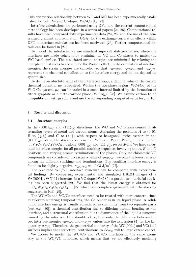
Figure 2. The optimal atomic structure of a WC/VC/Co interface containing two layers ofstoichiometric VC. Top: Atomic positions projected onto a plane with normal [1210]WC. Bottom: Thepositions of the V, C and Co atoms closest to the interface projected onto the interface plane. The sixdepicted atomic configurations of Co are used to calculate a mean value of the carbide/Co interfaceenergy for the thin film configuration. The same set of relative translations and rotations of Co with
respect to the topmost carbide layer is also used in calculating WC/Co and VC/Co interface energies.
WC(0001)/Co(111) and VC(111)/Co(111) interfaces with different Co stackings.Following the preceding argument, we do not expect the particular choice of Coorientation to influence ∆γVC in any decisive way, although existing experimentalobservations of this orientation between WC and solid Co [31, 32] do motivateits use as model geometry. At high temperatures, the motion of liquid Co atomswill constantly change the atomic structure at the interface. Therefore, we use amean value of energies for different stackings of Co in the interface to approximateγWC/Co and γVC/Co, respectively. In Figure 2 we depict the six different atomic ar-rangements of Co used in calculating the mean energy of the carbide/Co interface.The resulting value for the interface energy can be regarded as a good approxi-mation for an incoherent interface [33]. The termination of the WC or VC slabs(metallic or C) is consistently chosen to yield the lowest mean interface energy.
We find that for WC/Co, the interface is C-terminated with an energy γWC/Co =
1.01 J/m2 [27]. For VC/Co, the interface is V-terminated with γVC/Co = 0.00 J/m2
[27]. The resulting difference in interface energy is ∆γVC = 1.03 J/m2, which wehenceforth will assume to be temperature independent.
The final result of ∆γVC does not strongly depend on the choice of averagingof the various Co stackings in the interfaces. For instance, by following the aboveprocedure but disregarding the two most high-energetic configurations in each in-terface, ∆γVC increases by 0.14 J/m2. The impact on ∆γVC due to ordering ofthe liquid Co atoms in the vicinity of the WC or VC interfaces is therefore ex-pected to be maximally of this size. Temperature-dependent deviations from ourestimation of ∆γVC may arise from differences in the vibrational spectrum of V,W, and C atoms at the interface as compared with their respective reference states.Following the procedure of Reuter and Scheffler [34], we estimate this effect to bemaximally ±0.3 J/m2. Considering both these effects, we expect ∆γVC to be deter-mined within an accuracy of ±0.35 J/m2. By accounting for a mixed carbide layerinstead of the stoichiometric VC compounds considered so far, further entropic

6 Sven A. E. Johansson and Goran Wahnstrom
1300 1400 1500 1600 17000
0.02
0.04
0.06
0.08
0.1
T (K)
∆g (e
V p
er fo
rmul
a un
it )
y1y2
y4
y3
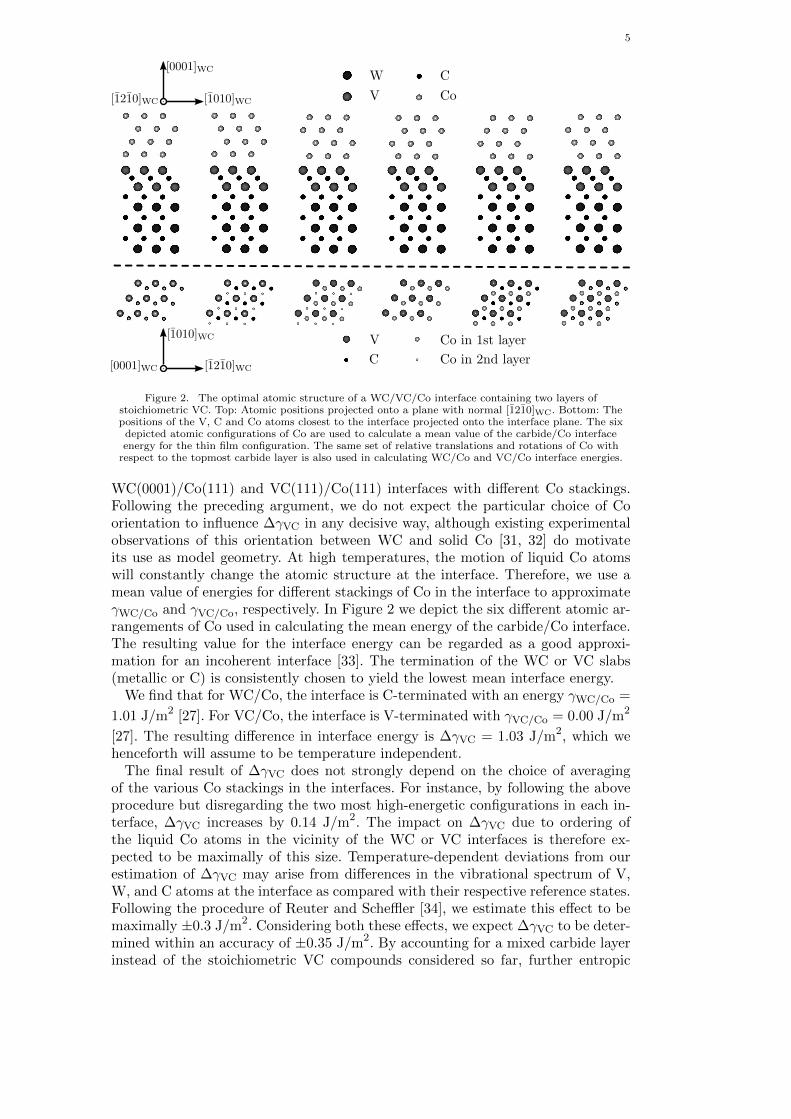
Figure 3. ∆g(V,W,Co)Cxas function of temperature T in a W-C-Co-V system in equilibrium with WC
and graphite. yi denotes the V/Co atomic ratio and y1 = 6.4 · 10−3, y2 = 2.6 · 10−2, y3 = 5.1 · 10−2 andy4 = 7.7 · 10−2.
effects are introduced (see below).
3.2. Thin film energy and composition
In addition to ∆γVC, the energetic costs, ∆gVC and eVC, to build the VC thin filmsare needed to predict stability. To compress VC from its calculated equilibriumlattice parameter in the interface, aVC/
√2 = 2.944 A, to the calculated WC lattice
parameter, aWC = 2.919 A, an energy of only eVC = 0.011 J/m2 (0.005 eV per VCformula unit) is required.
The driving force of nucleation, −∆gVC, depends sensitively on the temperatureand composition of the system. The most stable cubic carbide is not stoichiometricVC, but a mixed (V,W,Co)Cx phase. In its at 1593 K experimentally measuredcomposition, V constitute 75% and W 23% of the metallic atoms and the C vacancyconcentration is 11% [28]. To determine the driving force of nucleation we have usedthe Thermocalc software [12] with a database for Cr and V additions in the W-C-Co system [28]. The database has been assessed from experimental observationsusing the Calphad method and models temperature dependent Gibbs energies ofthe phases occurring in the W-C-Co system.
In Figure 3, the negative driving force of nucleation ∆g(V,W,Co)Cx
for a(V,W,Co)Cx phase of optimal composition with respect to Gibbs energy in a W-C-Co-V system in equilibrium with WC and graphite is given as a function of tem-perature for varying V/Co atomic ratio yi. For low temperatures, ∆g(V,W,Co)C
x= 0
for all considered doping levels, meaning that stable (V,W,Co)Cx precipitates existat these chemical conditions. The sharp increase of ∆g(V,W,Co)C
xat temperatures
around 1550 K is due to the melting of the binder phase, which significantly in-creases its solubility of V. At the doping levels y2 and y3 of Figure 3, the thermody-namic calculation (which lacks any model for interface stabilization) predicts thatall (V,W,Co)Cx phase would dissolve as the binder melts. A discontinuous changein the slope of ∆g(V,W,Co)C
xis also found near 1300 K for y1. This change is as-
sociated with the transition of the solid Co binder from its ferro- to paramagneticphase. We conclude that for relevant doping concentrations, ∆g(V,W,Co)C
xvaries
between 0 and 0.1 eV (corresponding to 0 and 0.22 J/m2 per layer of (V,W,Co)Cx).We can now summarize our results for the propensity of thin film formation.
In Figure 5, the solid line corresponds to the result from Eq. (2) for VC. Here,we set ∆gVC = 0.06 eV, which is a reasonable choice based on the results fromour thermodynamic modeling at relevant sintering temperatures. With this valueof ∆gVC, Eq. (5) suggests that stable films of thickness less than Nlimit = 7 may

7
exist.In the interface calculations, we have approximated the film carbide phase with
a stoichiometric VC phase. The real film may well have a composition similar tothe bulk (V,W,Co)Cx phase, though finding the optimal composition would requirenumerous large interface calculations. To assess the effect of composition, we haveperformed a calculation for a mixed (V0.75,W0.25)C phase, whose composition isclose to the experimentally measured one of bulk (V,W,Co)Cx [28]. We obtain
γ(V0.75,W0.25)C/Co = −0.15 J/m2 < γVC/Co [27] and, therefore, we expect that forthe true composition, the interfacial effect will further stabilize the thin film.
3.3. Explicit atomistic layer-by-layer treatment
The expression for γfilm in Eq. (2) is only valid if the film is sufficiently thick. Forthinner films, the details of the atomic layer-by-layer structure has to be taken intoaccount. We have therefore explicitly modeled the atomic layer-by-layer structureof thin films of cubic VC at the WC/Co interface. The number of possible stackingsequences of VC in the WC/VC/Co interface is large, but can be decreased byomitting obviously high-energetic configurations. In total, we have considered 76different VC stacking sequences with six corresponding Co stackings for each ofthese [27].
In Figure 4, the energy of a WC/Co interface containing a VC film is given asa function of the number of metallic V layers in the film for different VC stackingsequences. The results for the stackings corresponding to the minimal energy inthe WC/VC interface described earlier are circled. In the plot, we show the resultwithout adding any contribution from the energetic cost per layer to build thethin film (∆gVC + eVC = 0). The result should then converge to γWC/VC + γVC/Co
for sufficiently thick films. We find that the result is close to the asymptotic valuealready for two V layers, while the result for one V layer deviates both energeticallyand structurally with . . .CBWACBVCCo . . . being the optimal stacking in this case.The optimal structure in the case of two V layers is depicted in Figure 2.
Our final results are presented as circles in Figure 5, where we again set∆gVC = 0.06 eV. To calculate γfilm(N), we take for each number of V layersN the minimum energy among the stackings and terminations presented in Fig-ure 4 and add N (∆gVC + eVC). The fast convergence of the interface energiestoward the asymptotic value of Eq. (2) implies that a thin film with two V lay-ers will be the most stable configuration for a rather wide interval of ∆gVC,0.01 eV . ∆gVC . 0.2 eV. For no value of ∆gVC will one V layer be the moststable configuration. With the values used in Figure 5, we find that the interfacewith a VC film is favored by 0.68 J/m2 compared to the interface without segre-gated VC. This value lies well outside our estimated error bound of ±0.35 J/m2
indicating that in equilibrium, the WC(0001) surface is indeed covered by VC.Our prediction of a few stable V layers agrees very well with HREM imaging
[7, 18, 19, 29], where thin films on WC(0001) in VC-doped material are seen to havea thickness of two and sometimes a few additional metallic layers. An interpretationof the additional layers is that they precipitate as ∆gVC → 0 during cooling. TheVC-covered surface is also a likely nucleation site for further growth of the VCphase, which sometimes builds up as a precipitate on WC(0001) during cooling[18, 29].

8 Sven A. E. Johansson and Goran Wahnstrom
0 1 2 3 4 5
0.0
0.5
1.0
1.5
2.0
2.5
3.0
3.5
N
γ film
(J/m
2 )
γWC/CoγWC/VC + γVC/Co
Figure 4. Interface energy γfilm as a function of the number of V layers N in a cubic VC film in theWC/Co interface for different stackings of VC. + (x) denotes a C-terminated (metal-terminated)
carbide/Co interface. The stacking sequence that corresponds to the minimal WC/VC interface energy iscircled. No energetic cost per layer to build the thin film is added (∆gVC + eVC = 0).
0 1 2 3 4 5
0
0.2
0.4
0.6
0.8
1
N
γ film
(J/m
2 )
γWC/Co
Eq. (2)Atomistic
Figure 5. Interface energy γfilm as a function of the number of V layers N in a cubic VC film in theWC/Co interface. ∆gVC is set to 0.06 eV per formula unit, which is an appropriate value for relevant
doping conditions and sintering temperatures. A thin film of two V layers will be the most stableconfiguration for a rather wide interval of ∆gVC, 0.01 eV . ∆gVC . 0.2 eV.
3.4. Grain growth inhibiting effect
It is generally believed that the rate limiting step of grain growth in WC-Co systemsis the dissolution and/or reprecipitation reactions occuring at WC/Co interfaces.Several authors have therefore attributed the growth inhibiting effect of V to aproposed interference with these reactions either through blocking active growth
REFERENCES 9
centers at the WC surface [35, 36] or through the presence of segregated V atthe WC surface [15, 19], which would hinder W diffusion into or out of the WCgrain. Our prediction that ultrathin VC films may be present and stable also atliquid-phase sintering temperatures is supportive of the latter explanation.
4. Conclusions
We have developed an atomistic model for understanding thin film formation atinterfaces in bulk composite materials. We combine extensive density functionaltheory (DFT) calculations for interfaces and thin films with thermodynamic mod-eling techniques for multicomponent systems. The latter technique is used to obtainrelevant chemical potentials for the various components as function of temperatureand doping conditions.
The theory is applied to thin film formation in VC-doped WC-Co cementedcarbides. It is predicted that under realistic doping conditions, ultrathin films mayexist at high temperature liquid phase sintering conditions where most of the graingrowth occurs.
By explicit DFT modeling of the thin films as function of the number of atomiclayers, we find that the most stable configuration consists of only two V layers overa large temperature range and we show how the atomistic picture approaches thethick film limit with increasing number of layers.
The films, whose corresponding bulk phase is thermodynamically unstable, arestabilized by interfacial effects. Compared with the original interface in the absenceof a thin film, there is an energy gain associated with the creation of the two sub-interfaces involved in the thin film formation, which more than compensates forthe energetic cost of the thin film itself.
In conclusion, our results explain the formation of VC films in WC/Co interfaces.The presented method can be applied to theoretically assess the stability of othercarbide films in WC/Co interfaces.
Acknowledgments
Financial support from the Swedish Research Council, Sandvik and Seco Tools isgratefully acknowledged. Computations have been performed on SNIC resources.We thank Susanne Norgren, Sandvik Tooling, for providing thermodynamic calcu-lations.
References
[1] G. Kresse et al., Science 308 (2005), p. 1440.[2] J. Rogal, K. Reuter, and M. Scheffler, Phys. Rev. Lett. 98 (2007), p. 046101.[3] C. Freysoldt, P. Rinke, and M. Scheffler, Phys. Rev. Lett. 99 (2007), p. 086101.[4] C.T. Campbell, Phys. Rev. Lett. 96 (2006), p. 066106.[5] G.E. Thayer et al., Phys. Rev. Lett. 86 (2001), p. 660.[6] V. Ozolins, M. Asta, and J.J. Hoyt, Phys. Rev. Lett. 88 (2002), p. 096101.[7] S. Lay, M. Loubradou, and P. Donnadieu, Adv. Eng. Mater. 6(10) (2004), p. 811.[8] M.W. Finnis, J. Phys.: Condens. Matter 8 (1996), p. 5811.[9] S.V. Dudiy, J. Hartford, and B.I. Lundqvist, Phys. Rev. Lett. 85 (2000), p. 1898.
[10] M. Christensen et al., Phys. Rev. Lett. 94 (2005), p. 066105.[11] P.E.A. Turchi et al., CALPHAD 31 (2007), p. 4.[12] B. Sundman, B. Jansson, and J.O. Andersson, CALPHAD 9 (1985), p. 153.[13] Z.Z. Fang and H. Wang, Int. Mater. Rev. 53 (2008), p. 326.[14] W.D. Schubert, A. Bock, and B. Lux, Int. J. Refract. Met. Hard Mater. 13 (1995), p. 281.[15] A. Jaroenworaluck et al., J. Mater. Res. 13(9) (1998), p. 2450.[16] T. Yamamoto, Y. Ikuhara, and T. Sakuma, Sci. Technol. Adv. Mater. 1 (2000), p. 97.
10 Sven A. E. Johansson and Goran Wahnstrom
[17] T. Yamamoto et al., J. Mater. Sci. 36 (2001), p. 3885.[18] S. Lay, S. Hamar-Thibault, and A. Lackner, Int. J. Refract. Met. Hard Mater. 20 (2002), p. 61.[19] S. Lay, J. Thibault, and S. Hamar-Thibault, Philos. Mag. 83(10) (2003), p. 1175.[20] A.P. Sutton and R.W. Balluffi Interfaces in Crystalline Materials, Oxford University Press, Oxford,
1996.[21] S.A.E. Johansson and G. Wahnstrom (2010), in preparation.[22] H.E. Exner, Int. Met. Rev. 24(4) (1979), p. 149.[23] A. Delanoe et al., J. Cryst. Growth 270 (2004), p. 219.[24] M. Christensen, S. Dudiy, and G. Wahnstrom, Phys. Rev. B 65 (2002), p. 045408.[25] M. Christensen and G. Wahnstrom, Phys. Rev. B 67 (2003), p. 115415.[26] M. Christensen and G. Wahnstrom, Acta Mater. 52 (2004), p. 2199.[27] See the online supplementary material for details on the DFT calculations.[28] K. Frisk and A. Markstrom, Int. J. Mater. Res. 99 (2008), p. 287.[29] S. Lay, S. Hamar-Thibault, and M. Loubradou, Interface Sci. 12 (2004), p. 187.[30] R. Warren, J. Mater. Sci. 15 (1980), p. 2489.[31] K. Mohan and P.R. Strutt, Nanostruct. Mater. 7(5) (1996), p. 547.[32] V. Bounhoure et al., J. Mater. Sci. 43 (2008), p. 892.[33] M. Christensen et al., Acta Mater. 55 (2007), p. 1515.[34] K. Reuter and M. Scheffler, Phys. Rev. B 65 (2001), p. 035406.[35] A. Bock, W.D. Schubert, and B. Lux, Powder Metall. Int. 24 (1992), p. 20.[36] M. Kawakami, O. Terada, and K. Hayashi, J. Jpn. Soc. Powder Powder Metall. 51 (2004), p. 576.

Theory of ultrathin films at metal-ceramic interfaces - supplementary material
Sven A. E. Johansson and Goran WahnstromDepartment of Applied Physics, Chalmers University of Technology, SE-412 96 Goteborg, Sweden
COMPUTATIONAL DETAILS
We employ DFT as implemented in the Vienna ab-initio simulation package (VASP) [1]. The exchange-correlation functional is approximated in the Perdew-Burke-Ernzerhof (PBE) scheme [2]. The plane-wavepseudopotential method with projector augmented wave(PAW) [3, 4] potentials is used. The plane-wave energycutoff is set to 400 eV in all calculations. Partial oc-cupancies are set with the method of Methfessel-Paxton[5] of first order with a smearing parameter of 0.05 eV.Atomic relaxations are performed until all atomic forcesare smaller than 0.02 eV/A.
We consistently use non-spinpolarized calculations,which effectively means that all considered phases aretreated as paramagnetic. Although ferromagnetic at lowtemperatures, Co is paramagnetic above its Curie tem-perature of 1396 K [6]. The Curie temperature is low-ered by solutes, and for Co in equilibrium with WC andgraphite, it is around 1324 K (from the model of [6]),which is below the temperatures of concern in the cur-rent paper.
INTERFACE CALCULATIONS
In the interface calculations, the periodic supercell con-tains two interfacing slabs of the corresponding phasesand at least 14 A of vacuum. This setup allows calcula-tion of energies for individual stacking sequences in theWC(0001) /VC(111) interface, which is not possible in aWC/VC slab setup without vacuum, since the two inter-faces formed in such model would be inequivalent due tothe ABC stacking of the VC phase. The carbide phasesare modeled as slabs of 5 + 4 atomic layers and the Cophase as a slab of 8 atomic layers. Analogous geometriesare used for interfaces containing films of a secondaryphase.
For the WC and VC compounds, the smallest possiblecell size (1×1 atoms in the (111) or (0001) planes) is used,where the Brillouin zone is sampled with a Γ-centeredgrid with a division of 13 × 13 × 1 points. For the cal-culation of γ(V0.75,W0.25)C/Co, a cell of 2× 2 atoms in the(111) plane is used with a k-point sampling of 7× 7× 1.Each (111) plane contains 3 V and 1 W atoms, and theplacement of W atoms in successive (111) planes is chosenso that W-W interatomic distances are maximized. Forbulk calculations, k-point sampling is done consistentlywith the interface calculations. Considering all technical
errors, interface energies are hereby converged to a max-imal error of 0.015 eV per interfacial unit correspondingto 0.03 J/m
2.
The energies described in Tables I, II, III and IV aretaken as total energy differences from DFT calculations.As an example,
γWC/Co =1
A(E −NWµW −NCµC −NCoµCo)
− σCo − σWC,(1)
where E is the total energy of the interface system con-taining NW (NC, NCo) W (C, Co) atoms. µW, µC andµCo are calculated in separate bulk calculations. Dueto our choice of geometrical model, which contains vac-uum, the surface energies of WC and Co, σWC and σCo,obtained in separate surface calculations are also sub-tracted. All calculations are done in the same strainstate corresponding to fixed lattice parameters in the(0001)WC ‖ (111)VC ‖ (111)Co plane at the calculatedequilibrium lattice parameter of WC. Thus, the strainenergy in VC and Co is canceled in the calculation ofinterface energies.
When constructing a WC/Co interface containing aVC film, several stacking sequences are possible for eachnumber of layers of VC. From the values in Table I, weconclude that all stacking sequences that contain twosubsequent layers of C or two layers of atoms placed ontop of each other (e. g. . . .WA | VA . . .) can be disre-garded due to their high energy. Furthermore, we onlystudy stacking sequences that are compatible with a naclstacking. The remaining number of stacking sequences isstill rather large. Counting the number of possible stack-ing sequences for one metallic layer in the film, we find16 different configurations. For two and more metalliclayers, 20 VC stackings are considered. For every VCfilm stacking, six different stackings of Co on top of theWC+VC slab are modeled in order to give a mean valuefor the metal-ceramic interface energy. Up to four metal-lic layers in the film have been explicitly modeled, whichgives a total of 456 DFT calculations.
[1] G. Kresse and J. Furthmuller, Phys. Rev. B 54 (1996), p.11169.
[2] J.P. Perdew, K. Burke, and M. Ernzerhof, Phys. Rev. Lett.77 (1996), p. 3865.
[3] P.E. Blochl, Phys. Rev. B 50 (1994), p. 17953.[4] G. Kresse and J. Joubert, Phys. Rev. B 59 (1999), p. 1758.

2
[5] M. Methfessel and A.T. Paxton, Phys. Rev. B 40 (1989),p. 3616.
[6] A. Fernandez Guillermet, Z. Metallkd. 80 (1989), p. 549.
TABLE I: Interface energy for different stackings in theWC(0001) /VC(111) interface. Energies are given in J/m2.
Stacking sequence γ
. . .WACBWA | VACCVBCA . . . 3.79
. . .WACBWA | VACBVCCA . . . 3.87
. . .WACBWA | VBCCVACA . . . 1.10
. . .WACBWA | VBCAVCCB . . . 1.27
. . .WACBWA | VCCBVACC . . . 1.32
. . .WACBWA | VCCAVBCC . . . 1.49
. . .WACBWA | CAVCCBVA . . . 5.20
. . .WACBWA | CAVBCCVA . . . 5.19
. . .WACBWA | CCVBCAVC . . . 1.38
. . .WACBWA | CCVACBVC . . . 0.92
. . .CBWACB | VACCVBCA . . . -0.03
. . .CBWACB | VACBVCCA . . . 0.39
. . .CBWACB | VBCCVACB . . . 3.04
. . .CBWACB | VBCAVCCB . . . 3.03
. . .CBWACB | VCCBVACC . . . 0.83
. . .CBWACB | VCCAVBCC . . . 0.29
. . .CBWACB | CAVCCBVA . . . 7.81
. . .CBWACB | CAVBCCVA . . . 6.28
. . .CBWACB | CBVCCAVB . . . 4.13
. . .CBWACB | CBVACCVB . . . 4.09
. . .CBWACB | CCVBCAVC . . . 8.22
. . .CBWACB | CCVACBVC . . . 9.72
TABLE II: Interface energy for different stackings in theWC(0001) /Co (111) interface. Energies are given in J/m2.
Stacking sequence γ
. . .WACBWA | CoACoBCoCCoA . . . 2.59
. . .WACBWA | CoACoCCoBCoA . . . 2.53
. . .WACBWA | CoBCoACoCCoB . . . 0.07
. . .WACBWA | CoBCoCCoACoB . . . 0.35
. . .WACBWA | CoCCoACoBCoC . . . 0.64
. . .WACBWA | CoCCoBCoACoC . . . 0.94
Mean 1.19
. . .CBWACB | CoACoBCoCCoA . . . -0.02
. . .CBWACB | CoACoCCoBCoA . . . 0.22
. . .CBWACB | CoBCoACoCCoB . . . 3.27
. . .CBWACB | CoBCoCCoACoB . . . 3.16
. . .CBWACB | CoCCoACoBCoC . . . -0.21
. . .CBWACB | CoCCoBCoACoC . . . -0.36
Mean 1.01
TABLE III: Interface energy for different stackings in theVC (111) /Co (111) interface. Energies are given in J/m2.
Stacking sequence γ
. . .CAVBCCVA | CoACoBCoCCoA . . . 0.62
. . .CAVBCCVA | CoACoCCoBCoA . . . 0.68
. . .CAVBCCVA | CoBCoACoCCoB . . . -0.51
. . .CAVBCCVA | CoBCoCCoACoB . . . -0.24
. . .CAVBCCVA | CoCCoACoBCoC . . . -0.36
. . .CAVBCCVA | CoCCoBCoACoC . . . -0.16
Mean 0.00
. . .VBCCVACB | CoACoBCoCCoA . . . -0.99
. . .VBCCVACB | CoACoCCoBCoA . . . -0.73
. . .VBCCVACB | CoBCoACoCCoB . . . 3.45
. . .VBCCVACB | CoBCoCCoACoB . . . 3.27
. . .VBCCVACB | CoCCoACoBCoC . . . -1.53
. . .VBCCVACB | CoCCoBCoACoC . . . -1.71
Mean 0.29
TABLE IV: Interface energy for different stackings in the(V0.75,W0.25)C (111) /Co (111) interface. Energies are givenin J/m2.
Stacking sequence γ
. . .CA(V,W)BCC(V,W)A | CoACoBCoCCoA . . . 0.64
. . .CA(V,W)BCC(V,W)A | CoACoCCoBCoA . . . 0.71
. . .CA(V,W)BCC(V,W)A | CoBCoACoCCoB . . . -0.72
. . .CA(V,W)BCC(V,W)A | CoBCoCCoACoB . . . -0.45
. . .CA(V,W)BCC(V,W)A | CoCCoACoBCoC . . . -0.63
. . .CA(V,W)BCC(V,W)A | CoCCoBCoACoC . . . -0.42
Mean -0.15
. . . (V,W)BCC(V,W)ACB | CoACoBCoCCoA . . . -1.03
. . . (V,W)BCC(V,W)ACB | CoACoCCoBCoA . . . -0.78
. . . (V,W)BCC(V,W)ACB | CoBCoACoCCoB . . . 3.25
. . . (V,W)BCC(V,W)ACB | CoBCoCCoACoB . . . 3.09
. . . (V,W)BCC(V,W)ACB | CoCCoACoBCoC . . . -1.55
. . . (V,W)BCC(V,W)ACB | CoCCoBCoACoC . . . -1.72
Mean 0.21