Modeling and Simulation Tools in MEMS Design
37
Modeling and Simulation Tools in MEMS Design Joe Johnson IntelliSense Corporation 1
Transcript of Modeling and Simulation Tools in MEMS Design

Modeling and Simulation Tools in MEMS DesignJoe Johnson
IntelliSense Corporation
1

OutlineIntroduction
Behavioral modeling
Virtual fabrication and cross-sectioning tools
Automated meshing and FEM-BEM solvers
MEMS/IC co-development
Summary
2

Introduction

MEMS design is highly interdisciplinary

Mechanics
Electrostatics
ElectrostaticLevitation
Squeezefilm damping
Couettedamping
Anchor Losses
(TED, Acoustic)
ContactPhysics
VIBROMOTOR DRIVE

MEMS Design Is A Collaboration Challenge…

System Architect
Test Engineer
Process Engineer
Electrical Engineer
Program Manager
Packaging Engineer
Manufacturing Engineer
The chain of pain…
Device Engineer

Behavioral modeling

Hierarchical multi-domain design
Atomic elements
Compound elements
Device elements
Transistor RLC Plate Anchor Beam Gap
-
+
Op-AmpShuttle mass Folded flexure spring Comb drive
-
+
Interface circuit Resonator

Schematic based design exploration
Mode 1: In Phase
Mode 2: Anti Phase
Band pass filter
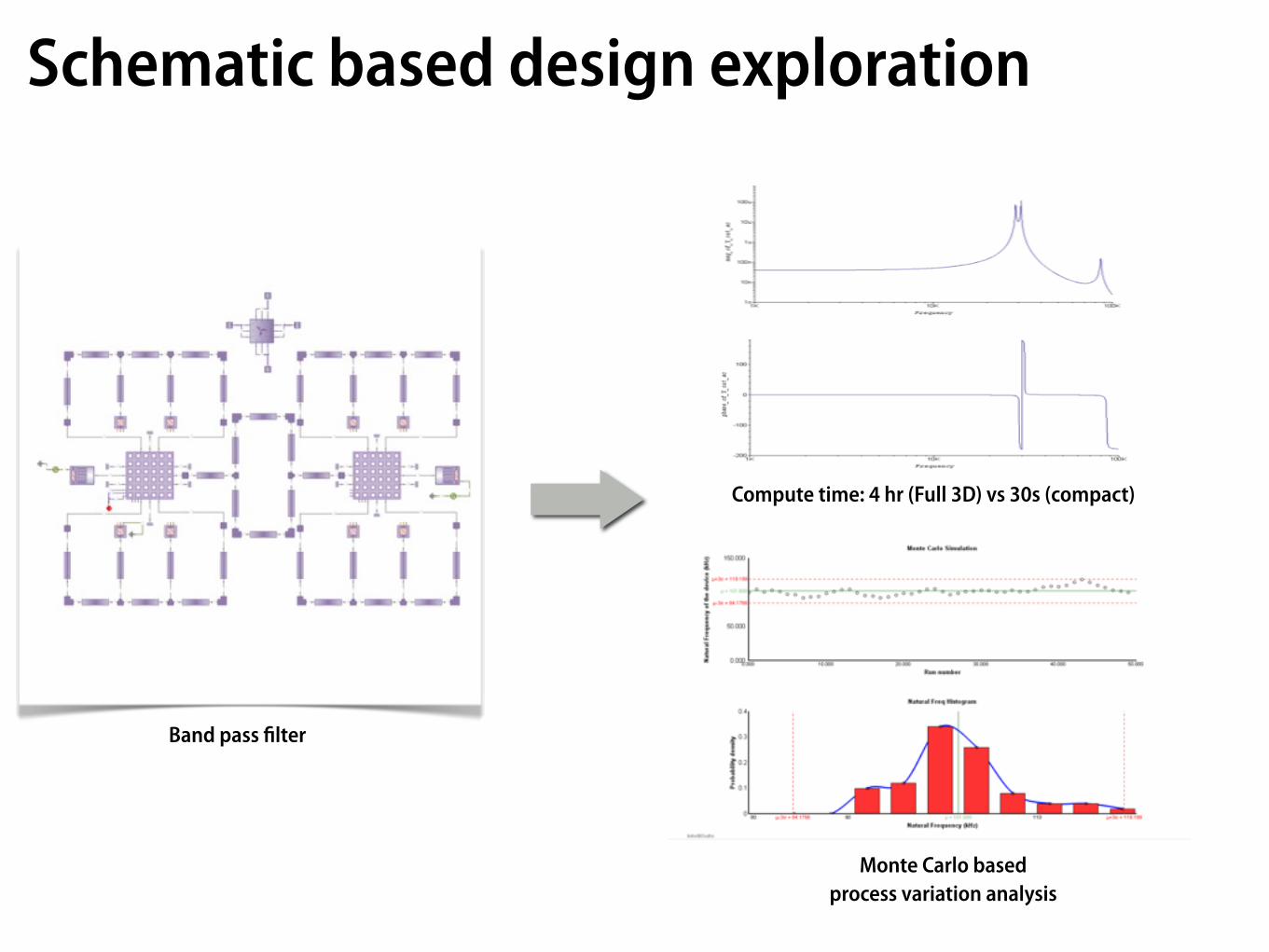
Schematic based design exploration
Compute time: 4 hr (Full 3D) vs 30s (compact)
Band pass filter
Monte Carlo basedprocess variation analysis

Schematic to mask
Attention to detail
Stress relief curves Dimples Comb bumpers Etch compensationfeatures
Automated layout synthesis

Schematic to mesh
Automated Hexahedral Meshing of the Structure
BenefitsSave time100-1000X faster than FEA models.
Design exploration and optimizationQuickly prototype and explore multiple designs
Automated mask and mesh exportEasy transition to next stages in design cycle

Process development

Virtual process traveller

Virtual FabricationCourtesy, Prof Tim Dallas, Texas Tech

Virtual FabricationCourtesy, Prof Tim Dallas, Texas Tech

Virtual FabricationCourtesy, Prof Tim Dallas, Texas Tech

process to model

Cross-SectioningStep by step process visualization
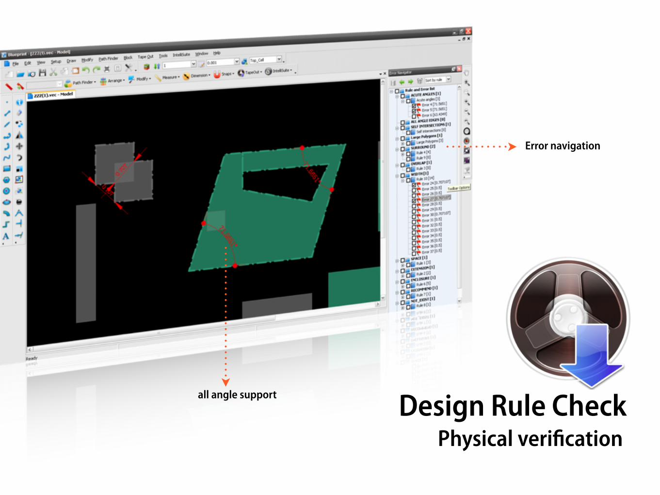
Design Rule CheckPhysical verification
all angle support
Error navigation

Simulate composite MEMS processes
Composite processes, Shikida Mitsuhiro, J. Micromech. Microeng. 14
Combination of multi-step mask transfers, oxide and nitride layers, sacrificial layer deposition and wet etching and DRIE processes.

Validate processes in design
110 um100 min
166 um150 min
225 um200 min
56 um50 min
166.40 um139.62 min
110.93 um95.27 min
226.13 um190.44 min
56.89 um51.27 min
© 20
01 G
esse
lscha
ft fu
r Mikr
oelek
tronik
an-w
endu
ng Ch
emnit
z mbH
.
Measured Modeledvs

The chain of pain… How do you fine tune TSV processes?
Process Engineer

Multiphysics analysis

The chain of pain…
Solid Model Creation
Analysis Model Creation
Geometry Decomposition
Meshing
Mesh Manipulation
Assign Model Parameters
Assemble Simulation Model
Run Simulation
Post Process Results
1%
5%
4%
4%
6%
6%
14%
32%
21%
8%
Packaging EngineerDevice Engineer
Courtesy: Matt Staten, Computing and Modeling Dept, Sandia National Labs
80%
How do you efficiently create MEMS + Package models?Close to 80% of the time spent in mesh creation and manipulation…

1 Click Hex Meshing…

FEM-BEM mesh
Mechanical mesh
Electrostatic mesh

FEM-BEM advantagesBest solver for each physics domainBoundary Element Method (BEM): Electrostatics, Electromagnetics Finite Element Method (FEM): Thermal, Mechanical and ElectromagneticsVolume of Flow (VoF) and Finite Volume (FV): Fluidics, Electrokinetics, Chemical Reactions
Speed and efficiency2-10X Faster than pure FEA formulation
Surface meshing vs volume meshesInternal volumes, air gaps, etc do not need to be meshedEase of meshing, no costly re-meshing during deformation
Ease of convergenceDeal with large deformations, contact and post-contact without convergence issues

MEMS+IC integration

The chain of pain…
MEMS+Package ASIC
ElectroMechanical InteractionPackaging Interaction
Thermal Interaction
?
Electrical EngineerPackaging Engineer Device Engineer
How do you compensate packaging and temperature effects?

System Model Extraction (SME)
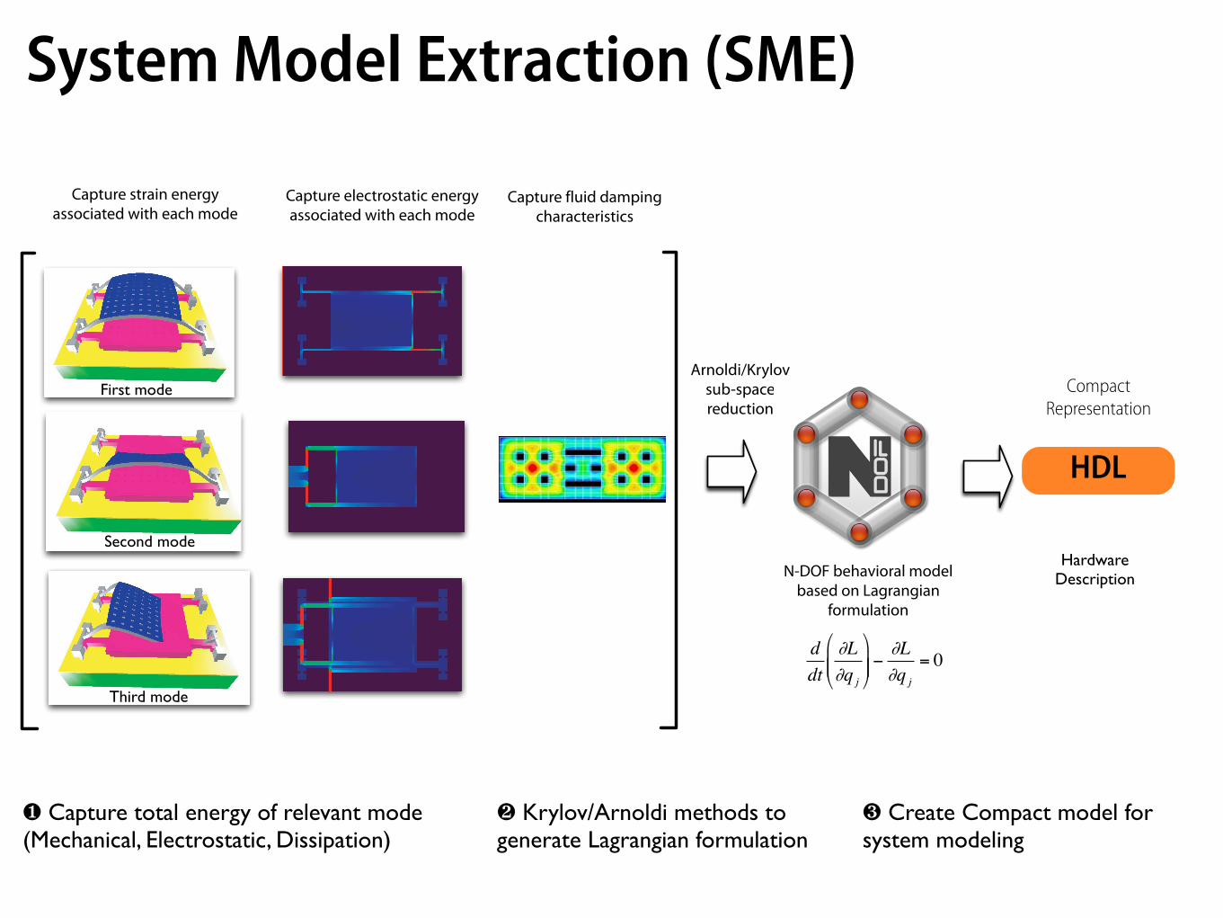
❶ Capture total energy of relevant mode(Mechanical, Electrostatic, Dissipation)
❷ Krylov/Arnoldi methods to generate Lagrangian formulation
❸ Create Compact model for system modeling
System Model Extraction (SME)
First mode
Second mode
Third mode
Capture strain energy associated with each mode
Capture electrostatic energyassociated with each mode
Capture fluid dampingcharacteristics
Arnoldi/Krylov sub-spacereduction
N-DOF behavioral modelbased on Lagrangian
formulation
!
d
dt
"L
"q j
#
$ % %
&
' ( ( )
"L
"q j
= 0
HDL formulation
CompactRepresentation
HardwareDescription
HDL

Final MEMS Device design
Transistor level design(SPICE or other EDA tools)
Gate level design(Cadence/Synopsys/Mentor/Tanner etc)
Design Exploration/Optimization1
2
4
5
Final Layout(L-Edit/Virtuoso/other)
6
Reduced-order Model Extraction3
MEMS-CMOS integrationdesign flow can be based on :
√ VHDL-AMS
√ Verilog-A
√ SPICE netlist
√ Matlab/Simulink .MEX
Integrated design flow for MEMS + IC

Summary
MEMS Design is a collaboration challenge
Behavioral modeling tools assist design exploration
Virtual fabrication tools save time and money in the cleanroom
Automated meshing and FEM-BEM solvers speed up design cycle
Model extraction methods link MEMS/IC development
36

www.intellisense.com
Dziękuję • Спасибо • Ευχαριστώ • Asante Sana • Dankie

![Modeling and Simulation of a CMOS-MEMS Infrared Thermopile ...chanodieck.com/media/publications/Modeling_and... · infrared (IR) spectrophotometry [1]. This scheme requires the integration](https://static.fdocuments.us/doc/165x107/5f085aba7e708231d421987c/modeling-and-simulation-of-a-cmos-mems-infrared-thermopile-infrared-ir-spectrophotometry.jpg)