Analysis and Simulation of Serpentine Suspensions for MEMS Applications€¦ · ·...
4
Analysis and Simulation of Serpentine Suspensions for MEMS Applications M. Bedier 1,2 and Roshdy AbdelRassoul 2 1 KACST-Intel Consortium Center of Excellence in Nano-manufacturing Application (CENA), Riyadh Saudi Arabia 2 Arab Academy for Science, Technology and Maritime Transport (AAST), Alexandria, Egypt Email: [email protected], [email protected] Abstract—In many MEMS devices, the mechanical suspension method usually creates a problem of how it should be suspended versus the design area and structure complexity. Simple designs may be able to keep complexity level down, however they do not usually hit the targeted specifications. Serpentine suspension proves to be very useful in such cases. In this paper, three serpentine suspensions are discussed and analyzed. Mathematical expressions of each serpentine are derived in terms of stiffness. The derived expressions validity was tested with COMSOL simulation, and results show very good agreement between analytical expression and simulation. Index Terms—serpentine, suspension, MEMS, stiffness. I. INTRODUCTION It can be said that the field of micro-electro- mechanical systems (MEMS) was originated by Richard P. Feynman in 1959, when he made the observation: There is plenty of room at the bottom [1]. He was the first one to induce the idea of miniaturization of systems. MEMS can also be defined, as is the integration of mechanical elements, sensors, actuators, and electronics on a common silicon substrate through micro fabrication technology. While the functional elements of MEMS are miniaturized structures, sensors, actuators, and microelectronics, the most notable (and perhaps most interesting) elements are the microsensors and micro- actuators. Microsensors and microactuators are appropriately categorized as transducers, which are defined as devices that convert energy from one form to another [2]. MEMS promises to revolutionize nearly every product category by bringing together silicon-based microelectronics with micromachining technology making possible the realization of complete systems-on- a-chip [3]. There are different types of actuators such as electro- static actuator in which the electrostatic force is created by applying the voltage across the two plates. But in order to have a large deflection or force, the suspensions that are used to carry on the movable plates need to be carefully designed. Serpentines flexures are very useful when low stiffness is required with a limited design space. By Manuscript received July 10, 2013; revised October 23, 2013 adding extra elements (meanders) to the serpentine, the overall stiffness can significantly reduced. In this paper, the stiffness expressions for three different serpentine arrangements are discussed. Analytical expressions are then validated with simulation, and the results show good agreement between analytical expressions and simulation. In Sections II the serpentine suspension is introduced, while in Section III both analytical derivations and simulation are presented. The results and discussions are presented in section IV, and conclusions in section V. II. SERPENTINE DEFINITION AND ANALYSIS The serpentine suspension can be defined by repeated meanders. A single meander consists of two connector beams and two span beams. For the rest of this paper, the width and thickness of each of the connector beams and span beams are kept fixed along each serpentine arrangement. (a) (b) (c) Figure 1. Serpentine arrangements. International Journal of Materials Science and Engineering Vol. 1, No. 2 December 2013 ©2013 Engineering and Technology Publishing 82 doi: 10.12720/ijmse.1.2.82-85
Transcript of Analysis and Simulation of Serpentine Suspensions for MEMS Applications€¦ · ·...

Analysis and Simulation of Serpentine
Suspensions for MEMS Applications
M. Bedier 1,2
and Roshdy AbdelRassoul 2
1KACST-Intel Consortium Center of Excellence in Nano-manufacturing Application (CENA), Riyadh Saudi Arabia
2Arab Academy for Science, Technology and Maritime Transport (AAST), Alexandria, Egypt
Email: [email protected], [email protected]
Abstract—In many MEMS devices, the mechanical
suspension method usually creates a problem of how it
should be suspended versus the design area and structure
complexity. Simple designs may be able to keep complexity
level down, however they do not usually hit the targeted
specifications. Serpentine suspension proves to be very
useful in such cases. In this paper, three serpentine
suspensions are discussed and analyzed. Mathematical
expressions of each serpentine are derived in terms of
stiffness. The derived expressions validity was tested with
COMSOL simulation, and results show very good
agreement between analytical expression and simulation.
Index Terms—serpentine, suspension, MEMS, stiffness.
I. INTRODUCTION
It can be said that the field of micro-electro-
mechanical systems (MEMS) was originated by Richard
P. Feynman in 1959, when he made the observation:
There is plenty of room at the bottom [1]. He was the
first one to induce the idea of miniaturization of systems.
MEMS can also be defined, as is the integration of
mechanical elements, sensors, actuators, and electronics
on a common silicon substrate through micro fabrication
technology. While the functional elements of MEMS are
miniaturized structures, sensors, actuators, and
microelectronics, the most notable (and perhaps most
interesting) elements are the microsensors and micro-
actuators. Microsensors and microactuators are
appropriately categorized as transducers, which are
defined as devices that convert energy from one form to
another [2].
MEMS promises to revolutionize nearly every product
category by bringing together silicon-based
microelectronics with micromachining technology
making possible the realization of complete systems-on-
a-chip [3]. There are different types of actuators such as
electro- static actuator in which the electrostatic force is
created by applying the voltage across the two plates.
But in order to have a large deflection or force, the
suspensions that are used to carry on the movable plates
need to be carefully designed.
Serpentines flexures are very useful when low
stiffness is required with a limited design space. By
Manuscript received July 10, 2013; revised October 23, 2013
adding extra elements (meanders) to the serpentine, the
overall stiffness can significantly reduced.
In this paper, the stiffness expressions for three
different serpentine arrangements are discussed.
Analytical expressions are then validated with simulation,
and the results show good agreement between analytical
expressions and simulation.
In Sections II the serpentine suspension is introduced,
while in Section III both analytical derivations and
simulation are presented. The results and discussions are
presented in section IV, and conclusions in section V.
II. SERPENTINE DEFINITION AND ANALYSIS
The serpentine suspension can be defined by repeated
meanders. A single meander consists of two connector
beams and two span beams. For the rest of this paper, the
width and thickness of each of the connector beams and
span beams are kept fixed along each serpentine
arrangement.
(a)
(b)
(c)
Figure 1. Serpentine arrangements.
International Journal of Materials Science and Engineering Vol. 1, No. 2 December 2013
©2013 Engineering and Technology Publishing 82doi: 10.12720/ijmse.1.2.82-85

A. Serpentine 1
Figure 2. Serpentine 1 free-body diagram.
The first serpentine arrangement is shown in Fig. 1(a).
The free-guided connector beam is connected with a
span beam of the same length as the rest of the span
beams. The connector beam is repeated n of times while
the span beams are (n-1) times. As mentioned before, the
serpentine is referred to by: the number of meanders or
either the number of connector beams. The connector
beam is of length (a) while the span beams are of length
(b). The width of the span beams is (wa), while the width
of connector beam is (wb). The thickness is assumed to
be the same for both connector and span beams (t). The
free-body diagram for calculation of the z-direction
spring constant is given in Fig. 2. Force, moment and
torque are examined at each beam segment using Energy
method [4]-[5]. The resulting moment and torsion
expressions for the connector beams are as follows,
, 0 ( ( 1) )a j zM M f i a
(1)
0
1 ( 1), ( )
2
i
a zT j T f b
(2)
where, Ma,i and Ta,i are the moment and torsion of the ith
connector beam respectively. The bending moment and
torsion for the span beams are,
, 0b j zM T f (3)
, 0b j zT M jf a (4)
where, Mb,j and Tb,j are the moment and torsion of the jth
span beam respectively.
The total strain energy can be expressed by,
2 2
, ,
01 ,
2 2
, ,
01 ,
( ) 2 2
( )2 2
n a a i a i
i x a a
jb b i b i
j x b b
M TU d
EI GJ
M Td
EI GJ
n 1
(5)
Assuming a free-guided end with a rotational angles
equal to zero, thus,
0
0
0U
M
(6)
0
0
0U
T
(7)
The stiffness can be deduced from the deflection in the
z-direction,
z
z
U
f
(8)
A MATLAB routine is used to deduce stiffness
expressions for various meander numbers.
B. Serpentine 2
Another case of serpentine having equal number of
span beams and connector beams–Fig. 1(b)-is analyzed
in the following subsection. The free-body diagram is
shown in Fig. 3. This serpentine arrangement is used for
the proposed designs as it employees the best use of
design area and allow the lowest stiffness possible in that
area. Applying the Energy method analysis, the bending
moment and torsion for connector beams are the same as
Eq. (1) and Eq. (2), respectively. Similarly, the bending
moment and torsion for span beams are the same as Eq.
(3) and Eq. (4), however, the strain energy should
include the extra span beam added in Serpentine 2, as
follows,
2 2
, ,
01 ,
2 2
, ,
01 ,
( ) 2 2
( )2 2
n a a i a i
i x a a
jb b i b i
j x b b
M TU d
EI GJ
M Td
EI GJ
n
(9)
The total Serpentine 2 stiffness for various number of
connector beams is derived.
Figure 3. Serpentine 2 free-body diagram.
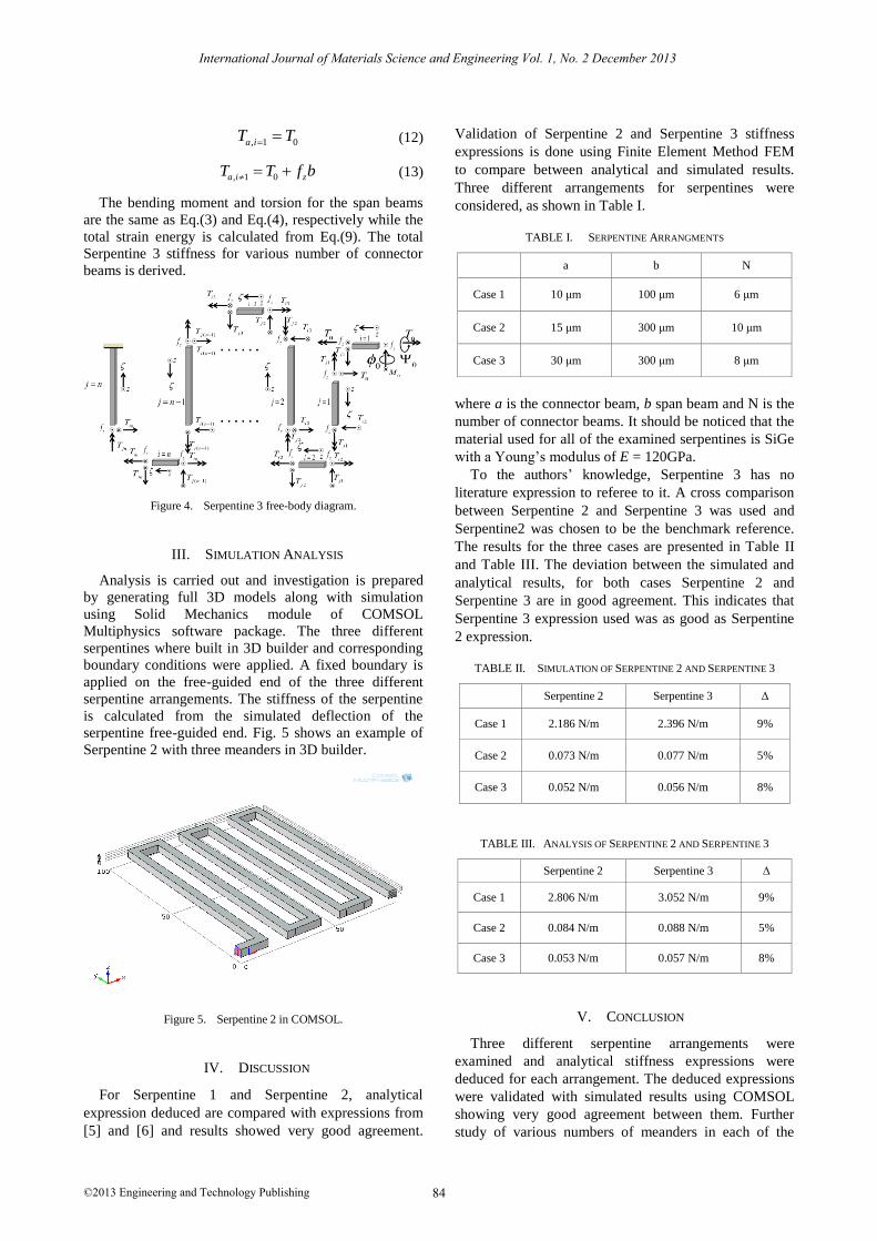
C. Serpentine 3
A third serpentine arrangement is analyzed that has
similar geometry to Serpentine 2 but with half-ended
beam as shown in Fig. 1(c), while Fig. 4 shows the free
body diagram.
The bending moment and torsion for the connector
beams are,
, 1 0a i zM M f (10)
, 1 0 ( ( 1) )a i zM M f i a
(11)
International Journal of Materials Science and Engineering Vol. 1, No. 2 December 2013
©2013 Engineering and Technology Publishing 83
, 1 0a iT T (12)
, 1 0a i zT T f b (13)
The bending moment and torsion for the span beams
are the same as Eq.(3) and Eq.(4), respectively while the
total strain energy is calculated from Eq.(9). The total
Serpentine 3 stiffness for various number of connector
beams is derived.
Figure 4. Serpentine 3 free-body diagram.
III. SIMULATION ANALYSIS
Analysis is carried out and investigation is prepared
by generating full 3D models along with simulation
using Solid Mechanics module of COMSOL
Multiphysics software package. The three different
serpentines where built in 3D builder and corresponding
boundary conditions were applied. A fixed boundary is
applied on the free-guided end of the three different
serpentine arrangements. The stiffness of the serpentine
is calculated from the simulated deflection of the
serpentine free-guided end. Fig. 5 shows an example of
Serpentine 2 with three meanders in 3D builder.
Figure 5. Serpentine 2 in COMSOL.
IV. DISCUSSION
For Serpentine 1 and Serpentine 2, analytical
expression deduced are compared with expressions from
[5] and [6] and results showed very good agreement.
Validation of Serpentine 2 and Serpentine 3 stiffness
expressions is done using Finite Element Method FEM
to compare between analytical and simulated results.
Three different arrangements for serpentines were
considered, as shown in Table I.
TABLE I. SERPENTINE ARRANGMENTS
a b N
Case 1 10 μm 100 μm 6 μm
Case 2 15 μm 300 μm 10 μm
Case 3 30 μm 300 μm 8 μm
where a is the connector beam, b span beam and N is the
number of connector beams. It should be noticed that the
material used for all of the examined serpentines is SiGe
with a Young’s modulus of E = 120GPa.
To the authors’ knowledge, Serpentine 3 has no
literature expression to referee to it. A cross comparison
between Serpentine 2 and Serpentine 3 was used and
Serpentine2 was chosen to be the benchmark reference.
The results for the three cases are presented in Table II
and Table III. The deviation between the simulated and
analytical results, for both cases Serpentine 2 and
Serpentine 3 are in good agreement. This indicates that
Serpentine 3 expression used was as good as Serpentine
2 expression.
TABLE II. SIMULATION OF SERPENTINE 2 AND SERPENTINE 3
Serpentine 2 Serpentine 3 Δ
Case 1 2.186 N/m 2.396 N/m 9%
Case 2 0.073 N/m 0.077 N/m 5%
Case 3 0.052 N/m 0.056 N/m 8%
TABLE III. ANALYSIS OF SERPENTINE 2 AND SERPENTINE 3
Serpentine 2 Serpentine 3 Δ
Case 1 2.806 N/m 3.052 N/m 9%
Case 2 0.084 N/m 0.088 N/m 5%
Case 3 0.053 N/m 0.057 N/m 8%
V. CONCLUSION
Three different serpentine arrangements were
examined and analytical stiffness expressions were
deduced for each arrangement. The deduced expressions
were validated with simulated results using COMSOL
showing very good agreement between them. Further
study of various numbers of meanders in each of the
International Journal of Materials Science and Engineering Vol. 1, No. 2 December 2013
©2013 Engineering and Technology Publishing 84
three serpentines should define the regions of accuracy
of the deduced expressions.
ACKNOWLEDGMENT
This work was supported by a grant from KACST
(King Abdul-Aziz City of Science and Technology)-Intel
Corporation Consortium Center of Excellence in Nano-
manufacturing Applications (CENA), Saudi Arabia, with
host-site imec, Leuven, Belgium.
REFERENCES
[1] J. W. Judy and R. S. Muller, “Magnetic microactuation of
torsional polysilicon structures,” in Proc. International
Conference on Solid-State Sensors and Actuators, 1995.
[2] H. A. Tilmans, “MEMS components for wireless
communications,” in Proc. 16th Eurpopen Conference on Solid-State Transducers, 2004.
[3] M. Gad-ELHak, The MEMS Handbook, Mechanical Engineering Handbook Series. CRC, 2002.
[4] G. M. Rebeiz, RF MEMS: Theory, Design and Technology, Wiley,
2003. [5] G. Fedder, “Simulation of micromechanical systems,” PhD. thesis,
University of California, Berkeley, 1994. [6] D. Peroulis and L. P. B. Katehi, “Electrostatically-tunable analog
RF MEMS varactors with measured capacitance range of 300%,”
in Proc. IEEE MTT-S International Microwave Symposium Digest, Philadelphia, PA, USA, 8-13 June 2003, pp. 1793-1796.
Mohammed A. Bedier was born in Alexandria, Egypt in
1986. He received both B.Sc. and M.Sc. degrees in electronics and communications engineering (with honors)
from the Arab Academy for Science, Technology and
Maritimes (AAST), Alexandria, Egypt, in 2008 and 2012 respectively. Form the period of 2008 until 2011 he
worked as a teaching assistant at AAST. He received a CENA Intel-KACST grant to conduct research at imec, Leuven, Belgium, in the
period of September 2011 until March 2013. During his research at
imec he received his Master’s degree in electronics and communication in the area of RF-MEMS design of variable capacitors. His current
research interests included RF-MEMS design and modeling and medical image processing.
Roshdy A. Abdel Rassoul received the B.Sc. degree (with Honors) and the M.Sc. degree, both in Electrical
Engineering from Alexandria University, Egypt, and
received the Ph.D. degree in Electrical Engineering from SMU, Dallas, TX, in 1981.He was an Assistant Professor
in Louisiana State University, USA, Southern University, USA, and Mansoura University, Egypt, and an Associate Professor in
King Saud University, Saudi Arabia, and Mansoura University, Egypt,
and is now a Professor in the Electronics and Communication Engineering Department, at the Arab Academy for Science &
Technology, Alexandria, Egypt. He has published more than 70 technical papers.
International Journal of Materials Science and Engineering Vol. 1, No. 2 December 2013
©2013 Engineering and Technology Publishing 85