Model XMT868 - Ultrasonic Flow Meters, Water level, Water ... · June 2003 Proc e ss Control I...
179
Model XMT868 Programming Manual (One- and Two-Channel)
Transcript of Model XMT868 - Ultrasonic Flow Meters, Water level, Water ... · June 2003 Proc e ss Control I...

Model XMT868
Programming Manual
(One- and Two-Channel)

June 2003
Process Control Instruments
Model XMT868
Ultrasonic Flow Transmitter for
Liquids (1- & 2-Channel)
Programming Manual 910-171PB

iii
June 2003
Warranty Each instrument manufactured by GE Panametrics is warranted to be free from defects in material and workmanship. Liability under this warranty is limited to restoring the instrument to normal operation or replacing the instrument, at the sole discretion of GE Panametrics. Fuses and batteries are specifically excluded from any liability. This warranty is effective from the date of delivery to the original purchaser. If GE Panametrics determines that the equipment was defective, the warranty period is:
• one year for general electronic failures of the instrument
• one year for mechanical failures of the transducers
If GE Panametrics determines that the equipment was damaged by misuse, improper installation, the use of unauthorized replacement parts, or operating conditions outside the guidelines specified by GE Panametrics, the repairs are not covered under this warranty.
The warranties set forth herein are exclusive and are in lieu ofall other warranties whether statutory, express or implied(including warranties or merchantability and fitness for aparticular purpose, and warranties arising from course ofdealing or usage or trade).
Return Policy If a GE Panametrics instrument malfunctions within the warranty period, the following procedure must be completed:
1. Notify GE Panametrics, giving full details of the problem, and provide the model number and serial number of the instrument. If the nature of the problem indicates the need for factory service, GE Panametrics will issue a RETURN AUTHORIZATION NUMBER (RAN), and shipping instructions for the return of the instrument to a service center will be provided.
2. If GE Panametrics instructs you to send your instrument to a service center, it must be shipped prepaid to the authorized repair station indicated in the shipping instructions.
3. Upon receipt, GE Panametrics will evaluate the instrument to determine the cause of the malfunction.
Then, one of the following courses of action will then be taken:
• If the damage is covered under the terms of the warranty, the instrument will be repaired at no cost to the owner and returned.
• If GE Panametrics determines that the damage is not covered under the terms of the warranty, or if the warranty has expired, an estimate for the cost of the repairs at standard rates will be provided. Upon receipt of the owner’s approval to proceed, the instrument will be repaired and returned.

June 2003
Table of Contents
Chapter 1: Programming Site Data
Introduction . . . . . . . . . . . . . . . . . . . . . . . . . . . . . . . . . . . . . . . . . . . . . . . . . . . . . . . . . . . . . . . . . 1-1Programming Methods. . . . . . . . . . . . . . . . . . . . . . . . . . . . . . . . . . . . . . . . . . . . . . . . . . . . . . . . . 1-1Using the RCCU . . . . . . . . . . . . . . . . . . . . . . . . . . . . . . . . . . . . . . . . . . . . . . . . . . . . . . . . . . . . . 1-2
Communications Failure . . . . . . . . . . . . . . . . . . . . . . . . . . . . . . . . . . . . . . . . . . . . . . . . . . . . 1-6The User Program . . . . . . . . . . . . . . . . . . . . . . . . . . . . . . . . . . . . . . . . . . . . . . . . . . . . . . . . . . . . 1-6
Accessing the User Program . . . . . . . . . . . . . . . . . . . . . . . . . . . . . . . . . . . . . . . . . . . . . . . . . 1-7The PROG Menu . . . . . . . . . . . . . . . . . . . . . . . . . . . . . . . . . . . . . . . . . . . . . . . . . . . . . . . . . . . . 1-10The CHx Menu. . . . . . . . . . . . . . . . . . . . . . . . . . . . . . . . . . . . . . . . . . . . . . . . . . . . . . . . . . . . . . 1-11
The ACTIV Sub-Menu . . . . . . . . . . . . . . . . . . . . . . . . . . . . . . . . . . . . . . . . . . . . . . . . . . . . 1-11The CHx-SYSTM Sub-Menu . . . . . . . . . . . . . . . . . . . . . . . . . . . . . . . . . . . . . . . . . . . . . . . 1-12The PIPE Sub-Menu . . . . . . . . . . . . . . . . . . . . . . . . . . . . . . . . . . . . . . . . . . . . . . . . . . . . . . 1-20The I/O Sub-Menu. . . . . . . . . . . . . . . . . . . . . . . . . . . . . . . . . . . . . . . . . . . . . . . . . . . . . . . . 1-31The Setup Sub-Menu . . . . . . . . . . . . . . . . . . . . . . . . . . . . . . . . . . . . . . . . . . . . . . . . . . . . . . 1-34
The GLOBL Menu. . . . . . . . . . . . . . . . . . . . . . . . . . . . . . . . . . . . . . . . . . . . . . . . . . . . . . . . . . . 1-51The GLOBL-SYSTM Sub-Menu . . . . . . . . . . . . . . . . . . . . . . . . . . . . . . . . . . . . . . . . . . . . 1-52The I/O Sub-Menu. . . . . . . . . . . . . . . . . . . . . . . . . . . . . . . . . . . . . . . . . . . . . . . . . . . . . . . . 1-55The COMM Sub-Menu . . . . . . . . . . . . . . . . . . . . . . . . . . . . . . . . . . . . . . . . . . . . . . . . . . . . 1-77
Exiting the User Program. . . . . . . . . . . . . . . . . . . . . . . . . . . . . . . . . . . . . . . . . . . . . . . . . . . . . . 1-82
Chapter 2: Displaying Data
Introduction . . . . . . . . . . . . . . . . . . . . . . . . . . . . . . . . . . . . . . . . . . . . . . . . . . . . . . . . . . . . . . . . . 2-1Displaying Data with the LCD. . . . . . . . . . . . . . . . . . . . . . . . . . . . . . . . . . . . . . . . . . . . . . . . . . . 2-1
Adjusting LCD Contrast and Brightness . . . . . . . . . . . . . . . . . . . . . . . . . . . . . . . . . . . . . . . . 2-1Programming the LCD . . . . . . . . . . . . . . . . . . . . . . . . . . . . . . . . . . . . . . . . . . . . . . . . . . . . . 2-2
Displaying Data with the RCCU . . . . . . . . . . . . . . . . . . . . . . . . . . . . . . . . . . . . . . . . . . . . . . . . . 2-6Displaying Data on a Computer Terminal . . . . . . . . . . . . . . . . . . . . . . . . . . . . . . . . . . . . . . . . . . 2-9
iv
June 2003
Table of Contents (cont.)
Chapter 3: Logging Data
Introduction . . . . . . . . . . . . . . . . . . . . . . . . . . . . . . . . . . . . . . . . . . . . . . . . . . . . . . . . . . . . . . . . . .3-1The Data Logging Option Card . . . . . . . . . . . . . . . . . . . . . . . . . . . . . . . . . . . . . . . . . . . . . . . . . . .3-1Accessing the XMT868 LOG Menu . . . . . . . . . . . . . . . . . . . . . . . . . . . . . . . . . . . . . . . . . . . . . . .3-1Setting Up a Standard Log. . . . . . . . . . . . . . . . . . . . . . . . . . . . . . . . . . . . . . . . . . . . . . . . . . . . . . .3-2
Programming the Log Channels . . . . . . . . . . . . . . . . . . . . . . . . . . . . . . . . . . . . . . . . . . . . . . .3-3STARTTIME Prompt . . . . . . . . . . . . . . . . . . . . . . . . . . . . . . . . . . . . . . . . . . . . . . . . . . . . . . .3-6START DATE Prompt . . . . . . . . . . . . . . . . . . . . . . . . . . . . . . . . . . . . . . . . . . . . . . . . . . . . . .3-7END TIME Prompt. . . . . . . . . . . . . . . . . . . . . . . . . . . . . . . . . . . . . . . . . . . . . . . . . . . . . . . . .3-8END DATE Prompt . . . . . . . . . . . . . . . . . . . . . . . . . . . . . . . . . . . . . . . . . . . . . . . . . . . . . . . .3-9DURATION Prompt . . . . . . . . . . . . . . . . . . . . . . . . . . . . . . . . . . . . . . . . . . . . . . . . . . . . . . .3-10LOG TIME Prompt. . . . . . . . . . . . . . . . . . . . . . . . . . . . . . . . . . . . . . . . . . . . . . . . . . . . . . . .3-10TIME INCREMENT Prompt . . . . . . . . . . . . . . . . . . . . . . . . . . . . . . . . . . . . . . . . . . . . . . . .3-11
Setting Up an Error Log . . . . . . . . . . . . . . . . . . . . . . . . . . . . . . . . . . . . . . . . . . . . . . . . . . . . . . .3-12Programming the Log Channels . . . . . . . . . . . . . . . . . . . . . . . . . . . . . . . . . . . . . . . . . . . . . .3-13STARTTIME Prompt . . . . . . . . . . . . . . . . . . . . . . . . . . . . . . . . . . . . . . . . . . . . . . . . . . . . . .3-16START DATE Prompt . . . . . . . . . . . . . . . . . . . . . . . . . . . . . . . . . . . . . . . . . . . . . . . . . . . . .3-17
Checking the XMT868 Memory . . . . . . . . . . . . . . . . . . . . . . . . . . . . . . . . . . . . . . . . . . . . . . . . .3-18Stopping a Log. . . . . . . . . . . . . . . . . . . . . . . . . . . . . . . . . . . . . . . . . . . . . . . . . . . . . . . . . . . . . . .3-19Uploading a Log File to the RCCU . . . . . . . . . . . . . . . . . . . . . . . . . . . . . . . . . . . . . . . . . . . . . . .3-19
If memory is OK . . . . . . . . . . . . . . . . . . . . . . . . . . . . . . . . . . . . . . . . . . . . . . . . . . . . . . . . . .3-21If memory is low . . . . . . . . . . . . . . . . . . . . . . . . . . . . . . . . . . . . . . . . . . . . . . . . . . . . . . . . . .3-21
Reading a Log File with the RCCU. . . . . . . . . . . . . . . . . . . . . . . . . . . . . . . . . . . . . . . . . . . . . . .3-23Log File Structure . . . . . . . . . . . . . . . . . . . . . . . . . . . . . . . . . . . . . . . . . . . . . . . . . . . . . . . . .3-23Selecting a Log to Read . . . . . . . . . . . . . . . . . . . . . . . . . . . . . . . . . . . . . . . . . . . . . . . . . . . .3-25Navigating Through the Log Screens . . . . . . . . . . . . . . . . . . . . . . . . . . . . . . . . . . . . . . . . . .3-26
Chapter 4: Printing Data
Data Types for Printing . . . . . . . . . . . . . . . . . . . . . . . . . . . . . . . . . . . . . . . . . . . . . . . . . . . . . . . . .4-1
Chapter 5: Clearing Data
Introduction . . . . . . . . . . . . . . . . . . . . . . . . . . . . . . . . . . . . . . . . . . . . . . . . . . . . . . . . . . . . . . . . . .5-1Clearing the RCCU’s Memory . . . . . . . . . . . . . . . . . . . . . . . . . . . . . . . . . . . . . . . . . . . . . . . . . . .5-1
Clearing a Site File . . . . . . . . . . . . . . . . . . . . . . . . . . . . . . . . . . . . . . . . . . . . . . . . . . . . . . . . .5-2Clearing Log Files. . . . . . . . . . . . . . . . . . . . . . . . . . . . . . . . . . . . . . . . . . . . . . . . . . . . . . . . . .5-3
Clearing the XMT868’s Memory . . . . . . . . . . . . . . . . . . . . . . . . . . . . . . . . . . . . . . . . . . . . . . . . .5-4Clearing Site Data . . . . . . . . . . . . . . . . . . . . . . . . . . . . . . . . . . . . . . . . . . . . . . . . . . . . . . . . . .5-5Clearing Log Files. . . . . . . . . . . . . . . . . . . . . . . . . . . . . . . . . . . . . . . . . . . . . . . . . . . . . . . . . .5-5Clearing the Totalizers . . . . . . . . . . . . . . . . . . . . . . . . . . . . . . . . . . . . . . . . . . . . . . . . . . . . . .5-6
v

June 2003
Table of Contents (cont.)
Appendix A: Menu Maps
The CHx-ACTIV, SYSTM and PIPE with Energy OFF Menus . . . . . . . . . . . . . . . . . . . . . . . . . A-1The CHx-ACTIV, SYSTM and PIPE with Energy ON Menus . . . . . . . . . . . . . . . . . . . . . . . . . . A-2The CHx-I/O and SETUP Menus . . . . . . . . . . . . . . . . . . . . . . . . . . . . . . . . . . . . . . . . . . . . . . . . A-3The Display, GLOBL-SYSTM, SLOT0 and COMM Menus . . . . . . . . . . . . . . . . . . . . . . . . . . . A-4The GLOBL-I/O-ERROR and OPTN Menus . . . . . . . . . . . . . . . . . . . . . . . . . . . . . . . . . . . . . . . A-5The PROG-LOG Menu . . . . . . . . . . . . . . . . . . . . . . . . . . . . . . . . . . . . . . . . . . . . . . . . . . . . . . . . A-6The LOG and CLEAR Menus . . . . . . . . . . . . . . . . . . . . . . . . . . . . . . . . . . . . . . . . . . . . . . . . . . . A-7
Appendix B: Data Records
Available Option Cards . . . . . . . . . . . . . . . . . . . . . . . . . . . . . . . . . . . . . . . . . . . . . . . . . . . . . . . . B-1Option Cards Installed . . . . . . . . . . . . . . . . . . . . . . . . . . . . . . . . . . . . . . . . . . . . . . . . . . . . . . . . . B-2Site Data . . . . . . . . . . . . . . . . . . . . . . . . . . . . . . . . . . . . . . . . . . . . . . . . . . . . . . . . . . . . . . . . . . . . B-3
Appendix C: Instrument Data Manager
The CHx-STATUS, SYSTEM and INPUT/OUTPUT Menu Maps. . . . . . . . . . . . . . . . . . . . . . . C-1The CHx-PIPE Menu Map. . . . . . . . . . . . . . . . . . . . . . . . . . . . . . . . . . . . . . . . . . . . . . . . . . . . . . C-2The CHx-SETUP Menu Map. . . . . . . . . . . . . . . . . . . . . . . . . . . . . . . . . . . . . . . . . . . . . . . . . . . . C-3The GLOBAL-SYSTEM, I/O-ERROR HANDLING, SLOT0, DISPLAY and COMM PORT Menu Maps. . . . . . . . . . . . . . . . . . . . . . . . . . . . . . . . . . . . . . . C-4The GLOBL-I/O-OPTIONS-SLOT1 Menu Map. . . . . . . . . . . . . . . . . . . . . . . . . . . . . . . . . . . . . C-5The PAUSE MEASUREMENT and FILE Menu Maps . . . . . . . . . . . . . . . . . . . . . . . . . . . . . . . C-6The LOG EDIT Menu Map . . . . . . . . . . . . . . . . . . . . . . . . . . . . . . . . . . . . . . . . . . . . . . . . . . . . . C-7
vi

Chapter 1

Programming Site Data
Introduction . . . . . . . . . . . . . . . . . . . . . . . . . . . . . . . . . . . . . . . . . . .1-1
Programming Methods . . . . . . . . . . . . . . . . . . . . . . . . . . . . . . . . . .1-1
Using the RCCU . . . . . . . . . . . . . . . . . . . . . . . . . . . . . . . . . . . . . . . .1-2
The User Program . . . . . . . . . . . . . . . . . . . . . . . . . . . . . . . . . . . . . .1-6
The PROG Menu. . . . . . . . . . . . . . . . . . . . . . . . . . . . . . . . . . . . . . .1-10
The CHx Menu . . . . . . . . . . . . . . . . . . . . . . . . . . . . . . . . . . . . . . . . 1-11
The GLOBL Menu. . . . . . . . . . . . . . . . . . . . . . . . . . . . . . . . . . . . . .1-51
Exiting the User Program . . . . . . . . . . . . . . . . . . . . . . . . . . . . . . .1-82
June 2003
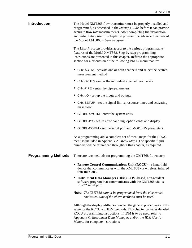
Introduction The Model XMT868 flow transmitter must be properly installed and programmed, as described in the Startup Guide, before it can provide accurate flow rate measurements. After completing the installation and initial setup, use this chapter to program the advanced features of the Model XMT868’s User Program.
The User Program provides access to the various programmable features of the Model XMT868. Step-by-step programming instructions are presented in this chapter. Refer to the appropriate section for a discussion of the following PROG menu features:
• CHx-ACTIV - activate one or both channels and select the desired measurement method
• CHx-SYSTM - enter the individual channel parameters
• CHx-PIPE - enter the pipe parameters
• CHx-I/O - set up the inputs and outputs
• CHx-SETUP - set the signal limits, response times and activating mass flow.
• GLOBL-SYSTM - enter the system units
• GLOBL-I/O - set up error handling, option cards and display
• GLOBL-COMM - set the serial port and MODBUS parameters
As a programming aid, a complete set of menu maps for the PROG menu is included in Appendix A, Menu Maps. The specific figure numbers will be referenced throughout this chapter, as required.
Programming Methods There are two methods for programming the XMT868 flowmeter:
• Remote Control Communications Unit (RCCU) - a hand-held device that communicates with the XMT868 via wireless, infrared transmissions.
• Instrument Data Manager (IDM) - a PC-based, non-resident software program that communicates with the XMT868 via its RS232 serial port.
Note: The XMT868 cannot be programmed from the electronics enclosure. One of the above methods must be used.
Although the displays differ somewhat, the general procedures are the same for the RCCU and IDM methods. This chapter provides detailed RCCU programming instructions. If IDM is to be used, refer to Appendix C, Instrument Data Manager, and/or the IDM User’s Manual for complete instructions.
Programming Site Data 1-1
June 2003
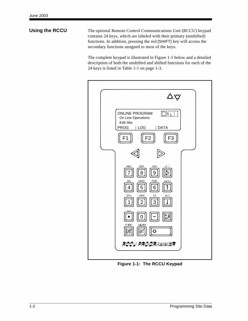
Using the RCCU The optional Remote Control Communications Unit (RCCU) keypad contains 24 keys, which are labeled with their primary (unshifted) functions. In addition, pressing the red [SHIFT] key will access the secondary functions assigned to most of the keys.
The complete keypad is illustrated in Figure 1-1 below and a detailed description of both the unshifted and shifted functions for each of the 24 keys is listed in Table 1-1 on page 1-3.
Figure 1-1: The RCCU Keypad
7ABC
8DEF
9GHI OFF
654
PQRMNOJKL SEND
YZ
3
VWXSTU
1 2
RCV
0PRINT MENU
F2 F3F1
PROG LOG DATA
ONLINE PROGRAMOn Line OperationsEdit Site
S L
1-2 Programming Site Data

June 2003
Table 1-1: The RCCU Key Functions
Key Unshifted Function Shifted Function
Software Function Keys - press to select the functions displayed directly above them in the display window.
None
Shift Key - press to access the shifted func-tions of the other keys; the light indicates that shifted mode is active. Press once to shift next entry only, press twice to lock shift mode, press again to unlock shift mode.
None
Left Arrow Key - press to scroll through menu options; when entering text, moves the cursor one space to the left and deletes character in that space.
None
Right Arrow Key - press to scroll through menu options; when entering text, deletes rest of entry and moves cursor one space to the right.
None
Up Arrow Key - in programming mode, press to return to the previous prompt.
SEND - not yet available
Down Arrow Key - in programming mode, press to move to the next prompt.
RCV - not yet available
Zero Key - use to enter a number 0. None
One Key - press to enter a number 1. Press 1 time to enter the letter SPress 2 times to enter the letter TPress 3 times to enter the letter U
Two Key - press to enter a number 2. Press 1 time to enter the letter VPress 2 times to enter the letter WPress 3 times to enter the letter X
Three Key - press to enter a number 3. Press 1 time to enter the letter YPress 2 times to enter the letter Z
Four Key - press to enter a number 4. Press 1 time to enter the letter JPress 2 times to enter the letter KPress 3 times to enter the letter L
0
1
2
3
4
Programming Site Data 1-3

June 2003
Five Key - press to enter a number 5. Press 1 time to enter the letter MPress 2 times to enter the letter NPress 3 times to enter the letter O
Six Key - press to enter a number 6. Press 1 time to enter the letter PPress 2 times to enter the letter QPress 3 times to enter the letter R
Seven Key - press to enter a number 7. Press 1 time to enter the letter APress 2 times to enter the letter BPress 3 times to enter the letter C
Eight Key - press to enter a number 8. Press 1 time to enter the letter DPress 2 times to enter the letter EPress 3 times to enter the letter F
Nine Key - press to enter a number 9. Press 1 time to enter the letter GPress 2 times to enter the letter HPress 3 times to enter the letter I
Clear Key - press to enter the CLEAR menu. See Chapter 5, Clearing Data, for details.
None
Exit Key - press to leave the current menu, saving entered values, and return to the next higher menu.
PRNT - not yet available
Enter Key - press to accept the currently displayed value or text.
MENU - not yet available
ON Key - press once to power up the RCCU. Hold down to turn on the display backlight.
OFF - press to power down the RCCU
Decimal Point Key - press to enter a deci-mal point during numeric entry.
Space - press to enter a space
Minus Key - press to enter a minus sign or a dash.
None
Table 1-1: The RCCU Key Functions (Continued)
Key Unshifted Function Shifted Function
5
6
7
8
9
CLR
EXIT
ENT
ON
1-4 Programming Site Data

June 2003
Using the RCCU (cont.) To energize the RCCU, press the [ON] key on its keypad. The RCCU’s LCD display, which consists of 4 lines x 20 characters, will be activated. See Figure 1-1 on page 1-2 for the layout of the RCCU keypad and display.
Note: For instructions on replacing the RCCU’s battery, refer to Chapter 4, Parts Replacement, in the Service Manual.
For reliable RCCU communications, the infrared receiver in the window of the XMT868 should have a clear line of sight to the RCCU and should be located within 8 ft. (2.5 m) of the RCCU with an angle of incidence of no more than 15°.
Immediately upon activation, the RCCU will perform its normal startup routine. This results in a display of the GE Panametrics logo, followed by these informational displays:
The RCCU is now ready for operation.
GE Panametrics Inc.
--RCCU--
Remote Control
Communications Unit
Software Revision “XXX” represents the current software version.RCCU XXX
F1 F2 F3
IDM MENU START GGGG When the startup routine has been completed, this IDM Menu Start display appears.
IDM MENU
previous selection appears here
SYSTEM ONLINE OFFLNE
F1 F2 F3
Programming Site Data 1-5

June 2003
Communications Failure If an attempt to communicate with the XMT868 does not result in a proper connection with the RCCU, and error message such as the following appears:
Make sure:
• the RCCU battery is not weak;
• the windows on both the RCCU and the XMT868 are clean;
• the transmission distance does not exceed 8 ft. (2.5 m);
• the angle of incidence does not exceed 15°; and
• there is an unobstructed line of sight between the two devices.
Then, carefully aim the RCCU and try again. If this fails to resolve the problem, see Chapter 4, Parts Replacement, in the Service Manual for instructions on RCCU battery replacement. If a fresh battery does not solve the problem, contact GE Panametrics for help.
The User Program Use the RCCU keypad (see Table 1-1 on page 1-3) to navigate through the PROG menu of the User Program. The menu map may be followed in sequence, or the [↑] and [↓] keys may be used to scroll through the prompt screens. The [ ] key may be used to delete the last alphanumeric character that was entered from the keypad.
Note: Be sure to record all the programming data entered in this chapter in Appendix B, Data Records.
Programming of the ACTIV, SYSTM, and PIPE sub-menus of the CHx menu and the GLOBL-SYSTM menu are required for basic operation of the Model XMT868. Failure to accurately enter all of the necessary information will result in unreliable flow rate data. Therefore, be sure to complete at least the sections of this chapter pertaining to those three sub-menus.
Note: Because it is so essential, instructions for programming the ACTIV, SYSTM, PIPE and GLOBL-SYSTM sub-menus are also included in the Startup Guide. If that programming has already been completed, skip those sections in this chapter.
8C or Communicating At this display, press [F1] to try again or press [F2] to quit.NO Packet Rcvd ce2
Retry/Abort Commlink
RETRY ABORT
F1 F2 F3
1-6 Programming Site Data

June 2003
The User Program (cont.)
Except for the three sub-menus noted above, it is not necessary to program the Model XMT868 flowmeter in any particular order. Therefore, the sections of this chapter need not be completed in sequence. Enter the user program as described in Accessing the User Program below and proceed immediately to any section of interest.
Accessing the User Program
To access the XMT868’s User Program, the RCCU must be pointed directly at the receiver in the window on the electronics enclosure whenever data is being sent or received (see Figure 1-2 below). The XMT868 has various lights to indicate its communication status:
• The green light in the window glows continuously to indicate that the XMT868 is receiving power.
• The red light should glow for more than two seconds whenever a signal from the RCCU is initiated. If the red light blinks repeatedly, the XMT868 is not receiving the RCCU signal correctly.
• The Send/Receive lights on the RCCU blink once to indicate the sending/receiving of a signal.
Note: If the red (Fault) light blinks once or flickers briefly, a flow fault is indicated. This is unrelated to the RCCU, and the problem must be resolved by referring to Chapters 2 and 3, Error Codes and Diagnostics, in the Service Manual.
Figure 1-2: XMT868 Front Window
R
SA
UO VR I
NE
P
EN
OS SUT
NS
OI
H
OT
DN
O
NEOP
W
GR
DISE
NELI E
E
RCV
XMT868TXPWRFAULTTX
Receiver
Green Power Light
Optional Display
Red Fault Light
SendSend
Programming Site Data 1-7

June 2003
Accessing the User Program (cont.)
IMPORTANT: Always keep the RCCU pointed directly at the XMT868 while communicating with the meter.
If the operation was aborted, the RCCU resets to the main menu. Otherwise, proceed to the next display.
IDM MENU START GGGG At this display, press [F2] to select ONLINE.IDM MENU
previous selection appears here
SYSTEM ONLINE OFFLNE
F1 F2 F3
Uploading Basic Press the [F1] key to select RCV and begin communications, or press [F2] to select CANCEL and abort the operation.
Target System Info.
Press RCV Key...
RCV CANCEL
F1 F2 F3
Communicating... This display shows the status of the communication attempt.PRESS EXIT to ESCAPE
50 Percent Complete
F1 F2 F3
When the connection is established, this message appears briefly and is then replaced by the following display.
TARGET METER ID
THIS IS AN XMT
F1 F2 F3
1-8 Programming Site Data

June 2003
Accessing the User Program (cont.)
Note: The arrow in the upper right corner of the display indicates that additional options are available. These are accessed by pressing the [ ] or [ ] key.
Proceed to the appropriate section for further instructions on using the PROG menu.
ONLINE PROGRAM GGG| The XMT868 is now ready to be programmed. To begin programming, press [F1] to select PROG.
On Line Operations
Edit Site
PROG LOG DATA
ONLINE PROGRAM GGG| (These additional options are accessed by pressing the [ ] and/or [ ] keys.)
On Line Operations
Edit Site
SITE CLEAR TEST
F1 F2 F3
Programming Site Data 1-9

June 2003
The PROG Menu After pressing [ENT] or one of the [Fx] keys on the RCCU, the following screen appears:
IMPORTANT: Be sure to record all programming data in Appendix B, Data Records.
IMPORTANT: Wait for the RCCU and the XMT868 to communicate and for the next prompt to appear before pressing any other keys. Although the above display always appears, it will not be specifically shown in this manual after every selection entry.
Note: In this manual, only the programming of Channel 1 will be described. To program Channel 2 of a 2-Channel meter, simply repeat the same procedures presented for Channel 1.
Based on the selection made at the above prompt, proceed to the appropriate section for instructions.
Communicating... This display shows the status of the communication attempt.PRESS EXIT to ESCAPE
50 Percent Complete
F1 F2 F3
GGG| Press [F1] to enter the PROG menu.PROG CHOICES
SITE EDIT MENU
PROG CAL PAUSE
GGG| (These additional options, which only appears if a data logging option card is installed in Slot 2, are accessed by pressing the [ ] or [ ] key.)
PROG CHOICES
SITE EDIT MENU
LOG FILE
F1 F2 F3
GGGG Press the [Fx] under the desired option to select it. (Note that the CH2 option does not appear for a 1-Channel meter.)
PROGRAM
Channel 1
CH1 CH2 GLOBL
F1 F2 F3
1-10 Programming Site Data
June 2003
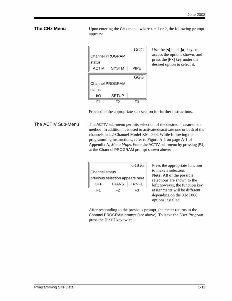
The CHx Menu Upon entering the CHx menu, where x = 1 or 2, the following prompt appears:
Proceed to the appropriate sub-section for further instructions.
The ACTIV Sub-Menu The ACTIV sub-menu permits selection of the desired measurement method. In addition, it is used to activate/deactivate one or both of the channels in a 2-Channel Model XMT868. While following the programming instructions, refer to Figure A-1 on page A-1 of Appendix A, Menu Maps. Enter the ACTIV sub-menu by pressing [F1] at the Channel PROGRAM prompt shown above:
After responding to the previous prompt, the meter returns to the Channel PROGRAM prompt (see above). To leave the User Program, press the [EXIT] key twice.
GGG| Use the [ ] and [ ] keys to access the options shown, and press the [Fx] key under the desired option to select it.
Channel PROGRAM
status
ACTIV SYSTM PIPE
GGG|
Channel PROGRAM
status
I/O SETUP
F1 F2 F3
GGGG Press the appropriate function to make a selection. Note: All of the possible selections are shown to the left; however, the function key assignments will be different depending on the XMT868 options installed.
Channel status
previous selection appears here
OFF TRANS TRNFL
F1 F2 F3
Programming Site Data 1-11

June 2003
The CHx-SYSTM Sub-Menu
While following the programming instructions, refer to Figure A-1 on page A-1 of Appendix A, Menu Maps. Enter the SYSTM sub-menu by pressing [F2] at the Channel PROGRAM prompt on page 1-11:
Refer to Figure A-1 on page A-1 if you selected OFF or refer to Figure A-2 on page A-2 if you selected ON of Appendix A, Menu Maps.
The abbreviations and definitions of all the available volumetric and totalizer units are shown in Table 1-2 on page 1-13.
Key in the desired CHANNEL LABEL (up to 9 characters) and press [ENT].
CHANNEL LABEL
current label appears here
F1 F2 F3
Key in the desired CHANNEL MESSAGE (up to 21 characters) and press [ENT]. (For a 1-Channel meter, this prompt is called SITE MESSAGE.)
CHANNEL MESSAGE
current message appears here
F1 F2 F3
For the ENERGY OPTION, press [F1] for OFF, or [F2] for ON.
ENERGY OPTION
current message appears here
OFF ON
F1 F2 F3
GGG| Press [F1]-[F3] to select the desired volumetric units for the flow rate display.
VOLUMETRIC UNITS
current selection appears here
GAL/S GAL/M GAL/H
GGG| Use the [ ] and [ ] keys to access the additional choices shown.
VOLUMETRIC UNITS
current selection appears here
MGD ft3/s ft3/m
F1 F2 F3
1-12 Programming Site Data

June 2003
The CHx-SYSTM Sub-Menu (cont.) Table 1-2: Available Volumetric Units
English Metric
GAL/S = gallons/second L/S = liters/second
GAL/M = gallons/minute L/M = liters/minute
GAL/H = gallons/hour ML/D = million liters/day
MGD = million gallons/day m^3/s = cubic meters/second
ft3/s = cubic feet/second m^3/m = cubic meters/minute
ft3/m = cubic feet/minute m^3/h = cubic meters/hour
ft3/h = cubic feet/hour m^3/d = cubic meters/day
Mf3/d = millions cubic feet/day Mm^3/d = million cubic meters/day
BBL/S = barrels/second BBL/S = barrels/second
BBL/M = barrels/minute BBL/M = barrels/minute
BBL/D = barrels/day BBL/H = barrels/hour
MBBL/D = millions barrels/day MBL/D = million barrels/day
A-I/S = acre-inches/second
A-I/M = acre-inches/minute
A-I/H = acre-inches/hour
A-I/D = acre-inches/day
A-F/S = acre-feet/second
A-F/M = acre-feet/minute
A-F/H = acre-feet/hour
A-F/D = acre-feet/day
GGG| Press [F1]-[F3] to select the desired number of digits to the right of the decimal point in the volumetric flow rate display.
VOL DECIMAL DIGITS
current setting appears here
0 1 2
GGG| Use the [ ] and [ ] keys to access the additional choice shown.
VOL DECIMAL DIGITS
current setting appears here
3
F1 F2 F3
Programming Site Data 1-13
June 2003
The CHx-SYSTM Sub-Menu (cont.)
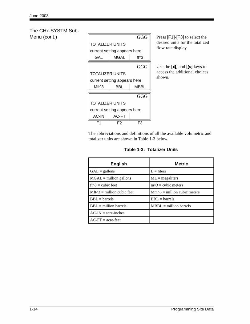
The abbreviations and definitions of all the available volumetric and totalizer units are shown in Table 1-3 below.
Table 1-3: Totalizer Units
GGG| Press [F1]-[F3] to select the desired units for the totalized flow rate display.
TOTALIZER UNITS
current setting appears here
GAL MGAL ft^3
GGG| Use the [ ] and [ ] keys to access the additional choices shown.
TOTALIZER UNITS
current setting appears here
Mft^3 BBL MBBL
GGG|
TOTALIZER UNITS
current setting appears here
AC-IN AC-FT
F1 F2 F3
English Metric
GAL = gallons L = liters
MGAL = million gallons ML = megaliters
ft^3 = cubic feet m^3 = cubic meters
Mft^3 = million cubic feet Mm^3 = million cubic meters
BBL = barrels BBL = barrels
BBL = million barrels MBBL = million barrels
AC-IN = acre-inches
AC-FT = acre-feet
1-14 Programming Site Data

June 2003
The CHx-SYSTM Sub-Menu (cont.)
Do one of the following:
• MASS FLOW is ON - proceed to the MASS FLOW prompt below.
• MASS FLOW is OFF and
• ENERGY OPTION is ON - proceed to the POWER prompt on page 1-18.
• ENERGY OPTION is OFF - the meter returns to the Channel PROGRAM prompt shown on page 1-11. To leave the User Program, press the [EXIT] key twice.
Note: The prompt above shows English units, as an example. If Metric units were specified, these appear instead.
GGG| Press [F1]-[F3] to select the desired number of digits to the right of the decimal point in the totalized flow rate display.
TOTAL DECIMAL DIGITS
current setting appears here
0 1 2
GGG| Use the [ ] and [ ] keys to access the additional choice shown.
TOTAL DECIMAL DIGITS
current setting appears here
3
F1 F2 F3
GGG| Press [F1]-[F3] to select the desired mass flow units for flow rate display.
MASS FLOW
current setting appears here
LB KLB MMLB
GGG| Use the [ ] and [ ] keys to access the additional choice shown.
MASS FLOW
current setting appears here
TONS
F1 F2 F3
Programming Site Data 1-15

June 2003
The CHx-SYSTM Sub-Menu (cont.)
The abbreviations and definitions of the available mass flow units are shown in Table 1-4 below. The choices shown in the above prompt are determined by the selection made at the SYSTEM UNITS prompt.
Table 1-4: Available Mass Flow Units
English Metric
LB = Pounds KG = Kilograms
KLB = Thousands of LB TONNE = Metric Tons (1000 KG)
MMLB = Millions of LB
TONS = Tons (2000 LB)
GGG| Press [F1]-[F3] to select the desired time units for the mass flow rate display.
MASS FLOW TIME
current setting appears here
/SEC /MIN /HR
GGG| Use the [ ] and [ ] keys to access the additional choice shown.
MASS FLOW TIME
current setting appears here
/DAY
F1 F2 F3
GGG| Press [F1]-[F3] to select the desired number of digits to the right of the decimal point in the mass flow rate display.
MDOT DECIMAL DIGITS
current setting appears here
0 1 2
GGG| Use the [ ] and [ ] keys to access the additional choice shown.
MDOT DECIMAL DIGITS
current setting appears here
3
F1 F2 F3
1-16 Programming Site Data

June 2003
The CHx-SYSTM Sub-Menu (cont.)
Note: The prompt above shows English units, as an example. If Metric units were specified, these appear instead.
The available mass flow units are shown in Table 1-4 on page 1-16. The choices shown in the above prompt are determined by the selection made at the SYSTEM UNITS prompt.
GGG| Press [F1]-[F3] to select the desired units for the totalized mass flow rate display.
MASS TOTALS
current setting appears here
LB KLB MMLB
GGG| Use the [ ] and [ ] keys to access the additional choice shown.
MASS TOTALS
current setting appears here
TONS
F1 F2 F3
GGG| Press [F1]-[F3] to select the desired number of digits to the right of the decimal point in the totalized mass flow display.
MASS DECIMAL DIGITS
current setting appears here
0 1 2
GGG| Use the [ ] and [ ] keys to access the additional choice shown.
MASS DECIMAL DIGITS
current setting appears here
3
F1 F2 F3
Programming Site Data 1-17
June 2003
The CHx-SYSTM Sub-Menu (cont.)
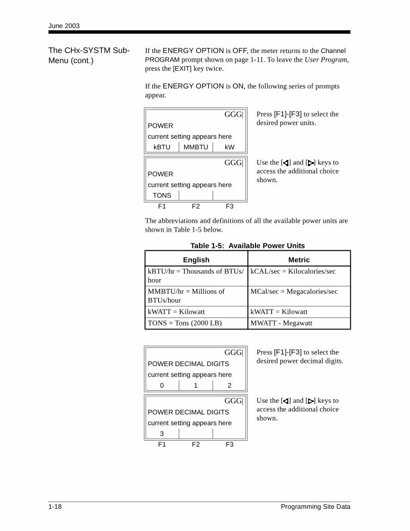
If the ENERGY OPTION is OFF, the meter returns to the Channel PROGRAM prompt shown on page 1-11. To leave the User Program, press the [EXIT] key twice.
If the ENERGY OPTION is ON, the following series of prompts appear.
The abbreviations and definitions of all the available power units are shown in Table 1-5 below.
GGG| Press [F1]-[F3] to select the desired power units.POWER
current setting appears here
kBTU MMBTU kW
GGG| Use the [ ] and [ ] keys to access the additional choice shown.
POWER
current setting appears here
TONS
F1 F2 F3
Table 1-5: Available Power Units
English Metric
kBTU/hr = Thousands of BTUs/hour
kCAL/sec = Kilocalories/sec
MMBTU/hr = Millions of BTUs/hour
MCal/sec = Megacalories/sec
kWATT = Kilowatt kWATT = Kilowatt
TONS = Tons (2000 LB) MWATT - Megawatt
GGG| Press [F1]-[F3] to select the desired power decimal digits.POWER DECIMAL DIGITS
current setting appears here
0 1 2
GGG| Use the [ ] and [ ] keys to access the additional choice shown.
POWER DECIMAL DIGITS
current setting appears here
3
F1 F2 F3
1-18 Programming Site Data
June 2003
The CHx-SYSTM Sub-Menu (cont.)
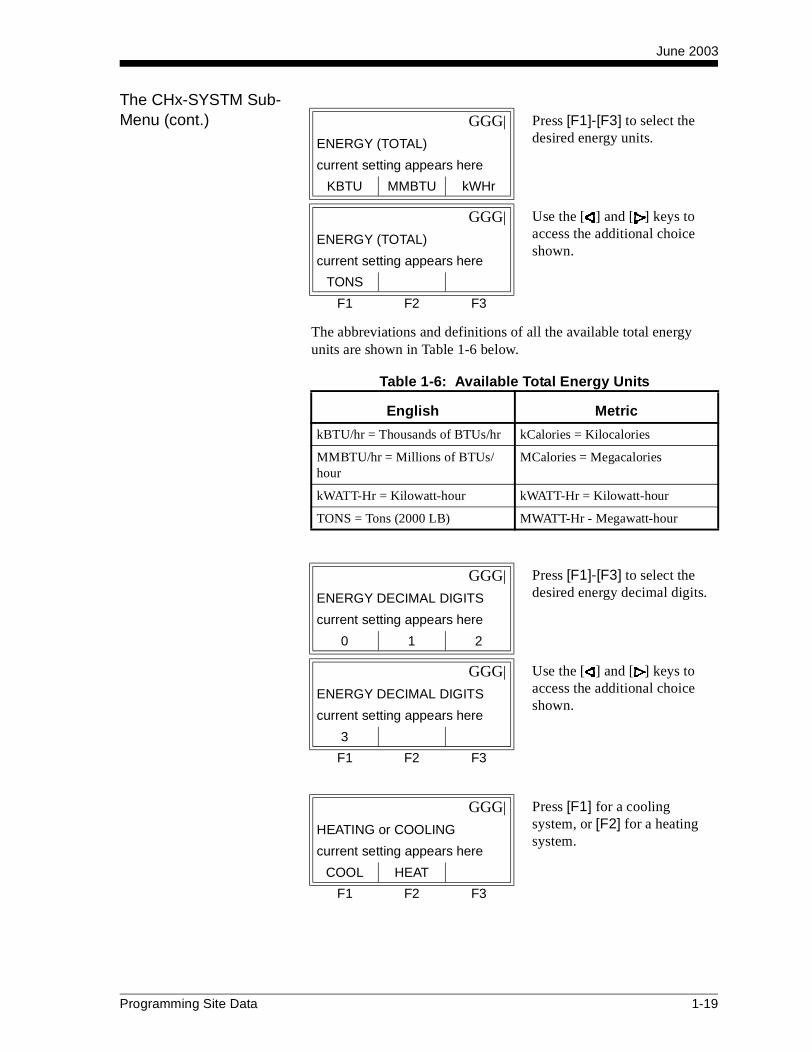
The abbreviations and definitions of all the available total energy units are shown in Table 1-6 below.
GGG| Press [F1]-[F3] to select the desired energy units.ENERGY (TOTAL)
current setting appears here
KBTU MMBTU kWHr
GGG| Use the [ ] and [ ] keys to access the additional choice shown.
ENERGY (TOTAL)
current setting appears here
TONS
F1 F2 F3
Table 1-6: Available Total Energy Units
English Metric
kBTU/hr = Thousands of BTUs/hr kCalories = Kilocalories
MMBTU/hr = Millions of BTUs/hour
MCalories = Megacalories
kWATT-Hr = Kilowatt-hour kWATT-Hr = Kilowatt-hour
TONS = Tons (2000 LB) MWATT-Hr - Megawatt-hour
GGG| Press [F1]-[F3] to select the desired energy decimal digits.ENERGY DECIMAL DIGITS
current setting appears here
0 1 2
GGG| Use the [ ] and [ ] keys to access the additional choice shown.
ENERGY DECIMAL DIGITS
current setting appears here
3
F1 F2 F3
GGG| Press [F1] for a cooling system, or [F2] for a heating system.
HEATING or COOLING
current setting appears here
COOL HEAT
F1 F2 F3
Programming Site Data 1-19

June 2003
The CHx-SYSTM Sub-Menu (cont.)
The display now returns you to the top menu, ACTIV, SYSTM, PIPE, I/O and SETUP.
The PIPE Sub-Menu Enter the transducer and pipe parameters via the PIPE sub-menu. While following the programming instructions, refer to Figure A-1 on page A-1 of Appendix A, Menu Maps. Enter the PIPE sub-menu by pressing [F3] at the Channel PROGRAM prompt shown on page 1-11.
IMPORTANT: Special transducers, which have no engraved number on the head, are rarely used. Examine the transducer head carefully for a number.
To program the XMT868 for use with the type of transducer being used, do one of the following:
• Special transducers - proceed to the section below.
• Standard wetted transducers - proceed to the PIPE OD prompt on page 1-23.
• Standard clamp-on transducers - proceed to the PIPE MATERIAL prompt on page 1-22.
Special Transducers The next three prompts apply only to special transducers. If a standard clamp-on transducer is being used, skip ahead to the PIPE OD prompt on page 1-23.
GGG| This prompt asks whether you want to measure flow at the point of return (where the liquid exits) or at the point of supply (where the liquid enters). Press [F1] for return, or [F2] for supply.
FLOW MEASUREMENT
current setting appears here
RTN SPPLY
F1 F2 F3
For a standard transducer, press [F1], enter the number engraved on the transducer head, and press [ENT]. If there is no number engraved on the transducer head, press [F2] and then press [ENT].
TRANSDUCER NUMBER
number appears here
STD SPEC
F1 F2 F3
GGGG Assign a number between 91 and 99 to the specialtransducer and press [ENT].
SPECIAL TRANSDUCER #
number appears here
F1 F2 F3
1-20 Programming Site Data

June 2003
Special Transducers (cont.)
IMPORTANT: The frequency is required to transmit an excitation voltage at the transducer’s natural frequency.
Tw is the time required for the transducer signal to travel through the transducer and its cable. This time delay must be subtracted from the transit times of the upstream and downstream transducers to ensure an accurate measurement.
The following two prompts only appear if special clamp-on transducers are being used. If special wetted transducers are being used, proceed to PIPE OD on page 1-23.
GGGG Press [F1]-[F3] to select the wedge type.WEDGE TYPE
current setting appears here
RAYL SHEAR WETTD
F1 F2 F3
GGG| Press [F1]-[F3] to select the frequency of the special transducer.
FREQUENCY
current setting appears here
500k 1MHz 2MHz
GGG| Use the [ ] and [ ] keys to access the additional choices shown.
FREQUENCY
current setting appears here
5MHz
F1 F2 F3
GGGG Enter the special transducer time delay value supplied by GE Panametrics and press [ENT].
Tw
_______ usec
F1 F2 F3
GGGG Enter the wedge angle of the transducer and press [ENT].WEDGE ANGLE
current value appears here
F1 F2 F3
Programming Site Data 1-21
June 2003
Special Transducers (cont.)
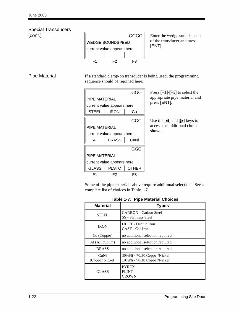
Pipe Material If a standard clamp-on transducer is being used, the programming sequence should be rejoined here.
Some of the pipe materials above require additional selections. See a complete list of choices in Table 1-7.
GGGG Enter the wedge sound speed of the transducer and press [ENT].
WEDGE SOUNDSPEED
current value appears here
F1 F2 F3
GGG| Press [F1]-[F3] to select the appropriate pipe material and press [ENT].
PIPE MATERIAL
current value appears here
STEEL IRON Cu
GGG| Use the [ ] and [ ] keys to access the additional choice shown.
PIPE MATERIAL
current value appears here
Al BRASS CuNi
GGG|
PIPE MATERIAL
current value appears here
GLASS PLSTC OTHER
F1 F2 F3
Table 1-7: Pipe Material Choices
Material Types
STEELCARBON - Carbon SteelSS - Stainless Steel
IRONDUCT - Ductile IronCAST - Cas Iron
Cu (Copper) no additional selection required
Al (Aluminum) no additional selection required
BRASS no additional selection required
CuNi(Copper Nickel)
30%Ni - 70/30 Copper/Nickel10%Ni - 90/10 Copper/Nickel
GLASSPYREXFLINTCROWN
1-22 Programming Site Data

June 2003
Pipe OD The programming sequence should be rejoined here for all transducers.
Note: The prompt above shows English units, as an example. Refer to Table 1-8 for a list of English and metric units.
Obtain the required information by measuring either the pipe outside diameter (OD) or circumference at the transducer installation site. The data may also be obtained from standard pipe size tables found in Sound Speeds and Pipe Size Data manual (914-004).
PLSTC (Plastic)
NYLONPLOYE - PolyethylenePOLYP - PolypropylenePVC - Polyvinyl ChlorideACRYL - Acrylic
OTHER
Enter the soundspeed of the pipe material and press [ENT]. If the soundspeed is unknown, refer to the Sound Speeds and Pipe Size Data manual (914-004).
Table 1-7: Pipe Material ChoicesMaterial Types
GGG| Press [F1]-[F3] to select the appropriate units and enter the known pipe outside diameter or circumference and press [ENT].
PIPE OD
current value appears here
inch feet in/PI
GGG| Use the [ ] and [ ] keys to access the additional choice shown.
PIPE OD
current value appears here
ft/PI
F1 F2 F3
Table 1-8: Available Pipe OD Units
English Metric
inch = pipe OD in inches mm = pipe OD in millimeters
feet = pipe OD in feet m = pipe OD in meters
in/PI = pipe circumference in inches
mm/PI = pipe circumference in millimeters
ft/PI = pipe circumference in feet
m/PI = pipe circumference in meters
Pipe Material (cont.)
Programming Site Data 1-23

June 2003
Pipe OD (cont.)
If the pipe wall thickness is not available, look up the value in a table of standard pipe size data which can be found in Sound Speeds and Pipe Size Data manual (914-004).
Proceed with one of the following:
• All wetted transducers - proceed to the following prompt, PATH LENGTH below.
• All clamp-on transducers - proceed to LINING on page 1-25.
Path Length
Note: If a spoolpiece was ordered with the meter, the transducer signal path length (P) and the transducer signal axial length (L) are engraved on the flowcell and/or are included in the documentation supplied with the meter. For on-site transducer installations, refer to Appendix C, Measuring P and L Dimensions, in the Startup Guide for instructions.
The next series of prompts differ depending on the measurement mode:
• For Transit-Time mode - proceed to AXIAL LENGTH L below.
• For TransFlection mode - proceed to TRANSDUCER ANGLE on the next page.
Axial Length L
Proceed to TRACKING WINDOWS on page 1-26.
GGGG Enter the known thickness of the pipe wall and press [ENT].PIPE WALL
_______ in (mm)
F1 F2 F3
GGGG Press [F1] or [F2] to select the desired units. Then, enter the path length of the ultrasonic signal and press [ENT].
PATH LENGTH P
current value appears here
inch feet
F1 F2 F3
GGGG Press [F1] or [F2] to select the desired units. Then, enter the axial length of the ultrasonicsignal and press [ENT].
AXIAL LENGTH L
current value appears here
inch feet
F1 F2 F3
1-24 Programming Site Data
June 2003
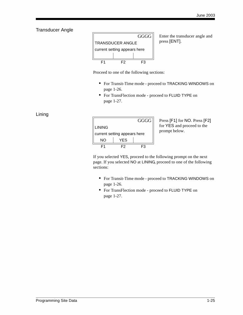
Transducer Angle
Proceed to one of the following sections:
• For Transit-Time mode - proceed to TRACKING WINDOWS on page 1-26.
• For TransFlection mode - proceed to FLUID TYPE onpage 1-27.
Lining
If you selected YES, proceed to the following prompt on the next page. If you selected NO at LINING, proceed to one of the following sections:
• For Transit-Time mode - proceed to TRACKING WINDOWS on page 1-26.
• For TransFlection mode - proceed to FLUID TYPE on page 1-27.
GGGG Enter the transducer angle and press [ENT].TRANSDUCER ANGLE
current setting appears here
F1 F2 F3
GGGG Press [F1] for NO. Press [F2] for YES and proceed to the prompt below.
LINING
current setting appears here
NO YES
F1 F2 F3
Programming Site Data 1-25

June 2003
Lining (cont.)
Proceed to one of the following sections:
• For Transit-Time mode - proceed to TRACKING WINDOWS below.
• For TransFlection mode - proceed to FLUID TYPE on the following page.
Tracking Windows
GGGG Press [F1]-[F3] to select the desired lining material.LINING MATERIAL
current setting appears here
TAR PYREX ASBES
GGGG Use the [ ] and [ ] keys to access the additional choices shown.
LINING MATERIAL
current setting appears here
MORTR RUBBR TEFLN
GGGG If OTHER is selected, enter the lining sound speed, press [ENT]; then enter the lining thickness and press [ENT].
LINING MATERIAL
current setting appears here
OTHER
F1 F2 F3
GGGG Press [F1] for NO. Press [F2] for YES.TRACKING WINDOWS?
current setting appears here
NO YES
F1 F2 F3
1-26 Programming Site Data

June 2003
Fluid Type
The selections for fluid type vary depending on whether:
• the ENERGY OPTION is ON or OFF; and
• the TRACKING WINDOW is enabled or disabled.
Refer to Table 1-9 below if ENERGY OPTION is OFF, or refer to Table 1-10 on the next page if ENERGY OPTION is ON.
Note: Some of the fluid types may require additional selections as shown in the following tables.
Table 1-9: Fluid Types for ENERGY OFF
GGGG Use the [ ] and [ ] keys to access the additional choices. Then, press [F1]-[F3] to select the desired fluid type.
FLUID TYPE
current setting appears here
XXXXX XXXXX XXXXX
F1 F2 F3
Tracking Windows =
NOAdditional Selections YES
Additional Selections
WATER
Select NORML or SEA and press [ENT]. If NORML is selected, enter Water Temperature and press [ENT].
W100
No additional selections required.
OILSelect LUBE or CRUDE and press [ENT].
W260No additional selections required.
METHNo additional selections required.
OILNo additional selections required.
ETH
Enter the Fluid Sound-speed and press [ENT].
OTHER
Enter the Minimum Soundspeed and press [ENT]. Then enter the Maximum Soundspeed and press [ENT].
LN2No additional selections required.
FREONNo additional selections required.
OTHEREnter the fluid sound-speed and press [ENT].
Programming Site Data 1-27

June 2003
Fluid Type (cont.)
Reynolds Correction
• If OFF is selected, enter the Calibration Factor and press [ENT]. Then, proceed to one of the following sections:
• For Clamp-on Transducers -
• using Transit-time mode - proceed to NUMBER OF TRAVERSES on the next page.
• using TransFlection mode - proceed to DEPTH OF REFLECTOR on page 1-30.
• For Wetted Transducers - the display now takes you back to the top menu, ACTIV, SYSTM, PIPE, I/O, SETUP. At this point, you can proceed programming in this sub-menu as desired. To leave the Channel PROGRAM sub-menu, press the [EXIT] key on the RCCU keypad. To complete setting up the meter, you must enter data in the GLOBL-SYSTM sub-menu as described on page 1-52.
• If ACTIV is selected, proceed to KV INPUT SELECTION on the next page.
Table 1-10: Fluid Types for ENERGY ONTracking Windows =
NOAdditional Selections YES
Additional Selections
WATEREnter the Water Temperature and press [ENT].
W260No additional selections required.
MIXED
Enter the Fluid Sound-speed and press [ENT]. Then enter the Percentage of Water and press [ENT].
MIXED
Enter the Percentage of Water and press [ENT].
OTHER
Enter the Fluid Sound-speed and press [ENT].
OTHER
Enter the Minimum Soundspeed and press [ENT]. Then enter the Maximum Sound-speed and press [ENT].
GGGG Press [F1] or [F2] to select the Reynolds Correction status.REYNOLDS CORRECTION
current selection appears here
OFF ACTIV
F1 F2 F3
1-28 Programming Site Data

June 2003
KV Input Selection
If TABLE is selected, enter the Calibration Factor and press [ENT].
If STATC is selected, enter the Kinematic Viscosity and press [ENT]. Then enter the Calibration Factor and press [ENT].
Proceed to one of the following sections:
• For Clamp-on Transducers -
• using Transit-time mode - proceed to the NUMBER OF TRAVERSES prompt below.
• using TransFlection mode - proceed to DEPTH OF REFLECTOR prompt on the next page.
• For Wetted Transducers - the display now takes you back to the top menu, ACTIV, SYSTM, PIPE, I/O, SETUP. At this point, you can proceed programming in this sub-menu as desired. To leave the Channel PROGRAM sub-menu, press the [EXIT] key on the RCCU keypad. To complete setting up the meter, you must enter data in the GLOBL-SYSTM sub-menu as described on page 1-52.
Number of Traverses
GGGG Press [F1] or [F2] to select TABLE or STATC.KV INPUT SELECTION
current selection appears here
TABLE STATC
F1 F2 F3
GGG| Press [F1]-[F3] to select the appropriate number of traverses.
NUMBER OF TRAVERSES
current value appears here
1(Z) 2(V) 3
GGG| Use the [ ] and [ ] keys to access the additional choice shown.
NUMBER OF TRAVERSES
current value appears here
4 5
F1 F2 F3
Programming Site Data 1-29

June 2003
Transducer Spacing
The display now takes you back to the top menu, ACTIV, SYSTM, PIPE, I/O, SETUP. At this point, you can proceed programming in this sub-menu as desired. To leave the Channel PROGRAM sub-menu, press the [EXIT] key on the RCCU keypad. To complete setting up the meter, you must enter data in the GLOBL-SYSTM sub-menu as described on page 1-52.
Depth of Reflector
The Depth of Reflector specifies where in the pipe the flowmeter will look for the reflected transducer signal. The default value is 50%, which places the measurement location at the center of the pipe. This setting is optimal for most applications; however, you may want to decrease this value for larger pipes to improve signal strength. When you decrease this setting, the measurement location moves closer to the wall of the pipe, decreasing the path length and reducing signal attenuation.
Note: GE Panametrics recommends activating the Reynolds Correction Factor when the Depth of Reflector is set to 50%. The Reynolds Correction Factor should be deactivated when the Depth of Reflector is set to any other value.
The display now takes you back to the top menu, ACTIV, SYSTM, PIPE, I/O, SETUP. At this point, you can proceed programming in this sub-menu as desired. To leave the Channel PROGRAM sub-menu, press the [EXIT] key on the RCCU keypad. To complete setting up the meter, you must enter data in the GLOBL-SYSTM sub-menu as described on page 1-55.
GGGG Enter the value for the transducer spacing and press [ENT].
TRANSDUCER SPACING
____ in (mm)
F1 F2 F3
GGGG Enter the value for the Depth of Reflector and press [ENT].DEPTH OF REFLECTOR
%
F1 F2 F3
1-30 Programming Site Data

June 2003
The I/O Sub-Menu Enter the zero cutoff value and set up the temperature, pressure and quality inputs via the I/O sub-menu. While programming these parameters, refer to Figure A-3 on page A-3 of Appendix A, Menu Maps. Enter the I/O sub-menu by pressing [ ] + [F1] at the Channel PROGRAM prompt shown on page 1-11.
IMPORTANT: If an option card in Slot 1 fails to appear in this menu, it may be turned OFF. See the GLOBL-I/O-OPTN section on page 1-55 for setup instructions.
Zero Cutoff Value Near a zero flow rate, the Model XMT868’s readings may fluctuate due to small offsets caused by thermal drift or similar factors. To force a zero display reading when there is minimal flow, enter a zero cutoff value as described in the following steps:
Proceed with one of the following:
• If the ENERGY OPTION is ON, refer to TEMP INPUT on the following page.
• If the ENERGY OPTION is OFF, the display now takes you back to the top menu, ACTIV, SYSTM, PIPE, I/O, SETUP. At this point, press the [EXIT] key on the RCCU keypad to leave the Channel PROGRAM sub-menu, and proceed with programming as desired.
GGGG Enter a value from 0 to 1 ft/sec (0 to 0.30 m/sec) for the zero cutoff and press [ENT]. The recommended setting is 0.1 ft/sec (0.03 m/sec).
ZERO CUTOFF
current value appears here
F1 F2 F3
Programming Site Data 1-31
June 2003
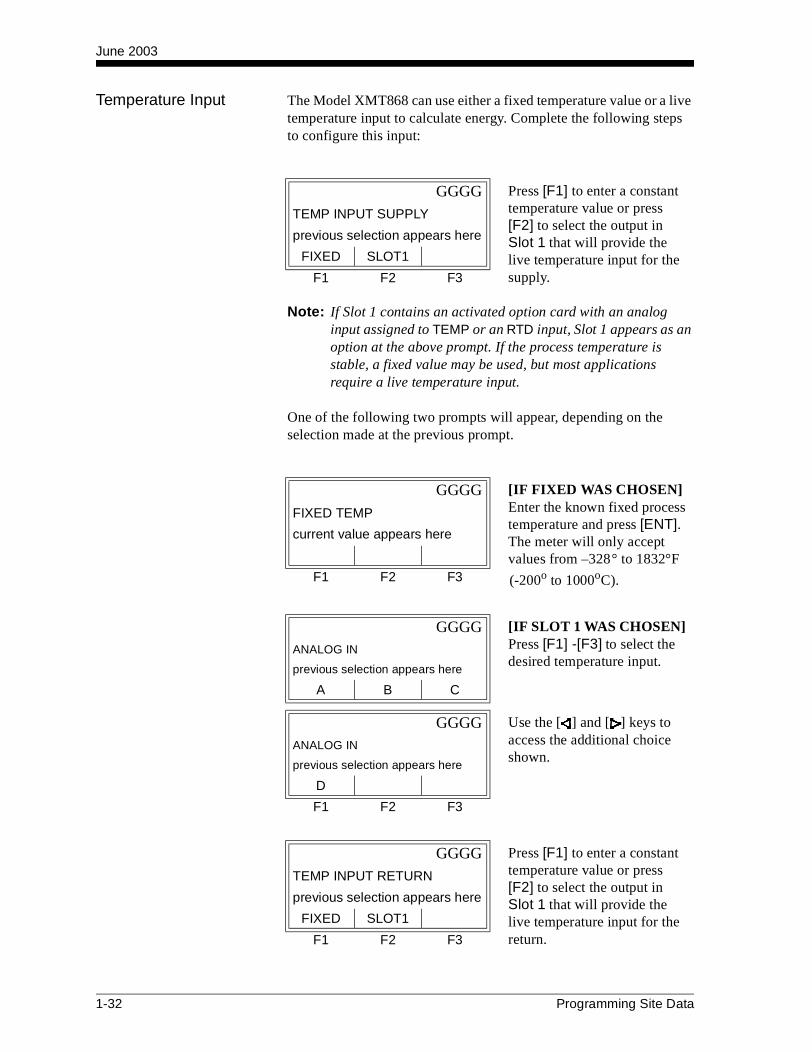
Temperature Input The Model XMT868 can use either a fixed temperature value or a live temperature input to calculate energy. Complete the following steps to configure this input:
Note: If Slot 1 contains an activated option card with an analog input assigned to TEMP or an RTD input, Slot 1 appears as an option at the above prompt. If the process temperature is stable, a fixed value may be used, but most applications require a live temperature input.
One of the following two prompts will appear, depending on the selection made at the previous prompt.
GGGG Press [F1] to enter a constant temperature value or press [F2] to select the output in Slot 1 that will provide the live temperature input for the supply.
TEMP INPUT SUPPLY
previous selection appears here
FIXED SLOT1
F1 F2 F3
GGGG [IF FIXED WAS CHOSEN] Enter the known fixed process temperature and press [ENT]. The meter will only accept values from –328° to 1832°F
(-200o to 1000oC).
FIXED TEMP
current value appears here
F1 F2 F3
GGGG [IF SLOT 1 WAS CHOSEN] Press [F1] -[F3] to select the desired temperature input.
ANALOG IN
previous selection appears here
A B C
GGGG Use the [ ] and [ ] keys to access the additional choice shown.
ANALOG IN
previous selection appears here
D
F1 F2 F3
GGGG Press [F1] to enter a constant temperature value or press [F2] to select the output in Slot 1 that will provide the live temperature input for the return.
TEMP INPUT RETURN
previous selection appears here
FIXED SLOT1
F1 F2 F3
1-32 Programming Site Data

June 2003
Temperature Input (cont.)
Note: If Slot 1 contains an activated option card with an analog input assigned to TEMP or an RTD input, Slot 1 appears as an option at the above prompt. If the process temperature is stable, a fixed value may be used, but most applications require a live temperature input.
One of the following two prompts will appear, depending on the selection made at the previous prompt.
The display now takes you back to the top menu, ACTIV, SYSTM, PIPE, I/O, SETUP. At this point, you can proceed programming in this sub-menu as desired. To leave the Channel PROGRAM sub-menu, press the [EXIT] key on the RCCU keypad. To complete setting up the meter, you must enter data in the GLOBL-SYSTM sub-menu as described on page 1-52.
GGGG [IF FIXED WAS CHOSEN] Enter the known fixed process temperature and press [ENT]. The meter will only accept values from –328° to 1832°F
(-200o to 1000oC).
FIXED TEMP
current value appears here
F1 F2 F3
GGGG [IF SLOT 1 WAS CHOSEN] Press [F1] -[F3] to select the desired temperature input.
ANALOG IN
previous selection appears here
A B C
GGGG Use the [ ] and [ ] keys to access the additional choice shown.
ANALOG IN
previous selection appears here
D
F1 F2 F3
Programming Site Data 1-33

June 2003
The Setup Sub-Menu The signal limits and response times for the Model XMT868 are specified via the SETUP sub-menu. While following the programming instructions, refer to Figure A-3 on page A-3 of Appendix A, Menu Maps. The following three sub-menus are included in this section:
• SIGNL - set the parameters related to the transducer signal
• AVRG - specify the response of the meter to step changes
• INIT - initialize all parameters to default values
• ADVAN - enable mass flow, edit kinematic viscosity vs. sound speed table, activate K factors, and select transmit code length.
Enter the SETUP sub-menu by pressing [ ] + [F2] at the Channel PROGRAM prompt on page 1-11 and complete the following steps:
Proceed to the appropriate sub-section to program the option selection made at the above prompt. Remember to record all programmed data in Appendix B, Data Records.
GGGG Press [F1]-[F3] to select the desired SETUP option.SET UP
previous selection appears here
SIGNL AVRG INIT
GGGG Use the [ ] and [ ] keys to access the additional choice shown.
SET UP
previous selection appears here
ADVAN
F1 F2 F3
1-34 Programming Site Data
June 2003
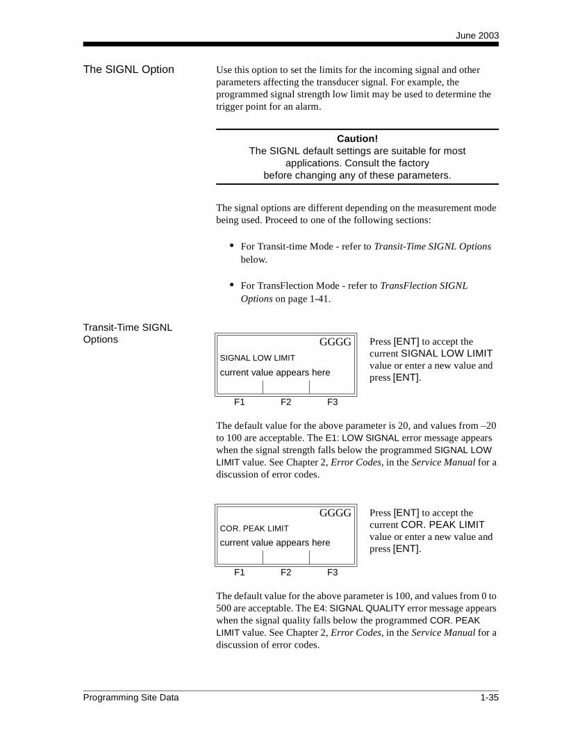
The SIGNL Option Use this option to set the limits for the incoming signal and other parameters affecting the transducer signal. For example, the programmed signal strength low limit may be used to determine the trigger point for an alarm.
Caution!The SIGNL default settings are suitable for most
applications. Consult the factorybefore changing any of these parameters.
The signal options are different depending on the measurement mode being used. Proceed to one of the following sections:
• For Transit-time Mode - refer to Transit-Time SIGNL Options below.
• For TransFlection Mode - refer to TransFlection SIGNL Options on page 1-41.
Transit-Time SIGNL Options
The default value for the above parameter is 20, and values from –20 to 100 are acceptable. The E1: LOW SIGNAL error message appears when the signal strength falls below the programmed SIGNAL LOW LIMIT value. See Chapter 2, Error Codes, in the Service Manual for a discussion of error codes.
The default value for the above parameter is 100, and values from 0 to 500 are acceptable. The E4: SIGNAL QUALITY error message appears when the signal quality falls below the programmed COR. PEAK LIMIT value. See Chapter 2, Error Codes, in the Service Manual for a discussion of error codes.
GGGG Press [ENT] to accept the current SIGNAL LOW LIMIT value or enter a new value and press [ENT].
SIGNAL LOW LIMIT
current value appears here
F1 F2 F3
GGGG Press [ENT] to accept the current COR. PEAK LIMIT value or enter a new value and press [ENT].
COR. PEAK LIMIT
current value appears here
F1 F2 F3
Programming Site Data 1-35

June 2003
Transit-Time SIGNL Options (cont.)
The default value for the above parameter is 20%, and values from 1% to 50% are acceptable. The E2: SOUNDSPEED error message appears when the calculated fluid soundspeed differs from the fluid soundspeed entered in the CHx-SYSTM menu by more than the programmed SOUNDSPEED +– LIMIT value. See Chapter 2, Error Codes, in the Service Manual for a discussion of error codes.
The default value for the above parameter is –150.0 ft/sec. (–46 m/sec.) and values from –500 to 500 ft/sec. (–150 to 150 m/sec.) are acceptable. The E3: VELOCITY RANGE error message appears when the calculated fluid velocity is less than the programmed VELOCITY LOW LIMIT value. See Chapter 2, Error Codes, in the Service Manual for a discussion of error codes.
The default value for the above parameter is 150.0 ft/sec (46 m/sec) and –500 to 500 ft/sec (–150 to 150 m/sec) are acceptable values. The E3: VELOCITY RANGE error message appears when the calculated fluid velocity exceeds the programmed VELOCITY HIGH LIMIT value. See Chapter 2, Error Codes, in the Service Manual for a discussion of error codes.
GGGG Press [ENT] to accept the current SOUNDSPEED +– LIMIT value or enter a new value and press [ENT].
SOUNDSPEED +– LIMI
current value appears here
F1 F2 F3
GGGG Press [ENT] to accept the current VELOCITY LOW LIMIT value or enter a new value and press [ENT].
VELOCITY LOW LIMIT
current value appears here
F1 F2 F3
GGGG Press [ENT] to accept the current VELOCITY HIGH LIMIT value or enter a new value and press [ENT].
VELOCITY HIGH LIMI
current value appears here
F1 F2 F3
1-36 Programming Site Data

June 2003
Transit-Time SIGNL Options (cont.)
The default value for the above parameter is 15.0 ft/sec2 (4.6 m/sec2)
and values from 0 to 100 ft/sec2 (0 to 30 m/sec2) are acceptable. The E6: CYCLE SKIP error message appears when the calculated fluid velocity changes by more than the programmed ACCELERATION LIMIT value from one reading to the next. See Chapter 2, Error Codes, in the Service Manual for a discussion of error codes.
The amplitude discriminator measures the transducer signal received by the Model XMT868. The default value for the above parameter is 14, and values from 0 to 100 are acceptable. The E5: AMPLITUDE error message appears when the amplitude discriminator falls below the programmed AMP. DISCRIM LOW value. See Chapter 2, Error Codes, in the Service Manual for a discussion of error codes.
The amplitude discriminator measures the transducer signal received by the Model XMT868. The default value for the above parameter is 34, and values from 0 to 100 are acceptable. The E5: AMPLITUDE error message appears when the amplitude discriminator exceeds the programmed AMP. DISCRIM HIGH value. See Chapter 2, Error Codes, in the Service Manual for a discussion of error codes.
GGGG Press [ENT] to accept the current ACCELERATION value or enter a new value and press [ENT].
ACCELERATION LIMIT
current value appears here
F1 F2 F3
GGGG Press [ENT] to accept the current AMP. DISCRIM LOW value or enter a new value and press [ENT].
AMP. DISCRIM LOW
current value appears here
F1 F2 F3
GGGG Press [ENT] to accept the current AMP. DISCRIM HIGH value or enter a new value and press [ENT].
AMP. DISCRIM HIGH
current value appears here
F1 F2 F3
Programming Site Data 1-37

June 2003
Transit-Time SIGNL Options (cont.)
An offset between the upstream and downstream transit times is specified at this prompt. The default value for the above parameter is 0 µsec, and values from –1000 to 1000 µsec are acceptable.
The percentage of peak used to calculate the transit times and Delta T is specified at this prompt. The default value for the above parameter is 50%, and values from -100 to 100% are acceptable.
Note: This setting is a starting point for detecting the signal. The meter will automatically adjust this value if the calculated transit time is unacceptable. You can set the limits for this value using the MIN. PEAK% and MAX. PEAK% discussed on page 1-40.
The transmitter voltage can be set to low or high to reduce power consumption. LOW (default setting) is typically selected for smaller pipes with a single-phase fluid. The LOW setting is normally sufficient. HIGH is usually selected for large pipes or pipes with one or more phases.
GGGG Press [ENT] to accept the current DELTA T OFFSET value or enter a new value and press [ENT].
DELTA T OFFSET
current value appears here
F1 F2 F3
GGGG Press [ENT] to accept the current % of Peak value or enter a new value and press [ENT].
% of Peak
current value appears here
F1 F2 F3
GGGG Press [F1] to select LOW (default) or [F2] to select HIGH.
TRANSMITTER VOLTAGE
current value appears here
LOW HIGH
F1 F2 F3
1-38 Programming Site Data

June 2003
Transit-Time SIGNL Options (cont.)
Both the upstream and downstream transducers transmit ultrasonic pulses in bursts, which consist of a series of transmit pulses. XMIT SAMPLE SIZE determines how many bursts are sent in one direction before sending in the other direction. The default value for the above parameter is 8 and values of 2, 4, 8, 16 and 32 are acceptable.
Use this prompt to enter the number of errors the XMT868 can record before it displays an error message. The default value is 8.
Use this prompt to enter the minimum percent of peak that the XMT868 can use to measure transit time. The XMT868 accepts values from -100 to 100.
GGG| Use the [ ] and [ ] keys to access the options shown, and press the [Fx] key under the desired value to select it.
XMIT SAMPLE SIZE
current value appears here
2 4 8
GGG|
XMIT SAMPLE SIZE
current value appears here
16 32
F1 F2 F3
GGGG Press [ENT] to accept the current # OF ERRORS value or enter a new value (0 to 16) and press [ENT].
# OF ERRORS
current value appears here
F1 F2 F3
GGGG Press [ENT] to accept the current minimum percent of peak value or enter a new value and press [ENT].
Minimum Peak% limi
current value appears here
F1 F2 F3
Programming Site Data 1-39

June 2003
Transit-Time SIGNL Options (cont.)
Use this prompt to enter the maximum percent of peak that the XMT868 can use to measure transit time. The XMT868 accepts values from -100 to 100.
After responding to the above prompt, the meter returns to the SETUP prompt shown on page 1-34. To leave the User Program, press the [EXIT] key twice.
GGGG Press [ENT] to accept the current maximum percent of peak value or enter a new value and press [ENT].
Maximum Peak% limi
current value appears here
F1 F2 F3
1-40 Programming Site Data

June 2003
TransFlection SIGNL Options
The default value for the above parameter is 20, and values from –20 to 100 are acceptable. The E1: LOW SIGNAL error message appears when the signal strength falls below the programmed SIGNAL LOW LIMIT value. See Chapter 2, Error Codes, in the Service Manual for a discussion of error codes.
The default value for the above parameter is –150.0 ft/sec (–46 m/sec) and values from –500 to 500 ft/sec (–150 to 150 m/sec) are acceptable. The E3: VELOCITY RANGE error message appears when the calculated fluid velocity is less than the programmed VELOCITY LOW LIMIT value. See Chapter 2, Error Codes, in the Service Manual for a discussion of error codes.
The default value for the above parameter is 150.0 ft/sec (46 m/sec) and –500 to 500 ft/sec (–150 to 150 m/sec) are acceptable values. The E3: VELOCITY RANGE error message appears when the calculated fluid velocity exceeds the programmed VELOCITY HIGH LIMIT value. See Chapter 2, Error Codes, in the Service Manual for a discussion of error codes.
GGGG Press [ENT] to accept the current SIGNAL LOW LIMIT value or enter a new value and press [ENT].
SIGNAL LOW LIMIT
current value appears here
F1 F2 F3
GGGG Press [ENT] to accept the current VELOCITY LOW LIMIT value or enter a new value and press [ENT].
VELOCITY LOW LIMIT
current value appears here
F1 F2 F3
GGGG Press [ENT] to accept the current VELOCITY HIGH LIMIT value or enter a new value and press [ENT].
VELOCITY HIGH LIMIT
current value appears here
F1 F2 F3
Programming Site Data 1-41

June 2003
TransFlection SIGNL Options (cont.)
The transmitter voltage can be set to low or high to conserve battery life. LOW (default setting) is typically selected for smaller pipes with a single-phase fluid. The LOW setting prolongs the life of the battery. HIGH is usually selected for large pipes or pipes with one or more phases.
FLOW DIRECTION specifies the direction the fluid is flowing. The XMT868 normally measures the absolute value of flow velocity; however, this prompts lets you to select which direction the transducers face.
Note: If you select UP or DOWN, the TransFlection measurement range is cut in half from 1 to 30 ft/s (0.3 to 9 m/s) to -15 to 15 ft/s (-4.6 to 4.6 m/s).
GGGG Press [F1] to select LOW (default) or [F2] to select HIGH.
TRANSMITTER VOLTAGE
current value appears here
LOW HIGH
F1 F2 F3
GGGG Press [F1], to select absolute flow velocity, press [F2], if the transducers face against the flow, or press [F3], if the trans-ducers face with the flow.
FLOW DIRECTION
current value appears here
OFF UP DOWN
F1 F2 F3
1-42 Programming Site Data

June 2003
TransFlection SIGNL Options (cont.)
The repetition period sets the time interval between transmissions. Increasing the repetition period reduces the amount of background noise in the signal at the expense of reducing the maximum measurable flow rate. Since XMT868 adjusts this parameter to optimize the flow measurement (taking flow rate, transducer frequency, and signal characteristics into consideration), you must enter a range. REP PERIOD 1 specifies the shortest period. REP PERIOD 2 specifies the longest period. The default for REP PERIOD 1 is 200 µsecs and 800 µsecs for REP PERIOD 2.
Note: Once the XMT868 determines the appropriate repetition period within the defined limits, it alternates between transmits at the determined repetition period and a period that is 20% longer. For example, if the XMT868 selects a repetition period of 200 µsecs, it will first transmit a series of bursts at 200 µsecs, followed by a series at 240 µsecs. The XMT868 then compares the receive signals of the first series of burst to the receive signals of the second series. If the two receive signals are too dissimilar, the XMT868 displays an incoherent signal error.
XMITS PER READING specifies the number of transmissions used by the XMT868 to obtain a flow rate measurement. Reducing this number improves the flowmeter’s response time, but reduces the flowmeter’s sensitivity in poor signal conditions. The default value is 5,000.
GGGG Press [F1]-[F3] to select the appropriate REP PERIOD and press [ENT].
REP PERIOD 1 (OR 2)
current value appears here
100 200 400
GGGG Use the [ ] and [ ] keys to access the additional choice shown.
REP PERIOD 1 (OR 2)
current value appears here
800 1600 3200
F1 F2 F3
GGGG Press [ENT] to accept the current XMITS PER READING value or enter a new value (1,024 to 30,000) and press [ENT].
XMITS PER READING
current value appears here
F1 F2 F3
Programming Site Data 1-43

June 2003
TransFlection SIGNL Options (cont.)
Note: To calculate the response time, divide the XMITS PER READING value by the number of transmissions per second. The number of transmissions per second is calculated by dividing 1 second by the repetition period. For example, if the XMITS PER READING value is 10,000 and the repetition period is 200 µsecs, the number of transmissions per second is 5,000 (1 sec divided by 200 µsec), and the response time is 2 seconds (10,000 xmits/rdg divided by 5,000 xmits/sec). Refer to Table 1-11 for more examples.
The WEAK SIGNAL THRESHOLD option lets you enter a value for the two-phase threshold. When the two-phase signal falls below the WEAK SIGNAL THRESHOLD value, the E10: WEAK SIGNAL error message appears on the display. The default value is 20.
The CODE LENGTH lets you enter a value for the number of pulses per transmission. The default values 8 pulses.
Table 1-11: Examples of Response Time vs. Xmits per Reading and Repetition Rate
Xmits per Reading
Repetition Rates
200 µsecs =5,000 xmits/sec
800 µsecs = 1,250 xmits/sec
30,000 6 seconds 24 seconds
5,000 1 second 4 seconds
GGGG Press [ENT] to accept the current WEAK SIGNAL THRESHOLD value or enter a new value (0 to 100) and press [ENT].
WEAK SIGNAL THRESH
current value appears here
F1 F2 F3
GGGG Press [F1]-[F3] to select the appropriate CODE LENGTH and press [ENT].
CODE LENGTH
current value appears here
1 4 8
GGGG Use the [ ] and [ ] keys to access the additional choice shown.
CODE LENGTH
current value appears here
16
F1 F2 F3
1-44 Programming Site Data

June 2003
TransFlection SIGNL Options (cont.)
The FILTER WIDTH lets you enter a number of samples of the digitized receive signal that the XMT868 uses to estimate the arrival of the transducer signal. The default value is 50 (5 cycles).
The AVERAGING FACTOR lets you enter a value for an algorithm that the XMT868 uses to eliminate background noise. The default value is 5.
Use this prompt to enter the number of errors the XMT868 can record before it displays an error message. The default value is 8.
After responding to the above prompt, the meter returns to the SETUP prompt shown onpage 1-34. To leave the User Program, press the [EXIT] key twice.
GGGG Press [ENT] to accept the current FILTER WIDTH value or enter a new value (8 to 64) and press [ENT].
FILTER WIDTH
current value appears here
F1 F2 F3
GGGG Press [ENT] to accept the current AVERAGING FACTOR value (0 to 16) or enter a new value and press [ENT].
AVERAGING FACTOR
current value appears here
F1 F2 F3
GGGG Press [ENT] to accept the current # OF ERRORS value or enter a new value (1 to 16) and press [ENT].
# OF ERRORS ALLOWE
current value appears here
F1 F2 F3
Programming Site Data 1-45
June 2003
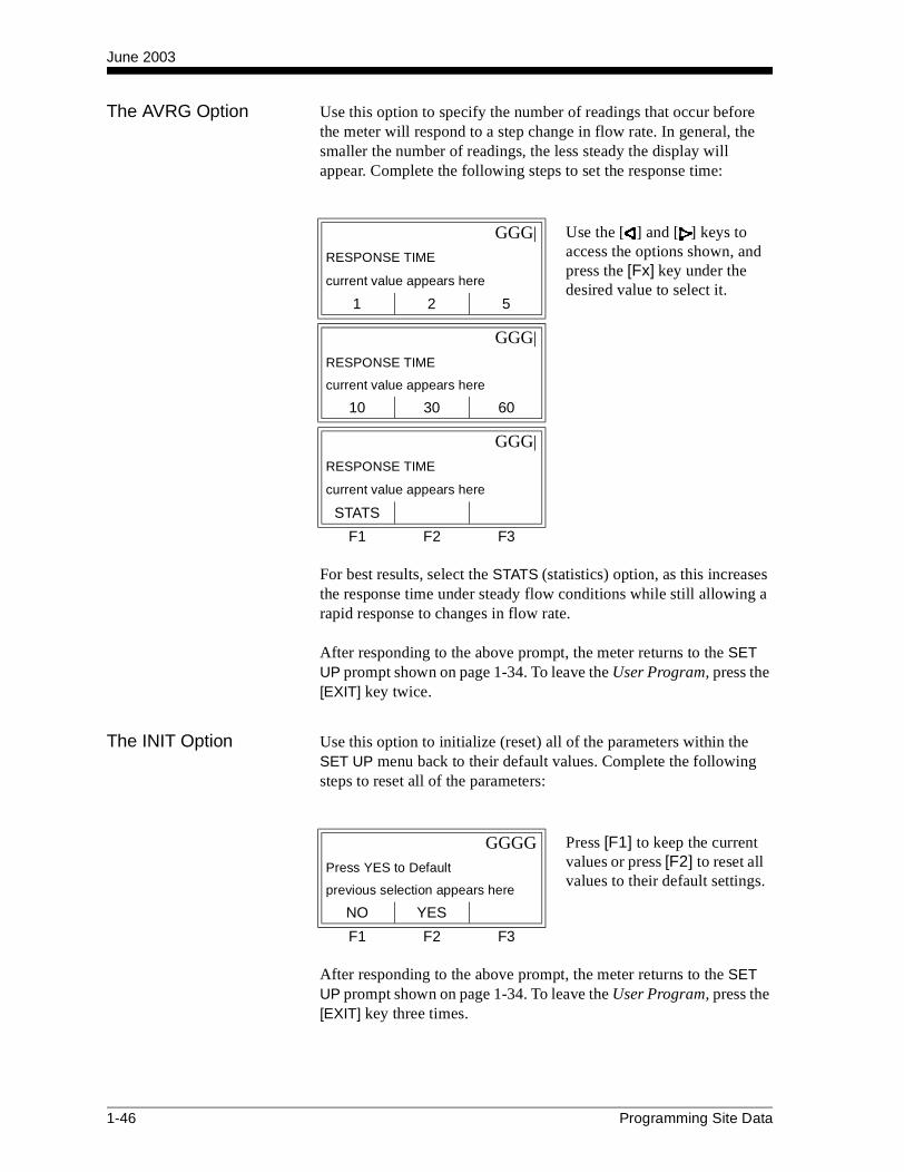
The AVRG Option Use this option to specify the number of readings that occur before the meter will respond to a step change in flow rate. In general, the smaller the number of readings, the less steady the display will appear. Complete the following steps to set the response time:
For best results, select the STATS (statistics) option, as this increases the response time under steady flow conditions while still allowing a rapid response to changes in flow rate.
After responding to the above prompt, the meter returns to the SET UP prompt shown on page 1-34. To leave the User Program, press the [EXIT] key twice.
The INIT Option Use this option to initialize (reset) all of the parameters within the SET UP menu back to their default values. Complete the following steps to reset all of the parameters:
After responding to the above prompt, the meter returns to the SET UP prompt shown on page 1-34. To leave the User Program, press the [EXIT] key three times.
GGG| Use the [ ] and [ ] keys to access the options shown, and press the [Fx] key under the desired value to select it.
RESPONSE TIME
current value appears here
1 2 5
GGG|
RESPONSE TIME
current value appears here
10 30 60
GGG|
RESPONSE TIME
current value appears here
STATS
F1 F2 F3
GGGG Press [F1] to keep the current values or press [F2] to reset all values to their default settings.
Press YES to Default
previous selection appears here
NO YES
F1 F2 F3
1-46 Programming Site Data

June 2003
The ADVAN Option This option enables you to enable the more advanced features of the meter. In this option you can do the following:
• calculate the kinematic viscosity (KV) based on signal strength (SS)
• enter a table of K-factors (based on velocity or reynolds number) that compensates for non-linear flow rates
• enable mass flow (calculated for static fluid density)
• select the size of the transducer transmission signal.
The KV/SS Option Use this option to calculate the kinematic viscosity (KV) based on signal strength (SS). To use this option, you must enter the KV vs. SS pairs in descending order of KV and ascending order of SS. For example, if pair 1 is KV = 10 centistrokes and SS = 62, then pair 2 must be KV ≤ 10 centistrokes and SS ≥ 62. The XMT868 accepts 2 to 20 pairs. Complete the following steps to enter KV and SS values:
GGG| Use the [ ] and [ ] keys to access the options shown. Press the [Fx] key under the desired value to select it and proceed to one of the following sections.
Advanced Features
previous selection appears here
KV/SS MULTK MASS
GGG|
Advanced Features
previous selection appears here
CODEL
F1 F2 F3
GGGG Press [ENT] to accept the current value or enter a new value (2 to 20) and press [ENT].
# of KV/SS pairs?
current value appears here
F1 F2 F3
Programming Site Data 1-47

June 2003
The KV/SS Option (cont.)
The SIG STRENGTH and KIN VISCOSITY prompts repeat for each pair. After entering all the pairs, the meter returns to the ADVANCED FEATURES prompt shown on page 1-47. To leave the User Program, press the [EXIT] key four times.
The MULTK Option Use this option to enter a table of K-factors. K-factors are used to create a curve for the flow range (based on velocity or reynolds number) that compensates for non-linear flow rates. The meter accepts from 2 to 20 pairs. Complete the following steps to enter multiple K factors for velocity or reynolds values:
If NO was selected, the meter returns to the ADVANCED FEATURES prompt shown on page 1-47. To leave the User Program, press the [EXIT] key four times. If YES was selected. proceed to the next prompt.
GGGG Press [ENT] to accept the current SIG STRENGTH value or enter a new value (50.0 to 85.0) and press [ENT]. Enter the signal strength values in ascending order.
SIG STRENGTH #XX
current value appears here
F1 F2 F3
GGGG Press [ENT] to accept the current KINEMATIC VISCOSITY value or enter a new value (0.050 to 500) and press [ENT]. Enter the kinematic viscosity values in descending order.
KIN VISCOSITY #XX
current value appears here
cSTKS
F1 F2 F3
GGGG Press [F1] to disable this option or [F2] to enable multiple K factors.
Activate Multi K Fa
previous selection appears here
NO YES
F1 F2 F3
GGGG Press [F1] to customize velocity values or [F2] to customize reynolds values.
Custom type
previous selection appears here
CstV CstR
F1 F2 F3
1-48 Programming Site Data

June 2003
The MULTK Option (cont.)
Note: If the necessary velocity/reynolds vs. K-factor data was not provided with the Model XMT868’s documentation, the K-factor table cannot be edited.
If NO was selected, the meter returns to the ADVANCED FEATURES prompt shown on page 1-47. To leave the User Program, press the [EXIT] key four times. If YES was selected. proceed to the next prompt.
Note: When editing the K-factor table, the velocities must be entered in increasing order.
The VELOCITY # and K FACTOR # prompts repeat for each pair. After entering all the pairs, the meter returns to the ADVANCED FEATURES prompt shown on page 1-47. To leave the User Program, press the [EXIT] key four times.
GGGG Press [F1] to retain the current K-factor table or [F2] to edit the K-factor table.
Edit table?
previous selection appears here
NO YES
F1 F2 F3
GGGG Enter the number of K-factors to be entered into the table and press [ENT]. This number must be between 2 and 20.
Enter # of K factors
previous selection appears here
F1 F2 F3
GGGG Enter the velocity/reynolds value for K-factor number “X” and press [ENT].
Vel/Reyn # X
previous selection appears here
F1 F2 F3
GGGG Enter the K-factor corresponding to velocity/reynolds number “X” (0.333 to 3.0) and press [ENT].
K Factor # X
previous selection appears here
F1 F2 F3
Programming Site Data 1-49
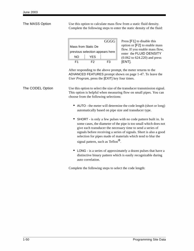
June 2003
The MASS Option Use this option to calculate mass flow from a static fluid density. Complete the following steps to enter the static density of the fluid:
After responding to the above prompt, the meter returns to the ADVANCED FEATURES prompt shown on page 1-47. To leave the User Program, press the [EXIT] key four times.
The CODEL Option Use this option to select the size of the transducer transmission signal. This option is helpful when measuring flow on small pipes. You can choose from the following selections:
• AUTO - the meter will determine the code length (short or long) automatically based on pipe size and transducer type.
• SHORT - is only a few pulses with no code pattern built in. In some cases, the diameter of the pipe is too small which does not give each transducer the necessary time to send a series of signals before receiving a series of signals. Short is also a good selection for pipes made of materials which tend to blur the
signal pattern, such as Teflon.
• LONG - is a series of approximately a dozen pulses that have a distinctive binary pattern which is easily recognizable during auto correlation.
Complete the following steps to select the code length:
GGGG Press [F1] to disable this option or [F2] to enable mass flow. If you enable mass flow, enter the FLUID DENSITY (0.062 to 624.220) and press [ENT].
Mass from Static De
previous selection appears here
NO YES
F1 F2 F3
1-50 Programming Site Data
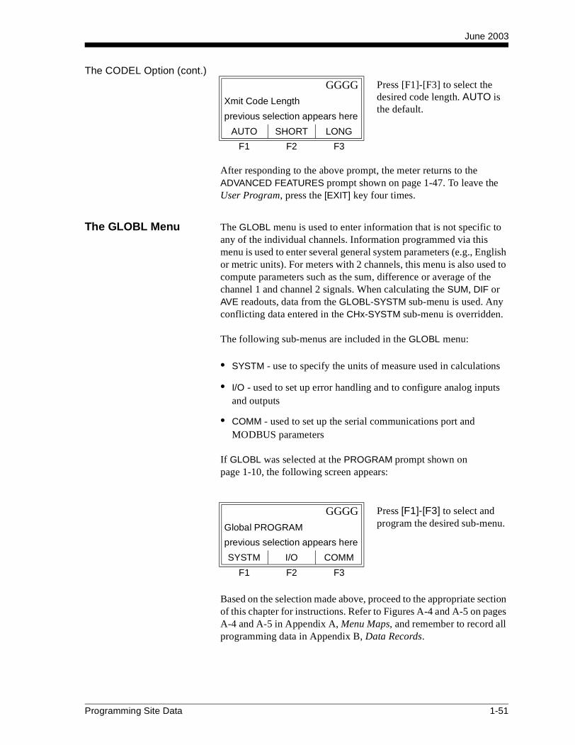
June 2003
The CODEL Option (cont.)
After responding to the above prompt, the meter returns to the ADVANCED FEATURES prompt shown on page 1-47. To leave the User Program, press the [EXIT] key four times.
The GLOBL Menu The GLOBL menu is used to enter information that is not specific to any of the individual channels. Information programmed via this menu is used to enter several general system parameters (e.g., English or metric units). For meters with 2 channels, this menu is also used to compute parameters such as the sum, difference or average of the channel 1 and channel 2 signals. When calculating the SUM, DIF or AVE readouts, data from the GLOBL-SYSTM sub-menu is used. Any conflicting data entered in the CHx-SYSTM sub-menu is overridden.
The following sub-menus are included in the GLOBL menu:
• SYSTM - use to specify the units of measure used in calculations
• I/O - used to set up error handling and to configure analog inputs and outputs
• COMM - used to set up the serial communications port and MODBUS parameters
If GLOBL was selected at the PROGRAM prompt shown onpage 1-10, the following screen appears:
Based on the selection made above, proceed to the appropriate section of this chapter for instructions. Refer to Figures A-4 and A-5 on pages A-4 and A-5 in Appendix A, Menu Maps, and remember to record all programming data in Appendix B, Data Records.
GGGG Press [F1]-[F3] to select the desired code length. AUTO is the default.
Xmit Code Length
previous selection appears here
AUTO SHORT LONG
F1 F2 F3
GGGG Press [F1]-[F3] to select and program the desired sub-menu.Global PROGRAM
previous selection appears here
SYSTM I/O COMM
F1 F2 F3
Programming Site Data 1-51

June 2003
The GLOBL-SYSTM Sub-Menu
While completing these instructions, refer to the menu map in Figure A-4 on page A-4 in Appendix A, Menu Maps. To enter this sub-menu, press [F1] at the Global PROGRAM prompt shown on the previous page.
For single-channel units, the meter exits the SYSTM sub-menu and returns to the Global PROGRAM prompt shown on the previous page. To leave the User Program, press the [EXIT] key twice.
For 2-channel units, proceed to the following prompt.
The abbreviations and definitions of all the available volumetric and totalizer units are shown in Table 1-12 on page 1-53.
Key in the desired METER MESSAGE (up to 21 characters) and press [ENT].
METER MESSAGE
current message appears here
F1 F2 F3
GGGG Press [F1] to display parameters and measurements in English units or press [F2] to display parameters and measurements in metric units.
SYSTEM UNITS
previous selection appears here
ENG METRC
F1 F2 F3
GGG| Press [F1]-[F3] to select the desired volumetric units for the flow rate display.
VOLUMETRIC UNITS
current selection appears here
GAL/S GAL/M GAL/H
GGG| Use the [ ] and [ ] keys to access the additional choices shown.
VOLUMETRIC UNITS
current selection appears here
MGD ft3/s ft3/m
F1 F2 F3
1-52 Programming Site Data
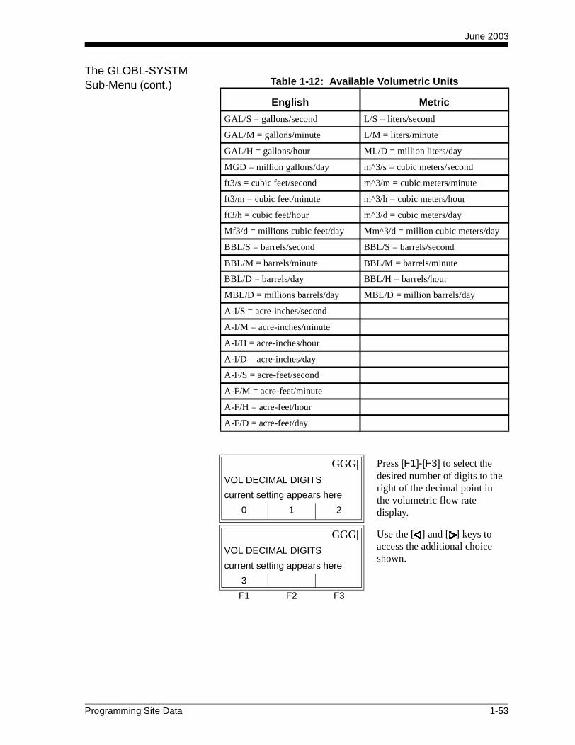
June 2003
The GLOBL-SYSTM Sub-Menu (cont.) Table 1-12: Available Volumetric Units
English Metric
GAL/S = gallons/second L/S = liters/second
GAL/M = gallons/minute L/M = liters/minute
GAL/H = gallons/hour ML/D = million liters/day
MGD = million gallons/day m^3/s = cubic meters/second
ft3/s = cubic feet/second m^3/m = cubic meters/minute
ft3/m = cubic feet/minute m^3/h = cubic meters/hour
ft3/h = cubic feet/hour m^3/d = cubic meters/day
Mf3/d = millions cubic feet/day Mm^3/d = million cubic meters/day
BBL/S = barrels/second BBL/S = barrels/second
BBL/M = barrels/minute BBL/M = barrels/minute
BBL/D = barrels/day BBL/H = barrels/hour
MBL/D = millions barrels/day MBL/D = million barrels/day
A-I/S = acre-inches/second
A-I/M = acre-inches/minute
A-I/H = acre-inches/hour
A-I/D = acre-inches/day
A-F/S = acre-feet/second
A-F/M = acre-feet/minute
A-F/H = acre-feet/hour
A-F/D = acre-feet/day
GGG| Press [F1]-[F3] to select the desired number of digits to the right of the decimal point in the volumetric flow rate display.
VOL DECIMAL DIGITS
current setting appears here
0 1 2
GGG| Use the [ ] and [ ] keys to access the additional choice shown.
VOL DECIMAL DIGITS
current setting appears here
3
F1 F2 F3
Programming Site Data 1-53
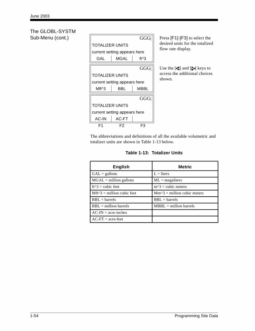
June 2003
The GLOBL-SYSTM Sub-Menu (cont.)
The abbreviations and definitions of all the available volumetric and totalizer units are shown in Table 1-13 below.
Table 1-13: Totalizer Units
GGG| Press [F1]-[F3] to select the desired units for the totalized flow rate display.
TOTALIZER UNITS
current setting appears here
GAL MGAL ft^3
GGG| Use the [ ] and [ ] keys to access the additional choices shown.
TOTALIZER UNITS
current setting appears here
Mft^3 BBL MBBL
GGG|
TOTALIZER UNITS
current setting appears here
AC-IN AC-FT
F1 F2 F3
English MetricGAL = gallons L = liters
MGAL = million gallons ML = megaliters
ft^3 = cubic feet m^3 = cubic meters
Mft^3 = million cubic feet Mm^3 = million cubic meters
BBL = barrels BBL = barrels
BBL = million barrels MBBL = million barrels
AC-IN = acre-inches
AC-FT = acre-feet
1-54 Programming Site Data

June 2003
The GLOBL-SYSTM Sub-Menu (cont.)
The I/O Sub-Menu Set up the XMT868’s inputs and outputs via the I/O sub-menu. While following the programming instructions, refer to Figures A-4 and A-5 on pages A-4 and A-5 in Appendix A, Menu Maps. The I/O sub-menu consists of the following:
• ERROR - program the meter’s response during an error condition
• OPTN - set up any option cards and the Slot 0 analog outputs
• LCD - set up the optional LCD display (refer to Chapter 2, Displaying Data)
To enter the I/O sub-menu, press [F2] at the Global PROGRAM prompt shown on the previous page.
Note: In this section, Slot 1 appears as an option only if a suitable option card is installed in Slot 1.
Proceed to the appropriate section to program the option selection made at the above prompt. Remember to record all programmed data in Appendix B, Data Records.
GGG| Press [F1]-[F3] to select the desired number of digits to the right of the decimal point in the totalized flow rate display.
TOTAL DECIMAL DIGITS
current setting appears here
0 1 2
GGG| Use the [ ] and [ ] keys to access the additional choice shown.
TOTAL DECIMAL DIGITS
current setting appears here
3
F1 F2 F3
GGGG Press the [Fx] key under the desired option to select it.Global I/O
previous selection appears here
ERROR OPTN LCD
F1 F2 F3
Programming Site Data 1-55

June 2003
The ERROR Option This menu option lets you set how the XMT868 will handle the outputs for measurements and average (two-path) measurements during an error condition. See Chapter 2, Error Codes, in the Service Manual for a discussion of the built-in error codes.
To access this sub-menu, press [F1] at the Global I/O prompt shown on the previous page.
Error Handling for Measurements - VEL, VOL..., SUM, DIF
See Table 1-14 below and Table 1-15 on the following page for a description of the error handling options available and how the totalizers and display responds to them for a single and two-channel meter.
GGG| Use the [ ] and [ ] keys to access the options shown. Press the [Fx] key under the desired error response option.
ERROR HANDLING
previous selection appears here
HOLD LOW HIGH
GGG|
ERROR HANDLING
previous selection appears here
HHIGH
F1 F2 F3
Table 1-14: Error Options and Responsesfor a Single-Channel Meter
Option Output Response Totalizer Response
HOLD Holds the last “good” reading Holds the last “good” reading and continues to totalize, based on that reading
LOW Forces the outputs to the low set point
Stops totalizing
HIGH Forces the outputs to the high set point
Stops totalizing
HHIGH Forces the outputs ≈10% above the high set point
Stops totalizing
1-56 Programming Site Data

June 2003
Error Handling for Measurements - VEL, VOL..., SUM, DIF (cont.)
For a one-channel meter, after responding to the above prompt, the meter returns to the Global I/O prompt shown on the previous page. To leave the User Program, press the [EXIT] key twice. For a two-channel meter, complete the rest of this section.
Error Handling for Average Measurements - AVE
The 2PATH ERROR HANDLING option is intended for applications where two sets of transducers are installed in the same location in the same pipe to improve accuracy and the meter is operated in AVE mode. With this function enabled, the Model XMT868 performs error handling only if both channels are in error. If this function is disabled, error handling occurs when either channel goes into error.
Specific responses of the display and the totalizer to the two-path error handling option available at the above prompt are listed in Table 1-16 on the following page.
Table 1-15: Error Options and Responsesfor a 2-Channel Meter
When MeasuringDisplay
Response
Totalizer Response When Error Handling is
HOLDLOW, HIGH,
HHIGH
CH1 or CH2(vel, vol, etc.)
Holds last “good” reading.
Holds last “good” reading and continues to totalize based on that “good” reading.
Stops totalizing.
SUM Adds two channels using the last “good” reading.
Holds last “good” reading and continues to totalize based on two channels.
Stops totalizing if either or both channels go into error.
DIF Subtracts two channels using the last “good” reading.
Holds last “good” reading and continues to totalize based on two channels.
Stops totalizing if either or both channels go into error.
AVE See Error Handling for Average Measurements below.
GGGG Press [F1] to disable two-path error handling, or press [F2] to enable two-path error handling.
2PATH ERROR HANDLI
previous selection appears here
NO YES
F1 F2 F3
Programming Site Data 1-57
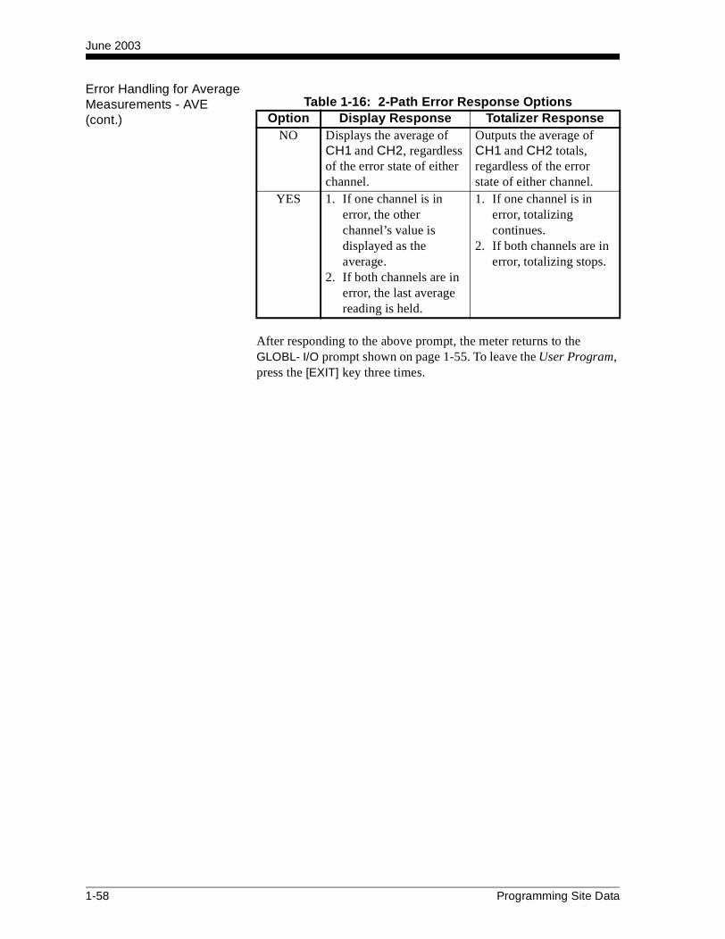
June 2003
Error Handling for Average Measurements - AVE (cont.)
After responding to the above prompt, the meter returns to the GLOBL- I/O prompt shown on page 1-55. To leave the User Program, press the [EXIT] key three times.
Table 1-16: 2-Path Error Response OptionsOption Display Response Totalizer Response
NO Displays the average of CH1 and CH2, regardless of the error state of either channel.
Outputs the average of CH1 and CH2 totals, regardless of the error state of either channel.
YES 1. If one channel is in error, the other channel’s value is displayed as the average.
2. If both channels are in error, the last average reading is held.
1. If one channel is in error, totalizing continues.
2. If both channels are in error, totalizing stops.
1-58 Programming Site Data
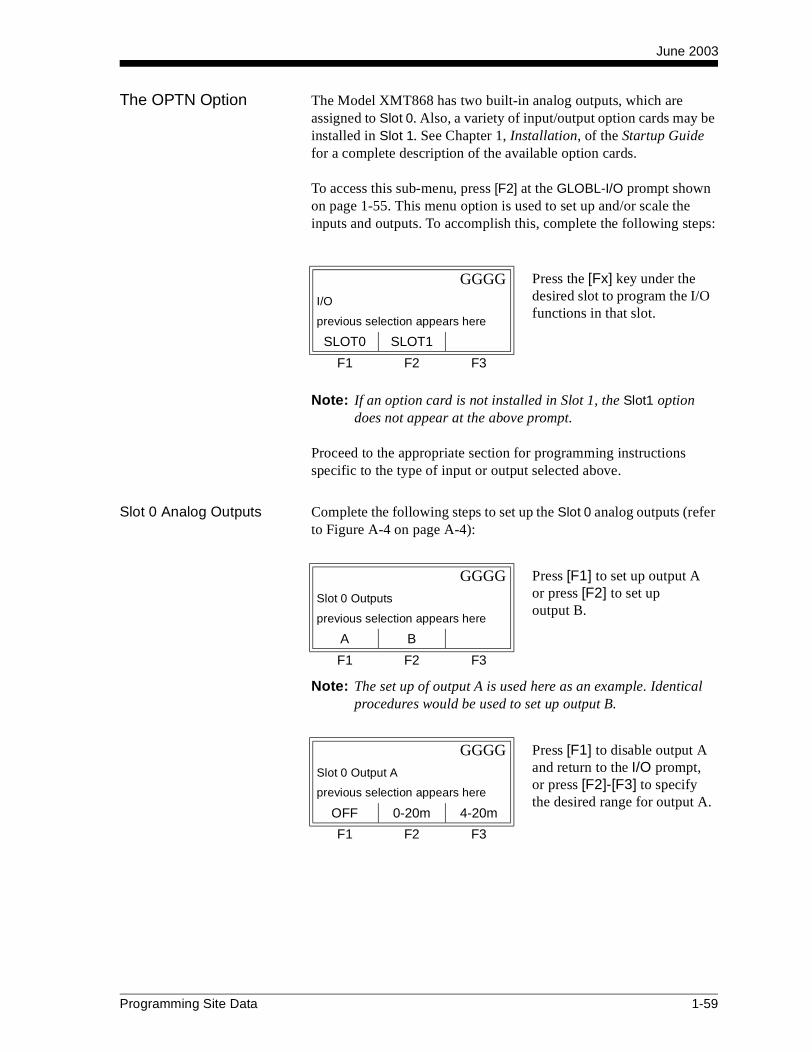
June 2003
The OPTN Option The Model XMT868 has two built-in analog outputs, which are assigned to Slot 0. Also, a variety of input/output option cards may be installed in Slot 1. See Chapter 1, Installation, of the Startup Guide for a complete description of the available option cards.
To access this sub-menu, press [F2] at the GLOBL-I/O prompt shown on page 1-55. This menu option is used to set up and/or scale the inputs and outputs. To accomplish this, complete the following steps:
Note: If an option card is not installed in Slot 1, the Slot1 option does not appear at the above prompt.
Proceed to the appropriate section for programming instructions specific to the type of input or output selected above.
Slot 0 Analog Outputs Complete the following steps to set up the Slot 0 analog outputs (refer to Figure A-4 on page A-4):
Note: The set up of output A is used here as an example. Identical procedures would be used to set up output B.
GGGG Press the [Fx] key under the desired slot to program the I/O functions in that slot.
I/O
previous selection appears here
SLOT0 SLOT1
F1 F2 F3
GGGG Press [F1] to set up output A or press [F2] to set up output B.
Slot 0 Outputs
previous selection appears here
A B
F1 F2 F3
GGGG Press [F1] to disable output A and return to the I/O prompt, or press [F2]-[F3] to specify the desired range for output A.
Slot 0 Output A
previous selection appears here
OFF 0-20m 4-20m
F1 F2 F3
Programming Site Data 1-59
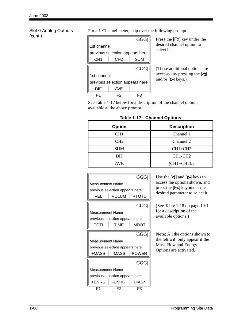
June 2003
Slot 0 Analog Outputs (cont.)
For a 1-Channel meter, skip over the following prompt.
See Table 1-17 below for a description of the channel options available at the above prompt.
GGG| Press the [Fx] key under the desired channel option to select it.
1st channel
previous selection appears here
CH1 CH2 SUM
GGG| (These additional options are accessed by pressing the [ ] and/or [ ] keys.)
1st channel
previous selection appears here
DIF AVE
F1 F2 F3
Table 1-17: Channel Options
Option Description
CH1 Channel 1
CH2 Channel 2
SUM CH1+CH2
DIF CH1-CH2
AVE (CH1+CH2)/2
GGG| Use the [ ] and [ ] keys to access the options shown, and press the [Fx] key under the desired parameter to select it.
Measurement Name
previous selection appears here
VEL VOLUM +TOTL
GGG| (See Table 1-18 on page 1-61 for a description of the available options.)
Measurement Name
previous selection appears here
-TOTL TIME MDOT
GGG| Note: All the options shown to the left will only appear if the Mass Flow and Energy Options are activated.
Measurement Name
previous selection appears here
+MASS -MASS POWER
GGG|
Measurement Name
previous selection appears here
+ENRG -ENRG DIAG*
F1 F2 F3
1-60 Programming Site Data

June 2003
Slot 0 Analog Outputs (cont.)
The DIAG* option listed in Table 1-18 above represents all of the individual diagnostic parameters that appear at the previous prompt. See Chapter 3, Diagnostics, of the Service Manual for a complete description of these options.
Note: The measurement units that appear in these prompts are those selected in the GLOBL-SYSTM menu earlier in this section.
After responding to the above prompt, the meter returns to the GLOBL-I/O prompt shown on page 1-55. To leave the User Program, press the [EXIT] key three times.
Table 1-18: Output Measurement Options
Option Bar Choice Description
[F1] = VEL Flow Velocity
[F2] = VOLUM Volumetric Flow
[F3] = +TOTL Forward Totalized Volume Flow
[ ] + [F1] = -TOTL Reverse Totalized Volume Flow
[ ] + [F2] = TIME Total Flow Measurement Time
[ ] + [F3] = MDOT Mass Flow
[ ] + [ ] + [F1] = +MASS Forward Totalized Mass Flow
[ ] + [ ] + [F2] = -MASS Reverse Totalized Mass Flow
[ ] + [ ] + [F3] = POWER Energy Flow Power
[ ] + [ ] + [ ] + [F1] = +ENRG Forward Energy Flow
[ ] + [ ] + [ ] + [F2] = -ENRG Reverse Energy Flow
[ ] + [ ] + [ ] + [F3] = DIAG* Diagnostic Parameters
GGGG Enter a flow rate value for the low end of the analog output range and press [ENT].
BASE
current value appears here
F1 F2 F3
GGGG Enter a flow rate value for the high end of the analog output range and press [ENT].
FULL
current value appears here
F1 F2 F3
Programming Site Data 1-61
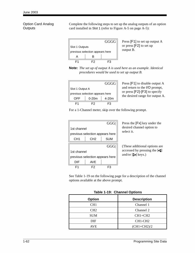
June 2003
Option Card Analog Outputs
Complete the following steps to set up the analog outputs of an option card installed in Slot 1 (refer to Figure A-5 on page A-5):
Note: The set up of output A is used here as an example. Identical procedures would be used to set up output B.
For a 1-Channel meter, skip over the following prompt.
See Table 1-19 on the following page for a description of the channel options available at the above prompt.
GGGG Press [F1] to set up output A or press [F2] to set up output B.
Slot 1 Outputs
previous selection appears here
A B
F1 F2 F3
GGGG Press [F1] to disable output A and return to the I/O prompt, or press [F2]-[F3] to specify the desired range for output A.
Slot 1 Output A
previous selection appears here
OFF 0-20m 4-20m
F1 F2 F3
GGG| Press the [Fx] key under the desired channel option to select it.
1st channel
previous selection appears here
CH1 CH2 SUM
GGG| (These additional options are accessed by pressing the [ ] and/or [ ] keys.)
1st channel
previous selection appears here
DIF AVE
F1 F2 F3
Table 1-19: Channel Options
Option Description
CH1 Channel 1
CH2 Channel 2
SUM CH1+CH2
DIF CH1-CH2
AVE (CH1+CH2)/2
1-62 Programming Site Data
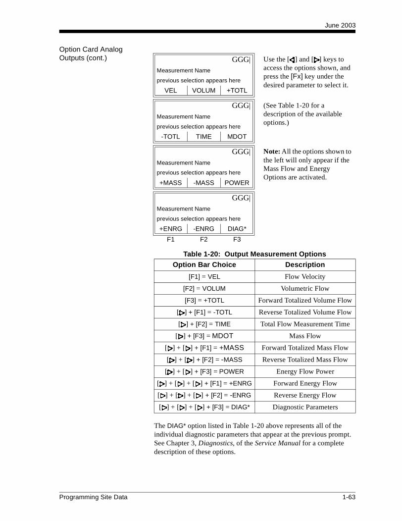
June 2003
Option Card Analog Outputs (cont.)
The DIAG* option listed in Table 1-20 above represents all of the individual diagnostic parameters that appear at the previous prompt. See Chapter 3, Diagnostics, of the Service Manual for a complete description of these options.
GGG| Use the [ ] and [ ] keys to access the options shown, and press the [Fx] key under the desired parameter to select it.
Measurement Name
previous selection appears here
VEL VOLUM +TOTL
GGG| (See Table 1-20 for a description of the available options.)
Measurement Name
previous selection appears here
-TOTL TIME MDOT
GGG| Note: All the options shown to the left will only appear if the Mass Flow and Energy Options are activated.
Measurement Name
previous selection appears here
+MASS -MASS POWER
GGG|
Measurement Name
previous selection appears here
+ENRG -ENRG DIAG*
F1 F2 F3
Table 1-20: Output Measurement Options
Option Bar Choice Description
[F1] = VEL Flow Velocity
[F2] = VOLUM Volumetric Flow
[F3] = +TOTL Forward Totalized Volume Flow
[ ] + [F1] = -TOTL Reverse Totalized Volume Flow
[ ] + [F2] = TIME Total Flow Measurement Time
[ ] + [F3] = MDOT Mass Flow
[ ] + [ ] + [F1] = +MASS Forward Totalized Mass Flow
[ ] + [ ] + [F2] = -MASS Reverse Totalized Mass Flow
[ ] + [ ] + [F3] = POWER Energy Flow Power
[ ] + [ ] + [ ] + [F1] = +ENRG Forward Energy Flow
[ ] + [ ] + [ ] + [F2] = -ENRG Reverse Energy Flow
[ ] + [ ] + [ ] + [F3] = DIAG* Diagnostic Parameters
Programming Site Data 1-63
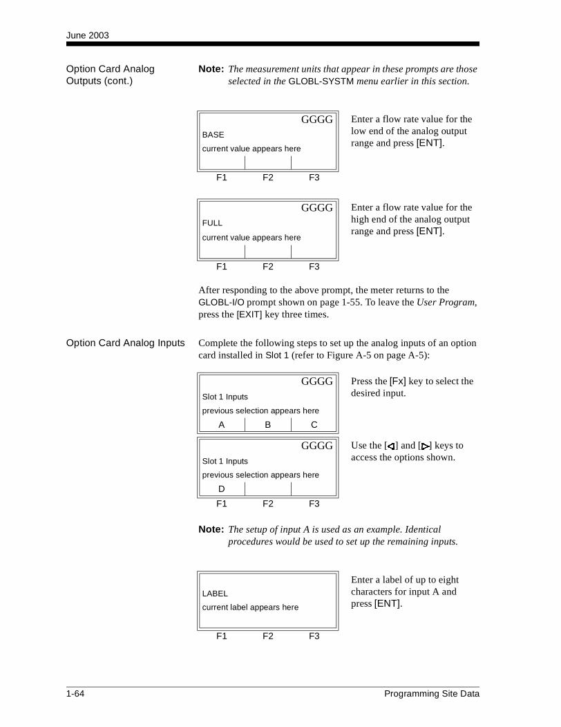
June 2003
Option Card Analog Outputs (cont.)
Note: The measurement units that appear in these prompts are those selected in the GLOBL-SYSTM menu earlier in this section.
After responding to the above prompt, the meter returns to the GLOBL-I/O prompt shown on page 1-55. To leave the User Program, press the [EXIT] key three times.
Option Card Analog Inputs Complete the following steps to set up the analog inputs of an option card installed in Slot 1 (refer to Figure A-5 on page A-5):
Note: The setup of input A is used as an example. Identical procedures would be used to set up the remaining inputs.
GGGG Enter a flow rate value for the low end of the analog output range and press [ENT].
BASE
current value appears here
F1 F2 F3
GGGG Enter a flow rate value for the high end of the analog output range and press [ENT].
FULL
current value appears here
F1 F2 F3
GGGG Press the [Fx] key to select the desired input.Slot 1 Inputs
previous selection appears here
A B C
GGGG Use the [ ] and [ ] keys to access the options shown.Slot 1 Inputs
previous selection appears here
D
F1 F2 F3
Enter a label of up to eight characters for input A and press [ENT].
LABEL
current label appears here
F1 F2 F3
1-64 Programming Site Data
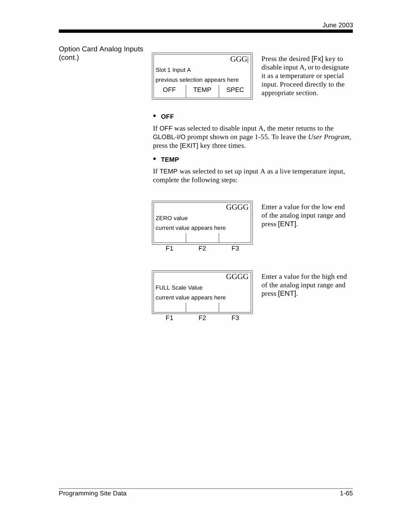
June 2003
Option Card Analog Inputs (cont.)
• OFF
If OFF was selected to disable input A, the meter returns to the GLOBL-I/O prompt shown on page 1-55. To leave the User Program, press the [EXIT] key three times.
• TEMP
If TEMP was selected to set up input A as a live temperature input, complete the following steps:
GGG| Press the desired [Fx] key to disable input A, or to designate it as a temperature or special input. Proceed directly to the appropriate section.
Slot 1 Input A
previous selection appears here
OFF TEMP SPEC
GGGG Enter a value for the low end of the analog input range and press [ENT].
ZERO value
current value appears here
F1 F2 F3
GGGG Enter a value for the high end of the analog input range and press [ENT].
FULL Scale Value
current value appears here
F1 F2 F3
Programming Site Data 1-65

June 2003
Option Card Analog Inputs (cont.)
After responding to the above prompt, the meter returns to the GLOBL-I/O prompt shown on page 1-55. To leave the User Program, press the [EXIT] key three times.
• SPEC
If SPEC was selected to set up input A as a live special input, complete the following steps:
After responding to the above prompt, the meter returns to the GLOBL-I/O prompt shown on page 1-55. To leave the User Program, press the [EXIT] key three times.
Enter a name for input A and press [ENT].INPUT NAME
current name appears here
F1 F2 F3
Enter a unit of measurement for input A and press [ENT].INPUT UNITS
current units appears here
F1 F2 F3
GGGG Enter a temperature value for the low end of the analog input range and press [ENT].
ZERO value
current value appears here
F1 F2 F3
GGGG Enter a temperature value for the high end of the analog input range and press [ENT].
FULL Scale Value
current value appears here
F1 F2 F3
1-66 Programming Site Data

June 2003
Option Card RTD Inputs Option cards with RTD inputs have a temperature range of -148o to
660oF (–100° to 350°C). Complete the following steps to set up the RTD inputs of an option card installed in Slot 1 (refer to Figure A-5 on page A-5):
Note: The setup of RTD input A is used here as an example. Identical procedures would be used to set up the remaining RTD inputs.
GGGG Use the [ ] and [ ] keys to access the options shown, and press the [Fx] key to select the desired RTD input.
Slot 1 Outputs
previous selection appears here
A B C
GGGGSlot 1 Outputs
previous selection appears here
D
F1 F2 F3
Enter a label of up to eight characters for RTD input A and press [ENT].
LABEL
current label appears here
F1 F2 F3
GGGG Press [F1] to disable input A and return to the GLOBL-I/O prompt on page 1-55, or press [F2] to enable input A as a live temperature input.
Slot 1 Input A
previous selection appears here
OFF TEMP
F1 F2 F3
GGGG Enter a temperature value for the low end of the analog input range and press [ENT].
ZERO value
current value appears here
F1 F2 F3
Programming Site Data 1-67
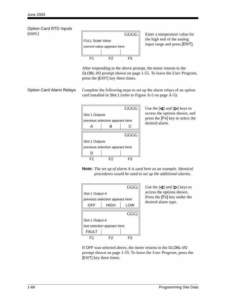
June 2003
Option Card RTD Inputs (cont.)
After responding to the above prompt, the meter returns to the GLOBL-I/O prompt shown on page 1-55. To leave the User Program, press the [EXIT] key three times.
Option Card Alarm Relays Complete the following steps to set up the alarm relays of an option card installed in Slot 1 (refer to Figure A-5 on page A-5):
Note: The set up of alarm A is used here as an example. Identical procedures would be used to set up the additional alarms.
If OFF was selected above, the meter returns to the GLOBL-I/O prompt shown on page 1-55. To leave the User Program, press the [EXIT] key three times.
GGGG Enter a temperature value for the high end of the analog input range and press [ENT].
FULL Scale Value
current value appears here
F1 F2 F3
GGGG Use the [ ] and [ ] keys to access the options shown, and press the [Fx] key to select the desired alarm.
Slot 1 Outputs
previous selection appears here
A B C
GGGGSlot 1 Outputs
previous selection appears here
D
F1 F2 F3
GGG| Use the [ ] and [ ] keys to access the options shown. Press the [Fx] key under the desired alarm type.
Slot 1 Output A
previous selection appears here
OFF HIGH LOW
GGG|
Slot 1 Output A
last selection appears here
FAULT
F1 F2 F3
1-68 Programming Site Data

June 2003
Option Card Alarm Relays (cont.)
For a 1-Channel meter, skip over the following prompt.
See Table 1-21 below for a description of the channel options available at the above prompt.
Note: If FAULT was selected as the alarm type, the next two prompts do not appear. Skip over them to the end of this section.
GGGG Press [F1] for standard operation or [F2] for fail-safe operation. See Chapter 1, Installation, of the Startup Guide for wiring instructions.
Failsafe?
previous selection appears here
NO YES
F1 F2 F3
GGG| Press the [Fx] key under the desired channel option to select it.
1st channel
previous selection appears here
CH1 CH2 SUM
GGG| (These additional options are accessed by pressing the [ ] and/or [ ] keys.)
1st channel
previous selection appears here
DIF AVE
F1 F2 F3
Table 1-21: Channel Options
Option Description
CH1 Channel 1
CH2 Channel 2
SUM CH1+CH2
DIF CH1-CH2
AVE (CH1+CH2)/2
Programming Site Data 1-69
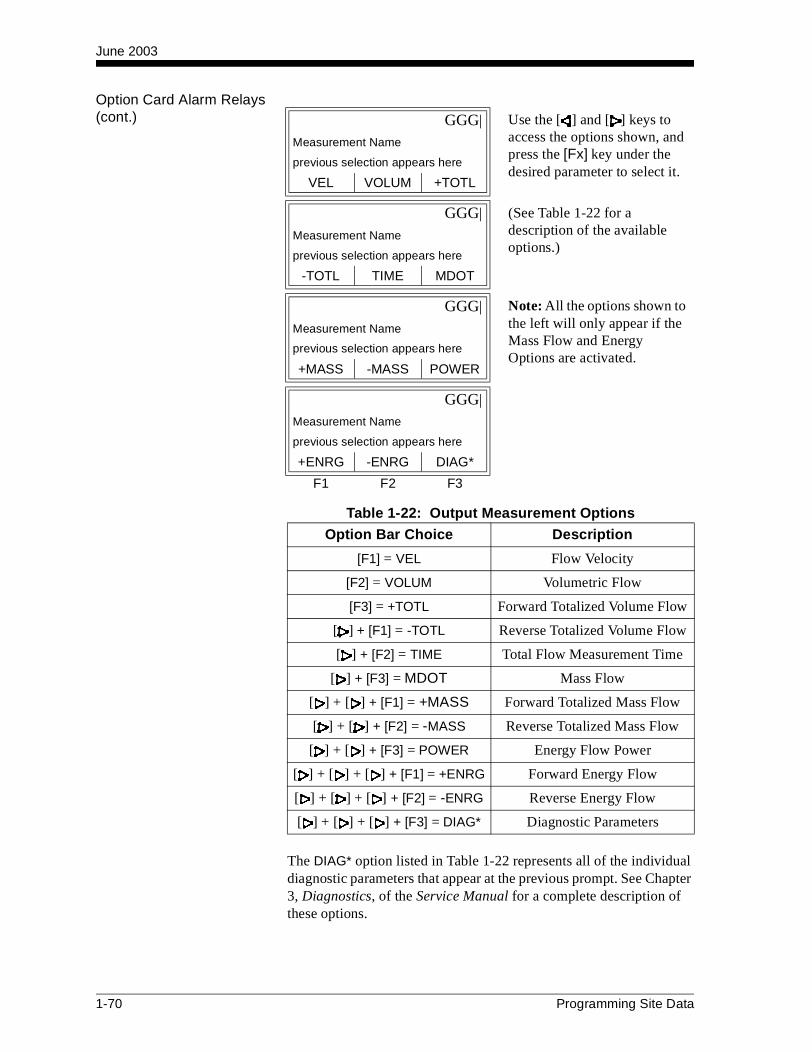
June 2003
Option Card Alarm Relays (cont.)
The DIAG* option listed in Table 1-22 represents all of the individual diagnostic parameters that appear at the previous prompt. See Chapter 3, Diagnostics, of the Service Manual for a complete description of these options.
GGG| Use the [ ] and [ ] keys to access the options shown, and press the [Fx] key under the desired parameter to select it.
Measurement Name
previous selection appears here
VEL VOLUM +TOTL
GGG| (See Table 1-22 for a description of the available options.)
Measurement Name
previous selection appears here
-TOTL TIME MDOT
GGG| Note: All the options shown to the left will only appear if the Mass Flow and Energy Options are activated.
Measurement Name
previous selection appears here
+MASS -MASS POWER
GGG|
Measurement Name
previous selection appears here
+ENRG -ENRG DIAG*
F1 F2 F3
Table 1-22: Output Measurement Options
Option Bar Choice Description
[F1] = VEL Flow Velocity
[F2] = VOLUM Volumetric Flow
[F3] = +TOTL Forward Totalized Volume Flow
[ ] + [F1] = -TOTL Reverse Totalized Volume Flow
[ ] + [F2] = TIME Total Flow Measurement Time
[ ] + [F3] = MDOT Mass Flow
[ ] + [ ] + [F1] = +MASS Forward Totalized Mass Flow
[ ] + [ ] + [F2] = -MASS Reverse Totalized Mass Flow
[ ] + [ ] + [F3] = POWER Energy Flow Power
[ ] + [ ] + [ ] + [F1] = +ENRG Forward Energy Flow
[ ] + [ ] + [ ] + [F2] = -ENRG Reverse Energy Flow
[ ] + [ ] + [ ] + [F3] = DIAG* Diagnostic Parameters
1-70 Programming Site Data

June 2003
Option Card Alarm Relays (cont.)
Note: The measurement units that appear in these prompts are those selected in the GLOBL-SYSTM menu earlier in this section.
After responding to the above prompt, or if FAULT was selected as the alarm type, the meter returns to the GLOBL-I/O prompt shown on page 1-55. To leave the User Program, press the [EXIT] key three times.
Option Card Totalizer Outputs
This type of output issues one pulse per selected volume of flow. The meter produces a pulse each time the programmed amount of flow passes through the pipe. Complete the following steps to set up the totalizer outputs of an option card installed in Slot 1:
Note: The set up of output A is used as an example. Identical procedures would be used to set up the other outputs.
If OFF was selected above, the meter returns to the GLOBL-I/O prompt shown on page 1-55. To leave the User Program, press the [EXIT] key three times.
GGGG Enter a value for the trigger point of the alarm and press [ENT].
Trigger point
current value appears here
F1 F2 F3
GGGG Use the [ ] and [ ] keys to access the options shown. Press the [Fx] key under the desired totalizer.
Slot 1 Outputs
previous selection appears here
A B C
GGGGSlot 1 Outputs
previous selection appears here
D
F1 F2 F3
GGGG Press [F1] to disable output A, or press [F2] to set up output A as a totalizer output.
Slot 1 Output A
previous selection appears here
OFF TTLZR
F1 F2 F3
Programming Site Data 1-71

June 2003
Option Card Totalizer Outputs (cont.)
For a 1-Channel meter, skip over the following prompt.
See Table 1-23 on the following page for a description of the channel options available at the above prompt.
GGG| Press the [Fx] key under the desired channel option to select it.
1st channel
previous selection appears here
CH1 CH2 SUM
GGG| (These additional options are accessed by pressing the [ ] and/or [ ] keys.)
1st channel
previous selection appears here
DIF AVE
F1 F2 F3
Table 1-23: Channel Options
Option Description
CH1 Channel 1
CH2 Channel 2
SUM CH1+CH2
DIF CH1-CH2
AVE (CH1+CH2)/2
GGG| Use the [ ] and [ ] keys to access the options shown, and press the [Fx] key under the desired parameter to select it.
Measurement Name
previous selection appears here
+TOTL -TOTL +MASS
GGG| (See Table 1-24 on the next page for a description of the available options.)
Measurement Name
previous selection appears here
-MASS +ENRG -ENRG
F1 F2 F3
1-72 Programming Site Data

June 2003
Option Card Totalizer Outputs (cont.)
Note: The measurement units that appear in these prompts are those selected in the GLOBL-SYSTM menu earlier in this section.
Note: A complete pulse consists of equal amounts of ON and OFF times. Choose a value that is compatible with the counter to be used.
After responding to the above prompt, the meter returns to the GLOBL-I/O prompt shown on page 1-55. To leave the User Program, press the [EXIT] key three times.
Table 1-24: Output Measurement Options
Option Bar Choice Description
[F1] = +TOTL Forward Totalized Volume Flow
[F2] = -TOTL Reverse Totalized Volume Flow
[F3] = +MASS Forward Totalized Mass Flow
[ ] + [F1] = -MASS Reverse Totalized Mass Flow
[ ] + [F2] = +ENRG Forward Energy
[ ] + [F3] = -ENRG Reverse Energy
GGGG Enter a value between 50 µsec and 500,000 µsec for the frequency of the totalizer pulses and press [ENT].
PULSE ON TIME
current value appears here
F1 F2 F3
GGGG Enter a value for the number of measurement units represented by each pulse, and press [ENT].
UNITS/PULSE
current value appears here
F1 F2 F3
Programming Site Data 1-73

June 2003
Option Card Frequency Outputs
This type of output produces a frequency pulse that is proportional to the output measurement. Complete the following steps to set up the frequency outputs of an option card installed in Slot 1 (refer to Figure A-5 on page A-5):
Note: The set up of output A is used as an example. Identical procedures would be used to set up the other outputs.
If OFF was selected above, the meter returns to the GLOBL-I/O prompt shown on page 1-55. To leave the User Program, press the [EXIT] key three times.
For a 1-Channel meter, skip over the following prompt.
GGGG Use the [ ] and [ ] keys to access the options shown. Press the [Fx] key under the desired frequency output.
Slot 1 Outputs
previous selection appears here
A B C
GGGGSlot 1 Outputs
previous selection appears here
D
F1 F2 F3
GGGG Press [F1] to disable output A, or press [F2] to set up output A as a frequency output.
Slot 1 Output A
previous selection appears here
OFF FREQ
F1 F2 F3
GGG| Press the [Fx] key under the desired channel option to select it.
1st channel
previous selection appears here
CH1 CH2 SUM
GGG| (These additional options are accessed by pressing the [ ] and/or [ ] keys.)
1st channel
previous selection appears here
DIF AVE
F1 F2 F3
1-74 Programming Site Data

June 2003
Option Card Frequency Outputs (cont.)
See Table 1-25 below for a description of the channel options available at the above prompt.
Table 1-25: Channel Options
Option Description
CH1 Channel 1
CH2 Channel 2
SUM CH1+CH2
DIF CH1-CH2
AVE (CH1+CH2)/2
GGG| Use the [ ] and [ ] keys to access the options shown, and press the [Fx] key under the desired parameter to select it.
Measurement Name
previous selection appears here
VEL VOLUM +TOTL
GGG| (See Table 1-26 for a description of the available options.)
Measurement Name
previous selection appears here
-TOTL TIME MDOT
GGG| Note: All the options shown to the left will only appear if the Mass Flow and Energy Options are activated.
Measurement Name
previous selection appears here
+MASS -MASS POWER
GGG|
Measurement Name
previous selection appears here
+ENRG -ENRG DIAG*
F1 F2 F3
Programming Site Data 1-75
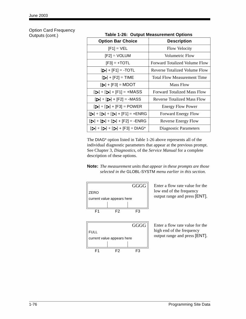
June 2003
Option Card Frequency Outputs (cont.)
The DIAG* option listed in Table 1-26 above represents all of the individual diagnostic parameters that appear at the previous prompt. See Chapter 3, Diagnostics, of the Service Manual for a complete description of these options.
Note: The measurement units that appear in these prompts are those selected in the GLOBL-SYSTM menu earlier in this section.
Table 1-26: Output Measurement Options
Option Bar Choice Description
[F1] = VEL Flow Velocity
[F2] = VOLUM Volumetric Flow
[F3] = +TOTL Forward Totalized Volume Flow
[ ] + [F1] = -TOTL Reverse Totalized Volume Flow
[ ] + [F2] = TIME Total Flow Measurement Time
[ ] + [F3] = MDOT Mass Flow
[ ] + [ ] + [F1] = +MASS Forward Totalized Mass Flow
[ ] + [ ] + [F2] = -MASS Reverse Totalized Mass Flow
[ ] + [ ] + [F3] = POWER Energy Flow Power
[ ] + [ ] + [ ] + [F1] = +ENRG Forward Energy Flow
[ ] + [ ] + [ ] + [F2] = -ENRG Reverse Energy Flow
[ ] + [ ] + [ ] + [F3] = DIAG* Diagnostic Parameters
GGGG Enter a flow rate value for the low end of the frequency output range and press [ENT].
ZERO
current value appears here
F1 F2 F3
GGGG Enter a flow rate value for the high end of the frequency output range and press [ENT].
FULL
current value appears here
F1 F2 F3
1-76 Programming Site Data
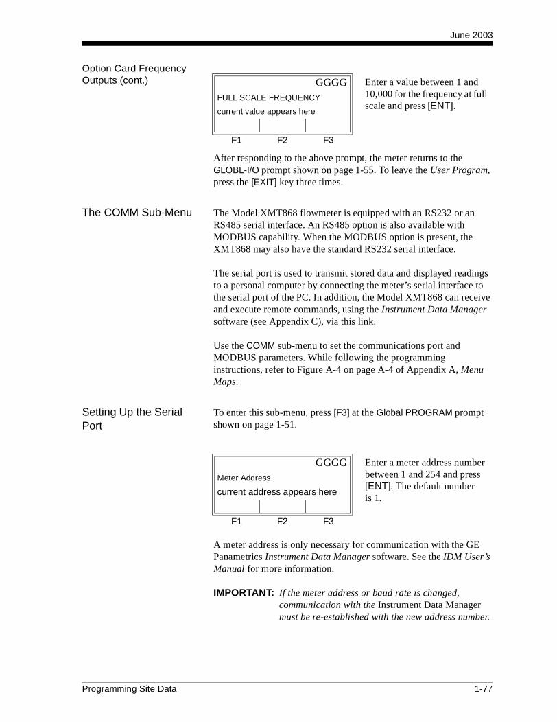
June 2003
Option Card Frequency Outputs (cont.)
After responding to the above prompt, the meter returns to the GLOBL-I/O prompt shown on page 1-55. To leave the User Program, press the [EXIT] key three times.
The COMM Sub-Menu The Model XMT868 flowmeter is equipped with an RS232 or an RS485 serial interface. An RS485 option is also available with MODBUS capability. When the MODBUS option is present, the XMT868 may also have the standard RS232 serial interface.
The serial port is used to transmit stored data and displayed readings to a personal computer by connecting the meter’s serial interface to the serial port of the PC. In addition, the Model XMT868 can receive and execute remote commands, using the Instrument Data Manager software (see Appendix C), via this link.
Use the COMM sub-menu to set the communications port and MODBUS parameters. While following the programming instructions, refer to Figure A-4 on page A-4 of Appendix A, Menu Maps.
Setting Up the Serial Port
To enter this sub-menu, press [F3] at the Global PROGRAM prompt shown on page 1-51.
A meter address is only necessary for communication with the GE Panametrics Instrument Data Manager software. See the IDM User’s Manual for more information.
IMPORTANT: If the meter address or baud rate is changed, communication with the Instrument Data Manager must be re-established with the new address number.
GGGG Enter a value between 1 and 10,000 for the frequency at full scale and press [ENT].
FULL SCALE FREQUENCY
current value appears here
F1 F2 F3
GGGG Enter a meter address number between 1 and 254 and press [ENT]. The default numberis 1.
Meter Address
current address appears here
F1 F2 F3
Programming Site Data 1-77

June 2003
Setting Up the Serial Port (cont.)
If you have the RS485 MODBUS option, proceed to the prompts below. If you have the standard RS232 serial interface, the meter exits the COMM sub-menu and returns to the Global PROGRAM prompt. To leave the User Program, press the [EXIT] key twice.
Note: The XMT868 MODBUS communication settings chosen in the next four steps must match those of the MODBUS control system.
GGG| Use the [ ] and [ ] keys to access the options shown, and press the [Fx] key under the desired baud rate to select it.
BAUD RATE
current value appears here
300 600 1200
GGG|
BAUD RATE
current value appears here
2400 4800 9600
GGG|
BAUD RATE
current value appears here
19200
F1 F2 F3
GGG| Press the [Fx] key under the desired MODBUS baud rate to select it.
MODBUS BAUD RATE
current value appears here
2400 4800 9600
F1 F2 F3
GGG| Press the [Fx] key under the desired MODBUS parity to select it.
MODBUS PARITY
current value appears here
NONE ODD EVEN
F1 F2 F3
1-78 Programming Site Data

June 2003
Setting Up the Serial Port (cont.)
The meter exits the COMM sub-menu and returns to the Global PROGRAM prompt. To leave the User Program, press the [EXIT] key twice.
IMPORTANT: You must reboot the XMT868 to load the new settings.
Refer to the section Requesting Parameters Using MODBUS on the following page to retrieve data from the XMT868 using MODBUS.
GGG| Press the [Fx] key under the desired MODBUS stop bits to select it.
MODBUS STOP BITS
current value appears here
1 BIT 2 BITS
F1 F2 F3
GGG| Press the [Fx] key under the desired MODBUS address to select it.
MODBUS ADDRESS
current value appears here
F1 F2 F3
Programming Site Data 1-79
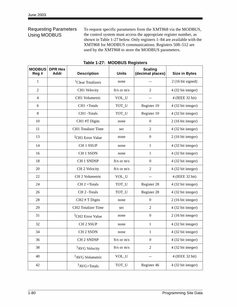
June 2003
Requesting Parameters Using MODBUS
To request specific parameters from the XMT868 via the MODBUS, the control system must access the appropriate register number, as shown in Table 1-27 below. Only registers 1–84 are available with the XMT868 for MODBUS communications. Registers 508–512 are used by the XMT868 to store the MODBUS parameters.
:Table 1-27: MODBUS Registers
MODBUS Reg #
DPR Hex Addr Description Units
Scaling(decimal places) Size in Bytes
1 1Clear Totalizers none -- 2 (16 bit signed)
2 CH1 Velocity ft/s or m/s 2 4 (32 bit integer)
4 CH1 Volumetric VOL_U -- 4 (IEEE 32 bit)
6 CH1 +Totals TOT_U Register 10 4 (32 bit integer)
8 CH1 -Totals TOT_U Register 10 4 (32 bit integer)
10 CH1 #T Digits none 0 2 (16 bit integer)
11 CH1 Totalizer Time sec 2 4 (32 bit integer)
13 2CH1 Error Value none 0 2 (16 bit integer)
14 CH 1 SSUP none 1 4 (32 bit integer)
16 CH 1 SSDN none 1 4 (32 bit integer)
18 CH 1 SNDSP ft/s or m/s 0 4 (32 bit integer)
20 CH 2 Velocity ft/s or m/s 2 4 (32 bit integer)
22 CH 2 Volumetric VOL_U -- 4 (IEEE 32 bit)
24 CH 2 +Totals TOT_U Register 28 4 (32 bit integer)
26 CH 2 -Totals TOT_U Register 28 4 (32 bit integer)
28 CH2 # T Digits none 0 2 (16 bit integer)
29 CH2 Totalizer Time sec 2 4 (32 bit integer)
31 2CH2 Error Value none 0 2 (16 bit integer)
32 CH 2 SSUP none 1 4 (32 bit integer)
34 CH 2 SSDN none 1 4 (32 bit integer)
36 CH 2 SNDSP ft/s or m/s 0 4 (32 bit integer)
38 3AVG Velocity ft/s or m/s 2 4 (32 bit integer)
40 3AVG Volumetric VOL_U -- 4 (IEEE 32 bit)
42 3AVG+Totals TOT_U Register 46 4 (32 bit integer)
1-80 Programming Site Data
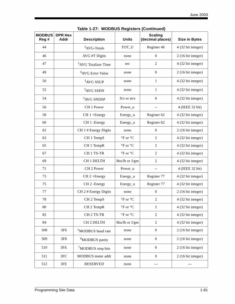
June 2003
MODBUS Reg #
DPR Hex Addr Description Units
Scaling(decimal places) Size in Bytes
44 3AVG-Totals TOT_U Register 46 4 (32 bit integer)
46 AVG #T Digits none 0 2 (16 bit integer)
47 3AVG Totalizer Time sec 2 4 (32 bit integer)
49 4AVG Error Value none 0 2 (16 bit integer)
50 3AVG SSUP none 1 4 (32 bit integer)
52 3AVG SSDN none 1 4 (32 bit integer)
54 3AVG SNDSP ft/s or m/s 0 4 (32 bit integer)
56 CH 1 Power Power_u -- 4 (IEEE 32 bit)
58 CH 1 +Energy Energy_u Register 62 4 (32 bit integer)
60 CH 1 -Energy Energy_u Register 62 4 (32 bit integer)
62 CH 1 # Energy Digits none 0 2 (16 bit integer)
63 CH 1 TempS °F or °C 2 4 (32 bit integer)
65 CH 1 TempR °F or °C 2 4 (32 bit integer)
67 CH 1 TS-TR °F or °C 2 4 (32 bit integer)
69 CH 1 DELTH Btu/lb or J/gm 2 4 (32 bit integer)
71 CH 2 Power Power_u -- 4 (IEEE 32 bit)
73 CH 2 +Energy Energy_u Register 77 4 (32 bit integer)
75 CH 2 -Energy Energy_u Register 77 4 (32 bit integer)
77 CH 2 # Energy Digits none 0 2 (16 bit integer)
78 CH 2 TempS °F or °C 2 4 (32 bit integer)
80 CH 2 TempR °F or °C 2 4 (32 bit integer)
82 CH 2 TS-TR °F or °C 2 4 (32 bit integer)
84 CH 2 DELTH Btu/lb or J/gm 2 4 (32 bit integer)
508 3F6 5MODBUS baud rate none 0 2 (16 bit integer)
509 3F8 6MODBUS parity none 0 2 (16 bit integer)
510 3FA 7MODBUS stop bits none 0 2 (16 bit integer)
511 3FC MODBUS meter addr none 0 2 (16 bit integer)
512 3FE RESERVED none --- ---
Table 1-27: MODBUS Registers (Continued)
Programming Site Data 1-81
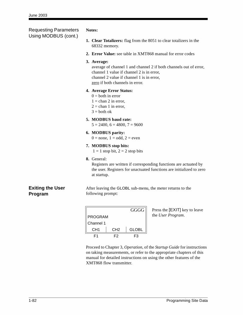
June 2003
Requesting Parameters Using MODBUS (cont.)
Notes:
1. Clear Totalizers: flag from the 8051 to clear totalizers in the 68332 memory.
2. Error Value: see table in XMT868 manual for error codes
3. Average:average of channel 1 and channel 2 if both channels out of error, channel 1 value if channel 2 is in error, channel 2 value if channel 1 is in error, zero if both channels in error.
4. Average Error Status:0 = both in error1 = chan 2 in error,2 = chan 1 in error,3 = both ok
5. MODBUS baud rate:5 = 2400, 6 = 4800, 7 = 9600
6. MODBUS parity:0 = none, 1 = odd, 2 = even
7. MODBUS stop bits: 1 = 1 stop bit, 2 = 2 stop bits
8. General:Registers are written if corresponding functions are actuated by the user. Registers for unactuated functions are initialized to zero at startup.
Exiting the User Program
After leaving the GLOBL sub-menu, the meter returns to the following prompt:
Proceed to Chapter 3, Operation, of the Startup Guide for instructions on taking measurements, or refer to the appropriate chapters of this manual for detailed instructions on using the other features of the XMT868 flow transmitter.
GGGG Press the [EXIT] key to leave the User Program.PROGRAM
Channel 1
CH1 CH2 GLOBL
F1 F2 F3
1-82 Programming Site Data

Chapter 2
Displaying Data
Introduction . . . . . . . . . . . . . . . . . . . . . . . . . . . . . . . . . . . . . . . . . . .2-1
Displaying Data with the LCD . . . . . . . . . . . . . . . . . . . . . . . . . . . . .2-1
Displaying Data with the RCCU . . . . . . . . . . . . . . . . . . . . . . . . . . .2-6
Displaying Data on a Computer Terminal . . . . . . . . . . . . . . . . . . .2-9

June 2003
Introduction This chapter explains how to display measurement data using each of the three available methods:
• LCD Display - show data on an optional built-in display
• RCCU - display data on the optional Remote Control Communications Unit (RCCU)
• IDM - display data on a computer terminal using the optional Instrument Data Manager (IDM) software
Displaying Data with the LCD
If the Model XMT868 flow transmitter is equipped with the optional Liquid Crystal Display (LCD), it may be programmed to display up to four variables in sequence. In addition, both the brightness and the contrast of the LCD may be adjusted for optimum viewing. Proceed to the appropriate section for instructions.
Adjusting LCD Contrast and Brightness
Both the contrast and the brightness of the optional LCD may be adjusted to suit individual needs. As shown in the upper right view of Figure 4-3 on page 4-15 of the Service Manual, there are two 3/4-turn adjustment potentiometers located on the LCD circuit board. Using these pots for the LCD adjustment, complete the following steps:
!WARNING!Never remove the covers from the XMT868 in a
hazardous environment, while the line power is on.
1. Make sure the XMT868 is in a safe environment, and loosen the set screw to remove the front cover (see Chapter 4, Parts Replacement, in the Service Manual for details, if necessary).
IMPORTANT: If the XMT868 is to be installed in a hazardous environment, adjust the LCD brightness and contrast in a safe area, before mounting the enclosure.
2. With power still applied to the meter, carefully use a small screwdriver to adjust the LCD brightness. Turning the BKLT (backlight) pot fully clockwise yields maximum brightness.
3. In a similar manner, adjust the CONT (contrast) pot to set the LCD contrast as desired. At either extreme of the CONT pot, the display is unreadable; turn the pot fully counterclockwise and then turn it clockwise very slowly until the display is clear.
Displaying Data 2-1
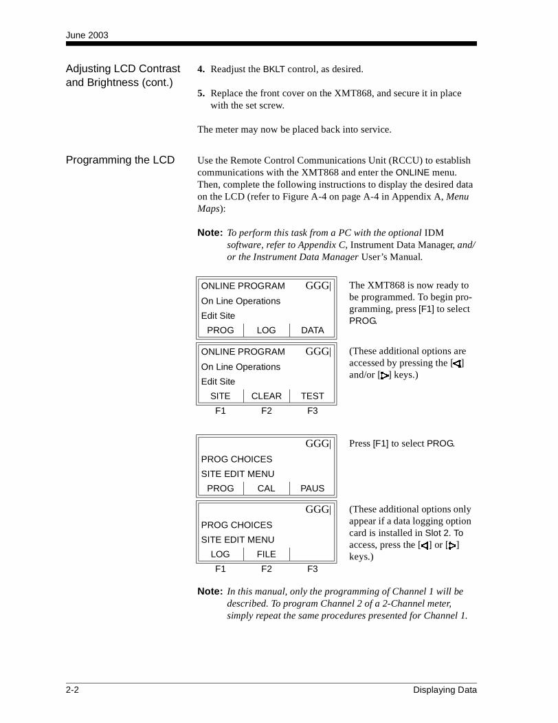
June 2003
Adjusting LCD Contrast and Brightness (cont.)
4. Readjust the BKLT control, as desired.
5. Replace the front cover on the XMT868, and secure it in place with the set screw.
The meter may now be placed back into service.
Programming the LCD Use the Remote Control Communications Unit (RCCU) to establish communications with the XMT868 and enter the ONLINE menu. Then, complete the following instructions to display the desired data on the LCD (refer to Figure A-4 on page A-4 in Appendix A, Menu Maps):
Note: To perform this task from a PC with the optional IDM software, refer to Appendix C, Instrument Data Manager, and/or the Instrument Data Manager User’s Manual.
Note: In this manual, only the programming of Channel 1 will be described. To program Channel 2 of a 2-Channel meter, simply repeat the same procedures presented for Channel 1.
ONLINE PROGRAM GGG| The XMT868 is now ready to be programmed. To begin pro-gramming, press [F1] to select PROG.
On Line Operations
Edit Site
PROG LOG DATA
ONLINE PROGRAM GGG| (These additional options are accessed by pressing the [ ] and/or [ ] keys.)
On Line Operations
Edit Site
SITE CLEAR TEST
F1 F2 F3
GGG| Press [F1] to select PROG.
PROG CHOICES
SITE EDIT MENU
PROG CAL PAUS
GGG| (These additional options only appear if a data logging option card is installed in Slot 2. To access, press the [ ] or [ ] keys.)
PROG CHOICES
SITE EDIT MENU
LOG FILE
F1 F2 F3
2-2 Displaying Data

June 2003
Programming the LCD (cont.)
At this point, a series of additional prompts permits the LCD to be configured as desired:
Note: The XMT868 refers to the parameters specified above as1st channel, 2nd channel, 3rd channel and 4th channel.
For a 1-Channel XMT868, the data for Channel 1 is displayed automatically. However, for a 2-Channel meter, the channel data to be displayed must be specified at the following prompt.
GGGG Press the [Fx] under GLOBL to select it. (Note that the CH2 option does not appear for a one-channel meter.)
PROGRAM
previous selection appears here
CH1 CH2 GLOBL
F1 F2 F3
GGGG Press [F2] to select I/O.
Global PROGRAM
previous selection appears here
SYSTM I/O COMM
F1 F2 F3
GGGG Press [F3] to select LCD.
Global I/O
previous selection appears here
ERROR OPTN LCD
F1 F2 F3
GGG| Press the [Fx] key under the desired number of parameters to be sequentially displayed.
# OF LCD PARAMS
previous selection appears here
OFF 1 2
GGG| (These additional options are accessed by pressing the [ ] and/or [ ] keys.)
# OF LCD PARAMS
previous selection appears here
3 4
F1 F2 F3
Displaying Data 2-3
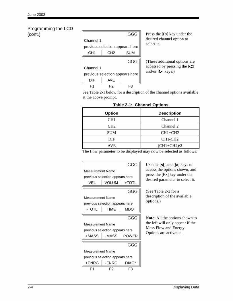
June 2003
Programming the LCD (cont.)
See Table 2-1 below for a description of the channel options available at the above prompt.
The flow parameter to be displayed may now be selected as follows:
GGG| Press the [Fx] key under the desired channel option to select it.
Channel 1
previous selection appears here
CH1 CH2 SUM
GGG| (These additional options are accessed by pressing the [ ] and/or [ ] keys.)
Channel 1
previous selection appears here
DIF AVE
F1 F2 F3
Table 2-1: Channel Options
Option Description
CH1 Channel 1
CH2 Channel 2
SUM CH1+CH2
DIF CH1-CH2
AVE (CH1+CH2)/2
GGG| Use the [ ] and [ ] keys to access the options shown, and press the [Fx] key under the desired parameter to select it.
Measurement Name
previous selection appears here
VEL VOLUM +TOTL
GGG| (See Table 2-2 for a description of the available options.)
Measurement Name
previous selection appears here
-TOTL TIME MDOT
GGG| Note: All the options shown to the left will only appear if the Mass Flow and Energy Options are activated.
Measurement Name
previous selection appears here
+MASS -MASS POWER
GGG|
Measurement Name
previous selection appears here
+ENRG -ENRG DIAG*
F1 F2 F3
2-4 Displaying Data

June 2003
Programming the LCD (cont.)
Table 2-2 below describes the display parameters that are available at the previous prompt
The DIAG* option listed in Table 2-2 above represents all of the individual diagnostic parameters that appear at the previous prompt. See Chapter 3, Diagnostics, of the Service Manual for a complete description of these options.
Note: The measurement units that appear in these prompts are those selected in the GLOBL-SYSTM menu earlier in this section.
The previous two prompts repeat until all of the specified # OF LCD PARAMS have been set up. When all of the display parameters have been set up, the meter returns to the Global I/O prompt. To leave the User Program, press the [EXIT] key three times.
After leaving the User Program, the XMT868 will reset itself and will begin to display the parameters specified in this section. If more than one parameter was set up, each of the parameters will be displayed in sequence, with a pause of several seconds between display changes.
Table 2-2: Display Parameter Options
Available Choice Description
[F1] = VEL Flow Velocity
[F2] = VOLUM Volumetric Flow
[F3] = +TOTL Forward Totalized Volume Flow
[ ] + [F1] = -TOTL Reverse Totalized Volume Flow
[ ] + [F2] = TIME Total Flow Measurement Time
[ ] + [F3] = MDOT Mass Flow
[ ] + [ ] + [F1] = +MASS Forward Totalized Mass Flow
[ ] + [ ] + [F2] = -MASS Reverse Totalized Mass Flow
[ ] + [ ] + [F3] = POWER Energy Flow Power
[ ] + [ ] + [ ] + [F1] = +ENRG Forward Energy Flow
[ ] + [ ] + [ ] + [F2] = -ENRG Reverse Energy Flow
[ ] + [ ] + [ ] + [F3] = DIAG* Diagnostic Parameters
Displaying Data 2-5

June 2003
Displaying Data with the RCCU
Using the optional Remote Control Communications Unit (RCCU), flow rate data and diagnostic parameters may be displayed. To access and program this display, complete the following steps:
Establish a link between the Remote Control Communications Unit (RCCU) and the XMT868, and enter the ONLINE menu. Then, complete the following instructions to display the desired data:
At the following prompt, specify the time span between successive flow rate readings. This is the rate at which the data display will be updated.
ONLINE PROGRAM GGG| The XMT868 is now ready to be programmed. To begin pro-gramming, press [F3] to select DATA.
On Line Operations
Edit Site
PROG LOG DATA
ONLINE PROGRAM GGG| (These additional options are accessed by pressing the [ ] and/or [ ] keys.)
On Line Operations
Edit Site
SITE CLEAR TEST
F1 F2 F3
ONLINE PROGRAM GGG| Use the [ ] and [ ] keys to find the desired flow data update rate, and press the [Fx] key under it to select it.
Live Data Update
previous selection appears here
5sec 10sec 30sec
ONLINE PROGRAM GGG|
Live Data Update
previous selection appears here
1min 3min 6min
ONLINE PROGRAM GGG|
Live Data Update
previous selection appears here
12min
F1 F2 F3
2-6 Displaying Data

June 2003
Displaying Data with the RCCU (cont.)
After specifying the flow data update rate, the channel to be displayed must be selected.
Note: The options available at the next prompt depend on how many channels of the XMT868 are currently active. For a one-channel meter, only the CH1 option appears.
IMPORTANT: Keep the RCCU pointed directly at the XMT868 throughout this programming sequence.
GGG| Use the [ ] and [ ] keys to access the options shown, and press the [Fx] key under the desired channel for display.
CHAN NAMES
previous selection appears here
CH1 CH2 SUM
GGG| (See Table 2-3 below for a description of the channel options.)
CHAN NAMES
previous selection appears here
DIF AVE
F1 F2 F3
Table 2-3: Channel Options
Option Description
CH1 Channel 1
CH2 Channel 2
SUM CH1+CH2
DIF CH1-CH2
AVE (CH1+CH2)/2
Displaying Data 2-7

June 2003
Displaying Data with the RCCU (cont.)
After the previous response has been communicated to the XMT868, the RCCU is connected to the meter by a Live Flow Link and displays the channel information specified. At this time, the flow parameter to be displayed may be selected as follows:
LIVE FLOW Link GGG| Use the [ ] and [ ] keys to find the desired flow parame-ter, and press the [Fx] key under it to select it.
previous selections appear here
current reading appears here
VEL VOLUM +TOTL
LIVE FLOW Link GGG| (See Table 2-4 below for a description of the measure-ment parameters available.)
previous selections appear here
current reading appears here
-TOTL TIME MDOT
LIVE FLOW Link GGG|
previous selections appear here
current reading appears here
+MASS -MASS POWER
LIVE FLOW Link GGG|
previous selections appear here
current reading appears here
+ENRG -ENRG DIAG*
F1 F2 F3
Table 2-4: Measurement Parameter Options
Available Choice Description
[F1] = VEL Flow Velocity
[F2] = VOLUM Volumetric Flow
[F3] = +TOTL Forward Totalized Volume Flow
[ ] + [F1] = -TOTL Reverse Totalized Volume Flow
[ ] + [F2] = TIME Total Flow Measurement Time
[ ] + [F3] = MDOT Mass Flow
[ ] + [ ] + [F1] = +MASS Forward Totalized Mass Flow
[ ] + [ ] + [F2] = -MASS Reverse Totalized Mass Flow
[ ] + [ ] + [F3] = POWER Energy Flow Power
[ ] + [ ] + [ ] + [F1] = +ENRG Forward Energy Flow
[ ] + [ ] + [ ] + [F2] = -ENRG Reverse Energy Flow
[ ] + [ ] + [ ] + [F3] = DIAG* Diagnostic Parameters
2-8 Displaying Data

June 2003
Displaying Data with the RCCU (cont.)
The DIAG* option listed in Table 2-4 above represents all of the individual diagnostic parameters that appear at the previous prompt. See Chapter 3, Diagnostics, of the Service Manual for a complete description of these options.
The display parameter may be changed from the LIVE FLOW Link prompt at any time, but changing the channel option requires that the DATA menu be reprogrammed. To accomplish this, press the [EXIT] key and repeat the instructions at the beginning of this section.
Displaying Data on a Computer Terminal
The flow rate data collected by the XMT868 may be displayed in various formats on a remote computer terminal via the meter’s RS232 serial port. This requires the use of the optional Instrument Data Manager (IDM) software. Refer to Appendix C, Instrument Data Manager, and/or the User’s Manual provided with that software for complete instructions.
IMPORTANT: The RCCU has priority in communicating with the XMT868. Therefore, IDM communications with the XMT868 will be unreliable at best, as long as an RCCU is actively linked to the meter.
Displaying Data 2-9

Chapter 3

Logging Data
Introduction . . . . . . . . . . . . . . . . . . . . . . . . . . . . . . . . . . . . . . . . . . .3-1
The Data Logging Option Card . . . . . . . . . . . . . . . . . . . . . . . . . . . .3-1
Accessing the XMT868 LOG Menu . . . . . . . . . . . . . . . . . . . . . . . . .3-1
Setting Up a Standard Log . . . . . . . . . . . . . . . . . . . . . . . . . . . . . . .3-2
Setting Up an Error Log. . . . . . . . . . . . . . . . . . . . . . . . . . . . . . . . .3-12
Checking the XMT868 Memory . . . . . . . . . . . . . . . . . . . . . . . . . . .3-18
Stopping a Log . . . . . . . . . . . . . . . . . . . . . . . . . . . . . . . . . . . . . . . .3-19
Uploading a Log File to the RCCU . . . . . . . . . . . . . . . . . . . . . . . .3-19
Reading a Log File with the RCCU . . . . . . . . . . . . . . . . . . . . . . . .3-23

June 2003
Introduction If the Model XMT868 flowmeter is equipped with an optional data logging card in Slot 2, flow rate data can be recorded and stored in this memory in the form of a log file. After the specified data has been logged, the log file may be uploaded to the Remote Control Communications Unit (RCCU) via an infrared transmission.
This chapter explains how to use the Model XMT868’s data logging capability with an optional RCCU. It also describes the procedures for uploading and reading the resulting log files with the RCCU.
Note: To perform logging with the IDM software, see Appendix C, Instrument Data Manager, and/or the IDM User’s Manual.
The Data Logging Option Card
In order to log data, the Model XMT868 must be fitted with an optional data logging option card in Slot 2. See Chapter 4, Parts Replacement, of the Service Manual for instructions on installing the card. After the option card has been installed, further memory expansion is possible by plugging an industry-standard PCMCIA memory card into a connector on the data logging option card.
Accessing the XMT868 LOG Menu
A standard log is used to record up to six flow rate measurement parameters in a log file stored in the XMT868’s memory. To set up such a log, power up the RCCU and complete the following steps:
After communication between the RCCU and the XMT868 has been established (see Chapter 3, Operation, of the Startup Guide), refer to Figure A-6 on page A-6 and continue as follows:
IDM MENU START GGGG Press the [F2] key to select ONLINE.IDM MENU
RCCU System
SYSTEM ONLINE OFFLNE
F1 F2 F3
ONLINE PROGRAM GGG| Press the [F1] key to select PROG. (DO NOT select LOG at this prompt.)
On Line Operations
Edit Site
PROG LOG DATA
ONLINE PROGRAM GGG| (These additional options are accessed by pressing the [ ] and/or [ ] keys.)
On Line Operations
Edit Site
SITE CLEAR TEST
F1 F2 F3
Logging Data 3-1

June 2003
Accessing the XMT868 LOG Menu (cont.)
Note: The LOG and FILE options appear at the above prompt only if a data logging option card is installed in the Slot 2.
Based on the selection made at the above prompt, proceed to the appropriate section for further instructions.
Setting Up a Standard Log
If [F1] was pressed to select STD at the LOGGING prompt shown above, complete the following steps to set up a standard log:
IMPORTANT: If a circular log is being set up, DO NOT choose FLASH as the memory location for the log file.
GGG| Press the [F1] key under LOG to select it.PROG CHOICES
SITE EDIT MENU
PROG CAL PAUSE
GGG| (These additional options are accessed by pressing the [ ] and/or [ ] keys.)
PROG CHOICES
SITE EDIT MENU
LOG FILE
F1 F2 F3
GGG| Press the [Fx] key under the desired option to select it.LOGGING
previous selection appears here
STD MEM STOP
GGG| (These additional options are accessed by pressing the [ ] and/or [ ] keys.)
LOGGING
previous selection appears here
ERROR
F1 F2 F3
GGGG Press the [Fx] key under the desired option to select it. (Note: the PCMCIA option only appears if such a card has been installed.)
LOG LOCATION
previous selection appears here
NVR FLASH PCMCIA
F1 F2 F3
3-2 Logging Data
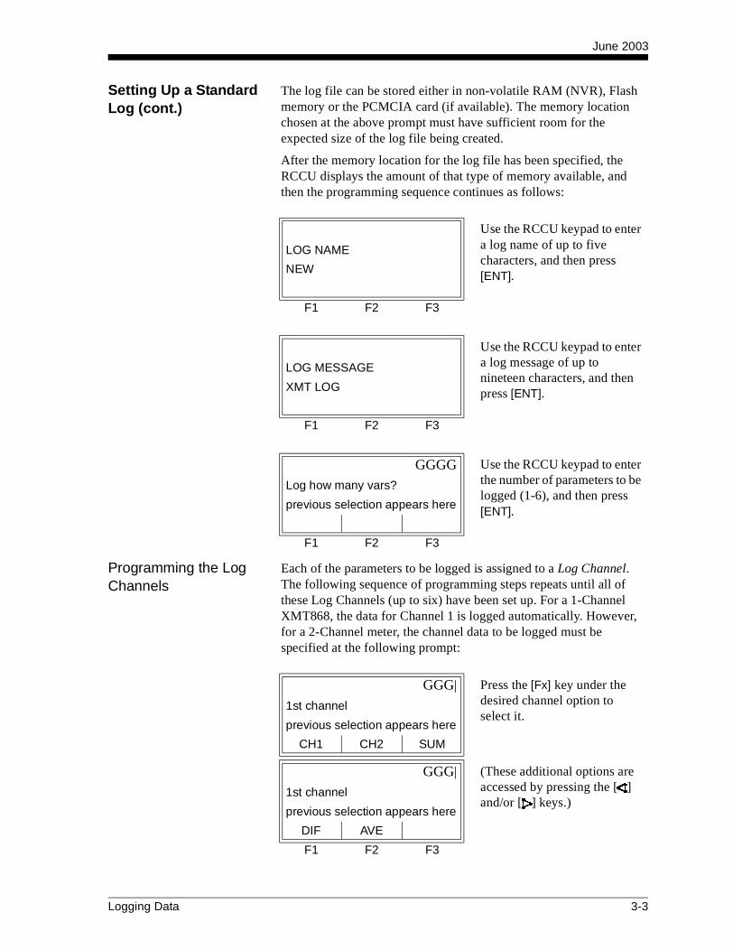
June 2003
Setting Up a Standard Log (cont.)
The log file can be stored either in non-volatile RAM (NVR), Flash memory or the PCMCIA card (if available). The memory location chosen at the above prompt must have sufficient room for the expected size of the log file being created.
After the memory location for the log file has been specified, the RCCU displays the amount of that type of memory available, and then the programming sequence continues as follows:
Programming the Log Channels
Each of the parameters to be logged is assigned to a Log Channel. The following sequence of programming steps repeats until all of these Log Channels (up to six) have been set up. For a 1-Channel XMT868, the data for Channel 1 is logged automatically. However, for a 2-Channel meter, the channel data to be logged must be specified at the following prompt:
Use the RCCU keypad to enter a log name of up to five characters, and then press [ENT].
LOG NAME
NEW
F1 F2 F3
Use the RCCU keypad to enter a log message of up to nineteen characters, and then press [ENT].
LOG MESSAGE
XMT LOG
F1 F2 F3
GGGG Use the RCCU keypad to enter the number of parameters to be logged (1-6), and then press [ENT].
Log how many vars?
previous selection appears here
F1 F2 F3
GGG| Press the [Fx] key under the desired channel option to select it.
1st channel
previous selection appears here
CH1 CH2 SUM
GGG| (These additional options are accessed by pressing the [ ] and/or [ ] keys.)
1st channel
previous selection appears here
DIF AVE
F1 F2 F3
Logging Data 3-3

June 2003
Programming the Log Channels (cont.)
See Table 3-1 below for a description of the channel options available at the previous prompt.
The flow parameter to be logged may now be selected as follows:
Note: The DIAG* option listed in the above prompt and in Table 3-2 on page 3-5 represents all of the individual diagnostic parameters that appear. See Chapter 3, Diagnostics, of the Service Manual for a complete description of these options.
Table 3-1: Channel Options
Option DescriptionCH1 Channel 1
CH2 Channel 2SUM CH1+CH2
DIF CH1-CH2AVE (CH1+CH2)/2
GGG| Use the [ ] and [ ] keys to find the desired flow parameter, and press the [Fx] key under it to select it.
Measurement Name 1
previous selection appears here
VEL VOLUM +TOTL
GGG| (See Table 3-2 on page 3-5 for a description of the available measurement parameters.)
Measurement Name 1
previous selection appears here
-TOTL TIME MDOT
LIVE FLOW Link GGG|
previous selections appear here
current reading appears here
+MASS -MASS POWER
LIVE FLOW Link GGG|
previous selections appear here
current reading appears here
+ENRG -ENRG DIAG*
F1 F2 F3
3-4 Logging Data
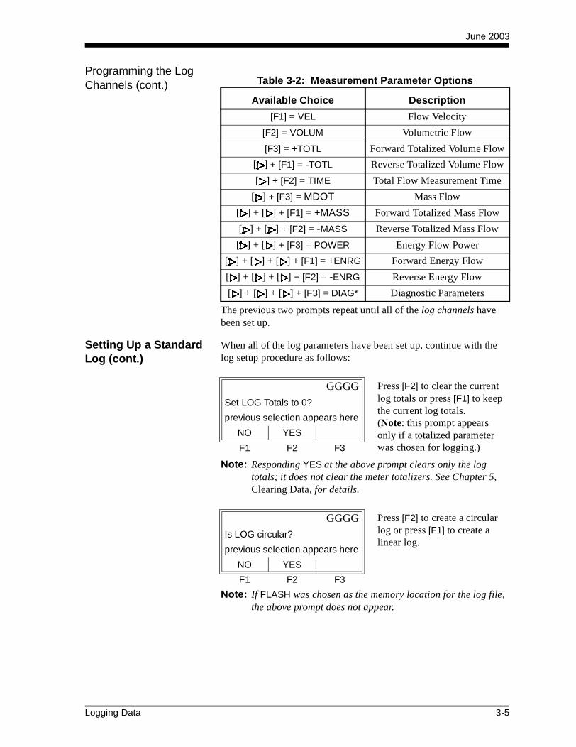
June 2003
Programming the Log Channels (cont.)
The previous two prompts repeat until all of the log channels have been set up.
Setting Up a Standard Log (cont.)
When all of the log parameters have been set up, continue with the log setup procedure as follows:
Note: Responding YES at the above prompt clears only the log totals; it does not clear the meter totalizers. See Chapter 5, Clearing Data, for details.
Note: If FLASH was chosen as the memory location for the log file, the above prompt does not appear.
Table 3-2: Measurement Parameter Options
Available Choice Description
[F1] = VEL Flow Velocity
[F2] = VOLUM Volumetric Flow
[F3] = +TOTL Forward Totalized Volume Flow
[ ] + [F1] = -TOTL Reverse Totalized Volume Flow
[ ] + [F2] = TIME Total Flow Measurement Time
[ ] + [F3] = MDOT Mass Flow
[ ] + [ ] + [F1] = +MASS Forward Totalized Mass Flow
[ ] + [ ] + [F2] = -MASS Reverse Totalized Mass Flow
[ ] + [ ] + [F3] = POWER Energy Flow Power
[ ] + [ ] + [ ] + [F1] = +ENRG Forward Energy Flow
[ ] + [ ] + [ ] + [F2] = -ENRG Reverse Energy Flow
[ ] + [ ] + [ ] + [F3] = DIAG* Diagnostic Parameters
GGGG Press [F2] to clear the current log totals or press [F1] to keep the current log totals. (Note: this prompt appears only if a totalized parameter was chosen for logging.)
Set LOG Totals to 0?
previous selection appears here
NO YES
F1 F2 F3
GGGG Press [F2] to create a circular log or press [F1] to create a linear log.
Is LOG circular?
previous selection appears here
NO YES
F1 F2 F3
Logging Data 3-5
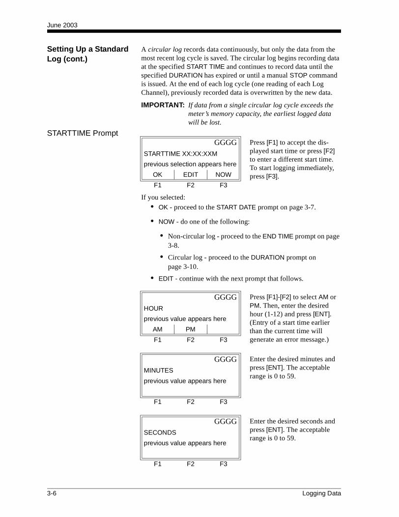
June 2003
Setting Up a Standard Log (cont.)
A circular log records data continuously, but only the data from the most recent log cycle is saved. The circular log begins recording data at the specified START TIME and continues to record data until the specified DURATION has expired or until a manual STOP command is issued. At the end of each log cycle (one reading of each Log Channel), previously recorded data is overwritten by the new data.
IMPORTANT: If data from a single circular log cycle exceeds the meter’s memory capacity, the earliest logged data will be lost.
STARTTIME Prompt
If you selected:
• OK - proceed to the START DATE prompt on page 3-7.
• NOW - do one of the following:
• Non-circular log - proceed to the END TIME prompt on page 3-8.
• Circular log - proceed to the DURATION prompt onpage 3-10.
• EDIT - continue with the next prompt that follows.
GGGG Press [F1] to accept the dis-played start time or press [F2] to enter a different start time. To start logging immediately, press [F3].
STARTTIME XX:XX:XXM
previous selection appears here
OK EDIT NOW
F1 F2 F3
GGGG Press [F1]-[F2] to select AM or PM. Then, enter the desired hour (1-12) and press [ENT]. (Entry of a start time earlier than the current time will generate an error message.)
HOUR
previous value appears here
AM PM
F1 F2 F3
GGGG Enter the desired minutes and press [ENT]. The acceptable range is 0 to 59.
MINUTES
previous value appears here
F1 F2 F3
GGGG Enter the desired seconds and press [ENT]. The acceptable range is 0 to 59.
SECONDS
previous value appears here
F1 F2 F3
3-6 Logging Data
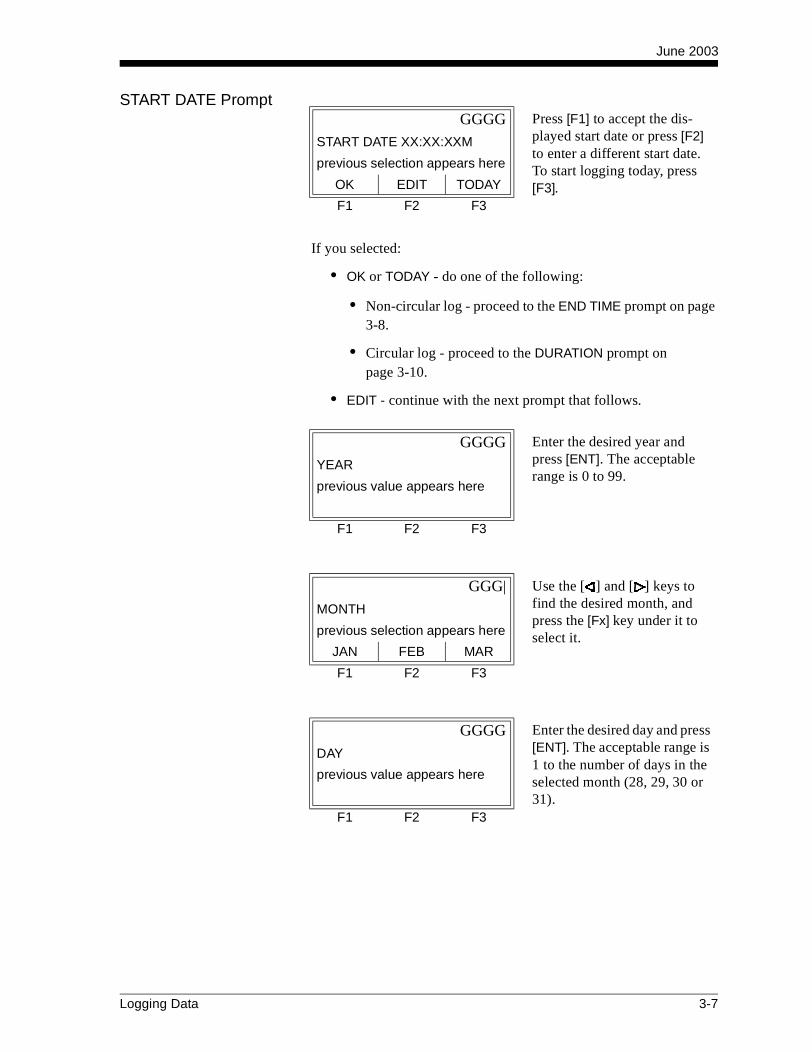
June 2003
START DATE Prompt
If you selected:
• OK or TODAY - do one of the following:
• Non-circular log - proceed to the END TIME prompt on page 3-8.
• Circular log - proceed to the DURATION prompt onpage 3-10.
• EDIT - continue with the next prompt that follows.
GGGG Press [F1] to accept the dis-played start date or press [F2] to enter a different start date. To start logging today, press [F3].
START DATE XX:XX:XXM
previous selection appears here
OK EDIT TODAY
F1 F2 F3
GGGG Enter the desired year and press [ENT]. The acceptable range is 0 to 99.
YEAR
previous value appears here
F1 F2 F3
GGG| Use the [ ] and [ ] keys to find the desired month, and press the [Fx] key under it to select it.
MONTH
previous selection appears here
JAN FEB MAR
F1 F2 F3
GGGG Enter the desired day and press [ENT]. The acceptable range is 1 to the number of days in the selected month (28, 29, 30 or 31).
DAY
previous value appears here
F1 F2 F3
Logging Data 3-7

June 2003
END TIME Prompt
If you selected:
• OK - proceed to the END DATE prompt on page 3-9.
• TIMED - proceed to the LOG TIME prompt on page 3-10.
• EDIT - continue with the next prompt that follows.
Note: The log END TIME must exceed the log START TIME by at least five minutes. Failure to observe this restriction will result in an error message.
GGGG Press [F1] to accept the displayed end time or press [F2] to enter a different end time. To select a specific time period for the log to run, press [F3].
END TIME XX:XX:XXM
previous selection appears here
OK EDIT TIMED
F1 F2 F3
GGGG Press [F1]-[F2] to select AM or PM. Then, enter the desired hour (1-12) and press [ENT].
HOUR
previous value appears here
AM PM
F1 F2 F3
GGGG Enter the desired minutes and press [ENT]. The acceptable range is 0 to 59.
MINUTES
previous value appears here
F1 F2 F3
GGGG Enter the desired seconds and press [ENT]. The acceptable range is 0 to 59.
SECONDS
previous value appears here
F1 F2 F3
3-8 Logging Data
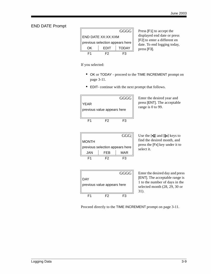
June 2003
END DATE Prompt
If you selected:
• OK or TODAY - proceed to the TIME INCREMENT prompt on page 3-11.
• EDIT- continue with the next prompt that follows.
Proceed directly to the TIME INCREMENT prompt on page 3-11.
GGGG Press [F1] to accept the displayed end date or press [F2] to enter a different en date. To end logging today, press [F3].
END DATE XX:XX:XXM
previous selection appears here
OK EDIT TODAY
F1 F2 F3
GGGG Enter the desired year and press [ENT]. The acceptable range is 0 to 99.
YEAR
previous value appears here
F1 F2 F3
GGG| Use the [ ] and [ ] keys to find the desired month, and press the [Fx] key under it to select it.
MONTH
previous selection appears here
JAN FEB MAR
F1 F2 F3
GGGG Enter the desired day and press [ENT]. The acceptable range is 1 to the number of days in the selected month (28, 29, 30 or 31).
DAY
previous value appears here
F1 F2 F3
Logging Data 3-9

June 2003
DURATION Prompt If a circular log was specified, the programming sequence continues here after the log start time and/or start date is entered.
Proceed directly to the TIME INCREMENT prompt on page 3-11.
LOG TIME Prompt If TIMED was selected at the END TIME prompt, the programming sequence continues here.
Proceed directly to the TIME INCREMENT prompt on page 3-11.
GGGG Press the [Fx] key under the desired units of measure. Then, key in the desired number of hours/days and press [ENT]. Proceed directly to the TIME INCREMENT prompt.
DURATION
previous value appears here
HOURS DAYS
F1 F2 F3
GGG| Use the [ ] and [ ] keys to find the desired logging dura-tion, and press the [Fx] key under it to select it.
LOG TIME
previous selection appears here
10min 30min 60min
GGG|
LOG TIME
previous selection appears here
3 HR 6 HR 12 HR
GGG|
LOG TIME
previous selection appears here
24 HR
F1 F2 F3
3-10 Logging Data

June 2003
TIME INCREMENT Prompt
Regardless of which of the various options were selected during the previous programming steps, all of the paths converge at this point.
The time increment is the frequency at which the Model XMT868 takes and records data measurements. If any reading takes longer than the programmed time increment, the log is filled in with the next consecutive reading. For example, assume that a velocity value of 3 ft/sec is recorded at 12:00:00 in a log with a time increment of five seconds. If the next reading is 8 ft/sec and it takes the meter 12 seconds to read this value, then both of the missed readings (12:00:05 and 12:00:10) will be filled in with the 8 ft/sec value.
Setting Up a Standard Log (cont.)
Now that the standard log setup has been completed, the following confirmation screen appears:
Note: Although each log is restricted to six logged parameters, it is still possible to log more than six parameters. Simply re-enter the STD sub-menu as many times as necessary to set up additional logs. Select the other desired parameters, and run these logs simultaneously with the first log.
GGG| Use the [ ] and [ ] keys to find the desired time increment, and press the [Fx] key under it to select it.
TIME INCREMENT
previous selection appears here
5sec 10sec 30sec
GGG|
TIME INCREMENT
previous selection appears here
1min 3min 6min
GGG|
TIME INCREMENT
previous selection appears here
12min 30min 60min
F1 F2 F3
GGGG Press [F1] or [ENT] to acknowledge the message and press [EXIT] to return to the main RCCU menu and begin logging.
log created
OK
OK
F1 F2 F3
Logging Data 3-11

June 2003
Setting Up an Error Log
An error log updates every 5 seconds (or whenever the display updates), but only if a new error condition occurs. Error logs have a fixed length of 2 pages and contain sixty records per page. Each record shows the time of the error, the measurement parameter values at that time, and the error code message. The logged values of the chosen measurement parameters at the time of the error condition provide valuable troubleshooting information.
If [ ] + [F1] was pressed to select ERROR at the LOGGING prompt shown on page 3-2, follow the instructions in this section:
The log file can be stored either in non-volatile RAM (NVR), Flash memory or the PCMCIA card (if available). The memory location chosen at the above prompt must have sufficient room for the expected size of the log file being created.
IMPORTANT: If a circular log is being set up, DO NOT choose FLASH as the memory location for the log file.
After the memory location for the log file has been specified, the RCCU displays the amount of that type of memory available, and then the programming sequence continues as follows:
GGGG Press the [Fx] key under the desired option to select it. (Note: the PCMCIA option only appears if such a card has been installed.)
LOG LOCATION
previous selection appears here
NVR FLASH PCMCIA
F1 F2 F3
Use the RCCU keypad to enter a log name of up to five characters, and then press [ENT].
LOG NAME
enter new name here
F1 F2 F3
Use the RCCU keypad to enter a log message of up to nineteen characters, and then press [ENT].
LOG MESSAGE
XMT LOG
F1 F2 F3
3-12 Logging Data

June 2003
Programming the Log Channels
Each of the parameters to be logged is assigned to a Log Channel. The following sequence of programming steps repeats until all of these Log Channels (up to six) have been set up.
For a 1-Channel XMT868, the data for Channel 1 is logged automatically. However, for a 2-Channel meter, the channel data to be logged must be specified at the following prompt:
See Table 3-3 below for a description of the channel options available at the above prompt.
GGGG Use the RCCU keypad to enter the number of parameters to be logged (1-6), and then press [ENT].
Log how many vars?
enter # of parameters here
F1 F2 F3
GGG| Press the [Fx] key under the desired channel option to select it.
1st channel
previous selection appears here
CH1 CH2 SUM
GGG| (These additional options are accessed by pressing the [ ] and/or [ ] keys.)
1st channel
previous selection appears here
DIF AVE
F1 F2 F3
Table 3-3: Channel Options
Option Description
CH1 Channel 1
CH2 Channel 2
SUM CH1+CH2
DIF CH1-CH2
AVE (CH1+CH2)/2
Logging Data 3-13
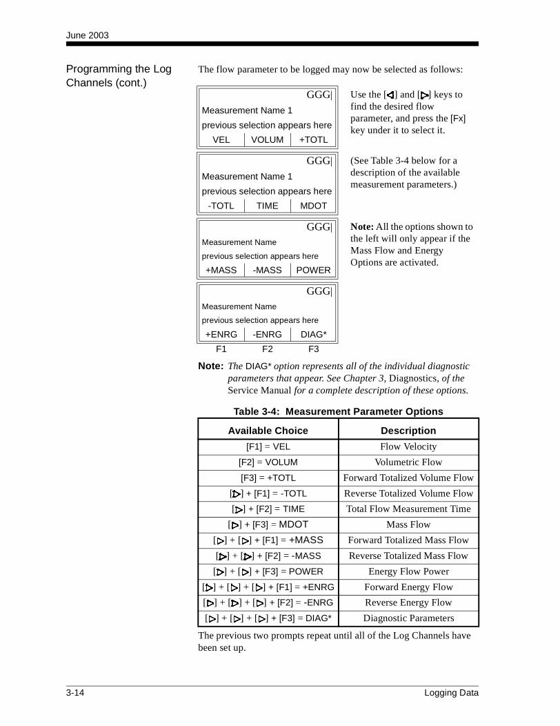
June 2003
Programming the Log Channels (cont.)
The flow parameter to be logged may now be selected as follows:
Note: The DIAG* option represents all of the individual diagnostic parameters that appear. See Chapter 3, Diagnostics, of the Service Manual for a complete description of these options.
The previous two prompts repeat until all of the Log Channels have been set up.
GGG| Use the [ ] and [ ] keys to find the desired flow parameter, and press the [Fx] key under it to select it.
Measurement Name 1
previous selection appears here
VEL VOLUM +TOTL
GGG| (See Table 3-4 below for a description of the available measurement parameters.)
Measurement Name 1
previous selection appears here
-TOTL TIME MDOT
GGG| Note: All the options shown to the left will only appear if the Mass Flow and Energy Options are activated.
Measurement Name
previous selection appears here
+MASS -MASS POWER
GGG|
Measurement Name
previous selection appears here
+ENRG -ENRG DIAG*
F1 F2 F3
Table 3-4: Measurement Parameter Options
Available Choice Description
[F1] = VEL Flow Velocity
[F2] = VOLUM Volumetric Flow
[F3] = +TOTL Forward Totalized Volume Flow
[ ] + [F1] = -TOTL Reverse Totalized Volume Flow
[ ] + [F2] = TIME Total Flow Measurement Time
[ ] + [F3] = MDOT Mass Flow
[ ] + [ ] + [F1] = +MASS Forward Totalized Mass Flow
[ ] + [ ] + [F2] = -MASS Reverse Totalized Mass Flow
[ ] + [ ] + [F3] = POWER Energy Flow Power
[ ] + [ ] + [ ] + [F1] = +ENRG Forward Energy Flow
[ ] + [ ] + [ ] + [F2] = -ENRG Reverse Energy Flow
[ ] + [ ] + [ ] + [F3] = DIAG* Diagnostic Parameters
3-14 Logging Data

June 2003
Setting Up an Error Log (cont.)
When all of the log parameters have been set up, continue with the log setup procedure as follows:
Note: Responding YES at the above prompt clears only the log totals; it does not clear the meter totalizers. See Chapter 5, Clearing Data, for details.
Note: If FLASH was chosen as the memory location for the log file, the above prompt does not appear.
A circular log records data continuously, but only the data from the most recent log cycle is saved. The circular log begins recording data at the specified START TIME and continues to record data until a manual STOP command is issued. At the end of each log cycle (one reading of each Log Channel), previously recorded data is overwritten by the new data.
IMPORTANT: If data from a single circular log cycle exceeds the meter’s memory capacity, the earliest logged data will be lost.
GGGG Press [F2] to clear the current log totals or press [F1] to keep the current log totals.(Note: this prompt appears only if a totalized parameter was chosen for logging.)
Set LOG Totals to 0?
previous selection appears here
NO YES
F1 F2 F3
GGGG Press [F2] to create a circular log or press [F1] to create a linear log.
Is LOG circular?
previous selection appears here
NO YES
F1 F2 F3
Logging Data 3-15

June 2003
STARTTIME Prompt
If you selected:
• OK - proceed to the START DATE prompt on page 3-17.
• NOW - proceed to LOG CREATED prompt on page 3-18.
• EDIT - continue with the next prompt that follows.
GGGG Press [F1] to accept the dis-played start time or press [F2] to enter a different start time. To start logging immediately, press [F3].
STARTTIME XX:XX:XXM
previous selection appears here
OK EDIT NOW
F1 F2 F3
GGGG Press [F1]-[F2] to select AM or PM. Then, enter the desired hour (1-12) and press [ENT]. (Entry of a start time earlier than the current time will generate an error message.)
HOUR
previous value appears here
AM PM
F1 F2 F3
GGGG Enter the desired minutes and press [ENT]. The acceptable range is 0 to 59.
MINUTES
previous value appears here
F1 F2 F3
GGGG Enter the desired seconds and press [ENT]. The acceptable range is 0 to 59.
SECONDS
previous value appears here
F1 F2 F3
3-16 Logging Data

June 2003
START DATE Prompt
If you selected:
• OK or TODAY - proceed to the LOG CREATED prompt on page 3-18.
• EDIT - continue with the next prompt that follows.
GGGG Press [F1] to accept the dis-played start date or press [F2] to enter a different start date. To start logging today, press [F3].
START DATE XX:XX:XXM
previous selection appears here
OK EDIT TODAY
F1 F2 F3
GGGG Enter the desired year and press [ENT]. The acceptable range is 0 to 99.
YEAR
previous value appears here
F1 F2 F3
GGG| Use the [ ] and [ ] keys to find the desired month, and press the [Fx] key under it to select it.
MONTH
previous selection appears here
JAN FEB MAR
F1 F2 F3
GGGG Enter the desired day and press [ENT]. The acceptable range is 1 to the number of days in the selected month (28, 29, 30 or 31).
DAY
previous value appears here
F1 F2 F3
Logging Data 3-17

June 2003
Setting Up an Error Log (cont.)
The error log will continue to run until it is manually stopped, the meter runs out of memory (for a non-circular log), or the entire 120 records (2 pages x 60 records/page) have been logged.
Now that the error log setup has been completed, the following confirmation screen appears:
Checking the XMT868 Memory
Use the MEM sub-menu to verify that the available log memory is sufficient for the desired log. If the expected amount of logged data will exceed the remaining memory capacity, the Model XMT868 suggests that some old logs be cleared to make room for the new log.
If [F2] was pressed to select MEM at the LOGGING prompt shown on page 3-2, the following message appears:
After displaying the above message, the meter returns to the initial LOGGING prompt shown on page 3-2.
GGGG Press [F1] or [ENT] to acknowledge the message and return to the main RCCU menu and begin logging.
log created
OK
OK
F1 F2 F3
Requested function This function has not yet been implemented for the XMT868.cannot be executed
Returning to last
instruction.
F1 F2 F3
3-18 Logging Data

June 2003
Stopping a Log Use the STOP sub-menu to terminate a logging process that is currently active. If [F3] was pressed to select STOP at the LOGGING prompt shown on page 3-2, complete the following steps to stop a log:
Note: Once a log is stopped it cannot be restarted, but the log remains in memory. To clear the log from memory, refer to Chapter 5, Clearing Data, for instructions.
Uploading a Log File to the RCCU
Any completed log files stored in the XMT868’s memory may be uploaded into the RCCU’s memory. The files may then be displayed and examined on the RCCU display without the need to establish an ONLINE communication link with the XMT868.
To upload a log file, power up the RCCU and complete the following steps:
GGG| Use the [ ] and [ ] keys to find the desired log, and press the [Fx] key under it to select it.
Log Name
previous selection appears here
LOG1 LOG2 LOG3
GGG| (This prompt displays all active and completed log files currently stored in memory.)
Log Name
previous selection appears here
LOG4 LOG5
F1 F2 F3
GGGG Press [F1] to continue logging or press [F2] to stop logging. The meter returns to the LOGGING prompt shown on page 3-2.
Stop Logging?
previous selection appears here
NO YES
F1 F2 F3
IDM MENU START GGGG Press the [F2] key to select ONLINE.IDM MENU
previous selection appears here
SYSTEM ONLINE OFFLNE
F1 F2 F3
Logging Data 3-19

June 2003
Uploading a Log File to the RCCU (cont.)
After communication between the RCCU and the XMT868 has been established (see Chapter 3, Operation, of the Startup Guide), refer to Figure A-7 on page A-7 and continue as follows:
ONLINE PROGRAM GGG| Press the [F2] key to select LOG.On Line Operations
previous selection appears here
PROG LOG DATA
ONLINE PROGRAM GGG| (These additional options are accessed by pressing the [ ] and/or [ ] keys.)
On Line Operations
previous selection appears here
SITE CLEAR TEST
F1 F2 F3
ONLINE PROGRAM GGG| Use the [ ] and [ ] keys to find the desired log file, and press the [Fx] key under it to select it.
LOG NAMES
previous selection appears here
LOG1 LOG2 LOG3
ONLINE PROGRAM GGG| (This prompt displays all completed log files currently stored in the XMT868’s memory.)
LOG NAMES
previous selection appears here
LOG4 LOG5
F1 F2 F3
3-20 Logging Data
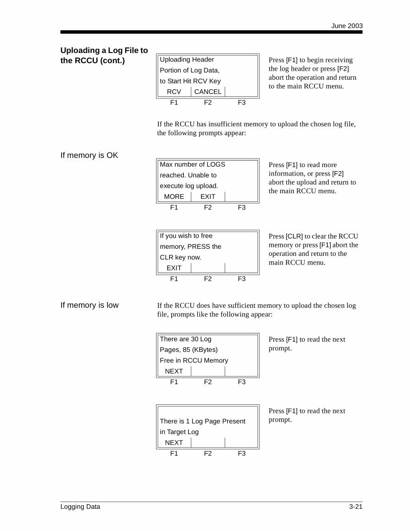
June 2003
Uploading a Log File to the RCCU (cont.)
If the RCCU has insufficient memory to upload the chosen log file, the following prompts appear:
If memory is OK
If memory is low If the RCCU does have sufficient memory to upload the chosen log file, prompts like the following appear:
Uploading Header Press [F1] to begin receiving the log header or press [F2] abort the operation and return to the main RCCU menu.
Portion of Log Data,
to Start Hit RCV Key
RCV CANCEL
F1 F2 F3
Max number of LOGS Press [F1] to read more information, or press [F2] abort the upload and return to the main RCCU menu.
reached. Unable to
execute log upload.
MORE EXIT
F1 F2 F3
If you wish to free Press [CLR] to clear the RCCU memory or press [F1] abort the operation and return to the main RCCU menu.
memory, PRESS the
CLR key now.
EXIT
F1 F2 F3
There are 30 Log Press [F1] to read the next prompt.Pages, 85 (KBytes)
Free in RCCU Memory
NEXT
F1 F2 F3
Press [F1] to read the next prompt.There is 1 Log Page Present
in Target Log
NEXT
F1 F2 F3
Logging Data 3-21
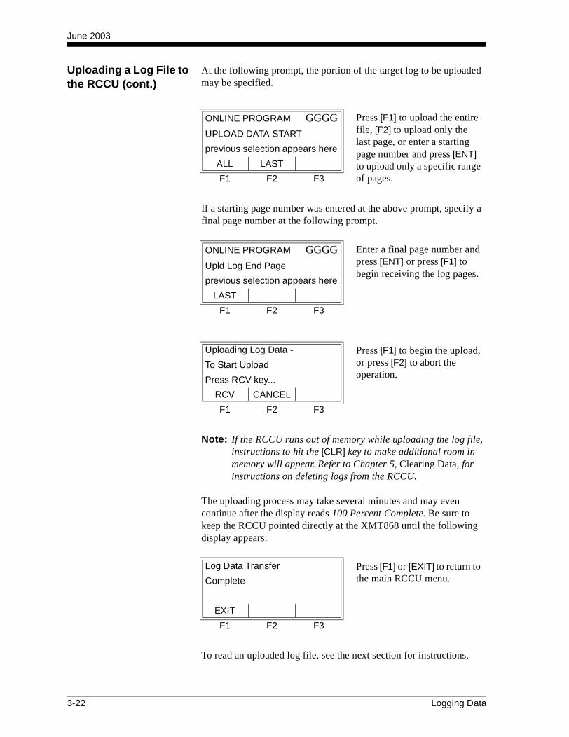
June 2003
Uploading a Log File to the RCCU (cont.)
At the following prompt, the portion of the target log to be uploaded may be specified.
If a starting page number was entered at the above prompt, specify a final page number at the following prompt.
Note: If the RCCU runs out of memory while uploading the log file, instructions to hit the [CLR] key to make additional room in memory will appear. Refer to Chapter 5, Clearing Data, for instructions on deleting logs from the RCCU.
The uploading process may take several minutes and may even continue after the display reads 100 Percent Complete. Be sure to keep the RCCU pointed directly at the XMT868 until the following display appears:
To read an uploaded log file, see the next section for instructions.
ONLINE PROGRAM GGGG Press [F1] to upload the entire file, [F2] to upload only the last page, or enter a starting page number and press [ENT] to upload only a specific range of pages.
UPLOAD DATA START
previous selection appears here
ALL LAST
F1 F2 F3
ONLINE PROGRAM GGGG Enter a final page number and press [ENT] or press [F1] to begin receiving the log pages.
Upld Log End Page
previous selection appears here
LAST
F1 F2 F3
Uploading Log Data - Press [F1] to begin the upload, or press [F2] to abort the operation.
To Start Upload
Press RCV key...
RCV CANCEL
F1 F2 F3
Log Data Transfer Press [F1] or [EXIT] to return to the main RCCU menu.Complete
EXIT
F1 F2 F3
3-22 Logging Data

June 2003
Reading a Log File with the RCCU
Any log file that has been uploaded into the RCCU’s memory may be read on the RCCU’s display. However, because the display is too small to show an entire page or record at once, the log must be shown one screen at a time.
Log File Structure To understand how the log is divided into screens, the structure of a log file must first be discussed. A typical XMT868 log file consists of pages and records, with a maximum of 120 records per page and a maximum number of pages limited by the amount of memory available in the XMT868. Each page is further sub-divided as follows:
Header Record - this is listed as Record #0 and it includes:
• log name
• log start date and start time
• log end date and end time
• information about each of the parameters selected for logging
Data Records - these are listed as Record #1 to Record #x (where,x = number of final record or 120 max.). Each data record includes:
• date and time of the record
• values for all logged parameters at that time
• any error codes generated at that time
Figure 3-1 below shows the screens of a typical 3-parameter log file. Note that the first column shows the date and time of the record and that there is one additional column for each logged parameter. Each row represents one record.
Figure 3-1: A Typical Log File
<SCRN SCRN> START
10:43:57A
14 MAY 96
LOG1 P#1 R#0
14 MAY 96
11:40:53A
LOG1 P#1 R#1
14 MAY 96
10:43:57A
<SCRN
11:40:53A
14 MAY 96
SCRN> START
11:40:53A10:43:57A
<SCRN SCRN> START
14 MAY 96
LOG1 P#1 R#2
14 MAY 96
LOG1 P#1 R#2
<SCRN
<SCRN
SCRN>
SCRN>
START
START
LOG1 P#1 R#1
LOG1 P#1 R#0
CH1 SS up
<SCRN
Veloc. Ra
CH1 E3
SCRN> START
<SCRN
<SCRN
SCRN>
SCRN>
START
START
LOG1 P#1 R#0
<SCRN SCRN> START
<SCRN
<SCRN
SCRN>
SCRN> START
START
<SCRN
LOG1 P#1 R#0
SCRN> START
CH1 E3CH1 SS up
CH1 SS up CH1 E3
53.7 Veloc. Ra
53.7 Veloc. Ra
LOG1 P#1 R#1
LOG1 P#1 R#2
Veloc. Ra
CH1 E3CH1 SS do
53.7
CH1 E3
Veloc. Ra
53.7
CH1 E3
Veloc. Ra
CH1 SS do
CH1 SS do
LOG1 P#1 R#1
LOG1 P#1 R#2
CH1 Tup CH1 E3
Veloc. Ra
180.1
CH1 E3
Veloc. Ra
180.1
CH1 E3
Veloc. Ra
usec
CH1 Tup
CH1 Tup
Date and TimeScreens Data Screens
HeaderRecord
DataRecords
Logging Data 3-23

June 2003
Log File Structure (cont.) As shown in Figure 3-1 on page 3-23 there are four different categories of screens in the log file:
• header record - date and time screen (row 1, column 1)
• header record - data screens (row 1, columns 2-4)
• data record - date and time screens (rows 2-end, column 1)
• data record - data screens (rows 2-end, columns 2-4)
See Figure 3-2 below for a complete description of the information contained in each of these screen types.
Figure 3-2: RCCU Log Display Screens
<SCRN SCRN> START
10:43:57A
14 MAY 96
LOG1 P#1 R#0
14 MAY 96
11:40:53A
11:40:53A10:43:57A
<SCRN SCRN> START
14 MAY 96
LOG1 P#1 R#2
14 MAY 96
<SCRN SCRN> START
<SCRN
LOG1 P#1 R#0
SCRN> START
LOG1 P#1 R#2
CH1 Tup CH1 E3
Veloc. Ra
180.1
CH1 E3
Veloc. Ra
usec
CH1 Tup
Record Number
Indicator Block
Log End Date
Log End Time
Page Number
Log Name
Log Start Date
Log Start Time
Header RecordTime and Date Screen
Record Number
Error Description
Error Code
Indicator BlockData Screen
Units
Channel Option
Header Record Log Name
Page Number
Record Number
Log End Time
Log End Date
Indicator BlockTime and Date Screen
Reading Time
Reading Date
Data Record Log Name
Page Number
Record Number
Error Description
Error Code
Indicator BlockData Screen
Value
Channel Option
Data Record Log Name
Page Number
Parameter
Parameter
3-24 Logging Data
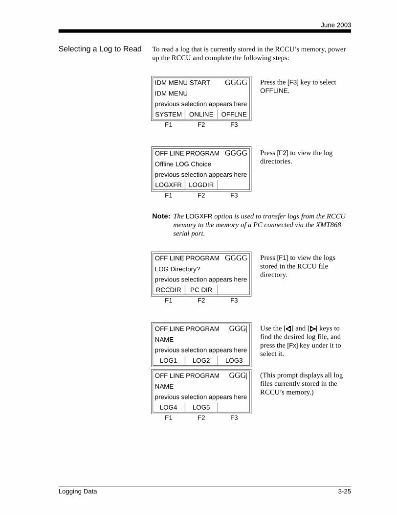
June 2003
Selecting a Log to Read To read a log that is currently stored in the RCCU’s memory, power up the RCCU and complete the following steps:
Note: The LOGXFR option is used to transfer logs from the RCCU memory to the memory of a PC connected via the XMT868 serial port.
IDM MENU START GGGG Press the [F3] key to select OFFLINE.IDM MENU
previous selection appears here
SYSTEM ONLINE OFFLNE
F1 F2 F3
OFF LINE PROGRAM GGGG Press [F2] to view the log directories.Offline LOG Choice
previous selection appears here
LOGXFR LOGDIR
F1 F2 F3
OFF LINE PROGRAM GGGG Press [F1] to view the logs stored in the RCCU file directory.
LOG Directory?
previous selection appears here
RCCDIR PC DIR
F1 F2 F3
OFF LINE PROGRAM GGG| Use the [ ] and [ ] keys to find the desired log file, and press the [Fx] key under it to select it.
NAME
previous selection appears here
LOG1 LOG2 LOG3
OFF LINE PROGRAM GGG| (This prompt displays all log files currently stored in the RCCU’s memory.)
NAME
previous selection appears here
LOG4 LOG5
F1 F2 F3
Logging Data 3-25
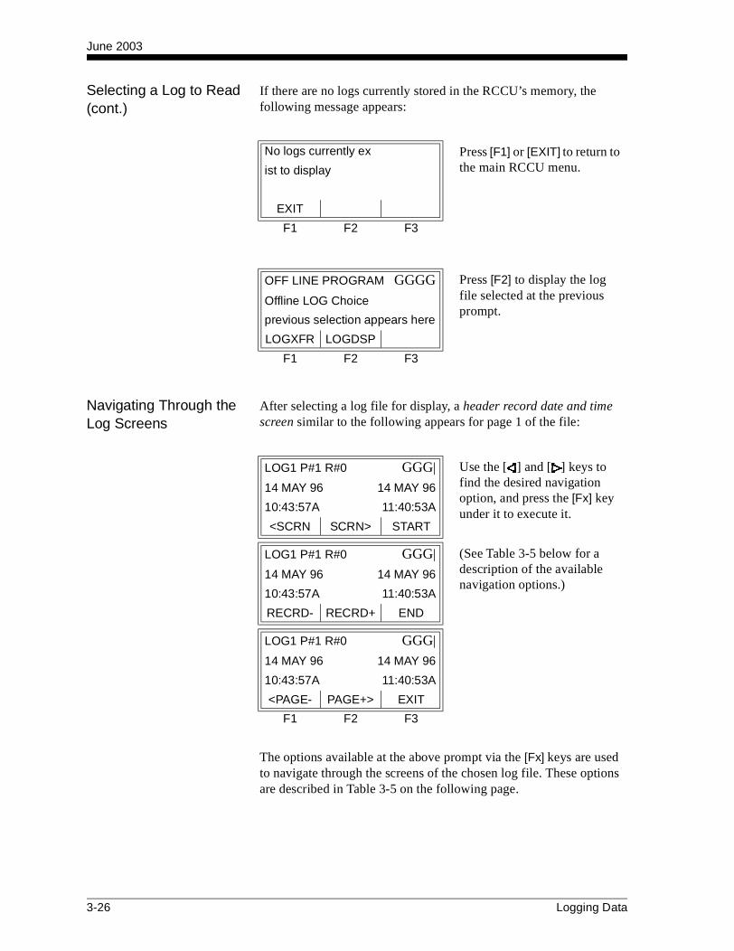
June 2003
Selecting a Log to Read (cont.)
If there are no logs currently stored in the RCCU’s memory, the following message appears:
Navigating Through the Log Screens
After selecting a log file for display, a header record date and time screen similar to the following appears for page 1 of the file:
The options available at the above prompt via the [Fx] keys are used to navigate through the screens of the chosen log file. These options are described in Table 3-5 on the following page.
No logs currently ex Press [F1] or [EXIT] to return to the main RCCU menu.ist to display
EXIT
F1 F2 F3
OFF LINE PROGRAM GGGG Press [F2] to display the log file selected at the previous prompt.
Offline LOG Choice
previous selection appears here
LOGXFR LOGDSP
F1 F2 F3
LOG1 P#1 R#0 GGG| Use the [ ] and [ ] keys to find the desired navigation option, and press the [Fx] key under it to execute it.
14 MAY 96 14 MAY 96
10:43:57A 11:40:53A
<SCRN SCRN> START
LOG1 P#1 R#0 GGG| (See Table 3-5 below for a description of the available navigation options.)
14 MAY 96 14 MAY 96
10:43:57A 11:40:53A
RECRD- RECRD+ END
LOG1 P#1 R#0 GGG|
14 MAY 96 14 MAY 96
10:43:57A 11:40:53A
<PAGE- PAGE+> EXIT
F1 F2 F3
3-26 Logging Data

June 2003
Navigating Through the Log Screens (cont.)
Note: The [↑ ] and [↓ ] keys on the RCCU keypad perform the same function as the RECRD- and RECRD+ options above. Also, the [EXIT] key on the keypad is equivalent to the EXIT option.
Table 3-5: Log Navigation Options
Option Name Description
<SCRN display the next screen to the left
SCRN> display the next screen to the right
START display the first record on the page
RECRD- display the next screen above
RECRD+ display the next screen below
END display the last record on the page
<PAGE- display the previous page
PAGE+> display the next page
EXIT return to the main menu
Logging Data 3-27

Chapter 4

Printing Data
Data Types for Printing . . . . . . . . . . . . . . . . . . . . . . . . . . . . . . . . . .4-1

June 2003
Data Types for Printing The Model XMT868 flowmeter has no ability to print any of its data either directly or through a Remote Control Communications Unit (RCCU). However, any of the data stored in its memory may be printed via the built-in RS232 communications port, using a computer terminal. In order to use the capability, the XMT868 must be linked to the computer terminal with the optional Instrument Data Manager (IDM) software.
Note: See Chapter 1, Installation, of the Startup Guide for instructions on wiring the RS232 serial port. For additional information, refer to EIA-RS Serial Communications Manual (916-054).
After making the hardware connections and installing the IDM software, the following data may be output to a printer connected to the personal computer:
• live data in numeric or graphical format
• log file in numeric or graphical format
• site file in tabular format
• transducer signal array data in tabular format
For detailed instructions on printing any of the data types listed above, consult the User’s Manual for the IDM software.
Printing Data 4-1

Chapter 5
Clearing Data
Introduction . . . . . . . . . . . . . . . . . . . . . . . . . . . . . . . . . . . . . . . . . . .5-1
Clearing the RCCU’s Memory . . . . . . . . . . . . . . . . . . . . . . . . . . . . .5-1
Clearing the XMT868’s Memory . . . . . . . . . . . . . . . . . . . . . . . . . . .5-4

June 2003
Introduction This chapter explains how to purge totalized measurements, site data and/or log files from both the XMT868’s memory and the RCCU’s memory. The instructions in this chapter are separated into the following two categories:
• Clearing the RCCU’s memory
• Clearing the XMT868’s memory
Note: For detailed information on creating a log file, see Chapter 3, Logging Data. For detailed information on programming site data, see Chapter 1, Programming Site Data.
Refer to Figure A-7 on page A-7 in Appendix A, Menu Maps, and proceed to the desired section for detailed instructions. Each sub-menu may be followed in the sequence shown or the [↑] and [↓] keys may be used to scroll through the prompts.
IMPORTANT: None of the clearing procedures described in this chapter can be undone. Be very sure that the exact consequences of a selected option are thoroughly understood before proceeding.
Clearing the RCCU’s Memory
If the RCCU’s available memory becomes nearly full, it may be necessary to purge some or all of the existing data from memory, before any additional data can be stored. In order to accomplish this task, press the [CLR] key on the RCCU keypad. Refer to Figure A-7 on page A-7 in Appendix A, Menu Maps.
IMPORTANT: If the RCCU is currently ONLINE, the [CLR] key will not be functional.
Based on the selection made at the above prompt, proceed to the appropriate sub-section for step-by-step instructions.
CLEAR START GGGG Press [F1] to clear a site file or press [F2] to clear a log file from the RCCU memory.
CLEAR
previous selection appears here
SITE LOG
F1 F2 F3
Clearing Data 5-1

June 2003
Clearing a Site File To clear a site file from the RCCU’s memory, complete the following steps:
Note: All site files currently stored in the RCCU’s memory appear at the next prompt. If there are no site files currently in memory, skip directly to the final prompt in this section.
Note: If [F1] = MORE is chosen above and there are no additional site files stored in the RCCU’s memory, the following prompt appears.
To clear additional data, proceed to the appropriate section of this chapter for instructions.
CLEAR SITE GGG| Use the [ ] and [ ] keys to access the files shown, and press the [Fx] key under the desired site file to delete it.
NAME
previous selection appears here
SITE1 SITE2 SITE3
CLEAR SITE GGG|
NAME
previous selection appears here
SITE4
F1 F2 F3
CLEAR SITE GGGG Press [F2] to clear the site file selected at the previous prompt, or press [F1] to abort the operation.
CLEAR NAME
previous selection appears here
NO YES
F1 F2 F3
Another selction? Press [F1] to return to the NAME prompt above and clear additional site files, or press [F2] to return to the main RCCU menu.
Press EXIT if done,
MORE to clear more
MORE EXIT
F1 F2 F3
CLEAR SITE GGGG Press any key to return to the main RCCU menu.All Sites Cleared!
hit key
F1 F2 F3
5-2 Clearing Data
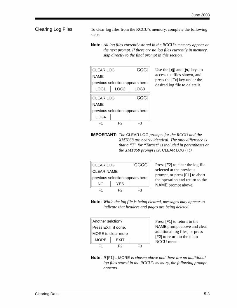
June 2003
Clearing Log Files To clear log files from the RCCU’s memory, complete the following steps:
Note: All log files currently stored in the RCCU’s memory appear at the next prompt. If there are no log files currently in memory, skip directly to the final prompt in this section.
IMPORTANT: The CLEAR LOG prompts for the RCCU and the XMT868 are nearly identical. The only difference is that a “T” for “Target” is included in parentheses at the XMT868 prompt (i.e. CLEAR LOG (T)).
Note: While the log file is being cleared, messages may appear to indicate that headers and pages are being deleted.
Note: If [F1] = MORE is chosen above and there are no additional log files stored in the RCCU’s memory, the following prompt appears.
CLEAR LOG GGG| Use the [ ] and [ ] keys to access the files shown, and press the [Fx] key under the desired log file to delete it.
NAME
previous selection appears here
LOG1 LOG2 LOG3
CLEAR LOG GGG|
NAME
previous selection appears here
LOG4
F1 F2 F3
CLEAR LOG GGGG Press [F2] to clear the log file selected at the previous prompt, or press [F1] to abort the operation and return to the NAME prompt above.
CLEAR NAME
previous selection appears here
NO YES
F1 F2 F3
Another selction? Press [F1] to return to the NAME prompt above and clear additional log files, or press [F2] to return to the main RCCU menu.
Press EXIT if done,
MORE to clear more
MORE EXIT
F1 F2 F3
Clearing Data 5-3

June 2003
Clearing Log Files (cont.)
To clear additional data, proceed to the appropriate section of this chapter for instructions.
Clearing the XMT868’s Memory
If the XMT868’s available memory becomes nearly full, it may be necessary to purge some or all of the existing data from memory, before any additional data can be stored. In order to accomplish this task, enter the Clear Menu as follows (refer to Figure A-7 on page A-7 in Appendix A, Menu Maps):
Note: Depending on the current configuration of the XMT868, it may be possible to add additional memory by installing an option card in Slot 2. See Chapter 4, Parts Replacement, of the Service Manual for details.
Based on the selection made at the above prompt, proceed to the appropriate section for step-by-step instructions.
CLEAR LOG GGGG Press any key to return to the main RCCU menu.All Logs Cleared!
hit key
F1 F2 F3
ONLINE PROGRAM GGG| Use the [ ] and [ ] keys to access the options shown, and press the [F2] key under CLEAR to access that menu.
On Line Operations
Edit Site
PROG LOG DATA
ONLINE PROGRAM GGG|
On Line Operations
Edit Site
SITE CLEAR TEST
F1 F2 F3
CLEAR START GGGG Press [F1] to clear a site file, press [F2] to clear a log file, or press [F3] to clear the totalizer.
Target CLEAR
previous selection appears here
SITE LOG TOTALS
F1 F2 F3
5-4 Clearing Data
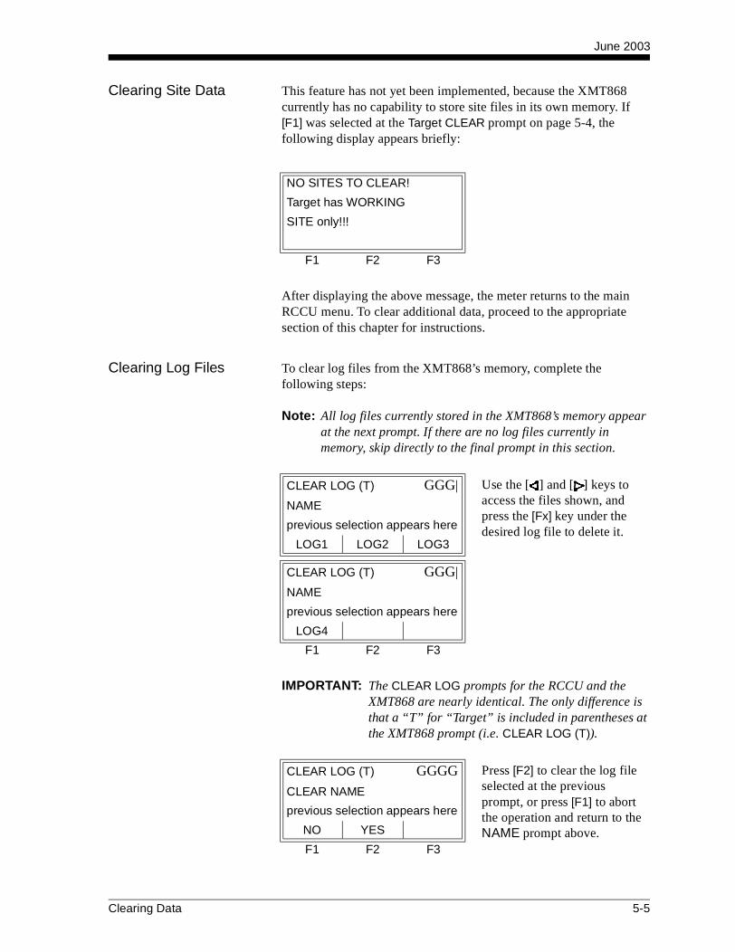
June 2003
Clearing Site Data This feature has not yet been implemented, because the XMT868 currently has no capability to store site files in its own memory. If [F1] was selected at the Target CLEAR prompt on page 5-4, the following display appears briefly:
After displaying the above message, the meter returns to the main RCCU menu. To clear additional data, proceed to the appropriate section of this chapter for instructions.
Clearing Log Files To clear log files from the XMT868’s memory, complete the following steps:
Note: All log files currently stored in the XMT868’s memory appear at the next prompt. If there are no log files currently in memory, skip directly to the final prompt in this section.
IMPORTANT: The CLEAR LOG prompts for the RCCU and the XMT868 are nearly identical. The only difference is that a “T” for “Target” is included in parentheses at the XMT868 prompt (i.e. CLEAR LOG (T)).
NO SITES TO CLEAR!
Target has WORKING
SITE only!!!
F1 F2 F3
CLEAR LOG (T) GGG| Use the [ ] and [ ] keys to access the files shown, and press the [Fx] key under the desired log file to delete it.
NAME
previous selection appears here
LOG1 LOG2 LOG3
CLEAR LOG (T) GGG|
NAME
previous selection appears here
LOG4
F1 F2 F3
CLEAR LOG (T) GGGG Press [F2] to clear the log file selected at the previous prompt, or press [F1] to abort the operation and return to the NAME prompt above.
CLEAR NAME
previous selection appears here
NO YES
F1 F2 F3
Clearing Data 5-5
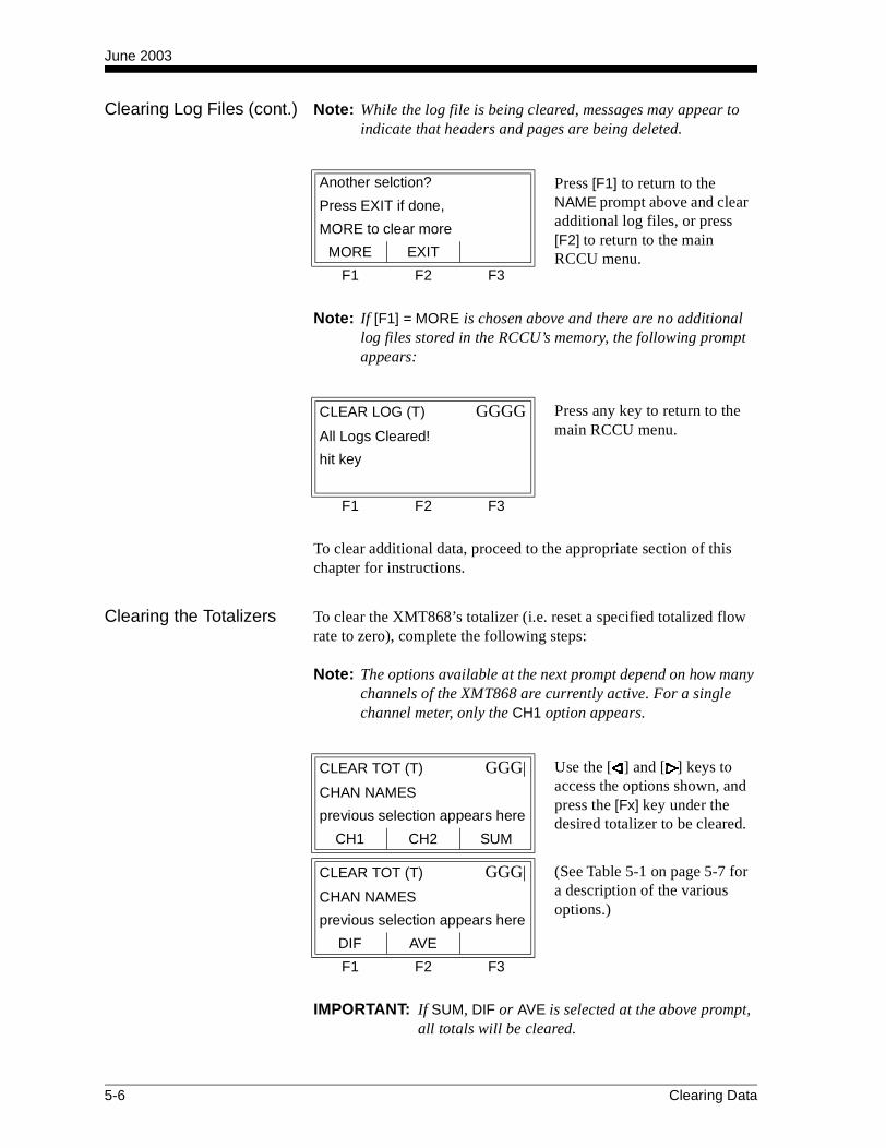
June 2003
Clearing Log Files (cont.) Note: While the log file is being cleared, messages may appear to indicate that headers and pages are being deleted.
Note: If [F1] = MORE is chosen above and there are no additional log files stored in the RCCU’s memory, the following prompt appears:
To clear additional data, proceed to the appropriate section of this chapter for instructions.
Clearing the Totalizers To clear the XMT868’s totalizer (i.e. reset a specified totalized flow rate to zero), complete the following steps:
Note: The options available at the next prompt depend on how many channels of the XMT868 are currently active. For a single channel meter, only the CH1 option appears.
IMPORTANT: If SUM, DIF or AVE is selected at the above prompt, all totals will be cleared.
Another selction? Press [F1] to return to the NAME prompt above and clear additional log files, or press [F2] to return to the main RCCU menu.
Press EXIT if done,
MORE to clear more
MORE EXIT
F1 F2 F3
CLEAR LOG (T) GGGG Press any key to return to the main RCCU menu.All Logs Cleared!
hit key
F1 F2 F3
CLEAR TOT (T) GGG| Use the [ ] and [ ] keys to access the options shown, and press the [Fx] key under the desired totalizer to be cleared.
CHAN NAMES
previous selection appears here
CH1 CH2 SUM
CLEAR TOT (T) GGG| (See Table 5-1 on page 5-7 for a description of the various options.)
CHAN NAMES
previous selection appears here
DIF AVE
F1 F2 F3
5-6 Clearing Data

June 2003
Clearing the Totalizers (cont.)
After the selected totalizer has been cleared, a confirmation message such as the following is displayed briefly:
After [EXIT] is selected at the above prompt, the RCCU terminates its link with the XMT868 and returns to its main menu. To clear additional data, proceed to the appropriate section of this chapter for instructions.
Table 5-1: Channel OptionsOption Description
CH1 Channel 1
CH2 Channel 2
SUM CH1+CH2
DIF CH1-CH2
AVE (CH1+CH2)/2
CLEAR TOT (T) GGGG Press [F2] to clear the totalizer selected at the previous prompt, or press [F1] to abort the operation.
CLEAR NAME
previous selection appears here
NO YES
F1 F2 F3
CLEAR TOT (T) GGGGTarget System’s
Totals for [CHAN NAME]
have been Deleted!
F1 F2 F3
Another selction? Press [F1] to return to the CHAN NAMES prompt on page 5-6 and clear additional totals, or press [F2] to leave the CLEAR menu.
Press EXIT if done,
MORE to clear more
MORE EXIT
F1 F2 F3
Clearing Data 5-7

Appendix A

Menu Maps
The CHx-ACTIV, SYSTM and PIPE with Energy OFF Menus . . . A-1
The CHx-ACTIV, SYSTM and PIPE with Energy ON Menus . . . . A-2
The CHx-I/O and SETUP Menus . . . . . . . . . . . . . . . . . . . . . . . . . . A-3
The Display, GLOBL-SYSTM, SLOT0 and COMM Menus . . . . . . A-4
The GLOBL-I/O-ERROR and OPTN Menus . . . . . . . . . . . . . . . . . A-5
The PROG-LOG Menu . . . . . . . . . . . . . . . . . . . . . . . . . . . . . . . . . . A-6
The LOG and CLEAR Menus. . . . . . . . . . . . . . . . . . . . . . . . . . . . . A-7

June 2003
A-1
Fig
ure
A-1
: T
he
CH
x-A
CT
IV, S
YS
TM
an
d P
IPE
wit
h E
ner
gy
OF
F M
enu
Map
sSETUPF2
z1
F1
I/O COMMSYSTM
F 1
I/OF2 F3
PAUSEPROG CALF1 F2
LOGF 3 F1*
SITE EDIT M ENU
[*only if data logging option card insta lled]
F2*
FILE
F3
TC2
OTHER
N1
POLYPF3
POLYEF2
C1 F2
ACRYL
PIPE SOU ND SPEED
1
ER
FLUID T YPE
WATER OILF1 F2 F1
ETHMETHF3
LN2F 2
OTHERF1
FREONF3
LUBENORMLF1
SEAF2
CRUDEF3 F1
F LU ID SOUN DSPEEDWAT ER TEMPER ATUR E
NOF 2F1
YES
[TR NFL]
See Figure A-3
W260W100F1
FLUID T YPE
OILF 2 F3 F1
OTHERM INIM UM SOUND SPEED
MAXIMU M SOU NDSPEED
F 2
STATC
ACTIVF2F 1
F1
TABLE
OFF
REYN OLD S C ORR ECTION
KV IN PU T SELEC TION
KIN EM ATIC VISCOSITY
CALIBRATION FACTOR
[W etted T rans ducers ][Clam p-On Transducers]
[TR NF L][TR ANS]
DEPTH OF REFLECT OR
F 2
52(V)1(Z)F1
3F 2 F3 F1
4
NU MBER OF T RAVERSES
TRAN SDUC ER SPACING
TRAC KIN G WIN DOW S?
See F igure A-3 See Figure A-4
[T RANS]
Menu Maps
PIPEF 2 F3
OFFF1
ONF2
F3
GAL/HF1
MGD ft3/sF 2
ft3/mF3
GAL/SF1
GAL/MF2
F2
SPEC
2MHz1MHz500kF1 F2 F3
5MHF
inchF 1
in/PI ft/PIfeetF2 F3 F 1
feetinchF1 F2
F1
inchF 2
feet
ENERGY OPTION
VOLU M ET RIC U NITS
TRAN SDUC ER N UM BER
SPECIAL TRAN SDUC ER
PIPE OD
PIPE W ALL
PAT H LEN GTH P
AXIAL LENGT H L
NOTE: Plain text represents prompt area messages andboxed text represents option bar choices.Fx represent function keys to select option bar choices.
CH AN NEL LABELChannel/Site status
F 2*F1*
TRANSOFF
ACTIVF 1
F2*F 1 F2 or F3
GLOBLCH1 CH2
SITE/CHAN NEL MESSAGE
10F1 F2
32F3 F 1
VOL D EC IMAL DIGITS
Channel PROGR AM
OFFLNESYSTEM
F1
ONLINE
F2 F 3
CLEARPROGF 1
PROG CH OICES
F2
LOGF3
DATA SITEF1 F2 F 3
TEST
R CCU Program
PROGR AM[*for 2-Channel meter only]
STDF 1
TRNFLF3*
SYSTM
Mft3/dF1
ft3/h BBL/HBBL/SF2 F3 F1
BBL/M MBL/DF 2 F3
A-I/MF1
A-I/S A-F/SF1F3F2
A-I/H A-I/DF3F 2
A-F/M
A-F/DA-F/HF1 F2
RAYLF1
SHEARF 2 F3
WETTD
W EDGE TYPE
F REQUEN CY
PIPE M AT ERIAL
IRONF1
STEEL CuF2 F 3 F2
BRASSF1
Al CuNiF3
CARBN SSF 2F1
PYREXF1
FLINTF2 F3
CROWN
GLASSF1
PLSF
DUCTF1
CASTF2
30%NiF 1
10%NiF2
NYLOF
PVF
in/PIinchF1
PIPE W ALL
PIPE OD
F2
feetF3 F 1
ft/PI
F2
YESF1
NO
LININ G
RUBBR
LININ G M ATER IAL
F1
TAR ASBESF3F 2
PYREXF1
MORTR TEFLNF3F2 F
OTH
LIN ING SOUN DSPEEDLINING TH ICKNESS
Tw
W EDGE SOUN DSPEED
WED GE AN GLE
[Clam p-On Type][W etted T ype]
[W ETT D] [R AYL/SHEAR]
[T RANS][TR NFL]
T RANSD UC ER ANGLE
ft^3MGALGALF1 F2 F3
BBLMft^3F1
MBBLF 2 F3
TOTALIZER U NITS
AC-FTAC-INF1 F2
0 1F1 F2
32F3 F 1
TOT D ECIM AL DIGITS
MASS FLOW OFF
MASS FLOW ON
M ASS F LOW
F1 F2 F3 F 1
LB MMLBKLB TONS
M ASS FLOW TIME
F 1 F2 F3 F 1
/SEC /HR/MIN /DAY
M ASS TOT ALS
F1 F2 F 3 F1
LB MMLBKLB TONS
M DOT DECIM AL D IGIT S
F 1 F2 F3 F 1
0 21 3
*Selections aredifferent dependingon ins ta lled options.
M ASS D ECIM AL DIGITS
F 1 F2 F3 F 1
0 21 3
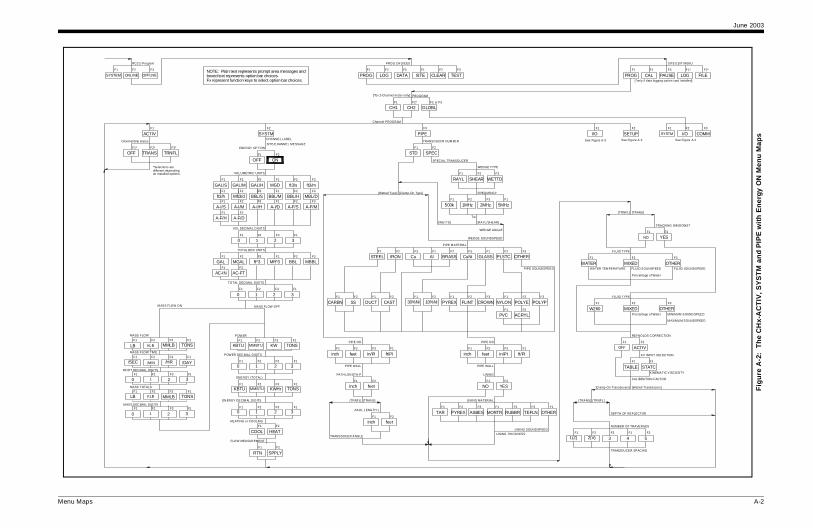
June 2003
A-2
Fig
ure
A-2
: T
he
CH
x-A
CT
IV, S
YS
TM
an
d P
IPE
wit
h E
ner
gy O
N M
enu
Map
sSETUPF2
zF3
5MHzF1
F1
I/O COMMSYSTM
F1
I/OF2 F3
PAUSEPROG CALF1 F2
LOGF3 F1*
SITE EDIT M ENU
[*only if data logging option card installed]
F2*
FILE
F3
WETTD
E TYPE
UENCY
F3
WN
SSF1 F3
PLSTCF2
OTHER
NYLONF1
POLYPF3
POLYEF2
PVCF1 F2
ACRYL
PIPE SOUNDSPEED
in/PI
ALL
E OD
F2
tF3 F1
ft/PI
F2
YESF1
ING
RUBBR
RIAL
F1
MORTR TEFLNF3F2 F1
OTHER
LINING SOUND SPEEDLINING THICKN ESS
NDSPEED
GE ANGLE
/SHEAR]
FLUID TYPE
WATER MIXEDF1 F2
OTHERF3
NO
F2F1
YES
[TRANS][TRNFL]
W260
FLUID TYPE
MIXEDF1 F2 F3
OTHERM INIMUM SOUND SPEED
M AXIMU M SOUNDSPEED
F2
STATC
ACTIVF2F1
F1
TABLE
OFF
REYNOLDS C ORRECTION
KV INPUT SELECTION
KINEMATIC VISCOSITY
CALIBRATION FACTOR
[Wetted Transducers][Clamp-On Transducers]
[TRNFL][TRANS]
DEPTH OF REFLECTOR
F2
52(V)1(Z)F1
3F2 F3 F1
4
NUMBER OF TRAVERSES
TRANSDUCER SPACING
TRACKING WIN DOWS?
FLUID SOUNDSPEEDFLUID SOUNSPEEDWATER TEM PERATURE
Percentage of Water
Percentage of Water
See Figure A-3See Figure A-3 See Figure A-4
Menu Maps
PIPEF2 F3
OFFF1
ONF2
F2
SPEC
2MH1MHz500kF1 F2
inchF1
in/PI ft/PIfeetF2 F3 F1
feetinchF1 F2
F1
inchF2
feet
ENERGY OPTION
TRANSDUCER NUM BER
SPECIAL TRANSDUCER
PIPE OD
PIPE WALL
PATH LEN GTH P
AXIAL LENGTH L
NOTE: Plain text represents prompt area messages andboxed text represents option bar choices.Fx represent function keys to select option bar choices.
CHANNEL LABELChannel/Si te status
F2*F1*
TRANSOFF
ACTIVF1
F2*F1 F2 or F3
GLOBLCH1 CH2
SITE/C HANNEL MESSAGE
Channel PROGRAM
OFFLNESYSTEM
F1
ONLINE
F2 F3
CLEARPROGF1
PROG CH OICES
F2
LOGF3
DATA SITEF1 F2 F3
TEST
RCC U Program
PROGRAM[*for 2-Channel m eter only]
STDF1
TRNFLF3*
SYSTM
RAYLF1
SHEARF2
WEDG
FREQ
PIPE M ATERIAL
IRONF1
STEEL CuF2 F3 F2
BRASSF1
Al CuNiF3
CARBN SSF2F1
PYREXF1
FLINTF2
CRO
GLA
DUCTF1
CASTF2
30%NiF1
10%NiF2
inchF1
PIPE W
PIP
fee
NO
LIN
LINING MATE
F1
TAR ASBESF3F2
PYREX
Tw
WEDGE SOU
WED
[Clamp-On Type][Wetted Type]
[WETTD] [RAYL
[TRANS][TRNFL]
TRANSDUCER ANGLE
10F1 F2
32F3 F1
ft^3MGALGALF1 F2 F3
BBLMft̂ 3F1
MBBLF2 F3
0 1F1 F2
32F3 F1
VOLUMETRIC UNITS
VOL DEC IMAL DIGITS
TOTALIZER UNITS
TOTAL DECIMAL DIGITS
F3 F1 F2 F3F1 F2
GAL/H MGD ft3/s ft3/mGAL/S GAL/MF1 F2 F3 F1 F2 F3
F1 F1F3F2 F3F2
A-F/DA-F/HF1 F2
AC-FTAC-INF1 F2
Mft3/dft3/h BBL/HBBL/S BBL/M MBL/D
A-I/MA-I/S A-F/SA-I/H A-I/D A-F/M
HEATING or COOLING
COOL HEATF1 F2
FLOW MEASUR EMENT
RTN SPPLYF1 F2
F1
3
POW ER DEC IMAL DIGITS
0F1
1F2
2F3
ENERGY (TOTAL)
F1 F2 F3 F1
KBTU KWHrMMBTU TONS
EN ERGY DECIM AL DIGITS
F1 F2 F3 F1
30 1 2
POW ER
F1 F2 F3 F1
KBTU KWMMBTU TONS
MASS FLOW OFF
MASS FLOW
F1 F2 F3 F1
LB MMLBKLB TONS
M ASS FLOW ON
MASS FLOW TIM E
F1 F2 F3 F1
/SEC /HR/MIN /DAY
M ASS DEC IMAL DIGITSF1 F2 F3 F1
MASS TOTALSF1 F2 F3 F1
LB MMLBKLB TONS
MDOT DECIMAL DIGITSF1 F2 F3 F1
0 21 3
*Selections aredi fferent dependingon installed options.
0 21 3
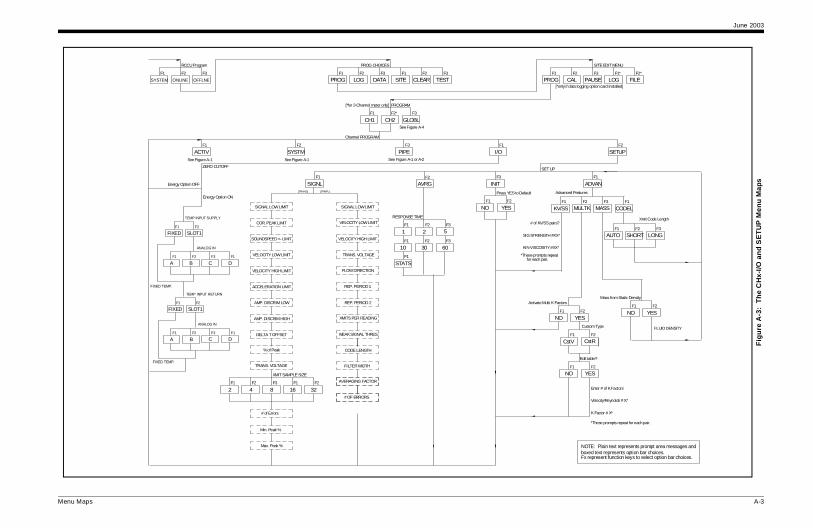
June 2003
A-3
Fig
ure
A-3
: T
he
CH
x-I/O
an
d S
ET
UP
Men
u M
aps
I/OF1
SETUPF2
SET UP
NOTE: Plain text represents prompt area messages andboxed text represents option bar choices.Fx represent function keys to select option bar choices.
F1
ADVAN
SITE EDIT MENU
[*only if data logging option card installed]
PROGF1 F3
PAUSECALF2
LOGF1*
FILEF2*
F3
INIT
Press YES to Default
1 F2
YES
Advanced Features
F1
CODELF1
KV/SS MASSF2
MULTKF3
F1
AUTO LONGF2
SHORTF3
Xmit Code Length
Activate Multi K Factors
NOF1 F2
YES
Custom Type
CstVF1 F2
CstR
Edit table?
NOF1 F2
YES
Enter # of K Factors
Velocity/Reynolds # X*
K Factor # X*
*These prompts repeat for each pair.
# of KV/SS pairs?
SIG STRENGTH #XX*
KIN VISCOSITY #XX*
*These prompts repeat for each pair.
Mass from Static Density
NOF1 F2
YES
FLUID DENSITY
Menu Maps
SYSTM PIPEF2 F3
ACTIVF1
SIGNLF1
AVRGF2
F1
1 5F2
2F3
RESPONSE TIME
F1
10 30F2
60F3
F1
STATS
ZERO CUTOFF
PROGRAM
GLOBLCH2CH1See Figure A-4
F1 F2* F3
Max. Peak %
Min. Peak %
# of Errors
[*for 2-Channel meter only]
RCCU Program
SYSTEM
F1
OFFLNE
F2
ONLINE
F3
PROGF1
PROG CHOICES
CLEARDATAF3
LOGF2
SITEF1 F2
TESTF3
Channel PROGRAM
See Figure A-1 or A-2See Figure A-1See Figure A-1
SIGNAL LOW LIMIT
COR. PEAK LIMIT
VELOCITY LOW LIMIT
SOUNDSPEED +- LIMIT
AMP. DISCRIM LOW
AMP. DISCRIM HIGH
ACCELERATION LIMIT
VELOCITY HIGH LIMIT
DELTA T OFFSET
TRANS. VOLTAGE
42F1 F2
168F3 F1
32F2
XMIT SAMPLE SIZE
% of Peak
[TRANS] [TRNFL]
SIGNAL LOW LIMIT
VELOCITY LOW LIMIT
TRANS. VOLTAGE
VELOCITY HIGH LIMIT
XMITS PER READING
REP. PERIOD 2
FLOW DIRECTION
WEAK SIGNAL THRES.
# OF ERRORS
REP. PERIOD 1
AVERAGING FACTOR
FILTER WIDTH
CODE LENGTH
NOF
Energy Option OFF
Energy Option ON
F1
FIXED SLOT1F2
TEMP INPUT RETURN
ANALOG IN
FIXED TEMP.
F1
FIXED SLOT1F2
TEMP INPUT SUPPLY
F2
B
ANALOG IN
F1
A
FIXED TEMP.
F1
DF3
C
F2
BF1
AF1
DF3
C

June 2003
A-4
Fig
ure
A-4
: T
he
Dis
pla
y (D
ATA
), G
LO
BL-
SY
ST
M, S
LO
T0
and
CO
MM
Men
u M
aps
BAUD RATE
19200F3
9600F1
600F1
300 4800F2 F3
1200F1
2400F2
F3
COMM
ROGRAM
presents prompt area messages andts option bar choices.n keys to select option bar choices.
3
F21
4
AMS
1
AVEF2
[until allchannels set up]
SITE EDIT MENU
R TESTF3
[*only if data logging option card ins talled]
PROGF1 F3
PAUSECALF2
LOGF1*
FILEF2*
Meter Address
F1
5sec
Live Data Update
30sec10secF2 F3
1minF1
6minF2
3min 12minF3 F1
CHAN NAMES
SUMCH1F1
CH2F2 F3
DIFF1
AVEF2
[only appears for 2-Channel meter]
Measurement Name
[*all diagnostic parameters appear here]
VOLUMVELF1
+TOTLF2 F3
F1
-TOTLF3F2
TIME MDOT
-MASS+MASSF1
POWER
F2 F3
F1
+ENRGF3F2
-ENRG DIAG*
tic parameters appear here]
L3
3
T
ER
3
3
*
9600F1
2400F2
4800F3
MODBUS BAUD RATE
EVENF1
NONEF2
ODDF3
MODBUS PARITY
F1
1 BITF2
2 BITS
MODBUS STOP BITS
XXX
MODBUS ADDRESS
[EXIT]
MODBUS Only
Menu Maps
F2
I/OSYSTMF1
Global P
PROGRAM
GLOBLCH2CH1F1 F2* F3
NOTE: Plain text reboxed text represenFx represent functio
OPTNF1
ERRORFF2
LCD
Global I/O
OFF 3F2F1
1F3
2F
# OF LCD PAR
CH1F1
Channel 1
CH2F2
SUMF3 F
DIF
[*for 2-Channel meter only]
RCCU Program
SYSTEM
F1
OFFLNE
F2
ONLINE
F3
PROGF1
PROG CHOICES
CLEADATAF3
LOGF2
SITEF1 F2
AVECH2CH1F1
FULL
Channel
F2 F3
SUMF1
DIFF2
Slot 0 Output A
OFFF2F1
0-20m
A
F3
4-20m
BF1 F2
SLOT0F1
I/O
SLOT1F2*
Slot 0 Outputs[*only appears if option card installed]
[only appears for 2-Channel meter]
[only appears for 2-Channel meter]
See Figure A-5
See Figure A-1 or A-2
F2F1
METRCENG
SYSTEM UNITS
10F1 F2
32F3 F1
ft^3MGALGALF1 F2 F3
BBLMft^3F1
MBBLF2 F3
0 1F1 F2
32F3 F1
VOLUMETRIC UNITS
VOL DECIMAL DIGITS
TOTALIZER UNITS
TOTAL DECIMAL DIGITS
F3 F1 F2 F3F1 F2
GAL/H MGD ft3/s ft3/mGAL/S GAL/MF1 F2 F3 F1 F2 F3
F1 F1F3F2 F3F2
A-F/DA-F/HF1 F2
AC-FTAC-INF1 F2
Mft3/dft3/h BBL/HBBL/S BBL/M MBL/D
A-I/MA-I/S A-F/SA-I/H A-I/D A-F/M
1-CHANNEL UNITS
Measurement Name
BASE [*all diagnostic parameters appear here]
VOLUMVELF1
+TOTLF2 F3
F1
-TOTLF3F2
TIME MDOT
-MASS+MASSF1
POWER
F2 F3
F1
+ENRGF3F2
-ENRG DIAG*
Measurement Name
[*all diagnos
VOLUMVELF1
+TOTF2 F
F1
-TOTLFF2
TIME MDO
-MASS+MASSF1
POW
F2 F
F1
+ENRGFF2
-ENRG DIAG
SeeFigure A-5
2-CHANNEL UNITS

June 2003
A-5
Fig
ure
A-5
: T
he
GL
OB
L-I
/O-E
RR
OR
an
d O
PT
N M
enu
Map
s
Alarm Relays
A
Slot 1 Outputs
F1 F2
B
OFFF1
HIGHF2
FAULTLOWF3 F1
YESNO
Failsafe?
F1 F2
AVE1 F2
CH2F2F1
CH1 SUM
Channel
F3 F1
DIF AVEF2
HIGH/LOW FAULT
F3
LCD
COMMF3
SITE EDIT MENU
[*only if data logging option card installed]
PROGF1 F3
PAUSECALF2
LOGF1*
FILEF2*
[only appears for 2-Channel meter]
for 2-Channel meter]
CF3 F1
D
F1
stic parameters appear here]
MDOTTIMEF2 F3
DIAG-ENRGF2 F3*
Trigger point
F1
-TOTLVEL +TOTLVOLUM
Measurement Name
F1 F2 F3
[*all diagnostic parameters appear here]
F1
MDOTTIMEF2 F3
-MASS+MASS
F2 F1
+ENRGPOWER
F3
DIAG-ENRGF2 F3*
See Figure A-4
See Figure A-4
Menu Maps
F2
LOWF1
HOLD HHIGHF3
HIGHF1
ERROR HANDLING
SLOT0
OFFF1
4-20m0-20mF2 F3
SLOT1F2*F1
I/O
Slot 1 Outputs
NOTE: Plain text represents prompt area messages andboxed text represents option bar choices.Fx represent function keys to select option bar choices.
F3
CF1
D
FULL
BASE
Analog Inputs
F1
AF2
B
Frequency Outputs
F2
BF3
C
Slot 1 (Option Card)
Input measurement
LABEL
INPUT NAME
INPUT UNITS
F2
OFFF1
TEMP SPECF3
ZERO Value
FULL Scale Value
Input measurement
RTD Inputs
F1
OFF
LABEL
F1
A
TEMPF2
BF2
FULL Scale Value
ZERO Value
F2F1
OFF FREQ
Slot 1 Outputs
FULLFULL SCALE FREQUENCY
F3
+MASS -MASSF1
Measurement Name
PULSE ON TIME
UNITS/PULSE
F1
+TOTLF2
-TOTL
F2F1
NO YES
2PATH ERROR HANDLING
CH1F1
SUMF3
Channel
CH2F2
DIFF1 F2
AVE
CH2CH1F1
Channel
F2 F3
SUMF
DIF
OPTN
CH1
I/OF1
SYSTM
F1
ERROR
Global PROGRAM
F2
F2
Global I/O
Channel PROGRAM
CH2F1 F2*
GLOBLF3
[*for 2-Channel meter only]
RCCU Program
SYSTEM
F1
OFFLNE
F2
ONLINE
F3
PROGF1
PROG CHOICES
CLEARDATAF3
LOGF2
SITEF1 F2
TESTF3
[*appears only if option card installed]
[only appears for 2-Channel meter]
[*all diagnostic parameters appear here]
Analog Outputs
Slot 1 Outputs
OFF
Totalizer Outputs
F1
TTLZRF2
AF1 F2
B
[only appears[only appears for 2-Channel meter]
CH1F1
Channel
SUMCH2F2
DIFF3 F1
AVEF2
See Figure A-1 or A-2
See Figure A-4
See Figure A-4
DF1
A
F3
CF1
D
CF3 F1
D
F3
C DF1
ZERO [*all diagno
F1
-TOTLVEL +TOTLVOLUM
Measurement Name
F1 F2 F3
F1
-MASS+MASS
F2 F1
+ENRGPOWER
F3
F1
-TOTLVEL +TOTLVOLUM
Measurement Name
F1 F2 F3
F1
MDOTTIMEF2 F3
-MASS+MASS
F2 F1
+ENRGPOWER
F3
DIAG-ENRGF2 F3*
F3
+ENRG -ENRGF1
F1
AF2
B
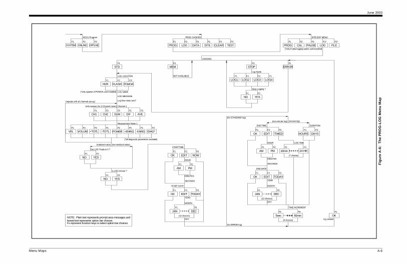
June 2003
A-6
Fig
ure
A-6
: T
he
PR
OG
-LO
G M
enu
Map
F3
STOPF1
ERROR
OG2F2
LOG3F3 F1
LOG4
Log Name
Stop Logging ?
NO YESF1 F2
TODAY
F3
DEC
YEAR
F1
JAN
DAY
MONTH
PMAM
END DATE
EDITOKF1 F2 F3
MINUTES
SECONDS
END TIME
EDITOK
F1
F1
F2
HOUR
TIMEDF2 F3
HOURSF1
DAYS
DURATION
F2
(non-circular log) (circular log)
F1F1
10min 24 HR
LOG TIME
(7 choices)
(12 choices)
TIME INCREMENT
5sec
(9 choices)
F1
60minF3
g)
SITE EDIT MENU
[*only if data logging option card installed]
PROGF1 F3
PAUSECALF2
LOGF1*
FILEF2*
OKF1
log created
Menu Maps
NOTE: Plain text represents prompt area messages andboxed text represents option bar choices.Fx represent function keys to select option bar choices.
STDF1
MEMF2
LOGGING
Measurement Name 1
VOLUMF1
VEL +ENRGF2 F3
+TOTLF1
-TOTL
LF1
LOG1NOT AVAILABLE
Log how many vars?
NOF1 F2
YES
F1
NO
Is LOG circular ?
YESF2
OK
MINUTES
SECONDS
PM
HOUR
EDIT
F1
AM
F1 F2
DAY
F2
OK
JANF1
YEAR
MONTH
EDITF1 F2
DECF3
NOWF3
F3
TODAY
STARTTIME
START DATE
(12 choices)
(totalized value) (non-totalized value)
Set LOG Totals to 0 ?
(for STANDARD lo
-ENRG DIAG*
DIF
Channel 1
CH1F1
SUMCH2F2 F3 F1 F2
AVE
F3 F1 F2
LOG LOCATION
PCMCIANVRF1 F2
FLASHF3*
LOG NAME
[repeats until all channels set up]
F2
POWER
[*all diagnostic parameters available]
(for ERROR log)
RCCU Program
SYSTEMF1
OFFLNEF2
ONLINEF3
PROGF1
PROG CHOICES
CLEARDATAF3
LOGF2
SITEF1 F2
TESTF3
LOG MESSAGE
[only appears for 2-Channel meter]
[*only appears if PCMCIA card installed]

June 2003
A-7
Fig
ure
A-7
: T
he
LO
G a
nd
CL
EA
R M
enu
Map
F2
LOG TOTALSF3
LOG2F2
LOG3F3 F1
LOG4
NAME
NAME
F2F1
NO YES
CH2F2*F1
CH1 SUMF3*
CHAN NAMES
vailable) All Logs Cleared!
CLEAR NAME
Another selction?
MOREF1
F1
NO
EXITF2
F2
YES
SITE LOG
F1
LOG4
YES
EXIT
Another selction?
All Sites Cleared !
SITE3
NAME
CLEAR NAME
NO
vailable)
MOREF1
F1
F2
SITE2 LOG1
(if more logs available)
F2
F2
SITE4F3 F1
YESNO
All Logs Cleared!
Another selction?
MOREF1
EXITF2
NAME
CLEAR NAME
F1
LOG2F1 F2
F2
LOG3F3
F1
CLEAR
F2
DIFF1*
AVEF2*
All Totals Cleared!(if more totals available)
MOREF1
EXITF2
Another selction?
PROGF1
PROG CHOICES
CLEARDATAF3
LOGF2
SITEF1 F2
TESTF3
Target CLEAR
Target Systems...
[*only for 2-Channel meter]
Menu Maps
NOTE: Plain text represents prompt area messages andboxed text represents option bar choices.Fx represent function keys to select option bar choices.
LOG4F2
LOG2F1
LOG1F3
LOG3
LOG NAMES
F3
SITEF1
F1
LOG1Uploading Header...
RCVF1
CANCELF2
F1
MOREF2
NEXTF1
EXIT
(if memory low)
EXITF1
If you wish to free...
NEXTF1
...Free in RCCU Memory
F1
ALLF2
LAST
UPLOAD DATA START
CANCELF1
RCVF2
EXITF1
LOG1F1
NAME
LOG3LOG2F2 F3
LOG4F3
EXITF1
(if no logs stored)(if log available)
<SCRNF1
STARTF2
SCRN>F3
RECRD- ENDRECRD+ <PAGE- PAGE+> EXITF1 F2 F3 F1 F2 F3
(if more logs a
(if more sites a
SITE1F1
RCCU Program
SYSTEM
F1
OFFLNE
F2
ONLINE
F3
SITE EDIT MENU
[*only if data logging option card installed]
PROGF1 F3
PAUSECALF2
LOGF1*
FILEF2*
LASTF1
There are x Log Pages...
Max number of LOGS...
(if memory OK)
Start Page #
End Page #Upld Log End Page
Uploading Log Data...
Log Data Transfer Complete
LOGXFR
F1
LOGDIR
F2
PC DIRRCCDIR
F1 F2
Offline LOG ChoiceLOG Directory?
No Logs to Display
Offline LOG Choice
LOGXFR
F1
LOGDSP
F2
NO SITES TO CLEAR

Appendix B

Data Records
Available Option Cards . . . . . . . . . . . . . . . . . . . . . . . . . . . . . . . . . B-1
Option Cards Installed . . . . . . . . . . . . . . . . . . . . . . . . . . . . . . . . . . B-2
Site Data . . . . . . . . . . . . . . . . . . . . . . . . . . . . . . . . . . . . . . . . . . . . . B-3

June 2003
Available Option Cards The XMT868 can accommodate one option card in Slot 1 and one in Slot 2. The available configurations are listed in Table B-1 below.
Table B-1: Option Card ConfigurationsCard #713- Slot # Configuration
1215-02 1 FF - 4 Frequency Outputs
1215-03 TT - 4 Totalizer Outputs
1215-04 FT - 2 Frequency Outputs/2 Totalizer Outputs
1215-05 FO - 2 Frequency Outputs
1215-06 TO - 2 Totalizer Outputs
1215-07 AA - 4 Standard Alarms
1215-08 HH - 4 Hermetic Alarms
1215-09 FA - 2 Frequency Outputs/2 Standard Alarms
1215-10 FH - 2 Frequency Outputs/2 Hermetic Alarms
1215-11 TA - 2 Totalizer Outputs/2 Standard Alarms
1215-12 TH - 2 Totalizer Outputs/2 Hermetic Alarms
1223-02 OI - 2 Current Inputs
1223-03 OR - 2 RTD Inputs
1223-04 TI - 2 Current Inputs/2 Totalizer Inputs
1223-05 TR - 2 RTD Inputs/2 Totalizer Inputs
1223-06 FI - 2 Current Inputs/2 Frequency Inputs
1223-07 FR - 2 RTD Inputs/2 Frequency Inputs
1223-08 AI - 2 Current Inputs/2 Standard Alarms
1223-09 HI - 2 Current Inputs/2 Hermetic Alarms
1223-10 AR - 2 RTD Inputs/2 Standard Alarms
1223-11 HR - 2 RTD Inputs/2 Hermetic Alarms
1225-13 CO - 2 Current Outputs
1225-14 CF - 2 Current Outputs/2 Frequency Outputs
1225-15 CT - 2 Current Outputs/2 Totalizer Outputs
1225-16 CA - 2 Current Outputs/2 Standard Alarms
1225-17 CH - 2 Current Outputs/2 Hermetic Alarms
1233-02 RR - 4 RTD Inputs
1233-03 IR - 2 RTD Inputs/2 Current Inputs
1233-04 II - 4 Current Inputs
1272-02 CI - 2 Current Outputs/2 Current Inputs
1272-03 CR - 2 Current Outputs/2 RTD Inputs
1272-04 CIR - 2 Current Outputs/1 Current Input/1 RTD Input
1146-02 2 512 KB Memory + PCMCIA Card Connector
1146-03 2 MB Memory + PCMCIA Card Connector
1310 Modbus Communications Protocol
Data Records B-1

June 2003
Option Cards Installed Whenever an option card is installed or changed in the XMT868 flow transmitter, record the type of card and any additional setup information in the appropriate row of Table B-2 below.
Table B-2: Option Cards InstalledSlot # Type of Option Card Additional Setup Information
0 Analog Outputs (A, B)
1
2
B-2 Data Records

June 2003
Site Data After the Model XMT868 flow transmitter has been installed, specific site data must be entered via the User Program, prior to operation. Record that information in Table B-3 below.
Table B-3: Site DataGeneral Information
Model # Serial #
Software Vers. Setup Date
GLOBL-SYSTM
Meter Message Vol. Dec. Digits
System Units English Metric Totalizer Units
Vol. Units Tot. Dec. Dig.
GLOBL-I/O-ERROR
Error Handling 2-Path Error No Yes
GLOBL-COMM
Meter Address MOD. Parity
Baud Rate MOD. Stop Bits
MOD. Baud Rate MOD. Address
CHx-ACTIVE
Channel 1 Channel 2 (if applicable)
Channel Status Off1 Trans Tranfl Channel Status Off1 Trans Tranfl
CHx-SYSTMChannel 1 Channel 2 (if applicable)
Channel Label Channel Label
Chan. Message2 Chan. Message2
Energy Option On Off Energy Option On Off
Vol. Units Vol. Units
Vol. Dec. Digits Vol. Dec. Digits
Totalizer Units Totalizer Units
Tot. Dec. Dig. Tot. Dec. Dig.
Mass Flow Mass Flow
Mass Flow Time Mass Flow Time
MDOT Dec. Dig. MDOT Dec. Dig.
Mass Totals Mass Totals
Mass Dec. Digits Mass Dec. Digits
Power Power
Power Dec. Dig. Power Dec. Dig.
Energy (Total) Energy (Total)
Energy Dec. Dig. Energy Dec. Dig.
Heat. or Cool. Heat. or Cool.
Flow Meas. Flow Meas.1not available for 1-Channel meter, 2”Site Message” for 1-Channel meter
Data Records B-3

June 2003
CHx-I/OZero Cutoff Temp. Input Fixed ( ) Live
Pipe/Transducer Parameters - PIPEChannel 1 Channel 2 (if applicable)
Trans. Type STD SPEC Trans. Type STD SPEC
Transducer # Transducer #
Special Transducers Special Transducers
Wedge Type Rayl Shear Wettd Wedge Type Rayl Shear Wettd
Frequency Hz Frequency Hz
Trans. Tw Trans. Tw
Wedge Angle Wedge Angle
Wedge Sndspd Wedge Sndspd
Pipe Material Pipe Material
All Clamp-On and Wetted Transducers All Clamp-On and Wetted Transducers
Pipe O.D. Pipe O.D.
Pipe Wall Pipe Wall
Path Length (P) Path Length (P)
Axial Length (L) Axial Length (L)
Trans. Angle Trans. Angle
Lining Yes No Lining Yes No
Lining Material Lining Material
Lining Sndspd Lining Sndspd
Lining Thickness Lining Thickness
Track. Window. Yes No Track. Window. Yes No
Fluid Type Fluid Type
Other/Sndspd Other/Sndspd
% of Water % of Water
Reynolds Corr. Off Active Reynolds Corr. Off Active
KV Input Sel. Table Static KV Input Sel. Table Static
Kin. Visc. Kin. Visc.
Cal. Factor Cal. Factor
# of Traverses # of Traverses
Trans. Spacing Trans. Spacing
Depth of Reflect. Depth of Reflect.
CHx-SETUP-AVRGResponse Time
Table B-3: Site Data (cont.)
B-4 Data Records
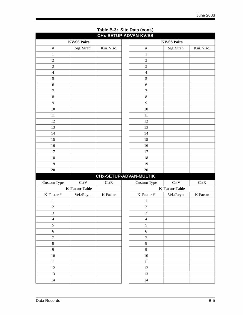
June 2003
CHx-SETUP-ADVAN-KV/SSKV/SS Pairs KV/SS Pairs
# Sig. Stren. Kin. Visc. # Sig. Stren. Kin. Visc.
1 1
2 2
3 3
4 4
5 5
6 6
7 7
8 8
9 9
10 10
11 11
12 12
13 13
14 14
15 15
16 16
17 17
18 18
19 19
20 20
CHx-SETUP-ADVAN-MULTIKCustom Type CstV CstR Custom Type CstV CstR
K-Factor Table K-Factor Table
K-Factor # Vel./Reyn. K Factor K-Factor # Vel./Reyn. K Factor
1 1
2 2
3 3
4 4
5 5
6 6
7 7
8 8
9 9
10 10
11 11
12 12
13 13
14 14
Table B-3: Site Data (cont.)
Data Records B-5
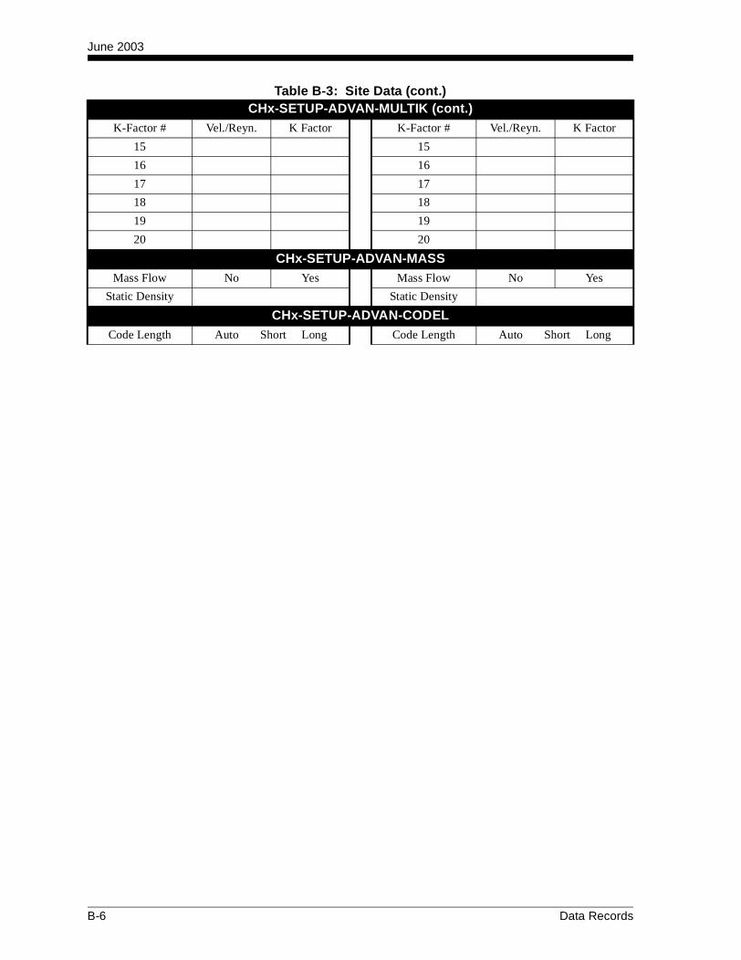
June 2003
CHx-SETUP-ADVAN-MULTIK (cont.)K-Factor # Vel./Reyn. K Factor K-Factor # Vel./Reyn. K Factor
15 15
16 16
17 17
18 18
19 19
20 20
CHx-SETUP-ADVAN-MASSMass Flow No Yes Mass Flow No Yes
Static Density Static Density
CHx-SETUP-ADVAN-CODELCode Length Auto Short Long Code Length Auto Short Long
Table B-3: Site Data (cont.)
B-6 Data Records

Appendix C

Instrument Data Manager
The CHx-STATUS, SYSTEM and INPUT/OUTPUTMenu Maps . . . . . . . . . . . . . . . . . . . . . . . . . . . . . . . . . . . . . . . . . . . C-1
The CHx-PIPE Menu Map. . . . . . . . . . . . . . . . . . . . . . . . . . . . . . . . C-2
The CHx-SETUP Menu Map. . . . . . . . . . . . . . . . . . . . . . . . . . . . . . C-3
The GLOBAL-SYSTEM, I/O-ERROR HANDLING, SLOT0, DISPLAY and COMM PORT Menu Maps. . . . . . . . . . . . . . . . . . . . C-4
The GLOBL-I/O-OPTIONS-SLOT1 Menu Map. . . . . . . . . . . . . . . . C-5
The PAUSE MEASUREMENT and FILE Menu Maps . . . . . . . . . . C-6
The LOG EDIT Menu Map . . . . . . . . . . . . . . . . . . . . . . . . . . . . . . . C-7
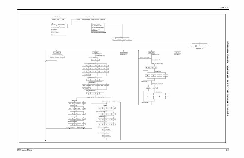
June 2003
C-1
Fig
ure
C-1
: T
he
CH
x-S
TAT
US
, SY
ST
EM
an
d IN
PU
T/O
UT
PU
T M
enu
Map
s
Input/OutputSystem Comm Port
Input/Output SET UP
FIXED SLOT1
TEMP INPUT RETURN
ZERO CUTOFF
ANALOG IN
MP.
FIXED SLOT1
TEMP INPUT SUPPLY
B
ANALOG IN
A
P.
DC
BA DC
Energy Option ON
on OFF
See Figure C-3
See Figure C-4
IDM Menu Maps
TransitDisabled
[*for 2-Channel meter only]
[*only if data logging option card installed]
IDM Main Menu Meter Window Menu
System Upload/Download Edit Functions Real Time
Connect to a New Instrument
Select an Existing Instrument
Scan Network for Instruments
Preferences
Dial Modem
Hang Up Modem
Exit
Global Data Help
*
SITE EDIT MENU
CALIBRATION/TEST
PAUSE MEASUREMENT
LOG EDIT MENU
FILE MENU*
Channel 1 Channel 2* Global
Status Pipe Parameters
Transflection
OFF ON
GAL/H MGD ft3/s ft3/mGAL/S GAL/M
ENERGY OPTION
VOLUMETRIC UNITS
CHANNEL LABEL
SITE/CHANNEL MESSAGE
10 32
VOL DECIMAL DIGITS
Mft3/dft3/h BBL/HBBL/S BBL/M MBL/D
A-I/MA-I/S A-F/SA-I/H A-I/D A-F/M
A-F/DA-F/H
ft^3MGALGAL BBLMft^3 MBBL
TOTALIZER UNITS
AC-FTAC-IN
0 1 32
TOTAL DECIMAL DIGITS
System
ENERGY OPTION ON ENERGY OPTION OFFMASS FLOW
LB MMLBKLB TONS
/DAY
MASS FLOW TIME
/SEC /MIN /HR
MDOT DECIMAL DIGITS
0 1 2 3
MASS TOTALS
LB TONSMMLBKLB
MASS DECIMAL DIGITS
0 1 2 3
Mass Flow On
ENERGY OPTION OFF ENERGY OPTION ON
Mass Flow Off
3
POWER DECIMAL DIGITS
0 1 2
HEATING or COOLING
COOL HEAT
ENERGY (TOTAL)
KBTU KWHrMMBTU TONS
ENERGY DECIMAL DIGITS
30 1 2
FLOW MEASUREMENT
RTN SPPLY
FIXED TE
POWER
kBTU MMBTU TONSkWHr
FIXED TEM
Energy Opti
See Figure C-2

June 2003
C-2
Fig
ure
C-2
: T
he
CH
x-P
IPE
Men
u M
ap
Input/OutputSystem Comm Port
FLUID TYPE
WATER OIL ETHMETH LN2 OTHERFREON
LUBENORML SEA CRUDE
FLUID SOUNDSPEEDWATER TEMPERATURE
NO YES
[TRNFL]
W260W100
FLUID TYPE
OIL OTHERMINIMUM SOUNDSPEED
MAXIMUM SOUNDSPEED
STATC
ACTIV
TABLE
OFF
REYNOLDS CORRECTION
KV INPUT SELECTION
KINEMATIC VISCOSITY
CALIBRATION FACTOR
[Wetted Transducers][Clamp-On Transducers]
[TRNFL][TRANS]
DEPTH OF REFLECTOR
52(V)1(Z) 3 4
NUMBER OF TRAVERSES
TRANSDUCER SPACING
TRACKING WINDOWS?
[TRANS]
Input/Output SET UP
Hz
TC OTHER
LON POLYPPOLYE
C ACRYL
PIPE SOUNDSPEED
ER
See Figure C-1 See Figure C-3
See Figure C-4
IDM Menu Maps
[*for 2-Channel meter only]
[*only if data logging option card installed]
IDM Main Menu Meter Window Menu
System Upload/Download Edit Functions Real Time
Connect to a New Instrument
Select an Existing Instrument
Scan Network for Instruments
Preferences
Dial Modem
Hang Up Modem
Exit
Global Data Help
*
SITE EDIT MENU
CALIBRATION/TEST
PAUSE MEASUREMENT
LOG EDIT MENU
FILE MENU*
Channel 1 Channel 2* Global
FLUID TYPE
WATER MIXED OTHER
NO YES
[TRANS][TRNFL]
W260
FLUID TYPE
MIXED OTHERMINIMUM SOUNDSPEED
MAXIMUM SOUNDSPEED
STATC
ACTIV
TABLE
OFF
REYNOLDS CORRECTION
KV INPUT SELECTION
KINEMATIC VISCOSITY
CALIBRATION FACTOR
[Wetted Transducers][Clamp-On Transducers]
[TRNFL][TRANS]
DEPTH OF REFLECTOR
52(V)1(Z) 3 4
NUMBER OF TRAVERSES
TRANSDUCER SPACING
TRACKING WINDOWS?
FLUID SOUNDSPEEDFLUID SOUNSPEEDWATER TEMPERATURE
Percentage of Water
Percentage of Water
Status System Pipe Param eters
SPEC
2MHz1MHz500k 5M
inch in/PI ft/PIfeet
feetinch
inch feet
TRANSDUCER NUMBER
SPECIAL TRANSDUCER
PIPE OD
PIPE WALL
PATH LENGTH P
AXIAL LENGTH L
STD
RAYL SHEAR WETTD
WEDGE TYPE
FREQUENCY
PIPE MATERIAL
IRONSTEEL Cu BRASSAl CuNi
CARBN SS PYREX FLINT CROWN
GLASS PLS
DUCT CAST 30%Ni 10%Ni NY
PV
in/PIinch
PIPE WALL
PIPE OD
feet ft/PI
YESNO
LINING
RUBBR
LINING MATERIAL
TAR ASBESPYREX MORTR TEFLN OTH
LINING SOUNDSPEEDLINING THICKNESS
Tw
WEDGE SOUNDSPEED
WEDGE ANGLE
[Clamp-On Type][Wetted Type]
[WETTD] [RAYL/SHEAR]
[TRANS][TRNFL]
TRANSDUCER ANGLE
Energy Option OFFEnergy Option ON
See Figure C-1See Figure C-1

June 2003
C-3
Fig
ure
C-3
: T
he
CH
x-S
ET
UP
Men
u M
ap
Input/OutputSy stem Com m Port
ut/Output SET UP
Advanced Features
C ode Length
Xm it Code Length
Autom atic Shor t Code Long Code
Mass from Static Dens?
NO YES
Mass Flow from Static
Flu id Density
*
prev iously
Figure C-1
See Figure C -4
IDM Menu Maps
[*for 2-C hann el met er only]
[*only if dat a logg in g op tio n card installed]
IDM Main Menu Meter W indow M enu
System Upload/Dow nload Edit Functions R eal Time
Connect to a New Instrum ent
Selec t an Ex isting Instrum ent
Scan N etwork for Instrum ents
Preferences
Dial M odem
Hang U p M odemEx it
Global D ata H elp
*
SIT E ED IT MENU
C ALIBRATION /TEST
PAUSE MEASUR EM ENT
LOG EDIT M ENU
F ILE MEN U*
Channel 1 C hannel 2* Global
InpStatus Pipe ParametersSystem
1 52
RESPONSE TIME
Max. Peak %
Min. Peak %
# of Errors
10 30 60 STATS
42
16
8
32
XMIT SAMPLE SIZE
SIGNAL LOW LIMIT
COR. PEAK LIMIT
VELOCITY LOW LIMIT
SOUNDSPEED +- LIMIT
AMP. DISCRIM LOW
AMP. DISCRIM HIGH
ACCELERATION LIMIT
VELOCITY HIGH LIMIT
DELTA T OFFSET
TRANS. VOLTAGE
% of Peak
[TR N FL ] [TRAN S]
SIGNAL LOW LIMIT
VELOCITY LOW LIMIT
TRANS. VOLTAGE
VELOCITY HIGH LIMIT
XMITS PER READING
REP. PERIOD 2
FLOW DIRECTION
WEAK SIGNAL THRES.
# OF ERRORS
REP. PERIOD 1
AVERAGING FACTOR
FILTER LENGTH
CODE LENGTH
Signal V averaging Defaul t Setup
Press YES to Default
NO YES
Enter KV/SS T able Multiple K Factors
Activate Multi K Fact?
NO YES
C us tom T ype
Custom (Velocity) C ustom (R eyn #)
Edit table?
NO YES
Enter # of K F ac tors
R ey nolds/Velocity #
K F actor #*
*R epeat for the # of K Factors entered
# of KV/SS pairs
Sig Strength #*
Kin Viscosity #*
*R epeats for #of pairs entered previously. Enter in ascending order.
See F igure C -1 See Figure C-1 See Figure C-2 See

June 2003
C-4
Fig
ure
C-4
: T
he
GL
OB
AL
-SY
ST
EM
, I/O
-ER
RO
R H
AN
DL
ING
, SL
OT
0, D
ISP
LA
Y a
nd C
OM
M P
OR
T M
enu
Map
s
IDM Main Menu Meter Window Menu
Comm Port
BAUD RATE
192009600600300 48001200 2400
Meter Address
Display
4
AMS
AVE
[until all channels set up]
ic parameters appear here]
MDOT
RG DIAG*
ME
MODBUS BAUD RATE
96002400 4800
MODBUS PARITY
EVENNONE ODD
MODBUS STOP BITS
1 BIT 2 BITS
MODBUS ADDRESS
XXX
MODBUS Only
IDM Menu Maps
[*for 2-Channel meter only]
[*only if data logging option card installed]
System Upload/Download Edit Functions Real Time
Connect to a New Instrument
Select an Existing Instrument
Scan Network for Instruments
Preferences
Dial Modem
Hang Up Modem
Exit
Global Data Help
*
SITE EDIT MENU
CALIBRATION/TEST
PAUSE MEASUREMENT
LOG EDIT MENU
FILE MENU*
Input/OutputSystem
Channel 1 Channel 2* Global
GAL/H MGD ft3/s ft3/mGAL/S GAL/M
SYSTEM UNITS
VOLUMETRIC UNITS
METER MESSAGE
10 32
VOL DECIMAL DIGITS
Mft3/dft3/h BBL/HBBL/S BBL/M MBL/D
A-I/MA-I/S A-F/SA-I/H A-I/D A-F/M
A-F/DA-F/H
ft̂ 3MGALGAL BBLMft̂ 3 MBBL
TOTALIZER UNITS
AC-FTAC-IN
0 1 32
TOTAL DECIMAL DIGITS
English Metric OptionsError Handling
Force Low Force HighHold Last Value Force High High
Error Handling
2PATH ERROR HANDLING
YES NO
AVECH2
Measurement Name
CH1
BASE
FULL
Channel
SUM DIF
Slot 0 Output A
OFF 0-20m
A
4-20m
B
SLOT0 SLOT1
[*all diagnostic parameters appear here]
Slot 0 Outputs
[only appears for 2-Channel meter]
LCD
OFF 31 2
# OF LCD PAR
CH1
Channel 1
CH2 SUM DIF
[*all diagnost
[only appears for 2-Channel meter]
VOLUMVEL -TOTL+TOTL
-EN
TI
-MASS+MASS +ENRGPOWER
VOLUMVEL -TOTL+TOTL MDOT
-ENRG DIAG*
TIME
-MASS+MASS +ENRGPOWER
See Figures C-1 thru C-3
See Figure C-5
1-CHANNEL UNITS
2-CHANNEL UNITS

June 2003
C-5
Fig
ure
C-5
: T
he
GL
OB
L-I
/O-O
PT
ION
S-S
LO
T1
Men
u M
ap
IDM Main Menu Meter Window Menu
Comm Port
y
Alarm Relays
A
Slot 1 Outputs
B
OFF HIGH FAULTLOW
YESNO
F ailsafe?
T rigger point
AVEDIF
CH2CH1 SUM
C hannel
DIF AVE
HIGH /LOW FAULT
[only appears for 2-C hannel m eter ]
M easurem ent N am e
[*a ll diagnostic param eters appear here]
ears for 2-C hannel m eter ]
agnostic parameters appear here]
C D
D
MDOT
-ENRG DIAG*
TIME
VOLUMVEL -TOTL+TOTL MDOT
-ENRG DIAG*
TIME
-MASS+MASS +ENRGPOWER
e C-4
See Figure C-4
IDM Menu Maps
[*for 2-Channel meter only]
[*only if data logging option card installed]
System Upload/Download Edit Functions Real Time
Connect to a New Instrument
Select an Existing Instrument
Scan Network for Instruments
Preferences
Dial Modem
Hang Up Modem
Exit
Global Data Help
*
SITE EDIT MENU
CALIBRATION/TEST
PAUSE MEASUREMENT
LOG EDIT MENU
FILE MENU*
Input/OutputSystem
Channel 1 Channel 2* Global
Options DisplaError Handling
SLOT0
Measurem ent N ame
OFF 4-20m0-20m
A B
SLOT1
Slot 1 Outputs
FULL
BASE
Analog Inputs
A B
Frequency Outputs
B C
Slot 1 (Option Card)
Input measurem ent
OFF SPEC
LABEL
IN PUT NAM E
IN PUT UN IT S
TEMP
BASE Value
FU LL Scale Value
Input m easurem ent
RT D Inputs
OFF
LABEL
A
TEMP
B
FULL Scale Value
Z ERO Value
OFF FREQ
Slot 1 Outputs
BASE
F ULLFU LL SC ALE F REQU ENC Y
+ENRG -ENRG
M easurem ent N am e
PULSE ON T IME
UN ITS/PULSE
+TOTL -TOTL
CH1 SUM
Channel
CH2 DIF AVE
CH2CH1
C hannel
SUM
appears only if option card ins ta l led
[only appears for 2-Channel meter]
[*a ll d iagnos tic parameters appear here]
Analog Outputs
Slot 1 Outputs
OFF
T otalizer Outputs
TTLZR
A B
[only app[only appears for 2-C hannel m eter ]
CH1
C hannel
SUMCH2 DIF AVE
M eas urement Nam e
[* al l d i
A
C D
C D
C D
+MASS -MASS
VOLUMVEL -TOTL+TOTL MDOT
-ENRG DIAG*
TIME
-MASS+MASS +ENRGPOWER
VOLUMVEL -TOTL+TOTL
-MASS+MASS +ENRGPOWER
C D
See Figure C-4
See Figure C-4
See Figur

June 2003
C-6
Fig
ure
C-6
: T
he
PA
US
E M
EA
SU
RE
ME
NT
an
d F
ILE
Men
u M
aps
FILE LOCATION
Repair Disk
PCMCIA*VR FLASH[*only appears if PCMCIA card installed]
ATTEMPT REPAIR
ttempt repair Proceed with repair
REPAIR COMPLETED
MEASURE FLOW STOP MEASUREMENT
PAUSE: Measure Flow
IDM Menu Maps
[*only if data logging option card installed]
IDM Main Menu Meter Window Menu
System Upload/Download Edit Functions Real Time
Connect to a New Instrument
Select an Exis ting Instrument
Scan Network for Instruments
Preferences
Dial Modem
Hang Up ModemExit
Global Data Help
*
SITE EDIT MENU
CALIBRATION/TEST
PAUSE MEASUREMENT
LOG EDIT MENUFILE MENU
FILE LOCATION
FILE LOCATION
PCMCIA*NVR FLASH
DIRECTORY
ENTER FILENAME
[*only appears ifPCMCIA card installed]
Upload File Delete File
SELECT NEW FILE LOCATION
DIRECTORY
ENTER FILENAMEN
Do not a
*

June 2003
C-7
Fig
ure
C-7
: T
he
LO
G M
enu
Map
G2 LOG3 LOG4
Log Name
Stop Logging ?
O YES
TODAY
DEC
YEAR
JAN
DAY
MONTH
PMAM
END DATE
EDITOK
MINUTES
SECONDS
END TIME
EDITOK
HOUR
TIMED HOURS DAYS
DURATION
(non-c ircular log) (c ircular log)
10min 24 HR
LOG TIME
(7 choices)
(12 choices)
TIME INCREMENT
5sec(9 choices)
60min
)
OKlog created
Stop Logging Create Error Log
IDM Menu Maps
[*only if data logging option card installed]
IDM Main Menu Meter Window Menu
System Upload/Download Edit Functions Real Time
Connect to a New Instrument
Select an Existing Instrument
Scan Network for Instruments
Preferences
Dial Modem
Hang Up Modem
Exit
Global Data Help
*
SITE EDIT MENU
CALIBRATION/TEST
PAUSE MEASUREMENT
LOG EDIT MENU
FILE MENU*
Measurement Name 1
LOLOG1
N
Log Memory
Log how many vars?
OK
MINUTES
SECONDS
PM
HOUR
EDIT
AM
DAY
OK
JAN
YEAR
MONTH
EDIT
DEC
NOW
TODAY
STARTTIME
START DATE
(12 choices)
(for STANDARD log
DIF
Channel 1
CH1 SUMCH2 AVE
NO YES
NO
Is LOG circular ?
YES
(totalized value) (non-totalized value)
Set LOG Totals to 0 ?
LOG LOCATION
PCMCIA*NVR FLASH
LOG NAME
[repeats until all channels set up]
[*all diagnostic parameters available]
(for ERROR log)
LOG MESSAGE
[only appears for 2-Channel meter]
[*only appears if PCMCIA card installed]
Create Standard Log
VOLUMVEL +TOTL
+MASS -MASS
DIAG*+ENRG -ENRG
MDOT-TOTL TIME
POWER
Memory
June 2003
Index
AAbbreviations, Volumetric Units . . . . . . . . . . . . . . . 1-12, 1-14, 1-52, 1-54ACTIV Sub-Menu . . . . . . . . . . . . . . . . . . . . 1-11
Menu Map . . . . . . . . . . . . . . . . . . . . A-1, A-2ADVAN Option . . . . . . . . . . . . . . . . . . . . . . 1-47
CODEL Option . . . . . . . . . . . . . . . . . . . . 1-50KV/SS Option . . . . . . . . . . . . . . . . . . . . . 1-47MASS Option. . . . . . . . . . . . . . . . . . . . . . 1-50MULTK Option . . . . . . . . . . . . . . . . . . . . 1-48
Alarms Card, Setting Up . . . . . . . . . . . . . . . 1-68Analog Inputs Card, Setting Up . . . . . . . . . . 1-64Analog Outputs
Slot 0, Setting Up . . . . . . . . . . . . . . . . . . . 1-59Slot 1, Setting Up . . . . . . . . . . . . . . . . . . . 1-62Units Options . . . 1-61, 1-63, 1-70, 1-73, 1-76
AVRG Option. . . . . . . . . . . . . . . . . . . 1-41, 1-46Axial Length, Entering. . . . . . . . . . . . . . . . . 1-24
BBacklight
See Brightness and ContrastBasic Programming
Minimum Requirements. . . . . . . . . . . . . . . 1-6Brightness and Contrast, Adjusting . . . . . . . . 2-1
CCHx Menu . . . . . . . . . . . . . . . . . . . . . . . . . . 1-11
ACTIV Sub-Menu . . . . . . . . . . . . . . . . . . 1-11Menu Map (Energy Off) . . . A-1, A-2
I/O Sub-Menu. . . . . . . . . . . . . . . . . . . . . . 1-31Menu Map . . . . . . . . . . . . . . . . . . . .A-3
Input/Output Sub-MenuMenu Map for IDM . . . . . . . . . . . .C-1
Menu Map for IDM . . . . . . . . . . . . . . . . . .C-1Menu Map (Energy On) . . . . . . . . . . . . . . .A-2Menu Map (Energy Off). . . . . . . . . . . . . . .A-1PIPE Sub-Menu . . . . . . . . . . . . . . . . . . . . 1-20
Menu Map . . . . . . . . . . . . . . . A-1, A-2Menu Map for IDM . . . . . . . . . . . .C-2
SETUP Sub-Menu . . . . . . . . . . . . . . . . . . 1-34Menu Map . . . . . . . . . . . . . . . . . . . .A-3Menu Map for IDM . . . . . . . . . . . .C-3
C (cont.)CHx Menu (cont.)
STATUS Sub-MenuMenu Map for IDM . . . . . . . . . . . C-1
SYSTEM Sub-MenuMenu Map for IDM . . . . . . . . . . . C-1
SYSTM Sub-Menu . . . . . . . . . . . . . . . . . .1-12Menu Map (Energy Off) . . . . . . . A-1Menu Map (Energy On) . . . . . . . . A-2
CHx-PIPE . . . . . . . . . . . . . . . . . . . . . . . . . . .1-20Menu Map . . . . . . . . . . . . . . . . . . . . . . . . . C-2
CHx-STATUSMenu Map . . . . . . . . . . . . . . . . . . . . . . . . . C-1See Also ACTIVE Sub-Menu
CLEAR MenuMenu Map . . . . . . . . . . . . . . . . . . . . . . . . . A-7
Clearing RCCU Memory . . . . . . . . . . . . . . . .5-1Log File . . . . . . . . . . . . . . . . . . . . . . . . . . . .5-3Site File . . . . . . . . . . . . . . . . . . . . . . . . . . . .5-2
Clearing Totalizers . . . . . . . . . . . . . . . . . . . . .5-6Clearing Transmitter Memory . . . . . . . . . . . .5-4
Log File . . . . . . . . . . . . . . . . . . . . . . . . . . . .5-5Site Data . . . . . . . . . . . . . . . . . . . . . . . . . . .5-5
COMM PORTMenu Map . . . . . . . . . . . . . . . . . . . . . . . . . C-4
COMM Sub-Menu . . . . . . . . . . . . . . . . . . . .1-77Communications Failure . . . . . . . . . . . . . . . . .1-6Contrast and Brightness, Adjusting . . . . . . . .2-1
Index 1
June 2003
Index (cont.)
DDataDisplaying. . . . . . . . . . . . . . . . . . . . . . . . . . 2-6Displaying Using IDM . . . . . . . . . . . . . . . . 2-9
DATA Menu . . . . . . . . . . . . . . . . . . . . . . . . . . 2-6Menu Map. . . . . . . . . . . . . . . . . . . . . . . . . A-4
Data Record . . . . . . . . . . . . . . . . . . . . . . . . . 3-23Depth of Reflector, Entering. . . . . . . . . . . . . 1-30Diagnostic Parameters . . . 1-61, 1-63, 1-70, 1-76, 2-5, 2-9DISPLAY Sub-Menu
Menu Map. . . . . . . . . . . . . . . . . . . . . . . . . C-4Display
Parameter Options . . . . . . . 2-5, 2-8, 3-5, 3-14See Also Liquid Crystal Display
DISPLAY Sub-MenuMenu Map for IDM . . . . . . . . . . . . . . . . . C-4
Displaying Data . . . . . . . . . . . . . . . . . . . 2-1, 2-6Adjusting Contrast and Brightness . . . . . . . 2-1Log File, Reading . . . . . . . . . . . . . . . . . . . 3-23Menu Map. . . . . . . . . . . . . . . . . . . . . . . . . A-4Menu Map (IDM) . . . . . . . . . . . . . . . . . . . C-4Navigating Log Screens, Reading . . . . . . 3-26
EEnergy Option, Activating . . . . . . . . . . . . . . 1-12EPROM
See User Program . . . . . . . . . . . . . . . . . . . . 1-6Error Handling . . . . . . . . . . . . . . . . . . . . . . . 1-56
2-Path . . . . . . . . . . . . . . . . . . . . . . . . . . . . 1-57ERROR Response Options . . . . . . . . . . . . . . 1-56
FFault Light Indicator . . . . . . . . . . . . . . . . . . . . 1-7FILE
Menu Map. . . . . . . . . . . . . . . . . . . . . . . . . C-6FILE Menu
Menu Map for IDM . . . . . . . . . . . . . . . . . C-6Fluid Type, Entering . . . . . . . . . . . . . . . . . . . 1-25Fluid Type, Selecting . . . . . . . . . . . . . 1-26, 1-27Frequency Card, Setting Up . . . . . . . . . . . . . 1-74
GGLOBAL Menu (IDM)
COMM PORT Sub-MenuMenu Map. . . . . . . . . . . . . . . . . . . . C-4
Input/Output Sub-MenuSLOT0 Menu Map. . . . . . . . . . . . . C-4SLOT1 Menu Map. . . . . . . . . . . . . C-5
Menu Map . . . . . . . . . . . . . . . . . . . . . . . . . C-4SYSTEM Sub-Menu
Menu Map. . . . . . . . . . . . . . . . . . . . C-4GLOBAL-SYSTEM
Menu Map . . . . . . . . . . . . . . . . . . . . . . . . . C-4See Also GLOBL-SYSTM Sub-Menu
GLOBL Menu . . . . . . . . . . . . . . . . . . . . . . . 1-51COMM Sub-Menu. . . . . . . . . . . . . . . . . . 1-77
Menu Map. . . . . . . . . . . . . . . . . . . . A-4I/O Sub-Menu . . . . . . . . . . . . . . . . . . . . . 1-55
ERROR OptionMenu Map . . . . . . . . . . . . . . . . A-5
Error Option . . . . . . . . . . . . . . . . . 1-56LCD Option . . . . . . . . . . . . . . . . . . 2-2OPTN Option . . . . . . . . . . . . . . . . 1-59
Menu Map . . . . . . . . . . . . . . . . A-5SLOT0
Menu Map . . . . . . . . . . . . . . . . A-4Menu Map . . . . . . . . . . . . . . . . . . . . . . . . . A-4SYSTM Sub-Menu . . . . . . . . . . . . . 1-52, A-4
GLOBL-I/O-ERROR . . . . . . . . . . . . . . . . . 1-56Menu Map . . . . . . . . . . . . . . . . . . . . . . . . . A-5
GLOBL-I/O-OPTIONS-SLOT1Menu Map . . . . . . . . . . . . . . . . . . . . . . . . . C-5
GLOBL-SYSTM Sub-Menu . . . . . . . . . . . . 1-52Green Light Indicator . . . . . . . . . . . . . . . . . . 1-7
HHeader Record . . . . . . . . . . . . . . . . . . . . . . . 3-23
2 Index
June 2003
Index (cont.)
II/O (GLOBL) Sub-Menu . . . . . . . . . . . . . . . 1-55Error Option . . . . . . . . . . . . . . . . . . . . . . . 1-56LCD Option . . . . . . . . . . . . . . . . . . . . . . . . 2-2OPTN Option . . . . . . . . . . . . . . . . . . . . . . 1-59
I/O Sub-Menu. . . . . . . . . . . . . . . . . . . . . . . . 1-31Temperature Input, Entering . . . . . . . . . . 1-32Zero Cutoff Value, Entering . . . . . . . . . . . 1-31
I/O-ERROR HANDLINGMenu Map . . . . . . . . . . . . . . . . . . . . . . . . .C-4
INIT Option . . . . . . . . . . . . . . . . . . . . . . . . . 1-46Initial Setup
Data Table . . . . . . . . . . . . . . . . . . . . . . . . .B-3INPUT/OUTPUT (IDM)
Menu Map . . . . . . . . . . . . . . . . . . . . . . . . .C-1Instrument Data Manager. . . . . . . . . . . . . . . . 2-9
Communication Setup . . . . . . . . . . . . . . . 1-77Instrument Program
See User Program
KKeypad (RCCU), Using . . . . . . . . . . . . . . . . . 1-2Keys
Table of Functions . . . . . . . . . . . . . . . . . . . 1-3Kinematic Viscosity Input, Selecting. . . . . . 1-29KV Input Selection, Selecting . . . . . . . . . . . 1-29
LLCD
See Liquid Crystal DisplayLCD Option . . . . . . . . . . . . . . . . . . . . . . . . . .2-2Light Indicators . . . . . . . . . . . . . . . . . . . . . . . .1-7Lining, Selecting . . . . . . . . . . . . . . . . . . . . . .1-25Liquid Crystal Display (Transmitter) . . . . . . .2-1
Adjusting Contrast and Brightness . . . . . . .2-1Setting Up . . . . . . . . . . . . . . . . . . . . . . . . . .2-2
LOGMenu Map . . . . . . . . . . . . . . . A-7, C-7 (IDM)
LOG EDIT MenuMenu Map . . . . . . . . . . . . . . . . . . . . . . . . . C-7
Log FileClearing. . . . . . . . . . . . . . . . . . . . . . . . 5-3, 5-5Navigating Log Screens . . . . . . . . . . . . . .3-26Navigating Screens . . . . . . . . . . . . . 3-23, 3-26Reading . . . . . . . . . . . . . . . . . . . . . . . . . . .3-23Structure . . . . . . . . . . . . . . . . . . . . . . . . . .3-23
LOG MenuChecking XMT Memory. . . . . . . . . . . . . .3-18STOP Sub-Menu . . . . . . . . . . . . . . . . . . . .3-19Upload File to RCCU . . . . . . . . . . . . . . . .3-19
Logging DataTime Increment . . . . . . . . . . . . . . . . . . . . . 3-11
Index 3

June 2003
Index (cont.)
MMass Flow Option, Activating . . . . . . . . . . . 1-15Measurements
Parameter Options . . . . . . . 2-5, 2-8, 3-5, 3-14MEM Sub-Menu. . . . . . . . . . . . . . . . . . . . . . 3-18Memory
Clearing Log File . . . . . . . . . . . . . . . . 5-3, 5-5Clearing RCCU. . . . . . . . . . . . . . . . . . . . . . 5-1Clearing Site Data. . . . . . . . . . . . . . . . . . . . 5-5Clearing Site File . . . . . . . . . . . . . . . . . . . . 5-2Clearing Transmitter . . . . . . . . . . . . . . . . . . 5-4
Menu Map. . . . . . . . . . . . . . . . . . . . . . . . . . . A-4ACTIV Sub-Menu (Energy Off). . . . A-1, A-2CHx Menu (Energy Off). . . . . . . . . . . . . . A-1CHx Menu (Energy On) . . . . . . . . . . . . . . A-2CHx Menu (IDM) . . . . . . . . . . . . . . . . . . . C-1CLEAR Menu . . . . . . . . . . . . . . . . . . . . . . A-7COMM PORT Sub-Menu (IDM) . . . . . . . C-4COMM Sub-Menu . . . . . . . . . . . . . . . . . . A-4DATA Menu . . . . . . . . . . . . . . . . . . . . . . . . 2-6
Menu Map . . . . . . . . . . . . . . . . . . . A-4DISPLAY Sub-Menu
Menu Map (IDM) . . . . . . . . . . . . . C-4FILE Menu . . . . . . . . . . . . . . . . . . . . . . . . C-6GLOBAL Sub-Menu (IDM). . . . . . . . . . . C-4GLOBL Sub-Menu . . . . . . . . . . . . . . . . . . A-4I/O (GLOBL) Sub-Menu
ERROR Option . . . . . . . . . . . . . . . A-5OPTN Option. . . . . . . . . . . . . . . . . A-5SLOT0 . . . . . . . . . . . . . . . . . . . . . . A-4
I/O Sub-Menu . . . . . . . . . . . . . . . . . . . . . . A-3Input/Output (GLOBAL) Sub-Menu (IDM)
ERROR HANDLING . . . . . . . . . C-4SLOT0 . . . . . . . . . . . . . . . . . . . . . . C-4SLOT1 . . . . . . . . . . . . . . . . . . . . . . C-5
M (cont.)Menu Map (cont.)
Input/Output Sub-Menu (IDM) . . . . . . . . . C-1LOG EDIT Menu (IDM) . . . . . . . . . . . . . . C-7LOG Sub-Menu . . . . . . . . . . . . . . . . . . . . . A-6PAUSE MEASUREMENT Menu (IDM) . C-6PIPE Sub-Menu (IDM) . . . . . . . . . . . . . . . A-1PIPE Sub-Menu (Energy Off) . . . . . . . . . . A-2PIPE Sub-Menu (Energy On) . . . . . . . . . . C-2SETUP Sub-Menu . . . . . . . . . A-3, C-3 (IDM)STATUS Sub-Menu (IDM) . . . . . . . . . . . . C-1SYSTEM (GLOBAL) Sub-Menu (IDM) . C-4SYSTEM Sub-Menu (IDM) . . . . . . . . . . . C-1SYSTM (GLOBL) Sub-Menu . . . . . . . . . . A-4SYSTM Sub-Menu (Energy Off) . . . . . . . A-1SYSTM Sub-Menu (Energy On) . . . . . . . . A-2
MODBUS . . . . . . . . . . . . . . . . . . . . . . . . . . 1-77MODBUS Register . . . . . . . . . . . . . . . . . . . 1-80
NNumber of Traverses, Entering . . . . . . . . . . 1-29
OOnline
See User Program, AccessingOption Card
Alarms . . . . . . . . . . . . . . . . . . . . . . . . . . . 1-68Analog Inputs . . . . . . . . . . . . . . . . . . . . . 1-64Analog Outputs . . . . . . . . . . . . . . . . . . . . 1-62Frequency . . . . . . . . . . . . . . . . . . . . . . . . 1-74RTD Inputs . . . . . . . . . . . . . . . . . . . . . . . 1-67Setup Information Table . . . . . . . . . . . . . . B-2Totalizer . . . . . . . . . . . . . . . . . . . . . . . . . . 1-71Totalizer/Frequency . . . . . . . . . . . . . . . . . 1-74
OPTN Options . . . . . . . . . . . . . . . . . . . . . . . 1-59Menu Map . . . . . . . . . . . . . . . . . . . . . . . . . A-5
4 Index

June 2003
Index (cont.)
PParameter Options . . . . . . . . . 2-5, 2-8, 3-5, 3-14Path Length, Entering. . . . . . . . . . . . . . . . . . 1-24PAUSE MEASUREMENT (IDM)
Menu Map . . . . . . . . . . . . . . . . . . . . . . . . .C-6Pipe Material, Entering . . . . . . . . . . . . . . . . 1-22Pipe OD, Entering . . . . . . . . . . . . . . . . . . . . 1-23PIPE Sub-Menu . . . . . . . . . . . . . . . . . . . . . . 1-20
Axial Length, Entering. . . . . . . . . . . . . . . 1-24Depth of Reflector, Entering . . . . . . . . . . 1-30Fluid Type, Selecting . . . . . . . . . . . . . . . . 1-27KV Input Selection, Selecting . . . . . . . . . 1-29Lining, Selecting . . . . . . . . . . . . . . . . . . . 1-25Number of Traverses . . . . . . . . . . . . . . . . 1-29Path Length, Entering. . . . . . . . . . . . . . . . 1-24Pipe Material, Entering . . . . . . . . . . . . . . 1-22Pipe OD, Entering . . . . . . . . . . . . . . . . . . 1-23Reynolds Correction, Entering. . . . . . . . . 1-28Tracking Window, Activating . . . . . . . . . 1-26Transducer Angle, Entering . . . . . . . . . . . 1-25Transducer Spacing, Entering . . . . . . . . . 1-30
Printing Data . . . . . . . . . . . . . . . . . . . . . . . . . 4-1PRNT Menu . . . . . . . . . . . . . . . . . . . . . . . . . . 4-1PROG Menu. . . . . . . . . . . . . . . . . . . . . . . . . 1-10
CHx Menu . . . . . . . . . . . . . . . . . . . . . . . . 1-11GLOBL Menu . . . . . . . . . . . . . . . . . . . . . 1-51LOG Sub-Menu
Menu Map . . . . . . . . . . . . . . . . . . . .A-6PROG-LOG
Menu Map . . . . . . . . . . . . . . . . . . . . . . . . .A-6Programming
User Program, Accessing . . . . . . . . . . . . . . 1-7
RRCCU
Clearing Menu . . . . . . . . . . . . . . . . . . . . . . 5-1Communications Failure . . . . . . . . . . . . . . 1-6Log File
Navigating Screens. . . . . . . . . . . . 3-26Log File, Reading . . . . . . . . . . . 3-23
Uploading Log File . . . . . . . . . . . . . . . . . 3-19
R (cont.)Reading a Log File . . . . . . . . . . . . . . . . . . . .3-23
Navigating Screens . . . . . . . . . . . . . 3-23, 3-26Record
Data . . . . . . . . . . . . . . . . . . . . . . . . . . . . . .3-23Header . . . . . . . . . . . . . . . . . . . . . . . . . . . .3-23
Red Light Indicators . . . . . . . . . . . . . . . . . . . .1-7Reynolds Correction, Entering . . . . . . . . . . .1-28RS232 Port, RS485 Port
See Serial PortRTD Inputs Card, Setting Up . . . . . . . . . . . .1-67
SSend/Receive Light Indicators . . . . . . . . . . . .1-7Serial Communications. . . . . . . . . . . . . . . . .1-77SETUP Sub-Menu . . . . . . . . . . . . . . . . . . . .1-34
ADVAN Option. . . . . . . . . . . . . . . . . . . . .1-47CODEL Option . . . . . . . . . . . . . . .1-50KV/SS Option . . . . . . . . . . . . . . . .1-47MASS Option . . . . . . . . . . . . . . . .1-50MULTK Option. . . . . . . . . . . . . . .1-48
AVRG Option . . . . . . . . . . . . . . . . . 1-41, 1-46INIT Option . . . . . . . . . . . . . . . . . . . . . . .1-46SIGNL Option
TransFlection Values . . . . . . . . . .1-41Transit-Time Values . . . . . . . . . . .1-35
SIGNL Option. . . . . . . . . . . . . . . . . . . . . . . .1-35TransFlection Values. . . . . . . . . . . . . . . . .1-41Transit-Time Values . . . . . . . . . . . . . . . . .1-35
Site Data, Clearing . . . . . . . . . . . . . . . . . . . . .5-5Site File, Clearing . . . . . . . . . . . . . . . . . . . . . .5-2Slot 0
Menu Map . . . . . . . . . . . . . . . . . . . . . . . . . C-4Output MeasurementOptions . . . . . . . . 1-61, 1-63, 1-70, 1-73, 1-76Setting Up . . . . . . . . . . . . . . . . . . . . . . . . .1-59
Slot Number . . . . . . . . . . . . . . . . . . . . . . . . .1-55Special Transducers . . . . . . . . . . . . . . . . . . .1-20Startup
See Basic Programming . . . . . . . . . . . . . . .1-6Stopping a Log . . . . . . . . . . . . . . . . . . . . . . .3-19SYSTEM
Menu Map . . . . . . . . . . . . . . . . . . . . . A-1, C-1SYSTM (CHx) Sub-Menu . . . . . . . . . . . . . .1-12SYSTM (GLOBL) Sub-Menu . . . . . . . . . . .1-52
Index 5
June 2003
Index (cont.)
TTemperature Input, Entering . . . . . . . . . . . . . 1-32Totalizer Card, Setting Up . . . . . . . . . . . . . . 1-71Totalizer/Frequency Card
Setting Up . . . . . . . . . . . . . . . . . . . . . . . . . 1-74Totalizers, Clearing. . . . . . . . . . . . . . . . . . . . . 5-6Tracking Window, Activating. . . . . . . . . . . . 1-26Transducer Spacing, Entering. . . . . . . . . . . . 1-30Transducers
Special. . . . . . . . . . . . . . . . . . . . . . . . . . . . 1-20TransFlection Method, Activating . . . . . . . . 1-11Transit-Time Method, Activating . . . . . . . . . 1-11Transmitter
Clearing Menu . . . . . . . . . . . . . . . . . . . . . . 5-4Displaying Data . . . . . . . . . . . . . . . . . . . . . 2-1LCD, Setting Up . . . . . . . . . . . . . . . . . . . . . 2-2Light Indicators. . . . . . . . . . . . . . . . . . . . . . 1-7Uploading File to RCCU . . . . . . . . . . . . . 3-19
UUploading Log File to RCCU. . . . . . . . . . . . 3-19User Program
Accessing . . . . . . . . . . . . . . . . . . . . . . . . . . 1-7CHx Menu . . . . . . . . . . . . . . . . . . . . . . . . 1-11
ACTIV Sub-Menu . . . . . . . . . . . . 1-11I/O Sub-Menu . . . . . . . . . . . . . . . . 1-31PIPE Sub-Menu. . . . . . . . . . . . . . . 1-20Setup Sub-Menu . . . . . . . . . . . . . . 1-34SYSTM Sub-Menu . . . . . . . . . . . . 1-12
DATA Menu . . . . . . . . . . . . . . . . . . . . . . . . 2-6GLOBL Menu. . . . . . . . . . . . . . . . . . . . . . 1-51
I/O Sub-Menu . . . . . . . . . . . 1-55, 1-77Error Option . . . . . . . . . . . . . . 1-56LCD Option. . . . . . . . . . . . . . . . 2-2OPTN Option . . . . . . . . . . . . . 1-59
SYSTM Sub-Menu . . . . . . . . . . . . 1-52Minimum Requirements . . . . . . . . . . . . . . . 1-6Overview. . . . . . . . . . . . . . . . . . . . . . . . . . . 1-6PROG Menu . . . . . . . . . . . . . . . . . . . . . . . 1-10Sub-Menus . . . . . . . . . . . . . . . . . . . . . . . . . 1-1
VVolumetric Units
Abbreviations . . . . . . . 1-12, 1-14, 1-52, 1-54Selecting . . . . . . . . . . . 1-12, 1-14, 1-52, 1-54Table of Options . . . . . 1-12, 1-14, 1-52, 1-54
ZZERO Cutoff Value, Entering . . . . . . . . . . . 1-31
6 Index

TÜV ESSENISO 9001
U.S.
TÜV
DECLARATIONOF
CONFORMITY
We, GE PanametricsShannon Industrial Estate
Shannon, Co. ClareIreland
declare under our sole responsibility that the
IGM878 Industrial Gas Ultrasonic Flow Transmitter
XGF868 Flare Gas Ultrasonic Flow TransmitterXGM868 Multi-Purpose Gas Ultrasonic Flow Transmitter
XGN868 Natural Gas Ultrasonic Flow Transmitter
XGS868 Steam Mass Ultrasonic Flow TransmitterXMT868 Liquid Ultrasonic Flow Transmitter
to which this declaration relates, are in conformity with the following standards:
• EN 61326:1998, Class A, Annex A, Continuous Unmonitored Operation
• EN 61010-1:1993 + A2:1995, Overvoltage Category II, Pollution Degree 2
following the provisions of the 89/336/EEC EMC Directive and the 73/23/EEC Low Voltage Directive.
The units listed above and any transducers supplied with them (spoolpieces are addressed under a separate declaration of conformity) do not bear CE marking for the Pressure Equipment Directive, as they are supplied in accordance with Article 3, Section 3 (sound engineering practices and codes of good workmanship) of the Pressure Equipment Directive 97/23/EC for DN<25.
Shannon - June 1, 2002
Mr. James Gibson
GENERAL MANAGER
CERT-DOC Rev G4 5/28/02

TÜV ESSENISO 9001
U.S.
TÜV
DECLARATIONDE
CONFORMITE
Nous, GE PanametricsShannon Industrial Estate
Shannon, Co. ClareIreland
déclarons sous notre propre responsabilité que les
IGM878 Industrial Gas Ultrasonic Flow Transmitter
XGF868 Flare Gas Ultrasonic Flow TransmitterXGM868 Multi-Purpose Gas Ultrasonic Flow Transmitter
XGN868 Natural Gas Ultrasonic Flow Transmitter
XGS868 Steam Mass Ultrasonic Flow TransmitterXMT868 Liquid Ultrasonic Flow Transmitter
rélatif á cette déclaration, sont en conformité avec les documents suivants:
• EN 61326:1998, Class A, Annex A, Continuous Unmonitored Operation
• EN 61010-1:1993 + A2:1995, Overvoltage Category II, Pollution Degree 2
suivant les régles de la Directive de Compatibilité Electromagnétique 89/336/EEC et de la Directive Basse Tension 73/23/EEC.
Les matériels listés ci-dessus ainsi que les transducteurs pouvant être livrés avec (les manchettes faisant l'objet d'une déclaration de conformité séparée) ne portent pas le marquage CE de la directive des équipements sous pression, car ils sont fournis en accord avec la directive 97/23/EC des équipements sous pression pour les DN<25, Article 3, section 3 qui concerne les pratiques et les codes de bonne fabrication pour l'ingénierie du son.
Shannon - June 1, 2002
Mr. James Gibson
DIRECTEUR GÉNÉRAL
CERT-DOC Rev G4 5/28/02

TÜV ESSENISO 9001
U.S.
TÜV
KONFORMITÄTS-ERKLÄRUNG
Wir, GE PanametricsShannon Industrial Estate
Shannon, Co. ClareIreland
erklären, in alleiniger Verantwortung, daß die Produkte
IGM878 Industrial Gas Ultrasonic Flow Transmitter
XGF868 Flare Gas Ultrasonic Flow TransmitterXGM868 Multi-Purpose Gas Ultrasonic Flow Transmitter
XGN868 Natural Gas Ultrasonic Flow Transmitter
XGS868 Steam Mass Ultrasonic Flow TransmitterXMT868 Liquid Ultrasonic Flow Transmitter
folgende Normen erfüllen:
• EN 61326:1998, Class A, Annex A, Continuous Unmonitored Operation
• EN 61010-1:1993 + A2:1995, Overvoltage Category II, Pollution Degree 2
gemäß den Europäischen Richtlinien, Niederspannungsrichtlinie Nr.: 73/23/EWG und EMV-Richtlinie Nr.: 89/336/EWG.
Die oben aufgeführten Geräte und zugehörige, mitgelieferte Schallwandler (Messrohre werden in einer separaten Konformitätserklärung behandelt) tragen keine CE-Kennzeichnung gemäß der Druckgeräte-Richtlinie, da sie in Übereinstimmung mit Artikel 3, Absatz 3 (gute Ingenieurpraxis) der Druckgeräte-Richtlinie 97/23/EG für DN<25 geliefert werden.
Shannon - June 1, 2002
Mr. James Gibson
GENERALDIREKTOR
CERT-DOC Rev G4 5/28/02

WORLDWIDEOFFICES
MAIN OFFICES: GE PANAMETRICS INTERNATIONAL OFFICES:USAGE Panametrics221 Crescent St., Suite 1Waltham, MA 02453-3497USATelephone: 781-899-2719Toll-Free: 800-833-9438Fax: 781-894-8582E-mail: [email protected]: www.gepower.com/panametricsISO 9001 Certified
IrelandGE PanametricsShannon Industrial EstateShannon, Co. ClareIrelandTelephone 353-61-470200Fax 353-61-471359E-mail [email protected] 9002 Certified
March 2003
AustraliaP.O. Box 234Gymea N.S.W. 2227AustraliaTelephone 61 (02) 9525 4055Fax 61 (02) 9526 2776E-mail [email protected]
AustriaWaldgasse 39A-1100 WienAustriaTelephone +43-1-602 25 34Fax +43-1-602 25 34 11E-mail [email protected]
BeneluxPostbus 1113870 CC HoevelakenThe NetherlandsTelephone +31 (0) 33 253 64 44Fax +31 (0) 33 253 72 69E-mail [email protected]
FranceBP 10611 Rue du Renard92253 La Garenne Colombes CedexFranceTelephone 33 (0) 1 47-82-42-81Fax 33 (0) 1 47-86-74-90E-mail [email protected]
GermanyMess-und PruftechnikRobert-Bosch-Straße 20a65719 HofheimGermanyTelephone +49-6122-8090Fax +49-6122-8147E-mail [email protected]
ItalyVia Feltre, 19/A20132 MilanoItalyTelephone 02-2642131Fax 02-26414454E-mail [email protected]
Japan2F, Sumitomo Bldg.5-41-10, Koishikawa, Bunkyo-KuTokyo 112-0002JapanTelephone 81 (03) 5802-8701Fax 81 (03) 5802-8706E-mail [email protected]
KoreaKwanghee Bldg., 201, 644-2Ilwon-dong, Kangnam-KuSeoul 135-945KoreaTelephone 82-2-445-9512Fax 82-2-445-9540E-mail [email protected]
SpainDiamante 4228224 Pozuelo de AlarconMadridSpainTelephone 34 (91) 351.82.60Fax 34 (91) 351.13.70E-mail [email protected]
SwedenBox 160S147 23 TumbaSwedenTelephone +46-(0)8-530 685 00Fax +46-(0)8-530 357 57E-mail [email protected]
Taiwan7th Fl 52, Sec 3 Nan-Kang RoadTaipei, TaiwanROCTelephone 02-2788-3656Fax 02-2782-7369E-mail [email protected]
United KingdomUnit 2, Villiers Court40 Upper Mulgrave RoadCheamSurrey SM2 7AJEnglandTelephone 020-8643-5150Fax 020-8643-4225E-mail [email protected]

USA
GE Panametrics221 Crescent Street, Suite 1Waltham, MA 02453-3497Telephone: (781) 899-2719Toll-free: (800) 833-9438Fax: (781) 894-8582E-Mail: [email protected]: www.gepower.com/panametrics
Ireland
GE PanametricsShannon Industrial EstateShannon, County ClareIrelandTelephone: 353-61-470200Fax: 353-61-471359E-Mail: [email protected]