GE Infrastructure Sensing - Ultrasonic Flow Meters, Water
120
GE Infrastructure Sensing Model CTF878 Clamp-On Tag Flowmeter Startup Guide
Transcript of GE Infrastructure Sensing - Ultrasonic Flow Meters, Water

GE InfrastructureSensing
Model CTF878Clamp-On Tag Flowmeter
Startup Guide

GE InfrastructureSensing
Model CTF878Clamp-On Tag Flowmeter
Startup Guide910-254UA1September 2004

July 2004
Warranty Each instrument manufactured by GE Infrastructure Sensing, Inc. is warranted to be free from defects in material and workmanship. Liability under this warranty is limited to restoring the instrument to normal operation or replacing the instrument, at the sole discretion of GE Infrastructure Sensing, Inc. Fuses and batteries are specifically excluded from any liability. This warranty is effective from the date of delivery to the original purchaser. If GE Infrastructure Sensing, Inc. determines that the equipment was defective, the warranty period is:
• one year for general electronic failures of the instrument
• one year for mechanical failures of the sensor
If GE Infrastructure Sensing, Inc. determines that the equipment was damaged by misuse, improper installation, the use of unauthorized replacement parts, or operating conditions outside the guidelines specified by GE Infrastructure Sensing, Inc., the repairs are not covered under this warranty.
The warranties set forth herein are exclusive and are in lieu ofall other warranties whether statutory, express or implied(including warranties of merchantability and fitness for aparticular purpose, and warranties arising from course ofdealing or usage or trade).
Return Policy If a GE Infrastructure Sensing, Inc. instrument malfunctions within the warranty period, the following procedure must be completed:
1. Notify GE Infrastructure Sensing, Inc., giving full details of the problem, and provide the model number and serial number of the instrument. If the nature of the problem indicates the need for factory service, GE Infrastructure Sensing, Inc. will issue a RETURN AUTHORIZATION number (RA), and shipping instructions for the return of the instrument to a service center will be provided.
2. If GE Infrastructure Sensing, Inc. instructs you to send your instrument to a service center, it must be shipped prepaid to the authorized repair station indicated in the shipping instructions.
3. Upon receipt, GE Infrastructure Sensing, Inc. will evaluate the instrument to determine the cause of the malfunction.
Then, one of the following courses of action will then be taken:
• If the damage is covered under the terms of the warranty, the instrument will be repaired at no cost to the owner and returned.
• If GE Infrastructure Sensing, Inc. determines that the damage is not covered under the terms of the warranty, or if the warranty has expired, an estimate for the cost of the repairs at standard rates will be provided. Upon receipt of the owner’s approval to proceed, the instrument will be repaired and returned.
iii

September 2004
Table of Contents
Chapter 1: Features and Capabilities
Overview . . . . . . . . . . . . . . . . . . . . . . . . . . . . . . . . . . . . . . . . . . . . . . . . . . . . . . . . . . . . . . . . . . . .1-1Electronics Package . . . . . . . . . . . . . . . . . . . . . . . . . . . . . . . . . . . . . . . . . . . . . . . . . . . . . . . .1-1Transducers . . . . . . . . . . . . . . . . . . . . . . . . . . . . . . . . . . . . . . . . . . . . . . . . . . . . . . . . . . . . . . .1-3
Theory of Operation . . . . . . . . . . . . . . . . . . . . . . . . . . . . . . . . . . . . . . . . . . . . . . . . . . . . . . . . . . .1-3
Chapter 2: Installation
Introduction . . . . . . . . . . . . . . . . . . . . . . . . . . . . . . . . . . . . . . . . . . . . . . . . . . . . . . . . . . . . . . . . . .2-1Unpacking . . . . . . . . . . . . . . . . . . . . . . . . . . . . . . . . . . . . . . . . . . . . . . . . . . . . . . . . . . . . . . . . . . .2-1System Parts . . . . . . . . . . . . . . . . . . . . . . . . . . . . . . . . . . . . . . . . . . . . . . . . . . . . . . . . . . . . . . . . .2-2Tools for Installation . . . . . . . . . . . . . . . . . . . . . . . . . . . . . . . . . . . . . . . . . . . . . . . . . . . . . . . . . . .2-3Installing the Electronics Console . . . . . . . . . . . . . . . . . . . . . . . . . . . . . . . . . . . . . . . . . . . . . . . . .2-4
Locating the Electronics Console . . . . . . . . . . . . . . . . . . . . . . . . . . . . . . . . . . . . . . . . . . . . . .2-4Mounting the Electronics Console . . . . . . . . . . . . . . . . . . . . . . . . . . . . . . . . . . . . . . . . . . . . .2-4Wiring the Electronics Console . . . . . . . . . . . . . . . . . . . . . . . . . . . . . . . . . . . . . . . . . . . . . . .2-4
Installing Transducer Support . . . . . . . . . . . . . . . . . . . . . . . . . . . . . . . . . . . . . . . . . . . . . . . . . . . .2-6Clamping Fixture . . . . . . . . . . . . . . . . . . . . . . . . . . . . . . . . . . . . . . . . . . . . . . . . . . . . . . . . . .2-6Damping Material . . . . . . . . . . . . . . . . . . . . . . . . . . . . . . . . . . . . . . . . . . . . . . . . . . . . . . . . . .2-6
Installing a CFT-V Clamping Fixture . . . . . . . . . . . . . . . . . . . . . . . . . . . . . . . . . . . . . . . . . . . . . .2-7Locating the CFT-V Clamping Fixture. . . . . . . . . . . . . . . . . . . . . . . . . . . . . . . . . . . . . . . . . .2-7Preparing for CFT-V Clamping Fixture Installation. . . . . . . . . . . . . . . . . . . . . . . . . . . . . . . .2-8Mounting the CFT-V Clamping Fixture . . . . . . . . . . . . . . . . . . . . . . . . . . . . . . . . . . . . . . . .2-12
Installing a CFT-PI Clamping Fixture . . . . . . . . . . . . . . . . . . . . . . . . . . . . . . . . . . . . . . . . . . . . .2-13Locating the CFT-PI Clamping Fixture . . . . . . . . . . . . . . . . . . . . . . . . . . . . . . . . . . . . . . . .2-13Preparing for CFT-PI Clamping Fixture Installation . . . . . . . . . . . . . . . . . . . . . . . . . . . . . .2-14Mounting the CFT-PI Clamping Fixture . . . . . . . . . . . . . . . . . . . . . . . . . . . . . . . . . . . . . . .2-15Applying DMP-1 Damping Material for a CFT-PI Clamping Fixture . . . . . . . . . . . . . . . . .2-17
Applying DMP-3 Damping Material. . . . . . . . . . . . . . . . . . . . . . . . . . . . . . . . . . . . . . . . . . . . . .2-19Installing the PDJ Pipe Damping Jacket . . . . . . . . . . . . . . . . . . . . . . . . . . . . . . . . . . . . . . . . . . .2-21Installing Transducers . . . . . . . . . . . . . . . . . . . . . . . . . . . . . . . . . . . . . . . . . . . . . . . . . . . . . . . . .2-23
Preparing for Installation with a CFT-V Clamping Fixture . . . . . . . . . . . . . . . . . . . . . . . . .2-23Mounting Transducers . . . . . . . . . . . . . . . . . . . . . . . . . . . . . . . . . . . . . . . . . . . . . . . . . . . . .2-24Wiring the Transducers. . . . . . . . . . . . . . . . . . . . . . . . . . . . . . . . . . . . . . . . . . . . . . . . . . . . .2-26
Installing Temperature and Pressure Transmitters. . . . . . . . . . . . . . . . . . . . . . . . . . . . . . . . . . . .2-30Locating . . . . . . . . . . . . . . . . . . . . . . . . . . . . . . . . . . . . . . . . . . . . . . . . . . . . . . . . . . . . . . . .2-30Mounting. . . . . . . . . . . . . . . . . . . . . . . . . . . . . . . . . . . . . . . . . . . . . . . . . . . . . . . . . . . . . . . .2-30Wiring . . . . . . . . . . . . . . . . . . . . . . . . . . . . . . . . . . . . . . . . . . . . . . . . . . . . . . . . . . . . . . . . . .2-30
PC Board Connections. . . . . . . . . . . . . . . . . . . . . . . . . . . . . . . . . . . . . . . . . . . . . . . . . . . . . . . . .2-32Wiring the 0/4-20 mA Analog Outputs. . . . . . . . . . . . . . . . . . . . . . . . . . . . . . . . . . . . . . . . .2-32Wiring the Serial Port . . . . . . . . . . . . . . . . . . . . . . . . . . . . . . . . . . . . . . . . . . . . . . . . . . . . . .2-32
Option Card Wiring . . . . . . . . . . . . . . . . . . . . . . . . . . . . . . . . . . . . . . . . . . . . . . . . . . . . . . . . . . .2-34Wiring an Alarms Option Card. . . . . . . . . . . . . . . . . . . . . . . . . . . . . . . . . . . . . . . . . . . . . . .2-34Wiring a 0/4-20 mA Analog Inputs Option Card . . . . . . . . . . . . . . . . . . . . . . . . . . . . . . . . .2-35Wiring a Totalizer/Frequency Outputs Option Card. . . . . . . . . . . . . . . . . . . . . . . . . . . . . . .2-36Wiring an RTD Inputs Option Card . . . . . . . . . . . . . . . . . . . . . . . . . . . . . . . . . . . . . . . . . . .2-37Wiring a 0/4-20 mA Analog Outputs Option Card. . . . . . . . . . . . . . . . . . . . . . . . . . . . . . . .2-37
v

September 2004
Table of Contents (cont.)
Chapter 3: Initial Setup
Introduction . . . . . . . . . . . . . . . . . . . . . . . . . . . . . . . . . . . . . . . . . . . . . . . . . . . . . . . . . . . . . . . . . 3-1Powering Up. . . . . . . . . . . . . . . . . . . . . . . . . . . . . . . . . . . . . . . . . . . . . . . . . . . . . . . . . . . . . . . . . 3-1Using the Screen . . . . . . . . . . . . . . . . . . . . . . . . . . . . . . . . . . . . . . . . . . . . . . . . . . . . . . . . . . . . . 3-2Using the Keypad. . . . . . . . . . . . . . . . . . . . . . . . . . . . . . . . . . . . . . . . . . . . . . . . . . . . . . . . . . . . . 3-4Programming Site Data . . . . . . . . . . . . . . . . . . . . . . . . . . . . . . . . . . . . . . . . . . . . . . . . . . . . . . . . 3-6
Entering the Program Menu . . . . . . . . . . . . . . . . . . . . . . . . . . . . . . . . . . . . . . . . . . . . . . . . . 3-6Entering Transducer Parameters . . . . . . . . . . . . . . . . . . . . . . . . . . . . . . . . . . . . . . . . . . . . . . 3-7Entering Pipe Parameters. . . . . . . . . . . . . . . . . . . . . . . . . . . . . . . . . . . . . . . . . . . . . . . . . . . 3-11Entering Fluid Types and Speeds . . . . . . . . . . . . . . . . . . . . . . . . . . . . . . . . . . . . . . . . . . . . 3-15Entering Path Parameters. . . . . . . . . . . . . . . . . . . . . . . . . . . . . . . . . . . . . . . . . . . . . . . . . . . 3-16Entering Analog Outputs . . . . . . . . . . . . . . . . . . . . . . . . . . . . . . . . . . . . . . . . . . . . . . . . . . . 3-18Entering Digital Outputs . . . . . . . . . . . . . . . . . . . . . . . . . . . . . . . . . . . . . . . . . . . . . . . . . . . 3-21Entering a Calibration Factor . . . . . . . . . . . . . . . . . . . . . . . . . . . . . . . . . . . . . . . . . . . . . . . 3-23
Chapter 4: Operation
Introduction . . . . . . . . . . . . . . . . . . . . . . . . . . . . . . . . . . . . . . . . . . . . . . . . . . . . . . . . . . . . . . . . . 4-1Displaying and Configuring Data . . . . . . . . . . . . . . . . . . . . . . . . . . . . . . . . . . . . . . . . . . . . . . . . 4-1
Format Option . . . . . . . . . . . . . . . . . . . . . . . . . . . . . . . . . . . . . . . . . . . . . . . . . . . . . . . . . . . . 4-2View Option . . . . . . . . . . . . . . . . . . . . . . . . . . . . . . . . . . . . . . . . . . . . . . . . . . . . . . . . . . . . . 4-3Limits Option. . . . . . . . . . . . . . . . . . . . . . . . . . . . . . . . . . . . . . . . . . . . . . . . . . . . . . . . . . . . . 4-3Measurement Option . . . . . . . . . . . . . . . . . . . . . . . . . . . . . . . . . . . . . . . . . . . . . . . . . . . . . . . 4-5Customizing the Display Screen . . . . . . . . . . . . . . . . . . . . . . . . . . . . . . . . . . . . . . . . . . . . . . 4-6Accessing Meter Data —The About Option . . . . . . . . . . . . . . . . . . . . . . . . . . . . . . . . . . . . 4-11
vi

September 2004
Table of Contents (cont.)
Chapter 5: Specifications
Features . . . . . . . . . . . . . . . . . . . . . . . . . . . . . . . . . . . . . . . . . . . . . . . . . . . . . . . . . . . . . . . . . . . . .5-1Built-In Flow Computer . . . . . . . . . . . . . . . . . . . . . . . . . . . . . . . . . . . . . . . . . . . . . . . . . . . . .5-1Data Logging. . . . . . . . . . . . . . . . . . . . . . . . . . . . . . . . . . . . . . . . . . . . . . . . . . . . . . . . . . . . . .5-1Display Functions . . . . . . . . . . . . . . . . . . . . . . . . . . . . . . . . . . . . . . . . . . . . . . . . . . . . . . . . . .5-1PC-Interface Software. . . . . . . . . . . . . . . . . . . . . . . . . . . . . . . . . . . . . . . . . . . . . . . . . . . . . . .5-1
General System Specifications . . . . . . . . . . . . . . . . . . . . . . . . . . . . . . . . . . . . . . . . . . . . . . . . . . .5-2Hardware Configuration . . . . . . . . . . . . . . . . . . . . . . . . . . . . . . . . . . . . . . . . . . . . . . . . . . . . .5-2Package Options:. . . . . . . . . . . . . . . . . . . . . . . . . . . . . . . . . . . . . . . . . . . . . . . . . . . . . . . . . . .5-2Physical Characteristics . . . . . . . . . . . . . . . . . . . . . . . . . . . . . . . . . . . . . . . . . . . . . . . . . . . . .5-2Flow Range and Accuracy (% of reading) . . . . . . . . . . . . . . . . . . . . . . . . . . . . . . . . . . . . . . .5-2
System Electronics Specifications. . . . . . . . . . . . . . . . . . . . . . . . . . . . . . . . . . . . . . . . . . . . . . . . .5-3User Interface . . . . . . . . . . . . . . . . . . . . . . . . . . . . . . . . . . . . . . . . . . . . . . . . . . . . . . . . . . . . .5-3User I/O. . . . . . . . . . . . . . . . . . . . . . . . . . . . . . . . . . . . . . . . . . . . . . . . . . . . . . . . . . . . . . . . . .5-3Power Input . . . . . . . . . . . . . . . . . . . . . . . . . . . . . . . . . . . . . . . . . . . . . . . . . . . . . . . . . . . . . . .5-4Environmental Requirements . . . . . . . . . . . . . . . . . . . . . . . . . . . . . . . . . . . . . . . . . . . . . . . . .5-4Regulatory, Safety, Certifications. . . . . . . . . . . . . . . . . . . . . . . . . . . . . . . . . . . . . . . . . . . . . .5-4
Transducer, Preamplifier and Fixture Specifications . . . . . . . . . . . . . . . . . . . . . . . . . . . . . . . . . .5-5Ultrasonic Flow Transducers . . . . . . . . . . . . . . . . . . . . . . . . . . . . . . . . . . . . . . . . . . . . . . . . .5-5Receive Transducer Preamplifier . . . . . . . . . . . . . . . . . . . . . . . . . . . . . . . . . . . . . . . . . . . . . .5-5Clamping Fixtures. . . . . . . . . . . . . . . . . . . . . . . . . . . . . . . . . . . . . . . . . . . . . . . . . . . . . . . . . .5-5Transducer Fixtures. . . . . . . . . . . . . . . . . . . . . . . . . . . . . . . . . . . . . . . . . . . . . . . . . . . . . . . . .5-5
Pipe Specifications . . . . . . . . . . . . . . . . . . . . . . . . . . . . . . . . . . . . . . . . . . . . . . . . . . . . . . . . . . . .5-6Materials . . . . . . . . . . . . . . . . . . . . . . . . . . . . . . . . . . . . . . . . . . . . . . . . . . . . . . . . . . . . . . . . .5-6Sizes . . . . . . . . . . . . . . . . . . . . . . . . . . . . . . . . . . . . . . . . . . . . . . . . . . . . . . . . . . . . . . . . . . . .5-6Wall Thickness . . . . . . . . . . . . . . . . . . . . . . . . . . . . . . . . . . . . . . . . . . . . . . . . . . . . . . . . . . . .5-6Pressure Requirements . . . . . . . . . . . . . . . . . . . . . . . . . . . . . . . . . . . . . . . . . . . . . . . . . . . . . .5-6
Appendix A: CE Mark Compliance
Introduction . . . . . . . . . . . . . . . . . . . . . . . . . . . . . . . . . . . . . . . . . . . . . . . . . . . . . . . . . . . . . . . . . A-1Wiring . . . . . . . . . . . . . . . . . . . . . . . . . . . . . . . . . . . . . . . . . . . . . . . . . . . . . . . . . . . . . . . . . . . . . A-1External Grounding . . . . . . . . . . . . . . . . . . . . . . . . . . . . . . . . . . . . . . . . . . . . . . . . . . . . . . . . . . . A-1
Appendix B: Data Records
Option Cards Installed . . . . . . . . . . . . . . . . . . . . . . . . . . . . . . . . . . . . . . . . . . . . . . . . . . . . . . . . . B-1Initial Setup Data . . . . . . . . . . . . . . . . . . . . . . . . . . . . . . . . . . . . . . . . . . . . . . . . . . . . . . . . . . . . . B-2
vii

Chapter 1
Features and Capabilities
Overview . . . . . . . . . . . . . . . . . . . . . . . . . . . . . . . . . . . . . . . . . . . . . . . . . . . . . . 1-1
Theory of Operation . . . . . . . . . . . . . . . . . . . . . . . . . . . . . . . . . . . . . . . . . . . . 1-3

September 2004
Overview The Model CTF878 Clamp-On Tag Flowmeter represents one of the most technologically advanced flow measurement systems in the world. It measures the flow rate of acoustically conductive single-phase gases. Unlike most ultrasonic gas flowmeters, however, the CTF878 does not require the tapping of a pipe. It works with external clamp-on ultrasonic transducers that do not interfere with gas flow.
Just clamp the transducers to the pipeline, follow some simple acoustic damping guidelines, program a few meter settings, and start collecting flow data for months (or even years) with no maintenance.
The CTF878 represents a new level of capacity compared to previous gas clamp-on systems, in that it can measure flow rates up to and greater than 150 ft/sec (46 m/sec), and it is less susceptable than previous systems to cross-flow disturbances.
Electronics Package In addition to the built-in LCD display, the flowmeter provides the following:
1. Two 0/4–20mA isolated outputs with a 550 Ω maximum load.
2. Six additional slots available for any combination of the following I/O boards:
a. Analog outputs: Select up to three additional output boards, each with four isolated 0/4–20 mA outputs, 1 kΩ max. load
b. Analog inputs: Select up to three boards of one of the following types:
• Analog Input Board with two isolated 4–20 mA inputs and 24 V loop power
• RTD Input Board with two isolated three-wire RTD inputs; span –148° to 662°F (–100° to 350°C); 100 Ω Pt
c. Totalizer/Frequency outputs: Select up to three Totalizer/Frequency Output Boards each with four outputs per board,10 kHz max. All boards allow software-selectable functioning in two modes:
• Totalizer Mode: Pulse per defined unit of parameter (e.g., 1 pulse/ft3)
• Frequency Mode: Pulse frequency proportional to magnitude of parameter (e.g., 10 Hz = 1ft3/hr)
Features and Capabilities 1-1

September 2004
Electronic Package (cont.) d. Alarm relays: Select up to two boards of one of the following types (see note):
• General purpose: Relay board with three Form-C relays; 120 VAC, 28 VDC max., 5 A max.;DC 30 W max., AC 60 VA.
• Hermetically sealed: Relay board with three hermetically sealed Form-C relays;120 VAC, 28 VDC max., 2 A max.;DC 56 W max., AC 60 VA.
The CTF878 has the ability to store site data in files which can be accessed at a later time. Within the Main Menu, a set of forms (windows) asks you all the necessary setup information for a particular site. Once you complete answering the necessary questions, you simply save the information to a file. The CTF878 stores these files and other data in non-volatile memory, which retains the information even if power is off.
This flowmeter displays measurements in both numeric and graphical form on an EL-backlit, 240 x 200 pixel LCD graphic screen. The CTF878 also has the capability of logging 6,900 flow data points internally.
Note: The CTF878 electronics operates only with specially designed GE Infrastructure Sensing clamp-on ultrasonic transducers.
1-2 Features and Capabilities

September 2004
Transducers The transducers are like a loudspeaker and microphone system that uses ultrasonic acoustic waves to interrogate the flow. For the CTF878, the transducers are mounted on a clamping fixture.
• TRANSDUCERS - The transducers convert electrical energy into ultrasonic acoustic waves when on the transmit end (sending sound into the pipe), and convert the ultrasonic acoustic waves back to electrical energy when on the receive end (listening for the sound waves to arrive). In other words, they act like loudspeakers when transmitting the signal and like microphones when receiving it.
• CLAMPING FIXTURE - The clamping fixture provides mechanical support for the transducers and assures stable alignment for accurate measurement (see Table 1-1 below and Figure 1-1 on page 1-4).
Theory of Operation The CTF878 uses an ultrasonic flow pattern recognition technology called Correlation Tag flow measurement. Correlation Tag technology utilizes a total of four clamp-on ultrasonic transducers externally mounted on a pipe. The transducers are arranged in two pairs–one upstream and one downstream. The upstream and downstream pairs are each composed of one transmitter sending ultrasound in a continuous wave mode through the fluid to its receiver, forming an upstream and downstream interrogation path. The continuous wave signal is modulated by turbulence and local density variations that are characteristic of a moving gas. Thus, both sets of the received signal contain a unique turbulence signature of the flowing gas. The received ultrasonic signals are demodulated and processed through a correlation algorithm. With turbulent flow conditions, a distinct correlation peak is recorded, which reflects the time it took for the unique turbulence signature to travel past each ultrasonic interrogation path. Since the distance between each interrogation path is defined in the transducer set-up, the flow velocity is easily calculated by dividing distance by the time it took for the turbulence signature to pass between each interrogation path.
Table 1-1: Clamping Fixture Options
Pipe Size, O.D. Clamping Fixture
from 6 to 8 inches CFT-V8
from 10 to 12 inches CFT-V12
from 14 to 30 inches CFT-PI
Features and Capabilities 1-3

September 2004
Figure 1-1: Typical CTF878 System Setup using a CFT-V Clamping Fixture
Dam
ping
mat
eria
l not
sho
wn.
1-4 Features and Capabilities

Chapter 2

Installation
Introduction. . . . . . . . . . . . . . . . . . . . . . . . . . . . . . . . . . . . . . . . . . . . . . . . . . . . 2-1
Unpacking . . . . . . . . . . . . . . . . . . . . . . . . . . . . . . . . . . . . . . . . . . . . . . . . . . . . . 2-1
System Parts . . . . . . . . . . . . . . . . . . . . . . . . . . . . . . . . . . . . . . . . . . . . . . . . . . . 2-2
Tools for Installation . . . . . . . . . . . . . . . . . . . . . . . . . . . . . . . . . . . . . . . . . . . . 2-3
Installing the Electronics Console . . . . . . . . . . . . . . . . . . . . . . . . . . . . . . . . 2-4
Installing a CFT-V Clamping Fixture. . . . . . . . . . . . . . . . . . . . . . . . . . . . . . . 2-7
Installing a CFT-PI Clamping Fixture . . . . . . . . . . . . . . . . . . . . . . . . . . . . . 2-13
Applying DMP-3 Damping Material . . . . . . . . . . . . . . . . . . . . . . . . . . . . . . 2-19
Installing the PDJ Pipe Damping Jacket . . . . . . . . . . . . . . . . . . . . . . . . . . 2-21
Installing Transducers. . . . . . . . . . . . . . . . . . . . . . . . . . . . . . . . . . . . . . . . . . 2-23
Installing Temperature and Pressure Transmitters . . . . . . . . . . . . . . . . 2-30
PC Board Connections. . . . . . . . . . . . . . . . . . . . . . . . . . . . . . . . . . . . . . . . . . 2-32
Option Card Wiring . . . . . . . . . . . . . . . . . . . . . . . . . . . . . . . . . . . . . . . . . . . . 2-34

September 2004
Introduction To ensure safe and reliable operation of the CTF878 Clamp-on Tag Flowmeter, the system must be installed in accordance with the guidelines set forth in this manual. Those guidelines, which are explained in detail in this chapter, include the following topics:
• Unpacking
• System Parts
• Tools for Installation
• Installing the Electronics Console
• Installing a CFT-V Clamping Fixture
• Installing a CFT-PI Clamping Fixture
• Installing Transducers
• Installing Temperature and Pressure Transmitters
• PC Board Connections
• Option Card Wiring
!WARNING!The CTF878 flowmeter can measure the flow rate of many gases, some of which are potentially hazardous. In such
cases, the importance of proper safety practicescannot be overemphasized.
Be sure to follow all applicable local safety codes and regulations for installing electrical equipment and working with hazardous gases or flow conditions. Consult company
safety personnel or local safety authorities to verify the safety of any procedure or practice.
ATTENTION EUROPEAN CUSTOMERS!In order to meet CE Mark requirements, all wiring
connections must be made in accordance with the instructions in Appendix A, CE Mark Compliance.
Unpacking Carefully remove the electronics console, the clamping fixture, the transducers, the cables, and any other equipment ordered from the shipping containers (see Figure 2-1 on page 2-2). Before discarding any of the packing materials, account for all components and documentation listed on the packing slip. The discarding of an important item along with the packing materials is all too common. If anything is missing or damaged, contact the factory immediately for assistance.
Installation 2-1

September 2004
System Parts The following is a list of parts required for a typical CTF878 system. Figure 2-1 below displays several system components.
• CTF878 Flowmeter
• Clamping Fixture
• CFT-V8 for pipes between 6” and 8”, or
• CFT-V12 for pipes between 8” and 12”, or
• CFT-PI for pipes larger than 12”
• 2 Straps or Chains (to install a CFT-PI Clamping Fixture only)
• 4 Transducers
• 4 Conduit Boxes (2 with internal preamplifiers and 2 without)
• 4 Cables with integral BNC connectors (not shown)
• Damping Material (not shown)
• CPL-16 Couplant (not shown)
Figure 2-1: Parts for a Typical CTF878 System
Conduit Boxes CFT- PI Clamping Fixture
Transducers
CTF878 FlowmeterCFT-V Clamping Fixture
for pipes
for pipes larger than 12” O.D.
6” to 12” O.D.
MountingChains
2-2 Installation

September 2004
Tools for Installation Before you begin installing the Model CTF878 Clamp-On Tag Flowmeter, see Table 2-1 below for a list of required tools.
Table 2-1: Installation Tools List
Tool Used:
Multimeter to check the voltage (if required).
Knife or Box Cutter to cut the damping material to size.
Standard Screwdriver to mount the electronics console, etc.
Phillips Screwdriver to remove and replace the plastic shroud.
Wire Cutter to cut cables and wires.
Wire Stripper to prepare wires for TB connections.
Std. Screwdriver(miniature)
to connect the cable wires to terminal blocks.
Sandpaper to smooth out the surface of pipe.
Cloth to clean the surface of the pipe.
Tape Measure to lay out fixture/transducers placement.
Felt-tipped Ink Marker to mark the pipe for fixture/transducers placement.
Wall Thickness Gauge to determine pipe wall thickness.
Adjustable Wrench to install the clamping fixture.
Calipers to measure the clamping fixture spacing(optional).
Installation 2-3

September 2004
Installing the Electronics Console
Because the relative physical locations of the transducers and the CTF878 electronics console are important, use the guidelines which follow to plan the CTF878 system installation.
Locating the Electronics Console
The standard CTF878 electronics enclosure is a NEMA-4X weather-resistant, dust-tight, indoor/outdoor type. Typically, the electronics console is mounted in a meter shed. When choosing a mounting site, make sure that the location permits easy access to the console for programming, testing, and servicing.
Note: For compliance with the European Union’s Low Voltage Directive (73/23/EEC), this unit requires an external power disconnect device such as a switch or circuit breaker. The disconnect device must be marked as such, clearly visible, directly accessible, and located within 1.8 m (6 ft) of the CTF878.
Mounting the Electronics Console
The standard CTF878 electronics package is housed in a NEMA-4X weather-resistant enclosure. Refer to Figure 2-23 on page 2-38 for the mounting dimensions of this enclosure.
!WARNING!Proper grounding of the CTF878 chassis is required to
prevent the possibility of electric shock. Use one of the mounting screws as an external ground connection
(see Figure 2-24 on page 2-39).
Wiring the Electronics Console
When making electrical connections to the CTF878 flowmeter, refer to Figure 2-24 on page 2-39 for a complete wiring diagram of the unit.
Except for the power connector, all electrical connectors are stored in their terminal blocks during shipment and may be removed from the enclosure for more convenient wiring. Feed the cables through the conduit holes on the bottom of the enclosure, attach the wires to the appropriate connectors and plug the connectors back into their terminal blocks.
Note: For compliance with the European Union’s Low Voltage Directive (73/23/EEC), a transparent plastic shroud protects the electrical connections. The shroud must remain in place, except while wiring the unit. Reinstall the shroud after the wiring has been completed.
2-4 Installation

September 2004
Wiring the Electronics Console (cont.)
The CTF878 may be ordered for operation with power sources ranging from 85 to 264 VAC, at frequencies of 47 to 63Hz. The label on the shroud inside the electronics enclosure, just above the TB1 line power terminal block, lists the required line voltage and the fuse rating for the unit (the fuse rating is also listed in Chapter 4, Specifications). Be sure to connect the meter only to the specified line voltage.
Note: For compliance with the European Union’s Low Voltage Directive (73/23/EEC), this unit requires an external power disconnect device such as a switch or circuit breaker. The disconnect device must be marked as such, clearly visible, directly accessible, and located within 1.8 m (6 ft) of the CTF878.
Refer to Figure 2-24 on page 2-39 to locate the power input terminal block and connect the line power as follows:
!WARNING!Improper connection of the line power leads, or connecting
the meter to the incorrect line voltage, may damage the unit. It may also result in hazardous voltages at the
clamping fixture and associated piping, and/orwithin the electronics console.
1. Prepare the line power leads by trimming the line and neutral AC power leads (or the positive and negative DC power leads) to a length 0.5 in. (1 cm) shorter than the ground lead. This ensures that the ground lead is the last to detach if the power cable is forcibly disconnected from the meter.
2. Remove the plastic shroud that covers the terminal blocks.
3. Strip 1/4 in. of insulation from the end of each of the three line power leads.
4. Connect the line or positive (L or +) and the neutral or negative (N or –) power leads to the power input terminal block below the Main PC Board (see Figure 2-24 on page 2-39).
5. Connect the ground lead to the ground connection on the inside wall of the enclosure (see Figure 2-24 on page 2-39).
6. Reinstall the shroud after all of the wiring has been completed.
Installation 2-5

September 2004
Installing Transducer Support
Since the CTF878 is specifically designed for gas measurement with clamp-on transducers, it requires the use of specially designed fixtures and damping material to maintain the highest possible measurement accuracy.
Clamping Fixture GE Infrastructure Sensing supplies the CFT series of fixtures:
• The V8 clamping fixture for pipes from 6 to 8 in. (100 to 200 mm).
• The V12 clamping fixture for pipes from 8 to 12 in. (200 to 300 mm).
• The PI clamping fixture for pipes from 12 to 24 in. (300 to 600 mm).
Damping Material GE Infrastructure Sensing strongly recommends applying DMP damping material in ALL permanent clamp-on applications to help eliminate signal noise. The material comes in two versions:
• The DMP-1 self-adhesive sheet for applications up to 200°F (93°C). The material comes as three wide sheets cut in sufficient length to wrap around a pipe OD. The material can be cut with a utility knife, and comes with a paper backing that is removed before installation.
• The DMP-3 is a clay-like compound for all temperature applications. If the temperature is over 150°F, the PDJ pipe damping jacket (available from the factory with preapplied DMP-3) must be used with the material.
2-6 Installation
September 2004
Installing a CFT-V Clamping Fixture
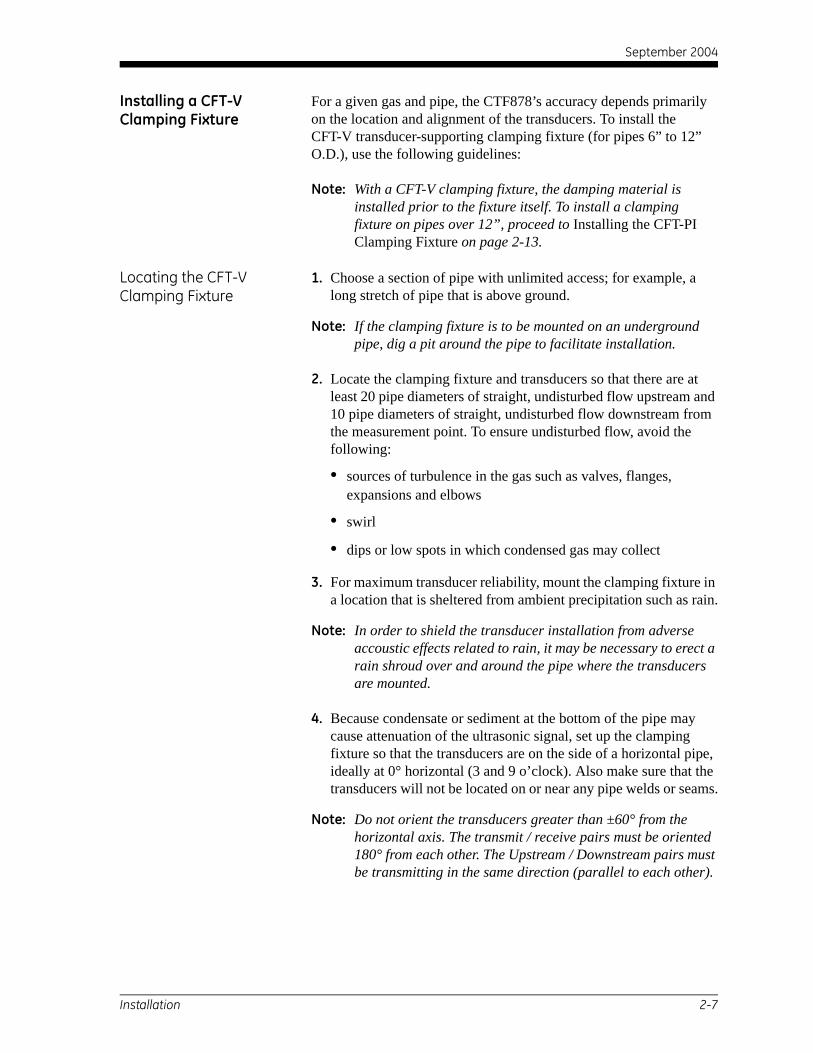
For a given gas and pipe, the CTF878’s accuracy depends primarily on the location and alignment of the transducers. To install the CFT-V transducer-supporting clamping fixture (for pipes 6” to 12” O.D.), use the following guidelines:
Note: With a CFT-V clamping fixture, the damping material is installed prior to the fixture itself. To install a clamping fixture on pipes over 12”, proceed to Installing the CFT-PI Clamping Fixture on page 2-13.
Locating the CFT-V Clamping Fixture
1. Choose a section of pipe with unlimited access; for example, a long stretch of pipe that is above ground.
Note: If the clamping fixture is to be mounted on an underground pipe, dig a pit around the pipe to facilitate installation.
2. Locate the clamping fixture and transducers so that there are at least 20 pipe diameters of straight, undisturbed flow upstream and 10 pipe diameters of straight, undisturbed flow downstream from the measurement point. To ensure undisturbed flow, avoid the following:
• sources of turbulence in the gas such as valves, flanges, expansions and elbows
• swirl
• dips or low spots in which condensed gas may collect
3. For maximum transducer reliability, mount the clamping fixture in a location that is sheltered from ambient precipitation such as rain.
Note: In order to shield the transducer installation from adverse accoustic effects related to rain, it may be necessary to erect a rain shroud over and around the pipe where the transducers are mounted.
4. Because condensate or sediment at the bottom of the pipe may cause attenuation of the ultrasonic signal, set up the clamping fixture so that the transducers are on the side of a horizontal pipe, ideally at 0° horizontal (3 and 9 o’clock). Also make sure that the transducers will not be located on or near any pipe welds or seams.
Note: Do not orient the transducers greater than ±60° from the horizontal axis. The transmit / receive pairs must be oriented 180° from each other. The Upstream / Downstream pairs must be transmitting in the same direction (parallel to each other).
Installation 2-7

September 2004
Preparing for CFT-V Clamping Fixture Installation
Before the CFT-V clamping fixture can be installed, the following procedures must be completed:
• the pipe surface sanded
• the transducer spacing and TAG path set
• the damping material applied to the pipe
• the yokes positioned on the fixture
Sanding the Pipe Using a grinding tool or sand paper, smooth out the sections of the pipe where the transducers will be installed. The best approach is to grind on both sides of the pipe an area the length of the clamping fixture and ± 60° from the plane where the transducers are intended to be installed. Grinding such a large area ensures that the transducers are installed on a smooth section after the pipe is covered with damping material.
Setting the Transducer Spacing and TAG path
The following procedure can be easily done before installing the clamping fixture on the pipe. For a more detailed description of these steps, refer to Programming Site Data on page 3-6:
1. Power up the CTF878 flowmeter.
2. In the top-level menu, enter Program / Transducer to select the transducers used.
3. Proceed to Program / Pipe to enter the pipe characteristics:material, outside diameter and wall thickness.
4. Enter Program / Fluid to select the fluid inside the pipe.
The flowmeter then calculates the transducer spacing and suggests the TAG path. The user then goes to Program / Path where these two parameters are available. The TAG path can be overwritten if the user wants to use a value other than the one suggested by the flowmeter.
IMPORTANT: The TAG path set on the clamping fixture HAS to be the one displayed under Program / Path when the instrument is operating, otherwise the velocity output will be incorrect.
2-8 Installation

September 2004
Applying DMP-1 Damping Material for a CFT-V Clamping Fixture
Note: If DMP-3 damping material is being used, refer to Applying DMP-3 Damping Material on page 2-19. If the pipe temperature is over 150°F, a PDJ pipe damping jacket with DMP-3 damping material is required (see Installing the PDJ Damping Jacket on page 2-21).
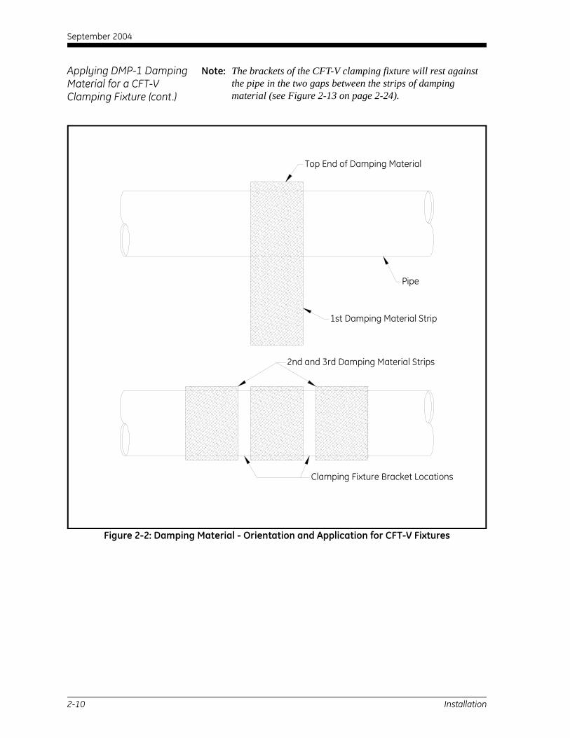
The surface of the pipe should be covered with damping material. Three pieces of the material should be placed as follows: one between the ends of the CFT-V clamping fixture and one on either side of the fixture. Use the following instructions and Figure 2-2 on page 2-10:
Note: The damping material pieces come cut to size as follows: Length = outside diameter of pipe X 3.25 Width = 15 inches for a CFT-V8 clamping fixture 19 inches for a CFT-V12 clamping fixture
1. Place the first piece of damping material at the flow velocity measurement section. Position the strip as shown in Figure 2-2.
2. Peel the protective layer of paper off the damping material from the top to approximately 3 inches down and apply the strip to the pipe, starting from the top.
Note: If too much of the paper layer is peeled off at one time, the damping material will be harder to handle and apply to the pipe without making air bubbles.
IMPORTANT: The damping material should adhere very tightly to the pipe.
3. Continue to peal off the paper and apply the damping material to the pipe 3 inches at a time. Pull on the strip during each application to assure a tight fit.
4. Before peeling off each new section of the paper layer, be sure the previously applied section of damping material adheres firmly to the pipe. Apply pressure to it with your hands, going from the previously applied to the newly applied section.
Note: The purpose of this operation is to avoid the presence of air bubbles between the damping material and the pipe.
When the user is done applying the damping material, there should be one layer of it around the pipe with a small overlap.
5. Visually inspect the pipe for the presence of air bubbles and wrinkles. Then apply pressure to any bubbles and wrinkles to eliminate them.
6. Repeat steps 2 through 5 to apply the two other strips of damping material on either side of the first, leaving about a two-inch gap between the strips.
Installation 2-9
September 2004
Applying DMP-1 Damping Material for a CFT-V Clamping Fixture (cont.)
Note: The brackets of the CFT-V clamping fixture will rest against the pipe in the two gaps between the strips of damping material (see Figure 2-13 on page 2-24).
Figure 2-2: Damping Material - Orientation and Application for CFT-V Fixtures
Pipe
1st Damping Material Strip
Top End of Damping Material
Clamping Fixture Bracket Locations
2nd and 3rd Damping Material Strips
2-10 Installation

September 2004
Positioning the Yokes The CFT-V clamping fixture yokes are usually set in place at the factory, based on the information given at the time of the order. If it becomes necessary to reposition the yokes, proceed as follows:
1. Referring to Figure 2-3 below, set the first yoke at a short distance from the end bracket and tighten the yoke screw.
2. Using calipers, set the opposite yoke at a distance S from the opposite bracket and tighten the yoke screws.
Note: Distance S is equal to the distance of the first yoke from the end bracket plus the transducer spacing (see Setting the Transducer Spacing and TAG path on page 2-7).
3. Set the TAG path one side at a time and tighten the yoke screws before repeating this step for the other side.
.
Figure 2-3: CFT-V Clamping Fixture Setup
TAG path
Transducer
Yoke Screw
Yoke
Slider
Bracket
ThreadedRod
Bracket
Nut
Parts are typical.
Clamping Fixture isshown from the top.
Rail
SpacingTAG path
S
R
Installation 2-11

September 2004
Mounting the CFT-V Clamping Fixture
Refer to Figure 2-3 on page 2-11 and mount the CFT-V clamping fixture on the pipe.
IMPORTANT: The measurement plane (the plane formed by the four transducers) should be horizontal or as close to horizontal as possible.
1. Place the clamping fixture on the pipe so that the brackets rest in the two gaps between the strips of damping material.
2. Thread the nuts on the ends of the threaded rods and lightly tighten them with a wrench.
3. Using a caliper, measure the four spacings (represented by R in Figure 2-3 on page 2-11) between the brackets and make sure that they are the same.
Note: To readjust the spacings between the brackets, work on one end of the fixture at a time.
4. If there is a need to readjust the spacings, loosen the nut on the smaller spacing rod, and tighten the nut on the bigger spacing rod.
5. Use the caliper again and check to see if the bottom and top spacings on one end are the same size.
6. After ensuring the gaps are the same size, repeat the process on the other end of the clamping fixture.
!WARNING!Proper grounding of the clamping fixture
(using the grounding lugs provided) is required,to prevent the possibility of electric shock and
to meet CE Mark compliance.
The CFT-V clamping fixture is now ready for transducer installation. Proceed to Installing Transducers on page 2-23.
2-12 Installation

September 2004
Installing a CFT-PI Clamping Fixture
For a given gas and pipe, the CTF878’s accuracy depends primarily on the location and alignment of the transducers. To install the CFT-PI clamping fixture (for pipes over 12” O.D.), use the following guidelines:
Note: A CFT-PI clamping fixture should be installed before the damping material is applied to the pipe. To install a clamping fixture on pipes between 6” and 12” O.D., see Installing the CFT-V Clamping Fixture on page 2-7.
Locating the CFT-PI Clamping Fixture
1. Choose a section of pipe with unlimited access; for example, a long stretch of pipe that is above ground.
Note: If the clamping fixture is to be mounted on an underground pipe, dig a pit around the pipe to facilitate installation.
2. Locate the clamping fixture and transducers so that there are at least 20 pipe diameters of straight, undisturbed flow upstream and 10 pipe diameters of straight, undisturbed flow downstream from the measurement point. To ensure undisturbed flow, avoid the following:
• sources of turbulence in the gas such as valves, flanges, expansions and elbows
• swirl
• dips or low spots in which condensed vapor or liquids may collect
3. For maximum transducer reliability, mount the fixture in a location that is sheltered from precipitation.
Note: In order to shield the transducer installation from adverse accoustic effects related to rain, it may be necessary to erect a rain shroud over and around the pipe where the transducers are mounted.
4. Because condensate or sediment at the bottom of the pipe may cause attenuation of the ultrasonic signal, set up the clamping fixture so that the transducers are on the side of a horizontal pipe, ideally at 0° horizontal (3 and 9 o’clock). Also make sure that the transducers will not be located on or near any pipe welds or seams.
Note: Do not orient the transducers greater than ±60° from the horizontal axis. The transmit / receive pairs must be oriented 180° from each other. The Upstream / Downstream pairs’ must be transmitting in the same direction (parallel to each other).
Installation 2-13

September 2004
Preparing for CFT-PI Clamping Fixture Installation
Before the clamps can be installed, the following procedures must be completed:
• the pipe surface sanded
• the transducer spacing and TAG path set
Sanding the Pipe Using a grinding tool or sand paper, smooth out the sections of the pipe where the transducers will be installed. The best approach is to grind on both sides of the pipe an area the length of the clamping fixture and ± 60° from the plane where the transducers are intended to be installed. Grinding such a large area ensures that the transducers are installed on a smooth section.
Setting the Transducer Spacing and TAG path
The following procedure can be easily done before installing the CFT-PI clamping fixture on the pipe. For a more detailed description of these steps, refer to Programming Site Data on page 3-6:
1. Power up the CTF878 flowmeter.
2. In the top-level menu, enter Program / Transducer to select the transducers used.
3. Proceed to Program / Pipe to enter the pipe characteristics:material, outside diameter and wall thickness.
4. Enter Program / Fluid to select the fluid inside the pipe.
The flowmeter then calculates the transducer spacing (S) and suggests the TAG path. The user then goes to Program / Path where these two parameters are available. The TAG path can be overwritten if the user wants to use a value other than the one suggested by the flowmeter.
IMPORTANT: The TAG path used to set up the CFT-PI clamping fixture HAS to be the one displayed under Program / Path when the instrument is operating, otherwise the velocity output will be incorrect.
2-14 Installation
September 2004
Mounting the CFT-PI Clamping Fixture
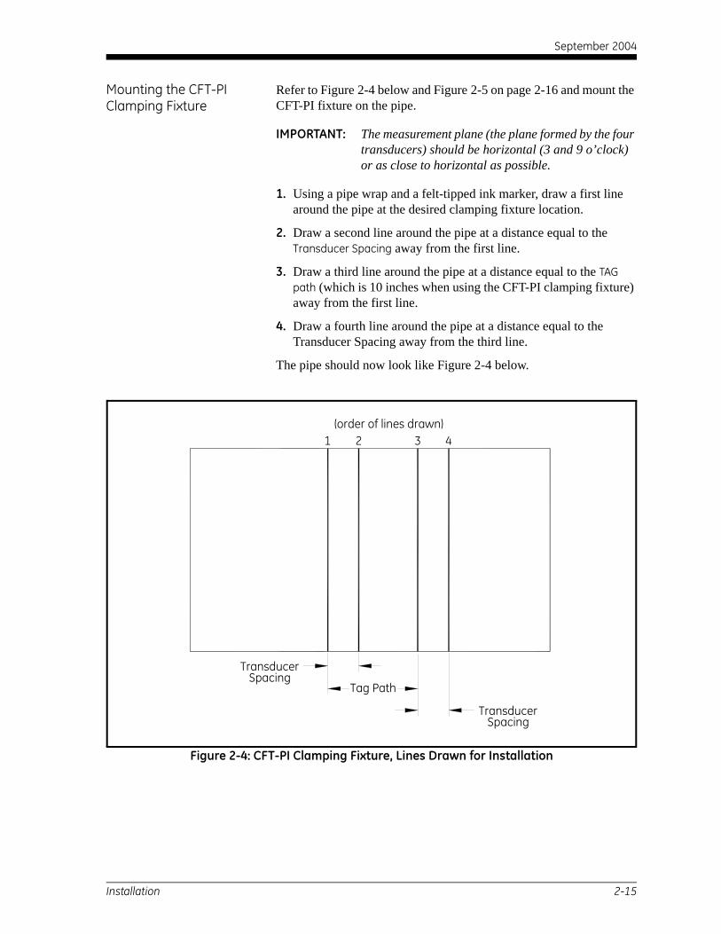
Refer to Figure 2-4 below and Figure 2-5 on page 2-16 and mount the CFT-PI fixture on the pipe.
IMPORTANT: The measurement plane (the plane formed by the four transducers) should be horizontal (3 and 9 o’clock) or as close to horizontal as possible.
1. Using a pipe wrap and a felt-tipped ink marker, draw a first line around the pipe at the desired clamping fixture location.
2. Draw a second line around the pipe at a distance equal to the Transducer Spacing away from the first line.
3. Draw a third line around the pipe at a distance equal to the TAG path (which is 10 inches when using the CFT-PI clamping fixture) away from the first line.
4. Draw a fourth line around the pipe at a distance equal to the Transducer Spacing away from the third line.
The pipe should now look like Figure 2-4 below.
Figure 2-4: CFT-PI Clamping Fixture, Lines Drawn for Installation
Tag Path
TransducerSpacing
TransducerSpacing
1 2 3 4(order of lines drawn)
Installation 2-15
September 2004
Mounting the CFT-PI Clamping Fixture (cont.)
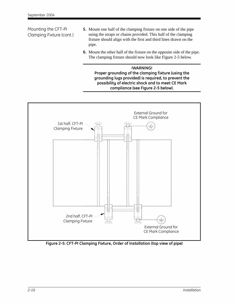
5. Mount one half of the clamping fixture on one side of the pipe using the straps or chains provided. This half of the clamping fixture should align with the first and third lines drawn on the pipe.
6. Mount the other half of the fixture on the opposite side of the pipe. The clamping fixture should now look like Figure 2-5 below.
!WARNING!Proper grounding of the clamping fixture (using the grounding lugs provided) is required, to prevent the
possibility of electric shock and to meet CE Mark compliance (see Figure 2-5 below).
Figure 2-5: CFT-PI Clamping Fixture, Order of Installation (top view of pipe)
2nd half, CFT-PIClamping Fixture
1st half, CFT-PIClamping Fixture
External Ground forCE Mark Compliance
CE Mark ComplianceExternal Ground for
2-16 Installation

September 2004
Applying DMP-1 Damping Material for a CFT-PI Clamping Fixture
Note: If DMP-3 damping material is being used, refer to Applying DMP-3 Damping Material on page 2-19. If the pipe temperature is over 150°F, a PDJ pipe damping jacket with DMP-3 damping material is required (see Installing the PDJ Damping Jacket on page 2-21).
The surface of the pipe should be covered with damping material. The three pieces of material should be placed as follows: one at each end of the fixture, and the third, cut into smaller pieces, and positioned between the straps or chains supporting the fixture. Use the following instructions and Figure 2-6 on page 2-18 as a guide:
Note: The damping material pieces come cut to size as follows: Length = outside diameter of pipe X 3.25 Width = 10”
1. Place the first piece of damping material on one side of the fixture. Position the piece in the same way as the first damping material strip shown in Figure 2-2 on page 2-10.
2. Peel the protective layer of paper off the damping material from the top to approximately 3 inches down and apply the strip to the pipe, starting from the top.
Note: If too much of the paper layer is peeled off at one time, the damping material will be harder to handle and apply to the pipe without making air bubbles.
IMPORTANT: The damping material should adhere very tightly to the pipe.
3. Continue to peal off the paper and apply the damping material to the pipe 3 inches at a time. Pull on the strip during each application to assure a tight fit.
4. Before peeling off each new section of the paper layer, be sure the previously applied section of damping material adheres firmly to the pipe. Apply pressure to it with your hands, going from the previously applied to the newly applied section.
Note: The purpose of this operation is to avoid the presence of air bubbles between the damping material and the pipe.
When the user is done applying the damping material, there should be one layer of it around the pipe with a small overlap.
5. Visually inspect the pipe for the presence of air bubbles and wrinkles. Then apply pressure to any bubbles and wrinkles to eliminate them.
6. Repeat steps 1 through 5 for the second piece of damping material at the opposite end of the fixture.
Installation 2-17

September 2004
Applying DMP-1 Damping Material for a CFT-PI Clamping Fixture (cont.)
7. Cut the third large piece of damping material into strips to fit between the two inside clamps (on opposite sides of the pipe) and between the straps or chains used to mount the clamps (see Figure 2-6 below).
8. Repeat steps 2 through 5 to apply each of the strips.
The CFT-PI clamping fixture is now ready for transducer installation. Proceed to Installing Transducers on page 2-23.
Figure 2-6: Locating Damping Material with a CFT-PI Clamping Fixture Installed
TOP VIEW
SIDE VIEW
CFT-PI CLAMPING FIXTURE
DAMPING MATERIAL
2-18 Installation

September 2004
Applying DMP-3 Damping Material
For some applications, particularly on higher-temperature pipes, DMP-3 compound should be used.
Note: If the pipe temperature is over 150°F, a PDJ pipe damping jacket with DMP-3 damping material applied is required (see Installing the PDJ Damping Jacket on page 2-21).
Preparing the Pipe To prepare the pipe for DMP-3 application:
1. Remove any loose paint or rust from the pipe surface with a file or emery cloth. If the finish is mirror-smooth, roughen the surface.
2. Mark the pipe to indicate the location of the clamping fixture and transducers (as in the previous sections, depending on the type of fixture being used).
3. While wearing appropriate gloves, degrease the pipe surface.
Applying the DMP-3 4. Place a piece of the DMP-3 material on top of the pipe, and use the palm of the hand to press it onto the pipe (see Figure 2-7 below).
Figure 2-7: Applying DMP-3 Damping Material
5. Spread the DMP-3 material so that it covers the whole area under the fixture, and 4 to 6 inches on both sides of the fixture, to a thickness of about 0.25 in. (6.4 mm), as shown in Figure 2-8 and Figure 2-9 on page 2-20.
Installation 2-19

September 2004
Applying DMP-3 Damping Material (cont.)
Figure 2-8: Spreading DMP-3 Damping Material
Installing the Clamping Fixture
6. Position the transducer yokes to the correct spacing and install the fixture around, but not on, the DMP-3 material.
7. Remove the DMP-3 material from the transducer locations (see Figure 2-9 below) and proceed to Installing Transducers on page 2-23.
Figure 2-9: DMP-3 Damping Material with Fixture Installed
2-20 Installation

September 2004
Installing the PDJ Pipe Damping Jacket
If the pipe temperature is over 150°F, you must use a pipe damping jacket with preapplied DMP-3. The jacket is available in standard pipe sizes (see Table 2-2 and Figure 2-10 below) or in other sizes on special order.
Figure 2-10: PDJ Pipe Damping Jacket (Dwg. #583-145)
Table 2-2: PDJ Pipe Damping Jacket - Standard Options*
Pipe Diameter PDJ Part Number
6” (152mm) 583-145-06
8” (203mm) 583-145-08
10” (254mm) 583-145-10
12” (305mm) 583-145-12
*If a pipe damping jacket other than those listed above is required, contact the factory for a special order.
TRANSDUCERWINDOW4 places
DAMPING MATERIAL
MOUNTING BRACKET
Installation 2-21

September 2004
Installing the PDJ Pipe Damping Jacket (cont.)
1. Remove any insulation from the installation area, as well as any loose paint, rust and high spots from the pipe.
2. Remove the backing paper from the inside of the pipe damping jacket (shown in Figure 2-11 below).
Figure 2-11: Pipe Damping Jacket (cutouts not shown)
3. Install the jacket on the pipe as shown in Figure 2-12 below. Align the cutouts with the previously marked transducer locations. Then tighten the clamping screws until some fluid drips from the bottom of the jacket.
!WARNING!The pipe and the dripping fluid will cause severe burns
upon contact with bare skin. Also, be sure not to inhale the fumes generated during the DMP-3 curing cycle.
As the damping material dries (over several hours), its effectiveness increases. Proceed to Installing Transducers on page 2-23.
Figure 2-12: Pipe Damping Jacket Installed
2-22 Installation

September 2004
Installing Transducers For a given gas and pipe, the CTF878’s accuracy depends primarily on the location and alignment of the transducers. Now that the clamping fixture is in place, use the following guidelines to install the four transducers. For detailed instructions on installing clamp-on transducers, refer to the supplied drawings and the GE Infrastructure Sensing Gas Transducer Installation Guide. For CFT-V clamping fixtures, follow the steps below. For CFT-PI clamping fixtures, proceed to Mounting Transducers on page 2-24.
Preparing for Installation with a CFT-V Clamping Fixture
Before the transducers can be mounted on the pipe to transmit and receive signals effectively, a hole must be cut in the damping material at each transducer location. To complete this important step, proceed as follows:
1. Place a transducer in one of the sliders and tighten it down until it rests flat on the damping material.
2. Using a felt-tipped ink marker, draw the contour of the transducer's footprint on the damping material.
3. Remove the transducer from the slider and repeat steps 1 and 2 at the three other slider positions.
4. Using a knife or a box cutter, cut holes in the damping material along the contour lines of each transducer footprint.
IMPORTANT: The holes cut along the transducers' contour lines must be big enough to allow the entire footprint of each transducer to sit on the pipewall without any interference from the damping material.
Note: This task may be difficult to complete because the yokes are partially in the way. If necessary, loosen the yoke screws and move the yokes.
5. Using a solvent consistent with safety, disposal and cleaning requirements, clean the four areas of pipewall visible through the four holes in the damping material. Make sure there are no residues of damping material on these areas.
Note: If the faces of the transducers are not free of residues, clean them using the same solvent.
6. If you moved the yokes in step 4, remember to put them back to their exact positions before tightening the yoke screws.
IMPORTANT: You must use the caliper again to ensure that the transducer spacing and TAG path are correctly set.
Installation 2-23

September 2004
Mounting Transducers Prepare the transducers for mounting as follows:
1. Dispense a bead of CPL-16 couplant on the face of one transducer.
2. Take another transducer and rub the two transducer faces against one another so that the couplant spreads out on the entire face of each transducer.
Note: The size of the bead of couplant dispensed on the first transducer should be enough, that in the end, there is a thin homogeneous coat of couplant on the faces of both transducers.
3. Repeat these steps with the two remaining transducers.
If a CFT-V clamping fixture is being used, refer to Figure 2-13 below for transducer orientation and complete the following steps one transducer at a time. If a CFT-PI clamping fixture is installed, refer to Figure 2-6 on page 2-18 for transducer orientation and complete the following steps one transducer at a time.
Figure 2-13: Typical CFT-V Clamping Fixture / Transducer Setup (top view of pipe)
UPSTREAM
UPSTREAMDOWNSTREAM
DOWNSTREAM
CLAMPINGFIXTURE
FLOW
TAG PATH
TRANSDUCER
SPACING
EXTERNAL GROUNDFOR CE MARK COMPLIANCE
RECEIVER
TRANSMITTERTRANSMITTER
RECEIVER
2-24 Installation

September 2004
Mounting Transducers (cont.)
4. Carefully position the transducer inside the clamping fixture's slider.
Note: While doing this, make sure that none of the couplant gets wiped off of the transducer's face. The best way to prevent this is to hold the transducer by the stem and keep its face parallel to the pipe wall at all times.
5. While holding the transducer against the back of the slider and parallel to the pipe wall, tighten it down until it is in contact with the pipe wall.
6. Apply a finger-tight torque until the transducer stops moving inside the slider.
Caution!If excessive torque is applied, the face of the transducer
may be damaged.
7. Repeat steps 4 through 6 for the remaining three transducers.
Figure 2-14: CFT-V Clamping Fixture with Transducers and Conduit Boxes Installed
Installation 2-25

September 2004
Wiring the Transducers The user must know the direction of the flow since it will dictate how to connect the transducers to the flowmeter (refer to Figure 2-17 on page 2-29 for transducer wiring).
Identifying the Transducers
The transducers must be connected so that the flow direction is from the Upstream pair of transducers to the Downstream pair of transducers. A pair of transducers is made up of a Receiver and a Transmitter (see Figure 2-13 on page 2-24 for a CFT-V fixture installation or Figure 2-6 on page 2-18 for a CFT-PI installation).
In a pair of transducers, the Transmitter must be downstream of the Receiver. Basically, along the axis of the pipe, the Transmitter sends a signal opposite the direction of the flow.
Making Cable Connections GE Infrastructure Sensing supplies transducer cables up to 500 ft (153 m) in length. If longer cables are required, consult the factory for assistance.
When installing the transducer cables, always observe established standard practices for the installation of electrical cables. Specifically, do not route transducer cables alongside high-amperage AC power lines or any other cables that could cause electrical interference. Also, protect the transducer cables and connections from the weather and corrosive atmospheres.
Note: If non-GE Infrastructure Sensing cables are being used to connect the flowmeter transducers to the CTF878 electronics console, they must have electrical characteristics identical to the GE Infrastructure Sensing cables. Type RG 62 a/u coaxial cable should be used, and each cable must be the same length (within ±4 in.).
Figure 1-1 on page 1-4 shows a typical CTF878 system. For detailed instructions on installing clamp-on transducers, refer to the supplied drawings and the GE Infrastructure Sensing Gas Transducer Installation Guide.
!WARNING!Proper grounding of the clamping fixture
(using the grounding lugs provided) is required,to prevent the possibility of electric shock
and to meet CE Mark compliance.
2-26 Installation

September 2004
Wiring the Transducers (cont.)
Wiring a typical CTF878 ultrasonic gas flowmeter system requires interconnection of the following components:
• four transducers (two upstream and two downstream)
• two preamplifiers (one for the upstream receiver and one for the downstream receiver)
• the electronics console
IMPORTANT: For the flowmeter system to function correctly, the CTF878 receiver board frequency range must match that of the transducers being used. To check, compare the labels on the electronics console and on the transducers. Default frequency ranges include: 1MHz / 888kHz, 500kHz / 471kHz, 250kHz / 222kHz
Refer to Figure 2-17 on page 2-29 and complete the following steps:
!WARNING!Before connecting the transducers, take them to a safe area and discharge any static buildup by shorting the
center conductor of the transducer cables to the metal shield on the cable connector.
1. Using a pair of coaxial cables with BNC to BNC connectors (supplied by the factory or equivalent), connect the two transmitter transducers to connectors TX1 (Upstream Transmitter) and TX2 (Downstream Transmitter) in the electronics console (see Figure 2-16 on page 2-28).
Caution!As part of maintaining the FM/CSA environmental rating
(NEMA/TYPE 4) on the remote preamplifier, thread sealant is required on all conduit entries.
2. Using a second pair of BNC to BNC coaxial cables, connect the preamplifiers (attached to the receiver transducers) to RX1 (Upstream Receiver) and RX2 (Downstream Receiver) in the electronics console (see Figure 2-15 and Figure 2-16 on page 2-28).
After the wiring has been completed, the transducer channels must be programmed before measurements can begin. See Chapter 3, Initial Setup, for instructions.
Installation 2-27

September 2004
Wiring the Transducers (cont.)
Figure 2-15: Receive Transducer with Preamplifier
Figure 2-16: Transducer Connections - Main PC Board
UpstreamTransmitter
TX1
DownstreamTransmitter
TX2
UpstreamReceiver
RX1
DownstreamReceiver
RX2
2-28 Installation

September 2004
Figure 2-17: CTF878 - Transducer Wiring
FLO
WSRCDX
TX2
RX2
DN
STRE
AM
TX1
RX1
STRE
AMU
P
FLO
WU
P STR
EAM
DO
WN
STRE
AM
ORN
R ED
GRN
BLU
TRAN
SMIT
TRA N
SDU
CER
PREA
MPL
IFIE
R
PREA
MPL
IFIE
R
E LEC
TRO
NIC
SCO
NSO
LECO
NN
ECTI
ON
S
CAU
T IO
N!
A s p
art o
f mai
n tai
ning
the
FM/ C
SA e
n viro
nme n
tal r
a tin
g (N
EMA/
TYPE
4),
thre
ad s
eala
nt is
r equ
ired
on a
ll c o
ndui
t ent
ries.
CTF8
7 8
TRAN
SMIT
TRA N
SDU
CER
R
E CEI
VETR
A NSD
UCE
RRE
CEIV
ETR
A NSD
UCE
R
Installation 2-29

September 2004
Installing Temperature and Pressure Transmitters
Temperature and pressure transmitters are usually not required with the CTF878 system, but may be installed for standard volumetric or mass flow determination.
IMPORTANT: Under changing temperature and pressure conditions, the CTF878 can calculate standard volumetric flow accurately only if temperature and pressure transmitters have been installed.
Locating Temperature and pressure transmitters should be positioned downstream of the clamp-on fixture / transducers, no closer than two pipe diameters and no further away than twenty pipe diameters.
Mounting Typically, a 1/2” NPT female threaded port is used to mount the transmitters on the pipe. If the pipeline is insulated, the coupling may need to be extended to provide convenient access. Of course, other types of mounting ports, including flanged ports, may be used for the transmitters.
Figure 2-18 below shows a typical mounting arrangement for the pressure and temperature transmitters. The temperature sensor should protrude 1/4 to 1/2 way into the pipe.
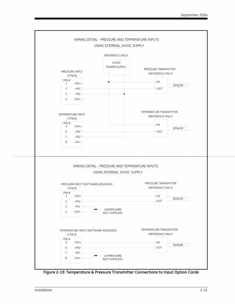
Wiring These transmitters must use a 0/4-20 mA signal to transmit the temperature and pressure values to the CTF878 electronics console. In turn, the electronics console will provide a 24 VDC signal to power the transmitters. Any transmitters or sensors that are used must have an accuracy equal to 0.5% of the reading or better.
Note: Resistive Thermal Devices (RTDs) are a good choice for measuring the temperature.
To wire the transmitters, refer to Figure 2-19 on page 2-31.
Figure 2-18: Typical Temperature/Pressure Transmitter Mounting
Temperature Transmitter
RTD
Thermowell
Coupling
Isolation Valve
Flowcell Wall
PressureTransmitter
2-30 Installation
September 2004
Figure 2-19: Temperature & Pressure Transmitter Connections to Input Option Cards
PIN #24V+
+IN1
-IN1
24V-
1
2
3
4
PRESSURE INPUT (SOFTWARE ASSIGNED)CTF878
TEMPERATURE INPUT (SOFTWARE ASSIGNED)CTF878
PIN #5
6
7
8 24V-
-IN2
+IN2
24V+
TEMPERATURE TRANSMITTER
-OUT
(REFERENCE ONLY)
+IN
-OUT
+IN
(REFERENCE ONLY)PRESSURE TRANSMITTER
SENSOR
SENSOR
PIN #24V+
+IN1
–IN1
24V–
1
2
3
4
PRESSURE INPUTCTF878
PIN #5
6
7
8 24V–
–IN2
+IN2
24V+
TEMPERATURE TRANSMITTER
–OUT
(REFERENCE ONLY)
+IN
–OUT
+IN
(REFERENCE ONLY)PRESSURE TRANSMITTER
SENSOR
SENSOR
24VDCPOWER SUPPLY
(REFERENCE ONLY)
USING EXTERNAL 24VDC SUPPLY
WIRING DETAIL - PRESSURE AND TEMPERATURE INPUTS
USING INTERNAL 24VDC SUPPLY
WIRING DETAIL - PRESSURE AND TEMPERATURE INPUTS
TEMPERATURE INPUTCTF878
JUMPER WIRE(NOT SUPPLIED)
(NOT SUPPLIED)JUMPER WIRE
Installation 2-31

September 2004
PC Board Connections
Wiring the 0/4-20 mA Analog Outputs
The standard configuration of the CTF878 flowmeter includes two isolated 0/4-20 mA analog outputs (designated as 1 and 2). Connections to these outputs may be made with standard twisted-pair wiring. The current loop impedance for these circuits must not exceed 550 ohms. Refer to Figure 2-24 on page 2-39 for the location of the Analog Output terminal block and wire the terminal block as shown.
Wiring the Serial Port The CTF878 is equipped with a built-in serial communications port. The standard port is an RS232 interface, but an optional RS485 interface is available upon request. Proceed to the appropriate sub-section for wiring instructions. For more information on serial communications, refer to the EIA-RS Serial Communications Manual (916-054).
Wiring the RS232 Interface The RS232 serial communications port may be used for connecting the CTF878 flowmeter to a personal computer. The RS232 serial interface is wired as Data Terminal Equipment (DTE), and the signals available at the flowmeter’s RS232 Serial Port terminal block are shown in Table 2-3 below. Refer to Figure 2-24 on page 2-39 to locate terminal block RS232 and complete the following steps to wire the terminal:
1. Use the information in Table 2-3 below to construct a suitable cable for connecting the CTF878 to the external device. If desired, an appropriate cable may be purchased from the factory.
2. Disconnect the main power to the unit and open the cover on the electronics enclosure. Remove the plastic shroud to access the serial communication connector.
3. Wire the flying leads end of the cable to terminal block RS232 and connect the other end of the cable to the printer, ANSI terminal or personal computer.
Table 2-3: RS232 Connections to a PC (DCE Device)
RS232Pin #
SignalDescription
DCE DB9Pin #
1 RTN (Return) 5
2 TX (Transmit) 2
3 RX (Receive) 3
4 DTR (Data Terminal Ready) 4
5 CTS (Clear to Send) 7
2-32 Installation

September 2004
Wiring the RS232 Interface (cont.)
4. Replace the plastic shroud, close the cover on the electronics enclosure and reconnect the main power to the unit.
5. Before initializing communication between the CTF878 and the personal computer, enter the Meter/Communications option and ensure that the CTF Communications settings match the settings of the personal computer.
Wiring the RS485 Interface Use the optional RS485 serial port to network multiple CTF878 flowmeters to a single computer terminal.
To wire the RS485 serial port, complete the following steps:
1. Disconnect the main power to the unit and open the cover on the electronics enclosure. Remove the plastic shroud to access the serial communication connector.
2. Use the information in below to connect the CTF878 to the personal computer.
3. After the wiring has been completed, replace the plastic shroud, close the cover on the electronics enclosure and reconnect the main power to the unit.
Table 2-4: RS485 Connections
RS232 Pin # Signal Description1 Shield
2 Transmit Data (RS485+)
3 Receive Data (RS485–)
Installation 2-33

September 2004
Option Card Wiring
Wiring an Alarms Option Card
The CTF878 flowmeter can accommodate up to 4 alarm option cards. Each alarms option card includes three Form C relays (designated as A, B and C).
The alarm relays on the option card are available in two types:
• general purpose
• hermetically sealed for Class I, Division 2 hazardous areas.
The maximum electrical ratings for the relays are listed in Chapter 4, Specifications. Each of the three alarm relays can be wired either as Normally Open (NO) or Normally Closed (NC).
In setting up an alarm relay, it may be wired for either conventional or fail-safe operation. In fail-safe mode, the alarm relay is constantly energized, except when it is triggered by a power failure or other interruption. See Figure 2-20 below for the operation of a NO alarm relay in both conventional and fail-safe mode.
Connect the two wires required for each alarm relay in accordance with the pin number assignments shown in Figure 2-24 on page 2-39.
Figure 2-20: Conventional and Fail-Safe Operation
Conventionalnot triggered
NO
C
NC
not triggeredFail-Safe
NO
C
NC
ALARMMONITORING
DEVICE DEVICEMONITORING
ALARM
triggeredConventional
NO
C
NC NC
C
NO
ALARMMONITORING
DEVICEDEVICEMONITORING
ALARM
or power failureFail-Safe triggered
2-34 Installation

September 2004
Wiring a 0/4-20 mA Analog Inputs Option Card
To calculate the standard volumetric flow rate of natural gas, the CTF878 requires accurate temperature and pressure data from the measurement site. Transmitters installed on the pipe can provide this information via an optional 0/4-20 mA analog inputs card. This option card includes two isolated 0/4-20 mA analog inputs (designated as A and B), each of which includes a 24 VDC power supply for loop-powered transmitters. Either input may be used to process the temperature signal, while the other input is used to process the pressure signal.
Note: To enter programming data during operation of the meter, it will be necessary to know which input is assigned to which process parameter. This information should have been entered in Appendix B, Data Records.
The analog inputs, which have an impedance of 118 ohms, should be connected with standard twisted-pair wiring. Power to the transmitters may be supplied either by the integral 24 VDC power supply on the analog input card or by an external power supply. Figure 2-21 below shows typical wiring diagrams, with and without an external power supply, for one of the analog inputs.
Figure 2-21: Analog Input Wiring Diagram
PIN #(RTN)
(INLO)
(INHI)
(+24V)
4
3
2
1
Analog Input
– OUT
+ IN
Transmitter
SENSOR
24VDCPOWER SUPPLY
With External Power Supply
With Internal Power Supply
Analog Input
2
1
3
4PIN #
(+24V)
(INLO)
(INHI)
(RTN) Transmitter
+ IN
– OUTSENSOR
Jumper
Installation 2-35

September 2004
Wiring a 0/4-20 mA Analog Inputs Option Card (cont.)
Wire the analog input terminal block in accordance with the pin number assignments shown in Figure 2-24 on page 2-39.
If the flowmeter system includes additional transmitters, the CTF878 can accommodate up to three more analog inputs option cards. These option cards are identical to the temperature/pressure card described above and they should be wired in the same manner (see Figure 2-21 on page 2-35).
The analog inputs on the option card(s) can be calibrated with the CTF878’s built-in analog outputs. However, be certain that the analog outputs have been calibrated first. See Chapter 1, Calibration, in the Service Manual for the appropriate procedures.
Wiring a Totalizer/Frequency Outputs Option Card
The CTF878 can accommodate up to four totalizer/frequency outputs option cards. Each totalizer/frequency outputs option card provides four outputs (designated as A, B, C, and D) that can be used as either totalizer or frequency outputs.
Each totalizer/frequency output requires two wires. Wire this terminal block in accordance with the pin number assignments shown in Figure 2-24 on page 2-39. Figure 2-22 below shows sample wiring diagrams of a totalizer output circuit and a frequency output circuit.
Figure 2-22: Totalizer/Frequency Outputs Wiring
Model CTF878
Totalizer Output
Pulse CounterMax. Current: 4 AmpsMax. Voltage: 150 Volts
Isolation Voltage: 500 VoltsMax. Load Power: 1.0 Watt In
NOC
C = Isolated Return
Volts +(Int. Pwr Sup.)
Load
Volts –(Common)
Frequency CounterModel CTF878
NOC
C = Isolated Return
Frequency Output
+5V
200
INCommon
2-36 Installation

September 2004
Wiring an RTD Inputs Option Card
The CTF878 can accommodate up to four RTD (Resistance Temperature Device) inputs option cards. Each RTD inputs option card provides two direct RTD inputs (designated as A and B).
Each RTD input requires three wires, which should be fed through one of the conduit holes on the bottom of the electronic console. Wire this terminal block in accordance with the pin number assignments shown in Figure 2-24 on page 2-39.
Wiring a 0/4-20 mA Analog Outputs Option Card
The CTF878 flowmeter can accommodate up to 4 analog outputs option cards. Each analog outputs option card includes four isolated 0/4-20 mA outputs (designated as A, B, C and D).
Connections to these outputs may be made with standard twisted-pair wiring. The total current loop impedance for these circuits must not exceed 1,000 ohms. Wire this terminal block in accordance with the pin number assignments shown in Figure 2-24 on page 2-39.
Once the CTF878 system is completely wired, proceed to Chapter 3, Initial Setup, to configure the unit for operation.
Installation 2-37

September 2004
2-38
Figu
re 2
-23:
CTF
878
NEM
A 4X
Enc
losu
re -
Out
line
and
Mou
ntin
g (D
wg.
#71
2-11
86)
VIEW A-A
Plate for 3/4" (19) Conduit
VIEW A-A
Plate for 1/2" (13) Conduit reference.
inches (millimeters).
1.20(30)Typ.
2 (62)
Ø1.10 (28), 6 places
Ø.88 (22), 10 places
1.50(38)Typ.
2 (62)
Installation
AA
Notes:
1. All dimensions are
2. Dimensions are in
ENTERMENU
?ESC
SEL
.7
4
1
0
8
5
2
9
6
3
F1 F2 F3
CTF878 Flowmeter
11.46 (291)
14.24(362)
13.48(342)
2.4
5.08(129)Typ.
1.30(33)
1.75(44)
2.4
1.54(39)
1.63(41)
8.00 (203)Ø.31 (10)
0.38 (10)
1.51 (38) 4 places

September 2004
2-39
Figu
re 2
-24:
CTF
878
Elec
tron
ics
Cons
ole
Wir
ing
(Dw
g. #
702-
508)
SLOT2 SLOT1
M
C
A
B
CNO D
TOTL/FREQ
CNO
NOC
NOC
COM
COM
+COM
+COM
C
B
RTD IN
UPTX1
RX1
XDCRS
STREAM
RX2
TX2STREAMDN
ANALOG OUT
1 1
8 8
14
1 RCV3 TWIND5 RWIND7 GATE9 ARTN11 RI_PK13 R1_I15 R1_Q
2 ARTN4 –6 DRTN8 DRTN10 ARTN12 R2_PK14 R2_I16 R2_Q
2P1 1
1615
DIRECT RTD INPUTS
1 Input A - SIG(+)
Input A - Common (C)2
3
N/C4
5
6
7
8
DescriptionPin #
Input A - Common (C)
Input B - Common (C)
Input B - SIG(+)
N/C
Input B - Common (C)
EQUENCY OUTPUTS
A - Common (C)
A - Normally Open (NO)
Description
B - Common (C)
B - Normally Open (NO)
C - Common (C)
C - Normally Open (NO)
D - Common (C)
D - Normally Open (NO)
4-20 mA ANALOG OUTPUTS
DescriptionPin #
Output 1 - SIG1
Output 2 - RTN4
2 Output 1 - RTN
3 Output 2 - SIG
For CE compliance, the enclosure must be grounded. The grounding point is any one of the four mounting holes.
Downstream Receive Transducer
Upstream Receive Transducer
Downstream Transmit Transducer
Upstream Transmit Transducer
Plastic LVD Shroud
One option card of each available type is shown in this diagram. These cards are not always installed in the same slots used for this example.
Installation
WARNINGDISCONNECT POWER BEFORE
REMOVING FUSE.
SLOT6 SLOT5 SLOT4 SLOT3
CONNECTION DIAGRA
ALARMS
RTNSIG D
CSIGRTN
BSIGRTN
ASIGRTN
ANALOG IN
INHI
AINLOINHI+24V
RTN+24V
BINLORTN
G N L
100-240 VACFUSE
1 AMP RS232CTS R
DT
RX
TX
N
RT
TB1
5 1
1 1
8 8
TOTALIZER/FR
Output
Output
1
2
8
5
4
3
6
7
Pin #
Output
Output
Output
Output
Output
Output
4-20 mA ANALOG INPUTS
Input B - +24V
1
2
3
4
5
6
7
8
Pin # Description
Input B - INHI
Input B - INLO
Input B - RTN
Input A - +24V
Input A - INHI
Input A - INLO
Input A - RTN
4-20 mA ANALOG OUTPUTS
1
2
8
5
4
3
6
7
Pin # Description
Output A - RTN(–)
Output A - SIG(+)
Output B - RTN(–)
Output B - SIG(+)
Output C - SIG(+)
Output C - RTN(–)
Output D - SIG(+)
Output D - RTN(–)
Relay A - Normally Open (NO)1
2
8
5
4
3
6
7
9
Pin #
ALARM RELAYS
Description
Relay A - Common (C)
Relay A - Normally Closed (NC)
Relay B - Normally Open (NO)
Relay B - Common (C)
Relay B - Normally Closed (NC)
Relay C - Normally Open (NO)
Relay C - Common (C)
Relay C - Normally Closed (NC)
For compliance with the European Union's Low Voltage Directive (73/23/EEC), this unit requires an external power disconnect device such as a switch or circuit breaker. The disconnect device must be marked as such, clearly visible, directly accessible, and located within 1.8 m (6 ft) of the CTF878.
For compliance with the European Union's Low Voltage Directive (73/23/EEC), a transparent plastic shroud is required to protect the electrical connections. The shroud must remain in place, except while the unit is being wired, and reinstalled after the wiring has been completed.
RTN - Digital Return1
3
2
5
4
Description
RS232 SERIAL PORT
Pin #
TX - Transmit
RX - Receive
DTR - Data Terminal Ready
CTS - Clear To Send
Line Neutral
Line Power
DescriptionPin #
L
N
POWER INPUT External GroundConnection
1
9
A
B
C
C
CNO
NCNO
NONC
CNC
L N

Chapter 3

Initial Setup
Introduction. . . . . . . . . . . . . . . . . . . . . . . . . . . . . . . . . . . . . . . . . . . . . . . . . . . . 3-1
Powering Up . . . . . . . . . . . . . . . . . . . . . . . . . . . . . . . . . . . . . . . . . . . . . . . . . . . 3-1
Using the Screen. . . . . . . . . . . . . . . . . . . . . . . . . . . . . . . . . . . . . . . . . . . . . . . . 3-2
Using the Keypad . . . . . . . . . . . . . . . . . . . . . . . . . . . . . . . . . . . . . . . . . . . . . . . 3-4
Programming Site Data . . . . . . . . . . . . . . . . . . . . . . . . . . . . . . . . . . . . . . . . . 3-6
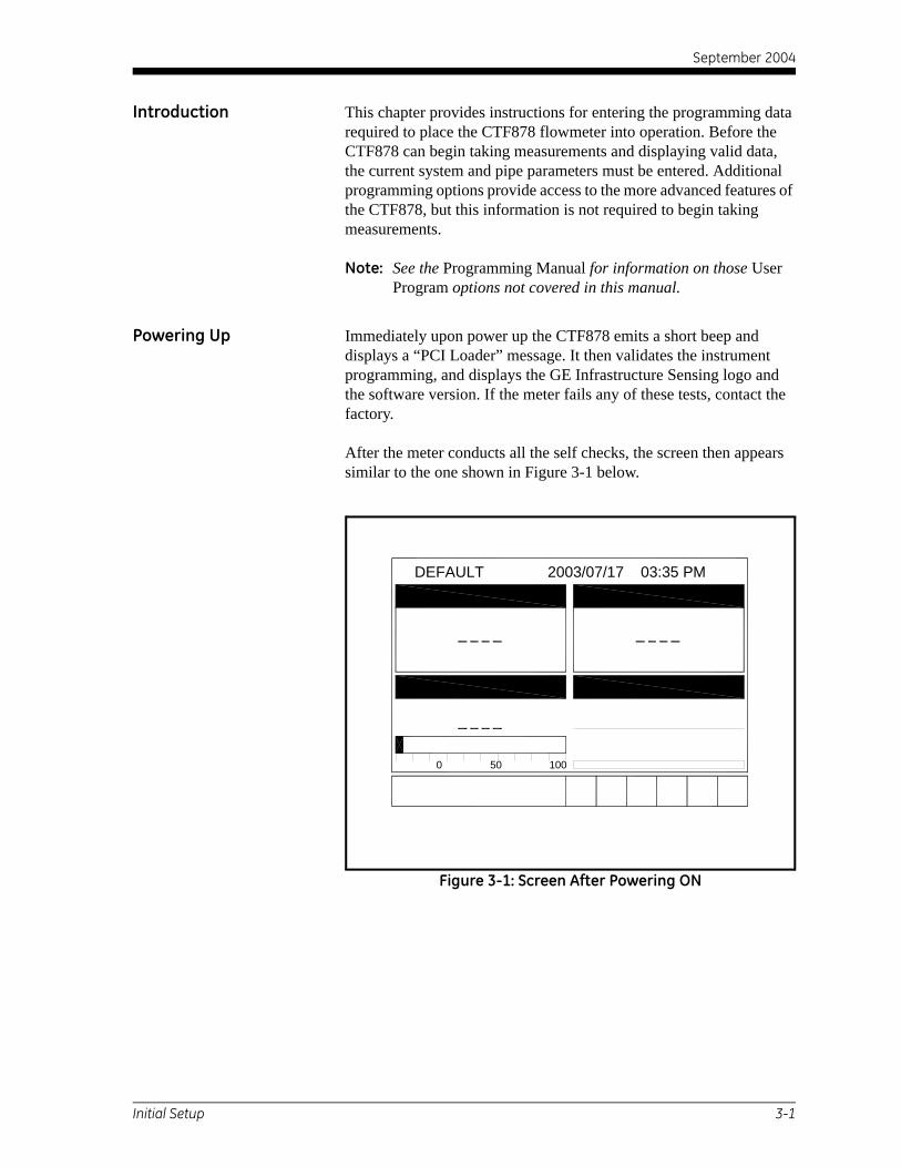
September 2004
Introduction This chapter provides instructions for entering the programming data required to place the CTF878 flowmeter into operation. Before the CTF878 can begin taking measurements and displaying valid data, the current system and pipe parameters must be entered. Additional programming options provide access to the more advanced features of the CTF878, but this information is not required to begin taking measurements.
Note: See the Programming Manual for information on those User Program options not covered in this manual.
Powering Up Immediately upon power up the CTF878 emits a short beep and displays a “PCI Loader” message. It then validates the instrument programming, and displays the GE Infrastructure Sensing logo and the software version. If the meter fails any of these tests, contact the factory.
After the meter conducts all the self checks, the screen then appears similar to the one shown in Figure 3-1 below.
Figure 3-1: Screen After Powering ON
0 50 100
DEFAULT 2003/07/17 03:35 PM
Initial Setup 3-1

September 2004
Using the Screen The essential features for operating the CTF878 are the screen and keypad. Although these features are common, the CTF878 design offers particular features to simplify and speed operation. The new menu system is very user-friendly; program information is now located on tabbed forms instead of on a long, linear menu.
The primary function of the screen is to display information in order for you to accurately and easily take measurements. The CTF878 screen consists of those parts shown in Figure 3-2 below.
Figure 3-2: CTF878 Screen in Operate Mode
The top line of the screen is the status bar, which normally displays the time and date. However, when you press [MENU] (the menu key), the menu bar replaces the status line.
The middle of the screen is the work area, which displays the measured parameters, numeric measurements, and both bar and line graphs. When you enter a selection on the menu bar (see Programming Site Data on page 3-6), this area displays menu prompts. A line at the bottom of the area also displays error code messages, which are described in more detail in the Service Manual.
E1: Receiver0 50 100
DEFAULT 2003/07/17 03:35 PM
5
-12.2 0 12.2
Function Keys System Tray
Status BarMeasurementsCurrent Site
Error MessageExample
3-2 Initial Setup

September 2004
Using the Screen (cont). The system tray displays icons that indicate meter operations not otherwise shown. Table 3-1 below lists the icons and their meanings.
The bottom of the screen displays the three function key options: F1, F2 and F3. These keys have different functions, depending on the task being performed. The initial, factory setup, configuration for these keys is as follows:
• F1 = Transducer
• F2 = Diagnostics
• F3 = Save Now
Table 3-1: Icons in the System TrayIcon Function Meaning
AlertThe meter encountered an error in operation.
Log A log is running (marks).
Log A log is pending (no marks).
Initial Setup 3-3
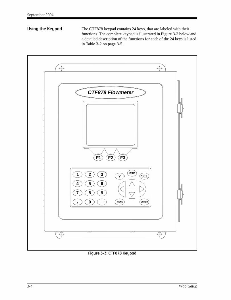
September 2004
Using the Keypad The CTF878 keypad contains 24 keys, that are labeled with their functions. The complete keypad is illustrated in Figure 3-3 below and a detailed description of the functions for each of the 24 keys is listed in Table 3-2 on page 3-5.
Figure 3-3: CTF878 Keypad
ENTERMENU
?ESC
SEL
.7
4
1
0
8
5
2
9
6
3
F1 F2 F3
CTF878 Flowmeter
3-4 Initial Setup

September 2004
Using the Keypad (cont.)Table 3-2: CTF878 Key Functions
Key FunctionSoftware Function Keys: Press to select the special functions displayed directly above them at the bottom of the screen.
12 Numeric Keys: Use to enter numeric data.
Arrow Keys: Press to scroll through function choices in measurement mode or to scroll through menu choices in programming mode. Press [<] as a backspace key in programming mode.
Help Key: Use to access on-line help. See the next section for details.
Escape Key: Press to exit menus or menu options at any time, or cancel a numeric entry.
Select Key: Use to move between data measurements on the screen.
Menu Key: Press to access the Main Menu.
Enter Key: Use to enter a particular menu or to enter selected values into CTF878 memory.
F1 F2
F3
1 2
3 4
5 6
7 8
9 0
. –
?
ESC
SEL
MENU
ENTER
Initial Setup 3-5

September 2004
Programming Site Data
Entering the Program Menu
To enter the Program Menu, press the [MENU] key at the lower right of the CTF878 keypad. The Menu Bar replaces the Status Bar at the top of the screen. Press the [ ] arrow key once to scroll from the Site Menu to the Program Menu. At the Program Menu, press [ENTER]. The screen appears similar to Figure 3-4 below. While following the programming instructions, refer to the Program Menu Map, Figure 3-21 on page 3-26.
Figure 3-4: Program Menu
To scroll to a particular option, press the [ ]or [ ] arrow keys until you reach the option. Then press [ENTER] to open the option window.
When entering parameters in an option, press:
• The [ ] key to step through the available parameters
• The [ ] key to scroll back to a previously entered parameter
• The [F2] key (Cancel) or the [ESC] key to exit an option at any time and return to Operate Mode without changing the parameters.
Site Meter Logging Service
PipeFluidPath
IO
Standard VolumeUser FunctionsCorrection Factors
0 50 100
ProgramTransducer elocity, m/s
Cross Corr
3-6 Initial Setup

September 2004
Entering the Program Menu (cont.)
Note: The Transducer, Pipe, Fluid and Path parameters are categorized under the same Transducer/Pipe menu, as shown in Figure 3-5 below. You can be more time-efficient by programming the parameters in all four entries under Transducer/Pipe before exiting the menu.
When you are highlighting a parameter in one of the four entries, and you wish to go to another entry:
1. Use the [ ] key to scroll up to the current tab (the entry that you are under).
2. Press the [ ] or [ ] key to select the parameter you want to access, then press [ENTER].
Entering Transducer Parameters
To enter the Transducer option, scroll to the Transducer tab on the Program Menu and press [ENTER]. The screen appears similar to Figure 3-5 below. To step through each parameter, press the [ ] key. Refer to the Program Menu Map, Figure 3-21 on page 3-26.
Note: If the CTF878 does not scroll to a particular parameter, the parameter is not necessary for that transducer type.
.
Figure 3-5: Transducer Option Window
The next prompt asks you to enter the transducer number (printed on the transducer itself), or to specify that you are using a special application transducer.
1. From the Type prompt, press the [ ] key to reach the Transducer prompt, and press [ENTER].
Transducer
Transducer/Pipe
Pipe Fluid Path
#304 (Shear)
0.500 0.471
Transducer
Frq Up/Dn MHz
OKCancel
°35Wedge Ang
Wedge Tmp 45 °C
Wedge SS 2480 m/s
Transducer/Pipe
Transducer
Initial Setup 3-7

September 2004
Entering Transducer Parameters (cont.)
2. A drop-down list of transducer numbers opens (see Figure 3-6 below). Press the [ ] or [ ] keys to scroll to the appropriate number, or scroll to “Special” for a special application transducer.
3. Press [ENTER] to confirm your selection..
Figure 3-6: Transducer Type Options
Upon your selection, a warning screen appears similar to Figure 3-7 below. In three out of four warnings, the Receiver Board option number appears as part of the text.
IMPORTANT: If SPECIAL is selected as the transducer type, a number does not appear, however, the warning still states that the transducer selection must match the Receiver Board.
Figure 3-7: Transducer Selection Warning Screen
Transducer
Transducer/PipeTransducer/Pipe
TransducerTransducer Pipe Fluid Path
SPECIALTransducer
Frq Up/Dn Hz
OKCancel
#304 (Shear)
#305 (Shear)
#306 (Shear)Wedge
Wedge
Wedge SS
C
m/s2484.2
Transducer/Pipe
#305 (Shear)
Transducer/Pipe
T
z
OK
This transducer selection requires a matching Option 3 (1000/888 kHz) Receiver Board. See manual for details.
Transducer/Pipe* * * WARNING * * *
3-8 Initial Setup
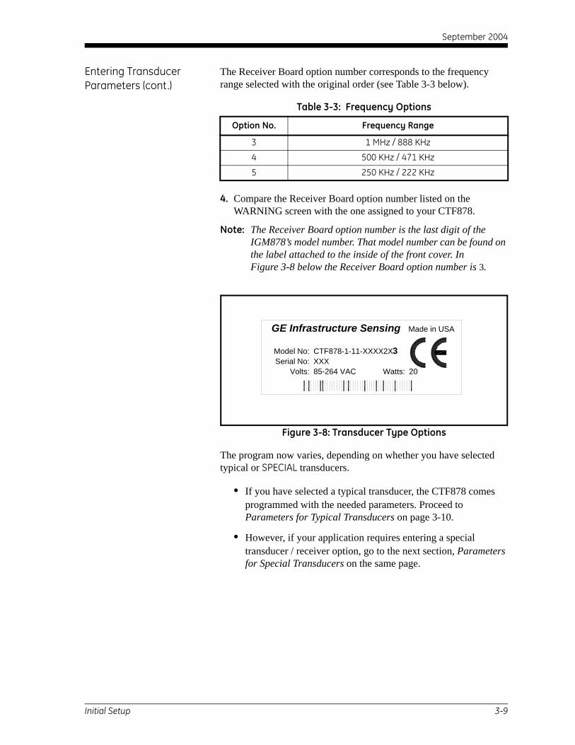
September 2004
Entering Transducer Parameters (cont.)
The Receiver Board option number corresponds to the frequency range selected with the original order (see Table 3-3 below).
4. Compare the Receiver Board option number listed on the WARNING screen with the one assigned to your CTF878.
Note: The Receiver Board option number is the last digit of the IGM878’s model number. That model number can be found on the label attached to the inside of the front cover. In Figure 3-8 below the Receiver Board option number is 3.
Figure 3-8: Transducer Type Options
The program now varies, depending on whether you have selected typical or SPECIAL transducers.
• If you have selected a typical transducer, the CTF878 comes programmed with the needed parameters. Proceed to Parameters for Typical Transducers on page 3-10.
• However, if your application requires entering a special transducer / receiver option, go to the next section, Parameters for Special Transducers on the same page.
Table 3-3: Frequency Options
Option No. Frequency Range
3 1 MHz / 888 KHz
4 500 KHz / 471 KHz
5 250 KHz / 222 KHz
Transducer/Pipe
GE Infrastructure Sensing
Model No:Serial No:
Volts:
CTF878-1-11-XXXX2XXXX85-264 VAC
Made in USA
20Watts:
3
Initial Setup 3-9

September 2004
Parameters for Typical Transducers
If a typical transducer has been selected, the user must:
1. Enter the transducer wedge temperature (Wedge Temp) text box and press [ENTER].
2. Type in the value (provided by the factory) and press [ENTER].
3. Proceed to Entry Confirmation on page 3-11.
Parameters for Special Transducers
Note: GE Infrastructure Sensing will supply the information required below with a special transducer / receiver option.
The user must enter the appropriate transducer / receiver operating frequency range.
IMPORTANT: The CTF878 flowmeter and the transducers MUST have the same fixed frequency band of operation defined by the customer's application. The up and down frequencies selected in the Programming Menu MUST correspond to those of the installed Frequency Board. The frequency printed on the transducers represents a frequency band of operation and does not always match the up or down frequencies.
1. From the Transducer prompt, press the [ ] key to reach the Frequency Up (Frq Up) prompt, and press [ENTER].
2. A drop-down list of thirty-six frequencies opens, ranging from 0.222 to 8.00 MHz. Scroll to the correct frequency, and press [ENTER].
3. Repeat the same selection process for the Frequency Down (Frq Dn) prompt.
Next, you must enter the transducer wedge angle (Wedge Ang) and wedge soundspeed (Wedge SS).
4. Scroll to the appropriate text box and press [ENTER].
5. Type in the value (provided by the factory).
Note: If you enter an incorrect numeric value, press the [ ] key to erase the last digit entered.
6. Once the value has been entered, press [ENTER] and proceed to Entry Confirmation on page 3-11.
3-10 Initial Setup
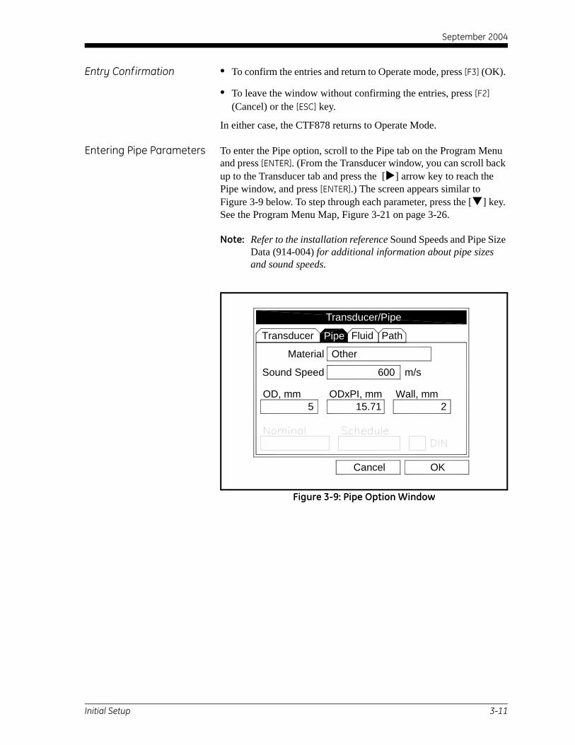
September 2004
Entry Conf irmation • To confirm the entries and return to Operate mode, press [F3] (OK).
• To leave the window without confirming the entries, press [F2] (Cancel) or the [ESC] key.
In either case, the CTF878 returns to Operate Mode.
Entering Pipe Parameters To enter the Pipe option, scroll to the Pipe tab on the Program Menu and press [ENTER]. (From the Transducer window, you can scroll back up to the Transducer tab and press the [ ] arrow key to reach the Pipe window, and press [ENTER].) The screen appears similar to Figure 3-9 below. To step through each parameter, press the [ ] key. See the Program Menu Map, Figure 3-21 on page 3-26.
Note: Refer to the installation reference Sound Speeds and Pipe Size Data (914-004) for additional information about pipe sizes and sound speeds.
Figure 3-9: Pipe Option Window
PipeTransducer Fluid Path
Other
5
Material
OKCancel
OD, mm15.71
ODxPI, mm Wall, mm2
Sound Speed 600 m/s
Transducer/Pipe
Pipe
Initial Setup 3-11

September 2004
Entering Pipe Parameters (cont.)
1. The first prompt asks you to select the pipe material.
a. Press [ENTER] to enter the material prompt.
b. A drop-down list of materials opens as shown in Figure 3-10 below. Press the [ ] or [ ] keys to scroll to the appropriate material, or scroll to “Other” for a material not on the list. Press the [ ] key to scroll down by a page, or the [ ] key to scroll up by a page.
c. Press [ENTER] to confirm the choice.
Figure 3-10: Pipe Material Options
Transduc
Mate
OD, mm
Nominal
Steel (1% Carbon)Steel (1% Carbon, hardened)Steel (Carbon)Steel (Mild)Steel (Stainless 302)Steel (Stainless 303)Steel (Stainless 304)
Transduc
Mate
OD, mm
Nominal
Copper
Aluminum (rolled)Brass
Copper (annealed)Copper (rolled)Copper / Nickel (10%)Copper / Nickel (30%)Glass (Pyrex)
Transduc
Mate
OD, mm
Nominal
Gold (hard-drawn)InconelIron (Armco)Iron (Cast)Iron (Ductile)Iron (electrolytic)MonelNickelPlastic (Acrylic)Steel (Stainless 347)
Steel (Stainless 316)Steel (Stainless 304L)
Glass (Flint)
Plastic (Polyethylene)
Titanium
Plastic (CPVC)OD, mm
Tungsten, annealedTungsten, carbide
Tin, rolled
Tungsten, drawn
Nominal
Plastic (Polypropylene)Plastic (PVC)
Transduc
Mate
Zinc, rolled
Transducer/PipeOther
Transducer/Pipe
Glass (Crown)
Transducer/Pipe
Plastic (Nylon)
Transducer/Pipe
Aluminum
3-12 Initial Setup

September 2004
Entering Pipe Parameters (cont.)
Figure 3-11: Pipe Option Window
2. For pipe diameter, two alternatives are available. The meter asks for the pipe outside diameter (OD) and wall thickness (Wall). But if you have selected certain pipe materials (carbon or stainless steel, cast iron, PVC and CPVC), you have the option of entering the pipe dimensions by a standardized schedule. Once you enter the nominal pipe size (Nominal) and identification (Schedule), the CTF878 determines the OD and wall thickness from an internal table.
If you want to use the diameter alternative (available for all materials):
a. You must select from two choices, outside diameter or circumference.
• The prompt moves to the outside diameter (OD) text box. Type the OD (in mm or in., whichever is displayed) into the box, and press [ENTER] to confirm your choice,
or• Move the prompt to the circumference (ODxPI) text box. Type
the circumference (in mm or in., whichever is displayed) into the text box, and press [ENTER] to confirm the choice.
b. In either case, the next prompt asks for the wall thickness. Type the value (in mm or in., whichever is displayed) into the box, and press [ENTER] to confirm your choice.
Note: The measurement units shown depend on the choices made in the English/Metric window or the Meter Settings menu. You can, however, change the measurement units in any text box by moving to that box and pressing the F1 key.
PipeTransducer/Pipe
PipeTransducer Fluid Path
OtherMaterial
OKCancel
OD, mm15.71
ODxPI, mm Wall, mm2
Pipe
English
Sound Speed 600 m/s
Transducer/Pipe
600
5
Initial Setup 3-13

September 2004
Entering Pipe Parameters (cont.)
If you select a material that has the Schedule option, and you wish to use that alternative:
a. The prompt asks if you wish to apply ANSI (the ANSI schedule). Press [ENTER] to select (or deselect) the ANSI box.
Note: Selecting the ANSI box enables you to use the Schedule alternative
b. Press the [ ] key twice to move the prompt to the Nominal pipe size drop-down menu. Press [ENTER] to open the menu. Scroll to the desired pipe size, and press [ENTER] to confirm your choice.
c. Press the [ ] key to move the prompt to the Schedule drop-down menu. Press [ENTER] to open the menu. Scroll to the desired schedule, and press [ENTER] to confirm the choice.
• To confirm the entries and return to Operate Mode, press [F3] (OK).
• To leave the window without confirming the entries, press [F2] (Cancel) or the [ESC] key.
In either case, the CTF878 returns to Operate Mode.
3-14 Initial Setup

September 2004
Entering Fluid Types and Speeds
To access the Fluid option, scroll to the Fluid tab on the Program Menu and press [ENTER]. (If you are already in the Transducer/Pipe form, press the [ ] arrow key to reach the Fluid window, and press [ENTER].) The screen appears similar to Figure 3-12 below. To step through each parameter, press the [ ] key. Refer to the Program Menu Map, Figure 3-21 on page 3-26.
Figure 3-12: Fluid Type Options
To select the fluid:
1. Press [ENTER] to open the drop-down menu.
2. Use the [ ] key to scroll through the options.
3. Press [ENTER] to confirm your selection.
Note: If you select Air or Natural Gas, the meter sets the soundspeed and suggests a value for K/V x 10-6. If you wish, you can change the value of K/V x 10-6.
If you select Other, you must enter values for Sound Speedand for K/V x 10-6 (see Installation Reference #914-004, Sound Speeds and Pipe Size Data).
Transducer Pipe Path
OtherFluid
K/V x 10 m /s
OKCancel
14.607
Transducer Pipe Fluid Path
Fluid
OKCancel
Air
Other
Natural Gas
-6 2
Sound Speed 600 m/s
Sound Speed
K/V x 10-6
Transducer/Pipe
FluidTransducer/Pipe
Other
Initial Setup 3-15

September 2004
Entering Fluid Types and Speeds (cont.)
• To confirm the entries and return to Operate Mode, press [F3] (OK). The CTF878 returns to Operate Mode.
• To leave the window without confirming the entries, press [F2] (Cancel) or the [ESC] key. The CTF878 returns to Operate Mode.
Entering Path Parameters To enter the Path option, scroll to the Path entry on the Program Menu and press [ENTER]. (From the Fluid window, you can scroll back up to the Fluid tab and and press [ENTER].) The screen appears similar to Figure 3-13 below. To step through each parameter, press the [ ] key. Refer to Program Menu Map, Figure 3-21 on page 3-26.
Figure 3-13: Path Window
Transducer Pipe Fluid
Tag Path
OKCancel
152.4 mm
Txdr Spacing 69.85 mm
Transducer/Pipe
Path
3-16 Initial Setup

September 2004
Path Parameters for Clamp-On Transducers
The CTF878 path menu includes two parameters:
• TAG Path
• Transducer Spacing
The TAG Path is calculated from the data entered in the Pipe parameters under Program. It can be overwritten if the user wants to use a value other than the one calculated by the flowmeter. However, it must always match the TAG Path set on the clamping fixture for reliable operation. If the path is changed on the instrument and on the clamping fixture, it must be within ±10% of the original TAG Path calculated by the flowmeter.
The Transducer Spacing is calculated from the data entered in the Transducer/Pipe/Fluid parameters. The value of Transducer Spacing is NOT used in the flowmeter’s data processing, unlike the Tag Path. It is pointless to change the Transducer Spacing in the instrument. It is only an output intended to tell the user the distance to be set between a Transmitter and a Receiver for optimal signal transmission.
Initial Setup 3-17

September 2004
Entering Analog Outputs The Analog Output option enables you to enter information to set up output parameters. To enter the option, scroll to the Main Board entry on the Program Menu and press [ENTER] (see Figure 3-14 below). Then select from the AnalogOut options and press [ENTER].
Note: Input/Output Menu options may appear in a different order, depending on where each option card is installed. Cards are numbered from right to left.
Figure 3-14: Selecting Analog Output
The screen appears similar to Figure 3-15 below. To step through each parameter, press the [ ] key. See the Program Menu Map, Figure 3-22 on page 3-27.
Figure 3-15: Analog Output Window
TransducerSite Program Meter Logging Service
PipeFluidPath
Standard VoluUser FunctionsCorrection Factors
AnalogIns (2)
0 50 100 AnalogOut(0:B)
Transducer Diagnostics Save Now
Programelocity, m/s
IOMain Board (0)
AnalogOut(0:A)
Span
Data Source
Zero
OKCancel
Analog Out
Hold Last
NO UNIT
On Error
0
100
4-20 Out SetupOff
3-18 Initial Setup

September 2004
Entering Analog Outputs (cont.)
1. The first prompt enables you to select a range to send a current signal to a recording device (see Figure 3-16 below).
a. Press [ENTER] to open the drop-down menu.
b. Scroll to the desired output from three choices: Off, 0-20 mA, and 4-20 mA.
c. Press [ENTER] to confirm your selection.
Note: If you select “Off,” you will not be able to access any other parameters in this option.
Figure 3-16: Analog Out Selection Window
2. The next prompt asks you to select the analog output type from a list of choices, as shown in Figure 3-17 below.
Figure 3-17: Data Source Selection Window
Span
Data Source
Zero
OKCancel
Analog Out
Hold LastOn Error
100
Off
0ma-20ma4ma-20ma
4-20 Out Setup
Off
OKCancelNo Unit
UserFunctionAuxInPressure
VolumeFwd TotalizerRev Totalizer
Temperature
m/sDIAG
Select Measurement
Velocity
Initial Setup 3-19

September 2004
Entering Analog Outputs (cont.)
a. Press [ENTER] to open the window.
b. Scroll to the desired output type.
c. Press [SEL] to confirm your selection.
d. The prompt then moves to a list of unit types. (The available units depend on the selection made at the Data Source prompt.) Scroll to the desired output unit.
e. Press [F3] (OK) to confirm your selection.
3. The next prompt requests the zero (base) value for the analog output. This value represents the 0/4 mA output (in flow units).
a. Press [ENTER] to open the text box.
b. Use the numeric keys to enter the desired value.
c. Press [ENTER] to confirm your selection.
4. The next prompt requests the span (full scale) value for the analog output. This value represents the 20 mA output (in flow units).
a. Press [ENTER] to open the text box.
b. Use the numeric keys to enter the desired value.
c. Press [ENTER] to confirm your selection.
5. The last prompt, On Error, asks you to select how the CTF878 will handle the analog outputs in the event of a fault condition. The meter offers three alternatives:
• Hold Last Value (hold the last good reading)
• Force Low (force the reading to 0 or 4 mA)
• Force High (force the reading to 20 mA).
a. Press [ENTER] to open the drop-down menu.
b. Scroll to the desired selection.
c. Press [ENTER] to confirm your selection.
You have completed entering data in the Analog Output option.
• To confirm the entries and return to Operate mode, press [F3] (OK). The CTF878 returns to Operate Mode.
• To leave the window without confirming the entries, press [F2] (Cancel) or the [ESC] key. The CTF878 returns to Operate Mode.
3-20 Initial Setup

September 2004
Entering Digital Outputs While resembling the Analog Output option, the Digital Output option enables you to set up parameters necessary for a digital output. To enter the option, scroll to the Digital Output entry on the Program / IO / Freq/Tot Menu and press [ENTER].
Note: Input/Output Menu options may appear in a different order, depending on where each option card is installed. Cards are numbered from right to left.
The screen appears similar to Figure 3-18 below. To step through each parameter, press the [ ] key. Refer to the Program Menu Map, Figure 3-23 on page 3-28.
Figure 3-18: Digital Output Window
1. The first prompt enables you to select the output function from three choices: Off, Pulse Totalizer, Frequency
a. Press [ENTER] to open the drop-down menu.
b. Scroll to the desired function.
c. Press [ENTER] to confirm your selection.
Note: If you select Off, you will not be able to access any other parameters in this option.
µs
Data Source
m
OKCancel
Function
1
Fwd TotalizerFwd m
Units/Pulse
Pulse Width 10
3
3
Digital OutputPulse Totalizer
Initial Setup 3-21

September 2004
Entering Digital Outputs (cont.)
2. The next prompt asks you to select the data source for the digital output. The choices vary with the function. For Pulse Totalizer (see Figure 3-18 on page 3-21), the available choices include:
• Forward Totalizer
• Reverse Totalizer
• Standard Forward Totalizer
• Standard Reverse Totalizer
a. Press [ENTER] to open the data source selection window.
b. Scroll to the desired source.
c. Press [SEL] to confirm your selection.
d. The prompt then moves to a list of unit types. (The available units depend on the selection made at the Data Source prompt.) Scroll to the desired output unit.
e. Press [F3] (OK) to confirm your selection.
3. The last set of parameters that appears depends on the selection you made at the Function prompt.
If you selected Pulse Totalizer:
The prompt asks for the units/pulse and the pulse width (in microseconds). (Figure 3-18 on page 3-21 illustrates a Digital Output window configured for the Pulse Totalizer function.) For the Units/Pulse and Pulse Width parameters:
a. Press [ENTER] to open the text box.
b. Use the numeric keys to enter the desired value.
c. Press [ENTER] to confirm your selection.
If you selected Frequency:
The prompt asks for the minimum and maximum value for the category and units selected and the minimum and maximum frequency. For each parameter:
a. Press [ENTER] to open the text box.
b. Use the numeric keys to enter the desired value.
c. Press [ENTER] to confirm your selection.
3-22 Initial Setup

September 2004
Entering a Calibration Factor
The final option in the Program Menu, Correction Factors, allows you to enter and modify the Calibration Factor. To enter the Correction Factor option, scroll to the Correction Factors selection on the Program Menu and press [ENTER]. The screen appears similar to Figure 3-19 below. To access the Calibration Factor, press the [ ] key. Refer to the Program Menu Map, Figure 3-21 on page 3-26.
Figure 3-19: Calibration Factor Window
1. To enable or disable the Calibration Factor, scroll down to the next line and select On or Off.
a. Use the [ ] and [ ] keys to scroll to the appropriate option.
b. Press [ENTER] to confirm your selection.
2. If On is selected for the Calibration Factor, scroll down to choose a Single K-Factor or a Table of K-Factors.
a. Use the [ ] and [ ] keys to scroll to the appropriate radio button.
b. Press [ENTER] to confirm your selection.
Inputs
1
Data Source
Meter K-Factor
OKCancel
OnSingle
OffTable
Calibration FactorK Factor
NO UNIT
Edit Table
Correction FactorsCalibration Factor
Initial Setup 3-23

September 2004
Entering a Calibration Factor (cont.)
If you selected Single:
1. Scroll down to the Meter K-Factor box. This feature enables a single multiplier to be applied to the flow rate reported by the CTF878.
Note: The default Meter K-Factor value is 1.
2. Press [ENTER] to open the text box.
3. Use the numeric keys to enter the desired value. The typical factor is between 0.5 and 2.00.
4. Press [ENTER] to confirm your selection.
You have completed entering data for a single Calibration Factor.
• To confirm the entries and return to Operate mode, press [F3] (OK). The CTF878 returns to Operate Mode.
• To leave the window without confirming the entries, press [F2] (Cancel) or the [ESC] key. The CTF878 returns to Operate Mode.
If you selected Table:
The menu asks, first for the data source, and then for the entry of values into the Correction Factor table. This feature allows the user to “curve fit” velocity calibration multiple data points (from several different data sources or flow variables) to the flow rate reported by the CTF878.
Note: You must select the desired measurement and unit before you can enter the data table in Edit Table.
1. Scroll down to the Data Source box.
2. Press [ENTER] to open the Data Source window. The Select Measurement window (Figure 3-17 on page 3-19) appears.
3. Enter the desired measurement and units as described on page 3-19.
4. Press [F3] (OK) to confirm your selection.
5. Scroll down to Edit Table.
3-24 Initial Setup

September 2004
Entering a Calibration Factor (cont.)
6. Press [ENTER] to open the table, which appears similar to Figure 3-20 below.
Figure 3-20: KFactor Table
7. Use the four arrow keys to move to the desired entry in the table.
8. Use the numeric keys to enter the desired value for the data source, and press [ENTER] to confirm the entry.
9. Press the [ ] key to move to the KFactor column. Use the numeric keys to enter the desired value, and press [ENTER] to confirm the entry.
10.Repeat steps 7, 8 and 9 for the remainder of the table.
11.When you have completed entering values, press [F3] (OK) to confirm the table and return to the Correction Factors window.
You have completed entering data for correction factors.
• To confirm the entries and return to Operate mode, press [F3] (OK). The CTF878 returns to Operate Mode.
• To leave the window without confirming the entries, press [F2] (Cancel) or the [ESC] key. The CTF878 returns to Operate Mode.
To aid in following the programming instructions, a complete menu map of the User Program is included in Figure 3-21 on page 3-26, Figure 3-22 on page 3-27 and Figure 3-23 on page 3-28.
OKCancel
Data Source KFactor
5
4
3
2
1
0
Edit KFactor Table
Initial Setup 3-25

September 2004
3-25
Figu
re 3
-21:
Pro
gram
Men
u M
ap -
Initi
al S
etup
Logging Service
IOVolume Functions Factors
Standard User Correction following figures
FactorCalibration
On Off
TableSingleData Source
Meter K-Factor
Initial Setup
Menu
Site Meter
Transducer Pipe Path
Special
Frequency Up
Frequency Dn
OD or ODxPI
Wall Thickness
Other
Material
Steel
Copper Glass
InconelGold
Iron
Tungsten
TitaniumTin
PlasticNickel
Monel
Zinc
Cast Iron
PVC
CPVC
Wall ThicknessOD or ODxPI
Air
Natural Gas
Other
Fluid
Fluid
Tag PathTxdr Spacing
BrassAluminumDIN
Wall ThicknessOD or ODxPI
F2 (not accept)
F3 (accept) or
See
Wall ThicknessOD or ODxPI
Sound Speed
Wedge Ang
Wedge Tmp
Wedge SS
Sound Speed
-6K/V x 10
Program

September 2004
3-26
Figu
re 3
-22:
Inp
ut/O
utpu
t Men
u M
ap -
Initi
al S
etup
for A
nalo
g O
utpu
ts
Logging Service
Volume Functions FactorsStandard User Correction
Hectare-cm
Fwd liters
Fwd m
(+)Elapsed
Hectare-m
(-)Elapsed
Hectare-m
Hectare-cm
Rev liters
Rev m
(+)Elapsed
Hectare-m
Hectare-cm
Fwd m
Fwd liters
(-)Elapsed
Hectare-m
Rev liters
Rev m
Hectare-cm
Hold Last
Force High
Force Low
Random
Ramp Up
Sin Wave
Test
Saw Wave
3
On ErrorSpanZero
Initial Setup
Menu
Site Meter
Transducer Pipe Path IOFluid
Off
0ma - 20ma
4ma - 20ma
DIAG
VolumeAuxIn
TAU
I A Up
Q A Up
I A Dn
Q A Dn
Corr SNR
Carr A Up
Carr A Dn
Cross Corr
Carr G Up
Carr G Dn
Mod G Up
Mod G Dn
meters /sec
MLiters/day
Liters/hr
Liters/min
Liters/sec
3
3
3
meters /min3
3
meters /hr3
3
3
Velocity
m/s
UserF8
UserF7
UserF6
UserF5
UserF4
UserF3
UserF2
UserF1
MMHG
KPA
Pressure
Bars
Temp K
Temp C
F2 (not accept)
F3 (accept) orProgram
C (5:B)
C (4:B)
C (5:A)
C (4:A)
mA (2:A)
mA (2:B)
Data SourceAnalog Out
IO

September 2004
3-27
Figu
re 3
-23:
Inp
ut/O
utpu
t Men
u M
ap -
Initi
al S
etup
for
Dig
ital O
utpu
ts
Volume
meters /sec
MLiters/day
Liters/hr
Liters/min
Liters/sec
3
3
3
meters /min3
3
meters /hr3
3
3
Velocity
m/s
UserF8
UserF7
UserF6
UserF5
UserF4
UserF3
UserF2
UserF1
MMHG
KPA
Pressure
Bars
Temp K
Temp C
FrequencyFunction
Data Source
Logging Service
Std. Volume User Func. Cor. Factors
Initial Setup
IO
DIAG
TAU
I A Up
Q A Up
I A Dn
Q A Dn
Corr SNR
Carr A Up
Carr A Dn
Cross Corr
Carr G Up
Carr G Dn
Mod G Up
Mod G Dn
Fwd liters
Fwd m
(+)Elapsed (-)Elapsed
Rev liters
Rev m
(+)Elapsed
Fwd m
Fwd liters
(-)Elapsed
Rev liters
Rev m
Function
Off
3
Function
Data Source
Menu
Site Meter
Transducer Pipe Path IOFluid
F2 (not accept)
F3 (accept) orProgram
IO

Chapter 4

Operation
Introduction. . . . . . . . . . . . . . . . . . . . . . . . . . . . . . . . . . . . . . . . . . . . . . . . . . . . 4-1
Displaying and Configuring Data. . . . . . . . . . . . . . . . . . . . . . . . . . . . . . . . . 4-1

September 2004
Introduction See Chapter 2, Installation, and Chapter 3, Initial Setup, to prepare the system for operation. When the meter is ready to take measurements, proceed with Displaying and Configuring Data, below.
Note: To store site data in files for current and future access, refer to Creating and Managing Sites, Chapter 2 in the CTF878 Programming Manual.
Displaying and Configuring Data
The CTF878 enables the viewing of from one to four different measurement parameters simultaneously. The screen can show these parameters not only in numeric format, but as line or bar graphs as well.
You can configure any given measurement for your particular requirements. To configure an individual measurement, press [SEL] from the Operate Mode window. A cursor appears next to the parameter closest to the upper left corner. Continuing to press [SEL] enables the cursor to scroll through the other displayed measurements. Once you have reached a particular window, pressing the [ENTER] button opens the menu for that window, as shown in Figure 4-1 below. To learn how to use the display window menu, go to Format Option on page 4-2, View Option on page 4-3, and/or Limits Option on page 4-3.
]
Figure 4-1: Display Screen After Pressing [SEL]
0 50 100
site02 2003/07/17 03:35 PM
Format View Measurement
Save Now
Volume, m/s Velocity, m/s
Corr SNR Cross Corr
Format
Operation 4-1

September 2004
Format Option Format, the first option on the menu, allows you to specify the type of notation and the number of decimal places for the measurement in that window. Press [ENTER] and the submenu shows two options: Format and Decimal Places. Press the [ ] or [ ] arrow keys to select either entry, and press [ENTER]. The screen appears similar to Figure 4-2 below. To scroll to a particular parameter or menu entry, press the [ ] or [ ] key.
Note: If the window displays a line or bar graph, the Measurement option appears instead of Format in the menu.
Figure 4-2: Number Format Window
1. The first entry, Format, asks you to select the numeric format from three choices: default, fixed decimal and scientific. Default provides the default resolution, while Fixed Decimal allows users to override the standard resolution. Scientific format displays the value in mantissa and exponent format.
a. Press [ENTER] to open the drop-down list of format choices.
b. Scroll to the appropriate selection.
c. Press [ENTER] to confirm your choice.
2. The second step asks you to choose the number of decimal places to be displayed. Available choices range from 0 to 4 places.
a. Press [ENTER] to open the drop-down list.
b. Scroll to the appropriate number.
c. Press [ENTER] to confirm your choice.
3. To confirm the entries and return to Operate mode, press [F3] (OK). To leave the window without confirming the entries, press [F2] (Cancel) or the [ESC] key.
ProgrammingFormat
OKCancel
Decimal Places
Default
Fixed DecimalScientific
Number Format
Default
4-2 Operation

September 2004
View Option The second option, View, allows you to select the presentation of a parameter in one of three formats: numeric, bar graph or line graph.
1. From the Display Menu, press the [ ] key once to reach the View option, and then press [ENTER].
2. A drop-down menu shows the three formats. Scroll to the appropriate selection.
3. Press [ENTER] to confirm your selection.
The screen immediately displays any changes. For example, if you have changed the first parameter to a line graph, the screen appears similar to Figure 4-3 below.
Figure 4-3: Screen After Format Change
Limits Option Once you have configured a parameter as a line or bar graph, you might need to change its presentation or values. The Limits option (replacing the Format option for line and bar graphs) enables you to program the minimum or maximum values displayed, the time interval and the display of the average value.
To enter the Limits option:
1. Press [SEL] from the Operate Mode window until you have reached the desired measurement.
2. Press [ENTER] to open the Display Menu.
3. Be sure the Limits option is highlighted, and press [ENTER].
4. A drop-down menu entry, Change, appears. Press [ENTER] again.
-
0 50 100
-1000010 Minutes
10000
site02 2003/07/17 03:35 PM
0
Save Now
Volume, m/s Velocity, m/s
Corr SNR Cross Corr
Operation 4-3

September 2004
Limits Option (cont.) The screen appears similar to Figure 4-4 below.
Figure 4-4: Line (or Bar) Graph Parameters Window
5. The first prompt asks for the minimum value shown in the graph.
a. Press [ENTER] to open the text box.
b. Use the numeric keys to enter the desired value.
c. Press [ENTER] to confirm the value.
6. Repeat the procedure in step 5 to enter the maximum value.
A line graph involves two more prompts.
7. The next prompt asks for the display interval.
a. Press [ENTER] to open the text box. Use the numeric keys to enter the desired number. Press [ENTER] to confirm the value.
b. The second box asks for the interval in terms of seconds, minutes, hours, or days. Press [ENTER] to open the drop-down menu, and then press the [ ] or [ ] keys to move to the desired parameter. Press [ENTER] to confirm the entry.
8. The final three prompts ask for details of the graph configuration: if you want to use lines, plot the average value, or show the minimum and maximum values. Press the [ ] key to step through each value, and press [ENTER] to add a given detail as part of the graph.
9. When you have configured the graph, press [F3] (OK) to confirm the graph settings, or press [F2] (Cancel) to cancel the changes.
The screen returns to Operate Mode, and displays any changes.
OKCancel
Use Lines
Plot Average Value
Show Minimum and Maximum
Minimum
Maximum 10000
10 Minutes
TauSet Line Graph Parameters
-10000
4-4 Operation

September 2004
Measurement Option On occasion, you might need to change the actual parameter measured in a given window.The Measurement option enables you to reconfigure the window with one of several categories of data and appropriate English or metric measurement units.
To enter the Measurement option:
1. Press [SEL] from the Operate Mode window until you have reached the measurement you want to replace.
2. Press [ENTER] to open the Display Menu.3. Be sure the Measurement option is highlighted, and press [ENTER]. The screen appears similar to Figure 4-5 below. The left column displays categories of data, while the right column displays English and metric measurement units (or, with the Diagnostics source shown, a list of diagnostics parameters).
4. Use the [ ] and [ ] arrow keys to reach the desired category of data, and press [SEL].
5. Then use the [ ] or [ ] arrow keys to select the desired measurement unit (or diagnostic parameter). Press [F3] (OK) to confirm the entry, or [F2] (Cancel) to cancel the changes.
6. The screen returns to Operate Mode, and displays any changes.
Figure 4-5: Measurement Menu Window
Delta-T
OKCancelNo Unit
Rev Totalizer
VelocityUserFunctionAuxInPressureTemperatureVolumeFwd Totalizer
Corr SNRCarr A UpCarr A Dn
I A UpQ A UpI A DnQ A Dn
Carr G Up
TAU
Select Measurement
DIAG
Operation 4-5

September 2004
Customizing the Display Screen
You might wish to display one or two parameters, or customize the soft keys to quickly access particular menus. The Site Menu enables you to make more comprehensive changes in your display screen.
To enter the Site Menu, press the [MENU] key at the lower right of the CTF878 keypad. The Menu Bar replaces the Status Bar at the top of the screen. Scroll to Site using the [ ] and [ ] keys. Press [ENTER] or the [ ] arrow key. The screen now appears similar to Figure 4-6 below. While following the programming instructions, refer to Figure 4-12 on page 4-12.
Figure 4-6: Site Menu
• To specify the number of parameters displayed, go to page 4-7.
• To customize or clear softkeys (FKeys), go to page 4-8.
Program Meter Logging Service
Save Now1 View2 View3 View4 ViewFKeysAbout
100
Transducer Diagnostics Save Now
SiteSite Manager Velocity, m/s
Cross Corr
4-6 Operation

September 2004
Specifying the Number of Displayed Parameters
As mentioned earlier, the CTF878 can display one to four different measurement parameters simultaneously. However, sometimes you might wish to display only one or two parameters. To change the number of open display windows from within the Site Menu (see Figure 4-6 on page 4-6), use the [ ]or [ ] arrow keys to move to the desired number of views (1 View, 2 Views, etc.) Press [ENTER].
The screen displays the designated number of windows. Forexample, Figure 4-7 below shows the screen displayed in Figure 4-3 on page 4-3, reconfigured for a single view.
Figure 4-7: Display Screen Configured for Single View
Note: The CTF878 opens display windows from left to right and from top to bottom, starting from the upper left; that is, if you press “1 View,” the parameter displayed in the upper left window appears. If you press “2 Views,” the parameters shown in the two top windows appear. The view for “3 Views” adds the window in the lower left, and that for “4 Views” adds the window in the lower right.
-1000010 Minutes
10000 0
-5000
-2000
2000
5000
Save Now
Program Meter Logging Service
Volume, m/sSite
Operation 4-7

September 2004
Customizing Softkeys When the screen is in Operate Mode, you might wish to access a particular submenu frequently without the trouble of scrolling through menus. Customizing the softkeys ([F1], [F2] and [F3]) allows you to access up to three submenus by pressing the associated softkey. You can customize a softkey from the Site Menu or from within a particular menu.
• To customize a softkey from within the Site Menu:
1. From the Site Menu (shown in Figure 4-6 on page 4-6), use the [ ] or [ ] arrow keys to move to the FKeys entry on the menu. Press [ENTER]. The screen now appears similar to Figure 4-8 below.
Figure 4-8: FKeys Menu
2. Use the [ ] or [ ] arrow keys to move to the desired FKey (1, 2 or 3) entry on the menu. Press [ENTER]. The Configure FKey window opens, as shown in Figure 4-9 on page 4-9.
Program Meter Logging Service
Save Now1 View2 View3 View4 View
Site Manager
About F2F3Clear F1Clear F2Clear F3 Save NowDTransducer
SiteVelocity, m/s
Cross Corr
FKeys F1
4-8 Operation
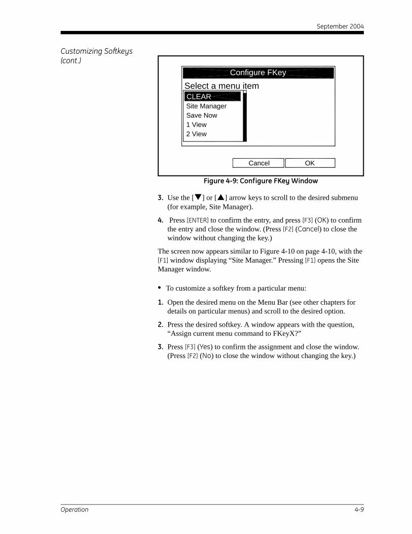
September 2004
Customizing Softkeys (cont.)
Figure 4-9: Configure FKey Window
3. Use the [ ] or [ ] arrow keys to scroll to the desired submenu (for example, Site Manager).
4. Press [ENTER] to confirm the entry, and press [F3] (OK) to confirm the entry and close the window. (Press [F2] (Cancel) to close the window without changing the key.)
The screen now appears similar to Figure 4-10 on page 4-10, with the [F1] window displaying “Site Manager.” Pressing [F1] opens the Site Manager window.
• To customize a softkey from a particular menu:
1. Open the desired menu on the Menu Bar (see other chapters for details on particular menus) and scroll to the desired option.
2. Press the desired softkey. A window appears with the question, “Assign current menu command to FKeyX?”
3. Press [F3] (Yes) to confirm the assignment and close the window. (Press [F2] (No) to close the window without changing the key.)
OKCancel
Select a menu item
Site ManagerSave Now1 View2 View
Configure FKey
CLEAR
Operation 4-9

September 2004
Customizing Softkeys (cont.)
Figure 4-10: Display Screen with Modified Softkey
• To clear a softkey:
1. From the Site Menu (shown in Figure 4-6 on page 4-6), use the [ ] or [ ] arrow keys to move to the FKeys entry on the menu. Press [ENTER]. The screen now appears similar to Figure 4-8 on page 4-8.
2. Use the [ ] or [ ] arrow keys to move to the desired Clear FKey (1, 2 or 3) entry on the menu. Press [ENTER].
The softkey window clears. You can also clear the softkey through the Configure FKey window, by selecting (Clear) as an entry, pressing [ENTER] and then [F3] (OK).
Note: Since the customized softkeys are saved globally, they will remain, even if you change site files.
-1000010 Minutes
10000 0
-5000
-2000
2000
5000
Save Now
Program Meter Logging Service
Site Manager
SiteVolume, m/s
4-10 Operation
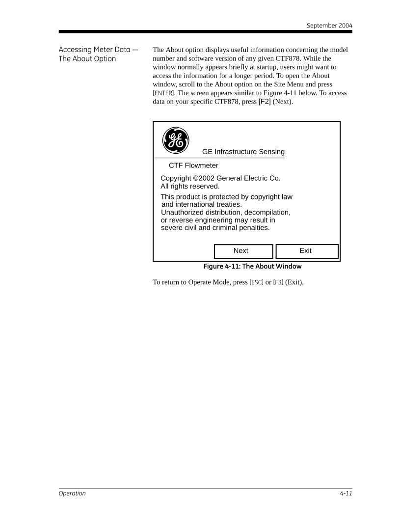
September 2004
Accessing Meter Data —The About Option
The About option displays useful information concerning the model number and software version of any given CTF878. While the window normally appears briefly at startup, users might want to access the information for a longer period. To open the About window, scroll to the About option on the Site Menu and press [ENTER]. The screen appears similar to Figure 4-11 below. To access data on your specific CTF878, press [F2] (Next).
Figure 4-11: The About Window
To return to Operate Mode, press [ESC] or [F3] (Exit).
GE Infrastructure Sensing
CTF Flowmeter
Copyright ©2002 General Electric Co.All rights reserved.This product is protected by copyright lawand international treaties.Unauthorized distribution, decompilation, or reverse engineering may result insevere civil and criminal penalties.
Next Exit
g
Operation 4-11

September 2004
Figure 4-12: Site Menu Map
Men
u
P rog
ram
Met
erLo
ggin
gSe
rvic
e
Site
Save
Now
1 Vi
ew
3 Vi
ew
4 Vi
ew
FKey
sAb
out
New
Ope
n
Save
Sav e
As
2 Vi
ewFi
leSo
rt
Cle a
r F3
Clea
r F2
C lea
r F1
F3F2F1
Ma n
ager
Ref r
esh
Rena
me
Mes
sage
Del
ete
Nam
e
File
Nam
e
Nam
e
F ile
Mes
.
By N
ame
B y D
ate
Men
u Ite
m
Men
u Ite
m
Men
u Ite
m
Not
e: P
ress
[F2]
(Can
cel)
to c
ance
l th e
ent
ries
and
retu
rn to
Men
u.P r
ess
[F3]
(OK)
to c
o nfir
m th
e en
trie
s a n
d re
tur n
to M
enu .
Site
4-12 Operation

Chapter 5

Specifications
Features . . . . . . . . . . . . . . . . . . . . . . . . . . . . . . . . . . . . . . . . . . . . . . . . . . . . . . . 5-1
General System Specifications . . . . . . . . . . . . . . . . . . . . . . . . . . . . . . . . . . . 5-2
System Electronics Specifications . . . . . . . . . . . . . . . . . . . . . . . . . . . . . . . . 5-3
Transducer, Preamplifier and Fixture Specifications . . . . . . . . . . . . . . . . 5-5
Pipe Specifications. . . . . . . . . . . . . . . . . . . . . . . . . . . . . . . . . . . . . . . . . . . . . . 5-6

September 2004
Features
Built-In Flow Computer • Programmable from the keypad.
• Outputs velocity and other flow parameters in real time, while simultaneously handling other activities such as programming, logging, calibration and output of data and diagnostics.
Data Logging • Memory capacity for over 6,900 data points in linear or circular format for standard and error logs.
• Keypad programmable for log units, log interval, and start and stop times.
Display Functions • Graphic display shows flow in numeric or graphic format.
• Also displays logged data and diagnostics.
PC-Interface Software • PanaView™ Instrument Interface Software option links the CTF878 to a PC computer. Package includes CD-ROM, interconnection cable (please specify type needed), and manual.
Specif ications 5-1

September 2004
General System Specifications
Hardware Configuration
Channel Options: Single channel.
Transducer / Preamplif ier Options:
3” North America gual box termination for all four transducers.3” ATEX gual box termination for all four transducers.
Package Options: Standard: Epoxy-coated aluminum (FM/CSA-approved for Div. 2, Class I, Groups A, B, C & D areas).Optional: Stainless Steel or Explosion-Proof.
Physical Characteristics Standard Size: 14.24 x 11.4 x 5.12 in. (36.2 x 29 x 13 cm)Standard Weight: 11 lb (5 kg)
Flow Range and Accuracy (% of reading)
Pipe Sizes 6” to 30” ANSI
Velocity Range for Acoustically Conductive Gases
Minimum Velocity = 3.6 ft/secMaximum Velocity = 150 ft/sec (a higher velocity may be possible)
Note: The CTF878 requires flow to modulate the ultrasonic signal. The meter will go into error at velocities below approximately 3.6 ft/sec, but will resume function if negative flow is established with velocities greater than 3.6 ft/sec in the reverse direction.
Velocity Accuracy 2% of reading
Repeatability 0.6%
Rangeability 43:1
Update Rate 2 Seconds
Response Time (to within 2% of f inal value)
25-45 Seconds
5-2 Specif ications

September 2004
System Electronics Specifications
User Interface
Keypad 24-key, rubberized, tactile-membrane keypad
Display 240 x 200 pixel LCD graphical display w/ backlight
User I/O
Digital Input/Outputs: Standard: RS232Optional: RS485
Analog Inputs Select up to three boards of the following two types (see note below):Analog Input Board with two isolated 4-20mA inputs and 24V loop powerRTD Input Board with two isolated 3-wire RTD inputs; Span –148° to 600°F (–100° to 333°C)
Analog Outputs Standard: Two isolated 0/4-20mA current outputs, 550Ω max. loadOptional: Select up to three additional output boards, each with four isolated 0/4-20mA outputs, 1kΩ maximum load (see note below).
Totalizer/Frequency Outputs
Select up to three Totalizer/Frequency Output Boards, each with four outputs per board, 10kHz maximum (see note below). All boards allow software selectable functioning in two modes:Totalizer Mode: Pulse per defined unit of parameter (e.g., 1 pulse/ft3).Frequency Mode: Pulse frequency proportional to magnitude of parameter (e.g., 10 Hz = 1 ft3/min).
Alarm Relays Select up to two boards of the following types (see note below):General Purpose Relay Board with three Form-C relays; 120VAC, 28VDC max., 5A max.; DC 30W max., AC 60VAHermetically Sealed Relay Board with three hermetically sealed Form-C relays; 120VAC, 28VDC max., 2A max.; DC 56W max., AC 60VA.
Note: There can be a maximum of six input/output option boards at one time.
Cable Type and Length Standard: Set of four coaxial cables, type RG62a/u, 10ft (3m) long.Optional: Lengths to 500 ft (153 m).
Specif ications 5-3

September 2004
Power Input
AC Line Options Input Voltage: 85-264 VAC, 47-63 HzInput Power: 15-35 watts (option dependent)Power Factor: 0.5Peak Inrush Current: < 1.4 A after 10 ms, 120V 60 Hz < 2.5 A after 10 ms, 240V 50 HzLine Dropout Holdup Time: 10 ms minimum per EN61000-4-11
Protection Built-in mains power surge/lightning protection.
Environmental Requirements
Operating Temperature: 14° to 130°F (–10° to 55°C)
Storage Temperature –40° to 158°F (–40° to 70°C)
Operational and Storage Humidity
0% to 90% RH (Non-Condensing)
Vibration (Unit) 10 Hz to 75 Hz Sinewave, 0.020” Peak-to-Peak Displacement
Vibration (Unit w/ Packaging)
10 Hz to 75 Hz Sinewave, 0.020” Peak-to-Peak Displacement
Regulatory, Safety, Certifications
• LVD 950, LVD 1010
• CE Radiated/Conducted, Emissions/Immunity, Burst, Surge, ESD
• NEMA 4X
5-4 Specif ications

September 2004
Transducer, Preamplifier and Fixture Specifications
Ultrasonic Flow Transducers
Temperature Range C-RL Transducers’ Family: –40° to +266°F (–40° to +130°C)
Materials Stainless Steel and Plastic
Housing Options: Explosion-Proof (suitable for Class 1, Div. 1, Groups C & D) Certification pendingFlameproof (ATEX CE Ex II G T6, IP68) Certification pending.Weatherproof (NEMA 4X, IP65)
Receive Transducer Preamplifier
Temperature Range Ambient Storage & Operating Temperature: –40° to 167°F (–40° to 75°C)Process Temperature: (Rated the same as the transducer)
Housing Options External Preamplifier mounted inside a 3” North America gual boxExternal Preamplifier mounted inside a 3” ATEX gual box
Clamping Fixtures 6 to 8 in. (152 to 203 mm) pipe: CFT–V88 to 12 in. (203 to 305 mm) pipe: CFT–V1212 to 30 in. (305 to 762 mm) pipe: CFT–PI
Transducer Fixtures Fixture Materials: Anodized aluminum blocks with stainless steel rod, chain or strap.Mounting Couplant: CPL-16Damping Material: DMP-CTF-pipe size
Specif ications 5-5

September 2004
Pipe Specifications
Materials All metal and plastics. No lined pipes.
Sizes 6 to 30 in. NB ANSI (152 to 762 mm NB) and larger.
Wall Thickness Up to SCH 80. Thicker walled pipes may be possible; consult the factory.
Pressure Requirements Pmin = 0 psig
5-6 Specif ications

Appendix A
CE Mark Compliance
Introduction. . . . . . . . . . . . . . . . . . . . . . . . . . . . . . . . . . . . . . . . . . . . . . . . . . . . A-1
Wiring . . . . . . . . . . . . . . . . . . . . . . . . . . . . . . . . . . . . . . . . . . . . . . . . . . . . . . . . . A-1

September 2004
Introduction For CE Mark compliance, the CTF878 flowmeter must be wired in accordance with the instructions in this appendix.
IMPORTANT: CE Mark compliance is required for all units intended for use in EEC countries.
Wiring The CTF878 must be wired with the recommended cable, and all connections must be properly shielded and grounded. Refer to Table A-1 below for the specific requirements.
External Grounding For CE Mark compliance, the electronics enclosure and the transducer fixture must each have an external ground wire attached.
Note: If the CTF878 is wired as described in this appendix, the unit will comply with the EMC Directive 89/336/EEC.
Table A-1: Wiring Modifications
Connection Cable TypeTermination Modification
TransducerArmored RG62 a/u or conduit
None - grounded using a cable gland.
Input/Output
22 AWG shielded(e.g. Baystate #78-1197)
Terminate using a cable gland.
Armored conduit None - grounded using a cable gland.
Power
14 AWG, 3 conductor, shielded(e.g. Belden #19364)
Terminate using a cable gland.
Armored Conduit None - grounded using a cable gland.
Shielding
For CE compliance, power and I/O cables must be shielded. Cables are to be terminated within a cable gland at the CTF878. Shielded cable is not required when installations include metal conduit.
CE Mark Compliance A-1

Appendix B

Data Records
Option Cards Installed . . . . . . . . . . . . . . . . . . . . . . . . . . . . . . . . . . . . . . . . . . B-1
Initial Setup Data . . . . . . . . . . . . . . . . . . . . . . . . . . . . . . . . . . . . . . . . . . . . . . . B-2

September 2004
Option Cards Installed Whenever an option card is installed in one of the CTF878’s expansion slots, record the type of card and any additional setup information in the appropriate row of Table B-2 below.
Table B-2: Option Cards InstalledSlot # Type of Option Card Additional Setup Information
0 Analog Outputs (A, B)
1
2
3
4
5
6
Data Records B-1

September 2004
Initial Setup Data After the CTF878 flowmeter has been installed, some initial setup data must be entered via the User Program, prior to operation. Record that information in Table B-3 below.
Table B-3: Initial Setup DataGeneral Information
Model # ReferenceSoftware Vers. Date
Serial #Signal Processing Parameters
Velocity AveragingC Corr AvgTransducer Parameters Pipe Parameters
Std. Trans. # Pipe MaterialSpec. Trans. # Pipe O.D.Frequency Up Pipe WallFrequency Dn Fluid Type Air / Natural Gas / Other
TAG path Cal. FactorTransdcr Spacing
K-factor TableK Factor # Data Source K-Factor K Factor # Data Source K-Factor
1 132 143 154 165 176 187 198 209 21
10 2211 2312 24
B-2 Data Records

September 2004
Index
AAbout Option . . . . . . . . . . . . . . . . . . . . . . . . 4-11Alarms Option Card
Connecting . . . . . . . . . . . . . . . . . . . . . . . . 2-34Fail-Safe Operation . . . . . . . . . . . . . . . . . 2-34
Analog Inputs Option CardConnecting . . . . . . . . . . . . . . . . . . . . . . . . 2-35Pin Assignments. . . . . . . . . . . . . . . . . . . . 2-35Rating . . . . . . . . . . . . . . . . . . . . . . . . . . . . 2-35
Analog OutputsConnecting . . . . . . . . . . . . . . . . . . . . . . . . 2-32Entering . . . . . . . . . . . . . . . . . . . . . . . . . . 3-18Initial Setup . . . . . . . . . . . . . . . . . . 3-26, 3-27Menu Map . . . . . . . . . . . . . . . . . . . 3-26, 3-27Span (Full Scale) Value . . . . . . . . . . . . . . 3-20Terminal Block. . . . . . . . . . . . . . . . . . . . . 2-32Zero (Base) Value. . . . . . . . . . . . . . . . . . . 3-20
Analog Outputs Option CardConnecting . . . . . . . . . . . . . . . . . . . . . . . . 2-37
BBar Graph Display . . . . . . . . . . . . . . . . . . . . . 4-3
CCable
Serial Port . . . . . . . . . . . . . . . . . . . . . . . . .2-32Transducer. . . . . . . . . . . . . . . . . . . . 2-26, 2-27
Calibration Factor . . . . . . . . . . . . . . . . . . . . .3-23CE Mark Compliance . . . . . . . . . . . . . . .2-1, A-1CFT-PI Clamping Fixture
Damping Material . . . . . . . . . . . . . . . . . . .2-17Installation. . . . . . . . . . . . . . . . . . . . . . . . .2-13Locating . . . . . . . . . . . . . . . . . . . . . . . . . .2-13Mounting. . . . . . . . . . . . . . . . . . . . . . . . . .2-15Preparation . . . . . . . . . . . . . . . . . . . . . . . .2-14Sanding the Pipe . . . . . . . . . . . . . . . . . . . .2-14Setting the TAG path. . . . . . . . . . . . . . . . .2-14Setting the Transducer Spacing. . . . . . . . .2-14
CFT-V Clamping Fixture . . . . . . . . . . . . . . . .2-8Damping Material . . . . . . . . . . . . . . . . . . . .2-9Installation. . . . . . . . . . . . . . . . . . . . . . . . . .2-7Locating . . . . . . . . . . . . . . . . . . . . . . . . . . .2-7Mounting. . . . . . . . . . . . . . . . . . . . . . . . . .2-12Preparation . . . . . . . . . . . . . . . . . . . . . . . . .2-8Sanding the Pipe . . . . . . . . . . . . . . . . . . . . .2-8TAG path. . . . . . . . . . . . . . . . . . . . . . . . . . .2-8Yokes. . . . . . . . . . . . . . . . . . . . . . . . . . . . .2-11
Clamping Fixture . . . . . . . . . . . . . . . . . . . . . .1-3CFT-PI. . . . . . . . . . . . . . . . . . . . . . . . . . . .2-13CFT-V . . . . . . . . . . . . . . . . . . . . . . . . . . . . .2-7
Clearing Softkeys . . . . . . . . . . . . . . . . . . . . .4-10Configuring the Display . . . . . . . . . . . . . . . . .4-1Connecting
See Part NameConnectors, Electrical . . . . . . . . . . . . . . . . . . .2-4
Index 1
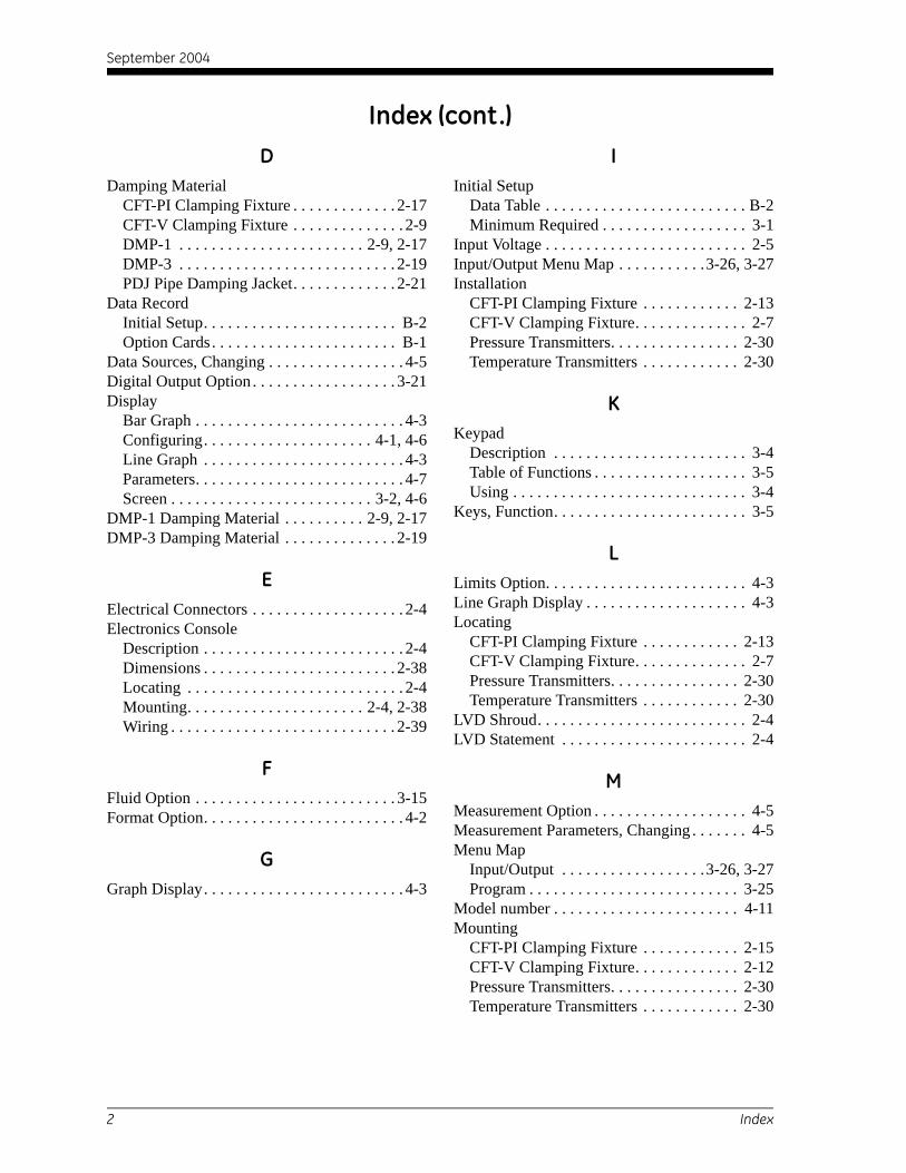
September 2004
Index (cont.)
DDamping MaterialCFT-PI Clamping Fixture . . . . . . . . . . . . . 2-17CFT-V Clamping Fixture . . . . . . . . . . . . . . 2-9DMP-1 . . . . . . . . . . . . . . . . . . . . . . . 2-9, 2-17DMP-3 . . . . . . . . . . . . . . . . . . . . . . . . . . . 2-19PDJ Pipe Damping Jacket. . . . . . . . . . . . . 2-21
Data RecordInitial Setup. . . . . . . . . . . . . . . . . . . . . . . . B-2Option Cards . . . . . . . . . . . . . . . . . . . . . . . B-1
Data Sources, Changing . . . . . . . . . . . . . . . . . 4-5Digital Output Option . . . . . . . . . . . . . . . . . . 3-21Display
Bar Graph . . . . . . . . . . . . . . . . . . . . . . . . . . 4-3Configuring. . . . . . . . . . . . . . . . . . . . . 4-1, 4-6Line Graph . . . . . . . . . . . . . . . . . . . . . . . . . 4-3Parameters. . . . . . . . . . . . . . . . . . . . . . . . . . 4-7Screen . . . . . . . . . . . . . . . . . . . . . . . . . 3-2, 4-6
DMP-1 Damping Material . . . . . . . . . . 2-9, 2-17DMP-3 Damping Material . . . . . . . . . . . . . . 2-19
EElectrical Connectors . . . . . . . . . . . . . . . . . . . 2-4Electronics Console
Description . . . . . . . . . . . . . . . . . . . . . . . . . 2-4Dimensions . . . . . . . . . . . . . . . . . . . . . . . . 2-38Locating . . . . . . . . . . . . . . . . . . . . . . . . . . . 2-4Mounting. . . . . . . . . . . . . . . . . . . . . . 2-4, 2-38Wiring . . . . . . . . . . . . . . . . . . . . . . . . . . . . 2-39
FFluid Option . . . . . . . . . . . . . . . . . . . . . . . . . 3-15Format Option. . . . . . . . . . . . . . . . . . . . . . . . . 4-2
GGraph Display. . . . . . . . . . . . . . . . . . . . . . . . . 4-3
IInitial Setup
Data Table . . . . . . . . . . . . . . . . . . . . . . . . . B-2Minimum Required . . . . . . . . . . . . . . . . . . 3-1
Input Voltage . . . . . . . . . . . . . . . . . . . . . . . . . 2-5Input/Output Menu Map . . . . . . . . . . .3-26, 3-27Installation
CFT-PI Clamping Fixture . . . . . . . . . . . . 2-13CFT-V Clamping Fixture. . . . . . . . . . . . . . 2-7Pressure Transmitters. . . . . . . . . . . . . . . . 2-30Temperature Transmitters . . . . . . . . . . . . 2-30
KKeypad
Description . . . . . . . . . . . . . . . . . . . . . . . . 3-4Table of Functions . . . . . . . . . . . . . . . . . . . 3-5Using . . . . . . . . . . . . . . . . . . . . . . . . . . . . . 3-4
Keys, Function. . . . . . . . . . . . . . . . . . . . . . . . 3-5
LLimits Option. . . . . . . . . . . . . . . . . . . . . . . . . 4-3Line Graph Display . . . . . . . . . . . . . . . . . . . . 4-3Locating
CFT-PI Clamping Fixture . . . . . . . . . . . . 2-13CFT-V Clamping Fixture. . . . . . . . . . . . . . 2-7Pressure Transmitters. . . . . . . . . . . . . . . . 2-30Temperature Transmitters . . . . . . . . . . . . 2-30
LVD Shroud. . . . . . . . . . . . . . . . . . . . . . . . . . 2-4LVD Statement . . . . . . . . . . . . . . . . . . . . . . . 2-4
MMeasurement Option . . . . . . . . . . . . . . . . . . . 4-5Measurement Parameters, Changing . . . . . . . 4-5Menu Map
Input/Output . . . . . . . . . . . . . . . . . .3-26, 3-27Program . . . . . . . . . . . . . . . . . . . . . . . . . . 3-25
Model number . . . . . . . . . . . . . . . . . . . . . . . 4-11Mounting
CFT-PI Clamping Fixture . . . . . . . . . . . . 2-15CFT-V Clamping Fixture. . . . . . . . . . . . . 2-12Pressure Transmitters. . . . . . . . . . . . . . . . 2-30Temperature Transmitters . . . . . . . . . . . . 2-30
2 Index

September 2004
Index (cont.)
OOption CardsAlarms . . . . . . . . . . . . . . . . . . . . . . . . . . . 2-34Analog Inputs . . . . . . . . . . . . . . . . . . . . . . 2-35Analog Outputs . . . . . . . . . . . . . . . . . . . . 2-37Data Record . . . . . . . . . . . . . . . . . . . . . . . .B-1RTD Inputs . . . . . . . . . . . . . . . . . . . . . . . . 2-37Setup Information Table. . . . . . . . . . . . . . .B-1Totalizer/Frequency Outputs . . . . . . . . . . 2-36
OutputAnalog, Entering . . . . . . . . . . . . . . . . . . . 3-18Digital. . . . . . . . . . . . . . . . . . . . . . . . . . . . 3-21
PParameters, Displayed . . . . . . . . . . . . . . . . . . 4-7Path
Entering . . . . . . . . . . . . . . . . . . . . . . . . . . 3-16Option. . . . . . . . . . . . . . . . . . . . . . . . . . . . 3-16Parameters, Clamp-on Transducers . . . . . 3-17
PDJ Pipe Damping Jacket . . . . . . . . . . . . . . 2-21Pipe
Diameter, Entering . . . . . . . . . . . . . . . . . . 3-13Dimensions, Schedule for . . . . . . . . . . . . 3-13Material . . . . . . . . . . . . . . . . . . . . . . . . . . 3-12
PowerConnecting . . . . . . . . . . . . . . . . . . . . . . . . . 2-5Powering On and Off . . . . . . . . . . . . . . . . . 3-1Terminal Block. . . . . . . . . . . . . . . . . . . . . . 2-5
Pressure TransmittersInstallation . . . . . . . . . . . . . . . . . . . . . . . . 2-30Locating . . . . . . . . . . . . . . . . . . . . . . . . . . 2-30Mounting . . . . . . . . . . . . . . . . . . . . . . . . . 2-30Wiring. . . . . . . . . . . . . . . . . . . . . . . . . . . . 2-30
Program Menu Map . . . . . . . . . . . . . . . . . . . 3-25
RRS232 Interface, Wiring . . . . . . . . . . . . . . . 2-32RS232 Port
See Serial PortRS485 Interface, Wiring . . . . . . . . . . . . . . . 2-33RTD
Inputs Option Card . . . . . . . . . . . . . . . . . . 2-37Temperature Transmitter . . . . . . . . . . . . . 2-30
SSanding the Pipe
CFT-PI Clamping Fixture . . . . . . . . . . . . .2-14CFT-V Clamping Fixture . . . . . . . . . . . . . .2-8
ScreenDescription . . . . . . . . . . . . . . . . . . . . . . . . .3-2Display . . . . . . . . . . . . . . . . . . . . . . . . . . . .4-6
Serial PortCable . . . . . . . . . . . . . . . . . . . . . . . . . . . . .2-32Connecting . . . . . . . . . . . . . . . . . . . . . . . .2-32Pin Assignments . . . . . . . . . . . . . . . . . . . .2-32Terminal Block . . . . . . . . . . . . . . . . . . . . .2-32
SettingTAG path. . . . . . . . . . . . . . . . . . . . . . . . . . .2-8Transducer Spacing. . . . . . . . . . . . . . . . . . .2-8
ShroudLVD. . . . . . . . . . . . . . . . . . . . . . . . . . . . . . .2-4Plastic . . . . . . . . . . . . . . . . . . . . . . . . . . . . .2-4
SoftkeysClearing. . . . . . . . . . . . . . . . . . . . . . . . . . .4-10Customizing . . . . . . . . . . . . . . . . . . . . . . . .4-8
Software Version. . . . . . . . . . . . . . . . . . . . . .4-11Span (Full Scale) Value. . . . . . . . . . . . . . . . .3-20Special Transducers
Entering Data . . . . . . . . . . . . . . . . . . . . . .3-10
Index 3

September 2004
Index (cont.)
TTAG pathCFT-PI Clamping Fixture . . . . . . . . . . . . . 2-14CFT-V Clamping Fixture . . . . . . . . . . . . . . 2-8
Temperature TransmittersInstallation . . . . . . . . . . . . . . . . . . . . . . . . 2-30Locating . . . . . . . . . . . . . . . . . . . . . . . . . . 2-30Mounting. . . . . . . . . . . . . . . . . . . . . . . . . . 2-30Wiring . . . . . . . . . . . . . . . . . . . . . . . . . . . . 2-30
Terminal BlockAnalog Outputs . . . . . . . . . . . . . . . . . . . . . 2-32Power . . . . . . . . . . . . . . . . . . . . . . . . . . . . . 2-5Serial Port - RS232 . . . . . . . . . . . . . . . . . . 2-32Transducers . . . . . . . . . . . . . . . . . . . . . . . . 2-27
Totalizer/Frequency Option CardConnecting . . . . . . . . . . . . . . . . . . . . . . . . 2-36
Transducer Option . . . . . . . . . . . . . . . . . . . . . 3-7Transducer Spacing
CFT-PI Clamping Fixture . . . . . . . . . . . . . 2-14CFT-V Clamping Fixture . . . . . . . . . . . . . . 2-8
TransducersCable Connections . . . . . . . . . . . . . . . . . . 2-26Cables . . . . . . . . . . . . . . . . . . . . . . . . . . . . 2-27Clamp-On . . . . . . . . . . . . . . . . . . . . . . . . . 3-17Description . . . . . . . . . . . . . . . . . . . . . . . . . 1-3Entering Data for . . . . . . . . . . . . . . . . . . . . 3-7Entering Number . . . . . . . . . . . . . . . . . . . . 3-7Identifying. . . . . . . . . . . . . . . . . . . . . . . . . 2-26Installation, with CFT-PI Fixture . . . . . . . 2-24Installation, with CFT-V Fixture . . 2-23, 2-24Location . . . . . . . . . . . . . . . . . . . . . . . . . . 2-23Mounting. . . . . . . . . . . . . . . . . . . . . . . . . . 2-24Special. . . . . . . . . . . . . . . . . . . . . . . . . . . . 3-10Wiring . . . . . . . . . . . . . . . . . . 2-26, 2-27, 2-29
UUnpacking. . . . . . . . . . . . . . . . . . . . . . . . . . . . 2-1
VView Option . . . . . . . . . . . . . . . . . . . . . . . . . . 4-3Voltage, Input . . . . . . . . . . . . . . . . . . . . . . . . . 2-5
WWiring
CE Mark Compliance . . . . . . . . . . . . . . . . A-1Electronics Console . . . . . . . . . . . . . . . . . 2-39Option Card . . . . . . . . . . . . . . See Card NamePressure Transmitters. . . . . . . . . . . . . . . . 2-30RS232 Interface . . . . . . . . . . . . . . . . . . . . 2-32RS485 Interface . . . . . . . . . . . . . . . . . . . . 2-33Temperature Transmitters . . . . . . . . . . . . 2-30Terminal Block . . . . . . . . . . .See Block NameTransducers . . . . . . . . . . . . . . 2-26, 2-27, 2-29
YYokes, Positioning . . . . . . . . . . . . . . . . . . . . 2-11
ZZero (Base) Valuet . . . . . . . . . . . . . . . . . . . . 3-20
4 Index

GE InfrastructureSensing
DECLARATIONOF
CONFORMITY
CERT-DOC-H0 August 2004
TÜV ESSENISO 9001
U.S.
TÜV
We, Panametrics Limited Shannon Industrial Estate
Shannon, County Clare Ireland
declare under our sole responsibility that the
CTF878 Ultrasonic Flowmeter
to which this declaration relates, are in conformity with the following standards:
• EN 61326:1998, Class A, Annex A, Continuous Unmonitored Operation
• EN 61010-1:1993 + A2:1995, Overvoltage Category II, Pollution Degree 2
following the provisions of the 89/336/EEC EMC Directive and the 73/23/EEC Low Voltage Directive.
Shannon - April 15, 2004Mr. James Gibson
GENERAL MANAGER

GE InfrastructureSensing
DECLARATIONDE
CONFORMITE
CERT-DOC-H0 August 2004
TÜV ESSENISO 9001
U.S.
TÜV
Nous, Panametrics Limited Shannon Industrial Estate
Shannon, County Clare Ireland
déclarons sous notre propre responsabilité que les
CTF878 Ultrasonic Flowmeter
rélatif á cette déclaration, sont en conformité avec les documents suivants:
• EN 61326:1998, Class A, Annex A, Continuous Unmonitored Operation
• EN 61010-1:1993 + A2:1995, Overvoltage Category II, Pollution Degree 2
suivant les régles de la Directive de Compatibilité Electromagnétique 89/336/EEC et de la Directive Basse Tension 73/23/EEC.
Shannon - April 15, 2004Mr. James Gibson
DIRECTEUR GÉNÉRAL

GE InfrastructureSensing KONFORMITÄTS-
ERKLÄRUNG
CERT-DOC-H0 August 2004
TÜV ESSENISO 9001
U.S.
TÜV
Wir, Panametrics Limited Shannon Industrial Estate
Shannon, County Clare Ireland
erklären, in alleiniger Verantwortung, daß die Produkte
CTF878 Ultrasonic Flowmeter
folgende Normen erfüllen:
• EN 61326:1998, Class A, Annex A, Continuous Unmonitored Operation
• EN 61010-1:1993 + A2:1995, Overvoltage Category II, Pollution Degree 2
gemäß den Europäischen Richtlinien, Niederspannungsrichtlinie Nr.: 73/23/EG und EMV-Richtlinie Nr.: 89/336/EG.
Shannon - April 15, 2004Mr. James Gibson
GENERALDIREKTOR

USA
1100 Technology Park DriveBillerica, MA 01821-4111Web: www.gesensing.com
Ireland
Shannon Industrial EstateShannon, County ClareIreland