
MODEL #: UVU-140-A & UVU-140-AR · Unit I GENERAL INFORMATION DESCRIPTION The UVU-140-A &...
24
MODEL #: UVU-140-A & UVU-140-AR UNITIZED ULTRAVIOLET FIRE DETECTOR REVISED: DECEMBER, 1999 REV. uvu140a-aroct99.wpd
Transcript of MODEL #: UVU-140-A & UVU-140-AR · Unit I GENERAL INFORMATION DESCRIPTION The UVU-140-A &...
MODEL #: UVU-140-A & UVU-140-AR
UNITIZED ULTRAVIOLET FIRE DETECTOR
REVISED: DECEMBER, 1999REV. uvu140a-aroct99.wpd

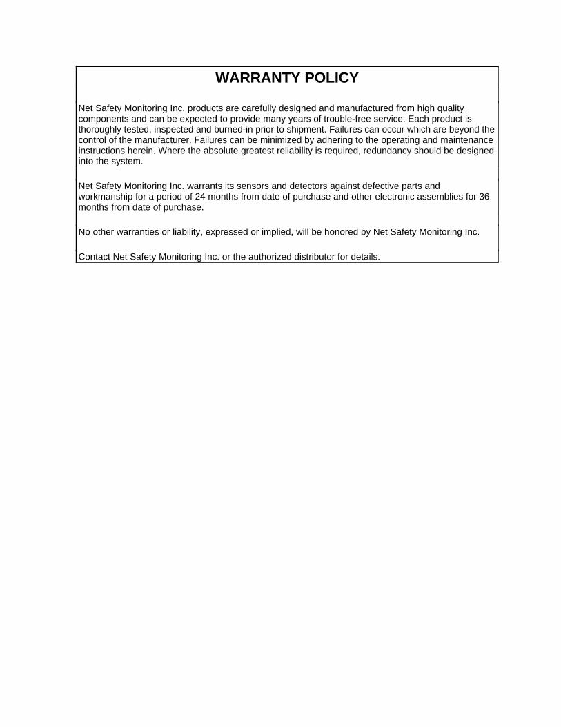
WARRANTY POLICY
Net Safety Monitoring Inc. products are carefully designed and manufactured from high qualitycomponents and can be expected to provide many years of trouble-free service. Each product isthoroughly tested, inspected and burned-in prior to shipment. Failures can occur which are beyond thecontrol of the manufacturer. Failures can be minimized by adhering to the operating and maintenanceinstructions herein. Where the absolute greatest reliability is required, redundancy should be designedinto the system.
Net Safety Monitoring Inc. warrants its sensors and detectors against defective parts andworkmanship for a period of 24 months from date of purchase and other electronic assemblies for 36months from date of purchase.
No other warranties or liability, expressed or implied, will be honored by Net Safety Monitoring Inc.
Contact Net Safety Monitoring Inc. or the authorized distributor for details.

Table of Contents
Unit I - GENERAL INFORMATIONDESCRIPTION . . . . . . . . . . . . . . . . . . . . . . . . . . . . . . . . . . . . . . . . . . . . . . . . . . . . . . . . . . . . . . . . . . . . . . . . . . 1FEATURES . . . . . . . . . . . . . . . . . . . . . . . . . . . . . . . . . . . . . . . . . . . . . . . . . . . . . . . . . . . . . . . . . . . . . . . . . . . . . 1DETECTOR SPECIFICATIONS . . . . . . . . . . . . . . . . . . . . . . . . . . . . . . . . . . . . . . . . . . . . . . . . . . . . . . . . . . . . . . 1
Figure 1 - Detector Dimensions . . . . . . . . . . . . . . . . . . . . . . . . . . . . . . . . . . . . . . . . . . . . . . . . . . . . . . . 3Figure 2 - Swivel Mount Dimensions . . . . . . . . . . . . . . . . . . . . . . . . . . . . . . . . . . . . . . . . . . . . . . . . . . . . 3Figure 3 - JB4 - UV - T Junction Box Side View . . . . . . . . . . . . . . . . . . . . . . . . . . . . . . . . . . . . . . . . . . . 3Figure 4 - JB4-UV-T Junction Box Dimensions . . . . . . . . . . . . . . . . . . . . . . . . . . . . . . . . . . . . . . . . . . . . 3
Unit II - UV FIRE DETECTIONSYSTEM APPLICATION . . . . . . . . . . . . . . . . . . . . . . . . . . . . . . . . . . . . . . . . . . . . . . . . . . . . . . . . . . . . . . . . . . . 4DETECTOR SENSITIVITY . . . . . . . . . . . . . . . . . . . . . . . . . . . . . . . . . . . . . . . . . . . . . . . . . . . . . . . . . . . . . . . . . . 4
SPECTRAL SENSITIVITY RANGE . . . . . . . . . . . . . . . . . . . . . . . . . . . . . . . . . . . . . . . . . . . . . . . . . . . . . 4Figure 5 - Various Spectral Distributions . . . . . . . . . . . . . . . . . . . . . . . . . . . . . . . . . . . . . . . . . . . . . . . . . 5CONE OF VISION . . . . . . . . . . . . . . . . . . . . . . . . . . . . . . . . . . . . . . . . . . . . . . . . . . . . . . . . . . . . . . . . . 6Figure 6 - Detector Cone of Vision . . . . . . . . . . . . . . . . . . . . . . . . . . . . . . . . . . . . . . . . . . . . . . . . . . . . . 6
SYSTEM SENSITIVITY . . . . . . . . . . . . . . . . . . . . . . . . . . . . . . . . . . . . . . . . . . . . . . . . . . . . . . . . . . . . . . . . . . . . 6Table 1 - Detector Sensitivity Settings . . . . . . . . . . . . . . . . . . . . . . . . . . . . . . . . . . . . . . . . . . . . . . . . . . . 7Table 2 - Alarm Response Delay Settings . . . . . . . . . . . . . . . . . . . . . . . . . . . . . . . . . . . . . . . . . . . . . . . . 7Figure 7 - Dip Switch Operation and Location . . . . . . . . . . . . . . . . . . . . . . . . . . . . . . . . . . . . . . . . . . . . . 7
Unit III - SYSTEM INSTALLATIONINSTALLATION . . . . . . . . . . . . . . . . . . . . . . . . . . . . . . . . . . . . . . . . . . . . . . . . . . . . . . . . . . . . . . . . . . . . . . . . . . 7
GENERAL WIRING REQUIREMENTS . . . . . . . . . . . . . . . . . . . . . . . . . . . . . . . . . . . . . . . . . . . . . . . . . . 7CONNECTION DIAGRAM FOR UVU-140-A . . . . . . . . . . . . . . . . . . . . . . . . . . . . . . . . . . . . . . . . . . . . . . 8Figure 8 - Wiring for UVU-140-A . . . . . . . . . . . . . . . . . . . . . . . . . . . . . . . . . . . . . . . . . . . . . . . . . . . . . . . 8CONNECTION DIAGRAM FOR UVU-140-AR . . . . . . . . . . . . . . . . . . . . . . . . . . . . . . . . . . . . . . . . . . . . . 9Figure 9 - Wiring for UVU-140-AR . . . . . . . . . . . . . . . . . . . . . . . . . . . . . . . . . . . . . . . . . . . . . . . . . . . . . 9Table 3 - Coil & Relay Settings Table . . . . . . . . . . . . . . . . . . . . . . . . . . . . . . . . . . . . . . . . . . . . . . . 9
POSITION AND DENSITY OF DETECTORS . . . . . . . . . . . . . . . . . . . . . . . . . . . . . . . . . . . . . . . . . . . . . . . . . . . 10MOUNTING THE DETECTOR . . . . . . . . . . . . . . . . . . . . . . . . . . . . . . . . . . . . . . . . . . . . . . . . . . . . . . . 10Figure 10 - Detector with Swivel Mount Assembly . . . . . . . . . . . . . . . . . . . . . . . . . . . . . . . . . . . . . . . . . 10
Unit IV - SYSTEM OPERATIONSTARTUP PROCEDURE . . . . . . . . . . . . . . . . . . . . . . . . . . . . . . . . . . . . . . . . . . . . . . . . . . . . . . . . . . . 11CHECKOUT PROCEDURE . . . . . . . . . . . . . . . . . . . . . . . . . . . . . . . . . . . . . . . . . . . . . . . . . . . . . . . . . 11AUTOMATIC vi TEST . . . . . . . . . . . . . . . . . . . . . . . . . . . . . . . . . . . . . . . . . . . . . . . . . . . . . . . . . . . . . 11MANUAL vi TEST PROCEDURE . . . . . . . . . . . . . . . . . . . . . . . . . . . . . . . . . . . . . . . . . . . . . . . . . . . . . 11MANUAL CHECK PROCEDURE . . . . . . . . . . . . . . . . . . . . . . . . . . . . . . . . . . . . . . . . . . . . . . . . . . . . . 12
NORMAL OPERATION . . . . . . . . . . . . . . . . . . . . . . . . . . . . . . . . . . . . . . . . . . . . . . . . . . . . . . . . . . . . . . . . . . . 12FIRE RESPONSE . . . . . . . . . . . . . . . . . . . . . . . . . . . . . . . . . . . . . . . . . . . . . . . . . . . . . . . . . . . . . . . . 12Table 4 - Current & Relay Output Conditions . . . . . . . . . . . . . . . . . . . . . . . . . . . . . . . . . . . . . . . . . . . . 13
Unit V - MAINTENANCEROUTINE MAINTENANCE . . . . . . . . . . . . . . . . . . . . . . . . . . . . . . . . . . . . . . . . . . . . . . . . . . . . . . . . . 13TROUBLESHOOTING . . . . . . . . . . . . . . . . . . . . . . . . . . . . . . . . . . . . . . . . . . . . . . . . . . . . . . . . . . . . 14
CLEANING VIEWING WINDOW AND REFLECTOR . . . . . . . . . . . . . . . . . . . . . . . . . . . . . . . . . . . . . . 14REPOSITIONING vi ADJUSTMENT ALLEN SCREW . . . . . . . . . . . . . . . . . . . . . . . . . . . . . . . . . . . . . . 14
DEVICE REPAIR AND RETURN . . . . . . . . . . . . . . . . . . . . . . . . . . . . . . . . . . . . . . . . . . . . . . . . . . . . . 14
Appendix ANet Safety Monitoring Inc. Electrostatic Sensitive Device Handling Procedure . . . . . . . . . . . . . . . . . . . . . . . . . . . . . I
Appendix BCommon Ultra-Violet Absorbing Gases . . . . . . . . . . . . . . . . . . . . . . . . . . . . . . . . . . . . . . . . . . . . . . . . . . . . . . . . . II
Appendix CWire Resistance In Ohms . . . . . . . . . . . . . . . . . . . . . . . . . . . . . . . . . . . . . . . . . . . . . . . . . . . . . . . . . . . . . . . . . . III
- 1 -
Unit IGENERAL INFORMATION
DESCRIPTION
The UVU-140-A & UVU-140-AR fire detectors provide fast, reliable flame detection in a wide variety ofapplications. The automatic visual integrity (vi) feature allows for a continuous check of optical surfaces,sensitivity and electronic circuitry of the unitized fire detector. Fire and fault identification areaccomplished by the use of specific current output levels and relay contacts (UVU-140-AR only).
The UVU-140-A & UVU-140-AR fire detectors respond to UV radiation over the range of 185 to 260nanometres. They are not sensitive to direct or reflected sunlight nor to normal artificial lighting.
The UVU-140-A & UVU-140-AR fire detectors are housed in explosion-proof enclosures that are designedto meet most national and international standards. They are available in anodized aluminum or optionalstainless steel.
The UVU-140-AR unitized fire controller connects to a JBR-T-ASSY which consists of a junction box, tworelays and a terminal connector board. The JBR-T-ASSY has large, easy access, spring tension terminalsand a user selectable dip switch which allows the operator to select relay and coil status conditions (seeTable 3).
The UVU-140-A & UVU-140-AR fire detectors are typically mounted with a swivel mounting assembly(see Figure 9).
FEATURES
< Instantaneous response to ultraviolet radiation< Automatic and manual visual integrity (vi) testing< Adjustable sensitivity and time delay< All automatic test functions are performed with the system on-line< Alarm and automatic fault identification indicated by a 4 to 20mA output< Relay outputs for fire and fault identification (UVU-140-AR only)< The fault relay is normally energized and non-latching (UVU-140-AR only)
DETECTOR SPECIFICATIONS
< Operating Voltage Range:24Vdc nominal: 10.5 to 32Vdc
<< Power Consumption (UVU-140-A):1.92 Watts nominal 2.4 Watts maximum @ 24Vdc80mA nominal 100mA maximum @ 24Vdc
< Power Consumption (UVU-140-AR):2.4 Watts nominal (fault relay energized) @ 24Vdc
2.9 Watts maximum (fire & fault relays energized) @ 24Vdc100mA nominal @ 24Vdc 120mA maximum @ 24Vdc
<< Temperature Range:Operating: -40ºC to +85ºC (-40°F to +185°F)Storage: -55ºC to +125ºC (-65°F to +257°F)
- 2 -
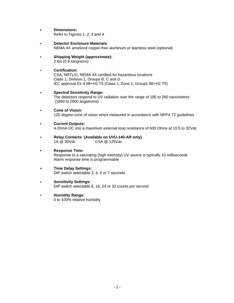
<< Dimensions:Refer to Figures 1, 2, 3 and 4
< Detector Enclosure Materials:NEMA 4X anodized copper-free aluminum or stainless steel (optional)
< Shipping Weight (approximate):2 lbs (0.9 kilograms)
< Certification:CSA, NRTL/C, NEMA 4X certified for hazardous locationsClass 1, Division 1, Groups B, C and DIEC approval Ex d IIB+H2 T5 (Class 1, Zone 1, Groups IIB+H2 T5)
< Spectral Sensitivity Range:The detectors respond to UV radiation over the range of 185 to 260 nanometres (1850 to 2600 angstroms)
< Cone of Vision:120 degree cone of vision when measured in accordance with NFPA 72 guidelines
< Current Outputs:4-20mA DC into a maximum external loop resistance of 600 Ohms at 10.5 to 32Vdc
< Relay Contacts: (Available on UVU-140-AR only)1A @ 30Vdc 0.5A @ 125Vac
<< Response Time:Response to a saturating (high intensity) UV source is typically 10 milliseconds Alarm response time is programmable
<< Time Delay Settings:DIP switch selectable 3, 4, 5 or 7 seconds
< Sensitivity Settings:DIP switch selectable 8, 16, 24 or 32 counts per second
< Humidity Range:0 to 100% relative humidity
- 3 -
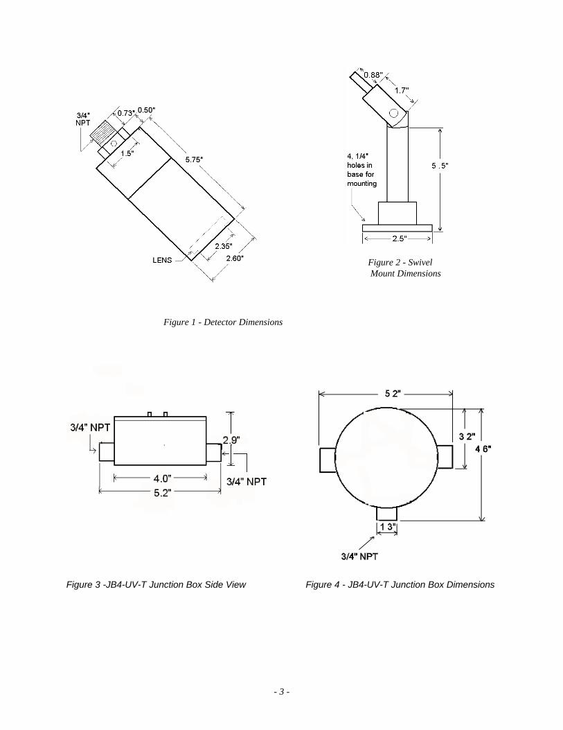
Figure 1 - Detector Dimensions
Figure 2 - Swivel Mount Dimensions
Figure 3 -JB4-UV-T Junction Box Side View Figure 4 - JB4-UV-T Junction Box Dimensions
- 4 -
Unit IIUV FIRE DETECTION
SYSTEM APPLICATION
The UVU-140-A & UVU-140-AR fire detectors respond instantly to ultraviolet radiation emitted by aflame. These devices are designed for use in hazardous locations and are suitable for use in outdoorapplications.
Typical applications for UV detection systems< around highly combustible materials< when instantaneous response to flame is needed or where automated fire protection is
required< protection of large capital investments
Petroleum Products Handling< petroleum loading terminals< offshore platforms< pipeline stations< tank farms< refineries< engine rooms
Gaseous Fuel Handling< butane and propane loading and storage< pipeline compressor stations< gas gathering facilities< LNG loading, transfer and storage < hydrogen < gas turbines
Other Processes< paint spray booths< chemical and petrochemical production< powder coating booths
Automated fire protection systems also have applications in any manufacturing or research facility wherethe potential of fire may be low to moderate, but the losses due to a fire would be high.
DETECTOR SENSITIVITY
SPECTRAL SENSITIVITY RANGE
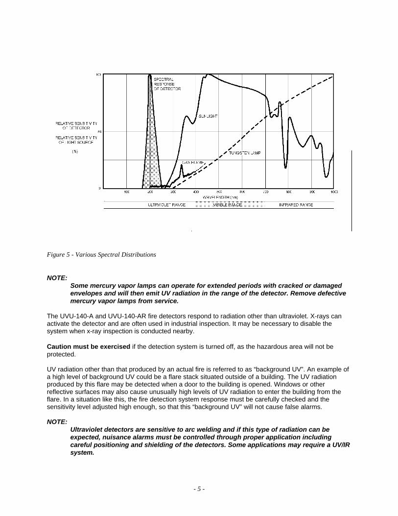
The UVU-140-A & UVU-140-AR fire detectors respond to radiation wavelengths of 185 to 260nanometres (1850 to 2600 angstroms). Figure 5 illustrates the range of sensitivity and compares thisrange to other forms of radiation. Note that UV radiation reaching the earth from the sun does not extendinto the sensitivity range of the detector. Nor does radiation from normal artificial lighting, such asfluorescent, mercury vapor and incandescent lamps.
- 5 -
Figure 5 - Various Spectral Distributions
NOTE:Some mercury vapor lamps can operate for extended periods with cracked or damaged
envelopes and will then emit UV radiation in the range of the detector. Remove defectivemercury vapor lamps from service.
The UVU-140-A and UVU-140-AR fire detectors respond to radiation other than ultraviolet. X-rays canactivate the detector and are often used in industrial inspection. It may be necessary to disable thesystem when x-ray inspection is conducted nearby.
Caution must be exercised if the detection system is turned off, as the hazardous area will not beprotected.
UV radiation other than that produced by an actual fire is referred to as “background UV”. An example ofa high level of background UV could be a flare stack situated outside of a building. The UV radiationproduced by this flare may be detected when a door to the building is opened. Windows or otherreflective surfaces may also cause unusually high levels of UV radiation to enter the building from theflare. In a situation like this, the fire detection system response must be carefully checked and thesensitivity level adjusted high enough, so that this “background UV” will not cause false alarms.
NOTE:Ultraviolet detectors are sensitive to arc welding and if this type of radiation can beexpected, nuisance alarms must be controlled through proper application includingcareful positioning and shielding of the detectors. Some applications may require a UV/IRsystem.

- 6 -
CONE OF VISION
The UVU-140-A & UVU-140-AR fire detectors have a nominal 120 degree cone of vision when measuredin accordance to NFPA 72 guidelines. Figure 6 shows the cone of vision and detector response to a UVsource at various distances. The practical application distance is up to about 80 feet (25 metres). Thedistance is directly related to the intensity of the ultraviolet radiation source. Programming the UVU-140-A & UVU-140-AR fire detectors to require a high count rate results in low system sensitivity. For a list ofsome common UV absorbing chemical vapors see Appendix B.
Figure 6 - Detector Cone of Vision
SYSTEM SENSITIVITY
The UV tube count rate generated by different fires at the same distance is unpredictable. Generally if afire doubles in size, the tube response is increased by about 60 percent. The UVU-140-A & UVU-140-ARdetectors have selectable sensitivity settings which allow for various applications regardless of theseverity of the hazard and the action required if a fire occurs. The system can be adjusted to varioussensitivity levels by setting the detectors to respond at a pre-determined detector count rate. The countrate is dependent upon the intensity of the ultraviolet radiation reaching the detector, which in turndepends on the type of fuel, temperature, flame size, distance from the detector and concentration of UVabsorbing vapors present.
Setting the UVU-140-A & UVU-140-AR detectors to respond to a low count rate results in high systemsensitivity.
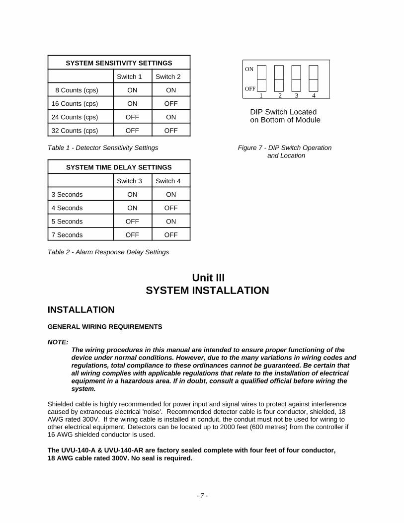
Adjustments are made by setting the DIP switch on the bottom of the internal module. The factorysettings are 5 second time delay at 24 counts per second (cps), the fire relay is de-energized andlatching.
- 7 -
DIP Switch Locatedon Bottom of Module
ON
OFF1 2 3 4
SYSTEM SENSITIVITY SETTINGS
Switch 1 Switch 2
8 Counts (cps) ON ON
16 Counts (cps) ON OFF
24 Counts (cps) OFF ON
32 Counts (cps) OFF OFF
Table 1 - Detector Sensitivity Settings Figure 7 - DIP Switch Operation and Location
SYSTEM TIME DELAY SETTINGS
Switch 3 Switch 4
3 Seconds ON ON
4 Seconds ON OFF
5 Seconds OFF ON
7 Seconds OFF OFF
Table 2 - Alarm Response Delay Settings
Unit III SYSTEM INSTALLATION
INSTALLATION
GENERAL WIRING REQUIREMENTS
NOTE:The wiring procedures in this manual are intended to ensure proper functioning of thedevice under normal conditions. However, due to the many variations in wiring codes andregulations, total compliance to these ordinances cannot be guaranteed. Be certain thatall wiring complies with applicable regulations that relate to the installation of electricalequipment in a hazardous area. If in doubt, consult a qualified official before wiring thesystem.
Shielded cable is highly recommended for power input and signal wires to protect against interferencecaused by extraneous electrical 'noise'. Recommended detector cable is four conductor, shielded, 18AWG rated 300V. If the wiring cable is installed in conduit, the conduit must not be used for wiring toother electrical equipment. Detectors can be located up to 2000 feet (600 metres) from the controller if16 AWG shielded conductor is used.
The UVU-140-A & UVU-140-AR are factory sealed complete with four feet of four conductor, 18 AWG cable rated 300V. No seal is required.
- 8 -
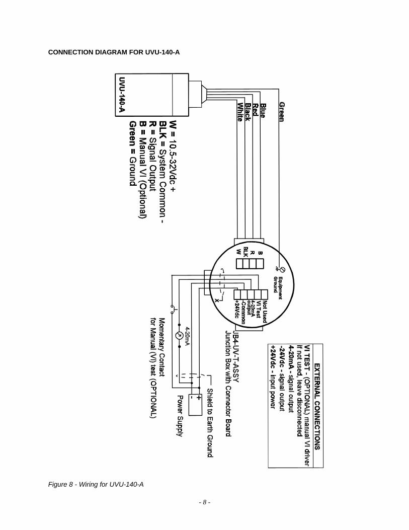
CONNECTION DIAGRAM FOR UVU-140-A
Figure 8 - Wiring for UVU-140-A

- 9 -
CONNECTION DIAGRAM FOR UVU-140-AR
Figure 9 - Wiring for UVU-140-AR
- 10 -
POSITION AND DENSITY OF DETECTORS
The UVU-140-A & UVU-140-AR fire detectors have a nominal 120 degree cone of vision when measuredin accordance to NFPA 72 guidelines. In an application such as a loading dock with a ceiling height of 25feet (7.5 metres) where it is desired to have complete detector coverage at floor level and a detector ismounted 2 feet (0.6 metres) from the ceiling and pointed straight down, the distance from the detector tothe designated level would be 23 feet (7 metres). The detector has a 120 degree cone of vision andwould cover a circular area 80 feet (24 metres) in diameter at floor level. A sketch of the area to becovered will indicate the number of detectors required to monitor the area. Detectors should be placed asclose as practical to the expected fire hazard.
NOTE:Do not mount UV detectors close to the ceiling of enclosed buildings if smoke mightaccumulate before the break-out of flame. It is preferable to mount the detectors on wallsa few feet (about 1 metre) below the ceiling where they may respond before beingobscured by smoke. Consider shortening time delay settings when smoke is expected toaccumulate during a fire. If dense smoke is likely to accumulate prior to flame (as in anelectrical fire), supplement UV detectors with other protection.
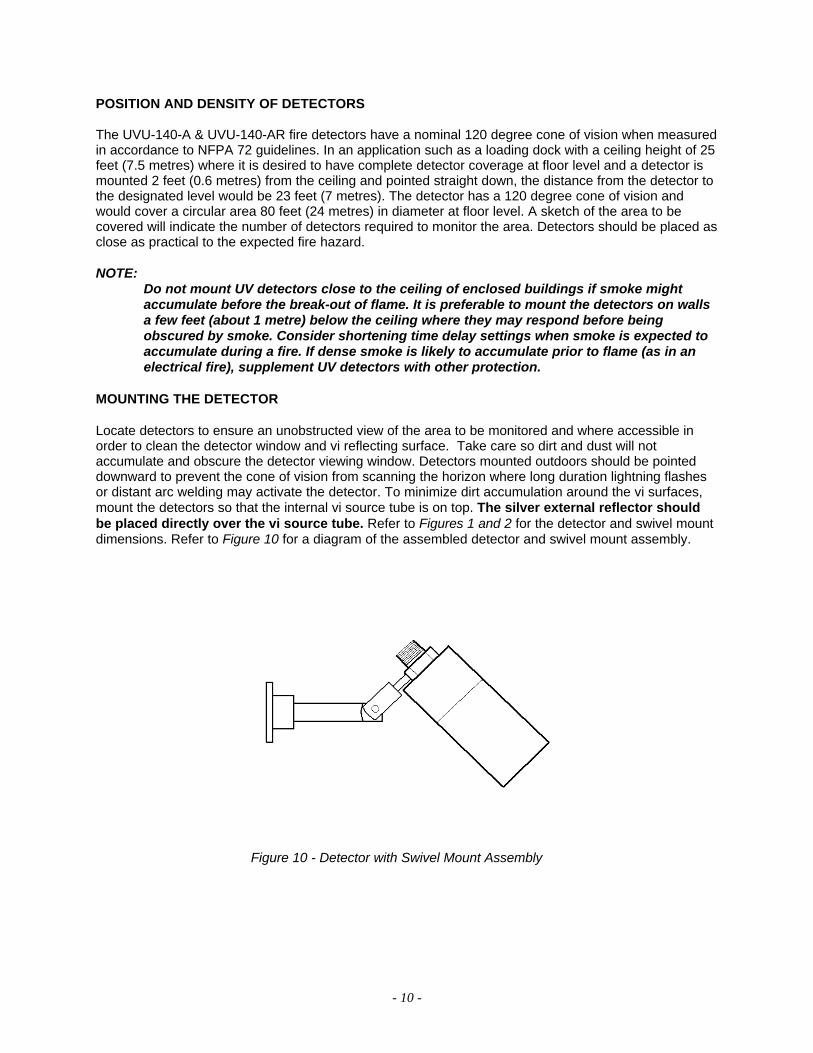
MOUNTING THE DETECTOR
Locate detectors to ensure an unobstructed view of the area to be monitored and where accessible inorder to clean the detector window and vi reflecting surface. Take care so dirt and dust will notaccumulate and obscure the detector viewing window. Detectors mounted outdoors should be pointeddownward to prevent the cone of vision from scanning the horizon where long duration lightning flashesor distant arc welding may activate the detector. To minimize dirt accumulation around the vi surfaces,mount the detectors so that the internal vi source tube is on top. The silver external reflector shouldbe placed directly over the vi source tube. Refer to Figures 1 and 2 for the detector and swivel mountdimensions. Refer to Figure 10 for a diagram of the assembled detector and swivel mount assembly.
Figure 10 - Detector with Swivel Mount Assembly
- 11 -
Unit IVSYSTEM OPERATION
STARTUP PROCEDURE
NOTE:Be sure that the detector is correctly aimed at the potential hazard and that noobstructions interfere with its line of vision. UV absorbing gases should not exist betweenthe detector and the potential hazard.
CHECKOUT PROCEDURE
CAUTION:When testing the system, be sure to secure all output devices to prevent unwantedactivation of equipment and remember to place the same devices back into service whenthe check-out is complete.
AUTOMATIC vi TEST
NOTE:The automatic vi system continuously monitors the operation of the detector. However, itis important that the system be manually checked using the MANUAL check procedure(described on page 12) on a regular basis. The whole system (including externalequipment) should be checked periodically using a UV test lamp to simulate a fire.
The detector performs an automatic vi test every 30 seconds. If the automatic vi test fails, the UVU-140-A or UVU-140-AR current output will decrease to 2mA indicating a dirty window or otherobstruction in front of the detector tube. The UVU-140-A or UVU-140-AR current output will remain at2mA until the problem is corrected. If the obstruction was only temporary, the detector will return tonormal operation with a current output of 4mA the next time the automatic vi test is successful.
MANUAL vi TEST PROCEDURE
The detector has a manual vi input. The manual vi test is performed by connecting this input to thesystem power for the duration of the test. This can be done by connecting a momentary contactpushbutton between system power and the manual vi input, and then holding the pushbutton to performthe test.
NOTE:The manual vi feature is optional on the UVU-140-A (If not used, leave unconnected ortied to system common).
CAUTION:The detector will stay in the manual vi test mode as long as the manual vi input is held atthe system power voltage. During the manual vi test all other detector functions aredisabled. It is therefore imperative that, after this test is performed, the manual vi testinput be released.
- 12 -
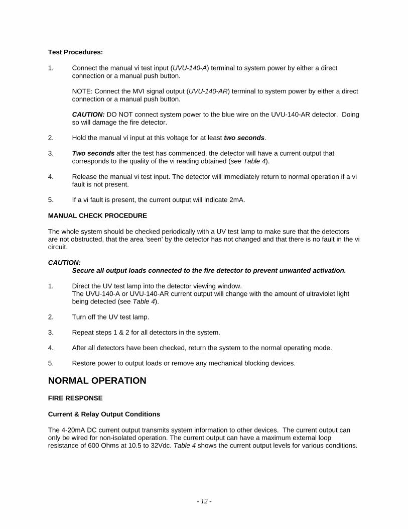
Test Procedures:
1. Connect the manual vi test input (UVU-140-A) terminal to system power by either a directconnection or a manual push button.
NOTE: Connect the MVI signal output (UVU-140-AR) terminal to system power by either a directconnection or a manual push button.
CAUTION: DO NOT connect system power to the blue wire on the UVU-140-AR detector. Doingso will damage the fire detector.
2. Hold the manual vi input at this voltage for at least two seconds.
3. Two seconds after the test has commenced, the detector will have a current output thatcorresponds to the quality of the vi reading obtained (see Table 4).
4. Release the manual vi test input. The detector will immediately return to normal operation if a vifault is not present.
5. If a vi fault is present, the current output will indicate 2mA.
MANUAL CHECK PROCEDURE
The whole system should be checked periodically with a UV test lamp to make sure that the detectorsare not obstructed, that the area ‘seen’ by the detector has not changed and that there is no fault in the vicircuit.
CAUTION:Secure all output loads connected to the fire detector to prevent unwanted activation.
1. Direct the UV test lamp into the detector viewing window. The UVU-140-A or UVU-140-AR current output will change with the amount of ultraviolet lightbeing detected (see Table 4).
2. Turn off the UV test lamp.
3. Repeat steps 1 & 2 for all detectors in the system.
4. After all detectors have been checked, return the system to the normal operating mode.
5. Restore power to output loads or remove any mechanical blocking devices.
NORMAL OPERATION
FIRE RESPONSE
Current & Relay Output Conditions
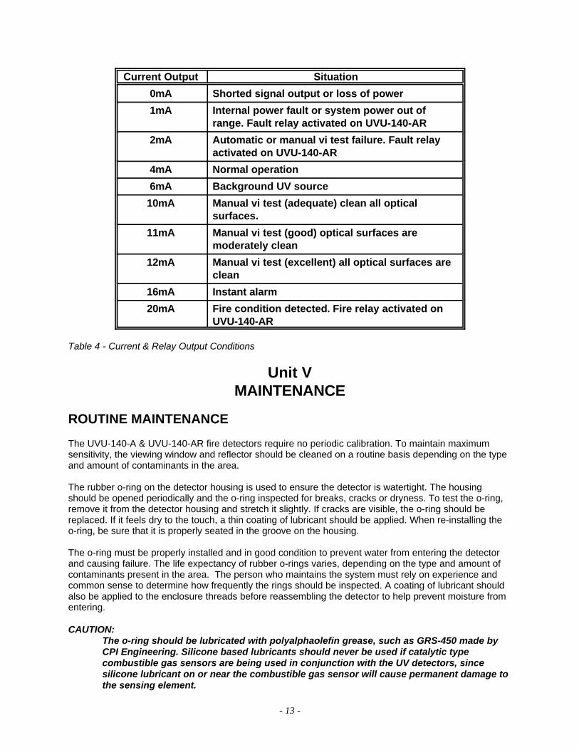
The 4-20mA DC current output transmits system information to other devices. The current output canonly be wired for non-isolated operation. The current output can have a maximum external loopresistance of 600 Ohms at 10.5 to 32Vdc. Table 4 shows the current output levels for various conditions.
- 13 -
Current Output Situation
0mA Shorted signal output or loss of power
1mA Internal power fault or system power out ofrange. Fault relay activated on UVU-140-AR
2mA Automatic or manual vi test failure. Fault relayactivated on UVU-140-AR
4mA Normal operation
6mA Background UV source
10mA Manual vi test (adequate) clean all opticalsurfaces.
11mA Manual vi test (good) optical surfaces aremoderately clean
12mA Manual vi test (excellent) all optical surfaces areclean
16mA Instant alarm
20mA Fire condition detected. Fire relay activated on UVU-140-AR
Table 4 - Current & Relay Output Conditions
Unit VMAINTENANCE
ROUTINE MAINTENANCE
The UVU-140-A & UVU-140-AR fire detectors require no periodic calibration. To maintain maximumsensitivity, the viewing window and reflector should be cleaned on a routine basis depending on the typeand amount of contaminants in the area.
The rubber o-ring on the detector housing is used to ensure the detector is watertight. The housingshould be opened periodically and the o-ring inspected for breaks, cracks or dryness. To test the o-ring,remove it from the detector housing and stretch it slightly. If cracks are visible, the o-ring should bereplaced. If it feels dry to the touch, a thin coating of lubricant should be applied. When re-installing theo-ring, be sure that it is properly seated in the groove on the housing.
The o-ring must be properly installed and in good condition to prevent water from entering the detectorand causing failure. The life expectancy of rubber o-rings varies, depending on the type and amount ofcontaminants present in the area. The person who maintains the system must rely on experience andcommon sense to determine how frequently the rings should be inspected. A coating of lubricant shouldalso be applied to the enclosure threads before reassembling the detector to help prevent moisture fromentering.
CAUTION:The o-ring should be lubricated with polyalphaolefin grease, such as GRS-450 made byCPI Engineering. Silicone based lubricants should never be used if catalytic typecombustible gas sensors are being used in conjunction with the UV detectors, sincesilicone lubricant on or near the combustible gas sensor will cause permanent damage tothe sensing element.

- 14 -
TROUBLESHOOTING
The automatic vi (visual integrity) feature continuously checks the detector for correct response. If aproblem is detected, Table 4 shows the current output levels for various situations.
CLEANING VIEWING WINDOW AND REFLECTOR
When cleaning the viewing window and reflector use a clean, lint free cloth and the cleaning solutionprovided with the detector. Use only recommended cleaning solutions, as some cleaners can leave aresidue that can block UV radiation.
REPOSITIONING vi ADJUSTMENT ALLEN SCREW
The UV sensor module has an adjustable Allen Screw. This adjustable Allen Screw controls the amountof light released from the vi source during visual integrity testing. To increase the amount of UV lightreleased, turn the Allen Screw counter-clockwise, this will open the orifice and allow more light to passthrough. An ideal setting with a clean lens and reflector would yield an analog output of 12mA during themanual vi test, which represents an excellent response level when performing a manual vi check.
DEVICE REPAIR AND RETURN
The UVU-140-A and UVU-140-AR fire detectors are not designed to be repaired by the customer in thefield. If a problem should develop, first carefully check for proper wiring and programming. If it isdetermined that the problem is caused by an electrical malfunction, the unit must be returned to thefactory for repair.
Net Safety Monitoring Inc. encourages its distributors to make advance replacement units available tothe user during the warranty period. This allows Net Safety Monitoring Inc. to take time to repair the unitcompletely while users keep their operations running with the advance replacement unit.
Prior to returning items, contact the nearest distribution office so that an RMI (Return MaterialIdentification) number can be assigned. A written statement describing the malfunction must accompanythe returned item to simplify finding the cause of the failure and reduce the time and cost of the repair.Pack the item to protect it from damage and use an anti-static bag or aluminum-backed cardboard asprotection from electrostatic discharge.
- I -
Appendix A
Net Safety Monitoring Inc.Electrostatic Sensitive Device Handling Procedure
With the trend toward increasingly widespread use of microprocessors and a wide variety ofother electrostatic sensitive semiconductor devices, the need for careful handling of equipmentcontaining these devices deserves more attention than it has received in the past.
Electrostatic damage can occur in several ways. The most familiar is by physical contact.Touching an object causes a discharge of electrostatic energy that has built up on the skin. Ifthe charge is of sufficient magnitude, a spark will also be visible. This voltage is often morethan enough to damage some electronic components. Some devices can be damaged withoutany physical contact. Exposure to an electric field can cause damage if the electric fieldexceeds the dielectric breakdown voltage of the capacitive elements within the device.
In some cases, permanent damage is instantaneous and an immediate malfunction is realized.Often, however, the symptoms are not immediately observed. Performance may be marginalor even seemingly normal for an indefinite period of time, followed by a sudden and mysteriousfailure.
Damage caused by electrostatic discharge can be virtually eliminated if the equipment ishandled only in a static safeguarded work area and if it is transported in a package orcontainer that will render the necessary protection against static electricity. Net SafetyMonitoring Inc. modules that might be damaged by static electricity are carefully wrapped in astatic protective material before being packaged. Foam packaging blocks are also treated withan anti-static agent. If it should ever become necessary to return the module, it is highlyrecommended that it be carefully packaged in the original carton and static protectivewrapping.
Since a static safeguarded work area is usually impractical in most field installations, cautionshould be exercised to handle the module by its metal shields, taking care not to touchelectronic components or terminals.
In general, always exercise all of the accepted and proven precautions that are normallyobserved when handling electrostatic sensitive devices.
A warning label is placed on the packaging, identifying those units that use electrostaticsensitive semiconductor devices.
*Published in Accordancewith E1A standard 471

- II -
Appendix B
Common Ultra-Violet Absorbing Gases
Since the UVU -140-A & UVU-140-AR fire detectors are designed to detect fires by respondingto the ultra-violet (UV) radiation they emit, it is very important to be aware of UV absorbinggases that may be present between the detector and the sources of potential fires. Smallconcentrations of these types of gases may not absorb enough UV radiation to cause aproblem, but when higher concentrations of these gases are present the detectors maybecome blind as not enough ultra-violet radiation can reach them to activate an alarm. Movingdetectors closer to the probable source of fire and increasing the sensitivity of the detector canhelp to overcome this problem in some cases. Following is a list of common UV absorbinggases:
AcetaldehydeAcetoneAcrylonitrileEthyl AcrylateMethyl AcrylateEthanolAmmoniaAnilineBenzene1,3 Butadiene2-ButanoneButylamineChlorobenzene1-Chloro-1-NitropropaneChloropreneCumeneCyclopentadieneO-DichlorobenzeneP-Dichlorobenzene
Methyl MethacrylateAlpha-MethylstyreneNaphthaleneNitroethaneNitrobenzeneNitromethane1-Nitropropane2-Nitropropane2-PentanonePhenolPhenyl Clycide EtherPyridineHydrogen SulfideStyreneTetrachloroethyleneTolueneTrichloroethyleneVinyl TolueneXylene
- III -
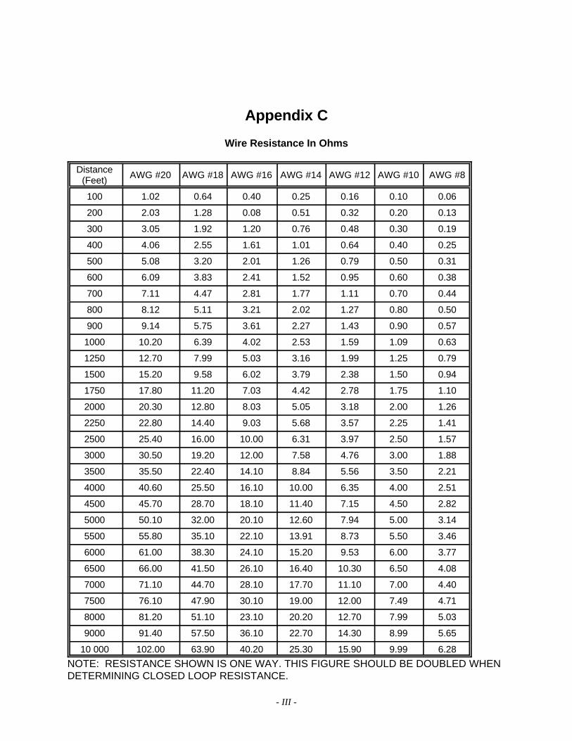
Appendix C
Wire Resistance In Ohms
Distance(Feet) AWG #20 AWG #18 AWG #16 AWG #14 AWG #12 AWG #10 AWG #8
100 1.02 0.64 0.40 0.25 0.16 0.10 0.06
200 2.03 1.28 0.08 0.51 0.32 0.20 0.13
300 3.05 1.92 1.20 0.76 0.48 0.30 0.19
400 4.06 2.55 1.61 1.01 0.64 0.40 0.25
500 5.08 3.20 2.01 1.26 0.79 0.50 0.31
600 6.09 3.83 2.41 1.52 0.95 0.60 0.38
700 7.11 4.47 2.81 1.77 1.11 0.70 0.44
800 8.12 5.11 3.21 2.02 1.27 0.80 0.50
900 9.14 5.75 3.61 2.27 1.43 0.90 0.57
1000 10.20 6.39 4.02 2.53 1.59 1.09 0.63
1250 12.70 7.99 5.03 3.16 1.99 1.25 0.79
1500 15.20 9.58 6.02 3.79 2.38 1.50 0.94
1750 17.80 11.20 7.03 4.42 2.78 1.75 1.10
2000 20.30 12.80 8.03 5.05 3.18 2.00 1.26
2250 22.80 14.40 9.03 5.68 3.57 2.25 1.41
2500 25.40 16.00 10.00 6.31 3.97 2.50 1.57
3000 30.50 19.20 12.00 7.58 4.76 3.00 1.88
3500 35.50 22.40 14.10 8.84 5.56 3.50 2.21
4000 40.60 25.50 16.10 10.00 6.35 4.00 2.51
4500 45.70 28.70 18.10 11.40 7.15 4.50 2.82
5000 50.10 32.00 20.10 12.60 7.94 5.00 3.14
5500 55.80 35.10 22.10 13.91 8.73 5.50 3.46
6000 61.00 38.30 24.10 15.20 9.53 6.00 3.77
6500 66.00 41.50 26.10 16.40 10.30 6.50 4.08
7000 71.10 44.70 28.10 17.70 11.10 7.00 4.40
7500 76.10 47.90 30.10 19.00 12.00 7.49 4.71
8000 81.20 51.10 23.10 20.20 12.70 7.99 5.03
9000 91.40 57.50 36.10 22.70 14.30 8.99 5.65
10 000 102.00 63.90 40.20 25.30 15.90 9.99 6.28
NOTE: RESISTANCE SHOWN IS ONE WAY. THIS FIGURE SHOULD BE DOUBLED WHENDETERMINING CLOSED LOOP RESISTANCE.


- III -
DISTRIBUTED BY:
2711 39 Avenue NECalgary, Alberta, Canada, T1Y 4T8


![UVU English 1010 Syllabus [Spring 2012]](https://static.fdocuments.us/doc/165x107/549dc263ac795929768b45a7/uvu-english-1010-syllabus-spring-2012.jpg)


