![UVU English 1010 Syllabus [Spring 2012]](https://static.fdocuments.us/doc/165x107/549dc263ac795929768b45a7/uvu-english-1010-syllabus-spring-2012.jpg)
UVU Computer Engineering Capstone Project Autonomous ...
16
UVU Computer Engineering Capstone Project Autonomous Robotic Hexapod with Wireless Transmitter Spring 2020 Project Sponsor: Student Justin Limb Faculty Advisor: Dr. Afsaneh Minaie Abstract The purpose of this project was to create a mechatronics system that incorporates computer programming, applied electrical theory, and dynamic mechanical design. The same design principles applied to complex robots used in industry have been implemented in this simplistic robot with the use of feedback control to sense its surroundings, process data, and make decisions for determining its output. The legs of this hexapod include three rotating joints that have been sourced with sensors embedded in the feet to detect contact with the ground. In addition, this hexapod is equipped with a moving tail, 3-axis moving head, functioning mandibles with pressure and range sensors, eyes with PIR sensors to detect motion of threats, and a color sensor to allow its external shell to camouflage with its environment via RGB LED’s. Internally, there are sensors to monitor servo thermal overload, battery voltage and amperage draw. The software development for this project was created on STM32 Workbench (Eclipse IDE) and utilizes libraries imported from STM32CubeMX. The libraries act as an interface between the application level and the hardware level to interact with the processor and registers. Libraries for the communication protocol of all the peripherals such as I2C, UART, etc. were imported and utilized with the hardware of this project. This hexapod robot functions by one of two modes: manual-mode by means of a Bluetooth transmitter with navigating buttons, and auto-mode with the aid of sensors to navigate its surroundings and defend itself from potential threats.
Transcript of UVU Computer Engineering Capstone Project Autonomous ...
UVU Computer Engineering Capstone
Project
Autonomous Robotic Hexapod with Wireless
Transmitter
Spring 2020
Project Sponsor: Student
Justin Limb
Faculty Advisor: Dr. Afsaneh Minaie
Abstract
The purpose of this project was to create a mechatronics system that incorporates computer
programming, applied electrical theory, and dynamic mechanical design. The same design
principles applied to complex robots used in industry have been implemented in this simplistic
robot with the use of feedback control to sense its surroundings, process data, and make
decisions for determining its output.
The legs of this hexapod include three rotating joints that have been sourced with sensors
embedded in the feet to detect contact with the ground. In addition, this hexapod is equipped
with a moving tail, 3-axis moving head, functioning mandibles with pressure and range sensors,
eyes with PIR sensors to detect motion of threats, and a color sensor to allow its external shell to
camouflage with its environment via RGB LED’s. Internally, there are sensors to monitor servo
thermal overload, battery voltage and amperage draw.
The software development for this project was created on STM32 Workbench (Eclipse IDE) and
utilizes libraries imported from STM32CubeMX. The libraries act as an interface between the
application level and the hardware level to interact with the processor and registers. Libraries for
the communication protocol of all the peripherals such as I2C, UART, etc. were imported and
utilized with the hardware of this project.
This hexapod robot functions by one of two modes: manual-mode by means of a Bluetooth
transmitter with navigating buttons, and auto-mode with the aid of sensors to navigate its
surroundings and defend itself from potential threats.
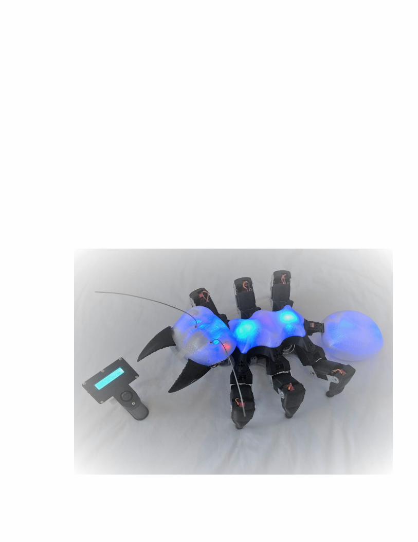
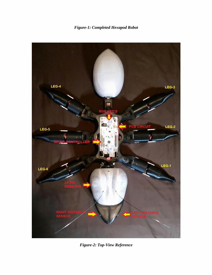
Figure-1: Completed Hexapod Robot
Figure-2: Top-View Reference
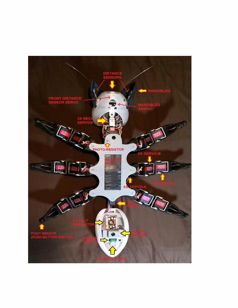
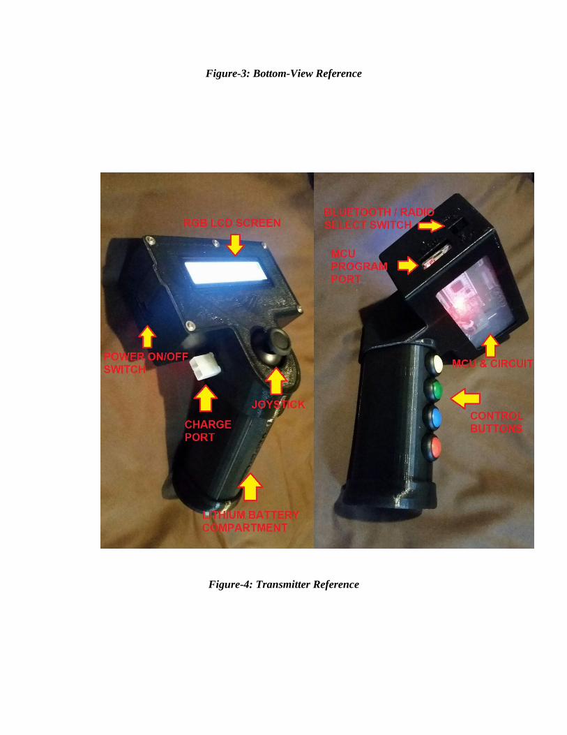
Figure-3: Bottom-View Reference
Figure-4: Transmitter Reference

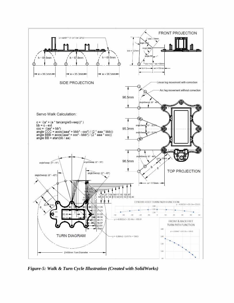
Figure-5: Walk & Turn Cycle Illustration (Created with SolidWorks)
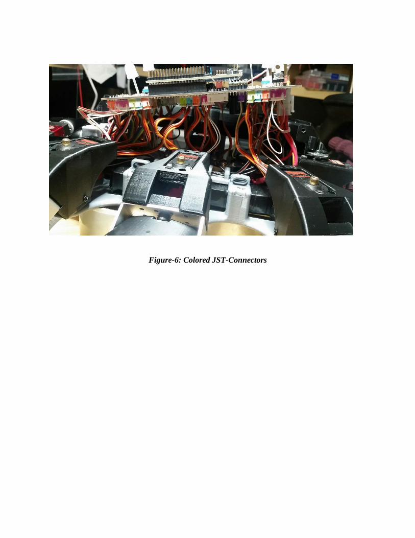
Figure-6: Colored JST-Connectors
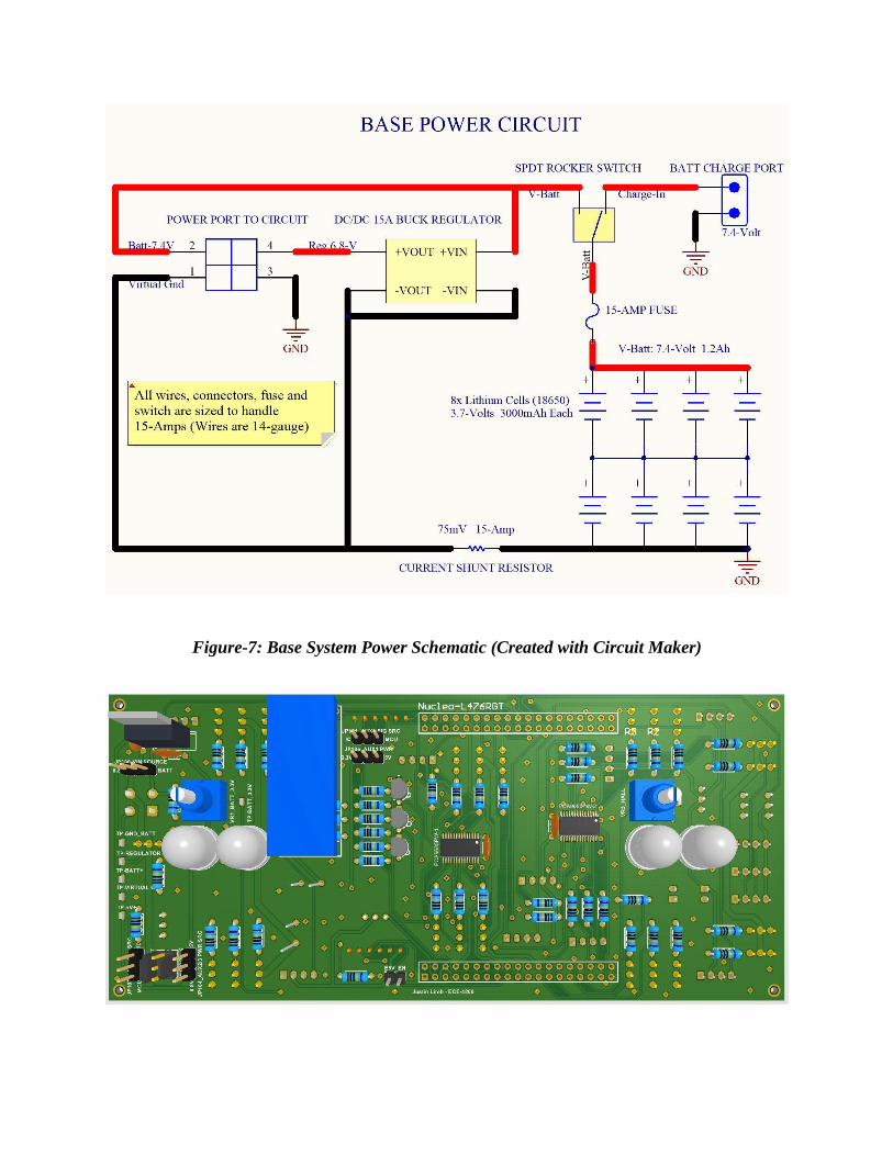
Figure-7: Base System Power Schematic (Created with Circuit Maker)
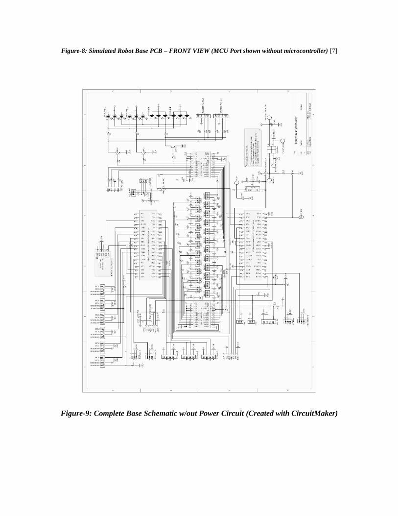
Figure-8: Simulated Robot Base PCB – FRONT VIEW (MCU Port shown without microcontroller) [7]
Figure-9: Complete Base Schematic w/out Power Circuit (Created with CircuitMaker)
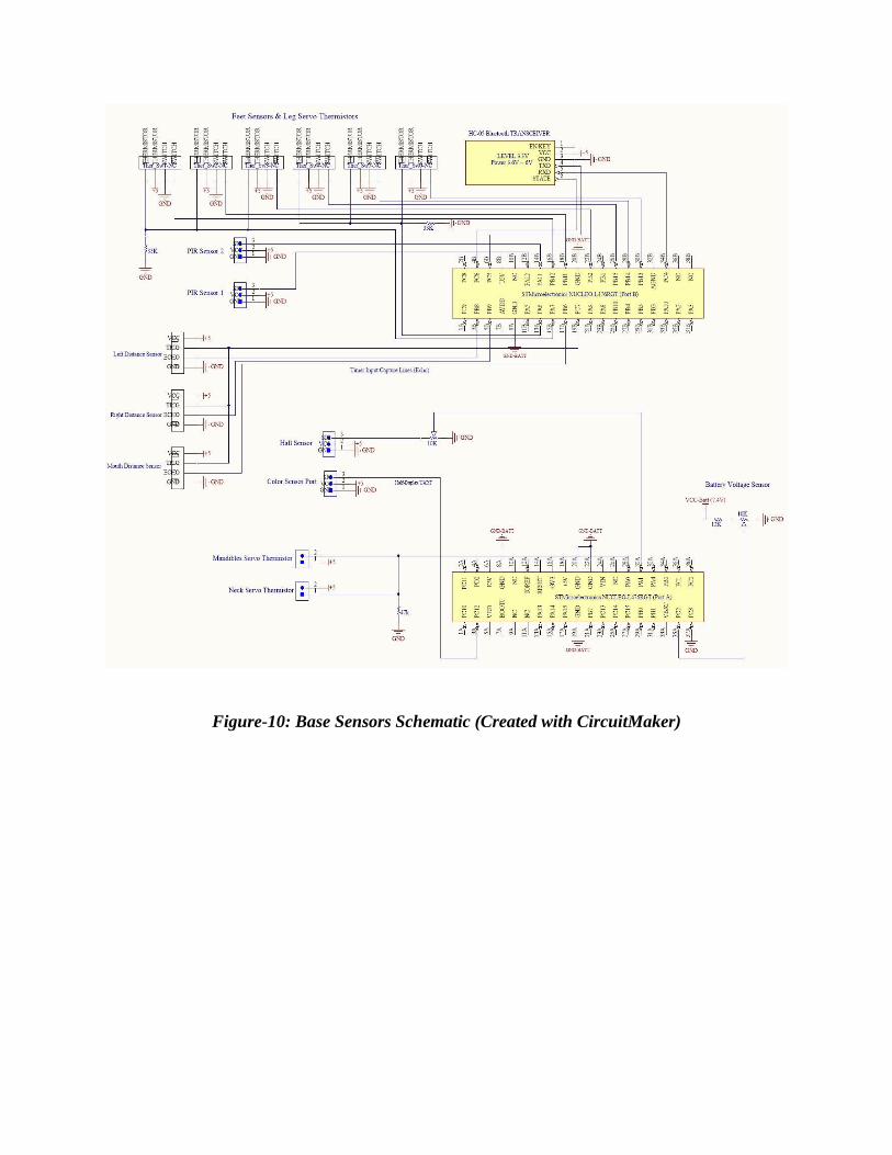
Figure-10: Base Sensors Schematic (Created with CircuitMaker)
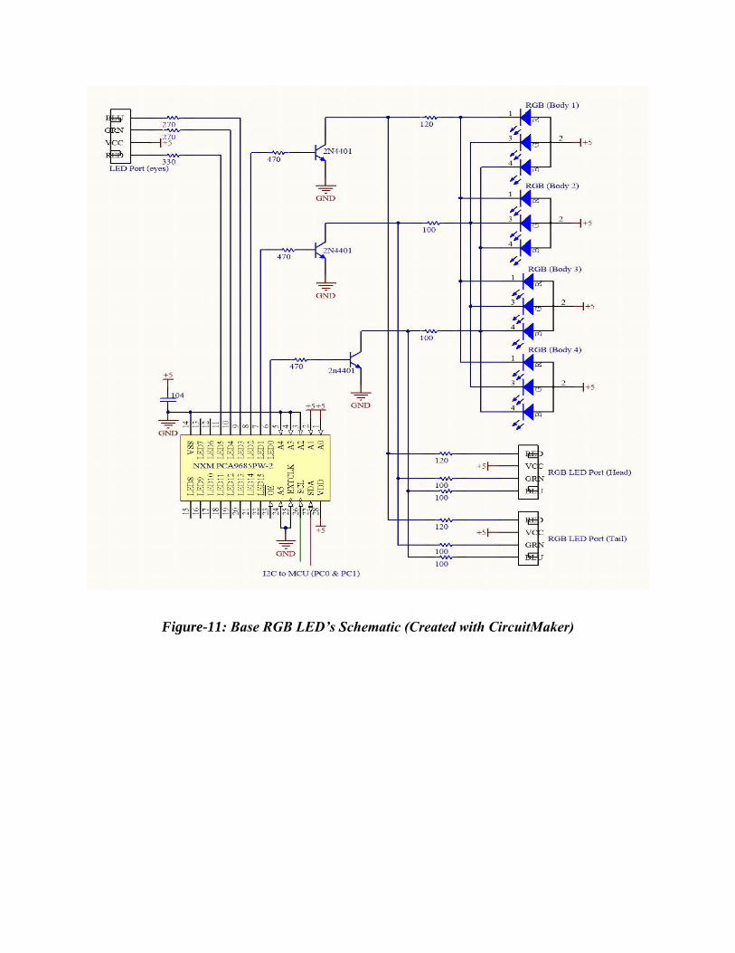
Figure-11: Base RGB LED’s Schematic (Created with CircuitMaker)
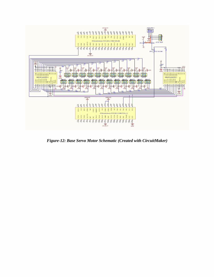
Figure-12: Base Servo Motor Schematic (Created with CircuitMaker)
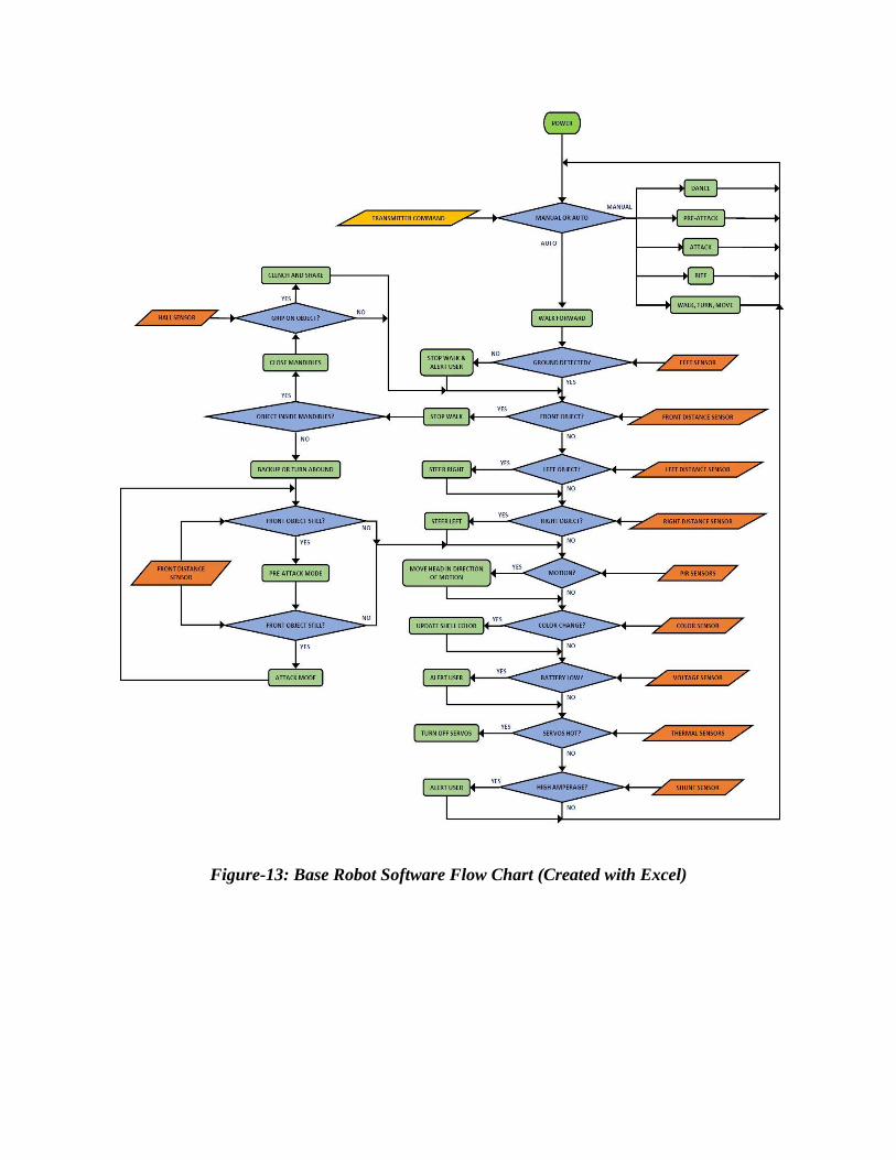
Figure-13: Base Robot Software Flow Chart (Created with Excel)
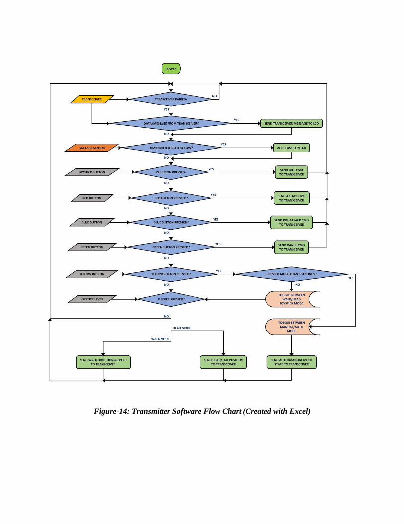
Figure-14: Transmitter Software Flow Chart (Created with Excel)
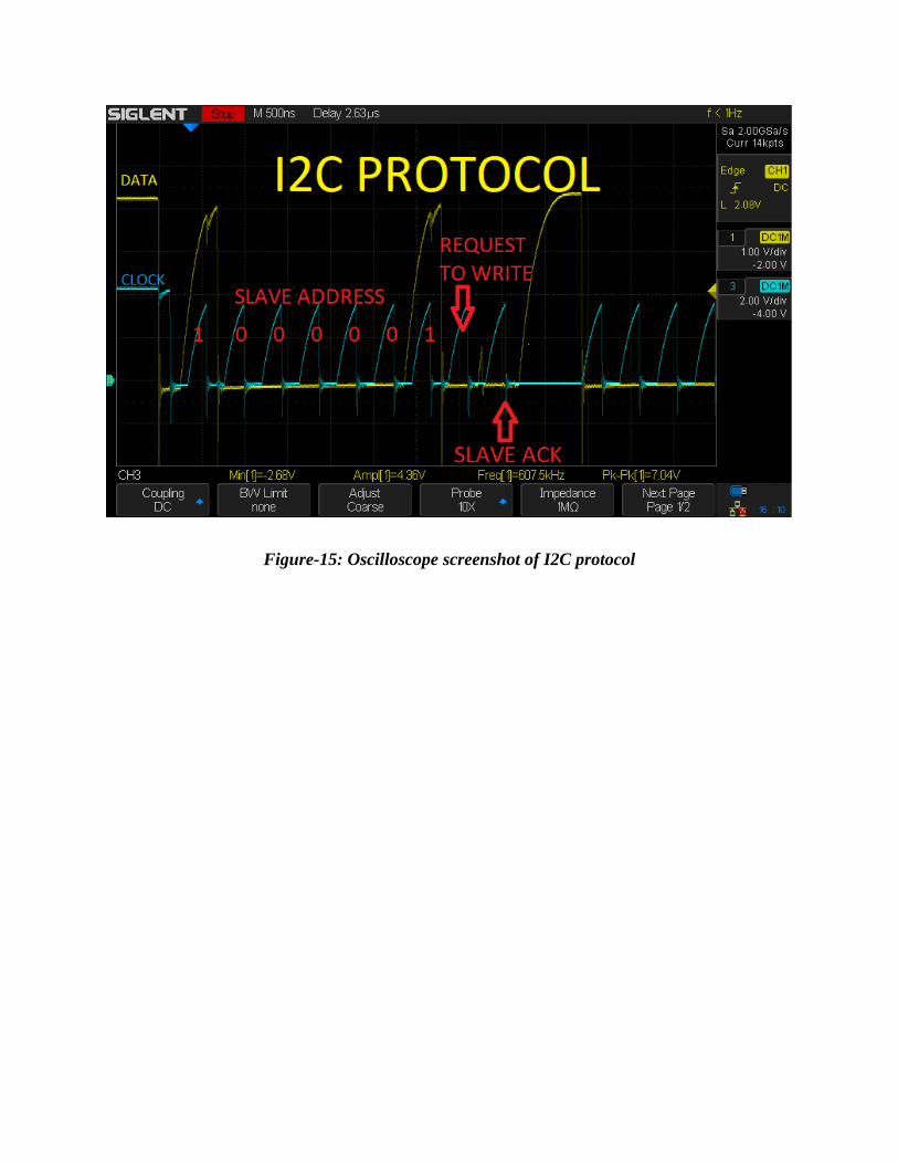
Figure-15: Oscilloscope screenshot of I2C protocol