Model No. KX-NS1000 · Model No. KX-NS1000 Thank you for purchasing this Panasonic product. Please...
1012
PC Programming Manual Pure IP-PBX Model No. KX-NS1000 Thank you for purchasing this Panasonic product. Please read this manual carefully before using this product and save this manual for future use. In particular, be sure to read "1.1.1 For Your Safety (Page 14)" before using this product. KX-NS1000: PCMPR Software File Version 002.10000 or later
Transcript of Model No. KX-NS1000 · Model No. KX-NS1000 Thank you for purchasing this Panasonic product. Please...
PC Programming ManualPure IP-PBX
Model No. KX-NS1000
Thank you for purchasing this Panasonic product.Please read this manual carefully before using this product and save this manual for future use.In particular, be sure to read "1.1.1 For Your Safety (Page 14)" before using this product.
KX-NS1000: PCMPR Software File Version 002.10000 or later

IntroductionAbout this Programming Manual
The PC Programming Manual is designed to serve as a system programming reference for the PanasonicPure IP-PBX. It explains how to programme this PBX using Web Maintenance Console.The PC Programming Manual is divided into the following sections:
Section 1, OverviewProvides an overview of programming the PBX.
Section 2, Introduction of Web Maintenance ConsoleExplains the layout and menus of Web Maintenance Console.
Sections 3 – 27, Web Maintenance Console Operating InstructionsServes as reference operating instructions when using Web Maintenance Console to programme the PBX.
Section 28, AppendixProvides a list of changes from previous software versions of the PBX.
Feature Programming ReferencesProvides a list of all related programming items for each feature.
References Found in the PC Programming ManualPC Programming Manual ReferencesRelated sections of the PC Programming Manual are listed for your reference.
Feature Guide ReferencesThe Feature Guide explains what the PBX can do, as well as how to obtain the most of its many features andfacilities. Sections from the Feature Guide are listed throughout this manual for your reference.
Installation Manual ReferencesThe Installation Manual provides instructions detailing the installation and maintenance of the PBX. Sectionsfrom the Installation Manual are listed throughout this manual for your reference.
Links to Other Pages and ManualsIf you are viewing this manual with a PC, certain items are linked to different sections of this and other PBXmanuals. Click on a link to jump to that section.Linked items include:• Installation Manual References• PC Programming Manual References• Feature Guide References
Trademarks• Microsoft, Outlook, Internet Explorer, Windows and Windows Vista are either registered trademarks or
trademarks of Microsoft Corporation in the United States and/or other countries.• Intel and Intel Core are trademarks of Intel Corporation in the U.S. and other countries.• Mozilla and Firefox are registered trademarks of the Mozilla Foundation.
2 PC Programming Manual
Introduction

• All other trademarks identified herein are the property of their respective owners.• Microsoft product screen shot(s) reprinted with permission from Microsoft Corporation.
Notice• During a long programming session, it is highly recommended that you periodically save the system data
to the Storage Memory Card. If the PBX undergoes a sudden power failure or if the system is reset forsome reason, all the system data in RAM will be lost. However, if system data has been saved to theStorage Memory Card, it can be easily reloaded.
• To save the system data to the Storage Memory Card, (1) click the button on the Home screen of WebMaintenance Console before resetting the PBX or turning off the power, or (2) logout from WebMaintenance Console so that the PBX automatically saves the system data.
NOTES• The contents of this manual apply to PBXs with a certain software version, as indicated on the cover of
this manual. To confirm the software version of your PBX, see How do I confirm the software versionof the PBX or installed cards? in Maintenance Console Software in 2.3 Frequently Asked Questions(FAQ).
• Some optional hardware, software, and features are not available in some countries/areas, or for somePBX models. Please consult your certified Panasonic dealer for more information.
• Product specifications, including text displayed by the software, are subject to change without notice.• In this manual, the suffix of each model number (e.g., KX-NS1000NE) is omitted unless necessary.
PC Programming Manual 3
Introduction

The KX-NS1000UK and KX-NS1000NE are designed to interwork with the:• Analogue Public Switched Telephone Network (PSTN) of European countries• Pan-European Integrated Services Digital Network (ISDN) using ISDN basic rate
access• Pan-European Integrated Services Digital Network (ISDN) using ISDN primary rate
access
Panasonic System Networks Co., Ltd./Panasonic System Networks Company U.K. Ltd. declares thatthe KX-NS1000UK and the KX-NS1000NE are in compliance with the essential requirements and otherrelevant provisions of Radio & Telecommunications Terminal Equipment (R&TTE) Directive 1999/5/EC.Declarations of Conformity for the relevant Panasonic products described in this manual are availablefor download by visiting:
http://www.doc.panasonic.de
Contact to Authorised Representative:Panasonic Testing CentrePanasonic Marketing Europe GmbHWinsbergring 15, 22525 Hamburg, Germany
4 PC Programming Manual
Introduction

Table of Contents1 Overview .................................................................................................131.1 Introduction .....................................................................................................................141.1.1 For Your Safety ..............................................................................................................141.1.2 Introduction .....................................................................................................................161.1.3 Entering Characters .......................................................................................................171.2 PC Programming .............................................................................................................211.2.1 Starting Web Maintenance Console ...............................................................................211.2.2 PC Programming Using Off-line Mode ...........................................................................251.2.2.1 Editing and Printing Terminal Labels in Off-line Mode ................................................301.2.3 PBX Configuration Types ...............................................................................................311.2.3.1 One-look Networking Survivability ...............................................................................33
2 Introduction of Web Maintenance Console .........................................352.1 Introduction .....................................................................................................................362.1.1 Web Maintenance Console Accounts ............................................................................362.1.2 Access Levels ................................................................................................................382.1.3 Logging in to Web Maintenance Console .......................................................................422.1.4 Easy Setup Wizard .........................................................................................................432.1.5 Software Interface ..........................................................................................................462.1.6 Card Status ....................................................................................................................502.1.7 Extension Number Setting ..............................................................................................512.2 Logout ..............................................................................................................................522.3 Frequently Asked Questions (FAQ) ..............................................................................53
3 Web Maintenance Console Home Screen ............................................633.1 Home Screen ...................................................................................................................643.1.1 Home Screen—Add Site Wizard ....................................................................................67
4 Status ......................................................................................................694.1 Status—Equipment Status .............................................................................................704.1.1 Status—Equipment Status—UPS ..................................................................................704.1.2 Status—Equipment Status—CS Information ..................................................................714.1.3 Status—Equipment Status—PS Information ..................................................................724.1.4 Status—Equipment Status—UM Port status ..................................................................734.1.5 Status—Equipment Status—USB ..................................................................................74
5 System Control .......................................................................................755.1 System Control—Program Update ................................................................................765.1.1 System Control—Program Update—Download Program File ........................................785.1.2 System Control—Program Update—Update Program File ............................................805.1.3 System Control—Program Update—Plug and Update ..................................................825.2 System Control—MOH ....................................................................................................835.2.1 System Control—MOH—Install ......................................................................................835.2.2 System Control—MOH—Delete .....................................................................................845.2.3 System Control—MOH—Status / Backup ......................................................................855.3 System Control—FAX Card ............................................................................................865.4 System Control—System Reset ....................................................................................875.5 System Control—System Shutdown .............................................................................88
6 Tool ..........................................................................................................896.1 Tool—System Data Backup to USB ..............................................................................906.2 Tool—BRI Automatic Configuration ..............................................................................92
PC Programming Manual 5
Table of Contents

6.3 Tool—NDSS Link Data Clear ..........................................................................................936.4 Tool—Call Pickup for My Group ....................................................................................946.5 Tool—Extension List View .............................................................................................956.6 Tool—Import ....................................................................................................................966.7 Tool—Export ..................................................................................................................1016.8 Tool—Screen Customise ..............................................................................................1026.9 Tool—UM Data Backup .................................................................................................1036.9.1 Tool—UM Data Backup—Manual Backup ...................................................................1046.9.2 Tool—UM Data Backup—Scheduled Backup ..............................................................1056.10 Tool—UM Data Restore ................................................................................................1066.11 Tool—UM Backup History ............................................................................................1086.12 Tool—DXDP All OUS .....................................................................................................1096.13 Tool—Contact information ...........................................................................................1106.14 Tool—UT Option Setting ..............................................................................................1116.15 Tool—URL Information .................................................................................................112
7 Utility .....................................................................................................1137.1 Utility—Diagnosis .........................................................................................................1147.1.1 Utility—Diagnosis—Card Diagnosis .............................................................................1147.1.2 Utility—Diagnosis—Ping ..............................................................................................1177.2 Utility—File ....................................................................................................................1187.2.1 Utility—File—File Transfer PC to PBX .........................................................................1187.2.2 Utility—File—File Transfer PBX to PC .........................................................................1197.2.3 Utility—File—File View .................................................................................................1207.2.4 Utility—File—File Delete ..............................................................................................1217.2.5 Utility—File—Message File Transfer PC to PBX ..........................................................1227.2.6 Utility—File—Message File Transfer PBX to PC ..........................................................1237.3 Utility—Log ....................................................................................................................1247.3.1 Utility—Log—Error Log ................................................................................................1247.3.2 Utility—Log—Syslog .....................................................................................................1267.3.3 Utility—Log—Web-MC Event Log ................................................................................1277.3.4 Utility—Log—UM System Log ......................................................................................1287.4 Utility—Monitor/Trace ...................................................................................................1297.4.1 Utility—Monitor/Trace—ISDN/QSIG Protocol Trace ....................................................1297.4.2 Utility—Monitor/Trace—V-IPGW16 Protocol Trace ......................................................1307.4.3 Utility—Monitor/Trace—V-SIPGW16 Protocol Trace ...................................................1317.4.4 Utility—Monitor/Trace—CS Status Monitor ..................................................................1327.4.5 Utility—Monitor/Trace—Fax - Protocol Trace ...............................................................1337.4.6 Utility—Monitor/Trace—Fax - Task sequence Trace ...................................................1347.4.7 Utility—Monitor/Trace—UM System Trace (Internal) ...................................................1357.4.8 Utility—Monitor/Trace—T1/E1 Signalling Bit Monitor ...................................................1367.4.9 Utility—Monitor/Trace—T1/E1 Line Trace ....................................................................1377.5 Utility—Report ...............................................................................................................1387.5.1 Utility—Report—Digital Trunk Error Report ..................................................................1387.5.2 Utility—Report—IP Extension Statistical Information ...................................................1397.5.3 Utility—Report—UM View Reports ...............................................................................1407.5.4 Utility—Report—E-mail Report .....................................................................................1437.6 Utility—Activation Key Installation ..............................................................................1447.7 Utility—Email Notification ............................................................................................1457.7.1 Utility—Email Notification—Alert ..................................................................................1457.7.2 Utility—Email Notification—System Analysis ...............................................................1467.7.3 Utility—Email Notification—Test Email .........................................................................1477.8 Utility—Command .........................................................................................................1487.8.1 Utility—Command—UM Command ..............................................................................1487.9 Utility—UM – System Prompts Customisation ...........................................................149
6 PC Programming Manual
Table of Contents
7.10 Utility—Automatic Two-way Recording ......................................................................1517.10.1 Utility—Automatic Two-way Recording—Supervisor Setting .......................................1517.10.2 Utility—Automatic Two-way Recording—Extension Setting .........................................1527.10.3 Utility—Automatic Two-way Recording—Extension Setting List ..................................1537.10.4 Utility—Automatic Two-way Recording—Maintenance ................................................1567.11 Utility—UM - System Maintenance ..............................................................................1577.12 Utility—CS-Web Connection ........................................................................................158
8 Users .....................................................................................................1598.1 Users—User Profiles ....................................................................................................1608.1.1 Users—User Profiles—Advanced setting .....................................................................1628.2 Users—Add User ...........................................................................................................1678.2.1 Users—Add User—Single User ...................................................................................1678.2.2 Users—Add User—Multiple Users ...............................................................................1718.3 Users—Automatic Two-way Recording ......................................................................1728.3.1 Users—Automatic Two-way Recording—Edit a Recording .........................................1728.3.2 Users—Automatic Two-way Recording—Record List ..................................................173
9 PBX Configuration—[1] Configuration ...............................................1759.1 PBX Configuration—[1-1] Configuration—Slot ..........................................................1769.2 PBX Configuration—[1-1] Configuration—Slot—Summary ......................................1809.3 PBX Configuration—[1-1] Configuration—Slot—Activation Key Status .................1849.4 PBX Configuration—[1-1] Configuration—Slot—System Property ..........................1879.5 PBX Configuration—[1-1] Configuration—Slot—Site Property ................................2019.5.1 PBX Configuration—[1-1] Configuration—Slot—Site Property—Main .........................2019.5.2 PBX Configuration—[1-1] Configuration—Slot—Site Property—FAX Card .................2259.5.3 PBX Configuration—[1-1] Configuration—Slot—Site Property—NSVM ......................2269.6 PBX Configuration—[1-1] Configuration—Slot—UM Card Property ........................2309.7 PBX Configuration—[1-1] Configuration—Slot—UM Port Property .........................2339.8 PBX Configuration—[1-1] Configuration—Slot—Port Property—Port Type
View ................................................................................................................................2349.9 PBX Configuration—[1-1] Configuration—Slot—V-SIPGW—Shelf Property ...........2359.10 PBX Configuration—[1-1] Configuration—Slot—V-SIPGW—Card Property ...........2409.11 PBX Configuration—[1-1] Configuration—Slot—V-SIPGW—Port Property ............2419.12 PBX Configuration—[1-1] Configuration—Slot—V-IPGW16—Shelf Property .........2699.12.1 PBX Configuration—[1-1] Configuration—Slot—V-IPGW16—Shelf Property—GK
Settings ........................................................................................................................2839.12.2 PBX Configuration—[1-1] Configuration—Slot—Shelf Property - Virtual IP Gateway—Hunt
Pattern ..........................................................................................................................2849.13 PBX Configuration—[1-1] Configuration—Slot—V-IPGW16—Port Property ...........2859.14 PBX Configuration—[1-1] Configuration—Slot—V-IPEXT32—Card Property .........2879.15 PBX Configuration—[1-1] Configuration—Slot—V-IPEXT32—Port Property ..........2929.16 PBX Configuration—[1-1] Configuration—Slot—V-SIPEXT32—Card Property ... . . .3039.17 PBX Configuration—[1-1] Configuration—Slot—V-SIPEXT32—Port Property .......3059.18 PBX Configuration—[1-1] Configuration—Slot—V-IPCS4—Card Property .............3099.19 PBX Configuration—[1-1] Configuration—Slot—V-IPCS4—Port Property ..............3139.20 PBX Configuration—[1-1] Configuration—Slot—V-UTEXT32—Card Property .......3189.21 PBX Configuration—[1-1] Configuration—Slot—V-UTEXT32—Port Property ........3219.22 PBX Configuration—[1-1] Configuration—Slot— SLC2 - Card Property .................3359.23 PBX Configuration—[1-1] Configuration—Slot—SLC2 - Port Property ...................3389.24 PBX Configuration—[1-1] Configuration—Slot—Card Property - LCO type ...........3409.25 PBX Configuration—[1-1] Configuration—Slot—Port Property - LCO Port ............3489.26 PBX Configuration—[1-1] Configuration—Slot—Card Property - BRI type/PRI
type .................................................................................................................................3529.27 PBX Configuration—[1-1] Configuration—Slot—Port Property - BRI Port ..............361
PC Programming Manual 7
Table of Contents

9.28 PBX Configuration—[1-1] Configuration—Slot—Port Property - PRI Port ..............3749.29 PBX Configuration—[1-1] Configuration—Slot—Legacy-GW1/Legacy-GW2 ..........3869.29.1 PBX Configuration—[1-1] Configuration—Slot—Legacy-GW1/Legacy-GW2—Card
Property - OPB3 ...........................................................................................................3889.30 PBX Configuration—[1-1] Configuration—Slot—DOORPHONE Card—Card
Property .........................................................................................................................3909.31 PBX Configuration—[1-2] Configuration—Portable Station .....................................3929.32 PBX Configuration—[1-3] Configuration—Option .....................................................3959.33 PBX Configuration—[1-4] Configuration—Clock Priority .........................................3979.34 PBX Configuration—[1-5] Configuration—DSP Resource ........................................3989.34.1 PBX Configuration—[1-5-1] Configuration—DSP Resource—Setting .........................3989.34.1.1 PBX Configuration—[1-5-1] Configuration—DSP Resource—Setting—DSP Resource
Advisor .......................................................................................................................4029.34.2 PBX Configuration—[1-5-2] Configuration—DSP Resource—Usage ..........................403
10 PBX Configuration—[2] System .........................................................40510.1 PBX Configuration—[2-1] System—Date & Time .......................................................40610.1.1 PBX Configuration—[2-1-1] System—Date & Time—Date & Time Setting .................40610.1.2 PBX Configuration—[2-1-2] System—Date & Time—SNTP / Daylight Saving ............40710.1.2.1 PBX Configuration—[2-1-2] System—Date & Time—SNTP / Daylight Saving—Daylight
Saving ........................................................................................................................41010.2 PBX Configuration—[2-2] System—Operator & BGM ...............................................41210.3 PBX Configuration—[2-3] System—Timers & Counters ...........................................41410.4 PBX Configuration—[2-4] System—Week Table ........................................................43210.4.1 PBX Configuration—[2-4] System—Week Table—Time Setting .................................43210.5 PBX Configuration—[2-5] System—Holiday Table ....................................................43510.6 PBX Configuration—[2-6] System—Numbering Plan ................................................43710.6.1 PBX Configuration—[2-6-1] System—Numbering Plan—Main ....................................43710.6.2 PBX Configuration—[2-6-2] System—Numbering Plan—Quick Dial ...........................46510.6.3 PBX Configuration—[2-6-3] System—Numbering Plan—B/NA DND Call
Feature .........................................................................................................................46610.7 PBX Configuration—[2-7] System—Class of Service ................................................46910.7.1 PBX Configuration—[2-7-1] System—Class of Service—COS Settings ......................46910.7.2 PBX Configuration—[2-7-2] System—Class of Service—External Call Block .............48610.7.3 PBX Configuration—[2-7-3] System—Class of Service—Internal Call Block ...............48710.8 PBX Configuration—[2-8] System—Ring Tone Patterns ...........................................48810.8.1 PBX Configuration—[2-8-1] System—Ring Tone Patterns—Call from CO ..................48810.8.2 PBX Configuration—[2-8-2] System—Ring Tone Patterns—Call from
DOORPHONE ..............................................................................................................48910.8.3 PBX Configuration—[2-8-3] System—Ring Tone Patterns—Call from Others ............49010.9 PBX Configuration—[2-9] System—System Options ................................................49210.10 PBX Configuration—[2-10] System—Extension CID Settings ..................................51610.11 PBX Configuration—[2-11] System—Audio Gain ......................................................52010.11.1 PBX Configuration—[2-11-1] System—Audio Gain—Paging/MOH .............................52010.11.2 PBX Configuration—[2-11-2] System—Audio Gain—Card ..........................................522
11 PBX Configuration—[3] Group ...........................................................52311.1 PBX Configuration—[3-1] Group—Trunk Group ........................................................52411.1.1 PBX Configuration—[3-1-1] Group—Trunk Group—TRG Settings ..............................52411.1.2 PBX Configuration—[3-1-2] Group—Trunk Group—Local Access Priority ..................53011.1.3 PBX Configuration—[3-1-3] Group—Trunk Group—Caller ID Modification .................53111.1.4 PBX Configuration—[3-1-4] Group—Trunk Group—Dialling Plan ...............................53611.1.4.1 PBX Configuration—[3-1-4] Group—Trunk Group—Dialling Plan—Auto
Assign ........................................................................................................................53811.1.5 PBX Configuration—[3-1-5] Group—Trunk Group—Charge Rate ...............................539
8 PC Programming Manual
Table of Contents

11.2 PBX Configuration—[3-2] Group—User Group ..........................................................54011.3 PBX Configuration—[3-3] Group—Call Pickup Group ..............................................54111.3.1 PBX Configuration—[3-3] Group—Call Pickup Group—All Setting ..............................54211.4 PBX Configuration—[3-4] Group—Paging Group ......................................................54311.4.1 PBX Configuration—[3-4] Group—Paging Group—All Setting ....................................54511.4.2 PBX Configuration—[3-4] Group—Paging Group—External Pager .............................54611.5 PBX Configuration—[3-5] Group—Incoming Call Distribution Group .....................54711.5.1 PBX Configuration—[3-5-1] Group—Incoming Call Distribution Group—Group
Settings ........................................................................................................................54711.5.1.1 PBX Configuration—[3-5-1] Group—Incoming Call Distribution Group—Group
Settings—Member List ..............................................................................................55911.5.2 PBX Configuration—[3-5-2] Group—Incoming Call Distribution Group—Queuing Time
Table ............................................................................................................................56111.5.3 PBX Configuration—[3-5-3] Group—Incoming Call Distribution
Group—Miscellaneous .................................................................................................56211.6 PBX Configuration—[3-6] Group—Extension Hunting Group ..................................56411.6.1 PBX Configuration—[3-6] Group—Extension Hunting Group—Member List ...............56611.7 PBX Configuration—[3-7] Group—UM Group ............................................................56711.7.1 PBX Configuration—[3-7-1] Group—UM Group—System Settings .............................56711.7.2 PBX Configuration—[3-7-2] Group—UM Group—Unit Settings ...................................56911.7.2.1 PBX Configuration—[3-7-2] Group—UM Group—Unit Settings—Member List ........57111.8 PBX Configuration—[3-8] Group—PS Ring Group ....................................................57311.8.1 PBX Configuration—[3-8] Group—PS Ring Group—Member List ...............................57511.9 PBX Configuration—[3-9] Group—Conference Group ..............................................57611.9.1 PBX Configuration—[3-9] Group—Conference Group—Member List .........................57811.10 PBX Configuration—[3-10] Group—P2P Group .........................................................57911.11 PBX Configuration—[3-11] Group—VM(DPT) Group .................................................58011.11.1 PBX Configuration—[3-11-1] Group—VM(DPT) Group—System Settings ..................58011.11.2 PBX Configuration—[3-11-2] Group—VM(DPT) Group—Unit Settings .......................58111.11.2.1 PBX Configuration—[3-11-2] Group—VM(DPT) Group—Unit Settings—Member
List .............................................................................................................................58211.12 PBX Configuration—[3-12] Group—VM(DTMF) Group ..............................................58311.12.1 PBX Configuration—[3-12-1] Group—VM(DTMF) Group—System Settings ...............58311.12.2 PBX Configuration—[3-12-2] Group—VM(DTMF) Group—Group Settings .................58411.12.2.1 PBX Configuration—[3-12-2] Group—VM(DTMF) Group—Group Settings—Member
List .............................................................................................................................585
12 PBX Configuration—[4] Extension .....................................................58712.1 PBX Configuration—[4-1] Extension—Wired Extension ...........................................58812.1.1 PBX Configuration—[4-1-1] Extension—Wired Extension—Extension Settings ..........58812.1.1.1 PBX Configuration—[4-1-1] Extension—Wired Extension—Extension Settings—CLIP
Generate ....................................................................................................................61712.1.2 PBX Configuration—[4-1-2] Extension—Wired Extension—FWD/DND .......................62012.1.3 PBX Configuration—[4-1-3] Extension—Wired Extension—Speed Dial ......................62112.1.4 PBX Configuration—[4-1-4] Extension—Wired Extension—Flexible Button ................62212.1.4.1 PBX Configuration—[4-1-4] Extension—Wired Extension—Flexible Button—Flexible
button data copy ........................................................................................................63212.1.5 PBX Configuration—[4-1-5] Extension—Wired Extension—PF Button ........................63312.1.6 PBX Configuration—[4-1-6] Extension—Wired Extension—NDSS Link Data -
Send .............................................................................................................................63412.2 PBX Configuration—[4-2] Extension—Portable Station ............................................63512.2.1 PBX Configuration—[4-2-1] Extension—Portable Station—Extension Settings ..........63512.2.1.1 PBX Configuration—[4-2-1] Extension—Portable Station—Extension Settings—CLIP
Generate ....................................................................................................................66112.2.2 PBX Configuration—[4-2-2] Extension—Portable Station—FWD/DND .......................664
PC Programming Manual 9
Table of Contents

12.2.3 PBX Configuration—[4-2-3] Extension—Portable Station—Flexible Button ................66512.2.3.1 PBX Configuration—[4-2-3] Extension—Portable Station—Flexible Button—Flexible
button data copy ........................................................................................................67412.2.4 PBX Configuration—[4-2-4] Extension—Portable Station—NDSS Link Data -
Send .............................................................................................................................67512.3 PBX Configuration—[4-3] Extension—DSS Console .................................................676
13 PBX Configuration—[5] Optional Device ...........................................67713.1 PBX Configuration—[5-1] Optional Device—Doorphone ..........................................67813.2 PBX Configuration—[5-2] Optional Device—External Pager ....................................68113.3 PBX Configuration—[5-3] Optional Device—Voice Message ...................................68213.3.1 PBX Configuration—[5-3-1] Optional Device—Voice Message—DISA System ..........68213.3.2 PBX Configuration—[5-3-2] Optional Device—Voice Message—DISA Message ........68613.4 PBX Configuration—[5-4] Optional Device—External Relay ....................................68813.5 PBX Configuration—[5-5] Optional Device—External Sensor ..................................690
14 PBX Configuration—[6] Feature .........................................................69314.1 PBX Configuration—[6-1] Feature—System Speed Dial ...........................................69414.2 PBX Configuration—[6-2] Feature—Hotel & Charge .................................................69614.3 PBX Configuration—[6-3] Feature—Verification Code ..............................................70514.4 PBX Configuration—[6-4] Feature—Second Dial Tone .............................................70814.5 PBX Configuration—[6-5] Feature—Absent Message ...............................................70914.6 PBX Configuration—[6-6] Feature—Tenant ................................................................710
15 PBX Configuration—[7] TRS ...............................................................71315.1 PBX Configuration—[7-1] TRS—Denied Code ...........................................................71415.2 PBX Configuration—[7-2] TRS—Exception Code ......................................................71515.3 PBX Configuration—[7-3] TRS—Special Carrier ........................................................71615.4 PBX Configuration—[7-4] TRS—Emergency Dial ......................................................71715.5 PBX Configuration—[7-5] TRS—Miscellaneous .........................................................718
16 PBX Configuration—[8] ARS ...............................................................72116.1 PBX Configuration—[8-1] ARS—System Setting .......................................................72216.2 PBX Configuration—[8-2] ARS—Leading Number ....................................................72316.3 PBX Configuration—[8-3] ARS—Routing Plan Time .................................................72516.3.1 PBX Configuration—[8-3] ARS—Routing Plan Time—Time Setting ............................72616.4 PBX Configuration—[8-4] ARS—Routing Plan Priority .............................................72716.5 PBX Configuration—[8-5] ARS—Carrier .....................................................................72816.6 PBX Configuration—[8-6] ARS—Leading Number Exception ..................................73116.7 PBX Configuration—[8-7] ARS—Authorisation Code for TRG .................................732
17 PBX Configuration—[9] Private Network ...........................................73317.1 PBX Configuration—[9-1] Private Network—TIE Table .............................................73417.2 PBX Configuration—[9-2] Private Network—Network Data Transmission ..............73717.3 PBX Configuration—[9-3] Private Network—Network Operator (VoIP) ...................74017.4 PBX Configuration—[9-4] Private Network—NDSS Key Table .................................74217.5 PBX Configuration—[9-5] Private Network—Centralised UM/VM Unit .....................744
18 PBX Configuration—[10] CO & Incoming Call ...................................74518.1 PBX Configuration—[10-1] CO & Incoming Call—CO Line Settings ........................74618.2 PBX Configuration—[10-2] CO & Incoming Call—DIL Table & Port Settings ..........74718.3 PBX Configuration—[10-3] CO & Incoming Call—DDI / DID Table ...........................75318.3.1 PBX Configuration—[10-3] CO & Incoming Call—DDI / DID Table—Automatic
Registration ..................................................................................................................756
10 PC Programming Manual
Table of Contents

18.3.2 PBX Configuration—[10-3] CO & Incoming Call—DDI / DID Table—NameGenerate ......................................................................................................................758
18.4 PBX Configuration—[10-4] CO & Incoming Call—MSN Table ..................................76018.5 PBX Configuration—[10-5] CO & Incoming Call—Miscellaneous ............................765
19 PBX Configuration—[11] Maintenance ..............................................76719.1 PBX Configuration—[11-1] Maintenance—Main ........................................................76819.2 PBX Configuration—[11-2] Maintenance—Air Synchronisation ..............................78219.3 PBX Configuration—[11-3] Maintenance—Power Failure Transfer ..........................786
20 UM Configuration—[1] Mailbox Settings ...........................................78720.1 UM Configuration—[1] Mailbox Settings ....................................................................78820.1.1 UM Configuration—[1-1] Mailbox Settings—Quick Setting ..........................................78820.1.2 UM Configuration—[1-2] Mailbox Settings—Full Setting ..............................................79020.1.3 UM Configuration—[1-3] Mailbox Settings—Auto Configuration ..................................820
21 UM Configuration—[2] Class of Service ............................................82321.1 UM Configuration—[2] Class of Service .....................................................................824
22 UM Configuration—[3] UM Extension / Trunk Service .....................84122.1 UM Configuration—[3-1] UM Extension / Trunk Service—Service Group ...............84222.2 UM Configuration—[3-2] UM Extension / Trunk Service—Port Assignment ...........845
23 UM Configuration—[4] Service Settings ............................................84723.1 UM Configuration—[4-1] Service Settings—Caller ID / PIN Call Routing ................84823.2 UM Configuration—[4-2] Service Settings—Parameters ...........................................85223.3 UM Configuration—[4-3] Service Settings—Custom Service ...................................86123.3.1 UM Configuration—[4-3] Service Settings—Custom Service—Menu & Transfer ........86323.3.2 UM Configuration—[4-3] Service Settings—Custom Service—Date Control ...............86723.3.3 UM Configuration—[4-3] Service Settings—Custom Service—Time Control ..............86923.3.4 UM Configuration—[4-3] Service Settings—Custom Service—Day Control ................87123.3.5 UM Configuration—[4-3] Service Settings—Custom Service—Password ...................87223.4 UM Configuration—[4-4] Service Settings—Holiday Table .......................................875
24 UM Configuration—[5] System Parameters .......................................88124.1 UM Configuration—[5-1] System Parameters—Mailbox Group ................................88224.2 UM Configuration—[5-2] System Parameters—Extension Group ............................88424.3 UM Configuration—[5-3] System Parameters—System Caller Name
Announcement ..............................................................................................................88624.4 UM Configuration—[5-4] System Parameters—Parameters .....................................888
25 UM Configuration—[6] H/W Settings ..................................................91525.1 UM Configuration—[6] H/W Settings ...........................................................................916
26 UM Configuration—[7] System Security ............................................91726.1 UM Configuration—[7] System Security .....................................................................918
27 Network Service ...................................................................................92327.1 Network Service—[1] IP Address/Ports ......................................................................92427.2 Network Service—[2] Server Feature ..........................................................................93027.2.1 Network Service—[2-1] Server Feature—DHCP ..........................................................93027.2.2 Network Service—[2-2] Server Feature—FTP .............................................................93327.2.3 Network Service—[2-4] Server Feature—HTTP ..........................................................93527.2.4 Network Service—[2-5] Server Feature—NTP .............................................................93627.2.5 Network Service—[2-6] Server Feature—SMTP ..........................................................937
PC Programming Manual 11
Table of Contents
27.2.6 Network Service—[2-7] Server Feature—IMAP4 .........................................................94127.3 Network Service—[3] Client Feature ...........................................................................94327.3.1 Network Service—[3-1] Client Feature—FTP ..............................................................94327.3.2 Network Service—[3-2] Client Feature—Syslog ..........................................................94527.3.3 Network Service—[3-3] Client Feature—SNMP Agent ................................................94627.4 Network Service—[4] Other ..........................................................................................95027.4.1 Network Service—[4-1] Other—Security ......................................................................950
28 Appendix ...............................................................................................95128.1 Revision History ............................................................................................................95228.1.1 KX-NS1000 PCMPR Software File Version 002.0xxxx ................................................95228.1.2 KX-NS1000 PCMPR Software File Version 002.1xxxx ................................................954
Feature Programming References ...........................................................955
12 PC Programming Manual
Table of Contents

Section 1
Overview
This section provides an overview of programming thePBX.
PC Programming Manual 13
1.1 Introduction
1.1.1 For Your SafetyTo prevent personal injury and/or damage to property, be sure to observe the following safety precautions.The following symbols classify and describe the level of hazard and injury caused when this unit isoperated or handled improperly.
WARNINGThis notice means that misuse could result in deathor serious injury.
CAUTIONThis notice means that misuse could result in injuryor damage to property.
The following types of symbols are used to classify and describe the type of instructions to beobserved.
This symbol is used to alert users to a specific operating procedure that must not be performed.
This symbol is used to alert users to a specific operating procedure that must be followed inorder to operate the unit safely.
14 PC Programming Manual
1.1.1 For Your Safety
WARNING
• Unplug the PBX from the AC outlet if it emits smoke, an abnormal smell or makes unusual noise. Theseconditions can cause fire or electric shock. Confirm that smoke has stopped and contact an authorisedPanasonic Factory Service Centre.
CAUTION
• Do not remove the Storage Memory Card while power is supplied to the PBX. Doing so may cause thePBX to fail to start when you try to restart the system.
• To the Administrator or Installer regarding account passwords1. Please provide all system passwords to the customer.2. To avoid unauthorised access and possible abuse of the PBX, keep the passwords secret, and inform
the customer of the importance of the passwords, and the possible dangers if they become known toothers.
3. The PBX has no passwords set initially. For security, select an installer password as soon as the PBXsystem is installed at the site.
4. Change the passwords periodically.5. It is strongly recommended that passwords of 10 numbers or characters be used for maximum
protection against unauthorised access.• There is a risk that fraudulent telephone calls will be made if a third party discovers a personal identification
number (PIN) (verification code PIN or extension PIN) of the PBX.The cost of such calls will be billed to the owner/renter of the PBX.To protect the PBX from this kind of fraudulent use, we strongly recommend:a. Keeping PINs secret.b. Selecting complex, random PINs that cannot be easily guessed.c. Changing PINs frequently.
PC Programming Manual 15
1.1.1 For Your Safety

1.1.2 IntroductionThese programming instructions are designed to serve as an overall system programming reference for thePBX. Each feature in the PBX has default settings that can be changed to customise the PBX to yourrequirements. These settings control the functions of the PBX, and changing them is referred to as "systemprogramming".Programming can be performed by system installers, on-site managers, and individual users. However,managers and individual users may only change a limited number of settings. For details, see 2.1.1 WebMaintenance Console Accounts.All features and settings of the PBX can be programmed through system programming with Web MaintenanceConsole. Starting Web Maintenance Console is described in 1.2 PC Programming. Individual systemprogramming items are described from Section 3 Web Maintenance Console Home Screen.
Programming ModesThere are two different modes available for programming using Web Maintenance Console:• On-line Mode
On-line mode allows you to use Web Maintenance Console on a PC that is connected to the PBX to modifythe system data and settings used by the PBX. Settings can be modified and results are displayed in realtime. Modifications to settings change the information in the PBX’s temporary memory (DRAM). To finalisethe changes, you must either save the changes to the PBX’s Storage Memory Card by clicking or logout of Web Maintenance Console by clicking . For details, see Web Maintenance Console Featuresin 2.1.5 Software Interface.
• Off-line ModeOff-line mode allows you to connect to a version of Web Maintenance Console running on your PC. UsingOff-line mode, you can create new system data files and make modifications to system data files storedon your PC, without being connected to the PBX. After you finish configuring settings, they can be savedand uploaded to the PBX, which will update the PBX’s settings. For details, see Uploading ProgrammedSettings to the PBX in 1.2.2 PC Programming Using Off-line Mode.
16 PC Programming Manual
1.1.2 Introduction

1.1.3 Entering CharactersThe characters on a white background below can be used when storing a name, message, password or othertext entry data using a PC. The available characters vary according to the model of PBX.
Table 1 (Standard)
PC Programming Manual 17
1.1.3 Entering Characters

Table 2 (For CE model)
18 PC Programming Manual
1.1.3 Entering Characters

Table 3 (For RU model)
PC Programming Manual 19
1.1.3 Entering Characters

Table 4 (For GR model)
20 PC Programming Manual
1.1.3 Entering Characters

1.2 PC Programming
1.2.1 Starting Web Maintenance ConsoleSystem programming, diagnosis and administration can be performed with a PC using Web MaintenanceConsole. Web Maintenance Console is accessed through a Web browser running on a networked PC.This section describes how to set up and access Web Maintenance Console.
System RequirementsRequired Operating System• Microsoft® Windows® XP, Windows Vista® Business, Windows 7, Windows 7 Professional, Windows 8 or
Windows 8 Professional operating system
Recommended Display Settings• Screen resolution: XGA (1024 ´ 768)• DPI setting: Normal size (96 DPI)
Supported Browsers for use with Web Maintenance Console• Windows Internet Explorer® 8• Windows Internet Explorer 9• Mozilla® Firefox® version 6 or later
Always apply the latest updates to your Web browser software. For details, refer to your Web browser’sdocumentation. Only the browsers and browser versions listed above are supported for use with WebMaintenance Console.
NoteWhen using Windows Internet Explorer, there may be a delay when displaying some screens of WebMaintenance Console. A message may be displayed that reads "Stop running this script?". This messageis automatically displayed when a script takes a long time to complete. If this message is displayed, clickNo to continue using Web Maintenance Console. If you click Yes, you will have to close the browser windowfor Web Maintenance Console and log in again. For information about disabling this prompt, refer to yourWeb browser’s on-line support resources.
Browser Setting RequirementsThe following functions must be enabled in the Web browser’s settings to use Web Maintenance Console:• SSL 3.0• Cookies• JavaScript• The ability to download files• The display of animations• The display of imagesFor details regarding the above settings, refer to your Web browser’s documentation.
PC Specifications (for programming in Off-line mode)The following are recommended specifications for PCs used for programming in Off-line mode. For detailsabout programming in Off-line mode, see 1.2.2 PC Programming Using Off-line Mode.
Recommended Specification
CPU 3.2 GHz Intel® Core™ 2 Duo processor or comparable CPU
PC Programming Manual 21
1.2.1 Starting Web Maintenance Console
Recommended Specification
RAM 2048 MB
Hard Disk 10 GB available space
Copyright for MD5This software uses the Source Code of RSA Data Security, Inc. described in the RFC1321 (MD5Message-Digest Algorithm).
Copyright (C) 1991-2, RSA Data Security, Inc. Created 1991. All rights reserved.
Licence to copy and use this software is granted provided that it is identified as the "RSA Data Security, Inc.MD5 Message-Digest Algorithm" in all material mentioning or referencing this software or this function.
Licence is also granted to make and use derivative works provided that such works are identified as "derivedfrom the RSA Data Security, Inc. MD5 Message-Digest Algorithm" in all material mentioning or referencing thederived work.
RSA Data Security, Inc. makes no representations concerning either the merchantability of this software orthe suitability of this software for any particular purpose. It is provided "as is" without express or implied warrantyof any kind.These notices must be retained in any copies of any part of this documentation and/or software.
PC Connection (On-line Mode)To connect to Web Maintenance Console in On-line mode, both the PC and the PBX must be connected. Theconnection can be made through a local area network (LAN), a virtual private network (VPN), or over theInternet. A PC can also be connected directly to the maintenance port of the PBX.
Note• When connecting to Web Maintenance Console over the Internet, the use of an encrypted
communication method, such as SSL, is strongly recommended. For details, contact your network’sadministrator.
Connecting to Web Maintenance Console (On-line Mode)Below is the procedure for connecting to Web Maintenance Console to programme in On-line mode:1. Connect the PC to the PBX:
• Connect the PBX to a PC with the MNT port and access the PBX directly from the PC.• Connect the PBX to a network with the LAN port and access the PBX from a PC in your LAN or VPN.• Connect the PBX to a network with the LAN port and access the PBX from a PC using an Internet
connection.
Notice• When connecting the PC to the MNT port, if the PC is set to obtain the IP address automatically,
the IP address of the PC will be set to an appropriate IP address to establish a connection to thePBX. For more information about the connection procedure, refer to 5.2 PC Connection in theInstallation Manual.
2. Access Web Maintenance Console:MNT Port connection:
22 PC Programming Manual
1.2.1 Starting Web Maintenance Console
Launch your Web browser and in the address bar, enter one of the following addresses exactly as shown:– 223.0.0.1
or– http://kx-ns1000.
NoteIf entering "http://kx-ns1000.", be sure to include the period at the end as shown.
LAN or VPN connection:Launch your Web browser and input the IP address of the PBX followed by the Web Maintenance Consoleport number into the address bar. The input method will differ according to the PC’s connection to the PBX.The default IP address for the LAN port of the PBX is 192.168.0.101, and the default Web MaintenanceConsole port number is 80. Accordingly, the address to enter to connect to the PBX for the first time willbe as follows (enter the address exactly as shown):http://192.168.0.101
Internet connection (SSL Connection):When the PC is accessing the PBX from a connection over the Internet, the use of SSL is stronglyrecommended. When using an SSL encrypted connection, the default port is 443. The format of the addressto enter to connect to the PBX using an SSL encrypted connection will be as follows:https://xxx.xxx.xxx.xxx:yyy• "xxx.xxx.xxx.xxx" is the IP address of a device that can be accessed from the Internet, such as the
IP address of a network router.• "yyy" is a port number. The network router’s port forwarding settings must be configured so that traffic
arriving at port "yyy" is forwarded to the correct IP address and port of the PBX in the LAN.• Port forwarding settings must specify the IP address and the port number of the network router
("xxx.xxx.xxx.xxx:yyy") to transfer the packets to the PBX in the LAN, so that the packets sent to theglobal IP address and specified port of the router will be transferred to the IP address and specifiedport of the PBX in the LAN.
• Note the usage of "https" instead of "http".• If you connect to Web Maintenance Console using SSL, a security alert window is displayed. Follow
the prompts to install a security certificate. The procedure may vary according to your browser.
Note• The IP address and Web Maintenance Console port number for the PBX can be changed from
their default values. If settings for the LAN port’s IP address or port number have been forgotten,connect using the MNT port connection as described above and confirm the LAN port’s IP addressin 27.1 Network Service—[1] IP Address/Ports—Basic Settings, and the port in 27.2.3 NetworkService—[2-4] Server Feature—HTTP.
• You can also connect to the PBX in On-line mode using the Off-line Web Maintenance ConsoleProgramme Launcher. For details, see Connecting in On-line Mode using the ProgrammeLauncher in 1.2.2 PC Programming Using Off-line Mode.
3. The Web Maintenance Console login screen is displayed. For details about logging in, see 2.1.3 Loggingin to Web Maintenance Console.• If this is the first time the PBX is accessed (i.e., it is in its initialised, factory default state), you must log
in using the Installer level account. Once you log in, the Easy Setup Wizard will launch. For details,see 2.1.4 Easy Setup Wizard.
• If the PBX has been set up using the Easy Setup Wizard, PBX system programming can be performed.To perform programming, enter the login name and password according to your status andauthorisation level. For details about the differences between levels of authorisation, see 2.1.1 WebMaintenance Console Accounts.
PC Programming Manual 23
1.2.1 Starting Web Maintenance Console

4. After you successfully log in to Web Maintenance Console, the Home screen will be displayed andprogramming can be performed. For details about accessing the different features of Web MaintenanceConsole, See 2.1.5 Software Interface.
Connecting to Web Maintenance Console (Off-line Mode)To connect to Web Maintenance Console in Off-line mode, use the New -Offline Mode or Open -OfflineMode operations in the Off-line Web Maintenance Console programme launcher. For details, refer to 1.2.2 PCProgramming Using Off-line Mode.
24 PC Programming Manual
1.2.1 Starting Web Maintenance Console

1.2.2 PC Programming Using Off-line ModePC Programming is performed by connecting to the PBX using Web Maintenance Console, which is also knownas On-line mode. However, as certain programming requires installed cards to be set to out of service (OUS),or requires system settings to be changed, some programming cannot be performed while the PBX is in use.Off-line mode programming is performed using the Off-line version of Web Maintenance Console, which youinstall on your PC.Off-line mode allows you to create new system data files and make modifications to system data files storedon your PC, without being connected to the PBX. The programming changes can be saved and then lateruploaded to the PBX.The following procedures outline how to install and use the Off-line Web Maintenance Console for Off-linemode programming.
InstallationNote
• Be sure to install and use the latest version of "KX-NS1000 Off-line WEB-Maintenance Console".• Before beginning the installation of Off-line Web Maintenance Console, the following software must be
installed on the PC:– Microsoft .NET Framework 2.0– Microsoft .NET Framework 4This software can be downloaded from Microsoft’s online Download Center.
• To install or uninstall the software on a PC running Windows XP Professional, you must be logged inas a user in either the "Administrators" or "Power Users" group.
• To install or uninstall the software on a PC running Windows Vista Business, Windows 7, Windows 7Professional, Windows 8 or Windows 8 Professional, you must be logged in as a user in the"Administrators" group.
1. Copy the "KX-NS1000 Off-line WEB-Maintenance Console" setup file to your PC.2. Double-click the setup file to run the installer.3. Follow the on-screen instructions provided by the installation wizard.
The Programme LauncherAfter Off-line Web Maintenance Console has been installed, you can run the Programme Launcher from theWindows Start menu.
PC Programming Manual 25
1.2.2 PC Programming Using Off-line Mode

Off-line Web Maintenance Console Programme Launcher
NoteOff-line Web Maintenance Console cannot be used when the PBX Web Manager for Unified PCMaintenance Console (for KX-TDA/KX-TDE/KX-NCP PBXs) is running on the PC.To disable the PBX Web Manager:1. In the Unified PC Maintenance Console launcher, click Option®PBX Web Manager.2. Deselect the Enable Web Server check box.3. Click OK.
Starting a New System Data FileYou can start a new session of PBX programming in Off-line mode. You can then programme PBX settings inOff-line Web Maintenance Console and then save them to a file you can later upload to the PBX.
NoteSince selecting this option creates a blank system data file, uploading this file to the PBX will overwrite allprevious settings. Use this function only when necessary.
To create a new system data file1. In the Programme Launcher, click New -Offline Mode. The Off-line Web Maintenance Console login
screen will be displayed in your PC’s Web browser. For details about the login screen, see 2.1.3 Loggingin to Web Maintenance Console.
2. Log in to Off-line Web Maintenance Console using the Installer level account and password to start theEasy Setup Wizard. For details, see 2.1.4 Easy Setup Wizard.
To convert a KX-TDE/KX-NCP’s system data file to KX-NS1000KX-TDE/KX-NCP system data can be converted for use with the KX-NS1000 by using the Database Converter.1. In the Programme Launcher, click Database Converter. The Database Converter screen will be displayed
in your PC.For details, refer to Converting KX-TDE or KX-NCP System Data for Use with the KX-NS1000 in5.3 Starting Web Maintenance Console in the Installation Manual.
Opening an Existing System Data FileThis operation will load a PBX settings system data file from your PC for programming in Off-line mode. Thesystem data file can be a file created earlier using Off-line Web Maintenance Console, or a system data file
26 PC Programming Manual
1.2.2 PC Programming Using Off-line Mode
downloaded from a PBX. You can then programme PBX settings using Off-line Web Maintenance Consoleand then save the settings to a file you can later upload to the PBX.When you use the following procedure to open a system file created using a previous version of the KX-NS1000software, a confirmation screen will be displayed asking whether you want to convert the system data to thelatest software version. Click Yes to convert the data and proceed with Off-line programming.
NoticeOnly system data created using software version 001.10000 or later can be converted this way. Systemdata created using software version 001.00000 cannot be converted.
To open a system data file1. In the Programme Launcher, click Open -Offline Mode.
The Open dialogue box will be displayed.2. Navigate to the folder containing the system data file you want to open.3. Select the file.4. Click Open, and then click OK.
The file will be loaded and the Off-line Web Maintenance Console login screen will be displayed in yourPC’s Web browser. For details about the login screen, see 2.1.3 Logging in to Web MaintenanceConsole.
5. Log in using an account name and password associated with the system data file that was loaded.
NoteUser (User) level accounts cannot be used to log in to Off-line Web Maintenance Console. For details aboutaccount types, refer to 2.1.1 Web Maintenance Console Accounts.
Connecting in On-line Mode using the Programme LauncherYou can also use the Programme Launcher to log in to Web Maintenance Console in On-line mode. You cansave the IP address and port information for each PBX in a profile. This feature is useful when there are multiplePBXs in your network. For details about connecting to the PBX in On-line mode, see Connecting to WebMaintenance Console (On-line Mode) in 1.2.1 Starting Web Maintenance Console.
To connect in On-line mode using the Programme Launcher1. In the Programme Launcher, click Connect -Online Mode.
The Connection dialogue box will be displayed.2. Select a profile from the drop-down list, or enter the IP address and Port manually.3. Click Connect.
The Web Maintenance Console login screen for connecting directly to the PBX in On-line mode will bedisplayed in your PC’s Web browser. For details about the login screen, see 2.1.3 Logging in to WebMaintenance Console.
Editing and Printing Terminal LabelsYou can create and print key label sheets that match the Flexible Button settings and then use the labels onextensions. In the Programme Launcher, click Terminal Label Print. The screen for editing and printing keylabels will be displayed. For details, see 1.2.2.1 Editing and Printing Terminal Labels in Off-line Mode.
OptionsYou can specify the display language of the Programme Launcher, as well as set the web server port numberfor Off-line Web Maintenance Console. In the Programme Launcher, click Options and change the settingsas necessary.Adding Additional LanguagesAdditional display language files may be made available. To add a display language not listed in the languageselection menu, select Additional language, and then click Browse to specify the language file. Afterspecifying a language file, click OK to change to the selected language.
PC Programming Manual 27
1.2.2 PC Programming Using Off-line Mode

VoIP Test ToolClick the VoIP Test Tool button to launch the VoIP Test Tool. This tool is identical to the VoIP Test Toolincluded with the Unified PC Maintenance Console for KX-TDA/KX-TDE/KX-NCP PBXs.
IP Terminal UtilityClick the IP Terminal button to launch the IP Terminal setup utility. This utility is identical to the IP Terminalutility included with the Unified PC Maintenance Console for KX-TDA/KX-TDE/KX-NCP PBXs.
Programming in Off-line ModeOnce you have logged in to Off-line Web Maintenance Console, programming is very similar to On-line mode.The title bar will be coloured differently from when in On-line mode:
When programming in On-line mode:
When programming in Off-line mode:
Some items are not programmable when in Off-line mode, and those items will be greyed out. Some tools andutilities are also not available in Off-line mode. For details, refer to 2.1.2 Access Levels.
Notice• In Off-line mode, changes made in 6.8 Tool—Screen Customise will not be reflected in On-line mode.
This is because these settings are not stored in the system data file (DCSYS).• When you load the system data file to the PBX, you must install any required activation keys in On-line
mode. Activation keys are required for mailboxes. Settings such as mailbox passwords will be clearedif the number of activation keys for mailboxes is insufficient.
Uploading Programmed Settings to the PBXWhen programming in Off-line mode, clicking the icon will open a save dialogue box. Specify a location andfile name for the system data file. This file can then be uploaded to the PBX in On-line mode using the "FileTransfer PC to PBX" utility. For details, refer to 7.2.1 Utility—File—File Transfer PC to PBX.
Notice• If the PC running the Off-line Web Maintenance Console is shut down, the Web browser is closed, or
the user logs out, any changes that have not been saved will be lost. Be sure to regularly save datawhile programming.
• When you upload a system setting file to the PBX, all existing settings on the PBX will be overwrittenwith the settings in the file, including settings you may not want to change. To change only specificsettings in Off-line mode, follow the procedure below:1. Use the "File Transfer PBX to PC" utility in On-line mode to save a file with the PBX’s current
settings. For details, refer to 7.2.2 Utility—File—File Transfer PBX to PC.2. Use the Open -Offline Mode command in the Programme Launcher to load the PBX system file
in Off-line mode.For details, refer to Opening an Existing System Data File above.
3. Perform the desired programming in Off-line mode, and then click the icon to save the modifiedsystem settings to your PC.
28 PC Programming Manual
1.2.2 PC Programming Using Off-line Mode

4. Log in to Web Maintenance Console in On-line mode, and then use the "File Transfer PC toPBX" utility to upload the modified data to the PBX.
• When programming in Off-line mode, be careful when programming the following parameters:– 20.1.2 UM Configuration—[1-2] Mailbox Settings—Full Setting—Mailbox Parameters—
Mailbox Password (Message client)– 20.1.2 UM Configuration—[1-2] Mailbox Settings—Full Setting—Notification
Parameters— E-mail/Text Message Device—Device No. 1, 2, 3—E-mail AddressThese parameters require an activation key (KX-NSU2xx) to function. If these items are programmedin Off-line mode, but the PBX does not have the required activation key installed, the values specifiedfor these parameters will be cleared when the data is uploaded to the PBX.
PC Programming Manual 29
1.2.2 PC Programming Using Off-line Mode

1.2.2.1 Editing and Printing Terminal Labels in Off-line ModeFollow the procedure below to print key label sheets for use with your system’s extensions and DSS consoles.1. In On-line mode, export PBX system data to your PC, and then open the exported data in Off-line mode.
a. In On-line mode, use the File Transfer PBX to PC utility to save your system’s data and settings to yourPC. For details, see 7.2.2 Utility—File—File Transfer PBX to PC.
b. Use the Programme Launcher to open the system data in Off-line mode. For details, see Opening anExisting System Data File in 1.2.2 PC Programming Using Off-line Mode.
2. In Off-line mode, export the key settings to a CSV file.a. After logging in to Off-line Web Maintenance Console, access the screen from which key settings will
be exported:– For extensions: Setup ® PBX Configuration ® Extension ® Wired Extension ® Flexible
Button– For DSS consoles: Setup ® PBX Configuration ® Extension ® DSS Console
b. Click Export, specify a location to save the flexible key settings data, and then click OK.
NoteThe Export button is available only when in Off-line mode.
3. Open the exported CSV data in the Terminal Label Print utility, and then edit the label settings as necessary.a. In the Programme Launcher, click Terminal Label Print.b. Select Open. Specify the exported CSV file in the dialogue that is displayed, and then click OK.c. Edit the following settings as necessary:
Label Specifies the label that will be printed next to the correspondingbutton. (Max. 20 characters)
Colour of Font Specifies the colour used for the label text for the correspondingbutton. Click Choose to select a colour.
Colour of Background Specifies the colour used for the label background for thecorresponding button. Click Choose to select a colour.
Font Size Specifies the size of the font on the label for the correspondingbutton. (Size value range: 4–15)
Telephone Type Specifies the model number of the telephone to determine the sizeand shape of the label template.
4. Once the settings have been configured, click Key Label Print on the settings screen. Follow the KeyLabel Print Wizard to print the key labels or to output the data as a PDF file.
30 PC Programming Manual
1.2.2 PC Programming Using Off-line Mode

1.2.3 PBX Configuration TypesOne-look Network ConfigurationMultiple KX-NS1000 PBXs can be connected together in a configuration called a One-look network. OneKX-NS1000 PBX serves as the Master unit, and other KX-NS1000 PBXs connect to the Master unit as Slaveunits. Slave unit PBXs receive settings and operation instructions from the Master unit PBX. With thisconfiguration, it is easy to make network-wide changes by performing programming at only one PBX.
One-look Network Data TypesThe data that is set when programming a One-look network using Web Maintenance Console is divided intothree categories: global data, local data, and connection data. The kind of data being programmed affects howthe programming is performed.
Data Type Description
Global Data Global data is related to the function of the PBX network as a whole. These settingsare unified network-wide, including extension and calling configurations.
Local Data Local data is related to the settings and functions of each Slave unit PBX. Localdata includes UM configuration settings and network settings.
ConnectionData
Connection data includes setting information for connecting the Master unit toSlave units in the One-look network.
Details for Master units and Slave units are as follows:
ConfigurationType Description
Master Unit This is the central PBX of a One-look network of KX-NS1000 PBXs. All PBXs in aOne-look network can be programmed by logging in to the Master unit via WebMaintenance Console. Both the global settings (settings that apply to all PBXs)and local settings (settings that apply only to a single Slave unit PBX) of theOne-look network can be programmed in one session. Slave units can also beregistered to the Master unit and then configured from the Master unit.If the Master unit is set to out of service (OUS) for maintenance or due to a problem,the One-look network cannot be used until the Master unit is returned to in service(INS) status.
NoteWhen a single KX-NS1000 is used in a stand-alone configuration or othernetworking configuration, for programming purposes it still must be set as theMaster unit.
Slave Unit Slave units receive programming information from the Master unit for allsystem-wide functions, such as extension information and call handling. EachSlave unit also contains local data programming settings, but these local settingsare still specified using the Master unit. When you log in to a Slave unit, you mayview all global data settings, but only that Slave unit’s local data and connectiondata may be viewed. The only setting data that can be specified using a Slave unitis connection data.If a Slave unit is set to OUS, its resources cannot be used but otherwise theOne-look network will still function. The resources of the OUS Slave unit may beused again when it is returned to INS status.
PC Programming Manual 31
1.2.3 PBX Configuration Types
Stand-alone and Other Networking ConfigurationsA KX-NS1000 PBX can be used as a single stand-alone unit, without connecting to other KX-NS1000 PBXsin a One-look network. Programming is still performed by logging in to the PBX using Web MaintenanceConsole. A KX-NS1000 PBX (including the Master unit of a One-look network) can also connect to other PBXsusing standards such as H.323. For details about other networking configurations, refer to 4.2.2 NetworkType Comparison in the Feature Guide.
32 PC Programming Manual
1.2.3 PBX Configuration Types

1.2.3.1 One-look Networking SurvivabilityA One-look network can be configured so that even if a site’s main PBX fails or is otherwise disconnected fromthe network, operation of the One-look Network as a whole continues. One-look Networking Survivabilityprovides the following features:• Backup Master mode
A Slave unit can be designated as a Backup Master unit. When the Master unit goes offline, the Slave unitswill detect the change in status. The designated Slave unit will switch to Backup Master mode, and theother Slave units will use the Backup Master unit as the Master unit.
• Isolated modeIf no PBX is designated as the Backup Master unit, or if the Backup Master unit also goes offline, Slaveunits will operate in Isolated mode if they are set to do so. In Isolated mode, each PBX will provide serviceto the extensions registered to it and for the trunk lines connected to it.
• Automatic Rerouting to Secondary PBXIf the unit to which an IP extension (e.g., IP-PT or SIP extension) is connected fails, the extension canautomatically switch its connection to a secondary PBX.
• UM Group FailoverWhen a PBX goes offline, incoming calls routed to the UM group of the PBX can be automatically redirectedto another PBX’s UM group.
For more information about One-look Networking Survivability and programming required for each aspect ofnetwork survivability, refer to 4.2.3 One-look Networking Survivability in the Feature Guide.
PC Programming Manual 33
1.2.3 PBX Configuration Types

34 PC Programming Manual
1.2.3 PBX Configuration Types

Section 2
Introduction of Web Maintenance Console
This section serves as reference operating instructionswhen using Web Maintenance Console to programmethe PBX.
PC Programming Manual 35
2.1 Introduction
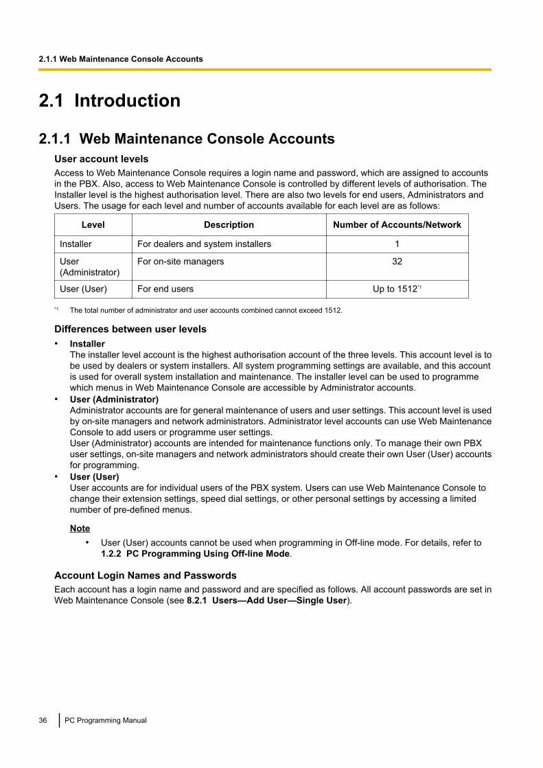
2.1.1 Web Maintenance Console AccountsUser account levelsAccess to Web Maintenance Console requires a login name and password, which are assigned to accountsin the PBX. Also, access to Web Maintenance Console is controlled by different levels of authorisation. TheInstaller level is the highest authorisation level. There are also two levels for end users, Administrators andUsers. The usage for each level and number of accounts available for each level are as follows:
Level Description Number of Accounts/Network
Installer For dealers and system installers 1
User(Administrator)
For on-site managers 32
User (User) For end users Up to 1512*1
*1 The total number of administrator and user accounts combined cannot exceed 1512.
Differences between user levels• Installer
The installer level account is the highest authorisation account of the three levels. This account level is tobe used by dealers or system installers. All system programming settings are available, and this accountis used for overall system installation and maintenance. The installer level can be used to programmewhich menus in Web Maintenance Console are accessible by Administrator accounts.
• User (Administrator)Administrator accounts are for general maintenance of users and user settings. This account level is usedby on-site managers and network administrators. Administrator level accounts can use Web MaintenanceConsole to add users or programme user settings.User (Administrator) accounts are intended for maintenance functions only. To manage their own PBXuser settings, on-site managers and network administrators should create their own User (User) accountsfor programming.
• User (User)User accounts are for individual users of the PBX system. Users can use Web Maintenance Console tochange their extension settings, speed dial settings, or other personal settings by accessing a limitednumber of pre-defined menus.
Note• User (User) accounts cannot be used when programming in Off-line mode. For details, refer to
1.2.2 PC Programming Using Off-line Mode.
Account Login Names and PasswordsEach account has a login name and password and are specified as follows. All account passwords are set inWeb Maintenance Console (see 8.2.1 Users—Add User—Single User).
36 PC Programming Manual
2.1.1 Web Maintenance Console Accounts
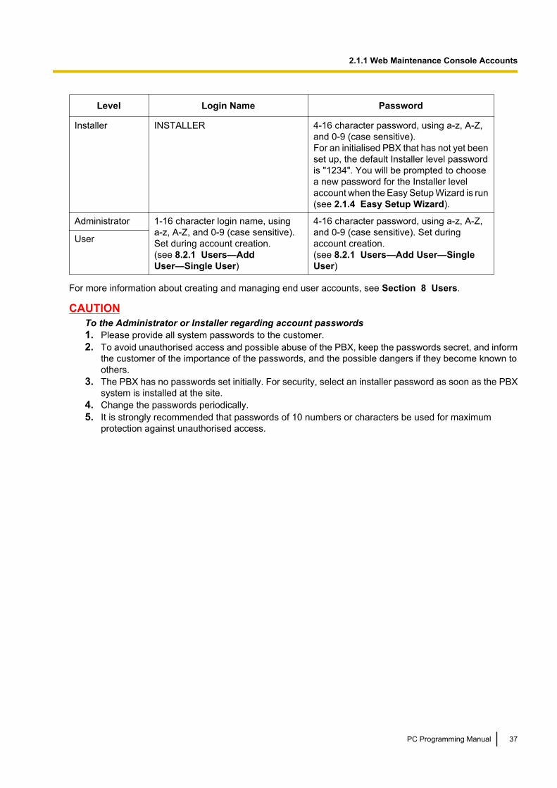
Level Login Name Password
Installer INSTALLER 4-16 character password, using a-z, A-Z,and 0-9 (case sensitive).For an initialised PBX that has not yet beenset up, the default Installer level passwordis "1234". You will be prompted to choosea new password for the Installer levelaccount when the Easy Setup Wizard is run(see 2.1.4 Easy Setup Wizard).
Administrator 1-16 character login name, usinga-z, A-Z, and 0-9 (case sensitive).Set during account creation.(see 8.2.1 Users—AddUser—Single User)
4-16 character password, using a-z, A-Z,and 0-9 (case sensitive). Set duringaccount creation.(see 8.2.1 Users—Add User—SingleUser)
User
For more information about creating and managing end user accounts, see Section 8 Users.
CAUTIONTo the Administrator or Installer regarding account passwords1. Please provide all system passwords to the customer.2. To avoid unauthorised access and possible abuse of the PBX, keep the passwords secret, and inform
the customer of the importance of the passwords, and the possible dangers if they become known toothers.
3. The PBX has no passwords set initially. For security, select an installer password as soon as the PBXsystem is installed at the site.
4. Change the passwords periodically.5. It is strongly recommended that passwords of 10 numbers or characters be used for maximum
protection against unauthorised access.
PC Programming Manual 37
2.1.1 Web Maintenance Console Accounts

2.1.2 Access LevelsAccess to menu options within Web Maintenance Console is restricted depending on the level of the accountand the current programming mode (see Programming Modes in 1.1.2 Introduction). When a menu optionis limited to certain access levels, this is noted in this manual in the initial description of that menu option, forexample:"This option is only available at Installer level."
The options available for each programming mode and access level are shown below.The access levels are abbreviated as follows:U: User (User); A: User (Administrator); I: Installer
NoteUser (User) accounts cannot be used when programming in Off-line mode.
A check mark indicates that the menu option is available for that access level.
Home ScreenMenu Option Off-line On-line
A I U A I
Site Selection ü ü ü ü ü
Add Site ü ü
System Information ü ü ü ü ü
Logout ü ü ü ü ü
ToolMenu Option Off-line On-line
A I U A I
System Data Backup to USB ü ü
BRI Automatic Configuration ü
NDSS Link Data Clear ü
Call Pickup for My Group ü ü
Extension List View ü ü ü ü ü
Import®Feature - Speed Dial and Caller ID ü ü ü ü
Import®Incoming Call - DDI/DID Table ü ü
Import®ARS - Leading Digit ü ü
Import®ARS - Except Code ü ü
Import®ARS - Routing Plan ü ü
Import®Wired Extension ü ü
Import®PS Extension ü ü
Import®Quick Dial ü ü
38 PC Programming Manual
2.1.2 Access Levels

Menu Option Off-line On-line
A I U A I
Import®SIP Extension ü ü
Import®V-IPGW16 GW Settings ü ü
Import®V-IPGW16 DN2IP ü ü
Import®V-SIPGW16 Settings ü ü
Import®V-SIPGW16 Provider ü ü
Export®Feature - Speed Dial and Caller ID ü ü ü ü
Export®Incoming Call - DDI/DID Table ü ü
Export®ARS - Leading Digit ü ü
Export®ARS - Except Code ü ü
Export®ARS - Routing Plan ü ü
Export®Wired Extension ü ü
Export®PS Extension ü ü
Export®Quick Dial ü ü
Export®SIP Extension ü ü
Export®V-IPGW16 GW Settings ü ü
Export®V-IPGW16 DN2IP ü ü
Export®V-SIPGW16 Settings ü ü
Export®V-SIPGW16 Provider ü ü
Screen Customise ü ü
UM Data Backup ü
UM Data Restore ü
UM Backup History ü
DXDP All OUS ü
Contact information ü ü ü ü
UT Option Setting ü ü
URL Information ü ü
UtilityMenu Option Off-line On-line
A I U A I
Diagnosis®Card Diagnosis ü ü
Diagnosis®Ping ü
PC Programming Manual 39
2.1.2 Access Levels

Menu Option Off-line On-line
A I U A I
File Transfer PC to PBX ü
File Transfer PBX to PC ü
File View ü
File Delete ü
Message File Transfer PC to PBX ü
Message File Transfer PBX to PC ü
Error Log ü ü
Syslog ü
Web-MC Event Log ü ü
UM System Log ü
ISDN/QSIG Protocol Trace ü
V-IPGW16 Protocol Trace ü
V-SIPGW16 Protocol Trace ü
CS Status Monitor ü
Fax - Protocol Trace ü
Fax - Task sequence Trace ü
UM System Trace (Internal) ü
T1/E1 Signalling Bit Monitor ü
T1/E1 Line Trace ü
Digital Trunk Error Report ü
IP Extension Statistical Information ü
UM View Reports ü ü
E-mail Report ü ü
Activation Key Installation ü
Email Notification—Alert ü ü
Email Notification—System Analysis ü
Email Notification—Test Email ü
UM Command ü
UM – System Prompts Customisation ü ü
Automatic Two-way Recording ü ü ü ü
UM - System Maintenance ü ü
40 PC Programming Manual
2.1.2 Access Levels

Menu Option Off-line On-line
A I U A I
CS-Web Connection ü ü
PC Programming Manual 41
2.1.2 Access Levels

2.1.3 Logging in to Web Maintenance ConsoleAfter establishing a connection to Web Maintenance Console (see 1.2.1 Starting Web MaintenanceConsole), the login window is displayed, and a login name and password must be entered. If this is the firsttime to log in to Web Maintenance Console, and the PBX is in its initialised, factory default state, you must login using the Installer level account to begin the Easy Setup Wizard (see 2.1.4 Easy Setup Wizard).For information about account names and passwords, see 2.1.1 Web Maintenance Console Accounts.
Login Screen
Login Restrictions• Up to 32 User (User) and User (Administrator) level accounts may log in at one time to Web Maintenance
Console in On-line mode.• Only 1 user may log in using the Installer level account at a time. If someone using the Installer level account
is logged in to Web Maintenance Console and is making changes, and another user logs in using theInstaller level account, the user logging in may override the other logged-in user so that programming canbe performed (a warning screen will be displayed for the user that is about to override the currentlylogged-in user).
• Users can view only menus and setting items they may access according to their account level. For User(Administrator) level accounts, the items that can be viewed can be set by the Installer level account. Fordetails, see 6.8 Tool—Screen Customise.
• If two logged-in users change the same setting, the change made last will be the effective setting.• If a user attempts to log in, but enters an incorrect password three times, the failure is recorded in the error
log of the PBX and the user may not attempt to log in again for a 5-minute period.
42 PC Programming Manual
2.1.3 Logging in to Web Maintenance Console

2.1.4 Easy Setup WizardIn the Easy Setup Wizard, you will configure the mandatory settings required for the PBX. When you log in toWeb Maintenance Console for a PBX that is in its initialised, factory default state, the Easy Setup Wizard forthat PBX will launch automatically.You must log in using the Installer level account name and password.– The Installer level account name is "INSTALLER".– The default Installer level account password is "1234".After logging in, the Easy Setup Wizard welcome screen is displayed. Select a language, and then clickInstall.1. In Location Setting:
a. Select a PBX Type:• Master: Select for a PBX that will be registered as the Master unit of One-look Network. Also select
for a stand-alone PBX that will not be used in a One-look network.• Slave: Select for a PBX that will be registered as a Slave unit of a One-look network. If Slave is
selected, go to step 1-d below.
Note• If the Master unit is located on a different LAN than the Slave unit being registered, the
Slave unit will not be able to automatically detect the Master unit for registration. The IPaddress of the Master unit must be specified. Enter the IP address of the Master unit in Iflocated on different network from Master PBX.
• For information about stand-alone systems and One-look networks, refer to "1.2.3 PBXConfiguration Types".
b. Select a Suffix Code from the drop-down list if Master is selected for PBX Type.c. Select an Area from the drop-down list if Master is selected for PBX Type.d. Click Next.
NoteIf Suffix Code is changed from its default value, a notice about restarting the PBX is displayed. ClickOK to restart the PBX. After the PBX restarts, start Web Maintenance Console again (see1.2.1 Starting Web Maintenance Console). When you start the Easy Setup Wizard again, you willstart from step 2, below.
2. In PBX Setting:a. Specify a Site name if Master was selected for PBX Type in step 1.b. Select a Time Zone from the drop-down list.c. Click the Local Time box and select the date and time from the menu.d. Select the default value of Numbering Plan from below.
– 3 digits Extension Number (This type is recommended for under 8 sites)– 4 digits Extension Number– 3 digits Extension, 4 digits DISA & UM channel
NoticeDepending on the value selected above, the numbering plan of the PBX will vary as follows. Beaware that the default values for floating extension numbers and the number of available UM groupsare different.
PC Programming Manual 43
2.1.4 Easy Setup Wizard

3 digitsExtensionNumber
4 digitsExtensionNumber
3 digitsExtension,4 digitsDISA & UMchannel
Number of UM Group 8 16 9
Extension Number 101–xxx 1001–xxxx 101–xxx
Floating Extension Number
UM Group 500–507 5000–5015 500–508
DISA (1-64) 536–599 5801–5864 5801–5864
TAFAS (Pager) 600 6000 600
ICD Group (1-64) 601–664 6001–6064 601–664
UM Channel (1-2) 508, 509 5101, 5102 5101, 5102
FAX Channel 510 5103 5103
e. Click Next.3. In LAN Setting, the IP addresses for the PBX, DNS server, and DSP cards can be assigned automatically
through a DHCP server or entered manually.
When using a DHCP server:a. Select Obtain an IP address automatically.b. Select Obtain DNS server address automatically.c. Select Obtain DSP IP address automatically.
NoticeThe boxes will turn grey and the IP address information will be assigned automatically. Write downthe address information assigned to the PBX for future reference.
d. Click Next.
When not using a DHCP server:a. Select Use the following IP address.b. Enter an IP address*1, Subnet Mask*2, and Default Gateway*1. (The default gateway may not need to
be specified depending on your network configuration.)c. Select Use the following DNS server address.d. Enter the preferred and alternative DNS IP addresses*1.e. Select Use the following DSP IP address.f. Enter up to 2 IP addresses*1 for each installed DSP card.g. Click Next.
4. In Registration Setting, the IP Terminal Registration Mode and the One Look Networking (TrialActivation Key) can be set.a. Select the IP Terminal Registration Mode:
• Manual: Select this mode to manually register IP terminal information.• Full Automatic: Select this mode to automatically register IP terminal information.• Extension Number Input: Select this mode to automatically register IP terminal information except
its extension number. The extension number can then be registered from the IP telephonemanually.
44 PC Programming Manual
2.1.4 Easy Setup Wizard

Note• Full Automatic and Extension Number Input registration methods may not be available for
certain types of IP terminals. In such cases, select the Manual registration method.• For more information about the IP terminal registration modes, refer to 5.9 Registering IP
Telephones in the Installation Manual.b. For One Look Networking (Trial Activation Key), specify whether to activate the 60-day One-look
Networking Trial Activation Key.– If Active is selected, the 60-day trial will begin when the Easy Setup Wizard is completed.– If Non Active is selected, you will have to activate the trial manually in order to use One-look
Networking Features on a trial basis.c. Click Next.
If Slave has been selected in step 1, the Easy Setup Wizard will finish at this step. If LAN settings havebeen changed from their default values in step 3, you will be prompted to restart the PBX. Click OK torestart the PBX.To add the PBX as a Slave unit PBX to the One-look network, use the Add Site Wizard from the Masterunit PBX’s Home Screen. See 3.1.1 Home Screen—Add Site Wizard.
5. In SNTP / Daylight Saving, enter information for Automatic Time Adjustment and Daylight Saving, andthen click Next.
6. In Maintenance Setting, the Installer password, information for SNMP Setting and SNMP Manager canbe entered.a. Enter a password for the Installer level account in Installer password. Confirm your input in
Re-enter.b. Specify settings for SNMP Setting and SNMP Manager if necessary. If you are unsure of your
network’s SNMP settings, contact your network’s administrator.c. Click Finish.
7. Follow the prompts of the Easy Setup Wizard. After the Easy Setup Wizard is completed, if LAN settingshave been changed from their default values in step 3, you will be prompted to restart the PBX. Click OKto restart the PBX. Otherwise, the login screen will be displayed.
8. Log in with the Installer level account using the password entered during Easy Setup Wizard. The HomeScreen is displayed. You may now begin programming the PBX.
*1 Valid IP address range: "1.0.0.0" to "223.255.255.255"*2 Valid subnet mask address range: "0-255.0-255.0-255.0-255" (except "0.0.0.0" and "255.255.255.255")
Notice• The IP address of the PBX must not be changed once it is set. When an external DHCP server is used
to automatically assign IP addresses, it must be configured to always allocate the same IP address tothe PBX. For details, consult your network administrator.
• If an external DHCP server is in use, it must be able to use a "client identifier" option specified by RFC2131.
PC Programming Manual 45
2.1.4 Easy Setup Wizard

2.1.5 Software InterfaceThis section explains the functions of the various elements of the software interface.
Main WindowWhen you log in to Web Maintenance Console, the main window is displayed. For information about connectingto Web Maintenance Console and logging in, see 1.2.1 Starting Web Maintenance Console.The main window of Web Maintenance Console is divided into several areas, as shown below:
2
31
4
1. Logged in Account LevelThe logged in account level is displayed.
2. Menu ButtonsProvides access to the three main components of Web Maintenance Console:
Button Description
Home Screen
Clicking this button will load the Home Screen. From the Home Screen, you can:• View the status of connected PBXs in the One-look network• Add PBXs to your One-look network• Select a PBX to perform programmingFor more information, see 3.1 Home Screen.
MaintenanceScreen
Clicking this button will display the Maintenance Screen tree view items. From theMaintenance Screen, you can:• Check the status and equipment of the selected PBX• Backup or update PBX system files• Use tools and reports to monitor and analyse system usageFor more information, see Maintenance Screen Tree View Items below.
46 PC Programming Manual
2.1.5 Software Interface
Button Description
Setup Screen
Clicking this button will display the Setup Screen tree view items. From the SetupScreen, you can:• Configure PBX hardware and virtual cards• Programme settings for extensions and call handling• Configure network settings and auxiliary PBX functions• Configure the Unified Messaging (UM) systemFor more information, see Setup Screen Tree View Items below.
3. Web Maintenance Console FeaturesClicking these buttons provides features for Web Maintenance Console, as follows:
Button Description
Save Data
Clicking this button will save any changes made to settings to the Storage MemoryCard. Programming changes that are not saved will be lost if the PBX is reset or isturned off. Changes may also be lost if Web Maintenance Console is suddenlyterminated or the PC running Web Maintenance Console loses power unexpectedly.Be sure to save the data periodically while programming, especially during longprogramming sessions.
SystemInformation
Clicking this button displays the Web Maintenance Console software version,copyright notices, and licences.
NoteLicence information is not displayed when programming in Off-line mode.
Logout
Clicking this button will save any programming changes to the PBX’s Storage MemoryCard and log you out of Web Maintenance Console. For more information, see2.2 Logout.
4. Home Screen/Tree ViewThe Home Screen (shown above) displays the PBX icon view or PBX list view. The information and statusof PBXs in the One-look network can be managed and confirmed. For more information, see 3.1 HomeScreen.When the Maintenance Screen or Setup Screen is selected, the tree view is displayed. The tree view isused to display PBX setting items. Setting items are listed in categories, and by clicking items in the tree,setting items are displayed to the right in the settings programming area. Some tree items havesub-categories with additional options and settings. Clicking a sub-category will open an additional layerof settings. Below is a summary of the tree view menu items for the Setup Screen and the MaintenanceScreen.
Maintenance Screen Tree View Items
Item Primary Functions
Status • Check the status of the PBX’s system hardware• Check the status of PBX equipment (PSs, CSs, UPS, etc.)• Check the status of extensions used by the Unified Messaging systemFor details, see Section 4 Status.
PC Programming Manual 47
2.1.5 Software Interface
Item Primary Functions
System Control • Download and update PBX software files• Manage music on hold (MOH) data• Reset or shutdown the systemFor details, see Section 5 System Control.
Tool • Backup system data to a USB memory device• View a list of PBX extensions• Import and export PBX settings and user information• Backup or restore Unified Messaging dataFor details, see Section 6 Tool.
Utility • Perform tests for PBX cards and network connections• Transfer files between the PBX and a connected PC• View reports, error logs, event logs, and programme update logs• Monitor and trace PBX communications and protocols• Manage activation keysFor details, see Section 7 Utility.
Setup Screen Tree View Items
Item Primary Functions
Users • Manage, view, and add PBX user profiles and account informationFor details, see Section 8 Users.
PBX Configuration • Configure PBX hardware settings for cards, equipment, and networking• Configure network-wide programming such as BGM and Class of Service• Configure dialling features, call routing, and incoming call settings• Configure call logging (SMDR) and other PBX maintenance itemsFor details, see Section 9 PBX Configuration—[1] Configuration toSection 19 PBX Configuration—[11] Maintenance.
UM Configuration • Configure Unified Messaging mailboxes and voice mail subscriber settings• Configure service settings and system parameters• Configure hardware optionsFor details, see Section 20 UM Configuration—[1] Mailbox Settings toSection 26 UM Configuration—[7] System Security.
Network Service • Configure server and client features for the PBX• Configure connections settings and network securityFor details, see Section 27 Network Service.
48 PC Programming Manual
2.1.5 Software Interface

Site Selection MenuWhen you are logged in to the Master unit of a One-look network and you are viewing programming screensin the tree view, a site selection drop-down menu is displayed with each PBX site’s name and ID number. Youcan select a PBX site in the One-look network from the drop-down menu to programme items for that site.
NoteOn some screens, the site selection menu will be inactive. This means that the currently displayedprogramming items are set for the Master unit PBX only, and cannot be set for each Slave unit.
Standard ButtonsThere are standard buttons that are displayed on many screens within the Maintenance Console.The standard buttons are as follows:
Button Function
OK Temporarily implements changes to the system’s memory (DRAM)and closes the current screen.
Cancel Abandons changes and closes the current screen.
Apply Temporarily implements changes to the system’s memory (DRAM)and remains on the same screen.
Copying and Pasting DataMany setting items in Web Maintenance Console can be copied and pasted to other items on the same screen.When the icon is displayed, clicking it will open a menu where you can specify the copy source and thepaste destinations.1. On a programming screen, click . The copy window will be displayed.
NoteThe icon may not be displayed for some programming screens.
2. Select the copy source from the Copy From drop-down menu.3. In Copy To, select one or more paste destinations. Hold down the "Ctrl" key and click to select destinations
one at a time, or hold down the "Shift" key and click to select a range of destinations.4. In Items, select one or more items to copy from the source selected in Copy From. Hold down the "Ctrl"
key and click to select items one at a time, or hold down the "Shift" key and click to select a range of items.5. Click Copy. The programming item(s) selected in Items for the copy source specified in Copy From will
be copied to the destination(s) specified in Copy To.
Individual items can also be copied and pasted in a manner similar to other software programmes. Press"Ctrl"+"c" to copy a highlighted (orange-colored) programming item entry, select a target cell by pressing thekeyboard arrow keys, and then press "Ctrl"+"v" to paste the copied information to the selected cell.
PC Programming Manual 49
2.1.5 Software Interface
2.1.6 Card StatusCertain tools, utilities and settings require that the target card be set to out-of-service (OUS) or in-service(INS) status before the operation is carried out. Where required, this is noted in the description of each item.Card status changes can be performed only in On-line mode (see Programming Modes in1.1.2 Introduction).• "In service" means that the card is installed correctly in the PBX, and is capable of being used normally.• "Out of service" means that the card is installed correctly in the PBX, but has been temporarily removed
from use. This allows settings to be modified or software to be upgraded.• "Fault" means that the card is not installed in the PBX correctly, or is not functioning correctly. For more
information, see the Installation Manual.For details about how to change the status of a card, see To change the status (INS/OUS) of a card (On-linemode only) in 9.1 PBX Configuration—[1-1] Configuration—Slot.
50 PC Programming Manual
2.1.6 Card Status

2.1.7 Extension Number SettingMany screens within the Maintenance Console software allow you to select extensions as part of programmingvarious features (for example, as members of a group). These screens use a standard window to makeselecting multiple extensions easy, accessed by clicking a button. This section explains how to use thisExtension Number Setting window.
To select multiple extension numbers, select the type of extension to display, highlight the extensions you wishto add, then click the Add button. When finished, click OK. Data for the selected extensions will be added tothe first free spaces on the original screen.
Extension TypeSelects the types of extension numbers to display in Extension Numbers & Names List. Multiple itemscan be selected. Items that are not available are shown with a grey checkbox.
Value RangeWired Extension, Portable Station, ICD Group, PS Ring Group, OGM (DISA), External Pager, Fax Unit, UM /VM Extension, UM Group, VM(DPT) Group, VM(DTMF) Group
Extension Numbers & Names ListDisplays all available extensions of the types selected in Extension Type, and names. Click entries to selectthem, and click the Add button when finished, to add the selected extensions. To deselect an entry, click itagain.
Value RangeMatching extensions
Available ColumnSpecifies which fields in the original form to add extension data to. For example, if both extension numbersand names can be entered in the original form, it is possible to specify that extension name data not betransferred, by deselecting that field here.To select or deselect a field, click its name.
Value RangeAvailable fields
Selected Extension ListDisplays the extensions that have been selected to be added to member data. To remove an extension fromthis list, click it to select it and click Delete.
Value RangeSelected extensions
PC Programming Manual 51
2.1.7 Extension Number Setting

2.2 LogoutTo logout of Web Maintenance Console, click the button to end the programming session and return to theLogin screen. When this option is chosen, system data is automatically saved from the temporary memory(DRAM) of the PBX to the Storage Memory Card.
To logout1. Click the button.
A confirmation message will be displayed.2. Click Yes.
Note• If the PC running the Web browser that is connected to Web Maintenance Console is shut down, or
the Web browser is closed, any changes that have not been saved to the Storage Memory Card willbe lost. To save settings while programming, click the button on the Home screen. Always end yourprogramming session by clicking the button.
• If you are logged in but do not perform any operations in Web Maintenance Console for 60 minutes(default value), you will be automatically logged out.
52 PC Programming Manual
2.2 Logout
2.3 Frequently Asked Questions (FAQ)This section provides answers to some common questions about using the Maintenance Console software toprogramme the PBX. The information is divided into the following topics:
Title Description
Connection Connecting to the PBX using Maintenance Console.
Maintenance Console Software Using the Maintenance Console software.
Card Status Changing the status (INS/OUS) of cards.
Portable Stations Setting up portable stations, including registration and deregistration.
Numbering Changing the numbering plan for the PBX, or numbers of individualextensions or features.
Saving Modified Data Safely saving PBX data edited with Maintenance Console.
Setting Features Setting up individual features.
ConnectionQ The Maintenance Console cannot connect to the PBX via a LAN connection.
A • Is the PC connected to the LAN?• Have the IP address and port number of the PBX been set correctly? For more details,
see 27.1 Network Service—[1] IP Address/Ports.• Is the login name and password correct?
Q Can I perform initial setup of the PBX without being connected to the PBX?
A • Yes. This is possible in Off-line mode.Create a new system data file in Off-line mode (see 1.2.2 PC Programming UsingOff-line Mode), modify settings as necessary, and then upload this file to the PBXlater (see 7.2.1 Utility—File—File Transfer PC to PBX).
Maintenance Console SoftwareQ How do I confirm the software version of the PBX or installed cards?
A • From the Home Screen, access the List View (see 3.1 Home Screen). The softwareversion of the PBX is displayed on this screen.
• From 9.1 PBX Configuration—[1-1] Configuration—Slot, click Summary.Summary information is displayed for all cards installed in the PBX.
Q Not all of the characters of a setting can be displayed because the column is toonarrow.
A • Move the mouse to the line between the names of 2 setting items, at the top of thetable.The pointer will change to a double arrow. Click and drag the line to the right until allcharacters are displayed.
PC Programming Manual 53
2.3 Frequently Asked Questions (FAQ)

Card StatusQ The status of a new card will not change to "INS".
A • With the new card installed, does the total number of extensions or trunks exceed themaximum supported by the PBX?
• Is the type of card installed in the slot different from the card type set as "Pre-Install"for that slot? Confirm that the correct card is installed in the slot.
• Is the card firmly and fully installed in the slot? Confirm that the card is installedcorrectly in the slot.
• Confirm that the card is not damaged.
Q I cannot change an LCO port to INS status.
A • Is the card installed in the appropriate slot?• Is the card installed in the correct slot, but not functioning correctly?
Check the condition of the card.• Is the card itself in INS status?
Set it to INS status.• Is a trunk line connected to the appropriate port?• Is the port in FAULT status, even though a trunk is connected?
Run diagnosis on the relevant slot.
Q How do I prevent newly installed cards automatically being changed to "INS"?
A • Change New Card Installation—Card Status for any Card in 9.32 PBXConfiguration—[1-3] Configuration—Option from "In Service (INS)" to "Out ofService (OUS)".
Portable StationsQ I cannot register Portable Stations using the method described in 9.31 PBX
Configuration—[1-2] Configuration—Portable Station.
A • Do the PINs (Personal Identification Numbers) of the PBX and the Portable Stationmatch? Confirm that they are the same.
• Is the Portable Station within transmission range of the CS?• Has the Portable Station previously been registered at another location?
It is not possible to register a Portable Station at 2 locations, so use the ForcedDe-registration option to delete the previous registration.
Q I cannot delete the extension number of a Portable Station.
A • First, de-register the Portable Station itself, and then delete the extension number.
Q I cannot de-register a Portable Station.
A • Is the Portable Station turned on? If not, turn it on.• Is the Portable Station within transmission range of the CS? If not, move it closer to
the CS and try the de-registration operation again.
Q The Portable Station I want to de-register is broken, and will not turn on, or is notavailable, or the registration information was deleted first from the Portable Station,so it cannot be de-registered.
54 PC Programming Manual
2.3 Frequently Asked Questions (FAQ)

A • The Portable Station can be forcibly de-registered by following the procedure shownin Forced De-registration of 9.31 PBX Configuration—[1-2]Configuration—Portable Station.
Q I changed the extension number of a Portable Station, but the display of the PortableStation still shows the old extension number.
A • Turn the Portable Station off and back on again, to force it to re-register its location.
Q I changed the FCO of a Portable Station, but the display of the Portable Station stillshows the old FCO.
A • Turn the Portable Station off and back on again, to force it to re-register its location.
Q If I delete the extension number of a Portable Station, and then turn the PortableStation off and back on again, it does not function correctly.
A • Do not delete the extension number of the Portable Station, as this information isnecessary for it to operate.
NumberingQ How do I change the extension number of a wired extension?
A • Change the extension number of the target port to the new number, and click Apply.Next, set the port to OUS status, and then back to INS status.
Q I changed the extension number of a wired extension while the extension wasengaged in a call, but the display still shows the previous extension number.
A • The extension number will not change while the extension is in use. When theconversation is finished, set the port to OUS status, and then back to INS status.
Q How do I change the extension numbering plan from 3-digit numbers to 4-digitnumbers?
A • Perform the following steps:1. Open the 10.6.1 PBX Configuration—[2-6-1] System—Numbering
Plan—Main screen.2. Enter a 2-digit number in Leading Number, or change No. of Additional
Digits from "x" to "xx".For more details, see What is the procedure to modify the Numbering Plan?in Numbering.
Q How do I set a 3-digit numbering plan?
PC Programming Manual 55
2.3 Frequently Asked Questions (FAQ)

A • Select 3-digits for default value of Numbering Plan in the Easy Setup Wizard. If youwant to change to a 3-digit extention numbering plan after the PBX system is alreadyrunning using a 4-digit extension numbering plan, follow the procedure below. Thereare 2 methods of creating a 3-digit numbering plan, using 10.6.1 PBXConfiguration—[2-6-1] System—Numbering Plan—Main:1. Set the leading number to be 2 digits, with one additional digit. This method allows
a maximum of 10 extensions.Example: Leading Number = 10; No. of Additional Digits = xIn this example, extension numbers 100 to 109 can be used.
2. Set the leading number to be one digit, with 2 additional digits. This method allowsa maximum of 100 extensions.Example: Leading Number = 1; No. of Additional Digits = xxIn this example, extension numbers 100 to 199 can be used.
For more details, see What is the procedure to modify the Numbering Plan? inNumbering.
Q What is the procedure to modify the Numbering Plan?
A • Perform the following steps:1. Confirm that the Numbering Plan you will change is not currently being used by
any extensions (see 6.5 Tool—Extension List View).If it is being used by extensions, temporarily change the extension numbers ofthose extensions to that of another numbering plan, or delete the extensionnumber (see 12.1.1 PBX Configuration—[4-1-1] Extension—WiredExtension—Extension Settings and 12.2.1 PBX Configuration—[4-2-1]Extension—Portable Station—Extension Settings).
2. Clear the Leading Number cell.3. Click Apply.4. Modify the No. of Additional Digits cell as required.5. Click Apply.6. Enter the desired value in the Leading Number cell.7. Click Apply.8. Set all extension ports to OUS status.9. On the relevant screens, set the extension numbers of extensions to the desired
values.10. Set all extension ports back to INS status.
Q When modifying the Numbering Plan, I cannot change the Leading Number.
A • It is not possible to use the same Leading Number for 2 extension blocks, or to use anumber that could possibly overlap with another Leading Number.So, for example, if "2" is already set as a Leading Number it is not possible to set"21" as another Leading Number because of the possible overlap of extensionnumbers.The number you are trying to store cannot be used if it is already being used by:• A feature number• Another extension block• A Dial setting (see 17.1 PBX Configuration—[9-1] Private Network—TIE
Table)• Quick Dialling (see 10.6.2 PBX Configuration—[2-6-2] System—Numbering
Plan—Quick Dial)In any of these cases, choose another number.
56 PC Programming Manual
2.3 Frequently Asked Questions (FAQ)

Q When modifying the Numbering Plan, how do I set a 1-digit extension number?
A • Perform the following steps:1. Clear the Leading Number cell.2. Click Apply.3. Set No. of Additional Digits to "None".4. Click Apply.5. Enter the desired value in the Leading Number cell.6. Click Apply.7. Set all extension ports to OUS status.8. On the relevant screens, set the extension numbers of extensions to the desired
values.9. Set all extension ports back to INS status.
Q How do I change a feature number?
A • Perform the following steps:1. Open the 10.6.1 PBX Configuration—[2-6-1] System—Numbering
Plan—Main screen and navigate to the Features tab.2. Change the value in the Dial cell of the desired feature.3. Click Apply.
Q I cannot change a feature number.
A • It is not possible to use the same number for 2 items.The number you are trying to store cannot be used if it is already being used by:• A feature number• An extension• A Dial setting (see 17.1 PBX Configuration—[9-1] Private Network—TIE
Table)• Quick Dialling (see 10.6.2 PBX Configuration—[2-6-2] System—Numbering
Plan—Quick Dial)In any of these cases, choose another number.
Q How do I change the code used to access another PBX?
A • Perform the following steps:1. Open the 10.6.1 PBX Configuration—[2-6-1] System—Numbering
Plan—Main screen.2. Select the Other PBX Extension tab.3. Change the value in the Dial cell of the desired feature.4. Click Apply.
Q I cannot change an Other PBX Extension code.
PC Programming Manual 57
2.3 Frequently Asked Questions (FAQ)
A • It is not possible to use the same number for 2 items.The number you are trying to store cannot be used if it is already being used by:• A feature number• An extension• A Dial setting (see 17.1 PBX Configuration—[9-1] Private Network—TIE
Table)• Quick Dialling (see 10.6.2 PBX Configuration—[2-6-2] System—Numbering
Plan—Quick Dial)In any of these cases, choose another number.
Q I cannot change a feature number on the B/NA DND Call Feature screen.
A • The number you are trying to store is already being used by another call feature.Please choose a different number.
Q How do I prevent extension numbers being automatically assigned to a newlyinstalled card?
A • Change New Card Installation—Automatic Extension Number Set forExtension Card in the 9.32 PBX Configuration—[1-3] Configuration—Optionscreen from "Enable" to "Disable".
Saving Modified DataQ Modified settings have not been updated in the PBX.
A • Click Apply or OK in the main screen.
Q If I reset the PBX directly after modifying settings, the modified settings are notupdated in the PBX.
A • When you click Apply, the settings are updated in the PBX, but are not yet saved tothe Storage Memory Card. If system data is not saved to the Storage Memory Card,the PBX will restore the data that was last saved to the card in the event that the PBXis reset, or power is turned off and back on again.Therefore, before resetting the PBX, click the button on the Home screen to savethe system data to the Storage Memory Card. Also, when you finish a programmingsession, be sure to click the button to logout and save the system data to theStorage Memory Card.
NoteDo not remove the Storage Memory Card while power is supplied to the PBX.Doing so may cause the PBX to fail to start when you try to restart the system.
Q After reinitialising the PBX, I restored system data from a previous backup.However, some of the settings have not been restored to their previous values.
58 PC Programming Manual
2.3 Frequently Asked Questions (FAQ)
A • The following setting data is not saved to the Storage Memory Card, so will be deletedwhen the PBX is initialised. This data is stored in the PBX’s battery backup memory.• Advice of Charge (AOC)• Hospitality guest billing data• Timed Reminder• ICD Group login status
(All extensions are set to Login by default.)• Remote Extension Dial Lock
Setting FeaturesQ How do I change the dialling mode of an analogue trunk?
A • From the 9.25 PBX Configuration—[1-1] Configuration—Slot—Port Property -LCO Port screen, change the Dialling Mode setting of the target port to "DTMF"or "Pulse", as required.
Q How do I set disconnect detection (CPC Detection) for an analogue trunk?
A • From the 9.25 PBX Configuration—[1-1] Configuration—Slot—Port Property -LCO Port screen, modify the CPC Signal Detection Time—Outgoing,Incoming setting of the target port.The required value varies by carrier. Transmission and reception can be setseparately.
Q What settings do I change to enable use of an extension ISDN telephone?
A • From the 9.27 PBX Configuration—[1-1] Configuration—Slot—Port Property -BRI Port screen, set the Port Type of the port you want to use to "EXT".
Q How do I connect to another PBX using QSIG?
A • From the 9.27 PBX Configuration—[1-1] Configuration—Slot—Port Property -BRI Port or 9.28 PBX Configuration—[1-1] Configuration—Slot—Port Property- PRI Port screen, set the Port Type of the port you want to use to either"QSIG-Slave" or "QSIG-Master".
Q How do I edit a Class of Service, or create a new Class of Service?
A • Class of Service feature restrictions can be set from the 10.7.1 PBXConfiguration—[2-7-1] System—Class of Service—COS Settings screen.
Q How do I restrict calls between 2 extensions?
A • Calls between extensions can be restricted from the 10.7.3 PBXConfiguration—[2-7-3] System—Class of Service—Internal Call Block screen.Click in the relevant cells to select the COS levels whose extensions are blocked fromcalling each other.
Q How do I restrict trunk calls made by extensions?
PC Programming Manual 59
2.3 Frequently Asked Questions (FAQ)
A • Trunk calls made by extensions can be restricted from the 10.7.2 PBXConfiguration—[2-7-2] System—Class of Service—External Call Block screen.Click in the relevant cells to select the trunk groups that cannot be used by extensionsassociated with a particular COS in each time mode.To prevent extensions associated with a COS from making trunk calls, set all trunkgroups for that COS to "Block" (blue).
Q How do I modify the hold operation for SLTs?
A • It is possible to choose how to hold a line and transfer a call with an SLT using the SLT—SLT Hold Mode option on the 10.9 PBX Configuration—[2-9]System—System Options screen.For more details, see "2.13.1 Call Hold" of the Feature Guide.
Q How do I set up an Incoming Call Distribution (ICD) group to receive trunk callsdirectly?
A • Perform the following steps:1. On the 11.5.1 PBX Configuration—[3-5-1] Group—Incoming Call Distribution
Group—Group Settings screen, enter the floating extension number you chosefor the ICD group in the Floating Extension Number cell.
2. Click Apply.3. On the 11.5.1.1 PBX Configuration—[3-5-1] Group—Incoming Call
Distribution Group—Group Settings—Member List screen, select the ICDgroup you created from the ICD Group No. drop-down list.
4. Enter the extension numbers of member extensions in the ExtensionNumber column.
5. Click Apply.6. On the DIL tab of the 18.2 PBX Configuration—[10-2] CO & Incoming
Call—DIL Table & Port Settings screen, enter the floating extension number ofthe ICD group as the DIL Destination—Day, Lunch, Break, Night of each timemode.
7. Modify other settings as required from the Group—Incoming Call DistributionGroup submenu.
Q How do I set the queuing operation for an Incoming Call Distribution group?
A • Perform the following steps:1. On the 11.5.2 PBX Configuration—[3-5-2] Group—Incoming Call Distribution
Group—Queuing Time Table screen, set the actions as required for eachqueuing table.
2. On the 11.5.1 PBX Configuration—[3-5-1] Group—Incoming Call DistributionGroup—Group Settings screen, from the Queuing Time Table tab, select thenumber of the Queuing Time Table to use in each time mode.
Q How do I add an extension as a member of an Incoming Call Distribution (ICD)group?
60 PC Programming Manual
2.3 Frequently Asked Questions (FAQ)
A • Perform the following steps:1. On the 11.5.1.1 PBX Configuration—[3-5-1] Group—Incoming Call
Distribution Group—Group Settings—Member List screen, from the ICDGroup No. drop-down list, select the group you want to modify.The ICD group must have an extension number set.
2. Enter the extension number of the extension you want to add in a blank cell of theExtension Number column.
3. Set Delayed Ring as necessary.4. Click Apply.
Note that it is necessary to set the extension number of the ICD group in advance.
Q I have set FWD through system programming, but calls are still not being forwarded.
A • Perform the following steps:1. Check that the Forward / DND settings of the target extension on the 12.1.2 PBX
Configuration—[4-1-2] Extension—Wired Extension—FWD/DND or12.2.2 PBX Configuration—[4-2-2] Extension—Portable Station—FWD/DND screen are set to one of the forwarding settings.
2. Create a FWD button on the target extension if one does not already exist.3. Press the FWD button so that it changes to FWD status.
PC Programming Manual 61
2.3 Frequently Asked Questions (FAQ)

62 PC Programming Manual
2.3 Frequently Asked Questions (FAQ)
Section 3
Web Maintenance Console Home Screen
This section explains how to setup the main PBX andother connected PBXs from the Home Screen of WebMaintenance Console.
PC Programming Manual 63
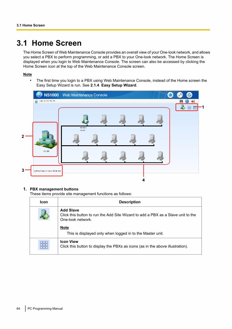
3.1 Home ScreenThe Home Screen of Web Maintenance Console provides an overall view of your One-look network, and allowsyou select a PBX to perform programming, or add a PBX to your One-look network. The Home Screen isdisplayed when you login to Web Maintenance Console. The screen can also be accessed by clicking theHome Screen icon at the top of the Web Maintenance Console screen.
Note• The first time you login to a PBX using Web Maintenance Console, instead of the Home screen the
Easy Setup Wizard is run. See 2.1.4 Easy Setup Wizard.
3
1
4
2
1. PBX management buttonsThese items provide site management functions as follows:
Icon Description
Add SlaveClick this button to run the Add Site Wizard to add a PBX as a Slave unit to theOne-look network.
NoteThis is displayed only when logged in to the Master unit.
Icon ViewClick this button to display the PBXs as icons (as in the above illustration).
64 PC Programming Manual
3.1 Home Screen

Icon Description
List ViewClick this button to view the following information in a list format:• Site status indicator• Site ID (1–16)• Site Name• Location (MIB)
Specified at MIB info—SysLocation in 27.3.3 Network Service—[3-3]Client Feature—SNMP Agent.
• Status (INS or OUS)• PBX Mode• IP Address• MAC Address• PBX Version (software version)• PBX Region• Data Version• SRAM VersionYou can also perform PBX site management from this screen:• Click Registration to register Slave units that have been added using the Add
Site Wizard. For details, see 3.1.1 Home Screen—Add Site Wizard. You canalso click De-Registration or Forced De-Registration to remove Slave unitsfrom the One-look network.– When logged in to a Slave unit, only information for that Slave unit and the
Master unit is displayed.– You can register or de-register Slave units only in On-line mode.
• In the Backup Master drop-down list, select a site to designate it as the BackupMaster site, and then click OK. For details, see 1.2.3.1 One-look NetworkingSurvivability.
NoteIf you have already designated a Backup Master site and want to select adifferent site, first select Unassigned and click OK. Then, select the newBackup Master site.
2. Master unit PBX iconThis is the icon and unit name representing the Master unit PBX. Click this icon to open the Setup Screenfor this PBX. You can also right-click the icon and select to open either the Setup Screen or the MaintenanceScreen.Right-click the icon and select Normal Mode in the following cases:• The Master unit is offline and not operating, and you want to restore the Master unit to normal operation.• There has been a connection error with one or more Slave units, and you want to restore their
connection to the Master unit in the One-look network.3. PBX information
• The time of when Web Maintenance Console last received information from the PBX is displayed.• The uptime of the PBX is displayed (the total time since the PBX was last reset).
4. Slave unit PBX iconsThese 15 icons represent Slave unit PBXs under the control of the Master unit PBX. Units that have beenregistered display a unit name and are coloured in. Remaining available unit positions are shown as greyedout. You can right-click a registered PBX and select Maintenance, Setup, or Direct Login for that PBX.Selecting Direct Login will display the Login screen for that PBX. For details about the login procedure,see 2.1.3 Logging in to Web Maintenance Console.
PC Programming Manual 65
3.1 Home Screen
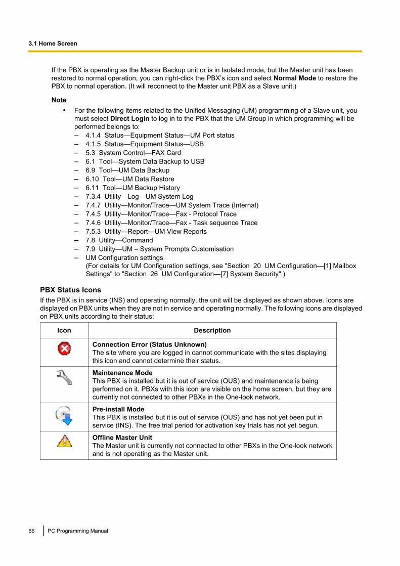
If the PBX is operating as the Master Backup unit or is in Isolated mode, but the Master unit has beenrestored to normal operation, you can right-click the PBX’s icon and select Normal Mode to restore thePBX to normal operation. (It will reconnect to the Master unit PBX as a Slave unit.)
Note• For the following items related to the Unified Messaging (UM) programming of a Slave unit, you
must select Direct Login to log in to the PBX that the UM Group in which programming will beperformed belongs to:– 4.1.4 Status—Equipment Status—UM Port status– 4.1.5 Status—Equipment Status—USB– 5.3 System Control—FAX Card– 6.1 Tool—System Data Backup to USB– 6.9 Tool—UM Data Backup– 6.10 Tool—UM Data Restore– 6.11 Tool—UM Backup History– 7.3.4 Utility—Log—UM System Log– 7.4.7 Utility—Monitor/Trace—UM System Trace (Internal)– 7.4.5 Utility—Monitor/Trace—Fax - Protocol Trace– 7.4.6 Utility—Monitor/Trace—Fax - Task sequence Trace– 7.5.3 Utility—Report—UM View Reports– 7.8 Utility—Command– 7.9 Utility—UM – System Prompts Customisation– UM Configuration settings
(For details for UM Configuration settings, see "Section 20 UM Configuration—[1] MailboxSettings" to "Section 26 UM Configuration—[7] System Security".)
PBX Status IconsIf the PBX is in service (INS) and operating normally, the unit will be displayed as shown above. Icons aredisplayed on PBX units when they are not in service and operating normally. The following icons are displayedon PBX units according to their status:
Icon Description
Connection Error (Status Unknown)The site where you are logged in cannot communicate with the sites displayingthis icon and cannot determine their status.
Maintenance ModeThis PBX is installed but it is out of service (OUS) and maintenance is beingperformed on it. PBXs with this icon are visible on the home screen, but they arecurrently not connected to other PBXs in the One-look network.
Pre-install ModeThis PBX is installed but it is out of service (OUS) and has not yet been put inservice (INS). The free trial period for activation key trials has not yet begun.
Offline Master UnitThe Master unit is currently not connected to other PBXs in the One-look networkand is not operating as the Master unit.
66 PC Programming Manual
3.1 Home Screen
3.1.1 Home Screen—Add Site WizardThe Add Site Wizard, which is run from the Home Screen, will add KX-NS1000 PBXs to your One-look networkas Slave units.
Note• The PBX to be added must have been configured as a Slave unit using the Easy Setup Wizard. See
2.1.4 Easy Setup Wizard.• To designate a Backup Master PBX, first add the PBX as a Slave unit to the One-look network using
the Add Site Wizard, and then select it as the Backup Master unit from the List View.1. To start the Add Site Wizard, click the Add Slave button ( ) on the Home screen. For details about the
Home Screen, see 3.1 Home Screen.2. Follow the prompts of the Add Site Wizard to complete the following settings:
– PBX Setting– Registration Setting– SNTP / Daylight Saving– Maintenance Setting
Note• The parameters which appear in the settings above are described in 2.1.4 Easy Setup Wizard.• If 2 or more sites will be added to the One-look network, repeat steps 1 and 2 for each site.
3. After the Add Site Wizard is completed, click Registration on the List View of the Home screen.4. A list of KX-NS1000 PBXs set up as Slave units will be displayed under Available Site. Select PBXs by
their assigned site names and click the right arrow to move them to Selected Site for Registration.Click Next to start the registration process.
5. On the Registration Executing screen, the status of PBXs being registered is displayed.6. On the Registration Completed screen, the result of the registration process is shown. Click Close to
continue.Registered Slave PBXs can now be viewed and selected on the Home Screen for programming.
Removing registered Slave units from the One-look networkTo remove a Slave unit from the One-look network, there are two methods: De-registration and ForcedDe-registration.
Method Description
De-registration • Registration information and settings for the Slave unit aredeleted from the Master unit.
• The De-registered Slave unit is reset to its initialised state(factory default state).
Forced De-Registration • Registration information and settings for the Slave unit aredeleted from the Master unit.
• The De-registered Slave unit is not reset to its initialisedstate. Information and settings registered on the Slave unitremain.
1. Set the Slave unit to be removed to out of service (OUS) status.2. From the List View of the Home Screen (see 3.1 Home Screen) click De-registration or Forced
De-registration.3. Select the PBX(s) by site name, click the arrow to move them to the selection box, and click Next.
A confirmation screen will be displayed.4. Click OK to continue.
PC Programming Manual 67
3.1.1 Home Screen—Add Site Wizard

A removal status screen will be displayed. Each selected PBX will be removed one at a time. After eachsuccessful removal, a confirmation message will appear. Click Continue to proceed to the next PBX toremove.
5. When all removal is complete, a message will be displayed. Click Close to finish.
68 PC Programming Manual
3.1.1 Home Screen—Add Site Wizard
Section 4
Status
This section serves as reference operating instructionsfor the Status menu of the Maintenance screen of WebMaintenance Console.
PC Programming Manual 69

4.1 Status—Equipment Status
4.1.1 Status—Equipment Status—UPSInformation is provided about the status of the UPS device and the connection to the PBX• UPS Connection Status
Displays if the UPS system is connected or not connected. If a UPS system is connected, the informationbelow will be displayed for the UPS system.
• Battery Voltage (V)The voltage of the UPS battery is displayed (0-240 V).
• Battery Charge Percentage (%)The remaining charge of the UPS battery is displayed (percentage value).
• Power SupplyDisplays the usage status of the UPS (if the UPS is engaged in supplying power to the PBX).
• UPS Shutdown Conditions - Battery levelFrom the drop-down list, select the amount of remaining battery level for when to initiate PBX shutdownprocedures.
For more information about setting up a UPS system, refer to 4.13 Starting the KX-NS1000—Connectingan Uninterruptible Power Supply (UPS) in the Installation Manual.
70 PC Programming Manual
4.1.1 Status—Equipment Status—UPS

4.1.2 Status—Equipment Status—CS InformationDisplays information stored by the PBX regarding each Cell Station (CS).This option is only available for the Installer level account in On-line mode and requires that the targetV-IPCS4 card be set to INS status.
The displayed items are as follows:
Item Description
Site Number of the site
Shelf Number of the shelf
Slot Number of the slot
Port Number of the port
CS Name Name of the attached CS
Status Service status of the attached CS: INS, OUS, or FAULT.If the status is FAULT, subsequent data items for that port will be leftblank.
Version Version number of the programme file stored in the CS
Revision Revision number of the programme file stored in the CS
CSID 12-digit ID number of the CS
Path Number of the wireless extension currently using each path. In the caseof a group, several extensions may be using the same floating extensionnumber.When an extension number is not registered, the display shows"OFF". The number of paths that can be used varies for each CS model.For more details, see the documentation for your CS.
Group Call Number of PSs registered to the attached CS that are members of a PSRing Group.
To view CS information1. From the Target CS I/F Shelf-Slot No. drop-down list, select the target shelf and slot.
• To display information on a single card, select the shelf number, slot number and name of that card.• To display information on all matching cards, select "All".
2. From the Interval Timer drop-down list, select the number of seconds between each automatic screenrefresh.
3. If you want to save the CS information, click Capture.a. Create a file for saving the data.b. Click Start.c. Click Close.
4. Click Start to begin monitoring.Monitoring will be performed and the screen will refresh according to the interval specified.
5. Click Stop to end monitoring.6. If you started to save the CS information in step 3, click Capture, then click Stop to record the information
to the specified file.7. Click Close to return to the main screen.
PC Programming Manual 71
4.1.2 Status—Equipment Status—CS Information

4.1.3 Status—Equipment Status—PS InformationDisplays Portable Station (PS) registration information, including the associated Cell Station (CS).This option is only available for the Installer level account in On-line mode.
The displayed items are as follows:
Item Description
PS No. PS location number.Only registered PSs will be displayed.
Extension Number Extension number of the PS.
Location Slot Slot number of the CS that the PS is registered with.
Location Port Port number of the CS that the PS is registered with.
72 PC Programming Manual
4.1.3 Status—Equipment Status—PS Information
4.1.4 Status—Equipment Status—UM Port statusThe UM Port status screen displays each port’s status and number for the Unified Messaging system. Thescreen will be updated every 30 seconds. Each port’s status will be displayed in one of the following ways:• Online (Ready): The port is ready to be used.• Incoming Call: The port is handling an incoming call.• Outgoing Call: An outgoing service is being processed.• Error Occurred: An error has been detected.• Off Line: The port is offline.This screen can be accessed only in On-line mode.
PC Programming Manual 73
4.1.4 Status—Equipment Status—UM Port status

4.1.5 Status—Equipment Status—USBUSB Mount Status indicates if a USB memory device is connected to the PBX. There is also an Unmountbutton.• Mounted: A USB memory device is connected to the PBX. Before removing the USB memory device from
the PBX, click Unmount.
NoteIf a mounted memory device is removed from the PBX without first clicking Unmount, the data on theUSB memory device may be damaged.
• None: No USB memory device is detected by the PBX.This screen can be accessed only in On-line mode.
74 PC Programming Manual
4.1.5 Status—Equipment Status—USB

Section 5
System Control
This section serves as reference operating instructionsfor the System Control menu of the Maintenance screenwhen programming using Web Maintenance Console.
PC Programming Manual 75
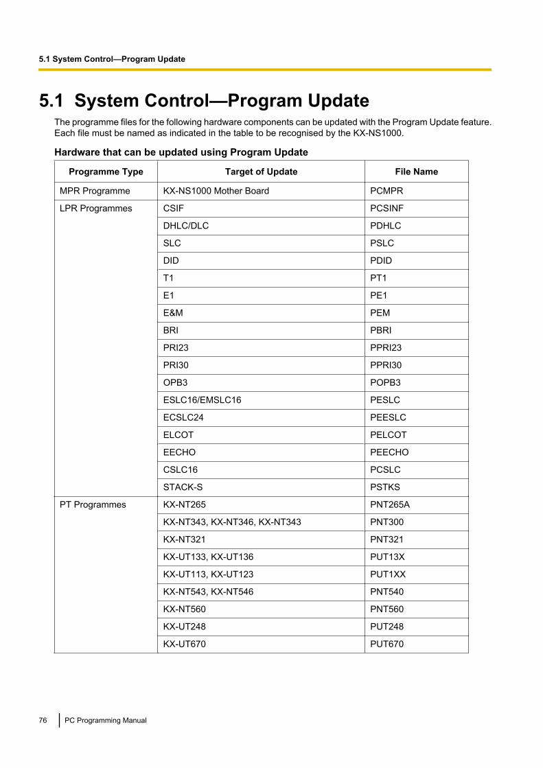
5.1 System Control—Program UpdateThe programme files for the following hardware components can be updated with the Program Update feature.Each file must be named as indicated in the table to be recognised by the KX-NS1000.
Hardware that can be updated using Program Update
Programme Type Target of Update File Name
MPR Programme KX-NS1000 Mother Board PCMPR
LPR Programmes CSIF PCSINF
DHLC/DLC PDHLC
SLC PSLC
DID PDID
T1 PT1
E1 PE1
E&M PEM
BRI PBRI
PRI23 PPRI23
PRI30 PPRI30
OPB3 POPB3
ESLC16/EMSLC16 PESLC
ECSLC24 PEESLC
ELCOT PELCOT
EECHO PEECHO
CSLC16 PCSLC
STACK-S PSTKS
PT Programmes KX-NT265 PNT265A
KX-NT343, KX-NT346, KX-NT343 PNT300
KX-NT321 PNT321
KX-UT133, KX-UT136 PUT13X
KX-UT113, KX-UT123 PUT1XX
KX-NT543, KX-NT546 PNT540
KX-NT560 PNT560
KX-UT248 PUT248
KX-UT670 PUT670
76 PC Programming Manual
5.1 System Control—Program Update

Programme Type Target of Update File Name
Firmware forKX-NS1000
PFPGA PFPGA
PAPMIRNR PAPMIRNR
PARMVDNR PARMVDNR
PARMIREP PARMIREP
PARMVDEP PARMVDEP
PC300NR PC300NR
PC300EP PC300EP
PC300DAG PC300DAG
Unified Messaging(UM) Programme
PFAX PFAX
CS Programmes CS using a CSIF card for DECT Portable Station PCSDECT
CS using a CSIF card for 2.4 GHz PortableStation
PCS24G
CS using a DHLC/DLC card for DECT PortableStation
PDCSDECT
CS using a DHLC/DLC card for 2.4 GHz PortableStation
PDCS24G
High-density CS for DECT Portable Station PHCSDECT
IP-CS for DECT Portable Station PICSDCT
PC Programming Manual 77
5.1 System Control—Program Update

5.1.1 System Control—Program Update—Download Program FileSoftware updates for PBX hardware components can be downloaded to the PBXs in the One-look network.Manual and automatic methods are available.Programme downloading can be performed only in On-line mode.
Note• If these operations are performed when logged in to a Slave unit, only the manual method can be used,
and files may only be acquired from a local PC or a USB memory device.• When using an FTP server with this feature, the programme files to be downloaded to the
KX-NS1000 PBX must be named on the FTP server in a specific way that includes the version number.Example: "PNT300_xxx_xxx_xxx"("xxx_xxx_xxx" is the version number.)
ManualUsing manual operations, the location of updated PBX software is specified and downloaded to the Masterunit, and then transferred to any Slave units.To download programme files manually1. In Location of program files, specify the location of the updated files from the Look in drop-down list.
The choices are as follows:• Local PC
Click Browse and specify the location of the updated programme files stored on the PC logged in toWeb Maintenance Console.
• USB MemoryIf a USB memory device is inserted into the PBX, the contents of the following directory on the devicewill be checked for updated files:/private/meigroup/psn/ippbx/update
• FTP ServerThe PBX connects to the specified FTP server and checks for updated files. Specify an FTP serverfrom the FTP connection name drop-down list, and specify the number of attempts to connect to theFTP server in No. of retries.To specify a new FTP site, see 27.3.1 Network Service—[3-1] Client Feature—FTP.
• Master UnitThe most recent versions of files previously downloaded to the Master unit are displayed.
2. Specify which PBX programme files will be automatically downloaded by checking the boxes next to eachhardware item.
3. For FTP Server onlyClick Check to confirm the connection to the FTP server. If a connection is established, the Execute buttonwill become active.
4. Click Execute, and then click OK on the confirmation message that appears. When the transfer is complete,click OK.
Note• If downloading cannot be completed within 10 minutes (due to slow network speeds or other connection
problems), the download operation will be cancelled.• The Master unit’s FTP server function must be enabled for Slave units to download programme files.
See 27.2.2 Network Service—[2-2] Server Feature—FTP.
AutomaticThe Master unit is set to automatically check an FTP server for updated programme files. If an update isavailable, the Master unit will download the data. The downloaded software is then sent over the One-looknetwork from the Master unit to all Slave units.
78 PC Programming Manual
5.1.1 System Control—Program Update—Download Program File

To download programme files automatically1. For Download Server, select an FTP site.
To specify a new FTP site, see 27.3.1 Network Service—[3-1] Client Feature—FTP.2. For Download mode, select one of the following:
• None: No actions are taken (automatic downloading is disabled).• Check only: The specified download server is checked at the specified times. If an e-mail is entered
in Email notification, an e-mail notification is sent when updated files have been discovered.
NoteIf Check only is selected, updated files will have to be downloaded manually (see the manualprocedure above).
• Download automatically: The specified download server is checked at the specified times. If updatedfiles are discovered, they will be downloaded automatically to the PBX. If an e-mail is entered in Emailnotification, an e-mail notification is sent when updated files have been downloaded.
3. In Check time and date, specify when the PBX will contact the server to check for updates. The checkcan be performed on a daily or weekly basis.
4. In Email notification specify up to 2 e-mail addresses that will receive an e-mail notification when updatedfiles have been discovered or when updated files have been downloaded.
NoteIf Download automatically is not selected in step 2, specify at least one e-mail address so that anadministrator will be notified when updated files have been discovered.
5. To begin automatic checking for updates according to Check time and date, click Execute.6. The PBX will now periodically perform checks and downloads as specified in the settings. Click Download
Cancel on this screen to stop automatic programme updates.
NoteWhen the system is downloading data from an FTP server, if downloading cannot be completed within 10minutes (due to slow network speeds or other connection problems), the download operation will becancelled.
PC Programming Manual 79
5.1.1 System Control—Program Update—Download Program File

5.1.2 System Control—Program Update—Update Program FileOnce updated programme files have been downloaded and are stored on a PBX, they can be used to updatethe system files of the PBX. The update process can be set to be automatically performed at a specified time,or the update process can be carried out manually.You must be connected to the PBX in On-line mode to update programme files.
NoteBefore updating programme files, we strongly recommend making a backup of all system files. For details,refer to the following:– 6.1 Tool—System Data Backup to USB– 6.9 Tool—UM Data Backup
For Program Update Type, select Immediately or Timed Update.
Immediately (Manual update)Specify which cards or devices to update, and perform the update immediately.1. In Email Notification, specify up to 2 e-mail addresses that will receive a notification when programme
files have been updated.2. Updated programme files that can be used to update cards or devices installed in the system are listed in
Available Program File(s). In Select the target to update, specify which cards or devices will be updatedusing the files listed by checking the boxes next to each item.
NoteWhen selecting an item, a warning message may be displayed. Confirm the contents of the warning,and then click OK to continue.
3. Click Apply.4. Click on another PBX site tab to programme another PBX in the One-look network as required, and then
repeat steps 1–3. Perform settings for each PBX in the One-look network as required.5. Click Execute.
The programme files are updated to the specified PBXs.
Note• Updated PBXs reset when the update is complete.• If this operation is performed when logged in to a Slave unit only the PBX mother board and hardware
specifically registered to the Slave unit may be updated.
Timed Update (Automatic update)Specify which cards or devices to update and a time to execute the update.1. In Email Notification, specify up to 2 e-mail addresses that will receive a notification when programme
files have been updated.2. Updated programme files that can be used to update cards or devices installed in the system are listed in
Available Program File(s). In Select the target to update, specify which cards or devices will be updatedusing the files listed by checking the boxes next to each item.
NoteWhen selecting an item, a warning message may be displayed. Confirm the contents of the warning,and then click OK to continue.
3. In Update Time, specify the time of day when the update will be executed.4. Click Apply.5. Click on another PBX site tab to programme another PBX in the One-look network as required, and then
repeat steps 1–4. Perform settings for each PBX in the One-look network as required.
80 PC Programming Manual
5.1.2 System Control—Program Update—Update Program File
6. Click Execute.The programme files will be updated to the specified PBXs at the specified time.
Note• All PBXs in a One-look network must be using the same version of the software. When updating PBXs
connected in a One-look network, note the following:– Apply the same version of the software update to all the PBXs in the One-look network.– When updating the programme files for multiple PBXs, an immediate (manual) update is
recommended. For Automatic (timed) updates, set the same Update Time for all PBXs in theOne-look network.
• At most, the process of updating all PBXs in the network can take approximately 30 minutes tocomplete.
• For CS programme files, in order for CS cards to be displayed on this screen, the cards must be setto INS, and the ports of the card must be set to OUS.
PC Programming Manual 81
5.1.2 System Control—Program Update—Update Program File

5.1.3 System Control—Program Update—Plug and UpdateThe Plug and Update feature allows IP-PTs to be automatically updated to the latest software version whenthey are registered to the PBX. When Plug and Update is enabled, the version number of the system softwarestored on the Master unit is compared to the system software currently in the IP-PT, after the IP-PT has beenregistered to the PBX. If the software on the Master unit is newer, it is downloaded to the IP-PT. Plug andUpdate can be enabled for each site in a One-look network using the following procedure:The Plug and Update screen lists the PBXs in the One-look network by site number and site name. By default,Plug and Update is set to Off for all sites.1. In Plug & Update, select On for each to enable this feature.2. Click OK.
82 PC Programming Manual
5.1.3 System Control—Program Update—Plug and Update

5.2 System Control—MOH
5.2.1 System Control—MOH—InstallSound files on the programmer’s PC can be installed to each PBX for use as Music on Hold (MOH).This screen can be accessed only in On-line mode.1. Click Browse and select a WAV file to install as an MOH file. Only one file may be installed at a time.2. In the Select column, specify which PBX sites will install the sound file as an MOH file.3. As uploading the file to the PBX may require some time, a time can be set in Time Set.4. In BGM No., specify which BGM number the MOH file will occupy.5. Click Execute to confirm the settings. If "Now" is set for Time Set, the installation will begin at this time.
Note• Users logged in to the Master unit can see the status of all One-look network sites. Users logged in to
a Slave unit may only view the status of that PBX.• Only WAV files can be installed, and file names must not exceed 57 characters in length (including the
file extension ".wav"). If non-alphabetic characters are used, the file name must not exceed 14characters in length.
• Some language codes for file names are not supported, and file names may not display correctly afterthey are installed on the PBX. To ensure proper display, use only the ASCII character set for file names.
• Files may not be larger than 80 MB in size.• User (User) level accounts cannot perform this procedure.
PC Programming Manual 83
5.2.1 System Control—MOH—Install
5.2.2 System Control—MOH—DeleteMOH files that are occupying BGM numbers can be deleted.This screen can be accessed only in On-line mode.1. In BGM No., specify the BGM numbers to delete MOH files from. Specify "All" to delete the data saved in
all BGM numbers.2. In the Select column, specify which PBX sites will delete MOH files from the specified BGM numbers.3. Click Execute to delete the files of the specified BGM numbers.
Note• Users logged in to the Master unit can see the status of all One-look network sites. Users logged in to
a Slave unit may only view the status of that PBX.• User (User) level accounts cannot perform this procedure.
84 PC Programming Manual
5.2.2 System Control—MOH—Delete
5.2.3 System Control—MOH—Status / BackupMOH files stored on a PBX can be downloaded to the user’s PC.This screen can be accessed only in On-line mode.1. From Site No., select a PBX from which to download MOH files.2. The MOH files saved to the PBX will be listed. Click Backup for the file you would like to back up. One file
can be backed up at a time.3. A save file dialogue will appear. Specify the directory on the PC to back up the file to.4. Click OK when finished.
Note• Users logged in to the Master unit can see the status of all One-look network sites. Users logged in to
a Slave unit may only view the status of that PBX.• Remained Capacity Time indicates the amount of time available for new MOH files to be added. The
amount of time of any MOH files scheduled to be uploaded in 5.2.1 SystemControl—MOH—Install is not reflected in this value.
• User (User) level accounts cannot perform this procedure.
PC Programming Manual 85
5.2.3 System Control—MOH—Status / Backup
5.3 System Control—FAX CardThis function is used to restart the optional FAX Card after it is installed in the PBX. For details about installingthe FAX Card, refer to 4.3.4 FAX Card (KX-NS0106) in the Installation Manual.This screen can be accessed only in On-line mode.1. Click Execute.2. Click OK.3. The card is restarted and a confirmation message is displayed. Click OK.
86 PC Programming Manual
5.3 System Control—FAX Card

5.4 System Control—System ResetWhen programming changes or other changes to PBX settings require a system reset, this command allowsa reset to be performed remotely from Web Maintenance Console.When the system is reset, any settings not saved to the Storage Memory Card are lost. A backup should beperformed before the reset to ensure no data is lost. However, a backup should not be performed if settingsor data have recently been imported into the system, because performing a backup would overwrite theimported data with the current PBX settings.This screen can be accessed only in On-line mode.1. Confirm the contents of the displayed warning message.2. Click Backup or Skip according to the system’s status:
• Backup: Click to backup system settings. The system will be reset after the backup has beenperformed.
• Skip: The system is reset without performing a backup.If you are logged in to the PBX that is reset using this command, it is necessary to re-log in to Web MaintenanceConsole to continue programming.
PC Programming Manual 87
5.4 System Control—System Reset
5.5 System Control—System ShutdownIn order to turn off the power to a PBX, it must first be issued a shutdown command using Web MaintenanceConsole. Follow the procedure below to prepare a PBX for system shutdown.When the system is shut down, any settings not saved to the Storage Memory Card are lost. A backup shouldbe performed before the shutdown to ensure no data is lost. However, a backup should not be performed ifsettings or data have recently been imported into the system, because performing a backup would overwritethe imported data with the current PBX settings.This screen can be accessed only in On-line mode.1. Select the PBX site(s) to shut down in the Select Site drop-down menu.2. Confirm the contents of the displayed warning message.3. Click Backup or Skip according to the system’s status:
• Backup: Click to backup system settings. The system will prepare for shutdown after the backup hasbeen performed.
• Skip: The system is prepared for shutdown without performing a backup.4. The STATUS LED on the front of the PBX will flash amber. When shutdown preparations are completed,
the STATUS LED will stop flashing and remain a solid amber. Once the STATUS LED stops flashing, youmay turn off the power switch on the back of the PBX.
88 PC Programming Manual
5.5 System Control—System Shutdown

Section 6
Tool
This section serves as reference for the Tool menu ofthe Maintenance screen of Web Maintenance Console.
PC Programming Manual 89

6.1 Tool—System Data Backup to USBA PBX’s system data can be backed up to a USB memory device inserted into the PBX’s USB port. At a latertime, the USB memory device can be used to restore the backed up system data to a PBX.This screen can be accessed only in On-line mode.
To back up the system data to a USB memory device1. Insert a USB memory device into the USB port of the PBX.
Note• To check the inserted USB memory’s status, see 4.1.5 Status—Equipment Status—USB.• The USB memory device must be compatible for use with the PBX. For details, refer to
4.10 Connection of Peripherals—USB Interface for Uninterruptible Power Supply (UPS) andUSB Memory Device—Using a USB memory device in the Installation Manual.
• If an uninterruptible power supply (UPS) device is connected to the PBX with a USB cable, theUSB cable must first be removed, then reconnected after the backup to USB has been completed.For details about the connection between the UPS and the PBX, refer to 4.13 Starting theKX-NS1000—Connecting an Uninterruptible Power Supply (UPS) in the Installation Manual.
2. Select the system data items to backup.• System Data
System data includes programming information for the PBX, including extension and networkconfiguration information.
• MOH + OGMMOH (Music on Hold) and OGM (Outgoing Message) sound files stored on the PBX are backed up.
• Activation KeyActivation key files that were installed on the PBX are backed up.
Any or all of the above items may be selected. However, the system cannot be restored unless SystemData is specified.
3. Click Execute to back up the specified files. If backup data already exists on the USB memory device, itwill be deleted. A confirmation message will be displayed. Click Continue.
4. A time estimation for the backup will be displayed. Click Continue.5. A progress bar is displayed to indicate the progress of the backup. A message will be displayed when the
backup is finished. Click OK.
Note• Unified Messaging (UM) data must be backed up using a separate process. See 6.9 Tool—UM Data
Backup.• Use a USB memory device with a capacity of at least 512 MB. During the backup process, if an error
message is displayed indicating there is not enough free memory space on the USB memory device,delete other unnecessary files on the USB memory device, or use a USB memory device with a largercapacity.
Restoring backed up data from a USB memory device to a PBXFollow the procedure below to restore the backed up data to a PBX.
NoteThe restoration process first requires an initialisation of the PBX, which returns the PBX to its factory defaultstate. Under the following conditions, restoration may not be possible, even though the PBX has beeninitialised.• The USB memory device hardware is faulty.• The data on the USB memory device has become corrupted.• The USB memory device is removed from the USB port of the PBX during the restoration process.
90 PC Programming Manual
6.1 Tool—System Data Backup to USB

To minimise the potential of a failed backup, connect the USB memory device to a PC to confirm the USBmemory device is operational and that the backup data is intact before starting this restore process.
1. The PBX must be in a powered-off state.2. Insert the USB memory device with the backup data into the USB port of the PBX.3. Set the PBX’s System Mode Switch to the "SYSTEM INITIALIZE" position.4. Turn on the PBX’s power switch. The STATUS indicator will flash green. Slide the System Mode Switch
back to the "NORMAL" position. The restore process will begin and the STATUS indicator will flash rapidly.5. When the restoration process is completed, the PBX will restart automatically.
PC Programming Manual 91
6.1 Tool—System Data Backup to USB

6.2 Tool—BRI Automatic ConfigurationAutomatically configures the network settings of the BRI card.This option is only available at Installer level in On-line mode.This tool automatically inputs values into the fields L1 Mode, L2 Mode, Access Mode, and TEIMode, on the Network tab of the 9.27 PBX Configuration—[1-1] Configuration—Slot—Port Property -BRI Port screen.
Note• To use this tool, the card to be configured must be pre-set to OUS status. For more details, see
2.1.6 Card Status.• At any time on this screen, you can click Cancel to return to the previous screen without saving.
To configure the BRI card1. In Check, select the card, and then click OK.2. Click Execute.
The results of the automatic configuration will be displayed.3. Click the Check Box cell for the ports that have been configured.4. Click Data Apply to save these results to the BRI card.
92 PC Programming Manual
6.2 Tool—BRI Automatic Configuration
6.3 Tool—NDSS Link Data ClearClears NDSS Link Data stored in the connected PBX. While this tool clears both monitor extension andmonitored extension data, it only clears it at the connected PBX. To clear this data at other PBXs in the QSIGnetwork, it is necessary to run this tool at those PBXs.This screen can be accessed only in On-line mode.
To clear the NDSS Link DataWhen this tree menu item is selected, a confirmation screen will be displayed.• Click OK to clear the data.• Click Cancel to keep the data, and close the screen.
PC Programming Manual 93
6.3 Tool—NDSS Link Data Clear

6.4 Tool—Call Pickup for My GroupAllows you to automatically configure settings in 10.6.2 PBX Configuration—[2-6-2] System—NumberingPlan—Quick Dial and 12.1.3 PBX Configuration—[4-1-3] Extension—Wired Extension—Speed Dial sothat users can answer calls to their Call Pickup Group by pressing " 0".
To activate this tool1. When this tree menu item is selected, a confirmation screen will be displayed.2. Click Yes.
The Group Call Pickup feature number (default: 40) + the extension user group number of the extensionis assigned to first personal speed dial.
NoteThis tool can only be activated if all of the following conditions are met:– The first Quick Dial setting is empty or is already set to " 0".– " 0" is not used for another feature number.– The Group Call Pickup feature number has been assigned.– The Personal Speed Dialling feature number has been assigned.
94 PC Programming Manual
6.4 Tool—Call Pickup for My Group
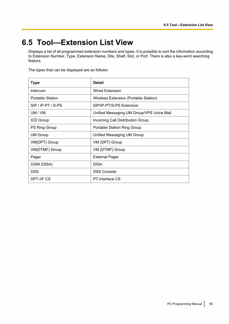
6.5 Tool—Extension List ViewDisplays a list of all programmed extension numbers and types. It is possible to sort the information accordingto Extension Number, Type, Extension Name, Site, Shelf, Slot, or Port. There is also a key-word searchingfeature.
The types that can be displayed are as follows:
Type Detail
Intercom Wired Extension
Portable Station Wireless Extension (Portable Station)
SIP / IP-PT / S-PS SIP/IP-PT/S-PS Extension
UM / VM Unified Messaging UM Group/VPS Voice Mail
ICD Group Incoming Call Distribution Group
PS Ring Group Portable Station Ring Group
UM Group Unified Messaging UM Group
VM(DPT) Group VM (DPT) Group
VM(DTMF) Group VM (DTMF) Group
Pager External Pager
OGM (DISA) DISA
DSS DSS Console
DPT-I/F CS PT-interface CS
PC Programming Manual 95
6.5 Tool—Extension List View
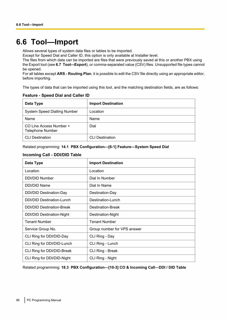
6.6 Tool—ImportAllows several types of system data files or tables to be imported.Except for Speed Dial and Caller ID, this option is only available at Installer level.The files from which data can be imported are files that were previously saved at this or another PBX usingthe Export tool (see 6.7 Tool—Export), or comma-separated value (CSV) files. Unsupported file types cannotbe opened.For all tables except ARS - Routing Plan, it is possible to edit the CSV file directly using an appropriate editor,before importing.
The types of data that can be imported using this tool, and the matching destination fields, are as follows:
Feature - Speed Dial and Caller ID
Data Type Import Destination
System Speed Dialling Number Location
Name Name
CO Line Access Number +Telephone Number
Dial
CLI Destination CLI Destination
Related programming: 14.1 PBX Configuration—[6-1] Feature—System Speed Dial
Incoming Call - DDI/DID Table
Data Type Import Destination
Location Location
DDI/DID Number Dial In Number
DDI/DID Name Dial In Name
DDI/DID Destination-Day Destination-Day
DDI/DID Destination-Lunch Destination-Lunch
DDI/DID Destination-Break Destination-Break
DDI/DID Destination-Night Destination-Night
Tenant Number Tenant Number
Service Group No. Group number for VPS answer
CLI Ring for DDI/DID-Day CLI Ring - Day
CLI Ring for DDI/DID-Lunch CLI Ring - Lunch
CLI Ring for DDI/DID-Break CLI Ring - Break
CLI Ring for DDI/DID-Night CLI Ring - Night
Related programming: 18.3 PBX Configuration—[10-3] CO & Incoming Call—DDI / DID Table
96 PC Programming Manual
6.6 Tool—Import

ARS - Leading Digit
Data Type Import Destination
Location Location
Leading Number Leading Digit
Additional Number of Digits Additional Dial Digits
Routing Plan Number Route Plan Number
Related programming: 16.2 PBX Configuration—[8-2] ARS—Leading Number
ARS - Except Code
Data Type Import Destination
Location Location
Leading Number Exception Exception Code
Related programming: 16.6 PBX Configuration—[8-6] ARS—Leading Number Exception
ARS - Routing Plan
Data Type Import Destination
(no fields to select) (no fields to select)
Related programming: 16.3 PBX Configuration—[8-3] ARS—Routing Plan Time
Wired Extension
Data Type Import Destination
No. Location (selected automatically)
Extension Number Extension Number (selected automatically)
Extension Name Extension Name (selected automatically)
Related programming: 12.1.1 PBX Configuration—[4-1-1] Extension—Wired Extension—ExtensionSettings
PS Extension
Data Type Import Destination
No. Location (selected automatically)
Extension Number*1 Extension Number (selected automatically)
Extension Name Extension Name (selected automatically)
*1 This data can only be exported, and cannot be imported.
Related programming: 12.2.1 PBX Configuration—[4-2-1] Extension—Portable Station—ExtensionSettings
PC Programming Manual 97
6.6 Tool—Import

Quick Dial*
Data Type Import Destination
No. Location
Dial Dial
Phone Number Phone Number
Related programming: 10.6.2 PBX Configuration—[2-6-2] System—Numbering Plan—Quick Dial*: Refer to Notices Regarding Importing Data from KX-TDE/KX-NCP PBXs to the KX-NS1000 below.
SIP Extension
Data Type Import Destination
No. Location
Extension Number Extension Number
Password* Password
Related programming: 9.17 PBX Configuration—[1-1] Configuration—Slot—V-SIPEXT32—Port Property*: Refer to Notices Regarding Importing Data from KX-TDE/KX-NCP PBXs to the KX-NS1000 below.
V-IPGW16 GW Settings
Data Type Import Destination
No. Location
GW Name GW Name
GW IP Address GW IP Address
GW Group GW Group No.
Connection for IP-GW16 Connection for IP-GW16
Protocol Protocol
Progress Tone Send Mode Progress Tone Send Mode
IP Codec Priority 1st IP Codec Priority 1st
IP Codec Priority 2nd IP Codec Priority 2nd
IP Codec Priority 3rd IP Codec Priority 3rd
Packet Sampling Time (G.711A) Packet Sampling Time (G.711A)
Packet Sampling Time (G.711Mu) Packet Sampling Time (G.711Mu)
Packet Sampling Time (G.729A) Packet Sampling Time (G.729A)
Voice Activity Detection for G.711 Voice Activity Detection for G.711
FAX Sending Method FAX Sending Method
Maximum Bit Rate Maximum Bit Rate
FAX Detection Ability FAX Detection Ability
DTMF DTMF
98 PC Programming Manual
6.6 Tool—Import

Data Type Import Destination
Payload Type Payload Type
T38 FAX Max Datagram T38 FAX Max Datagram
T38 FAX UDPTL Error Correction –Redundancy
T38 FAX UDPTL Error Correction – Redundancy
T38 FAX UDPTL Redundancy countfor T.30 messages
T38 FAX UDPTL Redundancy count for T.30 messages
T38 FAX UDPTL Redundancy countfor data
T38 FAX UDPTL Redundancy count for data
T38 FAX Rate Management Method T38 FAX Rate Management Method
Related programming: 9.4 PBX Configuration—[1-1] Configuration—Slot—System Property—GWSettings–Main
V-IPGW16 DN2IP
Data Type Import Destination
No. Location
Leading Number Leading Number
Remaining Number of Digits Remaining Number of Digits
GW No./GW Group Selection GW No./GW Group Selection
GW Group GW Group
GW No. GW No.
Related programming: 9.4 PBX Configuration—[1-1] Configuration—Slot—System Property—DN2IP
V-SIPGW16 Settings
Data Type Import Destination
(no fields to select) (no fields to select)
Related programming: 9.11 PBX Configuration—[1-1] Configuration—Slot—V-SIPGW—Port Property
V-SIPGW16 Provider
Data Type Import Destination
(no fields to select) (no fields to select)
Related programming: 9.11 PBX Configuration—[1-1] Configuration—Slot—V-SIPGW—Port Property
PS Registration
Data Type Import Destination
(no fields to select) (no fields to select)
Related programming: 9.31 PBX Configuration—[1-2] Configuration—Portable Station
PC Programming Manual 99
6.6 Tool—Import
NoteBefore importing PS registration settings, be sure to de-register any PSs already registered to theKX-NS1000 PBX.
To import system data1. From the Tool tree menu, select Import, and then click the type of data to import.2. Navigate to the folder containing the system data file you want to open.3. Select the file.4. Click OK to open the file.
If applicable, a list of field names found in the imported file will be displayed.5. For the Feature - Speed Dial and Caller ID table, select the Speed Dial table to which to import the data
(system or tenant) from the drop-down list.6. If required, select import fields.
When import fields can be selected, the selection screen is displayed automatically. Matching origin anddestination fields are entered by default.• To change the destination for an import field, select the preferred field from the drop-down list.• To not import a field, select the blank option from the drop-down list.
7. Click OK to perform the import operation.Depending on the type of data imported, the relevant programming screen may be displayed.• Click OK or Apply to complete the import operation.If data in a field being imported does not match the required format for the import destination, an errormessage will be displayed when the import operation is attempted, and the operation will be cancelled.This can occur when, for example, the destination field can only accept numeric data, but the data beingimported contains alphabet characters, as the correct fields were not linked together.
Notices Regarding Importing Data from KX-TDE/KX-NCP PBXs to the KX-NS1000Quick DialThe KX-NS1000 only supports an 8-digit Quick Dial format. Therefore, KX-TDE/KX-NCP Quick Dial data inthe 4-digit format cannot be imported to the KX-NS1000.
SIP Extension – PasswordKX-TDE/KX-NCP PBXs allow 3-digit passwords, but KX-NS1000 PBXs require password with 4 digits or more.When importing password data from KX-TDE/KX-NCP PBXs to the KX-NS1000, any 3-digit passwords willnot be imported and the password entry will be left blank.
100 PC Programming Manual
6.6 Tool—Import
6.7 Tool—ExportAllows several types of system data to be exported to files. These files can be used with the Import tool (see6.6 Tool—Import) to update another PBX.Except for ARS - Routing Plan, tables are exported as comma-separated value (CSV) files.Except for Speed Dial and Caller ID, this option is only available at Installer level.
NoteThe separator used in CSV files created using the Export tool is decided by the unit specified in ListSeparator, found in the Windows Control Panel’s "Regional Options".
To export system data1. From the Tool tree menu, select Export, and then click the type of data to export.2. Select the check boxes next to the names of the fields to export, and then click OK.3. If a message window is displayed, click OK.4. In the file selection screen, select the Save check box, and then click OK.
PC Programming Manual 101
6.7 Tool—Export

6.8 Tool—Screen CustomiseAllows you to specify which Setup and Maintenance screens can be accessed in the User (Administrator)account level.This option is only available at Installer level.Selected check boxes will be displayed in the tree menus of Web Maintenance Console to users with the User(Administrator) account level.
To modify displayed screens1. Click the access level to modify.2. Select the items that you want to have displayed.
• Clear the check box beside the names of items you do not want to have displayed.• Select the check box beside the names of items you want to have displayed.
3. Click OK.
102 PC Programming Manual
6.8 Tool—Screen Customise
6.9 Tool—UM Data BackupThe UM Data Backup tool can be used to backup and restore Unified Messaging (UM) data.This screen can be accessed only in On-line mode.The following voice data can be backed up or restored as individual files. The data can be backed up to a USBmemory device connected to the PBX.a. System Prompts
– Installed Prompts– Custom Service Menu– Company Name– Company Greetings– System Mailbox Group Voice Label– System Caller Name– Prompt Selection– Hold Announce Menu
b. Mailbox Prompts– Owner Name– Personal Greetings– Personal Caller ID Name– Interview– Personal Group List Name– EMD List Member Name
c. Mailbox Messages
NoteMailbox data may not be backed up if the mailbox is in use during the backup process. Additionally, UnifiedMessaging system response time may be affected when backing up data. For these reasons, werecommend backing up data when the Unified Messaging system is not in use.
The UM Data Backup tool can be executed manually or scheduled to run automatically at regular intervals.Refer to the following:• 6.9.1 Tool—UM Data Backup—Manual Backup• 6.9.2 Tool—UM Data Backup—Scheduled Backup
PC Programming Manual 103
6.9 Tool—UM Data Backup
6.9.1 Tool—UM Data Backup—Manual BackupUse this procedure to manually back up Unified Messaging system data. For details on the items that can bebacked up, see 6.9 Tool—UM Data Backup.1. To back up system prompts, select the check box next to System Prompts and select the check boxes
of the items you want to back up.2. To back up mailbox prompts, select the check box next to Mailbox Prompts and select which prompts to
back up.3. To back up the prompts for specific mailboxes, click Mailbox Prompts to open the mailbox list. Check the
top checkbox to select all mailboxes, or select the mailboxes for which you wish to back up prompts, thenclick OK.
4. To back up mailbox messages, check the box next to Mailbox Messages button and click MailboxMessages to open the mailbox list. Select the top check box to select all mailboxes, or select the mailboxesyou wish to back up, and then click OK.
5. Select the destination for the backed up data:• Local PC: After the backup is started, a file download will begin in your web browser. Specify a location
on your local PC to save the backup data.• USB Flash Drive (Main Unit): Back up the data to a USB memory device connected to the Master
Unit PBX. When USB Flash Drive (Main Unit) is selected, a folder selection menu becomes active.Specify a folder on the USB memory device for saving the backup data.
NoteBefore selecting this option, make sure that a USB memory device is connected to the Master UnitPBX.
6. Click OK to start the backup.
Note• The system will prepare the data to be backed up, and the backup will begin about 30 seconds later.
The time needed to backup the data will vary depending on the communication speed and the amountof data that is being backed up.
• Deleted messages will not be backed up when backing up Mailbox Messages.• To back up the Unified Messaging data of a Slave unit in a One-look network, log in to the Slave unit
and perform the backup operation from the Slave unit.• When Local PC is selected, individual messages that are larger than 100 MB cannot be backed up.• Depending on your browser or your browser’s settings, a prompt may appear during the backup for
each file to be downloaded. Be sure to select an action for each prompt that appears.
104 PC Programming Manual
6.9.1 Tool—UM Data Backup—Manual Backup
6.9.2 Tool—UM Data Backup—Scheduled BackupYou can schedule backups in advance. The Unified Messaging system will automatically back up the selecteddata at the scheduled times to a USB memory device connected to the PBX. (Scheduled backups cannot bemade to a local PC.) For details on the items that can be backed up, see 6.9 Tool—UM Data Backup.Follow the procedure below to schedule an automatic backup.1. Click to create a new scheduled backup.2. Enter a description for the backup.3. Set the frequency (daily, weekly, etc.) and time of day when the backup should take place.4. Check the desired item(s) to backup.5. Click Edit next to Mailbox Prompts.6. Check either All Mailboxes or select the mailboxes you wish to backup.7. Click OK.8. Click Edit next to Mailbox Messages.9. Check either All Mailboxes or select the mailboxes you wish to backup. You can also specify the following
backup conditions:• Retention Days: Back up only messages that have been stored on the system for at least the number
of days specified.• Remaining mailbox Capacity (min): Only perform a backup if the remaining mailbox capacity has
reached the specified amount.• Delete After Backup: Specify to delete messages that have been backed up from the mailbox.• Message Type: Specify to back up all messages, or only messages marked as "old".
NoteAn invalid combination of these settings may prevent a backup from occurring. For example, if a mailboxis full, but there are no messages older than the number of days specified in Retention Days, or nomessages are marked as "old", the backup will not be performed.
10. In System backup folder (USB), specify the folder on the USB memory device where you want to savethe system backup file.
11. Click OK.12. In Status, select Enable and click OK.
Note• Up to 20 backup events can be scheduled.• If a backup is scheduled, but a USB memory device is not connected to the PBX at the time of the
scheduled backup, the backup will not be performed.
Editing a scheduled backup1. From the Scheduled Backup screen, select the backup you wish to edit.2. Click Edit.3. Edit the settings as desired.4. Click OK.
Deleting a scheduled backup1. From the Scheduled Backup screen, select the backup you wish to delete.2. Click Delete.3. Click Yes.4. Click OK.
PC Programming Manual 105
6.9.2 Tool—UM Data Backup—Scheduled Backup
6.10 Tool—UM Data RestoreFollow the procedure below to restore data backed up using the UM Data Backup tool.This screen can be accessed only in On-line mode.For more information about the UM Data Backup tool, see 6.9 Tool—UM Data Backup. You can restore datafrom a USB memory device connected to the PBX or from a file on your local PC.1. Select the check boxes of the items to restore.2. In System Restore, select Local PC or USB Flash Drive (Main Unit).
• Local PCClick Browse and select a backup file from your local PC. The file must have been saved using theUM Data Backup tool.
• USB Flash Drive (Main Unit)When USB Flash Drive (Main Unit) is selected, the folder selection menu becomes active. Specifythe folder on the USB memory device where the backup data is saved.
NoteBefore selecting USB Flash Drive (Main Unit), make sure that the USB memory device with thebackup data is connected to the Master unit PBX.
To restore a single file:Files that match the selected types of items to restore will be highlighted.Click a file in the list to display its name in the text box. You can also click a folder name to display thatfolder’s contents, and then click a file to select it.
To restore multiple files at once:Folders whose contents match the selected types of items to restore will be highlighted.Click a folder in the list to display its name in the text box. You can also click a folder name to display thatfolder’s contents, and then click a folder to select it.
NoteWhen restoring data from a local PC, multiple files cannot be selected at one time.
3. Click OK to restore the selected file or folder of files.• Local PC
The results of the data restore will be downloaded from the PBX as a text file called"UM_data_restore_result.txt". Save the file to your local PC to view its contents.
• USB Flash Drive (Main Unit)The results of the data restore will be saved in a text file called "UM_data_restore_result.txt" on theUSB memory device. To view this file, you must connect the USB memory device to a PC and thenopen the text file.
Note• When restoring multiple items, only files that match the items for which check boxes have been selected
will be restored. Also, even if data exists in the specified folder of the USB memory device, the datawill not be restored unless the check box of the matching item has been selected.
• Data in sub-folders of a selected folder will not be restored.• If more than one file matches a selected item, the newest file will be restored.• The backup file names stored on the USB memory device should not be changed. If the file names are
changed, the system may not be able to detect which backup files correspond to which UM data items.• A backed up message cannot be restored to the subscriber’s mailbox if the mailbox still contains a
New/Old/Deleted copy of the same message.• Voice data recorded by users in a KX-TVA/KX-TVM series VPS can be converted and used as voice
data in the KX-NS1000’s Unified Messaging system. For details, refer to 5.3 Starting Web
106 PC Programming Manual
6.10 Tool—UM Data Restore

Maintenance Console—KX-TVA/KX-TVM System Prompt and Mailbox Data Import in theInstallation Manual.
PC Programming Manual 107
6.10 Tool—UM Data Restore

6.11 Tool—UM Backup HistoryThe following records for backup that have been performed can be checked on this screen:• Description• Parameters• Completion Status• Date & Time• Total Elapsed Time (HH:MM:SS)This screen can be accessed only in On-line mode.
108 PC Programming Manual
6.11 Tool—UM Backup History

6.12 Tool—DXDP All OUSSets the status of all DXDP/XDP extension ports to "OUS" simultaneously for the currently selected site.
To set all DXDP/XDP ports to OUS for the currently selected site1. Access Tool—DXDP All OUS from the Maintenance Screen tree view.2. Click OK.
PC Programming Manual 109
6.12 Tool—DXDP All OUS

6.13 Tool—Contact informationDealers can set contact information for the user of the PBX here. When users select this tree menu item, thisinformation will be displayed for the user’s reference.1. Input the following information, and then click OK.
• Company Name• Telephone Number• Fax Number• Address• URL• Email Address
110 PC Programming Manual
6.13 Tool—Contact information
6.14 Tool—UT Option SettingOption settings can be specified for KX-UT series SIP phones on a system-wide level.
NoteThe following apply when programming in On-line mode only:• To apply changes made to these settings for KX-UT series SIP phones connected to Slave unit PBXs
in a One-look network, be sure to click the icon after programming. Otherwise, there may be a delayof 30 minutes or more before changed settings are applied.
• To set these parameters, all installed V-UTEXT32 cards must first be set to OUS. For details, see9.1 PBX Configuration—[1-1] Configuration—Slot.
Numbering Plan for UT Series TerminalOne or more number dialling plans can be specified for KX-UT series SIP phones. Enter the dial plan text stringinto the text box, and then click OK. A dial plan text string may also be copied and pasted into the text boxfrom another source.
Note• For more information about dial plans, refer to the Administrator Guide of the relevant KX-UT series
SIP phone.• You can enter up to 500 characters in the dial plan text box.• You can assign up to 20 dial plans, separating them with a "|" (vertical bar).• You can assign up to 32 digits per dial plan.• When OK is clicked, the entered text string will be validated. If there is a validation error, a message
will be displayed.
Timer for UT Series TerminalThis timer specifies for KX-UT series SIP phones how long the system waits for another digit to be dialledbefore determining that dialling has finished. This value will apply for all KX-UT series SIP phones connectedto the PBX. Specify a number of seconds in Extension Inter-digit (s), and then click OK.
PC Programming Manual 111
6.14 Tool—UT Option Setting
6.15 Tool—URL InformationThe URL addresses for downloading the IMAP tool and the Fax Driver can be specified on this screen. TheseURL addresses will be used for the Unified Messaging Plug in and Fax Driver Tool download buttonsdisplayed to users when they view the Unified Message tab of their profile in the User menu. For details, see8.2.1 Users—Add User—Single User.
Specify valid URL addresses for Unified Messaging Plug in and/or Fax Driver Tool, and then click OK.
112 PC Programming Manual
6.15 Tool—URL Information

Section 7
Utility
This section serves as reference operating instructionsfor the Utility menu of the Maintenance screen of WebMaintenance Console.
PC Programming Manual 113

7.1 Utility—Diagnosis
7.1.1 Utility—Diagnosis—Card DiagnosisPerforms diagnostic tests on cards installed in the PBX, to identify the source of problems.If any of the tests listed here returns the result "NG" ("No Good"), contact your dealer.When testing is complete, any cards that were set to OUS status must be returned to INS status if they are tobe used again.This screen can be accessed only in On-line mode.
Card TestTests the relevant functions of a card to ensure that it is operating correctly. The tests carried out vary accordingto the type of card being tested.
The tests that are performed on each card are listed below.
NoteTests marked with a "*" are available only for cards installed on a legacy gateway. For details, see 9.29 PBXConfiguration—[1-1] Configuration—Slot—Legacy-GW1/Legacy-GW2. For more information aboutcards installed in legacy gateways, refer to the documentation of the legacy gateway PBX.
Test Type Available Cards
Local loop back diagnosis KX-NS1000 PBXs:SLC2, LCOT2, BRI4, PRILegacy Gateways:DHLC, DLC, SLC8, SLC16, MSLC16, ESLC16, EMSLC16,CSLC16, MCSLC16, ECSLC24, MCSLC24, CSIF, LCOT8,LCOT16, ELCOT, T1, E1, BRI2, BRI4, BRI8, PRI, OPB, E&M, DID
Card CT Bus diagnosis* DHLC, DLC, SLC8, SLC16, MSLC16, EMSLC16, CSLC16,ECSLC24, CSIF, LCOT, ELCOT, T1, E1, BRI, PRI, OPB, E&M, DID
DTMF Receive test port KX-NS1000 PBXs:SLC2Legacy Gateways:DHLC, SLC8, SLC16, MSLC16, MCSLC16, ESLC16, EMSLC16,CSLC16, ECSLC24, MCSLC24, E&M, DID
PT loop back diagnosis* DHLC, DLC
DSP DTMF generator/receiverdiagnosis*
T1, E1
DSP DTMF receiver diagnosis* T1, E1
Framer IC alarm signal detectiondiagnosis*
T1, E1, PRI
Framer IC error detection diagnosis KX-NS1000 PBXs:PRILegacy Gateways:T1, E1, PRI
114 PC Programming Manual
7.1.1 Utility—Diagnosis—Card Diagnosis
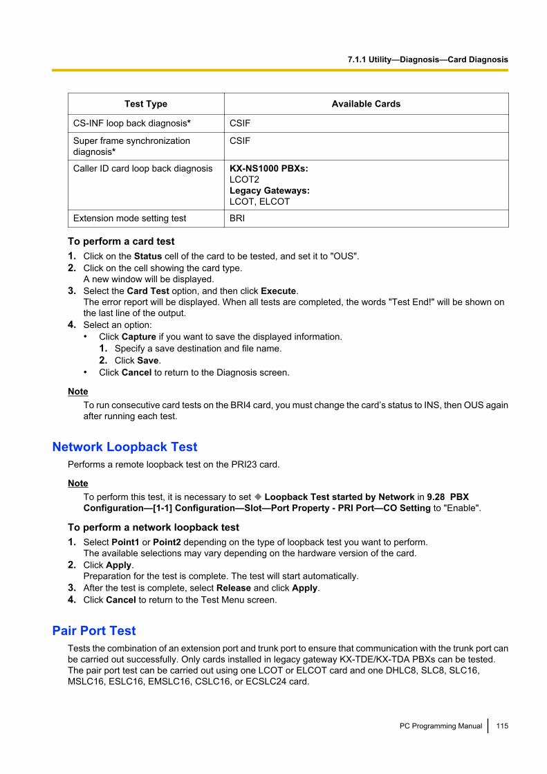
Test Type Available Cards
CS-INF loop back diagnosis* CSIF
Super frame synchronizationdiagnosis*
CSIF
Caller ID card loop back diagnosis KX-NS1000 PBXs:LCOT2Legacy Gateways:LCOT, ELCOT
Extension mode setting test BRI
To perform a card test1. Click on the Status cell of the card to be tested, and set it to "OUS".2. Click on the cell showing the card type.
A new window will be displayed.3. Select the Card Test option, and then click Execute.
The error report will be displayed. When all tests are completed, the words "Test End!" will be shown onthe last line of the output.
4. Select an option:• Click Capture if you want to save the displayed information.
1. Specify a save destination and file name.2. Click Save.
• Click Cancel to return to the Diagnosis screen.
NoteTo run consecutive card tests on the BRI4 card, you must change the card’s status to INS, then OUS againafter running each test.
Network Loopback TestPerforms a remote loopback test on the PRI23 card.
NoteTo perform this test, it is necessary to set Loopback Test started by Network in 9.28 PBXConfiguration—[1-1] Configuration—Slot—Port Property - PRI Port—CO Setting to "Enable".
To perform a network loopback test1. Select Point1 or Point2 depending on the type of loopback test you want to perform.
The available selections may vary depending on the hardware version of the card.2. Click Apply.
Preparation for the test is complete. The test will start automatically.3. After the test is complete, select Release and click Apply.4. Click Cancel to return to the Test Menu screen.
Pair Port TestTests the combination of an extension port and trunk port to ensure that communication with the trunk port canbe carried out successfully. Only cards installed in legacy gateway KX-TDE/KX-TDA PBXs can be tested.The pair port test can be carried out using one LCOT or ELCOT card and one DHLC8, SLC8, SLC16,MSLC16, ESLC16, EMSLC16, CSLC16, or ECSLC24 card.
PC Programming Manual 115
7.1.1 Utility—Diagnosis—Card Diagnosis
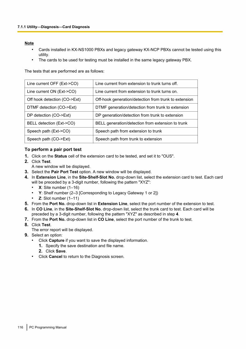
Note• Cards installed in KX-NS1000 PBXs and legacy gateway KX-NCP PBXs cannot be tested using this
utility.• The cards to be used for testing must be installed in the same legacy gateway PBX.
The tests that are performed are as follows:
Line current OFF (Ext->CO) Line current from extension to trunk turns off.
Line current ON (Ext->CO) Line current from extension to trunk turns on.
Off hook detection (CO->Ext) Off-hook generation/detection from trunk to extension
DTMF detection (CO->Ext) DTMF generation/detection from trunk to extension
DP detection (CO->Ext) DP generation/detection from trunk to extension
BELL detection (Ext->CO) BELL generation/detection from extension to trunk
Speech path (Ext->CO) Speech path from extension to trunk
Speech path (CO->Ext) Speech path from trunk to extension
To perform a pair port test1. Click on the Status cell of the extension card to be tested, and set it to "OUS".2. Click Test.
A new window will be displayed.3. Select the Pair Port Test option. A new window will be displayed.4. In Extension Line, in the Site-Shelf-Slot No. drop-down list, select the extension card to test. Each card
will be preceded by a 3-digit number, following the pattern "XYZ":• X: Site number (1–16)• Y: Shelf number (2–3 [Corresponding to Legacy Gateway 1 or 2])• Z: Slot number (1–11)
5. From the Port No. drop-down list in Extension Line, select the port number of the extension to test.6. In CO Line, in the Site-Shelf-Slot No. drop-down list, select the trunk card to test. Each card will be
preceded by a 3-digit number, following the pattern "XYZ" as described in step 4.7. From the Port No. drop-down list in CO Line, select the port number of the trunk to test.8. Click Test.
The error report will be displayed.9. Select an option:
• Click Capture if you want to save the displayed information.1. Specify the save destination and file name.2. Click Save.
• Click Cancel to return to the Diagnosis screen.
116 PC Programming Manual
7.1.1 Utility—Diagnosis—Card Diagnosis

7.1.2 Utility—Diagnosis—PingPerforms a connection test on network devices. This function sends echo requests to a particular IP addressacross an IP network, and displays the result of responses and round-trip time.This screen can be accessed only in On-line mode.
To perform a Ping test1. Enter a specific IP address in the IP Address box.2. Click Test to perform the test.
The result will be displayed.3. Select an option:
• Click Capture if you want to save the displayed information.1. Enter a file name, or select a file to overwrite.2. Click Save.
• Click Cancel to return to the Ping screen.
PC Programming Manual 117
7.1.2 Utility—Diagnosis—Ping
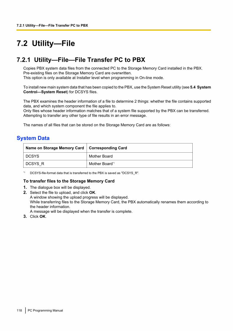
7.2 Utility—File
7.2.1 Utility—File—File Transfer PC to PBXCopies PBX system data files from the connected PC to the Storage Memory Card installed in the PBX.Pre-existing files on the Storage Memory Card are overwritten.This option is only available at Installer level when programming in On-line mode.
To install new main system data that has been copied to the PBX, use the System Reset utility (see 5.4 SystemControl—System Reset) for DCSYS files.
The PBX examines the header information of a file to determine 2 things: whether the file contains supporteddata, and which system component the file applies to.Only files whose header information matches that of a system file supported by the PBX can be transferred.Attempting to transfer any other type of file results in an error message.
The names of all files that can be stored on the Storage Memory Card are as follows:
System DataName on Storage Memory Card Corresponding Card
DCSYS Mother Board
DCSYS_R Mother Board*1
*1 DCSYS-file-format data that is transferred to the PBX is saved as "DCSYS_R".
To transfer files to the Storage Memory Card1. The dialogue box will be displayed.2. Select the file to upload, and click OK.
A window showing the upload progress will be displayed.While transferring files to the Storage Memory Card, the PBX automatically renames them according tothe header information.A message will be displayed when the transfer is complete.
3. Click OK.
118 PC Programming Manual
7.2.1 Utility—File—File Transfer PC to PBX
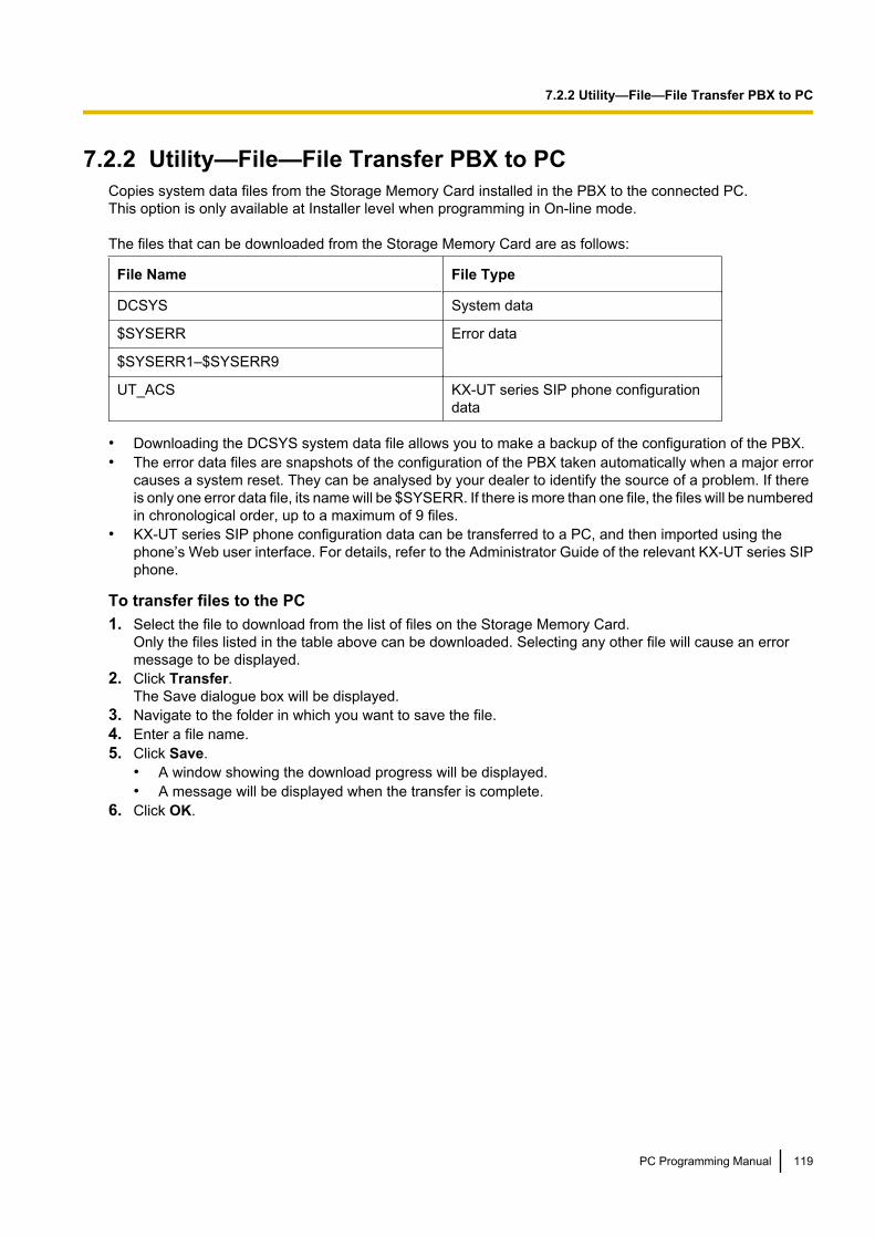
7.2.2 Utility—File—File Transfer PBX to PCCopies system data files from the Storage Memory Card installed in the PBX to the connected PC.This option is only available at Installer level when programming in On-line mode.
The files that can be downloaded from the Storage Memory Card are as follows:
File Name File Type
DCSYS System data
$SYSERR Error data
$SYSERR1–$SYSERR9
UT_ACS KX-UT series SIP phone configurationdata
• Downloading the DCSYS system data file allows you to make a backup of the configuration of the PBX.• The error data files are snapshots of the configuration of the PBX taken automatically when a major error
causes a system reset. They can be analysed by your dealer to identify the source of a problem. If thereis only one error data file, its name will be $SYSERR. If there is more than one file, the files will be numberedin chronological order, up to a maximum of 9 files.
• KX-UT series SIP phone configuration data can be transferred to a PC, and then imported using thephone’s Web user interface. For details, refer to the Administrator Guide of the relevant KX-UT series SIPphone.
To transfer files to the PC1. Select the file to download from the list of files on the Storage Memory Card.
Only the files listed in the table above can be downloaded. Selecting any other file will cause an errormessage to be displayed.
2. Click Transfer.The Save dialogue box will be displayed.
3. Navigate to the folder in which you want to save the file.4. Enter a file name.5. Click Save.
• A window showing the download progress will be displayed.• A message will be displayed when the transfer is complete.
6. Click OK.
PC Programming Manual 119
7.2.2 Utility—File—File Transfer PBX to PC

7.2.3 Utility—File—File ViewDisplays a list of files on the Storage Memory Card.This screen can be accessed only in On-line mode.The name, date and time of creation, and size of files are displayed.This utility can also display information on activation key files stored in the Storage Memory Card.The effective date, PCMPR-ID, activation key type, number of activation keys, and expiration date of activationkeys are displayed on the Detail screen.
To view information of programme and activation key files stored in the Storage Memory Card1. Click on the name of the desired programme or activation key file.2. Click Detail. The Detail screen will be displayed. You can select different files from the File drop-down
menu to view the details for each file.
120 PC Programming Manual
7.2.3 Utility—File—File View

7.2.4 Utility—File—File DeleteAllows you to delete files from the Storage Memory Card.This option is only available at Installer level in On-line mode.The DCSYS system file cannot be deleted by this utility.
NoteProgramme files cannot be deleted if the Program Update feature’s timed update is set, or if an update iscurrently being performed. For details, see 5.1.2 System Control—Program Update—Update ProgramFile.
To delete files from the Storage Memory Card1. Click on the file to be deleted.2. Click Delete.
A confirmation screen will be displayed.3. Click OK.
The display will return to the File Delete screen.
PC Programming Manual 121
7.2.4 Utility—File—File Delete

7.2.5 Utility—File—Message File Transfer PC to PBXTransfers Outgoing Message (OGM) files from the PC to the Storage Memory Card.This option is only available at Installer level when programming in On-line mode.Uploaded files are automatically renamed as necessary. If the location specified already contains an OGM, itwill be overwritten by the newly uploaded message.
To transfer OGMs to the Storage Memory Card1. From the Utility menu, select Message File Transfer PC to PBX.2. Select the destination to transfer the OGM files to from the drop-down list, and then click Browse.
The Open dialogue box will be displayed.3. Select the message files to upload. The files must be in the WAV format.
It is possible to select multiple files.
Note• When selecting files to copy to the PBX, the file names (apart from the file extension) cannot be
more than 33 characters in length.• When selecting G.711 codec WAV files to copy to the PBX, the total file size of all selected files
combined cannot exceed 32 megabytes.4. Click OK.
• The files will be uploaded. Files that do not contain message data will be ignored.• An index number (01 to 64) will be appended automatically to the file names of message files
transferred to the PBX.• When complete, the display will return to the main screen.
122 PC Programming Manual
7.2.5 Utility—File—Message File Transfer PC to PBX
7.2.6 Utility—File—Message File Transfer PBX to PCTransfers Outgoing Message (OGM) files from the Storage Memory Card to the PC.This option is only available at Installer level when programming in On-line mode.
To transfer OGMs to the PC1. From the lower drop-down list, select the messages to transfer.
• To transfer a certain message, select the number of that message.• To transfer all messages at once, select "ALL".The Save dialogue box will be displayed.
2. Enter a file name.3. Click Save.4. Click OK.
• When you choose to transfer all messages, each message is saved as an individual file, with a numberappended to the file name corresponding to that message’s location on the Storage Memory Card.
• When complete, the display will return to the main screen.
PC Programming Manual 123
7.2.6 Utility—File—Message File Transfer PBX to PC
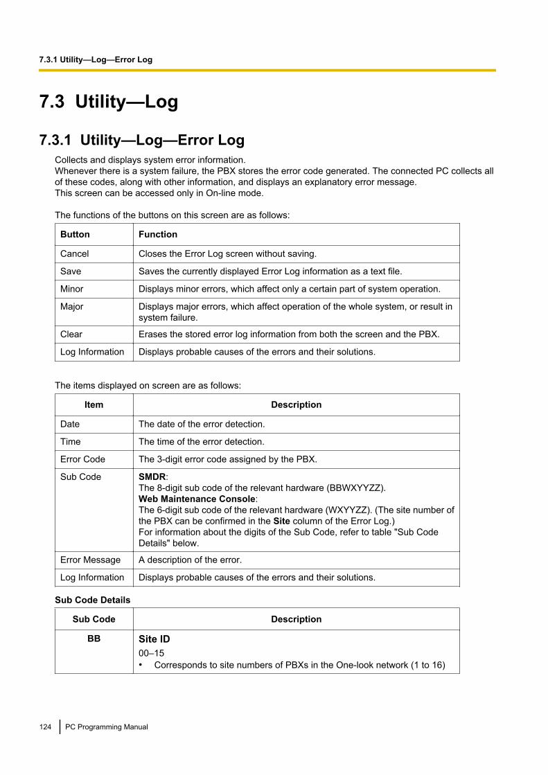
7.3 Utility—Log
7.3.1 Utility—Log—Error LogCollects and displays system error information.Whenever there is a system failure, the PBX stores the error code generated. The connected PC collects allof these codes, along with other information, and displays an explanatory error message.This screen can be accessed only in On-line mode.
The functions of the buttons on this screen are as follows:
Button Function
Cancel Closes the Error Log screen without saving.
Save Saves the currently displayed Error Log information as a text file.
Minor Displays minor errors, which affect only a certain part of system operation.
Major Displays major errors, which affect operation of the whole system, or result insystem failure.
Clear Erases the stored error log information from both the screen and the PBX.
Log Information Displays probable causes of the errors and their solutions.
The items displayed on screen are as follows:
Item Description
Date The date of the error detection.
Time The time of the error detection.
Error Code The 3-digit error code assigned by the PBX.
Sub Code SMDR:The 8-digit sub code of the relevant hardware (BBWXYYZZ).Web Maintenance Console:The 6-digit sub code of the relevant hardware (WXYYZZ). (The site number ofthe PBX can be confirmed in the Site column of the Error Log.)For information about the digits of the Sub Code, refer to table "Sub CodeDetails" below.
Error Message A description of the error.
Log Information Displays probable causes of the errors and their solutions.
Sub Code Details
Sub Code Description
BB Site ID00–15• Corresponds to site numbers of PBXs in the One-look network (1 to 16)
124 PC Programming Manual
7.3.1 Utility—Log—Error Log

Sub Code Description
W Slot TypeFor physical slots (including physical slots of legacy gateway PBXs)
– " " (blank)For KX-NS1000 virtual slots
– "*" (asterisk)
X Shelf Number• – KX-NS1000 unit: 1
– Legacy gateway: 2–3– Convert process: 4– Non-PBX process: 5
YY Slot NumberWhen X is not 4 or 5
Physical shelfMother board slot: 00Regular slots: 01–05
Legacy gatewaySTACK-S card: 00Optional physical service card slots:– KX-TDE600/KX-TDA600: 01–10– KX-TDE620/KX-TDA620: 01–11– KX-NCP500/KX-NCP1000/KX-NS1020: 01–07
(Slots 04 and 07 are disregarded for KX-NCP500 PBXs)Virtual shelf
Virtual Trunk slots: 31–46Virtual Extension slots: 47–66Virtual IP-CS slots: 67–82
When X is 4YY: Convert code
When X is 5YY: Process code
ZZ Port NumberWhen X is not 4 or 5
ZZ: Optional service card port number (01–XX)
When X is 4ZZ: Convert code
When X is 5ZZ: Process number (determined by each process)
NoteWhen there is no parameter for slot and port number, YY and ZZ will be displayed as "00".Example: Sub code for the mother board = "01 10000"
PC Programming Manual 125
7.3.1 Utility—Log—Error Log

7.3.2 Utility—Log—SyslogDisplays a log of system events. Each entry in the log includes the following information:• Type: Describes the type of system event.• Date: The date and time the system event occurred.• Message: Details about the system event.This screen can be accessed only in On-line mode.
126 PC Programming Manual
7.3.2 Utility—Log—Syslog

7.3.3 Utility—Log—Web-MC Event LogThe Web-MC Event Log retains information about user interaction with Web Maintenance Console.This screen can be accessed only in On-line mode.The items displayed on screen are as follows:
Item Description
Date The date of the event.
Time The time of the event.
User The account name of the user accessing Web Maintenance Console.
Description A description of the action taken by the user. (i.e. "Login toWeb-MC")
IP Address The IP address of the PC used to access Web Maintenance Console.
To save the event log as a text file1. From the Web-MC Event Log screen, select Save.
The Save dialogue box will be displayed.2. Enter a file name.3. Click Save.
To clear the event log1. From the Web-MC Event Log screen, select Clear.
NoteUsers logged in to a Master unit can see all events. Users logged in to a Slave unit can only view the eventsfor that unit.
PC Programming Manual 127
7.3.3 Utility—Log—Web-MC Event Log

7.3.4 Utility—Log—UM System LogYou can export a log of events from the Unified Messaging system for troubleshooting purposes.This screen can be accessed only in On-line mode.1. Click OK to export a UM System Log file.2. Click Save to save the data to a local file.3. Click OK.
128 PC Programming Manual
7.3.4 Utility—Log—UM System Log
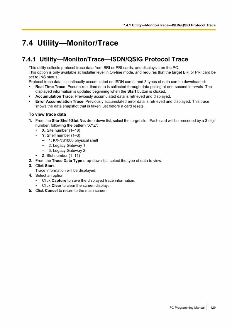
7.4 Utility—Monitor/Trace
7.4.1 Utility—Monitor/Trace—ISDN/QSIG Protocol TraceThis utility collects protocol trace data from BRI or PRI cards, and displays it on the PC.This option is only available at Installer level in On-line mode, and requires that the target BRI or PRI card beset to INS status.Protocol trace data is continually accumulated on ISDN cards, and 3 types of data can be downloaded:• Real Time Trace: Pseudo-real-time data is collected through data polling at one-second intervals. The
displayed information is updated beginning when the Start button is clicked.• Accumulation Trace: Previously accumulated data is retrieved and displayed.• Error Accumulation Trace: Previously accumulated error data is retrieved and displayed. This trace
shows the data snapshot that is taken just before a card resets.
To view trace data1. From the Site-Shelf-Slot No. drop-down list, select the target slot. Each card will be preceded by a 3-digit
number, following the pattern "XYZ":• X: Site number (1–16)• Y: Shelf number (1–3)
– 1: KX-NS1000 physical shelf– 2: Legacy Gateway 1– 3: Legacy Gateway 2
• Z: Slot number (1–11)2. From the Trace Data Type drop-down list, select the type of data to view.3. Click Start.
Trace information will be displayed.4. Select an option:
• Click Capture to save the displayed trace information.• Click Clear to clear the screen display.
5. Click Cancel to return to the main screen.
PC Programming Manual 129
7.4.1 Utility—Monitor/Trace—ISDN/QSIG Protocol Trace

7.4.2 Utility—Monitor/Trace—V-IPGW16 Protocol TraceThis utility collects trace data of protocol activity from V-IPGW16 card.This option is only available at Installer level in On-line mode, and requires that the target V-IPGW16 card beset to INS status.
To save trace data to the Storage Memory Card1. From the Utility menu, select V-IPGW16 Protocol Trace.
When the progress bar disappears, the protocol trace is complete. The trace data has been saved to theStorage Memory Card (file name: "PRTH323").
To transfer trace data to the PC1. Click the File Transfer PBX to PC link to access the file transfer screen.
The list of files will be displayed.
NoteThe file transfer screen can also be accessed from the tree menu (see 7.2.2 Utility—File—FileTransfer PBX to PC).
2. Select the desired trace data file.3. Click Transfer.4. Navigate to the folder in which you want to save the file.5. Enter a file name.6. Click Save.7. Click OK.
130 PC Programming Manual
7.4.2 Utility—Monitor/Trace—V-IPGW16 Protocol Trace
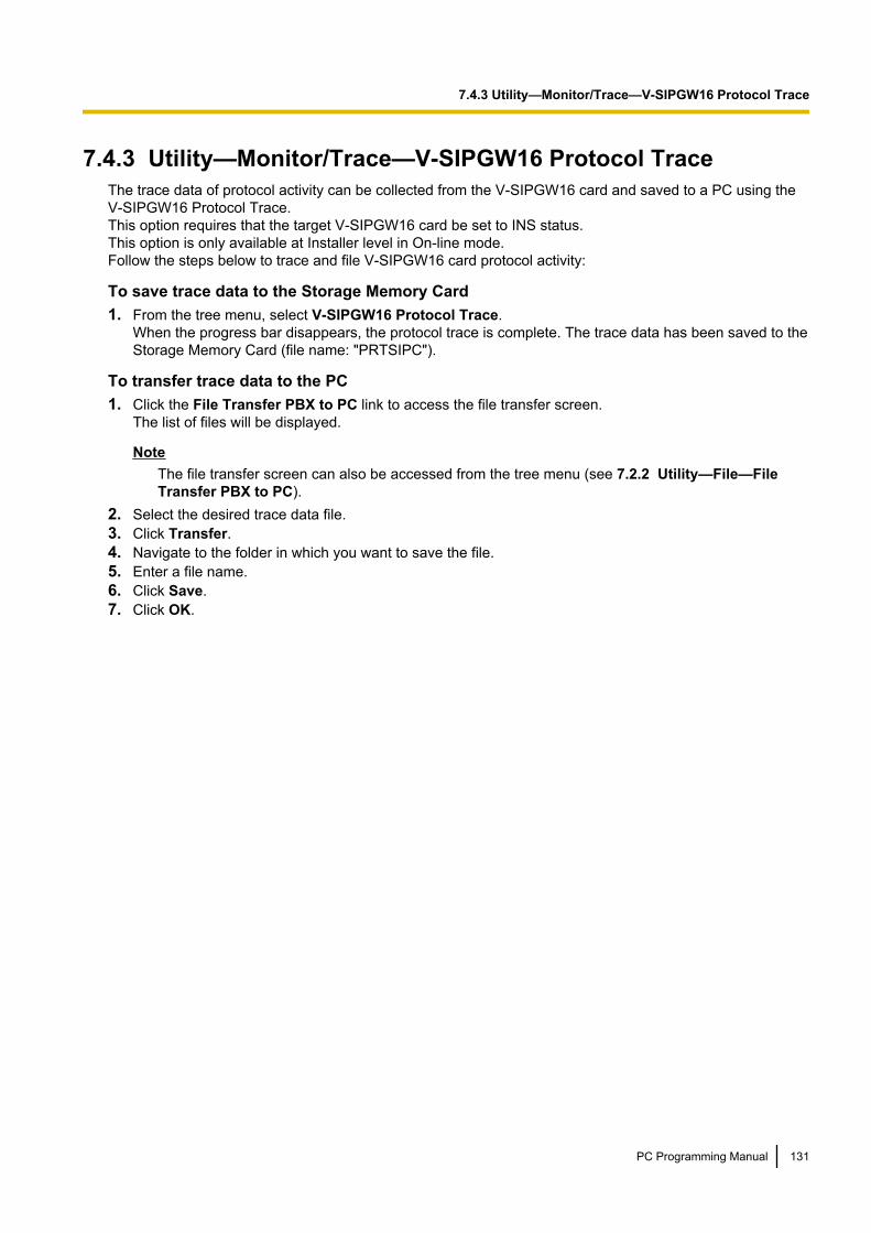
7.4.3 Utility—Monitor/Trace—V-SIPGW16 Protocol TraceThe trace data of protocol activity can be collected from the V-SIPGW16 card and saved to a PC using theV-SIPGW16 Protocol Trace.This option requires that the target V-SIPGW16 card be set to INS status.This option is only available at Installer level in On-line mode.Follow the steps below to trace and file V-SIPGW16 card protocol activity:
To save trace data to the Storage Memory Card1. From the tree menu, select V-SIPGW16 Protocol Trace.
When the progress bar disappears, the protocol trace is complete. The trace data has been saved to theStorage Memory Card (file name: "PRTSIPC").
To transfer trace data to the PC1. Click the File Transfer PBX to PC link to access the file transfer screen.
The list of files will be displayed.
NoteThe file transfer screen can also be accessed from the tree menu (see 7.2.2 Utility—File—FileTransfer PBX to PC).
2. Select the desired trace data file.3. Click Transfer.4. Navigate to the folder in which you want to save the file.5. Enter a file name.6. Click Save.7. Click OK.
PC Programming Manual 131
7.4.3 Utility—Monitor/Trace—V-SIPGW16 Protocol Trace

7.4.4 Utility—Monitor/Trace—CS Status MonitorThis utility monitors the status of CSs. CSs receive data from other CSs that they are currently synchronisedwith. Current Sync CS information is displayed for IP-CSs that are in INS status.This option is only available at Installer level in On-line mode.
The displayed items for the Current Sync CS of each CS are as follows:
Item Description
CS Type Type of CS that each CS is currently synchronised with.
Slot Type Slot type of the CS that each CS is currently synchronised with.
Slot Slot number of the CS that each CS is currently synchronised with.
Port Port number of the CS that each CS is currently synchronised with.
CS / Repeater Indicates whether the CS that each CS is currently synchronised with is aCS or Repeater.
CS Name Name of the CS that each CS is currently synchronised with.
CS ID 12-digit ID number of the CS that each CS is currently synchronised with.
Monitored Value Monitored value (dBm) of the CS that each CS is currently synchronisedwith.
Monitored Level Monitored level (signal strength level) of the CS that each CS is currentlysynchronised with.
To monitor the status of CSs1. From the Air Synchronisation Group Number drop-down list, select the desired Air Synchronisation
Group number.2. From the Interval Timer drop-down list, select the number of seconds between each automatic screen
refresh.3. Click Start to monitor the status of air synchronisation.
Monitoring will be performed and the screen will refresh according to the specified interval.4. Click Stop to end monitoring.5. To refresh the screen manually at any time, click Refresh.6. To collect the monitored data, click Start Capture.7. Click Stop Capture to finish and save the monitored data.
A dialogue box will be displayed.8. Navigate to the folder in which you want to save the file.9. Enter a file name.10. Click Save.
The dialogue box will close.
132 PC Programming Manual
7.4.4 Utility—Monitor/Trace—CS Status Monitor

7.4.5 Utility—Monitor/Trace—Fax - Protocol TraceThis screen displays trace information for faxes sent and received by the PBX’s FAX Card.This screen can be accessed only in On-line mode.The following information is recorded for each fax sent or received:• Date/Time• Status• Mode• Resolution• Speed• Remote Capacity• Local CapacityTo save a copy of the recorded information, click Save Trace and follow the prompts.
PC Programming Manual 133
7.4.5 Utility—Monitor/Trace—Fax - Protocol Trace

7.4.6 Utility—Monitor/Trace—Fax - Task sequence TraceThis screen displays a log of events related to fax activity.This screen can be accessed only in On-line mode.To save a copy of the log, click Save Trace and follow the prompts.
134 PC Programming Manual
7.4.6 Utility—Monitor/Trace—Fax - Task sequence Trace

7.4.7 Utility—Monitor/Trace—UM System Trace (Internal)Unified Messaging (UM) system processes can be monitored and logged.This screen can be accessed only in On-line mode.The following data can be traced and logged for each UM port, or all UM ports:• DTMF / Dial: data regarding DTMF signals received by the Unified Messaging system.• Guidance: guidance data that the Unified Messaging system played.• Message: Unified Messaging system activity for messages such as creating, playing and deleting.• Process Event: events occurred between Unified Messaging system processes such as Application, Call
Processor and DSP.• Caller ID: received Caller ID information.• DID: received DID numbers.• PIN: PINs received by the Unified Messaging system.Follow the steps below to monitor or log the system trace data.1. Select Internal Trace, Display, or Trace Clear.
– Setting1. Check Enable / Disable Trace Data.2. Check the data and UM ports you wish to monitor.3. Click OK.
– Display: Displays the trace data and/or error data.1. Check the data and UM ports you wish to monitor.2. To include error data, click the Error Trace tab and check Error Data.3. Click OK.4. The selected data will be displayed in a new window. Click the Trace Data or Error Trace tabs to
switch views. Click Save Log File to save a copy of the displayed data.5. Click Cancel when finished.
– Trace Clear: Clears saved trace data.1. Select the trace data to clear.2. Click OK to clear the selected trace data.3. The message "System Trace Clear Successful" will be displayed. Click OK to continue.
PC Programming Manual 135
7.4.7 Utility—Monitor/Trace—UM System Trace (Internal)

7.4.8 Utility—Monitor/Trace—T1/E1 Signalling Bit MonitorDisplays reference signalling bit information for all channels of a T1 or E1 card that is installed in a legacygateway by monitoring sent and received A, B, C and D bits. This utility is intended for use by dealers.For information about legacy gateways, see 9.29 PBX Configuration—[1-1]Configuration—Slot—Legacy-GW1/Legacy-GW2.This option is only available at the Installer level, and requires that the target card be set to INS status.While monitoring is being performed, any displayed bits whose value changes from 0 to 1 or vice versa will behighlighted in red until the next screen refresh is performed.
To view signalling bit information1. From the Site-Shelf-Slot No. drop-down list, select the target slot. Each card will be preceded by a 3-digit
number, following the pattern "XYZ":• X: Site number (1–16)• Y: Shelf number (2–3 [Corresponding to Legacy Gateway 1 or 2])• Z: Slot number (1–11)
2. From the Interval Timer drop-down list, select the number of seconds between each automatic screenrefresh.
3. Click Start.Monitoring will be performed and the screen will refresh according to the interval specified.
4. Click Stop to end monitoring.To refresh the screen at any time while monitoring is stopped, click Refresh.
136 PC Programming Manual
7.4.8 Utility—Monitor/Trace—T1/E1 Signalling Bit Monitor
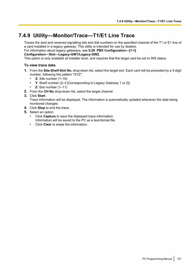
7.4.9 Utility—Monitor/Trace—T1/E1 Line TraceTraces the sent and received signalling bits and dial numbers on the specified channel of the T1 or E1 line ofa card installed in a legacy gateway. This utility is intended for use by dealers.For information about legacy gateways, see 9.29 PBX Configuration—[1-1]Configuration—Slot—Legacy-GW1/Legacy-GW2.This option is only available at Installer level, and requires that the target card be set to INS status.
To view trace data1. From the Site-Shelf-Slot No. drop-down list, select the target slot. Each card will be preceded by a 3-digit
number, following the pattern "XYZ":• X: Site number (1–16)• Y: Shelf number (2–3 [Corresponding to Legacy Gateway 1 or 2])• Z: Slot number (1–11)
2. From the CH No drop-down list, select the target channel.3. Click Start.
Trace information will be displayed. The information is automatically updated whenever the data beingmonitored changes.
4. Click Stop to end the trace.5. Select an option:
• Click Capture to save the displayed trace information.Information will be saved to the PC as a text-format file.
• Click Clear to erase the information.
PC Programming Manual 137
7.4.9 Utility—Monitor/Trace—T1/E1 Line Trace

7.5 Utility—Report
7.5.1 Utility—Report—Digital Trunk Error ReportDisplays accumulated information on various types of errors occurring on digital trunks.This option is only available at Installer level in On-line mode.The value displayed for each error item is the number of times that each error occurred during the time periodselected. Average values for these items vary depending upon many factors, such as the equipment beingused, and the distance from the telephone company.
The displayed items are as follows:
Item Description
Time Time of error
Slot Relevant slot and card type
Counter of Digital TrunkError Logs logged in"Minor Error" Log
Out of SYNC (#300) Digital trunk out of sync (Loss of Signal)
RAI (#301) Digital trunk RAI signal reception
AIS (#302) Digital trunk Alarm Indication Signal reception
Frame Failure (#300) Digital trunk frame failure (Loss of Frame)
Counter of minorcommunication error
CRC Cyclic Redundancy Check error
SF Severely errored frame (or Severe FramingError)
FE Frame synchronisation bit-error
LV Line Code Violation
SL Controlled slip
To view digital trunk information1. From the Slot drop-down list, select the target slot.
• To generate a report on a specific card, select the slot number and card name.• To generate a report on all matching cards simultaneously, select "ALL".
2. From the Display form drop-down list, select the time period to view.3. Click Execute.
The error report will be displayed.
138 PC Programming Manual
7.5.1 Utility—Report—Digital Trunk Error Report
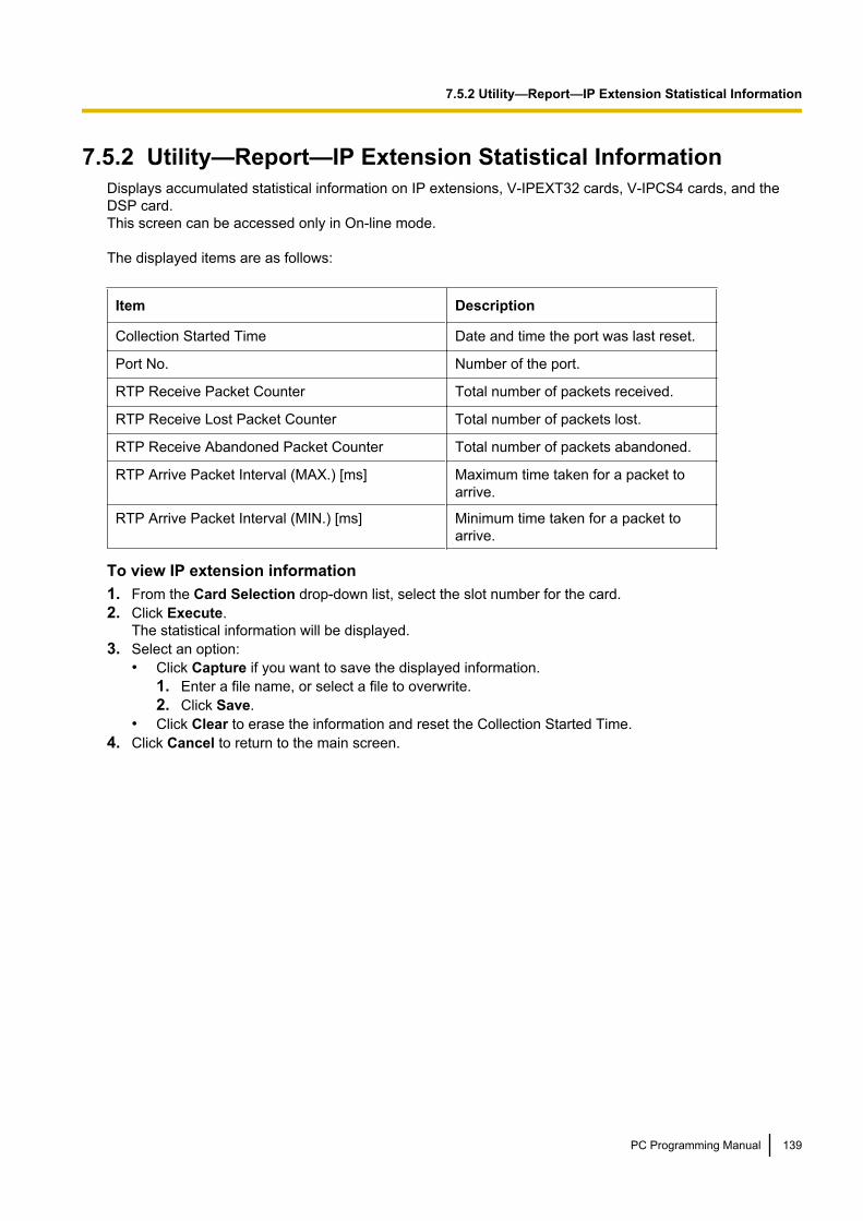
7.5.2 Utility—Report—IP Extension Statistical InformationDisplays accumulated statistical information on IP extensions, V-IPEXT32 cards, V-IPCS4 cards, and theDSP card.This screen can be accessed only in On-line mode.
The displayed items are as follows:
Item Description
Collection Started Time Date and time the port was last reset.
Port No. Number of the port.
RTP Receive Packet Counter Total number of packets received.
RTP Receive Lost Packet Counter Total number of packets lost.
RTP Receive Abandoned Packet Counter Total number of packets abandoned.
RTP Arrive Packet Interval (MAX.) [ms] Maximum time taken for a packet toarrive.
RTP Arrive Packet Interval (MIN.) [ms] Minimum time taken for a packet toarrive.
To view IP extension information1. From the Card Selection drop-down list, select the slot number for the card.2. Click Execute.
The statistical information will be displayed.3. Select an option:
• Click Capture if you want to save the displayed information.1. Enter a file name, or select a file to overwrite.2. Click Save.
• Click Clear to erase the information and reset the Collection Started Time.4. Click Cancel to return to the main screen.
PC Programming Manual 139
7.5.2 Utility—Report—IP Extension Statistical Information
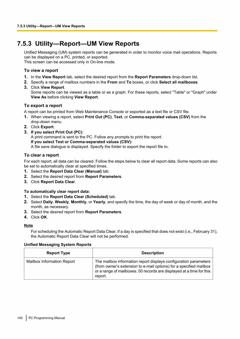
7.5.3 Utility—Report—UM View ReportsUnified Messaging (UM) system reports can be generated in order to monitor voice mail operations. Reportscan be displayed on a PC, printed, or exported.This screen can be accessed only in On-line mode.
To view a report1. In the View Report tab, select the desired report from the Report Parameters drop-down list.2. Specify a range of mailbox numbers in the From and To boxes, or click Select all mailboxes.3. Click View Report.
Some reports can be viewed as a table or as a graph. For these reports, select "Table" or "Graph" underView As before clicking View Report.
To export a reportA report can be printed from Web Maintenance Console or exported as a text file or CSV file.1. When viewing a report, select Print Out (PC), Text, or Comma-separated values (CSV) from the
drop-down menu.2. Click Export.3. If you select Print Out (PC):
A print command is sent to the PC. Follow any prompts to print the report.If you select Text or Comma-separated values (CSV):A file save dialogue is displayed. Specify the folder to export the report file to.
To clear a reportFor each report, all data can be cleared. Follow the steps below to clear all report data. Some reports can alsobe set to automatically clear at specified times.1. Select the Report Data Clear (Manual) tab.2. Select the desired report from Report Parameters.3. Click Report Data Clear.
To automatically clear report data:1. Select the Report Data Clear (Scheduled) tab.2. Select Daily, Weekly, Monthly, or Yearly, and specify the time, the day of week or day of month, and the
month, as necessary.3. Select the desired report from Report Parameters.4. Click OK.
NoteFor scheduling the Automatic Report Data Clear, if a day is specified that does not exist (i.e., February 31),the Automatic Report Data Clear will not be performed.
Unified Messaging System Reports
Report Type Description
Mailbox Information Report The mailbox information report displays configuration parameters(from owner’s extension to e-mail options) for a specified mailboxor a range of mailboxes. 50 records are displayed at a time for thisreport.
140 PC Programming Manual
7.5.3 Utility—Report—UM View Reports
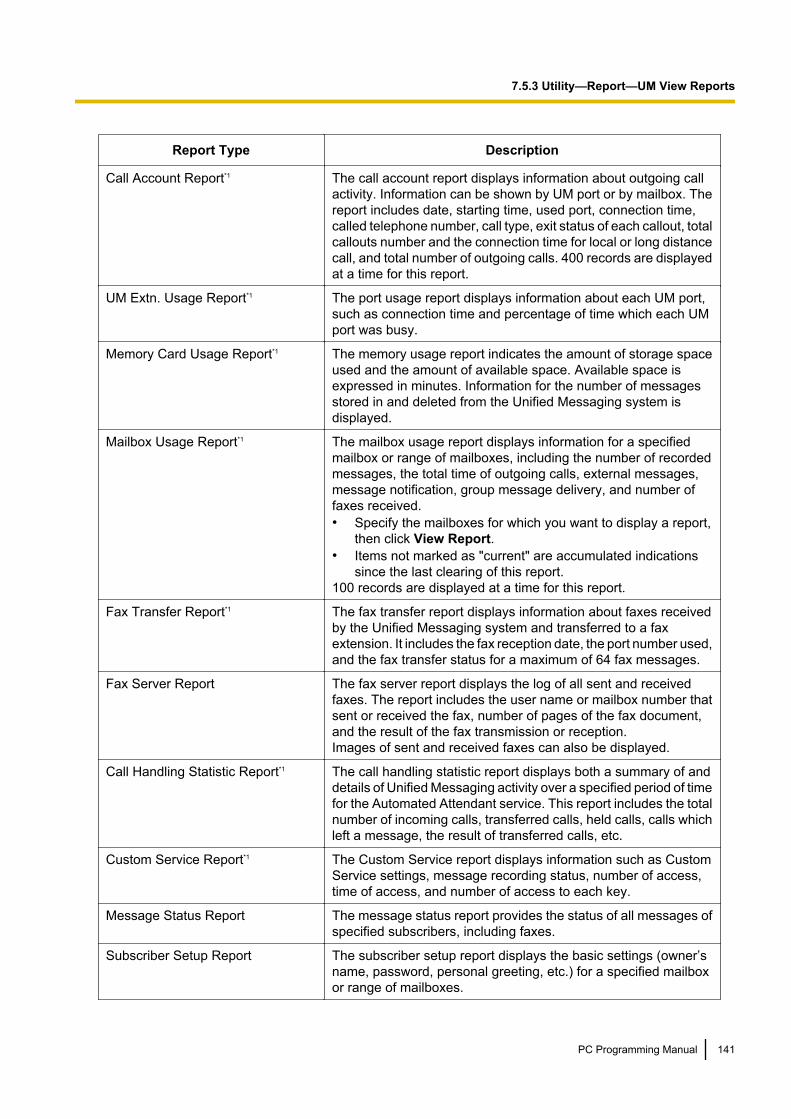
Report Type Description
Call Account Report*1 The call account report displays information about outgoing callactivity. Information can be shown by UM port or by mailbox. Thereport includes date, starting time, used port, connection time,called telephone number, call type, exit status of each callout, totalcallouts number and the connection time for local or long distancecall, and total number of outgoing calls. 400 records are displayedat a time for this report.
UM Extn. Usage Report*1 The port usage report displays information about each UM port,such as connection time and percentage of time which each UMport was busy.
Memory Card Usage Report*1 The memory usage report indicates the amount of storage spaceused and the amount of available space. Available space isexpressed in minutes. Information for the number of messagesstored in and deleted from the Unified Messaging system isdisplayed.
Mailbox Usage Report*1 The mailbox usage report displays information for a specifiedmailbox or range of mailboxes, including the number of recordedmessages, the total time of outgoing calls, external messages,message notification, group message delivery, and number offaxes received.• Specify the mailboxes for which you want to display a report,
then click View Report.• Items not marked as "current" are accumulated indications
since the last clearing of this report.100 records are displayed at a time for this report.
Fax Transfer Report*1 The fax transfer report displays information about faxes receivedby the Unified Messaging system and transferred to a faxextension. It includes the fax reception date, the port number used,and the fax transfer status for a maximum of 64 fax messages.
Fax Server Report The fax server report displays the log of all sent and receivedfaxes. The report includes the user name or mailbox number thatsent or received the fax, number of pages of the fax document,and the result of the fax transmission or reception.Images of sent and received faxes can also be displayed.
Call Handling Statistic Report*1 The call handling statistic report displays both a summary of anddetails of Unified Messaging activity over a specified period of timefor the Automated Attendant service. This report includes the totalnumber of incoming calls, transferred calls, held calls, calls whichleft a message, the result of transferred calls, etc.
Custom Service Report*1 The Custom Service report displays information such as CustomService settings, message recording status, number of access,time of access, and number of access to each key.
Message Status Report The message status report provides the status of all messages ofspecified subscribers, including faxes.
Subscriber Setup Report The subscriber setup report displays the basic settings (owner’sname, password, personal greeting, etc.) for a specified mailboxor range of mailboxes.
PC Programming Manual 141
7.5.3 Utility—Report—UM View Reports
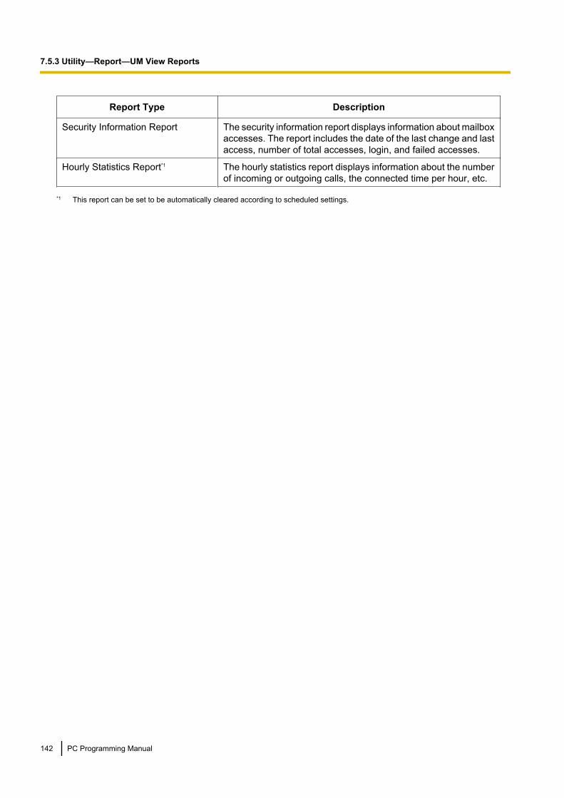
Report Type Description
Security Information Report The security information report displays information about mailboxaccesses. The report includes the date of the last change and lastaccess, number of total accesses, login, and failed accesses.
Hourly Statistics Report*1 The hourly statistics report displays information about the numberof incoming or outgoing calls, the connected time per hour, etc.
*1 This report can be set to be automatically cleared according to scheduled settings.
142 PC Programming Manual
7.5.3 Utility—Report—UM View Reports
7.5.4 Utility—Report—E-mail ReportA log of information about e-mail messages sent using the functions of the PBX can be viewed in the E-mailReport.This screen can be accessed only in On-line mode.The information in the report includes the following items for each e-mail message sent:• User name under which the message was sent• Unified Messaging mailbox number• Time sent• Destination e-mail address• Sending status of the e-mail message
The maximum number of entries included in the report is as follows, depending on the type of the message:• Voice mail or fax message notifications: 5,000 entries• Missed call notifications: 1,000 entries• Other e-mail messages (system messages, etc.): 1,000 entries
NoteMessages sent by the PBX, such as system alerts, will list the user as "System" and the mailbox numberas "—".
If these maximum amounts are exceeded, older records beyond the maximum amount for each type will bedeleted as new entries are recorded. To delete all e-mail report records, click Delete all E-mail report.
Exporting the E-mail Report1. Select an export format from the drop-down list.2. Click Export.3. A download dialogue for the e-mail report will be displayed. Open the file to view it, or save the file to the
PC.
PC Programming Manual 143
7.5.4 Utility—Report—E-mail Report
7.6 Utility—Activation Key InstallationActivation keys for various features of the PBX can be installed using this screen. Activation key files are copiedfrom a PC to the PBX and activated. Use the below procedure to install activation key files to a PBX.This screen can be accessed only in On-line mode.1. Click Browse and specify the directory where the activation key files are stored, and click Open.2. A list of activation key files stored in the specified directory is displayed. Check the boxes next to the
activation keys to install to the PBX, and click Install.3. The activation keys will be copied to the Master unit, and then copied to the Slave units of the One-look
network. When installation is complete, the message, "The activation key has been installed and activatedsuccessfully!" is displayed.
4. Click OK.
NoteYou can click the provided link to directly access 9.3 PBX Configuration—[1-1]Configuration—Slot—Activation Key Status to view activation key information and programme thenumber of activated IP-GW trunks and IP softphones.
144 PC Programming Manual
7.6 Utility—Activation Key Installation

7.7 Utility—Email Notification
7.7.1 Utility—Email Notification—AlertYou can specify e-mail addresses that will receive messages regarding the PBX’s status.
System AlarmAn e-mail message will be sent to the specified address when there is a system alarm. The e-mail messagewill contain details about the alarm.1. For Filtering Setting, select the check boxes to specify whether to receive e-mails when there is a Major
alarm, a Minor alarm, or both.2. Specify one or two e-mail addresses that will receive system alarm alert messages.
NoticeBe sure to enter e-mail addresses correctly. If an address is incorrectly entered, an alert will not bereceived when there is a system alarm, or information regarding the PBX may be sent unintentionallyto a third party.
3. In Subject enter the text that will be used for the subject header of e-mails that are sent.4. Click OK when finished.
Licence ExpiryWhen activation keys that are registered to the PBX and have a limited duration are about to expire, an e-mailmessage can be sent to the specified addresses. When 10 days remain in the duration of a registered activationkey, the e-mail will be sent.1. Specify one or two e-mail addresses that will receive expiry notice messages.
NoticeBe sure to enter e-mail addresses correctly. If an address is incorrectly entered, an alert will not bereceived when activation keys are about to expire, or information regarding the PBX may be sentunintentionally to a third party.
2. In Subject enter the text that will be used for the subject header of e-mails that are sent.3. Click OK when finished.
PC Programming Manual 145
7.7.1 Utility—Email Notification—Alert
7.7.2 Utility—Email Notification—System AnalysisSend a specific log file to the designated e-mail address(es).This screen can be accessed only in On-line mode.1. Check the Log File Type drop-down menu, select a log file to send to the e-mail address.2. Enter up to 2 e-mail addresses in Email Address 1 and Email Address 2.3. In Subject, enter text to be used as the subject line of the e-mail sent.4. Click Execute and the mail will be sent at that time.
146 PC Programming Manual
7.7.2 Utility—Email Notification—System Analysis

7.7.3 Utility—Email Notification—Test EmailSend a test e-mail to confirm e-mail sending settings are correctly configured.This screen can be accessed only in On-line mode.1. Enter up to 2 e-mail addresses in Email Address 1 and Email Address 2.2. In Subject, enter text to be used as the subject line of the e-mail sent.3. Click Execute. A test mail will be sent to the specified address(es).Mail settings can be viewed and set in 27.2.5 Network Service—[2-6] Server Feature—SMTP.
PC Programming Manual 147
7.7.3 Utility—Email Notification—Test Email

7.8 Utility—Command
7.8.1 Utility—Command—UM CommandSystem commands can be sent directly to the Unified Messaging system using the Commands dialogue.This screen can be accessed only in On-line mode.Follow the steps below to use the Commands dialogue:1. Enter the desired command, then click RUN. Results from entered commands are displayed.2. When finished, click Close.
148 PC Programming Manual
7.8.1 Utility—Command—UM Command
7.9 Utility—UM – System Prompts CustomisationThe System Prompts customisation screen is used to view, play, add, or delete system prompts. Theprogrammer can also check the prompt number and text for these prompts.This screen can be accessed only in On-line mode.The following categories of system prompts can be customised from the System Prompts customisationscreen:a. System Guidanceb. Custom Service Menusc. Company Greetingsd. Other
– Company Name– Language Select Menu– Hold Announce Menu– Mailbox Group List– System Caller ID
To customise system prompts, select a tab in the System Prompts dialogue box.
NoticeThe system prompts initially installed on the Storage Memory Card cannot be restored to their original stateby initialising or resetting the PBX; any changes made to the initially installed system prompts cannot beundone. Before changing any system prompts, perform a backup of the initial system prompt data. See6.9 Tool—UM Data Backup for details. Then, you can restore the system prompts to their initial state byrestoring the backup data. See 6.10 Tool—UM Data Restore for details.
Deleting PromptsThe programmer is able to delete specified system prompts.To delete a specific system prompt:1. Select the cell for the desired prompt number.2. Click Delete.
Recording System Prompts1. Select the desired system prompt to record, and click Play/Record.2. Select "Record from extension" or "Import from recorded file".
When "Record from extension" is selected:1. Specify the extension number of the telephone used for recording, then click Connect.2. When the specified extension rings, go off-hook.3. Click Record, Stop, or Play to record or play a system prompt.4. Click Disconnect.5. Click OK.When "Import from recorded file" is selected:1. Click Browse.
The Open dialogue box appears.2. Navigate to the folder containing the WAV files you wish to import.
WAV files must meet the following specifications:– G.711 PCM codec– 8 kHz, 8-bit sampling rate– Monaural– A-law or µ-law encoding
3. Select the desired WAV file.4. Click Open to import the file.5. Click OK.
PC Programming Manual 149
7.9 Utility—UM – System Prompts Customisation

Starting and Stopping System Prompt Playback1. Select the desired system prompts.2. Click Play/Record.3. Click Play or Stop.
150 PC Programming Manual
7.9 Utility—UM – System Prompts Customisation
7.10 Utility—Automatic Two-way Recording
7.10.1 Utility—Automatic Two-way Recording—SupervisorSetting
Specify the extensions of supervisors that will control the Automatic Two-way Recording feature for agentextensions. These settings may be changed by a programmer with a User (Administrator) account.1. Click Add/Delete.2. Select supervisor extensions from the list, and click OK.3. Repeat this procedure to add multiple supervisors. Click OK when finished.
PC Programming Manual 151
7.10.1 Utility—Automatic Two-way Recording—Supervisor Setting

7.10.2 Utility—Automatic Two-way Recording—Extension SettingSpecify the Automatic Two-way Recording settings for each supervisor. These settings may be changed by aprogrammer with a User (Administrator) account.1. From the Select a Supervisor drop-down list, select a supervisor (specified in 7.10.1 Utility—Automatic
Two-way Recording—Supervisor Setting).2. In UM Group Destination Mailbox specify the mailbox where the Automatic Two-way Recording data will
be sent. Select Add New Mailbox and specify a new mailbox number, or select an existing mailbox fromthe Select Mailbox drop-down list.
3. Select a UM group from the Assign a Destination UM-Group No. drop-down list to specify the UM Groupof the mailbox specified in 2.
4. In What type of calls to record, check the boxes to specify if internal calls, external calls, and/or callsmade to an incoming call distribution group will be recorded to the mailbox.
5. In Select User Extensions, click Add.6. Select the check boxes for the agent extensions that the supervisor will control, and then click OK.7. Click List View to confirm the current Automatic Two-way Recording settings for each supervised
extension.8. Click OK when you have finished configuring settings and adding agent extensions for a supervisor.Once these settings have been configured, supervisors can change settings for agent extensions they havebeen assigned in 8.3.1 Users—Automatic Two-way Recording—Edit a Recording.
152 PC Programming Manual
7.10.2 Utility—Automatic Two-way Recording—Extension Setting
7.10.3 Utility—Automatic Two-way Recording—Extension SettingList
In this list you can view the settings of extensions that are programmed to have calls recorded by the AutomaticTwo-way Recording feature. Information for each extension, including the extension’s supervisor, UM Groupnumber, and Automatic Two-way Recording destination mailbox is displayed.You can specify which types of calls will recorded for each extension. These settings may be changed by aprogrammer with a User (Administrator) account.1. For an extension, select a setting for Internal Call, External Call, and ICDG Incoming Only. (See below
for details.)• Internal Call: Extension-to-extension calls are recorded.• External Call: Calls with outside parties are recorded.• ICDG Incoming Only: Only calls that are received by the extension through an incoming call
distribution group are recorded.2. Select On or Off for that setting.3. Click OK when finished.The programming items displayed on this screen are as follows.
Extension NumberIndicates the extension number of the extension (reference only).
Value RangeMax. 5 digits (consisting of 0–9)
Maintenance Console Location7.10.3 Utility—Automatic Two-way Recording—Extension Setting List
Extension NameIndicates the name of the extension (reference only).
Value RangeMax. 20 characters
Maintenance Console Location7.10.3 Utility—Automatic Two-way Recording—Extension Setting List
Internal CallSpecifies whether intercom calls for the extension will be automatically recorded.
NoteCalls between extensions that are connected in a QSIG network are seen as external calls, irrespective ofwhether an activation key for QSIG enhanced features is used. To enable Automatic Two-way Recordingfor this type of call, set External Call to On.
Value RangeOn, Off
PC Programming Manual 153
7.10.3 Utility—Automatic Two-way Recording—Extension Setting List

Maintenance Console Location7.10.3 Utility—Automatic Two-way Recording—Extension Setting List
Feature Guide References3.2.1.4 Automatic Two-way Recording for Manager
External CallSpecifies whether trunk calls for the extension are automatically recorded.
Value RangeOn, Off
Maintenance Console Location7.10.3 Utility—Automatic Two-way Recording—Extension Setting List
Feature Guide References3.2.1.4 Automatic Two-way Recording for Manager
ICDG Incoming OnlySpecifies whether only trunk calls that are received through an incoming call distribution group to the extensionare automatically recorded.
NoteExternal Call must be set to "On" to set this item to "On".
Value RangeOn, Off
Maintenance Console Location7.10.3 Utility—Automatic Two-way Recording—Extension Setting List
Feature Guide References3.2.1.4 Automatic Two-way Recording for Manager
SupervisorIndicates the extension designated as a supervisor that may play, delete, or confirm the information of two-wayrecordings (reference only).
Value RangeExtension number and user name
Maintenance Console Location7.10.3 Utility—Automatic Two-way Recording—Extension Setting List
154 PC Programming Manual
7.10.3 Utility—Automatic Two-way Recording—Extension Setting List

PC Programming Manual References7.10.1 Utility—Automatic Two-way Recording—Supervisor Setting
Feature Guide References3.2.1.4 Automatic Two-way Recording for Manager
UM Group No.Indicates the UM group number in which the two-way recording will be performed (reference only).
Value RangeGroup number and group name
Maintenance Console Location7.10.3 Utility—Automatic Two-way Recording—Extension Setting List
PC Programming Manual References7.10.2 Utility—Automatic Two-way Recording—Extension Setting
Feature Guide References3.2.1.4 Automatic Two-way Recording for Manager
Mailbox NumberIndicates the Unified Messaging mailbox where two-way recordings will be stored (reference only).
Value RangeMailbox number
Maintenance Console Location7.10.3 Utility—Automatic Two-way Recording—Extension Setting List
PC Programming Manual References7.10.2 Utility—Automatic Two-way Recording—Extension Setting
Feature Guide References3.2.1.4 Automatic Two-way Recording for Manager
PC Programming Manual 155
7.10.3 Utility—Automatic Two-way Recording—Extension Setting List
7.10.4 Utility—Automatic Two-way Recording—MaintenanceAutomatic Two-way Recording can be enabled or disabled, or set to record until a specified date and time bya programmer with a User (Administrator) account.1. To start Automatic Two-way Recording, click Start. The button will change to display Stop.
Two-way recording for all designated extensions will continue until one of the following occurs:• The Stop button is clicked.• The two-way recording time limit or memory capacity has been reached.• The date and time set in Recording Period is reached.
2. To set a specific time when Automatic Two-way Recording will stop:a. In Recording Period, select Yes for Setting.b. In Date & Time, enter a year, month, day, hour, and minute. Click on the calendar and clock numbers
to select them.c. Click OK.
3. To end Automatic Two-way Recording any time, click Stop.
156 PC Programming Manual
7.10.4 Utility—Automatic Two-way Recording—Maintenance
7.11 Utility—UM - System MaintenanceProgramme settings for Unified Messaging (UM) system maintenance.
System Maintenance ModeSpecifies whether to enable or disable System Maintenance Mode.
System Maintenance Start TimeSpecifies the System Maintenance start time.
After specifying the settings on this screen, click OK.
PC Programming Manual 157
7.11 Utility—UM - System Maintenance

7.12 Utility—CS-Web ConnectionYou can specify the URL of the Super Master CS for your system, which will be used for accessing onlineCS-Web system programming. For details about the Super Master CS and setting up SIP-CSs, refer to theSIP-CS Installation Guide.1. In Super Master CS-Web URL, enter the URL of the Super Master CS.2. Click Test to confirm if the input URL is correct. If the URL is correct, the CS-Web login screen will open
in your web browser.3. Click OK.When programming in other screens, clicking the SIP-CS Web button on that screen will access CS-Websystem programming at the URL specified here.
158 PC Programming Manual
7.12 Utility—CS-Web Connection

Section 8
Users
This section serves as reference operating instructionsfor the Users menu of the Setup screen of WebMaintenance Console.
PC Programming Manual 159

8.1 Users—User ProfilesManage PBX settings on a per-user level. Information for each user account is displayed and can be added,edited, or and deleted by a User (Administrator) or Installer level account.
NoteFor User (Administrator) accounts to change User (User) account settings, the Installer account must usethe Screen Customise tool to allow User (Administrator) accounts to view the Users—User Profiles screen.For details, see 6.8 Tool—Screen Customise.
The settings that can be changed in the User Profile List for each user are as follows:
Common
Item Description
First Name Specifies the first name of the user.
Last Name Specifies the last name of the user.
User Group Specifies the user’s group.User groups can be set in Extension Settings:• 12.1.1 PBX Configuration—[4-1-1] Extension—Wired
Extension—Extension Settings• 12.2.1 PBX Configuration—[4-2-1] Extension—Portable
Station—Extension Settings
Ext. No. Specifies the extension number associated with this user.Extension numbers can be set in Extension Settings:• 12.1.1 PBX Configuration—[4-1-1] Extension—Wired
Extension—Extension Settings• 12.2.1 PBX Configuration—[4-2-1] Extension—Portable
Station—Extension Settings
Ext. COS Select a Class of Service (COS) for the user from the drop-down list.COS settings can be set in 10.7 PBX Configuration—[2-7] System—Class ofService.
UM Group No. Select a UM group for the user from the drop-down list.
Mailbox No. Specifies the UM mailbox number for the user.
Mailbox COS Select a mailbox COS for the user from the drop-down list. Mailbox COS settingscan be set in 21.1 UM Configuration—[2] Class of Service.
FWD/DND
Item Description
First Name Specifies the first name of the user.
Last Name Specifies the last name of the user.
FWD/DND setting - call from COMode
Specifies the FWD/DND setting for calls from trunks.
FWD setting - call from CODestination
Specifies the FWD destination for calls from trunks.
FWD/DND setting - call from Ext.Mode
Specifies the FWD/DND setting for calls from extensions.
160 PC Programming Manual
8.1 Users—User Profiles
Item Description
FWD setting - call from Ext.Destination
Specifies the FWD destination for calls from extensions.
For settings and details for FWD/DND items, refer to the following:• 12.1.2 PBX Configuration—[4-1-2] Extension—Wired Extension—FWD/DND• 12.2.2 PBX Configuration—[4-2-2] Extension—Portable Station—FWD/DND
NoteWhen a User (User) level account accesses this screen, he may view and edit items for his account asexplained in 8.2.1 Users—Add User—Single User. In addition, some advanced settings are availablefor User (User) level accounts only. For details, see 8.1.1 Users—User Profiles—Advanced setting.
User Controls• Add Button
To add a user profile for a single extension, click the button to open the Add User Wizard. See8.2.1 Users—Add User—Single User.
• Edit ButtonTo edit information on an individual user level, select a user from the list by clicking on the row of the userto edit, then clicking the button to open the Add User Wizard with the selected user’s information filledin. See 8.2.1 Users—Add User—Single User.
• Delete ButtonTo delete users:1. Check the box(es) next to the user’s name(s) and click the button.2. A confirmation message will appear. Click OK.3. The user’s information is deleted from the list.
• Add Range ButtonTo add multiple user profiles for a range of extensions at one time, click the button. See8.2.2 Users—Add User—Multiple Users.
Note• In order to edit the settings of the Unified Message tab by clicking the button, you must be logged
in to the PBX with the associated UM Group that your mailbox is assigned to. If you are logged in to aPBX that is different from the PBX with the associated UM Group of your mailbox, the following itemswill be greyed out:– Prompt Registration– Mailbox Password– Mailbox Password (Message client)– Advanced settingIf these items are greyed out, click Direct Login to log in directly to the PBX associated with the UMGroup of your mailbox to make changes to these items.
• The , , and buttons are not visible for User (User) level accounts.
PC Programming Manual 161
8.1 Users—User Profiles

8.1.1 Users—User Profiles—Advanced settingWhen User (User) level accounts access their user profiles, they may view and edit items for their account asexplained in 8.2.1 Users—Add User—Single User. In addition, some advanced settings can also beprogrammed by users.
NoteThe advanced settings described here are displayed only for User (User) level accounts.
Accessing advanced user profile settings1. Log in Web Maintenance Console using a User (User) level account.2. In the user profile, click the Unified Message tab.3. Click the Advanced setting button.4. In addition to normal mailbox settings, Advanced Call Transfer Setting and Scenario Setting will be
displayed.
Advanced Call Transfer SettingBy combining the settings for Call Transfer and Incomplete Call Handling, you can create a call handling"scenario" for your extension. Up to 20 scenarios can be created, and a scenario can be assigned to eachabsent message. Click the Edit button in Advanced Call Transfer Setting to open the window forprogramming. Select a Scenario number (1–20) from the drop-down menu, then programme the settings forthat scenario. Click OK at the bottom of the window when finished.
Scenario NameSpecify a name for the scenario for identification.
Value RangeMax. 32 Characters
Maintenance Console Location8.1.1 Users—User Profiles—Advanced setting
Feature Guide References3.2.2.7 Call Transfer Scenario
Call Transfer Status—SelectionDetermines how the Unified Messaging system will handle a call in the selected scenario.
Value RangeNone: Rings the subscriber’s extension.Call blocking: Handles the call according to the Incomplete Call Handling for No Answer setting for thesubscriber’s extension. The subscriber’s extension will not ring.Call screening: The caller is prompted to record his or her name. The Unified Messaging system then callsthe subscriber and plays back the caller name. The subscriber can choose whether to answer the call.Leave a Message: Transfers the caller to the mailbox.Intercom Paging: Pages the subscriber by intercom.Transfer to specified Custom Service Menu: Transfers the caller to the specified Custom Service.
162 PC Programming Manual
8.1.1 Users—User Profiles—Advanced setting
Maintenance Console Location8.1.1 Users—User Profiles—Advanced setting
Feature Guide References3.2.2.7 Call Transfer Scenario
Call Transfer Status—VIP FilterSpecifies whether calls from certain telephone numbers will be transferred directly to a specified extension ortelephone number.
NoteThis setting can only be set to "Enable" when Call Transfer Status—Selection is set to "Leave aMessage".
Value RangeEnable, Disable
Maintenance Console Location8.1.1 Users—User Profiles—Advanced setting
Feature Guide References3.2.2.7 Call Transfer Scenario
Call Transfer Status—Telephone Number 1, 2, 3Specifies the telephone numbers that the VIP Filter setting will be applied to. When a call is received from anyof the numbers specified here, the call will be transferred immediately to the destination specified in CallTransfer Status—Transfer to (Selection/Other).
Value RangeMax. 32 digits
Maintenance Console Location8.1.1 Users—User Profiles—Advanced setting
Feature Guide References3.2.2.7 Call Transfer Scenario
Call Transfer Status—Transfer to (Selection/Other)Specifies the transfer destination for calls transferred according to the VIP Filter setting.
Value RangeExtension: The call is transferred to the user’s extension.Other: The call is transferred to the telephone number that is specified in Transfer to (Other).
PC Programming Manual 163
8.1.1 Users—User Profiles—Advanced setting

Maintenance Console Location8.1.1 Users—User Profiles—Advanced setting
Feature Guide References3.2.2.7 Call Transfer Scenario
Call Transfer Status—Transfer to specified Custom Service MenuSelect a Custom Service from the drop-down menu if "Transfer to specified Custom Service Menu" is selectedfor Call Transfer Status—Selection.
Value RangeCustom Service
Maintenance Console Location8.1.1 Users—User Profiles—Advanced setting
PC Programming Manual References23.3 UM Configuration—[4-3] Service Settings—Custom Service
Feature Guide References3.2.2.7 Call Transfer Scenario
Call Transfer Status—Transfer to specified telephone number - 1If "None" or "Call screening" is selected for Call Transfer Status—Selection, specifying a telephone numberhere will transfer the caller to that telephone number.
NoteIf "Call screening" is selected, the transfer destination will hear the call screening prompt before the call istransferred.
Value RangeMax. 32 digits (consisting of 0–9, , and #)
Maintenance Console Location8.1.1 Users—User Profiles—Advanced setting
Feature Guide References3.2.2.7 Call Transfer Scenario
164 PC Programming Manual
8.1.1 Users—User Profiles—Advanced setting
Call Transfer Status—Transfer to specified telephone number 2, 3, 4, 5(Selection/Other)
If "None" or "Call screening" is selected for Call Transfer Status—Selection, and the call could not betransferred to the number specified in Call Transfer Status—Transfer to specified telephone number -1, the call will be transferred according to these settings for this scenario, in numerical order of priority.
Note• This sequence has higher priority than the alternate extension transfer sequence specified in 24.4 UM
Configuration—[5-4] System Parameters—Parameters— PBX Environment—AlternateExtension Transfer Sequence (Up to 16 digits / [0-9 * # D R F T X , ;]).
• If "Call screening" is selected, the transfer destination will hear the call screening prompt before thecall is transferred.
Value RangeOther, Extension, Covering ExtensionIf "Other" is specified, enter a maximum of 32 digits consisting of 0–9, , and #.
Maintenance Console Location8.1.1 Users—User Profiles—Advanced setting
Feature Guide References3.2.2.7 Call Transfer Scenario
Incomplete Call Handling for No AnswerSpecifies how the scenario handles a call when there is no answer.
NoteMore than one option can be selected.
Value RangeLeave a Message: Allows the caller to record a message.Transfer to a covering extension: Transfers the caller to a covering extension.Page the mailbox owner by intercom paging: Pages the subscriber by intercom.Transfer to operator: Transfers the caller to an operator.Return to top menu: Lets the caller return to the top menu and try another extension.Transfer to specified Custom Service Menu: Transfers the caller to the specified Custom Service.
Maintenance Console Location8.1.1 Users—User Profiles—Advanced setting
Feature Guide References3.2.2.7 Call Transfer Scenario
Incomplete Call Handling for BusySpecifies how the scenario handles a call when the destination is busy.
PC Programming Manual 165
8.1.1 Users—User Profiles—Advanced setting
NoteMore than one option can be selected.
Value RangeLeave a Message: Allows the caller to record a message.Transfer to a covering extension: Transfers the caller to a covering extension.Page the mailbox owner by intercom paging: Pages the subscriber by intercom.Transfer to operator: Transfers the caller to an operator.Return to top menu: Lets the caller return to top menu and try another extension.Transfer to specified Custom Service Menu: Transfers the caller to the specified Custom Service.
Maintenance Console Location8.1.1 Users—User Profiles—Advanced setting
Feature Guide References3.2.2.7 Call Transfer Scenario
Scenario SettingYou can select scenarios set in 8.1.1 Users—User Profiles—Advanced setting for your extension. A scenariocan be set temporarily, or scenarios can be selected for use according to the Absent Message setting of theextension of the subscriber. (® 14.5 PBX Configuration—[6-5] Feature—Absent Message)Temporary Scenario: Setting a scenario here will use that scenario indefinitely. A scenario set here will beused regardless of the subscriber’s extension status. Selecting "None" will remove the setting.Absent Message 1–9: The selected scenario will be used when the indicated Absent Message is set at theextension.
166 PC Programming Manual
8.1.1 Users—User Profiles—Advanced setting
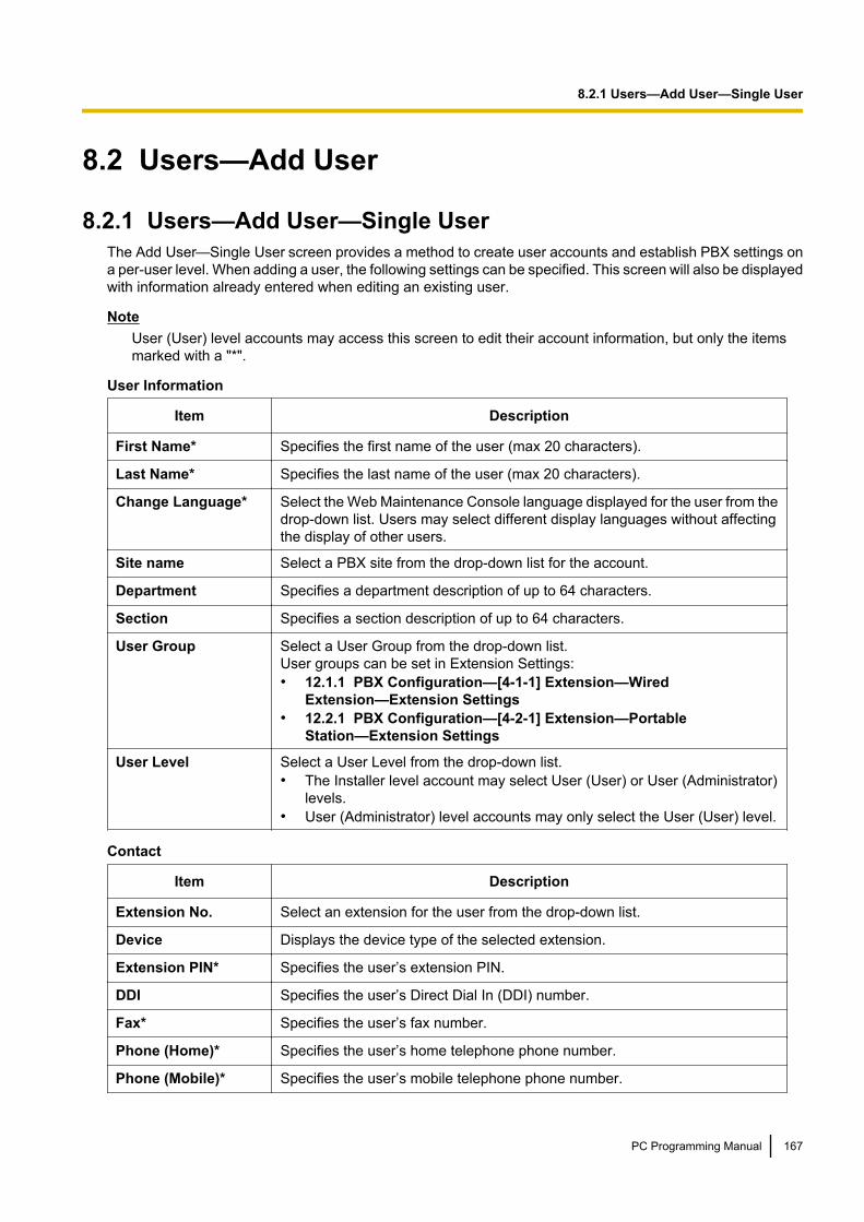
8.2 Users—Add User
8.2.1 Users—Add User—Single UserThe Add User—Single User screen provides a method to create user accounts and establish PBX settings ona per-user level. When adding a user, the following settings can be specified. This screen will also be displayedwith information already entered when editing an existing user.
NoteUser (User) level accounts may access this screen to edit their account information, but only the itemsmarked with a "*".
User Information
Item Description
First Name* Specifies the first name of the user (max 20 characters).
Last Name* Specifies the last name of the user (max 20 characters).
Change Language* Select the Web Maintenance Console language displayed for the user from thedrop-down list. Users may select different display languages without affectingthe display of other users.
Site name Select a PBX site from the drop-down list for the account.
Department Specifies a department description of up to 64 characters.
Section Specifies a section description of up to 64 characters.
User Group Select a User Group from the drop-down list.User groups can be set in Extension Settings:• 12.1.1 PBX Configuration—[4-1-1] Extension—Wired
Extension—Extension Settings• 12.2.1 PBX Configuration—[4-2-1] Extension—Portable
Station—Extension Settings
User Level Select a User Level from the drop-down list.• The Installer level account may select User (User) or User (Administrator)
levels.• User (Administrator) level accounts may only select the User (User) level.
Contact
Item Description
Extension No. Select an extension for the user from the drop-down list.
Device Displays the device type of the selected extension.
Extension PIN* Specifies the user’s extension PIN.
DDI Specifies the user’s Direct Dial In (DDI) number.
Fax* Specifies the user’s fax number.
Phone (Home)* Specifies the user’s home telephone phone number.
Phone (Mobile)* Specifies the user’s mobile telephone phone number.
PC Programming Manual 167
8.2.1 Users—Add User—Single User
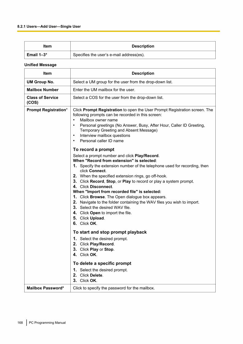
Item Description
Email 1–3* Specifies the user’s e-mail address(es).
Unified Message
Item Description
UM Group No. Select a UM group for the user from the drop-down list.
Mailbox Number Enter the UM mailbox for the user.
Class of Service(COS)
Select a COS for the user from the drop-down list.
Prompt Registration* Click Prompt Registration to open the User Prompt Registration screen. Thefollowing prompts can be recorded in this screen:• Mailbox owner name• Personal greetings (No Answer, Busy, After Hour, Caller ID Greeting,
Temporary Greeting and Absent Message)• Interview mailbox questions• Personal caller ID name
To record a promptSelect a prompt number and click Play/Record.When "Record from extension" is selected:1. Specify the extension number of the telephone used for recording, then
click Connect.2. When the specified extension rings, go off-hook.3. Click Record, Stop, or Play to record or play a system prompt.4. Click Disconnect.When "Import from recorded file" is selected:1. Click Browse. The Open dialogue box appears.2. Navigate to the folder containing the WAV files you wish to import.3. Select the desired WAV file.4. Click Open to import the file.5. Click Upload.6. Click OK.
To start and stop prompt playback1. Select the desired prompt.2. Click Play/Record.3. Click Play or Stop.4. Click OK.
To delete a specific prompt1. Select the desired prompt.2. Click Delete.3. Click OK.
Mailbox Password* Click to specify the password for the mailbox.
168 PC Programming Manual
8.2.1 Users—Add User—Single User
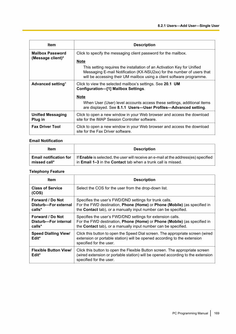
Item Description
Mailbox Password(Message client)*
Click to specify the messaging client password for the mailbox.
NoteThis setting requires the installation of an Activation Key for UnifiedMessaging E-mail Notification (KX-NSU2xx) for the number of users thatwill be accessing their UM mailbox using a client software programme.
Advanced setting* Click to view the selected mailbox’s settings. See 20.1 UMConfiguration—[1] Mailbox Settings.
NoteWhen User (User) level accounts access these settings, additional itemsare displayed. See 8.1.1 Users—User Profiles—Advanced setting.
Unified MessagingPlug in
Click to open a new window in your Web browser and access the downloadsite for the IMAP Session Controller software.
Fax Driver Tool Click to open a new window in your Web browser and access the downloadsite for the Fax Driver software.
Email Notification
Item Description
Email notification formissed call*
If Enable is selected, the user will receive an e-mail at the address(es) specifiedin Email 1–3 in the Contact tab when a trunk call is missed.
Telephony Feature
Item Description
Class of Service(COS)
Select the COS for the user from the drop-down list.
Forward / Do NotDisturb—For externalcalls*
Specifies the user’s FWD/DND settings for trunk calls.For the FWD destination, Phone (Home) or Phone (Mobile) (as specified inthe Contact tab), or a manually input number can be specified.
Forward / Do NotDisturb—For internalcalls*
Specifies the user’s FWD/DND settings for extension calls.For the FWD destination, Phone (Home) or Phone (Mobile) (as specified inthe Contact tab), or a manually input number can be specified.
Speed Dialling View/Edit*
Click this button to open the Speed Dial screen. The appropriate screen (wiredextension or portable station) will be opened according to the extensionspecified for the user.
Flexible Button View/Edit*
Click this button to open the Flexible Button screen. The appropriate screen(wired extension or portable station) will be opened according to the extensionspecified for the user.
PC Programming Manual 169
8.2.1 Users—Add User—Single User
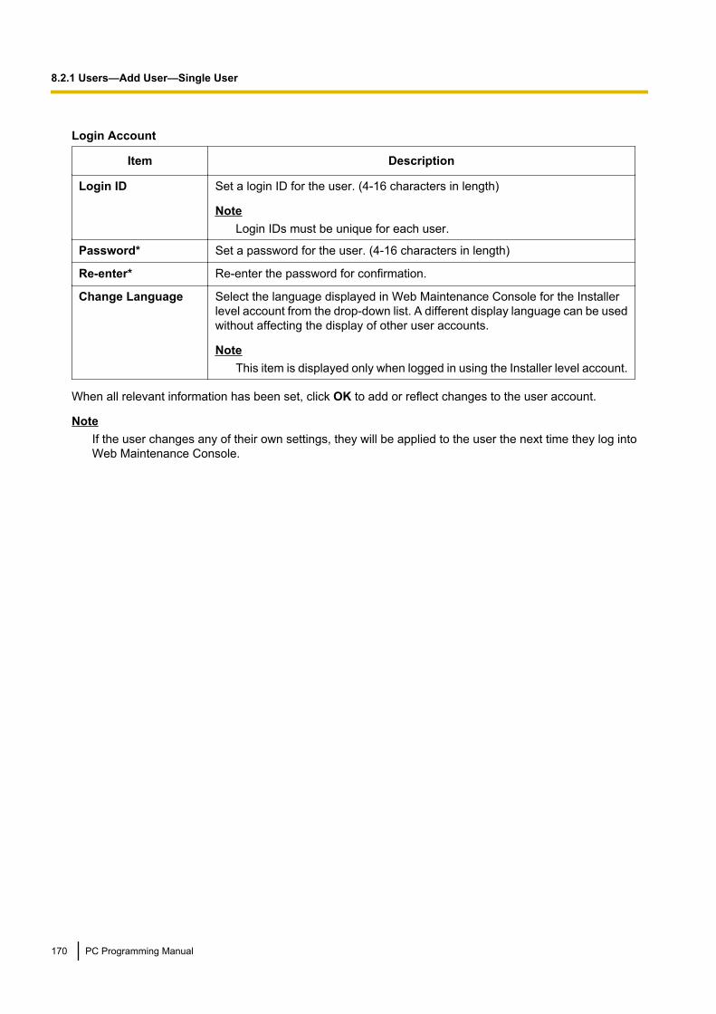
Login Account
Item Description
Login ID Set a login ID for the user. (4-16 characters in length)
NoteLogin IDs must be unique for each user.
Password* Set a password for the user. (4-16 characters in length)
Re-enter* Re-enter the password for confirmation.
Change Language Select the language displayed in Web Maintenance Console for the Installerlevel account from the drop-down list. A different display language can be usedwithout affecting the display of other user accounts.
NoteThis item is displayed only when logged in using the Installer level account.
When all relevant information has been set, click OK to add or reflect changes to the user account.
NoteIf the user changes any of their own settings, they will be applied to the user the next time they log intoWeb Maintenance Console.
170 PC Programming Manual
8.2.1 Users—Add User—Single User

8.2.2 Users—Add User—Multiple UsersThe Add User—Multiple Users screen provides a method to create multiple user profiles for a range ofextensions at one time.1. In the From and To fields, specify the range of extensions to create profiles for.2. Select the Create mailboxes with the same number as the extensions check box if you want to create
Unified Messaging mailboxes whose mailbox numbers are the same as the assigned extension numbers.3. If you choose to create mailboxes in step 2, select where the mailboxes will be created:
• Create mailboxes to the UM group of the PBX where extensions belong to:The mailbox for each extension will be created in the UM group of the site (PBX) to which the extensionis assigned.
NoteWhen this setting is selected, mailboxes for PS extensions will be created in the UM group of theMaster unit.
• Create mailboxes to the specified UM group:Mailboxes for the extensions will be created in the UM group that you select from the drop-down list.
4. Click OK.
Settings automatically programmed for each user• First Name: "Ext." + the extension number for the user (e.g., "Ext.101")• Last Name: The information entered in Extension Name for the extension in Section 12 PBX
Configuration—[4] Extension (If no information has been entered for the extension, this field will be leftblank.)
• Login ID: The extension number (i.e., if the extension is "101", the Login ID for the user will also be"101")
• Password: "PWD" + the extension number for the user (e.g., "PWD101")
Note• When OK is clicked, if any extensions within the range specified in step 1 already have user accounts
associated with them, the process will not complete, and an error message will be displayed.• If the Create mailboxes with the same number as the extensions check box is selected and a
mailbox number has already been assigned to another extension, the user profile will be created withouta UM mailbox assigned to it.
• If the maximum number of digits for a mailbox number ( Mailbox No. Max. Length (3-8) in 24.4 UMConfiguration—[5-4] System Parameters—Parameters) is less than the number of digits for thespecified extensions, the maximum number of digits for a mailbox number will be automaticallyincreased to match the number of digits for the specified extensions.
• A maximum of 500 users can be created at once using this feature.
PC Programming Manual 171
8.2.2 Users—Add User—Multiple Users
8.3 Users—Automatic Two-way RecordingThis screen is accessible only by users designated as Automatic Two-way Recording supervisors. See7.10.1 Utility—Automatic Two-way Recording—Supervisor Setting.This screen can be accessed only in On-line mode.
8.3.1 Users—Automatic Two-way Recording—Edit a RecordingOn this screen, a user designated as a supervisor may change Automatic Two-way Recording settings forextensions they are supervising. Information for each extension, including the extension’s supervisor, UMGroup number, and Automatic Two-way Recording destination mailbox is displayed.You can specify which types of calls will recorded for each extension.1. For an extension, click the setting for Internal Call, External Call, or ICDG Incoming Only.
• Internal Call: Extension-to-extension calls are recorded.• External Call: Calls with outside parties are recorded.• ICDG Incoming Only: Only calls that are received by the extension through an incoming call
distribution group are recorded.2. Select On or Off for that setting.
NoteTo set ICDG Incoming Only to "On", External Call must first be set to "On".
3. Click OK when finished.
172 PC Programming Manual
8.3.1 Users—Automatic Two-way Recording—Edit a Recording
8.3.2 Users—Automatic Two-way Recording—Record ListUsers designated as supervisors can view and play messages recorded using the Automatic Two-wayRecording feature.1. Select a UM group number from the Select a Destination UM-Group No. drop-down list.2. Click List View to display a list of the Automatic Two-way Recording mailboxes of the selected UM group.3. Select one or more mailboxes, and click OK.4. Messages recorded in the selected mailbox(es) will be displayed. You can filter the list of messages
displayed or play a message.To filter the list of messages:Specify any number of the following conditions, and then click Search to display the messages that matchthose conditions.• Mailbox: Specify an Automatic Two-way Recording mailbox, or select ALL.• Extension: Specify an extension to view all calls that were recorded using Automatic Two-way
Recording for that extension, or select ALL.• Status: Specify the status for the recorded messages in the mailbox.• Internal/External: Specify whether the recorded conversations were intercom calls or trunk calls, or
specify both.• Call Type: Specify whether the recorded conversations were incoming calls or outgoing calls, or specify
both.– If Internal/External is set to "Internal" or "Both", Call Type will be set to "Both".– If Internal/External is set to "External", Call Type can be set to "Incoming", "Outgoing", or
"Both".• Phone Number: Specify the phone number of the party calling the recorded extension.• Caller Name: Specify the name of the party that called the recorded extension (may not be available
for all recorded messages).• Length: Specify the length of the recorded conversations.• Period: Specify a time period in which calls were recorded.
To play a message:For playback on the PC:1. Select the check box of a message to play.2. At the bottom of the screen, select PC.3. Click the button.The message will be downloaded as an audio file for playback on the PC being used to connect to WebMaintenance Console.For playback using the supervisor’s designated extension:1. In the Mailbox filter, select the mailbox whose messages you want to display, and then click Search.2. Select the check boxes for one or more messages to play.3. At the bottom of the screen, select Phone.4. Click the button.
NoteIf ALL has been selected for the Mailbox filter, the button will be disabled. Select a specificmailbox to enable the button.
5. In the window that appears, enter the extension number in Specify Extension of the extension at whichto play back the messages, and then click Connect.
6. Go off-hook when the extension rings to establish a call with the UM message playback system.7. During the call, click Play to listen to the currently selected message. If multiple messages were
selected in step 2, you can click Prev and Next to cycle through and listen to the selected messages.8. When you are finished listening to messages, click Disconnect or go on-hook.
PC Programming Manual 173
8.3.2 Users—Automatic Two-way Recording—Record List

174 PC Programming Manual
8.3.2 Users—Automatic Two-way Recording—Record List

Section 9
PBX Configuration—[1] Configuration
This section serves as reference operating instructionsfor the Configuration menu of the PBX Configurationmenu of the Setup screen of Web MaintenanceConsole.
PC Programming Manual 175
9.1 PBX Configuration—[1-1] Configuration—SlotThe operating characteristics associated with each service card can be programmed.Move the mouse pointer over an installed card to display the menu of options for that card. To view a summaryof status and versions for all cards installed in the PBX, click the Summary button (see 9.2 PBXConfiguration—[1-1] Configuration—Slot—Summary).
To select a shelf in the PBXClick one of the following buttons to view the shelf in the PBX:• Physical: View the physical card shelf.• Virtual: View the virtual card shelf.• Legacy-GW1: View the physical card shelf of the legacy gateway connected to connection port 1 of the
STACK-M card.• Legacy-GW2: View the physical card shelf of the legacy gateway connected to connection port 2 of the
STACK-M card.
NoteThe Legacy-GW1 and Legacy-GW2 buttons will be greyed out if a STACK-M card has not been installedor if pre-installation for the card has not been performed. For details, see To pre-install PBXs connectedto the STACK-M card below.
To install a new physical card to the PBX1. Click on the name of the card to install in the list on the right.
An image of the card will be displayed, and information about the card will be shown.2. Click and drag the image of the card to the slot, and release it.
The card will move into the slot space.3. Click OK to confirm.
To add new virtual cards to the PBX1. Click on the name of the card to install at the top.2. Select the number of cards to install of that type from the Total number of cards drop-down list. An
according number of cards will fill free virtual slots.
To access card properties1. Move the mouse pointer over a card. For combination physical cards, move the mouse pointer over the
individual card name.A menu will be shown under the mouse pointer.
2. Select Card Property.The property screen for that card will be displayed.
To access port properties1. Move the mouse pointer over a card. For combination physical cards, move the mouse pointer over the
individual card name.A menu will be shown under the mouse pointer.
2. Select Port Property.The property screen for that card’s port or ports will be displayed.
176 PC Programming Manual
9.1 PBX Configuration—[1-1] Configuration—Slot

To remove a card from the PBX1. Move the mouse pointer over the card to remove.
A menu will be shown under the mouse pointer.2. Select Delete.3. Click OK to confirm.
The card will be removed.
NoteWhen deleting a physical combination card, both cards must be set to OUS before selecting Delete.
To change the status (INS/OUS) of a card (On-line mode only)1. Move the mouse pointer over the card. For combination physical cards, move the mouse pointer over the
individual card name.A menu will be shown under the mouse pointer.
2. Select the desired status:• Click INS to set the card to in-service status.• Click OUS to set the card to out-of-service status.
To access IP-PT port properties1. When you place the mouse cursor over the IP Phone Registration button on the Slot screen, the following
choices appear. Click an option to open a port properties programming screen:
IP-PT: For KX-NT300/KX-NT500 series and KX-NT265 (software version 2.00 or later) IP-PTs(® 9.15 PBX Configuration—[1-1] Configuration—Slot—V-IPEXT32—Port Property)
SIP-MLT: For KX-UT series SIP phones, S-PSs, and SIP-CSs(® 9.21 PBX Configuration—[1-1] Configuration—Slot—V-UTEXT32—Port Property)
Standard SIP Phone: For third party SIP Phones(® 9.17 PBX Configuration—[1-1] Configuration—Slot—V-SIPEXT32—Port Property)
Option: Opens the Site Property—Main screen.(® 9.5.1 PBX Configuration—[1-1] Configuration—Slot—Site Property—Main)
To pre-install PBXs connected to the STACK-M cardBefore programming a legacy gateway, it must be pre-installed to enable the Legacy-GW1 andLegacy-GW2 shelf buttons.1. Install the STACK-M card and connect the legacy gateway PBX to the STACK-M card using the supplied
stacking cable. For details, refer to 4.6 Stacking Cards in the KX-NS1000 Installation Manual.2. In the Configuration—Slot physical shelf screen, click on the STACK-M card in the list on the right.3. Click and drag the image of the STACK-M card to the slot, and release it. The card will move into the slot
space.4. Click OK to confirm.5. Place the mouse cursor over the STACK-M card, and in the menu that appears, click Pre-Install.6. In Cabinet Type, select the model of the PBX connected to connection port 1 of the STACK-M card, and
then click the arrow button.7. If a second legacy gateway PBX is connected to connection port 2 of the STACK-M card, select the model
of the PBX connected to connection port 2, and then click the arrow button.
PC Programming Manual 177
9.1 PBX Configuration—[1-1] Configuration—Slot

8. Click OK to complete pre-installation.You can now click the Legacy-GW1 or Legacy-GW2 shelf buttons to programme the cards of the legacygateways.
Note• If Pre-Install is not displayed as described in step 5, pre-installation has already been completed. Click
Legacy-GW1 or Legacy-GW2 on the slot screen to programme the PBXs connected to theSTACK-M card.
• For information about hardware configuration restrictions and conditions for legacy gateways, refer toConditions for Connecting Legacy Gateways in 4.6 Stacking Cards in the KX-NS1000 InstallationManual.
Supported Card TypesCard Maximum Number/PBX Card Programming
LCOT2+SLC2: A combination cardincluding:• 2 analogue trunk ports• 2 extension ports for SLTs
1
LCOT2:9.24 PBX Configuration—[1-1]
Configuration—Slot—Card Property- LCO type
SLC2:9.22 PBX Configuration—[1-1]
Configuration—Slot— SLC2 - CardProperty
BRI/PRI:9.26 PBX Configuration—[1-1]
Configuration—Slot—Card Property- BRI type/PRI type
STACK-M:9.29 PBX Configuration—[1-1]
Configuration—Slot—Legacy-GW1/Legacy-GW2
BRI4+SLC2: A combination cardincluding:• 4 ISDN Basic Rate Interface ports• 2 extension ports for SLTs
PRI30+SLC2: A combination cardincluding:• 1 ISDN Primary Rate Interface port
(30B channels).• 2 extension ports for SLTs
PRI23+SLC2: A combination cardincluding:• 1 ISDN Primary Rate Interface port
(23B channels).• 2 extension ports for SLTs
STACK-M: Stacking Master Card forconnecting PBXs as legacy gateways.
V-IPEXT32: Virtual 32-Channel VoIPExtension Card 4
9.14 PBX Configuration—[1-1]Configuration—Slot—V-IPEXT32—
Card Property
V-SIPEXT32: Virtual 32-Channel SIPExtension Card 20
9.16 PBX Configuration—[1-1]Configuration—Slot—V-SIPEXT32
—Card Property
V-UTEXT32: Virtual 32-Channel SIPProprietary Telephone Card 20
9.20 PBX Configuration—[1-1]Configuration—Slot—V-UTEXT32
—Card Property
V-IPGW16: Virtual 16-Channel VoIPGateway Card 3
9.12 PBX Configuration—[1-1]Configuration—Slot—V-IPGW16—
Shelf Property
178 PC Programming Manual
9.1 PBX Configuration—[1-1] Configuration—Slot

Card Maximum Number/PBX Card Programming
V-SIPGW16: Virtual 16-Channel SIPTrunk Card 16
9.12 PBX Configuration—[1-1]Configuration—Slot—V-IPGW16—
Shelf Property
V-IPCS4: Virtual 4 IP Cell StationInterface Card 16
9.18 PBX Configuration—[1-1]Configuration—Slot—V-IPCS4—
Card Property
For more information on the virtual cards and other optional cards, see the following sections in the InstallationManual:→ 4.4 Virtual Cards→ 4.5 Physical Trunk and Extension CardsFor information about cards supported by legacy gateway PBXs, see System Components for LegacyGateways in the KX-NS1000 Installation Manual.
Common Programming Reference ItemsWhen programming settings for cards, extensions, and other devices using Web Maintenance Console,depending on the screen being accessed, the following items may be listed on the screen for your reference:
Item Description
Site Indicates the site number (1–16) of the PBX in the One-look Network where the card,extension, or device is located. For more information about One-look Networking, see1.2.3 PBX Configuration Types.
Shelf Indicates the physical or virtual shelf where the card, extension, or device is locatedin the PBX.• Shelf "1" is the physical shelf of the KX-NS1000 PBX.• Shelf "2" corresponds to the physical shelf of the PBX connected to Legacy
Gateway 1.• Shelf "3" corresponds to the physical shelf of the PBX connected to Legacy
Gateway 2.
Slot Indicates the slot number within the shelf where the card, extension, or device islocated.
Port Indicates the port number assigned to the extension or device.
PC Programming Manual 179
9.1 PBX Configuration—[1-1] Configuration—Slot
9.2 PBX Configuration—[1-1]Configuration—Slot—Summary
Summary information is displayed for all cards installed in the PBX.Click one of the following buttons to view a summary of the shelf in the PBX:• Physical: View the physical card shelf.• Virtual: View the virtual card shelf.• Legacy-GW1: View the physical card shelf of the legacy gateway connected to connection port 1 of the
STACK-M card.• Legacy-GW2: View the physical card shelf of the legacy gateway connected to connection port 2 of the
STACK-M card.
Physical ShelfThe Site, Shelf, and Slot for each item are displayed for your reference. For details, see CommonProgramming Reference Items in 9.1 PBX Configuration—[1-1] Configuration—Slot.
Card TypeIndicates the service cards installed in the slots of the physical shelf (reference only).
Value RangeCard Type:SLC2: SLC2 card of an installed LCOT2+SLC2, BRI4+SLC2, PRI30+SLC2, or PRI23+SLC2 cardLCOT2: LCOT2 card of an installed LCOT2+SLC2 cardBRI4: BRI4 card of an installed BRI4+SLC2 cardPRI23: PRI23 card of an installed PRI23+SLC2 cardPRI30: PRI30 card of an installed PRI30+SLC2 cardDOORPHONE: DOORPHONE CardSTACK-M: Stacking Master Card for connecting PBXs as legacy gateways
Maintenance Console Location9.2 PBX Configuration—[1-1] Configuration—Slot—Summary
PC Programming Manual References9.1 PBX Configuration—[1-1] Configuration—Slot9.22 PBX Configuration—[1-1] Configuration—Slot— SLC2 - Card Property9.24 PBX Configuration—[1-1] Configuration—Slot—Card Property - LCO type9.26 PBX Configuration—[1-1] Configuration—Slot—Card Property - BRI type/PRI type
StatusIndicates the card status (reference only).
Value RangeINS: The port is in service.OUS: The port is out of service.Fault: The port is not communicating with the network.Pre-Install: A card has been added to the slot.
180 PC Programming Manual
9.2 PBX Configuration—[1-1] Configuration—Slot—Summary

IDLE: No card is installed in the slot.
Maintenance Console Location9.2 PBX Configuration—[1-1] Configuration—Slot—Summary
PC Programming Manual References9.1 PBX Configuration—[1-1] Configuration—Slot
VersionIndicates the software version of the installed card (reference only).
Value RangeVersion number
Maintenance Console Location9.2 PBX Configuration—[1-1] Configuration—Slot—Summary
PC Programming Manual References9.1 PBX Configuration—[1-1] Configuration—Slot
Virtual ShelfThe Site, Shelf, and Slot for each item are displayed for your reference. For details, see CommonProgramming Reference Items in 9.1 PBX Configuration—[1-1] Configuration—Slot.
Slot TypeIndicates the type of card slot (reference only).
Value RangeTrunk, Extension
Maintenance Console Location9.2 PBX Configuration—[1-1] Configuration—Slot—Summary
PC Programming Manual References9.1 PBX Configuration—[1-1] Configuration—Slot
Card TypeIndicates the type of virtual card installed (reference only).
Value RangeV-SIPGW16, V-IPGW16, V-IPEXT32, V-SIPEXT32, V-IPCS4, V-UTEXT32
PC Programming Manual 181
9.2 PBX Configuration—[1-1] Configuration—Slot—Summary

Maintenance Console Location9.2 PBX Configuration—[1-1] Configuration—Slot—Summary
PC Programming Manual References9.1 PBX Configuration—[1-1] Configuration—Slot
StatusIndicates the card status (reference only).
Value RangeINS: The port is in service.OUS: The port is out of service.Fault: The port is not communicating with the network.Pre-Install: A card has been added to the slot.
Maintenance Console Location9.2 PBX Configuration—[1-1] Configuration—Slot—Summary
PC Programming Manual References9.1 PBX Configuration—[1-1] Configuration—Slot
Legacy Gateway 1 Shelf/Legacy Gateway 2 ShelfCard TypeIndicates the type of card installed (reference only).
Value RangeCard type. Available cards vary by the model of the legacy gateway.
Maintenance Console Location9.2 PBX Configuration—[1-1] Configuration—Slot—Summary
PC Programming Manual References9.1 PBX Configuration—[1-1] Configuration—Slot
Installation Manual ReferencesEquipment Compatibility for Legacy Gateways
StatusIndicates the card status (reference only).
Value RangeINS: The port is in service.
182 PC Programming Manual
9.2 PBX Configuration—[1-1] Configuration—Slot—Summary
OUS: The port is out of service.Fault: The port is not communicating with the network.Pre-Install: A card has been added to the slot.
Maintenance Console Location9.2 PBX Configuration—[1-1] Configuration—Slot—Summary
PC Programming Manual References9.1 PBX Configuration—[1-1] Configuration—Slot
VersionIndicates the software version of the installed card (reference only).
Value RangeVersion number
Maintenance Console Location9.2 PBX Configuration—[1-1] Configuration—Slot—Summary
PC Programming Manual References9.1 PBX Configuration—[1-1] Configuration—Slot
PC Programming Manual 183
9.2 PBX Configuration—[1-1] Configuration—Slot—Summary

9.3 PBX Configuration—[1-1]Configuration—Slot—Activation Key Status
Refreshes and displays information about activation keys provided by any activation key files on the StorageMemory Card and by pre-installed activation keys on the mother board. To access this screen, click theActivation Key button on the Configuration—Slot main screen.It is possible to programme how the number of available IP Trunk channels is to be divided for H.323 and SIPtrunks. In Number of activated IP-GW, type the number of IP Trunk channels to be used for H.323 trunks.The remaining number of IP Trunk channels will be used for SIP trunks.
NoteIf you have changed the value for Number of activated IP-GW, you must click Execute to restart theV-IPGW16 cards for the change to take effect.
Similarly, you can programme how many IP softphones can be used through the IP Softphone/IP ProprietaryTelephone activation key. In Number of activated IP-Softphone, type the number of IP softphones to be usedthrough the IP Softphone/IP Proprietary Telephone activation key, and then click OK. The remainder is thenumber of IP-PTs that can be used through the IP Softphone/IP Proprietary Telephone activation key. Bydefault, only IP softphones can be used.You can click the Activation Key Installation link to access the Activation Key Installation screen (see7.6 Utility—Activation Key Installation) for installing activation keys.
Trial Activation KeysThe PBX includes free trials for some PBX features that normally require activation keys. The trials have a60-day limit. To begin using the free trials:1. Click Activate Pre-installed Activation keys. A list of trial activation keys is displayed in a new window.2. Select the check boxes next to the trial activation keys you want to activate.3. Click OK.The trial period for the selected trial activation keys will begin.
Trial activation keys:• One-look Network• Two-way Recording Control• Message Backup• UM/E-mail (128 user)• Two-Way Recording (30 users)• Mobile Extension (30 users)• 3rd Party CTI Link Control• CA PRO (128 users)• CA Supervisor (1 user)• CA Operator Console (1 user)• CA Thin Client Server• CSTA Multiplexer
MPR-IDIndicates the ID number of the mother board (reference only).
Value RangeID number of the mother board
184 PC Programming Manual
9.3 PBX Configuration—[1-1] Configuration—Slot—Activation Key Status

Maintenance Console Location9.3 PBX Configuration—[1-1] Configuration—Slot—Activation Key Status
Activated FeatureIndicates the type of activation keys (reference only).Note that the types of activation keys are subject to change without notice. For CA activation keys, refer to thedocumentation for CA.
Value RangeIP Phone Capacity (ch): IP Phone Activation up to system maximum capacity.IP Trunk (ch): IP Trunk Activation KeyIP Proprietary Telephone/IP Softphone (ch): IP Softphone/IP Proprietary Telephone Activation KeyIP Proprietary Telephone (ch): IP Proprietary Telephone Activation KeySIP Extension (ch): SIP Extension Activation KeyOne-look Network: Activation key for One-look networkingQSIG Network: Activation key for QSIG networkRecording Time Expansion: Activation key for recording time expansionTwo-way Recording Control: Activation key for two-way recording controlMessage Backup: Activation key for message backupUM Port (ch): Activation key for Unified Messaging portsUM/E-mail (user): Activation key for Unified Messaging Email ClientTwo-way Recording (user): Activation key for two-way recordingCTI interface: Activation key for 3rd Party CTI linkCSTA Multiplexer: Activation key for CSTA MultiplexerMobile Extension (user): Activation key for Mobile Extension usersCA Basic (No limit): Activation Key for CA Basic-ExpressCA Pro (user): Activation Key for CA ProCA Supervisor (user): Activation Key for CA ICD Group MonitorCA Network Feature (user): Activation Key for CA network featuresCA Operator Console (user): Activation Key for CA Operator ConsoleCA Thin Client Server: Activation Key for CA Thin Client Server
Maintenance Console Location9.3 PBX Configuration—[1-1] Configuration—Slot—Activation Key Status
Pre-installedIndicates the number of channels (or CA users) provided by the mother board (reference only).
Value RangeNot applicable.
Maintenance Console Location9.3 PBX Configuration—[1-1] Configuration—Slot—Activation Key Status
Activation KeyIndicates the number of channels (or CA users) provided by activation key files on the Storage Memory Card(reference only).
PC Programming Manual 185
9.3 PBX Configuration—[1-1] Configuration—Slot—Activation Key Status

Value RangeNot applicable.
Maintenance Console Location9.3 PBX Configuration—[1-1] Configuration—Slot—Activation Key Status
Features in totalIndicates the total number of channels (or CA users) provided by the mother board and activation key files onthe Storage Memory Card (reference only).
Value RangeNot applicable.
Maintenance Console Location9.3 PBX Configuration—[1-1] Configuration—Slot—Activation Key Status
System TotalIndicates the total number of channels (or CA users) provided by activation keys in the One-look network.
Value RangeNot applicable.
Maintenance Console Location9.3 PBX Configuration—[1-1] Configuration—Slot—Activation Key Status
186 PC Programming Manual
9.3 PBX Configuration—[1-1] Configuration—Slot—Activation Key Status
9.4 PBX Configuration—[1-1]Configuration—Slot—System Property
The properties of the PBX system can be specified.
MainDSP CODEC G.711 only (SIP extension)Specifies whether or not to only use the G.711 codec for SIP extension calls.
Value RangeEnable, Disable
Maintenance Console Location9.4 PBX Configuration—[1-1] Configuration—Slot—System Property
DSP CODEC G.711 only (IP-GW)Specifies whether or not to only use the G.711 codec for IP trunk calls.
Value RangeEnable, Disable
Maintenance Console Location9.4 PBX Configuration—[1-1] Configuration—Slot—System Property
DSP CODEC Priority-1 value only (others)Specifies whether or not to only use the priority 1 codec set for the following types of calls:• IP extension calls• SIP trunk calls
Value RangeEnable, Disable
Maintenance Console Location9.4 PBX Configuration—[1-1] Configuration—Slot—System Property
System Speed Dial Download For UT ExtensionsSpecifies the maximum number of system speed dial entries that will be downloaded to KX-UT series SIPphones.
Value Range0–300
PC Programming Manual 187
9.4 PBX Configuration—[1-1] Configuration—Slot—System Property
Maintenance Console Location9.4 PBX Configuration—[1-1] Configuration—Slot—System Property
PC Programming Manual References9.21 PBX Configuration—[1-1] Configuration—Slot—V-UTEXT32—Port Property—Option— System SpeedDial Download
System StatusCPU UsageDisplays the system CPU’s current processor load, expressed as a percentage of total capacity (referenceonly).
Value Range0–100%
Maintenance Console Location9.4 PBX Configuration—[1-1] Configuration—Slot—System Property
Memory UsageDisplays the amount of system memory currently being used, displayed as a percentage of total capacity(reference only).
Value Range0–100%
Maintenance Console Location9.4 PBX Configuration—[1-1] Configuration—Slot—System Property
MultisiteVoice Activity Detection for G.711Enables the use of the Voice Activity Detection feature for the G.711 codec. This feature conserves bandwidthby detecting silent periods during a call and suppressing the packets of silence from being sent to the network.
Value RangeDisable, Enable
Maintenance Console Location9.4 PBX Configuration—[1-1] Configuration—Slot—System Property
DTMFSpecifies the type of DTMF tone to be sent out.
188 PC Programming Manual
9.4 PBX Configuration—[1-1] Configuration—Slot—System Property

Value RangeInband, Outband (RFC2833), Outband (H.245)
Maintenance Console Location9.4 PBX Configuration—[1-1] Configuration—Slot—System Property
Payload TypeSpecifies the payload type for DTMF tones using RFC2833. Programming this parameter is only necessary ifDTMF is set to Outband (RFC2833).
Value Range96–127
Maintenance Console Location9.4 PBX Configuration—[1-1] Configuration—Slot—System Property
Multisite message resend timeSpecifies the re-sending time for message communication between the Master unit and Slave units.
Value Range500–8000 ms, in units of 500 ms
Maintenance Console Location9.4 PBX Configuration—[1-1] Configuration—Slot—System Property
Multisite message resend expired timeSpecifies the number of seconds after which a message being re-sent between the Master unit and Slave unitswill timeout if it cannot be sent.
Value Range150–240 s
Maintenance Console Location9.4 PBX Configuration—[1-1] Configuration—Slot—System Property
Multisite for PBX UDP port numberSpecifies the first of two contiguous UDP ports to be used for Type 1 message communication between theMaster unit and Slave units.
NoteThe UDP port specified here and the next contiguous port will be assigned for transmission.Example: If the value set here is 4560, ports 4560 and 4561 will be assigned.
PC Programming Manual 189
9.4 PBX Configuration—[1-1] Configuration—Slot—System Property
Value Range1024–65534
Maintenance Console Location9.4 PBX Configuration—[1-1] Configuration—Slot—System Property
Multisite message UDP port numberSpecifies the UDP port to be used for Type 2 message communication between the Master unit and Slaveunits.
Value Range1024–65535
Maintenance Console Location9.4 PBX Configuration—[1-1] Configuration—Slot—System Property
Multisite Keepalive Time-out timeSpecifies the Keep Alive Time-Out time in seconds for communication between the Master unit and Slaveunits.
Value Range30, 40, 50, 60, 120, 180, 300, 600, 1800, 3600 s
Maintenance Console Location9.4 PBX Configuration—[1-1] Configuration—Slot—System Property
Multisite startup monitoring timeSpecifies the amount of time in seconds required to pass before a PBX that loses its connection with the MasterPBX switches to Master Backup or Isolated mode.
Value Range300, 360, 420, 480, 540, 600, 1800, 3600 s
Maintenance Console Location9.4 PBX Configuration—[1-1] Configuration—Slot—System Property
V-IPGWCall Signalling ModelSpecifies whether to carry out a call control (H.225) process directly between the cards or through a gatekeeper.
Value RangeDirect, GateKeeper
190 PC Programming Manual
9.4 PBX Configuration—[1-1] Configuration—Slot—System Property
Maintenance Console Location9.4 PBX Configuration—[1-1] Configuration—Slot—System Property
Gatekeeper Connection Checking Interval (*60s)Specifies the time between periodic checks of connection to the gatekeeper.
Value Range0 (disabled), 1–1440
Maintenance Console Location9.4 PBX Configuration—[1-1] Configuration—Slot—System Property
Terminal type to GatekeeperSpecifies the connection service type notified to the gatekeeper.
Value RangeTerminal, Gateway
Maintenance Console Location9.4 PBX Configuration—[1-1] Configuration—Slot—System Property
Gatekeeper ID to GatekeeperSpecifies the authentication ID notified to the gatekeeper.
Value RangeMax. 20 Characters
Maintenance Console Location9.4 PBX Configuration—[1-1] Configuration—Slot—System Property
Bandwidth to GatekeeperSpecifies the used bandwidth information notified to the gatekeeper.
Value Range1–255 kbps
Maintenance Console Location9.4 PBX Configuration—[1-1] Configuration—Slot—System Property
Primary Gatekeeper IP AddressSpecifies the IP address of the primary gatekeeper.
PC Programming Manual 191
9.4 PBX Configuration—[1-1] Configuration—Slot—System Property
Value Range1.0.0.0–223.255.255.255
Maintenance Console Location9.4 PBX Configuration—[1-1] Configuration—Slot—System Property
Primary Gatekeeper Port NumberSpecifies the port number of the primary gatekeeper.
Value Range1–65535
Maintenance Console Location9.4 PBX Configuration—[1-1] Configuration—Slot—System Property
Secondary Gatekeeper IP AddressSpecifies the IP address of the secondary gatekeeper.
Value Range1.0.0.0–223.255.255.255
Maintenance Console Location9.4 PBX Configuration—[1-1] Configuration—Slot—System Property
Secondary Gatekeeper Port NumberSpecifies the port number of the secondary gatekeeper.
Value Range1–65535
Maintenance Console Location9.4 PBX Configuration—[1-1] Configuration—Slot—System Property
H.225 Port NumberSpecifies the port number for the H.225 protocol (call control) in an H.323 protocol suite.
Value Range1–65535
Maintenance Console Location9.4 PBX Configuration—[1-1] Configuration—Slot—System Property
192 PC Programming Manual
9.4 PBX Configuration—[1-1] Configuration—Slot—System Property

RAS Port NumberSpecifies the port number for the H.225 protocol (RAS) in an H.323 protocol suite.
Value Range1–65535
Maintenance Console Location9.4 PBX Configuration—[1-1] Configuration—Slot—System Property
QSIG Connectionless Tunneling TCP Port NumberSpecifies the TCP port number for connectionless tunnelling between gateway devices at different locationsin a QSIG network.
Value Range1–65535
Maintenance Console Location9.4 PBX Configuration—[1-1] Configuration—Slot—System Property
QSIG Connectionless Tunneling UDP Port NumberSpecifies the UDP port number for connectionless tunnelling between gateway devices at different locationsin a QSIG network.
Value Range1–65535
Maintenance Console Location9.4 PBX Configuration—[1-1] Configuration—Slot—System Property
H.323 Dynamic Port NumberSpecifies the starting port number from which 448 contiguous ports are used as dynamic ports.
Value Range1–65000
Maintenance Console Location9.4 PBX Configuration—[1-1] Configuration—Slot—System Property
GW Settings–MainGW NameSpecifies the name of the destination gateway device for programming reference.
PC Programming Manual 193
9.4 PBX Configuration—[1-1] Configuration—Slot—System Property
Value RangeMax. 20 characters
Maintenance Console Location9.4 PBX Configuration—[1-1] Configuration—Slot—System Property
GW IP AddressSpecifies the IP address of the destination gateway device.
Value Range1.0.0.0–223.255.255.255
Maintenance Console Location9.4 PBX Configuration—[1-1] Configuration—Slot—System Property
GW GroupSpecifies the number of the gateway group to which the gateway entry belongs. A maximum of 256 gatewaygroups can be created.
Value Range1–256, None
Maintenance Console Location9.4 PBX Configuration—[1-1] Configuration—Slot—System Property
Connection for IP-GW16Enables the use of the Voice Activity Detection feature between the V-IPGW and KX-TDE/KX-TDA IP-GWcards.
Value RangeDisable (TDE), Enable (TDA)
Maintenance Console Location9.4 PBX Configuration—[1-1] Configuration—Slot—System Property
ProtocolSpecifies the type of protocol for connectionless tunnelling between gateway devices at different locations ina QSIG network.
Value RangeTCP, UDP
194 PC Programming Manual
9.4 PBX Configuration—[1-1] Configuration—Slot—System Property

Maintenance Console Location9.4 PBX Configuration—[1-1] Configuration—Slot—System Property
Progress Tone Send ModeSpecifies whether to send call progress tones to the destination. When selecting External, call progress tonesare audible at the destination.
Value RangeExternal, Internal
Maintenance Console Location9.4 PBX Configuration—[1-1] Configuration—Slot—System Property
GW Settings–Option 1GW NameSpecifies the name of the destination gateway device for programming reference.
Value RangeMax. 20 characters
Maintenance Console Location9.4 PBX Configuration—[1-1] Configuration—Slot—System Property
IP Codec Priority—1st, 2nd, 3rdSpecifies the priority of the codecs to be used. For fax communications, it is necessary to specify G.711A orG.711Mu for 1st priority.
Value RangeFor 1st:G.711A, G.711Mu, G.729A
For 2nd and 3rd:None, G.711A, G.711Mu, G.729A
Maintenance Console Location9.4 PBX Configuration—[1-1] Configuration—Slot—System Property
Packet Sampling Time (G.711A)Specifies the time interval between measurements (samples) of sound data during a conversation. The smallerthis number, the higher the quality of the transmitted sound.
Value Range20 ms, 30 ms, 40 ms, 50 ms, 60 ms
PC Programming Manual 195
9.4 PBX Configuration—[1-1] Configuration—Slot—System Property

Maintenance Console Location9.4 PBX Configuration—[1-1] Configuration—Slot—System Property
Packet Sampling Time (G.711Mu)Specifies the time interval between measurements (samples) of sound data during a conversation. The smallerthis number, the higher the quality of the transmitted sound.
Value Range20 ms, 30 ms, 40 ms, 50 ms, 60 ms
Maintenance Console Location9.4 PBX Configuration—[1-1] Configuration—Slot—System Property
Packet Sampling Time (G.729A)Specifies the time interval between measurements (samples) of sound data during a conversation. The smallerthis number, the higher the quality of the transmitted sound.
Value Range20 ms, 30 ms, 40 ms, 50 ms, 60 ms
Maintenance Console Location9.4 PBX Configuration—[1-1] Configuration—Slot—System Property
GW Settings–Option 2GW NameSpecifies the name of the destination gateway device for programming reference.
Value RangeMax. 20 characters
Maintenance Console Location9.4 PBX Configuration—[1-1] Configuration—Slot—System Property
Voice Activity Detection for G.711Enables the use of the Voice Activity Detection feature for the G.711 codec. This feature conserves bandwidthby detecting silent periods during a call and suppressing the packets of silence from being sent to the network.
Value RangeDisable, Enable
Maintenance Console Location9.4 PBX Configuration—[1-1] Configuration—Slot—System Property
196 PC Programming Manual
9.4 PBX Configuration—[1-1] Configuration—Slot—System Property
FAX Sending MethodSpecifies the method of transporting the fax signal.
Value RangeG.711 Inband, T.38
Maintenance Console Location9.4 PBX Configuration—[1-1] Configuration—Slot—System Property
Maximum Bit RateSpecifies the maximum bit rate of the fax signal.
Value RangeNo Speed Limit, 2400 bps, 4800 bps, 7200 bps, 9600 bps, 12000 bps, 14400 bps
Maintenance Console Location9.4 PBX Configuration—[1-1] Configuration—Slot—System Property
FAX Detection AbilityEnables the use of the FAX Detection Ability feature. Since fax signals using a codec other than G.711 cannotbe received accurately at the destination, this feature automatically switches the codec to G.711 to enableend-to-end fax signal relay over the network.
Value RangeDisable, Enable
Maintenance Console Location9.4 PBX Configuration—[1-1] Configuration—Slot—System Property
PC Programming Manual References9.4 PBX Configuration—[1-1] Configuration—Slot—System Property—GW Settings–Option 1— IP CodecPriority—1st, 2nd, 3rd
DTMFSpecifies the method to transport DTMF tones.
Value RangeInband, Outband (RFC2833), Outband (H.245)
Maintenance Console Location9.4 PBX Configuration—[1-1] Configuration—Slot—System Property
PC Programming Manual 197
9.4 PBX Configuration—[1-1] Configuration—Slot—System Property

Payload TypeSpecifies the payload type for DTMF tones using RFC2833. Programming this parameter is only necessary ifDTMF is set to Outband (RFC2833).
Value Range96–127
Maintenance Console Location9.4 PBX Configuration—[1-1] Configuration—Slot—System Property
GW Settings–Option 3GW NameSpecifies the name of the destination gateway device for programming reference.
Value RangeMax. 20 characters
Maintenance Console Location9.4 PBX Configuration—[1-1] Configuration—Slot—System Property
T38 FAX Max DatagramSpecifies the maximum datagram size when using the T.38 protocol.
Value Range272–512
Maintenance Console Location9.4 PBX Configuration—[1-1] Configuration—Slot—System Property
T38 FAX UDPTL Error Correction – RedundancySpecifies whether to enable the redundancy feature when using the T.38 protocol.
Value RangeDisable, Enable
Maintenance Console Location9.4 PBX Configuration—[1-1] Configuration—Slot—System Property
T38 FAX UDPTL Redundancy count for T.30 messagesSpecifies the redundancy count for T.30 messages when using the T.38 protocol.
Value Range0–7
198 PC Programming Manual
9.4 PBX Configuration—[1-1] Configuration—Slot—System Property

Maintenance Console Location9.4 PBX Configuration—[1-1] Configuration—Slot—System Property
T38 FAX UDPTL Redundancy count for dataSpecifies the redundancy count for data when using the T.38 protocol.
Value Range0–3
Maintenance Console Location9.4 PBX Configuration—[1-1] Configuration—Slot—System Property
T38 FAX Rate Management MethodSpecifies the rate management method when using the T.38 protocol.
Value RangeTransferred TCF, Local TCF
Maintenance Console Location9.4 PBX Configuration—[1-1] Configuration—Slot—System Property
DN2IPLeading NumberSpecifies the leading digits in dialled numbers by which to associate calls with the appropriate destination.
Value RangeMax. 30 digits (consisting of 0–9)
Maintenance Console Location9.4 PBX Configuration—[1-1] Configuration—Slot—System Property
Remaining Number of DigitsSpecifies the number of digits to be dialled following the leading number to access the destination.
Value Range0–29
Maintenance Console Location9.4 PBX Configuration—[1-1] Configuration—Slot—System Property
PC Programming Manual 199
9.4 PBX Configuration—[1-1] Configuration—Slot—System Property
GW No./GW Group SelectionSpecifies the type of destination when making calls: a gateway device or a gateway group.
Value RangeGW Group, GW No.
Maintenance Console Location9.4 PBX Configuration—[1-1] Configuration—Slot—System Property
GW GroupSpecifies the number of the destination gateway group. This setting is only available when GW No./GW GroupSelection on this screen is set to GW Group.
Value Range1–256
Maintenance Console Location9.4 PBX Configuration—[1-1] Configuration—Slot—System Property
GW No.Specifies the number of the destination gateway device. This setting is only available when GW No./GW GroupSelection on this screen is set to GW No..
Value Range1–512
Maintenance Console Location9.4 PBX Configuration—[1-1] Configuration—Slot—System Property
200 PC Programming Manual
9.4 PBX Configuration—[1-1] Configuration—Slot—System Property

9.5 PBX Configuration—[1-1]Configuration—Slot—Site Property
The properties of the PBX site can be specified. When you place the mouse cursor over the Site Propertybutton, Main, FAX Card, and NSVM buttons are displayed. Click a button to open that site property screen.
9.5.1 PBX Configuration—[1-1] Configuration—Slot—SiteProperty—Main
Overall settings for the PBX site can be specified.
MainStorage Memory SizeIndicates the size of the installed storage memory card (reference only).
Value RangeCard Size
Maintenance Console Location9.5 PBX Configuration—[1-1] Configuration—Slot—Site Property
Multisite Connection AbilitySpecifies whether the PBX may connect to other PBX sites as part of a One-look network.
Value RangeEnable, Disable
Maintenance Console Location9.5 PBX Configuration—[1-1] Configuration—Slot—Site Property
Isolated ModeSpecifies whether the PBX will continue to operate in Isolated mode if the PBX cannot connect to the Masterunit or the Backup Master unit (if set).
Note• This setting is available for Slave unit PBXs in a One-look network that are not designated as the
Backup Master unit.• When this item is set to "Disable", system functions for the site will become unavailable if the Master
unit and/or Backup Master unit fails.
Value RangeEnable, Disable
PC Programming Manual 201
9.5.1 PBX Configuration—[1-1] Configuration—Slot—Site Property—Main
Maintenance Console Location9.5 PBX Configuration—[1-1] Configuration—Slot—Site Property
PC Programming Manual References1.2.3.1 One-look Networking Survivability
Feature Guide References4.2.3.1 Backup Master Mode and Isolated Mode
P2P GroupSpecifies the peer-to-peer group of the site.
Value Range1–256
Maintenance Console Location9.5 PBX Configuration—[1-1] Configuration—Slot—Site Property
Feature Guide References5.2.3 Peer-to-Peer (P2P) Connection
P2P Group NameIndicates the selected peer-to-peer group’s name (reference only).
Value RangeP2P Group Name
Maintenance Console Location9.5 PBX Configuration—[1-1] Configuration—Slot—Site Property
Feature Guide References5.2.3 Peer-to-Peer (P2P) Connection
IP Terminal Registration ModeSpecifies the IP terminal registration mode for registering IP telephones to the PBX.
Value RangeManual, Full Automatic, Extension Input
Maintenance Console Location9.5 PBX Configuration—[1-1] Configuration—Slot—Site Property
202 PC Programming Manual
9.5.1 PBX Configuration—[1-1] Configuration—Slot—Site Property—Main

PC Programming Manual References2.1.4 Easy Setup Wizard
VoIP-DSP OptionsThe settings in this tab relate to IP extensions and IP trunks.
IP Extension Count of BGMSpecifies how many IP-PTs connected to the mother board can send out BGM.
Value Range0–117
Maintenance Console Location9.5 PBX Configuration—[1-1] Configuration—Slot—Site Property
Feature Guide References2.28.1 Background Music (BGM)
Echo Cancellation PortsSpecifies the number of ports to be used for echo cancellation.
Value Range0–64
Maintenance Console Location9.5 PBX Configuration—[1-1] Configuration—Slot—Site Property
Jitter Compensation Operation for G.711Enables the use of a jitter buffer feature for voice communications using the G.711 codec.
Value RangeDisable, Enable
Maintenance Console Location9.5 PBX Configuration—[1-1] Configuration—Slot—Site Property
Jitter Compensation Operation for G.711 FAXEnables the use of a jitter buffer feature for fax communications using the G.711 codec.
Value RangeDisable, Enable
PC Programming Manual 203
9.5.1 PBX Configuration—[1-1] Configuration—Slot—Site Property—Main

Maintenance Console Location9.5 PBX Configuration—[1-1] Configuration—Slot—Site Property
Jitter Compensation Operation for G.729AEnables the use of a jitter buffer feature for communications using the G.729A codec.
Value RangeDisable, Enable
Maintenance Console Location9.5 PBX Configuration—[1-1] Configuration—Slot—Site Property
Jitter Buffer Delay Min. for VoiceSpecifies the minimum size of the jitter buffer for voice communications.
Value Range0–200 ms
Maintenance Console Location9.5 PBX Configuration—[1-1] Configuration—Slot—Site Property
Jitter Buffer Delay Max. for VoiceSpecifies the maximum size of the jitter buffer for voice communications.
Value Range0–200 ms
Maintenance Console Location9.5 PBX Configuration—[1-1] Configuration—Slot—Site Property
Jitter Buffer Delay Init. for VoiceSpecifies the initial size of the jitter buffer for voice communications.
Value Range0–200 ms
Maintenance Console Location9.5 PBX Configuration—[1-1] Configuration—Slot—Site Property
Jitter Buffer Adaptation Period for VoiceSpecifies the length of time that the jitter buffer is applied for voice communications.
204 PC Programming Manual
9.5.1 PBX Configuration—[1-1] Configuration—Slot—Site Property—Main

Value Range1000–65530 ms
Maintenance Console Location9.5 PBX Configuration—[1-1] Configuration—Slot—Site Property
Jitter Buffer Delay Min. for FAXSpecifies the minimum size of the jitter buffer for fax communications.
Value Range0–200 ms
Maintenance Console Location9.5 PBX Configuration—[1-1] Configuration—Slot—Site Property
Jitter Buffer Delay Max. for FAXSpecifies the maximum size of the jitter buffer for fax communications.
Value Range0–200 ms
Maintenance Console Location9.5 PBX Configuration—[1-1] Configuration—Slot—Site Property
Jitter Buffer Delay Init. for FAXSpecifies the initial size of the jitter buffer for fax communications.
Value Range0–200 ms
Maintenance Console Location9.5 PBX Configuration—[1-1] Configuration—Slot—Site Property
Jitter Buffer Adaptation Period for FAXSpecifies the length of time that the jitter buffer is applied for fax communications.
Value Range1000–65530 ms
Maintenance Console Location9.5 PBX Configuration—[1-1] Configuration—Slot—Site Property
PC Programming Manual 205
9.5.1 PBX Configuration—[1-1] Configuration—Slot—Site Property—Main

DTMF Detection Level for G.711ASpecifies the level of DTMF detection for the G.711A codec.
Value Range-45– -12 dB
Maintenance Console Location9.5 PBX Configuration—[1-1] Configuration—Slot—Site Property
DTMF Detection Level for G.711MuSpecifies the level of DTMF detection for the G.711Mu codec.
Value Range-39– -6 dB
Maintenance Console Location9.5 PBX Configuration—[1-1] Configuration—Slot—Site Property
CNG Signal Effective Detection Width 1 (ON)Specifies the length of time that the PBX detects the CNG signal.
Value Range20–5000 ms
Maintenance Console Location9.5 PBX Configuration—[1-1] Configuration—Slot—Site Property
CNG Signal Effective Detection Width 2 (OFF)Specifies the length of time that the PBX waits until another CNG signal is detected.
Value Range20–5000 ms
Maintenance Console Location9.5 PBX Configuration—[1-1] Configuration—Slot—Site Property
CNG Signal Fixation Detection CounterSpecifies the number of times the CNG signal must be detected before the PBX proceeds the fax operation.
Value Range1–3
206 PC Programming Manual
9.5.1 PBX Configuration—[1-1] Configuration—Slot—Site Property—Main

Maintenance Console Location9.5 PBX Configuration—[1-1] Configuration—Slot—Site Property
CNG Signal Fixation Detection PatternSpecifies the CNG signal pattern to be detected before the PBX proceeds the fax operation.
Value RangeOFF, ON
Maintenance Console Location9.5 PBX Configuration—[1-1] Configuration—Slot—Site Property
CED Signal Fixation Detection TimeSpecifies the minimum length of time required for the CED (called station identification) signal to be detectedby the PBX.
Value Range50 ´ n (n=1–100) ms
Maintenance Console Location9.5 PBX Configuration—[1-1] Configuration—Slot—Site Property
T38 FAX Transmit Level (Network to PBX) A-LawSpecifies the transmission level of G3 fax signals after being converted from T.38 protocol packets, when thecodec used is G.711A.
Value Range-13–2 dB
Maintenance Console Location9.5 PBX Configuration—[1-1] Configuration—Slot—Site Property
T38 FAX Transmit Level (Network to PBX) Mu-LawSpecifies the transmission level of G3 fax signals after being converted from T.38 protocol packets, when thecodec used is G.711Mu.
Value Range-7–8 dB
Maintenance Console Location9.5 PBX Configuration—[1-1] Configuration—Slot—Site Property
PC Programming Manual 207
9.5.1 PBX Configuration—[1-1] Configuration—Slot—Site Property—Main
VoIP-DSP Options 2The settings in this tab relate to communications within a One-look network.
Echo Cancellation AbilitySpecifies the echo cancellation ability time.
Value Range64 ms, 128 ms, Off
Maintenance Console Location9.5 PBX Configuration—[1-1] Configuration—Slot—Site Property
DSP Digital Gain (Down)Specifies the DSP Digital Gain for the down voice path.
Value Range-14–6 dB
Maintenance Console Location9.5 PBX Configuration—[1-1] Configuration—Slot—Site Property
DSP Digital Gain (Up)Specifies the DSP Digital Gain for the up voice path.
Value Range-14–6 dB
Maintenance Console Location9.5 PBX Configuration—[1-1] Configuration—Slot—Site Property
EC GainSpecifies the Echo Canceller Gain.
Value Range-14–6 dB
Maintenance Console Location9.5 PBX Configuration—[1-1] Configuration—Slot—Site Property
NLP SettingSpecifies the NLP (Non-Linear Processor) setting to control echo sound quality.
208 PC Programming Manual
9.5.1 PBX Configuration—[1-1] Configuration—Slot—Site Property—Main

Value RangeDisable, Weak, Normal, Strong
Maintenance Console Location9.5 PBX Configuration—[1-1] Configuration—Slot—Site Property
Feature Guide References5.2.1 IP Proprietary Telephone (IP-PT)
Jitter Compensation Operation for G.711Enables the use of a jitter buffer feature for voice communications using the G.711 codec.
Value RangeDisable, Enable
Maintenance Console Location9.5 PBX Configuration—[1-1] Configuration—Slot—Site Property
Jitter Compensation Operation for G.729AEnables the use of a jitter buffer feature for communications using the G.729A codec.
Value RangeDisable, Enable
Maintenance Console Location9.5 PBX Configuration—[1-1] Configuration—Slot—Site Property
Jitter Buffer Delay Min. for VoiceSpecifies the minimum size of the jitter buffer for voice communications.
Value Range0–200 ms
Maintenance Console Location9.5 PBX Configuration—[1-1] Configuration—Slot—Site Property
Jitter Buffer Delay Max. for VoiceSpecifies the maximum size of the jitter buffer for voice communications.
Value Range0–200 ms
PC Programming Manual 209
9.5.1 PBX Configuration—[1-1] Configuration—Slot—Site Property—Main
Maintenance Console Location9.5 PBX Configuration—[1-1] Configuration—Slot—Site Property
Jitter Buffer Delay Init. for VoiceSpecifies the initial size of the jitter buffer for voice communications.
Value Range0–200 ms
Maintenance Console Location9.5 PBX Configuration—[1-1] Configuration—Slot—Site Property
Jitter Buffer Adaptation Period for VoiceSpecifies the length of time that the jitter buffer is applied for voice communications.
Value Range1000–65530 ms
Maintenance Console Location9.5 PBX Configuration—[1-1] Configuration—Slot—Site Property
Packet Sampling Time (G.711A)Specifies the time interval between measurements (samples) of sound data during a conversation. The smallerthis number, the higher the quality of the transmitted sound.
Value Range20 ms, 30 ms, 40 ms, 50 ms, 60 ms
Maintenance Console Location9.5 PBX Configuration—[1-1] Configuration—Slot—Site Property
Packet Sampling Time (G.711Mu)Specifies the time interval between measurements (samples) of sound data during a conversation. The smallerthis number, the higher the quality of the transmitted sound.
Value Range20 ms, 30 ms, 40 ms, 50 ms, 60 ms
Maintenance Console Location9.5 PBX Configuration—[1-1] Configuration—Slot—Site Property
210 PC Programming Manual
9.5.1 PBX Configuration—[1-1] Configuration—Slot—Site Property—Main

Packet Sampling Time (G.729A)Specifies the time interval between measurements (samples) of sound data during a conversation. The smallerthis number, the higher the quality of the transmitted sound.
Value Range20 ms, 30 ms, 40 ms, 50 ms, 60 ms
Maintenance Console Location9.5 PBX Configuration—[1-1] Configuration—Slot—Site Property
Port NumberVoice (RTP) UDP Port No. (Server)Specifies the UDP port used by the system to transmit and receive RTP (Real-time Transfer Protocol) data.This must be changed if another network application is using the same port.For voice communications, the system uses 128 contiguous UDP ports, starting from the port number specifiedhere.
Value Range1024–64000
Maintenance Console Location9.5 PBX Configuration—[1-1] Configuration—Slot—Site Property
Feature Guide References5.2.1 IP Proprietary Telephone (IP-PT)
Voice (RTP) UDP Port No. (IP-PT / SIP-MLT)Specifies the UDP port used to transmit and receive RTP (Real-time Transfer Protocol) data on the IP-PT side.This must be changed if another network application is using the same port.For voice communications, an IP-PT uses 128 contiguous UDP ports, starting from the port number specifiedhere.To change the value displayed here, click Common Settings and set the desired value.
Value Range1024–65535
Maintenance Console Location9.5 PBX Configuration—[1-1] Configuration—Slot—Site Property
Feature Guide References5.2.1 IP Proprietary Telephone (IP-PT)
PC Programming Manual 211
9.5.1 PBX Configuration—[1-1] Configuration—Slot—Site Property—Main

UDP Port No. for SIP Extension ServerSpecifies the UDP port number used for the SIP Extension server.To change the value displayed here, click Common Settings and set the desired value.
Value Range1024–65535
Maintenance Console Location9.5 PBX Configuration—[1-1] Configuration—Slot—Site Property
Feature Guide References5.2.2 SIP (Session Initiation Protocol) Extension
CWMP (HTTP) Port No. for SIP-MLTSpecifies the HTTP port of the PBX-side ACS for control communication with KX-UT series SIP phones.
Value Range0–65535 (Setting "0" will close port access for this feature)
Maintenance Console Location9.5 PBX Configuration—[1-1] Configuration—Slot—Site Property
Feature Guide References5.2.2.3 Simple Remote Connection
CWMP (HTTPS) Port No. for SIP-MLTSpecifies the HTTPS port of the PBX-side ACS for control communication with KX-UT series SIP phones.
Value Range0–65535 (Setting "0" will close port access for this feature)
Maintenance Console Location9.5 PBX Configuration—[1-1] Configuration—Slot—Site Property
Feature Guide References5.2.2.3 Simple Remote Connection
Data Transmission Protocol (HTTP) Port No. for SIP-MLTSpecifies the HTTP port of the PBX-side ACS for data communication with KX-UT series SIP phones.
Value Range0–65535 (Setting "0" will close port access for this feature)
212 PC Programming Manual
9.5.1 PBX Configuration—[1-1] Configuration—Slot—Site Property—Main

Maintenance Console Location9.5 PBX Configuration—[1-1] Configuration—Slot—Site Property
Feature Guide References5.2.2.3 Simple Remote Connection
Data Transmission Protocol (HTTPS) Port No. for SIP-MLTSpecifies the HTTPS port of the PBX-side ACS for data communication with KX-UT series SIP phones.
Value Range0–65535 (Setting "0" will close port access for this feature)
Maintenance Console Location9.5 PBX Configuration—[1-1] Configuration—Slot—Site Property
Feature Guide References5.2.2.3 Simple Remote Connection
LOGIN Port NumberSpecifies the port number used to login to the PBX via the LAN.
Value Range1024–65535
Maintenance Console Location9.5 PBX Configuration—[1-1] Configuration—Slot—Site Property
CTI Port NumberSpecifies the port number used to operate CTI via the LAN. Selecting "0" disables the 3rd Party CTI feature.
Value Range1024–65535
Maintenance Console Location9.5 PBX Configuration—[1-1] Configuration—Slot—Site Property
Feature Guide References2.26 Computer Telephony Integration (CTI) Features
Built-in Communication Assistant ServerSpecifies the port number for the Communication Assistant (CA) application.
PC Programming Manual 213
9.5.1 PBX Configuration—[1-1] Configuration—Slot—Site Property—Main

Value Range1024–65535
Maintenance Console Location9.5 PBX Configuration—[1-1] Configuration—Slot—Site Property
PC Programming Manual References12.1.1 PBX Configuration—[4-1-1] Extension—Wired Extension—Extension Settings—Option 9— Built-inCommunication Assistant12.2.1 PBX Configuration—[4-2-1] Extension—Portable Station—Extension Settings—Option 9— Built-inCommunication Assistant
Feature Guide References2.26.2 CA (Communication Assistant)
LAN StatusLINK for Main PortIndicates the current connection status of the main port (reference only).
Value Range1: Disconnect, 0: Connect
Maintenance Console Location9.5 PBX Configuration—[1-1] Configuration—Slot—Site Property
LINK for Maintenance PortIndicates the current connection status of the MNT port (reference only).
Value Range1: Disconnect, 0: Connect
Maintenance Console Location9.5 PBX Configuration—[1-1] Configuration—Slot—Site Property
SIP ExtensionSIP Location Hold Time Max.Specifies the maximum length of time that the PBX holds information on the location of SIP Extensions.
Value Range10–3600 s
214 PC Programming Manual
9.5.1 PBX Configuration—[1-1] Configuration—Slot—Site Property—Main
Maintenance Console Location9.5 PBX Configuration—[1-1] Configuration—Slot—Site Property
Feature Guide References5.2.2 SIP (Session Initiation Protocol) Extension
SIP Location Hold Time Min.Specifies the minimum length of time that the PBX holds information on the location of SIP Extensions.
Value Range10–3600 s
Maintenance Console Location9.5 PBX Configuration—[1-1] Configuration—Slot—Site Property
Feature Guide References5.2.2 SIP (Session Initiation Protocol) Extension
SIP Location Hold Time IntervalSpecifies the interval time that the PBX waits before starting to hold information on location of SIP Extensions.
Value Range1–10 s
Maintenance Console Location9.5 PBX Configuration—[1-1] Configuration—Slot—Site Property
Feature Guide References5.2.2 SIP (Session Initiation Protocol) Extension
SIP Session Timer Min.Specifies the minimum length of time that the PBX waits before disconnecting SIP sessions when nocommunication is detected.
Value Range90–3600 s
Maintenance Console Location9.5 PBX Configuration—[1-1] Configuration—Slot—Site Property
PC Programming Manual 215
9.5.1 PBX Configuration—[1-1] Configuration—Slot—Site Property—Main
Feature Guide References5.2.2 SIP (Session Initiation Protocol) Extension
Setting parameters assigned to Remote SIP-MLT—NAT - CWMP Server IPAddress
Specifies the outside-facing IP address or host name of the PBX-side network gateway for remote connections.
Value Range1.0.0.0–223.255.255.255 (IP address), Max. 100 characters (host name)
Maintenance Console Location9.5 PBX Configuration—[1-1] Configuration—Slot—Site Property
Feature Guide References5.2.2.3 Simple Remote Connection
Setting parameters assigned to Remote SIP-MLT—NAT - CWMP Server (HTTP)Port No.
Specifies the outside-facing HTTP port of the PBX-side network gateway for remote connections.
Value Range1–65535
Maintenance Console Location9.5 PBX Configuration—[1-1] Configuration—Slot—Site Property
Feature Guide References5.2.2.3 Simple Remote Connection
Setting parameters assigned to Remote SIP-MLT—NAT - CWMP Server (HTTPS)Port No.
Specifies the outside-facing HTTPS port of the PBX-side network gateway for remote connections.
Value Range1–65535
Maintenance Console Location9.5 PBX Configuration—[1-1] Configuration—Slot—Site Property
Feature Guide References5.2.2.3 Simple Remote Connection
216 PC Programming Manual
9.5.1 PBX Configuration—[1-1] Configuration—Slot—Site Property—Main
Setting parameters assigned to Remote SIP-MLT—NAT - SIP-MLT DataDownload Server (HTTP) Port No.
Specifies the outside-facing HTTP port of the PBX-side network gateway for remote connections used fordownloading data to KX-UT series SIP phones.
Value Range1–65535
Maintenance Console Location9.5 PBX Configuration—[1-1] Configuration—Slot—Site Property
Feature Guide References5.2.2.3 Simple Remote Connection
Setting parameters assigned to Remote SIP-MLT—NAT - SIP-MLT DataDownload Server (HTTPS) Port No.
Specifies the outside-facing HTTPS port of the PBX-side network gateway for remote connections used fordownloading data to KX-UT series SIP phones.
Value Range1–65535
Maintenance Console Location9.5 PBX Configuration—[1-1] Configuration—Slot—Site Property
Feature Guide References5.2.2.3 Simple Remote Connection
Setting parameters assigned to Remote SIP-MLT—NAT - SIP Proxy Server IPAddress
Specifies the outside-facing IP address or host name of the network gateway connected to the SIP proxyserver.
Value Range1.0.0.0–223.255.255.255 (IP address), Max. 100 characters (host name)
Maintenance Console Location9.5 PBX Configuration—[1-1] Configuration—Slot—Site Property
Feature Guide References5.2.2.3 Simple Remote Connection
PC Programming Manual 217
9.5.1 PBX Configuration—[1-1] Configuration—Slot—Site Property—Main
Setting parameters assigned to Remote SIP-MLT—NAT - SIP Proxy Server PortNo.
Specifies the outside-facing port of the network gateway connected to the SIP proxy server.
Value Range1–65535
Maintenance Console Location9.5 PBX Configuration—[1-1] Configuration—Slot—Site Property
Feature Guide References5.2.2.3 Simple Remote Connection
Setting parameters assigned to Remote SIP-MLT—NAT - NTP Server IP AddressSpecifies the outside-facing IP address or host name of the network gateway connected to the NTP server.
Value Range1.0.0.0–223.255.255.255 (IP address), Max. 100 characters (host name)
Maintenance Console Location9.5 PBX Configuration—[1-1] Configuration—Slot—Site Property
Feature Guide References5.2.2.3 Simple Remote Connection
Setting parameters assigned to Remote SIP-MLT—NAT - NTP Server Port No.Specifies the outside-facing port of the network gateway connected to the NTP server.
Value Range1–65535
Maintenance Console Location9.5 PBX Configuration—[1-1] Configuration—Slot—Site Property
Feature Guide References5.2.2.3 Simple Remote Connection
Setting parameters assigned to Remote SIP-MLT—NAT - Keep Alive PacketType
Specifies the type of Keep Alive packets to be sent out for remote connections.
218 PC Programming Manual
9.5.1 PBX Configuration—[1-1] Configuration—Slot—Site Property—Main

Value RangeRegister, Blank UDP, None
Maintenance Console Location9.5 PBX Configuration—[1-1] Configuration—Slot—Site Property
Feature Guide References5.2.2.3 Simple Remote Connection
Setting parameters assigned to Remote SIP-MLT—NAT - Keep Alive PacketSending Interval Time (s)
Specifies the time interval between transmissions of the Keep Alive packet.
Note• This interval must be shorter than the NAT binding time of the router. The default value is appropriate
in most cases.• This setting is available only when NAT - Keep Alive Packet Type is set to "Blank UDP".
Value Range10–60 s
Maintenance Console Location9.5 PBX Configuration—[1-1] Configuration—Slot—Site Property
Feature Guide References5.2.2.3 Simple Remote Connection
Setting parameters assigned to Remote SIP-MLT—NAT - SIP Register ExpireTime (s)
Specifies the length of time that will elapse before the current registration expires.
NoteThis setting is available only when NAT - Keep Alive Packet Type is set to "Register".
Value Range10–3600 s
Maintenance Console Location9.5 PBX Configuration—[1-1] Configuration—Slot—Site Property
Feature Guide References5.2.2.3 Simple Remote Connection
PC Programming Manual 219
9.5.1 PBX Configuration—[1-1] Configuration—Slot—Site Property—Main

Setting parameters for Networking Survivability, assigned to RemoteSIP-MLT—NAT - CWMP Server IP Address
Specifies the outside-facing IP address or host name of the PBX-side network gateway for remote connectionsthat is used when the gateway specified in Setting parameters assigned to Remote SIP-MLT is not available.
Value Range1.0.0.0–223.255.255.255 (IP address), Max. 100 characters (host name)
Maintenance Console Location9.5 PBX Configuration—[1-1] Configuration—Slot—Site Property
Feature Guide References5.2.2.3 Simple Remote Connection
Setting parameters for Networking Survivability, assigned to RemoteSIP-MLT—NAT - CWMP Server (HTTP) Port No.
Specifies the outside-facing HTTP port of the PBX-side network gateway for remote connections that is usedwhen the gateway specified in Setting parameters assigned to Remote SIP-MLT is not available.
Value Range1–65535
Maintenance Console Location9.5 PBX Configuration—[1-1] Configuration—Slot—Site Property
Feature Guide References5.2.2.3 Simple Remote Connection
Setting parameters for Networking Survivability, assigned to RemoteSIP-MLT—NAT - CWMP Server (HTTPS) Port No.
Specifies the outside-facing HTTPS port of the PBX-side network gateway for remote connections that is usedwhen the gateway specified in Setting parameters assigned to Remote SIP-MLT is not available.
Value Range1–65535
Maintenance Console Location9.5 PBX Configuration—[1-1] Configuration—Slot—Site Property
Feature Guide References5.2.2.3 Simple Remote Connection
220 PC Programming Manual
9.5.1 PBX Configuration—[1-1] Configuration—Slot—Site Property—Main
Control Condition of Remote SIP-MLT—PERIODIC AbilitySpecifies whether alive monitoring is performed for connected remote extensions.
Value RangeEnable, Disable
Maintenance Console Location9.5 PBX Configuration—[1-1] Configuration—Slot—Site Property
Feature Guide References5.2.2.3 Simple Remote Connection
Control Condition of Remote SIP-MLT—PERIODIC Packet Sending Interval Time(s)
Specifies the polling interval for alive monitoring when PERIODIC Ability is set to "Enable".
Value Range30–3600 s
Maintenance Console Location9.5 PBX Configuration—[1-1] Configuration—Slot—Site Property
Feature Guide References5.2.2.3 Simple Remote Connection
Echo CancellationThe settings in this tab are for non-IP calls.
Echo Canceller AbilitySpecifies the echo canceller ability time.
Value RangeOFF, 64 ms, 128 ms
Maintenance Console Location9.5 PBX Configuration—[1-1] Configuration—Slot—Site Property
DSP Digital Gain (Down)Specifies the DSP Digital Gain for the down voice path.
Value Range-14–6 dB
PC Programming Manual 221
9.5.1 PBX Configuration—[1-1] Configuration—Slot—Site Property—Main

Maintenance Console Location9.5 PBX Configuration—[1-1] Configuration—Slot—Site Property
DSP Digital Gain (Up)Specifies the DSP Digital Gain for the up voice path.
Value Range-14–6 dB
Maintenance Console Location9.5 PBX Configuration—[1-1] Configuration—Slot—Site Property
EC GainSpecifies the Echo Canceller Gain.
Value Range-14–6 dB
Maintenance Console Location9.5 PBX Configuration—[1-1] Configuration—Slot—Site Property
NLP SettingSpecifies the NLP (Non-Linear Processor) setting to control echo sound quality.
Value RangeDisable, Weak, Normal, Strong
Maintenance Console Location9.5 PBX Configuration—[1-1] Configuration—Slot—Site Property
DSP ConferenceDSP Digital Gain (Up) on V-IPEXT side for conferenceSpecifies the DSP Digital Gain for the up voice path for conference calls using an extension of a V-IPEXT card.
Value Range-14–6 dB
Maintenance Console Location9.5 PBX Configuration—[1-1] Configuration—Slot—Site Property
222 PC Programming Manual
9.5.1 PBX Configuration—[1-1] Configuration—Slot—Site Property—Main

DSP Digital Gain (Up) on V-SIPEXT side for conferenceSpecifies the DSP Digital Gain for the up voice path for conference calls using an extension of a V-SIPEXTcard.
Value Range-14–6 dB
Maintenance Console Location9.5 PBX Configuration—[1-1] Configuration—Slot—Site Property
DSP Digital Gain (Up) on V-UTEXT side for conferenceSpecifies the DSP Digital Gain for the up voice path for conference calls using an extension of a V-UTEXTcard.
Value Range-14–6 dB
Maintenance Console Location9.5 PBX Configuration—[1-1] Configuration—Slot—Site Property
DSP Digital Gain (Up) on Multisite GW side for conferenceSpecifies the DSP Digital Gain for the up voice path for conference calls using a gateway between sites.
Value Range-14–6 dB
Maintenance Console Location9.5 PBX Configuration—[1-1] Configuration—Slot—Site Property
Echo Cancellation Ability on TDM side for conferenceSpecifies the echo canceller ability time for conferencing using TDM circuit mode communication.
Value RangeOFF, 64 ms, 128 ms
Maintenance Console Location9.5 PBX Configuration—[1-1] Configuration—Slot—Site Property
DSP Digital Gain (Up) on TDM side for conferenceSpecifies the DSP Digital Gain for the up voice path for conferencing using TDM circuit mode communication.
Value Range-14–6 dB
PC Programming Manual 223
9.5.1 PBX Configuration—[1-1] Configuration—Slot—Site Property—Main

Maintenance Console Location9.5 PBX Configuration—[1-1] Configuration—Slot—Site Property
DSP Digital Gain (Down) on TDM side for conferenceSpecifies the DSP Digital Gain for the down voice path for conferencing using TDM circuit modecommunication.
Value Range-14–6 dB
Maintenance Console Location9.5 PBX Configuration—[1-1] Configuration—Slot—Site Property
EC Gain on TDM side for conferenceSpecifies the error correction gain for conferencing using TDM circuit mode communication.
Value Range-14–6 dB
Maintenance Console Location9.5 PBX Configuration—[1-1] Configuration—Slot—Site Property
NLP Setting on TDM side for conferenceSpecifies the NLP (Non-Linear Processor) setting for conferencing using TDM circuit mode communication.
Value RangeDisable, Weak, Normal, Strong
Maintenance Console Location9.5 PBX Configuration—[1-1] Configuration—Slot—Site Property
224 PC Programming Manual
9.5.1 PBX Configuration—[1-1] Configuration—Slot—Site Property—Main
9.5.2 PBX Configuration—[1-1] Configuration—Slot—SiteProperty—FAX Card
Information and settings for the FAX Card for the PBX site can be confirmed and specified.
StatusIndicates if a FAX Card is installed in the PBX (reference only).
Value RangeInstalled, None
Maintenance Console Location9.5 PBX Configuration—[1-1] Configuration—Slot—Site Property
VersionIndicates the version of the FAX Card firmware (reference only).
Value RangeVersion Number
Maintenance Console Location9.5 PBX Configuration—[1-1] Configuration—Slot—Site Property
FAX Extension numberSpecifies the extension number assigned to the FAX Card for making and receiving faxes directly from thePBX.
Value RangeExtension number
Maintenance Console Location9.5 PBX Configuration—[1-1] Configuration—Slot—Site Property
PC Programming Manual 225
9.5.2 PBX Configuration—[1-1] Configuration—Slot—Site Property—FAX Card
9.5.3 PBX Configuration—[1-1] Configuration—Slot—SiteProperty—NSVM
Settings related to audio quality and sound detection for the PBX site can be specified.
Echo Canceller AbilitySpecifies the echo canceller ability time.
Value RangeOFF, 64 ms, 128 ms
Maintenance Console Location9.5 PBX Configuration—[1-1] Configuration—Slot—Site Property
DSP Digital Gain (Down)Specifies the DSP Digital Gain for the down voice path.
Value Range-14–6 dB
Maintenance Console Location9.5 PBX Configuration—[1-1] Configuration—Slot—Site Property
DSP Digital Gain (Up)Specifies the DSP Digital Gain for the up voice path.
Value Range-14–6 dB
Maintenance Console Location9.5 PBX Configuration—[1-1] Configuration—Slot—Site Property
EC GainSpecifies the Echo Canceller Gain.
Value Range-14–6 dB
Maintenance Console Location9.5 PBX Configuration—[1-1] Configuration—Slot—Site Property
226 PC Programming Manual
9.5.3 PBX Configuration—[1-1] Configuration—Slot—Site Property—NSVM

NLP SettingSpecifies the NLP (Non-Linear Processor) setting to control echo sound quality.
Value RangeDisable, Weak, Normal, Strong
Maintenance Console Location9.5 PBX Configuration—[1-1] Configuration—Slot—Site Property
FAX Detection AbilityEnables the use of the FAX Detection Ability feature. Since fax signals using a codec other than G.711 cannotbe received accurately at the destination, this feature automatically switches the codec to G.711 to enableend-to-end fax signal relay over the network.
Value RangeDisable, Enable
Maintenance Console Location9.5 PBX Configuration—[1-1] Configuration—Slot—Site Property
CNG Signal Effective Detection Width 1 (ON)Specifies the length of time that the PBX detects the CNG signal.
Value Range20–5000 ms
Maintenance Console Location9.5 PBX Configuration—[1-1] Configuration—Slot—Site Property
CNG Signal Effective Detection Width 2 (OFF)Specifies the length of time that the PBX waits until another CNG signal is detected.
Value Range20–5000 ms
Maintenance Console Location9.5 PBX Configuration—[1-1] Configuration—Slot—Site Property
CNG Signal Fixation Detection CounterSpecifies the number of times the CNG signal must be detected before the PBX proceeds the fax operation.
Value Range1–3
PC Programming Manual 227
9.5.3 PBX Configuration—[1-1] Configuration—Slot—Site Property—NSVM

Maintenance Console Location9.5 PBX Configuration—[1-1] Configuration—Slot—Site Property
CNG Signal Fixation Detection PatternSpecifies the CNG signal pattern to be detected before the PBX proceeds the fax operation.
Value RangeOFF, ON
Maintenance Console Location9.5 PBX Configuration—[1-1] Configuration—Slot—Site Property
Maximum Silence TimeSpecifies the length of time of silence that the PBX will detect as the end of a call.
Value Range1000–60000 (ms)
Maintenance Console Location9.5 PBX Configuration—[1-1] Configuration—Slot—Site Property
Maximum Continuous Tone TimeSpecifies the length of time of a continuous tone that the PBX will detect as the end of a call.
Value Range1000–60000 (ms)
Maintenance Console Location9.5 PBX Configuration—[1-1] Configuration—Slot—Site Property
Unique Cyclic Tone DetectionSpecifies whether the system will detect the end of a call when there is a unique cyclic tone.
Value RangeDisable, Enable
Maintenance Console Location9.5 PBX Configuration—[1-1] Configuration—Slot—Site Property
Maximum Cyclic Tone TimeSpecifies the length of time of a continuing cyclic tone that the PBX will detect as the end of a call.
228 PC Programming Manual
9.5.3 PBX Configuration—[1-1] Configuration—Slot—Site Property—NSVM

Value Range1000–60000 (ms)
Maintenance Console Location9.5 PBX Configuration—[1-1] Configuration—Slot—Site Property
PC Programming Manual 229
9.5.3 PBX Configuration—[1-1] Configuration—Slot—Site Property—NSVM

9.6 PBX Configuration—[1-1]Configuration—Slot—UM Card Property
The properties of the Unified Messaging (UM) system can be specified.
MainEcho Canceller AbilitySpecifies the echo canceller ability time.
Value RangeOFF, 64 ms, 128 ms
Maintenance Console Location9.6 PBX Configuration—[1-1] Configuration—Slot—UM Card Property
DSP Digital Gain (Down)Specifies the DSP Digital Gain for the down voice path.
Value Range-14–6 dB
Maintenance Console Location9.6 PBX Configuration—[1-1] Configuration—Slot—UM Card Property
DSP Digital Gain (Up)Specifies the DSP Digital Gain for the up voice path.
Value Range-14–6 dB
Maintenance Console Location9.6 PBX Configuration—[1-1] Configuration—Slot—UM Card Property
EC GainSpecifies the Echo Canceller Gain.
Value Range-14–6 dB
Maintenance Console Location9.6 PBX Configuration—[1-1] Configuration—Slot—UM Card Property
230 PC Programming Manual
9.6 PBX Configuration—[1-1] Configuration—Slot—UM Card Property
NLP SettingSpecifies the NLP (Non-Linear Processor) setting to control echo sound quality.
Value RangeDisable, Weak, Normal, Strong
Maintenance Console Location9.6 PBX Configuration—[1-1] Configuration—Slot—UM Card Property
FAX Detection AbilityEnables the use of the FAX Detection Ability feature. Since fax signals using a codec other than G.711 cannotbe received accurately at the destination, this feature automatically switches the codec to G.711 to enableend-to-end fax signal relay over the network.
Value RangeDisable, Enable
Maintenance Console Location9.6 PBX Configuration—[1-1] Configuration—Slot—UM Card Property
CNG Signal Effective Detection Width 1 (ON)Specifies the length of time that the PBX detects the CNG signal.
Value Range20–5000 ms
Maintenance Console Location9.6 PBX Configuration—[1-1] Configuration—Slot—UM Card Property
CNG Signal Effective Detection Width 2 (OFF)Specifies the length of time that the PBX waits until another CNG signal is detected.
Value Range20–5000 ms
Maintenance Console Location9.6 PBX Configuration—[1-1] Configuration—Slot—UM Card Property
CNG Signal Fixation Detection CounterSpecifies the number of times the CNG signal must be detected before the PBX proceeds the fax operation.
Value Range1–3
PC Programming Manual 231
9.6 PBX Configuration—[1-1] Configuration—Slot—UM Card Property

Maintenance Console Location9.6 PBX Configuration—[1-1] Configuration—Slot—UM Card Property
CNG Signal Fixation Detection PatternSpecifies whether or not the Unified Messaging system will respond to CNG signals.
Value RangeOFF, ON
Maintenance Console Location9.6 PBX Configuration—[1-1] Configuration—Slot—UM Card Property
232 PC Programming Manual
9.6 PBX Configuration—[1-1] Configuration—Slot—UM Card Property
9.7 PBX Configuration—[1-1]Configuration—Slot—UM Port Property
The properties of the Unified Messaging (UM) system’s ports can be specified.
MainThe Port for each item is displayed for your reference. For details, see Common Programming ReferenceItems in 9.1 PBX Configuration—[1-1] Configuration—Slot
Extension NumberSpecifies the extension number of the port.
Value RangeMax. 5 digits (consisting of 0–9)
Maintenance Console Location9.7 PBX Configuration—[1-1] Configuration—Slot—UM Port Property
ConnectionIndicates the port status. To change the status of the port, click the desired cell in the column, and then selectINS or OUS for the port.This option is only available in On-line mode.
Value RangeINS: The port is in service.OUS: The port is out of service.Fault: The port is not communicating with the network.
Maintenance Console Location9.7 PBX Configuration—[1-1] Configuration—Slot—UM Port Property
PC Programming Manual References9.1 PBX Configuration—[1-1] Configuration—Slot–To change the status (INS/OUS) of a card (On-line modeonly)
UM Group NumberSelects the number of the UM group.
Value Range1–16
Maintenance Console Location9.7 PBX Configuration—[1-1] Configuration—Slot—UM Port Property
PC Programming Manual 233
9.7 PBX Configuration—[1-1] Configuration—Slot—UM Port Property
9.8 PBX Configuration—[1-1]Configuration—Slot—Port Property—Port Type View
Displays the number of connected telephones, devices, and Cell Stations (CSs). This screen can be accessedfrom the Port Property screen of any extension cards in use in the PBX system, including extension cards oflegacy gateways. For information about legacy gateways, see 9.29 PBX Configuration—[1-1]Configuration—Slot—Legacy-GW1/Legacy-GW2. For information about extension cards for legacygateways, refer to the documentation for the legacy gateway PBX.This screen can be accessed only in On-line mode.
TypeIndicates the types of telephones, devices, or CSs (reference only).
Value RangeIP-EXT, SIP-MLT, SIP, New-DPT (KX-DT300 series/KX-T7600 series DPTs), Old-DPT (DPTs other thanKX-DT300 series/KX-T7600 series), APT, SLT, DSS Console, UM, VM, Other, CS, High-density CS, IP-CS,SIP-CS, S-PS
Maintenance Console Location9.8 PBX Configuration—[1-1] Configuration—Slot—Port Property—Port Type View
PC Programming Manual References9.1 PBX Configuration—[1-1] Configuration—Slot
Total CountIndicates the total number of each type of telephone, device, and CS connected to the PBX (reference only).CSs are counted on the basis of the number of ports in service plus the number of extension ports to whichCSs are connected. For details about CSs connected to the extension cards of legacy gateways, refer to thedocumentation for the legacy gateway PBX or the CS.
Value RangeNot applicable.
Maintenance Console Location9.8 PBX Configuration—[1-1] Configuration—Slot—Port Property—Port Type View
PC Programming Manual References9.1 PBX Configuration—[1-1] Configuration—Slot
234 PC Programming Manual
9.8 PBX Configuration—[1-1] Configuration—Slot—Port Property—Port Type View

9.9 PBX Configuration—[1-1]Configuration—Slot—V-SIPGW—Shelf Property
Common settings for all of the V-SIPGW cards installed in the Virtual Shelf can be programmed.
Icon DescriptionIn this section, the following icons show the different parameter type.
Icon Description for Parameter Type
Manual programming is compulsory under certain conditions.
Manual programming is optional.
MainSIP Client Port NumberSpecifies the port number of the PBX used for communications with the SIP server.
Value Range1024–65535
Maintenance Console Location9.9 PBX Configuration—[1-1] Configuration—Slot—V-SIPGW—Shelf Property
NAT TraversalSpecifies the NAT traversal method.– STUN: A STUN Server, used alongside the SIP Server, finds out the global IP address of the router with
NAT enabled.– Fixed IP Addr.: The global IP address of the router with NAT enabled is fixed.
NoteManual programming is optional except when programming is required depending on the networkconditions.
Value RangeOff, Fixed IP Addr., STUN
Maintenance Console Location9.9 PBX Configuration—[1-1] Configuration—Slot—V-SIPGW—Shelf Property
NAT - Voice (RTP) UDP Port No.Specifies the starting port number of the dynamic ports used for NAT Traversal.
Value Range1024–65535
PC Programming Manual 235
9.9 PBX Configuration—[1-1] Configuration—Slot—V-SIPGW—Shelf Property

Maintenance Console Location9.9 PBX Configuration—[1-1] Configuration—Slot—V-SIPGW—Shelf Property
NAT - Keep Alive Packet Sending AbilitySpecifies whether to send Keep Alive packets in order to maintain the NAT binding information. This settingmay be compulsory depending on the network conditions.
Value RangeDisable, Enable
Maintenance Console Location9.9 PBX Configuration—[1-1] Configuration—Slot—V-SIPGW—Shelf Property
NAT - Keep Alive Packet TypeSpecifies the type of Keep Alive packets to be sent out.
Value RangeBlank UDP, None
Maintenance Console Location9.9 PBX Configuration—[1-1] Configuration—Slot—V-SIPGW—Shelf Property
NAT - Keep Alive Packet Sending IntervalSpecifies the interval time until the next Keep Alive packet is sent.
NoteThis interval must be shorter than the NAT binding time of the router. The default value is appropriate inmost cases.
Value Range1–60 s
Maintenance Console Location9.9 PBX Configuration—[1-1] Configuration—Slot—V-SIPGW—Shelf Property
NAT - Fixed Global IP AddressSpecifies the global IP address of the router with NAT enabled. This setting is compulsory if Fixed IP Addr.is selected in NAT Traversal.
Value Range1.0.0.0–223.255.255.255
Maintenance Console Location9.9 PBX Configuration—[1-1] Configuration—Slot—V-SIPGW—Shelf Property
236 PC Programming Manual
9.9 PBX Configuration—[1-1] Configuration—Slot—V-SIPGW—Shelf Property

STUN AbilitySpecifies whether to open a protocol port of the STUN server to enable STUN feature.
Value RangeDisable, Enable
Maintenance Console Location9.9 PBX Configuration—[1-1] Configuration—Slot—V-SIPGW—Shelf Property
STUN Client Port NumberSpecifies the port number of the PBX used for communications with the STUN server.
Value Range1–65535
Maintenance Console Location9.9 PBX Configuration—[1-1] Configuration—Slot—V-SIPGW—Shelf Property
STUN External Address Detection Retry CounterSpecifies the number of times that a query is retried when no response is received from the STUN server.
Value Range0–8
Maintenance Console Location9.9 PBX Configuration—[1-1] Configuration—Slot—V-SIPGW—Shelf Property
STUN Resending IntervalSpecifies the length of time until a query is retried when no response is received from the STUN server.
Value Range0–1600 ms
Maintenance Console Location9.9 PBX Configuration—[1-1] Configuration—Slot—V-SIPGW—Shelf Property
SIP Called Party Number Check AbilitySpecifies whether to receive a SIP trunk call when receiving the INVITE message with an incorrect targetSIP-URI. The setting specified here is also applied when the request header is blank or contains charactersthat cannot be modified to a receivable number.
Value RangeDisable (High->Low), Disable (Low->High), Enable
PC Programming Manual 237
9.9 PBX Configuration—[1-1] Configuration—Slot—V-SIPGW—Shelf Property
Maintenance Console Location9.9 PBX Configuration—[1-1] Configuration—Slot—V-SIPGW—Shelf Property
Symmetric Response Routing AbilityEnables this feature to request that the SIP server sends the response back to the source IP address and portfrom which the request originated.
Value RangeDisable, Enable
Maintenance Console Location9.9 PBX Configuration—[1-1] Configuration—Slot—V-SIPGW—Shelf Property
100rel AbilitySpecifies whether to add the option tag 100rel to the header field of the INVITE message.
Value RangeDisable: This feature is not activated.Enable (Active): Activates this feature only if the other device supports the feature.Enable (Passive): Activates this feature only when requested by the other device.
Maintenance Console Location9.9 PBX Configuration—[1-1] Configuration—Slot—V-SIPGW—Shelf Property
Ringback Tone to Outside CallerEnables the PBX to send a ringback tone to an outside caller when the network cannot send the tone.
Value RangeDisable, Enable
Maintenance Console Location9.9 PBX Configuration—[1-1] Configuration—Slot—V-SIPGW—Shelf Property
SIP QoS AbilitySpecifies the type of value to be stored in the ToS field in the IP header.
Value RangeToS, DSCP, HEX
Maintenance Console Location9.9 PBX Configuration—[1-1] Configuration—Slot—V-SIPGW—Shelf Property
238 PC Programming Manual
9.9 PBX Configuration—[1-1] Configuration—Slot—V-SIPGW—Shelf Property
SIP QoS-ToS PrioritySpecifies the priority level in the ToS field when "ToS" is selected in SIP QoS Ability.
Value Range0–7
Maintenance Console Location9.9 PBX Configuration—[1-1] Configuration—Slot—V-SIPGW—Shelf Property
SIP QoS-ToS TypeSpecifies the ToS type in the ToS field when "ToS" is selected in SIP QoS Ability.
Value RangeNormal, Monetary Cost, Reliability, Throughput, Delay
Maintenance Console Location9.9 PBX Configuration—[1-1] Configuration—Slot—V-SIPGW—Shelf Property
TimerSIP T1Specifies the retransmission interval time for INVITE requests and responses.
Value Range5–255 ´ 100 ms
Maintenance Console Location9.9 PBX Configuration—[1-1] Configuration—Slot—V-SIPGW—Shelf Property
SIP T2Specifies the retransmission interval time for INVITE responses and non-INVITE requests.
Value Range40–255 ´ 100 ms
Maintenance Console Location9.9 PBX Configuration—[1-1] Configuration—Slot—V-SIPGW—Shelf Property
PC Programming Manual 239
9.9 PBX Configuration—[1-1] Configuration—Slot—V-SIPGW—Shelf Property
9.10 PBX Configuration—[1-1]Configuration—Slot—V-SIPGW—Card Property
Common card settings for all of the V-SIPGW cards installed in the Virtual Shelf can be programmed.
DNS SRV Record Resolve AbilitySpecifies whether to request that the DNS server translates domain names into IP addresses using the DNSSRV record. Click Common Settings to change this setting.
Value RangeDisable, Enable
Maintenance Console Location9.10 PBX Configuration—[1-1] Configuration—Slot—V-SIPGW—Card Property
240 PC Programming Manual
9.10 PBX Configuration—[1-1] Configuration—Slot—V-SIPGW—Card Property

9.11 PBX Configuration—[1-1]Configuration—Slot—V-SIPGW—Port PropertyProgramming Port Properties
Some of the parameters can be automatically programmed by selecting the desired SIP provider for eachvirtual SIP gateway port.
Icon DescriptionIn this section, the following icons show the different parameter type.
Icon Description for Parameter Type
Programmed automatically by selecting the desired SIP provider in Select Provider.
Manual programming is compulsory.
Manual programming is compulsory under certain conditions.
Manual programming is optional.
Automatic ProgrammingSome of the parameters on this screen can be automatically programmed by selecting the desired SIP providerfor each virtual SIP gateway port. A maximum of 32 SIP providers can be programmed, and a different SIPprovider can be assigned to each virtual SIP gateway port.Follow the steps below to configure a SIP provider.1. Click Select Provider.
A dialogue box will appear. Available virtual SIP gateway port numbers are displayed in the list.2. From the Provider menu, select the desired SIP provider.3. Highlight the desired port numbers or click Select All to select all the virtual SIP gateway port numbers to
be assigned to the SIP provider selected in step 2.4. Click Execute.5. Click OK.6. Click Apply.
Appropriate setting values designated by the SIP provider will be set in the parameters for the virtual SIPgateway ports.
Manual ProgrammingFollow the steps below to programme the parameters which are not automatically programmed by selecting aprovider.1. Click a desired tab.2. Enter information or select from the list for each parameter.
Adding Settings to Provider ProfilesFollow the steps below to add the settings to provider profiles.1. Click Add Provider.
A dialogue box will appear. Available virtual SIP gateway port numbers are displayed in the list.2. Highlight the desired port numbers or click Select All to select all the virtual SIP gateway port numbers to
add the settings to provider profiles.3. Click Execute.
Trunk AdaptorTo connect to a Trunk Adaptor, follow the steps below.
PC Programming Manual 241
9.11 PBX Configuration—[1-1] Configuration—Slot—V-SIPGW—Port Property

1. Ensure that the Trunk Adaptor is connected to the network and a power supply, and that all ports to be setare OUS.
2. Click Trunk Adaptor. The Trunk Adaptor List screen is displayed.3. Enter a name (20 characters or less) for the Trunk Adaptor in Trunk Adaptor Name.4. Enter the Trunk Adaptor’s IP address in Trunk Adaptor IP Address.5. To confirm that the setting is correct, click CONNECT. If the setting is correct, the Trunk Adaptor’s Web
Maintenance Console will open in a new browser window.For details about the Trunk Adaptor’s Web Maintenance Console, refer to the documentation of the TrunkAdaptor.
6. Click Next. The Set Trunk Adaptor window will open.7. In Virtual SIP Gateway - Port Property - No. Range, specify From and To to select a range of SIP
connections to be used with the Trunk Adaptor. These numbers correspond to the No. column of the mainPort Property screen.
8. In Name : IP Address, select a name and IP address previously entered on the Trunk Adaptor Listscreen.
9. In SIP Server Port Number, enter the SIP server’s port number.10. In SIP Account / User Name, enter a 3- to 5-digit number in From.11. Click Finish, and the following settings are implemented:
• Provider Name and SIP Server IP Address in the Main tab will be set to match the selectedTrunk Adaptor.
• The User Name and Authentication ID in the Account tab will be set to the value specified inSIP Account / User Name, increased by 1 for each connection (i.e. if "401" was specified, UserName and Authentication ID for No. 1 will be set to "401", and then for No. 2 they will be set to"402", etc.).
12. In the Calling Party tab of the V-SIPGW—Port Property screen, set From Header—User Part toPBX-CLIP for each port that was set to be used with the Trunk Adaptor.
MainThe Shelf, Slot, and Port for each item are displayed for your reference. For details, see CommonProgramming Reference Items in 9.1 PBX Configuration—[1-1] Configuration—Slot.
ConnectionIndicates the port status. To change the status of the port, click the desired cell in the column, and then selectINS or OUS for the port.This option is only available in On-line mode.
Value RangeINS: The port is in service.OUS: The port is out of service.Fault: The port is not communicating with the network.
Maintenance Console Location9.11 PBX Configuration—[1-1] Configuration—Slot—V-SIPGW—Port Property
Connection AttributeSpecifies whether to connect a port to a Trunk Adaptor or use it as a SIP gateway.
242 PC Programming Manual
9.11 PBX Configuration—[1-1] Configuration—Slot—V-SIPGW—Port Property
Value RangeSIP Provider, Trunk Adaptor
Maintenance Console Location9.11 PBX Configuration—[1-1] Configuration—Slot—V-SIPGW—Port Property
Feature Guide References5.3.2 Trunk Adaptor Connection
Trunk PropertySpecifies the networking type of each SIP trunk.
NoteIf Connection Attribute is set to "Trunk Adaptor" for the port, only "Public" will be available for this setting.
Value RangePublic, VPN
Maintenance Console Location9.11 PBX Configuration—[1-1] Configuration—Slot—V-SIPGW—Port Property
Channel AttributeSpecifies the channel property of each port to enable several sessions to be performed for one subscriptionwith the SIP provider.
Value RangeBasic channel: The subscriber channel that is assigned the SIP registration information.Additional channel for SlotN (N=1–4) ChN (N=1–16): The subordinate channel that uses the same registrationinformation as a Basic channel for SIP sessions. Select the Slot number and the Basic channel number towhich the Additional channel belongs.Not Used: The channel is not in use.
Note• The Basic channel and Additional channel can belong to different V-SIPGW16 cards.• When you save the data on the Main screen, for each virtual SIP gateway port that has Channel
Attribute set to Basic channel, the following items are checked for duplication: SIP Server Name,SIP Server IP Address, and SIP Service Domain.A maximum of 32 different SIP providers can be programmed.
Maintenance Console Location9.11 PBX Configuration—[1-1] Configuration—Slot—V-SIPGW—Port Property
Provider NameSpecifies the name of the SIP provider.
PC Programming Manual 243
9.11 PBX Configuration—[1-1] Configuration—Slot—V-SIPGW—Port Property

Value RangeMax. 20 characters
Maintenance Console Location9.11 PBX Configuration—[1-1] Configuration—Slot—V-SIPGW—Port Property
SIP Server NameSpecifies the domain name of the SIP proxy server.
NoteSpecify the domain name of the outbound proxy server, if provided by the SIP provider.
Value RangeMax. 100 characters
Maintenance Console Location9.11 PBX Configuration—[1-1] Configuration—Slot—V-SIPGW—Port Property
SIP Server IP AddressSpecifies the IP address of the SIP proxy server. This setting is compulsory when not using the DNS server.
NoteSpecify the IP address of the outbound proxy server, if provided by the SIP provider.
Value Range1.0.0.0–223.255.255.255
Maintenance Console Location9.11 PBX Configuration—[1-1] Configuration—Slot—V-SIPGW—Port Property
SIP Server Port NumberSpecifies the port number of the SIP proxy server.
Value Range1–65535
Maintenance Console Location9.11 PBX Configuration—[1-1] Configuration—Slot—V-SIPGW—Port Property
SIP Service DomainSpecifies the domain name provided by the SIP provider.
244 PC Programming Manual
9.11 PBX Configuration—[1-1] Configuration—Slot—V-SIPGW—Port Property
Value RangeMax. 100 characters
Maintenance Console Location9.11 PBX Configuration—[1-1] Configuration—Slot—V-SIPGW—Port Property
Subscriber NumberSpecifies the number used as the CLIP number.
Value RangeMax. 16 digits (consisting of 0–9, , and #)
Maintenance Console Location9.11 PBX Configuration—[1-1] Configuration—Slot—V-SIPGW—Port Property
BackupSpecifies if the port will be used in Master Backup mode to perform the functions of a port on the Master unitPBX when the Master unit PBX fails.
Value RangeNormal, Backup
NoteThe "Backup" setting is only effective when the site the card is installed in is designated as the MasterBackup unit.
Maintenance Console Location9.11 PBX Configuration—[1-1] Configuration—Slot—V-SIPGW—Port Property
PC Programming Manual References1.2.3.1 One-look Networking Survivability
Feature Guide References4.2.3 One-look Networking Survivability
AccountThe Shelf, Slot, and Port for each item are displayed for your reference. For details, see CommonProgramming Reference Items in 9.1 PBX Configuration—[1-1] Configuration—Slot.
ConnectionIndicates the port status. To change the status of the port, click the desired cell in the column, and then selectINS or OUS for the port.
PC Programming Manual 245
9.11 PBX Configuration—[1-1] Configuration—Slot—V-SIPGW—Port Property

This option is only available in On-line mode.
Value RangeINS: The port is in service.OUS: The port is out of service.Fault: The port is not communicating with the network.
Maintenance Console Location9.11 PBX Configuration—[1-1] Configuration—Slot—V-SIPGW—Port Property
User NameSpecifies the user name (SIP Account) provided by the SIP provider.
Value RangeMax. 64 characters
Maintenance Console Location9.11 PBX Configuration—[1-1] Configuration—Slot—V-SIPGW—Port Property
Authentication IDSpecifies the authentication ID required for registration with the SIP server.
Value RangeMax. 64 characters
Maintenance Console Location9.11 PBX Configuration—[1-1] Configuration—Slot—V-SIPGW—Port Property
Authentication PasswordSpecifies the authentication password used for registration with the SIP provider.
Value RangeMax. 32 characters
Maintenance Console Location9.11 PBX Configuration—[1-1] Configuration—Slot—V-SIPGW—Port Property
RegisterThe Shelf, Slot, and Port for each item are displayed for your reference. For details, see CommonProgramming Reference Items in 9.1 PBX Configuration—[1-1] Configuration—Slot.
246 PC Programming Manual
9.11 PBX Configuration—[1-1] Configuration—Slot—V-SIPGW—Port Property

ConnectionIndicates the port status. To change the status of the port, click the desired cell in the column, and then selectINS or OUS for the port.This option is only available in On-line mode.
Value RangeINS: The port is in service.OUS: The port is out of service.Fault: The port is not communicating with the network.
Maintenance Console Location9.11 PBX Configuration—[1-1] Configuration—Slot—V-SIPGW—Port Property
Register AbilitySpecifies whether to send the REGISTER message to the SIP server.
Value RangeDisable, Enable
Maintenance Console Location9.11 PBX Configuration—[1-1] Configuration—Slot—V-SIPGW—Port Property
Register Sending IntervalSpecifies the maximum length of interval time after which the PBX sends the REGISTER message.
Value Range10–86400 s
Maintenance Console Location9.11 PBX Configuration—[1-1] Configuration—Slot—V-SIPGW—Port Property
Un-Register Ability when port INSSpecifies whether to unregister the previous registration and send the REGISTER message to the SIP serverwhen the port status is set back to INS.
Value RangeDisable, Enable
Maintenance Console Location9.11 PBX Configuration—[1-1] Configuration—Slot—V-SIPGW—Port Property
Register Server NameSpecifies the domain name of the SIP server.
PC Programming Manual 247
9.11 PBX Configuration—[1-1] Configuration—Slot—V-SIPGW—Port Property
Value RangeMax. 100 characters
Maintenance Console Location9.11 PBX Configuration—[1-1] Configuration—Slot—V-SIPGW—Port Property
Register Server IP AddressSpecifies the IP address of the SIP server. This setting is compulsory when a register IP address is provided.
Value Range1.0.0.0–223.255.255.255
Maintenance Console Location9.11 PBX Configuration—[1-1] Configuration—Slot—V-SIPGW—Port Property
Register Server Port NumberSpecifies the port number of the SIP server.
Value Range1–65535
Maintenance Console Location9.11 PBX Configuration—[1-1] Configuration—Slot—V-SIPGW—Port Property
Register Resending Interval (s)Specifies the interval time for resending the REGISTER message.
Value Range0-65535 s
Maintenance Console Location9.11 PBX Configuration—[1-1] Configuration—Slot—V-SIPGW—Port Property
NATThe Shelf, Slot, and Port for each item are displayed for your reference. For details, see CommonProgramming Reference Items in 9.1 PBX Configuration—[1-1] Configuration—Slot.
ConnectionIndicates the port status. To change the status of the port, click the desired cell in the column, and then selectINS or OUS for the port.This option is only available in On-line mode.
248 PC Programming Manual
9.11 PBX Configuration—[1-1] Configuration—Slot—V-SIPGW—Port Property
Value RangeINS: The port is in service.OUS: The port is out of service.Fault: The port is not communicating with the network.
Maintenance Console Location9.11 PBX Configuration—[1-1] Configuration—Slot—V-SIPGW—Port Property
STUN Server—NameSpecifies the domain name of a STUN server.
Value RangeMax. 100 characters
Maintenance Console Location9.11 PBX Configuration—[1-1] Configuration—Slot—V-SIPGW—Port Property
STUN Server—IP AddressSpecifies the IP address of the STUN server. This setting is compulsory when the STUN method is selectedand a DNS server is not used.
Value Range1.0.0.0–223.255.255.255
Maintenance Console Location9.11 PBX Configuration—[1-1] Configuration—Slot—V-SIPGW—Port Property
STUN Server Port NumberSpecifies the port number of the STUN server.
Value Range1–65535
Maintenance Console Location9.11 PBX Configuration—[1-1] Configuration—Slot—V-SIPGW—Port Property
OptionThe Shelf, Slot, and Port for each item are displayed for your reference. For details, see CommonProgramming Reference Items in 9.1 PBX Configuration—[1-1] Configuration—Slot.
PC Programming Manual 249
9.11 PBX Configuration—[1-1] Configuration—Slot—V-SIPGW—Port Property

ConnectionIndicates the port status. To change the status of the port, click the desired cell in the column, and then selectINS or OUS for the port.This option is only available in On-line mode.
Value RangeINS: The port is in service.OUS: The port is out of service.Fault: The port is not communicating with the network.
Maintenance Console Location9.11 PBX Configuration—[1-1] Configuration—Slot—V-SIPGW—Port Property
Session Timer AbilityEnables the PBX to periodically refresh SIP sessions by sending repeated requests.
Value RangeDisable: This feature is not activated.Enable (Active): Activates this feature only if the other device supports the feature.Enable (Passive): Activates this feature only when requested by the other device.
Maintenance Console Location9.11 PBX Configuration—[1-1] Configuration—Slot—V-SIPGW—Port Property
Session Expire TimerSpecifies the length of time that the PBX waits before terminating SIP sessions when no reply to the repeatedrequests is received.
Value Range90–3600 s
Maintenance Console Location9.11 PBX Configuration—[1-1] Configuration—Slot—V-SIPGW—Port Property
Session Refresh MethodSpecifies the type of request that the PBX sends to periodically refresh SIP sessions.
Value RangeUPDATE, re-INVITE
Maintenance Console Location9.11 PBX Configuration—[1-1] Configuration—Slot—V-SIPGW—Port Property
250 PC Programming Manual
9.11 PBX Configuration—[1-1] Configuration—Slot—V-SIPGW—Port Property

Session Incoming Refresher RequestSpecifies the type of method used for establishing the session interval.
Value RangeUAC, UAS
Maintenance Console Location9.11 PBX Configuration—[1-1] Configuration—Slot—V-SIPGW—Port Property
SIP 200 Response Timer (*100 ms)Specifies the amount of time to wait for a SIP 200 (OK) response when establishing a connection between twoparties. (Specifying "0" will disable the timer.)
Value Range0–18000 ´ 100 ms
Maintenance Console Location9.11 PBX Configuration—[1-1] Configuration—Slot—V-SIPGW—Port Property
SIP 18x Response Timer (s)Specifies the amount of time to wait for a 18x response when establishing a connection between two parties.
Value Range0–255 s
Maintenance Console Location9.11 PBX Configuration—[1-1] Configuration—Slot—V-SIPGW—Port Property
Proxy-Require OptionSpecifies option tags in a Proxy-Require header field so that the SIP server is notified that the client is behinda router with NAT enabled and firewall.
Value RangeMax. 100 characters
Maintenance Console Location9.11 PBX Configuration—[1-1] Configuration—Slot—V-SIPGW—Port Property
Calling PartyThe Shelf, Slot, and Port for each item are displayed for your reference. For details, see CommonProgramming Reference Items in 9.1 PBX Configuration—[1-1] Configuration—Slot.
PC Programming Manual 251
9.11 PBX Configuration—[1-1] Configuration—Slot—V-SIPGW—Port Property

ConnectionIndicates the port status. To change the status of the port, click the desired cell in the column, and then selectINS or OUS for the port.This option is only available in On-line mode.
Value RangeINS: The port is in service.OUS: The port is out of service.Fault: The port is not communicating with the network.
Maintenance Console Location9.11 PBX Configuration—[1-1] Configuration—Slot—V-SIPGW—Port Property
Header TypeSpecifies the header of the SIP message in which the caller information is stored.
Value RangeFrom Header, P-Preferred-Identity Header
Maintenance Console Location9.11 PBX Configuration—[1-1] Configuration—Slot—V-SIPGW—Port Property
From Header—User PartSpecifies the value to be stored in the username part of the SIP-URI of the From header.
Value RangeUser Name, Authentication ID, PBX-CLIP
Maintenance Console Location9.11 PBX Configuration—[1-1] Configuration—Slot—V-SIPGW—Port Property
From Header—SIP-URISpecifies the complete SIP-URI address of the From header. The configuration in From Header—User Partwill be invalid if this parameter is set.
Value RangeMax. 100 characters
Maintenance Console Location9.11 PBX Configuration—[1-1] Configuration—Slot—V-SIPGW—Port Property
P-Preferred-Identity Header—User PartSpecifies the value to be stored in the username part of the SIP-URI of the P-Preferred-Identity header.
252 PC Programming Manual
9.11 PBX Configuration—[1-1] Configuration—Slot—V-SIPGW—Port Property

Value RangeUser Name, Authentication ID, PBX-CLIP
Maintenance Console Location9.11 PBX Configuration—[1-1] Configuration—Slot—V-SIPGW—Port Property
P-Preferred-Identity Header—SIP-URISpecifies the complete SIP-URI address of the P-Preferred-Identity header. The configuration inP-Preferred-Identity Header—User Part will be invalid if this parameter is set.
Value RangeMax. 100 characters
Maintenance Console Location9.11 PBX Configuration—[1-1] Configuration—Slot—V-SIPGW—Port Property
Number FormatSelects the format of the CLIP number to be sent to the called party.
Value RangeInternational, +International, National
Maintenance Console Location9.11 PBX Configuration—[1-1] Configuration—Slot—V-SIPGW—Port Property
Remove DigitSpecifies the number of leading digits of the CLIP number to be removed. This setting is compulsory whenPBX-CLIP is selected in From Header—User Part or P-Preferred-Identity Header—User Part.
Value Range0–32
Maintenance Console Location9.11 PBX Configuration—[1-1] Configuration—Slot—V-SIPGW—Port Property
Additional DialSpecifies the number to be added to the CLIP number in the place of the removed digits. This setting iscompulsory when PBX-CLIP is selected in From Header—User Part or P-Preferred-Identity Header—UserPart.
Value RangeMax. 20 digits (consisting of 0–9, *, and #)
PC Programming Manual 253
9.11 PBX Configuration—[1-1] Configuration—Slot—V-SIPGW—Port Property

Maintenance Console Location9.11 PBX Configuration—[1-1] Configuration—Slot—V-SIPGW—Port Property
Anonymous format in "From" headerSpecifies the format of the "From" header when not sending caller ID.
Value RangeDisplay name and SIP-URI, Display name only
NoteIf "Display name and SIP-URI" is selected, the display name part and the SIP-URI of the "From" headerwill be displayed as "Anonymous".[Example]From: Anonymous <sip:[email protected]>If "Display name only" is selected, only the display name part of the "From" header will be displayed as"Anonymous".[Example]From: Anonymous <sip:[email protected]>
Maintenance Console Location9.11 PBX Configuration—[1-1] Configuration—Slot—V-SIPGW—Port Property
P-Asserted-Identify headerSelect whether to include a P-Asserted-Identity header with caller information. This header will be sentindependent of the selection for Header Type (From Header/P-Preferred-Identity Header).
Value RangeDisable (Default)Enable
Note• To copy values from one location to another, click Copy to.• If the Channel Attribute setting of the port is "Additional", the setting can not be changed.
Maintenance Console Location9.11 PBX Configuration—[1-1] Configuration—Slot—V-SIPGW—Port Property
Called PartyThe Shelf, Slot, and Port for each item are displayed for your reference. For details, see CommonProgramming Reference Items in 9.1 PBX Configuration—[1-1] Configuration—Slot.
ConnectionIndicates the port status. To change the status of the port, click the desired cell in the column, and then selectINS or OUS for the port.This option is only available in On-line mode.
254 PC Programming Manual
9.11 PBX Configuration—[1-1] Configuration—Slot—V-SIPGW—Port Property

Value RangeINS: The port is in service.OUS: The port is out of service.Fault: The port is not communicating with the network.
Maintenance Console Location9.11 PBX Configuration—[1-1] Configuration—Slot—V-SIPGW—Port Property
Number FormatSpecifies the format of an incoming call number.
Value RangeInternational, +International, National
Maintenance Console Location9.11 PBX Configuration—[1-1] Configuration—Slot—V-SIPGW—Port Property
TypeSpecifies the header of the incoming SIP message in which the dialled number is stored.
Value RangeRequest-URI, To header
Maintenance Console Location9.11 PBX Configuration—[1-1] Configuration—Slot—V-SIPGW—Port Property
MEX - Prefix for IncomingSpecifies the Mobile Device Access prefix for incoming calls from MEX-enabled mobile devices.
Value RangeMax. 16 characters
Maintenance Console Location9.11 PBX Configuration—[1-1] Configuration—Slot—V-SIPGW—Port Property
MEX - Prefix for OutgoingSpecifies the Mobile Device Access outgoing prefix for calls made to MEX-enabled mobile devices.
Value RangeMax. 16 characters
PC Programming Manual 255
9.11 PBX Configuration—[1-1] Configuration—Slot—V-SIPGW—Port Property
Maintenance Console Location9.11 PBX Configuration—[1-1] Configuration—Slot—V-SIPGW—Port Property
MEX - Additional DialSpecifies additional digits to be inserted before the dialled number of an incoming call from a MEX-enabledmobile device.
Value RangeMax. 7 digits (consisting of 0–9, *, and #)
Maintenance Console Location9.11 PBX Configuration—[1-1] Configuration—Slot—V-SIPGW—Port Property
Voice/FAXThe Shelf, Slot, and Port for each item are displayed for your reference. For details, see CommonProgramming Reference Items in 9.1 PBX Configuration—[1-1] Configuration—Slot.
ConnectionIndicates the port status. To change the status of the port, click the desired cell in the column, and then selectINS or OUS for the port.This option is only available in On-line mode.
Value RangeINS: The port is in service.OUS: The port is out of service.Fault: The port is not communicating with the network.
Maintenance Console Location9.11 PBX Configuration—[1-1] Configuration—Slot—V-SIPGW—Port Property
IP Codec Priority—1st, 2nd, 3rdSpecifies the priority of the codecs to be used. None is only available for 2nd and 3rd priorities.
Value RangeG.711A, G.711Mu, G.729A, None
Maintenance Console Location9.11 PBX Configuration—[1-1] Configuration—Slot—V-SIPGW—Port Property
Packet Sampling Time (G.711A)Specifies the time interval between measurements (samples) of sound data during a conversation. The smallerthis number, the higher the quality of the transmitted sound.
256 PC Programming Manual
9.11 PBX Configuration—[1-1] Configuration—Slot—V-SIPGW—Port Property
Value Range20 ms, 30 ms, 40 ms, 50 ms, 60 ms
Maintenance Console Location9.11 PBX Configuration—[1-1] Configuration—Slot—V-SIPGW—Port Property
Packet Sampling Time (G.711Mu)Specifies the time interval between measurements (samples) of sound data during a conversation. The smallerthis number, the higher the quality of the transmitted sound.
Value Range20 ms, 30 ms, 40 ms, 50 ms, 60 ms
Maintenance Console Location9.11 PBX Configuration—[1-1] Configuration—Slot—V-SIPGW—Port Property
Packet Sampling Time (G.729A)Specifies the time interval between measurements (samples) of sound data during a conversation. The smallerthis number, the higher the quality of the transmitted sound.
Value Range20 ms, 30 ms, 40 ms, 50 ms, 60 ms
Maintenance Console Location9.11 PBX Configuration—[1-1] Configuration—Slot—V-SIPGW—Port Property
Voice Activity Detection for G.711Enables the use of the Voice Activity Detection feature for the G.711 codec. This feature conserves bandwidthby detecting silent periods during a call and suppressing the packets of silence from being sent to the network.
Value RangeDisable, Enable
Maintenance Console Location9.11 PBX Configuration—[1-1] Configuration—Slot—V-SIPGW—Port Property
Voice Activity Detection for G.729Enables the use of the Voice Activity Detection feature for the G.729 codec. This feature conserves bandwidthby detecting silent periods during a call and suppressing the packets of silence from being sent to the network.
Value RangeDisable, Enable
PC Programming Manual 257
9.11 PBX Configuration—[1-1] Configuration—Slot—V-SIPGW—Port Property
Maintenance Console Location9.11 PBX Configuration—[1-1] Configuration—Slot—V-SIPGW—Port Property
Inform Annex B Status (G.729A)Specifies whether to inform that Annex B for the G.729 codec is not supported.
Value RangeDisable, Enable
NoteAnnex B expansion features for the G.729 codec are not supported by the V-SIPGW16 card. However, itis necessary to inform some carriers of this fact to avoid having calls disconnected. Carriers can beinformed by enabling this feature.
Maintenance Console Location9.11 PBX Configuration—[1-1] Configuration—Slot—V-SIPGW—Port Property
FAX Sending MethodSpecifies the method of transporting the fax signal.
Value RangeG.711 Inband, T.38
Maintenance Console Location9.11 PBX Configuration—[1-1] Configuration—Slot—V-SIPGW—Port Property
Maximum Bit RateSpecifies the maximum bit rate of the fax signal.
Value RangeNo Speed Limit, 2400 bps, 4800 bps, 7200 bps, 9600 bps, 12000 bps, 14400 bps
Maintenance Console Location9.11 PBX Configuration—[1-1] Configuration—Slot—V-SIPGW—Port Property
FAX Detection AbilityEnables the use of the FAX Detection Ability feature. This feature enables end-to-end fax signal relay whenthe other party prefers a codec other than G.711. This feature functions only if the other party supports G.711.
Value RangeDisable, Enable
Maintenance Console Location9.11 PBX Configuration—[1-1] Configuration—Slot—V-SIPGW—Port Property
258 PC Programming Manual
9.11 PBX Configuration—[1-1] Configuration—Slot—V-SIPGW—Port Property
DTMFSpecifies the method to transport DTMF tones.
Value RangeInband, Outband (RFC2833), Outband (SIP INFO)
Maintenance Console Location9.11 PBX Configuration—[1-1] Configuration—Slot—V-SIPGW—Port Property
Payload TypeSpecifies the payload type of RFC2833 for DTMF tones.
NoteManual programming is required if DTMF is set to Outband (RFC2833).
Value Range96–127
Maintenance Console Location9.11 PBX Configuration—[1-1] Configuration—Slot—V-SIPGW—Port Property
RTP/RTCPThe Shelf, Slot, and Port for each item are displayed for your reference. For details, see CommonProgramming Reference Items in 9.1 PBX Configuration—[1-1] Configuration—Slot.
ConnectionIndicates the port status. To change the status of the port, click the desired cell in the column, and then selectINS or OUS for the port.This option is only available in On-line mode.
Value RangeINS: The port is in service.OUS: The port is out of service.Fault: The port is not communicating with the network.
Maintenance Console Location9.11 PBX Configuration—[1-1] Configuration—Slot—V-SIPGW—Port Property
RTP QoS AbilitySpecifies the type of value to be stored in the ToS field in the IP header.
Value RangeToS, DSCP, HEX
PC Programming Manual 259
9.11 PBX Configuration—[1-1] Configuration—Slot—V-SIPGW—Port Property

Maintenance Console Location9.11 PBX Configuration—[1-1] Configuration—Slot—V-SIPGW—Port Property
RTP QoS-ToS PrioritySpecifies the priority level in the ToS field.
Value Range0–7
Maintenance Console Location9.11 PBX Configuration—[1-1] Configuration—Slot—V-SIPGW—Port Property
RTP QoS-ToS TypeSpecifies the ToS type in the ToS field.
Value RangeNormal, Monetary Cost, Reliability, Throughput, Delay
Maintenance Console Location9.11 PBX Configuration—[1-1] Configuration—Slot—V-SIPGW—Port Property
RTP QoS-DSCPSpecifies the value in the ToS field by a DSCP for DiffServ.
Value Range0–63
Maintenance Console Location9.11 PBX Configuration—[1-1] Configuration—Slot—V-SIPGW—Port Property
RTP QoS-HEXSpecifies the value in the ToS field by a hexadecimal number.
Value Range00–FF
Maintenance Console Location9.11 PBX Configuration—[1-1] Configuration—Slot—V-SIPGW—Port Property
RTCP Packet Sending AbilitySpecifies whether to enable each port to send RTCP packets.
260 PC Programming Manual
9.11 PBX Configuration—[1-1] Configuration—Slot—V-SIPGW—Port Property

Value RangeDisable, Enable
Maintenance Console Location9.11 PBX Configuration—[1-1] Configuration—Slot—V-SIPGW—Port Property
RTCP Packet IntervalSpecifies the interval time until the next RTCP packet is sent.
Value Range5–60 s
Maintenance Console Location9.11 PBX Configuration—[1-1] Configuration—Slot—V-SIPGW—Port Property
Keep Alive TimerSpecifies the length of time to send Keep Alive packets for the connection. Specifying "0 s" will disable thesending of Keep Alive packets.
Value Range0 s, 10 s, 20 s, 30 s, 40 s, 50 s, 60 s
Maintenance Console Location9.11 PBX Configuration—[1-1] Configuration—Slot—V-SIPGW—Port Property
T.38The Shelf, Slot, and Port for each item are displayed for your reference. For details, see CommonProgramming Reference Items in 9.1 PBX Configuration—[1-1] Configuration—Slot.
ConnectionIndicates the port status. To change the status of the port, click the desired cell in the column, and then selectINS or OUS for the port.This option is only available in On-line mode.
Value RangeINS: The port is in service.OUS: The port is out of service.Fault: The port is not communicating with the network.
Maintenance Console Location9.11 PBX Configuration—[1-1] Configuration—Slot—V-SIPGW—Port Property
PC Programming Manual 261
9.11 PBX Configuration—[1-1] Configuration—Slot—V-SIPGW—Port Property
T38 FAX Max DatagramSpecifies the maximum datagram size when using the T.38 protocol.
Value Range272–512
Maintenance Console Location9.11 PBX Configuration—[1-1] Configuration—Slot—V-SIPGW—Port Property
T38 FAX UDPTL Error Correction – RedundancySpecifies whether to enable the redundancy feature when using the T.38 protocol.
Value RangeDisable, Enable
Maintenance Console Location9.11 PBX Configuration—[1-1] Configuration—Slot—V-SIPGW—Port Property
T38 FAX UDPTL Redundancy count for T.30 messagesSpecifies the redundancy count for T.30 messages when using the T.38 protocol.
Value Range0–7
Maintenance Console Location9.11 PBX Configuration—[1-1] Configuration—Slot—V-SIPGW—Port Property
T38 FAX UDPTL Redundancy count for dataSpecifies the redundancy count for data when using the T.38 protocol.
Value Range0–3
Maintenance Console Location9.11 PBX Configuration—[1-1] Configuration—Slot—V-SIPGW—Port Property
T38 FAX Rate Management MethodSpecifies the rate management method when using the T.38 protocol.
Value RangeTransferred TCF, Local TCF
262 PC Programming Manual
9.11 PBX Configuration—[1-1] Configuration—Slot—V-SIPGW—Port Property

Maintenance Console Location9.11 PBX Configuration—[1-1] Configuration—Slot—V-SIPGW—Port Property
Reject T.38 Request from NetworkSpecifies whether T.38 protocol data requests are rejected or accepted.
Value RangeDisable, Enable
Maintenance Console Location9.11 PBX Configuration—[1-1] Configuration—Slot—V-SIPGW—Port Property
T.38 OptionThe Shelf, Slot, and Port for each item are displayed for your reference. For details, see CommonProgramming Reference Items in 9.1 PBX Configuration—[1-1] Configuration—Slot.
ConnectionIndicates the port status. To change the status of the port, click the desired cell in the column, and then selectINS or OUS for the port.This option is only available in On-line mode.
Value RangeINS: The port is in service.OUS: The port is out of service.Fault: The port is not communicating with the network.
Maintenance Console Location9.11 PBX Configuration—[1-1] Configuration—Slot—V-SIPGW—Port Property
T38 FAX QoS AvailableSpecifies the type of value to be stored in the ToS field in the IP header when using the T.38 protocol.
Value RangeToS, DSCP, HEX
Maintenance Console Location9.11 PBX Configuration—[1-1] Configuration—Slot—V-SIPGW—Port Property
T38 FAX QoS-ToS PrioritySpecifies the priority level in the ToS field when using the T.38 protocol.
Value Range0–7
PC Programming Manual 263
9.11 PBX Configuration—[1-1] Configuration—Slot—V-SIPGW—Port Property

Maintenance Console Location9.11 PBX Configuration—[1-1] Configuration—Slot—V-SIPGW—Port Property
T38 FAX QoS-ToS TypeSpecifies the ToS type in the ToS field when using the T.38 protocol.
Value RangeNormal, Monetary Cost, Reliability, Throughput, Delay
Maintenance Console Location9.11 PBX Configuration—[1-1] Configuration—Slot—V-SIPGW—Port Property
T38 FAX QoS-DSCPSpecifies the value in the ToS field by a DSCP for DiffServ when using the T.38 protocol. This setting iscompulsory when DSCP is selected in T38 FAX QoS Available.
Value Range0–63
Maintenance Console Location9.11 PBX Configuration—[1-1] Configuration—Slot—V-SIPGW—Port Property
T38 FAX QoS-HEXSpecifies the value in the ToS field by a hexadecimal number when using the T.38 protocol. This setting iscompulsory when HEX is selected in T38 FAX QoS Available.
Value Range00–FF
Maintenance Console Location9.11 PBX Configuration—[1-1] Configuration—Slot—V-SIPGW—Port Property
DSPThe Shelf, Slot, and Port for each item are displayed for your reference. For details, see CommonProgramming Reference Items in 9.1 PBX Configuration—[1-1] Configuration—Slot.
ConnectionIndicates the port status. To change the status of the port, click the desired cell in the column, and then selectINS or OUS for the port.This option is only available in On-line mode.
Value RangeINS: The port is in service.
264 PC Programming Manual
9.11 PBX Configuration—[1-1] Configuration—Slot—V-SIPGW—Port Property
OUS: The port is out of service.Fault: The port is not communicating with the network.
Maintenance Console Location9.11 PBX Configuration—[1-1] Configuration—Slot—V-SIPGW—Port Property
Echo Canceller AbilitySpecifies the echo canceller ability time.
Value RangeOFF, 64 ms, 128 ms
Maintenance Console Location9.11 PBX Configuration—[1-1] Configuration—Slot—V-SIPGW—Port Property
DSP Digital Gain (Down)Specifies the DSP Digital Gain for the down voice path.
Value Range-14–6 dB
Maintenance Console Location9.11 PBX Configuration—[1-1] Configuration—Slot—V-SIPGW—Port Property
DSP Digital Gain (Up)Specifies the DSP Digital Gain for the up voice path.
Value Range-14–6 dB
Maintenance Console Location9.11 PBX Configuration—[1-1] Configuration—Slot—V-SIPGW—Port Property
EC GainSpecifies the Echo Canceller Gain.
Value Range-14–6 dB
Maintenance Console Location9.11 PBX Configuration—[1-1] Configuration—Slot—V-SIPGW—Port Property
PC Programming Manual 265
9.11 PBX Configuration—[1-1] Configuration—Slot—V-SIPGW—Port Property
NLP SettingSpecifies the NLP (Non-Linear Processor) setting to control echo sound quality.
Value RangeDisable, Weak, Normal, Strong
Maintenance Console Location9.11 PBX Configuration—[1-1] Configuration—Slot—V-SIPGW—Port Property
Supplementary ServiceThe Shelf, Slot, and Port for each item are displayed for your reference. For details, see CommonProgramming Reference Items in 9.1 PBX Configuration—[1-1] Configuration—Slot.
ConnectionIndicates the port status. To change the status of the port, click the desired cell in the column, and then selectINS or OUS for the port.This option is only available in On-line mode.
Value RangeINS: The port is in service.OUS: The port is out of service.Fault: The port is not communicating with the network.
Maintenance Console Location9.11 PBX Configuration—[1-1] Configuration—Slot—V-SIPGW—Port Property
CLIP (Receive)Specify where caller information about an incoming call is obtained:• Prioritised: P-Asserted-Identity®P-Preferred-Identity®From Header• Fixed: From Header
Value RangeP-Asserted-Identify HeaderFrom Header
Note• To copy values from one location to another, click Copy to.• If the Channel Property setting of the port is "Additional", the setting can not be changed.
Maintenance Console Location9.11 PBX Configuration—[1-1] Configuration—Slot—V-SIPGW—Port Property
266 PC Programming Manual
9.11 PBX Configuration—[1-1] Configuration—Slot—V-SIPGW—Port Property

CLIRSpecifies whether to allow restriction of the display of the CLIP number on the called party’s telephone whenmaking a SIP trunk call.
Value RangeYes, No
Maintenance Console Location9.11 PBX Configuration—[1-1] Configuration—Slot—V-SIPGW—Port Property
CNIP (Send)Specifies whether to send the caller’s name to be displayed on the called party’s telephone when making aSIP trunk call.
Value RangeYes, No
Maintenance Console Location9.11 PBX Configuration—[1-1] Configuration—Slot—V-SIPGW—Port Property
CNIP (Receive)Specifies whether to receive the caller’s name to be displayed on the called party’s telephone when receivinga SIP trunk call.
Value RangeYes, No
Maintenance Console Location9.11 PBX Configuration—[1-1] Configuration—Slot—V-SIPGW—Port Property
AdvancedThe Shelf, Slot, and Port for each item are displayed for your reference. For details, see CommonProgramming Reference Items in 9.1 PBX Configuration—[1-1] Configuration—Slot.
ConnectionIndicates the port status. To change the status of the port, click the desired cell in the column, and then selectINS or OUS for the port.This option is only available in On-line mode.
Value RangeINS: The port is in service.OUS: The port is out of service.Fault: The port is not communicating with the network.
PC Programming Manual 267
9.11 PBX Configuration—[1-1] Configuration—Slot—V-SIPGW—Port Property

Maintenance Console Location9.11 PBX Configuration—[1-1] Configuration—Slot—V-SIPGW—Port Property
Diversion HeaderEnable this setting to allow the specified SIP trunks to detect incoming Mobile Device Access calls fromMEX-enabled mobile devices.
Value RangeDisable, Enable
Maintenance Console Location9.11 PBX Configuration—[1-1] Configuration—Slot—V-SIPGW—Port Property
268 PC Programming Manual
9.11 PBX Configuration—[1-1] Configuration—Slot—V-SIPGW—Port Property
9.12 PBX Configuration—[1-1]Configuration—Slot—V-IPGW16—Shelf Property
Common settings for all of the V-IPGW cards installed in the Virtual Shelf can be programmed.
MainGatekeeper AvailableSpecifies whether to use a gatekeeper. This setting can only be changed when all V-IPGW cards are set toOUS.
Value RangeDisable, Enable
Maintenance Console Location9.12 PBX Configuration—[1-1] Configuration—Slot—V-IPGW16—Shelf Property
RTCP Packet Sending AbilitySpecifies whether to enable the PBX to send RTCP packets.
Value RangeDisable, Enable
Maintenance Console Location9.12 PBX Configuration—[1-1] Configuration—Slot—V-IPGW16—Shelf Property
RTCP Packet IntervalSpecifies the length of time until the PBX retries to send RTCP packets when no reply is received.
Value Range5–60 s
Maintenance Console Location9.12 PBX Configuration—[1-1] Configuration—Slot—V-IPGW16—Shelf Property
RTP QoS AvailableSpecifies the type of value to be stored in the ToS field of the packet.
Value RangeToS, DSCP, HEX
Maintenance Console Location9.12 PBX Configuration—[1-1] Configuration—Slot—V-IPGW16—Shelf Property
PC Programming Manual 269
9.12 PBX Configuration—[1-1] Configuration—Slot—V-IPGW16—Shelf Property

RTP QoS-ToS PrioritySpecifies the priority level in the ToS field.
Value Range0–7
Maintenance Console Location9.12 PBX Configuration—[1-1] Configuration—Slot—V-IPGW16—Shelf Property
RTP QoS-ToS TypeSpecifies the ToS type in the ToS field.
Value RangeNormal, Monetary Cost, Reliability, Throughput, Delay
Maintenance Console Location9.12 PBX Configuration—[1-1] Configuration—Slot—V-IPGW16—Shelf Property
RTP QoS-DSCPSpecifies the value in the ToS field by a DSCP for DiffServ.
Value Range0–63
Maintenance Console Location9.12 PBX Configuration—[1-1] Configuration—Slot—V-IPGW16—Shelf Property
RTP QoS-HEXSpecifies the value in the ToS field by a hexadecimal number.
Value Range00–FF
Maintenance Console Location9.12 PBX Configuration—[1-1] Configuration—Slot—V-IPGW16—Shelf Property
T38 FAX QoS AvailableSpecifies the type of value to be stored in the ToS field in the IP header when using the T.38 protocol.
Value RangeToS, DSCP, HEX
270 PC Programming Manual
9.12 PBX Configuration—[1-1] Configuration—Slot—V-IPGW16—Shelf Property
Maintenance Console Location9.12 PBX Configuration—[1-1] Configuration—Slot—V-IPGW16—Shelf Property
T38 FAX QoS-ToS PrioritySpecifies the priority level in the ToS field when using the T.38 protocol.
Value Range0–7
Maintenance Console Location9.12 PBX Configuration—[1-1] Configuration—Slot—V-IPGW16—Shelf Property
T38 FAX QoS-ToS TypeSpecifies the ToS type in the ToS field when using the T.38 protocol.
Value RangeNormal, Monetary Cost, Reliability, Throughput, Delay
Maintenance Console Location9.12 PBX Configuration—[1-1] Configuration—Slot—V-IPGW16—Shelf Property
T38 FAX QoS-DSCPSpecifies the value in the ToS field by a DSCP for DiffServ when using the T.38 protocol. This setting iscompulsory when DSCP is selected in T38 FAX QoS Available.
Value Range0–63
Maintenance Console Location9.12 PBX Configuration—[1-1] Configuration—Slot—V-IPGW16—Shelf Property
T38 FAX QoS-HEXSpecifies the value in the ToS field by a hexadecimal number when using the T.38 protocol. This setting iscompulsory when HEX is selected in T38 FAX QoS Available.
Value Range00–FF
Maintenance Console Location9.12 PBX Configuration—[1-1] Configuration—Slot—V-IPGW16—Shelf Property
PC Programming Manual 271
9.12 PBX Configuration—[1-1] Configuration—Slot—V-IPGW16—Shelf Property

Echo Canceller AbilitySpecifies the echo canceller ability time.
Value RangeOFF, 64 ms, 128 ms
Maintenance Console Location9.12 PBX Configuration—[1-1] Configuration—Slot—V-IPGW16—Shelf Property
Feature Guide References5.2.1 IP Proprietary Telephone (IP-PT)
DSP Digital Gain (Down)Specifies the DSP Digital Gain for the down voice path.
Value Range-14–6 dB
Maintenance Console Location9.12 PBX Configuration—[1-1] Configuration—Slot—V-IPGW16—Shelf Property
Feature Guide References5.2.1 IP Proprietary Telephone (IP-PT)
DSP Digital Gain (Up)Specifies the DSP Digital Gain for the up voice path.
Value Range-14–6 dB
Maintenance Console Location9.12 PBX Configuration—[1-1] Configuration—Slot—V-IPGW16—Shelf Property
Feature Guide References5.2.1 IP Proprietary Telephone (IP-PT)
EC GainSpecifies the Echo Canceller Gain.
Value Range-14–6 dB
272 PC Programming Manual
9.12 PBX Configuration—[1-1] Configuration—Slot—V-IPGW16—Shelf Property

Maintenance Console Location9.12 PBX Configuration—[1-1] Configuration—Slot—V-IPGW16—Shelf Property
Feature Guide References5.2.1 IP Proprietary Telephone (IP-PT)
NLP SettingSpecifies the NLP (Non-Linear Processor) setting to control echo sound quality.
Value RangeDisable, Weak, Normal, Strong
Maintenance Console Location9.12 PBX Configuration—[1-1] Configuration—Slot—V-IPGW16—Shelf Property
Feature Guide References5.2.1 IP Proprietary Telephone (IP-PT)
QSIG-CTEnables a call to be transferred to a destination extension at another PBX in a QSIG network.
Value RangeNo, Yes
Maintenance Console Location9.12 PBX Configuration—[1-1] Configuration—Slot—V-IPGW16—Shelf Property
Feature Guide References4.3.4.4 Call Transfer (CT)—by QSIG
QSIG-CFEnables a call to be forwarded to a destination extension at another PBX in a QSIG network.
Value RangeNo, Yes
Maintenance Console Location9.12 PBX Configuration—[1-1] Configuration—Slot—V-IPGW16—Shelf Property
Feature Guide References4.3.4.3 Call Forwarding (CF)—by QSIG
PC Programming Manual 273
9.12 PBX Configuration—[1-1] Configuration—Slot—V-IPGW16—Shelf Property

Trunk PropertyIndicates the networking type of each trunk.
Value RangePublic, Private, VPN
Maintenance Console Location9.12 PBX Configuration—[1-1] Configuration—Slot—V-IPGW16—Shelf Property
Outgoing CallFirst-digit Timer (T302-1)Specifies the length of time within which the first digit of a dial number must be dialled after seizing a virtual IPtrunk.
Value Range5–30 s
Maintenance Console Location9.12 PBX Configuration—[1-1] Configuration—Slot—V-IPGW16—Shelf Property
Inter-digit Timer (T302-2)Specifies the length of time within which subsequent digits of a dial number must be dialled.
Value Range1–10 s
Maintenance Console Location9.12 PBX Configuration—[1-1] Configuration—Slot—V-IPGW16—Shelf Property
Dial End CodeSpecifies the delimiter code to be used to signal the end of a dialled number.
Value Range0–9, #, *
Maintenance Console Location9.12 PBX Configuration—[1-1] Configuration—Slot—V-IPGW16—Shelf Property
Incoming CallVoice Activity Detection for G.711Enables the use of the Voice Activity Detection feature for the G.711 codec. This feature conserves bandwidthby detecting silent periods during a call and suppressing the packets of silence from being sent to the network.
274 PC Programming Manual
9.12 PBX Configuration—[1-1] Configuration—Slot—V-IPGW16—Shelf Property

Value RangeDisable, Enable
Maintenance Console Location9.12 PBX Configuration—[1-1] Configuration—Slot—V-IPGW16—Shelf Property
Voice Codec Priority 1stSpecifies the highest priority codec type. For fax communications, it is necessary to specify G.711A or G.711Mu for this parameter.
Value RangeG.711A, G.711Mu, G.729A
Maintenance Console Location9.12 PBX Configuration—[1-1] Configuration—Slot—V-IPGW16—Shelf Property
Voice Codec Priority 2ndSpecifies the second highest priority codec type.
Value RangeNone, G.711A, G.711Mu, G.729A
Maintenance Console Location9.12 PBX Configuration—[1-1] Configuration—Slot—V-IPGW16—Shelf Property
Voice Codec Priority 3rdSpecifies the third highest priority codec type.
Value RangeNone, G.711A, G.711Mu, G.729A
Maintenance Console Location9.12 PBX Configuration—[1-1] Configuration—Slot—V-IPGW16—Shelf Property
Packet Sampling Time for G.711ASpecifies the time interval between measurements (samples) of sound data during a conversation. The smallerthis number, the higher the quality of the transmitted sound.
Value Range20 ms, 30 ms, 40 ms, 50 ms, 60 ms
PC Programming Manual 275
9.12 PBX Configuration—[1-1] Configuration—Slot—V-IPGW16—Shelf Property

Maintenance Console Location9.12 PBX Configuration—[1-1] Configuration—Slot—V-IPGW16—Shelf Property
Packet Sampling Time for G.711MuSpecifies the time interval between measurements (samples) of sound data during a conversation. The smallerthis number, the higher the quality of the transmitted sound.
Value Range20 ms, 30 ms, 40 ms, 50 ms, 60 ms
Maintenance Console Location9.12 PBX Configuration—[1-1] Configuration—Slot—V-IPGW16—Shelf Property
Packet Sampling Time for G.729ASpecifies the time interval between measurements (samples) of sound data during a conversation. The smallerthis number, the higher the quality of the transmitted sound.
Value Range20 ms, 30 ms, 40 ms, 50 ms, 60 ms
Maintenance Console Location9.12 PBX Configuration—[1-1] Configuration—Slot—V-IPGW16—Shelf Property
FAX Detection AbilityEnables the use of the FAX Detection Ability feature. Since fax signals using a codec other than G.711 cannotbe received accurately at the destination, this feature automatically switches the codec to G.711 to enableend-to-end fax signal relay over the network.
Value RangeDisable, Enable
Maintenance Console Location9.12 PBX Configuration—[1-1] Configuration—Slot—V-IPGW16—Shelf Property
PC Programming Manual References9.12 PBX Configuration—[1-1] Configuration—Slot—V-IPGW16—Shelf Property—Incoming Call— VoiceCodec Priority 1st
FAX Sending MethodSpecifies the method of transporting the fax signal.
Value RangeG.711 Inband, T.38
276 PC Programming Manual
9.12 PBX Configuration—[1-1] Configuration—Slot—V-IPGW16—Shelf Property
Maintenance Console Location9.12 PBX Configuration—[1-1] Configuration—Slot—V-IPGW16—Shelf Property
Maximum Bit RateSpecifies the maximum bit rate of the fax signal.
Value RangeNo Speed Limit, 2400 bps, 4800 bps, 7200 bps, 9600 bps, 12000 bps, 14400 bps
Maintenance Console Location9.12 PBX Configuration—[1-1] Configuration—Slot—V-IPGW16—Shelf Property
DTMFSpecifies the type of DTMF tone to be sent out.
Value RangeInband, Outband (RFC2833), Outband (H.245)
Maintenance Console Location9.12 PBX Configuration—[1-1] Configuration—Slot—V-IPGW16—Shelf Property
Payload TypeSpecifies the payload type for DTMF tones using RFC2833. Programming this parameter is only necessary ifDTMF is set to Outband (RFC2833).
Value Range96–127
Maintenance Console Location9.12 PBX Configuration—[1-1] Configuration—Slot—V-IPGW16—Shelf Property
T38 FAX Max DatagramSpecifies the maximum datagram size when using the T.38 protocol.
Value Range272–512
Maintenance Console Location9.12 PBX Configuration—[1-1] Configuration—Slot—V-IPGW16—Shelf Property
T38 FAX UDPTL Error Correction – RedundancySpecifies whether to enable the redundancy feature when using the T.38 protocol.
PC Programming Manual 277
9.12 PBX Configuration—[1-1] Configuration—Slot—V-IPGW16—Shelf Property
Value RangeDisable, Enable
Maintenance Console Location9.12 PBX Configuration—[1-1] Configuration—Slot—V-IPGW16—Shelf Property
T38 FAX UDPTL Redundancy count for T.30 messagesSpecifies the redundancy count for T.30 messages when using the T.38 protocol.
Value Range0–7
Maintenance Console Location9.12 PBX Configuration—[1-1] Configuration—Slot—V-IPGW16—Shelf Property
T38 FAX UDPTL Redundancy count for dataSpecifies the redundancy count for data when using the T.38 protocol.
Value Range0–3
Maintenance Console Location9.12 PBX Configuration—[1-1] Configuration—Slot—V-IPGW16—Shelf Property
T38 FAX Rate Management MethodSpecifies the rate management method when using the T.38 protocol.
Value RangeTransferred TCF, Local TCF
Maintenance Console Location9.12 PBX Configuration—[1-1] Configuration—Slot—V-IPGW16—Shelf Property
TimerT301Specifies the maximum time that the PBX waits for a reply after making a call.
Value Range0–18000 ´ 100 ms
278 PC Programming Manual
9.12 PBX Configuration—[1-1] Configuration—Slot—V-IPGW16—Shelf Property

Maintenance Console Location9.12 PBX Configuration—[1-1] Configuration—Slot—V-IPGW16—Shelf Property
T302Specifies the maximum time allowed between each digit on an incoming call. Applies to overlap receiving.
Value Range0–600 ´ 100 ms
Maintenance Console Location9.12 PBX Configuration—[1-1] Configuration—Slot—V-IPGW16—Shelf Property
T303Specifies the maximum time that the PBX waits for a reply after sending the SETUP (call setting) message.
Value Range0–600 ´ 100 ms
Maintenance Console Location9.12 PBX Configuration—[1-1] Configuration—Slot—V-IPGW16—Shelf Property
T304Specifies the maximum time allowed between each digit on an outgoing call. Applies to overlap sending.
Value Range0–3000 ´ 100 ms
Maintenance Console Location9.12 PBX Configuration—[1-1] Configuration—Slot—V-IPGW16—Shelf Property
T305Specifies the maximum time that the PBX waits for a reply after sending the DISC (disconnection) message.
Value Range0–3000 ´ 100 ms
Maintenance Console Location9.12 PBX Configuration—[1-1] Configuration—Slot—V-IPGW16—Shelf Property
T308Specifies the maximum time that the PBX waits for a reply after receiving the Release message.
PC Programming Manual 279
9.12 PBX Configuration—[1-1] Configuration—Slot—V-IPGW16—Shelf Property

Value Range0–600 ´ 100 ms
Maintenance Console Location9.12 PBX Configuration—[1-1] Configuration—Slot—V-IPGW16—Shelf Property
T309Specifies the length of time after which the PBX tries to disconnect the data link, before disconnecting the call.
Value Range0–3000 ´ 100 ms
Maintenance Console Location9.12 PBX Configuration—[1-1] Configuration—Slot—V-IPGW16—Shelf Property
T310Specifies the maximum time that the PBX waits for a continuance message after receiving the Incoming CallProceeding message.
Value Range0–3000 ´ 100 ms
Maintenance Console Location9.12 PBX Configuration—[1-1] Configuration—Slot—V-IPGW16—Shelf Property
T313Specifies the maximum time that the PBX waits for a reply after sending the Connect message.
Value Range0–600 ´ 100 ms
Maintenance Console Location9.12 PBX Configuration—[1-1] Configuration—Slot—V-IPGW16—Shelf Property
T316Specifies the maximum time that the PBX waits for a reply after sending the Restart message.
Value Range0–3000 ´ 100 ms
Maintenance Console Location9.12 PBX Configuration—[1-1] Configuration—Slot—V-IPGW16—Shelf Property
280 PC Programming Manual
9.12 PBX Configuration—[1-1] Configuration—Slot—V-IPGW16—Shelf Property
T318Specifies the maximum time that the PBX waits for a reply after sending the Resume message.
Value Range0–600 ´ 100 ms
Maintenance Console Location9.12 PBX Configuration—[1-1] Configuration—Slot—V-IPGW16—Shelf Property
T319Specifies the maximum time that the PBX waits for a reply after sending the Suspend message.
Value Range0–600 ´ 100 ms
Maintenance Console Location9.12 PBX Configuration—[1-1] Configuration—Slot—V-IPGW16—Shelf Property
T322Specifies the maximum time that the PBX waits for a reply after sending the Status enquiry message.
Value Range0–600 ´ 100 ms
Maintenance Console Location9.12 PBX Configuration—[1-1] Configuration—Slot—V-IPGW16—Shelf Property
T3D3Specifies the length of time after which the PBX tries to establish L2 in "Permanent" mode.
Value Range0–3000 ´ 100 ms
Maintenance Console Location9.12 PBX Configuration—[1-1] Configuration—Slot—V-IPGW16—Shelf Property
T3D9Specifies the length of time after which the PBX tries to disconnect L2 in "Call by Call" mode.
Value Range0–3000 ´ 100 ms
PC Programming Manual 281
9.12 PBX Configuration—[1-1] Configuration—Slot—V-IPGW16—Shelf Property

Maintenance Console Location9.12 PBX Configuration—[1-1] Configuration—Slot—V-IPGW16—Shelf Property
282 PC Programming Manual
9.12 PBX Configuration—[1-1] Configuration—Slot—V-IPGW16—Shelf Property

9.12.1 PBX Configuration—[1-1]Configuration—Slot—V-IPGW16—Shelf Property—GK Settings
Gatekeeper registration information can be programmed.
Destination NumberSpecifies a telephone number to register with a gatekeeper.
Value RangeMax. 30 digits (consisting of 0–9)
Maintenance Console Location9.12.1 PBX Configuration—[1-1] Configuration—Slot—V-IPGW16—Shelf Property—GK Settings
Device NameSpecifies the name of the device for programming reference.
Value RangeMax. 20 characters
Maintenance Console Location9.12.1 PBX Configuration—[1-1] Configuration—Slot—V-IPGW16—Shelf Property—GK Settings
PC Programming Manual 283
9.12.1 PBX Configuration—[1-1] Configuration—Slot—V-IPGW16—Shelf Property—GK Settings

9.12.2 PBX Configuration—[1-1] Configuration—Slot—ShelfProperty - Virtual IP Gateway—Hunt Pattern
The related settings of hunt patterns can be programmed. The hunt pattern determines how to route incomingcalls through virtual IP trunks to the PBX.A maximum of 32 hunt patterns can be programmed.
Hunt Pattern 1–16Leading NumberSpecifies the leading digits of dialled numbers by which to determine the call distribution port group to directincoming calls.
Value RangeMax. 30 digits (consisting of 0–9)
Maintenance Console Location9.12.2 PBX Configuration—[1-1] Configuration—Slot—Shelf Property - Virtual IP Gateway—Hunt Pattern
Call Distribution Port Group—1st–16thSpecifies the number of the call distribution port group to which incoming calls are directed in priority.
Value RangeFor 1st:CDPG1–CDPG48
For 2nd–16th:None, CDPG1–CDPG48
Maintenance Console Location9.12.2 PBX Configuration—[1-1] Configuration—Slot—Shelf Property - Virtual IP Gateway—Hunt Pattern
PC Programming Manual References9.13 PBX Configuration—[1-1] Configuration—Slot—V-IPGW16—Port Property— Call Distribution PortGroup
Feature Guide References4.3.2.3 Call Distribution Port Group
284 PC Programming Manual
9.12.2 PBX Configuration—[1-1] Configuration—Slot—Shelf Property - Virtual IP Gateway—Hunt Pattern
9.13 PBX Configuration—[1-1]Configuration—Slot—V-IPGW16—Port Property
Various settings can be programmed for each virtual IP Gateway port.The Site, Shelf, Slot, and Port for each item are displayed for your reference. For details, see CommonProgramming Reference Items in 9.1 PBX Configuration—[1-1] Configuration—Slot.
Trunk AdaptorTo connect to a Trunk Adaptor, follow the steps below.1. Ensure that the Trunk Adaptor is connected to the network and a power supply, and that all ports to be set
are OUS.2. Click Trunk Adaptor. The Trunk Adaptor List screen is displayed.3. Enter a name (20 characters or less) for the Trunk Adaptor in Trunk Adaptor Name.4. Enter the Trunk Adaptor’s IP address in Trunk Adaptor IP Address.5. To confirm that the setting is correct, click CONNECT. If the setting is correct, the Trunk Adaptor’s Web
Maintenance Console will open in a new browser window.For details about the Trunk Adaptor’s Web Maintenance Console, refer to the documentation of the TrunkAdaptor.
6. Click OK.
ConnectionIndicates the port status. To change the status of the port, click the desired cell in the column, and then selectINS or OUS for the port.This option is only available in On-line mode.
Value RangeINS: The port is in service.OUS: The port is out of service.Fault: The port is not communicating with the network.
Maintenance Console Location9.13 PBX Configuration—[1-1] Configuration—Slot—V-IPGW16—Port Property
Connection AttributeSpecifies whether to connect a port to a Trunk Adaptor or use it as an IP gateway.
Value RangeGateway, Trunk Adaptor
Maintenance Console Location9.13 PBX Configuration—[1-1] Configuration—Slot—V-IPGW16—Port Property
Feature Guide References5.3.2 Trunk Adaptor Connection
PC Programming Manual 285
9.13 PBX Configuration—[1-1] Configuration—Slot—V-IPGW16—Port Property
Call Distribution Port GroupSpecifies a call distribution port group to which incoming trunk calls are directed through the virtual VoIPgateway port.
Value Range1–48
Maintenance Console Location9.13 PBX Configuration—[1-1] Configuration—Slot—V-IPGW16—Port Property
Feature Guide References4.3.2.3 Call Distribution Port Group
286 PC Programming Manual
9.13 PBX Configuration—[1-1] Configuration—Slot—V-IPGW16—Port Property

9.14 PBX Configuration—[1-1]Configuration—Slot—V-IPEXT32—Card Property
The properties of the V-IPEXT card can be specified.
Signalling (PTAP) UDP Port No. (Server)Specifies the UDP port used by the V-IPEXT card to transmit and receive PTAP (Panasonic TelephonyAdministration Protocol) data. This must be changed if another network application is using the same port.To change the value displayed here, click Common Settings and set the desired value.
Value Range1024–65535
Maintenance Console Location9.14 PBX Configuration—[1-1] Configuration—Slot—V-IPEXT32—Card Property
Feature Guide References5.2.1 IP Proprietary Telephone (IP-PT)
Signalling (MGCP) UDP Port No. (Server)Specifies the UDP port used by the V-IPEXT card to transmit and receive MGCP (Media Gateway ControlProtocol) data. This must be changed if another network application is using the same port.To change the value displayed here, click Common Settings and set the desired value.
Value Range1024–65535
Maintenance Console Location9.14 PBX Configuration—[1-1] Configuration—Slot—V-IPEXT32—Card Property
Feature Guide References5.2.1 IP Proprietary Telephone (IP-PT)
Signalling (MGCP) UDP Port No. (IP-PT)Indicates the UDP port used to transmit and receive MGCP (Media Gateway Control Protocol) data on theIP-PT side (reference only).
Value Range2427
Maintenance Console Location9.14 PBX Configuration—[1-1] Configuration—Slot—V-IPEXT32—Card Property
PC Programming Manual 287
9.14 PBX Configuration—[1-1] Configuration—Slot—V-IPEXT32—Card Property

Feature Guide References5.2.1 IP Proprietary Telephone (IP-PT)
Keep Alive Time-OutSpecifies the length of time that the PBX will continue to consider an IP-PT to be active even if it receives notransmissions from that IP-PT. The PBX constantly confirms the status of IP-PTs. If no communications arereceived from an IP-PT for the duration specified here, the PBX considers the IP-PT to be unreachable, andsets the port status to Fault.During operation, set between 10 s and 60 s. Settings over 60 s, and Disable, are used for debugging purposes,and IP-PTs cannot be guaranteed to function normally in these circumstances. Do not use debugging settingsunless instructed to do so.To change the value displayed here, click Common Settings and set the desired value.
Value RangeDisable, 10–120 s
Maintenance Console Location9.14 PBX Configuration—[1-1] Configuration—Slot—V-IPEXT32—Card Property
Feature Guide References5.2.1 IP Proprietary Telephone (IP-PT)
First Resending Time (PTAP)Specifies the length of time that the PBX waits before starting to resend PTAP (Panasonic TelephonyAdministration Protocol) data.To change the value displayed here, click Common Settings and set the desired value.
Value Range500 ´ n (n=1–16) ms
Maintenance Console Location9.14 PBX Configuration—[1-1] Configuration—Slot—V-IPEXT32—Card Property
Feature Guide References5.2.1 IP Proprietary Telephone (IP-PT)
Resending Time Out (PTAP)Specifies the length of time after which the PBX terminates resending PTAP (Panasonic TelephonyAdministration Protocol) data.To change the value displayed here, click Common Settings and set the desired value.
Value Range150–240 s
288 PC Programming Manual
9.14 PBX Configuration—[1-1] Configuration—Slot—V-IPEXT32—Card Property

Maintenance Console Location9.14 PBX Configuration—[1-1] Configuration—Slot—V-IPEXT32—Card Property
Feature Guide References5.2.1 IP Proprietary Telephone (IP-PT)
First Resending Time (MGCP)Specifies the length of time that the PBX waits before starting to resend MGCP (Media Gateway ControlProtocol) data.To change the value displayed here, click Common Settings and set the desired value.
Value Range500 ´ n (n=1–8) ms
Maintenance Console Location9.14 PBX Configuration—[1-1] Configuration—Slot—V-IPEXT32—Card Property
Feature Guide References5.2.1 IP Proprietary Telephone (IP-PT)
Resending Time Out (MGCP)Specifies the length of time after which the PBX terminates resending MGCP (Media Gateway Control Protocol)data.To change the value displayed here, click Common Settings and set the desired value.
Value Range75–120 s
Maintenance Console Location9.14 PBX Configuration—[1-1] Configuration—Slot—V-IPEXT32—Card Property
Feature Guide References5.2.1 IP Proprietary Telephone (IP-PT)
Echo Canceller AbilitySpecifies the echo canceller ability time.
NoteFor KX-NT500 series phones, in place of this setting, the setting for Echo Cancellation Ability in9.20 PBX Configuration—[1-1] Configuration—Slot—V-UTEXT32—Card Property—Main is applied.
Value RangeOFF, 64 ms, 128 ms
PC Programming Manual 289
9.14 PBX Configuration—[1-1] Configuration—Slot—V-IPEXT32—Card Property
Maintenance Console Location9.14 PBX Configuration—[1-1] Configuration—Slot—V-IPEXT32—Card Property
Feature Guide References5.2.1 IP Proprietary Telephone (IP-PT)
DSP Digital Gain (Down)Specifies the DSP Digital Gain for the down voice path.
NoteFor KX-NT500 series phones, in place of this setting, the setting for DSP Digital Gain (Down) in9.20 PBX Configuration—[1-1] Configuration—Slot—V-UTEXT32—Card Property—Main is applied.
Value Range-14–6 dB
Maintenance Console Location9.14 PBX Configuration—[1-1] Configuration—Slot—V-IPEXT32—Card Property
Feature Guide References5.2.1 IP Proprietary Telephone (IP-PT)
DSP Digital Gain (Up)Specifies the DSP Digital Gain for the up voice path.
NoteFor KX-NT500 series phones, in place of this setting, the setting for DSP Digital Gain (Up) in 9.20 PBXConfiguration—[1-1] Configuration—Slot—V-UTEXT32—Card Property—Main is applied.
Value Range-14–6 dB
Maintenance Console Location9.14 PBX Configuration—[1-1] Configuration—Slot—V-IPEXT32—Card Property
Feature Guide References5.2.1 IP Proprietary Telephone (IP-PT)
EC GainSpecifies the Echo Canceller Gain.
NoteFor KX-NT500 series phones, in place of this setting, the setting for EC Gain in 9.20 PBXConfiguration—[1-1] Configuration—Slot—V-UTEXT32—Card Property—Main is applied.
290 PC Programming Manual
9.14 PBX Configuration—[1-1] Configuration—Slot—V-IPEXT32—Card Property
Value Range-14–6 dB
Maintenance Console Location9.14 PBX Configuration—[1-1] Configuration—Slot—V-IPEXT32—Card Property
Feature Guide References5.2.1 IP Proprietary Telephone (IP-PT)
NLP SettingSpecifies the NLP (Non-Linear Processor) setting to control echo sound quality.
NoteFor KX-NT500 series phones, in place of this setting, the setting for NLP Setting in 9.20 PBXConfiguration—[1-1] Configuration—Slot—V-UTEXT32—Card Property—Main is applied.
Value RangeDisable, Weak, Normal, Strong
Maintenance Console Location9.14 PBX Configuration—[1-1] Configuration—Slot—V-IPEXT32—Card Property
Feature Guide References5.2.1 IP Proprietary Telephone (IP-PT)
PC Programming Manual 291
9.14 PBX Configuration—[1-1] Configuration—Slot—V-IPEXT32—Card Property

9.15 PBX Configuration—[1-1]Configuration—Slot—V-IPEXT32—Port Property
Various settings can be programmed for each virtual IP extension port.
IP-PT Registration and De-registrationAn IP-PT must be registered to the PBX by programming the PBX and IP-PT before it can be used.Programming instructions for the PBX are given below.It is possible to de-register the IP-PT later.IP-PT Registration, De-registration, and Forced De-registration can be performed only in On-line mode.
NoteRegistration, De-registration, and Forced De-registration cannot be performed for ports set as secondaryextensions. For details, see Secondary Setting below.
PreparationOpen 27.1 Network Service—[1] IP Address/Ports—Basic Settings, and confirm that the IP addresses ofthe mother board and DSP card, subnet mask address, and default gateway address are set.
RegistrationFollow the steps below to register the IP-PT.1. Connect the IP-PT to be registered to the network and, if necessary, the power supply.2. Click Registration.
A dialogue box will appear. Non-registered (available) extension numbers and names are displayed on theleft.
3. Highlight numbers and names and click the right arrow to select them for registration. Click Next.4. Click Next.5. If the registration is still in progress, the dialogue box will show "Registration Executing".
If the registration is successful, the dialogue box will show "Registration Completed". Click Close.Once the IP-PT is successfully registered, the status of the IP-PT will update to show "Registered".
De-registrationFollow the steps below to de-register the IP-PT.1. Click De-registration.
A dialogue box will appear. Registered extension numbers and names are displayed on the left.2. Highlight numbers and names and click the right arrow to select them for de-registration. Click Next.
A dialogue box will appear.3. Click Confirm.
If the de-registration is successful, the dialogue box will show "De-registration Succeed".4. Click Close.
Once the IP-PT is successfully de-registered, the status of the IP-PT will update to show "None".
Forced De-registrationFollow the steps below to forcibly de-register the IP-PT when normal de-registration has been unsuccessfulor IP address settings have been changed or deleted only on the IP-PT.
292 PC Programming Manual
9.15 PBX Configuration—[1-1] Configuration—Slot—V-IPEXT32—Port Property

1. Click Forced De-registration.A dialogue box will appear. Registered extension numbers and names are displayed on the left.
2. Highlight numbers and names and click the right arrow to select them for forced de-registration. ClickNext.A dialogue box will appear.
3. Click OK.A dialogue box will appear.
4. Click Confirm.If the de-registration is successful, the dialogue box will show "Forced De-registration Succeed".
5. Click Close.Once the IP-PT is successfully de-registered, the status of the IP-PT will update to show "None".
MainThe Shelf, Slot, and Port for each item are displayed for your reference. For details, see CommonProgramming Reference Items in 9.1 PBX Configuration—[1-1] Configuration—Slot.
NoteSettings for ports that have been set as secondary ports for IP extensions in the Secondary Setting tabcannot be changed on this screen.
Extension NumberSpecifies the extension number of the port.
Value RangeMax. 5 digits (consisting of 0–9)
Maintenance Console Location9.15 PBX Configuration—[1-1] Configuration—Slot—V-IPEXT32—Port Property
Feature Guide References5.2.1 IP Proprietary Telephone (IP-PT)
Extension NameSpecifies the extension name of the port.
Value RangeMax. 20 characters
Maintenance Console Location9.15 PBX Configuration—[1-1] Configuration—Slot—V-IPEXT32—Port Property
Feature Guide References5.2.1 IP Proprietary Telephone (IP-PT)
PC Programming Manual 293
9.15 PBX Configuration—[1-1] Configuration—Slot—V-IPEXT32—Port Property

ConnectionIndicates the port status. To change the status of the port, click the desired cell in the column, and then selectINS or OUS for the port.This option is only available in On-line mode.
Value RangeINS: The port is in service.OUS: The port is out of service.Fault: The port is not communicating with the network.
Maintenance Console Location9.15 PBX Configuration—[1-1] Configuration—Slot—V-IPEXT32—Port Property
Feature Guide References5.2.1 IP Proprietary Telephone (IP-PT)
StatusIndicates whether a certain IP-PT is registered (reference only).
Value RangeNone, Registered
Maintenance Console Location9.15 PBX Configuration—[1-1] Configuration—Slot—V-IPEXT32—Port Property
Feature Guide References5.2.1 IP Proprietary Telephone (IP-PT)
IP Phone Registration ID (MAC Address)Specifies the MAC address of the IP-PT.This parameter can only be modified when Connection on this screen is set to OUS.
Value Range00:00:00:00:00:00–FF:FF:FF:FF:FF:FF
Maintenance Console Location9.15 PBX Configuration—[1-1] Configuration—Slot—V-IPEXT32—Port Property
Feature Guide References5.2.1 IP Proprietary Telephone (IP-PT)
294 PC Programming Manual
9.15 PBX Configuration—[1-1] Configuration—Slot—V-IPEXT32—Port Property

Current IP AddressIndicates the current IP address of the IP-PT (reference only).
Value Range1.0.0.0–223.255.255.255
Maintenance Console Location9.15 PBX Configuration—[1-1] Configuration—Slot—V-IPEXT32—Port Property
Feature Guide References5.2.1 IP Proprietary Telephone (IP-PT)
Program Ver.Indicates the programme software file version of the IP-PT (reference only).
Value RangeVersion number
Maintenance Console Location9.15 PBX Configuration—[1-1] Configuration—Slot—V-IPEXT32—Port Property
Feature Guide References5.2.1 IP Proprietary Telephone (IP-PT)
P2P GroupSpecifies the peer-to-peer group of the IP-PT.
Value Range1–256
Maintenance Console Location9.15 PBX Configuration—[1-1] Configuration—Slot—V-IPEXT32—Port Property
PC Programming Manual References9.5 PBX Configuration—[1-1] Configuration—Slot—Site Property—Main— P2P Group
Feature Guide References5.2.3 Peer-to-Peer (P2P) Connection
P2P Group NameIndicates the selected peer-to-peer group’s name (reference only).
PC Programming Manual 295
9.15 PBX Configuration—[1-1] Configuration—Slot—V-IPEXT32—Port Property

Value RangeP2P Group Name
Maintenance Console Location9.15 PBX Configuration—[1-1] Configuration—Slot—V-IPEXT32—Port Property
PC Programming Manual References9.5 PBX Configuration—[1-1] Configuration—Slot—Site Property—Main— P2P Group
Feature Guide References5.2.3 Peer-to-Peer (P2P) Connection
OptionThe Shelf, Slot, and Port for each item are displayed for your reference. For details, see CommonProgramming Reference Items in 9.1 PBX Configuration—[1-1] Configuration—Slot.
Extension NumberSpecifies the extension number of the port.
Value RangeMax. 5 digits (consisting of 0–9)
Maintenance Console Location9.15 PBX Configuration—[1-1] Configuration—Slot—V-IPEXT32—Port Property
Feature Guide References5.2.1 IP Proprietary Telephone (IP-PT)
Extension NameSpecifies the extension name of the port.
Value RangeMax. 20 characters
Maintenance Console Location9.15 PBX Configuration—[1-1] Configuration—Slot—V-IPEXT32—Port Property
Feature Guide References5.2.1 IP Proprietary Telephone (IP-PT)
296 PC Programming Manual
9.15 PBX Configuration—[1-1] Configuration—Slot—V-IPEXT32—Port Property

ConnectionIndicates the port status. To change the status of the port, click the desired cell in the column, and then selectINS or OUS for the port.This option is only available in On-line mode.
Value RangeINS: The port is in service.OUS: The port is out of service.Fault: The port is not communicating with the network.
Maintenance Console Location9.15 PBX Configuration—[1-1] Configuration—Slot—V-IPEXT32—Port Property
Feature Guide References5.2.1 IP Proprietary Telephone (IP-PT)
Headset OFF/ONTurns on or off the use of a headset with the IP-PT.
Value RangeHeadset OFF, Headset ON
Maintenance Console Location9.15 PBX Configuration—[1-1] Configuration—Slot—V-IPEXT32—Port Property
Feature Guide References5.2.1 IP Proprietary Telephone (IP-PT)
Ringing ToneSelects the dual-tone switching pattern of the ring tone for incoming calls.
Value RangeA: 64 ms (697 Hz), 64 ms (852 Hz)B: 32 ms (697 Hz), 32 ms (852 Hz)C: 128 ms (697 Hz), 128 ms (852 Hz)D: 32 ms (697 Hz), 96 ms (852 Hz)
Maintenance Console Location9.15 PBX Configuration—[1-1] Configuration—Slot—V-IPEXT32—Port Property
Feature Guide References5.2.1 IP Proprietary Telephone (IP-PT)
PC Programming Manual 297
9.15 PBX Configuration—[1-1] Configuration—Slot—V-IPEXT32—Port Property

IP Codec PrioritySpecifies the codec used for compression and decompression of transmitted data.Some codecs may become unavailable depending on the value set here, as follows:– When G.722 is selected, the priority is G.722 ® G.711 ® G.729A.– When G.711 is selected, the priority is G.711 ® G.729A (G.722 is unavailable).– When G.729A is selected, both G.711 and G.722 are unavailable.
Value RangeG.711, G.729A, G.722
Maintenance Console Location9.15 PBX Configuration—[1-1] Configuration—Slot—V-IPEXT32—Port Property
Feature Guide References5.2.1 IP Proprietary Telephone (IP-PT)
Packet Sampling Time (G.711/G.722)Specifies the time interval between measurements (samples) of sound data during a conversation.The smaller this number, the higher the quality of the transmitted sound.
Value Range20 ms, 30 ms, 40 ms, 60 ms
Maintenance Console Location9.15 PBX Configuration—[1-1] Configuration—Slot—V-IPEXT32—Port Property
Feature Guide References5.2.1 IP Proprietary Telephone (IP-PT)
Packet Sampling Time (G.729A)Specifies the time interval between measurements (samples) of sound data during a conversation.The smaller this number, the higher the quality of the transmitted sound.
Value Range20 ms, 30 ms, 40 ms, 60 ms
Maintenance Console Location9.15 PBX Configuration—[1-1] Configuration—Slot—V-IPEXT32—Port Property
Feature Guide References5.2.1 IP Proprietary Telephone (IP-PT)
298 PC Programming Manual
9.15 PBX Configuration—[1-1] Configuration—Slot—V-IPEXT32—Port Property
ANNOUNCE ModeSpecifies if the extension’s built-in ANNOUNCE feature is enabled. A KX-NT265, KX-NT300 series, orKX-NT500 series phone in a remote location with ANNOUNCE enabled can provide the PBX’s IP Addressinformation to other terminals in the remote location in place of manually programming the PBX’s IP addressat each terminal.
Value RangeEnable, Disable
Maintenance Console Location9.15 PBX Configuration—[1-1] Configuration—Slot—V-IPEXT32—Port Property
Feature Guide References5.2.1 IP Proprietary Telephone (IP-PT)
Secondary SettingThe settings on this screen are for programming the Automatic Rerouting to Secondary PBX feature for useamong IP extensions in a networked environment. For details and conditions regarding the use of this feature,refer to 4.2.3.2 Automatic Rerouting to Secondary PBX in the Feature Guide.
Setting Secondary PortsFollow the steps below to designate secondary ports for IP extensions.1. Specify the secondary ports.
a. Access the port property screen of the site where the ports will be set as secondary ports.b. In Primary/Secondary, set the unused ports that will be used as secondary ports to "Secondary".
NotePorts that have already been registered (A value other than the default of "00:00:00:00:00:00" isset for IP Phone Registration ID (MAC Address) on the Main tab) cannot be set to"Secondary" here.
2. Access the port property screen of the site where primary ports will be assigned secondary ports.3. Click Set Secondary. A dialogue box will appear.4. From the drop-down list, select a site where secondary ports will be assigned.
NoteThe number displayed for Available ports indicates the maximum number of available ports at theselected site that can be registered as secondary ports.
5. Extensions’ primary ports and names are displayed on the left. Select the extensions for which to want toregister secondary ports, and then click the right arrow.
NotePorts that are already assigned as secondary ports will not be displayed in this list.
6. Click Execute. A message confirming the registration will be displayed.7. Repeat steps 2–6 for each site where you want to designate secondary ports.
Removing Secondary Port SettingsFollow the steps below to remove secondary port settings for IP extensions.1. Click Remove Secondary. A dialogue box will appear.
PC Programming Manual 299
9.15 PBX Configuration—[1-1] Configuration—Slot—V-IPEXT32—Port Property
2. Primary ports of extensions that have secondary ports assigned are displayed on the left. Select theextensions whose secondary setting you want to remove, and then click the right arrow.
3. Click Execute. A message confirming the setting removal will be displayed.
The Shelf, Slot, and Port for each item are displayed for your reference. For details, see CommonProgramming Reference Items in 9.1 PBX Configuration—[1-1] Configuration—Slot.
Extension NumberSpecifies the extension number of the port.
NoteThis setting cannot be changed on this screen until the port has been assigned as a secondary port usingthe Set Secondary command. See Setting Secondary Ports above for details.
Value RangeMax. 5 digits (consisting of 0–9)
Maintenance Console Location9.15 PBX Configuration—[1-1] Configuration—Slot—V-IPEXT32—Port Property
Feature Guide References5.2.1 IP Proprietary Telephone (IP-PT)
Extension NameSpecifies the extension name of the port.
NoteThis setting cannot be changed on this screen until the port has been assigned as a secondary port usingthe Set Secondary command. See Setting Secondary Ports above for details.
Value RangeMax. 20 characters
Maintenance Console Location9.15 PBX Configuration—[1-1] Configuration—Slot—V-IPEXT32—Port Property
Feature Guide References5.2.1 IP Proprietary Telephone (IP-PT)
ConnectionIndicates the port status. To change the status of the port, click the desired cell in the column, and then selectINS or OUS for the port.This option is only available in On-line mode.
300 PC Programming Manual
9.15 PBX Configuration—[1-1] Configuration—Slot—V-IPEXT32—Port Property

Value RangeINS: The port is in service.OUS: The port is out of service.Fault: The port is not communicating with the network.
Maintenance Console Location9.15 PBX Configuration—[1-1] Configuration—Slot—V-IPEXT32—Port Property
Feature Guide References5.2.1 IP Proprietary Telephone (IP-PT)
Primary/SecondarySpecifies the designation of the port as a primary port or secondary port.
NoteIf an extension has been registered to the port, this setting cannot be changed from "Primary" to"Secondary". De-register the port to change this setting.
Value RangePrimary, Secondary
Maintenance Console Location9.15 PBX Configuration—[1-1] Configuration—Slot—V-IPEXT32—Port Property
Feature Guide References4.2.3.2 Automatic Rerouting to Secondary PBX
Pair SiteIndicates the site where the assigned secondary port is located (reference only).
NoteA value will be displayed here only after the Set Secondary command has been executed (see above).
Value RangeSite number and name
Maintenance Console Location9.15 PBX Configuration—[1-1] Configuration—Slot—V-IPEXT32—Port Property
Feature Guide References4.2.3.2 Automatic Rerouting to Secondary PBX
PC Programming Manual 301
9.15 PBX Configuration—[1-1] Configuration—Slot—V-IPEXT32—Port Property

Pair SlotIndicates the number of the virtual card slot in the site where the assigned secondary port is located (referenceonly).
NoteA value will be displayed here only after the Set Secondary command has been executed (see above).
Value RangeVirtual slot number
Maintenance Console Location9.15 PBX Configuration—[1-1] Configuration—Slot—V-IPEXT32—Port Property
Feature Guide References4.2.3.2 Automatic Rerouting to Secondary PBX
Pair PortIndicates the port number of the assigned secondary port (reference only).
NoteA value will be displayed here only after the Set Secondary command has been executed (see above).
Value RangePort number
Maintenance Console Location9.15 PBX Configuration—[1-1] Configuration—Slot—V-IPEXT32—Port Property
Feature Guide References4.2.3.2 Automatic Rerouting to Secondary PBX
302 PC Programming Manual
9.15 PBX Configuration—[1-1] Configuration—Slot—V-IPEXT32—Port Property
9.16 PBX Configuration—[1-1]Configuration—Slot—V-SIPEXT32—Card Property
The properties of the virtual SIP Extension card can be specified.To change the value displayed here, click Common Settings and set the desired value.
Echo Canceller AbilitySpecifies the echo canceller ability time.
Value RangeOFF, 64 ms, 128 ms
Maintenance Console Location9.16 PBX Configuration—[1-1] Configuration—Slot—V-SIPEXT32—Card Property
Feature Guide References5.2.2 SIP (Session Initiation Protocol) Extension
DSP Digital Gain (Down)Specifies the DSP Digital Gain for the down voice path.
Value Range-14–6 dB
Maintenance Console Location9.16 PBX Configuration—[1-1] Configuration—Slot—V-SIPEXT32—Card Property
Feature Guide References5.2.2 SIP (Session Initiation Protocol) Extension
DSP Digital Gain (Up)Specifies the DSP Digital Gain for the up voice path.
Value Range-14–6 dB
Maintenance Console Location9.16 PBX Configuration—[1-1] Configuration—Slot—V-SIPEXT32—Card Property
Feature Guide References5.2.2 SIP (Session Initiation Protocol) Extension
PC Programming Manual 303
9.16 PBX Configuration—[1-1] Configuration—Slot—V-SIPEXT32—Card Property

EC GainSpecifies the Echo Canceller Gain.
Value Range-14–6 dB
Maintenance Console Location9.16 PBX Configuration—[1-1] Configuration—Slot—V-SIPEXT32—Card Property
Feature Guide References5.2.2 SIP (Session Initiation Protocol) Extension
NLP SettingSpecifies the NLP (Non-Linear Processor) setting to control echo sound quality.
Value RangeDisable, Weak, Normal, Strong
Maintenance Console Location9.16 PBX Configuration—[1-1] Configuration—Slot—V-SIPEXT32—Card Property
Feature Guide References5.2.2 SIP (Session Initiation Protocol) Extension
304 PC Programming Manual
9.16 PBX Configuration—[1-1] Configuration—Slot—V-SIPEXT32—Card Property

9.17 PBX Configuration—[1-1]Configuration—Slot—V-SIPEXT32—Port Property
Various settings can be programmed for each virtual SIP extension port.The Site, Shelf, Slot, and Port for each item are displayed for your reference. For details, see CommonProgramming Reference Items in 9.1 PBX Configuration—[1-1] Configuration—Slot.
Extension NumberSpecifies the extension number of the port.
Value RangeMax. 5 digits (consisting of 0–9)
Maintenance Console Location9.17 PBX Configuration—[1-1] Configuration—Slot—V-SIPEXT32—Port Property
Feature Guide References5.2.2 SIP (Session Initiation Protocol) Extension
PasswordSpecifies the password used for registering a SIP Extension to the PBX. While it is possible to enter a passwordmanually for each SIP Extension, you can copy Extension Number to Password by clicking the Copyto button. This parameter can only be modified when the virtual SIP extension port is set to OUS, and theprogrammer must be in On-line mode.
Value Range4–16 characters (consisting of 0–9, a–z, A–Z)
Maintenance Console Location9.17 PBX Configuration—[1-1] Configuration—Slot—V-SIPEXT32—Port Property
Feature Guide References5.2.2 SIP (Session Initiation Protocol) Extension
ConnectionIndicates the port status. To change the status of the port, click the desired cell in the column, and then selectINS or OUS for the port.This option is only available in On-line mode.
Value RangeINS: The port is in service.OUS: The port is out of service.Fault: The port is not communicating with the network.
PC Programming Manual 305
9.17 PBX Configuration—[1-1] Configuration—Slot—V-SIPEXT32—Port Property
Maintenance Console Location9.17 PBX Configuration—[1-1] Configuration—Slot—V-SIPEXT32—Port Property
Feature Guide References5.2.2 SIP (Session Initiation Protocol) Extension
Current IP AddressIndicates the current IP address of the SIP Extension (reference only).
Value Range1.0.0.0–223.255.255.255
Maintenance Console Location9.17 PBX Configuration—[1-1] Configuration—Slot—V-SIPEXT32—Port Property
Feature Guide References5.2.2 SIP (Session Initiation Protocol) Extension
BearerSelects the bearer mode. When Automatic is selected, the bearer mode is set to Speech automatically.
Value RangeAutomatic, Speech, Audio
Maintenance Console Location9.17 PBX Configuration—[1-1] Configuration—Slot—V-SIPEXT32—Port Property
Feature Guide References5.2.2 SIP (Session Initiation Protocol) Extension
Packet Sampling Time (G.711/G.722)Specifies the time interval between measurements (samples) of sound data during a conversation.The smaller this number, the higher the quality of the transmitted sound.
Value Range20 ms, 30 ms, 40 ms, 50 ms, 60 ms
Maintenance Console Location9.17 PBX Configuration—[1-1] Configuration—Slot—V-SIPEXT32—Port Property
306 PC Programming Manual
9.17 PBX Configuration—[1-1] Configuration—Slot—V-SIPEXT32—Port Property

Feature Guide References5.2.2 SIP (Session Initiation Protocol) Extension
Packet Sampling Time (G.729A)Specifies the time interval between measurements (samples) of sound data during a conversation.The smaller this number, the higher the quality of the transmitted sound.
Value Range20 ms, 30 ms, 40 ms, 50 ms, 60 ms
Maintenance Console Location9.17 PBX Configuration—[1-1] Configuration—Slot—V-SIPEXT32—Port Property
Feature Guide References5.2.2 SIP (Session Initiation Protocol) Extension
P2P GroupSpecifies the peer-to-peer group.
Value Range1–256
Maintenance Console Location9.17 PBX Configuration—[1-1] Configuration—Slot—V-SIPEXT32—Port Property
PC Programming Manual References9.5 PBX Configuration—[1-1] Configuration—Slot—Site Property—Main— P2P Group
Feature Guide References5.2.3 Peer-to-Peer (P2P) Connection
P2P Group NameIndicates the selected peer-to-peer group’s name (reference only).
Value RangeP2P Group Name
Maintenance Console Location9.17 PBX Configuration—[1-1] Configuration—Slot—V-SIPEXT32—Port Property
PC Programming Manual 307
9.17 PBX Configuration—[1-1] Configuration—Slot—V-SIPEXT32—Port Property

PC Programming Manual References9.5 PBX Configuration—[1-1] Configuration—Slot—Site Property—Main— P2P Group11.10 PBX Configuration—[3-10] Group—P2P Group
Feature Guide References5.2.3 Peer-to-Peer (P2P) Connection
308 PC Programming Manual
9.17 PBX Configuration—[1-1] Configuration—Slot—V-SIPEXT32—Port Property

9.18 PBX Configuration—[1-1]Configuration—Slot—V-IPCS4—Card Property
The properties of the V-IPCS card can be specified.
Signalling (PTAP) UDP Port No. (Server)Specifies the UDP port used by the V-IPCS card to transmit and receive PTAP (Panasonic TelephonyAdministration Protocol) data. This must be changed if another network application is using the same port.To change the value displayed here, click Common Settings and set the desired value.
Value Range1024–65535
Maintenance Console Location9.18 PBX Configuration—[1-1] Configuration—Slot—V-IPCS4—Card Property
Signalling (MGCP) UDP Port No. (Server)Specifies the UDP port used by the V-IPCS card to transmit and receive MGCP (Media Gateway ControlProtocol) data. This must be changed if another network application is using the same port.To change the value displayed here, click Common Settings and set the desired value.
Value Range1024–65535
Maintenance Console Location9.18 PBX Configuration—[1-1] Configuration—Slot—V-IPCS4—Card Property
Signalling (MGCP) UDP Port No. (IP-CS)Indicates the UDP port used to transmit and receive MGCP (Media Gateway Control Protocol) data on theIP-CS side (reference only).
Value Range2427
Maintenance Console Location9.18 PBX Configuration—[1-1] Configuration—Slot—V-IPCS4—Card Property
Voice (RTP) UDP Port No. (IP-CS)Specifies the UDP port used to transmit and receive RTP (Real-time Transfer Protocol) data on the IP-CS side.This must be changed if another network application is using the same port.For voice communications, an IP-CS uses 128 contiguous UDP ports, starting from the port number specifiedhere.To change the value displayed here, click Common Settings and set the desired value.
PC Programming Manual 309
9.18 PBX Configuration—[1-1] Configuration—Slot—V-IPCS4—Card Property

Value Range1024–65024
Maintenance Console Location9.18 PBX Configuration—[1-1] Configuration—Slot—V-IPCS4—Card Property
Keep Alive Time-OutSpecifies the length of time that the PBX will continue to consider an IP-CS to be active even if it receives notransmissions from that IP-CS. The PBX constantly confirms the status of IP-CSs. If no communications arereceived from an IP-CS for the duration specified here, the PBX considers the IP-CS to be unreachable, andsets the port status to Fault.During operation, set between 10 s and 60 s. Settings over 60 s, and Disable, are used for debugging purposes,and IP-CSs cannot be guaranteed to function normally in these circumstances. Do not use debugging settingsunless instructed to do so.To change the value displayed here, click Common Settings and set the desired value.
Value RangeDisable, 10–120 s
Maintenance Console Location9.18 PBX Configuration—[1-1] Configuration—Slot—V-IPCS4—Card Property
First Resending Time (PTAP)Specifies the length of time that the PBX waits before starting to resend PTAP (Panasonic TelephonyAdministration Protocol) data.To change the value displayed here, click Common Settings and set the desired value.
Value Range500 ´ n (n=1–16) ms
Maintenance Console Location9.18 PBX Configuration—[1-1] Configuration—Slot—V-IPCS4—Card Property
Resending Time Out (PTAP)Specifies the length of time after which the PBX terminates resending PTAP (Panasonic TelephonyAdministration Protocol) data.To change the value displayed here, click Common Settings and set the desired value.
Value Range150–240 s
Maintenance Console Location9.18 PBX Configuration—[1-1] Configuration—Slot—V-IPCS4—Card Property
310 PC Programming Manual
9.18 PBX Configuration—[1-1] Configuration—Slot—V-IPCS4—Card Property

First Resending Time (MGCP)Specifies the length of time that the PBX waits before starting to resend MGCP (Media Gateway ControlProtocol) data.To change the value displayed here, click Common Settings and set the desired value.
Value Range500 ´ n (n=1–8) ms
Maintenance Console Location9.18 PBX Configuration—[1-1] Configuration—Slot—V-IPCS4—Card Property
Resending Time Out (MGCP)Specifies the length of time after which the PBX terminates resending MGCP (Media Gateway Control Protocol)data.To change the value displayed here, click Common Settings and set the desired value.
Value Range75–120 s
Maintenance Console Location9.18 PBX Configuration—[1-1] Configuration—Slot—V-IPCS4—Card Property
Echo Canceller AbilitySpecifies the echo canceller ability time.
Value RangeOFF, 64 ms, 128 ms
Maintenance Console Location9.18 PBX Configuration—[1-1] Configuration—Slot—V-IPCS4—Card Property
DSP Digital Gain (Down)Specifies the DSP Digital Gain for the down voice path.
Value Range-14–6 dB
Maintenance Console Location9.18 PBX Configuration—[1-1] Configuration—Slot—V-IPCS4—Card Property
DSP Digital Gain (Up)Specifies the DSP Digital Gain for the up voice path.
PC Programming Manual 311
9.18 PBX Configuration—[1-1] Configuration—Slot—V-IPCS4—Card Property

Value Range-14–6 dB
Maintenance Console Location9.18 PBX Configuration—[1-1] Configuration—Slot—V-IPCS4—Card Property
EC GainSpecifies the Echo Canceller Gain.
Value Range-14–6 dB
Maintenance Console Location9.18 PBX Configuration—[1-1] Configuration—Slot—V-IPCS4—Card Property
NLP SettingSpecifies the NLP (Non-Linear Processor) setting to control echo sound quality.
Value RangeDisable, Weak, Normal, Strong
Maintenance Console Location9.18 PBX Configuration—[1-1] Configuration—Slot—V-IPCS4—Card Property
312 PC Programming Manual
9.18 PBX Configuration—[1-1] Configuration—Slot—V-IPCS4—Card Property
9.19 PBX Configuration—[1-1]Configuration—Slot—V-IPCS4—Port Property
Various settings can be programmed for each virtual IP-CS port.
IP-CS Registration and De-registrationAn IP-CS must be registered to the PBX by programming the PBX and IP-CS before it can be used.Programming instructions for the PBX are given below.It is possible to de-register the IP-CS later.IP-CS Registration, De-registration, and Forced De-registration can be performed only in On-line mode.
PreparationOpen 27.1 Network Service—[1] IP Address/Ports—Basic Settings, and confirm that the IP addresses ofthe mother board and DSP card, subnet mask address, and default gateway address are set.
RegistrationFollow the steps below to register the IP-CS.1. Connect the IP-CS to be registered to the network and, if necessary, the power supply.2. Click Registration.
A dialogue box will appear. Non-registered (available) IP-CSs are displayed on the left.3. Highlight IP-CSs and click the right arrow to select them for registration. Click Next.4. If the registration is still in progress, the dialogue box will show "Registration Executing".
If the registration is successful, the dialogue box will show "Registration Completed". Click Close.Once the IP-CS is successfully registered, the status of the IP-CS will update to show "Registered".
De-registrationFollow the steps below to de-register the IP-CS.1. Click De-registration.
A dialogue box will appear. Registered IP-CSs are displayed on the left.2. Highlight IP-CSs and click the right arrow to select them for de-registration. Click Next.
A dialogue box will appear.3. Click Confirm.
If the de-registration is successful, the dialogue box will show "De-registration Succeed".4. Click Close.
Once the IP-CS is successfully de-registered, the status of the IP-CS will update to show "None".
Forced De-registrationFollow the steps below to forcibly de-register the IP-CS when normal de-registration has been unsuccessfulor IP address settings have been changed or deleted only on the IP-CS.1. Click Forced De-registration.
A dialogue box will appear. Registered IP-CSs are displayed on the left.2. Highlight IP-CSs and click the right arrow to select them for forced de-registration. Click Next.
A dialogue box will appear.3. Click OK.
A dialogue box will appear.
PC Programming Manual 313
9.19 PBX Configuration—[1-1] Configuration—Slot—V-IPCS4—Port Property

4. Click Confirm.If the de-registration is successful, the dialogue box will show "Forced De-registration Succeed".
5. Click Close.Once the IP-CS is successfully de-registered, the status of the IP-CS will update to show "None".
MainThe Shelf, Slot, and Port for each item are displayed for your reference. For details, see CommonProgramming Reference Items in 9.1 PBX Configuration—[1-1] Configuration—Slot.
CS NameSpecifies the CS name of the port.
Value RangeMax. 20 characters
Maintenance Console Location9.19 PBX Configuration—[1-1] Configuration—Slot—V-IPCS4—Port Property
ConnectionIndicates the port status. To change the status of the port, click the desired cell in the column, and then selectINS or OUS for the port.This option is only available in On-line mode.
Value RangeINS: The port is in service.OUS: The port is out of service.Fault: The port is not communicating with the network.
Maintenance Console Location9.19 PBX Configuration—[1-1] Configuration—Slot—V-IPCS4—Port Property
StatusIndicates whether a certain IP-CS is registered (reference only).
Value RangeNone, Registered
Maintenance Console Location9.19 PBX Configuration—[1-1] Configuration—Slot—V-IPCS4—Port Property
MAC AddressIndicates the MAC address of the IP-CS (reference only).
314 PC Programming Manual
9.19 PBX Configuration—[1-1] Configuration—Slot—V-IPCS4—Port Property
Value Range00:00:00:00:00:00–FF:FF:FF:FF:FF:FF
Maintenance Console Location9.19 PBX Configuration—[1-1] Configuration—Slot—V-IPCS4—Port Property
Current IP AddressIndicates the current IP address of the IP-CS (reference only).
Value Range1.0.0.0–223.255.255.255
Maintenance Console Location9.19 PBX Configuration—[1-1] Configuration—Slot—V-IPCS4—Port Property
Program Ver.Indicates the programme software file version of the IP-CS (reference only).
Value RangeVersion number
Maintenance Console Location9.19 PBX Configuration—[1-1] Configuration—Slot—V-IPCS4—Port Property
Air Sync Group NoAssigns an Air Synchronisation Group number to the IP-CS.
Value RangeNone, 1–16
Maintenance Console Location9.19 PBX Configuration—[1-1] Configuration—Slot—V-IPCS4—Port Property
PC Programming Manual References19.2 PBX Configuration—[11-2] Maintenance—Air Synchronisation
OptionThe Shelf, Slot, and Port for each item are displayed for your reference. For details, see CommonProgramming Reference Items in 9.1 PBX Configuration—[1-1] Configuration—Slot.
PC Programming Manual 315
9.19 PBX Configuration—[1-1] Configuration—Slot—V-IPCS4—Port Property

CS NameSpecifies the CS name of the port.
Value RangeMax. 20 characters
Maintenance Console Location9.19 PBX Configuration—[1-1] Configuration—Slot—V-IPCS4—Port Property
ConnectionIndicates the port status. To change the status of the port, click the desired cell in the column, and then selectINS or OUS for the port.This option is only available in On-line mode.
Value RangeINS: The port is in service.OUS: The port is out of service.Fault: The port is not communicating with the network.
Maintenance Console Location9.19 PBX Configuration—[1-1] Configuration—Slot—V-IPCS4—Port Property
IP Codec PrioritySpecifies the codec used for compression and decompression of transmitted data.
Value RangeG.711, G.729A
Maintenance Console Location9.19 PBX Configuration—[1-1] Configuration—Slot—V-IPCS4—Port Property
Packet Sampling Time (G.711)Specifies the time interval between measurements (samples) of sound data during a conversation.The smaller this number, the higher the quality of the transmitted sound.
Value Range20 ms, 30 ms, 40 ms, 50 ms, 60 ms
Maintenance Console Location9.19 PBX Configuration—[1-1] Configuration—Slot—V-IPCS4—Port Property
Packet Sampling Time (G.729A)Specifies the time interval between measurements (samples) of sound data during a conversation.
316 PC Programming Manual
9.19 PBX Configuration—[1-1] Configuration—Slot—V-IPCS4—Port Property

The smaller this number, the higher the quality of the transmitted sound.
Value Range20 ms, 30 ms, 40 ms, 50 ms, 60 ms
Maintenance Console Location9.19 PBX Configuration—[1-1] Configuration—Slot—V-IPCS4—Port Property
Voice Activity Detection for G.711Enables the use of the Voice Activity Detection feature for the G.711 codec. This feature conserves bandwidthby detecting silent periods during a call and suppressing the packets of silence from being sent to the network.
Value RangeDisable, Enable
Maintenance Console Location9.19 PBX Configuration—[1-1] Configuration—Slot—V-IPCS4—Port Property
PC Programming Manual 317
9.19 PBX Configuration—[1-1] Configuration—Slot—V-IPCS4—Port Property

9.20 PBX Configuration—[1-1]Configuration—Slot—V-UTEXT32—Card Property
Various settings can be programmed for V-UTEXT32 cards.Click Common Settings to change these settings.
MainEcho Cancellation AbilitySpecifies the echo canceller ability time.
Value RangeOFF, 64 ms, 128 ms
Maintenance Console Location9.20 PBX Configuration—[1-1] Configuration—Slot—V-UTEXT32—Card Property
DSP Digital Gain (Down)Specifies the DSP Digital Gain for the down voice path.
Value Range-14–6 dB
Maintenance Console Location9.20 PBX Configuration—[1-1] Configuration—Slot—V-UTEXT32—Card Property
DSP Digital Gain (Up)Specifies the DSP Digital Gain for the up voice path.
Value Range-14–6 dB
Maintenance Console Location9.20 PBX Configuration—[1-1] Configuration—Slot—V-UTEXT32—Card Property
EC GainSpecifies the Echo Canceller Gain.
Value Range-14–6 dB
Maintenance Console Location9.20 PBX Configuration—[1-1] Configuration—Slot—V-UTEXT32—Card Property
318 PC Programming Manual
9.20 PBX Configuration—[1-1] Configuration—Slot—V-UTEXT32—Card Property

NLP SettingSpecifies the NLP (Non-Linear Processor) setting to control echo sound quality.
Value RangeDisable, Weak, Normal, Strong
Maintenance Console Location9.20 PBX Configuration—[1-1] Configuration—Slot—V-UTEXT32—Card Property
PERIODIC InformSpecifies whether alive monitoring is performed for connected extensions.
Value RangeEnable, Disable
Maintenance Console Location9.20 PBX Configuration—[1-1] Configuration—Slot—V-UTEXT32—Card Property
PERIODIC Inform IntervalSpecifies the polling interval for alive monitoring when PERIODIC Inform is set to "Enable".
Value Range30–3600 s
Maintenance Console Location9.20 PBX Configuration—[1-1] Configuration—Slot—V-UTEXT32—Card Property
INFORM retransmission counterSpecifies the number of times the PERIODIC Inform is sent for extensions when attempting to establish aconnection.
Value Range2–10 times
Maintenance Console Location9.20 PBX Configuration—[1-1] Configuration—Slot—V-UTEXT32—Card Property
NTP Query IntervalSpecifies the interval at which connected extensions poll the specified NTP server for a time update.
Value Range1–24 hours
PC Programming Manual 319
9.20 PBX Configuration—[1-1] Configuration—Slot—V-UTEXT32—Card Property

Maintenance Console Location9.20 PBX Configuration—[1-1] Configuration—Slot—V-UTEXT32—Card Property
Failover Timer (For S-PS/SIP-CS)Specifies the time period after which a SIP-CS that cannot connect to its primary PBX will re-route to itsassigned secondary PBX.
NoteFor SIP-CSs, primary PBX and secondary PBX settings must be made through the Web programminginterface of the Master SIP-CS or through configuration file programming. For details, refer to thedocumentation of the SIP-CS.
Value Range0–64 s
Maintenance Console Location9.20 PBX Configuration—[1-1] Configuration—Slot—V-UTEXT32—Card Property
Feature Guide References4.2.3.2 Automatic Rerouting to Secondary PBX
320 PC Programming Manual
9.20 PBX Configuration—[1-1] Configuration—Slot—V-UTEXT32—Card Property

9.21 PBX Configuration—[1-1]Configuration—Slot—V-UTEXT32—Port Property
Various settings can be programmed for the ports of V-UTEXT32 cards.
KX-UT Series SIP Phone, S-PS, and SIP-CS Registration and De-registrationA KX-UT series SIP phone, S-PS, or SIP-CS must be registered to the PBX by programming the PBX and SIPphone, S-PS, or SIP-CS before it can be used.Programming instructions for the PBX are given below.It is possible to de-register the SIP phone, S-PS, or SIP-CS later.Registration, De-registration, and Forced De-registration can be performed only in On-line mode.
NoteRegistration, De-registration, and Forced De-registration cannot be performed for ports set as secondaryextensions. For details, see Secondary Setting below.
PreparationOpen 27.1 Network Service—[1] IP Address/Ports—Basic Settings, and confirm that the IP addresses ofthe mother board and DSP card, subnet mask address, and default gateway address are set.
RegistrationFollow the steps below to register a SIP phone.1. Connect the device to be registered to the network and, if necessary, the power supply.2. Click Registration.
A dialogue box will appear. Non-registered (available) extension numbers and names are displayed on theleft.
3. Highlight numbers and names and click the right arrow to select them for registration. Click Next.4. Click Next.5. If the registration is still in progress, the dialogue box will show "Registration Executing".
If the registration is successful, the dialogue box will show "Registration Completed". Click Close.Once the device is successfully registered, the status of the device will update to show "Registered".
NoteS-PSs and SIP-CSs will be automatically registered to the PBX after settings have been made via CS webprogramming for the Super Master CS. For details, refer to the documentation for the SIP-CS.
De-registrationFollow the steps below to de-register a SIP phone, S-PS, or SIP-CS.1. Click De-registration.
A dialogue box will appear. Registered extension numbers and names are displayed on the left.2. Highlight numbers and names and click the right arrow to select them for de-registration. Click Next.
A dialogue box will appear.3. Click Confirm.
If the de-registration is successful, the dialogue box will show "De-registration Succeed".4. Click Close.
Once the device is successfully de-registered, the status of the device will update to show "None".
PC Programming Manual 321
9.21 PBX Configuration—[1-1] Configuration—Slot—V-UTEXT32—Port Property
Forced De-registrationFollow the steps below to forcibly de-register a SIP phone, S-PS, or SIP-CS when normal de-registration hasbeen unsuccessful or IP address settings have been changed or deleted only on the target device.1. Click Forced De-registration.
A dialogue box will appear. Registered extension numbers and names are displayed on the left.2. Highlight numbers and names and click the right arrow to select them for forced de-registration. Click
Next.A dialogue box will appear.
3. Click OK.A dialogue box will appear.
4. Click Confirm.If the de-registration is successful, the dialogue box will show "Forced De-registration Succeed".
5. Click Close.Once the device is successfully de-registered, the status of the device will update to show "None".
SIP-CS WebTo access the system’s Super Master CS for related programming, click SIP-CS Web. The CS Web loginscreen will open in your web browser.
NoteFor this button to be enabled, you must specify the URL of the Super Master CS on the Utility—CS-WebConnection screen. See 7.12 Utility—CS-Web Connection.
MainThe Site, Shelf, Slot, and Port for each item are displayed for your reference. For details, see CommonProgramming Reference Items in 9.1 PBX Configuration—[1-1] Configuration—Slot.
NoteSettings for ports that have been set as secondary ports for IP extensions in the Secondary Setting tabcannot be changed on this screen.
Extension NumberSpecifies the extension number of the port.
Value RangeMax. 5 digits (consisting of 0–9)
Maintenance Console Location9.21 PBX Configuration—[1-1] Configuration—Slot—V-UTEXT32—Port Property
Feature Guide References5.2.2 SIP (Session Initiation Protocol) Extension
Extension NameSpecifies the extension name of the port.
322 PC Programming Manual
9.21 PBX Configuration—[1-1] Configuration—Slot—V-UTEXT32—Port Property

Value RangeMax. 20 characters
Maintenance Console Location9.21 PBX Configuration—[1-1] Configuration—Slot—V-UTEXT32—Port Property
Feature Guide References5.2.2 SIP (Session Initiation Protocol) Extension
Telephone TypeSpecifies the connected device type.
Note• This setting cannot be changed if a device has already been registered for the port. De-register the
device set for the port before changing the setting.• To change this setting when programming in Off-line mode, and a device is already registered to the
port, change the setting of IP Phone Registration ID (MAC Address) for the port to"00:00:00:00:00:00", and then click Apply. The setting can then be changed.
Value RangeUT: A KX-UT series SIP phone is connected.S-PS: A SIP Portable Station phone is connected.SIP-CS: A SIP Cell Station is connected.Master-CS: A SIP Master Cell Station is connected.
Maintenance Console Location9.21 PBX Configuration—[1-1] Configuration—Slot—V-UTEXT32—Port Property
Feature Guide References5.2.2 SIP (Session Initiation Protocol) Extension
ConnectionIndicates the port status. To change the status of the port, click the desired cell in the column, and then selectINS or OUS for the port.This option is only available in On-line mode.
Value RangeINS: The port is in service.OUS: The port is out of service.Fault: The port is not communicating with the network.
Maintenance Console Location9.21 PBX Configuration—[1-1] Configuration—Slot—V-UTEXT32—Port Property
PC Programming Manual 323
9.21 PBX Configuration—[1-1] Configuration—Slot—V-UTEXT32—Port Property

Feature Guide References5.2.2 SIP (Session Initiation Protocol) Extension
PasswordSpecifies the password used for registering a SIP phone, S-PS, or SIP-CS to the PBX. This parameter canonly be modified when the virtual SIP extension port is set to OUS.
Value Range4–16 characters (consisting of 0–9, a–z, A–Z)
Maintenance Console Location9.21 PBX Configuration—[1-1] Configuration—Slot—V-UTEXT32—Port Property
Feature Guide References5.2.2 SIP (Session Initiation Protocol) Extension
StatusIndicates whether a certain SIP phone, S-PS, or SIP-CS is registered (reference only).
Value RangeNone, Registered
Maintenance Console Location9.21 PBX Configuration—[1-1] Configuration—Slot—V-UTEXT32—Port Property
Feature Guide References5.2.2 SIP (Session Initiation Protocol) Extension
IP Phone Registration ID (MAC Address)Specifies the MAC address of the SIP phone, S-PS, or SIP-CS.This parameter can only be modified when Connection on this screen is set to OUS.
Value Range00:00:00:00:00:00–FF:FF:FF:FF:FF:FF
NoteFor S-PSs and SIP-CSs, this value will be "FF:FF:FF:FF:FF:FF".
Maintenance Console Location9.21 PBX Configuration—[1-1] Configuration—Slot—V-UTEXT32—Port Property
Feature Guide References5.2.2 SIP (Session Initiation Protocol) Extension
324 PC Programming Manual
9.21 PBX Configuration—[1-1] Configuration—Slot—V-UTEXT32—Port Property
Current IP AddressIndicates the current IP address of the SIP phone, S-PS, or SIP-CS (reference only).
Value Range1.0.0.0–223.255.255.255
Maintenance Console Location9.21 PBX Configuration—[1-1] Configuration—Slot—V-UTEXT32—Port Property
Feature Guide References5.2.2 SIP (Session Initiation Protocol) Extension
Program Ver.Indicates the programme software file version of the SIP phone (reference only).
NoteSoftware file version numbers are not displayed for S-PSs or SIP-CSs.
Value RangeVersion number
Maintenance Console Location9.21 PBX Configuration—[1-1] Configuration—Slot—V-UTEXT32—Port Property
Feature Guide References5.2.2 SIP (Session Initiation Protocol) Extension
P2P GroupSpecifies the peer-to-peer group.
Value Range1–256
Maintenance Console Location9.21 PBX Configuration—[1-1] Configuration—Slot—V-UTEXT32—Port Property
PC Programming Manual References11.10 PBX Configuration—[3-10] Group—P2P Group
Feature Guide References5.2.3 Peer-to-Peer (P2P) Connection
PC Programming Manual 325
9.21 PBX Configuration—[1-1] Configuration—Slot—V-UTEXT32—Port Property
P2P Group NameIndicates the selected peer-to-peer group’s name (reference only).
Value RangeP2P Group Name
Maintenance Console Location9.21 PBX Configuration—[1-1] Configuration—Slot—V-UTEXT32—Port Property
PC Programming Manual References11.10 PBX Configuration—[3-10] Group—P2P Group
Feature Guide References5.2.3 Peer-to-Peer (P2P) Connection
OptionThe Site, Shelf, Slot, and Port for each item are displayed for your reference. For details, see CommonProgramming Reference Items in 9.1 PBX Configuration—[1-1] Configuration—Slot.
Extension NumberSpecifies the extension number of the port.
Value RangeMax. 5 digits (consisting of 0–9)
Maintenance Console Location9.21 PBX Configuration—[1-1] Configuration—Slot—V-UTEXT32—Port Property
Extension NameSpecifies the extension name of the port.
Value RangeMax. 20 characters
Maintenance Console Location9.21 PBX Configuration—[1-1] Configuration—Slot—V-UTEXT32—Port Property
ConnectionIndicates the port status. To change the status of the port, click the desired cell in the column, and then selectINS or OUS for the port.This option is only available in On-line mode.
326 PC Programming Manual
9.21 PBX Configuration—[1-1] Configuration—Slot—V-UTEXT32—Port Property
Value RangeINS: The port is in service.OUS: The port is out of service.Fault: The port is not communicating with the network.
Maintenance Console Location9.21 PBX Configuration—[1-1] Configuration—Slot—V-UTEXT32—Port Property
System Speed Dial DownloadSpecifies if the connected SIP phone will download system speed dial entries from the PBX.
Value RangeEnable, Disable
Maintenance Console Location9.21 PBX Configuration—[1-1] Configuration—Slot—V-UTEXT32—Port Property
PC Programming Manual References9.4 PBX Configuration—[1-1] Configuration—Slot—System Property—Main— System Speed Dial DownloadFor UT Extensions
SIP QoS-DSCPSpecifies the value in the ToS field by a DSCP for DiffServ.
Value Range0–63
Maintenance Console Location9.21 PBX Configuration—[1-1] Configuration—Slot—V-UTEXT32—Port Property
RTP QoS-DSCPSpecifies the value in the ToS field by a DSCP for DiffServ.
Value Range0–63
Maintenance Console Location9.21 PBX Configuration—[1-1] Configuration—Slot—V-UTEXT32—Port Property
UT Codec Priority - 1st—UT Codec Priority - 4thSpecifies the priority of the codecs to be used. None is only available for 2nd, 3rd, and 4th priorities.
PC Programming Manual 327
9.21 PBX Configuration—[1-1] Configuration—Slot—V-UTEXT32—Port Property

Value RangeG.722, G711A, G.729A, G711Mu, None
Maintenance Console Location9.21 PBX Configuration—[1-1] Configuration—Slot—V-UTEXT32—Port Property
Packet Sampling TimeSpecifies the time interval between measurements (samples) of sound data during a conversation. The smallerthis number, the higher the quality of the transmitted sound.
Value Range20 ms, 30 ms, 40 ms
Maintenance Console Location9.21 PBX Configuration—[1-1] Configuration—Slot—V-UTEXT32—Port Property
Jitter Buffer - Maximum DelaySpecifies the maximum size of the jitter buffer for voice communications.
Value Range3–50 ms
Maintenance Console Location9.21 PBX Configuration—[1-1] Configuration—Slot—V-UTEXT32—Port Property
Jitter Buffer - Minimum DelaySpecifies the minimum size of the jitter buffer for voice communications.
Value Range1–2 ms
Maintenance Console Location9.21 PBX Configuration—[1-1] Configuration—Slot—V-UTEXT32—Port Property
Jitter Buffer - Initial DelaySpecifies the initial size of the jitter buffer for voice communications.
Value Range1–7 ms
Maintenance Console Location9.21 PBX Configuration—[1-1] Configuration—Slot—V-UTEXT32—Port Property
328 PC Programming Manual
9.21 PBX Configuration—[1-1] Configuration—Slot—V-UTEXT32—Port Property
Gain TypeSpecifies the type of gain file to distribute to connected SIP devices.
Value RangeDefault, Type1, Type2, Type3
Maintenance Console Location9.21 PBX Configuration—[1-1] Configuration—Slot—V-UTEXT32—Port Property
Secondary SettingThe settings on this screen are for programming the Automatic Rerouting to Secondary PBX feature for useamong IP extensions in a networked environment. For details and conditions regarding the use of this feature,refer to 4.2.3.2 Automatic Rerouting to Secondary PBX in the Feature Guide.
Setting Secondary PortsFollow the steps below to designate secondary ports for IP extensions.1. Specify the secondary ports.
a. Access the port property screen of the site where the ports will be set as secondary ports.b. In Primary/Secondary, set the unused ports that will be used as secondary ports to "Secondary".
NotePorts that have already been registered (A value other than the default of "00:00:00:00:00:00" isset for IP Phone Registration ID (MAC Address) on the Main tab) cannot be set to"Secondary" here.
2. Access the port property screen of the site where primary ports will be assigned secondary ports.3. Click Set Secondary. A dialogue box will appear.4. From the drop-down list, select a site where secondary ports will be assigned.
NoteThe number displayed for Available ports indicates the maximum number of available ports at theselected site that can be registered as secondary ports.
5. Extensions’ primary ports and names are displayed on the left. Select the extensions for which to want toregister secondary ports, and then click the right arrow.
NotePorts that are already assigned as secondary ports will not be displayed in this list.
6. Click Execute. A message confirming the registration will be displayed.7. Repeat steps 2–6 for each site where you want to designate secondary ports.
Removing Secondary Port SettingsFollow the steps below to remove secondary port settings for IP extensions.1. Click Remove Secondary. A dialogue box will appear.2. Primary ports of extensions that have secondary ports assigned are displayed on the left. Select the
extensions whose secondary setting you want to remove, and then click the right arrow.3. Click Execute. A message confirming the setting removal will be displayed.
The Shelf, Slot, and Port for each item are displayed for your reference. For details, see CommonProgramming Reference Items in 9.1 PBX Configuration—[1-1] Configuration—Slot.
PC Programming Manual 329
9.21 PBX Configuration—[1-1] Configuration—Slot—V-UTEXT32—Port Property
Extension NumberSpecifies the extension number of the port.
NoteThis setting cannot be changed on this screen until the port has been assigned as a secondary port usingthe Set Secondary command. See Setting Secondary Ports above for details.
Value RangeMax. 5 digits (consisting of 0–9)
Maintenance Console Location9.21 PBX Configuration—[1-1] Configuration—Slot—V-UTEXT32—Port Property
Extension NameSpecifies the extension name of the port.
NoteThis setting cannot be changed on this screen until the port has been assigned as a secondary port usingthe Set Secondary command. See Setting Secondary Ports above for details.
Value RangeMax. 20 characters
Maintenance Console Location9.21 PBX Configuration—[1-1] Configuration—Slot—V-UTEXT32—Port Property
ConnectionIndicates the port status. To change the status of the port, click the desired cell in the column, and then selectINS or OUS for the port.This option is only available in On-line mode.
Value RangeINS: The port is in service.OUS: The port is out of service.Fault: The port is not communicating with the network.
Maintenance Console Location9.21 PBX Configuration—[1-1] Configuration—Slot—V-UTEXT32—Port Property
Primary/SecondarySpecifies the designation of the port as a primary port or secondary port.
NoteIf an extension has been registered to the port, this setting cannot be changed from "Primary" to"Secondary". De-register the port to change this setting.
330 PC Programming Manual
9.21 PBX Configuration—[1-1] Configuration—Slot—V-UTEXT32—Port Property

Value RangePrimary, Secondary
Maintenance Console Location9.21 PBX Configuration—[1-1] Configuration—Slot—V-UTEXT32—Port Property
Feature Guide References4.2.3.2 Automatic Rerouting to Secondary PBX
Pair SiteIndicates the site where the assigned secondary port is located (reference only).
NoteA value will be displayed here only after the Set Secondary command has been executed (see above).
Value RangeSite number and name
Maintenance Console Location9.21 PBX Configuration—[1-1] Configuration—Slot—V-UTEXT32—Port Property
Feature Guide References4.2.3.2 Automatic Rerouting to Secondary PBX
Pair SlotIndicates the number of the virtual card slot in the site where the assigned secondary port is located (referenceonly).
NoteA value will be displayed here only after the Set Secondary command has been executed (see above).
Value RangeVirtual slot number
Maintenance Console Location9.21 PBX Configuration—[1-1] Configuration—Slot—V-UTEXT32—Port Property
Feature Guide References4.2.3.2 Automatic Rerouting to Secondary PBX
Pair PortIndicates the port number of the assigned secondary port (reference only).
PC Programming Manual 331
9.21 PBX Configuration—[1-1] Configuration—Slot—V-UTEXT32—Port Property

NoteA value will be displayed here only after the Set Secondary command has been executed (see above).
Value RangePort number
Maintenance Console Location9.21 PBX Configuration—[1-1] Configuration—Slot—V-UTEXT32—Port Property
Feature Guide References4.2.3.2 Automatic Rerouting to Secondary PBX
Remote PlaceThe settings on this screen are for programming the Simple Remote Connection feature for connecting SIPphones in remote locations to the PBX. For details and conditions regarding the use of this feature, refer to5.2.2.3 Simple Remote Connection in the Feature Guide.
The Shelf, Slot, and Port for each item are displayed for your reference. For details, see CommonProgramming Reference Items in 9.1 PBX Configuration—[1-1] Configuration—Slot.
Extension NumberSpecifies the extension number of the port.
Value RangeMax. 5 digits (consisting of 0–9)
Maintenance Console Location9.21 PBX Configuration—[1-1] Configuration—Slot—V-UTEXT32—Port Property
Extension NameSpecifies the extension name of the port.
Value RangeMax. 20 characters
Maintenance Console Location9.21 PBX Configuration—[1-1] Configuration—Slot—V-UTEXT32—Port Property
ConnectionIndicates the port status. To change the status of the port, click the desired cell in the column, and then selectINS or OUS for the port.This option is only available in On-line mode.
332 PC Programming Manual
9.21 PBX Configuration—[1-1] Configuration—Slot—V-UTEXT32—Port Property

Value RangeINS: The port is in service.OUS: The port is out of service.Fault: The port is not communicating with the network.
Maintenance Console Location9.21 PBX Configuration—[1-1] Configuration—Slot—V-UTEXT32—Port Property
Phone LocationSpecifies the type of extension connected to the port.
Value RangeLocal: The extension is located on the same network as the PBX (standard configuration).Remote: The extension is accessing the PBX remotely (Simple Remote Connection).
Maintenance Console Location9.21 PBX Configuration—[1-1] Configuration—Slot—V-UTEXT32—Port Property
Feature Guide References5.2.2.3 Simple Remote Connection
Web-MC AbilitySpecifies whether the Web programming is allowed on the KX-UT series SIP phone connected to the port byenabling the Web port setting on the phone’s menu. For details about Web programming for KX-UT series SIPphones, refer to the documentation of the phone.
Value RangeEnable, Disable
Maintenance Console Location9.21 PBX Configuration—[1-1] Configuration—Slot—V-UTEXT32—Port Property
Feature Guide References5.2.2.3 Simple Remote Connection
Protocol for Remote SIP-MLTSpecifies the protocol to use for remote SIP phone data communication. HTTPS is strongly recommended forremote SIP-MLT connections.
Value RangeHTTPS, HTTP
PC Programming Manual 333
9.21 PBX Configuration—[1-1] Configuration—Slot—V-UTEXT32—Port Property

NoteA total of 20 HTTPS connections can be set per PBX site. If "HTTPS" is selected but the total number ofHTTPS connections available at the site will be exceeded by changing this setting, a warning message willbe displayed and the setting change will be cancelled.
Maintenance Console Location9.21 PBX Configuration—[1-1] Configuration—Slot—V-UTEXT32—Port Property
Feature Guide References5.2.2.3 Simple Remote Connection
334 PC Programming Manual
9.21 PBX Configuration—[1-1] Configuration—Slot—V-UTEXT32—Port Property
9.22 PBX Configuration—[1-1]Configuration—Slot— SLC2 - Card Property
The property for the extension cards can be specified.
SLT Pulse Dial ModeSelects the type of pulse dial transmission appropriate to your area.
Value RangeNormal, Sweden, New Zealand
Maintenance Console Location9.22 PBX Configuration—[1-1] Configuration—Slot— SLC2 - Card Property
SLT Off Hook TimeSpecifies the minimum length that a pulse dial sent from an SLT must be for the PBX to recognise it as anoff-hook signal.
Value Range8 ´ n (n=3–255) ms
Maintenance Console Location9.22 PBX Configuration—[1-1] Configuration—Slot— SLC2 - Card Property
SLT Off Hook Guard TimeSpecifies the length of guard time used for off-hook signals from SLTs, to prevent the PBX mistaking them forpulse dials.
Value Range8 ´ n (n=12–63) ms
Maintenance Console Location9.22 PBX Configuration—[1-1] Configuration—Slot— SLC2 - Card Property
SLT Pulse Maximum Break WidthSpecifies the maximum length of the break signal in a pulse dial.
Value Range8 ´ n (n=9–20) ms
Maintenance Console Location9.22 PBX Configuration—[1-1] Configuration—Slot— SLC2 - Card Property
PC Programming Manual 335
9.22 PBX Configuration—[1-1] Configuration—Slot— SLC2 - Card Property
SLT Pulse Minimum Make WidthSpecifies the minimum length of the make signal in a pulse dial.
Value Range8 ´ n (n=1–5) ms
Maintenance Console Location9.22 PBX Configuration—[1-1] Configuration—Slot— SLC2 - Card Property
SLT Flash DetectionEnables the PBX to detect the flash signal sent when an SLT user presses the hookswitch or the Flash/Recallbutton.
Value RangeDisable: The PBX disconnects the line to prevent placing the call on hold.Enable: The PBX places the call on consultation hold.
Maintenance Console Location9.22 PBX Configuration—[1-1] Configuration—Slot— SLC2 - Card Property
Feature Guide References2.13.3 Call Splitting
Flash Timing - Min.Specifies the minimum length that a signal sent from an SLT must be for the PBX to recognise it as a hookswitchflash signal.
Value Range8 ´ n (n=3–63) ms
Maintenance Console Location9.22 PBX Configuration—[1-1] Configuration—Slot— SLC2 - Card Property
Flash Timing - RangeSpecifies the maximum length that a signal sent from an SLT can be for the PBX to recognise it as a hookswitchflash signal.
Value Range8 ´ n (n=3–191) ms
Maintenance Console Location9.22 PBX Configuration—[1-1] Configuration—Slot— SLC2 - Card Property
336 PC Programming Manual
9.22 PBX Configuration—[1-1] Configuration—Slot— SLC2 - Card Property

DTMF-R STD Detection TimeSpecifies the minimum length that a DTMF tone must be for the PBX to recognise it as a DTMF tone.
Value Range2 ´ n (n=1–31) ms
Maintenance Console Location9.22 PBX Configuration—[1-1] Configuration—Slot— SLC2 - Card Property
PC Programming Manual 337
9.22 PBX Configuration—[1-1] Configuration—Slot— SLC2 - Card Property
9.23 PBX Configuration—[1-1]Configuration—Slot—SLC2 - Port Property
Various settings can be programmed for each extension port.To view the total number of each type of extension connected, click Port Type View.The Shelf, Slot, and Port for each item are displayed for your reference. For details, see CommonProgramming Reference Items in 9.1 PBX Configuration—[1-1] Configuration—Slot.
NoteOther programming items that are displayed on this screen but not listed below are used only whenprogramming extensions connected to a legacy gateway (KX-TDE/KX-NCP/KX-TDA PBX). For additionalinformation about programming items not described here, refer to the PC Programming Manual of thelegacy gateway PBX.For information about legacy gateways, see 9.29 PBX Configuration—[1-1]Configuration—Slot—Legacy-GW1/Legacy-GW2.
Port TypeIndicates the port type (reference only).
Value RangeSLT: SLT port (SLC)
Maintenance Console Location9.23 PBX Configuration—[1-1] Configuration—Slot—SLC2 - Port Property
Telephone TypeIndicates the connected telephone type (reference only).
Value RangeSLT: SLT is connected (or no telephone is connected to the SLT port).
Maintenance Console Location9.23 PBX Configuration—[1-1] Configuration—Slot—SLC2 - Port Property
ConnectionIndicates the port status. To change the status of the port, click the desired cell in the column, and then selectINS or OUS for the port.This option is only available in On-line mode.
Value RangeINS: The port is in service.OUS: The port is out of service.Fault: The port is not communicating with the PBX.
338 PC Programming Manual
9.23 PBX Configuration—[1-1] Configuration—Slot—SLC2 - Port Property

Maintenance Console Location9.23 PBX Configuration—[1-1] Configuration—Slot—SLC2 - Port Property
Extension NumberSpecifies the extension number of the port.
Value RangeMax. 5 digits (consisting of 0–9)
Maintenance Console Location9.23 PBX Configuration—[1-1] Configuration—Slot—SLC2 - Port Property
Extension NameSpecifies the extension name of the port.
Value RangeMax. 20 characters
Maintenance Console Location9.23 PBX Configuration—[1-1] Configuration—Slot—SLC2 - Port Property
PC Programming Manual 339
9.23 PBX Configuration—[1-1] Configuration—Slot—SLC2 - Port Property
9.24 PBX Configuration—[1-1]Configuration—Slot—Card Property - LCO type
The properties of the analogue trunk cards can be specified.
Outgoing Guard TimeSpecifies the length of time after a trunk is disconnected, during which the PBX cannot seize the line.
Value Range3–6 s
Maintenance Console Location9.24 PBX Configuration—[1-1] Configuration—Slot—Card Property - LCO type
First Dial Timer (CO)Specifies the minimum time that the PBX waits after seizing a trunk, before sending the dialled digits to thetelephone company. This allows the telephone company to have enough time to accept the dialled digitscorrectly.
Value Range0.5 ´ n (n=1–16) s
Maintenance Console Location9.24 PBX Configuration—[1-1] Configuration—Slot—Card Property - LCO type
CO Feed Back ToneSpecifies whether the pulse feedback tone is turned on or not. For outgoing trunk calls, audible tones can beheard as the dialled number is sent out, which informs the extension user that the number has been dialled.
Value RangeNo, Yes
Maintenance Console Location9.24 PBX Configuration—[1-1] Configuration—Slot—Card Property - LCO type
Bell Detection—Bell Start Detection TimerSpecifies the minimum length of a bell signal that can be recognised by the PBX as the bell signal sent fromthe telephone company, before the PBX detects an arriving call.
Value Range24 ´ n (n=1–50) ms
340 PC Programming Manual
9.24 PBX Configuration—[1-1] Configuration—Slot—Card Property - LCO type
Maintenance Console Location9.24 PBX Configuration—[1-1] Configuration—Slot—Card Property - LCO type
Bell Detection—Bell Off Detection TimerSpecifies the duration of the bell off detection timer. If the PBX receives no bell signal from the telephonecompany for the length of time specified here, the PBX treats the call as lost.
Value Range1.0 s–15.0 s
Maintenance Console Location9.24 PBX Configuration—[1-1] Configuration—Slot—Card Property - LCO type
Pulse / DTMF Dial—DTMF Inter-digit PauseSpecifies the length of the DTMF inter-digit pause. This allows the telephone company to have enough timeto accept the dialled digits correctly.
Value Range64 + 16 ´ n (n=0–11) ms
Maintenance Console Location9.24 PBX Configuration—[1-1] Configuration—Slot—Card Property - LCO type
Pulse / DTMF Dial—Pulse Inter-digit PauseSpecifies the length of the pulse inter-digit pause. This allows the telephone company to have enough time toaccept the dialled digits correctly.
Value Range630 ms, 830 ms, 1030 ms
Maintenance Console Location9.24 PBX Configuration—[1-1] Configuration—Slot—Card Property - LCO type
Low Speed Pulse Dial—Pulse % BreakSpecifies the % break for a low speed pulse dial. This is the ratio between the break (on-hook) signal and make(off-hook) signal in a pulse dial.
Value RangeOther, 60%, 67%
Maintenance Console Location9.24 PBX Configuration—[1-1] Configuration—Slot—Card Property - LCO type
PC Programming Manual 341
9.24 PBX Configuration—[1-1] Configuration—Slot—Card Property - LCO type
PC Programming Manual References9.25 PBX Configuration—[1-1] Configuration—Slot—Port Property - LCO Port
Low Speed Pulse Dial—Break WidthSpecifies the maximum length of the break signal in a low speed pulse dial. Low Speed Pulse Dial—Pulse% Break on this screen determines the value that can be specified here.
Value Range20 + (4 ´ n) (n=1–15) ms
Maintenance Console Location9.24 PBX Configuration—[1-1] Configuration—Slot—Card Property - LCO type
PC Programming Manual References9.25 PBX Configuration—[1-1] Configuration—Slot—Port Property - LCO Port
Low Speed Pulse Dial—Make WidthSpecifies the minimum length of the make signal in a low speed pulse dial. Low Speed Pulse Dial—Pulse% Break on this screen determines the value that can be specified here.
Value Range4 ´ n (n=3–15) ms
Maintenance Console Location9.24 PBX Configuration—[1-1] Configuration—Slot—Card Property - LCO type
PC Programming Manual References9.25 PBX Configuration—[1-1] Configuration—Slot—Port Property - LCO Port
High Speed Pulse Dial—Pulse % BreakSpecifies the % break for a high speed pulse dial. This is the ratio between the break (on-hook) signal andmake (off-hook) signal in a pulse dial.
Value RangeOther, 60 %, 67 %
Maintenance Console Location9.24 PBX Configuration—[1-1] Configuration—Slot—Card Property - LCO type
PC Programming Manual References9.25 PBX Configuration—[1-1] Configuration—Slot—Port Property - LCO Port
342 PC Programming Manual
9.24 PBX Configuration—[1-1] Configuration—Slot—Card Property - LCO type

High Speed Pulse Dial—Break WidthSpecifies the maximum length of the break signal in a high speed pulse dial. High Speed Pulse Dial—Pulse% Break on this screen determines the value that can be specified here.
Value Range12+ (4 ´ n) (n=1–15) ms
Maintenance Console Location9.24 PBX Configuration—[1-1] Configuration—Slot—Card Property - LCO type
PC Programming Manual References9.25 PBX Configuration—[1-1] Configuration—Slot—Port Property - LCO Port
High Speed Pulse Dial—Make WidthSpecifies the minimum length of the make signal in a high speed pulse dial. High Speed Pulse Dial—Pulse% Break on this screen determines the value that can be specified here.
Value Range4 ´ n (n=3–15) ms
Maintenance Console Location9.24 PBX Configuration—[1-1] Configuration—Slot—Card Property - LCO type
PC Programming Manual References9.25 PBX Configuration—[1-1] Configuration—Slot—Port Property - LCO Port
Pulse TypeSelects the type of pulse dial transmission appropriate to your area.
Value RangeNormal, Sweden, New Zealand
Maintenance Console Location9.24 PBX Configuration—[1-1] Configuration—Slot—Card Property - LCO type
Caller ID—Caller ID SignallingSelects the type of Caller ID signalling provided by the telephone company.
Value RangeFSK, FSK (with Visual Caller ID), DTMF
PC Programming Manual 343
9.24 PBX Configuration—[1-1] Configuration—Slot—Card Property - LCO type
Maintenance Console Location9.24 PBX Configuration—[1-1] Configuration—Slot—Card Property - LCO type
Feature Guide References2.19.1 Caller ID
Caller ID—Max Receive TimeSpecifies the maximum number of Caller ID series that are sent from the network.
Value Range0 (no limit), 1, 2, 3
Maintenance Console Location9.24 PBX Configuration—[1-1] Configuration—Slot—Card Property - LCO type
Feature Guide References2.19.1 Caller ID
Caller ID—Caller ID (FSK) Carrier DetectionEnables the PBX to detect the carrier when receiving Caller ID. To enable this setting, Caller ID—Caller IDSignalling on this screen should be set to FSK.
Value RangeDisable, Enable
Maintenance Console Location9.24 PBX Configuration—[1-1] Configuration—Slot—Card Property - LCO type
Feature Guide References2.19.1 Caller ID
Caller ID—Caller ID (FSK) END DetectionSelects the method used to detect the end of Caller ID information.
Value RangeLength + Timer, Timer
Maintenance Console Location9.24 PBX Configuration—[1-1] Configuration—Slot—Card Property - LCO type
344 PC Programming Manual
9.24 PBX Configuration—[1-1] Configuration—Slot—Card Property - LCO type

Feature Guide References2.19.1 Caller ID
Caller ID—Caller ID (FSK) Header ExaminationEnables the PBX to check the header of received Caller ID information. To enable this setting, CallerID—Caller ID Signalling on this screen should be set to FSK.
Value RangeDisable, Enable
Maintenance Console Location9.24 PBX Configuration—[1-1] Configuration—Slot—Card Property - LCO type
Feature Guide References2.19.1 Caller ID
Caller ID—Caller ID (FSK) Detection Start TimerSpecifies the length of time that the PBX waits before attempting to detect Caller ID information, after receivinga call. To enable this setting, Caller ID—Caller ID Signalling on this screen should be set to FSK.
Value RangeNone, 80 ´ n (n=1–15) ms
Maintenance Console Location9.24 PBX Configuration—[1-1] Configuration—Slot—Card Property - LCO type
Feature Guide References2.19.1 Caller ID
Caller ID—Caller ID (FSK) Detection TimerSpecifies the total time required by the PBX to detect Caller ID information. To enable this setting, CallerID—Caller ID Signalling on this screen should be set to FSK.
Value Range1040 + (80 ´ n) (n=0–37) ms
Maintenance Console Location9.24 PBX Configuration—[1-1] Configuration—Slot—Card Property - LCO type
Feature Guide References2.19.1 Caller ID
PC Programming Manual 345
9.24 PBX Configuration—[1-1] Configuration—Slot—Card Property - LCO type

Caller ID—Caller ID (DTMF) Start Code 1 and Start Code 2Selects the DTMF code used to detect the beginning of a Caller ID series. Start Code 1 is prior to Start Code2.
Value RangeNone, *, #, A, B, C, D
Maintenance Console Location9.24 PBX Configuration—[1-1] Configuration—Slot—Card Property - LCO type
Feature Guide References2.19.1 Caller ID
Caller ID—Caller ID (DTMF) Information Start CodeSelects the DTMF code used to detect the beginning of the information segment of a Caller ID series.
Value RangeNone, *, #, A, B, C, D
Maintenance Console Location9.24 PBX Configuration—[1-1] Configuration—Slot—Card Property - LCO type
Feature Guide References2.19.1 Caller ID
Caller ID—Caller ID (DTMF) End CodeSelects the DTMF code used to detect the end of a Caller ID series.
Value RangeNone, *, #, A, B, C, D
Maintenance Console Location9.24 PBX Configuration—[1-1] Configuration—Slot—Card Property - LCO type
Feature Guide References2.19.1 Caller ID
Caller ID—Caller ID (DTMF) Information Code-PRIVATE, OUT OF AREA,TECHNICAL REASON, UNKNOWN NUMBER, RESTRICTED NUMBER
Specifies the number used to identify each type of information code.
346 PC Programming Manual
9.24 PBX Configuration—[1-1] Configuration—Slot—Card Property - LCO type
Value RangeMax. 16 digits (consisting of 0–9, *, and #)
Maintenance Console Location9.24 PBX Configuration—[1-1] Configuration—Slot—Card Property - LCO type
Feature Guide References2.19.1 Caller ID
Caller ID—Caller ID Header[03]Selects the type of the 3rd header in a Caller ID signal.
Value RangeDDN, Caller ID
Maintenance Console Location9.24 PBX Configuration—[1-1] Configuration—Slot—Card Property - LCO type
Feature Guide References2.19.1 Caller ID
PC Programming Manual 347
9.24 PBX Configuration—[1-1] Configuration—Slot—Card Property - LCO type
9.25 PBX Configuration—[1-1]Configuration—Slot—Port Property - LCO Port
Various settings can be programmed for each analogue trunk port.The Site, Shelf, Slot, and Port for each item are displayed for your reference. For details, see CommonProgramming Reference Items in 9.1 PBX Configuration—[1-1] Configuration—Slot.
ConnectionIndicates the port status. To change the status of the port, click the desired cell in the column, and then selectINS or OUS for the port.This option is only available in On-line mode.
Value RangeINS: The port is in service.OUS: The port is out of service.
Maintenance Console Location9.25 PBX Configuration—[1-1] Configuration—Slot—Port Property - LCO Port
Busy Out StatusIndicates the Busy Out status (reference only).
Value RangeNormal, Busy Out
Maintenance Console Location9.25 PBX Configuration—[1-1] Configuration—Slot—Port Property - LCO Port
Feature Guide References2.5.4.6 Trunk Busy Out
Dialling ModeSelects the type of signal used to dial out to the analogue trunk.
Value RangeDTMF, Pulse
Maintenance Console Location9.25 PBX Configuration—[1-1] Configuration—Slot—Port Property - LCO Port
Feature Guide References2.5.4.4 Dial Type Selection
348 PC Programming Manual
9.25 PBX Configuration—[1-1] Configuration—Slot—Port Property - LCO Port
CPC Signal Detection Time—Outgoing, IncomingSpecifies the length of time required by the PBX to detect a CPC signal on outgoing or incoming trunk callsbefore disconnecting the line. When None is selected here, the line will not be disconnected when a CPCsignal is not detected.
Value RangeNone, 6.5 ms, 8 ´ n (n=1–112) ms
Maintenance Console Location9.25 PBX Configuration—[1-1] Configuration—Slot—Port Property - LCO Port
Feature Guide References2.11.9 Calling Party Control (CPC) Signal Detection
DTMF WidthSelects the length of the DTMF tone sent to the analogue trunk.
Value Range80 ms, 160 ms
Maintenance Console Location9.25 PBX Configuration—[1-1] Configuration—Slot—Port Property - LCO Port
Pulse SpeedSelects the speed at which pulse dials are sent to the analogue trunk.
Value RangeLow, High
Maintenance Console Location9.25 PBX Configuration—[1-1] Configuration—Slot—Port Property - LCO Port
Reverse DetectionSelects the type of trunk call for which the reverse signal from the telephone company is detected.
Value RangeDisable: For no trunk callOutgoing: For outgoing trunk calls onlyBoth Call: For both outgoing and incoming trunk calls
Maintenance Console Location9.25 PBX Configuration—[1-1] Configuration—Slot—Port Property - LCO Port
PC Programming Manual 349
9.25 PBX Configuration—[1-1] Configuration—Slot—Port Property - LCO Port

Feature Guide References2.5.4.5 Reverse Circuit
Caller ID DetectionEnables the PBX to detect a Caller ID signal from the analogue trunk.
Value RangeDisable, Enable
Maintenance Console Location9.25 PBX Configuration—[1-1] Configuration—Slot—Port Property - LCO Port
PC Programming Manual References9.24 PBX Configuration—[1-1] Configuration—Slot—Card Property - LCO type
Feature Guide References2.19.1 Caller ID
Paytone DetectionEnables the PBX to receive a pay tone signal from the telephone company.
NoteThis feature is available for extensions connected to legacy gateway PBXs only.
Value RangeDisable, Enable
Maintenance Console Location9.25 PBX Configuration—[1-1] Configuration—Slot—Port Property - LCO Port
Feature Guide References2.22.3 Call Charge Services
Pause TimeSpecifies the length of a pause.
Value Range1.5 s, 2.5 s, 3.5 s, 4.5 s
Maintenance Console Location9.25 PBX Configuration—[1-1] Configuration—Slot—Port Property - LCO Port
350 PC Programming Manual
9.25 PBX Configuration—[1-1] Configuration—Slot—Port Property - LCO Port

Feature Guide References2.5.4.7 Pause Insertion2.5.4.8 Host PBX Access Code (Access Code to the Telephone Company from a Host PBX)2.5.4.9 Special Carrier Access Code
Flash TimeSpecifies the length of a flash signal.
Value RangeNone, 16 ´ n (n=1–255) ms
Maintenance Console Location9.25 PBX Configuration—[1-1] Configuration—Slot—Port Property - LCO Port
Feature Guide References2.11.7 External Feature Access (EFA)
Disconnect TimeSpecifies the length of time after a trunk is disconnected, during which the PBX cannot seize the line.
Value Range0.5 s, 1.5 s, 2.0 s, 4.0 s, 12.0 s
Maintenance Console Location9.25 PBX Configuration—[1-1] Configuration—Slot—Port Property - LCO Port
Feature Guide References2.11.6 Flash/Recall/Terminate
PC Programming Manual 351
9.25 PBX Configuration—[1-1] Configuration—Slot—Port Property - LCO Port

9.26 PBX Configuration—[1-1]Configuration—Slot—Card Property - BRI type/PRItype
The properties of the BRI or PRI card can be specified.
ISDN CO / QSIG Master / QSIG Slave—T200Specifies the maximum time that the PBX waits for a reply after sending the L2 command to ISDN.
Value Range0–600 ´ 100 ms
Maintenance Console Location9.26 PBX Configuration—[1-1] Configuration—Slot—Card Property - BRI type/PRI type
ISDN CO / QSIG Master / QSIG Slave—T202Specifies the maximum time that the PBX waits for a reply after resending the request to use an ISDN line asa TIE line.
Value Range0–600 ´ 100 ms
Maintenance Console Location9.26 PBX Configuration—[1-1] Configuration—Slot—Card Property - BRI type/PRI type
Feature Guide References4.3.1 TIE Line Service
ISDN CO / QSIG Master / QSIG Slave—T203Specifies the length of time to detect no communication status of L2.
Value Range0–600 ´ 100 ms
Maintenance Console Location9.26 PBX Configuration—[1-1] Configuration—Slot—Card Property - BRI type/PRI type
ISDN CO / QSIG Master / QSIG Slave—T301Specifies the maximum time that the PBX waits for a reply after making a call to ISDN.
352 PC Programming Manual
9.26 PBX Configuration—[1-1] Configuration—Slot—Card Property - BRI type/PRI type

Value Range0–18000 ´ 100 ms
Maintenance Console Location9.26 PBX Configuration—[1-1] Configuration—Slot—Card Property - BRI type/PRI type
ISDN CO / QSIG Master / QSIG Slave—T302Specifies the maximum time allowed between each digit on an incoming call. Applies to overlap receiving.
Value Range0–600 ´ 100 ms
Maintenance Console Location9.26 PBX Configuration—[1-1] Configuration—Slot—Card Property - BRI type/PRI type
ISDN CO / QSIG Master / QSIG Slave—T303Specifies the maximum time that the PBX waits for a reply after sending the SETUP (call setting) message toISDN.
Value Range0–600 ´ 100 ms
Maintenance Console Location9.26 PBX Configuration—[1-1] Configuration—Slot—Card Property - BRI type/PRI type
ISDN CO / QSIG Master / QSIG Slave—T304Specifies the maximum time allowed between each digit on an outgoing call. Applies to overlap sending.
Value Range0–3000 ´ 100 ms
Maintenance Console Location9.26 PBX Configuration—[1-1] Configuration—Slot—Card Property - BRI type/PRI type
ISDN CO / QSIG Master / QSIG Slave—T305Specifies the maximum time that the PBX waits for a reply after sending the DISC (disconnection) messageto ISDN.
Value Range0–3000 ´ 100 ms
PC Programming Manual 353
9.26 PBX Configuration—[1-1] Configuration—Slot—Card Property - BRI type/PRI type
Maintenance Console Location9.26 PBX Configuration—[1-1] Configuration—Slot—Card Property - BRI type/PRI type
ISDN CO / QSIG Master / QSIG Slave—T308Specifies the maximum time that the PBX waits for a reply after receiving the Release message from ISDN.
Value Range0–600 ´ 100 ms
Maintenance Console Location9.26 PBX Configuration—[1-1] Configuration—Slot—Card Property - BRI type/PRI type
ISDN CO / QSIG Master / QSIG Slave—T309Specifies the length of time that the PBX tries to disconnect the data link, before disconnecting the call.
Value Range0–3000 ´ 100 ms
Maintenance Console Location9.26 PBX Configuration—[1-1] Configuration—Slot—Card Property - BRI type/PRI type
ISDN CO / QSIG Master / QSIG Slave—T310Specifies the maximum time that the PBX waits for a continuance message after receiving the Incoming CallProceeding message.
Value Range0–3000 ´ 100 ms
Maintenance Console Location9.26 PBX Configuration—[1-1] Configuration—Slot—Card Property - BRI type/PRI type
ISDN CO / QSIG Master / QSIG Slave—T313Specifies the maximum time that the PBX waits for a reply after sending the Connect message.
Value Range0–600 ´ 100 ms
Maintenance Console Location9.26 PBX Configuration—[1-1] Configuration—Slot—Card Property - BRI type/PRI type
ISDN CO / QSIG Master / QSIG Slave—T316Specifies the maximum time that the PBX waits for a reply after sending the Restart message.
354 PC Programming Manual
9.26 PBX Configuration—[1-1] Configuration—Slot—Card Property - BRI type/PRI type

Value Range0–3000 ´ 100 ms
Maintenance Console Location9.26 PBX Configuration—[1-1] Configuration—Slot—Card Property - BRI type/PRI type
ISDN CO / QSIG Master / QSIG Slave—T318Specifies the maximum time that the PBX waits for a reply after sending the Resume message.
Value Range0–600 ´ 100 ms
Maintenance Console Location9.26 PBX Configuration—[1-1] Configuration—Slot—Card Property - BRI type/PRI type
ISDN CO / QSIG Master / QSIG Slave—T319Specifies the maximum time that the PBX waits for a reply after sending the Suspend message.
Value Range0–600 ´ 100 ms
Maintenance Console Location9.26 PBX Configuration—[1-1] Configuration—Slot—Card Property - BRI type/PRI type
ISDN CO / QSIG Master / QSIG Slave—T322Specifies the maximum time that the PBX waits for a reply after sending the Status enquiry message.
Value Range0–600 ´ 100 ms
Maintenance Console Location9.26 PBX Configuration—[1-1] Configuration—Slot—Card Property - BRI type/PRI type
ISDN CO / QSIG Master / QSIG Slave—T3D3Specifies the length of time that the PBX tries to establish L2 in "Permanent" mode.
Value Range0–3000 ´ 100 ms
Maintenance Console Location9.26 PBX Configuration—[1-1] Configuration—Slot—Card Property - BRI type/PRI type
PC Programming Manual 355
9.26 PBX Configuration—[1-1] Configuration—Slot—Card Property - BRI type/PRI type

ISDN CO / QSIG Master / QSIG Slave—T3D9Specifies the length of time that the PBX tries to disconnect L2 in "Call by Call" mode.
Value Range0–3000 ´ 100 ms
Maintenance Console Location9.26 PBX Configuration—[1-1] Configuration—Slot—Card Property - BRI type/PRI type
ISDN Extension—T200Specifies the maximum time that the PBX waits for a reply after sending the L2 command to ISDN.
Value Range0–600 ´ 100 ms
Maintenance Console Location9.26 PBX Configuration—[1-1] Configuration—Slot—Card Property - BRI type/PRI type
ISDN Extension—T201Specifies the maximum time that the PBX waits for a reply after resending the TEI check request to ISDN.
Value Range0–600 ´ 100 ms
Maintenance Console Location9.26 PBX Configuration—[1-1] Configuration—Slot—Card Property - BRI type/PRI type
ISDN Extension—T203Specifies the length of time to detect no communication status of L2.
Value Range0–600 ´ 100 ms
Maintenance Console Location9.26 PBX Configuration—[1-1] Configuration—Slot—Card Property - BRI type/PRI type
ISDN Extension—T301Specifies the maximum time that the PBX waits for a reply after making a call to ISDN.
Value Range0–18000 ´ 100 ms
356 PC Programming Manual
9.26 PBX Configuration—[1-1] Configuration—Slot—Card Property - BRI type/PRI type

Maintenance Console Location9.26 PBX Configuration—[1-1] Configuration—Slot—Card Property - BRI type/PRI type
ISDN Extension—T302Specifies the maximum time allowed between each digit on an incoming call. Applies to overlap receiving.
Value Range0–600 ´ 100 ms
Maintenance Console Location9.26 PBX Configuration—[1-1] Configuration—Slot—Card Property - BRI type/PRI type
ISDN Extension—T303Specifies the maximum time that the PBX waits for a reply after sending the SETUP (call setting) message toISDN.
Value Range0–600 ´ 100 ms
Maintenance Console Location9.26 PBX Configuration—[1-1] Configuration—Slot—Card Property - BRI type/PRI type
ISDN Extension—T304Specifies the maximum time allowed between each digit on an outgoing call. Applies to overlap sending.
Value Range0–3000 ´ 100 ms
Maintenance Console Location9.26 PBX Configuration—[1-1] Configuration—Slot—Card Property - BRI type/PRI type
ISDN Extension—T305Specifies the maximum time that the PBX waits for a reply after sending the DISC (disconnection) messageto ISDN.
Value Range0–3000 ´ 100 ms
Maintenance Console Location9.26 PBX Configuration—[1-1] Configuration—Slot—Card Property - BRI type/PRI type
PC Programming Manual 357
9.26 PBX Configuration—[1-1] Configuration—Slot—Card Property - BRI type/PRI type
ISDN Extension—T306Specifies the maximum time that the PBX waits for a reply after sending the DISC (disconnection) messageto ISDN. This setting is used when inband tones are supplied.
Value Range0–3000 ´ 100 ms
Maintenance Console Location9.26 PBX Configuration—[1-1] Configuration—Slot—Card Property - BRI type/PRI type
ISDN Extension—T307Specifies the maximum time that the PBX maintains a suspended call, before restarting.
Value Range0–6000 ´ 100 ms
Maintenance Console Location9.26 PBX Configuration—[1-1] Configuration—Slot—Card Property - BRI type/PRI type
ISDN Extension—T308Specifies the maximum time that the PBX waits for a reply after receiving the Release message from ISDN.
Value Range0–600 ´ 100 ms
Maintenance Console Location9.26 PBX Configuration—[1-1] Configuration—Slot—Card Property - BRI type/PRI type
ISDN Extension—T309Specifies the length of time that the PBX tries to disconnect the data link, before disconnecting the call.
Value Range0–3000 ´ 100 ms
Maintenance Console Location9.26 PBX Configuration—[1-1] Configuration—Slot—Card Property - BRI type/PRI type
ISDN Extension—T310Specifies the maximum time that the PBX waits for a reply after receiving the Incoming Call Proceedingmessage.
Value Range0–3000 ´ 100 ms
358 PC Programming Manual
9.26 PBX Configuration—[1-1] Configuration—Slot—Card Property - BRI type/PRI type
Maintenance Console Location9.26 PBX Configuration—[1-1] Configuration—Slot—Card Property - BRI type/PRI type
ISDN Extension—T312Specifies the maximum time that the PBX waits for a reply after sending the SETUP (call setting) message toISDN.
Value Range0–600 ´ 100 ms
Maintenance Console Location9.26 PBX Configuration—[1-1] Configuration—Slot—Card Property - BRI type/PRI type
ISDN Extension—T316Specifies the maximum time that the PBX waits for a reply after sending the Restart message.
Value Range0–3000 ´ 100 ms
Maintenance Console Location9.26 PBX Configuration—[1-1] Configuration—Slot—Card Property - BRI type/PRI type
ISDN Extension—T320Specifies the maximum time that the PBX waits for packet protocol.
Value Range0–3000 ´ 100 ms
Maintenance Console Location9.26 PBX Configuration—[1-1] Configuration—Slot—Card Property - BRI type/PRI type
ISDN Extension—T322Specifies the maximum time that the PBX waits for a reply after sending the Status enquiry message.
Value Range0–600 ´ 100 ms
Maintenance Console Location9.26 PBX Configuration—[1-1] Configuration—Slot—Card Property - BRI type/PRI type
ISDN Extension—T3D3Specifies the length of time that the PBX tries to establish L2 in "Permanent" mode.
PC Programming Manual 359
9.26 PBX Configuration—[1-1] Configuration—Slot—Card Property - BRI type/PRI type

Value Range0–3000 ´ 100 ms
Maintenance Console Location9.26 PBX Configuration—[1-1] Configuration—Slot—Card Property - BRI type/PRI type
ISDN Extension—T3D9Specifies the length of time that the PBX tries to disconnect L2 in "Call by Call" mode.
Value Range0–3000 ´ 100 ms
Maintenance Console Location9.26 PBX Configuration—[1-1] Configuration—Slot—Card Property - BRI type/PRI type
360 PC Programming Manual
9.26 PBX Configuration—[1-1] Configuration—Slot—Card Property - BRI type/PRI type

9.27 PBX Configuration—[1-1]Configuration—Slot—Port Property - BRI Port
Various settings can be programmed for each BRI port.
MainThe Shelf, Slot, and Port for each item are displayed for your reference. For details, see CommonProgramming Reference Items in 9.1 PBX Configuration—[1-1] Configuration—Slot.
Port TypeSelects the port type.Each ISDN connection in a QSIG network must have a master port on one PBX and a slave port on anotherPBX. ISDN extensions can belong to an incoming call distribution group or idle extension hunting group. Inthis case, an MSN can be assigned.
Value RangeCO: For connecting to public networkExtension: For connecting to extensionQSIG-Slave: For connecting to private network (slave port)QSIG-Master: For connecting to private network (master port)
Maintenance Console Location9.27 PBX Configuration—[1-1] Configuration—Slot—Port Property - BRI Port
Feature Guide References4.1.2.1 Integrated Services Digital Network (ISDN)—SUMMARY4.3.4.1 QSIG Standard Features—SUMMARY
ConnectionIndicates the port status. To change the status of the port, click the desired cell in the column, and then selectINS or OUS for the port.This option is only available in On-line mode.
Value RangeINS: The port is in service.OUS: The port is out of service.Fault: The port is not communicating with the network.
Maintenance Console Location9.27 PBX Configuration—[1-1] Configuration—Slot—Port Property - BRI Port
LLC InformationEnables the PBX to send LLC (Low Level Compatibility) information to the network when an outgoing call ismade when the ISDN bearer mode is speech.
PC Programming Manual 361
9.27 PBX Configuration—[1-1] Configuration—Slot—Port Property - BRI Port

Value RangeDisable, Enable
Maintenance Console Location9.27 PBX Configuration—[1-1] Configuration—Slot—Port Property - BRI Port
Status MessageSpecifies whether the Status Message is sent to the network.
Value RangeNo Transmission: Status Message is not sent.When Mandatory error detection: Send the Status Message when an error (Mandatory) is detected.When Option / Mandatory error detection: Send the Status Message when an error (Option or Mandatory) isdetected.
Maintenance Console Location9.27 PBX Configuration—[1-1] Configuration—Slot—Port Property - BRI Port
Status ReceiveSelects what happens to a call when the Status Message from the network does not match the actual statusof the call.
Value RangeIgnore: Ignore the Status Message from the network.Disconnect: Disconnect the call.
Maintenance Console Location9.27 PBX Configuration—[1-1] Configuration—Slot—Port Property - BRI Port
ISDN COParameters for ISDN CO are not applicable for the BRI extension port.The Shelf, Slot, and Port for each item are displayed for your reference. For details, see CommonProgramming Reference Items in 9.1 PBX Configuration—[1-1] Configuration—Slot.
Port TypeSelects the port type.Each ISDN connection in a QSIG network must have a master port on one PBX and a slave port on anotherPBX. ISDN extensions can belong to an incoming call distribution group or idle extension hunting group. Inthis case, an MSN can be assigned.
Value RangeCO: For connecting to public networkExtension: For connecting to extensionQSIG-Slave: For connecting to private network (slave port)
362 PC Programming Manual
9.27 PBX Configuration—[1-1] Configuration—Slot—Port Property - BRI Port
QSIG-Master: For connecting to private network (master port)
Maintenance Console Location9.27 PBX Configuration—[1-1] Configuration—Slot—Port Property - BRI Port
ConnectionIndicates the port status. To change the status of the port, click the desired cell in the column, and then selectINS or OUS for the port.This option is only available in On-line mode.
Value RangeINS: The port is in service.OUS: The port is out of service.Fault: The port is not communicating with the network.
Maintenance Console Location9.27 PBX Configuration—[1-1] Configuration—Slot—Port Property - BRI Port
Subscriber NumberSpecifies the number used as the CLIP number.
Value RangeMax. 16 digits (consisting of 0–9, *, and #)
Maintenance Console Location9.27 PBX Configuration—[1-1] Configuration—Slot—Port Property - BRI Port
Feature Guide References4.1.2.2 Calling/Connected Line Identification Presentation (CLIP/COLP)
Ringback Tone to Outside CallerEnables the PBX to send a ringback tone to an outside caller when the network cannot send the tone.
Value RangeDisable, Enable
Maintenance Console Location9.27 PBX Configuration—[1-1] Configuration—Slot—Port Property - BRI Port
ISDN Outgoing Call TypeSelects the method used to send dialled digits to the network.
PC Programming Manual 363
9.27 PBX Configuration—[1-1] Configuration—Slot—Port Property - BRI Port

Value RangeEn-bloc: The PBX sends all of the dialled digits at once after the extension user completes dialling. The PBXrecognises the end of dialling when (1) # is dialled, if programmed, (2) a pre-programmed telephone numberis dialled, or (3) the inter-digit timer expires.Overlap: The PBX sends dialled digits one at a time.
Maintenance Console Location9.27 PBX Configuration—[1-1] Configuration—Slot—Port Property - BRI Port
PC Programming Manual References9.1 PBX Configuration—[1-1] Configuration—Slot10.3 PBX Configuration—[2-3] System—Timers & Counters—Dial / IRNA / Recall / Tone— Dial—ExtensionInter-digit10.9 PBX Configuration—[2-9] System—System Options—Option 2— ISDN en Bloc Dial—[#] as End ofDial for en Bloc mode11.1.4 PBX Configuration—[3-1-4] Group—Trunk Group—Dialling Plan
Feature Guide References4.1.2.1 Integrated Services Digital Network (ISDN)—SUMMARY
ISDN CentrexEnables the use of the telephone company’s ISDN Centrex Service features.
Value RangeDisable, Enable
Maintenance Console Location9.27 PBX Configuration—[1-1] Configuration—Slot—Port Property - BRI Port
Feature Guide References4.1.2.1 Integrated Services Digital Network (ISDN)—SUMMARY
BRI Data Link (P-MP) ModeAssigns one or two TEIs (Terminal Endpoint Identifier) to the BRI CO port. To use the ISDN Hold supplementaryservice with point-to-multipoint configuration, this parameter should be set to 2-link in some countries/areas.
Value Range1-link: One TEI is assigned to the BRI CO port.2-link: Two TEIs are assigned to the BRI CO port. (Available when Access Mode on the Network tab is setto P-MP.)
364 PC Programming Manual
9.27 PBX Configuration—[1-1] Configuration—Slot—Port Property - BRI Port
Maintenance Console Location9.27 PBX Configuration—[1-1] Configuration—Slot—Port Property - BRI Port
Networking Data TransferEnables transmission of extension status data to connected PBXs in a network. This setting is only availablewhen Port Type on this screen has been set to QSIG-Slave or QSIG-Master.A maximum of two ports of each BRI card can be assigned to transmit extension status information.
Value RangeOff, On
Maintenance Console Location9.27 PBX Configuration—[1-1] Configuration—Slot—Port Property - BRI Port
PC Programming Manual References
Feature Guide References4.3.5.1 Network Direct Station Selection (NDSS)
ISDN ExtensionParameters for ISDN Extension are not applicable for BRI ports assigned as CO ports.The Shelf, Slot, and Port for each item are displayed for your reference. For details, see CommonProgramming Reference Items in 9.1 PBX Configuration—[1-1] Configuration—Slot.
Port TypeSelects the port type.Each ISDN connection in a QSIG network must have a master port on one PBX and a slave port on anotherPBX. ISDN extensions can belong to an incoming call distribution group or idle extension hunting group. Inthis case, an MSN can be assigned.
Value RangeCO: For connecting to public networkExtension: For connecting to extensionQSIG-Slave: For connecting to private network (slave port)QSIG-Master: For connecting to private network (master port)
Maintenance Console Location9.27 PBX Configuration—[1-1] Configuration—Slot—Port Property - BRI Port
Feature Guide References5.2.5.1 ISDN Extension
PC Programming Manual 365
9.27 PBX Configuration—[1-1] Configuration—Slot—Port Property - BRI Port
ConnectionIndicates the port status. To change the status of the port, click the desired cell in the column, and then selectINS or OUS for the port.This option is only available in On-line mode.
Value RangeINS: The port is in service.OUS: The port is out of service.Fault: The port is not communicating with the network.
Maintenance Console Location9.27 PBX Configuration—[1-1] Configuration—Slot—Port Property - BRI Port
Feature Guide References5.2.5.1 ISDN Extension
Ring Mode (ISDN MSN Last No. 0 or 00)Selects the ring mode when receiving an incoming call with an MSN ending with "0" or "00". This setting is onlyavailable when Port Type on this screen is set to Extension.
Value RangeRing All Extension for MSN: Ring all ISDN extensions that are addressed with MSN.Ring an Extension for MSN: Ring only one of the ISDN extensions that are addressed with MSN.
Maintenance Console Location9.27 PBX Configuration—[1-1] Configuration—Slot—Port Property - BRI Port
Feature Guide References5.2.5.1 ISDN Extension
ISDN Extension Progress ToneEnables the PBX to send call progress tones to the ISDN extension. This setting is only available when PortType on this screen is set to Extension.
Value RangeDisable, Enable
Maintenance Console Location9.27 PBX Configuration—[1-1] Configuration—Slot—Port Property - BRI Port
Feature Guide References5.2.5.1 ISDN Extension
366 PC Programming Manual
9.27 PBX Configuration—[1-1] Configuration—Slot—Port Property - BRI Port

NetworkThe Shelf, Slot, and Port for each item are displayed for your reference. For details, see CommonProgramming Reference Items in 9.1 PBX Configuration—[1-1] Configuration—Slot.
Port TypeSelects the port type.Each ISDN connection in a QSIG network must have a master port on one PBX and a slave port on anotherPBX. ISDN extensions can belong to an incoming call distribution group or idle extension hunting group. Inthis case, an MSN can be assigned.
Value RangeCO: For connecting to public networkExtension: For connecting to extensionQSIG-Slave: For connecting to private network (slave port)QSIG-Master: For connecting to private network (master port)
Maintenance Console Location9.27 PBX Configuration—[1-1] Configuration—Slot—Port Property - BRI Port
ConnectionIndicates the port status. To change the status of the port, click the desired cell in the column, and then selectINS or OUS for the port.This option is only available in On-line mode.
Value RangeINS: The port is in service.OUS: The port is out of service.Fault: The port is not communicating with the network.
Maintenance Console Location9.27 PBX Configuration—[1-1] Configuration—Slot—Port Property - BRI Port
Network TypeSelects the network type of the port.
Value Range0–56(2 UK (Domestic), 5 Netherlands, 6 SwissNET2, 7 SwissNET3, 8 Euro ISDN (Standard), 14 France(Domestic), 19 Finland, 20 Norway, 27 Australia, 51 US National ISDN 2)
Maintenance Console Location9.27 PBX Configuration—[1-1] Configuration—Slot—Port Property - BRI Port
Feature Guide References4.1.2.1 Integrated Services Digital Network (ISDN)—SUMMARY
PC Programming Manual 367
9.27 PBX Configuration—[1-1] Configuration—Slot—Port Property - BRI Port

L1 ModeSelects the active mode of L1 (Layer 1) on the BRI port.
Value RangeCall, Permanent
Maintenance Console Location9.27 PBX Configuration—[1-1] Configuration—Slot—Port Property - BRI Port
Feature Guide References4.1.2.1 Integrated Services Digital Network (ISDN)—SUMMARY
L2 ModeSelects the active mode of L2 (Layer 2) on the BRI port.
Value RangeCall, Permanent
Maintenance Console Location9.27 PBX Configuration—[1-1] Configuration—Slot—Port Property - BRI Port
Feature Guide References4.1.2.1 Integrated Services Digital Network (ISDN)—SUMMARY
Access ModeSelects the configuration of the BRI port.
Value RangeP-P: Point-to-PointP-MP: Point-to-multipoint
Maintenance Console Location9.27 PBX Configuration—[1-1] Configuration—Slot—Port Property - BRI Port
Feature Guide References4.1.2.1 Integrated Services Digital Network (ISDN)—SUMMARY
TEI ModeSpecifies the TEI mode assigned to the BRI port.
Value RangeAutomatic, Fix 0–Fix 63
368 PC Programming Manual
9.27 PBX Configuration—[1-1] Configuration—Slot—Port Property - BRI Port
Maintenance Console Location9.27 PBX Configuration—[1-1] Configuration—Slot—Port Property - BRI Port
Feature Guide References4.1.2.1 Integrated Services Digital Network (ISDN)—SUMMARY
Network Numbering PlanThe Shelf, Slot, and Port for each item are displayed for your reference. For details, see CommonProgramming Reference Items in 9.1 PBX Configuration—[1-1] Configuration—Slot.
Port TypeSelects the port type.Each ISDN connection in a QSIG network must have a master port on one PBX and a slave port on anotherPBX. ISDN extensions can belong to an incoming call distribution group or idle extension hunting group. Inthis case, an MSN can be assigned.
Value RangeCO: For connecting to public networkExtension: For connecting to extensionQSIG-Slave: For connecting to private network (slave port)QSIG-Master: For connecting to private network (master port)
Maintenance Console Location9.27 PBX Configuration—[1-1] Configuration—Slot—Port Property - BRI Port
ConnectionIndicates the port status. To change the status of the port, click the desired cell in the column, and then selectINS or OUS for the port.This option is only available in On-line mode.
Value RangeINS: The port is in service.OUS: The port is out of service.Fault: The port is not communicating with the network.
Maintenance Console Location9.27 PBX Configuration—[1-1] Configuration—Slot—Port Property - BRI Port
Trunk PropertySelects the trunk property of the port.
Value RangePublic: Public networkPrivate: Private NetworkVPN: Virtual Private Network
PC Programming Manual 369
9.27 PBX Configuration—[1-1] Configuration—Slot—Port Property - BRI Port
Maintenance Console Location9.27 PBX Configuration—[1-1] Configuration—Slot—Port Property - BRI Port
Feature Guide References4.3.1 TIE Line Service4.3.3 ISDN Virtual Private Network (ISDN-VPN)
Calling Party number—Numbering Plan ID—Public, PrivateSelects the numbering plan ID that applies to outgoing trunk calls routed through public and private networks.
Value RangeUnknown, ISDN-Telephony, National Standard, Private
Maintenance Console Location9.27 PBX Configuration—[1-1] Configuration—Slot—Port Property - BRI Port
Calling Party number—Type of Number—Public, PrivateSelects the type of number that applies to outgoing trunk calls routed through public or private networks.
Value RangeUnknown, International, National, Network, Subscriber
Maintenance Console Location9.27 PBX Configuration—[1-1] Configuration—Slot—Port Property - BRI Port
Called Party number—Numbering Plan ID—Public, PrivateSelects the numbering plan ID that applies to incoming trunk calls routed through public and private networks.
Value RangeUnknown, ISDN-Telephony, National Standard, Private
Maintenance Console Location9.27 PBX Configuration—[1-1] Configuration—Slot—Port Property - BRI Port
Called Party number—Type of Number—Public, PrivateSelects the type of number that applies to incoming trunk calls routed through public and private networks.
Value RangeUnknown, International, National, Network, Subscriber
Maintenance Console Location9.27 PBX Configuration—[1-1] Configuration—Slot—Port Property - BRI Port
370 PC Programming Manual
9.27 PBX Configuration—[1-1] Configuration—Slot—Port Property - BRI Port
Supplementary ServiceThe Shelf, Slot, and Port for each item are displayed for your reference. For details, see CommonProgramming Reference Items in 9.1 PBX Configuration—[1-1] Configuration—Slot.
Port TypeSelects the port type.Each ISDN connection in a QSIG network must have a master port on one PBX and a slave port on anotherPBX. ISDN extensions can belong to an incoming call distribution group or idle extension hunting group. Inthis case, an MSN can be assigned.
Value RangeCO: For connecting to public networkExtension: For connecting to extensionQSIG-Slave: For connecting to private network (slave port)QSIG-Master: For connecting to private network (master port)
Maintenance Console Location9.27 PBX Configuration—[1-1] Configuration—Slot—Port Property - BRI Port
ConnectionIndicates the port status. To change the status of the port, click the desired cell in the column, and then selectINS or OUS for the port.This option is only available in On-line mode.
Value RangeINS: The port is in service.OUS: The port is out of service.Fault: The port is not communicating with the network.
Maintenance Console Location9.27 PBX Configuration—[1-1] Configuration—Slot—Port Property - BRI Port
COLP, CLIR, COLR, CNIP, CONP, CNIR, CONR, CF (Rerouting), CT, CCBS,AOC-D, AOC-E, 3PTY
Specifies whether each ISDN or QSIG supplementary service is used.
Value RangeFor COLP, CLIR, COLR, CNIP, CONP, CNIR, CONR, CF (Rerouting), CT, CCBS, AOC-D, AOC-E:No, Yes
For 3PTY:No, Yes-3Pty
Maintenance Console Location9.27 PBX Configuration—[1-1] Configuration—Slot—Port Property - BRI Port
PC Programming Manual 371
9.27 PBX Configuration—[1-1] Configuration—Slot—Port Property - BRI Port
Feature Guide References4.1.2.2 Calling/Connected Line Identification Presentation (CLIP/COLP)4.1.2.3 Advice of Charge (AOC)4.1.2.5 Call Forwarding (CF)—by ISDN (P-P)4.1.2.7 Call Transfer (CT)—by ISDN4.1.2.8 Three-party Conference (3PTY)—by ISDN4.1.2.10 Completion of Calls to Busy Subscriber (CCBS)4.3.4.2 Calling/Connected Line Identification Presentation (CLIP/COLP) and Calling/Connected NameIdentification Presentation (CNIP/CONP)—by QSIG4.3.4.3 Call Forwarding (CF)—by QSIG4.3.4.4 Call Transfer (CT)—by QSIG4.3.4.5 Completion of Calls to Busy Subscriber (CCBS)—by QSIG
CCBS OptionThe Shelf, Slot, and Port for each item are displayed for your reference. For details, see CommonProgramming Reference Items in 9.1 PBX Configuration—[1-1] Configuration—Slot.
Port TypeSelects the port type.Each ISDN connection in a QSIG network must have a master port on one PBX and a slave port on anotherPBX. ISDN extensions can belong to an incoming call distribution group or idle extension hunting group. Inthis case, an MSN can be assigned.
Value RangeCO: For connecting to public networkExtension: For connecting to extensionQSIG-Slave: For connecting to private network (slave port)QSIG-Master: For connecting to private network (master port)
Maintenance Console Location9.27 PBX Configuration—[1-1] Configuration—Slot—Port Property - BRI Port
ConnectionIndicates the port status. To change the status of the port, click the desired cell in the column, and then selectINS or OUS for the port.This option is only available in On-line mode.
Value RangeINS: The port is in service.OUS: The port is out of service.Fault: The port is not communicating with the network.
Maintenance Console Location9.27 PBX Configuration—[1-1] Configuration—Slot—Port Property - BRI Port
372 PC Programming Manual
9.27 PBX Configuration—[1-1] Configuration—Slot—Port Property - BRI Port

CCBS TypeSelects the type of the call from the network initiated by the CCBS (Completion of Calls to Busy Subscriber)feature, from which the specified number of digits are deleted.
CCBS Delete Digits on this screen specifies the number of digits to delete from the received number.
Value RangeALL, Unknown, International, National, Network specific, Subscriber, Abbreviated
Maintenance Console Location9.27 PBX Configuration—[1-1] Configuration—Slot—Port Property - BRI Port
Feature Guide References4.1.2.10 Completion of Calls to Busy Subscriber (CCBS)
CCBS Delete DigitsSpecifies the number of digits to delete from the received number when receiving a call of the specified typeinitiated by the CCBS feature from the network. CCBS Type on this screen specifies the applicable type ofcall.
Value Range0–15
Maintenance Console Location9.27 PBX Configuration—[1-1] Configuration—Slot—Port Property - BRI Port
Feature Guide References4.1.2.10 Completion of Calls to Busy Subscriber (CCBS)
PC Programming Manual 373
9.27 PBX Configuration—[1-1] Configuration—Slot—Port Property - BRI Port

9.28 PBX Configuration—[1-1]Configuration—Slot—Port Property - PRI Port
Various settings can be programmed for each PRI port.
MainThe Shelf, Slot, and Port for each item are displayed for your reference. For details, see CommonProgramming Reference Items in 9.1 PBX Configuration—[1-1] Configuration—Slot.
Port TypeSelects the port type.
Note• Each ISDN connection in a QSIG network must have a master port on one PBX and a slave port on
another PBX.• ISDN extensions can belong to an incoming call distribution group or idle extension hunting group. In
this case, an MSN can be assigned.
Value RangeCO: For connecting to public networkExtension: For connecting to extensionQSIG-Slave: For connecting to private network (slave port)QSIG-Master: For connecting to private network (master port)
Maintenance Console Location9.28 PBX Configuration—[1-1] Configuration—Slot—Port Property - PRI Port
Feature Guide References4.1.2.1 Integrated Services Digital Network (ISDN)—SUMMARY4.3.4.1 QSIG Standard Features—SUMMARY
ConnectionIndicates the port status. To change the status of the port, click the desired cell in the column, and then selectINS or OUS for the port.This option is only available in On-line mode.
Value RangeINS: The port is in service.OUS: The port is out of service.Fault: The port is not communicating with the network.
Maintenance Console Location9.28 PBX Configuration—[1-1] Configuration—Slot—Port Property - PRI Port
374 PC Programming Manual
9.28 PBX Configuration—[1-1] Configuration—Slot—Port Property - PRI Port

Status MessageSpecifies whether the Status Message is sent to the network.
Value RangeNo Transmission: Status Message is not sent.When error detection (Mandatory): Send the Status Message when an error (Mandatory) is detected.When error detection (Option / Mandatory): Send the Status Message when an error (Option or Mandatory) isdetected.
Maintenance Console Location9.28 PBX Configuration—[1-1] Configuration—Slot—Port Property - PRI Port
Status ReceiveSelects what happens to a call when the Status Message from the network does not match the actual statusof the call.
Value RangeIgnore: Ignore the Status Message from the network.Disconnect: Disconnect the call.
Maintenance Console Location9.28 PBX Configuration—[1-1] Configuration—Slot—Port Property - PRI Port
CRC4 ModeEnables the use of CRC4 for error checking. CRC (Cyclic Redundancy Check) is an error checking controltechnique that uses a specific binary prime divisor that results in a unique remainder. It is usually a 16- to32-bit character. (Assignable only when using the PRI30 card.)
Value RangeDisable, Enable
Maintenance Console Location9.28 PBX Configuration—[1-1] Configuration—Slot—Port Property - PRI Port
Line CodingSelects the line coding type of the PRI PCM (Pulse Code Modulation) for the port. This setting is only availablewhen using the PRI23 card.
Value RangeB8ZS, AMI
Maintenance Console Location9.28 PBX Configuration—[1-1] Configuration—Slot—Port Property - PRI Port
PC Programming Manual 375
9.28 PBX Configuration—[1-1] Configuration—Slot—Port Property - PRI Port
Frame SequenceSelects the type of frame sequence for the port. This setting is only available when using the PRI23 card.
Value RangeExtended Multi frame (ESF), 4-Frame Multi frame (F4), 12-Frame Multi frame (F12)
Maintenance Console Location9.28 PBX Configuration—[1-1] Configuration—Slot—Port Property - PRI Port
CO SettingCO Setting parameters are not applicable to ports assigned as Extension in Port Type.The Shelf, Slot, and Port for each item are displayed for your reference. For details, see CommonProgramming Reference Items in 9.1 PBX Configuration—[1-1] Configuration—Slot.
Port TypeSelects the port type.
Note• Each ISDN connection in a QSIG network must have a master port on one PBX and a slave port on
another PBX.• ISDN extensions can belong to an incoming call distribution group or idle extension hunting group. In
this case, an MSN can be assigned.
Value RangeCO: For connecting to public networkExtension: For connecting to extensionQSIG-Slave: For connecting to private network (slave port)QSIG-Master: For connecting to private network (master port)
Maintenance Console Location9.28 PBX Configuration—[1-1] Configuration—Slot—Port Property - PRI Port
ConnectionIndicates the port status. To change the status of the port, click the desired cell in the column, and then selectINS or OUS for the port.This option is only available in On-line mode.
Value RangeINS: The port is in service.OUS: The port is out of service.Fault: The port is not communicating with the network.
Maintenance Console Location9.28 PBX Configuration—[1-1] Configuration—Slot—Port Property - PRI Port
376 PC Programming Manual
9.28 PBX Configuration—[1-1] Configuration—Slot—Port Property - PRI Port

Subscriber NumberSpecifies the number used as the CLIP number.
Value RangeMax. 16 digits (consisting of 0–9, *, and #)
Maintenance Console Location9.28 PBX Configuration—[1-1] Configuration—Slot—Port Property - PRI Port
Feature Guide References4.1.2.2 Calling/Connected Line Identification Presentation (CLIP/COLP)
Ringback Tone to Outside CallerEnables the PBX to send a ringback tone to an outside caller when the network cannot send the tone.
Value RangeDisable, Enable
Maintenance Console Location9.28 PBX Configuration—[1-1] Configuration—Slot—Port Property - PRI Port
ISDN Outgoing Call TypeSelects the method used to send dialled digits to the network.
Value RangeEn-bloc: The PBX sends all of the dialled digits at once after the extension user completes dialling. The PBXrecognises the end of dialling when (1) # is dialled, if programmed, (2) a pre-programmed telephone numberis dialled, or (3) the inter-digit timer expires.Overlap: The PBX sends dialled digits one at a time.
Maintenance Console Location9.28 PBX Configuration—[1-1] Configuration—Slot—Port Property - PRI Port
PC Programming Manual References9.1 PBX Configuration—[1-1] Configuration—Slot10.3 PBX Configuration—[2-3] System—Timers & Counters—Dial / IRNA / Recall / Tone— Dial—ExtensionInter-digit10.9 PBX Configuration—[2-9] System—System Options—Option 2— ISDN en Bloc Dial—[#] as End ofDial for en Bloc mode11.1.4 PBX Configuration—[3-1-4] Group—Trunk Group—Dialling Plan
Feature Guide References4.1.2.1 Integrated Services Digital Network (ISDN)—SUMMARY
PC Programming Manual 377
9.28 PBX Configuration—[1-1] Configuration—Slot—Port Property - PRI Port
ISDN CentrexEnables the use of the telephone company’s ISDN Centrex Service features.
Value RangeDisable, Enable
Maintenance Console Location9.28 PBX Configuration—[1-1] Configuration—Slot—Port Property - PRI Port
Feature Guide References4.1.2.1 Integrated Services Digital Network (ISDN)—SUMMARY
Networking Data TransferEnables transmission of extension status data to connected PBXs in a network. This setting is only availablewhen Port Type on this screen has been set to QSIG-Slave or QSIG-Master.
Value RangeOff, On
Maintenance Console Location9.28 PBX Configuration—[1-1] Configuration—Slot—Port Property - PRI Port
PC Programming Manual ReferencesSection 17 PBX Configuration—[9] Private Network
Feature Guide References4.3.5.1 Network Direct Station Selection (NDSS)
Loopback Test started by NetworkEnables a loopback test started from the network side, to be performed on the PRI23 card.
Value RangeDisable, Enable
Maintenance Console Location9.28 PBX Configuration—[1-1] Configuration—Slot—Port Property - PRI Port
PC Programming Manual ReferencesNetwork Loopback Test
378 PC Programming Manual
9.28 PBX Configuration—[1-1] Configuration—Slot—Port Property - PRI Port

Extension SettingExtension Setting parameters are applicable only for the PRI extension port.The Shelf, Slot, and Port for each item are displayed for your reference. For details, see CommonProgramming Reference Items in 9.1 PBX Configuration—[1-1] Configuration—Slot.
Port TypeSelects the type of the port.
Note• Each ISDN connection in a QSIG network must have a master port on one PBX and a slave port on
another PBX.• ISDN extensions can belong to an incoming call distribution group or idle extension hunting group. In
this case, an MSN can be assigned.
Value RangeCO: For connecting to public networkExtension: For connecting to extensionQSIG-Slave: For connecting to private network (slave port)QSIG-Master: For connecting to private network (master port)
Maintenance Console Location9.28 PBX Configuration—[1-1] Configuration—Slot—Port Property - PRI Port
ConnectionIndicates the port status. To change the status of the port, click the desired cell in the column, and then selectINS or OUS for the port.This option is only available in On-line mode.
Value RangeINS: The port is in service.OUS: The port is out of service.Fault: The port is not communicating with the network.
Maintenance Console Location9.28 PBX Configuration—[1-1] Configuration—Slot—Port Property - PRI Port
Ring Mode (ISDN MSN Last No. 0 or 00)Selects the ring mode when receiving an incoming call with an MSN ending with "0" or "00".
Value RangeRing All Extension for MSN: Ring all ISDN extensions that are addressed with MSN.Ring AN Extension for MSN: Ring only one of the ISDN extensions that are addressed with MSN.
Maintenance Console Location9.28 PBX Configuration—[1-1] Configuration—Slot—Port Property - PRI Port
PC Programming Manual 379
9.28 PBX Configuration—[1-1] Configuration—Slot—Port Property - PRI Port
Feature Guide References5.2.5.1 ISDN Extension
Network ConfigurationThe Shelf, Slot, and Port for each item are displayed for your reference. For details, see CommonProgramming Reference Items in 9.1 PBX Configuration—[1-1] Configuration—Slot.
Port TypeSelects the port type.
Note• Each ISDN connection in a QSIG network must have a master port on one PBX and a slave port on
another PBX.• ISDN extensions can belong to an incoming call distribution group or idle extension hunting group. In
this case, an MSN can be assigned.
Value RangeCO: For connecting to public networkExtension: For connecting to extensionQSIG-Slave: For connecting to private network (slave port)QSIG-Master: For connecting to private network (master port)
Maintenance Console Location9.28 PBX Configuration—[1-1] Configuration—Slot—Port Property - PRI Port
ConnectionIndicates the port status. To change the status of the port, click the desired cell in the column, and then selectINS or OUS for the port.This option is only available in On-line mode.
Value RangeINS: The port is in service.OUS: The port is out of service.Fault: The port is not communicating with the network.
Maintenance Console Location9.28 PBX Configuration—[1-1] Configuration—Slot—Port Property - PRI Port
Network TypeSelects the network type of the port.
Value Range0–56(2 UK (Domestic), 5 Netherlands, 6 SwissNET2, 7 SwissNET3, 8 Euro ISDN (Standard), 14 France(Domestic), 19 Finland, 20 Norway, 27 Australia, 51 US National ISDN 2)
380 PC Programming Manual
9.28 PBX Configuration—[1-1] Configuration—Slot—Port Property - PRI Port

Maintenance Console Location9.28 PBX Configuration—[1-1] Configuration—Slot—Port Property - PRI Port
Feature Guide References4.1.2.1 Integrated Services Digital Network (ISDN)—SUMMARY
Network Numbering PlanThe Shelf, Slot, and Port for each item are displayed for your reference. For details, see CommonProgramming Reference Items in 9.1 PBX Configuration—[1-1] Configuration—Slot.
Port TypeSelects the port type.
Note• Each ISDN connection in a QSIG network must have a master port on one PBX and a slave port on
another PBX.• ISDN extensions can belong to an incoming call distribution group or idle extension hunting group. In
this case, an MSN can be assigned.
Value RangeCO: For connecting to public networkExtension: For connecting to extensionQSIG-Slave: For connecting to private network (slave port)QSIG-Master: For connecting to private network (master port)
Maintenance Console Location9.28 PBX Configuration—[1-1] Configuration—Slot—Port Property - PRI Port
ConnectionIndicates the port status. To change the status of the port, click the desired cell in the column, and then selectINS or OUS for the port.This option is only available in On-line mode.
Value RangeINS: The port is in service.OUS: The port is out of service.Fault: The port is not communicating with the network.
Maintenance Console Location9.28 PBX Configuration—[1-1] Configuration—Slot—Port Property - PRI Port
Trunk PropertySelects the trunk property of the port.
PC Programming Manual 381
9.28 PBX Configuration—[1-1] Configuration—Slot—Port Property - PRI Port

Value RangePublic: Public networkPrivate: Private NetworkVPN: Virtual Private Network
Maintenance Console Location9.28 PBX Configuration—[1-1] Configuration—Slot—Port Property - PRI Port
Feature Guide References4.3.1 TIE Line Service4.3.3 ISDN Virtual Private Network (ISDN-VPN)
Calling Party Number—Numbering Plan ID—Public, PrivateSelects the numbering plan ID that applies to outgoing trunk calls routed through public and private networks.
Value RangeUnknown, ISDN-Telephony, National Standard, Private
Maintenance Console Location9.28 PBX Configuration—[1-1] Configuration—Slot—Port Property - PRI Port
Calling Party Number—Type of Number—Public, PrivateSelects the type of number that applies to outgoing trunk calls routed through public or private networks.
Value RangeUnknown, International, National, Network, Subscriber
Maintenance Console Location9.28 PBX Configuration—[1-1] Configuration—Slot—Port Property - PRI Port
Called Party Number—Numbering Plan ID—Public, PrivateSelects the numbering plan ID that applies to incoming trunk calls routed through public and private networks.
Value RangeUnknown, ISDN-Telephony, National Standard, Private
Maintenance Console Location9.28 PBX Configuration—[1-1] Configuration—Slot—Port Property - PRI Port
Called Party Number—Type of Number—Public, PrivateSelects the type of number that applies to incoming trunk calls routed through public and private networks.
382 PC Programming Manual
9.28 PBX Configuration—[1-1] Configuration—Slot—Port Property - PRI Port

Value RangeUnknown, International, National, Network, Subscriber
Maintenance Console Location9.28 PBX Configuration—[1-1] Configuration—Slot—Port Property - PRI Port
Supplementary ServiceThe Shelf, Slot, and Port for each item are displayed for your reference. For details, see CommonProgramming Reference Items in 9.1 PBX Configuration—[1-1] Configuration—Slot.
Port TypeSelects the port type.
Note• Each ISDN connection in a QSIG network must have a master port on one PBX and a slave port on
another PBX.• ISDN extensions can belong to an incoming call distribution group or idle extension hunting group. In
this case, an MSN can be assigned.
Value RangeCO: For connecting to public networkExtension: For connecting to extensionQSIG-Slave: For connecting to private network (slave port)QSIG-Master: For connecting to private network (master port)
Maintenance Console Location9.28 PBX Configuration—[1-1] Configuration—Slot—Port Property - PRI Port
ConnectionIndicates the port status. To change the status of the port, click the desired cell in the column, and then selectINS or OUS for the port.This option is only available in On-line mode.
Value RangeINS: The port is in service.OUS: The port is out of service.Fault: The port is not communicating with the network.
Maintenance Console Location9.28 PBX Configuration—[1-1] Configuration—Slot—Port Property - PRI Port
COLP, CLIR, COLR, CNIP, CONP, CNIR, CONR, CF (Rerouting), CT, CCBS,AOC-D, AOC-E, E911, 3PTY
Specifies whether each ISDN or QSIG supplementary service is used.
PC Programming Manual 383
9.28 PBX Configuration—[1-1] Configuration—Slot—Port Property - PRI Port
The available services depend on the setting of Port Type on this screen.
Value RangeFor COLP, CLIR, COLR, CNIP, CONP, CNIR, CONR, CF (Rerouting), CT, CCBS, AOC-D, AOC-E, E911:No, Yes
For 3PTY:No, Yes-3Pty
Maintenance Console Location9.28 PBX Configuration—[1-1] Configuration—Slot—Port Property - PRI Port
Feature Guide References4.1.2.2 Calling/Connected Line Identification Presentation (CLIP/COLP)4.1.2.3 Advice of Charge (AOC)4.1.2.5 Call Forwarding (CF)—by ISDN (P-P)4.1.2.7 Call Transfer (CT)—by ISDN4.1.2.8 Three-party Conference (3PTY)—by ISDN4.1.2.10 Completion of Calls to Busy Subscriber (CCBS)4.3.4.2 Calling/Connected Line Identification Presentation (CLIP/COLP) and Calling/Connected NameIdentification Presentation (CNIP/CONP)—by QSIG4.3.4.3 Call Forwarding (CF)—by QSIG4.3.4.4 Call Transfer (CT)—by QSIG4.3.4.5 Completion of Calls to Busy Subscriber (CCBS)—by QSIG
CCBS TypeSelects the type of call from the network initiated by the CCBS (Completion of Calls to Busy Subscriber) feature,from which the specified number of digits are deleted.
CCBS Delete Digits on this screen specifies the number of digits to delete from the received number.
Value RangeALL, Unknown, International, National, Network specific, Subscriber, Abbreviated
Maintenance Console Location9.28 PBX Configuration—[1-1] Configuration—Slot—Port Property - PRI Port
Feature Guide References4.1.2.10 Completion of Calls to Busy Subscriber (CCBS)
CCBS Delete DigitsSpecifies the number of digits to delete from the received number when receiving a call of the specified typeinitiated by the CCBS feature from the network. CCBS Type on this screen specifies the applicable type ofcall.
Value Range0–15
384 PC Programming Manual
9.28 PBX Configuration—[1-1] Configuration—Slot—Port Property - PRI Port

Maintenance Console Location9.28 PBX Configuration—[1-1] Configuration—Slot—Port Property - PRI Port
Feature Guide References4.1.2.10 Completion of Calls to Busy Subscriber (CCBS)
PC Programming Manual 385
9.28 PBX Configuration—[1-1] Configuration—Slot—Port Property - PRI Port
9.29 PBX Configuration—[1-1]Configuration—Slot—Legacy-GW1/Legacy-GW2
Settings for PBXs connected to the KX-NS1000 over a stacking connection can be programmed. ClickLegacy-GW1 or Legacy-GW2 on the Slot screen to view the physical card shelf of the legacy gateway.
Note• Legacy gateways must first be pre-installed before they can be programmed. For details, see To
pre-install PBXs connected to the STACK-M card in 9.1 PBX Configuration—[1-1]Configuration—Slot.
• For information about hardware configuration restrictions and conditions for legacy gateways, refer toConditions for Connecting Legacy Gateways in 4.6 Stacking Cards in the KX-NS1000 InstallationManual.
To install a new physical card in a legacy gateway1. Click on the name of the card to install in the list on the right. An image of the card will be displayed, and
information about the card will be shown.2. Click and drag the image of the card to the slot, and release it. The card will move into the slot space.3. Click OK to confirm.
To change the status (INS/OUS) of a legacy gateway1. Move the mouse pointer over the Shelf Status button. A menu will be shown under the mouse pointer.2. Select the desired status:
• Click INS to set the shelf to in-service status.• Click OUS to set the shelf to out-of-service status.
To remove a legacy gateway from the STACK-M card1. Move the mouse pointer over the Shelf Status button. A menu will be shown under the mouse pointer.2. Click Delete. The legacy gateway will be deleted from the system and the corresponding shelf button will
become greyed out.
NoteThe legacy gateway must be set to OUS before it can be deleted.
Programming cards installed in a legacy gatewayYou can access the card properties and port properties of the physical cards installed in a legacy gatewayusing the KX-NS1000 Web Maintenance Console Interface. The settings, setting values, and other informationis similar to programming using the Unified PC Maintenance Console. Refer to the PC Programming Manualof the legacy gateway PBX for programming information.
NoteUnless noted otherwise, programming items and specifications for PBXs connected as legacy gatewayscorrespond to the following PBX software versions. When referencing the manuals of other PBXs, refer tomanuals matching these software versions.• KX-TDE: PMMPR/PGMPR Software File Version 4.1xxx or later• KX-NCP: PBMPR Software File Version 4.1xxx or later• KX-TDA: PMPR/PLMPR Software File Version 5.0000 or later
386 PC Programming Manual
9.29 PBX Configuration—[1-1] Configuration—Slot—Legacy-GW1/Legacy-GW2

Programming Card Properties for cards installed in legacy gatewaysFor your reference, the following information is included on each Card Property screen for cards installed inlegacy gateways:Site: The site number of the KX-NS1000 PBX to which the legacy gateway is connected.Shelf: The shelf number of the STACK-M card Legacy Gateway connection:• 2: Legacy-GW1• 3: Legacy-GW2Slot: The physical slot number within the legacy gateway where the card is installed.
Programming Port Properties for cards installed in legacy gatewaysWhen programming KX-TDE/KX-NCP/KX-TDA PBXs using the Unified PC Maintenance Console, aCommand button is available to change the status (INS/OUS) of ports being programmed. To change thestatus of a port when programming via Web Maintenance Console, click the desired cell in the Connectioncolumn, and then select INS or OUS for the port.
PC Programming Manual 387
9.29 PBX Configuration—[1-1] Configuration—Slot—Legacy-GW1/Legacy-GW2
9.29.1 PBX Configuration—[1-1]Configuration—Slot—Legacy-GW1/Legacy-GW2—Card Property- OPB3
The properties of the optional base card (OPB3) installed in a legacy gateway can be specified.
OPB3 Option Card SetupOPB3 option card setup is available in Off-line mode only.1. Add the OPB3 card to the legacy gateway. For details, see To install a new physical card in a legacy
gateway in 9.29 PBX Configuration—[1-1] Configuration—Slot—Legacy-GW1/Legacy-GW2.2. Move the mouse pointer over the installed OPB3 card on the legacy gateway Slot screen. A menu will be
shown under the mouse pointer. Select Option Card.3. Select a slot number, and click the right and left arrow buttons (">", "<") to add or remove option cards from
the currently selected slot. Click OK when finished. For details about the option cards that can be usedwith each legacy gateway PBX, refer to the documentation of the legacy gateway PBX.
OPB3 Card PropertiesThe properties of the Optional Base card can be specified.Move the mouse pointer over the installed OPB3 card on the legacy gateway Slot screen. A menu will be shownunder the mouse pointer. Select Card Property.Unless noted otherwise, the programming information is the same as described in the PC Programming Manualof the legacy gateway PBX. Refer to the corresponding Slot—Card Property - OPB3 section in the PCProgramming Manual of the legacy gateway PBX for more information.The following programming items are specific to when programming legacy gateways using Web MaintenanceConsole:
ShelfIndicates the shelf position of the KX-NS1000 for the legacy gateway in which the OPB3 card is installed(reference only).
Value Range2: Legacy-GW13: Legacy-GW2
Maintenance Console Location9.29.1 PBX Configuration—[1-1] Configuration—Slot—Legacy-GW1/Legacy-GW2—Card Property - OPB3
Port StatusIndicates the port status for installed option cards. To change the status of the port, click the desired cell in thecolumn, and then select INS or OUS for the port.This option is only available in On-line mode.
Value RangeINS: The port is in service.OUS: The port is out of service.Fault: There is a communication error.
388 PC Programming Manual
9.29.1 PBX Configuration—[1-1] Configuration—Slot—Legacy-GW1/Legacy-GW2—Card Property - OPB3

Maintenance Console Location9.29.1 PBX Configuration—[1-1] Configuration—Slot—Legacy-GW1/Legacy-GW2—Card Property - OPB3
PC Programming Manual 389
9.29.1 PBX Configuration—[1-1] Configuration—Slot—Legacy-GW1/Legacy-GW2—Card Property - OPB3

9.30 PBX Configuration—[1-1]Configuration—Slot—DOORPHONE Card—CardProperty
The doorphone card’s settings can be programmed.The Shelf, Slot, and Port for each item are displayed for your reference. For details, see CommonProgramming Reference Items in 9.1 PBX Configuration—[1-1] Configuration—Slot.
Port StatusSpecifies the port’s status.This option is only available in On-line mode.
Value RangeINS: The port is in service.OUS: The port is out of service.Fault: There is a communication error.
Maintenance Console Location9.30 PBX Configuration—[1-1] Configuration—Slot—DOORPHONE Card—Card Property
For Output - Device TypeSelects the type of connected output device (for output ports only).
Value RangeRinger, Relay, Door Opener
Maintenance Console Location9.30 PBX Configuration—[1-1] Configuration—Slot—DOORPHONE Card—Card Property
For Sensor - Input Signal Decision TimeSpecifies the minimum duration of continuous input from the triggered sensor before the PBX recognises theinput and makes a sensor call.
Value Range32 ´ n (n=2–255) ms
Maintenance Console Location9.30 PBX Configuration—[1-1] Configuration—Slot—DOORPHONE Card—Card Property
For Sensor - Input Signal Detection Reopening TimeSpecifies the length of time after the sensor has been triggered during which any further input from the sensorwill be ignored.
390 PC Programming Manual
9.30 PBX Configuration—[1-1] Configuration—Slot—DOORPHONE Card—Card Property

Value Range10 ´ n (n=1–255) s
Maintenance Console Location9.30 PBX Configuration—[1-1] Configuration—Slot—DOORPHONE Card—Card Property
PC Programming Manual 391
9.30 PBX Configuration—[1-1] Configuration—Slot—DOORPHONE Card—Card Property

9.31 PBX Configuration—[1-2]Configuration—Portable Station
Various portable station (PS) settings can be programmed.
PS Registration and De-registrationA PS must be registered to the PBX by programming both the PBX and PS before it can be used. Programminginstructions of the PBX are given below; programming instructions of the PS are found in the InstallationManual.It is possible to de-register the PS later.PS Registration, De-registration, and Forced De-registration can be performed only in On-line mode.
RegistrationFollow the steps below to register the PS.1. Click Registration.
A dialogue box will appear. Non-registered (available) extension numbers and names are displayed on theleft.
2. Highlight numbers and names and click the right arrow to select them for registration. Click Next.3. Highlight PBX sites and click the right arrow to select them for registration. Click Next.4. If the registration is still in progress, the dialogue box will show "Registration Executing".
If the registration is successful, the dialogue box will show "Registration Completed". Click Close.Once a PS is successfully registered, the status of the PS will update to show "Registered".
De-registrationFollow the steps below to de-register the PS.1. Click De-registration.
A dialogue box will appear. Registered extension numbers and names are displayed on the left.2. Highlight numbers and names and click the right arrow to select them for de-registration. Click Next.
A dialogue box will appear.3. Click Confirm.
If the de-registration is successful, the dialogue box will show "De-registration Succeed".4. Click Close.
Once the PS is successfully de-registered, the status of the PS will update to show "None".
Forced De-registrationFollow the steps below to forcibly de-register the PS when normal de-registration has been unsuccessful orde-registration has been performed only on the PS.1. Click Forced De-registration.
A dialogue box will appear. Registered extension numbers and names are displayed on the left.2. Highlight numbers and names and click the right arrow to select them for forced de-registration. Click
Next.A dialogue box will appear.
3. Click OK.A dialogue box will appear.
4. Click Confirm.If the de-registration is successful, the dialogue box will show "Forced De-registration Succeed".
392 PC Programming Manual
9.31 PBX Configuration—[1-2] Configuration—Portable Station

5. Click Close.Once the PS is successfully de-registered, the status of the PS will update to show "None".
Personal Identification NumberSpecifies the Personal Identification Number (PIN) of the PBX, used to avoid registering a PS to the wrongPBX.Note that the same PIN should be entered at the PS, before the PS is registered to the PBX.
Value Range4 digits (consisting of 0–9)
Maintenance Console Location9.31 PBX Configuration—[1-2] Configuration—Portable Station
Feature Guide References5.2.4.1 Portable Station (PS) Connection
IndexIndicates the PS number (reference only).
Value Range1–512
Maintenance Console Location9.31 PBX Configuration—[1-2] Configuration—Portable Station
Feature Guide References5.2.4.1 Portable Station (PS) Connection
Extension No.Specifies the extension number of the PS.In Wireless XDP Parallel Mode, the PS can be used as a sub telephone with a wired main telephone (PT/SLT),and two of them will share one extension number of the main telephone. However, note that the PS extensionnumber specified here will not be altered by the extension number of the main telephone even if the PS is inWireless XDP Parallel Mode.
Value RangeMax. 5 digits (consisting of 0–9)
Maintenance Console Location9.31 PBX Configuration—[1-2] Configuration—Portable Station
PC Programming Manual 393
9.31 PBX Configuration—[1-2] Configuration—Portable Station
Feature Guide References5.2.4.1 Portable Station (PS) Connection5.2.4.5 Wireless XDP Parallel Mode
Extension NameSpecifies the name of the PS.
Value RangeMax. 20 characters
Maintenance Console Location9.31 PBX Configuration—[1-2] Configuration—Portable Station
PC Programming Manual References12.2.1 PBX Configuration—[4-2-1] Extension—Portable Station—Extension Settings—Main— ExtensionName
Feature Guide References5.2.4.1 Portable Station (PS) Connection
StatusIndicates whether a certain PS is registered (reference only).
Value RangeNone, Registered
Maintenance Console Location9.31 PBX Configuration—[1-2] Configuration—Portable Station
Feature Guide References5.2.4.1 Portable Station (PS) Connection
394 PC Programming Manual
9.31 PBX Configuration—[1-2] Configuration—Portable Station
9.32 PBX Configuration—[1-3]Configuration—Option
System options can be programmed.
System Wireless—System IDIndicates the radio system ID used to register a PS (reference only).
To clear the System ID1. Click the Clear Master CS button.2. A warning will be displayed. Confirm the contents of the warning, and then click Yes.
NoteThe System ID can be cleared using this procedure only in Off-line mode.
Value RangeNot applicable.
Maintenance Console Location9.32 PBX Configuration—[1-3] Configuration—Option
New Card Installation—Card Status for any CardSelects the initial status of cards after installation.
Value RangeIn Service, Out of Service
Maintenance Console Location9.32 PBX Configuration—[1-3] Configuration—Option
New Card Installation—Automatic Extension Number Set for Extension CardSelects whether extension numbers are assigned to extension ports automatically or manually.
Value RangeDisable, Enable
Maintenance Console Location9.32 PBX Configuration—[1-3] Configuration—Option
New Card Installation—ISDN Standard Mode for PRI23 CardSpecifies whether a PRI23 card is automatically set to ISDN Standard Mode or T1-LCOT mode when it isinstalled for the first time.
PC Programming Manual 395
9.32 PBX Configuration—[1-3] Configuration—Option
Value RangeISDN Standard Mode: The CCBS, CF, CT, and Unified Messaging features are supported. DIL and DID calldistribution are available for the D channel.T1-LCOT mode: DIL and DID call distribution are available for all 23B channels. The CCBS, CF, CT, andUnified Messaging features are not available in this mode.
Maintenance Console Location9.32 PBX Configuration—[1-3] Configuration—Option
Feature Guide References2.1.1.2 Direct In Line (DIL)2.1.1.3 Direct Inward Dialling (DID)/Direct Dialling In (DDI)4.3.4.3 Call Forwarding (CF)—by QSIG4.3.4.4 Call Transfer (CT)—by QSIG4.3.4.5 Completion of Calls to Busy Subscriber (CCBS)—by QSIG4.3.5.2 Centralised Voice Mail
396 PC Programming Manual
9.32 PBX Configuration—[1-3] Configuration—Option
9.33 PBX Configuration—[1-4] Configuration—ClockPriority
Shelf-Slot NumberSelects and prioritises slot numbers for the BRI and PRI cards that are used to forward a clock pulse from anexternal source to the PBX.Obtain the master clock time from the outside line that the telephone company provides.To change Clock Priority, follow the steps below:1. Assign a Clock Priority to each slot.2. Set the status of the present clock source card to "OUS", then "INS".
NoteIf multiple PBXs are used to establish a private network (TIE line service, QSIG network, etc.) without beingconnected through the telephone company, assign only one PBX as the clock source on the network. ThatPBX should have a card connected to a telephone company line selected as its clock source. All otherPBXs should have cards connected to the network selected as the clock source. This enables all PBXs onthe network to synchronise their timing.
Value RangeNone, Shelf and Slot numberShelf and slot numbers are listed using the pattern "X-Y":• X: Shelf number (1–3 [2 and 3 correspond to Legacy Gateway 1 or 2])• Y: Slot number (1–11)
Maintenance Console Location9.33 PBX Configuration—[1-4] Configuration—Clock Priority
PC Programming Manual 397
9.33 PBX Configuration—[1-4] Configuration—Clock Priority

9.34 PBX Configuration—[1-5] Configuration—DSPResource
IP communications that are handled by the PBX require DSP resources. DSP resources can be reserved forvarious functions of the PBX.The DSP resource advisor is a tool that analyses the configuration and user requirements for the system inorder to recommend which DSP card(s) should be used. Click DSP Resource Advisor to access this feature.(See 9.34.1.1 PBX Configuration—[1-5-1] Configuration—DSP Resource—Setting—DSP ResourceAdvisor.)
9.34.1 PBX Configuration—[1-5-1] Configuration—DSPResource—Setting
Set the amount of DSP resources to reserve for each PBX function that uses DSP resources.
Option DSP PowerIndicates the total amount of available DSP resources based on the installed DSP card(s) (reference only).The number of resources provided by each type of DSP card is as follows:• DSP S card: 63• DSP M card: 127• DSP L card: 254Up to 2 DSP cards can be installed on the mother board.Because the system reserves 2 resources for internal system functions, the total amount of available resourcesindicated will be 2 less than the total resources of the installed card(s).
Value RangeResource amount (3 digits)
Maintenance Console Location9.34 PBX Configuration—[1-5] Configuration—DSP Resource
Feature Guide References5.5.4 DSP Resource Usage
Option DSP #1, Option DSP #2Indicates the type of the installed DSP card(s) (reference only).
Value RangeDSP S, DSP M, DSP L
Maintenance Console Location9.34 PBX Configuration—[1-5] Configuration—DSP Resource
398 PC Programming Manual
9.34.1 PBX Configuration—[1-5-1] Configuration—DSP Resource—Setting

Feature Guide References5.5.4 DSP Resource Usage
Services—VoIP (G.711)Specifies the number of simultaneous VoIP calls to reserve DSP resources for.
Value Range0–506 VoIP calls
Maintenance Console Location9.34 PBX Configuration—[1-5] Configuration—DSP Resource
Feature Guide References5.5.4 DSP Resource Usage
Services—Unified messageSpecifies the number of UM ports (including a fax port) to reserve DSP resources for.
Value Range0–25 ports (UM: 24 ports, Fax: 1 port)
Maintenance Console Location9.34 PBX Configuration—[1-5] Configuration—DSP Resource
Feature Guide References5.5.4 DSP Resource Usage
Services—Two-way RecordingSpecifies the number of UM ports reserved in Services—Unified message to use for Two-way Recording.
Value Range0–24 ports (cannot exceed the value set in Services—Unified message)
Maintenance Console Location9.34 PBX Configuration—[1-5] Configuration—DSP Resource
Feature Guide References5.5.4 DSP Resource Usage
Services—OGMSpecifies the number of OGM ports to reserve DSP resources for.
PC Programming Manual 399
9.34.1 PBX Configuration—[1-5-1] Configuration—DSP Resource—Setting

Value Range0–64 ports
Maintenance Console Location9.34 PBX Configuration—[1-5] Configuration—DSP Resource
Feature Guide References5.5.4 DSP Resource Usage
Services—Conference trunkSpecifies the number of conference rooms to reserve DSP resources for.
Value Range0–24 conference rooms
Maintenance Console Location9.34 PBX Configuration—[1-5] Configuration—DSP Resource
Feature Guide References5.5.4 DSP Resource Usage
Services—Free resources (G.711)Indicates the amount of free DSP resources available to allocate (reference only).
Value Range0–506 DSP resources
Maintenance Console Location9.34 PBX Configuration—[1-5] Configuration—DSP Resource
Feature Guide References5.5.4 DSP Resource Usage
Select a time to apply the set valuesSpecifies when the settings made on this screen are applied.
NoteAny calls being made that use DSP resources will be disconnected when setting values are changed andapplied.
400 PC Programming Manual
9.34.1 PBX Configuration—[1-5-1] Configuration—DSP Resource—Setting

Value Range• Set: Specify a date and time to apply the changes, and click OK. The changes will be applied at the specified
date and time.• Apply now: The changes are applied immediately. Click OK to apply the settings immediately.
Maintenance Console Location9.34 PBX Configuration—[1-5] Configuration—DSP Resource
PC Programming Manual 401
9.34.1 PBX Configuration—[1-5-1] Configuration—DSP Resource—Setting
9.34.1.1 PBX Configuration—[1-5-1] Configuration—DSPResource—Setting—DSP Resource Advisor
The DSP Resource Advisor assists programmers in the allocation of DSP resources to various PBX functions.1. Note the value of Total Power. This is the total capacity for allocating DSP resources, depending on the
DSP cards installed in the PBX.2. In the Ports column, enter the number of ports to allocate to each PBX function.3. For voice calls, it is useful to estimate how often each call function is used, as every extension or trunk is
not in use all the time. In the Busy Ratio (%) column, specify the anticipated ratio of time the type of voicecall function will be used.
4. As values are entered, the values in the Power column will increase to reflect the resource required forthe input amounts. Likewise, the value for Free resources (G.711) will decrease.
NoteClick Clear to reset the input values and start again.
5. When all items are allocated, confirm that the amount of resources input does not exceed the valueindicated in Total Power.• Click Apply to insert the specified allocation settings into the DSP Resource—Setting screen.• Click Cancel to return to the DSP Resource—Setting screen without making any changes.
For details, refer to 5.5.4.2 DSP Resource Advisor in the Feature Guide.
402 PC Programming Manual
9.34.1 PBX Configuration—[1-5-1] Configuration—DSP Resource—Setting
9.34.2 PBX Configuration—[1-5-2] Configuration—DSPResource—Usage
The Usage screen is a graphical display of DSP resource usage. This information is useful to analyse usagepatterns over time to determine DSP resource needs and optimal configuration settings.This screen can be accessed only in On-line mode.• The graph displays DSP resource usage over time. The time frame displayed can be displayed in
increments of 1 hour, 4 hours, or 24 hours. Up to 30 days of usage data can be stored.• Each site of a One-look network can be viewed.• The DSP report feature is only accessible from the Master unit.• Only DSP resources that have been reserved in 9.34.1 PBX Configuration—[1-5-1]
Configuration—DSP Resource—Setting are displayed.
PC Programming Manual 403
9.34.2 PBX Configuration—[1-5-2] Configuration—DSP Resource—Usage

404 PC Programming Manual
9.34.2 PBX Configuration—[1-5-2] Configuration—DSP Resource—Usage
Section 10
PBX Configuration—[2] System
This section serves as reference operating instructionsfor the System menu of the PBX Configuration menu ofthe Setup screen of Web Maintenance Console.
PC Programming Manual 405

10.1 PBX Configuration—[2-1] System—Date & Time
10.1.1 PBX Configuration—[2-1-1] System—Date & Time—Date& Time Setting
The date and time of the PBX can be programmed. The date and time will be shown on the display of extensions(e.g., PT, PS).This screen can be accessed only in On-line mode.
Date & TimeIndicates the current date and time. Values can be entered by clicking the parameter you want to change andtyping the new value, or by clicking the up/down arrows beside the date and time.
Note• When this setting is changed and applied, it may take between 1 minute and several hours (depending
on the configuration of the PBX network) for all connected IP-PTs to reflect this change on their displays.• At default settings, KX-UT series SIP phones synchronise to the PBX’s date and time once every hour.
Value RangeYear: 2000–2099Month: 01–12Day: 01–31Hour: 00–23Minute: 00–59Second: 00–59
Maintenance Console Location10.1.1 PBX Configuration—[2-1-1] System—Date & Time—Date & Time Setting
406 PC Programming Manual
10.1.1 PBX Configuration—[2-1-1] System—Date & Time—Date & Time Setting

10.1.2 PBX Configuration—[2-1-2] System—Date & Time—SNTP /Daylight Saving
Automatic clock adjustment and Summer time (daylight saving time) settings of the PBX can be programmed.Automatic clock adjustment can be performed using one of two methods, ISDN & Caller ID or SNTP (SimpleNetwork Time Protocol).To set Summer time, click 10.1.2.1 PBX Configuration—[2-1-2] System—Date & Time—SNTP / DaylightSaving—Daylight Saving.
NoteThe NTP server function of the PBX must be enabled for connected KX-UT series SIP phones to receiveautomatic time adjustment information from the PBX. See 27.2.4 Network Service—[2-5] ServerFeature—NTP.
Automatic Time Adjustment—Synchronisation modeSpecifies the synchronisation of the time between the Master unit and Slave units of a One-look network. Forthe Master unit, only "Disable" can be selected.
Value RangeDisable: Synchronisation is not enabled (for the Master unit and Stand-alone units)Enable: Synchronisation is enabled (for Slave units)
Maintenance Console Location10.1.2 PBX Configuration—[2-1-2] System—Date & Time—SNTP / Daylight Saving
Feature Guide References5.5.5 Automatic Setup
Automatic Time Adjustment—Automatic Time Correction on Stand-alone modeEnables the PBX to automatically adjust its clock every day according to the time information provided by thenetwork.
Value RangeDisable, ISDN & Caller ID (FSK), SNTP
Maintenance Console Location10.1.2 PBX Configuration—[2-1-2] System—Date & Time—SNTP / Daylight Saving
Feature Guide References5.5.5 Automatic Setup
SNTP—SNTP Server—IP AddressSpecifies the IP address or host name of the SNTP server.
PC Programming Manual 407
10.1.2 PBX Configuration—[2-1-2] System—Date & Time—SNTP / Daylight Saving

Value Range1.0.0.0–223.255.255.255 (IP address), Max. 253 characters (host name)
Maintenance Console Location10.1.2 PBX Configuration—[2-1-2] System—Date & Time—SNTP / Daylight Saving
Feature Guide References5.5.5 Automatic Setup
SNTP—SNTP Server—Port NumberIndicates the port number used for communication with an SNTP server (reference only).
Value Range1–65535
Maintenance Console Location10.1.2 PBX Configuration—[2-1-2] System—Date & Time—SNTP / Daylight Saving
Feature Guide References5.5.5 Automatic Setup
SNTP—Time Zone—Time ZoneSpecifies your local UTC (Coordinated Universal Time) time zone using the up and down arrows.
NoteIf KX-UT series SIP phones are connected to the PBX, and this setting is changed, they must be restartedfor the new time zone setting to take effect.
Value Range-14:00–+14:00
Maintenance Console Location10.1.2 PBX Configuration—[2-1-2] System—Date & Time—SNTP / Daylight Saving
Feature Guide References5.5.5 Automatic Setup
SNTP—Time Zone—Time Zone for PCIndicates the UTC (Coordinated Universal Time) time zone of the PC (reference only).
Value Range-14:00–+14:00
408 PC Programming Manual
10.1.2 PBX Configuration—[2-1-2] System—Date & Time—SNTP / Daylight Saving

Maintenance Console Location10.1.2 PBX Configuration—[2-1-2] System—Date & Time—SNTP / Daylight Saving
Feature Guide References5.5.5 Automatic Setup
PC Programming Manual 409
10.1.2 PBX Configuration—[2-1-2] System—Date & Time—SNTP / Daylight Saving

10.1.2.1 PBX Configuration—[2-1-2] System—Date & Time—SNTP /Daylight Saving—Daylight Saving
Summer time can be programmed. Summer time sets the clock one hour forward at 2:00 AM on the start date,and one hour back at 2:00 AM on the end date. The start and end dates of a maximum of 20 different summertimes can be programmed.
SettingEnables Summer time.
Value RangeDisable, Enable
Maintenance Console Location10.1.2.1 PBX Configuration—[2-1-2] System—Date & Time—SNTP / Daylight Saving—Daylight Saving
PC Programming Manual References10.1.2 PBX Configuration—[2-1-2] System—Date & Time—SNTP / Daylight Saving
Feature Guide References5.5.5 Automatic Setup
Start Date—Year, Month, DaySpecifies the start date of daylight savings time.
Value RangeYear: 2000–2099Month: 1–12Day: 1–31
Maintenance Console Location10.1.2.1 PBX Configuration—[2-1-2] System—Date & Time—SNTP / Daylight Saving—Daylight Saving
PC Programming Manual References10.1.2 PBX Configuration—[2-1-2] System—Date & Time—SNTP / Daylight Saving
Feature Guide References5.5.5 Automatic Setup
410 PC Programming Manual
10.1.2 PBX Configuration—[2-1-2] System—Date & Time—SNTP / Daylight Saving

End Date—Year, Month, DaySpecifies the end date of daylight savings time.
Value RangeYear: 2000–2099Month: 1–12Day: 1–31
Maintenance Console Location10.1.2.1 PBX Configuration—[2-1-2] System—Date & Time—SNTP / Daylight Saving—Daylight Saving
PC Programming Manual References10.1.2 PBX Configuration—[2-1-2] System—Date & Time—SNTP / Daylight Saving
Feature Guide References5.5.5 Automatic Setup
PC Programming Manual 411
10.1.2 PBX Configuration—[2-1-2] System—Date & Time—SNTP / Daylight Saving

10.2 PBX Configuration—[2-2] System—Operator &BGM
Settings related to the PBX operator and audio sources can be specified.
PBX Operator—Day, Lunch, Break, NightSpecifies the extension number or floating extension number of incoming call distribution group to bedesignated as the PBX operator in each time mode (day/lunch/break/night). To select an extension number,click Destination Setting (see 2.1.7 Extension Number Setting).
Value RangeMax. 5 digits (consisting of 0–9)
Maintenance Console Location10.2 PBX Configuration—[2-2] System—Operator & BGM
PC Programming Manual References10.4 PBX Configuration—[2-4] System—Week Table10.6.1 PBX Configuration—[2-6-1] System—Numbering Plan—Main11.5.1 PBX Configuration—[3-5-1] Group—Incoming Call Distribution Group—Group Settings
Feature Guide References5.1.5 Operator Features
BGM and Music on Hold—Music Source of BGMSelects the audio source of BGM.
Value RangeExternal BGM, Internal BGM
Maintenance Console Location10.2 PBX Configuration—[2-2] System—Operator & BGM
Feature Guide References2.13.4 Music on Hold2.28.1 Background Music (BGM)
BGM and Music on Hold—Music on HoldSelects the audio source for Music on Hold.
Value RangeTone, BGM1, BGM2, BGM3, BGM4, BGM5, BGM6, BGM7, BGM8
412 PC Programming Manual
10.2 PBX Configuration—[2-2] System—Operator & BGM

Maintenance Console Location10.2 PBX Configuration—[2-2] System—Operator & BGM
Feature Guide References2.13.4 Music on Hold
BGM and Music on Hold—Sound on TransferSelects the audio source for Music for Transfer (either the same music source chosen for the Music on Hold,or ringback tone).
Value RangeSame as Music on Hold, Ringback Tone
Maintenance Console Location10.2 PBX Configuration—[2-2] System—Operator & BGM
Feature Guide References2.12.1 Call Transfer
PC Programming Manual 413
10.2 PBX Configuration—[2-2] System—Operator & BGM

10.3 PBX Configuration—[2-3] System—Timers &Counters
Various system timers and counters can be programmed.
Dial / IRNA / Recall / ToneAutomatic Redial—Repeat CounterSpecifies the number of times Automatic Redial is attempted before being cancelled.
Value Range0–10
Maintenance Console Location10.3 PBX Configuration—[2-3] System—Timers & Counters
Feature Guide References2.6.3 Last Number Redial
Automatic Redial—Repeat IntervalSpecifies the length of time between repeated Automatic Redial attempts.
Value Range10 ´ n (n=1–120) s
Maintenance Console Location10.3 PBX Configuration—[2-3] System—Timers & Counters
Feature Guide References2.6.3 Last Number Redial
Automatic Redial—Redial Call Ring DurationSpecifies the length of time that the PBX waits for the called party to answer an Automatic Redial attempt. Thisis the length of time that the called party’s extension will ring for each attempt.
Value Range10 ´ n (n=1–30) s
Maintenance Console Location10.3 PBX Configuration—[2-3] System—Timers & Counters
414 PC Programming Manual
10.3 PBX Configuration—[2-3] System—Timers & Counters
Feature Guide References2.6.3 Last Number Redial
Automatic Redial—Analogue CO Mute / Busy Detection TimerSpecifies the length of time before the PBX stops muting the caller’s voice and cancels busy tone detectionwhen Automatic Redial to analogue trunk is performed.
Value Range0–15 s
Maintenance Console Location10.3 PBX Configuration—[2-3] System—Timers & Counters
Feature Guide References2.6.3 Last Number Redial
Dial—Hot Line (Pickup Dial) StartSpecifies the length of time between going off-hook and the start of automatic dialling when the Hot Line featureis set.
Value Range0–15 s
Maintenance Console Location10.3 PBX Configuration—[2-3] System—Timers & Counters
Feature Guide References2.6.6 Hot Line
Dial—Extension First DigitSpecifies the length of time after going off-hook within which the first digit of a feature number or destinationmust be dialled before a reorder tone is heard.
Value Range1–250 s
Maintenance Console Location10.3 PBX Configuration—[2-3] System—Timers & Counters
Feature Guide References2.5.2 Automatic Extension Release
PC Programming Manual 415
10.3 PBX Configuration—[2-3] System—Timers & Counters

Dial—Extension Inter-digitSpecifies the length of time within which subsequent digits must be dialled before the PBX sends a reordertone.
Value Range1–250 s
Maintenance Console Location10.3 PBX Configuration—[2-3] System—Timers & Counters
Feature Guide References2.5.2 Automatic Extension Release
Dial—Analogue CO First DigitSpecifies the length of time within which the first digit of a telephone number must be sent to an analoguetrunk. If no digit is sent before this time expires, the PBX recognises end of dialling and stops muting thecaller’s voice over the analogue trunk.
Value Range1–15 s
Maintenance Console Location10.3 PBX Configuration—[2-3] System—Timers & Counters
Dial—Analogue CO Inter-digitSpecifies the length of time within which subsequent digits of a telephone number must be sent to an analoguetrunk. If no digit is sent before this time expires, the PBX recognises end of dialling and stops muting thecaller’s voice over the analogue trunk.
Value Range1–15 s
Maintenance Console Location10.3 PBX Configuration—[2-3] System—Timers & Counters
Dial—Analogue CO Call Duration StartSpecifies the length of time between the end of dialling and the start of the SMDR timer for outgoing analoguetrunk calls.
Value Range0–60 s
Maintenance Console Location10.3 PBX Configuration—[2-3] System—Timers & Counters
416 PC Programming Manual
10.3 PBX Configuration—[2-3] System—Timers & Counters

Feature Guide References2.22.1.1 Station Message Detail Recording (SMDR)
Intercept Routing No Answer (IRNA)—Day, Lunch, Break, NightSpecifies the length of time until an unanswered trunk call is redirected to the intercept routing destination ineach time mode.Note that this setting is only valid for extensions whose Intercept No Answer Time—Day, Lunch, Break,Night is set to "0".
Value Range1–240 s
Maintenance Console Location10.3 PBX Configuration—[2-3] System—Timers & Counters
PC Programming Manual References12.1.1 PBX Configuration—[4-1-1] Extension—Wired Extension—Extension Settings—Intercept No AnswerTime— Intercept No Answer Time—Day, Lunch, Break, Night
Feature Guide References2.1.1.6 Intercept Routing
Recall—Hold RecallSpecifies the length of time until the holding extension receives a Hold Recall ring or alarm tone when a heldcall remains unretrieved.
Value Range0 (disable the Hold Recall)–240 s
Maintenance Console Location10.3 PBX Configuration—[2-3] System—Timers & Counters
Feature Guide References2.13.1 Call Hold
Recall—Transfer RecallSpecifies the length of time that a transferred call waits to be answered, before being redirected to the TransferRecall destination assigned to the original transferring extension.
Value Range1–240 s
PC Programming Manual 417
10.3 PBX Configuration—[2-3] System—Timers & Counters

Maintenance Console Location10.3 PBX Configuration—[2-3] System—Timers & Counters
PC Programming Manual References12.1.1 PBX Configuration—[4-1-1] Extension—Wired Extension—Extension Settings12.2.1 PBX Configuration—[4-2-1] Extension—Portable Station—Extension Settings
Feature Guide References2.12.1 Call Transfer
Recall—Call Park RecallSpecifies the length of time that a parked call waits to be retrieved, before the Transfer Recall destinationassigned to the extension that parked the call hears a Call Park Recall ring.
Value Range1–240 s
Maintenance Console Location10.3 PBX Configuration—[2-3] System—Timers & Counters
PC Programming Manual References12.1.1 PBX Configuration—[4-1-1] Extension—Wired Extension—Extension Settings12.2.1 PBX Configuration—[4-2-1] Extension—Portable Station—Extension Settings
Feature Guide References2.13.2 Call Park
Recall—Disconnect after RecallSpecifies the length of time after an extension with a trunk call on hold receives a Hold Recall tone that theheld call is disconnected.
Value Range60 ´ n (n = 1–30) s
Maintenance Console Location10.3 PBX Configuration—[2-3] System—Timers & Counters
Feature Guide References2.13.1 Call Hold
418 PC Programming Manual
10.3 PBX Configuration—[2-3] System—Timers & Counters

Tone Length—Busy Tone / DND ToneSpecifies the length of time that a busy/DND tone is heard when a call is made to an extension in busy statusor DND mode. A reorder tone will be sent when this timer expires. (For a call through DISA, the call will bedisconnected when this timer expires.)
Value Range1–15 s
Maintenance Console Location10.3 PBX Configuration—[2-3] System—Timers & Counters
Feature Guide References2.3.3 Do Not Disturb (DND)2.10 Busy Line/Busy Party Features
Tone Length—Reorder Tone for PT HandsetSpecifies the length of time that a reorder tone is heard when using a PT handset. The PT will return to idlestatus when this timer expires.
Value Range1–15 s
Maintenance Console Location10.3 PBX Configuration—[2-3] System—Timers & Counters
Feature Guide References2.5.2 Automatic Extension Release
Tone Length—Reorder Tone for PT Hands-freeSpecifies the length of time that a reorder tone is heard from the built-in speaker of a PT in hands-free mode.The PT will return to idle status when this timer expires. This setting is applied to PSs as well as PTs.
Value Range1–15 s
Maintenance Console Location10.3 PBX Configuration—[2-3] System—Timers & Counters
Feature Guide References2.5.2 Automatic Extension Release2.11.1 Hands-free Operation
PC Programming Manual 419
10.3 PBX Configuration—[2-3] System—Timers & Counters

DISA / Door / Reminder / U. ConfDISA—Delayed Answer TimerSpecifies the length of time that the caller hears a ringback tone before hearing an OGM.
Value Range0–30 s
Maintenance Console Location10.3 PBX Configuration—[2-3] System—Timers & Counters
PC Programming Manual References13.3.2 PBX Configuration—[5-3-2] Optional Device—Voice Message—DISA Message
Feature Guide References2.16.1 Direct Inward System Access (DISA)
DISA—Mute & OGM Start Timer after answeringSpecifies the length of time until the caller hears an OGM after reaching the DISA line.
Value Range0.0–12.0 s
Maintenance Console Location10.3 PBX Configuration—[2-3] System—Timers & Counters
PC Programming Manual References13.3.2 PBX Configuration—[5-3-2] Optional Device—Voice Message—DISA Message
Feature Guide References2.16.1 Direct Inward System Access (DISA)
DISA—No Dial Intercept TimerSpecifies the length of time after the OGM finishes playing in which the caller must begin dialling before thecall is redirected to the operator.
Value Range0–120 s
Maintenance Console Location10.3 PBX Configuration—[2-3] System—Timers & Counters
420 PC Programming Manual
10.3 PBX Configuration—[2-3] System—Timers & Counters

PC Programming Manual References10.2 PBX Configuration—[2-2] System—Operator & BGM13.3.2 PBX Configuration—[5-3-2] Optional Device—Voice Message—DISA Message14.6 PBX Configuration—[6-6] Feature—Tenant— Operator (Extension Number)
Feature Guide References2.16.1 Direct Inward System Access (DISA)
DISA—2nd Dial Timer for AASpecifies the length of time in which the caller must dial the second digit before the DISA AA Service activates.
Value Range0–5 s
Maintenance Console Location10.3 PBX Configuration—[2-3] System—Timers & Counters
PC Programming Manual References13.3.2 PBX Configuration—[5-3-2] Optional Device—Voice Message—DISA Message
Feature Guide References2.16.1 Direct Inward System Access (DISA)
DISA—Intercept Timer—Day, Lunch, Break, NightSpecifies the length of time until an unanswered DISA call is intercepted and redirected to the intercept routingdestination after the original destination receives the call in each time mode.
Value Range0–60 s
Maintenance Console Location10.3 PBX Configuration—[2-3] System—Timers & Counters
PC Programming Manual References12.1.1 PBX Configuration—[4-1-1] Extension—Wired Extension—Extension Settings—InterceptDestination— Intercept Destination—When called party does not answer—Day, Lunch, Break, Night12.2.1 PBX Configuration—[4-2-1] Extension—Portable Station—Extension Settings—InterceptDestination— Intercept Destination—When called party does not answer—Day, Lunch, Break, Night13.3.2 PBX Configuration—[5-3-2] Optional Device—Voice Message—DISA Message
Feature Guide References2.1.1.6 Intercept Routing2.16.1 Direct Inward System Access (DISA)
PC Programming Manual 421
10.3 PBX Configuration—[2-3] System—Timers & Counters
DISA—Disconnect Timer after InterceptSpecifies the length of time that an intercepted DISA call rings at the intercept routing destination before beingdisconnected.
Value Range0–60 s
Maintenance Console Location10.3 PBX Configuration—[2-3] System—Timers & Counters
PC Programming Manual References13.3.2 PBX Configuration—[5-3-2] Optional Device—Voice Message—DISA Message
Feature Guide References2.16.1 Direct Inward System Access (DISA)
DISA—CO-to-CO Call Prolong CounterSpecifies the number of times that the caller can prolong a trunk-to-trunk call on a DISA line. (Selecting "0"enables the caller to prolong the trunk-to-trunk call without restriction.)
Value Range0–15
Maintenance Console Location10.3 PBX Configuration—[2-3] System—Timers & Counters
PC Programming Manual References13.3.2 PBX Configuration—[5-3-2] Optional Device—Voice Message—DISA Message
Feature Guide References2.16.1 Direct Inward System Access (DISA)
DISA—CO-to-CO Call Prolong TimeSpecifies the length of time that a trunk-to-trunk call on a DISA line is prolonged each time that the callerprolongs the call. (Selecting "0" prevents the caller from prolonging the trunk-to-trunk call.)
Value Range60 ´ n (n = 0–7) s
Maintenance Console Location10.3 PBX Configuration—[2-3] System—Timers & Counters
422 PC Programming Manual
10.3 PBX Configuration—[2-3] System—Timers & Counters
PC Programming Manual References13.3.2 PBX Configuration—[5-3-2] Optional Device—Voice Message—DISA Message
Feature Guide References2.16.1 Direct Inward System Access (DISA)
DISA—Progress Tone Continuation Time before Recording MessageSpecifies the length of time that a progress tone is sent to the manager extension before recording an OGM.
Value Range0–60 s
Maintenance Console Location10.3 PBX Configuration—[2-3] System—Timers & Counters
PC Programming Manual References13.3.2 PBX Configuration—[5-3-2] Optional Device—Voice Message—DISA Message
Feature Guide References2.28.2 Outgoing Message (OGM)
DISA—Reorder Tone DurationSpecifies the length of time that a reorder tone is sent to the caller before the call is disconnected. If "0" isspecified, no reorder tone is sent and the call is disconnected immediately.
Value Range0–15 s
Maintenance Console Location10.3 PBX Configuration—[2-3] System—Timers & Counters
PC Programming Manual References13.3.2 PBX Configuration—[5-3-2] Optional Device—Voice Message—DISA Message
Feature Guide References2.16.1 Direct Inward System Access (DISA)
Doorphone—Call Ring DurationSpecifies the length of time that a call from a doorphone rings until the call is cancelled when there is no answer.
PC Programming Manual 423
10.3 PBX Configuration—[2-3] System—Timers & Counters

Value Range10 ´ n (n=1–15) s
Maintenance Console Location10.3 PBX Configuration—[2-3] System—Timers & Counters
PC Programming Manual References13.1 PBX Configuration—[5-1] Optional Device—Doorphone
Feature Guide References2.18.1 Doorphone Call
Doorphone—Call DurationSpecifies the length of time until an answered doorphone call is disconnected.
Value Range10 ´ n (n=0–30) s
Maintenance Console Location10.3 PBX Configuration—[2-3] System—Timers & Counters
PC Programming Manual References13.1 PBX Configuration—[5-1] Optional Device—Doorphone
Feature Guide References2.18.1 Doorphone Call
Doorphone—Open DurationSpecifies the length of time that a door stays unlocked after being opened from an extension.
Value Range2–7 s
Maintenance Console Location10.3 PBX Configuration—[2-3] System—Timers & Counters
PC Programming Manual References13.1 PBX Configuration—[5-1] Optional Device—Doorphone
424 PC Programming Manual
10.3 PBX Configuration—[2-3] System—Timers & Counters
Feature Guide References2.18.2 Door Open
Timed Reminder—Repeat CounterSpecifies the number of times that an alarm is repeated.
Value Range1–15
Maintenance Console Location10.3 PBX Configuration—[2-3] System—Timers & Counters
Feature Guide References2.24.4 Timed Reminder
Timed Reminder—Interval TimeSpecifies the length of time between the repeated alarms.
Value Range10 ´ n (n=1–120) s
Maintenance Console Location10.3 PBX Configuration—[2-3] System—Timers & Counters
Feature Guide References2.24.4 Timed Reminder
Timed Reminder—Alarm Ringing DurationSpecifies the length of time that an alarm rings.
Value Range10 ´ n (n=1–30) s
Maintenance Console Location10.3 PBX Configuration—[2-3] System—Timers & Counters
Feature Guide References2.24.4 Timed Reminder
Unattended Conference—Recall Start TimerSpecifies the length of time until the conference originator receives an Unattended Conference Recall tone.
PC Programming Manual 425
10.3 PBX Configuration—[2-3] System—Timers & Counters
Value Range60 ´ n (n = 0–60) s
Maintenance Console Location10.3 PBX Configuration—[2-3] System—Timers & Counters
Feature Guide References2.14.2 Conference
Unattended Conference—Warning Tone Start TimerSpecifies the length of time until the parties involved in an Unattended Conference receive a warning tone afterthe conference originator receives the Unattended Conference Recall tone but does not return to theconference.
Value Range0–240 s
Maintenance Console Location10.3 PBX Configuration—[2-3] System—Timers & Counters
Feature Guide References2.14.2 Conference
Unattended Conference—Disconnect TimerSpecifies the length of time until an Unattended Conference is disconnected after the parties involved in theconference receive a warning tone but the conference originator does not return to the conference.
Value Range0–240 s
Maintenance Console Location10.3 PBX Configuration—[2-3] System—Timers & Counters
Feature Guide References2.14.2 Conference
MiscellaneousCaller ID—Waiting to receiveSpecifies the length of time that the PBX waits to receive Caller ID from an analogue trunk. If the Caller ID isreceived through an analogue trunk card on which no Caller ID card is mounted or through a port to whichCaller ID Detection is disabled, this timer is not applicable.
426 PC Programming Manual
10.3 PBX Configuration—[2-3] System—Timers & Counters
Value Range0–15 s
Maintenance Console Location10.3 PBX Configuration—[2-3] System—Timers & Counters
PC Programming Manual References11.1.3 PBX Configuration—[3-1-3] Group—Trunk Group—Caller ID Modification14.1 PBX Configuration—[6-1] Feature—System Speed Dial
Feature Guide References2.19.1 Caller ID
Caller ID—Visual Caller ID DisplaySpecifies the length of time that a Caller ID number, with the Call Waiting tone offered by an analogue linefrom the telephone company, is shown on the display. The Caller ID number flashes on the display for fiveseconds, followed by a 10-second pause, then flashes again for five seconds.
Value Range0–250 s
Maintenance Console Location10.3 PBX Configuration—[2-3] System—Timers & Counters
Feature Guide References2.1.3.3 Call Waiting2.10.4.2 Call Waiting Tone2.19.1 Caller ID
Extension PIN—Lock CounterSpecifies the number of successive incorrect PIN entries allowed before the extension PIN is locked. A lockedextension PIN cannot be used until reset from the extension assigned as manager. (Specifying "None" disablesthis counter.)
Value RangeNone, 1–15
Maintenance Console Location10.3 PBX Configuration—[2-3] System—Timers & Counters
Feature Guide References2.7.5 Walking COS
PC Programming Manual 427
10.3 PBX Configuration—[2-3] System—Timers & Counters

2.7.6 Verification Code Entry2.24.1 Extension Personal Identification Number (PIN)
External Sensor—Ring DurationSpecifies the length of time that the PBX waits for the called party to answer before cancelling a sensor call.
Value Range10 ´ n (n=1–15) s
Maintenance Console Location10.3 PBX Configuration—[2-3] System—Timers & Counters
Feature Guide References2.18.3 External Sensor
Incoming Call Inter-digit Timer—DDI / DIDSpecifies the length of time between digits when receiving a DDI/DID number from a public network. The callwill be redirected to a PBX operator when this timer expires.
Value Range0–30 s
Maintenance Console Location10.3 PBX Configuration—[2-3] System—Timers & Counters
PC Programming Manual References18.3 PBX Configuration—[10-3] CO & Incoming Call—DDI / DID Table
Feature Guide References2.1.1.3 Direct Inward Dialling (DID)/Direct Dialling In (DDI)
Incoming Call Inter-digit Timer—TIESpecifies the length of time between digits when receiving a dialled number from a TIE line. The call will beredirected to a PBX operator when this timer expires.
Value Range3–30 s
Maintenance Console Location10.3 PBX Configuration—[2-3] System—Timers & Counters
428 PC Programming Manual
10.3 PBX Configuration—[2-3] System—Timers & Counters

PC Programming Manual References17.1 PBX Configuration—[9-1] Private Network—TIE Table
Feature Guide References4.3.1 TIE Line Service
PT Display—PT Last Display Duration in Idle ModeSpecifies the length of time that the current information remains on the display after the extension returns toidle status.
Value Range1–15 s
Maintenance Console Location10.3 PBX Configuration—[2-3] System—Timers & Counters
Air Synchronisation—Watching DegeneracySpecifies the length of time that a Slave CS can maintain an ongoing call after air synchronisation is lost.
Value Range60 ´ n (n=0–300) s
Maintenance Console Location10.3 PBX Configuration—[2-3] System—Timers & Counters
PC Programming Manual References19.2 PBX Configuration—[11-2] Maintenance—Air Synchronisation
Voice Mail (Caller from VM to CO)—On-hook Wait TimeSpecifies the length of time from when the voice mail seizes a trunk (for example, to transfer a call) until thevoice mail goes on hook. If the time specified here is too short, the voice mail will be unable to dial the numberand make a connection.
Value Range1–30 s
Maintenance Console Location10.3 PBX Configuration—[2-3] System—Timers & Counters
Feature Guide References3.1.1 Unified Messaging System Overview
PC Programming Manual 429
10.3 PBX Configuration—[2-3] System—Timers & Counters
During Conversation—DTMF Signal LengthSpecifies the length of time that a DTMF signal is sent when a number is dialled from a PT or PS during aconversation.
Value Range80 ms, 160 ms, 240 ms, 320 ms
Maintenance Console Location10.3 PBX Configuration—[2-3] System—Timers & Counters
During Conversation—DTMF Inter-digit PauseSpecifies the length of time between DTMF signals when numbers are dialled in succession from a PT or PSduring a conversation.
Value Range64 + 16 ´ n (n=0–15) ms
Maintenance Console Location10.3 PBX Configuration—[2-3] System—Timers & Counters
During Conversation—Pause Signal TimeSpecifies the length of the pause inserted when the PAUSE button is pressed during a conversation.
Value Range1.5 s, 2.5 s, 3.5 s, 4.5 s
Maintenance Console Location10.3 PBX Configuration—[2-3] System—Timers & Counters
Feature Guide References2.5.4.7 Pause Insertion
System Wireless—PS Out of Range TimerWhen the destination of an incoming call is a PS, specifies the length of time the PBX searches for the PSbefore setting its status to Out of Range.If "0" is assigned, the timer is controlled by the cell station.
Value Range0–30 s
Maintenance Console Location10.3 PBX Configuration—[2-3] System—Timers & Counters
430 PC Programming Manual
10.3 PBX Configuration—[2-3] System—Timers & Counters

PC Programming Manual References10.9 PBX Configuration—[2-9] System—System Options— System Wireless—Out of Range Registration
Feature Guide References4.3.6.1 PS Roaming by Network ICD Group
Conference Group Call—Ring DurationSpecifies the length of time that a conference group call will ring. The conference group call will be establishedwith members who answer within this time. If no members answer the call before this timer expires, the call iscancelled.
Value Range0–120 s
Maintenance Console Location10.3 PBX Configuration—[2-3] System—Timers & Counters
PC Programming Manual References10.6.1 PBX Configuration—[2-6-1] System—Numbering Plan—Main—Features— Conference Group CallOperation10.7.1 PBX Configuration—[2-7-1] System—Class of Service—COS Settings—Miscellaneous— ConferenceGroup Call Operation11.9 PBX Configuration—[3-9] Group—Conference Group
Feature Guide References2.15.1 Conference Group Call
PC Programming Manual 431
10.3 PBX Configuration—[2-3] System—Timers & Counters
10.4 PBX Configuration—[2-4] System—Week TableA specific time mode (day, night, lunch, or break) can be selected for operation depending on the time of day.The time mode can be switched either automatically or manually. Select the desired switching mode from theTime Service Switching Mode option.Time Table numbers correspond to tenant numbers (for example, Tenant 1 uses Time Table 1). Select thedesired Time Table from the Time Table No. list.When in Automatic Switching mode, the time modes of the tenant are switched as programmed in thecorresponding Time Table. Manual switching is possible only from an authorised extension (determined byCOS).• To adjust the currently displayed Time Table, click and drag the divisions between two time periods.• To programme the time blocks of the currently displayed Time Table, including adding or deleting time
blocks, click Time Setting.
10.4.1 PBX Configuration—[2-4] System—Week Table—TimeSetting
The start times of 4 different time blocks can be programmed for each day of the week, for the selected TimeTable, as well as the start and end times of up to 3 break periods.
1. Day/Lunch/Night—Day1 Start, Lunch Start, Day2 Start, Night Start—SettingEnables the setting of the start time for each time block.
Value RangeDisable, Enable
Maintenance Console Location10.4.1 PBX Configuration—[2-4] System—Week Table—Time Setting
Feature Guide References5.1.3 Tenant Service5.1.4 Time Service
1. Day/Lunch/Night—Day1 Start, Lunch Start, Day2 Start, Night Start—Hour,Minute
Specifies the start time for each time block. Times can only be set when 1. Day/Lunch/Night—Day1 Start,Lunch Start, Day2 Start, Night Start—Setting is set to Enable.
Value Range00:00–23:59
Maintenance Console Location10.4.1 PBX Configuration—[2-4] System—Week Table—Time Setting
432 PC Programming Manual
10.4.1 PBX Configuration—[2-4] System—Week Table—Time Setting

Feature Guide References5.1.3 Tenant Service5.1.4 Time Service
2. Break—Break 1–3 Start—SettingEnables the setting of the start time for each break period.
Value RangeDisable, Enable
Maintenance Console Location10.4.1 PBX Configuration—[2-4] System—Week Table—Time Setting
Feature Guide References5.1.3 Tenant Service5.1.4 Time Service
2. Break—Break 1–3 Start—Hour, MinuteSpecifies the start time for each break period. Times can only be set when 2. Break—Break 1–3Start—Setting is set to Enable.
Value Range00:00–23:59
Maintenance Console Location10.4.1 PBX Configuration—[2-4] System—Week Table—Time Setting
Feature Guide References5.1.3 Tenant Service5.1.4 Time Service
2. Break—Break 1–3 End—Hour, MinuteSpecifies the end time for each break period. Times can only be set when 2. Break—Break 1–3Start—Setting is set to Enable.
Value Range00:00–23:59
Maintenance Console Location10.4.1 PBX Configuration—[2-4] System—Week Table—Time Setting
Feature Guide References5.1.3 Tenant Service
PC Programming Manual 433
10.4.1 PBX Configuration—[2-4] System—Week Table—Time Setting

5.1.4 Time Service
434 PC Programming Manual
10.4.1 PBX Configuration—[2-4] System—Week Table—Time Setting

10.5 PBX Configuration—[2-5] System—HolidayTable
A specific time mode (day, night, lunch, or break) can be selected for operation during holidays. Select thedesired time mode from the Holiday Mode list.The start and end dates of a maximum of 24 different holidays can be programmed.You can click the UM Holiday Table link to open the Holiday Table used for features of the Unified Messagingsystem.
Holiday Table—SettingEnables the setting of the holiday.
Value RangeDisable, Enable
Maintenance Console Location10.5 PBX Configuration—[2-5] System—Holiday Table
Feature Guide References5.1.4 Time Service
Holiday Table—Start Date—MonthSpecifies the month of the holiday start date.
Value Range1–12
Maintenance Console Location10.5 PBX Configuration—[2-5] System—Holiday Table
Feature Guide References5.1.4 Time Service
Holiday Table—Start Date—DaySpecifies the day of the holiday start date.
Value Range1–31
Maintenance Console Location10.5 PBX Configuration—[2-5] System—Holiday Table
PC Programming Manual 435
10.5 PBX Configuration—[2-5] System—Holiday Table
Feature Guide References5.1.4 Time Service
Holiday Table—End Date—MonthSpecifies the month of the holiday end date.
Value Range1–12
Maintenance Console Location10.5 PBX Configuration—[2-5] System—Holiday Table
Feature Guide References5.1.4 Time Service
Holiday Table—End Date—DaySpecifies the day of the holiday end date.
Value Range1–31
Maintenance Console Location10.5 PBX Configuration—[2-5] System—Holiday Table
Feature Guide References5.1.4 Time Service
436 PC Programming Manual
10.5 PBX Configuration—[2-5] System—Holiday Table

10.6 PBX Configuration—[2-6] System—NumberingPlan
10.6.1 PBX Configuration—[2-6-1] System—NumberingPlan—Main
Details of the extension numbering schemes, feature access numbers, and numbers to access other PBXs ina network can be programmed here.For more information on flexible numbering, see "5.5.7 Flexible Numbering/Fixed Numbering" in the FeatureGuide.
Note• Numbering does not necessarily have to be uniform; varying numbers of digits can be used for each
setting.• To programme these settings, all installed V-SIPEXT32 and V-UTEXT32 cards must first be set to
OUS. For details, see 9.1 PBX Configuration—[1-1] Configuration—Slot.
ExtensionThe leading numbers and the number of additional digits of the extension numbers for a maximum of 64different extension numbering schemes can be programmed.
Leading NumberSpecifies the leading number of extension numbers and floating extension numbers.
Value RangeMax. 3 digits (consisting of 0–9)
Maintenance Console Location10.6.1 PBX Configuration—[2-6-1] System—Numbering Plan—Main
PC Programming Manual References11.5.1 PBX Configuration—[3-5-1] Group—Incoming Call Distribution Group—Group Settings11.7.2 PBX Configuration—[3-7-2] Group—UM Group—Unit Settings12.1.1 PBX Configuration—[4-1-1] Extension—Wired Extension—Extension Settings12.2.1 PBX Configuration—[4-2-1] Extension—Portable Station—Extension Settings13.3.2 PBX Configuration—[5-3-2] Optional Device—Voice Message—DISA Message19.1 PBX Configuration—[11-1] Maintenance—Main
No. of Additional DigitsSpecifies the number of additional digits following the leading number.
Value RangeNone: 0 digitX: 1 digit
PC Programming Manual 437
10.6.1 PBX Configuration—[2-6-1] System—Numbering Plan—Main

XX: 2 digits
Maintenance Console Location10.6.1 PBX Configuration—[2-6-1] System—Numbering Plan—Main
FeaturesFeature numbers to access various PBX features can be programmed. The following features are availablewhile hearing a dial tone.
Operator CallSpecifies the feature number used to call the operator.
Value RangeMax. 4 digits (consisting of 0–9, *, and #)
Maintenance Console Location10.6.1 PBX Configuration—[2-6-1] System—Numbering Plan—Main
PC Programming Manual References10.2 PBX Configuration—[2-2] System—Operator & BGM14.6 PBX Configuration—[6-6] Feature—Tenant
Feature Guide References5.1.5 Operator Features
Idle Line Access (Local Access)Specifies the feature number used to make a trunk call by Idle Line Access (selects an idle trunk automatically).
Value RangeMax. 4 digits (consisting of 0–9, *, and #)
Maintenance Console Location10.6.1 PBX Configuration—[2-6-1] System—Numbering Plan—Main
PC Programming Manual References11.1.2 PBX Configuration—[3-1-2] Group—Trunk Group—Local Access Priority
Feature Guide References2.5.5.3 Trunk Access
438 PC Programming Manual
10.6.1 PBX Configuration—[2-6-1] System—Numbering Plan—Main

Trunk Group AccessSpecifies the feature number used to make a trunk call using an idle trunk from a certain trunk group.
Value RangeMax. 4 digits (consisting of 0–9, *, and #)
Maintenance Console Location10.6.1 PBX Configuration—[2-6-1] System—Numbering Plan—Main
PC Programming Manual References18.1 PBX Configuration—[10-1] CO & Incoming Call—CO Line Settings
TIE Line AccessSpecifies the feature number used to make a TIE line call.
Value RangeMax. 4 digits (consisting of 0–9, *, and #)
Maintenance Console Location10.6.1 PBX Configuration—[2-6-1] System—Numbering Plan—Main
PC Programming Manual References17.1 PBX Configuration—[9-1] Private Network—TIE Table
Feature Guide References4.3.1 TIE Line Service
RedialSpecifies the feature number used to redial the last number dialled.
Value RangeMax. 4 digits (consisting of 0–9, *, and #)
Maintenance Console Location10.6.1 PBX Configuration—[2-6-1] System—Numbering Plan—Main
Feature Guide References2.6.3 Last Number Redial
System Speed Dialling / Personal Speed DiallingSpecifies the feature number used to make a call using a System/Personal Speed Dialling number.
PC Programming Manual 439
10.6.1 PBX Configuration—[2-6-1] System—Numbering Plan—Main

Value RangeMax. 4 digits (consisting of 0–9, *, and #)
Maintenance Console Location10.6.1 PBX Configuration—[2-6-1] System—Numbering Plan—Main
PC Programming Manual References12.1.3 PBX Configuration—[4-1-3] Extension—Wired Extension—Speed Dial14.1 PBX Configuration—[6-1] Feature—System Speed Dial
Feature Guide References2.6.4 Speed Dialling—Personal/System
Personal Speed Dialling - ProgrammingSpecifies the feature number used to programme Personal Speed Dialling numbers at an extension.
Value RangeMax. 4 digits (consisting of 0–9, *, and #)
Maintenance Console Location10.6.1 PBX Configuration—[2-6-1] System—Numbering Plan—Main
Feature Guide References2.6.4 Speed Dialling—Personal/System
DOORPHONE CallSpecifies the feature number used to make a call to a doorphone.
Value RangeMax. 4 digits (consisting of 0–9, *, and #)
Maintenance Console Location10.6.1 PBX Configuration—[2-6-1] System—Numbering Plan—Main
PC Programming Manual References13.1 PBX Configuration—[5-1] Optional Device—Doorphone
Feature Guide References2.18.1 Doorphone Call
440 PC Programming Manual
10.6.1 PBX Configuration—[2-6-1] System—Numbering Plan—Main
Group PagingSpecifies the feature number used to page a certain paging group.
Value RangeMax. 4 digits (consisting of 0–9, *, and #)
Maintenance Console Location10.6.1 PBX Configuration—[2-6-1] System—Numbering Plan—Main
PC Programming Manual References11.4 PBX Configuration—[3-4] Group—Paging Group
Feature Guide References2.17.1 Paging
External BGM On / OffSpecifies the feature number, available for manager extensions, used to turn on or off the external BGM.
Value RangeMax. 4 digits (consisting of 0–9, *, and #)
Maintenance Console Location10.6.1 PBX Configuration—[2-6-1] System—Numbering Plan—Main
PC Programming Manual References10.2 PBX Configuration—[2-2] System—Operator & BGM10.7.1 PBX Configuration—[2-7-1] System—Class of Service—COS Settings—Manager— Manager
Feature Guide References2.28.1 Background Music (BGM)
OGM Record / Clear / PlaybackSpecifies the feature number, available for manager extensions, used to record, clear, or play back a certainOGM.
Value RangeMax. 4 digits (consisting of 0–9, *, and #)
Maintenance Console Location10.6.1 PBX Configuration—[2-6-1] System—Numbering Plan—Main
PC Programming Manual 441
10.6.1 PBX Configuration—[2-6-1] System—Numbering Plan—Main

PC Programming Manual References13.3.2 PBX Configuration—[5-3-2] Optional Device—Voice Message—DISA Message10.7.1 PBX Configuration—[2-7-1] System—Class of Service—COS Settings—Manager— Manager
Feature Guide References2.28.2 Outgoing Message (OGM)
Single CO Line AccessSpecifies the feature number used to make a trunk call using a certain trunk.
Value RangeMax. 4 digits (consisting of 0–9, *, and #)
Maintenance Console Location10.6.1 PBX Configuration—[2-6-1] System—Numbering Plan—Main
PC Programming Manual References18.1 PBX Configuration—[10-1] CO & Incoming Call—CO Line Settings
Feature Guide References2.5.5.3 Trunk Access
Parallel Telephone (Ring) Mode Set / CancelSpecifies the feature number used to set or cancel an SLT connected in parallel with a DPT to ring whenreceiving an incoming call.
NoteThis feature is restricted to extensions connected to legacy gateway PBXs. For information aboutconnecting SLTs and DPTs in parallel, refer to the documentation of the connected legacy gateway PBX.
Value RangeMax. 4 digits (consisting of 0–9, *, and #)
Maintenance Console Location10.6.1 PBX Configuration—[2-6-1] System—Numbering Plan—Main
Group Call PickupSpecifies the feature number used to answer a call ringing at a certain call pickup group.
Value RangeMax. 4 digits (consisting of 0–9, *, and #)
442 PC Programming Manual
10.6.1 PBX Configuration—[2-6-1] System—Numbering Plan—Main

Maintenance Console Location10.6.1 PBX Configuration—[2-6-1] System—Numbering Plan—Main
PC Programming Manual References11.3 PBX Configuration—[3-3] Group—Call Pickup Group
Feature Guide References2.4.3 Call Pickup
Directed Call PickupSpecifies the feature number used to answer a call ringing at a certain extension.
Value RangeMax. 4 digits (consisting of 0–9, *, and #)
Maintenance Console Location10.6.1 PBX Configuration—[2-6-1] System—Numbering Plan—Main
PC Programming Manual References12.1.1 PBX Configuration—[4-1-1] Extension—Wired Extension—Extension Settings—Option 3— CallPickup Deny12.2.1 PBX Configuration—[4-2-1] Extension—Portable Station—Extension Settings—Option 3— CallPickup Deny
Feature Guide References2.4.3 Call Pickup
TAFAS AnswerSpecifies the feature number used to answer a trunk call notified through an external pager.
Value RangeMax. 4 digits (consisting of 0–9, *, and #)
Maintenance Console Location10.6.1 PBX Configuration—[2-6-1] System—Numbering Plan—Main
PC Programming Manual References13.2 PBX Configuration—[5-2] Optional Device—External Pager
Feature Guide References2.17.2 Trunk Answer From Any Station (TAFAS)
PC Programming Manual 443
10.6.1 PBX Configuration—[2-6-1] System—Numbering Plan—Main

Group Paging AnswerSpecifies the feature number used to answer a page to a paging group.
Value RangeMax. 4 digits (consisting of 0–9, *, and #)
Maintenance Console Location10.6.1 PBX Configuration—[2-6-1] System—Numbering Plan—Main
PC Programming Manual References11.4 PBX Configuration—[3-4] Group—Paging Group
Feature Guide References2.17.1 Paging
Automatic Callback Busy CancelSpecifies the feature number used to cancel Automatic Callback Busy.
Value RangeMax. 4 digits (consisting of 0–9, *, and #)
Maintenance Console Location10.6.1 PBX Configuration—[2-6-1] System—Numbering Plan—Main
Feature Guide References2.10.1 Automatic Callback Busy (Camp-on)
User Remote Operation / Walking COS / Verification CodeSpecifies the feature number used to change the COS of an extension temporarily, and also change the featuresettings (for example, FWD, DND) of an extension from another extension or through DISA.
Value RangeMax. 4 digits (consisting of 0–9, *, and #)
Maintenance Console Location10.6.1 PBX Configuration—[2-6-1] System—Numbering Plan—Main
PC Programming Manual References10.7.1 PBX Configuration—[2-7-1] System—Class of Service—COS Settings—Optional Device & OtherExtensions— Remote Operation by Other Extension
444 PC Programming Manual
10.6.1 PBX Configuration—[2-6-1] System—Numbering Plan—Main

Feature Guide References2.7.5 Walking COS2.7.6 Verification Code Entry
Wireless XDP Parallel Mode Set / CancelSpecifies the feature number used to set or cancel Wireless XDP Parallel mode.
Value RangeMax. 4 digits (consisting of 0–9, *, and #)
Maintenance Console Location10.6.1 PBX Configuration—[2-6-1] System—Numbering Plan—Main
PC Programming Manual References10.7.1 PBX Configuration—[2-7-1] System—Class of Service—COS Settings—Optional Device & OtherExtensions— Accept Wireless XDP Parallel Mode Set by PS
Feature Guide References5.2.4.5 Wireless XDP Parallel Mode
Account Code EntrySpecifies the feature number used to enter an Account Code.
Value RangeMax. 4 digits (consisting of 0–9, *, and #)
Maintenance Console Location10.6.1 PBX Configuration—[2-6-1] System—Numbering Plan—Main
Feature Guide References2.5.4.3 Account Code Entry
Call Hold / Call Hold RetrieveSpecifies the feature number used to hold a call or retrieve a call on hold from the holding extension.
Value RangeMax. 4 digits (consisting of 0–9, *, and #)
Maintenance Console Location10.6.1 PBX Configuration—[2-6-1] System—Numbering Plan—Main
PC Programming Manual 445
10.6.1 PBX Configuration—[2-6-1] System—Numbering Plan—Main
Feature Guide References2.13.1 Call Hold
Call Hold Retrieve : Specified with a Holding Extension NumberSpecifies the feature number used to retrieve a held call from a different extension by specifying a holdingextension number.
Value RangeMax. 4 digits (consisting of 0–9, *, and #)
Maintenance Console Location10.6.1 PBX Configuration—[2-6-1] System—Numbering Plan—Main
Feature Guide References2.13.1 Call Hold
Call Park / Call Park RetrieveSpecifies the feature number used to hold a call in a parking zone or retrieve a call held in a parking zone.
Value RangeMax. 4 digits (consisting of 0–9, *, and #)
Maintenance Console Location10.6.1 PBX Configuration—[2-6-1] System—Numbering Plan—Main
Feature Guide References2.13.2 Call Park
Hold Retrieve : Specified with a Held CO Line NumberSpecifies the feature number used to retrieve a held trunk call from a different extension by specifying the heldtrunk number.
Value RangeMax. 4 digits (consisting of 0–9, *, and #)
Maintenance Console Location10.6.1 PBX Configuration—[2-6-1] System—Numbering Plan—Main
Feature Guide References2.13.1 Call Hold
446 PC Programming Manual
10.6.1 PBX Configuration—[2-6-1] System—Numbering Plan—Main

Door OpenSpecifies the feature number used to open a door.
Value RangeMax. 4 digits (consisting of 0–9, *, and #)
Maintenance Console Location10.6.1 PBX Configuration—[2-6-1] System—Numbering Plan—Main
PC Programming Manual References13.1 PBX Configuration—[5-1] Optional Device—Doorphone
Feature Guide References2.18.2 Door Open
External Relay AccessSpecifies the feature number used to activate a relay.
Value RangeMax. 4 digits (consisting of 0–9, *, and #)
Maintenance Console Location10.6.1 PBX Configuration—[2-6-1] System—Numbering Plan—Main
PC Programming Manual References13.4 PBX Configuration—[5-4] Optional Device—External Relay
Feature Guide References2.18.4 External Relay Control
External Feature AccessSpecifies the feature number used to access the features of a host PBX or the telephone company.
Value RangeMax. 4 digits (consisting of 0–9, *, and #)
Maintenance Console Location10.6.1 PBX Configuration—[2-6-1] System—Numbering Plan—Main
Feature Guide References2.11.7 External Feature Access (EFA)
PC Programming Manual 447
10.6.1 PBX Configuration—[2-6-1] System—Numbering Plan—Main

ISDN HoldSpecifies the feature number used to hold a call using the ISDN service of the telephone company, instead ofthe PBX feature.
Value RangeMax. 4 digits (consisting of 0–9, *, and #)
Maintenance Console Location10.6.1 PBX Configuration—[2-6-1] System—Numbering Plan—Main
Feature Guide References4.1.2.6 Call Hold (HOLD)—by ISDN
COLR Set / CancelSpecifies the feature number used to set or cancel COLR, which suppresses the presentation of the calledparty’s number to the caller.
Value RangeMax. 4 digits (consisting of 0–9, *, and #)
Maintenance Console Location10.6.1 PBX Configuration—[2-6-1] System—Numbering Plan—Main
PC Programming Manual References9.27 PBX Configuration—[1-1] Configuration—Slot—Port Property - BRI Port—Supplementary Service—COLP, CLIR, COLR, CNIP, CONP, CNIR, CONR, CF (Rerouting), CT, CCBS, AOC-D, AOC-E, 3PTY9.28 PBX Configuration—[1-1] Configuration—Slot—Port Property - PRI Port—Supplementary Service—COLP, CLIR, COLR, CNIP, CONP, CNIR, CONR, CF (Rerouting), CT, CCBS, AOC-D, AOC-E, E911, 3PTY
Feature Guide References4.1.2.2 Calling/Connected Line Identification Presentation (CLIP/COLP)4.3.4.2 Calling/Connected Line Identification Presentation (CLIP/COLP) and Calling/Connected NameIdentification Presentation (CNIP/CONP)—by QSIG
CLIR Set / CancelSpecifies the feature number used to set or cancel CLIR, which suppresses the presentation of the caller’snumber to the called party.
Value RangeMax. 4 digits (consisting of 0–9, *, and #)
Maintenance Console Location10.6.1 PBX Configuration—[2-6-1] System—Numbering Plan—Main
448 PC Programming Manual
10.6.1 PBX Configuration—[2-6-1] System—Numbering Plan—Main

PC Programming Manual References9.27 PBX Configuration—[1-1] Configuration—Slot—Port Property - BRI Port—Supplementary Service—COLP, CLIR, COLR, CNIP, CONP, CNIR, CONR, CF (Rerouting), CT, CCBS, AOC-D, AOC-E, 3PTY9.28 PBX Configuration—[1-1] Configuration—Slot—Port Property - PRI Port—Supplementary Service—COLP, CLIR, COLR, CNIP, CONP, CNIR, CONR, CF (Rerouting), CT, CCBS, AOC-D, AOC-E, E911, 3PTY
Feature Guide References4.1.2.2 Calling/Connected Line Identification Presentation (CLIP/COLP)4.3.4.2 Calling/Connected Line Identification Presentation (CLIP/COLP) and Calling/Connected NameIdentification Presentation (CNIP/CONP)—by QSIG
Switch CLIP of CO Line / ExtensionSpecifies the feature number used to send either the CLIP number of the trunk in use (subscriber’s number)or the extension to the network.
Value RangeMax. 4 digits (consisting of 0–9, *, and #)
Maintenance Console Location10.6.1 PBX Configuration—[2-6-1] System—Numbering Plan—Main
PC Programming Manual References9.27 PBX Configuration—[1-1] Configuration—Slot—Port Property - BRI Port—ISDN CO— SubscriberNumber9.28 PBX Configuration—[1-1] Configuration—Slot—Port Property - PRI Port—CO Setting— SubscriberNumber12.1.1 PBX Configuration—[4-1-1] Extension—Wired Extension—Extension Settings—CLIP— CLIP ID12.2.1 PBX Configuration—[4-2-1] Extension—Portable Station—Extension Settings—CLIP— CLIP ID
Feature Guide References4.1.2.2 Calling/Connected Line Identification Presentation (CLIP/COLP)
MCIDSpecifies the feature number used to ask the telephone company to trace a malicious call. This feature canbe used during a call or while hearing a reorder tone after the caller hangs up.
Value RangeMax. 4 digits (consisting of 0–9, *, and #)
Maintenance Console Location10.6.1 PBX Configuration—[2-6-1] System—Numbering Plan—Main
Feature Guide References4.1.2.9 Malicious Call Identification (MCID)
PC Programming Manual 449
10.6.1 PBX Configuration—[2-6-1] System—Numbering Plan—Main
ISDN-FWD (MSN) Set / Cancel / ConfirmSpecifies the feature number used to set or cancel the FWD of incoming ISDN calls to an outside party usingthe ISDN service of the telephone company (instead of the PBX), or confirm the FWD setting.Extension users can set the FWD destination to the network on an MSN basis.
Value RangeMax. 4 digits (consisting of 0–9, *, and #)
Maintenance Console Location10.6.1 PBX Configuration—[2-6-1] System—Numbering Plan—Main
Feature Guide References4.1.2.4 Call Forwarding (CF)—by ISDN (P-MP)4.1.2.5 Call Forwarding (CF)—by ISDN (P-P)
Message Waiting Set / Cancel / Call BackSpecifies the feature number used to set or cancel Message Waiting, or call back the caller.
Value RangeMax. 4 digits (consisting of 0–9, *, and #)
Maintenance Console Location10.6.1 PBX Configuration—[2-6-1] System—Numbering Plan—Main
Feature Guide References2.20.1 Message Waiting
FWD/DND Set / Cancel: Call from CO & ExtensionSpecifies the feature number used to set or cancel FWD/DND for incoming trunk and intercom calls.
Value RangeMax. 4 digits (consisting of 0–9, *, and #)
Maintenance Console Location10.6.1 PBX Configuration—[2-6-1] System—Numbering Plan—Main
PC Programming Manual References12.1.2 PBX Configuration—[4-1-2] Extension—Wired Extension—FWD/DND12.2.2 PBX Configuration—[4-2-2] Extension—Portable Station—FWD/DND
Feature Guide References2.3 Call Forwarding (FWD)/Do Not Disturb (DND) Features
450 PC Programming Manual
10.6.1 PBX Configuration—[2-6-1] System—Numbering Plan—Main

FWD/DND Set / Cancel: Call from COSpecifies the feature number used to set or cancel FWD/DND for incoming trunk calls.
Value RangeMax. 4 digits (consisting of 0–9, *, and #)
Maintenance Console Location10.6.1 PBX Configuration—[2-6-1] System—Numbering Plan—Main
PC Programming Manual References12.1.2 PBX Configuration—[4-1-2] Extension—Wired Extension—FWD/DND12.2.2 PBX Configuration—[4-2-2] Extension—Portable Station—FWD/DND
Feature Guide References2.3 Call Forwarding (FWD)/Do Not Disturb (DND) Features
FWD/DND Set / Cancel: Call from ExtensionSpecifies the feature number used to set or cancel FWD/DND for incoming intercom calls.
Value RangeMax. 4 digits (consisting of 0–9, *, and #)
Maintenance Console Location10.6.1 PBX Configuration—[2-6-1] System—Numbering Plan—Main
PC Programming Manual References12.1.2 PBX Configuration—[4-1-2] Extension—Wired Extension—FWD/DND12.2.2 PBX Configuration—[4-2-2] Extension—Portable Station—FWD/DND
Feature Guide References2.3 Call Forwarding (FWD)/Do Not Disturb (DND) Features
FWD No Answer Timer SetSpecifies the feature number used to set the length of time before a call is forwarded.
Value RangeMax. 4 digits (consisting of 0–9, *, and #)
Maintenance Console Location10.6.1 PBX Configuration—[2-6-1] System—Numbering Plan—Main
PC Programming Manual 451
10.6.1 PBX Configuration—[2-6-1] System—Numbering Plan—Main

PC Programming Manual References12.1.2 PBX Configuration—[4-1-2] Extension—Wired Extension—FWD/DND12.2.2 PBX Configuration—[4-2-2] Extension—Portable Station—FWD/DND
Feature Guide References2.3.2 Call Forwarding (FWD)
Group FWD Set / Cancel: Call from CO & ExtensionSpecifies the feature number used to set or cancel FWD for incoming trunk and intercom calls to an incomingcall distribution group.
Value RangeMax. 4 digits (consisting of 0–9, *, and #)
Maintenance Console Location10.6.1 PBX Configuration—[2-6-1] System—Numbering Plan—Main
PC Programming Manual References11.5.1 PBX Configuration—[3-5-1] Group—Incoming Call Distribution Group—Group Settings
Feature Guide References2.3.1 Call Forwarding (FWD)/Do Not Disturb (DND)—SUMMARY
Group FWD Set / Cancel: Call from COSpecifies the feature number used to set or cancel FWD for incoming trunk calls to an incoming call distributiongroup.
Value RangeMax. 4 digits (consisting of 0–9, *, and #)
Maintenance Console Location10.6.1 PBX Configuration—[2-6-1] System—Numbering Plan—Main
PC Programming Manual References11.5.1 PBX Configuration—[3-5-1] Group—Incoming Call Distribution Group—Group Settings
Feature Guide References2.3.1 Call Forwarding (FWD)/Do Not Disturb (DND)—SUMMARY
452 PC Programming Manual
10.6.1 PBX Configuration—[2-6-1] System—Numbering Plan—Main

Group FWD Set / Cancel: Call from ExtensionSpecifies the feature number used to set or cancel FWD for incoming intercom calls to an incoming calldistribution group.
Value RangeMax. 4 digits (consisting of 0–9, *, and #)
Maintenance Console Location10.6.1 PBX Configuration—[2-6-1] System—Numbering Plan—Main
PC Programming Manual References11.5.1 PBX Configuration—[3-5-1] Group—Incoming Call Distribution Group—Group Settings
Feature Guide References2.3.1 Call Forwarding (FWD)/Do Not Disturb (DND)—SUMMARY
Call Pickup Deny Set / CancelSpecifies the feature number used to set or cancel Call Pickup Deny (i.e., preventing other extensions frompicking up calls to your extension).
Value RangeMax. 4 digits (consisting of 0–9, *, and #)
Maintenance Console Location10.6.1 PBX Configuration—[2-6-1] System—Numbering Plan—Main
Feature Guide References2.4.3 Call Pickup
Paging Deny Set / CancelSpecifies the feature number used to set or cancel Paging Deny (i.e., preventing other extensions from pagingyour extension).
Value RangeMax. 4 digits (consisting of 0–9, *, and #)
Maintenance Console Location10.6.1 PBX Configuration—[2-6-1] System—Numbering Plan—Main
PC Programming Manual References11.4 PBX Configuration—[3-4] Group—Paging Group
PC Programming Manual 453
10.6.1 PBX Configuration—[2-6-1] System—Numbering Plan—Main

Feature Guide References2.17.1 Paging
Walking ExtensionSpecifies the feature number used to use the same extension settings at a new extension.
Value RangeMax. 4 digits (consisting of 0–9, *, and #)
Maintenance Console Location10.6.1 PBX Configuration—[2-6-1] System—Numbering Plan—Main
Feature Guide References2.24.3 Walking Extension Features
Data Line Security Set / CancelSpecifies the feature number used to set or cancel Data Line Security (i.e., preventing signals from otherextensions during data transmission).
Value RangeMax. 4 digits (consisting of 0–9, *, and #)
Maintenance Console Location10.6.1 PBX Configuration—[2-6-1] System—Numbering Plan—Main
Feature Guide References2.11.5 Data Line Security
Manual Call Waiting for Extension CallSpecifies the feature number used to set or change the method of receiving a Call Waiting notification from anextension.
Value RangeMax. 4 digits (consisting of 0–9, *, and #)
Maintenance Console Location10.6.1 PBX Configuration—[2-6-1] System—Numbering Plan—Main
Feature Guide References2.1.3.3 Call Waiting
454 PC Programming Manual
10.6.1 PBX Configuration—[2-6-1] System—Numbering Plan—Main

Automatic Call WaitingSpecifies the feature number used to set or cancel a Call Waiting notification from a trunk, doorphone, or acall via an incoming call distribution group.
Value RangeMax. 4 digits (consisting of 0–9, *, and #)
Maintenance Console Location10.6.1 PBX Configuration—[2-6-1] System—Numbering Plan—Main
Feature Guide References2.1.3.3 Call Waiting
Executive Override Deny Set / CancelSpecifies the feature number used to set or cancel Executive Busy Override (i.e., preventing other extensionsfrom joining your conversation).
Value RangeMax. 4 digits (consisting of 0–9, *, and #)
Maintenance Console Location10.6.1 PBX Configuration—[2-6-1] System—Numbering Plan—Main
PC Programming Manual References10.7.1 PBX Configuration—[2-7-1] System—Class of Service—COS Settings—Executive— Executive BusyOverride10.7.1 PBX Configuration—[2-7-1] System—Class of Service—COS Settings—Executive— Executive BusyOverride Deny
Feature Guide References2.10.2 Executive Busy Override
Not Ready (Manual Wrap-up) Mode On / OffSpecifies the feature number used to enter or leave Not Ready mode.
Value RangeMax. 4 digits (consisting of 0–9, *, and #)
Maintenance Console Location10.6.1 PBX Configuration—[2-6-1] System—Numbering Plan—Main
PC Programming Manual References11.5.1 PBX Configuration—[3-5-1] Group—Incoming Call Distribution Group—Group Settings
PC Programming Manual 455
10.6.1 PBX Configuration—[2-6-1] System—Numbering Plan—Main
Feature Guide References2.2.2.7 Log-in/Log-out
Log-in / Log-outSpecifies the feature number used to join or leave an incoming call distribution group.
Value RangeMax. 4 digits (consisting of 0–9, *, and #)
Maintenance Console Location10.6.1 PBX Configuration—[2-6-1] System—Numbering Plan—Main
PC Programming Manual References11.5.1 PBX Configuration—[3-5-1] Group—Incoming Call Distribution Group—Group Settings
Feature Guide References2.2.2.7 Log-in/Log-out
Incoming Call Queue MonitorSpecifies the feature number, available only for extensions assigned as a supervisor, used to monitor the statusof an incoming call distribution group with the extension display.
Value RangeMax. 4 digits (consisting of 0–9, *, and #)
Maintenance Console Location10.6.1 PBX Configuration—[2-6-1] System—Numbering Plan—Main
PC Programming Manual References11.5.1 PBX Configuration—[3-5-1] Group—Incoming Call Distribution Group—GroupSettings—Miscellaneous— Supervisor Extension Number
Feature Guide References2.2.2.8 Supervisory Feature
Hot Line (Pickup Dial) Program Set / CancelSpecifies the feature number used to set/cancel the Hot Line feature, or programme the number to beautomatically dialled.
Value RangeMax. 4 digits (consisting of 0–9, *, and #)
456 PC Programming Manual
10.6.1 PBX Configuration—[2-6-1] System—Numbering Plan—Main

Maintenance Console Location10.6.1 PBX Configuration—[2-6-1] System—Numbering Plan—Main
PC Programming Manual References10.3 PBX Configuration—[2-3] System—Timers & Counters—Dial / IRNA / Recall / Tone— Dial—Hot Line(Pickup Dial) Start
Feature Guide References2.6.6 Hot Line
Absent Message Set / CancelSpecifies the feature number used to set or cancel the display of an Absent Message.
Value RangeMax. 4 digits (consisting of 0–9, *, and #)
Maintenance Console Location10.6.1 PBX Configuration—[2-6-1] System—Numbering Plan—Main
Feature Guide References2.20.2 Absent Message
BGM Set / CancelSpecifies the feature number used to set or cancel the BGM heard through the telephone speaker whileon-hook.
Value RangeMax. 4 digits (consisting of 0–9, *, and #)
Maintenance Console Location10.6.1 PBX Configuration—[2-6-1] System—Numbering Plan—Main
PC Programming Manual References10.2 PBX Configuration—[2-2] System—Operator & BGM
Feature Guide References2.28.1 Background Music (BGM)
Remote Timed Reminder (Remote Wakeup Call)Specifies the feature number used to set or cancel a Timed Reminder remotely (Wake-up Call).
PC Programming Manual 457
10.6.1 PBX Configuration—[2-6-1] System—Numbering Plan—Main

Value RangeMax. 4 digits (consisting of 0–9, *, and #)
Maintenance Console Location10.6.1 PBX Configuration—[2-6-1] System—Numbering Plan—Main
Feature Guide References2.24.4 Timed Reminder
Timed Reminder Set / CancelSpecifies the feature number used to set or cancel a Timed Reminder.
Value RangeMax. 4 digits (consisting of 0–9, *, and #)
Maintenance Console Location10.6.1 PBX Configuration—[2-6-1] System—Numbering Plan—Main
Feature Guide References2.24.4 Timed Reminder
Printing MessageSpecifies the feature number used to select a Printing Message to be output on SMDR.
Value RangeMax. 4 digits (consisting of 0–9, *, and #)
Maintenance Console Location10.6.1 PBX Configuration—[2-6-1] System—Numbering Plan—Main
PC Programming Manual References14.2 PBX Configuration—[6-2] Feature—Hotel & Charge—Main— SMDR for External Hotel Application2—Printing Message 1–8
Feature Guide References2.22.2 Printing Message
Extension Dial Lock Set / CancelSpecifies the feature number used to lock or unlock an extension to make certain trunk calls and change theforwarding destination, using the Extension Dial Lock feature.
458 PC Programming Manual
10.6.1 PBX Configuration—[2-6-1] System—Numbering Plan—Main

Value RangeMax. 4 digits (consisting of 0–9, *, and #)
Maintenance Console Location10.6.1 PBX Configuration—[2-6-1] System—Numbering Plan—Main
Feature Guide References2.7.3 Extension Dial Lock
Time Service (Day / Lunch / Break / Night) SwitchSpecifies the feature number, available for manager extensions, used to change the time mode manually.
Value RangeMax. 4 digits (consisting of 0–9, *, and #)
Maintenance Console Location10.6.1 PBX Configuration—[2-6-1] System—Numbering Plan—Main
PC Programming Manual References10.7.1 PBX Configuration—[2-7-1] System—Class of Service—COS Settings—Manager— Time ServiceSwitch10.7.1 PBX Configuration—[2-7-1] System—Class of Service—COS Settings—Manager— Manager
Feature Guide References5.1.4 Time Service
Remote Extension Dial Lock OffSpecifies the feature number, available for manager extensions, used to unlock other extensions using theExtension Dial Lock feature.
Value RangeMax. 4 digits (consisting of 0–9, *, and #)
Maintenance Console Location10.6.1 PBX Configuration—[2-6-1] System—Numbering Plan—Main
PC Programming Manual References10.7.1 PBX Configuration—[2-7-1] System—Class of Service—COS Settings—Manager— Manager
Feature Guide References2.7.3 Extension Dial Lock
PC Programming Manual 459
10.6.1 PBX Configuration—[2-6-1] System—Numbering Plan—Main

Remote Extension Dial Lock OnSpecifies the feature number, available for manager extensions, used to lock other extensions using theExtension Dial Lock feature.
Value RangeMax. 4 digits (consisting of 0–9, *, and #)
Maintenance Console Location10.6.1 PBX Configuration—[2-6-1] System—Numbering Plan—Main
PC Programming Manual References10.7.1 PBX Configuration—[2-7-1] System—Class of Service—COS Settings—Manager— Manager
Feature Guide References2.7.3 Extension Dial Lock
Extension Feature ClearSpecifies the feature number used to reset certain features of an extension to the default values.
Value RangeMax. 4 digits (consisting of 0–9, *, and #)
Maintenance Console Location10.6.1 PBX Configuration—[2-6-1] System—Numbering Plan—Main
Feature Guide References2.24.2 Extension Feature Clear
Extension PIN Set / CancelSpecifies the feature number used to set a PIN for an extension.
Value RangeMax. 4 digits (consisting of 0–9, *, and #)
Maintenance Console Location10.6.1 PBX Configuration—[2-6-1] System—Numbering Plan—Main
Feature Guide References2.24.1 Extension Personal Identification Number (PIN)
460 PC Programming Manual
10.6.1 PBX Configuration—[2-6-1] System—Numbering Plan—Main

Dial Information (CTI)Specifies the feature number used to send dial information to the CTI feature instead of the PBX.
Value RangeMax. 4 digits (consisting of 0–9, *, and #)
Maintenance Console Location10.6.1 PBX Configuration—[2-6-1] System—Numbering Plan—Main
Feature Guide References2.26.1 Computer Telephony Integration (CTI)
Conference Group Call OperationSpecifies the feature number used to make a conference group call.
Value RangeMax. 4 digits (consisting of 0–9, *, and #)
Maintenance Console Location10.6.1 PBX Configuration—[2-6-1] System—Numbering Plan—Main
PC Programming Manual References10.3 PBX Configuration—[2-3] System—Timers & Counters—Miscellaneous— Conference GroupCall—Ring Duration10.7.1 PBX Configuration—[2-7-1] System—Class of Service—COS Settings—Miscellaneous— ConferenceGroup Call Operation11.9 PBX Configuration—[3-9] Group—Conference Group
Feature Guide References2.15.1 Conference Group Call
Centralised BLF Monitor CancelSpecifies the feature number used to cancel monitoring of an extension using an NDSS button.
Value RangeMax. 4 digits (consisting of 0–9, *, and #)
Maintenance Console Location10.6.1 PBX Configuration—[2-6-1] System—Numbering Plan—Main
PC Programming Manual References17.1 PBX Configuration—[9-1] Private Network—TIE Table
PC Programming Manual 461
10.6.1 PBX Configuration—[2-6-1] System—Numbering Plan—Main
Feature Guide References4.3.5.1 Network Direct Station Selection (NDSS)
Busy Out CancelSpecifies the feature number used to cancel the Busy Out status of an analogue trunk.
Value RangeMax. 4 digits (consisting of 0–9, *, and #)
Maintenance Console Location10.6.1 PBX Configuration—[2-6-1] System—Numbering Plan—Main
PC Programming Manual References10.9 PBX Configuration—[2-9] System—System Options—Option 5— Busy Out—Busy Out for AnalogueCO
Feature Guide References2.5.4.6 Trunk Busy Out
Other PBX ExtensionOther PBX extension numbers can be used to easily call extensions connected to PBXs at different locationsin a TIE line network. The leading numbers of all PBXs in the network that will be called should be entered inthis table. A maximum of 16 leading numbers can be programmed.
DialSpecifies the leading extension number of the other PBX.
Value RangeMax. 3 digits (consisting of 0–9, *, and #)
Maintenance Console Location10.6.1 PBX Configuration—[2-6-1] System—Numbering Plan—Main
PC Programming Manual References17.1 PBX Configuration—[9-1] Private Network—TIE Table— Leading Number
Feature Guide References4.3.1 TIE Line Service
KX-T7710The settings of the MESSAGE key and One-touch keys on the KX-T7710 can be programmed.
462 PC Programming Manual
10.6.1 PBX Configuration—[2-6-1] System—Numbering Plan—Main
Note• This tab is for programming extensions connected to legacy gateway PBXs. For information about
setting up a legacy gateway PBX, see 9.29 PBX Configuration—[1-1]Configuration—Slot—Legacy-GW1/Legacy-GW2.
• For further information about programming for KX-T7710 phones, refer to the documentation of theconnected legacy gateway PBX.
DialIndicates the DTMF tone dial required by the PBX to recognise it and dial the pre-programmed number foreach key (reference only).
Value RangeB: For MESSAGE KeyA1: For One-touch Dial 01 KeyA2: For One-touch Dial 02 KeyA3: For One-touch Dial 03 KeyA4: For One-touch Dial 04 KeyA5: For One-touch Dial 05 KeyA6: For One-touch Dial 06 KeyA7: For One-touch Dial 07 KeyA8: For One-touch Dial 08 Key
Maintenance Console Location10.6.1 PBX Configuration—[2-6-1] System—Numbering Plan—Main
Message Key—Phone NumberSpecifies the feature number or telephone number dialled when the MESSAGE key on the KX-T7710 ispressed. By default, this is set to the feature number used to call back a caller who left a message waitingindication, Message Waiting Set / Cancel / Call Back.This is available only when the position of the Mode switch lever on the KX-T7710 is set to "PBX".
Value RangeMax. 32 digits (consisting of 0–9, *, #, T [Transfer], [ ] [Secret], P [Pause], and F [Flash])
Maintenance Console Location10.6.1 PBX Configuration—[2-6-1] System—Numbering Plan—Main
PC Programming Manual References10.6.1 PBX Configuration—[2-6-1] System—Numbering Plan—Main—Features— Message Waiting Set /Cancel / Call Back
One-touch Dial 01–08—Phone NumberSpecifies the number dialled when a one-touch key on the KX-T7710 is pressed.This is available only when the position of the Mode switch lever on the KX-T7710 is set to "PBX".
PC Programming Manual 463
10.6.1 PBX Configuration—[2-6-1] System—Numbering Plan—Main

Value RangeMax. 32 digits (consisting of 0–9, *, #, T [Transfer], [ ] [Secret], P [Pause], and F [Flash])
Maintenance Console Location10.6.1 PBX Configuration—[2-6-1] System—Numbering Plan—Main
464 PC Programming Manual
10.6.1 PBX Configuration—[2-6-1] System—Numbering Plan—Main
10.6.2 PBX Configuration—[2-6-2] System—NumberingPlan—Quick Dial
Quick Dialling numbers are used to call extensions or outside parties, or access certain features without havingto dial their full numbers. It is possible to register Quick Dialling numbers that overlap with other registerednumbers (refer to "Automatic Rerouting of VoIP Calls to Public Trunks" in the Feature Guide).For more information on flexible numbering, see "5.5.7 Flexible Numbering/Fixed Numbering" in the FeatureGuide.
DialSpecifies the Quick Dialling number.
Value Range1–4000: Max. 8 digits (consisting of 0–9, *, and #)
Maintenance Console Location10.6.2 PBX Configuration—[2-6-2] System—Numbering Plan—Quick Dial
Feature Guide References2.6.5 Quick Dialling4.3.2 Voice over Internet Protocol (VoIP) Network5.5.7 Flexible Numbering/Fixed Numbering
Phone NumberSpecifies the number to be dialled when the corresponding Quick Dialling number is used.
Value RangeMax. 32 digits (consisting of 0–9, *, #, T [Transfer], [ ] [Secret], P [Pause], and F [Flash])
Maintenance Console Location10.6.2 PBX Configuration—[2-6-2] System—Numbering Plan—Quick Dial
Feature Guide References2.6.5 Quick Dialling4.3.2 Voice over Internet Protocol (VoIP) Network5.5.7 Flexible Numbering/Fixed Numbering
PC Programming Manual 465
10.6.2 PBX Configuration—[2-6-2] System—Numbering Plan—Quick Dial

10.6.3 PBX Configuration—[2-6-3] System—Numbering Plan—B/NA DND Call Feature
Feature numbers used to access various PBX features can be programmed. The following features areavailable while hearing a busy, DND, or ringback tone. Each feature must have a unique feature number.For more information on flexible numbering, see "5.5.7 Flexible Numbering/Fixed Numbering" in the FeatureGuide.
BSS / OHCA / Whisper OHCA / DND OverrideSpecifies the feature number used to notify a busy extension of a second call by Call Waiting, or call anextension in DND mode.
Value Range1 digit (0–9, *, or #)
Maintenance Console Location10.6.3 PBX Configuration—[2-6-3] System—Numbering Plan—B/NA DND Call Feature
PC Programming Manual References12.1.1 PBX Configuration—[4-1-1] Extension—Wired Extension—Extension Settings—Option 2— ManualC. Waiting for Extension Call12.2.1 PBX Configuration—[4-2-1] Extension—Portable Station—Extension Settings—Option 2— ManualC. Waiting for Extension Call
Feature Guide References2.1.3.3 Call Waiting2.3.3 Do Not Disturb (DND)2.10.4.2 Call Waiting Tone2.10.4.4 Whisper OHCA
Executive Busy OverrideSpecifies the feature number used to interrupt an existing call to establish a three-party conference call.
Value Range1 digit (0–9, *, or #)
Maintenance Console Location10.6.3 PBX Configuration—[2-6-3] System—Numbering Plan—B/NA DND Call Feature
PC Programming Manual References10.7.1 PBX Configuration—[2-7-1] System—Class of Service—COS Settings—Executive— Executive BusyOverride12.1.1 PBX Configuration—[4-1-1] Extension—Wired Extension—Extension Settings—Option 3— ExecutiveOverride Deny
466 PC Programming Manual
10.6.3 PBX Configuration—[2-6-3] System—Numbering Plan—B/NA DND Call Feature
12.2.1 PBX Configuration—[4-2-1] Extension—Portable Station—Extension Settings—Option 3— ExecutiveOverride Deny
Feature Guide References2.10.2 Executive Busy Override
Alternate Calling - Ring / VoiceSpecifies the feature number used to allow a caller to change the called extension’s preset call receivingmethod to ring tone or voice.
Value Range1 digit (0–9, *, or #)
Maintenance Console Location10.6.3 PBX Configuration—[2-6-3] System—Numbering Plan—B/NA DND Call Feature
Feature Guide References2.5.3 Intercom Call
Message Waiting SetSpecifies the feature number used to leave a Message Waiting notification.
Value Range1 digit (0–9, *, or #)
Maintenance Console Location10.6.3 PBX Configuration—[2-6-3] System—Numbering Plan—B/NA DND Call Feature
Feature Guide References2.20.1 Message Waiting
Call MonitorSpecifies the feature number used to listen to a busy extension’s conversation.
Value Range1 digit (0–9, *, or #)
Maintenance Console Location10.6.3 PBX Configuration—[2-6-3] System—Numbering Plan—B/NA DND Call Feature
PC Programming Manual References10.7.1 PBX Configuration—[2-7-1] System—Class of Service—COS Settings—Executive— Call Monitor
PC Programming Manual 467
10.6.3 PBX Configuration—[2-6-3] System—Numbering Plan—B/NA DND Call Feature
12.1.1 PBX Configuration—[4-1-1] Extension—Wired Extension—Extension Settings—Option 3— ExecutiveOverride Deny12.2.1 PBX Configuration—[4-2-1] Extension—Portable Station—Extension Settings—Option 3— ExecutiveOverride Deny
Feature Guide References2.10.3 Call Monitor
Automatic Callback BusySpecifies the feature number used to reserve a busy line and receive callback ringing when the line becomesidle.
Value Range1 digit (0–9, *, or #)
Maintenance Console Location10.6.3 PBX Configuration—[2-6-3] System—Numbering Plan—B/NA DND Call Feature
Feature Guide References2.10.1 Automatic Callback Busy (Camp-on)
BSS / OHCA / Whisper OHCA / DND Override-2Specifies the feature number used to notify a busy extension of a second call by Call Waiting, or call anextension in DND mode. This is the same setting as BSS / OHCA / Whisper OHCA / DND Override onthis screen, and can be used to provide two methods of activating the specified features. This can be useful,for example, if users prefer to use a separate feature number to activate DND Override.
Value Range1 digit (0–9, *, or #)
Maintenance Console Location10.6.3 PBX Configuration—[2-6-3] System—Numbering Plan—B/NA DND Call Feature
PC Programming Manual References12.1.1 PBX Configuration—[4-1-1] Extension—Wired Extension—Extension Settings—Option 2— ManualC. Waiting for Extension Call12.2.1 PBX Configuration—[4-2-1] Extension—Portable Station—Extension Settings—Option 2— ManualC. Waiting for Extension Call
Feature Guide References2.1.3.3 Call Waiting2.3.3 Do Not Disturb (DND)2.10.4.2 Call Waiting Tone2.10.4.4 Whisper OHCA
468 PC Programming Manual
10.6.3 PBX Configuration—[2-6-3] System—Numbering Plan—B/NA DND Call Feature
10.7 PBX Configuration—[2-7] System—Class ofService
10.7.1 PBX Configuration—[2-7-1] System—Class ofService—COS Settings
Each extension, doorphone port, incoming call distribution group, and trunk group is assigned a Class ofService (COS). Certain features can be programmed to behave differently depending on the COS. A maximumof 64 COS levels can be programmed.
TRSRestrictions to features related to making trunk calls can be programmed for each COS.
COS NameSpecifies the name of the COS.
Value RangeMax. 20 characters
Maintenance Console Location10.7.1 PBX Configuration—[2-7-1] System—Class of Service—COS Settings
Feature Guide References5.1.1 Class of Service (COS)
TRS Level—Day, Lunch, Break, NightSpecifies the Toll Restriction (TRS)/Call Barring (Barring) level for making trunk calls in each time mode.
Value Range1: Allows all trunk calls2–6: Restricts trunk calls according to the combination of the Denied and Exception Code Tables7: Restricts all trunk calls
Maintenance Console Location10.7.1 PBX Configuration—[2-7-1] System—Class of Service—COS Settings
PC Programming Manual References10.4 PBX Configuration—[2-4] System—Week Table11.1.1 PBX Configuration—[3-1-1] Group—Trunk Group—TRG Settings—Main— COS11.5.1 PBX Configuration—[3-5-1] Group—Incoming Call Distribution Group—Group Settings—Main—COS12.1.1 PBX Configuration—[4-1-1] Extension—Wired Extension—Extension Settings—Main— COS
PC Programming Manual 469
10.7.1 PBX Configuration—[2-7-1] System—Class of Service—COS Settings

12.2.1 PBX Configuration—[4-2-1] Extension—Portable Station—Extension Settings—Main— COS13.1 PBX Configuration—[5-1] Optional Device—Doorphone— COS15.1 PBX Configuration—[7-1] TRS—Denied Code15.2 PBX Configuration—[7-2] TRS—Exception Code
Feature Guide References2.7.1 Toll Restriction (TRS)/Call Barring (Barring)
TRS Level on Extension LockSpecifies the TRS/Barring level for making trunk calls when an extension is locked using the Extension DialLock feature.
Value Range1: Allows all trunk calls2–6: Restricts trunk calls according to the combination of the Denied and Exception Code Tables7: Restricts all trunk calls
Maintenance Console Location10.7.1 PBX Configuration—[2-7-1] System—Class of Service—COS Settings
PC Programming Manual References12.1.1 PBX Configuration—[4-1-1] Extension—Wired Extension—Extension Settings—Main— COS12.2.1 PBX Configuration—[4-2-1] Extension—Portable Station—Extension Settings—Main— COS15.1 PBX Configuration—[7-1] TRS—Denied Code15.2 PBX Configuration—[7-2] TRS—Exception Code
Feature Guide References2.7.3 Extension Dial Lock
TRS Level for System Speed DiallingSpecifies the TRS/Barring level for making a trunk call using System Speed Dialling numbers, which overridesthe TRS/Barring set for the current time mode.
Value Range1: Allows all trunk calls2–6: Restricts trunk calls according to the combination of the Denied and Exception Code Tables7: Restricts all trunk calls
Maintenance Console Location10.7.1 PBX Configuration—[2-7-1] System—Class of Service—COS Settings
PC Programming Manual References12.1.1 PBX Configuration—[4-1-1] Extension—Wired Extension—Extension Settings—Main— COS12.2.1 PBX Configuration—[4-2-1] Extension—Portable Station—Extension Settings—Main— COS
470 PC Programming Manual
10.7.1 PBX Configuration—[2-7-1] System—Class of Service—COS Settings

14.1 PBX Configuration—[6-1] Feature—System Speed Dial15.5 PBX Configuration—[7-5] TRS—Miscellaneous— TRS Override by System Speed Dialling
Feature Guide References2.6.4 Speed Dialling—Personal/System2.7.1 Toll Restriction (TRS)/Call Barring (Barring)
CO & SMDRCOS NameSpecifies the name of the COS.
Value RangeMax. 20 characters
Maintenance Console Location10.7.1 PBX Configuration—[2-7-1] System—Class of Service—COS Settings
Feature Guide References5.1.1 Class of Service (COS)
Extension-CO Line Call Duration LimitEnables the extension-to-trunk call duration feature. The maximum call duration can be set using Extension-CO Duration Time (*60s) on 11.1.1 PBX Configuration—[3-1-1] Group—Trunk Group—TRGSettings.
Value RangeDisable, Enable
Maintenance Console Location10.7.1 PBX Configuration—[2-7-1] System—Class of Service—COS Settings
PC Programming Manual References10.9 PBX Configuration—[2-9] System—System Options—Option 2— Extension - CO Call Limitation—ForIncoming Call11.1.1 PBX Configuration—[3-1-1] Group—Trunk Group—TRG Settings—Main— COS12.1.1 PBX Configuration—[4-1-1] Extension—Wired Extension—Extension Settings—Main— COS12.2.1 PBX Configuration—[4-2-1] Extension—Portable Station—Extension Settings—Main— COS
Feature Guide References2.11.8 Trunk Call Limitation
PC Programming Manual 471
10.7.1 PBX Configuration—[2-7-1] System—Class of Service—COS Settings

Transfer to COEnables the transferring of calls to trunks.
Value RangeDisable, Enable
Maintenance Console Location10.7.1 PBX Configuration—[2-7-1] System—Class of Service—COS Settings
PC Programming Manual References12.1.1 PBX Configuration—[4-1-1] Extension—Wired Extension—Extension Settings—Main— COS12.2.1 PBX Configuration—[4-2-1] Extension—Portable Station—Extension Settings—Main— COS
Feature Guide References2.12.1 Call Transfer
Call Forward to COEnables the forwarding of calls to trunks.
Value RangeDisable, Enable
Maintenance Console Location10.7.1 PBX Configuration—[2-7-1] System—Class of Service—COS Settings
PC Programming Manual References12.1.1 PBX Configuration—[4-1-1] Extension—Wired Extension—Extension Settings—Main— COS12.1.2 PBX Configuration—[4-1-2] Extension—Wired Extension—FWD/DND12.2.1 PBX Configuration—[4-2-1] Extension—Portable Station—Extension Settings—Main— COS12.2.2 PBX Configuration—[4-2-2] Extension—Portable Station—FWD/DND
Feature Guide References2.3.2 Call Forwarding (FWD)
Account Code ModeSpecifies whether the entry of an account code is optional or mandatory when making a trunk call.
Value RangeOption, Forced
Maintenance Console Location10.7.1 PBX Configuration—[2-7-1] System—Class of Service—COS Settings
472 PC Programming Manual
10.7.1 PBX Configuration—[2-7-1] System—Class of Service—COS Settings
PC Programming Manual References12.1.1 PBX Configuration—[4-1-1] Extension—Wired Extension—Extension Settings—Main— COS12.2.1 PBX Configuration—[4-2-1] Extension—Portable Station—Extension Settings—Main— COS
Feature Guide References2.5.4.3 Account Code Entry
CF (MSN)Enables forwarding of ISDN calls to an outside party using the ISDN service of the telephone company, insteadof the PBX, on an MSN basis.
Value RangeDisable, Enable
Maintenance Console Location10.7.1 PBX Configuration—[2-7-1] System—Class of Service—COS Settings
Feature Guide References4.1.2.4 Call Forwarding (CF)—by ISDN (P-MP)4.1.2.5 Call Forwarding (CF)—by ISDN (P-P)
Outgoing CO Call Printout (SMDR)Enables the automatic recording of information about outgoing trunk calls on SMDR.
Value RangeDisable, Enable
Maintenance Console Location10.7.1 PBX Configuration—[2-7-1] System—Class of Service—COS Settings
PC Programming Manual References12.1.1 PBX Configuration—[4-1-1] Extension—Wired Extension—Extension Settings—Main— COS12.2.1 PBX Configuration—[4-2-1] Extension—Portable Station—Extension Settings—Main— COS19.1 PBX Configuration—[11-1] Maintenance—Main
Feature Guide References2.22.1.1 Station Message Detail Recording (SMDR)
AssistantCOS NameSpecifies the name of the COS.
PC Programming Manual 473
10.7.1 PBX Configuration—[2-7-1] System—Class of Service—COS Settings

Value RangeMax. 20 characters
Maintenance Console Location10.7.1 PBX Configuration—[2-7-1] System—Class of Service—COS Settings
Feature Guide References5.1.1 Class of Service (COS)
Call Pickup by DSSEnables using a DSS button to pick up a call to a specified extension.
Value RangeDisable, Enable
Maintenance Console Location10.7.1 PBX Configuration—[2-7-1] System—Class of Service—COS Settings
PC Programming Manual References12.1.1 PBX Configuration—[4-1-1] Extension—Wired Extension—Extension Settings—Main— COS12.1.4 PBX Configuration—[4-1-4] Extension—Wired Extension—Flexible Button12.2.1 PBX Configuration—[4-2-1] Extension—Portable Station—Extension Settings—Main— COS12.2.3 PBX Configuration—[4-2-3] Extension—Portable Station—Flexible Button
Feature Guide References2.4.3 Call Pickup
DND OverrideEnables making a call to an extension in DND mode by entering the feature number.
Value RangeDisable, Enable
Maintenance Console Location10.7.1 PBX Configuration—[2-7-1] System—Class of Service—COS Settings
PC Programming Manual References12.1.1 PBX Configuration—[4-1-1] Extension—Wired Extension—Extension Settings—Main— COS12.1.2 PBX Configuration—[4-1-2] Extension—Wired Extension—FWD/DND12.2.1 PBX Configuration—[4-2-1] Extension—Portable Station—Extension Settings—Main— COS12.2.2 PBX Configuration—[4-2-2] Extension—Portable Station—FWD/DND
474 PC Programming Manual
10.7.1 PBX Configuration—[2-7-1] System—Class of Service—COS Settings
Feature Guide References2.3.3 Do Not Disturb (DND)
OHCA / Whisper OHCAEnables using OHCA/Whisper OHCA as a method of second call notification by entering the feature number.
Value RangeDisable, Enable
Maintenance Console Location10.7.1 PBX Configuration—[2-7-1] System—Class of Service—COS Settings
PC Programming Manual References12.1.1 PBX Configuration—[4-1-1] Extension—Wired Extension—Extension Settings—Main— COS12.2.1 PBX Configuration—[4-2-1] Extension—Portable Station—Extension Settings—Main— COS
Feature Guide References2.10.4 Second Call Notification to Busy Extension2.10.4.4 Whisper OHCA
Transfer to busy Extension w/o BSS OperationEnables a transferred call to be queued when the transfer destination is busy.
Value RangeDisable: The call is not transferred. (If the transfer destination has enabled the call waiting notification feature,it is possible to inform the destination about the call transfer.)Enable: The transferred call is queued for the time period specified in Recall—Transfer Recall in 10.3 PBXConfiguration—[2-3] System—Timers & Counters.
Maintenance Console Location10.7.1 PBX Configuration—[2-7-1] System—Class of Service—COS Settings
PC Programming Manual References10.3 PBX Configuration—[2-3] System—Timers & Counters— Recall—Transfer Recall
Feature Guide References2.12.1 Call Transfer
Automatic Answer (Caller)Enables a caller to have calls automatically answered when the destination has set Hands-free Answerback.
Value RangeDisable: Even if the destination has set Hands-free Answerback, the call will not be automatically answered.
PC Programming Manual 475
10.7.1 PBX Configuration—[2-7-1] System—Class of Service—COS Settings
Enable: The call will be automatically answered.
Maintenance Console Location10.7.1 PBX Configuration—[2-7-1] System—Class of Service—COS Settings
Feature Guide References2.4.4 Hands-free Answerback
ExecutiveCOS NameSpecifies the name of the COS.
Value RangeMax. 20 characters
Maintenance Console Location10.7.1 PBX Configuration—[2-7-1] System—Class of Service—COS Settings
Feature Guide References5.1.1 Class of Service (COS)
Call MonitorEnables listening to a busy extension’s conversation.
Value RangeDisable, Enable
Maintenance Console Location10.7.1 PBX Configuration—[2-7-1] System—Class of Service—COS Settings
PC Programming Manual References12.1.1 PBX Configuration—[4-1-1] Extension—Wired Extension—Extension Settings—Main— COS12.2.1 PBX Configuration—[4-2-1] Extension—Portable Station—Extension Settings—Main— COS
Feature Guide References2.10.3 Call Monitor
Executive Busy OverrideEnables interrupting an existing call to establish a three-party conference call.
476 PC Programming Manual
10.7.1 PBX Configuration—[2-7-1] System—Class of Service—COS Settings

Value RangeDisable, Enable
Maintenance Console Location10.7.1 PBX Configuration—[2-7-1] System—Class of Service—COS Settings
PC Programming Manual References12.1.1 PBX Configuration—[4-1-1] Extension—Wired Extension—Extension Settings—Main— COS12.2.1 PBX Configuration—[4-2-1] Extension—Portable Station—Extension Settings—Main— COS
Feature Guide References2.10.2 Executive Busy Override
Executive Busy Override DenyEnables preventing other extensions from interrupting calls.
Value RangeDisable, Enable
Maintenance Console Location10.7.1 PBX Configuration—[2-7-1] System—Class of Service—COS Settings
PC Programming Manual References12.1.1 PBX Configuration—[4-1-1] Extension—Wired Extension—Extension Settings—Main— COS12.2.1 PBX Configuration—[4-2-1] Extension—Portable Station—Extension Settings—Main— COS
Feature Guide References5.1.1 Class of Service (COS)
ManagerCOS NameSpecifies the name of the COS.
Value RangeMax. 20 characters
Maintenance Console Location10.7.1 PBX Configuration—[2-7-1] System—Class of Service—COS Settings
PC Programming Manual 477
10.7.1 PBX Configuration—[2-7-1] System—Class of Service—COS Settings
Feature Guide References5.1.1 Class of Service (COS)
Group Forward SetEnables setting call forwarding for calls to an incoming call distribution group.
Value RangeDisable: An extension cannot set call forwarding for any group.Enable-All: An extension can set call forwarding for all groups.Enable-Group: An extension can only set call forwarding for the group to which the extension belongs.
Maintenance Console Location10.7.1 PBX Configuration—[2-7-1] System—Class of Service—COS Settings
PC Programming Manual References11.5.1.1 PBX Configuration—[3-5-1] Group—Incoming Call Distribution Group—Group Settings—MemberList12.1.1 PBX Configuration—[4-1-1] Extension—Wired Extension—Extension Settings—Main— COS12.2.1 PBX Configuration—[4-2-1] Extension—Portable Station—Extension Settings—Main— COS
Feature Guide References2.3.2 Call Forwarding (FWD)
PT Programming ModeSpecifies the level of authorisation for performing PT programming.
Value RangeDisable: A PT user cannot perform any programming.Enable: A PT user can perform only personal programming.
Maintenance Console Location10.7.1 PBX Configuration—[2-7-1] System—Class of Service—COS Settings
PC Programming Manual References12.1.1 PBX Configuration—[4-1-1] Extension—Wired Extension—Extension Settings—Main— COS12.2.1 PBX Configuration—[4-2-1] Extension—Portable Station—Extension Settings—Main— COS
Feature Guide References5.5.3 PT Programming
ManagerSpecifies the authorisation to use manager features.
478 PC Programming Manual
10.7.1 PBX Configuration—[2-7-1] System—Class of Service—COS Settings

Value RangeDisable, Enable
Maintenance Console Location10.7.1 PBX Configuration—[2-7-1] System—Class of Service—COS Settings
PC Programming Manual References12.1.1 PBX Configuration—[4-1-1] Extension—Wired Extension—Extension Settings—Main— COS12.2.1 PBX Configuration—[4-2-1] Extension—Portable Station—Extension Settings—Main— COS
Feature Guide References5.1.6 Manager Features
Time Service SwitchEnables manual switching of time modes.
Value RangeDisable, Enable
Maintenance Console Location10.7.1 PBX Configuration—[2-7-1] System—Class of Service—COS Settings
PC Programming Manual References10.4 PBX Configuration—[2-4] System—Week Table12.1.1 PBX Configuration—[4-1-1] Extension—Wired Extension—Extension Settings—Main— COS12.2.1 PBX Configuration—[4-2-1] Extension—Portable Station—Extension Settings—Main— COS
Feature Guide References5.1.4 Time Service
PDN/SDNAn SDN button allows a PT user to see the current status of the corresponding PDN extension, and to pick upor transfer calls to that extension easily. The settings here control how SDN buttons operate for extensions ateach COS level.
COS NameSpecifies the name of the COS.
Value RangeMax. 20 characters
PC Programming Manual 479
10.7.1 PBX Configuration—[2-7-1] System—Class of Service—COS Settings
Maintenance Console Location10.7.1 PBX Configuration—[2-7-1] System—Class of Service—COS Settings
Feature Guide References5.1.1 Class of Service (COS)
SDN Key ModeSelects what happens when an extension user presses an SDN button while on hook.
Value RangeEnhanced DSS: The registered (owner) extension is called.Standard SDN: A dial tone is heard.
Maintenance Console Location10.7.1 PBX Configuration—[2-7-1] System—Class of Service—COS Settings
Feature Guide References2.9.1 Primary Directory Number (PDN)/Secondary Directory Number (SDN) Extension
Making call by COS of SDN key’s ownerSelects whether an extension that uses an SDN button to make calls is given the COS of the SDN button’sregistered (owner) extension.This setting is only available when SDN Key Mode above is set to "Standard SDN".
Value RangeDisable, Enable
Maintenance Console Location10.7.1 PBX Configuration—[2-7-1] System—Class of Service—COS Settings
PC Programming Manual References10.7.1 PBX Configuration—[2-7-1] System—Class of Service—COS Settings—PDN/SDN— COS Name
Feature Guide References2.9.1 Primary Directory Number (PDN)/Secondary Directory Number (SDN) Extension
SDN Key Assignment by PT ProgramSelects whether PT users can create SDN buttons on their own extensions using PT programming.
Value RangeDisable, Enable
480 PC Programming Manual
10.7.1 PBX Configuration—[2-7-1] System—Class of Service—COS Settings
Maintenance Console Location10.7.1 PBX Configuration—[2-7-1] System—Class of Service—COS Settings
Feature Guide References2.9.1 Primary Directory Number (PDN)/Secondary Directory Number (SDN) Extension
Optional Device & Other ExtensionsCOS NameSpecifies the name of the COS.
Value RangeMax. 20 characters
Maintenance Console Location10.7.1 PBX Configuration—[2-7-1] System—Class of Service—COS Settings
Feature Guide References5.1.1 Class of Service (COS)
Door UnlockEnables using the door opener feature.
Value RangeDisable, Enable
Maintenance Console Location10.7.1 PBX Configuration—[2-7-1] System—Class of Service—COS Settings
PC Programming Manual References12.1.1 PBX Configuration—[4-1-1] Extension—Wired Extension—Extension Settings—Main— COS12.2.1 PBX Configuration—[4-2-1] Extension—Portable Station—Extension Settings—Main— COS
Feature Guide References2.18.2 Door Open
External Relay AccessEnables access to external relays.
Value RangeDisable, Enable
PC Programming Manual 481
10.7.1 PBX Configuration—[2-7-1] System—Class of Service—COS Settings

Maintenance Console Location10.7.1 PBX Configuration—[2-7-1] System—Class of Service—COS Settings
PC Programming Manual References13.4 PBX Configuration—[5-4] Optional Device—External Relay
Feature Guide References2.18.4 External Relay Control
Accept the Call from DISAEnables reception of calls from DISA.
Value RangeDisable, Enable
Maintenance Console Location10.7.1 PBX Configuration—[2-7-1] System—Class of Service—COS Settings
PC Programming Manual References12.1.1 PBX Configuration—[4-1-1] Extension—Wired Extension—Extension Settings—Main— COS12.2.1 PBX Configuration—[4-2-1] Extension—Portable Station—Extension Settings—Main— COS13.3.2 PBX Configuration—[5-3-2] Optional Device—Voice Message—DISA Message
Feature Guide References2.16.1 Direct Inward System Access (DISA)
Remote Operation by Other ExtensionAllows the Walking COS feature to be used from a remote location (inside the PBX, or outside the PBX usingDISA).
Value RangeAllow, Deny
Maintenance Console Location10.7.1 PBX Configuration—[2-7-1] System—Class of Service—COS Settings
PC Programming Manual References12.1.1 PBX Configuration—[4-1-1] Extension—Wired Extension—Extension Settings—Main— COS12.2.1 PBX Configuration—[4-2-1] Extension—Portable Station—Extension Settings—Main— COS
Feature Guide References2.7.5 Walking COS
482 PC Programming Manual
10.7.1 PBX Configuration—[2-7-1] System—Class of Service—COS Settings

Accept Wireless XDP Parallel Mode Set by PSAllows Wireless XDP Parallel Mode to be set by a PS.
Value RangeAllow, Deny
Maintenance Console Location10.7.1 PBX Configuration—[2-7-1] System—Class of Service—COS Settings
PC Programming Manual References12.1.1 PBX Configuration—[4-1-1] Extension—Wired Extension—Extension Settings—Main— COS
Feature Guide References5.2.4.5 Wireless XDP Parallel Mode
CACOS NameSpecifies the name of the COS.
Value RangeMax. 20 characters
Maintenance Console Location10.7.1 PBX Configuration—[2-7-1] System—Class of Service—COS Settings
Feature Guide References5.1.1 Class of Service (COS)
CA ChatEnables the chat feature when using Communication Assistant (CA) Client.
Value RangeDisable, Enable
Maintenance Console Location10.7.1 PBX Configuration—[2-7-1] System—Class of Service—COS Settings
PC Programming Manual References10.7.1 PBX Configuration—[2-7-1] System—Class of Service—COS Settings—CA— CA ICD Group LogOut
PC Programming Manual 483
10.7.1 PBX Configuration—[2-7-1] System—Class of Service—COS Settings

Feature Guide References2.26.2 CA (Communication Assistant)
CA ICD Group Log OutEnables logging out of ICD groups when using Communication Assistant (CA) Client.
Value RangeDisable, Enable
Maintenance Console Location10.7.1 PBX Configuration—[2-7-1] System—Class of Service—COS Settings
PC Programming Manual References10.7.1 PBX Configuration—[2-7-1] System—Class of Service—COS Settings—CA— CA Chat
Feature Guide References2.26.2 CA (Communication Assistant)
MiscellaneousCOS NameSpecifies the name of the COS.
Value RangeMax. 20 characters
Maintenance Console Location10.7.1 PBX Configuration—[2-7-1] System—Class of Service—COS Settings
Feature Guide References5.1.1 Class of Service (COS)
Conference Group Call OperationEnables making conference group calls.
Value RangeDisable, Enable
Maintenance Console Location10.7.1 PBX Configuration—[2-7-1] System—Class of Service—COS Settings
484 PC Programming Manual
10.7.1 PBX Configuration—[2-7-1] System—Class of Service—COS Settings
PC Programming Manual References10.3 PBX Configuration—[2-3] System—Timers & Counters—Miscellaneous— Conference GroupCall—Ring Duration10.6.1 PBX Configuration—[2-6-1] System—Numbering Plan—Main—Features— Conference Group CallOperation11.9 PBX Configuration—[3-9] Group—Conference Group
Feature Guide References2.15.1 Conference Group Call
Accept a collect call (for Brazil)Enables accepting collect calls.
Value RangeDisable, Enable
Maintenance Console Location10.7.1 PBX Configuration—[2-7-1] System—Class of Service—COS Settings
PC Programming Manual 485
10.7.1 PBX Configuration—[2-7-1] System—Class of Service—COS Settings
10.7.2 PBX Configuration—[2-7-2] System—Class ofService—External Call Block
Each COS can have different trunk groups available for making trunk calls, depending on the time mode (day/lunch/break/night). Select the desired time mode from the list.
Outgoing Trunk Group 1–96Specifies the available trunk groups.
Value RangeBlock (blue), Non Block
Maintenance Console Location10.7.2 PBX Configuration—[2-7-2] System—Class of Service—External Call Block
PC Programming Manual References10.4 PBX Configuration—[2-4] System—Week Table12.1.1 PBX Configuration—[4-1-1] Extension—Wired Extension—Extension Settings12.2.1 PBX Configuration—[4-2-1] Extension—Portable Station—Extension Settings18.1 PBX Configuration—[10-1] CO & Incoming Call—CO Line Settings
Feature Guide References2.5.5.3 Trunk Access
486 PC Programming Manual
10.7.2 PBX Configuration—[2-7-2] System—Class of Service—External Call Block

10.7.3 PBX Configuration—[2-7-3] System—Class ofService—Internal Call Block
Internal Call Block determines the restrictions placed on making intercom calls. The extensions, incoming calldistribution groups, and doorphones belonging to a certain COS can be programmed to not receive intercomcalls from those belonging to a certain COS.
COS Number of the Extension Which Receive the Call from Other Extension 1–64
Specifies the combinations of COS levels for which intercom calls are blocked.
Value RangeBlock (blue), Non Block
Maintenance Console Location10.7.3 PBX Configuration—[2-7-3] System—Class of Service—Internal Call Block
PC Programming Manual References11.5.1 PBX Configuration—[3-5-1] Group—Incoming Call Distribution Group—Group Settings—Main—COS12.1.1 PBX Configuration—[4-1-1] Extension—Wired Extension—Extension Settings—Main— COS12.2.1 PBX Configuration—[4-2-1] Extension—Portable Station—Extension Settings—Main— COS13.1 PBX Configuration—[5-1] Optional Device—Doorphone— COS
Feature Guide References2.1.2.2 Internal Call Block
PC Programming Manual 487
10.7.3 PBX Configuration—[2-7-3] System—Class of Service—Internal Call Block
10.8 PBX Configuration—[2-8] System—Ring TonePatterns
10.8.1 PBX Configuration—[2-8-1] System—Ring TonePatterns—Call from CO
Different ring tone patterns can be selected for incoming trunk calls depending on the trunk group that the callsare received on. A maximum of 8 Ring Tone Pattern Tables can be programmed, and any pattern table canbe selected for use by an extension.
Ring Tone Pattern Plan 1–8Specifies the ring tone pattern for incoming trunk calls.
Value RangeSingle, Double, Triple, Option1, Option2
Maintenance Console Location10.8.1 PBX Configuration—[2-8-1] System—Ring Tone Patterns—Call from CO
PC Programming Manual References18.1 PBX Configuration—[10-1] CO & Incoming Call—CO Line Settings— Trunk Group Number12.1.1 PBX Configuration—[4-1-1] Extension—Wired Extension—Extension Settings—Option 1— RingPattern Table12.2.1 PBX Configuration—[4-2-1] Extension—Portable Station—Extension Settings—Option 1— RingPattern Table
Feature Guide References2.1.3.2 Ring Tone Pattern Selection
488 PC Programming Manual
10.8.1 PBX Configuration—[2-8-1] System—Ring Tone Patterns—Call from CO
10.8.2 PBX Configuration—[2-8-2] System—Ring TonePatterns—Call from DOORPHONE
Different ring tone patterns can be selected for incoming doorphone calls depending on the doorphone portthat the calls originate from. A maximum of 8 Ring Tone Pattern Tables can be programmed, and any patterntable can be selected for use by an extension.
Ring Tone Pattern Plan 1–8Specifies the ring tone pattern for incoming doorphone calls.
Value RangeSingle, Double, Triple, S-Double, Option 1, Option 2
Maintenance Console Location10.8.2 PBX Configuration—[2-8-2] System—Ring Tone Patterns—Call from DOORPHONE
PC Programming Manual References12.1.1 PBX Configuration—[4-1-1] Extension—Wired Extension—Extension Settings—Option 1— RingPattern Table12.2.1 PBX Configuration—[4-2-1] Extension—Portable Station—Extension Settings—Option 1— RingPattern Table13.1 PBX Configuration—[5-1] Optional Device—Doorphone
Feature Guide References2.1.3.2 Ring Tone Pattern Selection2.18.1 Doorphone Call
PC Programming Manual 489
10.8.2 PBX Configuration—[2-8-2] System—Ring Tone Patterns—Call from DOORPHONE

10.8.3 PBX Configuration—[2-8-3] System—Ring TonePatterns—Call from Others
Different ring tone patterns can be selected for incoming intercom calls and ringing triggered by certain PBXfeatures (Timed Reminder, Call Back, and Live Call Screening). A maximum of 8 Ring Tone Pattern Tablescan be programmed, and any pattern table can be selected for use by an extension.For more information on ring tone patterns, see "2.1.3.2 Ring Tone Pattern Selection" in the Feature Guide.
Extension—Ring Tone Pattern Plan 1–8Specifies the ring tone pattern for incoming intercom calls.
Value RangeSingle, Double, Triple, Option 1, Option 2
Maintenance Console Location10.8.3 PBX Configuration—[2-8-3] System—Ring Tone Patterns—Call from Others
PC Programming Manual References12.1.1 PBX Configuration—[4-1-1] Extension—Wired Extension—Extension Settings—Option 1— RingPattern Table12.2.1 PBX Configuration—[4-2-1] Extension—Portable Station—Extension Settings—Option 1— RingPattern Table
Timed Reminder—Ring Tone Pattern Plan 1–8Specifies the ring tone pattern for Timed Reminder alarms.
Value RangeSingle, Double, Triple, Option 1, Option 2
Maintenance Console Location10.8.3 PBX Configuration—[2-8-3] System—Ring Tone Patterns—Call from Others
PC Programming Manual References12.1.1 PBX Configuration—[4-1-1] Extension—Wired Extension—Extension Settings—Option 1— RingPattern Table12.2.1 PBX Configuration—[4-2-1] Extension—Portable Station—Extension Settings—Option 1— RingPattern Table
Call Back—Ring Tone Pattern Plan 1–8Specifies the ring tone pattern for callback ringing by Automatic Callback Busy.
Value RangeSingle, Double, Triple, S-Double, Option 1, Option 2
490 PC Programming Manual
10.8.3 PBX Configuration—[2-8-3] System—Ring Tone Patterns—Call from Others
Maintenance Console Location10.8.3 PBX Configuration—[2-8-3] System—Ring Tone Patterns—Call from Others
PC Programming Manual References12.1.1 PBX Configuration—[4-1-1] Extension—Wired Extension—Extension Settings—Option 1— RingPattern Table12.2.1 PBX Configuration—[4-2-1] Extension—Portable Station—Extension Settings—Option 1— RingPattern Table
Live Call Screening—Ring Tone Pattern Plan 1–8Specifies the ring tone pattern for LCS warning tones.
Value RangeSingle, Double, Triple, Option 1, Option 2
Maintenance Console Location10.8.3 PBX Configuration—[2-8-3] System—Ring Tone Patterns—Call from Others
PC Programming Manual References12.1.1 PBX Configuration—[4-1-1] Extension—Wired Extension—Extension Settings—Option 1— RingPattern Table12.2.1 PBX Configuration—[4-2-1] Extension—Portable Station—Extension Settings—Option 1— RingPattern Table
External Sensor—Ring Tone Pattern Plan 1–8Specifies the ring tone pattern for calls from an external sensor.
Value RangeSingle, Double, Triple, Option 1, Option 2
Maintenance Console Location10.8.3 PBX Configuration—[2-8-3] System—Ring Tone Patterns—Call from Others
PC Programming Manual References12.1.1 PBX Configuration—[4-1-1] Extension—Wired Extension—Extension Settings—Option 1— RingPattern Table12.2.1 PBX Configuration—[4-2-1] Extension—Portable Station—Extension Settings—Option 1— RingPattern Table
PC Programming Manual 491
10.8.3 PBX Configuration—[2-8-3] System—Ring Tone Patterns—Call from Others

10.9 PBX Configuration—[2-9] System—SystemOptions
Various system settings can be programmed.
Option 1PT LCD—Date DisplaySelects the order that the month and date are shown on the displays of extensions.
Value RangeDate-Month, Month-Date
Maintenance Console Location10.9 PBX Configuration—[2-9] System—System Options
PT LCD—Time DisplaySelects the time format shown on the displays of extensions. The time display format assigned here applieswhen setting the Timed Reminder feature.
Value Range12H, 24H
Maintenance Console Location10.9 PBX Configuration—[2-9] System—System Options
Feature Guide References2.24.4 Timed Reminder
PT LCD—Password / PIN DisplaySelects whether passwords and PINs (Personal Identification Number) are hidden or shown on the displaysof extensions while being entered.
Value RangeHide, Display
Maintenance Console Location10.9 PBX Configuration—[2-9] System—System Options
Feature Guide References2.24.1 Extension Personal Identification Number (PIN)
492 PC Programming Manual
10.9 PBX Configuration—[2-9] System—System Options
PT Fwd / DND—Fwd LEDSelects the light pattern of the FWD/DND button while the FWD feature is activated.
Value RangeOn (Solid): Red onFlash: Slow red flashing
Maintenance Console Location10.9 PBX Configuration—[2-9] System—System Options
PC Programming Manual References12.1.2 PBX Configuration—[4-1-2] Extension—Wired Extension—FWD/DND12.2.2 PBX Configuration—[4-2-2] Extension—Portable Station—FWD/DND
Feature Guide References2.3.1 Call Forwarding (FWD)/Do Not Disturb (DND)—SUMMARY2.21.3 LED Indication
PT Fwd / DND—DND LEDSelects the light pattern of the FWD/DND button while the DND feature is activated.
Value RangeOn (Solid): Red onFlash: Slow red flashing
Maintenance Console Location10.9 PBX Configuration—[2-9] System—System Options
PC Programming Manual References12.1.2 PBX Configuration—[4-1-2] Extension—Wired Extension—FWD/DND12.2.2 PBX Configuration—[4-2-2] Extension—Portable Station—FWD/DND
Feature Guide References2.3.1 Call Forwarding (FWD)/Do Not Disturb (DND)—SUMMARY2.21.3 LED Indication
PT Fwd / DND—Fwd/DND key mode when IdleSelects the function of the FWD/DND button (fixed button) when it is pressed in idle status. (A FWD/DND buttoncustomised on a flexible button is always in FWD/DND Cycle Switch mode, and the mode cannot be changed.)
Value RangeFWD/DND Setting Mode: Enter programming mode for the FWD/DND setting.
PC Programming Manual 493
10.9 PBX Configuration—[2-9] System—System Options
FWD/DND Cycle Switch: Switch the FWD on/DND on/Off mode instead of entering the programming modefor the FWD/DND setting. (When there are separate FWD/DND settings for calls from trunks and calls fromextensions, mode switching cannot be performed.)
Maintenance Console Location10.9 PBX Configuration—[2-9] System—System Options
PC Programming Manual References12.1.2 PBX Configuration—[4-1-2] Extension—Wired Extension—FWD/DND12.2.2 PBX Configuration—[4-2-2] Extension—Portable Station—FWD/DND
Feature Guide References2.3.1 Call Forwarding (FWD)/Do Not Disturb (DND)—SUMMARY
PT Fwd / DND—Paging to DND ExtensionSpecifies whether extensions can receive paging when in DND mode.
Value RangeDo Not Page, Page
Maintenance Console Location10.9 PBX Configuration—[2-9] System—System Options
PC Programming Manual References12.1.2 PBX Configuration—[4-1-2] Extension—Wired Extension—FWD/DND12.2.2 PBX Configuration—[4-2-2] Extension—Portable Station—FWD/DND11.4 PBX Configuration—[3-4] Group—Paging Group
Feature Guide References2.17.1 Paging
PT Operation—Off Hook MonitorEnables the use of Off-Hook Monitor with IP-PTs.
Value RangeDisable: The PT user’s voice is sent through the handsfree microphone. The other party’s voice is heardthrough the hands-free speaker.Enable: The PT user’s voice is sent through the handset microphone. The other party’s voice is heard throughboth the hands-free speaker and the handset.
Maintenance Console Location10.9 PBX Configuration—[2-9] System—System Options
494 PC Programming Manual
10.9 PBX Configuration—[2-9] System—System Options

Feature Guide References2.11.2 Off-hook Monitor
PT Operation—Privacy Release by SCO keySelects the function of the S-CO button during a trunk call.
Value RangeEnable: Pressing the S-CO button activates the Privacy Release featureDisable: Pressing the S-CO button switches the information shown on the PT display.
Maintenance Console Location10.9 PBX Configuration—[2-9] System—System Options
Feature Guide References2.14.3 Privacy Release
PT Operation—JOG Dial SpeedSelects the speed at which items scroll on the display when the Jog Dial is used.
Value RangeNormal, High Speed
Maintenance Console Location10.9 PBX Configuration—[2-9] System—System Options
PT Operation—PT Ring Off SettingSpecifies whether incoming call ringing can be turned off at individual extensions. If disabled, users cannotprevent incoming calls from ringing.
Value RangeDisable, Enable
Maintenance Console Location10.9 PBX Configuration—[2-9] System—System Options
Feature Guide References2.1.3.2 Ring Tone Pattern Selection
PT Operation—Automatic Answer for Call from CO afterSpecifies the number of times a PT in Hands-free Answerback mode will ring before a conversation isestablished automatically when it receives a call from a trunk.
PC Programming Manual 495
10.9 PBX Configuration—[2-9] System—System Options

Value RangeNo Ring, 1 Ring, 2 Rings, 3 Rings
Maintenance Console Location10.9 PBX Configuration—[2-9] System—System Options
Feature Guide References2.4.4 Hands-free Answerback
PT Operation—Automatic Hold by ICM / CO / ICD Group KeySelects whether calls are disconnected or held when an INTERCOM, PDN, CO, or ICD Group button is pressedwhile having a conversation.
Value RangeDisable (Disconnect), Enable
Maintenance Console Location10.9 PBX Configuration—[2-9] System—System Options
PC Programming Manual References12.1.4 PBX Configuration—[4-1-4] Extension—Wired Extension—Flexible Button12.2.3 PBX Configuration—[4-2-3] Extension—Portable Station—Flexible Button
Feature Guide References2.13.1 Call Hold
PT Operation—Hold key modeSelects which extensions can retrieve a held call or a call that is transferred by Call Transfer withoutAnnouncement feature.
Value RangeHold: Any extension can retrieve a held call.Exclusive Hold: Only the holding extension can retrieve a held call.
Maintenance Console Location10.9 PBX Configuration—[2-9] System—System Options
Feature Guide References2.13.1 Call Hold
496 PC Programming Manual
10.9 PBX Configuration—[2-9] System—System Options

Option 2Extension Clear—Call WaitingSpecifies whether the Call Waiting setting is cleared when Extension Feature Clear is performed.
Value RangeClear, Do not clear
Maintenance Console Location10.9 PBX Configuration—[2-9] System—System Options
Feature Guide References2.24.2 Extension Feature Clear
Extension Clear—Fwd/DNDSpecifies whether the FWD/DND setting is cleared when Extension Feature Clear is performed.
Value RangeClear, Do not clear
Maintenance Console Location10.9 PBX Configuration—[2-9] System—System Options
Feature Guide References2.24.2 Extension Feature Clear
Extension Clear—Hot Line (Pick-up Dial)Specifies whether the Hot Line setting is cleared when Extension Feature Clear is performed.
Value RangeClear, Do not clear
Maintenance Console Location10.9 PBX Configuration—[2-9] System—System Options
Feature Guide References2.24.2 Extension Feature Clear
CODEC—System CODECSelects the codec type for PSs.
Value RangeA-Law, Mu-Law
PC Programming Manual 497
10.9 PBX Configuration—[2-9] System—System Options
Maintenance Console Location10.9 PBX Configuration—[2-9] System—System Options
CODEC—Network CODECSelects the codec type for ISDN lines.
Value RangeA-Law, Mu-Law
Maintenance Console Location10.9 PBX Configuration—[2-9] System—System Options
ISDN en Bloc Dial—[#] as End of Dial for en Bloc modeSpecifies whether to automatically send "#" as an end code when dialling to an ISDN line; if used as the endcode, "#" will not be dialled out as part of a number even when the "#" key is pressed.
Value RangeEnable, Disable
Maintenance Console Location10.9 PBX Configuration—[2-9] System—System Options
PC Programming Manual References9.27 PBX Configuration—[1-1] Configuration—Slot—Port Property - BRI Port—ISDN CO— ISDN OutgoingCall Type9.28 PBX Configuration—[1-1] Configuration—Slot—Port Property - PRI Port—CO Setting— ISDN OutgoingCall Type
Feature Guide References4.1.2.1 Integrated Services Digital Network (ISDN)—SUMMARY
Redial—Automatic Redial when No Answer (ISDN)Selects whether Automatic Redial to an ISDN line is performed when the called party does not answer withina pre-programmed time period.
Value RangeDisable, Enable
Maintenance Console Location10.9 PBX Configuration—[2-9] System—System Options
PC Programming Manual References10.3 PBX Configuration—[2-3] System—Timers & Counters— Automatic Redial—Redial Call Ring Duration
498 PC Programming Manual
10.9 PBX Configuration—[2-9] System—System Options

Feature Guide References2.6.3 Last Number Redial
Redial—Automatic Redial for Analogue COSelects whether Automatic Redial to an analogue trunk is performed when the called party does not answerwithin a pre-programmed time period.
Value RangeEnable, Disable
Maintenance Console Location10.9 PBX Configuration—[2-9] System—System Options
PC Programming Manual References10.3 PBX Configuration—[2-3] System—Timers & Counters— Automatic Redial—Redial Call Ring Duration
Feature Guide References2.6.3 Last Number Redial
Redial—Save Dial After Connection to Redial MemorySpecifies whether any digits dialled after the called party answers (for example, to access a specific extensionwithin another company) are also saved as part of the redial number.
Value RangeEnable, Disable
Maintenance Console Location10.9 PBX Configuration—[2-9] System—System Options
Feature Guide References2.6.3 Last Number Redial
Redial—Call Log by Redial keyEnables display of the Outgoing Call Log on a display PT by pressing the REDIAL button while on hook.
Value RangeEnable, Disable
Maintenance Console Location10.9 PBX Configuration—[2-9] System—System Options
PC Programming Manual 499
10.9 PBX Configuration—[2-9] System—System Options

Feature Guide References2.6.3 Last Number Redial
Extension - CO Call Limitation—For Incoming CallSelects whether the time limit for extension-to-trunk calls applies to outgoing calls only or for both outgoingand incoming calls. COS determines the use of this feature, and the length of the time limit can be assignedon a trunk group basis.
Value RangeEnable, Disable
Maintenance Console Location10.9 PBX Configuration—[2-9] System—System Options
PC Programming Manual References10.7.1 PBX Configuration—[2-7-1] System—Class of Service—COS Settings—CO & SMDR— Extension-COLine Call Duration Limit11.1.1 PBX Configuration—[3-1-1] Group—Trunk Group—TRG Settings—Main— Extension-CO DurationTime (*60s)
Feature Guide References2.11.8 Trunk Call Limitation
CO - CO Call Limitation—After ConferenceSelects whether to allow a call between 2 outside destinations to continue after the originator of the conferencehas left the conference.
Value RangeEnable: The call will be disconnected.Disable: The call will continue.
Maintenance Console Location10.9 PBX Configuration—[2-9] System—System Options
Feature Guide References2.14.2 Conference4.3.5 QSIG Enhanced Features
Option 3Confirmation Tone—Tone 1 : Called by VoiceEnables the PBX to send Confirmation Tone 1. Confirmation Tone 1 is heard from a PT when it receives a callin voice-calling mode.
500 PC Programming Manual
10.9 PBX Configuration—[2-9] System—System Options
Value RangeDisable, Enable
Maintenance Console Location10.9 PBX Configuration—[2-9] System—System Options
Feature Guide References2.18.1 Doorphone Call2.25.2 Confirmation Tone
Confirmation Tone—Tone 2 : Paged / Automatic AnswerEnables the PBX to send Confirmation Tone 2. Confirmation Tone 2 is heard from a PT when it receives a callin Hands-free Answerback mode, or paging.
Value RangeDisable, Enable
Maintenance Console Location10.9 PBX Configuration—[2-9] System—System Options
Feature Guide References2.4.4 Hands-free Answerback2.17.1 Paging2.25.2 Confirmation Tone
Confirmation Tone—Tone 3-1 : Start Talking after Making Call / Call fromDOORPHONE
Enables the PBX to send Confirmation Tone 3-1. Confirmation Tone 3-1 is heard from an extension when, forexample, it pages another extension, or from a doorphone when the doorphone button is pressed.
Value RangeDisable, Enable
Maintenance Console Location10.9 PBX Configuration—[2-9] System—System Options
Feature Guide References2.25.2 Confirmation Tone
Confirmation Tone—Tone 3-2 : Start Talking after Answering CallEnables the PBX to send Confirmation Tone 3-2. Confirmation Tone 3-2 is heard from an extension whenanswering a call by, for example, the Call Pickup feature.
PC Programming Manual 501
10.9 PBX Configuration—[2-9] System—System Options
Value RangeDisable, Enable
Maintenance Console Location10.9 PBX Configuration—[2-9] System—System Options
Feature Guide References2.25.2 Confirmation Tone
Confirmation Tone—Tone 4-1 : Start ConferenceEnables the PBX to send Confirmation Tone 4-1. Confirmation Tone 4-1 is heard from an extension when anew party joins a conference call.
Value RangeDisable, Enable
Maintenance Console Location10.9 PBX Configuration—[2-9] System—System Options
Feature Guide References2.14.2 Conference2.25.2 Confirmation Tone
Confirmation Tone—Tone 4-2 : Finish ConferenceEnables the PBX to send Confirmation Tone 4-2. Confirmation Tone 4-2 is heard from an extension when aparty leaves a conference call.
Value RangeDisable, Enable
Maintenance Console Location10.9 PBX Configuration—[2-9] System—System Options
Feature Guide References2.14.2 Conference2.25.2 Confirmation Tone
Confirmation Tone—Tone 5 : HoldEnables the PBX to send Confirmation Tone 5. Confirmation Tone 5 is heard from an extension when it holdsa call.
502 PC Programming Manual
10.9 PBX Configuration—[2-9] System—System Options
Value RangeDisable, Enable
Maintenance Console Location10.9 PBX Configuration—[2-9] System—System Options
Feature Guide References2.25.2 Confirmation Tone
Dial Tone—Distinctive Dial ToneEnables the PBX to send dial tones at different frequencies depending on the setting of the extension.
Value RangeDisable, Enable
Maintenance Console Location10.9 PBX Configuration—[2-9] System—System Options
Feature Guide References2.25.1 Dial Tone
Dial Tone—Dial Tone for ExtensionSelects the dial tone the PBX sends to extensions to inform about the features activated on them.
Value RangeType A, Type B
Maintenance Console Location10.9 PBX Configuration—[2-9] System—System Options
Feature Guide References2.25.1 Dial Tone
Dial Tone—Dial Tone for ARSSelects the dial tone the PBX (instead of the network) sends to the caller when a call is made using the ARSfeature, or ISDN En Bloc dialling.
Value RangeType A, Type B
PC Programming Manual 503
10.9 PBX Configuration—[2-9] System—System Options
Maintenance Console Location10.9 PBX Configuration—[2-9] System—System Options
PC Programming Manual References9.27 PBX Configuration—[1-1] Configuration—Slot—Port Property - BRI Port9.28 PBX Configuration—[1-1] Configuration—Slot—Port Property - PRI Port16.1 PBX Configuration—[8-1] ARS—System Setting
Feature Guide References2.8.1 Automatic Route Selection (ARS)2.25.1 Dial Tone
Echo Cancel—ConferenceEnables the use of echo cancelling for conference calls.
Value RangeDisable, Enable
Maintenance Console Location10.9 PBX Configuration—[2-9] System—System Options
Feature Guide References2.14.2 Conference
Echo Cancel—CO-to-COEnables the use of echo cancelling for trunk-to-trunk calls.
Value RangeDisable, Enable
Maintenance Console Location10.9 PBX Configuration—[2-9] System—System Options
Echo Cancel—Extension to Analogue LineEnables the use of echo cancelling for extension-to-analogue trunk calls.
Value RangeDisable, Enable
Maintenance Console Location10.9 PBX Configuration—[2-9] System—System Options
504 PC Programming Manual
10.9 PBX Configuration—[2-9] System—System Options
Echo Cancel—Extension to Digital LineEnables the use of echo cancelling for extension-to-ISDN line calls.If set to "Enable", echo cancelling is used for extension-to-ISDN line calls.If set to "Disable", echo cancelling is not used for extension-to-ISDN line calls.
Value RangeDisable, Enable
Maintenance Console Location10.9 PBX Configuration—[2-9] System—System Options
Option 4DSS Key—DSS key mode for Incoming CallEnables the use of a DSS button to pick up an incoming call to another extension or an ICD group.
Value RangeOn or Flash, Off
Maintenance Console Location10.9 PBX Configuration—[2-9] System—System Options
Feature Guide References2.4.3 Call Pickup2.21.3 LED Indication
DSS Key—Call Pick-up by DSS key for Direct Incoming CallSpecifies whether a DSS button will light up or flash when a call rings at the specified extension. To enablethis setting, DSS Key—DSS key mode for Incoming Call on this screen must be set to "ON or Flash".
Value RangeDisable: The DSS button will light up when a call arrives, but pressing it will not pick up the call.Enable: The DSS button will flash when a call arrives, and pressing it will pick up the call.
Maintenance Console Location10.9 PBX Configuration—[2-9] System—System Options
Feature Guide References2.4.3 Call Pickup
DSS Key—Call Pick-up by DSS key for ICD Group CallSpecifies whether a DSS button will light up or flash when a call rings at the specified incoming call distributiongroup.
PC Programming Manual 505
10.9 PBX Configuration—[2-9] System—System Options

To enable this setting, DSS Key—DSS key mode for Incoming Call on this screen must be set to "ON orFlash".
Value RangeDisable: The DSS button will light up when a call arrives, but pressing it will not pick up the call.Enable: The DSS button will flash when a call arrives, and pressing it will pick up the call.
Maintenance Console Location10.9 PBX Configuration—[2-9] System—System Options
Feature Guide References2.4.3 Call Pickup
DSS Key—Automatic Transfer for Extension CallSpecifies whether pressing a DSS or SDN button during an extension-to-extension call disconnects the currentcall or places the call on consultation hold.
Value RangeDisable: The PBX disconnects the current call, and calls the extension assigned to the DSS or SDN button.Enable: The PBX places the current call on consultation hold.
Maintenance Console Location10.9 PBX Configuration—[2-9] System—System Options
Feature Guide References2.12.1 Call Transfer
Transfer—Automatic Answer for Transferred CallEnables transferred calls (including direct extension calls) to be automatically answered, when using theHands-free Answerback feature.
Value RangeDisable, Enable
Maintenance Console Location10.9 PBX Configuration—[2-9] System—System Options
Feature Guide References2.4.4 Hands-free Answerback
506 PC Programming Manual
10.9 PBX Configuration—[2-9] System—System Options

Private Network—Public Call through Private Network—Minimum Public CallerID Digits
Specifies the minimum length of Caller ID required for a call from a private network to be considered as a callfrom a public network.
Value Range0–15
Maintenance Console Location10.9 PBX Configuration—[2-9] System—System Options
Feature Guide References2.19.1 Caller ID
Private Network—TIE Call by Extension NumberingEnables extensions at two PBXs connected in a network to have the same leading number. For example,extension 101 is registered at PBX 1, and extension 102 is registered at PBX 2. Only the Extension NumberMethod is supported.If disabled, different leading numbers need to be assigned for extensions at each PBX.
Value RangeDisable, Enable
Maintenance Console Location10.9 PBX Configuration—[2-9] System—System Options
PC Programming Manual References17.1 PBX Configuration—[9-1] Private Network—TIE Table— Leading Number
Feature Guide References4.3.1 TIE Line Service
Send CLIP of CO Caller—when call is transferred to CO (CLIP of Held Party)Enables the transfer of related CLIP information when a party on hold is transferred. When set to "Enable", thetransfer destination will receive the original caller’s CLIP information, not the information of the extension thatperformed the transfer.
Value RangeDisable, Enable
Maintenance Console Location10.9 PBX Configuration—[2-9] System—System Options
PC Programming Manual 507
10.9 PBX Configuration—[2-9] System—System Options

Feature Guide References4.1.2.2 Calling/Connected Line Identification Presentation (CLIP/COLP)
Send CLIP of CO Caller—when call is forwarded to COSelects whether the CLIP number of the calling party or the CLIP number of the forwarding extension or virtualPS is sent to the forwarding destination to identify the origin of a trunk call.
Value RangeDisable: The CLIP number assigned to the forwarding extension or virtual PS is sent.Enable: The CLIP number of the calling party is sent.
Maintenance Console Location10.9 PBX Configuration—[2-9] System—System Options
Feature Guide References2.2.2.3 Outside Destinations in Incoming Call Distribution Group4.1.2.2 Calling/Connected Line Identification Presentation (CLIP/COLP)4.3.6 Network ICD Group
Send CLIP of Extension Caller—when call is forwarded to COSelects whether the CLIP number of the calling extension or the CLIP number of the forwarding extension orvirtual PS is sent to the forwarding destination to identify the origin of a call.
Value RangeDisable: The CLIP number assigned to the forwarding extension or virtual PS is sent.Enable: The CLIP number of the calling extension is sent.
Maintenance Console Location10.9 PBX Configuration—[2-9] System—System Options
Feature Guide References2.2.2.3 Outside Destinations in Incoming Call Distribution Group4.1.2.2 Calling/Connected Line Identification Presentation (CLIP/COLP)4.3.6 Network ICD Group
System Wireless—Out of Range RegistrationSelects whether the PBX can set the status of a PS to Out of Range if no signal is received from the PS for apreset length of time. This feature must be enabled to allow PS roaming.
Value RangeDisable, Enable
Maintenance Console Location10.9 PBX Configuration—[2-9] System—System Options
508 PC Programming Manual
10.9 PBX Configuration—[2-9] System—System Options

PC Programming Manual References10.3 PBX Configuration—[2-3] System—Timers & Counters— System Wireless—PS Out of Range Timer
Feature Guide References4.3.6.1 PS Roaming by Network ICD Group
System Wireless—SDN Delayed Ringing with LCDSelects whether call information (such as Caller ID) is shown on the display of a PDN extension PS (i.e., a PSwith one or more PDN buttons) when a call is received while delayed ringing is set.
Value RangeDisable, Enable
Maintenance Console Location10.9 PBX Configuration—[2-9] System—System Options
PC Programming Manual References12.2.3 PBX Configuration—[4-2-3] Extension—Portable Station—Flexible Button— Parameter Selection(for SDN)
Feature Guide References2.9.1 Primary Directory Number (PDN)/Secondary Directory Number (SDN) Extension
Option 5SLT—SLT Hold ModeSelects how to hold a line and transfer a call with an SLT. For details of each mode, see "2.13.1 Call Hold" inthe Feature Guide.
Value RangeMode 1, Mode 2, Mode 3, Mode 4
Maintenance Console Location10.9 PBX Configuration—[2-9] System—System Options
Feature Guide References2.13.1 Call Hold
SLT—Message Waiting Lamp PatternSpecifies the Message Waiting Lamp light pattern of SLTs.
Value Range1–12
PC Programming Manual 509
10.9 PBX Configuration—[2-9] System—System Options
Maintenance Console Location10.9 PBX Configuration—[2-9] System—System Options
Feature Guide References2.20.1 Message Waiting
Whisper OHCA—for SLTEnables the use of Whisper OHCA to SLTs and IP-PTs
Value RangeDisable, Enable
Maintenance Console Location10.9 PBX Configuration—[2-9] System—System Options
Feature Guide References2.10.4.4 Whisper OHCA
Call Waiting—Automatic Call Waiting for Extension CallSelects whether Busy Station Signalling (BSS) is automatically performed when an extension user calls a busyextension.
Value RangeDisable, Enable
Maintenance Console Location10.9 PBX Configuration—[2-9] System—System Options
Feature Guide References2.1.3.3 Call Waiting
Busy Out—Busy Out for Analogue COEnables the PBX to automatically set a trunk to Busy Out status when a loop current is not detected, preventingthat trunk from being used.
Value RangeDisable, Enable
Maintenance Console Location10.9 PBX Configuration—[2-9] System—System Options
510 PC Programming Manual
10.9 PBX Configuration—[2-9] System—System Options

Feature Guide References2.5.4.6 Trunk Busy Out
ISDN Voice Path Connection—Connect when "Alert" is sent from ISDNEnables the voice path of an ISDN line to connect even when an "Alert" signal is received from the telephonecompany.
Value RangeDisable, Enable
Maintenance Console Location10.9 PBX Configuration—[2-9] System—System Options
PT Feature Access—No. 1–8Specifies the System Feature Access Menu (1–8) shown on the display of an extension.
Value RangeNone, Call Back Cancel, Call Pickup Direct, Call Pickup Group, DOORPHONE Call, Door Open, Relay On,External BGM, Paging
Maintenance Console Location10.9 PBX Configuration—[2-9] System—System Options
ISDN Option—Fwd from ISDN to ISDNSpecifies whether alert messages are sent to the ISDN network. This setting should be enabled for networksthat disconnect a call if an alert message is not received.
Value RangeMode1: DisableMode2: Enable
Maintenance Console Location10.9 PBX Configuration—[2-9] System—System Options
ISDN Option—Calling Party Name Presentation to PRI23Specifies whether the name of the calling party is displayed when making a call to the ISDN network.
Value RangeEnable, Disable
Maintenance Console Location10.9 PBX Configuration—[2-9] System—System Options
PC Programming Manual 511
10.9 PBX Configuration—[2-9] System—System Options

ISDN Option—Calling Party Name Sending FormatSpecifies the sending format of the calling party name when making a call to the ISDN network.
Value RangeDisplay, Facility
Maintenance Console Location10.9 PBX Configuration—[2-9] System—System Options
Option 6 (CTI)Built-in Communication Assistant—System status retry interval timerSpecifies the length of time until the alive check is retried when no response is received, for First Party CallControl CTI such as Communication Assistant (CA).
Value Range0–60 s
Maintenance Console Location10.9 PBX Configuration—[2-9] System—System Options
Feature Guide References2.26.1 Computer Telephony Integration (CTI)
Built-in Communication Assistant—System status retry counterSpecifies the number of times that the alive check is repeated for First Party Call Control CTI such asCommunication Assistant (CA). When the alive check has been attempted the programmed number timeswithout success, the PBX assumes that the logical connection with the CTI application software has been lost.
Value Range0–10
Maintenance Console Location10.9 PBX Configuration—[2-9] System—System Options
Feature Guide References2.26.1 Computer Telephony Integration (CTI)
3rd Party CTI—System status retry interval timerSpecifies the length of time until the alive check is retried when no response is received, for Third Party CallControl CTI.
Value Range0–60 s
512 PC Programming Manual
10.9 PBX Configuration—[2-9] System—System Options

Maintenance Console Location10.9 PBX Configuration—[2-9] System—System Options
Feature Guide References2.26.1 Computer Telephony Integration (CTI)
3rd Party CTI—System status retry counterSpecifies the number of times that the alive check is repeated for Third Party Call Control CTI. When the alivecheck has been attempted the programmed number of times without success, the PBX assumes that the logicalconnection with the CTI application software has been lost.
Value Range0–10
Maintenance Console Location10.9 PBX Configuration—[2-9] System—System Options
Feature Guide References2.26.1 Computer Telephony Integration (CTI)
3rd Party CTI—CDR retry interval timerSpecifies the length of time until the alive check of CDR is retried when no response is received, for Third PartyCall Control CTI.
Value Range0–60 s
Maintenance Console Location10.9 PBX Configuration—[2-9] System—System Options
Feature Guide References2.26.1 Computer Telephony Integration (CTI)
3rd Party CTI—CDR retry counterSpecifies the number of times that the alive check of CDR is repeated for Third Party Call Control CTI. Whenthe alive check has been attempted the programmed number times, the association is released automatically.
Value Range0–10
Maintenance Console Location10.9 PBX Configuration—[2-9] System—System Options
PC Programming Manual 513
10.9 PBX Configuration—[2-9] System—System Options
Feature Guide References2.26.1 Computer Telephony Integration (CTI)
CTI Make Call—SLT RingSpecifies whether to ring an SLT when a call is made from CTI, instead of the SLT.
Value RangeEnable, Disable
Maintenance Console Location10.9 PBX Configuration—[2-9] System—System Options
CTI Hold—Forced Idle when Hold by PDN/SDN KeySelects whether to force an extension to become idle while having a call held on a PDN/SDN button.
Value RangeEnable, Disable
Maintenance Console Location10.9 PBX Configuration—[2-9] System—System Options
Feature Guide References2.9.1 Primary Directory Number (PDN)/Secondary Directory Number (SDN) Extension
Option 7P2P Group—Priority Voice 1/Priority Voice 2/Priority Voice 3Specifies the order of priority of the codecs to use for P2P groups.
Value RangePriority Voice 1: G.729, G.711, G.722Priority Voice 2/Priority Voice 3: G.729, G.711, G.722, None
Maintenance Console Location10.9 PBX Configuration—[2-9] System—System Options
Feature Guide References5.2.3 Peer-to-Peer (P2P) Connection
P2P Group—Video ConferenceSpecifies the availability of video conferencing for capable extensions within P2P groups.
514 PC Programming Manual
10.9 PBX Configuration—[2-9] System—System Options

Value RangeDisable, Enable
Maintenance Console Location10.9 PBX Configuration—[2-9] System—System Options
Feature Guide References5.2.3 Peer-to-Peer (P2P) Connection
PC Programming Manual 515
10.9 PBX Configuration—[2-9] System—System Options
10.10 PBX Configuration—[2-10]System—Extension CID Settings
Various settings for extension Caller ID can be programmed.
Extension Caller ID Modulation TypeSpecifies the modulation frequency to be used when sending Caller ID information to an SLT.
Value RangeV.23(ETSI), Bell202(Bellcore)
Maintenance Console Location10.10 PBX Configuration—[2-10] System—Extension CID Settings
Feature Guide References2.19.1 Caller ID
Channel Seizure Signal BitsSpecifies the number of seizure bits to send when sending Caller ID information to an SLT.
Value Range10 ´ n (n=3–40) bits
Maintenance Console Location10.10 PBX Configuration—[2-10] System—Extension CID Settings
Feature Guide References2.19.1 Caller ID
Mark Signal BitsSpecifies the number of mark bits to send when sending Caller ID information to an SLT.
Value Range10 ´ n (n=3–40) bits
Maintenance Console Location10.10 PBX Configuration—[2-10] System—Extension CID Settings
Feature Guide References2.19.1 Caller ID
516 PC Programming Manual
10.10 PBX Configuration—[2-10] System—Extension CID Settings
Channel Seizure Wait TimeSpecifies the length of time that the PBX waits before starting to send the seizure signal following the first ringwhen sending Caller ID information to an SLT.
Value Range64 ´ n (n=5–35) ms
Maintenance Console Location10.10 PBX Configuration—[2-10] System—Extension CID Settings
Feature Guide References2.19.1 Caller ID
Caller ID Signal TypeSpecifies the type of signal modulation to be used when sending Caller ID information to an SLT (referenceonly).
Value RangeFSK
Maintenance Console Location10.10 PBX Configuration—[2-10] System—Extension CID Settings
Feature Guide References2.19.1 Caller ID
Additional Local Trunk Access Code to Extension Caller IDEnables the PBX to automatically add a Trunk Access number to the received telephone number when sendingthe Caller ID number of an incoming trunk call to an SLT.
Value RangeDisable, Enable
Maintenance Console Location10.10 PBX Configuration—[2-10] System—Extension CID Settings
Feature Guide References2.19.1 Caller ID
Send Caller ID Date & Time to ExtensionEnables the PBX to send the date and time of an incoming call when sending Caller ID information to an SLT.
PC Programming Manual 517
10.10 PBX Configuration—[2-10] System—Extension CID Settings

Value RangeDisable, Enable
Maintenance Console Location10.10 PBX Configuration—[2-10] System—Extension CID Settings
Feature Guide References2.19.1 Caller ID
Send Caller ID Name to ExtensionEnables the PBX to send the caller’s name when sending Caller ID information to an SLT.
Value RangeDisable, Enable
Maintenance Console Location10.10 PBX Configuration—[2-10] System—Extension CID Settings
Feature Guide References2.19.1 Caller ID
Send Caller ID Long Distance to ExtensionEnables the PBX to send a call qualifier (Long Distance) (if received from the trunk) when sending Caller IDinformation to an SLT.
Value RangeDisable, Enable
Maintenance Console Location10.10 PBX Configuration—[2-10] System—Extension CID Settings
Feature Guide References2.19.1 Caller ID
FSK Transmission LevelSpecifies the transmission level for FSK signal modulation.
Value Range-14 dB, -12 dB, -10 dB, -8 dB, -6 dB, -4 dB, -2 dB, 0 dB
518 PC Programming Manual
10.10 PBX Configuration—[2-10] System—Extension CID Settings

Maintenance Console Location10.10 PBX Configuration—[2-10] System—Extension CID Settings
Feature Guide References2.19.1 Caller ID
PC Programming Manual 519
10.10 PBX Configuration—[2-10] System—Extension CID Settings

10.11 PBX Configuration—[2-11] System—AudioGain
10.11.1 PBX Configuration—[2-11-1] System—AudioGain—Paging/MOH
Gain levels for the External Pager/External BGM ports can be programmed.
Paging—EPG 1 (External Pager 1)Specifies the paging volume for External Pager port 1.
Value Range-15.5–15.5 dB
Maintenance Console Location10.11.1 PBX Configuration—[2-11-1] System—Audio Gain—Paging/MOH
PC Programming Manual References11.4 PBX Configuration—[3-4] Group—Paging Group
Feature Guide References2.17.1 Paging
Paging—Paging Level from PT SpeakerSpecifies the volume when paging is broadcast through the speaker of a PT.
Value Range-15 dB, -12 dB, -9 dB, -6 dB, -3 dB, 0 dB, 3 dB, 6 dB
Maintenance Console Location10.11.1 PBX Configuration—[2-11-1] System—Audio Gain—Paging/MOH
PC Programming Manual References11.4 PBX Configuration—[3-4] Group—Paging Group
Feature Guide References2.17.1 Paging
External MOH—MOH 1 (Music On Hold 1)Specifies the music volume for External BGM port 1.
520 PC Programming Manual
10.11.1 PBX Configuration—[2-11-1] System—Audio Gain—Paging/MOH

Value Range-31.5–31.5 dB
Maintenance Console Location10.11.1 PBX Configuration—[2-11-1] System—Audio Gain—Paging/MOH
PC Programming Manual References10.2 PBX Configuration—[2-2] System—Operator & BGM
Feature Guide References2.13.4 Music on Hold2.28.1 Background Music (BGM)
Internal MOH—MOH 1–8 (Music on Hold 1–8)Specifies the music volume for each internal BGM (MOH 1–8).
Value Range-31.5–31.5 dB
Maintenance Console Location10.11.1 PBX Configuration—[2-11-1] System—Audio Gain—Paging/MOH
PC Programming Manual References10.2 PBX Configuration—[2-2] System—Operator & BGM
Feature Guide References2.13.4 Music on Hold2.28.1 Background Music (BGM)
PC Programming Manual 521
10.11.1 PBX Configuration—[2-11-1] System—Audio Gain—Paging/MOH
10.11.2 PBX Configuration—[2-11-2] System—Audio Gain—CardGain levels can be programmed for each type of card.
Up Gain (To PBX)Specifies the volume for audio signals from the selected type of card to the PBX.
Value Range-31.5–31.5 dB
Maintenance Console Location10.11.2 PBX Configuration—[2-11-2] System—Audio Gain—Card
Down Gain (From PBX)Specifies the volume for audio signals from the PBX to the selected type of card.
Value Range-15.5–15.5 dB
Maintenance Console Location10.11.2 PBX Configuration—[2-11-2] System—Audio Gain—Card
522 PC Programming Manual
10.11.2 PBX Configuration—[2-11-2] System—Audio Gain—Card
Section 11
PBX Configuration—[3] Group
This section serves as reference operating instructionsfor the Group menu of the PBX Configuration Menu ofthe Setup screen of Web Maintenance Console.
PC Programming Manual 523

11.1 PBX Configuration—[3-1] Group—Trunk Group
11.1.1 PBX Configuration—[3-1-1] Group—Trunk Group—TRGSettings
Trunks can be organised into trunk groups. The settings of a trunk group are applied to all trunks in the group.A maximum of 96 trunk groups can be programmed.For more information on trunk groups, see "5.1.2 Group" in the Feature Guide.
MainGroup NameSpecifies the name of the trunk group for programming reference.
Value RangeMax. 20 characters
Maintenance Console Location11.1.1 PBX Configuration—[3-1-1] Group—Trunk Group—TRG Settings
PC Programming Manual References18.1 PBX Configuration—[10-1] CO & Incoming Call—CO Line Settings
COSSpecifies the COS of the trunk group, applied when making a call from a trunk to another trunk with TIE LineService.If you wish to prevent such calls from being made, ensure that the COS specified here has a TRS level of"7" assigned for all relevant time modes in 10.7.1 PBX Configuration—[2-7-1] System—Class ofService—COS Settings.
Value Range1–64
Maintenance Console Location11.1.1 PBX Configuration—[3-1-1] Group—Trunk Group—TRG Settings
PC Programming Manual References10.7.1 PBX Configuration—[2-7-1] System—Class of Service—COS Settings18.1 PBX Configuration—[10-1] CO & Incoming Call—CO Line Settings
Feature Guide References4.3.1 TIE Line Service
524 PC Programming Manual
11.1.1 PBX Configuration—[3-1-1] Group—Trunk Group—TRG Settings
Line Hunting OrderSpecifies the trunk hunting sequence for the trunk group. The hunting sequence can be programmed to startfrom the lowest or highest numbered trunks, or to rotate uniformly among all trunks.
Value RangeHigh -> Low, Low -> High, Rotation
Maintenance Console Location11.1.1 PBX Configuration—[3-1-1] Group—Trunk Group—TRG Settings
PC Programming Manual References18.1 PBX Configuration—[10-1] CO & Incoming Call—CO Line Settings
Feature Guide References2.5.5.3 Trunk Access
CO-CO Duration Time (*60s)Specifies the length of time that a trunk-to-trunk call can be maintained before being disconnected.
Value RangeNone, 1–60 (´ 60 s)
Maintenance Console Location11.1.1 PBX Configuration—[3-1-1] Group—Trunk Group—TRG Settings
PC Programming Manual References18.1 PBX Configuration—[10-1] CO & Incoming Call—CO Line Settings
Feature Guide References2.11.8 Trunk Call Limitation
Extension-CO Duration Time (*60s)Specifies the length of time that an extension-to-trunk call can be maintained before being disconnected.
Value RangeNone, 1–60 (´ 60 s)
Maintenance Console Location11.1.1 PBX Configuration—[3-1-1] Group—Trunk Group—TRG Settings
PC Programming Manual 525
11.1.1 PBX Configuration—[3-1-1] Group—Trunk Group—TRG Settings

PC Programming Manual References10.7.1 PBX Configuration—[2-7-1] System—Class of Service—COS Settings10.9 PBX Configuration—[2-9] System—System Options18.1 PBX Configuration—[10-1] CO & Incoming Call—CO Line Settings
Feature Guide References2.11.8 Trunk Call Limitation
Caller ID Modification TableSpecifies the table to be used for modifying caller information (telephone number).
Value Range1–4
Maintenance Console Location11.1.1 PBX Configuration—[3-1-1] Group—Trunk Group—TRG Settings
PC Programming Manual References11.1.3 PBX Configuration—[3-1-3] Group—Trunk Group—Caller ID Modification18.1 PBX Configuration—[10-1] CO & Incoming Call—CO Line Settings
Feature Guide References2.19.1 Caller ID
Dialling Plan TableSpecifies the table to be used for en-bloc dialling.
Value Range1–4
Maintenance Console Location11.1.1 PBX Configuration—[3-1-1] Group—Trunk Group—TRG Settings
PC Programming Manual References11.1.4 PBX Configuration—[3-1-4] Group—Trunk Group—Dialling Plan
Tone DetectionGroup NameSpecifies the name of the trunk group for programming reference.
Value RangeMax. 20 characters
526 PC Programming Manual
11.1.1 PBX Configuration—[3-1-1] Group—Trunk Group—TRG Settings
Maintenance Console Location11.1.1 PBX Configuration—[3-1-1] Group—Trunk Group—TRG Settings
PC Programming Manual References18.1 PBX Configuration—[10-1] CO & Incoming Call—CO Line Settings
DISA Tone Detection—SilenceEnables the disconnection of a DISA-originated trunk-to-trunk call by silence detection.
Value RangeDisable, Enable
Maintenance Console Location11.1.1 PBX Configuration—[3-1-1] Group—Trunk Group—TRG Settings
PC Programming Manual References13.3.1 PBX Configuration—[5-3-1] Optional Device—Voice Message—DISA System18.1 PBX Configuration—[10-1] CO & Incoming Call—CO Line Settings
Feature Guide References2.16.1 Direct Inward System Access (DISA)
DISA Tone Detection—ContinuousEnables the disconnection of a DISA-originated trunk-to-trunk call by continuous signal detection.
Value RangeDisable, Enable
Maintenance Console Location11.1.1 PBX Configuration—[3-1-1] Group—Trunk Group—TRG Settings
PC Programming Manual References13.3.1 PBX Configuration—[5-3-1] Optional Device—Voice Message—DISA System18.1 PBX Configuration—[10-1] CO & Incoming Call—CO Line Settings
Feature Guide References2.16.1 Direct Inward System Access (DISA)
DISA Tone Detection—CyclicEnables the disconnection of a DISA-originated trunk-to-trunk call by cyclic signal detection.
PC Programming Manual 527
11.1.1 PBX Configuration—[3-1-1] Group—Trunk Group—TRG Settings

Value RangeDisable, Enable
Maintenance Console Location11.1.1 PBX Configuration—[3-1-1] Group—Trunk Group—TRG Settings
PC Programming Manual References13.3.1 PBX Configuration—[5-3-1] Optional Device—Voice Message—DISA System18.1 PBX Configuration—[10-1] CO & Incoming Call—CO Line Settings
Feature Guide References2.16.1 Direct Inward System Access (DISA)
Host PBX Access CodeGroup NameSpecifies the name of the trunk group for programming reference.
Value RangeMax. 20 characters
Maintenance Console Location11.1.1 PBX Configuration—[3-1-1] Group—Trunk Group—TRG Settings
PC Programming Manual References18.1 PBX Configuration—[10-1] CO & Incoming Call—CO Line Settings
Host PBX Access Code 1–10Specifies the feature number used to access a trunk from the host PBX.
Value RangeMax. 10 digits (consisting of 0–9, *, and #)
Maintenance Console Location11.1.1 PBX Configuration—[3-1-1] Group—Trunk Group—TRG Settings
PC Programming Manual References18.1 PBX Configuration—[10-1] CO & Incoming Call—CO Line Settings
Feature Guide References2.5.4.8 Host PBX Access Code (Access Code to the Telephone Company from a Host PBX)
528 PC Programming Manual
11.1.1 PBX Configuration—[3-1-1] Group—Trunk Group—TRG Settings

Collect Call Reject (for Brazil)Group NameSpecifies the name of the trunk group for programming reference.
Value RangeMax. 20 characters
Maintenance Console Location11.1.1 PBX Configuration—[3-1-1] Group—Trunk Group—TRG Settings
PC Programming Manual References18.1 PBX Configuration—[10-1] CO & Incoming Call—CO Line Settings
Collect Call Reject (for Brazil)—ModeEnables the PBX to automatically reject collect calls. This setting is only for users in Brazil.
Value RangeDisable, Enable
Maintenance Console Location11.1.1 PBX Configuration—[3-1-1] Group—Trunk Group—TRG Settings
Collect Call Reject (for Brazil)—Wait TimeSelects the length of time that the PBX waits before sending a flash signal to reject a collect call. This settingis only for users in Brazil.
Value Range500 ms, 1000 ms, 1500 ms, 2000 ms
Maintenance Console Location11.1.1 PBX Configuration—[3-1-1] Group—Trunk Group—TRG Settings
Collect Call Reject (for Brazil)—Flashing TimeSelects the length of the flash signal that the PBX sends to reject a collect call. This setting is only for users inBrazil.
Value Range1000 ms, 1500 ms, 2000 ms, 2500 ms
Maintenance Console Location11.1.1 PBX Configuration—[3-1-1] Group—Trunk Group—TRG Settings
PC Programming Manual 529
11.1.1 PBX Configuration—[3-1-1] Group—Trunk Group—TRG Settings

11.1.2 PBX Configuration—[3-1-2] Group—Trunk Group—LocalAccess Priority
Trunk groups can be assigned a priority for Idle Line Access. When making a trunk call by Idle Line Access,the PBX will search trunk groups for an idle trunk according to the priority assigned here.
Trunk Group No. & NameSpecifies the trunk group assigned to the corresponding priority level.Select the blank option to not assign a trunk group to the priority.
Value RangeTrunk Group No. 1–96
Maintenance Console Location11.1.2 PBX Configuration—[3-1-2] Group—Trunk Group—Local Access Priority
PC Programming Manual References18.1 PBX Configuration—[10-1] CO & Incoming Call—CO Line Settings
Feature Guide References2.5.5.3 Trunk Access
530 PC Programming Manual
11.1.2 PBX Configuration—[3-1-2] Group—Trunk Group—Local Access Priority

11.1.3 PBX Configuration—[3-1-3] Group—Trunk Group—CallerID Modification
The telephone numbers of incoming callers can be modified automatically according to pre-programmedmodification tables, and then recorded for calling back.
Leading DigitsAfter the caller’s number is modified by the Length of Digits Modification Tables or CLIP Modification Tables,the PBX checks the leading digits of the modified number for an area code programmed in the Caller IDModification Table assigned to that trunk group. If it finds such a code, it removes digits and adds a numberto the modified number. If this number is stored as a System Speed Dialling number, the caller’s name can beshown on a PT display and the call can be routed to a certain extension (CLI destination). A maximum of 4Caller ID Modification Tables, each containing 10 local/international call data and 1 long distance code, canbe programmed. Each trunk group can select a table for use. Select the desired table from the ModificationTable list.If the modified number does not contain an area code programmed here, the PBX applies the Long DistanceCode settings to the modified number.
Area Code (for Local / International Call Data 1–10)Specifies the leading number (area code) to look for in the incoming caller’s number.
Value RangeMax. 6 digits (consisting of 0–9, *, and #)
Maintenance Console Location11.1.3 PBX Configuration—[3-1-3] Group—Trunk Group—Caller ID Modification
Feature Guide References2.19.1 Caller ID
Removed Number of DigitsSpecifies the number of digits to be removed from the beginning of the incoming caller’s number.
Value Range0–9
Maintenance Console Location11.1.3 PBX Configuration—[3-1-3] Group—Trunk Group—Caller ID Modification
PC Programming Manual References11.1.1 PBX Configuration—[3-1-1] Group—Trunk Group—TRG Settings— Caller ID Modification Table14.1 PBX Configuration—[6-1] Feature—System Speed Dial
PC Programming Manual 531
11.1.3 PBX Configuration—[3-1-3] Group—Trunk Group—Caller ID Modification

Feature Guide References2.19.1 Caller ID
Added NumberSpecifies the number to be added to the incoming caller’s number in the place of the removed digits.
Value RangeMax. 4 digits (consisting of 0–9, *, and #)
Maintenance Console Location11.1.3 PBX Configuration—[3-1-3] Group—Trunk Group—Caller ID Modification
PC Programming Manual References11.1.1 PBX Configuration—[3-1-1] Group—Trunk Group—TRG Settings— Caller ID Modification Table14.1 PBX Configuration—[6-1] Feature—System Speed Dial
Feature Guide References2.19.1 Caller ID
Length of DigitsThe PBX adds a certain number of digits to the caller’s number depending on the length of digits, asprogrammed in the Length of Digits Modification Tables assigned to the trunk group. This modification is appliedto incoming trunk calls routed through public networks when the type of network numbering plan is Unknownor not specified.A maximum of 4 Length of Digits Modification Tables can be programmed. Select the desired table from theModification Table list.If the length of digits of an incoming trunk call is less than the Minimum Caller ID Digits (for National), thecaller’s number is not modified.
Minimum Caller ID Digits (for International)Specifies the minimum number of digits required in the caller’s number for it to be recognised as an internationalcall. The value specified here must be larger than Minimum Caller ID Digits (for National).
Value Range1–31
Maintenance Console Location11.1.3 PBX Configuration—[3-1-3] Group—Trunk Group—Caller ID Modification
PC Programming Manual References9.28 PBX Configuration—[1-1] Configuration—Slot—Port Property - PRI Port— Calling Party number—Typeof Number—Public, Private9.28 PBX Configuration—[1-1] Configuration—Slot—Port Property - PRI Port— Called Party number—Typeof Number—Public, Private
532 PC Programming Manual
11.1.3 PBX Configuration—[3-1-3] Group—Trunk Group—Caller ID Modification

Feature Guide References2.19.1 Caller ID
Minimum Caller ID Digits (for National)Specifies the minimum number of digits required in the caller’s number for it to be recognised as a nationalcall. The value specified here must be smaller than Minimum Caller ID Digits (for International).
Value Range0–30
Maintenance Console Location11.1.3 PBX Configuration—[3-1-3] Group—Trunk Group—Caller ID Modification
PC Programming Manual References9.28 PBX Configuration—[1-1] Configuration—Slot—Port Property - PRI Port— Calling Party number—Typeof Number—Public, Private9.28 PBX Configuration—[1-1] Configuration—Slot—Port Property - PRI Port— Called Party number—Typeof Number—Public, Private
Feature Guide References2.19.1 Caller ID
Added Number (for International)Specifies the number to be added to the incoming telephone number when the total number of digits exceeds
Minimum Caller ID Digits (for International).
Value RangeMax. 8 digits (0–9, *, and #)
Maintenance Console Location11.1.3 PBX Configuration—[3-1-3] Group—Trunk Group—Caller ID Modification
PC Programming Manual References9.28 PBX Configuration—[1-1] Configuration—Slot—Port Property - PRI Port— Calling Party number—Typeof Number—Public, Private9.28 PBX Configuration—[1-1] Configuration—Slot—Port Property - PRI Port— Called Party number—Typeof Number—Public, Private
Feature Guide References2.19.1 Caller ID
PC Programming Manual 533
11.1.3 PBX Configuration—[3-1-3] Group—Trunk Group—Caller ID Modification

Added Number (for National)Specifies the number to be added to the incoming telephone number when the total number of digits exceeds
Minimum Caller ID Digits (for National) but does not exceed Minimum Caller ID Digits (forInternational).
Value RangeMax. 8 digits (0–9, *, and #)
Maintenance Console Location11.1.3 PBX Configuration—[3-1-3] Group—Trunk Group—Caller ID Modification
PC Programming Manual References9.28 PBX Configuration—[1-1] Configuration—Slot—Port Property - PRI Port— Calling Party number—Typeof Number—Public, Private9.28 PBX Configuration—[1-1] Configuration—Slot—Port Property - PRI Port— Called Party number—Typeof Number—Public, Private
Feature Guide References2.19.1 Caller ID
CLIPWhen incoming caller information is sent through an ISDN line and the type of the network numbering plan isInternational, National, or Subscriber, the caller’s number can be modified as programmed in the ModificationTables assigned to the trunk group. The modified number will then be recorded, and it is used for sending tothe network as a CLIP number.A maximum of 4 CLIP Modification Tables can be programmed. Select the desired table from the ModificationTable list.
Removed Number of DigitsSpecifies the number of leading digits to be removed from the incoming caller’s number for each type of networknumbering plan.
Value Range0–9
Maintenance Console Location11.1.3 PBX Configuration—[3-1-3] Group—Trunk Group—Caller ID Modification
PC Programming Manual References9.28 PBX Configuration—[1-1] Configuration—Slot—Port Property - PRI Port— Calling PartyNumber—Type of Number—Public, Private9.28 PBX Configuration—[1-1] Configuration—Slot—Port Property - PRI Port— Called Party Number—Typeof Number—Public, Private
534 PC Programming Manual
11.1.3 PBX Configuration—[3-1-3] Group—Trunk Group—Caller ID Modification

Feature Guide References2.19.1 Caller ID
Added NumberSpecifies the number to be added to the incoming caller’s number in the place of the removed digits for eachtype of network numbering plan.
Value RangeMax. 4 digits (consisting of 0–9, *, and #)
Maintenance Console Location11.1.3 PBX Configuration—[3-1-3] Group—Trunk Group—Caller ID Modification
PC Programming Manual References9.28 PBX Configuration—[1-1] Configuration—Slot—Port Property - PRI Port— Calling PartyNumber—Type of Number—Public, Private9.28 PBX Configuration—[1-1] Configuration—Slot—Port Property - PRI Port— Called Party Number—Typeof Number—Public, Private
Feature Guide References2.19.1 Caller ID
PC Programming Manual 535
11.1.3 PBX Configuration—[3-1-3] Group—Trunk Group—Caller ID Modification

11.1.4 PBX Configuration—[3-1-4] Group—Trunk Group—DiallingPlan
The PBX sends all of the dialled digits at once after an extension user completes dialling. The PBX canrecognise the end of dialling when the dialled telephone number starts with the programmed leading numberand contains the programmed total number of digits.When the PBX recognises the end of dialling to an analogue trunk, the PBX cancels the muting of the caller’svoice sent to the analogue trunk immediately. If the PBX cannot recognise the end of dialling, the PBX mutesthe caller’s voice sent to an analogue trunk from the time at which the last digit is dialled until the analoguetrunk inter-digit timer expires.4 tables can be programmed, each with a maximum of 50 leading numbers. Select the table to programmefrom the Dialling Plan Table list.To assign a set of leading numbers automatically, click Auto Assign.
Leading NumberSpecifies the leading number to be regarded as the beginning of dialling.
Value RangeMax. 32 digits (consisting of 0–9, *, #, N [2,3,4,5,6,7,8,9], P [0, 1], and X [0–9, *, and #])
Maintenance Console Location11.1.4 PBX Configuration—[3-1-4] Group—Trunk Group—Dialling Plan
PC Programming Manual References10.3 PBX Configuration—[2-3] System—Timers & Counters—Dial / IRNA / Recall / Tone— Dial—AnalogueCO First Digit10.3 PBX Configuration—[2-3] System—Timers & Counters—Dial / IRNA / Recall / Tone— Dial—AnalogueCO Inter-digit11.1.1 PBX Configuration—[3-1-1] Group—Trunk Group—TRG Settings—Main— Dialling Plan Table
Feature Guide References4.1.2.1 Integrated Services Digital Network (ISDN)—SUMMARY
Removed Number of DigitsSpecifies the number of leading digits to be removed from the number dialled by en-bloc dialling.
Value Range0–15
Maintenance Console Location11.1.4 PBX Configuration—[3-1-4] Group—Trunk Group—Dialling Plan
Feature Guide References4.1.2.1 Integrated Services Digital Network (ISDN)—SUMMARY
536 PC Programming Manual
11.1.4 PBX Configuration—[3-1-4] Group—Trunk Group—Dialling Plan

Added NumberSpecifies the number to be added to the number dialled by en-bloc dialling in the place of the removed digits.
Value RangeMax. 32 digits (consisting of 0–9, *, and #)
Maintenance Console Location11.1.4 PBX Configuration—[3-1-4] Group—Trunk Group—Dialling Plan
Feature Guide References4.1.2.1 Integrated Services Digital Network (ISDN)—SUMMARY
PC Programming Manual 537
11.1.4 PBX Configuration—[3-1-4] Group—Trunk Group—Dialling Plan

11.1.4.1 PBX Configuration—[3-1-4] Group—Trunk Group—DiallingPlan—Auto Assign
It is possible to assign a set of leading numbers automatically.
Select Auto Assigning TableSelects the set of preset leading number values to assign to the active dialling plan table. When Type D isselected, you will be prompted to enter a 3-digit area code, and 7 "X"s, in cells 1 through 47 of the dialling plantable.
Value RangeType A:• 1: N11• 2: NXX XXXX• 3: 1NXX NXX XXXX• 4–50: Not storedType B:• 1: N11• 2: NNX XXXX• 3: 1NPX NXX XXXX• 4–50: Not storedType C:• 1: N11• 2: NXX XXXX• 3: 1NNX XXXX• 4: 1NPX NXX XXXX• 5–50: Not storedType D:• 1–47: Not stored• 48: N11• 49: NXX XXXX• 50: 1NXX NXX XXXXType E:• 1: N11• 2: NXX NXX XXXX• 3: 1NXX NXX XXXX• 4–50: Not stored
Maintenance Console Location11.1.4.1 PBX Configuration—[3-1-4] Group—Trunk Group—Dialling Plan—Auto Assign
PC Programming Manual References11.1.4 PBX Configuration—[3-1-4] Group—Trunk Group—Dialling Plan
538 PC Programming Manual
11.1.4 PBX Configuration—[3-1-4] Group—Trunk Group—Dialling Plan

11.1.5 PBX Configuration—[3-1-5] Group—Trunk Group—ChargeRate
The rate charged per pay tone signal (sent from the telephone company) can be assigned for each trunk group.
Trunk Group NameIndicates the name of the trunk group (reference only).
Value RangeMax. 20 characters
Maintenance Console Location11.1.5 PBX Configuration—[3-1-5] Group—Trunk Group—Charge Rate
RateSpecifies the call charge rate.The number of decimal places that can be specified here depends on the value set in ChargeOptions—Digits After Decimal Point in 14.2 PBX Configuration—[6-2] Feature—Hotel & Charge.
Value Range0–9999999
Maintenance Console Location11.1.5 PBX Configuration—[3-1-5] Group—Trunk Group—Charge Rate
PC Programming Manual References14.2 PBX Configuration—[6-2] Feature—Hotel & Charge
Feature Guide References2.22.3 Call Charge Services
PC Programming Manual 539
11.1.5 PBX Configuration—[3-1-5] Group—Trunk Group—Charge Rate
11.2 PBX Configuration—[3-2] Group—User GroupExtensions can be assigned to a tenant according to their extension user groups. An extension user group canbelong to only one tenant. However, one extension user group can belong to several call pickup groups andseveral paging groups. A maximum of 32 tenants can be programmed.
User Group NameSpecifies the name of the extension user group.
Value RangeMax. 20 characters
Maintenance Console Location11.2 PBX Configuration—[3-2] Group—User Group
PC Programming Manual References11.3 PBX Configuration—[3-3] Group—Call Pickup Group11.4 PBX Configuration—[3-4] Group—Paging Group12.1.1 PBX Configuration—[4-1-1] Extension—Wired Extension—Extension Settings—Main— User Group12.2.1 PBX Configuration—[4-2-1] Extension—Portable Station—Extension Settings—Main— User Group
Feature Guide References5.1.2 Group
Tenant NumberSpecifies the tenant to which the extension user group belongs.
Value Range1–32
Maintenance Console Location11.2 PBX Configuration—[3-2] Group—User Group
PC Programming Manual References12.1.1 PBX Configuration—[4-1-1] Extension—Wired Extension—Extension Settings12.2.1 PBX Configuration—[4-2-1] Extension—Portable Station—Extension Settings
Feature Guide References5.1.2 Group5.1.3 Tenant Service
540 PC Programming Manual
11.2 PBX Configuration—[3-2] Group—User Group
11.3 PBX Configuration—[3-3] Group—Call PickupGroup
Extensions can be assigned to a call pickup group according to their extension user groups. One extensionuser group can belong to up to 8 call pickup groups. A maximum of 96 call pickup groups can be programmed.To assign extension user groups to call pickup groups easily, click All Setting.
User Group NameIndicates the name of the extension user group (reference only).
Value RangeMax. 20 characters
Maintenance Console Location11.3 PBX Configuration—[3-3] Group—Call Pickup Group
PC Programming Manual References12.1.1 PBX Configuration—[4-1-1] Extension—Wired Extension—Extension Settings12.2.1 PBX Configuration—[4-2-1] Extension—Portable Station—Extension Settings
Feature Guide References2.4.3 Call Pickup5.1.2 Group
Pickup Group—1st–8thSelects the call pickup groups that the extension user group belongs to. One extension user group can beassigned to a maximum of 8 call pickup groups on this screen. To assign an extension user group to morethan 8 call pickup groups, click All Setting.
Value RangeNone, 01:–96:
Maintenance Console Location11.3 PBX Configuration—[3-3] Group—Call Pickup Group
PC Programming Manual References12.1.1 PBX Configuration—[4-1-1] Extension—Wired Extension—Extension Settings12.2.1 PBX Configuration—[4-2-1] Extension—Portable Station—Extension Settings
Feature Guide References2.4.3 Call Pickup5.1.2 Group
PC Programming Manual 541
11.3 PBX Configuration—[3-3] Group—Call Pickup Group
11.3.1 PBX Configuration—[3-3] Group—Call Pickup Group—AllSetting
Extensions can be assigned to a call pickup group according to their extension user groups. One extensionuser group can belong to multiple call pickup groups.
Call Pickup Group NameSpecifies the name of the call pickup group.
Value RangeMax. 20 characters
Maintenance Console Location11.3.1 PBX Configuration—[3-3] Group—Call Pickup Group—All Setting
PC Programming Manual References12.1.1 PBX Configuration—[4-1-1] Extension—Wired Extension—Extension Settings12.2.1 PBX Configuration—[4-2-1] Extension—Portable Station—Extension Settings
Feature Guide References2.4.3 Call Pickup5.1.2 Group
User Group 1–96Specifies whether the extension user group belongs to the corresponding pickup group.
Value RangeON (blue), OFF
Maintenance Console Location11.3.1 PBX Configuration—[3-3] Group—Call Pickup Group—All Setting
PC Programming Manual References12.1.1 PBX Configuration—[4-1-1] Extension—Wired Extension—Extension Settings12.2.1 PBX Configuration—[4-2-1] Extension—Portable Station—Extension Settings
Feature Guide References2.4.3 Call Pickup5.1.2 Group
542 PC Programming Manual
11.3.1 PBX Configuration—[3-3] Group—Call Pickup Group—All Setting

11.4 PBX Configuration—[3-4] Group—PagingGroup
Extensions can be assigned to a paging group according to their extension user groups. External pagers canalso be assigned to a paging group. One extension user group or external pager can belong to multiple paginggroups. A maximum of 96 paging groups can be programmed.To assign external pagers to paging groups, click External Pager. To assign extension user groups to paginggroups easily, click All Setting.
User Group NameIndicates the name of the extension user group (reference only).
Value RangeMax. 20 characters
Maintenance Console Location11.4 PBX Configuration—[3-4] Group—Paging Group
PC Programming Manual References12.1.1 PBX Configuration—[4-1-1] Extension—Wired Extension—Extension Settings12.2.1 PBX Configuration—[4-2-1] Extension—Portable Station—Extension Settings
Feature Guide References2.17.1 Paging5.1.2 Group
Paging Group—1st–8thSelects the paging groups that the extension user group belongs to. One extension user group can be assignedto a maximum of 8 paging groups on this screen. To assign an extension user group to more than 8 paginggroups, click All Setting.
Value RangeNone, 01–96
Maintenance Console Location11.4 PBX Configuration—[3-4] Group—Paging Group
PC Programming Manual References12.1.1 PBX Configuration—[4-1-1] Extension—Wired Extension—Extension Settings12.2.1 PBX Configuration—[4-2-1] Extension—Portable Station—Extension Settings
Feature Guide References2.17.1 Paging
PC Programming Manual 543
11.4 PBX Configuration—[3-4] Group—Paging Group

5.1.2 Group
544 PC Programming Manual
11.4 PBX Configuration—[3-4] Group—Paging Group

11.4.1 PBX Configuration—[3-4] Group—Paging Group—AllSetting
Extensions can be assigned to a paging group according to their extension user groups. One extension usergroup or external pager can belong to multiple paging groups.
Paging Group NameSpecifies the name of the paging group.
Value RangeMax. 20 characters
Maintenance Console Location11.4.1 PBX Configuration—[3-4] Group—Paging Group—All Setting
PC Programming Manual References12.1.1 PBX Configuration—[4-1-1] Extension—Wired Extension—Extension Settings12.2.1 PBX Configuration—[4-2-1] Extension—Portable Station—Extension Settings
Feature Guide References2.17.1 Paging5.1.2 Group
User Group 1–96Specifies whether the extension user group belongs to the corresponding paging group.
Value RangeON (blue), OFF (white)
Maintenance Console Location11.4.1 PBX Configuration—[3-4] Group—Paging Group—All Setting
PC Programming Manual References12.1.1 PBX Configuration—[4-1-1] Extension—Wired Extension—Extension Settings12.2.1 PBX Configuration—[4-2-1] Extension—Portable Station—Extension Settings
Feature Guide References2.17.1 Paging5.1.2 Group
PC Programming Manual 545
11.4.1 PBX Configuration—[3-4] Group—Paging Group—All Setting

11.4.2 PBX Configuration—[3-4] Group—Paging Group—ExternalPager
External pagers can be assigned to a paging group. One external pager can belong to multiple paging groups.
Paging Group NameIndicates the name of the paging group (reference only).
Value RangeMax. 20 characters
Maintenance Console Location11.4.2 PBX Configuration—[3-4] Group—Paging Group—External Pager
PC Programming Manual References12.1.1 PBX Configuration—[4-1-1] Extension—Wired Extension—Extension Settings12.2.1 PBX Configuration—[4-2-1] Extension—Portable Station—Extension Settings
Feature Guide References2.17.1 Paging5.1.2 Group
External Pager 1–16Specifies whether the external pager belongs to the corresponding paging group.
Value RangeON (blue), OFF
Maintenance Console Location11.4.2 PBX Configuration—[3-4] Group—Paging Group—External Pager
PC Programming Manual References12.1.1 PBX Configuration—[4-1-1] Extension—Wired Extension—Extension Settings12.2.1 PBX Configuration—[4-2-1] Extension—Portable Station—Extension Settings
Feature Guide References2.17.1 Paging5.1.2 Group
546 PC Programming Manual
11.4.2 PBX Configuration—[3-4] Group—Paging Group—External Pager
11.5 PBX Configuration—[3-5] Group—IncomingCall Distribution Group
11.5.1 PBX Configuration—[3-5-1] Group—Incoming CallDistribution Group—Group Settings
Extensions can be assigned as members of an incoming call distribution group. Calls to an incoming calldistribution group are distributed to its member extensions as programmed. A maximum of 128 incoming calldistribution groups can be programmed.To set the Call Forwarding (FWD) settings of ICD groups easily, click Group FWD. To assign extensions toICD groups and change extension settings, click Member List.For more information on ICD Groups, see "2.2.2.1 Incoming Call Distribution Group Features—SUMMARY"in the Feature Guide.
MainFloating Extension NumberSpecifies the floating extension number of the incoming call distribution group.
Value RangeMax. 5 digits (consisting of 0–9)
Maintenance Console Location11.5.1 PBX Configuration—[3-5-1] Group—Incoming Call Distribution Group—Group Settings
Group NameSpecifies the name of the incoming call distribution group.
Value RangeMax. 20 characters
Maintenance Console Location11.5.1 PBX Configuration—[3-5-1] Group—Incoming Call Distribution Group—Group Settings
Distribution MethodSelects the method for distributing calls to idle extensions of the incoming call distribution group.
Value RangeRing, UCD, Priority Hunting
Maintenance Console Location11.5.1 PBX Configuration—[3-5-1] Group—Incoming Call Distribution Group—Group Settings
PC Programming Manual 547
11.5.1 PBX Configuration—[3-5-1] Group—Incoming Call Distribution Group—Group Settings

Feature Guide References2.2.2.2 Group Call Distribution
Call Waiting DistributionSelects the call waiting distribution method for busy extensions of the incoming call distribution group.
Value RangeAll, Distribution
Maintenance Console Location11.5.1 PBX Configuration—[3-5-1] Group—Incoming Call Distribution Group—Group Settings
Feature Guide References2.2.2.2 Group Call Distribution
FWD ModeSpecifies whether extensions in FWD mode ring when a call is received at the incoming call distribution group.
Value RangeNo Ring, Ring
Maintenance Console Location11.5.1 PBX Configuration—[3-5-1] Group—Incoming Call Distribution Group—Group Settings
PC Programming Manual References12.1.2 PBX Configuration—[4-1-2] Extension—Wired Extension—FWD/DND12.2.2 PBX Configuration—[4-2-2] Extension—Portable Station—FWD/DND
Feature Guide References2.2.2.2 Group Call Distribution
DND ModeSpecifies whether extensions in DND mode ring when a call is received at the incoming call distribution group.
Value RangeNo Ring, Ring
Maintenance Console Location11.5.1 PBX Configuration—[3-5-1] Group—Incoming Call Distribution Group—Group Settings
548 PC Programming Manual
11.5.1 PBX Configuration—[3-5-1] Group—Incoming Call Distribution Group—Group Settings
PC Programming Manual References12.1.2 PBX Configuration—[4-1-2] Extension—Wired Extension—FWD/DND12.2.2 PBX Configuration—[4-2-2] Extension—Portable Station—FWD/DND
Feature Guide References2.2.2.2 Group Call Distribution
Tenant NumberSpecifies the tenant to which the incoming call distribution group belongs, to determine the Time Table andthe audio source for the group. (The tenant number corresponds to the Time Table number.)
Value Range1–32
Maintenance Console Location11.5.1 PBX Configuration—[3-5-1] Group—Incoming Call Distribution Group—Group Settings
PC Programming Manual References10.2 PBX Configuration—[2-2] System—Operator & BGM10.4 PBX Configuration—[2-4] System—Week Table14.6 PBX Configuration—[6-6] Feature—Tenant— Music On Hold
Feature Guide References2.13.4 Music on Hold5.1.3 Tenant Service
COSSpecifies the COS of the incoming call distribution group. Depending on the COS, calls from certain extensionsare restricted as determined by the Internal Call Block feature. Also, when calls are forwarded or overflowedto a trunk, the TRS/Barring assigned for the COS of the incoming call distribution group applies.
Value Range1–64
Maintenance Console Location11.5.1 PBX Configuration—[3-5-1] Group—Incoming Call Distribution Group—Group Settings
PC Programming Manual References10.7.1 PBX Configuration—[2-7-1] System—Class of Service—COS Settings10.7.2 PBX Configuration—[2-7-2] System—Class of Service—External Call Block10.7.3 PBX Configuration—[2-7-3] System—Class of Service—Internal Call Block
PC Programming Manual 549
11.5.1 PBX Configuration—[3-5-1] Group—Incoming Call Distribution Group—Group Settings

Feature Guide References2.1.2.2 Internal Call Block
CLIP on ICD Group ButtonSpecifies the CLIP number sent to the network when making calls using the ICD Group button.
Value RangeMax. 16 digits (consisting of 0–9, *, and #)
Maintenance Console Location11.5.1 PBX Configuration—[3-5-1] Group—Incoming Call Distribution Group—Group Settings
Feature Guide References4.1.2.2 Calling/Connected Line Identification Presentation (CLIP/COLP)
Overflow Queuing BusyFloating Extension NumberSpecifies the floating extension number of the incoming call distribution group.
Value RangeMax. 5 digits (consisting of 0–9)
Maintenance Console Location11.5.1 PBX Configuration—[3-5-1] Group—Incoming Call Distribution Group—Group Settings
Group NameSpecifies the name of the incoming call distribution group.
Value RangeMax. 20 characters
Maintenance Console Location11.5.1 PBX Configuration—[3-5-1] Group—Incoming Call Distribution Group—Group Settings
Queuing Busy—Destination-Day, Lunch, Break, NightSpecifies the overflow destination of calls that cannot be queued in each time mode.
Value RangeMax. 32 digits (consisting of 0–9, *, #, [ ] [Secret], and P [Pause])
Maintenance Console Location11.5.1 PBX Configuration—[3-5-1] Group—Incoming Call Distribution Group—Group Settings
550 PC Programming Manual
11.5.1 PBX Configuration—[3-5-1] Group—Incoming Call Distribution Group—Group Settings

PC Programming Manual References10.4 PBX Configuration—[2-4] System—Week Table
Feature Guide References2.2.2.6 Overflow Feature
Queuing Busy—Queue Call CapacitySpecifies the number of calls that can wait in a queue.
Value RangeNone, 1–30
Maintenance Console Location11.5.1 PBX Configuration—[3-5-1] Group—Incoming Call Distribution Group—Group Settings
Feature Guide References2.2.2.4 Queuing Feature
Overflow No AnswerFloating Extension NumberSpecifies the floating extension number of the incoming call distribution group.
Value RangeMax. 5 digits (consisting of 0–9)
Maintenance Console Location11.5.1 PBX Configuration—[3-5-1] Group—Incoming Call Distribution Group—Group Settings
Group NameSpecifies the name of the incoming call distribution group.
Value RangeMax. 20 characters
Maintenance Console Location11.5.1 PBX Configuration—[3-5-1] Group—Incoming Call Distribution Group—Group Settings
Time out & Manual Queue Redirection—Destination-Day, Lunch, Break, NightSpecifies the overflow destination of queued calls when they are not answered or are redirected by ManualQueue Redirection in each time mode.
PC Programming Manual 551
11.5.1 PBX Configuration—[3-5-1] Group—Incoming Call Distribution Group—Group Settings
Value RangeMax. 32 digits (consisting of 0–9, *, #, [ ] [Secret], and P [Pause])
Maintenance Console Location11.5.1 PBX Configuration—[3-5-1] Group—Incoming Call Distribution Group—Group Settings
PC Programming Manual References10.4 PBX Configuration—[2-4] System—Week Table
Feature Guide References2.2.2.4 Queuing Feature2.2.2.6 Overflow Feature
Time out & Manual Queue Redirection Overflow TimeSpecifies the length of time calls wait in a queue before they are redirected to the overflow destination.
Value RangeNone, 10 ´ n (n=1–125) s
Maintenance Console Location11.5.1 PBX Configuration—[3-5-1] Group—Incoming Call Distribution Group—Group Settings
Feature Guide References2.2.2.4 Queuing Feature2.2.2.6 Overflow Feature
Hurry-up LevelSpecifies the number of calls to hold in the queue before prompting Manual Queue Redirection by flashing theHurry-up button.
Value RangeNone, 1–30
Maintenance Console Location11.5.1 PBX Configuration—[3-5-1] Group—Incoming Call Distribution Group—Group Settings
PC Programming Manual References12.1.4 PBX Configuration—[4-1-4] Extension—Wired Extension—Flexible Button12.2.3 PBX Configuration—[4-2-3] Extension—Portable Station—Flexible Button
552 PC Programming Manual
11.5.1 PBX Configuration—[3-5-1] Group—Incoming Call Distribution Group—Group Settings
Feature Guide References2.2.2.4 Queuing Feature
Queuing Time TableFloating Extension NumberSpecifies the floating extension number of the incoming call distribution group.
Value RangeMax. 5 digits (consisting of 0–9)
Maintenance Console Location11.5.1 PBX Configuration—[3-5-1] Group—Incoming Call Distribution Group—Group Settings
Group NameSpecifies the name of the incoming call distribution group.
Value RangeMax. 20 characters
Maintenance Console Location11.5.1 PBX Configuration—[3-5-1] Group—Incoming Call Distribution Group—Group Settings
Queuing Time Table—Day, Lunch, Break, NightSpecifies the Queuing Time Table to be used in each time mode.
Value RangeNone, Table 1–Table 128
Maintenance Console Location11.5.1 PBX Configuration—[3-5-1] Group—Incoming Call Distribution Group—Group Settings
PC Programming Manual References10.4 PBX Configuration—[2-4] System—Week Table
Feature Guide References2.2.2.4 Queuing Feature
Queuing Time Table When Extension RingingEnables the PBX to play messages/BGM to the caller according to the Queuing Time Table, when the callarrives at an extension without being queued or after being queued.
PC Programming Manual 553
11.5.1 PBX Configuration—[3-5-1] Group—Incoming Call Distribution Group—Group Settings

Value RangeDisable (Ringback Tone), Enable
Maintenance Console Location11.5.1 PBX Configuration—[3-5-1] Group—Incoming Call Distribution Group—Group Settings
MiscellaneousFloating Extension NumberSpecifies the floating extension number of the incoming call distribution group.
Value RangeMax. 5 digits (consisting of 0–9)
Maintenance Console Location11.5.1 PBX Configuration—[3-5-1] Group—Incoming Call Distribution Group—Group Settings
Group NameSpecifies the name of the incoming call distribution group.
Value RangeMax. 20 characters
Maintenance Console Location11.5.1 PBX Configuration—[3-5-1] Group—Incoming Call Distribution Group—Group Settings
Extension No Answer Redirection TimeSpecifies the length of time that a call queues at an extension before it is redirected to the next memberextension of the incoming call distribution group, in UCD or Priority Hunting distribution method.
Value RangeNone, 10 ´ n (n=1–15) s
Maintenance Console Location11.5.1 PBX Configuration—[3-5-1] Group—Incoming Call Distribution Group—Group Settings
Feature Guide References2.2.2.2 Group Call Distribution2.2.2.4 Queuing Feature
554 PC Programming Manual
11.5.1 PBX Configuration—[3-5-1] Group—Incoming Call Distribution Group—Group Settings

No. of Unanswered Calls for Automatic Log-outSpecifies the number of consecutive unanswered calls before a member extension is automatically logged outfrom the incoming call distribution group.
Value RangeNone, 1–15
Maintenance Console Location11.5.1 PBX Configuration—[3-5-1] Group—Incoming Call Distribution Group—Group Settings
Feature Guide References2.2.2.7 Log-in/Log-out
Maximum No. of Busy ExtensionSpecifies the number of extensions that can accept calls simultaneously in the incoming call distribution group.
Value RangeMax.: Call arrives at an idle extension.1–32: Call will not arrive at an idle extension when the number of busy extensions exceeds the assignednumber.
Maintenance Console Location11.5.1 PBX Configuration—[3-5-1] Group—Incoming Call Distribution Group—Group Settings
Feature Guide References2.2.2.2 Group Call Distribution
Last Extension Log-outSpecifies whether the last extension logged-in to the incoming call distribution group is allowed to log out.
Value RangeDisable, Enable
Maintenance Console Location11.5.1 PBX Configuration—[3-5-1] Group—Incoming Call Distribution Group—Group Settings
Feature Guide References2.2.2.7 Log-in/Log-out
VIP Call ModeEnables VIP Call mode, to prioritise calls received from multiple incoming call distribution groups.
PC Programming Manual 555
11.5.1 PBX Configuration—[3-5-1] Group—Incoming Call Distribution Group—Group Settings

Value RangeDisable, Enable
Maintenance Console Location11.5.1 PBX Configuration—[3-5-1] Group—Incoming Call Distribution Group—Group Settings
Feature Guide References2.2.2.5 VIP Call
Supervisor Extension NumberSpecifies the extension number of the incoming call distribution group’s supervisor. The supervisor can monitorand control the status of each member of the group using a 6-line display PT. The supervisor extension neednot belong to the group.
Value RangeMax. 5 digits (consisting of 0–9)
Maintenance Console Location11.5.1 PBX Configuration—[3-5-1] Group—Incoming Call Distribution Group—Group Settings
Feature Guide References2.2.2.8 Supervisory Feature
Programmed Mailbox No. (16 Digits)Specifies the mailbox number of the incoming call distribution group’s mailbox for Voice Processing Systems(VPS) with DTMF Integration.
Value RangeMax. 16 digits (consisting of 0–9, *, and #)
Maintenance Console Location11.5.1 PBX Configuration—[3-5-1] Group—Incoming Call Distribution Group—Group Settings
Group Log / Group FWDFloating Extension NumberSpecifies the floating extension number of the incoming call distribution group.
Value RangeMax. 5 digits (consisting of 0–9)
556 PC Programming Manual
11.5.1 PBX Configuration—[3-5-1] Group—Incoming Call Distribution Group—Group Settings

Maintenance Console Location11.5.1 PBX Configuration—[3-5-1] Group—Incoming Call Distribution Group—Group Settings
Group NameSpecifies the name of the incoming call distribution group.
Value RangeMax. 20 characters
Maintenance Console Location11.5.1 PBX Configuration—[3-5-1] Group—Incoming Call Distribution Group—Group Settings
Incoming Call Log MemorySpecifies the number of unanswered calls to the incoming call distribution group that can be logged in the calllog memory.
Value Range0–100
Maintenance Console Location11.5.1 PBX Configuration—[3-5-1] Group—Incoming Call Distribution Group—Group Settings
Feature Guide References2.19.2 Incoming Call Log
Group FWD Call from CO—SettingIndicates the current FWD status for incoming trunk calls (reference only).
Value RangeOff, On
Maintenance Console Location11.5.1 PBX Configuration—[3-5-1] Group—Incoming Call Distribution Group—Group Settings
Feature Guide References2.3.2 Call Forwarding (FWD)
Group FWD Call from CO—DestinationSpecifies the forward destination of incoming trunk calls directed to the incoming call distribution group.
Value RangeMax. 32 digits (consisting of 0–9, *, #, [ ] [Secret], and P [Pause])
PC Programming Manual 557
11.5.1 PBX Configuration—[3-5-1] Group—Incoming Call Distribution Group—Group Settings
Maintenance Console Location11.5.1 PBX Configuration—[3-5-1] Group—Incoming Call Distribution Group—Group Settings
Feature Guide References2.3.2 Call Forwarding (FWD)
Group FWD Call from Extension—SettingIndicates the current FWD status for incoming intercom calls (reference only).
Value RangeOff, On
Maintenance Console Location11.5.1 PBX Configuration—[3-5-1] Group—Incoming Call Distribution Group—Group Settings
Feature Guide References2.3.2 Call Forwarding (FWD)
Group FWD Call from Extension—DestinationSpecifies the forward destination of incoming intercom calls directed to the incoming call distribution group.
Value RangeMax. 32 digits (consisting of 0–9, *, #, [ ] [Secret] and P [Pause])
Maintenance Console Location11.5.1 PBX Configuration—[3-5-1] Group—Incoming Call Distribution Group—Group Settings
Feature Guide References2.3.2 Call Forwarding (FWD)
558 PC Programming Manual
11.5.1 PBX Configuration—[3-5-1] Group—Incoming Call Distribution Group—Group Settings
11.5.1.1 PBX Configuration—[3-5-1] Group—Incoming CallDistribution Group—Group Settings—Member List
Each incoming call distribution group can have a maximum of 128 members (extensions) assigned to it, andeach member can have its own delayed ringing and Wrap-up time settings. An extension can be a member ofmultiple incoming call distribution groups. An ICD Group can also contain cellular phones, and network ICDgroups (ICD groups at other PBXs in a network) using virtual PS (see "5.2.4.6 Virtual PS" in the FeatureGuide). The forward destination assigned to a virtual PS (e.g., a cellular phone) can act as a member of anICD group. Select the desired ICD group (1–128) from the ICD Group No. list.To assign members to the group, enter directly or click Extension No. Setting (see 2.1.7 Extension NumberSetting). To copy the members to another group, click Member list copy, select the group, and click OK.
Extension NumberSpecifies the extension number of each member. In addition to the extension numbers of PT, SLT, and PSextensions, floating extension numbers of PS Ring groups can also be specified.
Value RangeMax. 5 digits (consisting of 0–9)
Maintenance Console Location11.5.1.1 PBX Configuration—[3-5-1] Group—Incoming Call Distribution Group—Group Settings—MemberList
PC Programming Manual References11.8 PBX Configuration—[3-8] Group—PS Ring Group
Feature Guide References2.2.2.1 Incoming Call Distribution Group Features—SUMMARY
Extension NameIndicates the name of the extension (reference only).
Value RangeMax. 20 characters
Maintenance Console Location11.5.1.1 PBX Configuration—[3-5-1] Group—Incoming Call Distribution Group—Group Settings—MemberList
PC Programming Manual References11.8 PBX Configuration—[3-8] Group—PS Ring Group
Feature Guide References2.2.2.1 Incoming Call Distribution Group Features—SUMMARY
PC Programming Manual 559
11.5.1 PBX Configuration—[3-5-1] Group—Incoming Call Distribution Group—Group Settings

Delayed RingSpecifies the delayed ringing setting of each member. (Applicable when the call distribution method of theincoming call distribution group is set to Ring.)
Value RangeImmediate, 1–6 Rings, No Ring
Maintenance Console Location11.5.1.1 PBX Configuration—[3-5-1] Group—Incoming Call Distribution Group—Group Settings—MemberList
Feature Guide References2.2.2.2 Group Call Distribution
Wrap-up TimerSpecifies the length of time that must pass after completing a call before the member extension can acceptanother call.This timer is used when " Options—Wrap-up Timer based on" is set to "ICD Group Member" in11.5.3 PBX Configuration—[3-5-3] Group—Incoming Call Distribution Group—Miscellaneous.
Value Range10 ´ n (n=0–300) s
Maintenance Console Location11.5.1.1 PBX Configuration—[3-5-1] Group—Incoming Call Distribution Group—Group Settings—MemberList
PC Programming Manual References11.5.3 PBX Configuration—[3-5-3] Group—Incoming Call Distribution Group—Miscellaneous—Options—Wrap-up Timer based on12.1.1 PBX Configuration—[4-1-1] Extension—Wired Extension—Extension Settings—Option 8— Wrap-upTimer12.2.1 PBX Configuration—[4-2-1] Extension—Portable Station—Extension Settings—Option 8— Wrap-upTimer
Feature Guide References2.2.2.7 Log-in/Log-out
560 PC Programming Manual
11.5.1 PBX Configuration—[3-5-1] Group—Incoming Call Distribution Group—Group Settings

11.5.2 PBX Configuration—[3-5-2] Group—Incoming CallDistribution Group—Queuing Time Table
A Queuing Time Table can contain up to 16 sequences which control how calls waiting in a queue are handled.A maximum of 128 Queuing Time Tables can be programmed.
Queuing Sequence—Sequence 01–16Specifies the command activated by the corresponding sequence.
Value RangeNone: Redirects the call to the next sequence.Overflow: Redirects the call to the overflow destination when there is no answer.Disconnect: Disconnects the line.Sequence 01–16: Redirects the call to a different sequence.Wait 5 ´ n (n=1–16) s: If preceded by an OGM, plays the Music on Hold for the specified period of time; if notpreceded by an OGM, sends a ringback tone for the specified period of time.OGM 01–64: Sends a certain OGM.
Maintenance Console Location11.5.2 PBX Configuration—[3-5-2] Group—Incoming Call Distribution Group—Queuing Time Table
Feature Guide References2.2.2.4 Queuing Feature2.2.2.6 Overflow Feature2.13.4 Music on Hold2.28.2 Outgoing Message (OGM)
PC Programming Manual 561
11.5.2 PBX Configuration—[3-5-2] Group—Incoming Call Distribution Group—Queuing Time Table
11.5.3 PBX Configuration—[3-5-3] Group—Incoming CallDistribution Group—Miscellaneous
Optional settings related to Incoming Call Distribution Groups can be programmed.
Options—Call Log to ICD Group for Answered CallSelects whether answered calls to an ICD Group are also logged in the Incoming Call Log for the group, inaddition to the log of the extension that answered the call.
Value RangeDisable, Enable
Maintenance Console Location11.5.3 PBX Configuration—[3-5-3] Group—Incoming Call Distribution Group—Miscellaneous
Feature Guide References2.2.2.1 Incoming Call Distribution Group Features—SUMMARY
Options—ICD Group Key ModeSelects whether ICD Group buttons at extensions operate as normal or in Enhanced Phantom button mode.When set to Enhanced Phantom mode, creating an ICD Group button at an extension using PT personalprogramming automatically registers the extension as a member of the relevant ICD Group. The extensionuser can also specify the delayed ringing settings.
Value RangeGroup DN, Enhanced Phantom
Maintenance Console Location11.5.3 PBX Configuration—[3-5-3] Group—Incoming Call Distribution Group—Miscellaneous
PC Programming Manual References11.5.1.1 PBX Configuration—[3-5-1] Group—Incoming Call Distribution Group—Group Settings—MemberList— Delayed Ring
Feature Guide References2.2.2.1 Incoming Call Distribution Group Features—SUMMARY
Options—Longest Idle DistributionSelects whether incoming calls are distributed to idle extensions evenly in order (UCD), or to the extensionthat has been idle the longest (ACD).
Value RangeDisable (UCD), Enable (ACD)
562 PC Programming Manual
11.5.3 PBX Configuration—[3-5-3] Group—Incoming Call Distribution Group—Miscellaneous

Maintenance Console Location11.5.3 PBX Configuration—[3-5-3] Group—Incoming Call Distribution Group—Miscellaneous
Feature Guide References2.2.2.2 Group Call Distribution
Options—Wrap-up Timer based onSelects whether the ICD Group member wrap-up timer or extension wrap-up timer is used.If Extension is selected here, Wrap-up Timer on 11.5.1.1 PBX Configuration—[3-5-1] Group—IncomingCall Distribution Group—Group Settings—Member List becomes unavailable. If ICD Group Member isselected, Wrap-up Timer on 12.1.1 PBX Configuration—[4-1-1] Extension—WiredExtension—Extension Settings and 12.2.1 PBX Configuration—[4-2-1] Extension—PortableStation—Extension Settings become unavailable.
Value RangeExtension: The timer is activated after all calls to or from the extension, including a retrieved call on hold.ICD Group Member: The timer is only activated after calls to the extension through an ICD Group.
Maintenance Console Location11.5.3 PBX Configuration—[3-5-3] Group—Incoming Call Distribution Group—Miscellaneous
PC Programming Manual References11.5.1.1 PBX Configuration—[3-5-1] Group—Incoming Call Distribution Group—Group Settings—MemberList— Wrap-up Timer12.1.1 PBX Configuration—[4-1-1] Extension—Wired Extension—Extension Settings—Option 8— Wrap-upTimer12.2.1 PBX Configuration—[4-2-1] Extension—Portable Station—Extension Settings—Option 8— Wrap-upTimer
Feature Guide References2.2.2.7 Log-in/Log-out
PC Programming Manual 563
11.5.3 PBX Configuration—[3-5-3] Group—Incoming Call Distribution Group—Miscellaneous

11.6 PBX Configuration—[3-6] Group—ExtensionHunting Group
If an extension within an idle extension hunting group is called when it is busy or in DND mode, the call canbe redirected to another extension in the same hunting group, according to a pre-programmed hunting type.If there is no idle extension in the group, the call can then be redirected to the overflow destination, which canbe different depending on the time mode (day/lunch/break/night). A maximum of 128 hunting groups can beprogrammed, each containing up to 16 extensions.To assign members to the group, click Member List. To assign extensions as overflow destinations easily,click Destination Setting (see 2.1.7 Extension Number Setting).
Hunting Group NameSpecifies the name of the hunting group.
Value RangeMax. 20 characters
Maintenance Console Location11.6 PBX Configuration—[3-6] Group—Extension Hunting Group
Feature Guide References2.2.1 Idle Extension Hunting
Hunting TypeSpecifies the hunting type for the hunting group.
Value RangeCircular: Circulates until the call is answered or overflowedTerminated: Terminates at the last extension
Maintenance Console Location11.6 PBX Configuration—[3-6] Group—Extension Hunting Group
Feature Guide References2.2.1 Idle Extension Hunting5.1.2 Group
Overflow—Day, Lunch, Break, NightSpecifies the overflow destination of an unanswered call in each time mode.
Value RangeMax. 32 digits (consisting of 0–9, *, #, T [Transfer], [ ] [Secret], P [Pause], and F [Flash])
564 PC Programming Manual
11.6 PBX Configuration—[3-6] Group—Extension Hunting Group

Maintenance Console Location11.6 PBX Configuration—[3-6] Group—Extension Hunting Group
Feature Guide References2.2.1 Idle Extension Hunting
PC Programming Manual 565
11.6 PBX Configuration—[3-6] Group—Extension Hunting Group

11.6.1 PBX Configuration—[3-6] Group—Extension HuntingGroup—Member List
Each hunting group can contain up to 16 extensions. Select the hunting group to programme from the HuntingGroup No. list.To assign members to the group, enter the extension numbers in Extension Number or click ExtensionNo. Setting (see 2.1.7 Extension Number Setting).
Extension NumberSpecifies the extension number of the hunting group member.
Value RangeMax. 5 digits (consisting of 0–9)
Maintenance Console Location11.6.1 PBX Configuration—[3-6] Group—Extension Hunting Group—Member List
PC Programming Manual References11.6 PBX Configuration—[3-6] Group—Extension Hunting Group
Feature Guide References2.2.1 Idle Extension Hunting
Extension NameIndicates the name of the extension, when an extension number is specified in Extension Number above(reference only).
Value RangeMax. 20 characters
Maintenance Console Location11.6.1 PBX Configuration—[3-6] Group—Extension Hunting Group—Member List
PC Programming Manual References11.6 PBX Configuration—[3-6] Group—Extension Hunting Group
Feature Guide References2.2.1 Idle Extension Hunting
566 PC Programming Manual
11.6.1 PBX Configuration—[3-6] Group—Extension Hunting Group—Member List

11.7 PBX Configuration—[3-7] Group—UM Group
11.7.1 PBX Configuration—[3-7-1] Group—UM Group—SystemSettings
The Unified Messaging (UM) ports of a PBX make up a group, called a UM group. This group has a floatingextension number, which can be the destination for incoming calls, redirected calls, transferred calls, etc. Whena call is received at the UM group, the Unified Messaging system can direct the caller to leave a voice messageor dial a number to reach the desired party.
Call Waiting on VM GroupEnables the queuing of calls when all extension ports of the UM group are busy. (Call Waiting tone is not sentto any UM port.)
Value RangeDisable, Enable
Maintenance Console Location11.7.1 PBX Configuration—[3-7-1] Group—UM Group—System Settings
PC Programming Manual References9.7 PBX Configuration—[1-1] Configuration—Slot—UM Port Property
Feature Guide References2.2.2.4 Queuing Feature3.1.1 Unified Messaging System Overview—UM Ports and the UM Group
Intercept to MailboxEnables the PBX to send the mailbox number of the called extension to the Unified Messaging system whena call is redirected to the UM group by Intercept Routing. When the Unified Messaging system receives themailbox number, the Unified Messaging system answers the call with the appropriate mailbox.
Value RangeDisable, Enable
Maintenance Console Location11.7.1 PBX Configuration—[3-7-1] Group—UM Group—System Settings
PC Programming Manual References9.7 PBX Configuration—[1-1] Configuration—Slot—UM Port Property12.1.1 PBX Configuration—[4-1-1] Extension—Wired Extension—Extension Settings—InterceptDestination— Intercept Destination—When called party does not answer—Day, Lunch, Break, Night
PC Programming Manual 567
11.7.1 PBX Configuration—[3-7-1] Group—UM Group—System Settings
12.2.1 PBX Configuration—[4-2-1] Extension—Portable Station—Extension Settings—InterceptDestination— Intercept Destination—When called party does not answer—Day, Lunch, Break, Night
Feature Guide References3.1.1 Unified Messaging System Overview—UM Ports and the UM Group
Transfer Recall to MailboxEnables the PBX to send the mailbox number of the transfer destination extension to the Unified Messagingsystem in these situations: (1) when a call is transferred to an extension by the Call Transfer withoutAnnouncement feature using the Automated Attendant (AA) service of the Unified Messaging system, and thecall is not answered within a programmed time period; (2) when the Unified Messaging system is assigned asthe Transfer Recall destination of a certain extension. When the Unified Messaging system receives themailbox number, the Unified Messaging system answers the call with the appropriate mailbox.
Value RangeDisable, Enable
Maintenance Console Location11.7.1 PBX Configuration—[3-7-1] Group—UM Group—System Settings
PC Programming Manual References9.7 PBX Configuration—[1-1] Configuration—Slot—UM Port Property
Feature Guide References3.1.1 Unified Messaging System Overview—UM Ports and the UM Group
568 PC Programming Manual
11.7.1 PBX Configuration—[3-7-1] Group—UM Group—System Settings

11.7.2 PBX Configuration—[3-7-2] Group—UM Group—UnitSettings
A UM group has a floating extension number, which can be assigned as the destination for redirected callsand incoming calls. In a One-look network, each PBX has its own UM group, and each group has its ownfloating extension number.To assign extension numbers to the group, click Member List. To view a list of all programmed extensionnumbers and types, click Extension List View (see 6.5 Tool—Extension List View).
Floating Extension No.Specifies the floating extension number of the UM group.
Value RangeMax. 5 digits (consisting of 0–9)
Maintenance Console Location11.7.2 PBX Configuration—[3-7-2] Group—UM Group—Unit Settings
PC Programming Manual References9.7 PBX Configuration—[1-1] Configuration—Slot—UM Port Property
Feature Guide References3.1.1 Unified Messaging System Overview—UM Ports and the UM Group
Group NameSpecifies the name of the UM group, which will be shown on the display of extensions that call the UM group.
Value RangeMax. 20 characters
Maintenance Console Location11.7.2 PBX Configuration—[3-7-2] Group—UM Group—Unit Settings
PC Programming Manual References9.7 PBX Configuration—[1-1] Configuration—Slot—UM Port Property
Feature Guide References3.1.1 Unified Messaging System Overview—UM Ports and the UM Group
Site nameIndicates the Site Name of the PBX that UM group belongs to (reference only).
PC Programming Manual 569
11.7.2 PBX Configuration—[3-7-2] Group—UM Group—Unit Settings
Value RangeSite Name
Maintenance Console Location11.7.2 PBX Configuration—[3-7-2] Group—UM Group—Unit Settings
Fail Over Site NameSpecifies the Site number and Site name of the PBX to be used for UM Group Failover. During a PBX operationfailure, incoming calls routed to the UM group of the offline PBX will be automatically redirected to the specifiedPBX’s UM group.
Value RangeUnassigned, Site number and Site name
Maintenance Console Location11.7.2 PBX Configuration—[3-7-2] Group—UM Group—Unit Settings
PC Programming Manual References1.2.3.1 One-look Networking Survivability
Feature Guide References4.2.3.3 UM Group Failover
570 PC Programming Manual
11.7.2 PBX Configuration—[3-7-2] Group—UM Group—Unit Settings
11.7.2.1 PBX Configuration—[3-7-2] Group—UM Group—UnitSettings—Member List
Displays information about all UM ports that belong to the selected UM group.
No.Indicates the UM port number (reference only).
Value Range1–24
Maintenance Console Location11.7.2.1 PBX Configuration—[3-7-2] Group—UM Group—Unit Settings—Member List
PC Programming Manual References11.7.2 PBX Configuration—[3-7-2] Group—UM Group—Unit Settings
Extension No.Indicates the extension number assigned to the UM port (reference only).
Value RangeMax. 5 digits (consisting of 0–9)
Maintenance Console Location11.7.2.1 PBX Configuration—[3-7-2] Group—UM Group—Unit Settings—Member List
PC Programming Manual References11.7.2 PBX Configuration—[3-7-2] Group—UM Group—Unit Settings
Feature Guide References3.1.1 Unified Messaging System Overview—UM Ports and the UM Group
UM Group No.Indicates the UM group number and name (reference only).
Value RangeUM Group number and name
Maintenance Console Location11.7.2.1 PBX Configuration—[3-7-2] Group—UM Group—Unit Settings—Member List
PC Programming Manual 571
11.7.2 PBX Configuration—[3-7-2] Group—UM Group—Unit Settings
PC Programming Manual References11.7.2 PBX Configuration—[3-7-2] Group—UM Group—Unit Settings
Feature Guide References3.1.1 Unified Messaging System Overview—UM Ports and the UM Group
572 PC Programming Manual
11.7.2 PBX Configuration—[3-7-2] Group—UM Group—Unit Settings

11.8 PBX Configuration—[3-8] Group—PS RingGroup
A PS ring group is a group of PS extensions that receives incoming calls. Each group has a floating extensionnumber and name. One PS can belong to multiple PS ring groups. A maximum of 32 PS ring groups can beprogrammed, each containing up to 512 PS extensions.To add PSs to the PS Ring Group, click Member List.
Floating Extension NumberSpecifies the floating extension number of the PS ring group.
Value RangeMax. 5 digits (consisting of 0–9)
Maintenance Console Location11.8 PBX Configuration—[3-8] Group—PS Ring Group
Feature Guide References5.2.4.2 PS Ring Group
Group NameSpecifies the name of the PS ring group, which will be shown on the display of extensions that call the PS ringgroup when Incoming Trunk Call Information Display on this screen is set to Called Number.
Value RangeMax. 20 characters
Maintenance Console Location11.8 PBX Configuration—[3-8] Group—PS Ring Group
Feature Guide References5.2.4.2 PS Ring Group
Incoming Trunk Call Information DisplaySpecifies the information of the incoming trunk call to be shown on the displays of the PSs that belong to thePS ring group. If the caller’s name or called party’s name is not recognised, the telephone number will beshown.
Value RangeCaller ID, Called Number
Maintenance Console Location11.8 PBX Configuration—[3-8] Group—PS Ring Group
PC Programming Manual 573
11.8 PBX Configuration—[3-8] Group—PS Ring Group

Feature Guide References5.2.4.2 PS Ring Group
574 PC Programming Manual
11.8 PBX Configuration—[3-8] Group—PS Ring Group

11.8.1 PBX Configuration—[3-8] Group—PS Ring Group—MemberList
Each PS Ring Group can have up to 512 PS extensions assigned. Select the group to programme from thePS Ring Group Number list.To assign members to the PS Ring Group, enter directly or click Extension No. Setting (see 2.1.7 ExtensionNumber Setting). To copy members to another group, click Member list copy, select the group, and clickOK.
Extension NumberSpecifies the extension number of the PS assigned to the PS Ring Group.
Value RangeMax. 5 digits
Maintenance Console Location11.8.1 PBX Configuration—[3-8] Group—PS Ring Group—Member List
PC Programming Manual References11.8 PBX Configuration—[3-8] Group—PS Ring Group12.2.1 PBX Configuration—[4-2-1] Extension—Portable Station—Extension Settings
Feature Guide References5.2.4.2 PS Ring Group
Extension NameIndicates the name of the PS (reference only).
Value RangeMax. 20 characters
Maintenance Console Location11.8.1 PBX Configuration—[3-8] Group—PS Ring Group—Member List
PC Programming Manual References11.8 PBX Configuration—[3-8] Group—PS Ring Group12.2.1 PBX Configuration—[4-2-1] Extension—Portable Station—Extension Settings
Feature Guide References5.2.4.2 PS Ring Group
PC Programming Manual 575
11.8.1 PBX Configuration—[3-8] Group—PS Ring Group—Member List
11.9 PBX Configuration—[3-9] Group—ConferenceGroup
A conference group is a group of telephones (extensions or outside destinations) that ring when a conferencegroup call is made. One destination number can be assigned to multiple conference groups. Up to 31 memberscan be assigned to each of 8 conference groups. To assign members to a group, click Member List.When Broadcast Mode is set to "Disable", only up to 7 members can be assigned to a group. All of thesemembers are automatically allowed to speak when the call starts.
Conference Group NameSpecifies the name of the conference group.
Value RangeMax. 20 characters
Maintenance Console Location11.9 PBX Configuration—[3-9] Group—Conference Group
Feature Guide References2.15.1 Conference Group Call
Broadcast ModeSpecifies whether only the original caller can speak or up to 8 people can speak at the start of a conferencegroup call.
Value RangeDisable: The original caller and up to 7 participants can speak at the start of a conference group call.Enable: Only the original caller can speak at the start of a conference group call.
Maintenance Console Location11.9 PBX Configuration—[3-9] Group—Conference Group
Feature Guide References2.15.1 Conference Group Call
PS Operation to TalkEnables PS users to use the push-to-talk feature during a conference group call, when Broadcast Modeis set to "Enable". The push-to-talk feature allows PS users to speak during the call by pressing any of theirdial keys.
Value RangeDisable, Enable
576 PC Programming Manual
11.9 PBX Configuration—[3-9] Group—Conference Group
Maintenance Console Location11.9 PBX Configuration—[3-9] Group—Conference Group
PC Programming Manual References11.9 PBX Configuration—[3-9] Group—Conference Group— Broadcast Mode
Feature Guide References2.15.1 Conference Group Call
PC Programming Manual 577
11.9 PBX Configuration—[3-9] Group—Conference Group

11.9.1 PBX Configuration—[3-9] Group—ConferenceGroup—Member List
Up to 31 members can be assigned to each conference group. Select the group to programme from theConference Group No. list.When Broadcast Mode is set to "Disable", only up to 7 members can be assigned to a group. All of thesemembers are automatically allowed to speak when the call starts.To copy the numbers to another group, click Member list copy, select the group to copy to, and click OK.To assign destinations for conference groups easily, click Extension No. Setting (see 2.1.7 ExtensionNumber Setting).
Dial NumberSpecifies the destination number of each member of the conference group.
Value RangeMax. 32 digits (consisting of 0–9, *, #, [ ] [Secret], and P [Pause])
Maintenance Console Location11.9.1 PBX Configuration—[3-9] Group—Conference Group—Member List
PC Programming Manual References11.9 PBX Configuration—[3-9] Group—Conference Group
Feature Guide References2.15.1 Conference Group Call
Extension NameIndicates the name of the extension, when an extension number is specified in Dial Number above(reference only).
Value RangeMax. 20 characters
Maintenance Console Location11.9.1 PBX Configuration—[3-9] Group—Conference Group—Member List
PC Programming Manual References12.1.1 PBX Configuration—[4-1-1] Extension—Wired Extension—Extension Settings
Feature Guide References2.15.1 Conference Group Call
578 PC Programming Manual
11.9.1 PBX Configuration—[3-9] Group—Conference Group—Member List

11.10 PBX Configuration—[3-10] Group—P2P GroupSettings for peer-to-peer (P2P) groups can be programmed.
P2P Group NameSpecifies the name of the P2P group.
Value RangeMax. 20 characters
Maintenance Console Location11.10 PBX Configuration—[3-10] Group—P2P Group
Feature Guide References5.2.3 Peer-to-Peer (P2P) Connection
Bandwidth ControlSpecifies whether to use the bandwidth precedence setting of the P2P group for calling among different P2Pgroups.
Value RangeDisable, Enable
Maintenance Console Location11.10 PBX Configuration—[3-10] Group—P2P Group
Feature Guide References5.2.3 Peer-to-Peer (P2P) Connection
PC Programming Manual 579
11.10 PBX Configuration—[3-10] Group—P2P Group
11.11 PBX Configuration—[3-11] Group—VM(DPT)Group
11.11.1 PBX Configuration—[3-11-1] Group—VM(DPT)Group—System Settings
A Panasonic Voice Processing System (VPS) with DPT Integration can be connected to DPT ports ofKX-TDE/KX-NCP/KX-TDA PBXs. The DPT ports that are connected to the VPS are called a VM (DPT) Group.Settings for these groups can be programmed.
NoticeThis screen is for programming legacy gateway PBXs. For information about setting up a legacy gatewayPBX, see 9.29 PBX Configuration—[1-1] Configuration—Slot—Legacy-GW1/Legacy-GW2.Unless noted otherwise, the programming information is the same as described in the PC ProgrammingManual of the legacy gateway PBX. Refer to the corresponding Group—VM(DPT) Group—SystemSettings section in the PC Programming Manual of the legacy gateway PBX for more information.
NoteThe setting "Overflow to Mailbox for Call to ICD Group" for KX-TDE PBXs (PMMPR/PGMPR Software FileVersion 5.0000 or later) and KX-NCP PBXs (PBMPR Software File Version 5.0000 or later) is not available.
580 PC Programming Manual
11.11.1 PBX Configuration—[3-11-1] Group—VM(DPT) Group—System Settings
11.11.2 PBX Configuration—[3-11-2] Group—VM(DPT)Group—Unit Settings
A VM (DPT) group has a floating extension number, which can be assigned as the destination for redirectedcalls and incoming calls.To assign members to the group, click Member List. To view a list of all programmed extension numbers andtypes, click Extension List View (see 6.5 Tool—Extension List View).
NoticeThis screen is for programming legacy gateway PBXs. For information about setting up a legacy gatewayPBX, see 9.29 PBX Configuration—[1-1] Configuration—Slot—Legacy-GW1/Legacy-GW2.Unless noted otherwise, the programming information is the same as described in the PC ProgrammingManual of the legacy gateway PBX. Refer to the corresponding Group—VM(DPT) Group—UnitSettings section in the PC Programming Manual of the legacy gateway PBX for more information.
PC Programming Manual 581
11.11.2 PBX Configuration—[3-11-2] Group—VM(DPT) Group—Unit Settings

11.11.2.1 PBX Configuration—[3-11-2] Group—VM(DPT) Group—UnitSettings—Member List
Displays information on the settings of all relevant ports.Only ports set to VM(DPT) for DPT Type—Type in the extension’s Port Property screen will be displayed. Fordetails, see To access port properties in 9.1 PBX Configuration—[1-1] Configuration—Slot.
NoticeThis screen is for programming legacy gateway PBXs. For information about setting up a legacy gatewayPBX, see 9.29 PBX Configuration—[1-1] Configuration—Slot—Legacy-GW1/Legacy-GW2.Unless noted otherwise, the programming information is the same as described in the PC ProgrammingManual of the legacy gateway PBX. Refer to the corresponding Group—VM(DPT) Group—UnitSettings—Member List section in the PC Programming Manual of the legacy gateway PBX for moreinformation.
The Site, Shelf, and Slot, and Port for each item are displayed for your reference. For details, see CommonProgramming Reference Items in 9.1 PBX Configuration—[1-1] Configuration—Slot.
582 PC Programming Manual
11.11.2 PBX Configuration—[3-11-2] Group—VM(DPT) Group—Unit Settings

11.12 PBX Configuration—[3-12] Group—VM(DTMF)Group
11.12.1 PBX Configuration—[3-12-1] Group—VM(DTMF)Group—System Settings
A Panasonic Voice Processing System (VPS) with DTMF Integration can be connected to SLT ports ofKX-TDE/KX-NCP/KX-TDA PBXs. The SLT ports that are connected to the VPS are called a VM (DTMF) Group.Settings for these groups can be programmed.
NoticeThis screen is for programming legacy gateway PBXs. For information about setting up a legacy gatewayPBX, see 9.29 PBX Configuration—[1-1] Configuration—Slot—Legacy-GW1/Legacy-GW2.Unless noted otherwise, the programming information is the same as described in the PC ProgrammingManual of the legacy gateway PBX. Refer to the corresponding Group—VM(DTMF) Group—SystemSettings section in the PC Programming Manual of the legacy gateway PBX for more information.
PC Programming Manual 583
11.12.1 PBX Configuration—[3-12-1] Group—VM(DTMF) Group—System Settings
11.12.2 PBX Configuration—[3-12-2] Group—VM(DTMF)Group—Group Settings
A VM (DTMF) group has a floating extension number, and can be assigned as the destination for redirectedcalls and incoming calls. To assign members to the group, click Member List. To view a list of all programmedextension numbers and types, click Extension List View (see 6.5 Tool—Extension List View).
NoticeThis screen is for programming legacy gateway PBXs. For information about setting up a legacy gatewayPBX, see 9.29 PBX Configuration—[1-1] Configuration—Slot—Legacy-GW1/Legacy-GW2.Unless noted otherwise, the programming information is the same as described in the PC ProgrammingManual of the legacy gateway PBX. Refer to the corresponding Group—VM(DTMF) Group—GroupSettings section in the PC Programming Manual of the legacy gateway PBX for more information.
584 PC Programming Manual
11.12.2 PBX Configuration—[3-12-2] Group—VM(DTMF) Group—Group Settings
11.12.2.1 PBX Configuration—[3-12-2] Group—VM(DTMF)Group—Group Settings—Member List
Select the group to programme from the VM(DTMF) Group Number list.To assign members to the group, enter directly or click Extension No. Setting (see 2.1.7 Extension NumberSetting). To copy members to another group, click Member list copy, select the group, and then click OK.
NoticeThis screen is for programming legacy gateway PBXs. For information about setting up a legacy gatewayPBX, see 9.29 PBX Configuration—[1-1] Configuration—Slot—Legacy-GW1/Legacy-GW2.Unless noted otherwise, the programming information is the same as described in the PC ProgrammingManual of the legacy gateway PBX. Refer to the corresponding Group—VM(DTMF) Group—GroupSettings—Member List section in the PC Programming Manual of the legacy gateway PBX for moreinformation.
Only ports set to VM(DPT) for DPT Type—Type in the extension’s Port Property screen will be displayed. Fordetails, see To access port properties in 9.1 PBX Configuration—[1-1] Configuration—Slot.The Site, Shelf, and Slot, and Port for each item are displayed for your reference. For details, see CommonProgramming Reference Items in 9.1 PBX Configuration—[1-1] Configuration—Slot.
PC Programming Manual 585
11.12.2 PBX Configuration—[3-12-2] Group—VM(DTMF) Group—Group Settings

586 PC Programming Manual
11.12.2 PBX Configuration—[3-12-2] Group—VM(DTMF) Group—Group Settings

Section 12
PBX Configuration—[4] Extension
This section serves as reference operating instructionsfor the Extension menu of the PBX Configuration Menuof the Setup screen of Web Maintenance Console.
PC Programming Manual 587
12.1 PBX Configuration—[4-1] Extension—WiredExtension
12.1.1 PBX Configuration—[4-1-1] Extension—WiredExtension—Extension Settings
For each slot in which an extension card is installed, a certain number of extension ports are displayed. Foreach extension port, various extension settings can be assigned.To search for a specific extension, enter the extension number or the extension name in the search box andclick Find Next.To copy the settings of an extension to another extension, click Copy to. The copied data includes FWD/DND,personal speed dialling, and flexible button settings.To assign a set of CLIP numbers automatically, click CLIP Generate.The Site, Shelf, Slot, and Port for each item are displayed for your reference. For details, see CommonProgramming Reference Items in 9.1 PBX Configuration—[1-1] Configuration—Slot.
MainExtension NumberSpecifies the extension number of the extension.
Value RangeMax. 5 digits (consisting of 0–9)
Maintenance Console Location12.1.1 PBX Configuration—[4-1-1] Extension—Wired Extension—Extension Settings
Extension NameSpecifies the name of the extension.
Value RangeMax. 20 characters
Maintenance Console Location12.1.1 PBX Configuration—[4-1-1] Extension—Wired Extension—Extension Settings
Port TypeIndicates the extension port type (reference only).
Value RangeDPT: DPT port (DLC)SLT: SLT port (SLC/MSLC/CSLC/MCSLC)S-Hybrid: Super Hybrid port (DHLC)S-Hybrid(SLT): XDP port of Super Hybrid port (DHLC)S-Hybrid(S-DPT): Digital XDP port of Super Hybrid port (DHLC)
588 PC Programming Manual
12.1.1 PBX Configuration—[4-1-1] Extension—Wired Extension—Extension Settings
DPT(S-DPT): Digital XDP port of DPT port (DLC)ISDN: ISDN port (BRI/PRI)OPX: T1-OPX port (T1)IP-EXT: IP-Extension port (V-IPEXT)SIP: General SIP Extension port (V-SIPEXT)SIP-MLT: KX-UT series SIP phone/S-PS/SIP-CS Extension port (V-UTEXT)UM: Unified Messaging System Extension port
Maintenance Console Location12.1.1 PBX Configuration—[4-1-1] Extension—Wired Extension—Extension Settings
Telephone TypeIndicates the type of telephone connected to the extension port (reference only).
Value RangeDPT (15V)/DPT (40V): DPT is connected.APT (15V): APT is connected.DSS: DSS Console is connected.VM: VPS is connected.ISDN-Extension: ISDN telephone is connected.OPX: T1-OPX port (T1)CS: CS is connected.IP-PT: IP-PT belonging to the V-IPEXT card is connected.UT: KX-UT series SIP phone is connected.SIP: General SIP Extension is connected.S-PS: SIP Portable Station is connected.SIP-CS: SIP Cell Station is connected.CS-M: High-density CS is connected with its master port.CS-S1–3: High-density CS is connected with its slave port.FAX: Fax ExtensionNo Connection: No telephone is connected.UNKNOWN: SLT is connected (or no telephone is connected to the Super Hybrid or SLT port).
Maintenance Console Location12.1.1 PBX Configuration—[4-1-1] Extension—Wired Extension—Extension Settings
User GroupSpecifies the extension user group to which the extension belongs. Extension user groups are used to composetenants, call pickup groups and paging groups.
Value Range1–96
Maintenance Console Location12.1.1 PBX Configuration—[4-1-1] Extension—Wired Extension—Extension Settings
PC Programming Manual 589
12.1.1 PBX Configuration—[4-1-1] Extension—Wired Extension—Extension Settings
Feature Guide References5.1.2 Group5.1.3 Tenant Service
COSSpecifies the COS of the extension.
Value Range1–64
Maintenance Console Location12.1.1 PBX Configuration—[4-1-1] Extension—Wired Extension—Extension Settings
PC Programming Manual References10.7.1 PBX Configuration—[2-7-1] System—Class of Service—COS Settings
Feature Guide References5.1.1 Class of Service (COS)
Extension PINSpecifies the PIN of the extension.
CAUTIONThere is a risk that fraudulent telephone calls will be made if a third party discovers a personal identificationnumber (PIN) (verification code PIN or extension PIN) of the PBX.The cost of such calls will be billed to the owner/renter of the PBX.To protect the PBX from this kind of fraudulent use, we strongly recommend:a. Keeping PINs secret.b. Selecting complex, random PINs that cannot be easily guessed.c. Changing PINs frequently.
Value RangeMax. 10 digits (consisting of 0–9)
Maintenance Console Location12.1.1 PBX Configuration—[4-1-1] Extension—Wired Extension—Extension Settings
Feature Guide References2.24.1 Extension Personal Identification Number (PIN)
Intercept DestinationExtension NumberSpecifies the extension number of the extension.
590 PC Programming Manual
12.1.1 PBX Configuration—[4-1-1] Extension—Wired Extension—Extension Settings

Value RangeMax. 5 digits (consisting of 0–9)
Maintenance Console Location12.1.1 PBX Configuration—[4-1-1] Extension—Wired Extension—Extension Settings
Extension NameSpecifies the name of the extension.
Value RangeMax. 20 characters
Maintenance Console Location12.1.1 PBX Configuration—[4-1-1] Extension—Wired Extension—Extension Settings
Intercept Destination—When called party does not answer—Day, Lunch,Break, Night
Specifies the Intercept Routing destination of calls in each time mode for Intercept Routing–No Answer andIntercept Routing–DND.Note that Intercept Routing–Busy calls are routed using Intercept Destination—When Called Party isBusy below.
Value RangeMax. 32 digits (consisting of 0–9, *, #, [ ] [Secret], and P [Pause])
Maintenance Console Location12.1.1 PBX Configuration—[4-1-1] Extension—Wired Extension—Extension Settings
PC Programming Manual References12.1.1 PBX Configuration—[4-1-1] Extension—Wired Extension—Extension Settings—InterceptDestination— Intercept Destination—When Called Party is Busy
Feature Guide References2.1.1.6 Intercept Routing
Intercept Destination—When Called Party is BusySpecifies the Intercept Routing destination of calls when the extension is busy.
Value RangeMax. 32 digits (consisting of 0–9, *, #, [ ] [Secret], and P [Pause])
PC Programming Manual 591
12.1.1 PBX Configuration—[4-1-1] Extension—Wired Extension—Extension Settings

Maintenance Console Location12.1.1 PBX Configuration—[4-1-1] Extension—Wired Extension—Extension Settings
Feature Guide References2.1.1.6 Intercept Routing
Intercept No Answer TimeExtension NumberSpecifies the extension number of the extension.
Value RangeMax. 5 digits (consisting of 0–9)
Maintenance Console Location12.1.1 PBX Configuration—[4-1-1] Extension—Wired Extension—Extension Settings
Extension NameSpecifies the name of the extension.
Value RangeMax. 20 characters
Maintenance Console Location12.1.1 PBX Configuration—[4-1-1] Extension—Wired Extension—Extension Settings
Intercept No Answer Time—Day, Lunch, Break, NightSpecifies the length of time until an unanswered call is redirected to the intercept routing destination in eachtime mode.When this setting is set to "0", the system timer is used.
Value Range0–240 s
Maintenance Console Location12.1.1 PBX Configuration—[4-1-1] Extension—Wired Extension—Extension Settings
PC Programming Manual References10.3 PBX Configuration—[2-3] System—Timers & Counters—Dial / IRNA / Recall / Tone— Intercept RoutingNo Answer (IRNA)—Day, Lunch, Break, Night
Feature Guide References2.1.1.6 Intercept Routing
592 PC Programming Manual
12.1.1 PBX Configuration—[4-1-1] Extension—Wired Extension—Extension Settings
CLIPExtension NumberSpecifies the extension number of the extension.
Value RangeMax. 5 digits (consisting of 0–9)
Maintenance Console Location12.1.1 PBX Configuration—[4-1-1] Extension—Wired Extension—Extension Settings
Extension NameSpecifies the name of the extension.
Value RangeMax. 20 characters
Maintenance Console Location12.1.1 PBX Configuration—[4-1-1] Extension—Wired Extension—Extension Settings
CLIP IDSpecifies the CLIP number sent to the public network to show on the called party’s telephone display whenmaking a trunk call.
Value RangeMax. 16 digits (consisting of 0–9, *, and #)
Maintenance Console Location12.1.1 PBX Configuration—[4-1-1] Extension—Wired Extension—Extension Settings
Feature Guide References4.1.2.2 Calling/Connected Line Identification Presentation (CLIP/COLP)
CLIP on Extension/COSelects the CLIP number to show on the called party’s telephone.
Value RangeExtension: Show the CLIP number specified in CLIP ID.CO: Show the CLIP number specified in Subscriber Number in 9.27 PBX Configuration—[1-1]Configuration—Slot—Port Property - BRI Port or 9.28 PBX Configuration—[1-1]Configuration—Slot—Port Property - PRI Port.
Maintenance Console Location12.1.1 PBX Configuration—[4-1-1] Extension—Wired Extension—Extension Settings
PC Programming Manual 593
12.1.1 PBX Configuration—[4-1-1] Extension—Wired Extension—Extension Settings

PC Programming Manual References9.27 PBX Configuration—[1-1] Configuration—Slot—Port Property - BRI Port—ISDN CO— SubscriberNumber9.28 PBX Configuration—[1-1] Configuration—Slot—Port Property - PRI Port—CO Setting— SubscriberNumber12.1.1 PBX Configuration—[4-1-1] Extension—Wired Extension—Extension Settings—CLIP— CLIP ID
Feature Guide References4.1.2.2 Calling/Connected Line Identification Presentation (CLIP/COLP)
CLIRSpecifies whether to restrict the display of the CLIP number on the called party’s telephone when making apublic network trunk call.
Value RangeDisable, Enable
Maintenance Console Location12.1.1 PBX Configuration—[4-1-1] Extension—Wired Extension—Extension Settings
Feature Guide References4.1.2.2 Calling/Connected Line Identification Presentation (CLIP/COLP)
COLRSpecifies whether to restrict the display of the CLIP number of the extension on the caller’s telephone displaywhen answering a call.
Value RangeDisable, Enable
Maintenance Console Location12.1.1 PBX Configuration—[4-1-1] Extension—Wired Extension—Extension Settings
Feature Guide References4.1.2.2 Calling/Connected Line Identification Presentation (CLIP/COLP)
UMExtension NumberSpecifies the extension number of the extension.
Value RangeMax. 5 digits (consisting of 0–9)
594 PC Programming Manual
12.1.1 PBX Configuration—[4-1-1] Extension—Wired Extension—Extension Settings
Maintenance Console Location12.1.1 PBX Configuration—[4-1-1] Extension—Wired Extension—Extension Settings
Extension NameSpecifies the name of the extension.
Value RangeMax. 20 characters
Maintenance Console Location12.1.1 PBX Configuration—[4-1-1] Extension—Wired Extension—Extension Settings
Two-way RecordingSpecifies whether to enable the two-way recording feature for the extension using the Unified Messagingsystem.
Value RangeEnable, Disable
Maintenance Console Location12.1.1 PBX Configuration—[4-1-1] Extension—Wired Extension—Extension Settings
Feature Guide References3.2.2.34 Two-way Record/Two-way Transfer
Option 1Extension NumberSpecifies the extension number of the extension.
Value RangeMax. 5 digits (consisting of 0–9)
Maintenance Console Location12.1.1 PBX Configuration—[4-1-1] Extension—Wired Extension—Extension Settings
Extension NameSpecifies the name of the extension.
Value RangeMax. 20 characters
PC Programming Manual 595
12.1.1 PBX Configuration—[4-1-1] Extension—Wired Extension—Extension Settings
Maintenance Console Location12.1.1 PBX Configuration—[4-1-1] Extension—Wired Extension—Extension Settings
Wireless XDPSpecifies the extension number of the PS with which Wireless XDP Parallel Mode is established. To enableWireless XDP Parallel Mode, the PS must be turned off once and then turned on after assigning this setting.
NoteS-PSs cannot be used with this setting.
Value RangeMax. 5 digits (consisting of 0–9)
Maintenance Console Location12.1.1 PBX Configuration—[4-1-1] Extension—Wired Extension—Extension Settings
Feature Guide References5.2.4.5 Wireless XDP Parallel Mode
Ring Pattern TableSpecifies the Ring Tone Pattern Table to be used by the extension.
Value Range1–8
Maintenance Console Location12.1.1 PBX Configuration—[4-1-1] Extension—Wired Extension—Extension Settings
PC Programming Manual References10.8.1 PBX Configuration—[2-8-1] System—Ring Tone Patterns—Call from CO10.8.2 PBX Configuration—[2-8-2] System—Ring Tone Patterns—Call from DOORPHONE10.8.3 PBX Configuration—[2-8-3] System—Ring Tone Patterns—Call from Others
Feature Guide References2.1.3.2 Ring Tone Pattern Selection
Programmed Mailbox No.Specifies the mailbox number of the incoming call distribution group’s mailbox for Voice Processing Systems(VPS) with DTMF Integration.
Value RangeMax. 16 digits (consisting of 0–9, *, and #)
596 PC Programming Manual
12.1.1 PBX Configuration—[4-1-1] Extension—Wired Extension—Extension Settings
Maintenance Console Location12.1.1 PBX Configuration—[4-1-1] Extension—Wired Extension—Extension Settings
Transfer Recall DestinationSpecifies the transfer recall destination when an extension user transfers a call with the Call Transfer withoutAnnouncement feature and the transferred call is not answered within a certain time period.
Value RangeMax. 5 digits (consisting of 0–9)
Maintenance Console Location12.1.1 PBX Configuration—[4-1-1] Extension—Wired Extension—Extension Settings
Feature Guide References2.12.1 Call Transfer
ARS Itemised CodeSpecifies the itemised billing code used by the ARS feature for identifying calls made from the extension foraccounting and billing purposes.
Value RangeMax. 10 digits (consisting of 0–9, *, and #)
Maintenance Console Location12.1.1 PBX Configuration—[4-1-1] Extension—Wired Extension—Extension Settings
PC Programming Manual References16.5 PBX Configuration—[8-5] ARS—Carrier
Feature Guide References2.7.6 Verification Code Entry2.8.1 Automatic Route Selection (ARS)
Option 2Extension NumberSpecifies the extension number of the extension.
Value RangeMax. 5 digits (consisting of 0–9)
Maintenance Console Location12.1.1 PBX Configuration—[4-1-1] Extension—Wired Extension—Extension Settings
PC Programming Manual 597
12.1.1 PBX Configuration—[4-1-1] Extension—Wired Extension—Extension Settings

Extension NameSpecifies the name of the extension.
Value RangeMax. 20 characters
Maintenance Console Location12.1.1 PBX Configuration—[4-1-1] Extension—Wired Extension—Extension Settings
Manual C. Waiting for Extension CallSelects the method of receiving call waiting notification from other extensions.
Value RangeOff: No notificationBSS: Tone from the handset or built-in speakerOHCA: Voice from the built-in speakerW-OHCA: Voice from the handset
Maintenance Console Location12.1.1 PBX Configuration—[4-1-1] Extension—Wired Extension—Extension Settings
Feature Guide References2.1.3.3 Call Waiting2.10.4.1 Second Call Notification to Busy Extension—SUMMARY
Automatic C. WaitingSpecifies whether to receive call waiting notifications for calls from a trunk, doorphone calls, and calls via anincoming call distribution group.
Value RangeOff, On
Maintenance Console Location12.1.1 PBX Configuration—[4-1-1] Extension—Wired Extension—Extension Settings
Feature Guide References2.1.3.3 Call Waiting
Pickup Dial SetSets or cancels the Hot Line feature. The number specified in Pickup Dial No. on this screen is dialledautomatically after going off-hook when the Hot Line feature is active.
Value RangeOff, On
598 PC Programming Manual
12.1.1 PBX Configuration—[4-1-1] Extension—Wired Extension—Extension Settings

Maintenance Console Location12.1.1 PBX Configuration—[4-1-1] Extension—Wired Extension—Extension Settings
PC Programming Manual References10.3 PBX Configuration—[2-3] System—Timers & Counters—Dial / IRNA / Recall / Tone— Dial—Hot Line(Pickup Dial) Start
Feature Guide References2.6.6 Hot Line
Pickup Dial No.Specifies the number to be dialled automatically after going off-hook when the Hot Line feature is active.
Value RangeMax. 32 digits (consisting of 0–9, *, #, T [Transfer], [ ] [Secret], P [Pause], and F [Flash])
Maintenance Console Location12.1.1 PBX Configuration—[4-1-1] Extension—Wired Extension—Extension Settings
Feature Guide References2.6.6 Hot Line
Data ModeSets or cancels the protection against tones or interruptions from other extensions during communication.
Value RangeOff, On
Maintenance Console Location12.1.1 PBX Configuration—[4-1-1] Extension—Wired Extension—Extension Settings
Feature Guide References2.11.5 Data Line Security
Option 3Extension NumberSpecifies the extension number of the extension.
Value RangeMax. 5 digits (consisting of 0–9)
PC Programming Manual 599
12.1.1 PBX Configuration—[4-1-1] Extension—Wired Extension—Extension Settings

Maintenance Console Location12.1.1 PBX Configuration—[4-1-1] Extension—Wired Extension—Extension Settings
Extension NameSpecifies the name of the extension.
Value RangeMax. 20 characters
Maintenance Console Location12.1.1 PBX Configuration—[4-1-1] Extension—Wired Extension—Extension Settings
Call Pickup DenySpecifies whether calls can be picked up by other extensions.
Value RangeDisable: Allows other extension users to pick up calls to your extensionEnable: Prevents other extension users from picking up calls to your extension
Maintenance Console Location12.1.1 PBX Configuration—[4-1-1] Extension—Wired Extension—Extension Settings
Feature Guide References2.4.3 Call Pickup
Executive Override DenySpecifies whether calls can be interrupted by other extensions.
Value RangeDisable: Allows other extension users to interrupt an existing callEnable: Prevents other extension users from interrupting an existing call
Maintenance Console Location12.1.1 PBX Configuration—[4-1-1] Extension—Wired Extension—Extension Settings
Feature Guide References2.10.2 Executive Busy Override
Absent MessageSpecifies the Personal Absent Message which, unlike the System Absent Message, can be customised foreach extension.
600 PC Programming Manual
12.1.1 PBX Configuration—[4-1-1] Extension—Wired Extension—Extension Settings
Value RangeMax. 16 characters
Maintenance Console Location12.1.1 PBX Configuration—[4-1-1] Extension—Wired Extension—Extension Settings
Feature Guide References2.20.2 Absent Message
Charge LimitSpecifies the maximum limit of call charges allowed for the extension. When this limit is reached, the extensioncannot be used to make further trunk calls.The number of decimal places that can be specified here depends on the value set in ChargeOptions—Digits After Decimal Point in 14.2 PBX Configuration—[6-2] Feature—Hotel & Charge.
Value Range0–9999999
Maintenance Console Location12.1.1 PBX Configuration—[4-1-1] Extension—Wired Extension—Extension Settings
PC Programming Manual References14.2 PBX Configuration—[6-2] Feature—Hotel & Charge
Feature Guide References2.7.2 Budget Management
Intercom Call by VoiceSelects the method of receiving intercom calls. When Deny Voice Call is selected, the extension will alwaysring when receiving calls, regardless of how the caller wants to make the call.
Value RangeTone Call, Voice Call, Deny Voice Call
Maintenance Console Location12.1.1 PBX Configuration—[4-1-1] Extension—Wired Extension—Extension Settings
Feature Guide References2.5.3 Intercom Call
PC Programming Manual 601
12.1.1 PBX Configuration—[4-1-1] Extension—Wired Extension—Extension Settings
Option 4Extension NumberSpecifies the extension number of the extension.
Value RangeMax. 5 digits (consisting of 0–9)
Maintenance Console Location12.1.1 PBX Configuration—[4-1-1] Extension—Wired Extension—Extension Settings
Extension NameSpecifies the name of the extension.
Value RangeMax. 20 characters
Maintenance Console Location12.1.1 PBX Configuration—[4-1-1] Extension—Wired Extension—Extension Settings
Outgoing Preferred LineSelects the line to be seized after going off-hook to make a call.
Value RangeNo Line: No line is seized.Idle: An idle trunk is seized automatically from the programmed trunk groups.ICM/PDN: An extension line is seized, or, for a PDN extension, an idle PDN button is selected.F-1–F-84: A trunk programmed for a flexible button (F-1–F-84) is seized. A flexible button customised as aSingle-CO, Group-CO, Loop-CO, or ICD Group button must be selected.
Maintenance Console Location12.1.1 PBX Configuration—[4-1-1] Extension—Wired Extension—Extension Settings
PC Programming Manual References12.1.4 PBX Configuration—[4-1-4] Extension—Wired Extension—Flexible Button
Feature Guide References2.5.5.2 Line Preference—Outgoing
Incoming Preferred LineSelects the line on which an incoming call is answered after going off-hook.Note that even if a specific PDN button is selected here, a call ringing at any PDN button on the extension willbe answered when going off-hook.
602 PC Programming Manual
12.1.1 PBX Configuration—[4-1-1] Extension—Wired Extension—Extension Settings

Value RangeNo Line: No line is selected. Select a line by pressing the desired Line Access button to answer a call.Ringing Line: The longest ringing call is selected.PDN: The call arriving at any PDN button is selected.F-1–F-84: The call arriving at a flexible button (F-1–F-84) is selected. A flexible button customised as aSingle-CO, Group-CO, Loop-CO, or ICD Group button must be selected.
Maintenance Console Location12.1.1 PBX Configuration—[4-1-1] Extension—Wired Extension—Extension Settings
PC Programming Manual References12.1.4 PBX Configuration—[4-1-4] Extension—Wired Extension—Flexible Button
Feature Guide References2.4.2 Line Preference—Incoming
Call Waiting Tone TypeSelects the type of Call Waiting tone sent to the busy extension.
Value RangeCW Tone 1, CW Tone 2
Maintenance Console Location12.1.1 PBX Configuration—[4-1-1] Extension—Wired Extension—Extension Settings
Feature Guide References2.10.4.2 Call Waiting Tone
LCS Recording ModeSpecifies whether to continue or stop recording the message in the extension’s mailbox when the extensionuser answers a call that was being monitored.
Value RangeStop Record, Keep Record
Maintenance Console Location12.1.1 PBX Configuration—[4-1-1] Extension—Wired Extension—Extension Settings
Feature Guide References3.1.1 Unified Messaging System Overview
PC Programming Manual 603
12.1.1 PBX Configuration—[4-1-1] Extension—Wired Extension—Extension Settings
LCS Answer ModeSpecifies whether the extension’s mailbox is monitored in Hands-free or Private mode.
Value RangeHands free: Monitor through the built-in speakerPrivate: Monitor through the handset or the built-in speaker after hearing a warning tone
Maintenance Console Location12.1.1 PBX Configuration—[4-1-1] Extension—Wired Extension—Extension Settings
Feature Guide References2.11.1 Hands-free Operation3.1.1 Unified Messaging System Overview
Option 5Extension NumberSpecifies the extension number of the extension.
Value RangeMax. 5 digits (consisting of 0–9)
Maintenance Console Location12.1.1 PBX Configuration—[4-1-1] Extension—Wired Extension—Extension Settings
Extension NameSpecifies the name of the extension.
Value RangeMax. 20 characters
Maintenance Console Location12.1.1 PBX Configuration—[4-1-1] Extension—Wired Extension—Extension Settings
Display LanguageSelects the display language of the extension telephone.
Value RangeLanguage1–Language5
Maintenance Console Location12.1.1 PBX Configuration—[4-1-1] Extension—Wired Extension—Extension Settings
604 PC Programming Manual
12.1.1 PBX Configuration—[4-1-1] Extension—Wired Extension—Extension Settings
Feature Guide References2.21.4 Display Information
Incoming Call DisplaySelects which caller information is shown on the first line of the extension’s display.
Value RangeCaller ID Name, CO Line Name, DDI/DID Name
Maintenance Console Location12.1.1 PBX Configuration—[4-1-1] Extension—Wired Extension—Extension Settings
Feature Guide References2.21.4 Display Information
Automatic LCD Switch when Start TalkingEnables the first line of the display to show the call duration automatically after answering a trunk call.
Value RangeDisable, Enable
Maintenance Console Location12.1.1 PBX Configuration—[4-1-1] Extension—Wired Extension—Extension Settings
Feature Guide References2.21.4 Display Information
Key Pad ToneSpecifies whether key pad tones are heard when dialling.
Value RangeOff, On
Maintenance Console Location12.1.1 PBX Configuration—[4-1-1] Extension—Wired Extension—Extension Settings
Automatic Answer for CO CallEnables the extension to answer an incoming trunk call automatically after a certain number of rings withoutgoing off-hook, when Hands-free Answerback has been set on the extension. This setting is only effectivewhen Forced Automatic Answer on this screen has been set to Off.
PC Programming Manual 605
12.1.1 PBX Configuration—[4-1-1] Extension—Wired Extension—Extension Settings

Value RangeDisable, Enable
Maintenance Console Location12.1.1 PBX Configuration—[4-1-1] Extension—Wired Extension—Extension Settings
Feature Guide References2.4.4 Hands-free Answerback
Option 6Extension NumberSpecifies the extension number of the extension.
Value RangeMax. 5 digits (consisting of 0–9)
Maintenance Console Location12.1.1 PBX Configuration—[4-1-1] Extension—Wired Extension—Extension Settings
Extension NameSpecifies the name of the extension.
Value RangeMax. 20 characters
Maintenance Console Location12.1.1 PBX Configuration—[4-1-1] Extension—Wired Extension—Extension Settings
Forced Automatic AnswerSpecifies whether the extension automatically answers all incoming calls (both intercom and trunk calls) withoutgoing off-hook, regardless of the Hands-free Answerback setting.
Value RangeOff, On
Maintenance Console Location12.1.1 PBX Configuration—[4-1-1] Extension—Wired Extension—Extension Settings
606 PC Programming Manual
12.1.1 PBX Configuration—[4-1-1] Extension—Wired Extension—Extension Settings

Flexible Button Programming ModeSpecifies whether the extension user can modify all flexible buttons without limitation, or only the One-touchDialling buttons. When the mode is set to One-touch Dial, there is no need to enter "2" before the numberwhen customising a One-touch Dialling button.
Value RangeNo Limitation, One-touch Dial
Maintenance Console Location12.1.1 PBX Configuration—[4-1-1] Extension—Wired Extension—Extension Settings
ICM ToneSelects the ring tone for incoming calls arriving at the INTERCOM button or PDN buttons. Note that the ringtone specified here is applied to all PDN buttons on an extension.
Value RangeIP-PT (except KX-NT265/KX-NT321): 1–30KX-NT265/KX-NT321: 1–8 (Even if ring tone 9–30 is selected, ring tone 1 is heard.)Other telephones: 1–8 (Even if ring tone 9–30 is selected, ring tone 2 is heard.)
Maintenance Console Location12.1.1 PBX Configuration—[4-1-1] Extension—Wired Extension—Extension Settings
Display LockLocks or unlocks the Incoming Call Log display (i.e., specifies whether other extension users can see theIncoming Call Log information at the extension).
Value RangeUnlock, Lock
Maintenance Console Location12.1.1 PBX Configuration—[4-1-1] Extension—Wired Extension—Extension Settings
Feature Guide References2.19.2 Incoming Call Log
Paging DenySpecifies whether paging of the extension from other extensions is enabled.
Value RangeDisable, Enable
Maintenance Console Location12.1.1 PBX Configuration—[4-1-1] Extension—Wired Extension—Extension Settings
PC Programming Manual 607
12.1.1 PBX Configuration—[4-1-1] Extension—Wired Extension—Extension Settings

Feature Guide References2.17.1 Paging
Option 7Extension NumberSpecifies the extension number of the extension.
Value RangeMax. 5 digits (consisting of 0–9)
Maintenance Console Location12.1.1 PBX Configuration—[4-1-1] Extension—Wired Extension—Extension Settings
Extension NameSpecifies the name of the extension.
Value RangeMax. 20 characters
Maintenance Console Location12.1.1 PBX Configuration—[4-1-1] Extension—Wired Extension—Extension Settings
Character Input ModeSelects the character table to be used for entering characters.
Value RangeTable 1: Standard modeTable 2: Option mode
Maintenance Console Location12.1.1 PBX Configuration—[4-1-1] Extension—Wired Extension—Extension Settings
Flash Mode during CO ConversationSelects the function of the FLASH/RECALL button during a trunk conversation.
Value RangeEFA, Terminate, Flash Recall
Maintenance Console Location12.1.1 PBX Configuration—[4-1-1] Extension—Wired Extension—Extension Settings
608 PC Programming Manual
12.1.1 PBX Configuration—[4-1-1] Extension—Wired Extension—Extension Settings
Feature Guide References2.11.6 Flash/Recall/Terminate2.11.7 External Feature Access (EFA)
Incoming Call Log MemorySpecifies the number of incoming trunk calls that are retained in the extension’s Incoming Call Log memory.
Value Range0–100
Maintenance Console Location12.1.1 PBX Configuration—[4-1-1] Extension—Wired Extension—Extension Settings
Feature Guide References2.19.2 Incoming Call Log
Outgoing Call Log MemorySpecifies the number of telephone numbers dialled by the extension that are retained in the extension’sOutgoing Call Log memory.
Value Range1–100
Maintenance Console Location12.1.1 PBX Configuration—[4-1-1] Extension—Wired Extension—Extension Settings
Feature Guide References2.6.3 Last Number Redial
ISDN BearerSelects the ISDN bearer mode. When Automatic is selected, the bearer mode is set automatically dependingon the extension’s telephone type as follows:PT: SpeechSLT: Audio
Value RangeAutomatic, Speech, Audio
Maintenance Console Location12.1.1 PBX Configuration—[4-1-1] Extension—Wired Extension—Extension Settings
Feature Guide References4.1.2.1 Integrated Services Digital Network (ISDN)—SUMMARY
PC Programming Manual 609
12.1.1 PBX Configuration—[4-1-1] Extension—Wired Extension—Extension Settings

Option 8Extension NumberSpecifies the extension number of the extension.
Value RangeMax. 5 digits (consisting of 0–9)
Maintenance Console Location12.1.1 PBX Configuration—[4-1-1] Extension—Wired Extension—Extension Settings
Extension NameSpecifies the name of the extension.
Value RangeMax. 20 characters
Maintenance Console Location12.1.1 PBX Configuration—[4-1-1] Extension—Wired Extension—Extension Settings
Group CW w/o Tone (Ring after Call)Enables an incoming call to an incoming call distribution group to arrive at a previously busy extension at themoment that the extension goes on-hook for the previous call.
Value RangeDisable, Enable
Maintenance Console Location12.1.1 PBX Configuration—[4-1-1] Extension—Wired Extension—Extension Settings
Extension Caller ID SendingEnables the extension to send Caller ID information to an SLT.
Value RangeDisable, Enable
Maintenance Console Location12.1.1 PBX Configuration—[4-1-1] Extension—Wired Extension—Extension Settings
Feature Guide References2.19.1 Caller ID
610 PC Programming Manual
12.1.1 PBX Configuration—[4-1-1] Extension—Wired Extension—Extension Settings

Incoming Call Wait Timer for Extension Caller IDSpecifies the length of time that the ringing for a call is delayed when the call follows immediately after theprevious unanswered call. When receiving two calls in quick succession (e.g., when a call waiting in a queueis directed to an extension immediately after the previous unanswered call stops ringing), some SLTs requirea pause, after the first call stops ringing, to receive the second call’s Caller ID information.
Value Range0–15 s
Maintenance Console Location12.1.1 PBX Configuration—[4-1-1] Extension—Wired Extension—Extension Settings
Feature Guide References2.19.1 Caller ID
Wrap-up TimerSpecifies the length of time that must pass after completing a call before an extension will accept another callwhen logged in as a member of an Incoming Call Distribution Group.This timer is used when " Options—Wrap-up Timer based on" is set to "Extension" in 11.5.3 PBXConfiguration—[3-5-3] Group—Incoming Call Distribution Group—Miscellaneous.
Value Range0–3000 s
Maintenance Console Location12.1.1 PBX Configuration—[4-1-1] Extension—Wired Extension—Extension Settings
PC Programming Manual References11.5.1.1 PBX Configuration—[3-5-1] Group—Incoming Call Distribution Group—Group Settings—MemberList— Wrap-up Timer11.5.3 PBX Configuration—[3-5-3] Group—Incoming Call Distribution Group—Miscellaneous—Options—Wrap-up Timer based on
Feature Guide References2.2.2.7 Log-in/Log-out
Option 9Extension NumberSpecifies the extension number of the extension.
Value RangeMax. 5 digits (consisting of 0–9)
PC Programming Manual 611
12.1.1 PBX Configuration—[4-1-1] Extension—Wired Extension—Extension Settings

Maintenance Console Location12.1.1 PBX Configuration—[4-1-1] Extension—Wired Extension—Extension Settings
Extension NameSpecifies the name of the extension.
Value RangeMax. 20 characters
Maintenance Console Location12.1.1 PBX Configuration—[4-1-1] Extension—Wired Extension—Extension Settings
PDN Delayed RingingSpecifies the delayed ringing setting for calls to a PDN extension (an extension with one or more PDN buttons).
Value RangeImmediate, 1 Ring, 2 Rings, 3 Rings, 4 Rings, 5 Rings, 6 Rings
Maintenance Console Location12.1.1 PBX Configuration—[4-1-1] Extension—Wired Extension—Extension Settings
Feature Guide References2.9.1 Primary Directory Number (PDN)/Secondary Directory Number (SDN) Extension
Built-in Communication AssistantSpecifies whether to enable or disable the Communication Assistant (CA) application for each extension.
Value RangeDisable, Basic Only, Enable
Maintenance Console Location12.1.1 PBX Configuration—[4-1-1] Extension—Wired Extension—Extension Settings
PC Programming Manual References9.5 PBX Configuration—[1-1] Configuration—Slot—Site Property—Port Number— Built-in CommunicationAssistant Server
Feature Guide References2.26.2 CA (Communication Assistant)
612 PC Programming Manual
12.1.1 PBX Configuration—[4-1-1] Extension—Wired Extension—Extension Settings

Mobile ExtensionSpecifies whether to enable or disable mobile extension features (with a cellular phone or other outsidedestination) for the extension.
Value RangeDisable, Enable
Maintenance Console Location12.1.1 PBX Configuration—[4-1-1] Extension—Wired Extension—Extension Settings
Feature Guide References2.27.1 Cellular Phone Features—SUMMARY
FWD / DNDCall Forwarding (FWD) and Do Not Disturb (DND) settings for each extension can be referred. FWD and DNDsettings can be programmed separately for each extension in 12.1.2 PBX Configuration—[4-1-2]Extension—Wired Extension—FWD/DND.
Extension NumberSpecifies the extension number of the extension.
Value RangeMax. 5 digits (consisting of 0–9)
Maintenance Console Location12.1.1 PBX Configuration—[4-1-1] Extension—Wired Extension—Extension Settings
Extension NameSpecifies the name of the extension.
Value RangeMax. 20 characters
Maintenance Console Location12.1.1 PBX Configuration—[4-1-1] Extension—Wired Extension—Extension Settings
FWD Mode for Call from COIndicates the forwarding type of incoming trunk calls (reference only).
Value RangeNone, FWD All, FWD Busy, FWD N/A, FWD Busy N/A
PC Programming Manual 613
12.1.1 PBX Configuration—[4-1-1] Extension—Wired Extension—Extension Settings
Maintenance Console Location12.1.1 PBX Configuration—[4-1-1] Extension—Wired Extension—Extension Settings
PC Programming Manual References12.1.2 PBX Configuration—[4-1-2] Extension—Wired Extension—FWD/DND
Feature Guide References2.3.2 Call Forwarding (FWD)
FWD Destination for Call from COIndicates the forwarding destination of incoming trunk calls (reference only).
Value RangeMax. 32 digits (consisting of 0–9, *, #, [ ] [Secret], and P [Pause])
Maintenance Console Location12.1.1 PBX Configuration—[4-1-1] Extension—Wired Extension—Extension Settings
PC Programming Manual References12.1.2 PBX Configuration—[4-1-2] Extension—Wired Extension—FWD/DND
Feature Guide References2.3.2 Call Forwarding (FWD)
FWD Mode for Call from ExtensionIndicates the forwarding type of incoming intercom calls (reference only).
Value RangeNone, FWD All, FWD Busy, FWD N/A, FWD Busy N/A
Maintenance Console Location12.1.1 PBX Configuration—[4-1-1] Extension—Wired Extension—Extension Settings
PC Programming Manual References12.1.2 PBX Configuration—[4-1-2] Extension—Wired Extension—FWD/DND
Feature Guide References2.3.2 Call Forwarding (FWD)
614 PC Programming Manual
12.1.1 PBX Configuration—[4-1-1] Extension—Wired Extension—Extension Settings
FWD Destination for Call from ExtensionIndicates the forwarding destination of incoming intercom calls (reference only).
Value RangeMax. 32 digits (consisting of 0–9, *, #, [ ] [Secret], and P [Pause])
Maintenance Console Location12.1.1 PBX Configuration—[4-1-1] Extension—Wired Extension—Extension Settings
PC Programming Manual References12.1.2 PBX Configuration—[4-1-2] Extension—Wired Extension—FWD/DND
Feature Guide References2.3.2 Call Forwarding (FWD)
FWD No Answer TimeSpecifies the length of time that an incoming call rings at the extension before the call is forwarded.
Value Range0–120 s
Maintenance Console Location12.1.1 PBX Configuration—[4-1-1] Extension—Wired Extension—Extension Settings
PC Programming Manual References12.1.2 PBX Configuration—[4-1-2] Extension—Wired Extension—FWD/DND
Feature Guide References2.3.2 Call Forwarding (FWD)
Keep ring after FWD NA to COSpecifies whether an extension continues to ring after forwarding an incoming call to an outside destinationvia FWD N/A or FWD Busy N/A.
Value RangeDisable, Enable
Maintenance Console Location12.1.1 PBX Configuration—[4-1-1] Extension—Wired Extension—Extension Settings
PC Programming Manual 615
12.1.1 PBX Configuration—[4-1-1] Extension—Wired Extension—Extension Settings

PC Programming Manual References12.1.2 PBX Configuration—[4-1-2] Extension—Wired Extension—FWD/DND
Feature Guide References2.3.2 Call Forwarding (FWD)
616 PC Programming Manual
12.1.1 PBX Configuration—[4-1-1] Extension—Wired Extension—Extension Settings

12.1.1.1 PBX Configuration—[4-1-1] Extension—WiredExtension—Extension Settings—CLIP Generate
CLIP Generate allows the CLIP numbers for a set of locations in series to be programmed together.Pre-assigned CLIP numbers for those locations will be overwritten.If a number generated here is longer than 16 digits, the additional digits will be discarded.
Location Entry—Beginning Entry Location (Ext. Number)Specifies the extension number of the first location to be programmed.
Value RangeWired extension number
Maintenance Console Location12.1.1.1 PBX Configuration—[4-1-1] Extension—Wired Extension—Extension Settings—CLIP Generate
PC Programming Manual References12.1.1 PBX Configuration—[4-1-1] Extension—Wired Extension—Extension Settings
Feature Guide References4.1.2.2 Calling/Connected Line Identification Presentation (CLIP/COLP)
Location Entry—Number to GenerateSpecifies the number of locations to be programmed.A CLIP number will only be assigned to connected wired extensions, even if the number entered here is largerthan the total number of wired extensions.
Value Range1–total number of connected wired extensions
Maintenance Console Location12.1.1.1 PBX Configuration—[4-1-1] Extension—Wired Extension—Extension Settings—CLIP Generate
PC Programming Manual References12.1.1 PBX Configuration—[4-1-1] Extension—Wired Extension—Extension Settings
Feature Guide References4.1.2.2 Calling/Connected Line Identification Presentation (CLIP/COLP)
Parameter—Deleting DigitsSpecifies the number of digits to be deleted from the start of an extension number when using it as part of theCLIP number.
PC Programming Manual 617
12.1.1 PBX Configuration—[4-1-1] Extension—Wired Extension—Extension Settings
Value Range0–5
Maintenance Console Location12.1.1.1 PBX Configuration—[4-1-1] Extension—Wired Extension—Extension Settings—CLIP Generate
PC Programming Manual References12.1.1 PBX Configuration—[4-1-1] Extension—Wired Extension—Extension Settings
Feature Guide References4.1.2.2 Calling/Connected Line Identification Presentation (CLIP/COLP)
Parameter—Head of IDSpecifies a prefix number to be applied to all generated CLIP numbers.
Value RangeMax. 16 digits (consisting of 0–9, *, and #)
Maintenance Console Location12.1.1.1 PBX Configuration—[4-1-1] Extension—Wired Extension—Extension Settings—CLIP Generate
PC Programming Manual References12.1.1 PBX Configuration—[4-1-1] Extension—Wired Extension—Extension Settings
Feature Guide References4.1.2.2 Calling/Connected Line Identification Presentation (CLIP/COLP)
Parameter—Tail of IDSpecifies a suffix number to be applied to all generated CLIP numbers.
Value RangeMax. 16 digits (consisting of 0–9, *, and #)
Maintenance Console Location12.1.1.1 PBX Configuration—[4-1-1] Extension—Wired Extension—Extension Settings—CLIP Generate
PC Programming Manual References12.1.1 PBX Configuration—[4-1-1] Extension—Wired Extension—Extension Settings
618 PC Programming Manual
12.1.1 PBX Configuration—[4-1-1] Extension—Wired Extension—Extension Settings

Feature Guide References4.1.2.2 Calling/Connected Line Identification Presentation (CLIP/COLP)
PC Programming Manual 619
12.1.1 PBX Configuration—[4-1-1] Extension—Wired Extension—Extension Settings

12.1.2 PBX Configuration—[4-1-2] Extension—WiredExtension—FWD/DND
For each extension, separate Call Forwarding (FWD) and Do Not Disturb (DND) settings can be programmedfor incoming intercom and trunk calls. Select the desired extension from the Extension Number / Name list.To copy the FWD/DND settings of an extension to another extension, click Copy to.
Forward / DND—For external callsSpecifies the FWD/DND setting for external calls.If Always (All), Busy, No Answer, or Busy / No Answer is selected, the FWD destination field can be set.
Value RangeAlways (All), Busy, No Answer, Busy / No Answer, Do Not Disturb, Off
Maintenance Console Location12.1.2 PBX Configuration—[4-1-2] Extension—Wired Extension—FWD/DND
Feature Guide References2.3.1 Call Forwarding (FWD)/Do Not Disturb (DND)—SUMMARY
Forward / DND—For internal callsSpecifies the FWD/DND setting for internal calls.If Always (All), Busy, No Answer, or Busy / No Answer is selected, the FWD destination field can be set.If For both external calls and internal calls is checked, this setting becomes unavailable, and the value setfor external calls is applied to internal calls.
Value RangeAlways (All), Busy, No Answer, Busy / No Answer, Do Not Disturb, Off
Maintenance Console Location12.1.2 PBX Configuration—[4-1-2] Extension—Wired Extension—FWD/DND
Feature Guide References2.3.1 Call Forwarding (FWD)/Do Not Disturb (DND)—SUMMARY
620 PC Programming Manual
12.1.2 PBX Configuration—[4-1-2] Extension—Wired Extension—FWD/DND

12.1.3 PBX Configuration—[4-1-3] Extension—WiredExtension—Speed Dial
Personal Speed Dialling allows extension users to dial frequently dialled numbers using two-digit speed diallingnumbers (00–99). A maximum of 100 Personal Speed Dialling numbers can be programmed for eachextension. Select the desired extension from the Extension Number / Name list.
Speed Dialling - Personal NameSpecifies the name of the Personal Speed Dialling number to call using the Personal Speed Dialling Directoryshown on the extension’s display.
Value RangeMax. 20 characters
Maintenance Console Location12.1.3 PBX Configuration—[4-1-3] Extension—Wired Extension—Speed Dial
Feature Guide References2.6.4 Speed Dialling—Personal/System
Speed Dialling - Personal NumberSpecifies the number to be dialled by the Personal Speed Dialling number.
Value RangeMax. 32 digits (consisting of 0–9, *, #, T [Transfer], [ ] [Secret], P [Pause], and F [Flash])
Maintenance Console Location12.1.3 PBX Configuration—[4-1-3] Extension—Wired Extension—Speed Dial
Feature Guide References2.6.4 Speed Dialling—Personal/System
PC Programming Manual 621
12.1.3 PBX Configuration—[4-1-3] Extension—Wired Extension—Speed Dial

12.1.4 PBX Configuration—[4-1-4] Extension—WiredExtension—Flexible Button
Each flexible button can be customised to allow one-touch access to a certain feature. A maximum of 84 flexiblebuttons can be customised for each extension. Select the desired extension from the Extension Number /Name list.To copy the flexible button settings of an extension to another extension, click Copy to. This operation (Copyto) is available at the User (Administrator) level.For more information on flexible buttons, see "2.21.2 Flexible Buttons" in the Feature Guide.Once flexible buttons have been programmed, the Terminal Label Print utility can be used to print label sheets,which can be attached to extension telephones for quick reference. For details, see 1.2.2.1 Editing andPrinting Terminal Labels in Off-line Mode.To access the Super Master CS for related programming, click SIP-CS Web. The CS Web login screen willopen in your web browser.
NoteFor this button to be enabled, you must specify the URL of the Super Master CS in the Utility—CS-WebConnection screen. See 7.12 Utility—CS-Web Connection.
TypeSpecifies the feature to be assigned to the flexible button.
Value RangeNot Stored, Loop CO, Single CO, Group CO, DSS, One-touch, ICD Group, Message Waiting, FWD/DND(Both), FWD/DND (External), FWD/DND (Internal), Group Fwd (Both), Group Fwd (External), Group Fwd(Internal), Account, Conference, Terminate, EFA, Charge, Call Park, Call Log, Log-in/Log-out, Hurry-up,Wrap-up, System Alarm, Time Service, Answer, Release, TRS Level Change, ISDN Service, CLIR, COLR,ISDN Hold, Headset, Time Service - Automatic/Manual, Check In, Check Out, Cleaned Up, Two-wayRecord, Two-way Transfer, LCS, Voice Mail Transfer, NDSS, CTI, PDN, SDN, DN
NoticeFor each KX-UT series SIP phone that is connected to the PBX, at least one DN button must be assignedto the extension. Without a DN button assigned, the extension will not be able to make or receive calls.
Maintenance Console Location12.1.4 PBX Configuration—[4-1-4] Extension—Wired Extension—Flexible Button
PC Programming Manual References12.1.4.1 PBX Configuration—[4-1-4] Extension—Wired Extension—Flexible Button—Flexible button data copy
Parameter Selection (for Single CO)Specifies the trunk to be accessed.
Value Range1–600
622 PC Programming Manual
12.1.4 PBX Configuration—[4-1-4] Extension—Wired Extension—Flexible Button

Maintenance Console Location12.1.4 PBX Configuration—[4-1-4] Extension—Wired Extension—Flexible Button
Feature Guide References2.5.5.3 Trunk Access
Parameter Selection (for Group CO)Specifies the trunk group to be accessed.
Value Range1–96
Maintenance Console Location12.1.4 PBX Configuration—[4-1-4] Extension—Wired Extension—Flexible Button
Feature Guide References2.5.5.3 Trunk Access
Parameter Selection (for Call Park)Specifies whether a call is parked in an idle parking zone automatically or in a specific parking zone.
Value RangeAutomatic, Specific
Maintenance Console Location12.1.4 PBX Configuration—[4-1-4] Extension—Wired Extension—Flexible Button
Feature Guide References2.13.2 Call Park
Parameter Selection (for Log-in/Log-out)Specifies which incoming call distribution groups that the extension belongs to are logged in to or logged outfrom.
Value RangeNone: The incoming call distribution group is selected manually.All: All incoming call distribution groups that the extension belongs to.Incoming Group: A pre-specified incoming call distribution group
Maintenance Console Location12.1.4 PBX Configuration—[4-1-4] Extension—Wired Extension—Flexible Button
PC Programming Manual 623
12.1.4 PBX Configuration—[4-1-4] Extension—Wired Extension—Flexible Button

Feature Guide References2.2.2.7 Log-in/Log-out
Parameter Selection (for Time Service)Selects which time modes are switched manually.
Value RangeAll (Day/Night/Lunch/Break), Day/Night/Break, Day/Night/Lunch, Day/Night
Maintenance Console Location12.1.4 PBX Configuration—[4-1-4] Extension—Wired Extension—Flexible Button
Feature Guide References5.1.4 Time Service
Parameter Selection (for TRS Level Change)Specifies the TRS/Barring level to be used temporarily on a certain extension.
Value RangeLevel 1–Level 7
Maintenance Console Location12.1.4 PBX Configuration—[4-1-4] Extension—Wired Extension—Flexible Button
Feature Guide References2.7.1 Toll Restriction (TRS)/Call Barring (Barring)2.7.4 Dial Tone Transfer
Parameter Selection (for Time Service - Automatic/Manual)Specifies the Time Table to be used when the Time Service Switching Mode is set to Automatic.
Value RangeTable 1–Table 32
Maintenance Console Location12.1.4 PBX Configuration—[4-1-4] Extension—Wired Extension—Flexible Button
Feature Guide References5.1.4 Time Service
624 PC Programming Manual
12.1.4 PBX Configuration—[4-1-4] Extension—Wired Extension—Flexible Button
Parameter Selection (for SDN)Specifies the delayed ringing setting for calls arriving at an SDN button.
Value RangeImmediate, 1 Ring, 2 Rings, 3 Rings, 4 Rings, 5 Rings, 6 Rings, No Ring
Maintenance Console Location12.1.4 PBX Configuration—[4-1-4] Extension—Wired Extension—Flexible Button
Feature Guide References2.9.1 Primary Directory Number (PDN)/Secondary Directory Number (SDN) Extension
Extension Number (for DSS)Specifies the number of an extension to be accessed.
Value RangeMax. 5 digits (consisting of 0–9)
Maintenance Console Location12.1.4 PBX Configuration—[4-1-4] Extension—Wired Extension—Flexible Button
Extension Number (for ICD Group)Specifies the floating extension number of an incoming call distribution group to be accessed.
Value RangeMax. 5 digits (consisting of 0–9)
Maintenance Console Location12.1.4 PBX Configuration—[4-1-4] Extension—Wired Extension—Flexible Button
Extension Number (for Message Waiting)Specifies the number of an extension or floating extension number of an incoming call distribution group forwhich messages are checked. If this cell is left empty, the extension will check its own messages only.
Value RangeMax. 5 digits (consisting of 0–9)
Maintenance Console Location12.1.4 PBX Configuration—[4-1-4] Extension—Wired Extension—Flexible Button
PC Programming Manual 625
12.1.4 PBX Configuration—[4-1-4] Extension—Wired Extension—Flexible Button

Extension Number (for Group Fwd (Both))Specifies the floating extension number of an incoming call distribution group for which both intercom and trunkcalls are forwarded.
Value RangeMax. 5 digits (consisting of 0–9)
Maintenance Console Location12.1.4 PBX Configuration—[4-1-4] Extension—Wired Extension—Flexible Button
Feature Guide References2.3.1 Call Forwarding (FWD)/Do Not Disturb (DND)—SUMMARY
Extension Number (for Group Fwd (External))Specifies the floating extension number of an incoming call distribution group for which trunk calls areforwarded.
Value RangeMax. 5 digits (consisting of 0–9)
Maintenance Console Location12.1.4 PBX Configuration—[4-1-4] Extension—Wired Extension—Flexible Button
Feature Guide References2.3.1 Call Forwarding (FWD)/Do Not Disturb (DND)—SUMMARY
Extension Number (for Group Fwd (Internal))Specifies the floating extension number of an incoming call distribution group for which intercom calls areforwarded.
Value RangeMax. 5 digits (consisting of 0–9)
Maintenance Console Location12.1.4 PBX Configuration—[4-1-4] Extension—Wired Extension—Flexible Button
Feature Guide References2.3.1 Call Forwarding (FWD)/Do Not Disturb (DND)—SUMMARY
626 PC Programming Manual
12.1.4 PBX Configuration—[4-1-4] Extension—Wired Extension—Flexible Button
Extension Number (for Call Log)Specifies the extension’s own number or the floating extension number of an incoming call distribution groupfor which call log information is displayed. If the cell is left empty, the extension will display its own call loginformation.
Value RangeMax. 5 digits (consisting of 0–9)
Maintenance Console Location12.1.4 PBX Configuration—[4-1-4] Extension—Wired Extension—Flexible Button
Extension Number (for Log-in/Log-out)Specifies the floating extension number of an incoming call distribution group to log-in to or log-out from.
Value RangeMax. 5 digits (consisting of 0–9)
Maintenance Console Location12.1.4 PBX Configuration—[4-1-4] Extension—Wired Extension—Flexible Button
Feature Guide References2.2.2.7 Log-in/Log-out
Extension Number (for Hurry-up)Specifies the floating extension number of the incoming call distribution group whose longest waiting call willbe redirected (Manual Queue Redirection).
Value RangeMax. 5 digits (consisting of 0–9)
Maintenance Console Location12.1.4 PBX Configuration—[4-1-4] Extension—Wired Extension—Flexible Button
Feature Guide References2.2.2.4 Queuing Feature
Extension Number (for Two-way Record)Specifies the floating extension number of the UM group containing the extension’s mailbox.
Value RangeMax. 5 digits (consisting of 0–9)
PC Programming Manual 627
12.1.4 PBX Configuration—[4-1-4] Extension—Wired Extension—Flexible Button
Maintenance Console Location12.1.4 PBX Configuration—[4-1-4] Extension—Wired Extension—Flexible Button
Feature Guide References3.1.1 Unified Messaging System Overview
Extension Number (for Two-way Transfer)Specifies the floating extension number of the UM group containing the desired mailbox.
Value RangeMax. 5 digits (consisting of 0–9)
Maintenance Console Location12.1.4 PBX Configuration—[4-1-4] Extension—Wired Extension—Flexible Button
Feature Guide References3.1.1 Unified Messaging System Overview
Extension Number (for Voice Mail Transfer)Specifies the floating extension number of the UM group containing the desired mailbox.
Value RangeMax. 8 digits (consisting of 0–9)
Maintenance Console Location12.1.4 PBX Configuration—[4-1-4] Extension—Wired Extension—Flexible Button
Feature Guide References3.1.1 Unified Messaging System Overview
Extension Number (for SDN)Specifies the floating extension number of the PDN extension corresponding to this SDN button.Note that the extension specified here must have a PDN button registered for the SDN button to function.
Value RangeMax. 5 digits (consisting of 0–9)
Maintenance Console Location12.1.4 PBX Configuration—[4-1-4] Extension—Wired Extension—Flexible Button
628 PC Programming Manual
12.1.4 PBX Configuration—[4-1-4] Extension—Wired Extension—Flexible Button
Feature Guide References2.9.1 Primary Directory Number (PDN)/Secondary Directory Number (SDN) Extension
Extension NameIndicates the name of the extension, when an extension number is specified (reference only).
Value RangeMax. 20 characters
Maintenance Console Location12.1.4 PBX Configuration—[4-1-4] Extension—Wired Extension—Flexible Button
Dial (for One-touch)Specifies the number to be dialled. The PBX can have a maximum of 2000 One-touch Dialling buttons forextensions.
Value RangeMax. 32 digits (consisting of 0–9, *, #, T [Transfer], [ ] [Secret], P [Pause], and F [Flash])
Maintenance Console Location12.1.4 PBX Configuration—[4-1-4] Extension—Wired Extension—Flexible Button
Feature Guide References2.6.2 One-touch Dialling
Dial (for ISDN Service)Specifies the number required to access the telephone company’s ISDN service.
Value RangeMax. 32 digits (consisting of 0–9, *, #, T [Transfer], [ ] [Secret], P [Pause], and F [Flash])
Maintenance Console Location12.1.4 PBX Configuration—[4-1-4] Extension—Wired Extension—Flexible Button
Feature Guide References4.1.2.11 ISDN Service Access by Keypad Protocol
Dial (for NDSS)Specifies the network extension number of the extension to be accessed using Network Direct StationSelection.Note that only extension numbers that have been previously registered in 17.4 PBX Configuration—[9-4]Private Network—NDSS Key Table can be specified here.
PC Programming Manual 629
12.1.4 PBX Configuration—[4-1-4] Extension—Wired Extension—Flexible Button
Value RangeMax. 16 digits (consisting of 0–9)
Maintenance Console Location12.1.4 PBX Configuration—[4-1-4] Extension—Wired Extension—Flexible Button
Feature Guide References4.3.5.1 Network Direct Station Selection (NDSS)
Label NameSpecifies the name of each flexible button for KX-NT366 and KX-NT560 IP-PTs, and KX-UT248 andKX-UT670 SIP-MLTs. The name specified here is displayed on the LCD for each button.
Value RangeMax. 12 characters
NoteThe maximum length for KX-UT248 and KX-UT670 labels is 10 characters.
Maintenance Console Location12.1.4 PBX Configuration—[4-1-4] Extension—Wired Extension—Flexible Button
Feature Guide References2.21.2 Flexible Buttons
Optional Parameter (Ringing Tone Type Number) (for Time Service)Specifies the Time Table to be used for changing time modes in the Automatic Switching mode.
Value RangeTable 1–Table 32
Maintenance Console Location12.1.4 PBX Configuration—[4-1-4] Extension—Wired Extension—Flexible Button
Feature Guide References5.1.4 Time Service
Optional Parameter (Ringing Tone Type Number) (for Loop CO, Single CO,Group CO, ICD Group, SDN)
Specifies the ring tone type.
630 PC Programming Manual
12.1.4 PBX Configuration—[4-1-4] Extension—Wired Extension—Flexible Button

Value RangeIP-PT (except KX-NT265/KX-NT321): 1–30KX-NT265/KX-NT321: 1–8 (Even if ring tone 9–30 is selected, ring tone 1 is heard.)S-PS: Not available.Other telephones: 1–8 (Even if ring tone 9–30 is selected, ring tone 2 is heard.)
Maintenance Console Location12.1.4 PBX Configuration—[4-1-4] Extension—Wired Extension—Flexible Button
Optional Parameter (Ringing Tone Type Number) (for Call Park)Specifies the number of the parking zone a call is to be parked in when a Call Park button with ParameterSelection (for Call Park) on this screen set to Specific is pressed.
Value RangePark 00–Park 99
Maintenance Console Location12.1.4 PBX Configuration—[4-1-4] Extension—Wired Extension—Flexible Button
Feature Guide References2.13.2 Call Park
Ext No. of Mailbox (for Two-way Transfer)Specifies the number of the extension whose mailbox will be used to record conversations using One-touchTwo-way Transfer. (For example, a secretary can record a conversation into the mailbox of a boss.) If the cellis left empty, the extension user must specify the number of an extension each time.
Value RangeMax. 5 digits (consisting of 0–9)
Maintenance Console Location12.1.4 PBX Configuration—[4-1-4] Extension—Wired Extension—Flexible Button
Feature Guide References3.1.1 Unified Messaging System Overview
PC Programming Manual 631
12.1.4 PBX Configuration—[4-1-4] Extension—Wired Extension—Flexible Button
12.1.4.1 PBX Configuration—[4-1-4] Extension—WiredExtension—Flexible Button—Flexible button data copy
The flexible button settings (including key label settings) of an extension can be copied to different extensions.
Destination Extension LineSelect the number and name of the extension that will receive the copied settings. Multiple extensions can beselected. To select all extensions at once, click Select All.When selecting multiple extensions, note that if the source extension has an SDN button, the copy operationcannot be performed.
Maintenance Console Location12.1.4.1 PBX Configuration—[4-1-4] Extension—Wired Extension—Flexible Button—Flexible button data copy
PC Programming Manual References12.1.4 PBX Configuration—[4-1-4] Extension—Wired Extension—Flexible Button
632 PC Programming Manual
12.1.4 PBX Configuration—[4-1-4] Extension—Wired Extension—Flexible Button

12.1.5 PBX Configuration—[4-1-5] Extension—WiredExtension—PF Button
Each Programmable Feature (PF) button can be customised to access a certain feature with one touch. Amaximum of 12 PF buttons can be customised for each extension. Select the desired extension from theExtension Number / Name list.
TypeSpecifies whether to store a dialling number for the one-touch access.
Value RangeNot Stored, One Touch
Maintenance Console Location12.1.5 PBX Configuration—[4-1-5] Extension—Wired Extension—PF Button
Feature Guide References2.21.2 Flexible Buttons
DialSpecifies the number to be dialled.
Value RangeMax. 32 digits (consisting of 0–9, *, #, T [Transfer], [ ] [Secret], P [Pause], and F [Flash])
Maintenance Console Location12.1.5 PBX Configuration—[4-1-5] Extension—Wired Extension—PF Button
Feature Guide References2.21.2 Flexible Buttons
PC Programming Manual 633
12.1.5 PBX Configuration—[4-1-5] Extension—Wired Extension—PF Button

12.1.6 PBX Configuration—[4-1-6] Extension—WiredExtension—NDSS Link Data - Send
It is possible to cancel the transmission of an extension’s status data over the network. Select the desiredextension from the Extension Number / Name list.This screen can be accessed only in On-line mode.
Network BLF Data to NDSS Key of Other PBX - Other PBX (Network PBX ID=1)Selects whether extension status data is transmitted over the network for the selected extension. This settingis automatically set to ON when the feature is used, and can only be manually changed from ON to OFF, tocancel data transmission.
Value RangeOFF, ON
Maintenance Console Location12.1.6 PBX Configuration—[4-1-6] Extension—Wired Extension—NDSS Link Data - Send
PC Programming Manual References17.1 PBX Configuration—[9-1] Private Network—TIE Table
Feature Guide References4.3.5.1 Network Direct Station Selection (NDSS)
634 PC Programming Manual
12.1.6 PBX Configuration—[4-1-6] Extension—Wired Extension—NDSS Link Data - Send

12.2 PBX Configuration—[4-2] Extension—PortableStation
12.2.1 PBX Configuration—[4-2-1] Extension—PortableStation—Extension Settings
For each Portable Station (PS), various extension settings can be assigned. A maximum of 512 PSs can beprogrammed.To copy the settings of an extension to another extension, click Copy to. The copied data includes FWD/DNDand flexible button settings.To assign a set of CLIP numbers automatically, click CLIP Generate. To assign names and tenants toextension user groups, click Extension User Group Table. See 11.2 PBX Configuration—[3-2]Group—User Group for more details.
MainExtension NumberIndicates the extension number of the PS (reference only).
Value RangeMax. 5 digits (consisting of 0–9)
Maintenance Console Location12.2.1 PBX Configuration—[4-2-1] Extension—Portable Station—Extension Settings
PC Programming Manual References9.31 PBX Configuration—[1-2] Configuration—Portable Station— Extension No.
Extension NameSpecifies the name of the PS.
Value RangeMax. 20 characters
Maintenance Console Location12.2.1 PBX Configuration—[4-2-1] Extension—Portable Station—Extension Settings
PC Programming Manual References9.31 PBX Configuration—[1-2] Configuration—Portable Station— Extension Name
PropertyIndicates the property (reference only).
PC Programming Manual 635
12.2.1 PBX Configuration—[4-2-1] Extension—Portable Station—Extension Settings

Value RangePortable Station
Maintenance Console Location12.2.1 PBX Configuration—[4-2-1] Extension—Portable Station—Extension Settings
User GroupSpecifies the extension user group to which the PS belongs. The extension user group is used to composetenants, call pickup groups and paging groups.
Value Range1–96
Maintenance Console Location12.2.1 PBX Configuration—[4-2-1] Extension—Portable Station—Extension Settings
Feature Guide References5.1.2 Group5.1.3 Tenant Service
COSSpecifies the COS of the PS.
Value Range1–64
Maintenance Console Location12.2.1 PBX Configuration—[4-2-1] Extension—Portable Station—Extension Settings
PC Programming Manual References10.7.1 PBX Configuration—[2-7-1] System—Class of Service—COS Settings
Feature Guide References5.1.1 Class of Service (COS)
Extension PINSpecifies the PIN of the PS.
CAUTIONThere is a risk that fraudulent telephone calls will be made if a third party discovers a personal identificationnumber (PIN) (verification code PIN or extension PIN) of the PBX.The cost of such calls will be billed to the owner/renter of the PBX.
636 PC Programming Manual
12.2.1 PBX Configuration—[4-2-1] Extension—Portable Station—Extension Settings

To protect the PBX from this kind of fraudulent use, we strongly recommend:a. Keeping PINs secret.b. Selecting complex, random PINs that cannot be easily guessed.c. Changing PINs frequently.
Value RangeMax. 10 digits (consisting of 0–9)
Maintenance Console Location12.2.1 PBX Configuration—[4-2-1] Extension—Portable Station—Extension Settings
Feature Guide References2.24.1 Extension Personal Identification Number (PIN)
Intercept DestinationExtension NumberIndicates the extension number of the PS (reference only).
Value RangeMax. 5 digits (consisting of 0–9)
Maintenance Console Location12.2.1 PBX Configuration—[4-2-1] Extension—Portable Station—Extension Settings
PC Programming Manual References9.31 PBX Configuration—[1-2] Configuration—Portable Station— Extension No.
Extension NameSpecifies the name of the PS.
Value RangeMax. 20 characters
Maintenance Console Location12.2.1 PBX Configuration—[4-2-1] Extension—Portable Station—Extension Settings
PC Programming Manual References9.31 PBX Configuration—[1-2] Configuration—Portable Station— Extension Name
PC Programming Manual 637
12.2.1 PBX Configuration—[4-2-1] Extension—Portable Station—Extension Settings
Intercept Destination—When called party does not answer—Day, Lunch,Break, Night
Specifies the Intercept Routing destination of calls in each time mode for Intercept Routing–No Answer andIntercept Routing–DND.Note that Intercept Routing–Busy calls are routed using Intercept Destination—When Called Party isBusy below.
Value RangeMax. 32 digits (consisting of 0–9, *, #, [ ] [Secret], and P [Pause])
Maintenance Console Location12.2.1 PBX Configuration—[4-2-1] Extension—Portable Station—Extension Settings
PC Programming Manual References12.2.1 PBX Configuration—[4-2-1] Extension—Portable Station—Extension Settings—InterceptDestination— Intercept Destination—When Called Party is Busy
Feature Guide References2.1.1.6 Intercept Routing
Intercept Destination—When Called Party is BusySpecifies the Intercept Routing destination of calls when the extension is busy.
Value RangeMax. 32 digits (consisting of 0–9, *, #, [ ] [Secret], and P [Pause])
Maintenance Console Location12.2.1 PBX Configuration—[4-2-1] Extension—Portable Station—Extension Settings
Feature Guide References2.1.1.6 Intercept Routing
Intercept No Answer TimeExtension NumberIndicates the extension number of the PS (reference only).
Value RangeMax. 5 digits (consisting of 0–9)
Maintenance Console Location12.2.1 PBX Configuration—[4-2-1] Extension—Portable Station—Extension Settings
638 PC Programming Manual
12.2.1 PBX Configuration—[4-2-1] Extension—Portable Station—Extension Settings

PC Programming Manual References9.31 PBX Configuration—[1-2] Configuration—Portable Station— Extension No.
Extension NameSpecifies the name of the PS.
Value RangeMax. 20 characters
Maintenance Console Location12.2.1 PBX Configuration—[4-2-1] Extension—Portable Station—Extension Settings
PC Programming Manual References9.31 PBX Configuration—[1-2] Configuration—Portable Station— Extension Name
Intercept No Answer Time—Day, Lunch, Break, NightSpecifies the length of time until an unanswered call is redirected to the intercept routing destination in eachtime mode.When this setting is set to "0", the system timer is used.
Value Range0–240 s
Maintenance Console Location12.2.1 PBX Configuration—[4-2-1] Extension—Portable Station—Extension Settings
PC Programming Manual References10.3 PBX Configuration—[2-3] System—Timers & Counters—Dial / IRNA / Recall / Tone— Intercept RoutingNo Answer (IRNA)—Day, Lunch, Break, Night
Feature Guide References2.1.1.6 Intercept Routing
CLIPExtension NumberIndicates the extension number of the PS (reference only).
Value RangeMax. 5 digits (consisting of 0–9)
Maintenance Console Location12.2.1 PBX Configuration—[4-2-1] Extension—Portable Station—Extension Settings
PC Programming Manual 639
12.2.1 PBX Configuration—[4-2-1] Extension—Portable Station—Extension Settings
PC Programming Manual References9.31 PBX Configuration—[1-2] Configuration—Portable Station— Extension No.
Extension NameSpecifies the name of the PS.
Value RangeMax. 20 characters
Maintenance Console Location12.2.1 PBX Configuration—[4-2-1] Extension—Portable Station—Extension Settings
PC Programming Manual References9.31 PBX Configuration—[1-2] Configuration—Portable Station— Extension Name
CLIP IDSpecifies the CLIP number sent to the public network to show on the called party’s telephone display whenmaking a trunk call.
Value RangeMax. 16 digits (consisting of 0–9, *, and #)
Maintenance Console Location12.2.1 PBX Configuration—[4-2-1] Extension—Portable Station—Extension Settings
Feature Guide References4.1.2.2 Calling/Connected Line Identification Presentation (CLIP/COLP)
CLIP on Extension/COSelects the CLIP number to show on the called party’s telephone.
Value RangeExtension: Show the CLIP number specified in CLIP ID.CO: Show the CLIP number specified in Subscriber Number in 9.27 PBX Configuration—[1-1]Configuration—Slot—Port Property - BRI Port or 9.28 PBX Configuration—[1-1]Configuration—Slot—Port Property - PRI Port.
Maintenance Console Location12.2.1 PBX Configuration—[4-2-1] Extension—Portable Station—Extension Settings
PC Programming Manual References9.27 PBX Configuration—[1-1] Configuration—Slot—Port Property - BRI Port—ISDN CO— SubscriberNumber
640 PC Programming Manual
12.2.1 PBX Configuration—[4-2-1] Extension—Portable Station—Extension Settings

9.28 PBX Configuration—[1-1] Configuration—Slot—Port Property - PRI Port—CO Setting— SubscriberNumber12.2.1 PBX Configuration—[4-2-1] Extension—Portable Station—Extension Settings—CLIP— CLIP ID
Feature Guide References4.1.2.2 Calling/Connected Line Identification Presentation (CLIP/COLP)
CLIRSpecifies whether to restrict the display of the CLIP number on the called party’s telephone when making apublic network trunk call.
Value RangeDisable, Enable
Maintenance Console Location12.2.1 PBX Configuration—[4-2-1] Extension—Portable Station—Extension Settings
Feature Guide References4.1.2.2 Calling/Connected Line Identification Presentation (CLIP/COLP)
COLRSpecifies whether to restrict the display of the CLIP number of the PS on the caller’s telephone display whenanswering a call.
Value RangeDisable, Enable
Maintenance Console Location12.2.1 PBX Configuration—[4-2-1] Extension—Portable Station—Extension Settings
Feature Guide References4.1.2.2 Calling/Connected Line Identification Presentation (CLIP/COLP)
UMExtension NumberSpecifies the extension number of the PS (reference only).
Value RangeMax. 5 digits (consisting of 0–9)
Maintenance Console Location12.2.1 PBX Configuration—[4-2-1] Extension—Portable Station—Extension Settings
PC Programming Manual 641
12.2.1 PBX Configuration—[4-2-1] Extension—Portable Station—Extension Settings

Extension NameSpecifies the name of the PS.
Value RangeMax. 20 characters
Maintenance Console Location12.2.1 PBX Configuration—[4-2-1] Extension—Portable Station—Extension Settings
Two-way RecordingSpecifies whether to enable the two-way recording feature for the PS using the Unified Messaging system.
Value RangeEnable, Disable
Maintenance Console Location12.2.1 PBX Configuration—[4-2-1] Extension—Portable Station—Extension Settings
Feature Guide References3.2.2.34 Two-way Record/Two-way Transfer
Option 1Extension NumberIndicates the extension number of the PS (reference only).
Value RangeMax. 5 digits (consisting of 0–9)
Maintenance Console Location12.2.1 PBX Configuration—[4-2-1] Extension—Portable Station—Extension Settings
PC Programming Manual References9.31 PBX Configuration—[1-2] Configuration—Portable Station— Extension No.
Extension NameSpecifies the name of the PS.
Value RangeMax. 20 characters
Maintenance Console Location12.2.1 PBX Configuration—[4-2-1] Extension—Portable Station—Extension Settings
642 PC Programming Manual
12.2.1 PBX Configuration—[4-2-1] Extension—Portable Station—Extension Settings

PC Programming Manual References9.31 PBX Configuration—[1-2] Configuration—Portable Station— Extension Name
Ring Pattern TableSpecifies the Ring Tone Pattern Table to be used by the PS.
Value Range1–8
Maintenance Console Location12.2.1 PBX Configuration—[4-2-1] Extension—Portable Station—Extension Settings
PC Programming Manual References10.8.1 PBX Configuration—[2-8-1] System—Ring Tone Patterns—Call from CO10.8.2 PBX Configuration—[2-8-2] System—Ring Tone Patterns—Call from DOORPHONE10.8.3 PBX Configuration—[2-8-3] System—Ring Tone Patterns—Call from Others
Feature Guide References2.1.3.2 Ring Tone Pattern Selection
Programmed Mailbox No.Specifies the mailbox number of the incoming call distribution group’s mailbox for Voice Processing Systems(VPS) with DTMF Integration.
Value RangeMax. 16 digits (consisting of 0–9, *, and #)
Maintenance Console Location12.2.1 PBX Configuration—[4-2-1] Extension—Portable Station—Extension Settings
Transfer Recall DestinationSpecifies the transfer recall destination when an extension user transfers a call with the Call Transfer withoutAnnouncement feature and the transferred call is not answered within a certain time period.
Value RangeMax. 5 digits (consisting of 0–9)
Maintenance Console Location12.2.1 PBX Configuration—[4-2-1] Extension—Portable Station—Extension Settings
Feature Guide References2.12.1 Call Transfer
PC Programming Manual 643
12.2.1 PBX Configuration—[4-2-1] Extension—Portable Station—Extension Settings

ARS Itemised CodeSpecifies the itemised billing code used by the ARS feature for identifying the calls made from the PS foraccounting and billing purposes.
Value RangeMax. 10 digits (consisting of 0–9, *, and #)
Maintenance Console Location12.2.1 PBX Configuration—[4-2-1] Extension—Portable Station—Extension Settings
PC Programming Manual References16.5 PBX Configuration—[8-5] ARS—Carrier
Feature Guide References2.7.6 Verification Code Entry2.8.1 Automatic Route Selection (ARS)
Option 2Extension NumberIndicates the extension number of the PS (reference only).
Value RangeMax. 5 digits (consisting of 0–9)
Maintenance Console Location12.2.1 PBX Configuration—[4-2-1] Extension—Portable Station—Extension Settings
PC Programming Manual References9.31 PBX Configuration—[1-2] Configuration—Portable Station— Extension No.
Extension NameSpecifies the name of the PS.
Value RangeMax. 20 characters
Maintenance Console Location12.2.1 PBX Configuration—[4-2-1] Extension—Portable Station—Extension Settings
PC Programming Manual References9.31 PBX Configuration—[1-2] Configuration—Portable Station— Extension Name
644 PC Programming Manual
12.2.1 PBX Configuration—[4-2-1] Extension—Portable Station—Extension Settings

Manual C. Waiting for Extension CallSelects the method of receiving call waiting notification from other extensions.
Value RangeOff: No notificationBSS: Tone from the handset or built-in speakerOHCA: If selected, a BSS notification will be received.W-OHCA: If selected, a BSS notification will be received.
Maintenance Console Location12.2.1 PBX Configuration—[4-2-1] Extension—Portable Station—Extension Settings
Feature Guide References2.1.3.3 Call Waiting
Automatic C. WaitingSpecifies whether to receive call waiting notification for a call from trunk, a doorphone call or a call via anincoming call distribution group.
Value RangeOff, On
Maintenance Console Location12.2.1 PBX Configuration—[4-2-1] Extension—Portable Station—Extension Settings
Feature Guide References2.1.3.3 Call Waiting
Pickup Dial SetSets or cancels the Hot Line feature. The number specified in Pickup Dial No. on this screen is dialledautomatically after going off-hook when the Hot Line feature is active.
Value RangeOff, On
Maintenance Console Location12.2.1 PBX Configuration—[4-2-1] Extension—Portable Station—Extension Settings
PC Programming Manual References10.3 PBX Configuration—[2-3] System—Timers & Counters—Dial / IRNA / Recall / Tone— Dial—Hot Line(Pickup Dial) Start
PC Programming Manual 645
12.2.1 PBX Configuration—[4-2-1] Extension—Portable Station—Extension Settings

Feature Guide References2.6.6 Hot Line
Pickup Dial No.Specifies the number to be dialled automatically after going off-hook when the Hot Line feature is active.
Value RangeMax. 32 digits (consisting of 0–9, *, #, T [Transfer], [ ] [Secret], P [Pause], and F [Flash])
Maintenance Console Location12.2.1 PBX Configuration—[4-2-1] Extension—Portable Station—Extension Settings
Feature Guide References2.6.6 Hot Line
Option 3Extension NumberIndicates the extension number of the PS (reference only).
Value RangeMax. 5 digits (consisting of 0–9)
Maintenance Console Location12.2.1 PBX Configuration—[4-2-1] Extension—Portable Station—Extension Settings
PC Programming Manual References9.31 PBX Configuration—[1-2] Configuration—Portable Station— Extension No.
Extension NameSpecifies the name of the PS.
Value RangeMax. 20 characters
Maintenance Console Location12.2.1 PBX Configuration—[4-2-1] Extension—Portable Station—Extension Settings
PC Programming Manual References9.31 PBX Configuration—[1-2] Configuration—Portable Station— Extension Name
646 PC Programming Manual
12.2.1 PBX Configuration—[4-2-1] Extension—Portable Station—Extension Settings
Call Pickup DenySpecifies whether calls can be picked up by other extensions.
Value RangeDisable: Allows other extension users to pick up calls to your PSEnable: Prevents other extension users from picking up calls to your PS
Maintenance Console Location12.2.1 PBX Configuration—[4-2-1] Extension—Portable Station—Extension Settings
Feature Guide References2.4.3 Call Pickup
Executive Override DenySpecifies whether calls can be interrupted by other extensions.
Value RangeDisable: Allows other extension users to interrupt an existing callEnable: Prevents other extension users from interrupting an existing call
Maintenance Console Location12.2.1 PBX Configuration—[4-2-1] Extension—Portable Station—Extension Settings
Feature Guide References2.10.2 Executive Busy Override
Absent MessageSpecifies the Personal Absent Message which, unlike the System Absent Message, can be customised foreach PS.
Value RangeMax. 16 characters
Maintenance Console Location12.2.1 PBX Configuration—[4-2-1] Extension—Portable Station—Extension Settings
Feature Guide References2.20.2 Absent Message
Charge LimitSpecifies the maximum limit of call charges allowed for the PS. When this limit is reached, the PS cannot beused to make further trunk calls.
PC Programming Manual 647
12.2.1 PBX Configuration—[4-2-1] Extension—Portable Station—Extension Settings

The number of decimal places that can be specified here depends on the value set in ChargeOptions—Digits After Decimal Point in 14.2 PBX Configuration—[6-2] Feature—Hotel & Charge.
Value Range0–9999999
Maintenance Console Location12.2.1 PBX Configuration—[4-2-1] Extension—Portable Station—Extension Settings
PC Programming Manual References14.2 PBX Configuration—[6-2] Feature—Hotel & Charge
Feature Guide References2.7.2 Budget Management
Option 4Extension NumberIndicates the extension number of the PS (reference only).
Value RangeMax. 5 digits (consisting of 0–9)
Maintenance Console Location12.2.1 PBX Configuration—[4-2-1] Extension—Portable Station—Extension Settings
PC Programming Manual References9.31 PBX Configuration—[1-2] Configuration—Portable Station— Extension No.
Extension NameSpecifies the name of the PS.
Value RangeMax. 20 characters
Maintenance Console Location12.2.1 PBX Configuration—[4-2-1] Extension—Portable Station—Extension Settings
PC Programming Manual References9.31 PBX Configuration—[1-2] Configuration—Portable Station— Extension Name
648 PC Programming Manual
12.2.1 PBX Configuration—[4-2-1] Extension—Portable Station—Extension Settings

Outgoing Preferred LineSelects the line to be seized after going off-hook to make a call.
Value RangeNo Line: No line is seized.Idle: An idle trunk is seized automatically from the programmed trunk groups.ICM/PDN: An extension line is seized, or, for a PDN extension, an idle PDN button is selected.F-1–F-12: A trunk programmed for a flexible button (F-1–F-12) is seized. A flexible button customised as aSingle-CO, Group-CO, Loop-CO, or ICD Group button must be selected.
Maintenance Console Location12.2.1 PBX Configuration—[4-2-1] Extension—Portable Station—Extension Settings
PC Programming Manual References12.2.3 PBX Configuration—[4-2-3] Extension—Portable Station—Flexible Button
Feature Guide References2.5.5.2 Line Preference—Outgoing
Incoming Preferred LineSelects the line on which an incoming call is answered after going off-hook.Note that even if a specific PDN button is selected here, a call ringing at any PDN button on the extension willbe answered when going off-hook.
Value RangeNo Line: No line is selected. Select a line by pressing the desired Line Access button to answer a call.Ringing Line: The longest ringing call is selected.PDN: The call arriving at any PDN button is selected.F-1–F-12: The call arriving at a flexible button (F-1–F-12) is selected. A flexible button customised as aSingle-CO, Group-CO, Loop-CO, or ICD Group button must be selected.
Maintenance Console Location12.2.1 PBX Configuration—[4-2-1] Extension—Portable Station—Extension Settings
PC Programming Manual References12.2.3 PBX Configuration—[4-2-3] Extension—Portable Station—Flexible Button
Feature Guide References2.4.2 Line Preference—Incoming
Call Waiting Tone TypeSelects the type of Call Waiting tone sent to the busy extension.
PC Programming Manual 649
12.2.1 PBX Configuration—[4-2-1] Extension—Portable Station—Extension Settings
Value RangeCW Tone 1, CW Tone 2
Maintenance Console Location12.2.1 PBX Configuration—[4-2-1] Extension—Portable Station—Extension Settings
Feature Guide References2.10.4.2 Call Waiting Tone
LCS Recording ModeSpecifies whether to continue or stop recording the message in the PS’s mailbox when the PS user answersa call that was being monitored.
Value RangeStop Record, Keep Record
Maintenance Console Location12.2.1 PBX Configuration—[4-2-1] Extension—Portable Station—Extension Settings
Feature Guide References3.1.1 Unified Messaging System Overview
Option 5Extension NumberIndicates the extension number of the PS (reference only).
Value RangeMax. 5 digits (consisting of 0–9)
Maintenance Console Location12.2.1 PBX Configuration—[4-2-1] Extension—Portable Station—Extension Settings
PC Programming Manual References9.31 PBX Configuration—[1-2] Configuration—Portable Station— Extension No.
Extension NameSpecifies the name of the PS.
Value RangeMax. 20 characters
650 PC Programming Manual
12.2.1 PBX Configuration—[4-2-1] Extension—Portable Station—Extension Settings

Maintenance Console Location12.2.1 PBX Configuration—[4-2-1] Extension—Portable Station—Extension Settings
PC Programming Manual References9.31 PBX Configuration—[1-2] Configuration—Portable Station— Extension Name
Display LanguageSelects the display language of the PS.
Value RangeLanguage1–Language5
Maintenance Console Location12.2.1 PBX Configuration—[4-2-1] Extension—Portable Station—Extension Settings
Feature Guide References2.21.4 Display Information
Incoming Call DisplaySelects which caller information is shown on the first line of the PS’s display.
Value RangeCaller ID Name, CO Line Name, DDI/DID Name
Maintenance Console Location12.2.1 PBX Configuration—[4-2-1] Extension—Portable Station—Extension Settings
Feature Guide References2.21.4 Display Information
Automatic LCD Switch when Start TalkingEnables the first line of the display to show the call duration automatically after answering a trunk call.
Value RangeDisable, Enable
Maintenance Console Location12.2.1 PBX Configuration—[4-2-1] Extension—Portable Station—Extension Settings
Feature Guide References2.21.4 Display Information
PC Programming Manual 651
12.2.1 PBX Configuration—[4-2-1] Extension—Portable Station—Extension Settings
Option 6Extension NumberIndicates the extension number of the PS (reference only).
Value RangeMax. 5 digits (consisting of 0–9)
Maintenance Console Location12.2.1 PBX Configuration—[4-2-1] Extension—Portable Station—Extension Settings
PC Programming Manual References9.31 PBX Configuration—[1-2] Configuration—Portable Station— Extension No.
Extension NameSpecifies the name of the PS.
Value RangeMax. 20 characters
Maintenance Console Location12.2.1 PBX Configuration—[4-2-1] Extension—Portable Station—Extension Settings
PC Programming Manual References9.31 PBX Configuration—[1-2] Configuration—Portable Station— Extension Name
Flexible Button Programming ModeSpecifies whether the PS user can modify all flexible buttons without limitation, or only the One-touch Diallingbuttons. When the mode is set to One-touch Dial, there is no need to enter "2" before the number whencustomising a One-touch Dialling button.
Value RangeNo Limitation, One-touch Dial
Maintenance Console Location12.2.1 PBX Configuration—[4-2-1] Extension—Portable Station—Extension Settings
Feature Guide References2.6.2 One-touch Dialling
652 PC Programming Manual
12.2.1 PBX Configuration—[4-2-1] Extension—Portable Station—Extension Settings

Option 7Extension NumberIndicates the extension number of the PS (reference only).
Value RangeMax. 5 digits (consisting of 0–9)
Maintenance Console Location12.2.1 PBX Configuration—[4-2-1] Extension—Portable Station—Extension Settings
PC Programming Manual References9.31 PBX Configuration—[1-2] Configuration—Portable Station— Extension No.
Extension NameSpecifies the name of the PS.
Value RangeMax. 20 characters
Maintenance Console Location12.2.1 PBX Configuration—[4-2-1] Extension—Portable Station—Extension Settings
PC Programming Manual References9.31 PBX Configuration—[1-2] Configuration—Portable Station— Extension Name
Character Input ModeSelects the character table to be used for entering characters.
Value RangeTable 1: Standard modeTable 2: Option mode
Maintenance Console Location12.2.1 PBX Configuration—[4-2-1] Extension—Portable Station—Extension Settings
Flash Mode during CO ConversationSelects the function of the FLASH/RECALL button during a trunk conversation.
Value RangeEFA, Terminate, Flash Recall
PC Programming Manual 653
12.2.1 PBX Configuration—[4-2-1] Extension—Portable Station—Extension Settings

Maintenance Console Location12.2.1 PBX Configuration—[4-2-1] Extension—Portable Station—Extension Settings
Feature Guide References2.11.6 Flash/Recall/Terminate2.11.7 External Feature Access (EFA)
Incoming Call Log MemorySpecifies the number of incoming trunk calls that are retained in the PS’s Incoming Call Log memory.
Value Range0–100
Maintenance Console Location12.2.1 PBX Configuration—[4-2-1] Extension—Portable Station—Extension Settings
Feature Guide References2.19.2 Incoming Call Log
Outgoing Call Log MemorySpecifies the number of telephone numbers dialled by the PS that are retained in the PS’s Outgoing Call Logmemory.
Value Range1–100
Maintenance Console Location12.2.1 PBX Configuration—[4-2-1] Extension—Portable Station—Extension Settings
Feature Guide References2.6.3 Last Number Redial
ISDN BearerSelects the ISDN bearer mode. When Automatic is selected, the bearer mode is set automatically dependingon the type of the PS.
Value RangeAutomatic, Speech, Audio
Maintenance Console Location12.2.1 PBX Configuration—[4-2-1] Extension—Portable Station—Extension Settings
654 PC Programming Manual
12.2.1 PBX Configuration—[4-2-1] Extension—Portable Station—Extension Settings

Feature Guide References4.1.2.1 Integrated Services Digital Network (ISDN)—SUMMARY
Option 8Extension NumberIndicates the extension number of the PS (reference only).
Value RangeMax. 5 digits (consisting of 0–9)
Maintenance Console Location12.2.1 PBX Configuration—[4-2-1] Extension—Portable Station—Extension Settings
PC Programming Manual References9.31 PBX Configuration—[1-2] Configuration—Portable Station— Extension No.
Extension NameSpecifies the name of the PS.
Value RangeMax. 20 characters
Maintenance Console Location12.2.1 PBX Configuration—[4-2-1] Extension—Portable Station—Extension Settings
PC Programming Manual References9.31 PBX Configuration—[1-2] Configuration—Portable Station— Extension Name
Group CW w/o Tone (Ring after Call)Enables an incoming call to an incoming call distribution group to arrive at a previously busy extension at themoment that the extension goes on-hook for the previous call.
Value RangeDisable, Enable
Maintenance Console Location12.2.1 PBX Configuration—[4-2-1] Extension—Portable Station—Extension Settings
Wrap-up TimerSpecifies the length of time that must pass after completing a call before a PS will accept another call whenlogged in as a member of an Incoming Call Distribution Group.
PC Programming Manual 655
12.2.1 PBX Configuration—[4-2-1] Extension—Portable Station—Extension Settings
This timer is used when " Options—Wrap-up Timer based on" is set to "Extension" in 11.5.3 PBXConfiguration—[3-5-3] Group—Incoming Call Distribution Group—Miscellaneous.
Value Range0–3000 s
Maintenance Console Location12.2.1 PBX Configuration—[4-2-1] Extension—Portable Station—Extension Settings
PC Programming Manual References11.5.1.1 PBX Configuration—[3-5-1] Group—Incoming Call Distribution Group—Group Settings—MemberList— Wrap-up Timer11.5.3 PBX Configuration—[3-5-3] Group—Incoming Call Distribution Group—Miscellaneous—Options—Wrap-up Timer based on
Feature Guide References2.2.2.7 Log-in/Log-out
Option 9Extension NumberIndicates the extension number of the PS (reference only).
Value RangeMax. 5 digits (consisting of 0–9)
Maintenance Console Location12.2.1 PBX Configuration—[4-2-1] Extension—Portable Station—Extension Settings
PC Programming Manual References9.31 PBX Configuration—[1-2] Configuration—Portable Station— Extension No.
Extension NameSpecifies the name of the PS.
Value RangeMax. 20 characters
Maintenance Console Location12.2.1 PBX Configuration—[4-2-1] Extension—Portable Station—Extension Settings
PC Programming Manual References9.31 PBX Configuration—[1-2] Configuration—Portable Station— Extension Name
656 PC Programming Manual
12.2.1 PBX Configuration—[4-2-1] Extension—Portable Station—Extension Settings
PDN Delayed RingingSpecifies the delayed ringing setting for calls to a PDN extension (an extension with one or more PDN buttons).
Value RangeImmediate, 1 Ring, 2 Rings, 3 Rings, 4 Rings, 5 Rings, 6 Rings
Maintenance Console Location12.2.1 PBX Configuration—[4-2-1] Extension—Portable Station—Extension Settings
Feature Guide References2.9.1 Primary Directory Number (PDN)/Secondary Directory Number (SDN) Extension
Built-in Communication AssistantSpecifies whether to enable or disable the Communication Assistant (CA) application for each extension.
Value RangeDisable, Basic Only, Enable
Maintenance Console Location12.2.1 PBX Configuration—[4-2-1] Extension—Portable Station—Extension Settings
PC Programming Manual References9.5 PBX Configuration—[1-1] Configuration—Slot—Site Property—Port Number— Built-in CommunicationAssistant Server
Feature Guide References2.26.2 CA (Communication Assistant)
Mobile ExtensionSpecifies whether to enable or disable mobile extension features (with a cellular phone or other outsidedestination) for the extension.
Value RangeDisable, Enable
Maintenance Console Location12.2.1 PBX Configuration—[4-2-1] Extension—Portable Station—Extension Settings
Feature Guide References2.27.1 Cellular Phone Features—SUMMARY
PC Programming Manual 657
12.2.1 PBX Configuration—[4-2-1] Extension—Portable Station—Extension Settings

FWD / DNDCall Forwarding (FWD) and Do Not Disturb (DND) settings for each PS can be referred. FWD and DND settingscan be programmed separately for each PS in 12.2.2 PBX Configuration—[4-2-2] Extension—PortableStation—FWD/DND.
Extension NumberIndicates the extension number of the PS (reference only).
Value RangeMax. 5 digits (consisting of 0–9)
Maintenance Console Location12.2.1 PBX Configuration—[4-2-1] Extension—Portable Station—Extension Settings
PC Programming Manual References9.31 PBX Configuration—[1-2] Configuration—Portable Station— Extension No.
Extension NameSpecifies the name of the PS.
Value RangeMax. 20 characters
Maintenance Console Location12.2.1 PBX Configuration—[4-2-1] Extension—Portable Station—Extension Settings
PC Programming Manual References9.31 PBX Configuration—[1-2] Configuration—Portable Station— Extension Name
FWD Mode for Call from COIndicates the forwarding type of incoming trunk calls (reference only).
Value RangeNone, FWD All, FWD Busy, FWD N/A, FWD Busy N/A
Maintenance Console Location12.2.1 PBX Configuration—[4-2-1] Extension—Portable Station—Extension Settings
PC Programming Manual References12.2.2 PBX Configuration—[4-2-2] Extension—Portable Station—FWD/DND
658 PC Programming Manual
12.2.1 PBX Configuration—[4-2-1] Extension—Portable Station—Extension Settings
Feature Guide References2.3.2 Call Forwarding (FWD)
FWD Destination for Call from COIndicates the forwarding destination of incoming trunk calls (reference only).
Value RangeMax. 32 digits (consisting of 0–9, *, #, [ ] [Secret], and P [Pause])
Maintenance Console Location12.2.1 PBX Configuration—[4-2-1] Extension—Portable Station—Extension Settings
PC Programming Manual References12.2.2 PBX Configuration—[4-2-2] Extension—Portable Station—FWD/DND
Feature Guide References2.3.2 Call Forwarding (FWD)
FWD Mode for Call from ExtensionIndicates the forwarding type of incoming intercom calls (reference only).
Value RangeNone, FWD All, FWD Busy, FWD N/A, FWD Busy N/A
Maintenance Console Location12.2.1 PBX Configuration—[4-2-1] Extension—Portable Station—Extension Settings
PC Programming Manual References12.2.2 PBX Configuration—[4-2-2] Extension—Portable Station—FWD/DND
Feature Guide References2.3.2 Call Forwarding (FWD)
FWD Destination for Call from ExtensionIndicates the forwarding destination of incoming intercom calls (reference only).
Value RangeMax. 32 digits (consisting of 0–9, *, #, [ ] [Secret], and P [Pause])
Maintenance Console Location12.2.1 PBX Configuration—[4-2-1] Extension—Portable Station—Extension Settings
PC Programming Manual 659
12.2.1 PBX Configuration—[4-2-1] Extension—Portable Station—Extension Settings

PC Programming Manual References12.2.2 PBX Configuration—[4-2-2] Extension—Portable Station—FWD/DND
Feature Guide References2.3.2 Call Forwarding (FWD)
FWD No Answer TimeSpecifies the length of time that an incoming call rings at the PS before the call is forwarded.
Value Range0–120 s
Maintenance Console Location12.2.1 PBX Configuration—[4-2-1] Extension—Portable Station—Extension Settings
PC Programming Manual References12.2.2 PBX Configuration—[4-2-2] Extension—Portable Station—FWD/DND
Feature Guide References2.3.2 Call Forwarding (FWD)
Keep ring after FWD NA to COSpecifies whether a PS continues to ring after forwarding an incoming call to an outside destination via FWDN/A or FWD Busy N/A.
Value RangeDisable, Enable
Maintenance Console Location12.2.1 PBX Configuration—[4-2-1] Extension—Portable Station—Extension Settings
PC Programming Manual References12.2.2 PBX Configuration—[4-2-2] Extension—Portable Station—FWD/DND
Feature Guide References2.3.2 Call Forwarding (FWD)
660 PC Programming Manual
12.2.1 PBX Configuration—[4-2-1] Extension—Portable Station—Extension Settings
12.2.1.1 PBX Configuration—[4-2-1] Extension—PortableStation—Extension Settings—CLIP Generate
CLIP Generate allows the CLIP numbers for a set of locations in series to be programmed together.Pre-assigned CLIP numbers for those locations will be overwritten.If a number generated here is longer than 16 digits, the additional digits will be discarded.
Location Entry—Beginning Entry Location (Ext. Number)Specifies the extension number of the first location to be programmed.
Value RangePS extension number
Maintenance Console Location12.2.1.1 PBX Configuration—[4-2-1] Extension—Portable Station—Extension Settings—CLIP Generate
PC Programming Manual References12.2.1 PBX Configuration—[4-2-1] Extension—Portable Station—Extension Settings
Feature Guide References4.1.2.2 Calling/Connected Line Identification Presentation (CLIP/COLP)
Location Entry—Number to GenerateSpecifies the number of locations to be programmed.A CLIP number will only be assigned to registered PS extensions, even if the number entered here is largerthan the total number of PS extensions.
Value Range1–total number of connected PS extensions
Maintenance Console Location12.2.1.1 PBX Configuration—[4-2-1] Extension—Portable Station—Extension Settings—CLIP Generate
PC Programming Manual References12.2.1 PBX Configuration—[4-2-1] Extension—Portable Station—Extension Settings
Feature Guide References4.1.2.2 Calling/Connected Line Identification Presentation (CLIP/COLP)
Parameter—Deleting DigitsSpecifies the number of digits to be deleted from the start of an extension number when using it as part of theCLIP number.
PC Programming Manual 661
12.2.1 PBX Configuration—[4-2-1] Extension—Portable Station—Extension Settings

Value Range0–4
Maintenance Console Location12.2.1.1 PBX Configuration—[4-2-1] Extension—Portable Station—Extension Settings—CLIP Generate
PC Programming Manual References12.2.1 PBX Configuration—[4-2-1] Extension—Portable Station—Extension Settings
Feature Guide References4.1.2.2 Calling/Connected Line Identification Presentation (CLIP/COLP)
Parameter—Head of IDSpecifies a prefix number to be applied to all generated CLIP numbers.
Value RangeMax. 16 digits (consisting of 0–9, *, and #)
Maintenance Console Location12.2.1.1 PBX Configuration—[4-2-1] Extension—Portable Station—Extension Settings—CLIP Generate
PC Programming Manual References12.2.1 PBX Configuration—[4-2-1] Extension—Portable Station—Extension Settings
Feature Guide References4.1.2.2 Calling/Connected Line Identification Presentation (CLIP/COLP)
Parameter—Tail of IDSpecifies a suffix number to be applied to all generated CLIP numbers.
Value RangeMax. 16 digits (consisting of 0–9, *, and #)
Maintenance Console Location12.2.1.1 PBX Configuration—[4-2-1] Extension—Portable Station—Extension Settings—CLIP Generate
PC Programming Manual References12.2.1 PBX Configuration—[4-2-1] Extension—Portable Station—Extension Settings
662 PC Programming Manual
12.2.1 PBX Configuration—[4-2-1] Extension—Portable Station—Extension Settings

Feature Guide References4.1.2.2 Calling/Connected Line Identification Presentation (CLIP/COLP)
PC Programming Manual 663
12.2.1 PBX Configuration—[4-2-1] Extension—Portable Station—Extension Settings

12.2.2 PBX Configuration—[4-2-2] Extension—PortableStation—FWD/DND
For each PS, separate Call Forwarding (FWD) and Do Not Disturb (DND) settings can be programmed forincoming intercom and trunk calls. Select the desired PS from the Extension Number / Name list.To copy FWD/DND values from one location to another, click Copy to.
Forward / DND—For external callsSpecifies the FWD/DND setting for external calls.If Always (All), Busy, No Answer, or Busy / No Answer is selected, the FWD destination field can be set.
Value RangeAlways (All), Busy, No Answer, Busy / No Answer, Do Not Disturb, Off
Maintenance Console Location12.2.2 PBX Configuration—[4-2-2] Extension—Portable Station—FWD/DND
Feature Guide References2.3.1 Call Forwarding (FWD)/Do Not Disturb (DND)—SUMMARY
Forward / DND—For internal callsSpecifies the FWD/DND setting for internal calls.If Always (All), Busy, No Answer, or Busy / No Answer is selected, the FWD destination field can be set.If For both external calls and internal calls is checked, this setting becomes unavailable, and the value setfor external calls is applied to internal calls.
Value RangeAlways (All), Busy, No Answer, Busy / No Answer, Do Not Disturb, Off
Maintenance Console Location12.2.2 PBX Configuration—[4-2-2] Extension—Portable Station—FWD/DND
Feature Guide References2.3.1 Call Forwarding (FWD)/Do Not Disturb (DND)—SUMMARY
664 PC Programming Manual
12.2.2 PBX Configuration—[4-2-2] Extension—Portable Station—FWD/DND

12.2.3 PBX Configuration—[4-2-3] Extension—PortableStation—Flexible Button
Each flexible button can be customised to allow one-touch access to a certain feature. A maximum of 12 flexiblebuttons can be customised for each PS. Select the desired PS from the Extension Number / Name list.To copy values from one location to another, click the Copy to button.For more information on flexible buttons, see "2.21.2 Flexible Buttons" in the Feature Guide.
TypeSpecifies the feature to be assigned to the flexible button.
Value RangeNot Stored, Loop CO, Single CO, Group CO, DSS, One-touch, ICD Group, Message Waiting, FWD/DND(Both), FWD/DND (External), FWD/DND (Internal), Group Fwd (Both), Group Fwd (External), Group Fwd(Internal), Account, Conference, Terminate, EFA, Charge, Call Park, Log-in/Log-out, Hurry-up, Wrap-up, TimeService, TRS Level Change, ISDN Service, CLIR, COLR, ISDN Hold, Time Service - Automatic/Manual,Two-way Record, Two-way Transfer, LCS, Voice Mail Transfer, NDSS, CTI, PDN, SDN
Maintenance Console Location12.2.3 PBX Configuration—[4-2-3] Extension—Portable Station—Flexible Button
PC Programming Manual References12.2.3.1 PBX Configuration—[4-2-3] Extension—Portable Station—Flexible Button—Flexible button data copy
Parameter Selection (for Single CO)Specifies the trunk to be accessed.
Value Range1–600
Maintenance Console Location12.2.3 PBX Configuration—[4-2-3] Extension—Portable Station—Flexible Button
Feature Guide References2.5.5.3 Trunk Access
Parameter Selection (for Group CO)Specifies the trunk group to be accessed.
Value Range1–96
PC Programming Manual 665
12.2.3 PBX Configuration—[4-2-3] Extension—Portable Station—Flexible Button

Maintenance Console Location12.2.3 PBX Configuration—[4-2-3] Extension—Portable Station—Flexible Button
Feature Guide References2.5.5.3 Trunk Access
Parameter Selection (for Call Park)Specifies whether a call is parked in an idle parking zone automatically, or in a specific parking zone.
Value RangeAutomatic, Specific
Maintenance Console Location12.2.3 PBX Configuration—[4-2-3] Extension—Portable Station—Flexible Button
Feature Guide References2.13.2 Call Park
Parameter Selection (for Log-in/Log-out)Specifies which incoming call distribution groups that the PS belongs to are logged in to or logged out from.
Value RangeNone: The incoming call distribution group is selected manually.All: All incoming call distribution groups that the PS belongs to.Incoming Group: A pre-specified incoming call distribution group
Maintenance Console Location12.2.3 PBX Configuration—[4-2-3] Extension—Portable Station—Flexible Button
Feature Guide References2.2.2.7 Log-in/Log-out
Parameter Selection (for Time Service)Selects which time modes are switched manually.
Value RangeAll (Day/Night/Lunch/Break), Day/Night/Break, Day/Night/Lunch, Day/Night
Maintenance Console Location12.2.3 PBX Configuration—[4-2-3] Extension—Portable Station—Flexible Button
666 PC Programming Manual
12.2.3 PBX Configuration—[4-2-3] Extension—Portable Station—Flexible Button

Feature Guide References5.1.4 Time Service
Parameter Selection (for TRS Level Change)Specifies the TRS/Barring level to be used temporarily on a certain PS.
Value RangeLevel 1–Level 7
Maintenance Console Location12.2.3 PBX Configuration—[4-2-3] Extension—Portable Station—Flexible Button
Feature Guide References2.7.1 Toll Restriction (TRS)/Call Barring (Barring)2.7.4 Dial Tone Transfer
Parameter Selection (for Time Service - Automatic/Manual)Specifies the Time Table to be used when the Time Service Switching Mode is set to Automatic.
Value RangeTable 1–Table 32
Maintenance Console Location12.2.3 PBX Configuration—[4-2-3] Extension—Portable Station—Flexible Button
Feature Guide References5.1.4 Time Service
Parameter Selection (for SDN)Specifies the delayed ringing setting for calls arriving at an SDN button.The value specified here is only used when System Wireless—SDN Delayed Ringing with LCD on10.9 PBX Configuration—[2-9] System—System Options is set to "Enable".
Value RangeImmediate, 1 Ring, 2 Rings, 3 Rings, 4 Rings, 5 Rings, 6 Rings, No Ring
Maintenance Console Location12.2.3 PBX Configuration—[4-2-3] Extension—Portable Station—Flexible Button
PC Programming Manual References10.9 PBX Configuration—[2-9] System—System Options—Option 4— System Wireless—SDN DelayedRinging with LCD
PC Programming Manual 667
12.2.3 PBX Configuration—[4-2-3] Extension—Portable Station—Flexible Button

Feature Guide References2.9.1 Primary Directory Number (PDN)/Secondary Directory Number (SDN) Extension
Extension Number (for DSS)Specifies the number of an extension to be accessed.
Value RangeMax. 5 digits (consisting of 0–9)
Maintenance Console Location12.2.3 PBX Configuration—[4-2-3] Extension—Portable Station—Flexible Button
Extension Number (for ICD Group)Specifies the floating extension number of an incoming call distribution group to be accessed.
Value RangeMax. 5 digits (consisting of 0–9)
Maintenance Console Location12.2.3 PBX Configuration—[4-2-3] Extension—Portable Station—Flexible Button
Extension Number (for Message Waiting)Specifies the number of an extension or floating extension number of an incoming call distribution group forwhich messages are checked. If this cell is left empty, the PS will check its own messages only.
Value RangeMax. 5 digits (consisting of 0–9)
Maintenance Console Location12.2.3 PBX Configuration—[4-2-3] Extension—Portable Station—Flexible Button
Extension Number (for Group Fwd (Both))Specifies the floating extension number of an incoming call distribution group for which both intercom and trunkcalls are forwarded.
Value RangeMax. 5 digits (consisting of 0–9)
Maintenance Console Location12.2.3 PBX Configuration—[4-2-3] Extension—Portable Station—Flexible Button
668 PC Programming Manual
12.2.3 PBX Configuration—[4-2-3] Extension—Portable Station—Flexible Button

Feature Guide References2.3.1 Call Forwarding (FWD)/Do Not Disturb (DND)—SUMMARY
Extension Number (for Group Fwd (External))Specifies the floating extension number of an incoming call distribution group for which trunk calls areforwarded.
Value RangeMax. 5 digits (consisting of 0–9)
Maintenance Console Location12.2.3 PBX Configuration—[4-2-3] Extension—Portable Station—Flexible Button
Feature Guide References2.3.1 Call Forwarding (FWD)/Do Not Disturb (DND)—SUMMARY
Extension Number (for Group Fwd (Internal))Specifies the floating extension number of an incoming call distribution group for which intercom calls areforwarded.
Value RangeMax. 5 digits (consisting of 0–9)
Maintenance Console Location12.2.3 PBX Configuration—[4-2-3] Extension—Portable Station—Flexible Button
Feature Guide References2.3.1 Call Forwarding (FWD)/Do Not Disturb (DND)—SUMMARY
Extension Number (for Log-in/Log-out)Specifies the floating extension number of an incoming call distribution group to log-in to or log-out from.
Value RangeMax. 5 digits (consisting of 0–9)
Maintenance Console Location12.2.3 PBX Configuration—[4-2-3] Extension—Portable Station—Flexible Button
Extension Number (for Hurry-up)Specifies the floating extension number of the incoming call distribution group whose longest waiting call willbe redirected (Manual Queue Redirection).
PC Programming Manual 669
12.2.3 PBX Configuration—[4-2-3] Extension—Portable Station—Flexible Button
Value RangeMax. 5 digits (consisting of 0–9)
Maintenance Console Location12.2.3 PBX Configuration—[4-2-3] Extension—Portable Station—Flexible Button
Feature Guide References2.2.2.4 Queuing Feature
Extension Number (for Two-way Record)Specifies the floating extension number of the UM group containing the PS’s mailbox.
Value RangeMax. 5 digits (consisting of 0–9)
Maintenance Console Location12.2.3 PBX Configuration—[4-2-3] Extension—Portable Station—Flexible Button
Feature Guide References3.1.1 Unified Messaging System Overview
Extension Number (for Two-way Transfer)Specifies the floating extension number of the UM group containing the desired mailbox.
Value RangeMax. 5 digits (consisting of 0–9)
Maintenance Console Location12.2.3 PBX Configuration—[4-2-3] Extension—Portable Station—Flexible Button
Feature Guide References3.1.1 Unified Messaging System Overview
Extension Number (for Voice Mail Transfer)Specifies the floating extension number of the UM group containing the desired mailbox.
Value RangeMax. 8 digits (consisting of 0–9)
Maintenance Console Location12.2.3 PBX Configuration—[4-2-3] Extension—Portable Station—Flexible Button
670 PC Programming Manual
12.2.3 PBX Configuration—[4-2-3] Extension—Portable Station—Flexible Button

Feature Guide References3.1.1 Unified Messaging System Overview
Extension Number (for SDN)Specifies the floating extension number of the corresponding (owner) extension for the SDN button.Note that the extension specified here must have a PDN button registered for the SDN button to function.
Value RangeMax. 5 digits (consisting of 0–9)
Maintenance Console Location12.2.3 PBX Configuration—[4-2-3] Extension—Portable Station—Flexible Button
Feature Guide References2.9.1 Primary Directory Number (PDN)/Secondary Directory Number (SDN) Extension
Extension NameIndicates the name of the extension, when an extension number is specified (reference only).
Value RangeMax. 20 characters
Maintenance Console Location12.2.3 PBX Configuration—[4-2-3] Extension—Portable Station—Flexible Button
Dial (for One-touch)Specifies the number to be dialled. The PBX can have a maximum of 500 One-touch Dialling buttons for PSs.
Value RangeMax. 32 digits (consisting of 0–9, *, #, T [Transfer], [ ] [Secret], P [Pause], and F [Flash])
Maintenance Console Location12.2.3 PBX Configuration—[4-2-3] Extension—Portable Station—Flexible Button
Feature Guide References2.6.2 One-touch Dialling
Dial (for ISDN Service)Specifies the number required to access the telephone company’s ISDN service.
Value RangeMax. 32 digits (consisting of 0–9, *, #, T [Transfer], [ ] [Secret], P [Pause], and F [Flash])
PC Programming Manual 671
12.2.3 PBX Configuration—[4-2-3] Extension—Portable Station—Flexible Button
Maintenance Console Location12.2.3 PBX Configuration—[4-2-3] Extension—Portable Station—Flexible Button
Feature Guide References4.1.2.11 ISDN Service Access by Keypad Protocol
Dial (for NDSS)Specifies the network extension number of the extension to be accessed using Network Direct StationSelection.Note that only extension numbers that have been previously registered in 17.4 PBX Configuration—[9-4]Private Network—NDSS Key Table can be specified here.
Value RangeMax. 16 digits (consisting of 0–9)
Maintenance Console Location12.2.3 PBX Configuration—[4-2-3] Extension—Portable Station—Flexible Button
Feature Guide References4.3.5.1 Network Direct Station Selection (NDSS)
Optional Parameter (or Ringing Tone Type Number) (for Time Service)Specifies the Time Table to be used for changing time modes in the Automatic Switching mode.
Value RangeTable 1–Table 32
Maintenance Console Location12.2.3 PBX Configuration—[4-2-3] Extension—Portable Station—Flexible Button
Feature Guide References5.1.4 Time Service
Optional Parameter (or Ringing Tone Type Number) (for Call Park)Specifies the number of the parking zone a call is to be parked in when a Call Park button with ParameterSelection (for Call Park) on this screen set to Specific is pressed.
Value RangePark 00–Park 99
Maintenance Console Location12.2.3 PBX Configuration—[4-2-3] Extension—Portable Station—Flexible Button
672 PC Programming Manual
12.2.3 PBX Configuration—[4-2-3] Extension—Portable Station—Flexible Button
Feature Guide References2.13.2 Call Park
Ext No. of Mailbox (for Two-way Transfer)Specifies the number of the extension whose mailbox will be used to record conversations using One-touchTwo-way Transfer. (For example, a secretary can record a conversation into the mailbox of a boss.) If the cellis left empty, the extension user must specify the number of an extension each time.
Value RangeMax. 5 digits (consisting of 0–9)
Maintenance Console Location12.2.3 PBX Configuration—[4-2-3] Extension—Portable Station—Flexible Button
Feature Guide References3.1.1 Unified Messaging System Overview
PC Programming Manual 673
12.2.3 PBX Configuration—[4-2-3] Extension—Portable Station—Flexible Button
12.2.3.1 PBX Configuration—[4-2-3] Extension—PortableStation—Flexible Button—Flexible button data copy
The flexible button settings of a PS can be copied to different PSs.
Destination Extension LineSelect the number and name of the PS that will receive the copied settings. Multiple PSs can be selected. Toselect all PSs at once, click Select All.When selecting multiple extensions, note that if the source extension has an SDN button, the copy operationcannot be performed.
Maintenance Console Location12.2.3.1 PBX Configuration—[4-2-3] Extension—Portable Station—Flexible Button—Flexible button data copy
PC Programming Manual References12.2.3 PBX Configuration—[4-2-3] Extension—Portable Station—Flexible Button
674 PC Programming Manual
12.2.3 PBX Configuration—[4-2-3] Extension—Portable Station—Flexible Button

12.2.4 PBX Configuration—[4-2-4] Extension—PortableStation—NDSS Link Data - Send
It is possible to cancel the transmission of an extension’s status data over the network. Select the desiredextension from the Extension Number / Name list.This screen can be accessed only in On-line mode.
Network BLF Data to NDSS Key of Other PBX - Other PBX (Network PBX ID=1)Selects whether extension status data is transmitted over the network for the selected extension. This settingis automatically set to ON when the feature is used, and can only be manually changed from ON to OFF, tocancel data transmission.
Value RangeOFF, ON
Maintenance Console Location12.2.4 PBX Configuration—[4-2-4] Extension—Portable Station—NDSS Link Data - Send
PC Programming Manual References17.4 PBX Configuration—[9-4] Private Network—NDSS Key Table
Feature Guide References4.3.5.1 Network Direct Station Selection (NDSS)
PC Programming Manual 675
12.2.4 PBX Configuration—[4-2-4] Extension—Portable Station—NDSS Link Data - Send

12.3 PBX Configuration—[4-3] Extension—DSSConsole
A DSS Console can be used in conjunction with a PT connected to the same PBX. The DPT Type—Type ofthe extension port that DSS Console is connected must be set to DSS in the Port Property screen of theextension card that the DSS console is connected to. For details, see To access port properties in 9.1 PBXConfiguration—[1-1] Configuration—Slot.
NoticeThis screen is for programming legacy gateway PBXs. For information about setting up a legacy gatewayPBX, see 9.29 PBX Configuration—[1-1] Configuration—Slot—Legacy-GW1/Legacy-GW2.Unless noted otherwise, the programming information is the same as described in the PC ProgrammingManual of the legacy gateway PBX. Refer to the corresponding Extension—DSS Console section in thePC Programming Manual of the legacy gateway PBX for more information.
To copy DSS Console setting values from one location to another, click the Copy to button.Once DSS console buttons have been programmed, the Terminal Label Print utility can be used to print labelsheets, which can be attached to DSS consoles for quick reference. For details, see 1.2.2.1 Editing andPrinting Terminal Labels in Off-line Mode.
676 PC Programming Manual
12.3 PBX Configuration—[4-3] Extension—DSS Console
Section 13
PBX Configuration—[5] Optional Device
This section serves as reference operating instructionsfor the Optional Device menu of the PBXConfiguration menu of the Setup screen of WebMaintenance Console.
PC Programming Manual 677

13.1 PBX Configuration—[5-1] OptionalDevice—Doorphone
The settings to establish doorphone calls can be programmed.To assign destinations for doorphone calls easily, click Destination Setting (see 2.1.7 Extension NumberSetting).The Site, Shelf, Slot, and Port for each item are displayed for your reference. For details, see CommonProgramming Reference Items in 9.1 PBX Configuration—[1-1] Configuration—Slot.
DOORPHONE NumberIndicates the number of the doorphone (reference only).
Value RangeDoorphone number
Maintenance Console Location13.1 PBX Configuration—[5-1] Optional Device—Doorphone
Feature Guide References2.18.1 Doorphone Call
NameSpecifies the doorphone name.
Value RangeMax. 20 characters
Maintenance Console Location13.1 PBX Configuration—[5-1] Optional Device—Doorphone
Feature Guide References2.18.1 Doorphone Call
Destination—Day, Lunch, Break, NightSpecifies the destination number of doorphone calls for each port in each time mode.
Value RangeMax. 32 digits (consisting of 0–9, *, #, [ ] [Secret], and P [Pause])
Maintenance Console Location13.1 PBX Configuration—[5-1] Optional Device—Doorphone
678 PC Programming Manual
13.1 PBX Configuration—[5-1] Optional Device—Doorphone

PC Programming Manual References10.4 PBX Configuration—[2-4] System—Week Table
Feature Guide References2.18.1 Doorphone Call
Tenant NumberSpecifies the tenant number for the doorphone port in order to apply the Time Table (day/lunch/break/night).
Value Range1–32
Maintenance Console Location13.1 PBX Configuration—[5-1] Optional Device—Doorphone
PC Programming Manual References10.4 PBX Configuration—[2-4] System—Week Table
Feature Guide References2.18.1 Doorphone Call5.1.3 Tenant Service
COSSpecifies the Class of Service (COS) number. COS programming determines the doorphone ports that areable to make trunk calls, and sets restrictions on intercom calls from certain extensions (Internal Call Block).
Value Range1–64
Maintenance Console Location13.1 PBX Configuration—[5-1] Optional Device—Doorphone
PC Programming Manual References10.7.1 PBX Configuration—[2-7-1] System—Class of Service—COS Settings—TRS— TRS Level—Day,Lunch, Break, Night10.7.3 PBX Configuration—[2-7-3] System—Class of Service—Internal Call Block
Feature Guide References2.1.2.2 Internal Call Block2.18.1 Doorphone Call
PC Programming Manual 679
13.1 PBX Configuration—[5-1] Optional Device—Doorphone
Service Group NumberSpecifies the Service Group number sent to the Unified Messaging system when the incoming call destinationis the floating extension number of a UM group.The Service Group number is used to allow the Unified Messaging system to send the applicable greetingmessage to the caller.
Value RangeNone, 1–64
Maintenance Console Location13.1 PBX Configuration—[5-1] Optional Device—Doorphone
Feature Guide References2.18.1 Doorphone Call3.1.1 Unified Messaging System Overview
VM Trunk Group No.Specifies the number of the VM trunk group sent to the VPS when the incoming call destination is the floatingextension number of a VM (DPT) Group (connected to a KX-NCP/KX-TDE series PBX). The VM trunk groupnumber is used to allow the VPS to send the applicable greeting message to the caller.
Value Range1–48
Maintenance Console Location13.1 PBX Configuration—[5-1] Optional Device—Doorphone
680 PC Programming Manual
13.1 PBX Configuration—[5-1] Optional Device—Doorphone

13.2 PBX Configuration—[5-2] OptionalDevice—External Pager
Settings for the external pager (external speaker) can be specified.Click Extension List View to view a list of all programmed extension numbers and types (see6.5 Tool—Extension List View).
IDIndicates the Site ID corresponding to the site numbers of PBXs in the One-look network (reference only).
Value Range1–16
Maintenance Console Location13.2 PBX Configuration—[5-2] Optional Device—External Pager
Floating Extension NumberSpecifies the floating extension number of the external pager.
Value RangeMax. 5 digits (consisting of 0–9)
Maintenance Console Location13.2 PBX Configuration—[5-2] Optional Device—External Pager
Feature Guide References2.17.1 Paging2.17.2 Trunk Answer From Any Station (TAFAS)2.28.1 Background Music (BGM)
NameSpecifies the name of the external pager.
Value RangeMax. 20 characters
Maintenance Console Location13.2 PBX Configuration—[5-2] Optional Device—External Pager
Feature Guide References2.17.1 Paging2.17.2 Trunk Answer From Any Station (TAFAS)2.28.1 Background Music (BGM)
PC Programming Manual 681
13.2 PBX Configuration—[5-2] Optional Device—External Pager

13.3 PBX Configuration—[5-3] OptionalDevice—Voice Message
13.3.1 PBX Configuration—[5-3-1] Optional Device—VoiceMessage—DISA System
Direct Inward System Access (DISA) enables outside callers to access specific PBX features as if the callerwere using an SLT extension of the PBX.For more information on DISA, see "2.16.1 Direct Inward System Access (DISA)" in the Feature Guide.
Option 1DISA Security—DISA Security ModeSelects the DISA security mode to prevent unauthorised access to the PBX. In Trunk or All Security mode, thecaller is required to override security by Walking COS or Verification Code Entry in order to enable the restrictedfeature temporarily.
Value RangeNone: Intercom calls, TIE line calls, and trunk calls can be made.Trunk: Intercom calls and TIE line calls without PBX code can be made. TIE line calls with PBX code and trunkcalls are restricted.All: All calls are restricted.
Maintenance Console Location13.3.1 PBX Configuration—[5-3-1] Optional Device—Voice Message—DISA System
Feature Guide References2.7.5 Walking COS2.7.6 Verification Code Entry
DISA Security—Remote Walking COS through DISA without PIN (Activation KeyRequired)
Enables registered caller ID numbers to be automatically recognised as PBX extensions when calling throughDISA, and to use the Walking COS features without entering a PIN.
Value RangeDisable, Enable (Get DISA)
Maintenance Console Location13.3.1 PBX Configuration—[5-3-1] Optional Device—Voice Message—DISA System
DISA Intercept—Intercept when destination through DISA sets DNDSelects how DISA calls are handled if the destination sets DND, and disables Idle Extension Hunting.
682 PC Programming Manual
13.3.1 PBX Configuration—[5-3-1] Optional Device—Voice Message—DISA System

Value RangeBusy Tone, Enable, Busy Message
Maintenance Console Location13.3.1 PBX Configuration—[5-3-1] Optional Device—Voice Message—DISA System
DISA Intercept—Intercept when all DISA ports are busySelects how DISA calls are handled if all DISA ports are currently in use.
Value Rangeto Operator, to AA-0, to AA-9, Disable (Busy Tone)
Maintenance Console Location13.3.1 PBX Configuration—[5-3-1] Optional Device—Voice Message—DISA System
DISA Intercept—Intercept when No Dial after DISA answersSelects how DISA calls are handled if the caller does not select any option from the menu.
Value Rangeto Operator, to AA-0, to AA-9, Disable (Reorder Tone)
Maintenance Console Location13.3.1 PBX Configuration—[5-3-1] Optional Device—Voice Message—DISA System
CO-CO with DISA—DISA to Public COSpecifies whether the DISA port is released when a trunk-to-public trunk call using DISA is established. Toenable this setting, " CO-CO with DISA—Fwd/Transfer to Public CO" on this screen should be set to"Enable".Setting this to "Disable" will free up DISA ports faster, but prevent DISA being used to detect the end of a calland disconnect the trunk quickly.
Value RangeDisable (Release DISA): The DISA port is released when a trunk-to-public trunk call using DISA is established.Enable: DISA stays connected for the duration of the call, to allow detection of the end of the call.
Maintenance Console Location13.3.1 PBX Configuration—[5-3-1] Optional Device—Voice Message—DISA System
PC Programming Manual References13.3.1 PBX Configuration—[5-3-1] Optional Device—Voice Message—DISA System—Option 1— CO-COwith DISA—Fwd/Transfer to Public CO
PC Programming Manual 683
13.3.1 PBX Configuration—[5-3-1] Optional Device—Voice Message—DISA System
CO-CO with DISA—DISA to Private NetworkSpecifies whether the DISA port is released when a trunk-to-private trunk call using DISA is established.To enable this setting, " CO-CO with DISA—Fwd/Transfer to Private Network" on this screen should beset to "Enable".Setting this to "Disable" will free up DISA ports faster, but prevent DISA being used to detect the end of a calland disconnect the trunk quickly.
Value RangeDisable (Release DISA): The DISA port is released when a trunk-to-private trunk call using DISA is established.Enable: DISA stays connected for the duration of the call, to allow detection of the end of the call.
Maintenance Console Location13.3.1 PBX Configuration—[5-3-1] Optional Device—Voice Message—DISA System
PC Programming Manual References13.3.1 PBX Configuration—[5-3-1] Optional Device—Voice Message—DISA System—Option 1— CO-COwith DISA—Fwd/Transfer to Private Network
CO-CO with DISA—Fwd/Transfer to Public COEnables trunk-to-public trunk calls to be established using DISA.
Value RangeDisable: Trunk-to-public trunk calls are established without using DISA.Enable (Get DISA): Trunk-to-public trunk calls are established using DISA, and DISA can be used to detectthe end of the call.
Maintenance Console Location13.3.1 PBX Configuration—[5-3-1] Optional Device—Voice Message—DISA System
PC Programming Manual References13.3.1 PBX Configuration—[5-3-1] Optional Device—Voice Message—DISA System—Option 1— CO-COwith DISA—DISA to Public CO
CO-CO with DISA—Fwd/Transfer to Private NetworkEnables trunk-to-private trunk calls to be established using DISA.
Value RangeDisable: Trunk-to-private trunk calls are established without using DISA.Enable (Get DISA): Trunk-to-private trunk calls are established using DISA, and DISA can be used to detectthe end of the call.
Maintenance Console Location13.3.1 PBX Configuration—[5-3-1] Optional Device—Voice Message—DISA System
684 PC Programming Manual
13.3.1 PBX Configuration—[5-3-1] Optional Device—Voice Message—DISA System

PC Programming Manual References13.3.1 PBX Configuration—[5-3-1] Optional Device—Voice Message—DISA System—Option 1— CO-COwith DISA—DISA to Private Network
CO-CO with DISA—Transfer by DTMF "#" (Activation Key Required)Specifies whether an outside party such as a cellular phone can transfer a trunk call to an extension within thePBX by dialling "#" + extension number.
Value RangeDisable: "#" is ignored if dialled.Enable (as "Flash"): The current trunk call will be placed on hold, then transferred to the extension whosenumber is entered.
Maintenance Console Location13.3.1 PBX Configuration—[5-3-1] Optional Device—Voice Message—DISA System
CO-CO with DISA—Return to DISA Top Menu by DTMF "*"Enables a trunk caller to return to the DISA top menu by pressing " " while hearing a ringback, reorder, orbusy tone. If disabled, retrying the call is possible by pressing " ".
Value RangeDisable, Enable
Maintenance Console Location13.3.1 PBX Configuration—[5-3-1] Optional Device—Voice Message—DISA System
Option 2Timed Reminder Message—Day, Lunch, Break, NightSpecifies the pre-recorded message to play when a Timed Reminder call is answered in each time mode.
Value RangeNone, 1–64
Maintenance Console Location13.3.1 PBX Configuration—[5-3-1] Optional Device—Voice Message—DISA System
PC Programming Manual References13.3.2 PBX Configuration—[5-3-2] Optional Device—Voice Message—DISA Message
Feature Guide References2.24.4 Timed Reminder
PC Programming Manual 685
13.3.1 PBX Configuration—[5-3-1] Optional Device—Voice Message—DISA System
13.3.2 PBX Configuration—[5-3-2] Optional Device—VoiceMessage—DISA Message
Outgoing messages (OGM) for DISA calls can be specified. A maximum of 64 OGMs can be programmed.To view a list of all programmed extension numbers and types, click Extension List View (see6.5 Tool—Extension List View). To assign AA destinations easily, click Destination Setting (see2.1.7 Extension Number Setting).
Floating Extension NumberSpecifies the floating extension number of the OGM.
Value RangeMax. 5 digits (consisting of 0–9)
Maintenance Console Location13.3.2 PBX Configuration—[5-3-2] Optional Device—Voice Message—DISA Message
Feature Guide References2.28.2 Outgoing Message (OGM)2.16.1 Direct Inward System Access (DISA)5.5.8 Floating Extension
NameSpecifies the name of the OGM.
Value RangeMax. 20 characters
Maintenance Console Location13.3.2 PBX Configuration—[5-3-2] Optional Device—Voice Message—DISA Message
Feature Guide References2.28.2 Outgoing Message (OGM)2.16.1 Direct Inward System Access (DISA)
1 Digit AA Destination (Extension Number)—Dial 0–9Specifies the destination for each DISA Automated Attendant (AA) number. After listening to an OGM, thecaller can be directed to the destination by dialling a 1-digit DISA AA number.
Value RangeMax. 5 digits (consisting of 0–9, *, and #)
686 PC Programming Manual
13.3.2 PBX Configuration—[5-3-2] Optional Device—Voice Message—DISA Message

Maintenance Console Location13.3.2 PBX Configuration—[5-3-2] Optional Device—Voice Message—DISA Message
Feature Guide References2.28.2 Outgoing Message (OGM)2.16.1 Direct Inward System Access (DISA)
Busy / DND Message No.Selects the OGM to be played for the caller when the destination party is busy or sets DND.
Value RangeNone, 1–64
Maintenance Console Location13.3.2 PBX Configuration—[5-3-2] Optional Device—Voice Message—DISA Message
PC Programming Manual References13.3.1 PBX Configuration—[5-3-1] Optional Device—Voice Message—DISA System
Feature Guide References2.16.1 Direct Inward System Access (DISA)
Fax ExtensionSpecifies the extension number to which to transfer a call when a fax signal is detected.
Value RangeMax. 5 digits (consisting of 0–9)
Maintenance Console Location13.3.2 PBX Configuration—[5-3-2] Optional Device—Voice Message—DISA Message
Feature Guide References2.16.2 Automatic Fax Transfer
PC Programming Manual 687
13.3.2 PBX Configuration—[5-3-2] Optional Device—Voice Message—DISA Message
13.4 PBX Configuration—[5-4] OptionalDevice—External Relay
Settings related to external relays can be programmed.Before programming these settings, For Output - Device Type must be set to "Relay" in theDOORPHONE card’s property settings. (® 9.30 PBX Configuration—[1-1]Configuration—Slot—DOORPHONE Card—Card Property)The Site, Shelf, Slot, and Port for each item are displayed for your reference. For details, see CommonProgramming Reference Items in 9.1 PBX Configuration—[1-1] Configuration—Slot.
External Relay No.Indicates the number of the external relay (reference only).
Value Range1–16
Maintenance Console Location13.4 PBX Configuration—[5-4] Optional Device—External Relay
Feature Guide References2.18.4 External Relay Control
NameSpecifies the relay name.
Value RangeMax. 20 characters
Maintenance Console Location13.4 PBX Configuration—[5-4] Optional Device—External Relay
Feature Guide References2.18.4 External Relay Control
Relay Activate TimeSpecifies the length of time that the relay stays on when activated.
Value Range1–7 s
Maintenance Console Location13.4 PBX Configuration—[5-4] Optional Device—External Relay
688 PC Programming Manual
13.4 PBX Configuration—[5-4] Optional Device—External Relay
Feature Guide References2.18.4 External Relay Control
COS NumberSpecifies the Class of Service (COS) number. COS programming determines the extensions that are able toactivate relays.
Value Range1–64
Maintenance Console Location13.4 PBX Configuration—[5-4] Optional Device—External Relay
PC Programming Manual References10.7.1 PBX Configuration—[2-7-1] System—Class of Service—COS Settings—Optional Device & OtherExtensions— External Relay Access
Feature Guide References2.1.2.2 Internal Call Block2.18.4 External Relay Control
PC Programming Manual 689
13.4 PBX Configuration—[5-4] Optional Device—External Relay
13.5 PBX Configuration—[5-5] OptionalDevice—External Sensor
Settings related to external sensors can be programmed.To assign destinations for sensor calls easily, click Destination Setting (see 2.1.7 Extension NumberSetting).The Site, Shelf, Slot, and Port for each item are displayed for your reference. For details, see CommonProgramming Reference Items in 9.1 PBX Configuration—[1-1] Configuration—Slot.
External Sensor No.Indicates the number of the external sensor (reference only).
Value Range1–16
Maintenance Console Location13.5 PBX Configuration—[5-5] Optional Device—External Sensor
Feature Guide References2.18.3 External Sensor
NameSpecifies the sensor name.
Value RangeMax. 20 characters
Maintenance Console Location13.5 PBX Configuration—[5-5] Optional Device—External Sensor
Feature Guide References2.18.3 External Sensor
Destination—Day, Lunch, Break, NightSpecifies the destination number of sensor calls for each port in each time mode.
Value RangeMax. 32 digits (consisting of 0–9, *, #, [ ] [Secret], and P [Pause])
Maintenance Console Location13.5 PBX Configuration—[5-5] Optional Device—External Sensor
690 PC Programming Manual
13.5 PBX Configuration—[5-5] Optional Device—External Sensor
Feature Guide References2.18.3 External Sensor
Tenant No.Specifies the tenant to which the sensor belongs, to determine the Time Table for the sensor. (The tenantnumber corresponds to the Time Table number.)
Value Range1–32
Maintenance Console Location13.5 PBX Configuration—[5-5] Optional Device—External Sensor
PC Programming Manual References10.4 PBX Configuration—[2-4] System—Week Table
Feature Guide References2.18.3 External Sensor5.1.3 Tenant Service
PC Programming Manual 691
13.5 PBX Configuration—[5-5] Optional Device—External Sensor

692 PC Programming Manual
13.5 PBX Configuration—[5-5] Optional Device—External Sensor
Section 14
PBX Configuration—[6] Feature
This section serves as reference operating instructionsfor the Feature menu of the PBX Configuration menu ofthe Setup screen of Web Maintenance Console.
PC Programming Manual 693

14.1 PBX Configuration—[6-1] Feature—SystemSpeed Dial
The System Speed Dialling Table is used to store frequently dialled numbers as well as callers who should beautomatically routed to certain extensions when they call (Calling Line Identification [CLI] distribution). TheSystem Speed Dialling Table is available for all extension users when making or receiving a call.A maximum of 1000 System Speed Dialling numbers (e.g., telephone numbers, feature numbers) can beprogrammed with other related parameters. 100 numbers are displayed at a time. To display other sets ofnumbers, click the applicable tab.
MemorySelects the System Speed Dialling Table to be programmed. Whether a tenant uses the basic System SpeedDialling Table or the additional table depends on the setting of System Speed Dial in 14.6 PBXConfiguration—[6-6] Feature—Tenant.
Value RangeBasic Memory: the standard tableExpansion for Tenant 1–32: additional tables
Maintenance Console Location14.1 PBX Configuration—[6-1] Feature—System Speed Dial
PC Programming Manual References14.6 PBX Configuration—[6-6] Feature—Tenant— System Speed Dial
Feature Guide References2.6.4 Speed Dialling—Personal/System2.19.1 Caller ID5.1.3 Tenant Service
NameSpecifies a name for the System Speed Dialling number.
Value RangeMax. 20 characters
Maintenance Console Location14.1 PBX Configuration—[6-1] Feature—System Speed Dial
Feature Guide References2.6.4 Speed Dialling—Personal/System2.19.1 Caller ID
694 PC Programming Manual
14.1 PBX Configuration—[6-1] Feature—System Speed Dial

CO Line Access Number + Telephone NumberSpecifies the telephone number (including the Trunk Access number) or feature number assigned to theSystem Speed Dialling number.
Value RangeMax. 32 digits (consisting of 0–9, *, #, T [Transfer], [ ] [Secret], P [Pause], and F [Flash])
Maintenance Console Location14.1 PBX Configuration—[6-1] Feature—System Speed Dial
Feature Guide References2.6.4 Speed Dialling—Personal/System2.19.1 Caller ID
CLI DestinationSpecifies the CLI destination (extension) to which incoming calls from the programmed telephone number arerouted. If a Caller ID Modification Table is being used, the modified number must match the telephone numberabove (CO Line Access Number + Telephone Number) in order for the call to be routed correctly.
Value RangeMax. 5 digits (consisting of 0–9)
Maintenance Console Location14.1 PBX Configuration—[6-1] Feature—System Speed Dial
PC Programming Manual References18.2 PBX Configuration—[10-2] CO & Incoming Call—DIL Table & Port Settings—CLI for DIL— CLI Ringfor DIL—Day, Lunch, Break, Night18.3 PBX Configuration—[10-3] CO & Incoming Call—DDI / DID Table— CLI Ring for DDI/DID—Day, Lunch,Break, Night
Feature Guide References2.1.1.5 Calling Line Identification (CLI) Distribution2.19.1 Caller ID
PC Programming Manual 695
14.1 PBX Configuration—[6-1] Feature—System Speed Dial
14.2 PBX Configuration—[6-2] Feature—Hotel &Charge
Various settings related to the hospitality features of the PBX can be set.
MainHotel Operator—Extension 1–4Specifies the numbers of the extensions designated as hotel operators.
Value RangeMax. 5 digits (consisting of 0–9)
Maintenance Console Location14.2 PBX Configuration—[6-2] Feature—Hotel & Charge
Feature Guide References2.23.1 Hospitality Features—SUMMARY2.23.2 Room Status Control
SMDR for External Hotel Application 1—Room Status ControlSelects whether check-in and check-out data is output on SMDR.
Value RangeNo Print, Print
Maintenance Console Location14.2 PBX Configuration—[6-2] Feature—Hotel & Charge
PC Programming Manual References19.1 PBX Configuration—[11-1] Maintenance—Main
Feature Guide References2.22.1.1 Station Message Detail Recording (SMDR)2.23.2 Room Status Control
SMDR for External Hotel Application 1—Timed Reminder (Wake-up Call)Selects whether Timed Reminder data is output on SMDR.
Value RangeNo Print, Print
696 PC Programming Manual
14.2 PBX Configuration—[6-2] Feature—Hotel & Charge
Maintenance Console Location14.2 PBX Configuration—[6-2] Feature—Hotel & Charge
PC Programming Manual References19.1 PBX Configuration—[11-1] Maintenance—Main
Feature Guide References2.22.1.1 Station Message Detail Recording (SMDR)2.24.4 Timed Reminder
SMDR for External Hotel Application 2—Printing Message 1–8Specifies the text of the message output on SMDR when this Printing Message is selected from an extension.The "%" character can be used in a message, and requires a number to be entered in its place when themessage is selected from an extension. This character can be used a maximum of seven times in a PrintingMessage.
Value RangeMax. 16 characters
Maintenance Console Location14.2 PBX Configuration—[6-2] Feature—Hotel & Charge
PC Programming Manual References19.1 PBX Configuration—[11-1] Maintenance—Main
Feature Guide References2.22.1.1 Station Message Detail Recording (SMDR)2.22.2 Printing Message
BillCheckout Billing—Billing for GuestActivates call billing features for the PBX.
Value RangeOFF, ON
Maintenance Console Location14.2 PBX Configuration—[6-2] Feature—Hotel & Charge
PC Programming Manual References9.5 PBX Configuration—[1-1] Configuration—Slot—Site Property
PC Programming Manual 697
14.2 PBX Configuration—[6-2] Feature—Hotel & Charge
Feature Guide References2.23.3 Call Billing for Guest Room
Checkout Billing—LCD for "Telephone"Specifies the name of charge item 1 as shown on the display of the hotel operator extension when enteringroom charges.
Value RangeMax. 12 characters
Maintenance Console Location14.2 PBX Configuration—[6-2] Feature—Hotel & Charge
Feature Guide References2.23.3 Call Billing for Guest Room
Checkout Billing—LCD for "Minibar"Specifies the name of charge item 2 as shown on the display of the hotel operator extension when enteringroom charges.
Value RangeMax. 12 characters
Maintenance Console Location14.2 PBX Configuration—[6-2] Feature—Hotel & Charge
Feature Guide References2.23.3 Call Billing for Guest Room
Checkout Billing—LCD for "Others"Specifies the name of charge item 3 as shown on the display of the hotel operator extension when enteringroom charges.
Value RangeMax. 12 characters
Maintenance Console Location14.2 PBX Configuration—[6-2] Feature—Hotel & Charge
Feature Guide References2.23.3 Call Billing for Guest Room
698 PC Programming Manual
14.2 PBX Configuration—[6-2] Feature—Hotel & Charge

Checkout Billing—Bill (SMDR) for "Telephone"Specifies the name of charge item 1 as printed on the guest bill.
Value RangeMax. 12 characters
Maintenance Console Location14.2 PBX Configuration—[6-2] Feature—Hotel & Charge
Feature Guide References2.23.3 Call Billing for Guest Room
Checkout Billing—Bill (SMDR) for "Minibar"Specifies the name of charge item 2 as printed on the guest bill.
Value RangeMax. 12 characters
Maintenance Console Location14.2 PBX Configuration—[6-2] Feature—Hotel & Charge
Feature Guide References2.23.3 Call Billing for Guest Room
Checkout Billing—Bill (SMDR) for "Others"Specifies the name of charge item 3 as printed on the guest bill.
Value RangeMax. 12 characters
Maintenance Console Location14.2 PBX Configuration—[6-2] Feature—Hotel & Charge
Feature Guide References2.23.3 Call Billing for Guest Room
SMDR for External Hotel Application—Language for Bill (SMDR)Specifies the language used for standard items shown on guest bills printed out using the Call Billing feature.
Value RangeLanguage 1–Language 5
PC Programming Manual 699
14.2 PBX Configuration—[6-2] Feature—Hotel & Charge
Maintenance Console Location14.2 PBX Configuration—[6-2] Feature—Hotel & Charge
Feature Guide References2.23.3 Call Billing for Guest Room
SMDR for External Hotel Application—Header 1–3Specifies the text printed at the top of the guest bill.
Value RangeMax. 80 characters
Maintenance Console Location14.2 PBX Configuration—[6-2] Feature—Hotel & Charge
Feature Guide References2.23.3 Call Billing for Guest Room
SMDR for External Hotel Application—Footer 1–3Specifies the text printed at the bottom of the guest bill.
Value RangeMax. 80 characters
Maintenance Console Location14.2 PBX Configuration—[6-2] Feature—Hotel & Charge
Feature Guide References2.23.3 Call Billing for Guest Room
ChargeMargin & Tax—Margin Rate for "Telephone" (%)Specifies the percentage margin to be added to telephone charges displayed on the guest bill.
Value Range0.00–99.99 %
Maintenance Console Location14.2 PBX Configuration—[6-2] Feature—Hotel & Charge
700 PC Programming Manual
14.2 PBX Configuration—[6-2] Feature—Hotel & Charge
Feature Guide References2.22.3 Call Charge Services2.23.3 Call Billing for Guest Room
Margin & Tax—Tax Rate for "Telephone" (%)Specifies the percentage tax rate to be used when calculating guest telephone charges.
Value Range0.00–99.99 %
Maintenance Console Location14.2 PBX Configuration—[6-2] Feature—Hotel & Charge
Feature Guide References2.23.3 Call Billing for Guest Room
Margin & Tax—Tax Rate for "Minibar" (%)Specifies the percentage tax rate to be used when calculating guest charges for charge item 2.
Value Range0.00–99.99 %
Maintenance Console Location14.2 PBX Configuration—[6-2] Feature—Hotel & Charge
Feature Guide References2.23.3 Call Billing for Guest Room
Margin & Tax—Tax Rate for "Others" (%)Specifies the percentage tax rate to be used when calculating guest charges for charge item 3.
Value Range0.00–99.99 %
Maintenance Console Location14.2 PBX Configuration—[6-2] Feature—Hotel & Charge
Feature Guide References2.23.3 Call Billing for Guest Room
PC Programming Manual 701
14.2 PBX Configuration—[6-2] Feature—Hotel & Charge
Charge Options—Digits After Decimal PointSpecifies the number of digits to display after the decimal point for the currency in use.
Value Range0–6
Maintenance Console Location14.2 PBX Configuration—[6-2] Feature—Hotel & Charge
PC Programming Manual References12.1.1 PBX Configuration—[4-1-1] Extension—Wired Extension—Extension Settings—Option 3— ChargeLimit12.2.1 PBX Configuration—[4-2-1] Extension—Portable Station—Extension Settings—Option 3— ChargeLimit14.3 PBX Configuration—[6-3] Feature—Verification Code— Budget Management
Feature Guide References2.21.4 Display Information2.22.3 Call Charge Services2.23.3 Call Billing for Guest Room
Charge Options—CurrencySpecifies the currency characters shown on the display of the extension and the SMDR.
Value RangeMax. 3 characters
Maintenance Console Location14.2 PBX Configuration—[6-2] Feature—Hotel & Charge
PC Programming Manual References12.1.1 PBX Configuration—[4-1-1] Extension—Wired Extension—Extension Settings—Option 3— ChargeLimit12.2.1 PBX Configuration—[4-2-1] Extension—Portable Station—Extension Settings—Option 3— ChargeLimit14.3 PBX Configuration—[6-3] Feature—Verification Code— Budget Management
Feature Guide References2.21.4 Display Information2.22.1.1 Station Message Detail Recording (SMDR)2.22.3 Call Charge Services2.23.3 Call Billing for Guest Room
702 PC Programming Manual
14.2 PBX Configuration—[6-2] Feature—Hotel & Charge

Charge Options—Currency Display PositionSpecifies whether the currency characters are displayed before or after the call charge.
Value RangeHead, Tail
Maintenance Console Location14.2 PBX Configuration—[6-2] Feature—Hotel & Charge
PC Programming Manual References12.1.1 PBX Configuration—[4-1-1] Extension—Wired Extension—Extension Settings—Option 3— ChargeLimit12.2.1 PBX Configuration—[4-2-1] Extension—Portable Station—Extension Settings—Option 3— ChargeLimit14.3 PBX Configuration—[6-3] Feature—Verification Code— Budget Management
Feature Guide References2.22.3 Call Charge Services
Charge Options—Action at Charge LimitSelects what happens when the amount of the call charge reaches the pre-programmed limit during aconversation.
Value RangeAlarm: Only a warning tone is heard.Alarm + Disconnect: A warning tone is heard, and then the call is disconnected.
Maintenance Console Location14.2 PBX Configuration—[6-2] Feature—Hotel & Charge
PC Programming Manual References12.1.1 PBX Configuration—[4-1-1] Extension—Wired Extension—Extension Settings—Option 3— ChargeLimit12.2.1 PBX Configuration—[4-2-1] Extension—Portable Station—Extension Settings—Option 3— ChargeLimit
Feature Guide References2.7.2 Budget Management
Charge Options—Meter Start on Answer DetectionEnables the PBX to start counting the call charge when the answer signal from the telephone company isdetected.
PC Programming Manual 703
14.2 PBX Configuration—[6-2] Feature—Hotel & Charge
Value RangeDisable, Enable
Maintenance Console Location14.2 PBX Configuration—[6-2] Feature—Hotel & Charge
PC Programming Manual References12.1.1 PBX Configuration—[4-1-1] Extension—Wired Extension—Extension Settings—Option 3— ChargeLimit12.2.1 PBX Configuration—[4-2-1] Extension—Portable Station—Extension Settings—Option 3— ChargeLimit
Feature Guide References2.22.3 Call Charge Services
704 PC Programming Manual
14.2 PBX Configuration—[6-2] Feature—Hotel & Charge
14.3 PBX Configuration—[6-3] Feature—VerificationCode
A verification code is used to override the Toll Restriction (TRS)/Call Barring (Barring) of the extension in useto make a certain trunk call, or to identify the call for accounting and billing purposes.A maximum of 1000 verification codes can be programmed with other related parameters. 100 codes aredisplayed at a time. To display other sets of codes, click the applicable tab.
Verification CodeSpecifies the verification code.
Value RangeMax. 4 digits (consisting of 0–9, *, and #)
Maintenance Console Location14.3 PBX Configuration—[6-3] Feature—Verification Code
Feature Guide References2.7.6 Verification Code Entry
User NameSpecifies the user name assigned to the verification code.
Value RangeMax. 20 characters
Maintenance Console Location14.3 PBX Configuration—[6-3] Feature—Verification Code
Feature Guide References2.7.6 Verification Code Entry
Verification Code PINSpecifies the PIN to be entered when making a trunk call with the verification code.
CAUTIONThere is a risk that fraudulent telephone calls will be made if a third party discovers a personal identificationnumber (PIN) (verification code PIN or extension PIN) of the PBX.The cost of such calls will be billed to the owner/renter of the PBX.To protect the PBX from this kind of fraudulent use, we strongly recommend:a. Keeping PINs secret.b. Selecting complex, random PINs that cannot be easily guessed.c. Changing PINs frequently.
PC Programming Manual 705
14.3 PBX Configuration—[6-3] Feature—Verification Code
Value RangeMax. 10 digits (consisting of 0–9)
Maintenance Console Location14.3 PBX Configuration—[6-3] Feature—Verification Code
Feature Guide References2.7.6 Verification Code Entry
COS NumberSpecifies the COS that applies when making a trunk call with the verification code.
Value Range1–64
Maintenance Console Location14.3 PBX Configuration—[6-3] Feature—Verification Code
PC Programming Manual References10.7.1 PBX Configuration—[2-7-1] System—Class of Service—COS Settings
Feature Guide References2.7.6 Verification Code Entry5.1.1 Class of Service (COS)
Itemised Billing Code for ARSSpecifies the itemised billing code used by the ARS feature for identifying calls made with a verification codefor accounting and billing purposes.
Value RangeMax. 10 digits (consisting of 0–9, *, and #)
Maintenance Console Location14.3 PBX Configuration—[6-3] Feature—Verification Code
PC Programming Manual References16.5 PBX Configuration—[8-5] ARS—Carrier
Feature Guide References2.8.1 Automatic Route Selection (ARS)
706 PC Programming Manual
14.3 PBX Configuration—[6-3] Feature—Verification Code

Budget ManagementSpecifies the limit of the call charge that will be counted on the verification code.The number of decimal places that can be specified here depends on the value set in ChargeOptions—Digits After Decimal Point in 14.2 PBX Configuration—[6-2] Feature—Hotel & Charge.
Value Range0–9999999
Maintenance Console Location14.3 PBX Configuration—[6-3] Feature—Verification Code
Feature Guide References2.7.2 Budget Management
PC Programming Manual 707
14.3 PBX Configuration—[6-3] Feature—Verification Code

14.4 PBX Configuration—[6-4] Feature—Second DialTone
A programmed Pause time can be inserted automatically between the Second Dial Tone Waiting code andthe following digits. When a programmed Second Dial Tone Waiting code is dialled after seizing a trunk, apre-programmed number of pauses are inserted after the code.A maximum of 100 Second Dial Tone Waiting codes can be programmed. 20 codes are displayed at a time.To display other sets of codes, click the applicable tab.
Second Dial Tone Waiting CodeSpecifies the Second Dial Tone Waiting code.
Value RangeMax. 4 digits (consisting of 0–9, *, and #)
Maintenance Console Location14.4 PBX Configuration—[6-4] Feature—Second Dial Tone
Feature Guide References2.5.4.7 Pause Insertion
Pause Repeating CounterSpecifies the number of pauses to be inserted when waiting for the second dial tone.
Value Range0–20
Maintenance Console Location14.4 PBX Configuration—[6-4] Feature—Second Dial Tone
Feature Guide References2.5.4.7 Pause Insertion
708 PC Programming Manual
14.4 PBX Configuration—[6-4] Feature—Second Dial Tone
14.5 PBX Configuration—[6-5] Feature—AbsentMessage
When a display PT user calls an extension, a message is shown on the caller’s telephone display describingthe reason for absence. A maximum of 8 Absent Messages can be programmed, and any extension user canselect one of them.
NoteWhen using this feature in conjunction with the Unified Messaging (UM) system, changing a message herewill create a difference between the displayed message and the UM’s pre-recorded greeting thatcorresponds to the absent message. To use both features in synchronisation, you must record acorresponding greeting for each absent message changed. For details about changing UM systemprompts, see 7.9 Utility—UM – System Prompts Customisation.
Absent MessageSpecifies the message for display.
Value RangeMax. 16 characters
Maintenance Console Location14.5 PBX Configuration—[6-5] Feature—Absent Message
Feature Guide References2.20.2 Absent Message
PC Programming Manual 709
14.5 PBX Configuration—[6-5] Feature—Absent Message
14.6 PBX Configuration—[6-6] Feature—TenantA maximum of 32 tenants can share the PBX. Each tenant is composed of specified extension user groups.The PBX offers each tenant its own Time Table and system resources.To assign extensions as operators easily, click Extension No. Setting (see 2.1.7 Extension NumberSetting).
Music On HoldSpecifies the audio source to be used for Music on Hold.
Value RangeSame as System Setting, BGM1, BGM2, BGM3, BGM4, BGM5, BGM6, BGM7, BGM8, Tone
Maintenance Console Location14.6 PBX Configuration—[6-6] Feature—Tenant
PC Programming Manual References10.2 PBX Configuration—[2-2] System—Operator & BGM
Feature Guide References2.13.4 Music on Hold5.1.3 Tenant Service
Operator (Extension Number)Specifies the extension number or the floating extension number of an incoming call distribution group to bedesignated as the tenant operator. When this parameter is left unspecified, the PBX operator serves as thetenant operator.
Value RangeMax. 5 digits (consisting of 0–9)
Maintenance Console Location14.6 PBX Configuration—[6-6] Feature—Tenant
PC Programming Manual References10.2 PBX Configuration—[2-2] System—Operator & BGM
Feature Guide References5.1.3 Tenant Service5.1.5 Operator Features
ARS ModeSpecifies the ARS mode used when making a trunk call.
710 PC Programming Manual
14.6 PBX Configuration—[6-6] Feature—Tenant

Value RangeOff: ARS is disabled.On for Local Access Operation: ARS operates when an extension user makes a call using any Idle Line Accessmethod.On for Any CO Access Operation: ARS operates when an extension user makes a call using any Trunk Accessmethod.Same as System Setting: The setting specified in ARS Mode in 16.1 PBX Configuration—[8-1]ARS—System Setting is applied.
Maintenance Console Location14.6 PBX Configuration—[6-6] Feature—Tenant
PC Programming Manual References16.1 PBX Configuration—[8-1] ARS—System Setting
Feature Guide References2.8.1 Automatic Route Selection (ARS)5.1.3 Tenant Service
System Speed DialSpecifies which system speed dialling table is used by the tenant.
Value RangeSame as System Setting: PBX common system speed dialling numbers are used.Tenant Exclusive: Individual tenant system speed dialling numbers are used.
Maintenance Console Location14.6 PBX Configuration—[6-6] Feature—Tenant
PC Programming Manual References14.1 PBX Configuration—[6-1] Feature—System Speed Dial
Feature Guide References2.6.4 Speed Dialling—Personal/System5.1.3 Tenant Service
Time Service ModeSpecifies which PBX’s clock in a One-look network is used as reference for the tenant’s Time Service functionsand for ICD Group functions.
Value RangeNormal: Use the clock of the PBX to which the device or trunk for a service (e.g., incoming call features) isconnected.
PC Programming Manual 711
14.6 PBX Configuration—[6-6] Feature—Tenant
1–16: Use the clock of the PBX in the One-look network with the selected Site ID.
Maintenance Console Location14.6 PBX Configuration—[6-6] Feature—Tenant
Feature Guide References5.1.3 Tenant Service5.1.4 Time Service
712 PC Programming Manual
14.6 PBX Configuration—[6-6] Feature—Tenant
Section 15
PBX Configuration—[7] TRS
This section serves as reference operating instructionsfor the TRS menu of the PBX Configuration menu of theSetup screen of Web Maintenance Console.
PC Programming Manual 713

15.1 PBX Configuration—[7-1] TRS—Denied CodeToll Restriction (TRS)/Call Barring (Barring) prohibits an extension from making certain trunk calls. Each timemode of every COS is assigned one of the seven TRS/Barring levels. TRS/Barring level 7 provides themaximum restriction (all trunk calls are prohibited) and level 1 provides the minimum (all trunk calls areallowed). TRS/Barring levels 2–6 are used to restrict calls according to the combination of denied codes hereand excepted codes in 15.2 PBX Configuration—[7-2] TRS—Exception Code. If the leading digits of thedialled number are not found in the applicable Denied Code tables, the call is made.A maximum of 100 denied codes can be programmed for each level. 20 codes are displayed at a time. Todisplay other sets of codes, click the applicable tab.
Level 2–Level 6Specifies the leading digits of toll restricted numbers for each level.
Value RangeMax. 16 digits (consisting of 0–9, *, #, and X)
Maintenance Console Location15.1 PBX Configuration—[7-1] TRS—Denied Code
PC Programming Manual References10.7.1 PBX Configuration—[2-7-1] System—Class of Service—COS Settings—TRS— TRS Level—Day,Lunch, Break, Night15.2 PBX Configuration—[7-2] TRS—Exception Code
Feature Guide References2.7.1 Toll Restriction (TRS)/Call Barring (Barring)
714 PC Programming Manual
15.1 PBX Configuration—[7-1] TRS—Denied Code
15.2 PBX Configuration—[7-2] TRS—ExceptionCode
Toll Restriction (TRS)/Call Barring (Barring) prohibits an extension from making certain trunk calls. Each timemode of every COS is assigned one of the seven TRS/Barring levels. TRS/Barring level 7 provides themaximum restriction (all trunk calls are prohibited) and level 1 provides the minimum (all trunk calls areallowed). TRS/Barring levels 2–6 are used to restrict calls according to the combination of denied codes in15.1 PBX Configuration—[7-1] TRS—Denied Code and excepted codes here. A call denied by the applicableDenied Code tables is checked against the applicable Exception Code tables, and if a match is found, the callis made.A maximum of 100 exception codes can be programmed for each level. 20 codes are displayed at a time. Todisplay other sets of codes, click the applicable tab.
Level 2–Level 6Specifies the leading digits of the numbers to be exempted from toll restriction/call barring for each level.
Value RangeMax. 16 digits (consisting of 0–9, *, #, and X)
Maintenance Console Location15.2 PBX Configuration—[7-2] TRS—Exception Code
PC Programming Manual References10.7.1 PBX Configuration—[2-7-1] System—Class of Service—COS Settings—TRS— TRS Level—Day,Lunch, Break, Night15.1 PBX Configuration—[7-1] TRS—Denied Code
Feature Guide References2.7.1 Toll Restriction (TRS)/Call Barring (Barring)
PC Programming Manual 715
15.2 PBX Configuration—[7-2] TRS—Exception Code
15.3 PBX Configuration—[7-3] TRS—Special CarrierIf the PBX has access to multiple telephone companies, a Special Carrier Access Code is required each timea trunk call is made. By programming these Special Carrier Access Codes here, Toll Restriction (TRS)/CallBarring (Barring) can restrict or allow calls to be made by ignoring the codes and looking at the telephonenumber only. If a Special Carrier Access Code is found in the dialled number, TRS/Barring will look only at thefollowing digits.A maximum of 100 Special Carrier Access Codes can be programmed.
Special Carrier Access CodeSpecifies a Special Carrier Access Code. Special Carrier Access Codes and Host PBX Access codes shouldbe unique.
Value RangeMax. 16 digits (consisting of 0–9, *, and #)
Maintenance Console Location15.3 PBX Configuration—[7-3] TRS—Special Carrier
Feature Guide References2.5.4.9 Special Carrier Access Code2.7.1 Toll Restriction (TRS)/Call Barring (Barring)
716 PC Programming Manual
15.3 PBX Configuration—[7-3] TRS—Special Carrier

15.4 PBX Configuration—[7-4] TRS—Emergency DialAny extension user can dial the programmed emergency numbers at any time after seizing a trunk. Therestrictions imposed on the extension, such as Toll Restriction (TRS)/Call Barring (Barring), AccountCode—Forced mode, and Extension Dial Lock are disregarded.A maximum of 10 emergency numbers can be programmed.
Emergency NumberSpecifies the numbers used for making emergency calls. It is not necessary to start the emergency numberwith a Trunk Access number.
Value RangeMax. 32 digits (consisting of 0–9, *, #, T [Transfer], P [Pause], and F [Flash])
Maintenance Console Location15.4 PBX Configuration—[7-4] TRS—Emergency Dial
Feature Guide References2.5.4.2 Emergency Call
PC Programming Manual 717
15.4 PBX Configuration—[7-4] TRS—Emergency Dial

15.5 PBX Configuration—[7-5] TRS—MiscellaneousToll Restriction (TRS)/Call Barring (Barring) prohibits an extension from making certain trunk calls. Thefollowing optional settings can be programmed to activate a TRS/Barring check, override TRS/Barring, orswitch between TRS/Barring methods.
TRS Override by System Speed DiallingEnables an outgoing trunk call to override TRS/Barring when the call is made using System Speed Dialling.
Value RangeDisable, Enable
Maintenance Console Location15.5 PBX Configuration—[7-5] TRS—Miscellaneous
PC Programming Manual References14.1 PBX Configuration—[6-1] Feature—System Speed Dial
Feature Guide References2.7.1 Toll Restriction (TRS)/Call Barring (Barring)
TRS Check for Dial " * # "Enables a TRS/Barring check for the user-dialled " " and "#". This is useful in preventing unauthorised callswhich could possibly be made through certain telephone company exchanges.
Value RangeNo Check, Check
Maintenance Console Location15.5 PBX Configuration—[7-5] TRS—Miscellaneous
Feature Guide References2.7.1 Toll Restriction (TRS)/Call Barring (Barring)
Mode when Dial Time-out before TRS CheckSelects whether a trunk is disconnected if the TRS/Barring check has not been completed when the trunkInter-digit timer expires.
Value RangeDisconnect: The trunk is disconnected as soon as the timer expires.Keep: The TRS/Barring check is performed when the timer expires.
718 PC Programming Manual
15.5 PBX Configuration—[7-5] TRS—Miscellaneous
Maintenance Console Location15.5 PBX Configuration—[7-5] TRS—Miscellaneous
PC Programming Manual References10.3 PBX Configuration—[2-3] System—Timers & Counters
Feature Guide References2.7.1 Toll Restriction (TRS)/Call Barring (Barring)
Dial Digits Limitation After Answering—Dial DigitsSpecifies a limit to be placed on the number of digits which can be dialled after an extension user receives atrunk call. If the number of dialled digits exceeds the programmed limit, the line will be disconnected.
Value RangeNone, 1–7
Maintenance Console Location15.5 PBX Configuration—[7-5] TRS—Miscellaneous
Feature Guide References2.7.1 Toll Restriction (TRS)/Call Barring (Barring)2.11.8 Trunk Call Limitation
TRS Check after EFAEnables TRS/Barring to check the digits dialled after External Feature Access (EFA) during a trunk call.
Value RangeDisable, Enable
Maintenance Console Location15.5 PBX Configuration—[7-5] TRS—Miscellaneous
Feature Guide References2.7.1 Toll Restriction (TRS)/Call Barring (Barring)2.11.7 External Feature Access (EFA)
TRS Table Mode for Level N (N=2_6)Selects the method of TRS/Barring to be used for restricting calls. The level of TRS/Barring is determined bythe telephone codes set in the Denied Code Tables and Exception Code Tables.
Value RangeDeny Table 2_N + Except Table N_6: The Denied Code Tables for the higher levels are applied to all levelsbelow it, and the Exception Code Tables for the lower levels are applied to all levels above it.
PC Programming Manual 719
15.5 PBX Configuration—[7-5] TRS—Miscellaneous

Deny Table N + Except Table N: Each level has its own separate set of denied codes and exception codes,which are only applied to that level.
Maintenance Console Location15.5 PBX Configuration—[7-5] TRS—Miscellaneous
Feature Guide References2.7.1 Toll Restriction (TRS)/Call Barring (Barring)
720 PC Programming Manual
15.5 PBX Configuration—[7-5] TRS—Miscellaneous

Section 16
PBX Configuration—[8] ARS
This section serves as reference operating instructionsfor the ARS menu of the PBX Configuration menu of theSetup screen of Web Maintenance Console.
PC Programming Manual 721
16.1 PBX Configuration—[8-1] ARS—System SettingAutomatic Route Selection (ARS) automatically selects the appropriate carrier at the time a trunk call is made,according to the programmed settings. The user-dialled number will be checked and modified in order toconnect it to the appropriate carrier.
ARS ModeSelects the condition to determine when to operate ARS.
Value RangeOff: ARS is disabled.On for Local Access Operation: ARS operates when an extension user makes a call using Idle Line Accessmethod.On for Any CO Access Operation: ARS operates when an extension user makes a call using Idle Line Access,Trunk Access, or S-CO Line Access method.
Maintenance Console Location16.1 PBX Configuration—[8-1] ARS—System Setting
Feature Guide References2.5.5.3 Trunk Access2.8.1 Automatic Route Selection (ARS)
Mode When Any Carrier is not programmed for the DialSelects what happens when the dialled number is not found in Leading Number in 16.2 PBXConfiguration—[8-2] ARS—Leading Number.
Value RangeDisconnect: the line will be disconnected.Local Access: the dialled number will be handled by Idle Line Access method.
Maintenance Console Location16.1 PBX Configuration—[8-1] ARS—System Setting
Feature Guide References2.8.1 Automatic Route Selection (ARS)
722 PC Programming Manual
16.1 PBX Configuration—[8-1] ARS—System Setting

16.2 PBX Configuration—[8-2] ARS—LeadingNumber
Specifies the area codes and/or telephone numbers as leading numbers that will be routed by the ARS feature.A maximum of 1000 different leading numbers can be programmed, and each leading number can select aRouting Plan Table number, which determines the ARS procedure.The additional (remaining) number of digits can also be specified for each leading number. The additional(remaining) number of digits must be specified only when "#", for example, is needed after the dialled number.The "#" will be added after the programmed number of digits of the user-dialled number (excluding the leadingnumber).100 leading numbers are displayed at a time. To display other sets of leading numbers, click the applicabletab.
Leading NumberSpecifies the leading number.
Value RangeMax. 16 digits (consisting of 0–9, *, #, and X)
Maintenance Console Location16.2 PBX Configuration—[8-2] ARS—Leading Number
Feature Guide References2.8.1 Automatic Route Selection (ARS)
Additional Number of DigitsSpecifies the additional (remaining) number of digits following each leading number.
Value Range0–15
Maintenance Console Location16.2 PBX Configuration—[8-2] ARS—Leading Number
Feature Guide References2.8.1 Automatic Route Selection (ARS)
Routing Plan NumberSpecifies the Routing Plan Table number used for each leading number.
Value Range1–48
PC Programming Manual 723
16.2 PBX Configuration—[8-2] ARS—Leading Number

Maintenance Console Location16.2 PBX Configuration—[8-2] ARS—Leading Number
Feature Guide References2.8.1 Automatic Route Selection (ARS)
724 PC Programming Manual
16.2 PBX Configuration—[8-2] ARS—Leading Number

16.3 PBX Configuration—[8-3] ARS—Routing PlanTime
The start and end times of a maximum of 4 different time blocks are shown for each day of the week. Thereare 48 Routing Plan Tables, and each Routing Plan Table can have its own time blocks. Select the desiredRouting Plan Table number from the Routing Plan list.• To adjust the currently displayed Routing Plan, click and drag the divisions between two time periods.• To programme the time blocks of the currently displayed Routing Plan, including adding or deleting time
blocks, click Time Setting.
PC Programming Manual 725
16.3 PBX Configuration—[8-3] ARS—Routing Plan Time

16.3.1 PBX Configuration—[8-3] ARS—Routing Plan Time—TimeSetting
The start times of a maximum of 4 different time blocks can be programmed for each day of the week, for theselected Routing Plan. Each time block automatically ends when the subsequent block begins.
Time-A–D—SettingEnables the setting of the start time for each time block.
Value RangeDisable, Enable
Maintenance Console Location16.3.1 PBX Configuration—[8-3] ARS—Routing Plan Time—Time Setting
Feature Guide References2.8.1 Automatic Route Selection (ARS)
Time-A–D—Hour, MinuteSpecifies the start time for each time block.
NoteTime-A must be the earliest block in the day, and the following blocks must be set in chronological order.
Correct programming example:Time-A: 8:00Time-B: 17:00Time-C: 21:00
Incorrect programming example:Time-A: 8:00Time-B: 13:00Time-C: 11:30Time-D: 17:00
Value Range00:00–23:59
Maintenance Console Location16.3.1 PBX Configuration—[8-3] ARS—Routing Plan Time—Time Setting
Feature Guide References2.8.1 Automatic Route Selection (ARS)
726 PC Programming Manual
16.3.1 PBX Configuration—[8-3] ARS—Routing Plan Time—Time Setting

16.4 PBX Configuration—[8-4] ARS—Routing PlanPriority
The carrier priority (1 through 6) in a Routing Plan Table can be programmed for each time zone of each dayof the week. Select the desired Routing Plan Table number from the Routing Plan list. Select the desired dayof the week by clicking the applicable tab.
Time-A–Time-DSpecifies the carrier to be given priority for each time zone.
Value RangeNone, 1–48
Maintenance Console Location16.4 PBX Configuration—[8-4] ARS—Routing Plan Priority
Feature Guide References2.8.1 Automatic Route Selection (ARS)
PC Programming Manual 727
16.4 PBX Configuration—[8-4] ARS—Routing Plan Priority

16.5 PBX Configuration—[8-5] ARS—CarrierCarrier
It is possible to specify how user-dialled numbers are modified for connecting to the appropriate carrier. Amaximum of 48 different carriers can be programmed to be used with the ARS feature.
Carrier NameSpecifies the carrier name.
Value RangeMax. 20 characters
Maintenance Console Location16.5 PBX Configuration—[8-5] ARS—Carrier
Feature Guide References2.8.1 Automatic Route Selection (ARS)
Removed Number of DigitsSpecifies the number of leading digits to remove from the user-dialled number.
Value Range0–15
Maintenance Console Location16.5 PBX Configuration—[8-5] ARS—Carrier
Feature Guide References2.8.1 Automatic Route Selection (ARS)
Modify CommandSpecifies the commands to modify the user-dialled number to access the carrier. For details of each command,see the Feature Guide.
Value RangeMax. 16 characters (consisting of 0–9, *, #, C, P, A, G, I and H)
Maintenance Console Location16.5 PBX Configuration—[8-5] ARS—Carrier
Feature Guide References2.8.1 Automatic Route Selection (ARS)
728 PC Programming Manual
16.5 PBX Configuration—[8-5] ARS—Carrier

Carrier Access CodeSpecifies the carrier access code. The carrier access code can be added to the user-dialled number byspecifying "C" in Modify Command on this screen.
Value RangeMax. 32 digits (consisting of 0–9, *, #, and P [Pause])
Maintenance Console Location16.5 PBX Configuration—[8-5] ARS—Carrier
Feature Guide References2.8.1 Automatic Route Selection (ARS)
TRG 01–TRG 96Selects the trunk groups that connect to the carrier.
TRG 01–TRG 96Enables each trunk group for each carrier. If a cell is highlighted in blue, that trunk group is enabled for usewith that carrier.
Value RangeOFF (white), ON (blue)
Maintenance Console Location16.5 PBX Configuration—[8-5] ARS—Carrier
Feature Guide References2.8.1 Automatic Route Selection (ARS)
Authorisation Code for TenantSpecifies an Authorisation code for each tenant. The Authorisation codes can be added to the user-diallednumber by specifying "A" command in Modify Command on the Carrier tab.
Authorisation Code for Tenant—Tenant 1–Tenant 32Specifies the Authorisation code of each carrier for each tenant.
Value RangeMax. 16 digits (consisting of 0–9, *, and #)
Maintenance Console Location16.5 PBX Configuration—[8-5] ARS—Carrier
PC Programming Manual 729
16.5 PBX Configuration—[8-5] ARS—Carrier

Feature Guide References2.8.1 Automatic Route Selection (ARS)5.1.3 Tenant Service
730 PC Programming Manual
16.5 PBX Configuration—[8-5] ARS—Carrier

16.6 PBX Configuration—[8-6] ARS—LeadingNumber Exception
Specifies telephone numbers that will not be connected using the ARS feature. When the user-dialled numberincludes a leading number exception, the PBX sends the number to a trunk by the Idle Line Access method if
ARS Mode in 16.1 PBX Configuration—[8-1] ARS—System Setting is "on".A maximum of 200 different leading number exceptions can be programmed. 20 leading number exceptionentries are displayed on the screen at a time. To display other sets, click the applicable tab.
Leading Number ExceptionSpecifies the leading number exception.
Value RangeMax. 16 digits (consisting of 0–9, *, #, and X)
Maintenance Console Location16.6 PBX Configuration—[8-6] ARS—Leading Number Exception
Feature Guide References2.8.1 Automatic Route Selection (ARS)
PC Programming Manual 731
16.6 PBX Configuration—[8-6] ARS—Leading Number Exception

16.7 PBX Configuration—[8-7] ARS—AuthorisationCode for TRG
An Authorisation code can be specified for each trunk group. The Authorisation codes entered here can beadded to user-dialled numbers by adding "G" to the Modify Command specified on the Carrier tab of screen16.5 PBX Configuration—[8-5] ARS—Carrier.8 trunk groups are displayed on the screen at a time. To display other groups, click the applicable tab.
TRG—TRG 01–TRG 96Specifies the Authorisation code of each carrier for each trunk group.
Value RangeMax. 10 digits (consisting of 0–9, *, and #)
Maintenance Console Location16.7 PBX Configuration—[8-7] ARS—Authorisation Code for TRG
PC Programming Manual References16.5 PBX Configuration—[8-5] ARS—Carrier—Carrier— Modify Command
Feature Guide References2.8.1 Automatic Route Selection (ARS)
732 PC Programming Manual
16.7 PBX Configuration—[8-7] ARS—Authorisation Code for TRG
Section 17
PBX Configuration—[9] Private Network
This section serves as reference operating instructionsfor the Private Network menu of the PBXConfiguration menu of the Setup screen of WebMaintenance Console.
PC Programming Manual 733
17.1 PBX Configuration—[9-1] Private Network—TIETable
A TIE line is a privately leased communication line between two or more PBXs, which provides cost effectivecommunications between company members at different locations.A maximum of 32 TIE Line Routing and Modification Tables can be programmed. It is necessary to makeunified tables with all PBXs at different locations in a TIE line network in order to identify the trunk route to beused when an extension makes or receives a TIE line call.There are two types of routing methods: the Extension Number Method, where all extensions in the networkare given a unique extension number; and the PBX Code Method, where each PBX is given a unique code,which is dialled before the extension number to call an extension at another PBX.Two priority sets (from a total of 8) are displayed at a time. To display other priority sets, click the applicabletab.Using a private network, up to 8 PBXs can share one voice mail system (centralised VM) connected to anotherPBX. This can provide voice mail for extensions attached to any of the PBXs in the network.
Own PBX CodeSpecifies the PBX code of the local PBX, when using PBX Code Method numbering on a TIE line network. Ifthis cell is left empty, the Extension Number Method is used.
Value RangeMax. 7 digits (consisting of 0–9)
Maintenance Console Location17.1 PBX Configuration—[9-1] Private Network—TIE Table
Feature Guide References4.3.1 TIE Line Service
Priority 1–Priority 8Leading NumberSpecifies the leading number for other PBX extension numbers or the PBX code of others in the TIE linenetwork.
Value RangeMax. 3 digits (consisting of 0–9, *, and #)
Maintenance Console Location17.1 PBX Configuration—[9-1] Private Network—TIE Table
Feature Guide References4.3.1 TIE Line Service
734 PC Programming Manual
17.1 PBX Configuration—[9-1] Private Network—TIE Table
Removed Number of DigitsSpecifies the number of leading digits of the dialled number to be removed for each priority.
Value Range0–15
Maintenance Console Location17.1 PBX Configuration—[9-1] Private Network—TIE Table
Feature Guide References4.3.1 TIE Line Service
Added NumberSpecifies the number to be added to the dialled number in place of the removed digits for each priority.
Value RangeMax. 32 digits (consisting of 0–9, *, #, and P [Pause])
Maintenance Console Location17.1 PBX Configuration—[9-1] Private Network—TIE Table
Feature Guide References4.3.1 TIE Line Service
Trunk GroupSpecifies the trunk group to be used for TIE line calls for each priority.
Value RangeNone, 1–96
Maintenance Console Location17.1 PBX Configuration—[9-1] Private Network—TIE Table
Feature Guide References4.3.1 TIE Line Service
Enhanced QSIGLeading NumberSpecifies the leading number for other PBX extension numbers or the PBX code of other PBXs in the TIE linenetwork.
PC Programming Manual 735
17.1 PBX Configuration—[9-1] Private Network—TIE Table
Value RangeMax. 3 digits (consisting of 0–9, *, and #)
Maintenance Console Location17.1 PBX Configuration—[9-1] Private Network—TIE Table
Feature Guide References4.3.5 QSIG Enhanced Features
Enhanced QSIG Call Information (Activation Key Required)Enables Network Message Waiting information to be sent from the PBX to which the voice mail system isattached to extensions connected to other PBXs in the network.
Value RangeDisable, Enable
Maintenance Console Location17.1 PBX Configuration—[9-1] Private Network—TIE Table
Feature Guide References4.3.5 QSIG Enhanced Features
736 PC Programming Manual
17.1 PBX Configuration—[9-1] Private Network—TIE Table

17.2 PBX Configuration—[9-2] PrivateNetwork—Network Data Transmission
Settings related to the transmission of extension BLF (Busy Line Field) data or Message Waiting notificationsover a network of PBXs can be programmed.Extension BLF data is used to show the status of a monitored extension attached to another PBX on a NetworkDSS (NDSS) button. Network Message Waiting notifications are used for the Centralised VM feature, and avoice mail system can send notifications to extensions connected to any PBX in the network.
Network Data Transmission for Centralised Operator Feature—Network PBX IDSpecifies the Network ID of the PBX, for Network Direct Station Selection (NDSS). This parameter must beset in correspondence with the Network IDs assigned to other PBXs in the network.Network IDs 1-8 can only be assigned to one PBX each within a network. Assigning the same Network ID totwo PBXs will cause network data transmission problems.Changing this value in On-line mode will automatically clear any NDSS Link Data.
Value Range0: The PBX retransmits BLF data sent by other PBXs.1: The PBX receives BLF data sent by other PBXs.2–8: The PBX transmits BLF data over the network.
Maintenance Console Location17.2 PBX Configuration—[9-2] Private Network—Network Data Transmission
Feature Guide References4.3.5.1 Network Direct Station Selection (NDSS)
Network Data Transmission for Centralised Operator Feature—DataTransmission VoIP->ISDN
Selects whether to re-send BLF data received from a VoIP port through any ISDN ports that are set to transmitBLF data.
Value RangeDisable, Enable
Maintenance Console Location17.2 PBX Configuration—[9-2] Private Network—Network Data Transmission
PC Programming Manual References9.27 PBX Configuration—[1-1] Configuration—Slot—Port Property - BRI Port—ISDN CO— Networking DataTransfer9.28 PBX Configuration—[1-1] Configuration—Slot—Port Property - PRI Port—CO Setting— NetworkingData Transfer
PC Programming Manual 737
17.2 PBX Configuration—[9-2] Private Network—Network Data Transmission
Feature Guide References4.3.5.1 Network Direct Station Selection (NDSS)
Network Data Transmission for Centralised Operator Feature—DataTransmission ISDN->VoIP
Selects whether to re-send BLF data received from an ISDN port through any VoIP ports that are set to transmitBLF data.
Value RangeDisable, Enable
Maintenance Console Location17.2 PBX Configuration—[9-2] Private Network—Network Data Transmission
PC Programming Manual References17.3 PBX Configuration—[9-3] Private Network—Network Operator (VoIP)— IP-GW Card Slot No. to notifyBLF data to Network Operator
Feature Guide References4.3.5.1 Network Direct Station Selection (NDSS)
Network Data Transmission for Centralised Operator Feature—DataTransmission Counter
Specifies the maximum number of "hops", or transmissions between two PBXs, before a packet of BLF datais discarded.
Value Range1–63
Maintenance Console Location17.2 PBX Configuration—[9-2] Private Network—Network Data Transmission
Feature Guide References4.3.5.1 Network Direct Station Selection (NDSS)
Network Data Transmission for Centralised Operator Feature—DataBroadcasting Interval Timer
Specifies the frequency of BLF data transmission. The PBX will send data over the network periodicallyaccording to the interval specified here.
Value Range100 ´ n (n=0–30) ms
738 PC Programming Manual
17.2 PBX Configuration—[9-2] Private Network—Network Data Transmission
Maintenance Console Location17.2 PBX Configuration—[9-2] Private Network—Network Data Transmission
Feature Guide References4.3.5.1 Network Direct Station Selection (NDSS)
Network MSW Data Transmission for Centralised VM Feature—DataRe-transmission : Repeat Counter
Specifies the number of times re-transmission of network message waiting notifications is repeated beforebeing cancelled.
Value Range0–10
Maintenance Console Location17.2 PBX Configuration—[9-2] Private Network—Network Data Transmission
PC Programming Manual References17.1 PBX Configuration—[9-1] Private Network—TIE Table— Enhanced QSIG Call Information (ActivationKey Required)
Feature Guide References4.3.5.2 Centralised Voice Mail
Network MSW Data Transmission for Centralised VM Feature—DataRe-transmission : Repeat Timer
Specifies the length of time between repeated re-transmission of network message waiting notifications.
Value Range10–240 s
Maintenance Console Location17.2 PBX Configuration—[9-2] Private Network—Network Data Transmission
PC Programming Manual References17.1 PBX Configuration—[9-1] Private Network—TIE Table— Enhanced QSIG Call Information (ActivationKey Required)
Feature Guide References4.3.5.2 Centralised Voice Mail
PC Programming Manual 739
17.2 PBX Configuration—[9-2] Private Network—Network Data Transmission

17.3 PBX Configuration—[9-3] PrivateNetwork—Network Operator (VoIP)
This screen allows network operators to be programmed. A network operator is an extension at a remote PBXthat will monitor other PBX extensions using Network Direct Station Selection (NDSS). The settings on thisscreen should be programmed at the PBX that is to be monitored ( Network Data Transmission forCentralised Operator Feature—Network PBX ID 2–8). Up to 8 network operators can be programmed.
Network Operator Extension No.Specifies the number of an extension at the monitor PBX (the PBX whose Network Data Transmissionfor Centralised Operator Feature—Network PBX ID is set to 1 in 17.2 PBX Configuration—[9-2] PrivateNetwork—Network Data Transmission). Any extension at the monitor PBX can be specified here.
Value RangeMax. 16 digits (consisting of 0–9, *, and #)
Maintenance Console Location17.3 PBX Configuration—[9-3] Private Network—Network Operator (VoIP)
PC Programming Manual References17.2 PBX Configuration—[9-2] Private Network—Network Data Transmission— Network Data Transmissionfor Centralised Operator Feature—Network PBX ID
Feature Guide References4.3.5.1 Network Direct Station Selection (NDSS)
SiteSpecifies the PBX in the One-look network where the V-IPGW16 card is installed for sending extension statusdata.
Value RangeSite name in the One-look network
Maintenance Console Location17.3 PBX Configuration—[9-3] Private Network—Network Operator (VoIP)
IP-GW Card Slot No. to notify BLF data to Network OperatorSpecifies the slot number of the card used to send extension status data. This setting is only required whenusing VoIP to transmit data.
Value RangeUndefined, 2, 31–46
740 PC Programming Manual
17.3 PBX Configuration—[9-3] Private Network—Network Operator (VoIP)

Maintenance Console Location17.3 PBX Configuration—[9-3] Private Network—Network Operator (VoIP)
PC Programming Manual References9.1 PBX Configuration—[1-1] Configuration—Slot
Feature Guide References4.3.5.1 Network Direct Station Selection (NDSS)
PC Programming Manual 741
17.3 PBX Configuration—[9-3] Private Network—Network Operator (VoIP)
17.4 PBX Configuration—[9-4] PrivateNetwork—NDSS Key Table
Extensions at up to 7 other PBXs that will be monitored using Network Direct Station Selection (NDSS) canbe registered. A maximum of 250 extensions can be registered. To create an NDSS button to monitor anextension, the extension must be registered here first.To clear NDSS link data, click the NDSS Clear button. The NDSS Clear button can be used only in On-linemode.Note that the parameters on this screen can only be set when the Network Data Transmission for CentralisedOperator Feature—Network PBX ID is set to 1 in the 17.2 PBX Configuration—[9-2] PrivateNetwork—Network Data Transmission screen.
Network Extension No.Specifies the number of the remote extension (attached to another PBX) that will be monitored. The numberinput here can use either Extension Number Method or PBX Code Method.
Value RangeMax. 16 digits (consisting of 0–9, *, and #)
Maintenance Console Location17.4 PBX Configuration—[9-4] Private Network—NDSS Key Table
Feature Guide References4.1 Public Network Features—4.3.1 TIE Line Service4.3.5.1 Network Direct Station Selection (NDSS)
Network Extension Name for Programming ReferenceSpecifies the name of the network extension. This name is only shown here, not on the displays of extensions.
Value RangeMax. 20 characters
Maintenance Console Location17.4 PBX Configuration—[9-4] Private Network—NDSS Key Table
Feature Guide References4.3.5.1 Network Direct Station Selection (NDSS)
Network PBX ID of Network Extension to be monitoredIndicates the Network Data Transmission for Centralised Operator Feature—Network PBX ID of the PBXthat the extension is connected to (reference only).
Value RangeNone, 1–8
742 PC Programming Manual
17.4 PBX Configuration—[9-4] Private Network—NDSS Key Table
Maintenance Console Location17.4 PBX Configuration—[9-4] Private Network—NDSS Key Table
PC Programming Manual References17.2 PBX Configuration—[9-2] Private Network—Network Data Transmission— Network Data Transmissionfor Centralised Operator Feature—Network PBX ID
Feature Guide References4.3.5.1 Network Direct Station Selection (NDSS)
PC Programming Manual 743
17.4 PBX Configuration—[9-4] Private Network—NDSS Key Table

17.5 PBX Configuration—[9-5] PrivateNetwork—Centralised UM/VM Unit
View and programme settings for using the Unified Messaging system and VPSs in a private network. To viewa list of all programmed extension numbers and types, click Extension List View (see 6.5 Tool—ExtensionList View).
Unit No.Indicates the unit number of the UM system or VM unit, as assigned by the PBX (reference only).
Value RangeUnit No.
Maintenance Console Location17.5 PBX Configuration—[9-5] Private Network—Centralised UM/VM Unit
Floating Extension No. (TIE)Specifies the floating extension number of the centralised UM or VM (VPS) group. This floating extensionnumber must start with the number used to access a TIE line or the extensions of another PBX.
Value RangeMax. 8 digits (consisting of 0–9)
Maintenance Console Location17.5 PBX Configuration—[9-5] Private Network—Centralised UM/VM Unit
Group Name (20 characters)Specifies the name of the centralised UM or VM (VPS) group, which will be shown on the display of extensionsthat call it.
Value RangeMax. 20 Characters
Maintenance Console Location17.5 PBX Configuration—[9-5] Private Network—Centralised UM/VM Unit
744 PC Programming Manual
17.5 PBX Configuration—[9-5] Private Network—Centralised UM/VM Unit

Section 18
PBX Configuration—[10] CO & Incoming Call
This section serves as reference operating instructionsfor the CO & Incoming Call menu of the PBXConfiguration menu of the Setup screen of WebMaintenance Console.
PC Programming Manual 745

18.1 PBX Configuration—[10-1] CO & IncomingCall—CO Line Settings
Trunks can be assigned a name, and grouped into a maximum of 256 trunk groups.The Site, Shelf, Slot, and Port for each item are displayed for your reference. For details, see CommonProgramming Reference Items in 9.1 PBX Configuration—[1-1] Configuration—Slot.
Card TypeIndicates the type of card to which the trunk is connected (reference only).
Value RangeCard type
Maintenance Console Location18.1 PBX Configuration—[10-1] CO & Incoming Call—CO Line Settings
CO NameSpecifies the trunk name which is shown on the extension’s display when receiving a call from the trunk.
Value RangeMax. 20 characters
Maintenance Console Location18.1 PBX Configuration—[10-1] CO & Incoming Call—CO Line Settings
Feature Guide References2.21.4 Display Information
Trunk Group NumberSpecifies the trunk group number to which the trunk belongs.When a V-IPGW card is installed, the value is automatically set to "7" for the corresponding trunks.
Value Range1–96
Maintenance Console Location18.1 PBX Configuration—[10-1] CO & Incoming Call—CO Line Settings
Feature Guide References5.1.2 Group
746 PC Programming Manual
18.1 PBX Configuration—[10-1] CO & Incoming Call—CO Line Settings

18.2 PBX Configuration—[10-2] CO & IncomingCall—DIL Table & Port Settings
Direct In Line (DIL) or Direct Dialling In (DDI)/Direct Inward Dialling (DID) can be selected for each trunk asthe method of distributing incoming trunk calls to certain destinations. For each trunk to which DIL distributionis set, different destinations can be programmed depending on the time mode (day/lunch/break/night). Ifdesired, Calling Line Identification (CLI) distribution can be used in conjunction with DIL distribution.
DILFor each trunk to which DIL distribution is set, different DIL destinations can be programmed depending onthe time mode (day/lunch/break/night). Generally, DIL distribution is used for trunk calls from analogue trunks.Tenant number and service group number can also be programmed for each trunk.To assign DIL destination numbers, enter directly or click Destination Setting (see 2.1.7 Extension NumberSetting).The Site, Shelf, Slot, and Port for each item are displayed for your reference. For details, see CommonProgramming Reference Items in 9.1 PBX Configuration—[1-1] Configuration—Slot.
Card TypeIndicates the trunk card type (reference only).
Value RangeCard type
Maintenance Console Location18.2 PBX Configuration—[10-2] CO & Incoming Call—DIL Table & Port Settings
Feature Guide References2.1.1.1 Incoming Trunk Call Features—SUMMARY
Trunk PropertyIndicates the networking type of each trunk (reference only).
Value RangePublic, Private(TIE), VPN
Maintenance Console Location18.2 PBX Configuration—[10-2] CO & Incoming Call—DIL Table & Port Settings
Feature Guide References2.1.1.1 Incoming Trunk Call Features—SUMMARY4.3.1 TIE Line Service4.3.3 ISDN Virtual Private Network (ISDN-VPN)
PC Programming Manual 747
18.2 PBX Configuration—[10-2] CO & Incoming Call—DIL Table & Port Settings
Distribution MethodSelects the distribution method for incoming trunk calls. The value range of this setting depends on the cardtype and Trunk Property assigned for each trunk.
Value RangeDIL: Distribution depends on the trunk through which the calls arriveDDI/DID: Distribution depends on the DDI/DID number of the callsMSN: Distribution depends on the MSN of the calls
Maintenance Console Location18.2 PBX Configuration—[10-2] CO & Incoming Call—DIL Table & Port Settings
Feature Guide References2.1.1.1 Incoming Trunk Call Features—SUMMARY
DIL Destination—Day, Lunch, Break, NightSpecifies the DIL destination in each time mode.
Value RangeMax. 5 digits (consisting of 0–9)
Maintenance Console Location18.2 PBX Configuration—[10-2] CO & Incoming Call—DIL Table & Port Settings
PC Programming Manual References10.6.1 PBX Configuration—[2-6-1] System—Numbering Plan—Main
Feature Guide References2.1.1.2 Direct In Line (DIL)4.3.1 TIE Line Service
Tenant NumberSpecifies the tenant number, to determine the Time Table by which calls are distributed depending on the timeof day.
Value Range1–32
Maintenance Console Location18.2 PBX Configuration—[10-2] CO & Incoming Call—DIL Table & Port Settings
Feature Guide References2.1.1.2 Direct In Line (DIL)
748 PC Programming Manual
18.2 PBX Configuration—[10-2] CO & Incoming Call—DIL Table & Port Settings
5.1.3 Tenant Service5.1.4 Time Service
UM Service Group No.Specifies the Service Group number sent to the Unified Messaging system when the incoming call destinationis the floating extension number of a UM group.The Service Group number is used to allow the Unified Messaging system to send the applicable greetingmessage to the caller.
Value RangeNone, 1–64
Maintenance Console Location18.2 PBX Configuration—[10-2] CO & Incoming Call—DIL Table & Port Settings
Feature Guide References2.1.1.2 Direct In Line (DIL)3.2.1 System Features—3.2.1.40 Service Group
VM Trunk Group No.Specifies the number of the VM trunk group sent to the VPS when the incoming call destination is the floatingextension number of a VM (DPT) Group (connected to a KX-NCP/KX-TDE series PBX). The VM trunk groupnumber is used to allow the VPS to send the applicable greeting message to the caller.
Value Range1–48
Maintenance Console Location18.2 PBX Configuration—[10-2] CO & Incoming Call—DIL Table & Port Settings
CLI for DILWhen CLI distribution is enabled for a trunk to which DIL distribution is set, incoming trunk calls will bedistributed to the CLI destinations (instead of the DIL destinations) if the caller’s identification number is foundin the System Speed Dialling Table.CLI distribution can be enabled or disabled for each time mode (day/lunch/break/night) on a trunk basis.The Site, Shelf, Slot, and Port for each item are displayed for your reference. For details, see CommonProgramming Reference Items in 9.1 PBX Configuration—[1-1] Configuration—Slot.
Card TypeIndicates the trunk card type (reference only).
Value RangeCard type
PC Programming Manual 749
18.2 PBX Configuration—[10-2] CO & Incoming Call—DIL Table & Port Settings

Maintenance Console Location18.2 PBX Configuration—[10-2] CO & Incoming Call—DIL Table & Port Settings
Feature Guide References2.1.1.1 Incoming Trunk Call Features—SUMMARY
Trunk PropertyIndicates the networking type of each trunk (reference only).
Value RangePublic, Private(TIE), VPN
Maintenance Console Location18.2 PBX Configuration—[10-2] CO & Incoming Call—DIL Table & Port Settings
Feature Guide References2.1.1.1 Incoming Trunk Call Features—SUMMARY4.3.1 TIE Line Service4.3.3 ISDN Virtual Private Network (ISDN-VPN)
Distribution MethodSelects the distribution method for incoming trunk calls. The value range of this setting depends on the cardtype and Trunk Property assigned for each trunk.
Value RangeDIL: Distribution depends on the trunk through which the calls arriveDDI/DID: Distribution depends on the DDI/DID number of the callsMSN: Distribution depends on the MSN of the calls
Maintenance Console Location18.2 PBX Configuration—[10-2] CO & Incoming Call—DIL Table & Port Settings
Feature Guide References2.1.1.1 Incoming Trunk Call Features—SUMMARY
CLI Ring for DIL—Day, Lunch, Break, NightEnables CLI distribution in each time mode.
Value RangeDisable, Enable
Maintenance Console Location18.2 PBX Configuration—[10-2] CO & Incoming Call—DIL Table & Port Settings
750 PC Programming Manual
18.2 PBX Configuration—[10-2] CO & Incoming Call—DIL Table & Port Settings

Feature Guide References2.1.1.2 Direct In Line (DIL)2.1.1.5 Calling Line Identification (CLI) Distribution
DDI / DID / TIE / MSNFor each trunk to which DDI/DID distribution is set, or for each trunk whose Trunk Property on this screenis Private (TIE), modification parameters for DDI/DID number and TIE line call numbers can be programmed.The Site, Shelf, Slot, and Port for each item are displayed for your reference. For details, see CommonProgramming Reference Items in 9.1 PBX Configuration—[1-1] Configuration—Slot.
Card TypeIndicates the trunk card type (reference only).
Value RangeCard type
Maintenance Console Location18.2 PBX Configuration—[10-2] CO & Incoming Call—DIL Table & Port Settings
Feature Guide References2.1.1.1 Incoming Trunk Call Features—SUMMARY
Trunk PropertyIndicates the networking type of each trunk (reference only).
Value RangePublic, Private(TIE), VPN
Maintenance Console Location18.2 PBX Configuration—[10-2] CO & Incoming Call—DIL Table & Port Settings
Feature Guide References2.1.1.1 Incoming Trunk Call Features—SUMMARY4.3.1 TIE Line Service4.3.3 ISDN Virtual Private Network (ISDN-VPN)
Distribution MethodSelects the distribution method for incoming trunk calls. The value range of this setting depends on the cardtype and Trunk Property assigned for each trunk.
Value RangeDIL: Distribution depends on the trunk through which the calls arriveDDI/DID: Distribution depends on the DDI/DID number of the callsMSN: Distribution depends on the MSN of the calls
PC Programming Manual 751
18.2 PBX Configuration—[10-2] CO & Incoming Call—DIL Table & Port Settings

Maintenance Console Location18.2 PBX Configuration—[10-2] CO & Incoming Call—DIL Table & Port Settings
Feature Guide References2.1.1.1 Incoming Trunk Call Features—SUMMARY2.1.1.3 Direct Inward Dialling (DID)/Direct Dialling In (DDI)2.1.1.4 Multiple Subscriber Number (MSN) Ringing Service
DDI/DID/TIE/MSN—Remove DigitSpecifies the number of leading digits to be removed from the incoming called number for DDI/DID distributionor for TIE line service.
Value Range0–15
Maintenance Console Location18.2 PBX Configuration—[10-2] CO & Incoming Call—DIL Table & Port Settings
Feature Guide References2.1.1.3 Direct Inward Dialling (DID)/Direct Dialling In (DDI)2.1.1.4 Multiple Subscriber Number (MSN) Ringing Service4.3.1 TIE Line Service
DDI/DID/TIE/MSN—Additional DialSpecifies the number to be added to the incoming called number in the place of the removed digits for DDI/DID distribution or for TIE line service.
Value RangeMax. 8 digits (consisting of 0–9, *, and #)
Maintenance Console Location18.2 PBX Configuration—[10-2] CO & Incoming Call—DIL Table & Port Settings
Feature Guide References2.1.1.3 Direct Inward Dialling (DID)/Direct Dialling In (DDI)2.1.1.4 Multiple Subscriber Number (MSN) Ringing Service4.3.1 TIE Line Service
752 PC Programming Manual
18.2 PBX Configuration—[10-2] CO & Incoming Call—DIL Table & Port Settings
18.3 PBX Configuration—[10-3] CO & IncomingCall—DDI / DID Table
Incoming trunk calls with DDI/DID numbers can be distributed to specific destinations. Each DDI/DID numberhas a destination programmed for each time mode (day/lunch/break/night).When CLI distribution is enabled for a DDI/DID number, incoming trunk calls with that DDI/DID number will bedistributed to the CLI destinations (instead of the DDI/DID destinations) if the caller’s identification number isfound in the System Speed Dialling Table, which is used as the Caller ID Table. CLI distribution can be enabledor disabled for each time mode (day/lunch/break/night) on a DDI/DID number basis.A maximum of 1000 DDI/DID numbers can be programmed with other related parameters. 100 numbers aredisplayed at a time. To display other sets of numbers, click the applicable tab.To assign DDI/DID destination numbers, enter directly or click Destination Setting (see 2.1.7 ExtensionNumber Setting). It is possible to programme DDI/DID numbers and DDI/DID destinations in each time mode(day/lunch/break/night) for a set of locations in series at once by clicking Automatic Registration, or toprogramme DDI/DID names for a set of locations in series at once by clicking Name Generate.
DDI / DID NumberSpecifies the DDI/DID number.
Value RangeMax. 32 digits (consisting of 0–9, *, and #)
Maintenance Console Location18.3 PBX Configuration—[10-3] CO & Incoming Call—DDI / DID Table
PC Programming Manual References18.3.1 PBX Configuration—[10-3] CO & Incoming Call—DDI / DID Table—Automatic Registration
Feature Guide References2.1.1.3 Direct Inward Dialling (DID)/Direct Dialling In (DDI)
DDI / DID NameSpecifies the name for the DDI/DID number which is shown on the extension’s display when receiving a callwith the DDI/DID number. The name of the DDI/DID number can be printed out on SMDR.
Value RangeMax. 20 characters
Maintenance Console Location18.3 PBX Configuration—[10-3] CO & Incoming Call—DDI / DID Table
PC Programming Manual References18.3.2 PBX Configuration—[10-3] CO & Incoming Call—DDI / DID Table—Name Generate19.1 PBX Configuration—[11-1] Maintenance—Main—SMDR Options— Option—DDI/DID Number & Name
PC Programming Manual 753
18.3 PBX Configuration—[10-3] CO & Incoming Call—DDI / DID Table

Feature Guide References2.1.1.3 Direct Inward Dialling (DID)/Direct Dialling In (DDI)
DDI / DID Destination—Day, Lunch, Break, NightSpecifies the DDI/DID destination in each time mode.
Value RangeMax. 5 digits (consisting of 0–9)
Maintenance Console Location18.3 PBX Configuration—[10-3] CO & Incoming Call—DDI / DID Table
PC Programming Manual References10.6.1 PBX Configuration—[2-6-1] System—Numbering Plan—Main18.3.1 PBX Configuration—[10-3] CO & Incoming Call—DDI / DID Table—Automatic Registration
Feature Guide References2.1.1.3 Direct Inward Dialling (DID)/Direct Dialling In (DDI)4.3.1 TIE Line Service
Tenant NumberSpecifies the tenant number, to determine the Time Table by which calls are distributed depending on the timeof day.
Value Range1–32
Maintenance Console Location18.3 PBX Configuration—[10-3] CO & Incoming Call—DDI / DID Table
PC Programming Manual References10.4 PBX Configuration—[2-4] System—Week Table
Feature Guide References2.1.1.3 Direct Inward Dialling (DID)/Direct Dialling In (DDI)
UM Service Group No.Specifies the Service Group number sent to the Unified Messaging system when the incoming call destinationis the floating extension number of a UM group.The Service Group number is used to allow the Unified Messaging system to send the applicable greetingmessage to the caller.
754 PC Programming Manual
18.3 PBX Configuration—[10-3] CO & Incoming Call—DDI / DID Table

Value RangeNone, 1–64
Maintenance Console Location18.3 PBX Configuration—[10-3] CO & Incoming Call—DDI / DID Table
Feature Guide References2.1.1.3 Direct Inward Dialling (DID)/Direct Dialling In (DDI)3.1.1 Unified Messaging System Overview
VM Trunk Group No.Specifies the number of the VM trunk group sent to the VPS when the incoming call destination is the floatingextension number of a VM (DPT) Group (connected to a KX-NCP/KX-TDE series PBX). The VM trunk groupnumber is used to allow the VPS to send the applicable greeting message to the caller.
Value Range1–48
Maintenance Console Location18.3 PBX Configuration—[10-3] CO & Incoming Call—DDI / DID Table
CLI Ring for DDI/DID—Day, Lunch, Break, NightEnables CLI distribution in each time mode.
Value RangeDisable, Enable
Maintenance Console Location18.3 PBX Configuration—[10-3] CO & Incoming Call—DDI / DID Table
PC Programming Manual References14.1 PBX Configuration—[6-1] Feature—System Speed Dial
Feature Guide References2.1.1.3 Direct Inward Dialling (DID)/Direct Dialling In (DDI)2.1.1.5 Calling Line Identification (CLI) Distribution
PC Programming Manual 755
18.3 PBX Configuration—[10-3] CO & Incoming Call—DDI / DID Table

18.3.1 PBX Configuration—[10-3] CO & Incoming Call—DDI / DIDTable—Automatic Registration
Automatic Registration allows DDI/DID numbers and DDI/DID destinations in each time mode (day/lunch/break/night) to be programmed at once for a set of locations in series.
Beginning Entry LocationSpecifies the number of the first location to be programmed.
Value Range1–1000
Maintenance Console Location18.3.1 PBX Configuration—[10-3] CO & Incoming Call—DDI / DID Table—Automatic Registration
PC Programming Manual References18.3 PBX Configuration—[10-3] CO & Incoming Call—DDI / DID Table
Feature Guide References2.1.1.3 Direct Inward Dialling (DID)/Direct Dialling In (DDI)
Generate DDI/DID Number (From)Specifies the DID number of the first location to be programmed. DDI/DID numbers for subsequent locationswill be generated automatically, by adding one to the value of the previous location.
Value RangeMax. 32 digits (consisting of 0–9)
Maintenance Console Location18.3.1 PBX Configuration—[10-3] CO & Incoming Call—DDI / DID Table—Automatic Registration
PC Programming Manual References18.3 PBX Configuration—[10-3] CO & Incoming Call—DDI / DID Table
Feature Guide References2.1.1.3 Direct Inward Dialling (DID)/Direct Dialling In (DDI)
Number of RegistrationSpecifies the number of locations to be programmed.
Value Range1–1000
756 PC Programming Manual
18.3.1 PBX Configuration—[10-3] CO & Incoming Call—DDI / DID Table—Automatic Registration

Maintenance Console Location18.3.1 PBX Configuration—[10-3] CO & Incoming Call—DDI / DID Table—Automatic Registration
PC Programming Manual References18.3 PBX Configuration—[10-3] CO & Incoming Call—DDI / DID Table
Feature Guide References2.1.1.3 Direct Inward Dialling (DID)/Direct Dialling In (DDI)
Destination—Day, Lunch, Break, NightSpecifies the number of the DDI/DID destination in each time mode for the first location to be programmed. Ifthe same destination is to be used for all locations for a certain time mode, click the appropriate Same allcheck box. If the Same all check box for a certain time mode is not clicked, the destination numbers forsubsequent locations will be generated automatically, by adding one to the value of the previous location forthat time mode.
Value RangeMax. 5 digits (consisting of 0–9)
Maintenance Console Location18.3.1 PBX Configuration—[10-3] CO & Incoming Call—DDI / DID Table—Automatic Registration
PC Programming Manual References18.3 PBX Configuration—[10-3] CO & Incoming Call—DDI / DID Table
Feature Guide References2.1.1.3 Direct Inward Dialling (DID)/Direct Dialling In (DDI)
PC Programming Manual 757
18.3.1 PBX Configuration—[10-3] CO & Incoming Call—DDI / DID Table—Automatic Registration

18.3.2 PBX Configuration—[10-3] CO & Incoming Call—DDI / DIDTable—Name Generate
Name Generate allows DDI/DID names to be programmed at once for a set of locations in series.If a name generated here is longer than 20 characters, the additional characters will be discarded.
Beginning Entry LocationSpecifies the number of the first location to be programmed.
Value Range1–1000
Maintenance Console Location18.3.2 PBX Configuration—[10-3] CO & Incoming Call—DDI / DID Table—Name Generate
PC Programming Manual References18.3 PBX Configuration—[10-3] CO & Incoming Call—DDI / DID Table
Feature Guide References2.1.1.3 Direct Inward Dialling (DID)/Direct Dialling In (DDI)
Number to GenerateSpecifies the number of locations to be programmed.
Value Range1–1000
Maintenance Console Location18.3.2 PBX Configuration—[10-3] CO & Incoming Call—DDI / DID Table—Name Generate
PC Programming Manual References18.3 PBX Configuration—[10-3] CO & Incoming Call—DDI / DID Table
Feature Guide References2.1.1.3 Direct Inward Dialling (DID)/Direct Dialling In (DDI)
No. of Digits to DeleteSpecifies the number of digits to be deleted from the start of a DDI/DID number when using it as part of theDDI/DID name.
Value Range0–32
758 PC Programming Manual
18.3.2 PBX Configuration—[10-3] CO & Incoming Call—DDI / DID Table—Name Generate

Maintenance Console Location18.3.2 PBX Configuration—[10-3] CO & Incoming Call—DDI / DID Table—Name Generate
PC Programming Manual References18.3 PBX Configuration—[10-3] CO & Incoming Call—DDI / DID Table
Feature Guide References2.1.1.3 Direct Inward Dialling (DID)/Direct Dialling In (DDI)
Name PrefixSpecifies the text to be included at the start of each DDI/DID name.
Value RangeMax. 20 characters
Maintenance Console Location18.3.2 PBX Configuration—[10-3] CO & Incoming Call—DDI / DID Table—Name Generate
PC Programming Manual References18.3 PBX Configuration—[10-3] CO & Incoming Call—DDI / DID Table
Feature Guide References2.1.1.3 Direct Inward Dialling (DID)/Direct Dialling In (DDI)
Name SuffixSpecifies the text to be included at the end of each DDI/DID name.
Value RangeMax. 20 characters
Maintenance Console Location18.3.2 PBX Configuration—[10-3] CO & Incoming Call—DDI / DID Table—Name Generate
PC Programming Manual References18.3 PBX Configuration—[10-3] CO & Incoming Call—DDI / DID Table
Feature Guide References2.1.1.3 Direct Inward Dialling (DID)/Direct Dialling In (DDI)
PC Programming Manual 759
18.3.2 PBX Configuration—[10-3] CO & Incoming Call—DDI / DID Table—Name Generate

18.4 PBX Configuration—[10-4] CO & IncomingCall—MSN Table
Incoming ISDN-BRI (Basic Rate Interface) line calls with Multiple Subscriber Numbers (MSNs) can bedistributed to a certain destination. Each MSN has a destination programmed for each time mode (day/lunch/break/night).A maximum of 10 MSNs can be programmed for each ISDN-BRI port.To use this feature, Access Mode in 9.27 PBX Configuration—[1-1] Configuration—Slot—Port Property- BRI Port must be set to P-MP.
MSNTo assign MSN destination numbers, enter directly or click Destination Setting (see 2.1.7 Extension NumberSetting).
SiteIndicates the site number of the PBX in the One-look network (reference only).
Value Range1– 16
Maintenance Console Location18.4 PBX Configuration—[10-4] CO & Incoming Call—MSN Table
ShelfIndicates the shelf type and/or position (reference only).
Value Range1 (Physical), Virtual
Maintenance Console Location18.4 PBX Configuration—[10-4] CO & Incoming Call—MSN Table
SlotIndicates the slot position of the BRI card that is set to MSN distribution (reference only).
Value RangeSlot number
Maintenance Console Location18.4 PBX Configuration—[10-4] CO & Incoming Call—MSN Table
760 PC Programming Manual
18.4 PBX Configuration—[10-4] CO & Incoming Call—MSN Table
PortIndicates the port number of the BRI card that is set to MSN distribution (reference only).
Value RangePort number
Maintenance Console Location18.4 PBX Configuration—[10-4] CO & Incoming Call—MSN Table
MSN NumberSpecifies the MSN.
Value RangeMax. 16 digits (consisting of 0–9, *, and #)
Maintenance Console Location18.4 PBX Configuration—[10-4] CO & Incoming Call—MSN Table
PC Programming Manual References9.27 PBX Configuration—[1-1] Configuration—Slot—Port Property - BRI Port
Feature Guide References2.1.1.4 Multiple Subscriber Number (MSN) Ringing Service
MSN NameSpecifies the name for the MSN which is shown on the extension’s display when receiving a call with the MSN.
Value RangeMax. 20 characters
Maintenance Console Location18.4 PBX Configuration—[10-4] CO & Incoming Call—MSN Table
PC Programming Manual References9.27 PBX Configuration—[1-1] Configuration—Slot—Port Property - BRI Port
Feature Guide References2.1.1.4 Multiple Subscriber Number (MSN) Ringing Service
MSN Destination—Day, Lunch, Break, NightSpecifies the MSN destination in each time mode.
PC Programming Manual 761
18.4 PBX Configuration—[10-4] CO & Incoming Call—MSN Table

Value RangeMax. 5 digits (consisting of 0–9)
Maintenance Console Location18.4 PBX Configuration—[10-4] CO & Incoming Call—MSN Table
PC Programming Manual References9.27 PBX Configuration—[1-1] Configuration—Slot—Port Property - BRI Port
Feature Guide References2.1.1.4 Multiple Subscriber Number (MSN) Ringing Service
Tenant NumberSpecifies the tenant number, to determine the Time Table by which calls are distributed depending on the timeof day.
Value Range1–32
Maintenance Console Location18.4 PBX Configuration—[10-4] CO & Incoming Call—MSN Table
PC Programming Manual References9.27 PBX Configuration—[1-1] Configuration—Slot—Port Property - BRI Port10.4 PBX Configuration—[2-4] System—Week Table
Feature Guide References2.1.1.4 Multiple Subscriber Number (MSN) Ringing Service
UM Service Group No.Specifies the Service Group number sent to the Unified Messaging system when the incoming call destinationis the floating extension number of a UM group.The Service Group number is used to allow the Unified Messaging system to send the applicable greetingmessage to the caller.
Value RangeNone, 1–64
Maintenance Console Location18.4 PBX Configuration—[10-4] CO & Incoming Call—MSN Table
762 PC Programming Manual
18.4 PBX Configuration—[10-4] CO & Incoming Call—MSN Table

PC Programming Manual References9.27 PBX Configuration—[1-1] Configuration—Slot—Port Property - BRI Port
Feature Guide References2.1.1.4 Multiple Subscriber Number (MSN) Ringing Service
VM Trunk Group No.Specifies the number of the VM trunk group sent to the VPS when the incoming call destination is the floatingextension number of a VM (DPT) Group (connected to a KX-NCP/KX-TDE series PBX). The VM trunk groupnumber is used to allow the VPS to send the applicable greeting message to the caller.
Value Range1–48
Maintenance Console Location18.4 PBX Configuration—[10-4] CO & Incoming Call—MSN Table
CLI for MSNWhen CLI distribution is enabled for an ISDN-BRI line to which MSN distribution is set, incoming trunk callswill be distributed to the CLI destinations (instead of the MSN destinations) if the caller’s identification numberis found in the System Speed Dialling Table.CLI distribution can be enabled or disabled for each time mode (day/lunch/break/night) on a trunk basis.
SiteIndicates the site number of the PBX in the One-look network (reference only).
Value Range1– 16
Maintenance Console Location18.4 PBX Configuration—[10-4] CO & Incoming Call—MSN Table
ShelfIndicates the shelf type and/or position (reference only).
Value Range1 (Physical), Virtual
Maintenance Console Location18.4 PBX Configuration—[10-4] CO & Incoming Call—MSN Table
PC Programming Manual 763
18.4 PBX Configuration—[10-4] CO & Incoming Call—MSN Table
SlotIndicates the slot position of the BRI card that is set to MSN distribution (reference only).
Value RangeSlot number
Maintenance Console Location18.4 PBX Configuration—[10-4] CO & Incoming Call—MSN Table
PortIndicates the port number of the BRI card that is set to MSN distribution (reference only).
Value RangePort number
Maintenance Console Location18.4 PBX Configuration—[10-4] CO & Incoming Call—MSN Table
CLI Ring for MSN—Day, Lunch, Break, NightEnables CLI distribution in each time mode.
Value RangeDisable, Enable
Maintenance Console Location18.4 PBX Configuration—[10-4] CO & Incoming Call—MSN Table
PC Programming Manual References9.27 PBX Configuration—[1-1] Configuration—Slot—Port Property - BRI Port
Feature Guide References2.1.1.4 Multiple Subscriber Number (MSN) Ringing Service2.1.1.5 Calling Line Identification (CLI) Distribution
764 PC Programming Manual
18.4 PBX Configuration—[10-4] CO & Incoming Call—MSN Table

18.5 PBX Configuration—[10-5] CO & IncomingCall—Miscellaneous
The Intercept Routing feature can activate when the destination of an incoming call is unavailable, or whenthere is no destination for the call, to reroute the call to an alternate destination.
Intercept—Intercept Routing - DND (Destination sets DND.)Enables the Intercept Routing—DND feature to activate when the original destination is in DND mode.
Value RangeDisable (Busy Tone): Sends a busy tone to the caller. (However, a call through an LCOT card will ring at theoriginal destination while the caller hears a ringback tone.)Enable: Redirects the call to the intercept destination
Maintenance Console Location18.5 PBX Configuration—[10-5] CO & Incoming Call—Miscellaneous
Feature Guide References2.1.1.6 Intercept Routing2.3.3 Do Not Disturb (DND)
Intercept—Routing to Operator - No Destination (Destination is notprogrammed.)
Enables the Intercept Routing—No Destination feature to activate when there is no destination for the call.
Value RangeDisable (Reorder Tone): Sends a reorder tone to the caller. (However, a call through an LCOT card will ringat the original destination while the caller hears a ringback tone.)Enable: Redirects the call to an operator
Maintenance Console Location18.5 PBX Configuration—[10-5] CO & Incoming Call—Miscellaneous
Feature Guide References2.1.1.7 Intercept Routing—No Destination
Intercept—Intercept Routing for Extension CallEnables the Intercept Routing feature to operate for extension calls.
Value RangeDisable, Enable
PC Programming Manual 765
18.5 PBX Configuration—[10-5] CO & Incoming Call—Miscellaneous

Maintenance Console Location18.5 PBX Configuration—[10-5] CO & Incoming Call—Miscellaneous
Feature Guide References2.1.1.7 Intercept Routing—No Destination
766 PC Programming Manual
18.5 PBX Configuration—[10-5] CO & Incoming Call—Miscellaneous

Section 19
PBX Configuration—[11] Maintenance
This section serves as reference operating instructionsfor the Maintenance menu of the PBX Configurationmenu of the Setup screen of Web MaintenanceConsole.
PC Programming Manual 767

19.1 PBX Configuration—[11-1] Maintenance—MainSMDR
Station Message Detail Recording (SMDR) automatically records detailed information about incoming andoutgoing calls.
SMDR Format—TypeSelects the format of SMDR output.
Value RangeType A: 80 digits without call charge informationType B: 80 digits with call charge informationType C: 120 digits
Maintenance Console Location19.1 PBX Configuration—[11-1] Maintenance—Main
Feature Guide References2.22.1.1 Station Message Detail Recording (SMDR)
SMDR Format—PortSelects the Serial Interface port that is used to output the SMDR data.
Value RangeNone, LAN(TELNET), RS-232C
Maintenance Console Location19.1 PBX Configuration—[11-1] Maintenance—Main
Feature Guide References2.22.1.1 Station Message Detail Recording (SMDR)
SMDR Format—Page Length (Number of Lines)Specifies the number of lines on a page of output paper. Match the SMDR output to the paper size being usedin the printer.
Value RangeNo Print, 4–99
Maintenance Console Location19.1 PBX Configuration—[11-1] Maintenance—Main
768 PC Programming Manual
19.1 PBX Configuration—[11-1] Maintenance—Main
Feature Guide References2.22.1.1 Station Message Detail Recording (SMDR)
SMDR Format—Blank Footer Length (Number of Lines)Specifies the number of lines to be skipped at the end of every page. The number of lines for the skip perforationshould be shorter than the page length.
Value Range0–95
Maintenance Console Location19.1 PBX Configuration—[11-1] Maintenance—Main
Feature Guide References2.22.1.1 Station Message Detail Recording (SMDR)
SMDR Format—Date FormatSelects the printed date format.
Value RangeMM-DD-YY, DD-MM-YY, YY-MM-DD, YY-DD-MM
Maintenance Console Location19.1 PBX Configuration—[11-1] Maintenance—Main
Feature Guide References2.22.1.1 Station Message Detail Recording (SMDR)
SMDR Format—Time Format (12H / 24H)Selects whether times are displayed using the 12- or 24-hour format.
Value Range12H, 24H
Maintenance Console Location19.1 PBX Configuration—[11-1] Maintenance—Main
Feature Guide References2.22.1.1 Station Message Detail Recording (SMDR)
PC Programming Manual 769
19.1 PBX Configuration—[11-1] Maintenance—Main
Print Information—Outgoing CallSpecifies whether the dialled digits of outgoing trunk calls are printed. Class of Service (COS) programmingdetermines the printable records.
Value RangeNo Print, Print
Maintenance Console Location19.1 PBX Configuration—[11-1] Maintenance—Main
PC Programming Manual References10.7.1 PBX Configuration—[2-7-1] System—Class of Service—COS Settings—CO & SMDR— OutgoingCO Call Printout (SMDR)
Feature Guide References2.22.1.1 Station Message Detail Recording (SMDR)
Print Information—Incoming CallSpecifies whether the information relating to incoming trunk calls, such as caller’s identification name andnumber, is printed.
Value RangeNo Print, Print
Maintenance Console Location19.1 PBX Configuration—[11-1] Maintenance—Main
Feature Guide References2.22.1.1 Station Message Detail Recording (SMDR)
Print Information—Intercom CallSpecifies whether the dialled digits of outgoing intercom calls are printed.
Value RangeNo Print, Print
Maintenance Console Location19.1 PBX Configuration—[11-1] Maintenance—Main
Feature Guide References2.22.1.1 Station Message Detail Recording (SMDR)
770 PC Programming Manual
19.1 PBX Configuration—[11-1] Maintenance—Main
Print Information—Log-in / Log-outSpecifies whether the log-in/log-out status is printed.
Value RangeNo Print, Print
Maintenance Console Location19.1 PBX Configuration—[11-1] Maintenance—Main
Feature Guide References2.2.2.7 Log-in/Log-out2.22.1.1 Station Message Detail Recording (SMDR)
Print Information—Hotel Room StatusSelects whether check-in and check-out data is output on SMDR.
Value RangeNo Print, Print
Maintenance Console Location19.1 PBX Configuration—[11-1] Maintenance—Main
PC Programming Manual References14.2 PBX Configuration—[6-2] Feature—Hotel & Charge
Feature Guide References2.22.1.1 Station Message Detail Recording (SMDR)2.23.2 Room Status Control
Print Information—Timed Reminder (Wake-up Call)Selects whether Timed Reminder data is output on SMDR.
Value RangeNo Print, Print
Maintenance Console Location19.1 PBX Configuration—[11-1] Maintenance—Main
PC Programming Manual References14.2 PBX Configuration—[6-2] Feature—Hotel & Charge
PC Programming Manual 771
19.1 PBX Configuration—[11-1] Maintenance—Main

Feature Guide References2.22.1.1 Station Message Detail Recording (SMDR)2.24.4 Timed Reminder
Print Information—Error LogSpecifies whether PBX error log information is output to SMDR.
Value RangeNo Print, Print
Maintenance Console Location19.1 PBX Configuration—[11-1] Maintenance—Main
Feature Guide References2.22.1.1 Station Message Detail Recording (SMDR)5.6.4 Local Alarm Information
SMDR OptionsOption—ARS DialSelects the type of the dialled number to be printed for a call with the ARS feature.
Value RangeDial before ARS Modification: The user-dialled numberDial after ARS Modification: The ARS modified number
Maintenance Console Location19.1 PBX Configuration—[11-1] Maintenance—Main
Feature Guide References2.5.4.8 Host PBX Access Code (Access Code to the Telephone Company from a Host PBX)2.8 Automatic Route Selection (ARS) Features2.22.1.1 Station Message Detail Recording (SMDR)
Option—Caller ID Number & NameSelects the printing format of caller identifications for incoming trunk calls.
Value RangeNone, Number, Name, Name + Number
Maintenance Console Location19.1 PBX Configuration—[11-1] Maintenance—Main
772 PC Programming Manual
19.1 PBX Configuration—[11-1] Maintenance—Main
Feature Guide References2.22.1.1 Station Message Detail Recording (SMDR)
Option—DDI/DID Number & NameSelects the printing format of incoming trunk calls with a DDI/DID number.
Value RangeNone, Number, Name, Name + Number
Maintenance Console Location19.1 PBX Configuration—[11-1] Maintenance—Main
Feature Guide References2.22.1.1 Station Message Detail Recording (SMDR)
Option—Secret DialSelects the printing format of calls with a secret dial. The secret dial conceals all or part of the dialled number.Note that selecting Dial before ARS Modification in Option—ARS Dial on this screen indicates the diallednumbers as dots regardless of this setting.
Value RangePrint "...." (Secret), Print Dialled Number
Maintenance Console Location19.1 PBX Configuration—[11-1] Maintenance—Main
Feature Guide References2.6.1 Memory Dialling Features—SUMMARY2.22.1.1 Station Message Detail Recording (SMDR)
Option—Privacy ModeSelects whether private dialling is enabled or disabled, and how many digits to hide when enabled.To enable this setting, Print Information—Outgoing Call on the SMDR tab should be set to Print.
Value RangePrint Dialled Number: Disables private dialling; all dialled numbers are shown on SMDR.No Print: No dialled number will be shown on SMDR.Print "X", Print "XX", Print "XXX", Print "XXXX": The selected number of digits at the end of dialled telephonenumbers, and any additional digits dialled after connection, are shown on SMDR as "X".
Maintenance Console Location19.1 PBX Configuration—[11-1] Maintenance—Main
PC Programming Manual 773
19.1 PBX Configuration—[11-1] Maintenance—Main

PC Programming Manual References19.1 PBX Configuration—[11-1] Maintenance—Main—SMDR— Print Information—Outgoing Call
Feature Guide References2.22.1.1 Station Message Detail Recording (SMDR)
Option—Condition Code "RC"Specifies whether the time of receiving an incoming trunk call is printed.
Value RangeNo Print, Print
Maintenance Console Location19.1 PBX Configuration—[11-1] Maintenance—Main
Feature Guide References2.22.1.1 Station Message Detail Recording (SMDR)
Option—Condition Code "AN"Specifies whether the time of answering an incoming trunk call is printed.
Value RangeNo Print, Print
Maintenance Console Location19.1 PBX Configuration—[11-1] Maintenance—Main
Feature Guide References2.22.1.1 Station Message Detail Recording (SMDR)
Option—Caller ID ModificationSpecifies whether Caller ID numbers are recorded on SMDR as received (before being modified by the PBX)or after being modified.
Value RangeBefore Modification, After Modification
Maintenance Console Location19.1 PBX Configuration—[11-1] Maintenance—Main
774 PC Programming Manual
19.1 PBX Configuration—[11-1] Maintenance—Main

PC Programming Manual References11.1.3 PBX Configuration—[3-1-3] Group—Trunk Group—Caller ID Modification
Feature Guide References2.22.1.1 Station Message Detail Recording (SMDR)
LAN—SMDR Port NumberSpecifies the port number used to output SMDR data via the LAN.
Value Range1–65535
Maintenance Console Location19.1 PBX Configuration—[11-1] Maintenance—Main
Feature Guide References2.22.1.1 Station Message Detail Recording (SMDR)
LAN—SMDR PasswordSpecifies the password used to output the SMDR data via the LAN.
Value RangeMax. 10 characters
Maintenance Console Location19.1 PBX Configuration—[11-1] Maintenance—Main
Feature Guide References2.22.1.1 Station Message Detail Recording (SMDR)
LAN—New Line Code for TelnetSpecifies the new line code for a terminal emulator.If the terminal emulator automatically feeds lines with a carriage return, select CR (Carriage Return).If not, select CR + LF (Line Feed).
Value RangeCR + LF, CR
Maintenance Console Location19.1 PBX Configuration—[11-1] Maintenance—Main
PC Programming Manual 775
19.1 PBX Configuration—[11-1] Maintenance—Main
Feature Guide References2.22.1.1 Station Message Detail Recording (SMDR)
RS-232CCommunication—Baud RateSpecifies the data transmission speed from the PBX to the printer or personal computer.To ensure stable transmission, when changing this setting to 57600 or 115200 bps, set Communication—Flow on this screen to Hardware.
Value Range2400 bps, 4800 bps, 9600 bps, 19200 bps, 38400 bps, 57600 bps, 115200 bps
Maintenance Console Location19.1 PBX Configuration—[11-1] Maintenance—Main
PC Programming Manual References19.1 PBX Configuration—[11-1] Maintenance—Main—RS-232C— Communication—Flow
Feature Guide References2.22.1.1 Station Message Detail Recording (SMDR)
Communication—Parity BitSelects a parity bit code that indicates what type of parity is used to detect an error in the string of bits composinga character.Make an appropriate selection depending on the requirements of the printer or personal computer.
Value RangeNone, Mark, Space, Even, Odd
Maintenance Console Location19.1 PBX Configuration—[11-1] Maintenance—Main
Feature Guide References2.22.1.1 Station Message Detail Recording (SMDR)
Communication—FlowEnables the hardware flow control.
Value RangeNone, Hardware
776 PC Programming Manual
19.1 PBX Configuration—[11-1] Maintenance—Main

Maintenance Console Location19.1 PBX Configuration—[11-1] Maintenance—Main
Communication—NL CodeSpecifies the NL (New Line) code for the printer or personal computer.If the printer or personal computer automatically feeds lines with a carriage return, select CR (Carriage Return).If not, select CR + LF (Line Feed).
Value RangeCR + LF, CR
Maintenance Console Location19.1 PBX Configuration—[11-1] Maintenance—Main
Feature Guide References2.22.1.1 Station Message Detail Recording (SMDR)
Communication—Word LengthSpecifies the number of bits in each byte of a character.When connecting the Maintenance Console to the PBX using an RS-232C cable, assign the following valuesto the Serial Interface (RS-232C) port of the PBX:Word Length: 8 bit, Parity Bit: None, Stop Bit: 1 bit
NoticeDo not use the following combinations:• Word Length: 8 bit, Parity Bit: Space, Stop Bit: 1 bit• Word Length: 8 bit, Parity Bit: Mark, Stop Bit: 2 bit• Word Length: 8 bit, Parity Bit: Space, Stop Bit: 2 bit
Value Range7 bit, 8 bit
Maintenance Console Location19.1 PBX Configuration—[11-1] Maintenance—Main
Feature Guide References2.22.1.1 Station Message Detail Recording (SMDR)
Communication—Stop BitSelects a stop bit code that indicates the end of a bit string which composes a character.Select an appropriate value depending on the requirements of the printer or personal computer.
Value Range1 bit, 2 bit
PC Programming Manual 777
19.1 PBX Configuration—[11-1] Maintenance—Main

Maintenance Console Location19.1 PBX Configuration—[11-1] Maintenance—Main
Feature Guide References2.22.1.1 Station Message Detail Recording (SMDR)
External Modem Command—Automatic InitialisationSpecifies the command to automatically initialise an external modem when it is plugged into the Serial Interface(RS-232C) port of the PBX.
Value RangeMax. 30 characters
Maintenance Console Location19.1 PBX Configuration—[11-1] Maintenance—Main
MaintenanceLocal Alarm Display—Extension 1, Extension 2Specifies the extension numbers of PTs that will be notified by the PBX about local alarms. When the PBXdetects a PBX error, the System Alarm button on the PT turns on red. When this button is pressed, the displaywill show the error number, and the button light will turn off automatically.
Value RangeMax. 5 digits (consisting of 0–9)
Maintenance Console Location19.1 PBX Configuration—[11-1] Maintenance—Main
Feature Guide References5.6.4 Local Alarm Information
Daily Test Start Time—SetEnables the daily self check of the PBX for local alarm and error log.
Value RangeDisable, Enable
Maintenance Console Location19.1 PBX Configuration—[11-1] Maintenance—Main
Feature Guide References5.6.4 Local Alarm Information
778 PC Programming Manual
19.1 PBX Configuration—[11-1] Maintenance—Main
Daily Test Start Time—HourSpecifies the hour of the PBX daily self check start time.
Value Range0–23
Maintenance Console Location19.1 PBX Configuration—[11-1] Maintenance—Main
Feature Guide References5.6.4 Local Alarm Information
Daily Test Start Time—MinuteSpecifies the minute of the PBX daily self check start time.
Value Range0–59
Maintenance Console Location19.1 PBX Configuration—[11-1] Maintenance—Main
Feature Guide References5.6.4 Local Alarm Information
Error Log for UM Port Busy—Detection of All UM Port BusyEnables error information to be logged in the PBX if UM ports were all busy specified in Detection of All UMPort Busy. This item is recorded by Syslog. If this Log is frequently recorded in your customer, it indicatesinsufficiency of UM port. Recommend to purchase Activation Keys for expand UM port.
Value RangeDisable, Enable
Maintenance Console Location19.1 PBX Configuration—[11-1] Maintenance—Main
PC Programming Manual References7.3.2 Utility—Log—Syslog
Error Log for UM Port Busy—Detection Busy Threshold TimeEnables error information to be logged in the PBX if UM ports were all busy time specified in Detection BusyThreshold Time. This item is recorded by Syslog. If this Log is frequently recorded in your customer, it indicatesinsufficiency of UM port. Recommend to purchase Activation Keys for expand UM port.
PC Programming Manual 779
19.1 PBX Configuration—[11-1] Maintenance—Main
Value Range3-300 (sec)
Maintenance Console Location19.1 PBX Configuration—[11-1] Maintenance—Main
PC Programming Manual References7.3.2 Utility—Log—Syslog
Error Log for Centralised VM—Network MSW Transmission (Counter)Enables error information to be logged in the PBX if network message waiting information is deleted afterre-transmission is repeated for the number of times specified in Network MSW Data Transmission forCentralised VM Feature—Data Re-transmission : Repeat Counter in 17.2 PBX Configuration—[9-2]Private Network—Network Data Transmission.
Value RangeDisable, Enable
Maintenance Console Location19.1 PBX Configuration—[11-1] Maintenance—Main
PC Programming Manual References17.1 PBX Configuration—[9-1] Private Network—TIE Table— Enhanced QSIG Call Information (ActivationKey Required)17.2 PBX Configuration—[9-2] Private Network—Network Data Transmission— Network MSW DataTransmission for Centralised VM Feature—Data Re-transmission : Repeat Counter
Feature Guide References4.3.5.2 Centralised Voice Mail
Error Log for Centralised VM—Network MSW Transmission (Buffer)Enables error information to be logged in the PBX if the quantity of network message waiting information beingre-transmitted is larger than the transmission buffer.
Value RangeDisable, Enable
Maintenance Console Location19.1 PBX Configuration—[11-1] Maintenance—Main
780 PC Programming Manual
19.1 PBX Configuration—[11-1] Maintenance—Main

PC Programming Manual References17.1 PBX Configuration—[9-1] Private Network—TIE Table— Enhanced QSIG Call Information (ActivationKey Required)
Feature Guide References4.3.5.2 Centralised Voice Mail
PasswordPasswords authorise the user to programme the extension and the PBX by a PT or a personal computer.
Manager Password - PT Programming—Prog *1Specifies the manager password to authorise the PT user to access manager programming.
Value Range4–10 digits (consisting of 0–9, *, and #)
Maintenance Console Location19.1 PBX Configuration—[11-1] Maintenance—Main
Feature Guide References5.1.6 Manager Features
PC Programming Manual 781
19.1 PBX Configuration—[11-1] Maintenance—Main
19.2 PBX Configuration—[11-2] Maintenance—AirSynchronisation
You can programme and view settings for Air Synchronisation Groups.Select an Air Synchronisation Group (1-16) to programme from the Air Synchronisation Group Numberdrop-down list.It is possible to synchronise CSs with each other within the air synchronisation group.Click Sort to reorder CSs with traditional CSs first, followed by IP-CSs.To open the screen described in 7.4.4 Utility—Monitor/Trace—CS Status Monitor, click CS StatusMonitor.Air Synchronisation Groups can be programmed only in On-line mode.The Site, Shelf, Slot, and Port for each item are displayed for your reference. For details, see CommonProgramming Reference Items in 9.1 PBX Configuration—[1-1] Configuration—Slot.
NoteCSs connected to legacy gateways can be used together with IP-CSs connected to the KX-NS1000 system.CSs connected to legacy gateways must be registered to Air Synchronisation Group Number 1. Do notregister CSs connected to legacy gateways to any other Air Synchronisation Group Number.
Adding CSsFollow the steps below to add CSs to the air synchronisation group.1. Connect the CS to be registered to the network and, if necessary, the power supply.2. Click Add.
A dialogue box will appear. Non-registered (available) CSs are displayed on the left.3. Highlight CSs and click the right arrow to select them for addition.4. Click OK.
Deleting CSsFollow the steps below to delete CSs from the air synchronisation group.1. Click Delete.
A dialogue box will appear. Registered CSs are displayed on the left.2. Highlight CSs and click the right arrow to select them for deletion.3. Click OK.
IndexIndicates the CS number (reference only).
Value Range1–16
Maintenance Console Location19.2 PBX Configuration—[11-2] Maintenance—Air Synchronisation
CS NameIndicates the name of the CS (reference only).
Value RangeMax. 20 characters
782 PC Programming Manual
19.2 PBX Configuration—[11-2] Maintenance—Air Synchronisation

Maintenance Console Location19.2 PBX Configuration—[11-2] Maintenance—Air Synchronisation
ConnectionIndicates the port status. To change the status of the port, click the desired cell in the column, and then selectINS or OUS for the port.
Value RangeINS: The port is in service.OUS: The port is out of service.Fault: The port is not communicating with the network.
Maintenance Console Location19.2 PBX Configuration—[11-2] Maintenance—Air Synchronisation
StatusIndicates whether a certain CS is registered (reference only).
Value Range-, Registered
Maintenance Console Location19.2 PBX Configuration—[11-2] Maintenance—Air Synchronisation
CS ClassSpecifies the classification of each CS. This parameter can only be modified when Connection on this screenis set to OUS.
Value RangeSync Master CS1, Sync Master CS2, Sync Slave CS
Maintenance Console Location19.2 PBX Configuration—[11-2] Maintenance—Air Synchronisation
Primary CS—IndexSpecifies the number of the primary CS.
Value Range1–16
Maintenance Console Location19.2 PBX Configuration—[11-2] Maintenance—Air Synchronisation
PC Programming Manual 783
19.2 PBX Configuration—[11-2] Maintenance—Air Synchronisation
Primary CS—SlotIndicates the slot position of the primary CS (reference only).
Value RangeSlot number
Maintenance Console Location19.2 PBX Configuration—[11-2] Maintenance—Air Synchronisation
Primary CS—PortIndicates the port number of the primary CS (reference only).
Value RangePort number
Maintenance Console Location19.2 PBX Configuration—[11-2] Maintenance—Air Synchronisation
Primary CS—CS NameIndicates the name of the primary CS (reference only).
Value RangeMax. 20 characters
Maintenance Console Location19.2 PBX Configuration—[11-2] Maintenance—Air Synchronisation
Secondary CS—IndexSpecifies the number of the secondary CS.
Value Range1–16
Maintenance Console Location19.2 PBX Configuration—[11-2] Maintenance—Air Synchronisation
Secondary CS—SlotIndicates the slot position of the secondary CS (reference only).
Value RangeSlot number
784 PC Programming Manual
19.2 PBX Configuration—[11-2] Maintenance—Air Synchronisation

Maintenance Console Location19.2 PBX Configuration—[11-2] Maintenance—Air Synchronisation
Secondary CS—PortIndicates the port number of the secondary CS (reference only).
Value RangePort number
Maintenance Console Location19.2 PBX Configuration—[11-2] Maintenance—Air Synchronisation
Secondary CS—CS NameIndicates the name of the secondary CS (reference only).
Value RangeMax. 20 characters
Maintenance Console Location19.2 PBX Configuration—[11-2] Maintenance—Air Synchronisation
PC Programming Manual 785
19.2 PBX Configuration—[11-2] Maintenance—Air Synchronisation

19.3 PBX Configuration—[11-3]Maintenance—Power Failure Transfer
NoticeThis screen is for programming legacy gateway PBXs. For information about setting up a legacy gatewayPBX, see 9.29 PBX Configuration—[1-1] Configuration—Slot—Legacy-GW1/Legacy-GW2.
For information about programming Power Failure Transfer settings, refer to the correspondingMaintenance—Power Failure Transfer section in the PC Programming Manual of the legacy gateway PBX.The following programming items are specific to the KX-NS1000 Web Maintenance Console.Using the Site selection drop-down list, select the site where the legacy gateway PBX is connected, and thenprogramme the settings.
ShelfSpecifies the legacy gateway PBX shelf (reference only).
Value Range2: Legacy-GW13: Legacy-GW2
Maintenance Console Location19.3 PBX Configuration—[11-3] Maintenance—Power Failure Transfer
PC Programming Manual References9.29 PBX Configuration—[1-1] Configuration—Slot—Legacy-GW1/Legacy-GW2
PFT Card PositionSpecifies the position of the card(s) with power failure transfer ports (reference only).
NoteThe number of available PFT cards and PFT ports depends on the model of the legacy gateway PBX. Fordetails, refer to the documentation for the legacy gateway PBX.
Value RangePair - 1–Pair - 12
Maintenance Console Location19.3 PBX Configuration—[11-3] Maintenance—Power Failure Transfer
786 PC Programming Manual
19.3 PBX Configuration—[11-3] Maintenance—Power Failure Transfer

Section 20
UM Configuration—[1] Mailbox Settings
This section serves as reference operating instructionsfor the Mailbox Settings menu of the UM Configurationmenu of the Setup screen of Web MaintenanceConsole.
PC Programming Manual 787

20.1 UM Configuration—[1] Mailbox SettingsA maximum of 1022 subscriber mailboxes can be created. Although the System Manager can use a telephoneto create or edit mailboxes, the System Administrator can create several mailboxes at once using WebMaintenance Console. Each mailbox can be edited based upon the needs of the subscriber.Click each tab on the Mailbox Settings screen to specify the desired parameters.
Adding Mailboxes1. Click the icon.2. Edit each parameter in the "Mailbox" dialogue box.3. Click OK.A range of mailboxes can be added that use the default mailbox settings.1. Click the icon.2. Specify the range of mailboxes to add in From and To. Check Use the same number for Mailbox and
Extension to assign each mailbox to the same number extension.3. Enter the number of mailboxes to create in Number Of Mailboxes:. To edit the default settings to be used
for each new mailbox, click Edit Default Mailboxes and make changes as necessary.4. When all settings have been made, click OK to create the range of mailboxes.
Editing MailboxesTo edit a specific mailbox, select the desired mailbox, then click the icon. You can also edit specificparameters directly from the Mailbox Settings screen.
Deleting Mailboxes1. Select a mailbox.2. Click the icon.3. Click OK.
20.1.1 UM Configuration—[1-1] Mailbox Settings—Quick SettingWhen you run the Quick Setting, you can set the necessary settings minimum of UM Mailbox. This setting isavailable at the User (Administrator) level.
Mailbox NumberSpecifies the subscriber’s mailbox number. The maximum number of digits that can be used for mailboxnumbers is set in 24.4 UM Configuration—[5-4] System Parameters—Parameters—Mailbox— MailboxNo. Max. Length (3-8), or when you initialise the system.
NoteThe mailbox number can only be set when adding a mailbox; when editing a mailbox, you cannot changethe assigned mailbox number.
Value Range2–[the value set in Mailbox No. Max. Length (3-8)] digits
Maintenance Console Location20.1.1 UM Configuration—[1-1] Mailbox Settings—Quick Setting
788 PC Programming Manual
20.1.1 UM Configuration—[1-1] Mailbox Settings—Quick Setting
Feature Guide References3.2.2 Subscriber Features—3.2.2.20 Mailbox
ExtensionSpecifies the extension number of the mailbox’s subscriber. Any valid extension number including an ExtensionGroup number can be assigned.
NoteIf an Extension Group number is assigned to a mailbox, all group members are able to access themessages stored in the mailbox.
Value Range2–8 digits
Maintenance Console Location20.1.1 UM Configuration—[1-1] Mailbox Settings—Quick Setting
Feature Guide References3.2.2 Subscriber Features—3.2.2.20 Mailbox
First NameSpecifies the first name of the subscriber. If there are non-alphabetical characters in the first 4 letters of thefirst name, the mailbox is not included in the directory.
Value RangeMax. 20 characters
Maintenance Console Location20.1.1 UM Configuration—[1-1] Mailbox Settings—Quick Setting
PC Programming Manual References21.1 UM Configuration—[2] Class of Service— Directory Listing
Feature Guide References3.2.1.16 Dialling by Name
Last NameSpecifies the last name of the subscriber. If there are non-alphabetical characters in the first 4 letters of thefirst name, the mailbox is not included in the directory.
Value RangeMax. 20 characters
PC Programming Manual 789
20.1.1 UM Configuration—[1-1] Mailbox Settings—Quick Setting

Maintenance Console Location20.1.1 UM Configuration—[1-1] Mailbox Settings—Quick Setting
20.1.2 UM Configuration—[1-2] Mailbox Settings—Full SettingMailbox Parameters
Mailbox NumberSpecifies the subscriber’s mailbox number. The maximum number of digits that can be used for mailboxnumbers is set in 24.4 UM Configuration—[5-4] System Parameters—Parameters—Mailbox— MailboxNo. Max. Length (3-8), or when you initialise the system.
NoteThe mailbox number can only be set when adding a mailbox; when editing a mailbox, you cannot changethe assigned mailbox number.
Value Range2–[the value set in Mailbox No. Max. Length (3-8)] digits
Maintenance Console Location20.1.2 UM Configuration—[1-2] Mailbox Settings—Full Setting—Mailbox Parameters
Feature Guide References3.2.2 Subscriber Features—3.2.2.20 Mailbox
ExtensionSpecifies the extension number of the mailbox’s subscriber. Any valid extension number including an ExtensionGroup number can be assigned.
NoteIf an Extension Group number is assigned to a mailbox, all group members are able to access themessages stored in the mailbox.
Value Range2–8 digits
Maintenance Console Location20.1.2 UM Configuration—[1-2] Mailbox Settings—Full Setting—Mailbox Parameters
Feature Guide References3.2.2.20 Mailbox
First NameSpecifies the first name of the subscriber. If there are non-alphabetical characters in the first 4 letters of thefirst name, the mailbox is not included in the directory.
790 PC Programming Manual
20.1.2 UM Configuration—[1-2] Mailbox Settings—Full Setting
Value RangeMax. 20 characters
Maintenance Console Location20.1.2 UM Configuration—[1-2] Mailbox Settings—Full Setting—Mailbox Parameters
PC Programming Manual References21.1 UM Configuration—[2] Class of Service— Directory Listing
Feature Guide References3.2.1.16 Dialling by Name
Last NameSpecifies the last name of the subscriber. If there are non-alphabetical characters in the first 4 letters of thefirst name, the mailbox is not included in the directory.
Value RangeMax. 20 characters
Maintenance Console Location20.1.2 UM Configuration—[1-2] Mailbox Settings—Full Setting—Mailbox Parameters
PC Programming Manual References21.1 UM Configuration—[2] Class of Service— Directory Listing
Feature Guide References3.2.1.16 Dialling by Name
Mailbox PasswordSpecifies the password needed to access the mailbox. If a default password is programmed by anadministrator, that password will be assigned automatically when creating all mailboxes. Administrators canchange and delete the password.To change a password for a mailbox:1. On the Mailbox Parameters Screen, click Edit under Mailbox Password for the mailbox extension to
change.2. In the window that appears, enter the new password and then enter it again to confirm it.3. Click OK.
Value RangeMax. 16 digits
PC Programming Manual 791
20.1.2 UM Configuration—[1-2] Mailbox Settings—Full Setting

Maintenance Console Location20.1.2 UM Configuration—[1-2] Mailbox Settings—Full Setting—Mailbox Parameters
PC Programming Manual References26.1 UM Configuration—[7] System Security—Subscriber
Feature Guide References3.1.2.4 Password Administration
Mailbox Password (Message client)Specifies the password needed to access the mailbox when using a client software programme. If a defaultpassword is programmed by an administrator, that password will be assigned automatically when creating allmailboxes. Administrators can change and delete the password.
NoteThis setting requires the installation of an Activation Key for Unified Messaging E-mail Notification(KX-NSU2xx) for the number of users that will be accessing their UM mailbox using a client softwareprogramme.
To change a password for a mailbox:1. On the Mailbox Parameters Screen, click Edit under Mailbox Password (Message client) for the mailbox
extension to change.2. In the window that appears, enter the new password and then enter it again to confirm it.3. Click OK.
Value Range4–16 characters (A–Z, a–z, 0–9)
Maintenance Console Location20.1.2 UM Configuration—[1-2] Mailbox Settings—Full Setting—Mailbox Parameters
PC Programming Manual References26.1 UM Configuration—[7] System Security—Subscriber
Feature Guide References3.1.2.4 Password Administration
Class of Service (Mailbox)Determines the set of services available to the subscriber.
Note• We recommend that parameters for each COS number be defined before assigning a Class of Service
(COS) to each mailbox or creating new mailboxes.• COS No. 63 and 64 are assigned by default to the Message Manager and to the System Manager,
respectively. No other mailboxes can be assigned to COS No. 63 and 64.
792 PC Programming Manual
20.1.2 UM Configuration—[1-2] Mailbox Settings—Full Setting

Value RangeCOS No. 1–62
Maintenance Console Location20.1.2 UM Configuration—[1-2] Mailbox Settings—Full Setting—Mailbox Parameters
PC Programming Manual References21.1 UM Configuration—[2] Class of Service
Feature Guide References3.2.1.11 Class of Service (COS)
Covering ExtensionForwards calls to a second extension when the first extension’s subscriber is not available to take the call. TheCovering Extension is one of the Incomplete Call Handling options that can be enabled or disabled by thesubscriber. The caller can also be transferred the Covering Extension by pressing [0] while a Personal Greetingis being played, or while leaving a message.
NoteExtension Groups or Logical Extensions (extensions whose calls are set to always be directed theirmailboxes) cannot be assigned as covering extensions.
Value Range1–8 digits
Maintenance Console Location20.1.2 UM Configuration—[1-2] Mailbox Settings—Full Setting—Mailbox Parameters
Feature Guide References3.2.1.14 Covering Extension
Interview MailboxAssigns an interview mailbox to the subscriber’s mailbox. In order for it to function properly, the interviewmailbox number must not be the same number as an existing mailbox and an existing mailbox group.
NoteEach caller’s replies to an interview session are saved as one message.
Value Range2–[the value set in Mailbox No. Max. Length (3-8)] digits
Maintenance Console Location20.1.2 UM Configuration—[1-2] Mailbox Settings—Full Setting—Mailbox Parameters
PC Programming Manual 793
20.1.2 UM Configuration—[1-2] Mailbox Settings—Full Setting
Feature Guide References3.2.1.25 Interview Service
All Calls Transfer to MailboxIf this parameter is set to "Yes", the extension is considered to be a Logical Extension and therefore callsdirected to the extension via Automated Attendant service are automatically forwarded to the extensionmailbox. The extension does not ring when a call is received.
Value RangeNo, Yes
Maintenance Console Location20.1.2 UM Configuration—[1-2] Mailbox Settings—Full Setting—Mailbox Parameters
Feature Guide References3.2.1.3 Automated Attendant (AA)
Call Transfer Sequence (Selection)Specifies the method for the Call Transfer Sequence used by the mailbox. Allows each mailbox to be assignedits own Call Transfer Sequence (Personal Transfer Sequence).
NoteThis sequence has higher priority than the alternate extension transfer sequence specified in 24.4 UMConfiguration—[5-4] System Parameters—Parameters—PBX Parameters— PBXEnvironment—Alternate Extension Transfer Sequence (Up to 16 digits / [0-9 * # D R F T X , ;]).
Value RangeSystem, Other
NoteWhen "System" is selected, the Unified Messaging system uses the extension transfer sequencepre-programmed in 24.4 UM Configuration—[5-4] System Parameters—Parameters—PBXParameters— PBX Environment—Extension Transfer Sequence (Up to 16 digits / [0-9 * # D R F TX , ;]).
Maintenance Console Location20.1.2 UM Configuration—[1-2] Mailbox Settings—Full Setting—Mailbox Parameters
PC Programming Manual References24.4 UM Configuration—[5-4] System Parameters—Parameters—PBX Parameters— PBXEnvironment—Extension Transfer Sequence (Up to 16 digits / [0-9 * # D R F T X , ;])
Feature Guide References3.2.2.8 Call Transfer Status
794 PC Programming Manual
20.1.2 UM Configuration—[1-2] Mailbox Settings—Full Setting

Call Transfer Sequence (Other)Specifies the Call Transfer Sequence used by the mailbox. Only specified if Call Transfer Sequence(Selection) is set to "Other".
Value RangeEnter a maximum of 16 characters consisting of 0–9, , # and special codes:D: DisconnectingF: Flash (Recall)R: Ringback Tone DetectionT: Dial Tone Detection, : Dial Pause (default 1 s); : Dial Pause (default 3 s)X: Extension Dialling0–9, , #: Dial Code
Maintenance Console Location20.1.2 UM Configuration—[1-2] Mailbox Settings—Full Setting—Mailbox Parameters
Feature Guide References3.2.2.8 Call Transfer Status
No Answer Time (Selection/Other)Specifies the length of time that the Unified Messaging system waits before handling unanswered calls to theextension.
NoteWhen "System" is selected, the Unified Messaging system uses the time pre-programmed in 24.4 UMConfiguration—[5-4] System Parameters—Parameters—Dialling Parameters/MSW Notification—Dialling Parameters—Call Transfer No Answer Time (10-60 s).
Value RangeSystem, Other (If "Other" is selected, specify 10–60 s)
Maintenance Console Location20.1.2 UM Configuration—[1-2] Mailbox Settings—Full Setting—Mailbox Parameters
PC Programming Manual References24.4 UM Configuration—[5-4] System Parameters—Parameters—Dialling Parameters/MSW Notification—Dialling Parameters—Call Transfer No Answer Time (10-60 s)
Call Transfer StatusDetermines how the Unified Messaging system handles a call when it reaches the subscriber’s extension. ClickEdit for the extension to change, programme the settings, and click OK to finish.
NoteThis setting can be changed by subscribers.
PC Programming Manual 795
20.1.2 UM Configuration—[1-2] Mailbox Settings—Full Setting

Value RangeNone: Rings the subscriber’s extension.Call blocking: Handles the call according to the Incomplete Call Handling for No Answer setting for thesubscriber’s extension. The subscriber’s extension will not ring.Call screening: The caller is prompted to record his or her name. The Unified Messaging system then callsthe subscriber and plays back the caller name. The subscriber can choose whether to answer the call.Intercom Paging: Pages the subscriber by intercom.Transfer to Mailbox: Transfers the caller to the mailbox.Transfer to specified Custom Service Menu: Transfers the caller to the specified Custom Service.Transfer to specified telephone number 1–5: Transfers the caller to one of the specified telephone numbersin numerical order of priority.
Maintenance Console Location20.1.2 UM Configuration—[1-2] Mailbox Settings—Full Setting—Mailbox Parameters
Feature Guide References3.2.2.8 Call Transfer Status
Incomplete Call Handling for No AnswerSpecifies how the Unified Messaging system handles a call when there is no answer. Click Edit for theextension to change, programme the settings, and click OK to finish.
Note• This setting can be changed by subscribers.• More than one option can be selected.
Value RangeLeave a Message: Allows the caller to record a message.Transfer to a covering extension: Transfers the caller to a covering extension.Page the mailbox owner by intercom paging: Pages the subscriber by intercom.Transfer to operator: Transfers the caller to an operator.Return to top menu: Lets the caller return to top menu and try another extension.Transfer to specified Custom Service Menu: Transfers the caller to the specified Custom Service.
Maintenance Console Location20.1.2 UM Configuration—[1-2] Mailbox Settings—Full Setting—Mailbox Parameters
Feature Guide References3.2.2.18 Incomplete Call Handling Service
Incomplete Call Handling for BusySpecifies how the Unified Messaging system handles a call when the extension is busy. Click Edit for theextension to change, programme the settings, and click OK to finish.
Note• This setting can be changed by subscribers.
796 PC Programming Manual
20.1.2 UM Configuration—[1-2] Mailbox Settings—Full Setting
• More than one option can be selected.
Value RangeLeave a Message: Allows the caller to record a message.Transfer to a covering extension: Transfers the caller to a covering extension.Page the mailbox owner by intercom paging: Pages the subscriber by intercom.Transfer to operator: Transfers the caller to an operator.Return to top menu: Lets the caller return to top menu and try another extension.Transfer to specified Custom Service Menu: Transfers the caller to the specified Custom Service.
Maintenance Console Location20.1.2 UM Configuration—[1-2] Mailbox Settings—Full Setting—Mailbox Parameters
Feature Guide References3.2.2.18 Incomplete Call Handling Service
Call Transfer Anytime in Incomplete Handling MenuSpecifies whether callers can input an extension number to transfer their call while the Automated Attendantservice is playing an Incomplete Call Handling menu.
Value RangeEnable, Disable
Maintenance Console Location20.1.2 UM Configuration—[1-2] Mailbox Settings—Full Setting—Mailbox Parameters
Notification ParametersThe Unified Messaging system is able to notify a subscriber when a new message is recorded in his or hermailbox. There are 3 methods the system can use for notification:– Lighting the Message Waiting Lamp on the subscriber’s extension telephone.– Calling a pre-programmed device (external telephone, etc.). A maximum of 3 devices (Device 1, 2, 3) can
be programmed per mailbox.– Sending an e-mail to a designated address.
Message Waiting LampIf set to "Enable", the Message Waiting Lamp of the subscriber’s telephone turns on when a new message isrecorded.
Value RangeDisable, Enable
Maintenance Console Location20.1.2 UM Configuration—[1-2] Mailbox Settings—Full Setting—Notification Parameters
PC Programming Manual 797
20.1.2 UM Configuration—[1-2] Mailbox Settings—Full Setting

Feature Guide References3.2.1.30 Message Waiting Notification—Lamp
Telephone DeviceSpecifies the Message Waiting Notification schedule for each device. The following parameters can bespecified for devices 1, 2, and 3. Click Edit for the extension to change, set Device Notification forUnreceived Message to "Yes", and programme the settings, then click OK to finish.
Maintenance Console Location20.1.2 UM Configuration—[1-2] Mailbox Settings—Full Setting—Notification Parameters
Feature Guide References3.2.1.31 Message Waiting Notification—Telephone Device
Telephone Device—Device No. 1, 2, 3—Notification TypeSpecifies the type of message for which notification is sent. Notification can be sent for all messages, or voicemessages or fax messages only.
Value RangeAll Messages, Voice Messages, Fax Messages
Maintenance Console Location20.1.2 UM Configuration—[1-2] Mailbox Settings—Full Setting—Notification Parameters
Feature Guide References3.2.1.31 Message Waiting Notification—Telephone Device
Telephone Device—Device No. 1, 2, 3—Only Urgent MessagesSpecifies if notifications will be sent only for messages designated as urgent.
Value RangeYes, No
Maintenance Console Location20.1.2 UM Configuration—[1-2] Mailbox Settings—Full Setting—Notification Parameters
Feature Guide References3.2.1.31 Message Waiting Notification—Telephone Device
798 PC Programming Manual
20.1.2 UM Configuration—[1-2] Mailbox Settings—Full Setting

Telephone Device—Device No. 1, 2, 3—Dial Number [0-9 * # T X , ;]Assigns a telephone number to Device 1, 2, or 3. The subscriber can also specify the number to be dialled byentering it from his or her telephone, allowing the subscriber to set this feature on a case by case basis.
NoteWhen the Unified Messaging system calls a trunk via the PRI card, be sure to add "#" after the telephonenumber (1112223333 in the example here): 9P1112223333#PP123PP456PPX# (P: Dial Pause)
Value RangeMax. 32 digits consisting of 0–9, , # and special codes:, : Dial Pause (default 1 s); : Dial Pause (default 3 s)T: Dial Tone DetectionX: Callback Number Entry Code0–9, , #: Dial Code
Maintenance Console Location20.1.2 UM Configuration—[1-2] Mailbox Settings—Full Setting—Notification Parameters
Feature Guide References3.2.1.31 Message Waiting Notification—Telephone Device
Telephone Device—Device No. 1, 2, 3—No. of RetriesSpecifies the number of times the Unified Messaging system will try to send notification if the device is busyor if there is no answer.
Value Range0–9 times
Maintenance Console Location20.1.2 UM Configuration—[1-2] Mailbox Settings—Full Setting—Notification Parameters
Feature Guide References3.2.1.31 Message Waiting Notification—Telephone Device
Telephone Device—Device No. 1, 2, 3—Busy Delay Time (min)Specifies the time (in minutes) the Unified Messaging system waits before retrying message notification whenthe called device is busy.
Value Range0–120 min
Maintenance Console Location20.1.2 UM Configuration—[1-2] Mailbox Settings—Full Setting—Notification Parameters
PC Programming Manual 799
20.1.2 UM Configuration—[1-2] Mailbox Settings—Full Setting

Feature Guide References3.2.1.31 Message Waiting Notification—Telephone Device
Telephone Device—Device No. 1, 2, 3—No Answer Delay Time (min)Specifies the time (in minutes) the Unified Messaging system waits before retrying message notification whenthe called device does not answer.
Value Range1–120 min
Maintenance Console Location20.1.2 UM Configuration—[1-2] Mailbox Settings—Full Setting—Notification Parameters
Feature Guide References3.2.1.31 Message Waiting Notification—Telephone Device
Telephone Device—Device No. 1, 2, 3—Use ModeSpecifies if and how each device is used for message notification. The subscriber can also specify the usemode from his or her telephone.Schedule: If Scheduled is selected here, follow the steps below to specify the time frame:1. Select a day from the Day drop-down list (Sunday – Saturday).2. Click Enable Time Frame No. 1 or 2.3. Enter the start and end times in the Start At (HH:MM) and End At (HH:MM) fields.4. Repeat steps 1 to 3 for each day to be programmed, and then click OK.
Value RangeNot use: The selected device is not used for message notification.Continuously: The device is called whenever a message is recorded in the mailbox. If Only UrgentMessages is set to "Yes", the device is called whenever an urgent message is recorded in the mailbox.Scheduled: The selected device is called only during the selected times.
Maintenance Console Location20.1.2 UM Configuration—[1-2] Mailbox Settings—Full Setting—Notification Parameters
Feature Guide References3.2.1.31 Message Waiting Notification—Telephone Device
Telephone Device—Device Notification Timer—Device Start Delay Time (0-120min)
Specifies the length of time the system waits after a new message is received before sending message waitingnotification.
Value Range0–120 min
800 PC Programming Manual
20.1.2 UM Configuration—[1-2] Mailbox Settings—Full Setting

Maintenance Console Location20.1.2 UM Configuration—[1-2] Mailbox Settings—Full Setting—Notification Parameters
Feature Guide References3.2.1.31 Message Waiting Notification—Telephone Device
Telephone Device—Device Notification Timer—Device Interval Time betweenDevice 1, 2, 3 and Next Device
Specifies how long the PBX waits after sending Message Waiting Notification to Device 1, 2, or 3 before sendingnotification to the next device.
Value Range0–120 min
Maintenance Console Location20.1.2 UM Configuration—[1-2] Mailbox Settings—Full Setting—Notification Parameters
Feature Guide References3.2.1.31 Message Waiting Notification—Telephone Device
E-mail/Text Message Device—Device No. 1, 2, 3—User NameSpecifies the name of the user of the device.
Value RangeMax. 64 characters
Maintenance Console Location20.1.2 UM Configuration—[1-2] Mailbox Settings—Full Setting—Notification Parameters
Feature Guide References3.2.1.29 Message Waiting Notification—E-mail Device
E-mail/Text Message Device—Device No. 1, 2, 3—E-mail AddressSpecifies the e-mail address of the device.
NoteThis setting requires the installation of an Activation Key for Unified Messaging E-mail Notification(KX-NSU2xx) for the number of users that will be accessing their UM mailbox using a client softwareprogramme.
Value RangeMax. 128 characters
PC Programming Manual 801
20.1.2 UM Configuration—[1-2] Mailbox Settings—Full Setting

Maintenance Console Location20.1.2 UM Configuration—[1-2] Mailbox Settings—Full Setting—Notification Parameters
Feature Guide References3.2.1.29 Message Waiting Notification—E-mail Device
E-mail/Text Message Device—Device No. 1, 2, 3—Notification TypeSpecifies the type of Message Waiting Notification to be sent. Notification can be sent for all messages, orvoice messages or fax messages only.
Value RangeAll Messages, Voice Messages, Fax Messages
Maintenance Console Location20.1.2 UM Configuration—[1-2] Mailbox Settings—Full Setting—Notification Parameters
Feature Guide References3.2.1.29 Message Waiting Notification—E-mail Device
E-mail/Text Message Device—Device No. 1, 2, 3—Only Urgent MessagesSpecifies if Message Waiting Notifications will be sent only for urgent messages.
Value RangeYes, No
Maintenance Console Location20.1.2 UM Configuration—[1-2] Mailbox Settings—Full Setting—Notification Parameters
Feature Guide References3.2.1.29 Message Waiting Notification—E-mail Device
E-mail/Text Message Device—Device No. 1, 2, 3—Title OrderSpecifies the format of the title of the notification.
Value RangeTitle-ID-Name, Title-Name-ID, ID-Title-Name, Name-Title-ID, ID-Name-Title, Name-ID-Title
Maintenance Console Location20.1.2 UM Configuration—[1-2] Mailbox Settings—Full Setting—Notification Parameters
802 PC Programming Manual
20.1.2 UM Configuration—[1-2] Mailbox Settings—Full Setting

Feature Guide References3.2.1.29 Message Waiting Notification—E-mail Device
E-mail/Text Message Device—Device No. 1, 2, 3—Title StringSpecifies the text string to be included as part of the title of the notification.
Value RangeMax. 30 characters
Maintenance Console Location20.1.2 UM Configuration—[1-2] Mailbox Settings—Full Setting—Notification Parameters
Feature Guide References3.2.1.29 Message Waiting Notification—E-mail Device
E-mail/Text Message Device—Device No. 1, 2, 3—Callback NumberSpecifies the callback number to be included in the notification.
Value RangeMax. 32 digits (0–9, , #)
Maintenance Console Location20.1.2 UM Configuration—[1-2] Mailbox Settings—Full Setting—Notification Parameters
Feature Guide References3.2.1.29 Message Waiting Notification—E-mail Device
E-mail/Text Message Device—Device No. 1, 2, 3—Send Wait Time [0-120 min]Specifies the delay between the message being left and the sending of the Message Waiting Notification.
Value Range0–120 min
Maintenance Console Location20.1.2 UM Configuration—[1-2] Mailbox Settings—Full Setting—Notification Parameters
Feature Guide References3.2.1.29 Message Waiting Notification—E-mail Device
E-mail/Text Message Device—Device No. 1, 2, 3—Attach Voice FileSpecifies whether to attach a voice file of the voice message to the notification e-mail.
PC Programming Manual 803
20.1.2 UM Configuration—[1-2] Mailbox Settings—Full Setting

Value RangeYes, No
Maintenance Console Location20.1.2 UM Configuration—[1-2] Mailbox Settings—Full Setting—Notification Parameters
Feature Guide References3.2.1.29 Message Waiting Notification—E-mail Device
E-mail/Text Message Device—Device No. 1, 2, 3—Attach Fax FileSpecifies whether to attach a fax image file of fax messages to the notification e-mail.
Value RangeYes, No
Maintenance Console Location20.1.2 UM Configuration—[1-2] Mailbox Settings—Full Setting—Notification Parameters
Feature Guide References3.2.1.29 Message Waiting Notification—E-mail Device
E-mail/Text Message Device—Device No. 1, 2, 3—Use ModeSpecifies if and how each device is used for message notification.If Scheduled is selected here, follow the steps below to specify the time frame:1. Click a day (Sunday – Saturday) tab.2. Click Enable Time Frame No. 1 or 2.3. Enter the start and end times in the Start At (HH:MM) and End At (HH:MM) fields.4. To specify if sent voice message or fax image files are deleted from the Unified Message system after they
are sent by e-mail, select "Yes" for Delete After Send (Voice File) or Delete After Send (Fax File).5. Repeat steps 1 to 4 for each day to be programmed, and then click OK.
Value RangeNot use: The selected device is not used for message notification.Continuously: The device is called whenever a message is recorded in the mailbox. If Only UrgentMessages is set to "Yes", the device is called whenever an urgent message is recorded in the mailbox.Scheduled: The selected device is called only during the selected times.
Maintenance Console Location20.1.2 UM Configuration—[1-2] Mailbox Settings—Full Setting—Notification Parameters
Feature Guide References3.2.1.29 Message Waiting Notification—E-mail Device
804 PC Programming Manual
20.1.2 UM Configuration—[1-2] Mailbox Settings—Full Setting
External MSG Delivery/Auto FWD/Personal Custom ServThis tab contains programming items for External Message Delivery, Auto Forwarding, and Personal CustomService settings.
External Message Delivery ActiveIf set to "Yes", subscribers are able to utilise the External Message Delivery feature.
Value RangeNo, Yes
Maintenance Console Location20.1.2 UM Configuration—[1-2] Mailbox Settings—Full Setting—External MSG Delivery/Auto FWD/PersonalCustom Serv
Feature Guide References3.2.2.13 External Message Delivery Service
External Message Delivery Prompt ModeWhen an external message is delivered, the receiver will be greeted by the system in the specified language.If set to "Primary", the default language will be used. If set to "Selective", the receiver has a choice of prompts.See related explanation in 22.1 UM Configuration—[3-1] UM Extension / Trunk Service—ServiceGroup— Day, Night, Lunch, and Break Mode - Incoming Call Service Prompt.
NoteIf set to "Selective" and the receiver uses a rotary telephone, the no-entry selection is specified by 22.1 UMConfiguration—[3-1] UM Extension / Trunk Service—Service Group— Day, Night, Lunch, andBreak Mode - Prompt for No DTMF Input Callers.
Value RangePrimary, Selective, Guidance No. 1–8
Maintenance Console Location20.1.2 UM Configuration—[1-2] Mailbox Settings—Full Setting—External MSG Delivery/Auto FWD/PersonalCustom Serv
PC Programming Manual References22.1 UM Configuration—[3-1] UM Extension / Trunk Service—Service Group— Day, Night, Lunch, andBreak Mode - Incoming Call Service Prompt
Feature Guide References3.2.1.42 System Prompts
PC Programming Manual 805
20.1.2 UM Configuration—[1-2] Mailbox Settings—Full Setting
Auto Forwarding ActiveIf set to "Yes", the Unified Messaging system automatically forwards messages that have not been played fora specified length of time to another mailbox.
Value RangeNo, Yes
Maintenance Console Location20.1.2 UM Configuration—[1-2] Mailbox Settings—Full Setting—External MSG Delivery/Auto FWD/PersonalCustom Serv
Feature Guide References3.2.1.2 Auto Forwarding
Auto Forwarding Mailbox NumberSpecifies the mailbox to which the messages will be forwarded.
NoteA Mailbox Group number cannot be specified as a destination.
Value Range2–[the value set in Mailbox No. Max. Length (3-8)] digits
Maintenance Console Location20.1.2 UM Configuration—[1-2] Mailbox Settings—Full Setting—External MSG Delivery/Auto FWD/PersonalCustom Serv
Feature Guide References3.2.1.2 Auto Forwarding
Auto Forwarding Delay TimeSpecifies the length of time in hours and minutes that the system waits before forwarding unplayed messages.The maximum delay time is 99 h, 59 min.
NoteThe delay time must be shorter than the New Message Retention Time, or else messages will be deletedbefore being forwarded.
Value Range00:00–99:59
Maintenance Console Location20.1.2 UM Configuration—[1-2] Mailbox Settings—Full Setting—External MSG Delivery/Auto FWD/PersonalCustom Serv
806 PC Programming Manual
20.1.2 UM Configuration—[1-2] Mailbox Settings—Full Setting

Feature Guide References3.2.1.2 Auto Forwarding
Auto Forwarding Message TypeSpecifies whether all messages, or only voice messages or only fax messages are forwarded.
Value RangeAll Messages, Voice Messages, Fax Messages
Maintenance Console Location20.1.2 UM Configuration—[1-2] Mailbox Settings—Full Setting—External MSG Delivery/Auto FWD/PersonalCustom Serv
Feature Guide References3.2.1.2 Auto Forwarding
Auto Forwarding Message Type UrgentSpecifies whether only urgent messages are forwarded.
Value RangeYes, No
Maintenance Console Location20.1.2 UM Configuration—[1-2] Mailbox Settings—Full Setting—External MSG Delivery/Auto FWD/PersonalCustom Serv
Feature Guide References3.2.1.2 Auto Forwarding
Auto Forwarding ModeSpecifies if forwarded messages are to be retained in the original mailbox. When set to "Copy", copies of themessages are retained in the original mailbox after forwarding. When set to "Move", messages are forwardedto the receiving mailbox and are not retained in the original mailbox.
Value RangeCopy, Move
Maintenance Console Location20.1.2 UM Configuration—[1-2] Mailbox Settings—Full Setting—External MSG Delivery/Auto FWD/PersonalCustom Serv
Feature Guide References3.2.1.2 Auto Forwarding
PC Programming Manual 807
20.1.2 UM Configuration—[1-2] Mailbox Settings—Full Setting

Auto Forwarding Mode - Message Remains NewSpecifies if the forwarded messages remain marked as new. This setting is available only when AutoForwarding Mode is set to "Copy".
Value RangeYes, No
Maintenance Console Location20.1.2 UM Configuration—[1-2] Mailbox Settings—Full Setting—External MSG Delivery/Auto FWD/PersonalCustom Serv
Feature Guide References3.2.1.2 Auto Forwarding
Auto Forwarding ExpiresSpecifies the date and time of day for when forwarding of messages will expire.
Value RangeDate and time
Maintenance Console Location20.1.2 UM Configuration—[1-2] Mailbox Settings—Full Setting—External MSG Delivery/Auto FWD/PersonalCustom Serv
Feature Guide References3.2.1.2 Auto Forwarding
Personal Custom ServiceSpecifies the Personal Custom Service. The System Administrator can assign an operation to each key.
Note• These settings can be changed by subscribers.• Make sure to add a trunk access number when you store an outside telephone number.• When the Unified Messaging system calls a trunk via the PRI card, be sure to add "#" after the telephone
number (1112223333 in the example here): 9P1112223333#PP123PP456PPX# (P: Dial Pause)Follow the steps below to edit a Personal Custom Service.1. Click Edit.2. For each Key, specify an Assigned Operation.3. For each Assigned Operation that is specified, specify a Value4. Click OK when finished.
Assigned Operation• Transfer to specified mailbox: Allow the caller to leave messages in a specified mailbox.• Transfer to specified extension: Transfers the caller to a specified extension.• Transfer to Voice Mail Service: Allows the caller to access Voice Mail Service.
808 PC Programming Manual
20.1.2 UM Configuration—[1-2] Mailbox Settings—Full Setting

• Transfer to Automated Attendant Service: Allows the caller to access Automated Attendant Service.• Transfer to specified Custom Service Menu: Transfers the caller to the Custom Service specified here.• Transfer to operator: Connects the caller to an operator.• Transfer to outside (specified number): Transfers the caller to a specified outside telephone number.
Enter the PBX trunk access number, such as 9.• Page the party: Pages the subscriber.• Repeat greeting: Repeats the greeting.• None: No operation assigned.
Value Range• Transfer to specified mailbox: 2–[the value set in Mailbox No. Max. Length (3-8)] digits• Transfer to specified extension: 2–8 digits• Transfer to specified Custom Service Menu: 1–200• Transfer to outside (specified number): Outside Number 1–4
Maintenance Console Location20.1.2 UM Configuration—[1-2] Mailbox Settings—Full Setting—External MSG Delivery/Auto FWD/PersonalCustom Serv
Feature Guide References3.2.2.24 Personal Custom Service
Outside NumbersSpecifies the outside telephone numbers that can be used for the "Transfer to outside (specified number)"operation in the Custom Service settings. Click OK when finished.
Value RangeOutside Number #1–#4: Max. 32 digits consisting of 0–9, , #, and special codesT: Dial Tone Detection, : Dial Pause (default 1 s); : Dial Pause (default 3 s)0–9, , #: Dial Code
Maintenance Console Location20.1.2 UM Configuration—[1-2] Mailbox Settings—Full Setting—External MSG Delivery/Auto FWD/PersonalCustom Serv
Feature Guide References3.2.2.24 Personal Custom Service
No DTMF Input OperationSpecifies the operation taken when no DTMF input (a caller does not dial anything) is received after thePersonal Greeting.
Value RangeRecording: The caller will be guided to leave a message.
PC Programming Manual 809
20.1.2 UM Configuration—[1-2] Mailbox Settings—Full Setting

Disconnect (All Day): The line will be disconnected, regardless of the time of day.Disconnect (Only After Hours): The line will be disconnected only after hours.
Maintenance Console Location20.1.2 UM Configuration—[1-2] Mailbox Settings—Full Setting—External MSG Delivery/Auto FWD/PersonalCustom Serv
Feature Guide References3.2.2.24 Personal Custom Service
No DTMF Input Operation Wait TimeSpecifies the duration of time to wait for DTMF input before the action set in No DTMF Input Operation isperformed.
Value Range0–10 s
Maintenance Console Location20.1.2 UM Configuration—[1-2] Mailbox Settings—Full Setting—External MSG Delivery/Auto FWD/PersonalCustom Serv
Feature Guide References3.2.2.24 Personal Custom Service
Personal Distribution ListPersonal Distribution Lists are used to send the same messages to several mailboxes in a single operation. Amaximum of 4 lists can be maintained with each list containing a maximum of 40 mailboxes.
List 1 Name–List 4 NameSpecifies a list name.
Value RangeMax. 32 characters
Maintenance Console Location20.1.2 UM Configuration—[1-2] Mailbox Settings—Full Setting—Personal Distribution List
Feature Guide References3.2.2.17 Group Distribution Lists
List 1 Members–List 4 MembersSpecifies the mailbox numbers that belong to the list.
810 PC Programming Manual
20.1.2 UM Configuration—[1-2] Mailbox Settings—Full Setting

Follow the steps below to edit list members.1. Click Edit for a List Members item.2. Under Subscribers To Add, click the checkbox in No. for each mailbox to add, referring to the mailbox
numbers and mailbox owners’ names.3. Click Add.4. Click OK.Follow the steps below to remove members from a list.1. Click Edit for Personal Distribution Lists (1–4) Members item.2. Under Distribution, click the checkbox in No. for each mailbox to add, referring to the mailbox numbers
and mailbox owners’ names.3. Click Delete.4. Click OK.
Value RangeMax. 40 mailboxes per list
Maintenance Console Location20.1.2 UM Configuration—[1-2] Mailbox Settings—Full Setting—Personal Distribution List
Feature Guide References3.2.2.17 Group Distribution Lists
Remote Call/Automatic Login/Direct ServiceThis tab contains programming items for Remote Call Forwarding, Automatic Login, and Direct Servicesettings.
Remote Call Telephone Number 1, 2Specifies the telephone numbers of destinations to which callers are forwarded when the subscriber setsRemote Call Forwarding. 2 telephone numbers can be specified per mailbox. Telephone numbers can containthe digits "0–9" and " ". These telephone numbers should begin with a trunk access number.
NoteClass of Service programming determines if the subscriber is able to use this feature.
Value RangeMax. 32 digits (consisting of 0–9 and " ")
Maintenance Console Location20.1.2 UM Configuration—[1-2] Mailbox Settings—Full Setting—Remote Call/Automatic Login/Direct Service
PC Programming Manual References21.1 UM Configuration—[2] Class of Service— Call Transfer to Outside
Feature Guide References3.2.2.29 Remote Call Forwarding Set
PC Programming Manual 811
20.1.2 UM Configuration—[1-2] Mailbox Settings—Full Setting

Auto Login ExtensionWhen this item is set to "Enable", subscribers are able to access their mailbox directly without entering themailbox number. Subscribers can automatically log in from their extensions, by calling from an outsidetelephone whose number is stored as a Caller ID number, or by dialling a telephone number assigned to aspecified DID number or trunk. When logging in from outside telephones, the Toll Saver feature is alsoavailable.
Value RangeDisable, Enable
Maintenance Console Location20.1.2 UM Configuration—[1-2] Mailbox Settings—Full Setting—Remote Call/Automatic Login/Direct Service
Feature Guide References3.2.2.3 Automatic Login
Auto Login Extension Password Entry RequirementSpecifies if a password is required for the Automatic Login Extension feature.
NoticeIf this is set to "No", ensure that unauthorised third-parties are not allowed access to that extension.
Value RangeYes, No
Maintenance Console Location20.1.2 UM Configuration—[1-2] Mailbox Settings—Full Setting—Remote Call/Automatic Login/Direct Service
Feature Guide References3.2.2.3 Automatic Login
Auto Login Caller ID 1, 2Specifies the telephone number from which the subscriber can automatically be logged in from. When CallerID information is received that matches one of these numbers, the caller (subscriber) is automatically loggedin to the mailbox. Note that this telephone number must be unique for each mailbox.
Value RangeMax. 20 digits
Maintenance Console Location20.1.2 UM Configuration—[1-2] Mailbox Settings—Full Setting—Remote Call/Automatic Login/Direct Service
Feature Guide References3.2.2.3 Automatic Login
812 PC Programming Manual
20.1.2 UM Configuration—[1-2] Mailbox Settings—Full Setting

Auto Login Caller ID Password Entry RequirementSpecifies if a password is required for entry when automatic login is performed using the Caller ID of the numberset in Auto Login Caller ID 1 or Auto Login Caller ID 2.
Value RangeYes, No
NoticeIf this is set to "No", ensure that unauthorised third-parties are not allowed access to that extension usingthe number assigned to Auto Login Caller ID 1 or Auto Login Caller ID 2.
Maintenance Console Location20.1.2 UM Configuration—[1-2] Mailbox Settings—Full Setting—Remote Call/Automatic Login/Direct Service
Feature Guide References3.2.2.3 Automatic Login
Auto Login DDI/DIDSpecifies the DDI/DID number for Automatic Login. When the Unified Messaging system receives this DDI/DID number from the PBX, the caller (subscriber) is automatically logged in to the mailbox. Note that thisnumber must be unique for each mailbox.
Value RangeMax. 20 digits
Maintenance Console Location20.1.2 UM Configuration—[1-2] Mailbox Settings—Full Setting—Remote Call/Automatic Login/Direct Service
Feature Guide References3.2.2.3 Automatic Login
Auto Login TRG No.Specifies the trunk number for Automatic Login. When the Unified Messaging system receives a call on thistrunk, the caller (subscriber) is automatically logged in to the mailbox. Note that this number must be uniquefor each mailbox.
Value Range1–96
Feature Guide References3.2.2.3 Automatic Login
PC Programming Manual 813
20.1.2 UM Configuration—[1-2] Mailbox Settings—Full Setting

Auto Login DDI/DID, TRG No. Password Entry RequirementSpecifies if a password is required for entry when automatic login is performed using the trunk group numberor the DID number.
Value RangeYes, No
NoticeIf this is set to "No", ensure that unauthorised third-parties are not allowed access to any extensions usingthe specified trunk group number.
Maintenance Console Location20.1.2 UM Configuration—[1-2] Mailbox Settings—Full Setting—Remote Call/Automatic Login/Direct Service
Feature Guide References3.2.2.3 Automatic Login
Auto Login Toll SaverAllows subscribers to call the Unified Messaging system and know whether or not new messages have beenrecorded in their mailboxes by the number of rings they hear before the Unified Messaging system answerstheir calls. Toll Saver is available under the same conditions as Automatic Login; subscribers can use TollSaver when calling from an outside telephone whose number is stored as a Caller ID number, or by dialling atelephone number assigned to a specified DID number or trunk.
Value RangeDisable: Disables the Toll Saver feature.DID: Toll Saver functions when the system receives the pre-programmed DID number from the PBX.Caller ID: Toll Saver functions when Caller ID information is received that matches one of the pre-programmednumbers (Caller ID 1 or 2).Trunk: Toll Saver functions when the system receives a call on the pre-programmed trunk.
Maintenance Console Location20.1.2 UM Configuration—[1-2] Mailbox Settings—Full Setting—Remote Call/Automatic Login/Direct Service
Feature Guide References3.2.2.33 Toll Saver
Direct Service UM ExtensionSpecifies which features can be directly accessed by dialling a Unified Messaging extension number. Thissetting can only be specified for Unified Messaging extension numbers.
NoteAutomatic Login must be enabled for extensions to use this feature.
Value RangeRecord No Answer Greeting: The subscriber can record the greeting played when there is no answer.
814 PC Programming Manual
20.1.2 UM Configuration—[1-2] Mailbox Settings—Full Setting
Record Busy Greeting: The subscriber can record the greeting played when their extension is busy.Record After Hours Greeting: The subscriber can record the greeting played when the system is in nightmode.Record Temporary Greeting: The subscriber can record a greeting that is used exclusively until the subscriberdisables it.Change Day Main Menu: The subscriber can change the Day Main Menu greeting. Only the MessageManager may make this change.Change Night Main Menu: The subscriber can change the Night Main Menu greeting. Only the MessageManager may make this change.Change Emergency Greeting: The subscriber can change the Emergency Greeting. Only the MessageManager may make this change.
Maintenance Console Location20.1.2 UM Configuration—[1-2] Mailbox Settings—Full Setting—Remote Call/Automatic Login/Direct Service
PC Programming Manual References9.7 PBX Configuration—[1-1] Configuration—Slot—UM Port Property20.1.2 UM Configuration—[1-2] Mailbox Settings—Full Setting—Remote Call/Automatic Login/DirectService— Auto Login Extension
Feature Guide References3.2.2.12 Direct Service Access
Fax OptionsAutomatic Delivery StatusSpecifies whether Automatic Delivery is used to automatically forward received faxes to a specified faxmachine.
Value RangeNo, Yes
Maintenance Console Location20.1.2 UM Configuration—[1-2] Mailbox Settings—Full Setting—Fax Options
Feature Guide References3.2.2.2 Automatic Fax Delivery
Automatic Delivery Status Default Fax Number [0-9 * # T , ; ]Specifies the default number for which to send automatically delivered faxes.
Value RangeMax. 32 digits consisting of 0–9, , # and special codes:, : Dial Pause (default 1 s); : Dial Pause (default 3 s)T: Dial Tone Detection
PC Programming Manual 815
20.1.2 UM Configuration—[1-2] Mailbox Settings—Full Setting

X: Callback Number Entry Code0–9, , #: Dial Code
Maintenance Console Location20.1.2 UM Configuration—[1-2] Mailbox Settings—Full Setting—Fax Options
Feature Guide References3.2.2.2 Automatic Fax Delivery
Automatic Delivery Status Printed Fax MessageSpecifies if automatically forwarded faxes are marked as "old" or "new", or deleted.
Value RangeDelete Automatically, Save as Old, Save as New
Maintenance Console Location20.1.2 UM Configuration—[1-2] Mailbox Settings—Full Setting—Fax Options
Feature Guide References3.2.2.2 Automatic Fax Delivery
Play Voice/Fax Selection MenuSpecifies if the subscriber will be prompted to choose which messages will be played: either voice messages,information about waiting fax messages, or all messages.
Value RangeYes, No
Maintenance Console Location20.1.2 UM Configuration—[1-2] Mailbox Settings—Full Setting—Fax Options
Feature Guide References3.2.2.2 Automatic Fax Delivery
Fax Number ConfirmationSpecifies if a dialled fax number must be re-entered for confirmation before sending.
Value RangeDisable, Enable
Maintenance Console Location20.1.2 UM Configuration—[1-2] Mailbox Settings—Full Setting—Fax Options
816 PC Programming Manual
20.1.2 UM Configuration—[1-2] Mailbox Settings—Full Setting
No Space for Receiving Coverage ModeSpecifies the action taken when there is not enough free space in the mailbox to save a fax message in themailbox.
Value RangeTransfer to Fax Extension: Transfers the fax to a specified fax extension.Receive in GDM: The fax is redirected to the general delivery mailbox.No Receiving: The fax message is not received and the system goes on hook.
NoteIf no fax extension is specified but Transfer to Fax Extension is selected, the system will go on hook.
Maintenance Console Location20.1.2 UM Configuration—[1-2] Mailbox Settings—Full Setting—Fax Options
PC Programming Manual References24.4 UM Configuration—[5-4] System Parameters—Parameters—Fax Management
Cover Page LanguageSpecifies the language used for the set information generated for fax cover pages.
Value RangeEnglish (US), English (UK), French, CA French, German, Swedish, Italian, Dutch, Portuguese, Spanish,Norwegian, Danish, Polish, Hungarian, Czech, Russian, Greek, Ukrainian
Maintenance Console Location20.1.2 UM Configuration—[1-2] Mailbox Settings—Full Setting—Fax Options
Feature Guide References3.2.2.14 Fax Cover Page
Announce Number of MessagesSubscriber Service - All New MessagesSpecifies if the system announces to subscribers the number of only new messages in their mailbox when thesubscriber logs in.
Value RangeYes, No
Maintenance Console Location20.1.2 UM Configuration—[1-2] Mailbox Settings—Full Setting—Announce Number of Messages
PC Programming Manual 817
20.1.2 UM Configuration—[1-2] Mailbox Settings—Full Setting

Subscriber Service - All MessagesSpecifies if the system announces to subscribers the number of all messages in their mailbox when thesubscriber logs in.
Value RangeYes, No
Maintenance Console Location20.1.2 UM Configuration—[1-2] Mailbox Settings—Full Setting—Announce Number of Messages
Subscriber Service - New Voice MessagesSpecifies if the system announces to subscribers the number of only new voice messages in their mailboxwhen the subscriber logs in.
Value RangeYes, No
Maintenance Console Location20.1.2 UM Configuration—[1-2] Mailbox Settings—Full Setting—Announce Number of Messages
Subscriber Service - New Fax MessagesSpecifies if the system announces to subscribers the number of only new fax messages in their mailbox whenthe subscriber logs in.
Value RangeYes, No
Maintenance Console Location20.1.2 UM Configuration—[1-2] Mailbox Settings—Full Setting—Announce Number of Messages
Subscriber Service - New Urgent MessagesSpecifies if the system announces to subscribers the number of only new messages marked as urgent in theirmailbox when the subscriber logs in.
Value RangeYes, No
Maintenance Console Location20.1.2 UM Configuration—[1-2] Mailbox Settings—Full Setting—Announce Number of Messages
Receiving Message Service - All New MessagesSpecifies if the system announces to subscribers the number of only new messages in their mailbox when thesubscriber has selected to listen to messages.
818 PC Programming Manual
20.1.2 UM Configuration—[1-2] Mailbox Settings—Full Setting
Value RangeYes, No
Maintenance Console Location20.1.2 UM Configuration—[1-2] Mailbox Settings—Full Setting—Announce Number of Messages
Receiving Message Service - All MessagesSpecifies if the system announces to subscribers the number of all messages in their mailbox when thesubscriber has selected to listen to messages.
Value RangeYes, No
Maintenance Console Location20.1.2 UM Configuration—[1-2] Mailbox Settings—Full Setting—Announce Number of Messages
Receiving Message Service - New Voice MessagesSpecifies if the system announces to subscribers the number of only new voice messages in their mailboxwhen the subscriber has selected to listen to messages.
Value RangeYes, No
Maintenance Console Location20.1.2 UM Configuration—[1-2] Mailbox Settings—Full Setting—Announce Number of Messages
Receiving Message Service - New Fax MessagesSpecifies if the system announces to subscribers the number of only new fax messages in their mailbox whenthe subscriber has selected to listen to messages.
Value RangeYes, No
Maintenance Console Location20.1.2 UM Configuration—[1-2] Mailbox Settings—Full Setting—Announce Number of Messages
Receiving Message Service - New Urgent MessagesSpecifies if the system announces to subscribers the number of only new urgent messages in their mailboxwhen the subscriber has selected to listen to messages.
Value RangeYes, No
PC Programming Manual 819
20.1.2 UM Configuration—[1-2] Mailbox Settings—Full Setting

Maintenance Console Location20.1.2 UM Configuration—[1-2] Mailbox Settings—Full Setting—Announce Number of Messages
Message Client Display LanguageSpecifies the language of information generated by the UM system for the mail (IMAP) client.
Value RangeEnglish, French, German, Italian, Dutch, Spanish, Portuguese, Russian
Maintenance Console Location20.1.2 UM Configuration—[1-2] Mailbox Settings—Full Setting—Announce Number of Messages
Quick Menu and Greeting RecordingQuick Menu and Greeting RecordingWhen this setting is enabled for the Message Manager mailbox, the following features are enabled for theMessage Manager to access greeting and recording management menus quickly.• Custom Service Menu messages for Custom Service 1 and 2 can be recorded and changed from the Top
Menu.• Company Greeting No. 1 can be recorded and changed from the Top Menu. This is useful for recording
the Emergency Greeting.
Value RangeEnable, Disable
Maintenance Console Location20.1.2 UM Configuration—[1-2] Mailbox Settings—Full Setting—Quick Menu and Greeting Recording
PC Programming Manual References23.3 UM Configuration—[4-3] Service Settings—Custom Service
Feature Guide References3.2.1.17 Emergency Greeting
20.1.3 UM Configuration—[1-3] Mailbox Settings—AutoConfiguration
Auto Configuration automatically associates extension numbers, mailboxes, and user profiles in bulk. Thisfeature is available at the Installer level only.
Select the following optionsSpecifies Auto configuration mode from the following.
820 PC Programming Manual
20.1.3 UM Configuration—[1-3] Mailbox Settings—Auto Configuration

NoteIn Re-Create all mailboxes mode, all voice data is deleted, including data that is recorded in mailboxes.It is strongly recommended that you backup the voice data that has been recorded in mailboxes.
Value RangeCreate User profiles and mailboxes for all extensions (default)Re-create all mailboxes
Maintenance Console Location20.1.3 UM Configuration—[1-3] Mailbox Settings—Auto Configuration
Installation Manual References5.12 Automatic Configuration of User Profiles and Mailboxes
Feature Guide References3.1.2.1 Automatic Configuration of User Profiles and Mailboxes
Select UM group where mailboxes are createdSpecifies the site where mailboxes are created.
Value RangeCreate mailboxes to the UM group of the PBX where extensions belong to (default)Create mailboxes to the specified UM group
(You can select site number from 1-16)
Maintenance Console Location20.1.3 UM Configuration—[1-3] Mailbox Settings—Auto Configuration
Installation Manual References5.12 Automatic Configuration of User Profiles and Mailboxes
Feature Guide References3.1.2.1 Automatic Configuration of User Profiles and Mailboxes
PC Programming Manual 821
20.1.3 UM Configuration—[1-3] Mailbox Settings—Auto Configuration

822 PC Programming Manual
20.1.3 UM Configuration—[1-3] Mailbox Settings—Auto Configuration
Section 21
UM Configuration—[2] Class of Service
This section serves as reference operating instructionsfor the Class of Service menu of the UM Configurationmenu of the Setup screen of Web MaintenanceConsole.
PC Programming Manual 823
21.1 UM Configuration—[2] Class of ServiceEach mailbox is assigned a Class of Service (COS) that determines the set of services that are available to itssubscriber. There are 64 classes. Mailboxes can be assigned to their own or to the same COS as needed.COS No. 63 and 64 are assigned by default to the Message Manager and to the System Manager, respectively.No other mailboxes can be assigned to COS No. 63 and 64.
GeneralClass Of Service NameSpecifies the Class of Service’s name.
Value RangeMax. 32 characters
Maintenance Console Location21.1 UM Configuration—[2] Class of Service—General
Feature Guide References2.2.1 System Manager Features— Setting Class of Service (COS) Parameters
Prompt ModeSpecifies the language used for system prompts played for the subscriber during Subscriber Service. If set to"Primary", the default language which is selected from all installed languages will be used.
Value RangePrimary, Guidance No. 1–8
Maintenance Console Location21.1 UM Configuration—[2] Class of Service—General
PC Programming Manual References24.4 UM Configuration—[5-4] System Parameters—Parameters—Prompt Setting— Primary Language
Feature Guide References2.2.1 System Manager Features— Setting Class of Service (COS) Parameters
Directory ListingIf set to "Yes", the subscriber’s name and extension number will be listed in the directory (Dialling by Name).
NoteThis setting is not available for COS 64 (System Manager).
824 PC Programming Manual
21.1 UM Configuration—[2] Class of Service
Value RangeNo, Yes
Maintenance Console Location21.1 UM Configuration—[2] Class of Service—General
Feature Guide References3.2.1.16 Dialling by Name
TutorialThe tutorial is a series of voice prompts for setting up the mailbox that is played to subscribers when they firstlog in to their mailbox. This item specifies if subscribers in the Class of Service hear a normal tutorial, asimplified tutorial, or no tutorial when they first log in to their mailbox.In the tutorial, subscribers are asked to provide:– A password– The mailbox owner’s name– Personal Greetings (No Answer Greeting, Busy Signal Greeting, After Hours Greeting)
Value RangeNormal: A navigation voice menu is given for each step.Simplified: Only direct prompts are given for making each setting. For Personal Greetings, only a No AnswerGreeting can be set.None: No tutorial is played and settings for the mailbox must be made manually.
Maintenance Console Location21.1 UM Configuration—[2] Class of Service—General
Feature Guide References3.2.2.31 Subscriber Tutorial
Call-through ServiceSpecifies if subscribers in the Class of Service can make outside calls by accessing the subscriber servicemenu (from an outside telephone) and dialling an outside destination.
Value RangeYes, No
Maintenance Console Location21.1 UM Configuration—[2] Class of Service—General
Feature Guide References3.2.2.6 Call-through Service
PC Programming Manual 825
21.1 UM Configuration—[2] Class of Service

E-mail OptionSpecifies if subscribers in the Class of Service can receive notifications by e-mail when they have a newmessage waiting.
Value RangeYes, No
Maintenance Console Location21.1 UM Configuration—[2] Class of Service—General
Feature Guide References3.2.1.29 Message Waiting Notification—E-mail Device
Fax OptionSpecifies if subscribers in the Class of Service can use the fax functions of the Unified Messaging system,such as sending and receiving faxes.
Value RangeYes, No
Maintenance Console Location21.1 UM Configuration—[2] Class of Service—General
Desktop MessagingSpecifies if subscribers in the Class of Service can access the contents of their mailboxes with an e-mailapplication using IMAP. This includes the Microsoft Outlook® e-mail client plug-in.
Value RangeYes, No
Maintenance Console Location21.1 UM Configuration—[2] Class of Service—General
Feature Guide References3.3.1 Integration with Microsoft Outlook
System Manager AuthoritySpecifies if subscribers in the Class of Service have access to the Unified Messaging system as a SystemManager.
Value RangeYes, No
826 PC Programming Manual
21.1 UM Configuration—[2] Class of Service
Maintenance Console Location21.1 UM Configuration—[2] Class of Service—General
Feature Guide References3.1.1 Unified Messaging System Overview
Message Manager AuthoritySpecifies if subscribers in the Class of Service have access to the Unified Messaging system as a MessageManager.
Value RangeYes, No
Maintenance Console Location21.1 UM Configuration—[2] Class of Service—General
Feature Guide References3.1.1 Unified Messaging System Overview
MailboxPersonal Greeting Length (s)Defines the maximum length (in seconds) of Personal Greetings for subscribers in the Class of Service.
NoteThis setting is not available for COS 63 (Message Manager) and COS 64 (System Manager).
Value Range1–360 s
Maintenance Console Location21.1 UM Configuration—[2] Class of Service—Mailbox
Feature Guide References3.2.2.25 Personal Greetings
Message Length (Selection)Specifies if the length of messages left for subscribers in the Class of Service are unlimited in duration or havea specified time limit. If set to "Unlimited", the maximum recording time is 60 minutes, and the maximumrecording time for two-way conversations (Two-way Record and Two-way Transfer) is unlimited.
Value RangeUnlimited, Limited
PC Programming Manual 827
21.1 UM Configuration—[2] Class of Service

Maintenance Console Location21.1 UM Configuration—[2] Class of Service—Mailbox
Message Length (Limited) (min)Specifies the maximum recording time for messages left to subscribers in the Class of Service. Only specifiedif Message Length (Selection) is set to "Limited".
Value Range1–60 min
Maintenance Console Location21.1 UM Configuration—[2] Class of Service—Mailbox
Mailbox Capacity Maximum Message Time (Selection)Specifies if a maximum limit is applied to the total amount of messages (new and saved) for mailboxes ofsubscribers in the Class of Service.
Value RangeUnlimited, Limited
Maintenance Console Location21.1 UM Configuration—[2] Class of Service—Mailbox
Mailbox Capacity Maximum Message Time (Limited) (min)Specifies the total number of available minutes for storing messages (both new and saved) for mailboxes ofsubscribers in the Class of Service. Only specified if Mailbox Capacity Maximum Message Time(Selection) is set to "Limited".
Value Range1–600 min
Maintenance Console Location21.1 UM Configuration—[2] Class of Service—Mailbox
New Message Retention Time (Selection)Specifies if a retention time limit is applied to new messages in mailboxes of subscribers in the Class of Service.If "Unlimited" is selected, new messages will remain in the mailbox until erased by the subscriber.
Value RangeUnlimited, Limited
Maintenance Console Location21.1 UM Configuration—[2] Class of Service—Mailbox
828 PC Programming Manual
21.1 UM Configuration—[2] Class of Service
New Message Retention Time (Limited) (days)Defines the number of days that new messages will remain in mailboxes for subscribers in the Class of Service.The storage period begins the day after the message reception. Only specified if New Message RetentionTime (Selection) is set to "Limited".
Value Range1–30 days
Maintenance Console Location21.1 UM Configuration—[2] Class of Service—Mailbox
Saved Message Retention Time (Selection)Specifies if a retention time limit is applied to saved messages in mailboxes of subscribers in the Class ofService. If "Unlimited" is selected, saved messages will remain in the mailbox until erased by the subscriber.
Value RangeUnlimited, Limited
Maintenance Console Location21.1 UM Configuration—[2] Class of Service—Mailbox
Saved Message Retention Time (Limited) (days)Defines the number of days that saved messages will remain in mailboxes for subscribers in the Class ofService. Only specified if Saved Message Retention Time (Selection) is set to "Limited".
Value Range1–30 days
Maintenance Console Location21.1 UM Configuration—[2] Class of Service—Mailbox
Message Retrieval OrderSpecifies the order in which messages will be retrieved for subscribers in the Class of Service (played backfor listening).
Value RangeLIFO: Messages are retrieved starting with the most recent (Last In First Out).FIFO: Messages are retrieved starting with the oldest (First In First Out).
Maintenance Console Location21.1 UM Configuration—[2] Class of Service—Mailbox
PC Programming Manual 829
21.1 UM Configuration—[2] Class of Service

Number of CIDs for Caller Name Announcement (Selection)Specifies if subscribers in the Class of Service can assign telephone numbers for the Personal Caller NameAnnouncement feature.
NoteThis setting is not available for COS 63 (Message Manager) and COS 64 (System Manager).
Value RangeNone, Other
Maintenance Console Location21.1 UM Configuration—[2] Class of Service—Mailbox
Number of CIDs for Caller Name Announcement (Other)Specifies the maximum number of telephone numbers that subscribers in the Class of Service can assign forthe Personal Caller Name Announcement feature. Only specified if Number of CIDs for Caller NameAnnouncement (Selection) is set to "Other".
Value Range1–30
Maintenance Console Location21.1 UM Configuration—[2] Class of Service—Mailbox
Message Envelope SettingSpecifies when message envelopes (message date and time, name of the person who recorded or transferredthe message, telephone number of the caller) are announced.
Value RangeBefore: The system announces the message envelope before playing the recorded message.After: The system announces the message envelope after playing the recorded message.Require: The system announces the message envelope when the user presses the appropriate dial key asprompted when listening to the message.
Maintenance Console Location21.1 UM Configuration—[2] Class of Service—Mailbox
Mailbox Capacity Warning (Selection)Specifies if the system alerts mailbox subscribers in the Class of Service that the programmed recording timefor their mailboxes is reaching its set amount of message storage time. If set to "None", the warning will notbe announced.
Value RangeNone, Other
830 PC Programming Manual
21.1 UM Configuration—[2] Class of Service

Maintenance Console Location21.1 UM Configuration—[2] Class of Service—Mailbox
Mailbox Capacity Warning (Other) (min)Specifies when the system alerts mailbox subscribers in the Class of Service that the programmed recordingtime for mailboxes is reaching its set amount of message storage time. The setting indicates the remainingrecording time capacity threshold for when the announcement is heard. Only specified if Mailbox CapacityWarning (Selection) is set to "Other".
Value Range1–60 min
Maintenance Console Location21.1 UM Configuration—[2] Class of Service—Mailbox
Play System Prompt after Personal GreetingIf set to "Yes", directions for recording a message are given to the caller immediately after the personal greetingof the subscriber in the Class of Service has been played.
NoteThis setting is not available for COS 63 (Message Manager) and COS 64 (System Manager).
Value RangeNo, Yes
Maintenance Console Location21.1 UM Configuration—[2] Class of Service—Mailbox
Message Cancel for Live Call ScreeningIf set to "Yes", the caller’s message will be deleted when a subscriber in the Class of Service answers a callvia Live Call Screening while the caller is leaving a message.
NoteThis setting is not available for COS 64 (System Manager).
Value RangeNo, Yes
Maintenance Console Location21.1 UM Configuration—[2] Class of Service—Mailbox
Feature Guide References3.2.2.19 Live Call Screening (LCS)
PC Programming Manual 831
21.1 UM Configuration—[2] Class of Service

Delete Message ConfirmationIf set to "Yes", the system requests confirmation from subscribers in the Class of Service before erasing amessage in the mailbox. If set to "No", the message is erased immediately.
Value RangeNo, Yes
Maintenance Console Location21.1 UM Configuration—[2] Class of Service—Mailbox
Personal Greeting for Caller IDIf set to "Yes", subscribers in the Class of Service can record personal greetings that are played for specificcallers only (Personal Greeting for Caller ID).
NoteThis setting is not available for COS 63 (Message Manager) and COS 64 (System Manager).
Value RangeNo, Yes
Maintenance Console Location21.1 UM Configuration—[2] Class of Service—Mailbox
Feature Guide References3.2.2.25 Personal Greetings
Caller ID CallbackIf set to "Yes", subscribers in the Class of Service can call the caller back while listening to the caller’s message(Caller ID Callback).
Value RangeNo, Yes
Maintenance Console Location21.1 UM Configuration—[2] Class of Service—Mailbox
Feature Guide References3.2.2.10 Caller ID Callback
Auto ReceiptIf set to "Yes", subscribers in the Class of Service can request to receive confirmation when their message hasbeen listened to by the message recipient.
832 PC Programming Manual
21.1 UM Configuration—[2] Class of Service

Value RangeNo, Yes
Maintenance Console Location21.1 UM Configuration—[2] Class of Service—Mailbox
Feature Guide References3.2.2.1 Auto Receipt
Autoplay New MessageIf set to "Yes", the system plays new messages automatically when subscribers in the Class of Service log intotheir mailboxes.
Value RangeNo, Yes
Maintenance Console Location21.1 UM Configuration—[2] Class of Service—Mailbox
Play New Messages SequentiallyIf set to "Yes", the system plays all new messages for subscribers in the Class of Service sequentially withoutsystem prompts. The subscriber’s Service Top Menu will be heard after all of the messages are played. Thisfeature is only available when Autoplay New Message is set to "Yes".
Value RangeNo, Yes
Maintenance Console Location21.1 UM Configuration—[2] Class of Service—Mailbox
First Playback Urgent MessageIf set to "Yes", the system plays urgent messages before regular messages for subscribers in the Class ofService.
Value RangeNo, Yes
Maintenance Console Location21.1 UM Configuration—[2] Class of Service—Mailbox
Feature Guide References3.2.2.35 Urgent Message
PC Programming Manual 833
21.1 UM Configuration—[2] Class of Service

Announce Message Transferred InformationIf set to "Yes", the system plays the information of transferred messages to subscribers in the Class of Servicebefore playing the messages.
Value RangeNo, Yes
Maintenance Console Location21.1 UM Configuration—[2] Class of Service—Mailbox
Caller ID Number AnnouncementSpecifies whether or not the system announces the Caller ID number when a subscriber in the Class of Serviceplays a message left by a caller, if their name has not been recorded for the Caller Name Announcementfeature. If the name has been recorded, it will be announced regardless of this setting.
NoteIf "Caller ID Callback" is set to "Yes", Caller ID numbers will be announced regardless of this setting (see21.1 UM Configuration—[2] Class of Service—Mailbox— Caller ID Callback).
Value RangeNo, Yes
Maintenance Console Location21.1 UM Configuration—[2] Class of Service—Mailbox
Announce Option Menu after Erasing MessageIf set to "Yes", the system plays the option menu after erasing a message for subscribers in the Class of Service.If set to "No", the system plays the next message automatically without playing the option menu.
Value RangeNo, Yes
Maintenance Console Location21.1 UM Configuration—[2] Class of Service—Mailbox
New Message Length AnnouncementIf set to "Yes", the system announces the total length of new messages when the number of new messagesis announced for subscribers in the Class of Service.
Value RangeNo, Yes
Maintenance Console Location21.1 UM Configuration—[2] Class of Service—Mailbox
834 PC Programming Manual
21.1 UM Configuration—[2] Class of Service

Password Expiry Period (Selection)Specifies if the mailbox passwords for subscribers in the Class of Service will expire after a set time.
Value RangeDisable, Other
Maintenance Console Location21.1 UM Configuration—[2] Class of Service—Mailbox
Feature Guide References3.1.2.4 Password Administration
Password Expiry Period (Other)Specifies the number of days a set mailbox password will be used before it expires and the system promptsthe subscriber for a new password. This feature is only available when Password Expiry Period(Selection) is set to "Other".
Value Range5–200 days
Maintenance Console Location21.1 UM Configuration—[2] Class of Service—Mailbox
Feature Guide References3.1.2.4 Password Administration
Two-way Recorded Message Save ModeSpecifies whether two-way recording sessions are saved in the mailboxes of subscribers in the Class of Serviceas "old" or "new" messages.
Value RangeSave as Old, Save as New
Maintenance Console Location21.1 UM Configuration—[2] Class of Service—Mailbox
Feature Guide References3.2.2.34 Two-way Record/Two-way Transfer
Call TransferIntercom Paging GroupSpecifies the Intercom Paging group number available to subscribers in the Class of Service.
PC Programming Manual 835
21.1 UM Configuration—[2] Class of Service
NoteThis setting is not available for COS 63 (Message Manager).
Value Range1–33
Maintenance Console Location21.1 UM Configuration—[2] Class of Service—Call Transfer
PC Programming Manual References24.4 UM Configuration—[5-4] System Parameters—Parameters—Intercom Paging Parameters
Use Call Waiting on BusyIf set to "Yes", the system signals subscribers in the Class of Service when they are on a call and another callis received.
NoteThis setting is not available for COS 63 (Message Manager).
Value RangeNo, Yes
Maintenance Console Location21.1 UM Configuration—[2] Class of Service—Call Transfer
PC Programming Manual References24.4 UM Configuration—[5-4] System Parameters—Parameters— PBX Environment—Call WaitingSequence (Up to 16 digits / [0-9 * # D R F T X , ;])
Caller ID ScreenIf set to "Yes", subscribers in the Class of Service can hear the pre-recorded names of callers when they receivecalls (Caller ID Screening).
NoteThis setting is not available for COS 63 (Message Manager).
Value RangeNo, Yes
Maintenance Console Location21.1 UM Configuration—[2] Class of Service—Call Transfer
Feature Guide References3.2.1 System Features—3.2.1.9 Caller ID Screening
836 PC Programming Manual
21.1 UM Configuration—[2] Class of Service
Notify of TransferIf set to "Yes", subscribers in the Class of Service will hear "You have a call." when they answer transferredcalls.
Value RangeNo, Yes
Maintenance Console Location21.1 UM Configuration—[2] Class of Service—Call Transfer
Call Transfer to OutsideIf set to "Yes", the system allows calls to be transferred to a trunk via the following features: Custom Service,Caller ID Callback, Call Transfer Service, Personal Custom Service, Call-through Service.
NoteThis setting is not available for COS 63 (Message Manager).
Value RangeNo, Yes
Maintenance Console Location21.1 UM Configuration—[2] Class of Service—Call Transfer
Feature Guide References3.2.1.7 Call Transfer to Outside
Hospitality ModeHospitality ModeSpecifies whether subscribers in the Class of Service have the Hospitality Mode enabled. (For use withextensions for hotel rooms, etc.) This setting must be set to "Yes" to enable other Hospitality Mode settings.When this item is set to "Yes", only the following options are made available to subscribers:• Listen to Messages• Password• Personal Greetings• Owner Name
Value RangeNo, Yes
Maintenance Console Location21.1 UM Configuration—[2] Class of Service—Hospitality Mode
Feature Guide References3.2.1.22 Hospitality Mode
PC Programming Manual 837
21.1 UM Configuration—[2] Class of Service

PasswordSpecifies if subscribers in the Class of Service are given a voice prompt selection to change their passwordwhen accessing their mailbox.
Value RangeNo, Yes
Maintenance Console Location21.1 UM Configuration—[2] Class of Service—Hospitality Mode
PC Programming Manual References20.1.2 UM Configuration—[1-2] Mailbox Settings—Full Setting— Mailbox Password
Feature Guide References3.2.1.22 Hospitality Mode
Personal GreetingSpecifies if subscribers in the Class of Service are given a voice prompt selection to change their PersonalGreeting when accessing their mailbox.
NoteFor the Personal Greeting of subscribers in a Class of Service with Hospitality mode enabled, only NoAnswer and Busy greetings can be set.
Value RangeNo, Yes
Maintenance Console Location21.1 UM Configuration—[2] Class of Service—Hospitality Mode
Feature Guide References3.2.1.22 Hospitality Mode3.2.2.25 Personal Greetings
Owner NameSpecifies if subscribers in the Class of Service are given a voice prompt selection to change the mailboxowner’s name when accessing their mailbox.
Value RangeNo, Yes
Maintenance Console Location21.1 UM Configuration—[2] Class of Service—Hospitality Mode
838 PC Programming Manual
21.1 UM Configuration—[2] Class of Service
Feature Guide References3.2.1.22 Hospitality Mode
Erase When Check Out - PasswordSpecifies if the password of the subscriber in the Class of Service is erased when the subscriber’s extensionis set to the "Check Out" status.
Value RangeNo, Yes
Maintenance Console Location21.1 UM Configuration—[2] Class of Service—Hospitality Mode
Feature Guide References2.23.1 Hospitality Features—SUMMARY3.2.1.22 Hospitality Mode
Erase When Check Out - Personal GreetingSpecifies if the Personal Greeting of the subscriber in the Class of Service is erased when the subscriber’sextension is set to the "Check Out" status.
Value RangeNo, Yes
Maintenance Console Location21.1 UM Configuration—[2] Class of Service—Hospitality Mode
Feature Guide References2.23.1 Hospitality Features—SUMMARY3.2.1.22 Hospitality Mode
Erase When Check Out - Owner NameSpecifies if the Owner Name of the subscriber in the Class of Service is erased when the subscriber’s extensionis set to the "Check Out" status.
Value RangeNo, Yes
Maintenance Console Location21.1 UM Configuration—[2] Class of Service—Hospitality Mode
Feature Guide References2.23.1 Hospitality Features—SUMMARY
PC Programming Manual 839
21.1 UM Configuration—[2] Class of Service

3.2.1.22 Hospitality Mode
840 PC Programming Manual
21.1 UM Configuration—[2] Class of Service
Section 22
UM Configuration—[3] UM Extension / TrunkService
This section serves as reference operating instructionsfor the Port/Trunk Service menu of the UMConfiguration menu of the Setup screen of WebMaintenance Console.
PC Programming Manual 841
22.1 UM Configuration—[3-1] UM Extension / TrunkService—Service Group
The parameters of Service Groups determine how calls are handled throughout the day. Each Service Group(therefore each port) can have a different call service for each time mode (day, night, lunch, break). One of 6incoming call services (Voice Mail, Automated Attendant, Interview, Custom Service, Fax, or Transfer toMailbox) can be assigned to each call service.Once one or more service groups are set, you can assign the service groups to each UM port in 22.2 UMConfiguration—[3-2] UM Extension / Trunk Service—Port Assignment.
Day, Night, Lunch, and Break Mode - Company Greeting No. (Selection)Specifies the greeting to be heard by callers, the System Greeting, another message, or no greeting. TheSystem Greeting is "Good morning/Good afternoon/Good evening. Welcome to the Unified MessagingSystem.". Each call service can have its own setting.
Value RangeNone, System, Other
Maintenance Console Location22.1 UM Configuration—[3-1] UM Extension / Trunk Service—Service Group
Feature Guide References3.2.1.12 Company Greeting
Day, Night, Lunch, and Break Mode - Company Greeting No. (Other)Specifies the number of the greeting message to use when "Other" is specified for the greeting selection.
Value Range1–32
Maintenance Console Location22.1 UM Configuration—[3-1] UM Extension / Trunk Service—Service Group
Feature Guide References3.2.1.12 Company Greeting
Day, Night, Lunch, and Break Mode - Incoming Call ServiceSpecifies the incoming call service used to handle calls.
Value RangeVoice Mail Service, Automated Attendant, Interview Mailbox, Custom Service, Fax Service, Transfer to Mailbox
842 PC Programming Manual
22.1 UM Configuration—[3-1] UM Extension / Trunk Service—Service Group

Maintenance Console Location22.1 UM Configuration—[3-1] UM Extension / Trunk Service—Service Group
Day, Night, Lunch, and Break Mode - Incoming Call Service ParameterSpecifies the parameter for the type of Incoming Call Service specified. This is disabled if "Voice MailService" or "Automated Attendant" is selected for the Incoming Call Service.
Value RangeInterview Mailbox: Mailbox numberCustom Service: Custom Service number (1–200)Fax Service: Mailbox numberTransfer to Mailbox: Mailbox number
NoteMailbox numbers are between 2 digits and the value set in Mailbox No. Max. Length (3-8).
Maintenance Console Location22.1 UM Configuration—[3-1] UM Extension / Trunk Service—Service Group
Day, Night, Lunch, and Break Mode - Incoming Call Service PromptSpecifies the language of system prompts used by this call service. If set to "Primary", the default languagewhich is selected from all installed languages will be used. When set to "Selective", the caller can select thelanguage of his or her choice, provided the System Administrator or the Message Manager has recorded theMultilingual Selection Menu. To specify a Prompt Selection Number, see 24.4 UM Configuration—[5-4]System Parameters—Parameters—Prompt Setting.
NoteIf "Selective" is specified, you will need to select a prompt available for callers that cannot input DTMFsignals, such as rotary phone callers. See "Prompt for No DTMF Input Callers" below.
Value RangePrimary, Selective, Guidance No. 1–8
Maintenance Console Location22.1 UM Configuration—[3-1] UM Extension / Trunk Service—Service Group
PC Programming Manual References24.4 UM Configuration—[5-4] System Parameters—Parameters—Prompt Setting— Primary Language
Feature Guide References3.2.1.42 System Prompts
PC Programming Manual 843
22.1 UM Configuration—[3-1] UM Extension / Trunk Service—Service Group

Day, Night, Lunch, and Break Mode - Prompt for No DTMF Input CallersSpecifies which language is used when a caller cannot enter any digits to select a language after the MultilingualSelection Menu has been played. If set to "Primary", the default language which is selected from all installedlanguages will be used.
Value RangePrimary, Guidance No. 1–8
Maintenance Console Location22.1 UM Configuration—[3-1] UM Extension / Trunk Service—Service Group
PC Programming Manual References24.4 UM Configuration—[5-4] System Parameters—Parameters—Prompt Setting— Primary Language
Feature Guide References3.2.1.42 System Prompts
Day, Night, Lunch, and Break Mode - Delayed Answer TimeSpecifies whether the Unified Messaging system answers calls on the port or trunk immediately (0) or after adelay (1 s–60 s).
Value Range0–60 s
Maintenance Console Location22.1 UM Configuration—[3-1] UM Extension / Trunk Service—Service Group
844 PC Programming Manual
22.1 UM Configuration—[3-1] UM Extension / Trunk Service—Service Group

22.2 UM Configuration—[3-2] UM Extension / TrunkService—Port Assignment
You can assign a Service Group created in 22.1 UM Configuration—[3-1] UM Extension / TrunkService—Service Group to each UM port.1. For each UM port number, select a Service Group number (1–64) from the Service Group drop-down list.2. Click OK when finished.
PC Programming Manual 845
22.2 UM Configuration—[3-2] UM Extension / Trunk Service—Port Assignment

846 PC Programming Manual
22.2 UM Configuration—[3-2] UM Extension / Trunk Service—Port Assignment

Section 23
UM Configuration—[4] Service Settings
This section serves as reference operating instructionsfor the Service Settings menu of the UM Configurationmenu of the Setup screen of Web MaintenanceConsole.
PC Programming Manual 847

23.1 UM Configuration—[4-1] ServiceSettings—Caller ID / PIN Call Routing
A maximum of 200 Caller ID/PIN numbers can be assigned so that callers are automatically forwarded to apre-programmed destination. A different destination can be set for each time mode (day, night, lunch, break).For Mode, select Caller-ID Mode or PIN Mode from the drop-down list, and then click the button to assigna routing destination. PIN Call Routing is only available when the Call Transfer Anytime of a CustomService is set to "PIN".
Wild card input for Caller IDs/PINs• The wild card, " ", can be used as a substitute for any numbers in the following ways.
1. When Caller ID/PIN numbers include one " ":" " matches any number, regardless of the actual numbers of digits. For example, registering " " byitself matches all numbers, and registering "201 " matches any number that starts with "201".
2. When Caller ID/PIN numbers include more than one " ":Each " " matches a single digit. For example, registering " " matches any 10-digitnumber, and registering "201 " matches any 10-digit number that starts with "201".
Note• If Automatic Login or Holiday Service is used, these will take priority over Caller ID Call Routing settings.
Also note that Caller ID Call Routing takes priority over the Trunk Service and Port Service.• Received Caller ID/PIN numbers are searched for in each service setting table in order from the first
registered number to last. When programming Caller ID/PIN routing, note the order of registration, andremember that wild card entries should be entered after any specific routing entries.
Caller-ID ModeCaller ID No. (Selection)Specifies the Caller ID number setting so that callers are automatically forwarded to a pre-programmeddestination.
Value RangePrivate, Out of Area, Long Distance, Others
Maintenance Console Location23.1 UM Configuration—[4-1] Service Settings—Caller ID / PIN Call Routing
Feature Guide References3.2.1.8 Caller ID Call Routing
Caller ID No. (Other)Specifies a Caller ID number (or range of numbers using the wild card, " ") for callers from a specific numberor range of numbers that are to be automatically forwarded to a pre-programmed destination. Only specifiedif Caller ID No. (Selection) is set to "Others".
Value Range0–9, (Max. 20 digits)
848 PC Programming Manual
23.1 UM Configuration—[4-1] Service Settings—Caller ID / PIN Call Routing
Maintenance Console Location23.1 UM Configuration—[4-1] Service Settings—Caller ID / PIN Call Routing
Feature Guide References3.2.1.8 Caller ID Call Routing
DescriptionSpecifies a name and/or description of the Caller ID number.
NoteWhen no data is specified in this parameter, the caller’s name will be automatically entered here if thecaller’s name is received from the telephone company.
Value RangeMax. 20 characters
Maintenance Console Location23.1 UM Configuration—[4-1] Service Settings—Caller ID / PIN Call Routing
Feature Guide References3.2.1.8 Caller ID Call Routing
Call Transfer for Day, Night, Lunch, and Break serviceSpecifies the destination to which the call from an assigned Caller ID number is automatically forwarded. Adestination can be set for each time mode. To disable the setting, select "None". A Mailbox Group number canbe entered here instead of a mailbox number.
Value RangeNone: disables this feature.Custom Service Menu: forwards callers to the specified Custom Service menu.Extension: forwards callers to the specified extension.Mailbox: forwards callers to the specified mailbox.Fax Service: Forwards callers to the fax service.
Maintenance Console Location23.1 UM Configuration—[4-1] Service Settings—Caller ID / PIN Call Routing
Feature Guide References3.2.1.8 Caller ID Call Routing
PC Programming Manual 849
23.1 UM Configuration—[4-1] Service Settings—Caller ID / PIN Call Routing

PIN ModePIN No.Specifies a PIN number (or range of PIN numbers using the wild card, " ") for callers from a specific numberor range of numbers that are to be automatically forwarded to a pre-programmed destination. For moreinformation on using " " with pin numbers, refer to Wild card input for Caller IDs/PINs.
Value Range0–9, (Max. 20 digits)
Maintenance Console Location23.1 UM Configuration—[4-1] Service Settings—Caller ID / PIN Call Routing
Feature Guide References3.2.1.36 PIN Call Routing
DescriptionSpecifies a name and/or description of the PIN number.
Value RangeMax. 20 characters
Maintenance Console Location23.1 UM Configuration—[4-1] Service Settings—Caller ID / PIN Call Routing
Feature Guide References3.2.1.36 PIN Call Routing
Call Transfer for Day, Night, Lunch, and Break serviceSpecifies the destination to which the call using an assigned PIN number is automatically forwarded. Adestination can be set for each time mode. To disable the setting, select "None". A Mailbox Group number canbe entered here instead of a mailbox number.
Value RangeNone: disables this feature.Custom Service Menu: forwards callers to the specified Custom Service menu.Extension: forwards callers to the specified extension.Mailbox: forwards callers to the specified mailbox.Fax Service: Forwards callers to the fax service.
Maintenance Console Location23.1 UM Configuration—[4-1] Service Settings—Caller ID / PIN Call Routing
850 PC Programming Manual
23.1 UM Configuration—[4-1] Service Settings—Caller ID / PIN Call Routing

Feature Guide References3.2.1.36 PIN Call Routing
PC Programming Manual 851
23.1 UM Configuration—[4-1] Service Settings—Caller ID / PIN Call Routing

23.2 UM Configuration—[4-2] ServiceSettings—ParametersAutomated Attendant
Wait Time for First Digit (0-20 s)Specifies the length of time the system waits for the caller to dial a digit before assuming the caller cannot inputa DTMF signal and therefore activates No DTMF Input Call Coverage
Value Range0–20 s
Maintenance Console Location23.2 UM Configuration—[4-2] Service Settings—Parameters
Menu Repeat Cycle (1-5 times)Specifies the number of times the system will play the Automated Attendant top menu if the caller does notmake a selection.
Value Range1–5 times
Maintenance Console Location23.1 UM Configuration—[4-1] Service Settings—Caller ID / PIN Call Routing—23.2 UM Configuration—[4-2]Service Settings—Parameters
Feature Guide References3.2.1.3 Automated Attendant (AA)
Play Owner’s Name during TransferDetermines whether "Transferring you to (name)" is announced to the caller before transferring the caller toan extension.
Value RangeEnable, Disable
Maintenance Console Location23.2 UM Configuration—[4-2] Service Settings—Parameters
Feature Guide References3.2.1.3 Automated Attendant (AA)
852 PC Programming Manual
23.2 UM Configuration—[4-2] Service Settings—Parameters
Operator ServiceWhen operator calls are made, calls are connected to the lowest-numbered operator that is available. Toenable/disable the operator setting for each time mode, check/uncheck it.
Note• The extension assigned as Operator 1 for day mode is automatically designated as the Message
Manager. Because the extension number assigned for Operator Service No. 1 in the Day Mode is forthe Message Manager, you cannot assign this extension to any other mailbox.
• Extensions assigned as operators can be called by dialling [0], however, when setting features suchas Message Waiting Notification and Remote Call Forwarding, the extension number (not "0") must bespecified.
Value RangeOperator Service for Day, Operator Service for Night, Operator Service for Lunch, Operator Service for Break
Maintenance Console Location23.2 UM Configuration—[4-2] Service Settings—Parameters
Feature Guide References3.2.1.35 Operator Service
Operator Service—Operator’s ExtensionSpecifies the extension number for Operator 1, 2, and 3 for the checked time setting.
Note• The default extension number of Operator 1 in day mode cannot be used with the Message Waiting
Notification Lamp feature.• Since the extension number assigned as Operator Service No. 1 for Day is automatically designated
as the Message Manager (mailbox number 998), do not assign an individual mailbox to this extensionnumber. Assigning an individual mailbox to this extension will result in the following operations:– Any messages recorded for the extension will be sent to the Message Manager mailbox instead of
the extension’s assigned mailbox.– The Message Manager COS (63) will be applied to call transfers, etc., instead of the COS of the
assigned mailbox.– If the extension user tries to access their mailbox using the Automatic Login feature, the user will
access the Message Manager mailbox instead of the assigned mailbox.
Value Range1–8 digits
Maintenance Console Location23.2 UM Configuration—[4-2] Service Settings—Parameters
Feature Guide References3.2.1.35 Operator Service
PC Programming Manual 853
23.2 UM Configuration—[4-2] Service Settings—Parameters
Operator Service—Operator’s MailboxSpecifies the mailbox number for Operator 1, 2, and 3. Callers to Operator 1, 2, or 3 are prompted to leave amessage in this mailbox depending upon how the Busy Coverage Mode or No Answer Coverage Mode is set.
Value Range2–8 digits
Maintenance Console Location23.2 UM Configuration—[4-2] Service Settings—Parameters
Feature Guide References3.2.1.35 Operator Service
Operator Service—Busy Coverage ModeSpecifies how to handle calls when the operator is busy.
Value RangeHold: Automatically places the caller on hold and the operator is called again.No Answer Coverage: Offers the option specified by the No Answer Coverage Mode to the caller.Call Waiting: Signals the operator when another call is waiting using the Call Waiting feature of PBX.Disconnect Message: Disconnects the caller after playing "Thank you for calling".
Maintenance Console Location23.2 UM Configuration—[4-2] Service Settings—Parameters
Feature Guide References3.2.1.35 Operator Service
Operator Service—No Answer Coverage ModeSpecifies how to handle operator calls when they are not answered within the time period set in OperatorService—Operator No Answer Time (10-60 s).
Value RangeCaller Select: Allows the caller to leave a message or call another extension. In the following cases, the callercannot call another extension:a. No input to Automated Attendant.b. When the No DTMF Input Operation setting of a Custom Service is set to "Operator".Leave Message: Instructs the caller to leave a message in the operator’s mailbox.Disconnect Message: Disconnects the caller after playing "Thank you for calling.".Next Operator: Transfers the caller to the next operator.
Maintenance Console Location23.2 UM Configuration—[4-2] Service Settings—Parameters
854 PC Programming Manual
23.2 UM Configuration—[4-2] Service Settings—Parameters

PC Programming Manual References20.1.2 UM Configuration—[1-2] Mailbox Settings—Full Setting— No DTMF Input Operation
Feature Guide References3.2.1.35 Operator Service
Operator Service—Operator No Answer Time (10-60 s)When a call to an operator is not answered within the time set, the system will offer other options as definedby Operator Service—No Answer Coverage Mode.
Note• This time applies to Operator 1, 2, and 3.• If more than one operator is assigned, we recommend setting this value to 15 s.
Value Range10–60 s
Maintenance Console Location23.2 UM Configuration—[4-2] Service Settings—Parameters
Feature Guide References3.2.1.35 Operator Service
Call Hold ModeIf Call Hold Mode is checked, the system gives callers the option of either holding for a specific extension orselecting one of several Incomplete Call Handling Service options. While on hold, the system periodically givescallers the choice to either continue to hold or select one of the Incomplete Call Handling Service options. IfCall Hold Mode is not checked, the system immediately offers callers the Incomplete Call Handling Serviceand callers are not put on hold.
Value RangeEnable (checked), Disable (unchecked)
Maintenance Console Location23.2 UM Configuration—[4-2] Service Settings—Parameters
Feature Guide References3.2.1.3 Automated Attendant (AA)
Call Hold Mode—Call Queuing Announcement ModeIf set to "Enable", callers on hold are informed of their current position in the call hold queue.Example: "One other person is waiting to connect."
PC Programming Manual 855
23.2 UM Configuration—[4-2] Service Settings—Parameters

Value RangeEnable, Disable
Maintenance Console Location23.2 UM Configuration—[4-2] Service Settings—Parameters
Feature Guide References3.2.1.3 Automated Attendant (AA)
Call Hold Mode—Call Retrieval Announcement Timing (1-30 s)Specifies the interval between the voice guidance message that asks whether or not calls are to be retrievedduring call holding.Example: "To cancel holding, press 2 now. Otherwise, I’ll try your party again."
Value Range1–30 s
Maintenance Console Location23.2 UM Configuration—[4-2] Service Settings—Parameters
Feature Guide References3.2.1.3 Automated Attendant (AA)
Call Hold Mode—Redial Cancel Timing (s)Specifies the interval between the voice guidance messages that ask if continuous redials are to be attemptedduring call holding.Example: "To continue holding, press 1. Otherwise, press 2."
Value Range15, 30, 45, 60 s
Maintenance Console Location23.2 UM Configuration—[4-2] Service Settings—Parameters
Feature Guide References3.2.1.3 Automated Attendant (AA)
Alternate ExtensionSpecifies extensions that require a different transfer sequence than normal. Calls to these extensions will betransferred according with the setting for 24.4 UM Configuration—[5-4] SystemParameters—Parameters— PBX Environment—Alternate Extension Transfer Sequence (Up to 16digits / [0-9 * # D R F T X , ;]).Click Edit and follow the steps below to edit an alternate extension.
856 PC Programming Manual
23.2 UM Configuration—[4-2] Service Settings—Parameters
Adding an Alternate Extension1. Click New.2. Enter an extension number.3. Click OK.
Editing an Alternate Extension1. Select the desired alternate extension.2. Click Edit.3. Edit the extension number.4. Click OK.
Deleting an Alternate Extension1. Select the desired alternate extension.2. Click Delete.3. Click Yes.
Changing the order of Alternate ExtensionsSelect an extension and click Move up or Move down to change its order in the list. Alternate extensions willbe dialled in order from top to bottom.
NoteExtension Groups and Logical Extensions cannot be assigned.
Value RangeMax. 32 extensions (max. 5 digits per extension)
PC Programming Manual References24.4 UM Configuration—[5-4] System Parameters—Parameters— PBX Environment—Alternate ExtensionTransfer Sequence (Up to 16 digits / [0-9 * # D R F T X , ;])
Maintenance Console Location23.2 UM Configuration—[4-2] Service Settings—Parameters
Feature Guide References3.2.1.3 Automated Attendant (AA)
List All NamesIf set to "Enable", callers can listen to all subscriber names and extension numbers in the AutomatedAttendant service or Custom Service.
Value RangeEnable, Disable
Maintenance Console Location23.2 UM Configuration—[4-2] Service Settings—Parameters
PC Programming Manual 857
23.2 UM Configuration—[4-2] Service Settings—Parameters
Feature Guide References3.2.1.3 Automated Attendant (AA)
Operator Transfer ModeSpecifies the timing of the operator transfer.
Value RangeTransfer immediately, Do not transfer immediately
Maintenance Console Location23.2 UM Configuration—[4-2] Service Settings—Parameters
Feature Guide References3.2.1.3 Automated Attendant (AA)
No DTMF Input OperationNo DTMF Input Call Coverage for Day, Night, Lunch, and Break (Selection)Specifies where a caller will be transferred when there is no DTMF input in response to system guidance (forexample, the caller is using a rotary phone) for each time mode.
Value RangeG.D.M.: The caller is transferred to the General Delivery Mailbox.Operator: The caller is transferred to an operator.Mailbox: The caller is transferred to the designated mailbox extension.Extension: The caller is transferred to the designated extension.
Maintenance Console Location23.2 UM Configuration—[4-2] Service Settings—Parameters
Feature Guide References3.2.1.33 No DTMF Input Operation
No DTMF Input Call Coverage for Day, Night, Lunch, and Break (Parameter)Specifies the transfer destination if "Mailbox" or "Extension" is selected for No DTMF Input Call Coveragefor Day, Night, Lunch, and Break (Selection).
Value Range2–8 digits (for extensions)2–[the value set in Mailbox No. Max. Length (3-8)] digits (for mailboxes)
Maintenance Console Location23.2 UM Configuration—[4-2] Service Settings—Parameters
858 PC Programming Manual
23.2 UM Configuration—[4-2] Service Settings—Parameters

Feature Guide References3.2.1.33 No DTMF Input Operation
Name EntryNumber of Digits to Entry Name (3-4 digits)Specifies the number of digits (letters) that must be entered when using the Dial by Name feature, which allowscallers to connect themselves with the desired party by entering the first 3 or 4 letters of the party’s name.
Value Range3–4 digits
Maintenance Console Location23.2 UM Configuration—[4-2] Service Settings—Parameters
Feature Guide References3.2.1.16 Dialling by Name
Name Entry Time Out (1-10 s)Specifies the length of time that the system waits for the caller to enter the first 3 or 4 digits (letters) of thedesired party’s name. If the required number of digits are not dialled within this time, the previous menu willbe played again for the caller.
Value Range1–10 s
Maintenance Console Location23.2 UM Configuration—[4-2] Service Settings—Parameters
Feature Guide References3.2.1.16 Dialling by Name
Key ModeSpecifies the standard used for keypad text entry. If set to use the North American Standard, press [7] for"Q" and [9] for "Z", If set to use the Australasian Standard, press [1] for "Q" and "Z".
Value RangeNorth American Standard, Australasian Standard
Maintenance Console Location23.2 UM Configuration—[4-2] Service Settings—Parameters
PC Programming Manual 859
23.2 UM Configuration—[4-2] Service Settings—Parameters

Feature Guide References3.2.1.16 Dialling by Name
Name Directory ModeSpecifies one of Last Name, First Name, or Both to be used when entering the name.
Value RangeLast, First, Both
Maintenance Console Location23.2 UM Configuration—[4-2] Service Settings—Parameters
Feature Guide References3.2.1.16 Dialling by Name
Toll SaverDelayed Answer Time for New Message (5-60 s)Specifies the time period before the system answers the call when there are new messages.
Value Range5–60 s
Maintenance Console Location23.2 UM Configuration—[4-2] Service Settings—Parameters
Delayed Answer Time for No New Message (5-60 s)Specifies the time period before the system answers the call when there are no new messages.
Value Range5–60 s
Maintenance Console Location23.2 UM Configuration—[4-2] Service Settings—Parameters
Feature Guide References3.2.2.33 Toll Saver
860 PC Programming Manual
23.2 UM Configuration—[4-2] Service Settings—Parameters

23.3 UM Configuration—[4-3] ServiceSettings—Custom Service
A Custom Service allows callers to perform specific functions by pressing dial buttons on their telephones whilelistening to voice guidance (Custom Service Menu). Custom Services allow callers to connect themselves toan extension, mailbox, Mailbox Group, operator, fax machine, etc., without the assistance of an operator. ACustom Service Menu ("Press 1 for Sales, press 2 for Service", etc.) can be recorded by the System Manageror the Message Manager, and can be recorded in several languages if needed. The System Manager cancreate a maximum of 200 Custom Services.Common uses for Custom Services include:– callers press a button to connect themselves with the desired destination– callers press buttons to navigate through a series of other Custom Services before being connected with
the desired destination– callers enter PIN numbers to connect themselves with the desired destination (PIN Call Routing)– callers enter the first few letters of the desired parties (Dial by Name) to connect themselves with the desired
destination
Custom Service BuilderThe Custom Service Builder is a utility that allows the System Administrator to create Custom Services visually.Each Custom Service and its functions can be edited, arranged using a familiar drag-and-drop interface. Thefollowing Custom Service types are available:– Menu & Transfer– Date Control– Time Control– Day Control– Password
Creating a Custom Service1. Click the desired Custom Service type under Custom Service Type.2. Click on an area within the workspace to the right of the menu to place the Custom Service (it can be moved
later).3. Double-click the Custom Service icon you placed in the grid.4. Edit the parameters in the Custom Service parameters dialogue box.5. Click OK.
NoteIf you are using Windows Internet Explorer, and you become unable to create new Custom Services withthe Custom Service Builder, click the browser’s Refresh button.
Editing a Custom ServiceCustom Services parameters can be connected to other Custom Services. To connect a parameter to anotherCustom Service, click and hold the parameter’s blue handle, drag it to the desired Custom Service, then releasethe mouse button.You can edit each Custom Service in the following ways.
[From the Custom Service List]1. Enter the desired Custom Service number under Quick Search and click Edit Custom Service.2. Edit the parameters in the Custom Service parameters dialogue box.3. Click OK.
PC Programming Manual 861
23.3 UM Configuration—[4-3] Service Settings—Custom Service

[From the Custom Service Diagram]1. Double-click the desired Custom Service icon in the diagram, or right-click on the desired icon and select
Edit.2. Edit the parameters in the Custom Service parameters dialogue box.3. Click OK.
Example: Setting "Menu & Transfer"1. Click Menu & Transfer under Custom Service Type and drag it to the right side of the screen.2. Drop Menu & Transfer on to a position of your choice in the Custom Service diagram. The parameters
dialogue box for the Custom Service opens.3. Enter or select a value for each item.
For each parameter, refer to the description in the following section.4. Click Record A Prompt For This Custom Service.
This feature is only available when setting "Menu & Transfer" or "Password". You can also skip this step,and go to step 7.
5. Select Record from extension or Import from recorded file.When Record from extension is selected:1. Specify the extension number of the telephone used for recording, then click Connect.2. When the specified extension rings, go off-hook.3. Click Record, Play, or Stop to record or play a voice label through the extension.4. Click Disconnect.5. Click OK.When Import from recorded file is selected:1. Click the folder icon.
The Open dialogue box appears.2. Navigate to the folder containing the WAV files you want to open.
WAV files must meet the following specifications:– G.711 PCM codec– 8 kHz, 8-bit sampling rate– Monaural– A-law or µ-law encoding
3. Select the desired WAV file.4. Click Open.
6. Click OK.7. Click OK.
862 PC Programming Manual
23.3 UM Configuration—[4-3] Service Settings—Custom Service
23.3.1 UM Configuration—[4-3] Service Settings—CustomService—Menu & Transfer
The below parameters are set for the Menu Transfer Custom Service in the Custom Service Builder.This Custom Service type guides callers to press certain buttons to connect themselves with the designatedparty. The prompt for this service can be recorded in the CS No. dialogue box.Custom Service prompts can be recorded only in On-line mode.
DescriptionThe information typed in this field is for reference only.
Value RangeMax. 32 characters
Maintenance Console Location23.3.1 UM Configuration—[4-3] Service Settings—Custom Service—Menu & Transfer
Feature Guide References3.2.1.15 Custom Service
Prompt ModeSpecifies the language for prompts used by this Custom Service.
Note• This parameter overrides a set "Incoming Call Service Prompt".• If "Primary" is selected, the default language which is selected from all installed languages will be used.• If "None" is selected, the prompt mode of previous process will be continued, or "Primary" language
will be selected.
Value RangeNone, Primary, Guidance No. 1-8
Maintenance Console Location23.3.1 UM Configuration—[4-3] Service Settings—Custom Service—Menu & Transfer
PC Programming Manual References22.1 UM Configuration—[3-1] UM Extension / Trunk Service—Service Group— Day, Night, Lunch, andBreak Mode - Incoming Call Service Prompt
Feature Guide References3.2.1.15 Custom Service
PC Programming Manual 863
23.3.1 UM Configuration—[4-3] Service Settings—Custom Service—Menu & Transfer

Menu Repeat Cycle (1-3)Specifies the number of times the Custom Service menu message will be repeated for the caller.
Value Range1–3 times
Maintenance Console Location23.3.1 UM Configuration—[4-3] Service Settings—Custom Service—Menu & Transfer
Feature Guide References3.2.1.15 Custom Service
Call Transfer AnytimeSpecifies the type of dialling that the system accepts during the Custom Service in addition to the single-digitCustom Service options. This setting allows callers to dial numbers to connect themselves to an extension ormailbox or enter a PIN.
NoteIf you only need to allow callers to dial single-digit Custom Service option numbers, set this parameter to"No". When set to a value other than "No", the system always waits for the amount determined by the Waitfor Second Digit (1-5 s) setting before handling the call. This will cause a delay between the time thecaller dials a single-digit Custom Service option number and when the call is actually handled.
Value RangeExtn: enables callers to be transferred directly to their intended party by dialling the extension number.Mbx: enables callers to leave messages in a mailbox by entering the mailbox number.PIN: enables callers to be transferred directly to the specified party according to the setting for PIN Call RoutingService by dialling a PIN.No: disables extension transfer and mailbox transfer; only 1-digit entries will function (following the CustomService menu)
Maintenance Console Location23.3.1 UM Configuration—[4-3] Service Settings—Custom Service—Menu & Transfer
Feature Guide References3.2.1.15 Custom Service
Wait for First Digit (0-10 s)Specifies the length of time that the system waits for the caller to dial the first digit after a Custom Service menuis played for the caller. If this time expires, the No DTMF Operation settings determines how the call is thenhandled. If this parameter is set to "0", No DTMF Input Operation handles the call immediately after the menuis played for the caller.
Value Range0–10 s
864 PC Programming Manual
23.3.1 UM Configuration—[4-3] Service Settings—Custom Service—Menu & Transfer

Maintenance Console Location23.3.1 UM Configuration—[4-3] Service Settings—Custom Service—Menu & Transfer
Feature Guide References3.2.1.15 Custom Service
Wait for Second Digit (1-5 s)This parameter is only valid when Call Transfer Anytime is set to a value other than "No". After the caller dialsa digit (the first digit) after listening to a Custom Service menu, the system waits for a second digit to be dialled.This gives the caller time to continue dialling a mailbox number, extension number, or PIN. If this time expireswithout a second digit being entered, the system assumes the caller has selected a Custom Service menuoption and handles the call according to the digit dialled by the caller.
Value Range1–5 s
Maintenance Console Location23.3.1 UM Configuration—[4-3] Service Settings—Custom Service—Menu & Transfer
Feature Guide References3.2.1.15 Custom Service
No DTMF Input OperationDetermines how calls are handled when callers do not dial any numbers after listening to the menu message(most likely because they are using rotary telephones) The default setting is "Operator", which allows the callerto be automatically connected to an operator after the menu message plays back ("Press the desired number,or stay on the line to be connected to an operator.").
Value RangeTrf to Mbx: Allows the caller to leave messages in a specified mailbox.Trf to Ext: Transfers the caller to a specified extension.Operator: Connects the caller to an operator.Trf to Out: Transfers the caller to a specified outside telephone number. Enter the trunk access number of thePBX then the destination telephone number.Exit: Plays the Custom Service exit prompt and disconnects the caller.Prev Menu: Returns the caller to the previous menu (if there was a previous menu).CS: Transfers the caller to the Custom Service specified here.Fax Service: Forwards callers to the fax service.
Maintenance Console Location23.3.1 UM Configuration—[4-3] Service Settings—Custom Service—Menu & Transfer
Feature Guide References3.2.1.15 Custom Service
PC Programming Manual 865
23.3.1 UM Configuration—[4-3] Service Settings—Custom Service—Menu & Transfer
Key – Assigned Operation: 0–9, *, #Any of the 16 operations listed below can be assigned to the 0 through 9, , and # keys on the telephonekeypad. Callers are able to access these operations by pressing the corresponding keys on their telephones.
Value RangeTrf to Mbx: Allows the caller to leave messages in a specified mailbox.Trf to Ext: Transfers the caller to a specified extension.Operator: Connects the caller to an operator.Trf to Out: Transfers the caller to a specified outside telephone number. Enter the trunk access number of thePBX then the destination telephone number.Exit: Plays the Custom Service exit prompt and disconnects the caller.Prev Menu: Returns the caller to the previous menu (not available if there was no previous menu).CS: Transfers the caller to the Custom Service specified here.VM Serv: Allows the caller to access Voice Mail Service.Call Trf Serv: Allows the caller to access Automated Attendant Service.Subscriber Serv: Allows the caller to access the Subscriber Service. The caller needs to press the assignedkey followed by the mailbox number that he or she wants to log in. If this option is enabled, it is stronglyrecommended that each subscriber set a password for his or her mailbox; this will prevent unauthorised callersfrom accidentally or intentionally accessing subscribers’ mailboxes.Dial by Name: Requests the caller to enter the first 3 or 4 letters of a first or last name of the person the callerwishes to reach, then transfers the caller to the corresponding extension.Repeat Menu: Repeats the Custom Service menu.Main Menu: Returns the caller to the Custom Service top menu.Trf to Fax Extn: Allows the caller to send fax messages to an extension specified as the fax extension.List All Names: The system will announce the names and extensions numbers of all subscribers (except thosewhose Class of Service Directory Listing parameter is set to "No").Fax Service: Forwards callers to the fax service.None: No operation assigned.
Example: Assigning key [1] to transfer to extension 1011. Click the check box next to key [1].2. Select "Trf to Ext" in the "Assigned Operation" column.3. Enter "101" in the "Value" column.
Example: Cancelling the setting for key [1]1. Clear the check box next to key [1].
Maintenance Console Location23.3.1 UM Configuration—[4-3] Service Settings—Custom Service—Menu & Transfer
Feature Guide References3.2.1.15 Custom Service
866 PC Programming Manual
23.3.1 UM Configuration—[4-3] Service Settings—Custom Service—Menu & Transfer

23.3.2 UM Configuration—[4-3] Service Settings—CustomService—Date Control
The below parameters are set for the Date Control Custom Service in the Custom Service Builder.This service allows you to assign a different operation for up to 5 time periods. The caller makes no selectionand no menu is announced.
DescriptionThe information typed in this field is for reference only.
Value RangeMax. 32 characters
Maintenance Console Location23.3.2 UM Configuration—[4-3] Service Settings—Custom Service—Date Control
Feature Guide References3.2.1.15 Custom Service
Period 1–5, OutsidePeriod 1–5:Specifies the name of date period for reference, start and end date, and an operation.
Outside:Allows you to specify an operation that is enabled on all other dates not included in the set periods.
Value RangePeriod 1–5:Name: Max. 16 charactersFrom/To: Select the check box, and then click the input field to select a date (month and day) from the calendar.You can specify a beginning date (From), ending date (To), or both for each period.Assigned Operation: Trf to Mbx, Trf to Ext, Operator, Trf to Out, Exit, Prev Menu, CS, VM Serv, Call Trf Serv,Subscriber Serv, Dial by Name, Repeat Menu, Main Menu, Trf to Fax Extn, List All Names, Fax Service,None (see 23.3.1 UM Configuration—[4-3] Service Settings—Custom Service—Menu & Transfer—Key – Assigned Operation: 0–9, *, #)
Outside:Name: Max. 16 charactersAssigned Operation: Trf to Mbx, Trf to Ext, Operator, Trf to Out, Exit, Prev Menu, CS, VM Serv, Call Trf Serv,Subscriber Serv, Dial by Name, Repeat Menu, Main Menu, Trf to Fax Extn, List All Names, Fax Service,None (see 23.3.1 UM Configuration—[4-3] Service Settings—Custom Service—Menu & Transfer—Key – Assigned Operation: 0–9, *, #)
Maintenance Console Location23.3.2 UM Configuration—[4-3] Service Settings—Custom Service—Date Control
PC Programming Manual 867
23.3.2 UM Configuration—[4-3] Service Settings—Custom Service—Date Control

Feature Guide References3.2.1.15 Custom Service
868 PC Programming Manual
23.3.2 UM Configuration—[4-3] Service Settings—Custom Service—Date Control

23.3.3 UM Configuration—[4-3] Service Settings—CustomService—Time Control
The below parameters are set for the Time Control Custom Service in the Custom Service Builder.This service allows you to assign a different operation for up to 5 blocks of time during the day. The callermakes no selection and no menu is announced.
DescriptionThe information typed in this field is for reference only.
Value RangeMax. 32 characters
Maintenance Console Location23.3.3 UM Configuration—[4-3] Service Settings—Custom Service—Time Control
Feature Guide References3.2.1.15 Custom Service
Period 1–5, OutsidePeriod 1–5:Specifies the name of time period for reference, start and end time, and an operation.
NoteWhen the start time is specified and the end time is "None", the period will end at "00:00".
Outside:Allows you to specify an operation that is enabled for all other times not included in the set time periods.
Value RangePeriod 1–5:Name: Max. 16 charactersFrom/To: Select the check box, click the input field, and then specify a time (hour and minute). You can specifya beginning time (From), ending time (To), or both for each period.Assigned Operation: Trf to Mbx, Trf to Ext, Operator, Trf to Out, Exit, Prev Menu, CS, VM Serv, Call Trf Serv,Subscriber Serv, Dial by Name, Repeat Menu, Main Menu, Trf to Fax Extn, List All Names, Fax Service,None (see 23.3.1 UM Configuration—[4-3] Service Settings—Custom Service—Menu & Transfer—Key – Assigned Operation: 0–9, *, #)
Outside:Name: Max. 16 charactersAssigned Operation: Trf to Mbx, Trf to Ext, Operator, Trf to Out, Exit, Prev Menu, CS, VM Serv, Call Trf Serv,Subscriber Serv, Dial by Name, Repeat Menu, Main Menu, Trf to Fax Extn, List All Names, Fax Service,None (see 23.3.1 UM Configuration—[4-3] Service Settings—Custom Service—Menu & Transfer—Key – Assigned Operation: 0–9, *, #)
PC Programming Manual 869
23.3.3 UM Configuration—[4-3] Service Settings—Custom Service—Time Control
Maintenance Console Location23.3.3 UM Configuration—[4-3] Service Settings—Custom Service—Time Control
Feature Guide References3.2.1.15 Custom Service
870 PC Programming Manual
23.3.3 UM Configuration—[4-3] Service Settings—Custom Service—Time Control

23.3.4 UM Configuration—[4-3] Service Settings—CustomService—Day Control
The below parameters are set for the Menu Transfer Custom Service in the Custom Service Builder.This service allows you to assign a different operation for each day of the week, and for all holidays. The callermakes no selection and no menu is announced.
DescriptionThe information typed in this field is for reference only.
Value RangeMax. 32 characters
Maintenance Console Location23.3.4 UM Configuration—[4-3] Service Settings—Custom Service—Day Control
Feature Guide References3.2.1.15 Custom Service
Sunday–Saturday, HolidaySpecifies a service for each day of the week and for all holidays.
NoteIf an operation is assigned to "Holiday" here, either one of the following settings is required in order toactivate the operation for the "Holiday" Custom Service:a. In the Holiday Table, select "Custom Service Menu" and specify the number of this Date
Control—"Holiday" Custom Service, or the number of its higher layered Custom Service (see 23.4 UMConfiguration—[4-4] Service Settings—Holiday Table).
b. Assign the desired Date Control—"Holiday" Custom Service or its higher layered Custom Service tothe desired Port/Trunk (see 22.1 UM Configuration—[3-1] UM Extension / Trunk Service—ServiceGroup).For "Port Affected/Trunk Affected", exclude the Port/Trunk numbers that are assigned to the DateControl—"Holiday" Custom Service or the number of its higher layered Custom Service.
Value RangeAssigned Operation: Trf to Mbx, Trf to Ext, Operator, Trf to Out, Exit, Prev Menu, CS, VM Serv, Call Trf Serv,Subscriber Serv, Dial by Name, Repeat Menu, Main Menu, Trf to Fax Extn, List All Names, Fax Service,None (see 23.3.1 UM Configuration—[4-3] Service Settings—Custom Service—Menu & Transfer—Key – Assigned Operation: 0–9, *, #)
Maintenance Console Location23.3.4 UM Configuration—[4-3] Service Settings—Custom Service—Day Control
Feature Guide References3.2.1.15 Custom Service
PC Programming Manual 871
23.3.4 UM Configuration—[4-3] Service Settings—Custom Service—Day Control

23.3.5 UM Configuration—[4-3] Service Settings—CustomService—Password
The below parameters are set for the Password Custom Service in the Custom Service Builder.This service requires that callers enter a password, followed by "#". Each password is assigned an operation.If a password is entered correctly, the caller is handled by the password’s pre-programmed operation. Theprompt for this service can be recorded in the CS No. dialogue box.Custom Service prompts can be recorded only in On-line mode.
DescriptionThe information typed in this field is for reference only.
Value RangeMax. 32 characters
Maintenance Console Location23.3.5 UM Configuration—[4-3] Service Settings—Custom Service—Password
Feature Guide References3.2.1.15 Custom Service
Menu Repeat Cycle (1-3)Specifies the number of times the Custom Service menu message will be repeated to the caller.
Value Range1–3 times
Maintenance Console Location23.3.5 UM Configuration—[4-3] Service Settings—Custom Service—Password
Feature Guide References3.2.1.15 Custom Service
Wait for First Digit (0-10 s)Specifies the length of time that the system waits for the caller to dial the first digit after a Custom Service menuis played for the caller. If this time expires, the No DTMF Operation setting determines how the call is thenhandled.
Value Range1–10 s
Maintenance Console Location23.3.5 UM Configuration—[4-3] Service Settings—Custom Service—Password
872 PC Programming Manual
23.3.5 UM Configuration—[4-3] Service Settings—Custom Service—Password
Feature Guide References3.2.1.15 Custom Service
Maximum Number of Invalid Entry (1-10)Specifies the number of times an invalid password is entered before the operation assigned for EntryFailure is executed.
Value Range1–10 times
Maintenance Console Location23.3.5 UM Configuration—[4-3] Service Settings—Custom Service—Password
Feature Guide References3.2.1.15 Custom Service
No DTMF Input OperationDetermines how calls are handled when callers do not dial any numbers in response to system guidance (oftenbecause they are rotary telephone users). The default setting is "Operator", which allows the caller to beautomatically connected to an operator after the message is played.
Value RangeTrf to Mbx, Trf to Ext, Operator, Trf to Out, Exit, Prev Menu, CS, Fax Service (see 23.3.1 UMConfiguration—[4-3] Service Settings—Custom Service—Menu & Transfer— No DTMF InputOperation)
Maintenance Console Location23.3.5 UM Configuration—[4-3] Service Settings—Custom Service—Password
Feature Guide References3.2.1.15 Custom Service
Entry FailureDetermines what operation is activated when a caller enters an invalid password X times. (X= the value setfor Maximum Number of Invalid Entry (1-10))
Value RangeTrf to Mbx, Trf to Ext, Operator, Trf to Out, Exit, Prev Menu, CS, VM Serv, Call Trf Serv, Subscriber Serv, Dialby Name, Repeat Menu, Main Menu, Trf to Fax Extn, List All Names, Fax Service (see 23.3.1 UMConfiguration—[4-3] Service Settings—Custom Service—Menu & Transfer— Key – AssignedOperation: 0–9, *, #)
Maintenance Console Location23.3.5 UM Configuration—[4-3] Service Settings—Custom Service—Password
PC Programming Manual 873
23.3.5 UM Configuration—[4-3] Service Settings—Custom Service—Password
Feature Guide References3.2.1.15 Custom Service
Pass1–5, CancelPass1–5:Specifies a password and an operation for the specified password.
Cancel:Determines the operation that is activated when a caller presses "#" to cancel password entry.
Value RangePass1–5:Password: Max. 12 digitsAssigned Operation: Trf to Mbx, Trf to Ext, Operator, Trf to Out, Exit, Prev Menu, CS, VM Serv, Call Trf Serv,Subscriber Serv, Dial by Name, Repeat Menu, Main Menu, Trf to Fax Extn, List All Names, Fax Service,None (see 23.3.1 UM Configuration—[4-3] Service Settings—Custom Service—Menu & Transfer—Key – Assigned Operation: 0–9, *, #)
Cancel:Assigned Operation: Trf to Mbx, Trf to Ext, Operator, Trf to Out, Exit, Prev Menu, CS, VM Serv, Call Trf Serv,Subscriber Serv, Dial by Name, Repeat Menu, Main Menu, Trf to Fax Extn, List All Names, Fax Service,None (see 23.3.1 UM Configuration—[4-3] Service Settings—Custom Service—Menu & Transfer—Key – Assigned Operation: 0–9, *, #)
Maintenance Console Location23.3.5 UM Configuration—[4-3] Service Settings—Custom Service—Password
Feature Guide References3.2.1.15 Custom Service
874 PC Programming Manual
23.3.5 UM Configuration—[4-3] Service Settings—Custom Service—Password
23.4 UM Configuration—[4-4] ServiceSettings—Holiday Table
Holidays can be set for and assigned to trunks and Unified Messaging ports. When a call is received from acertain trunk or by a certain subscriber during the time frame set for an assigned holiday, the call handlingsettings for that holiday will be used. This screen is similar to the table found in 10.5 PBXConfiguration—[2-5] System—Holiday Table. To copy programmed holiday information from 10.5 PBXConfiguration—[2-5] System—Holiday Table to use in this table, click Copy From PBX Holiday Table. Youcan also access the PBX Holiday Table directly by clicking the PBX Holiday Table link. A maximum of 24different holidays can be programmed.
SettingEnables the setting of the holiday.
Value RangeEnable, Disable
Maintenance Console Location23.4 UM Configuration—[4-4] Service Settings—Holiday Table
Feature Guide References3.2.1.21 Holiday Service
Name of HolidaySpecifies the name of the holiday setting for later reference.
Value RangeMax. 32 Characters
Maintenance Console Location23.4 UM Configuration—[4-4] Service Settings—Holiday Table
Feature Guide References3.2.1.21 Holiday Service
Start Date (Month Day)Specifies the month and day of the holiday start date. Click the cell to display a calendar. Select a month usingthe arrow buttons, and click on a day for the selected month.
Value RangeMonth and Day
PC Programming Manual 875
23.4 UM Configuration—[4-4] Service Settings—Holiday Table

Maintenance Console Location23.4 UM Configuration—[4-4] Service Settings—Holiday Table
Feature Guide References3.2.1.21 Holiday Service
Start TimeSpecifies the time of day on the specified date at which to begin the holiday service. Click the cell to displayan array of hours and minutes. Select an hour of the day and a minute of the hour to set the time.
Value RangeHour and Minute
Maintenance Console Location23.4 UM Configuration—[4-4] Service Settings—Holiday Table
Feature Guide References3.2.1.21 Holiday Service
End Date (Month Day)Specifies the month and day of the holiday end date. Click the cell to display a calendar. Select a month usingthe arrow buttons, and click on a day for the selected month.
Value RangeMonth and Day
Maintenance Console Location23.4 UM Configuration—[4-4] Service Settings—Holiday Table
Feature Guide References3.2.1.21 Holiday Service
End TimeSpecifies the time of day on the specified date at which to end the holiday service. Click the cell to display anarray of hours and minutes. Select an hour of the day and a minute of the hour to set the time.
Value RangeHour and Minute
Maintenance Console Location23.4 UM Configuration—[4-4] Service Settings—Holiday Table
876 PC Programming Manual
23.4 UM Configuration—[4-4] Service Settings—Holiday Table

Feature Guide References3.2.1.21 Holiday Service
Retain HolidayIf "Yes" is selected, the holiday will not end regardless of the end time setting. To end the holiday setting when"Yes" is selected and the end time has already passed, set Setting to "Disable" or re-programme the settingsfor the holiday.
Value RangeNo, Yes
Maintenance Console Location23.4 UM Configuration—[4-4] Service Settings—Holiday Table
Feature Guide References3.2.1.21 Holiday Service
Company Greeting No.Specify the greeting callers hear when calling the affected trunks or ports during the holiday.
Value RangeNone (do not playback): No greeting is heard.No. 1–32: The selected company greeting is heard.System Greeting: The following greeting is heard: "Good morning/Good afternoon/Good evening. Welcometo the Unified Messaging System".
Maintenance Console Location23.4 UM Configuration—[4-4] Service Settings—Holiday Table
Feature Guide References3.2.1.21 Holiday Service
ServiceOne of 4 incoming call services (Voice Mail, Automated Attendant, Interview, or Custom Service) can beassigned to each holiday. After a greeting is played (if specified), the call will be transferred to the selectedservice.
Value RangeVoice Mail Service: The caller is transferred to the Voice Mail Service.Automated Attendant Service: The caller is transferred to the Automated Attendant Service.Interview Mailbox: The caller is transferred to an Interview Mailbox.Custom Service Menu: The caller is transferred to a Custom Service Menu.
PC Programming Manual 877
23.4 UM Configuration—[4-4] Service Settings—Holiday Table

Maintenance Console Location23.4 UM Configuration—[4-4] Service Settings—Holiday Table
Feature Guide References3.2.1.21 Holiday Service
Interview Mailbox/Custom Service MenuIf "Interview Mailbox" or "Custom Service Menu" was selected for Service, specify the Interview Mailbox orCustom Service here.
Value RangeInterview Mailbox number, Custom Service number
Maintenance Console Location23.4 UM Configuration—[4-4] Service Settings—Holiday Table
Feature Guide References3.2.1.21 Holiday Service
Trunk AffectedSpecify which trunks will be subject to the holiday setting. Click Edit, and then select the check boxes for thetrunks to be subject to the holiday setting, or select the All check box to apply the holiday to all trunks. ClickOK to finish.
Value RangeTrunk No. 1–96, All
Maintenance Console Location23.4 UM Configuration—[4-4] Service Settings—Holiday Table
Feature Guide References3.2.1.21 Holiday Service
Port AffectedSpecify which UM ports will be subject to the holiday setting. Click Edit, and then select the check boxes forthe UM ports to be subject to the holiday setting, or select the All check box to apply the holiday to all UMports. Click OK to finish.
Value RangePort No. 1–24, All
Maintenance Console Location23.4 UM Configuration—[4-4] Service Settings—Holiday Table
878 PC Programming Manual
23.4 UM Configuration—[4-4] Service Settings—Holiday Table

Feature Guide References3.2.1.21 Holiday Service
PC Programming Manual 879
23.4 UM Configuration—[4-4] Service Settings—Holiday Table

880 PC Programming Manual
23.4 UM Configuration—[4-4] Service Settings—Holiday Table

Section 24
UM Configuration—[5] System Parameters
This section serves as reference operating instructionsfor the System Parameters menu of the UMConfiguration menu of the Setup screen of WebMaintenance Console.
PC Programming Manual 881
24.1 UM Configuration—[5-1] SystemParameters—Mailbox Group
Also called System Group Distribution Lists. Mailbox Groups allow a caller or subscriber to record a messageand have it sent to several mailboxes. Messages sent to a Mailbox Group are sent to all subscribers in thegroup. The system can maintain a maximum of 20 Mailbox Groups. Each group can have a maximum of 200members. For Personal Group Distribution Lists, see 20.1.2 UM Configuration—[1-2] MailboxSettings—Full Setting—Personal Distribution List.Follow the steps below to create or edit a Mailbox Group.
Adding Mailbox Groups1. Specify the Group List No. and Group Name for each Mailbox Group to be used.2. Click OK.
Editing MailboxesTo edit a mailbox group, select the desired mailbox group, then click the icon. You can also edit specificparameters directly from the Mailbox Group list.
Deleting Mailboxes1. Select a mailbox group.2. Click the icon.3. Click Yes.
Adding Mailboxes to a Group1. In the Group Members column, click the Edit button of the group to add mailboxes to.2. In the Subscribers To Add column, select the check boxes for the mailbox numbers to add to the group.3. Click Add.4. Click OK.5. Click OK.
Recording a Name for the Group in the Edit Mailbox Group dialogue box1. Select the desired Mailbox Group and click the icon.
NoteBefore you can record, confirm that there is at least 1 member in the group and that you have clickedApply since adding members to the group.
2. Select "Record from extension" or "Import from recorded file". When "Record from extension" is selected:1. Specify the extension number of the telephone used for recording, then click Connect.2. When the specified extension rings, go off-hook.3. Click Record, Play, or Stop to record or play a voice label through the extension.4. Click Disconnect.5. Click OK.When "Import from recorded file" is selected:1. Click the folder icon.
The Open dialogue box appears.2. Navigate to the folder containing the WAV files you want to open.
WAV files must meet the following specifications:– G.711 PCM codec– 8 kHz, 8-bit sampling rate– Monaural– A-law or µ-law encoding
882 PC Programming Manual
24.1 UM Configuration—[5-1] System Parameters—Mailbox Group

3. Select the desired WAV file.4. Click Open to import the file.
3. Click OK.
Group List No.Specifies the Mailbox Group number. This number is similar to a mailbox number and is used to send amessage to all subscribers of the group. It must be a unique number; no other group or mailbox can be assignedthis number.
Value Range2–[the value set in Mailbox No. Max. Length (3-8)] digits
Maintenance Console Location24.1 UM Configuration—[5-1] System Parameters—Mailbox Group
Feature Guide References3.2.2.17 Group Distribution Lists
Group NameSpecifies the group name.
Value RangeMax. 32 characters
Maintenance Console Location24.1 UM Configuration—[5-1] System Parameters—Mailbox Group
Feature Guide References3.2.2.17 Group Distribution Lists
PC Programming Manual 883
24.1 UM Configuration—[5-1] System Parameters—Mailbox Group
24.2 UM Configuration—[5-2] SystemParameters—Extension Group
An Extension Group is a group of extensions that share a common mailbox. Each group has an ExtensionGroup number. If the group number is assigned as the owner of a mailbox, then all members cannot beassigned their own personal mailboxes.Up to 20 Extension Groups can be created, and each group can consist of 100 extensions (members). Youcan add, delete, and review the extensions. Members of an Extension Group are able to share the samemailbox and be notified by the Message Waiting Notification feature when a message is received.Follow the steps below to edit an Extension Group.
Adding Extension Groups1. Click the icon.2. Specify the Group List No. and Group Name for the Extension Group.3. Click OK.
Editing Extension GroupsTo edit Extension Group settings, select the desired Group, then click the icon. You can also edit specificparameters directly from the Extension Group list.
Deleting Extension Groups1. Select an Extension Group.2. Click the icon.3. Click Yes.
Editing Extension Group Members1. In the Extension No. column, click the Click To Edit.. button to open the Group Members window.2. Click the icon.3. Enter the extension to add in Extension, and click OK.4. Click OK.The table on this screen will list any extensions that cannot be added, as well as the reason that extensioncannot be added to the group (i.e. it is already in another extension group, etc.).
Group List No.Specifies the Extension Group number.
NoteIn order to configure an Extension Group, set a group number here, then assign the group number as theowner of a mailbox. The Extension Group number is effectively the extension number that is the owner ofthe group’s mailbox.
Value Range2–8 digits
Maintenance Console Location24.2 UM Configuration—[5-2] System Parameters—Extension Group
884 PC Programming Manual
24.2 UM Configuration—[5-2] System Parameters—Extension Group

Feature Guide References3.2.1.18 Extension Group
Group NameSpecifies the group name.
Value RangeMax. 32 characters
Maintenance Console Location24.2 UM Configuration—[5-2] System Parameters—Extension Group
Feature Guide References3.2.1.18 Extension Group
PC Programming Manual 885
24.2 UM Configuration—[5-2] System Parameters—Extension Group

24.3 UM Configuration—[5-3] SystemParameters—System Caller Name Announcement
Allows the System Administrator to store a maximum of 200 telephone numbers and record a caller name foreach telephone number. The caller name is announced when playing a message in their mailbox from one ofthe pre-programmed callers, when the system transfers a call to the subscriber from one of thepre-programmed callers (Caller ID Screening), and when the system pages the subscriber by intercom(Intercom Paging).Caller ID Screening feature is only available when the Caller ID Screen parameter of the subscriber’s Classof Service is set to "Yes". This feature is also enabled when subscribers select "Call screening" as the CallTransfer method (see 3.2.2 Subscriber Features—3.2.2.8 Call Transfer Status in the Feature Guide).The Intercom Paging feature is enabled by selecting "Intercom Paging" as the Call Transfer method (see3.2.2 Subscriber Features—3.2.2.8 Call Transfer Status and/or 3.2.2 SubscriberFeatures—3.2.2.18 Incomplete Call Handling Service in the Feature Guide).Follow the steps below to edit System Caller Name Announcements.
Adding a Caller Extension and Description1. Specify the Caller-ID No. and Description for each entry that will be used.2. Click OK.
Editing Caller ID EntriesTo edit an entry, select the desired mailbox group, then click the icon. You can also edit specific parametersdirectly from the list.
Deleting Mailboxes1. Select an entry.2. Click the icon.3. Click Yes.
Recording a Name for the extension in the Caller Information dialogue box1. Select the desired Caller ID number and click the icon.
NoteBefore you can record, confirm that you have clicked Apply since you added the Caller ID No.
2. Select "Record from extension" or "Import from recorded file".When "Record from extension" is selected:1. Specify the extension number of the telephone used for recording, then click Connect.2. When the specified extension rings, go off-hook.3. Click Record, Play, or Stop to record or play a voice label through the extension.4. Click Disconnect.5. Click OK.When "Import from recorded file" is selected:1. Click the folder icon.
The Open dialogue box appears.2. Navigate to the folder containing the WAV files you want to open.
WAV files must meet the following specifications:– G.711 PCM codec– 8 kHz, 8-bit sampling rate– Monaural– A-law or µ-law encoding
3. Select the desired WAV file.
886 PC Programming Manual
24.3 UM Configuration—[5-3] System Parameters—System Caller Name Announcement
4. Click Open to import the file.3. Click OK.
Caller-ID No.Assigns the telephone number for which the system announces the pre-recorded caller name to extensionusers.
Value RangeMax. 20 digits consisting of 0–9
Maintenance Console Location24.3 UM Configuration—[5-3] System Parameters—System Caller Name Announcement
Feature Guide References3.2.1.10 Caller Name Announcement
DescriptionEnters a name and/or description of the Caller ID number.
Value RangeMax. 20 characters
Maintenance Console Location24.3 UM Configuration—[5-3] System Parameters—System Caller Name Announcement
Feature Guide References3.2.1.10 Caller Name Announcement
PC Programming Manual 887
24.3 UM Configuration—[5-3] System Parameters—System Caller Name Announcement

24.4 UM Configuration—[5-4] SystemParameters—ParametersDaily Hours Setting
Clock FormatSpecifies the time format (12-hour or 24-hour).
NoteThe selected time format (12-hour or 24-hour) affects the time format of reports as well as the time thatappears in e-mail notifications for new messages.
Value Range12 H, 24 H
Maintenance Console Location24.4 UM Configuration—[5-4] System Parameters—Parameters
Morning Hours Start Time (HH:MM)Specifies the starting time of the morning greeting.
Value RangeHH:MM (HH: Hour, MM: Minute)
Maintenance Console Location24.4 UM Configuration—[5-4] System Parameters—Parameters
Feature Guide References3.2.1.12 Company Greeting
Afternoon Hours Start Time (HH:MM)Specifies the starting time of the afternoon greeting.
Value RangeHH:MM (HH: Hour, MM: Minute)
Maintenance Console Location24.4 UM Configuration—[5-4] System Parameters—Parameters
Feature Guide References3.2.1.12 Company Greeting
888 PC Programming Manual
24.4 UM Configuration—[5-4] System Parameters—Parameters

Evening Hours Start Time (HH:MM)Specifies the starting time of the evening greeting.
Value RangeHH:MM (HH: Hour, MM: Minute)
Maintenance Console Location24.4 UM Configuration—[5-4] System Parameters—Parameters
Feature Guide References3.2.1.12 Company Greeting
Prompt SettingThese settings are required when Multilingual Service is enabled.
Primary LanguageSpecifies the default language to be used when another language is not selected in the Multilingual SelectionMenu.
Value RangeGuidance No. 1–8
Maintenance Console Location24.4 UM Configuration—[5-4] System Parameters—Parameters
Feature Guide References3.2.1.32 Multilingual Service3.2.1.42 System Prompts
Language 1–5—Language (1–5)Assigns a selection number (1–9) to each language. Callers use the numbers to select the desired languagesfor their message prompts. This setting is required when either one or both of the following parameters are setto "Selective":a. Day, Night, Lunch, and Break Mode - Incoming Call Service Promptb. External Message Delivery Prompt ModeFor each selection of this setting, related items within "Language 1–5" can be set.
Value RangeLanguage 1–5
Maintenance Console Location24.4 UM Configuration—[5-4] System Parameters—Parameters
PC Programming Manual 889
24.4 UM Configuration—[5-4] System Parameters—Parameters
PC Programming Manual References22.1 UM Configuration—[3-1] UM Extension / Trunk Service—Service Group Day, Night, Lunch, and BreakMode - Prompt for No DTMF Input Callers24.4 UM Configuration—[5-4] System Parameters—Parameters—External Message Delivery
Feature Guide References3.2.1.32 Multilingual Service3.2.1.42 System Prompts
Language 1–5—LanguageSpecifies the language for the current language selection number.
Value RangeNone, Guidance No. 1–8
Maintenance Console Location24.4 UM Configuration—[5-4] System Parameters—Parameters
Feature Guide References3.2.1.32 Multilingual Service3.2.1.42 System Prompts
Language 1–5—DTMFSpecifies the number to be input to select the language set for the current language selection number.
Value RangeNone, 1–9
Maintenance Console Location24.4 UM Configuration—[5-4] System Parameters—Parameters
Feature Guide References3.2.1.32 Multilingual Service3.2.1.42 System Prompts
Selection Menu Wait Time (0-20 s)Specifies the length of time that the system waits for the caller to select a language by pressing the appropriatedial key. If this time period expires without the selection number being entered, the system uses the PrimaryLanguage.
Value Range0–20 s
890 PC Programming Manual
24.4 UM Configuration—[5-4] System Parameters—Parameters

Maintenance Console Location24.4 UM Configuration—[5-4] System Parameters—Parameters
Feature Guide References3.2.1.42 System Prompts
Selection Menu Repeat Cycle (1-3 times)Specifies the number of times the system will play the Multilingual Selection Menu.
Value Range1–3
Maintenance Console Location24.4 UM Configuration—[5-4] System Parameters—Parameters
Feature Guide References3.2.1.32 Multilingual Service
Delay Time After Connected Received for Incoming (0-10 s)Specifies the length of time (in seconds) that the system waits after the line is connected for incoming callsbefore playing the prompt.
Value Range0–10 s
Maintenance Console Location24.4 UM Configuration—[5-4] System Parameters—Parameters
Feature Guide References3.2.1.42 System Prompts
Delay Time After Connected Received for Outgoing (0-10 s)Specifies the length of time (in seconds) that the system waits after the line is connected for outgoing callsbefore playing the prompt.
Value Range0–10 s
Maintenance Console Location24.4 UM Configuration—[5-4] System Parameters—Parameters
PC Programming Manual 891
24.4 UM Configuration—[5-4] System Parameters—Parameters
Feature Guide References3.2.1.42 System Prompts
System Guidance—System GuidanceSpecifies the parameters which vary depending on the language assigned as the System Guidance language.For each selection of this setting, related items within "System Guidance 1–8" can be set.
Value RangeGuidance No. 1–8
Maintenance Console Location24.4 UM Configuration—[5-4] System Parameters—Parameters
PC Programming Manual References24.4 UM Configuration—[5-4] System Parameters—Parameters—Prompt Setting— Primary Language
System Guidance—Select Language—Position of "AM/PM" in Time StampSpecifies the position of the "AM/PM" announcement.
Value RangeBefore: the system announces "AM/PM" before the time, such as P.M. 3:42.After: the system announces "AM/PM" after the time, such as 3:42 P.M.24-h: the system announces the time in 24-h format, such as 15:42.
Maintenance Console Location24.4 UM Configuration—[5-4] System Parameters—Parameters
System Guidance—Select Language—"O’clock" PromptSpecifies when and if "O’clock" is announced.
Value RangeWhen at :00: the system announces "O’clock" only on the hour, such "one o’clock".Always: the system announces "O’clock" always.None: No announcement
Maintenance Console Location24.4 UM Configuration—[5-4] System Parameters—Parameters
System Guidance—Select Language—Month/Day PromptSpecifies the order of the month and day for date announcements.
Value RangeMM:DD: Month and DayDD:MM: Day and Month
892 PC Programming Manual
24.4 UM Configuration—[5-4] System Parameters—Parameters
Maintenance Console Location24.4 UM Configuration—[5-4] System Parameters—Parameters
System Guidance—Select Language—# Announcement ModeSpecifies the way of announcement for the "#" character when "US-English" or "English (UK)" is selected asSystem Guidance.
Value RangePOUND, HASH
Maintenance Console Location24.4 UM Configuration—[5-4] System Parameters—Parameters
PBX ParametersSpecifies how the system will initiate and control call transfers, setup outgoing calls, and control messagewaiting lamps on extensions.
PBX Environment—Operator Transfer Sequence (Up to 16 digits / [0-9 * # D R FT X , ;])
Specifies the sequence for transferring calls to an operator’s extension.
Value RangeMax. 16 digits consisting of 0–9, , # and special codesD: DisconnectingF: Flash (Recall)R: Ringback Tone DetectionT: Dial Tone Detection, : Dial Pause (default 1 s); : Dial Pause (default 3 s)X: Extension Dialling0–9, , #: Dial Code
Maintenance Console Location24.4 UM Configuration—[5-4] System Parameters—Parameters
PBX Environment—Extension Transfer Sequence (Up to 16 digits / [0-9 * # D RF T X , ;])
Specifies the sequence for transferring calls to any extension except an operator’s extension.
Value RangeMax. 16 digits consisting of 0–9, , # and special codesD: DisconnectingF: Flash (Recall)R: Ringback Tone DetectionT: Dial Tone Detection
PC Programming Manual 893
24.4 UM Configuration—[5-4] System Parameters—Parameters
, : Dial Pause (default 1 s); : Dial Pause (default 3 s)X: Extension Dialling0–9, , #: Dial Code
Maintenance Console Location24.4 UM Configuration—[5-4] System Parameters—Parameters
PBX Environment—Alternate Extension Transfer Sequence (Up to 16 digits /[0-9 * # D R F T X , ;])
Specifies the sequence for transferring calls to extensions in the Alternate Extension Group.
Value RangeMax. 16 digits consisting of 0–9, , # and special codesD: DisconnectingF: Flash (Recall)R: Ringback Tone DetectionT: Dial Tone Detection, : Dial Pause (default 1 s); : Dial Pause (default 3 s)X: Extension Dialling0–9, , #: Dial Code
Maintenance Console Location24.4 UM Configuration—[5-4] System Parameters—Parameters
Feature Guide References3.2.1.1 Alternate Extension Group
PBX Environment—Call Waiting Sequence (Up to 16 digits / [0-9 * # D R F T X , ;])Specifies the sequence for performing Call Waiting if the called extension is busy.
Value RangeMax. 16 digits consisting of 0–9, , # and special codesD: DisconnectingF: Flash (Recall)R: Ringback Tone DetectionT: Dial Tone Detection, : Dial Pause (default 1 s); : Dial Pause (default 3 s)X: Extension Dialling0–9, , #: Dial Code
Maintenance Console Location24.4 UM Configuration—[5-4] System Parameters—Parameters
894 PC Programming Manual
24.4 UM Configuration—[5-4] System Parameters—Parameters

Dialling Parameters/MSW NotificationDialling Parameters—Number of Digits to Access Outside Line (0-8 digits)This parameter should match the number of digits of the trunk access number required by the PBX whenmaking outside calls.Example:If the PBX requires callers to dial "9" to access a trunk, this parameter should be set as "1". This enables thesystem to recognise that an outgoing call setup sequence is completed once the initial "9" has been dialled(9-123-4567).
Value Range0–8 digits
Maintenance Console Location24.4 UM Configuration—[5-4] System Parameters—Parameters
Dialling Parameters—Call Transfer No Answer Time (10-60 s)Specifies the length of time that the system waits before retrieving the transferred call when there is no answerat the destination extension.
NoteMake sure that the duration of Call Transfer No Answer Time is longer than the duration of Call ForwardingNo Answer Time at the PBX. Otherwise, the PBX may forward the call immediately to the extension’sIntercept Routing destination according to PBX programming, rather than return the call to the system.
Value Range10–60 s
Maintenance Console Location24.4 UM Configuration—[5-4] System Parameters—Parameters
PC Programming Manual References12.1 PBX Configuration—[4-1] Extension—Wired Extension— FWD No Answer Time12.2 PBX Configuration—[4-2] Extension—Portable Station— FWD No Answer Time
Dialling Parameters—Outgoing Call No Answer Time (10-90 s)Specifies the length of time that the system waits before concluding that there is no answer at the outsidenumber called.
Value Range10–90 s
Maintenance Console Location24.4 UM Configuration—[5-4] System Parameters—Parameters
PC Programming Manual 895
24.4 UM Configuration—[5-4] System Parameters—Parameters
Dialling Parameters—Pause Time for "," (100-9900 ms, *100 ms)Specifies the pause time for "," used in call sequences.
Value Range100–9900 ms, in units of 100 ms
Maintenance Console Location24.4 UM Configuration—[5-4] System Parameters—Parameters
Dialling Parameters—Pause Time for ";" (100-9900 ms, *100 ms)Specifies the pause time for ";" used in call sequences.
Value Range100–9900 ms, in units of 100 ms
Maintenance Console Location24.4 UM Configuration—[5-4] System Parameters—Parameters
Dialling Parameters—Outside Call Setup Sequence (Up to 16 digits / [0-9 * # DR F T , ;])
Specifies the sequence of codes used by the system when calling a trunk. You can set a maximum of 16 digits.The default value is "T". "T" indicates that the system will dial the telephone number only after detecting a dialtone.Example:9, = (9) – 1 s wait – dial telephone number. "9" is the trunk access number.
Value RangeMax. 16 digits consisting of 0–9, , # and special codesD: DisconnectingF: Flash (Recall)R: Ringback Tone DetectionT: Dial Tone Detection, : Dial Pause (default 1 s); : Dial Pause (default 3 s)0–9, , #: Dial Code
Maintenance Console Location24.4 UM Configuration—[5-4] System Parameters—Parameters
Message Waiting Notification—System Callback No. (Up to 32 digits)Specifies a callback number to be displayed with text reports of messages waiting notifications. The systemcallback number is displayed when the caller does not enter his or her telephone number when prompted bythe system.
Value RangeMax. 32 digits
896 PC Programming Manual
24.4 UM Configuration—[5-4] System Parameters—Parameters

Maintenance Console Location24.4 UM Configuration—[5-4] System Parameters—Parameters
Feature Guide References3.2.1.31 Message Waiting Notification—Telephone Device
External Message DeliveryDetermines how essential External Message Delivery features are carried out.
Retry Times (times)Specifies the number of times the system will attempt to deliver an external message when the destination isbusy or does not answer.
Value Range0–3 times (E/NE: 0–4 times, NZ: 0–5 times, C: 0–9 times, Taiwan/Malaysia: 0–2 times)
Maintenance Console Location24.4 UM Configuration—[5-4] System Parameters—Parameters
Feature Guide References3.2.2.13 External Message Delivery Service
Busy Delay (min)Specifies the length of time (in minutes) the system waits to try to deliver an external message again when thedestination is busy.
Value Range1–60 min (Malaysia: 2–120 min)
Maintenance Console Location24.4 UM Configuration—[5-4] System Parameters—Parameters
Feature Guide References3.2.2.13 External Message Delivery Service
No Answer Delay (min)Specifies the length of time (in minutes) the system waits to try to deliver an external message again when thedestination is not answering.
Value Range60–120 min
PC Programming Manual 897
24.4 UM Configuration—[5-4] System Parameters—Parameters

Maintenance Console Location24.4 UM Configuration—[5-4] System Parameters—Parameters
Feature Guide References3.2.2.13 External Message Delivery Service
Outgoing Call UM ExtensionsSpecifies the Unified Messaging extensions for the External Message Delivery feature.
Value RangeUM port extension number
Maintenance Console Location24.4 UM Configuration—[5-4] System Parameters—Parameters
PC Programming Manual References9.7 PBX Configuration—[1-1] Configuration—Slot—UM Port Property
Feature Guide References3.2.2.13 External Message Delivery Service
Message Length (1-6 min)Specifies the maximum length (in minutes) of messages recorded for the External Delivery Message.
Value Range1–6 min
Maintenance Console Location24.4 UM Configuration—[5-4] System Parameters—Parameters
Feature Guide References3.2.2.13 External Message Delivery Service
Max. Messages for Mailboxes (1-100 msgs)Specifies the maximum number of External Delivery Messages that can be stored in one mailbox.
Value Range1–100
Maintenance Console Location24.4 UM Configuration—[5-4] System Parameters—Parameters
898 PC Programming Manual
24.4 UM Configuration—[5-4] System Parameters—Parameters

Feature Guide References3.2.2.13 External Message Delivery Service
System External Message Delivery Duration Time (1-9 min)Specifies the maximum length of External Message Delivery calls. The timer begins counting when the calledparty answers the call, and if the called party has not pressed the appropriate dial key to initiate messageplayback, the system terminates the call when this timer expires.
Value Range1–9 min
Maintenance Console Location24.4 UM Configuration—[5-4] System Parameters—Parameters
Feature Guide References3.2.2.13 External Message Delivery Service
Company Telephone No. (Up to 32 digits)Specifies the company’s telephone number. When the recipient has failed to retrieve the sender’s messagebecause of he or she did not enter the correct password, the system announces the company’s telephonenumber to the caller. The caller can later call the company for assistance or to speak to the message sender.
Value RangeMax. 32 digits
Maintenance Console Location24.4 UM Configuration—[5-4] System Parameters—Parameters
Intercom Paging ParametersUnified Messaging Intercom Paging functions in conjunction with the Intercom Paging feature of the PBX. Itallows the system to page the called party (announce the caller’s name, line number, etc.) while the caller isplaced on hold. To utilise this feature, Intercom Paging must be available for the PBX, and the UnifiedMessaging system must be properly programmed.
No Answer Time for Intercom Paging (1-30 s)Specifies the length of time (in seconds) the system waits before concluding Intercom Paging when there isno answer. The system will return to the caller if the paged party does not respond before this timer expires.
Value Range1–30 s
Maintenance Console Location24.4 UM Configuration—[5-4] System Parameters—Parameters
PC Programming Manual 899
24.4 UM Configuration—[5-4] System Parameters—Parameters

Feature Guide References3.2.1.24 Intercom Paging
Announcement Repeat Cycle (1-3 times)Specifies the number of times the system announces the page.
Example:"I have a call for (name)".
Value Range1–3 times
Maintenance Console Location24.4 UM Configuration—[5-4] System Parameters—Parameters
Feature Guide References3.2.1.24 Intercom Paging
Intercom Paging Retry (1-10 times)Specifies the number of times to retry paging when the called subscriber has set Incomplete Call Handlingfor No Answer/ Incomplete Call Handling for Busy to "Page the mailbox owner by intercom paging" andthe subscriber is busy or if there is no answer.
Value Range1–10 times
Maintenance Console Location24.4 UM Configuration—[5-4] System Parameters—Parameters
PC Programming Manual References20.1.2 UM Configuration—[1-2] Mailbox Settings—Full Setting— Incomplete Call Handling for No Answer20.1.2 UM Configuration—[1-2] Mailbox Settings—Full Setting— Incomplete Call Handling for Busy
Feature Guide References3.2.1.24 Intercom Paging
Caller Recorded Name Announce ModeDetermines whether or not the system announces the caller’s name during paging. (In order for the name tobe announced, it must be recorded beforehand.)
Value RangeDisable, Enable
900 PC Programming Manual
24.4 UM Configuration—[5-4] System Parameters—Parameters

Maintenance Console Location24.4 UM Configuration—[5-4] System Parameters—Parameters
Feature Guide References3.2.1.24 Intercom Paging
Fax ManagementYou can programme the system to automatically detect incoming fax calls and forward those calls to a faxextension. You can specify a maximum of 2 fax extensions as the destination for faxes; if the main fax extensionis not available to receive a fax, the system will forward the fax call to the alternate fax extension.
Automatic Transfer of Incoming Fax CallSpecifies the detection and destination of incoming fax calls.
NoteThe system can detect incoming fax signals during the first 30 seconds after it answers incoming calls.
Value RangeDisable, Transfer to Fax Extension, Receive Fax
Maintenance Console Location24.4 UM Configuration—[5-4] System Parameters—Parameters
Feature Guide References3.1.3 Fax Server
Automatic Transfer of Incoming Fax Call—Mailbox NumberSpecifies the mailbox to receive the fax if "Receive Fax" is selected for Automatic Transfer of IncomingFax Call.
Value Range2–[the value set in Mailbox No. Max. Length (3-8)] digits
Maintenance Console Location24.4 UM Configuration—[5-4] System Parameters—Parameters
Feature Guide References3.1.3 Fax Server
Main Fax Extension No. (1-8 digits)Specifies the extension number of the main fax machine.
PC Programming Manual 901
24.4 UM Configuration—[5-4] System Parameters—Parameters

Value Range1–8 digits
Maintenance Console Location24.4 UM Configuration—[5-4] System Parameters—Parameters
Feature Guide References3.1.3 Fax Server
Alternate Fax Extension No. (1-8 digits)Specifies the extension number of the alternate fax machine. When the main fax extension is busy or does notanswer within the time specified under Fax No Answer Time (5-60s) , the system forwards the fax call tothe alternate fax extension.
Value Range1–8 digits
Maintenance Console Location24.4 UM Configuration—[5-4] System Parameters—Parameters
Feature Guide References3.1.3 Fax Server
Fax No Answer Time (5-60s)Specifies the length of time (in seconds) that the system waits for the main or alternate fax extension to answera fax call before taking other action, such as notifying the Fax Manager that the fax could not be received.
Value Range5–60 s
Maintenance Console Location24.4 UM Configuration—[5-4] System Parameters—Parameters
Feature Guide References3.1.3 Fax Server
Fax Manager Mailbox No.Specifies the mailbox number of the Fax Manager. The system will notify the Fax Manager of the status of faxcalls depending upon the settings of the Fax No Answer Coverage Mode and Fax Notification Modeparameters.
902 PC Programming Manual
24.4 UM Configuration—[5-4] System Parameters—Parameters

Value Range2–[the value set in Mailbox No. Max. Length (3-8)] digits
Maintenance Console Location24.4 UM Configuration—[5-4] System Parameters—Parameters
Feature Guide References3.1.3 Fax Server
Fax No Answer Coverage ModeDetermines what action the system takes when an incoming fax call could not be answered by the main oralternate fax extension. The system can announce to the Fax Manager the number of unanswered fax calls.The number announced is the number of unanswered fax calls since the last time the system notified the FaxManager. This announcement is heard when the Fax Manager logs in to his or her mailbox.
Value RangeNo: The system will not notify the Fax Manager when fax calls were not answered.Mbx: The system will announce the number of unanswered fax calls to the Fax Manager when the Fax Managerlogs in to his or her mailbox.Ext: The system will announce the number of unanswered fax calls to the Fax Manager by calling the FaxManager’s extension.
Maintenance Console Location24.4 UM Configuration—[5-4] System Parameters—Parameters
Feature Guide References3.1.3 Fax Server
Fax Notification ModeDetermines what action the system takes when an incoming fax call is successfully received by the main oralternate fax extension. The system can announce to the Fax Manager the number of received fax calls. Thenumber announced is the number of received fax calls since the last time the system notified the Fax Manager.
Value RangeNo: The system will not notify the Fax Manager when fax calls are answered.Mbx: The system will announce the number of successfully received fax calls to the Fax Manager when theFax Manager logs in to his or her mailbox.Ext: The system will announce the number of successfully received fax calls to the Fax Manager by callingthe Fax Manager’s extension.
Maintenance Console Location24.4 UM Configuration—[5-4] System Parameters—Parameters
PC Programming Manual 903
24.4 UM Configuration—[5-4] System Parameters—Parameters

Feature Guide References3.1.3 Fax Server
Mailbox for Fax ReceivingIf a DISA line detects a fax tone and forwards the call to the UM group’s floating extension number, the call isforwarded to the specified mailbox.
Value RangeMailbox no. (2–8 digits)
Maintenance Console Location24.4 UM Configuration—[5-4] System Parameters—Parameters
Feature Guide References2.16.2 Automatic Fax Transfer3.1.3 Fax Server
Fax Properties—System Name (Up to 25 characters)Specifies the system name for the fax server. This name will appear on the cover page of fax messages sentby the fax server.
Value RangeMax. 25 characters
Maintenance Console Location24.4 UM Configuration—[5-4] System Parameters—Parameters
Feature Guide References3.1.3 Fax Server
Fax Properties—System Fax Number (Max. 20 digits)Specifies the system fax number for the fax server. This number will appear on the cover page of fax messagessent by the fax server.
Value RangeMax. 20 digits
Maintenance Console Location24.4 UM Configuration—[5-4] System Parameters—Parameters
Feature Guide References3.1.3 Fax Server
904 PC Programming Manual
24.4 UM Configuration—[5-4] System Parameters—Parameters
Fax Properties—Number of Retries (0-99)Specifies the number of times a fax will be re-sent if initial sending fails. If the fax cannot be sent within the setnumber of retries, a non-delivery notification voice message will be sent to the target mailbox.
Value Range0–99 times
Maintenance Console Location24.4 UM Configuration—[5-4] System Parameters—Parameters
Feature Guide References3.1.3 Fax Server
Fax Properties—Retry Interval (1-60 min)Specifies the interval between retries when the initial sending of a fax fails.
Value Range1–60 min
Maintenance Console Location24.4 UM Configuration—[5-4] System Parameters—Parameters
Feature Guide References3.1.3 Fax Server
Fax Properties—Page RetransmissionSpecifies if a document will be re-transmitted if for any reason the fax transmission is interrupted.
Value RangeEnable, Disable
Maintenance Console Location24.4 UM Configuration—[5-4] System Parameters—Parameters
Feature Guide References3.1.3 Fax Server
Fax Properties—Page Retransmission—Retransmission Start PageSpecifies the starting page of a fax transmission that was interrupted and is being re-transmitted.
Value RangeFrom First Page: The entire fax document is re-transmitted.
PC Programming Manual 905
24.4 UM Configuration—[5-4] System Parameters—Parameters

From Error Page: The fax document is re-transmitted, starting from the page that was interrupted.
Maintenance Console Location24.4 UM Configuration—[5-4] System Parameters—Parameters
Feature Guide References3.1.3 Fax Server
Fax Properties—Delayed Answer Time (0-255 s)Specifies the amount of time the system waits before going off-hook when receiving a call.
Value Range0–255 s
Maintenance Console Location24.4 UM Configuration—[5-4] System Parameters—Parameters
Feature Guide References3.1.3 Fax Server
Fax Properties—Response Wait Interval (s)Specifies the amount of time the system will wait for an answer when trying to send a fax.
Value Range0–90 s
Maintenance Console Location24.4 UM Configuration—[5-4] System Parameters—Parameters
Feature Guide References3.1.3 Fax Server
Fax Properties—Printed InformationSpecifies the information printed on the cover page of sent faxes.
Value RangeLOG ID: The cover page will include the time of sending, sender information, the sender’s fax number (SystemFax Number), and the number of pages.From/To: The cover page will include the time of sending, sender information, the receiver’s name and/or faxnumber, and the number of pages.
906 PC Programming Manual
24.4 UM Configuration—[5-4] System Parameters—Parameters

Maintenance Console Location24.4 UM Configuration—[5-4] System Parameters—Parameters
Feature Guide References3.1.3 Fax Server
Fax Properties—Printed Information PositionSpecifies where the printed information for the fax is positioned
Value RangeInside: Printed information is positioned inside the print area of the fax document.Outside: Printed information is positioned outside of the margins of the print area of the fax document.
Maintenance Console Location24.4 UM Configuration—[5-4] System Parameters—Parameters
Feature Guide References3.1.3 Fax Server
Fax Properties—Cover PageSpecifies if sent faxes will have a cover page attached. If "Default Cover Page" is selected, the cover pageincludes the following information:• Title: "FACSIMILE COVER SHEET"• Sending start time.• Receiver’s name• System name and system fax number of sender• Number of pages sent
Value RangeDefault Cover Page, No Cover Page
Maintenance Console Location24.4 UM Configuration—[5-4] System Parameters—Parameters
Feature Guide References3.1.3 Fax Server
Fax Properties—No Space for Receiving Coverage ModeWhen the system’s recording capacity is full and cannot receive faxes, the system can transfer incoming faxesto a fax extension, or not answer the incoming call (not go off-hook).
Value RangeTransfer to Fax Extension, No Receiving
PC Programming Manual 907
24.4 UM Configuration—[5-4] System Parameters—Parameters

Maintenance Console Location24.4 UM Configuration—[5-4] System Parameters—Parameters
Feature Guide References3.1.3 Fax Server
Fax Properties—Fax Busy Coverage ModeWhen the system is busy and cannot receive faxes, the system can transfer incoming faxes to a fax extension,or not answer the incoming call (the extension will be busy).
Value RangeTransfer to Fax Extension, No Receiving
Maintenance Console Location24.4 UM Configuration—[5-4] System Parameters—Parameters
Feature Guide References3.1.3 Fax Server
Disconnect ParametersMaximum Silence Time (0-60 s)Specifies the length of silence detected by the system before the system disconnects the call.
Value Range0–60 s
Maintenance Console Location24.4 UM Configuration—[5-4] System Parameters—Parameters
Maximum Continuous Tone Time (0-60 s)Specifies the length of time the system waits when a continuous tone is detected before it disconnects the call.
Value Range0–60 s
Maintenance Console Location24.4 UM Configuration—[5-4] System Parameters—Parameters
Maximum Cyclic Tone Time (0-60 s)Specifies the length of time the system waits when a cyclic tone is detected before it disconnects the call.
908 PC Programming Manual
24.4 UM Configuration—[5-4] System Parameters—Parameters
Value Range0–60 s
Maintenance Console Location24.4 UM Configuration—[5-4] System Parameters—Parameters
Maximum Call Duration (0-60 min)Specifies the maximum duration of calls. If the system detects no DTMF signals for the specified amount oftime, it terminates the call. Calls will not be terminated while playing or recording messages. If this setting isset to "0", calls will not be terminated.
Value Range0–60 min
Maintenance Console Location24.4 UM Configuration—[5-4] System Parameters—Parameters
Transfer to OutsideThese parameters determine how the system will transfer calls to a trunk via the following features: CallTransfer Service, Custom Service, Personal Custom Service, Caller ID Callback, Call-through Service.
Outside Transfer Sequence—Call Transfer to Outside Sequence (Up to 16digits / [0-9 * # D F R T , ; N])
Specifies the sequence the system uses to transfer calls to trunks.
Value RangeMax. 16 digits consisting of 0–9, , # and special codesD: DisconnectingF: Flash (Recall)R: Ringback Tone DetectionT: Dial Tone Detection, : Dial Pause for 1 s (default); : Dial Pause for 3 s (default)N: Telephone Number Dialling0–9, , #: Dial Code
Maintenance Console Location24.4 UM Configuration—[5-4] System Parameters—Parameters
Feature Guide References3.2.1.7 Call Transfer to Outside
PC Programming Manual 909
24.4 UM Configuration—[5-4] System Parameters—Parameters
Outside Transfer Sequence—EFA Transfer Sequence (Up to 16 digits / [0-9 * #D F R T , ; N A])
Specifies the sequence the system uses to transfer calls to trunks using EFA (External Feature Access). Thissetting should match the settings of the PBX.
Value RangeMax. 16 digits consisting of 0–9, , # and special codesD: DisconnectingF: Flash (Recall)R: Ringback Tone DetectionT: Dial Tone Detection, : Dial Pause for 1 s (default); : Dial Pause for 3 s (default)N: Telephone Number DiallingA: Feature Access Code0–9, , #: Dial Code
Maintenance Console Location24.4 UM Configuration—[5-4] System Parameters—Parameters
Outside Transfer Sequence—EFA Transfer Reconnect Sequence on Busy (Upto 16 digits / [0-9 * # D F R T , ; N A])
Specifies the sequence the system uses to reconnect the line when the party transferred with EFA (ExternalFeature Access) is busy. This setting should match the settings of the PBX.
Value RangeMax. 16 digits consisting of 0–9, , # and special codesD: DisconnectingF: Flash (Recall)R: Ringback Tone DetectionT: Dial Tone Detection, : Dial Pause for 1 s (default); : Dial Pause for 3 s (default)N: Telephone Number DiallingA: Feature Access Code0–9, , #: Dial Code
Maintenance Console Location24.4 UM Configuration—[5-4] System Parameters—Parameters
Outside Transfer Sequence—EFA Transfer Reconnect Sequence on No Answer(Up to 16 digits / [0-9 * # D F R T , ; N A])
Specifies the sequence the system uses to reconnect the line when the party transferred with EFA (ExternalFeature Access) does not answer. This setting should match the settings of the PBX.
Value RangeMax. 16 digits consisting of 0–9, , # and special codesD: Disconnecting
910 PC Programming Manual
24.4 UM Configuration—[5-4] System Parameters—Parameters

F: Flash (Recall)R: Ringback Tone DetectionT: Dial Tone Detection, : Dial Pause for 1 s (default); : Dial Pause for 3 s (default)N: Telephone Number DiallingA: Feature Access Code0–9, , #: Dial Code
Maintenance Console Location24.4 UM Configuration—[5-4] System Parameters—Parameters
Outside Transfer Sequence—Call Transfer to Outside Answer ModeSpecifies the answering method the system uses to detect whether the destination party has answered thetransferred trunk call.
Value RangeGuidance: The system plays the following guidance before connecting the line to the destination party: "Youhave a call. To answer the call, press [1]. Otherwise, press [2] and hang up." If the destination party presses"1", he or she will be able to answer the transferred trunk call. The system continues playing this guidance forthe time specified in Dialling Parameters—Outgoing Call No Answer Time (10-90 s) in DiallingParameters/MSW Notification. If the transferred party does not answer the call within this time, the systemconsiders it as a No Answer call.Analyze: The system monitors the status of the trunk, recognises that the destination party goes off-hook, andconnects the line.
Maintenance Console Location24.4 UM Configuration—[5-4] System Parameters—Parameters
Feature Guide References3.2.1.7 Call Transfer to Outside
Trunk Group (1–96)—Trunk Group No.Specifies a trunk group for making settings for EFA Transfer, Caller ID Callback, and Outside Line AccessSequence for Caller ID Callback. Selecting different trunk groups from this drop-down list allows settings to bemade for each trunk group.
Value Range1–96
Maintenance Console Location24.4 UM Configuration—[5-4] System Parameters—Parameters
Trunk Group (1–96)—EFA TransferSpecifies whether or not the system uses EFA (External Feature Access) when transferring incoming trunkcalls to another trunk. If set to "Enable", the system transfers incoming trunk calls to another trunk according
PC Programming Manual 911
24.4 UM Configuration—[5-4] System Parameters—Parameters

to "EFA Transfer Sequence" specified in "Transfer to Outside". If set to "Disable", the system transfers incomingtrunks calls to another trunk according to Outside Transfer Sequence—Call Transfer to OutsideSequence (Up to 16 digits / [0-9 * # D F R T , ; N]) specified in Transfer to Outside.
Value RangeEnable, Disable
Maintenance Console Location24.4 UM Configuration—[5-4] System Parameters—Parameters
Trunk Group (1–96)—Caller ID CallbackSpecifies whether or not the system allows a subscriber to call back the party who left a message in his or hermailbox by using the caller ID information sent from the PBX. This setting applies to the trunk number usedwhen the message with Caller ID information was left in his or her mailbox.
Value RangeEnable, Disable
Maintenance Console Location24.4 UM Configuration—[5-4] System Parameters—Parameters
Trunk Group (1–96)—Outside Line Access Sequence for Caller ID Callback (Upto 16 digits / [0-9 * # D F R T , ; ])
Specifies the sequence of trunk access numbers for Caller ID Callback. This parameter is available when thesystem executes Caller ID Callback without using EFA.
Value RangeMax. 16 digits consisting of 0–9, , # and special codesD: DisconnectingF: Flash (Recall)R: Ringback Tone DetectionT: Dial Tone Detection, : Dial Pause for 1 s (default); : Dial Pause for 3 s (default)0–9, , #: Dial Code
Maintenance Console Location24.4 UM Configuration—[5-4] System Parameters—Parameters
Number of Digits in Telephone Number (1-20)Specifies the number of digits for local area telephone numbers. According to this parameter, telephonenumbers dialled by the system can be distinguished as either local calls or long distance calls.
Value Range1–20
912 PC Programming Manual
24.4 UM Configuration—[5-4] System Parameters—Parameters
Maintenance Console Location24.4 UM Configuration—[5-4] System Parameters—Parameters
E-mail OptionE-mail Integration allows the system to send new message notification or to send recorded voice messagesor fax message data as file attachments to subscribers via e-mail. The following settings must be made in orderfor the system to use E-mail Integration features.
Mail Address (Up to 128 ASCII characters)Specifies the mail address of the Unified Messaging system.
Value RangeMax. 128 characters
Maintenance Console Location24.4 UM Configuration—[5-4] System Parameters—Parameters
Feature Guide References3.2.1.29 Message Waiting Notification—E-mail Device
Full Name (Up to 64 ASCII characters)Specifies the full name that will appear in e-mail messages sent by the Unified Messaging system.
Value RangeMax. 64 characters
Maintenance Console Location24.4 UM Configuration—[5-4] System Parameters—Parameters
Feature Guide References3.2.1.29 Message Waiting Notification—E-mail Device
Maximum Message Length (Selection)Specifies whether voice messages sent as e-mail attachments will have a limit to their length.
Value RangeUnlimited, Other
Maintenance Console Location24.4 UM Configuration—[5-4] System Parameters—Parameters
PC Programming Manual 913
24.4 UM Configuration—[5-4] System Parameters—Parameters
Feature Guide References3.2.1.29 Message Waiting Notification—E-mail Device
Maximum Message Length (Other) (1-30 min)Specifies the maximum length of voice messages sent as e-mail attachments.
NoteIf you attach a voice message that is longer than this setting, surplus parts of the message may be discardedwhen sending the e-mail.
Value Range1–30 min
Maintenance Console Location24.4 UM Configuration—[5-4] System Parameters—Parameters
Feature Guide References3.2.1.29 Message Waiting Notification—E-mail Device
Message ClientPassword Lockup Time (5-60 min)Specifies the amount of time access will be locked after a password has been incorrectly entered 3 consecutivetimes.
Value Range5–60 min
Maintenance Console Location24.4 UM Configuration—[5-4] System Parameters—Parameters
MailboxMailbox No. Max. Length (3-8)Specifies the maximum allowed number of digits for a mailbox number.
NoteThis setting cannot be changed to a smaller value if mailboxes exist with a number of digits greater thanthat smaller value. Those mailboxes must be re-numbered or deleted before this setting can be changedto a smaller value.
Value Range3–8 digits
Maintenance Console Location24.4 UM Configuration—[5-4] System Parameters—Parameters
914 PC Programming Manual
24.4 UM Configuration—[5-4] System Parameters—Parameters

Section 25
UM Configuration—[6] H/W Settings
This section serves as reference operating instructionsfor the H/W Settings menu of the UM Configurationmenu of the Setup screen of Web MaintenanceConsole.
PC Programming Manual 915

25.1 UM Configuration—[6] H/W SettingsGlobal Parameters
Global parameters define the settings that affect integration with other PBX operations.
Maximum Time to Wait for Dial Tone (500-20000 ms, *100 ms)Specifies the length of time that the system waits for dial tone detection.
Value Range5–200 (´ 100 ms)
Maintenance Console Location25.1 UM Configuration—[6] H/W Settings—Global Parameters
Delay After Dialing Before Onhook (0-250 s)Specifies the length of time that the system waits for an answer when making an outside call. If no answer isdetected, the system disconnects the call.
Value Range0–250 s
Maintenance Console Location25.1 UM Configuration—[6] H/W Settings—Global Parameters
DTMF Cut Length (0-500 ms)Specifies the length of time for DTMF to be deleted when it is detected while recording.
Value Range0–500 ms
Maintenance Console Location25.1 UM Configuration—[6] H/W Settings—Global Parameters
Minimum Message Length (0-9 s)Specifies the minimum message recording length. Messages shorter than the specified minimum recordinglength are discarded from the mailbox.
Value Range0–9 s
Maintenance Console Location25.1 UM Configuration—[6] H/W Settings—Global Parameters
916 PC Programming Manual
25.1 UM Configuration—[6] H/W Settings

Section 26
UM Configuration—[7] System Security
This section serves as reference operating instructionsfor the System Security menu of the UM Configurationmenu of the Setup screen of Web MaintenanceConsole.
PC Programming Manual 917

26.1 UM Configuration—[7] System SecurityManager
Login Failures before Disconnection (1-99 times)Specifies the number of times an invalid password can be entered, when the System Manager or MessageManager tries to log in to the system using a telephone, before the call is disconnected.
Value Range1–99 times
Maintenance Console Location26.1 UM Configuration—[7] System Security—Manager
System Manager Access from TelephoneEnables or disables access to the Unified Messaging system from the System Manager’s telephone.
Value RangeDisable, Enable
Maintenance Console Location26.1 UM Configuration—[7] System Security—Manager
Password for System Manager (Up to 16 numeric digits)If "Enable" is selected in System Manager Access from Telephone, assign a numerical password herefor the System Manager to login to the system.
Value RangeMax. 16 digits
Maintenance Console Location26.1 UM Configuration—[7] System Security—Manager
Feature Guide References3.1.2.7 System Security
Password for System Manager (Message Client)Specifies the password for the System Manager for accessing the Unified Messaging system from themessaging client.
NoteThis setting requires the installation of an Activation Key for Unified Messaging E-mail Notification(KX-NSU2xx) for the number of users that will be accessing their UM mailbox using a client softwareprogramme.
918 PC Programming Manual
26.1 UM Configuration—[7] System Security

Value Range4–16 characters (A–Z, a–z, 1–9)
Maintenance Console Location26.1 UM Configuration—[7] System Security—Manager
Feature Guide References3.1.2.7 System Security
Message Manager Access from TelephoneEnables or disables access to the system from the Message Manager’s telephone.
Value RangeDisable, Enable
Maintenance Console Location26.1 UM Configuration—[7] System Security—Manager
Feature Guide References3.1.2.7 System Security
Password for Message Manager (Up to 16 numeric digits)If "Enable" is selected in Message Manager Access from Telephone, assign a numerical password herefor the Message Manager to login to the system.
Value RangeMax. 16 digits
Maintenance Console Location26.1 UM Configuration—[7] System Security—Manager
Feature Guide References3.1.2.7 System Security
Password for Message Manager (Message Client)Specifies the password for the Message Manager for accessing the Unified Messaging system from themessaging client.
NoteThis setting requires the installation of an Activation Key for Unified Messaging E-mail Notification(KX-NSU2xx) for the number of users that will be accessing their UM mailbox using a client softwareprogramme.
PC Programming Manual 919
26.1 UM Configuration—[7] System Security

Value Range4–16 characters (A–Z, a–z, 1–9)
Maintenance Console Location26.1 UM Configuration—[7] System Security—Manager
Feature Guide References3.1.2.7 System Security
SubscriberMinimum Password Length (0-16 digits)Specifies the minimum length (number of digits) of mailbox passwords.
Value Range0–16
Maintenance Console Location26.1 UM Configuration—[7] System Security—Subscriber
Enable Login Failure DisconnectionSpecifies whether the system disconnects a call when the subscriber enters an invalid password n times. (n=thevalue specified under Login Failures before Disconnection (1-99 times))
Value RangeDisable, Enable
Maintenance Console Location26.1 UM Configuration—[7] System Security—Subscriber
Login Failures before Disconnection (1-99 times)Specifies the number of times an invalid password can be entered before the system disconnects the call. Inorder to use this feature, Enable Login Failure Disconnection must be set to "Enable".
Value Range1–99 times
Maintenance Console Location26.1 UM Configuration—[7] System Security—Subscriber
Default Password for New MailboxesSpecifies whether the default password is assigned to new mailboxes automatically when they are created.
920 PC Programming Manual
26.1 UM Configuration—[7] System Security
Value RangeDisable, Enable
Maintenance Console Location26.1 UM Configuration—[7] System Security—Subscriber
Feature Guide References3.1.2.7 System Security
Default Password—Fix digit (which length is minimum password length)Select this option to specify a fixed password for all new mailboxes. The number of digits in the password mustbe equal or greater than the value specified in Minimum Password Length (0-16 digits).
Value RangeMax. 16 digits
Maintenance Console Location26.1 UM Configuration—[7] System Security—Subscriber
Default Password—Prefix (1 or 2 digits) + Mailbox NoSelect this option to specify default mailbox passwords using a prefix pattern. The value entered here will becombined with the mailbox number to become the default password. For example, if "55" is entered here, andthen mailbox 101 is created, its default password will be "55101". 1 digit or 2 digits can be used as the prefix.
Value Range1 digit: 0–92 digits: 00–99
Maintenance Console Location26.1 UM Configuration—[7] System Security—Subscriber
PC Programming Manual 921
26.1 UM Configuration—[7] System Security

922 PC Programming Manual
26.1 UM Configuration—[7] System Security

Section 27
Network Service
This section serves as reference operating instructionsfor the Network Service menu of the Setup screen ofWeb Maintenance Console.
PC Programming Manual 923

27.1 Network Service—[1] IP Address/PortsBasic Settings
LAN Setting—DHCP Port NumberSpecifies the port number of the DHCP client. This parameter is only available for entering values when Obtainan IP address automatically is selected.
Value Range68, 1024–65535
Maintenance Console Location27.1 Network Service—[1] IP Address/Ports—Basic Settings
LAN Setting—Obtain an IP address automatically/Use the following IP addressSpecifies whether to enable the DHCP server to assign IP address information automatically to the motherboard, or to enter the information manually.
Value RangeObtain an IP address automatically, Use the following IP address
Maintenance Console Location27.1 Network Service—[1] IP Address/Ports—Basic Settings
Feature Guide References5.6.6 Dynamic Host Configuration Protocol (DHCP) Assignment
LAN Setting—IP AddressSpecifies the IP address of the mother board. This parameter is only available for entering values when Usethe following IP address is selected.
Value Range1.0.0.0–223.255.255.255
Maintenance Console Location27.1 Network Service—[1] IP Address/Ports—Basic Settings
LAN Setting—MAC AddressIndicates the MAC address of the mother board (reference only).
Value Range00:00:00:00:00:00–FF:FF:FF:FF:FF:FF
924 PC Programming Manual
27.1 Network Service—[1] IP Address/Ports

Maintenance Console Location27.1 Network Service—[1] IP Address/Ports—Basic Settings
LAN Setting—Subnet MaskSpecifies the network mask address of the mother board. This parameter is only available for entering valueswhen Use the following IP address is selected.
Value Range0–255.0–255.0–255.0–255 (except 0.0.0.0 and 255.255.255.255)
Maintenance Console Location27.1 Network Service—[1] IP Address/Ports—Basic Settings
LAN Setting—Default GatewaySpecifies the IP address of the default gateway for the network. This parameter is only available for enteringvalues when Use the following IP address is selected.
Value Range0.0.0.0–223.255.255.255
Maintenance Console Location27.1 Network Service—[1] IP Address/Ports—Basic Settings
DNS Setting—Port NumberSpecifies the port number of the DNS server. This parameter is only available for entering values when ObtainDNS server address automatically is selected.
Value Range53, 1024–65535
Maintenance Console Location27.1 Network Service—[1] IP Address/Ports—Basic Settings
DNS Setting—Obtain DNS server address automatically/Use the following DNSserver address
Specifies whether to enable the DHCP server to assign DNS server address information automatically to themother board, or to enter the information manually.
Value RangeObtain DNS server address automatically, Use the following DNS server address
Maintenance Console Location27.1 Network Service—[1] IP Address/Ports—Basic Settings
PC Programming Manual 925
27.1 Network Service—[1] IP Address/Ports

Feature Guide References5.6.6 Dynamic Host Configuration Protocol (DHCP) Assignment
DNS Setting—Preferred DNS IP AddressSpecifies the preferred IP address for the DNS server. This parameter is only available for entering valueswhen Use the following DNS server address is selected.
Value Range1.0.0.0–223.255.255.255
Maintenance Console Location27.1 Network Service—[1] IP Address/Ports—Basic Settings
DNS Setting—Alternative DNS IP AddressSpecifies the alternative IP address for the DNS server. This parameter is only available for entering valueswhen Use the following DNS server address is selected.
Value Range1.0.0.0–223.255.255.255
Maintenance Console Location27.1 Network Service—[1] IP Address/Ports—Basic Settings
DSP IP Setting—Obtain DSP IP address automatically/Use the following DSP IPaddress
Specifies whether the DHCP server assigns IP address information automatically to the DSP card(s), or toenter the information manually.
Value RangeObtain DSP IP address automatically, Use the following DSP IP address
Maintenance Console Location27.1 Network Service—[1] IP Address/Ports—Basic Settings
DSP IP Setting—DSP Card #1 - 1/DSP Card #1 - 2/DSP Card #2 - 1/DSP Card #2- 2—IP Address
Specifies the IP address of the DSP card. This parameter is only available for entering values when Use thefollowing DSP IP address is selected.
Value Range1.0.0.0–223.255.255.255
926 PC Programming Manual
27.1 Network Service—[1] IP Address/Ports
Maintenance Console Location27.1 Network Service—[1] IP Address/Ports—Basic Settings
DSP IP Setting—DSP Card #1 - 1/DSP Card #1 - 2/DSP Card #2 - 1/DSP Card #2- 2—MAC Address
Indicates the MAC address of the DSP card (reference only).
Value Range00:00:00:00:00:00–FF:FF:FF:FF:FF:FF
Maintenance Console Location27.1 Network Service—[1] IP Address/Ports—Basic Settings
Advanced SettingsLAN Port—Speed & DuplexSpecifies the connection mode of the main port. The connection is made in 100Mbps/half duplex when Autonegotiation fails.
Value RangeAuto: Automatic mode selection1000M-Full: 1000 Mbps/full duplex1000M-Half: 1000 Mbps/half duplex100M-Full: 100 Mbps/full duplex100M-Half: 100 Mbps/half duplex10M-Full: 10 Mbps/full duplex10M-Half: 10 Mbps/half duplex
Maintenance Console Location27.1 Network Service—[1] IP Address/Ports—Advanced Settings
Maintenance Port—Speed & DuplexSpecifies the connection mode of the maintenance port. The connection is made in 100Mbps/half duplex whenAuto negotiation fails. This setting is available at Installer level only.
Value RangeAuto: Automatic mode selection1000M-Full: 1000 Mbps/full duplex1000M-Half: 1000 Mbps/half duplex100M-Full: 100 Mbps/full duplex100M-Half: 100 Mbps/half duplex10M-Full: 10 Mbps/full duplex10M-Half: 10 Mbps/half duplex
Maintenance Console Location27.1 Network Service—[1] IP Address/Ports—Advanced Settings
PC Programming Manual 927
27.1 Network Service—[1] IP Address/Ports

Port Mirroring—Packet kind for mirroringSpecifies the types of packets used for port mirroring. This setting is available at Installer level only.
Value RangeDisableLAN (All packets)LAN (Data packets PBX)LAN (Voice packets)
Maintenance Console Location27.1 Network Service—[1] IP Address/Ports—Advanced Settings
ReferenceThe items displayed in this tab are the settings obtained from a DHCP server by the DHCP client of the PBX.They are for reference only.
Assigned IP Address—IP AddressIndicates the assigned IP address of the mother board (reference only).
Maintenance Console Location27.1 Network Service—[1] IP Address/Ports—Reference
Assigned IP Address—MAC AddressIndicates the MAC address of the mother board (reference only).
Maintenance Console Location27.1 Network Service—[1] IP Address/Ports—Reference
Assigned IP Address—Subnet MaskIndicates the network mask address of the mother board (reference only).
Maintenance Console Location27.1 Network Service—[1] IP Address/Ports—Reference
Assigned IP Address—Default GatewayIndicates the assigned IP address of the default gateway for the network (reference only).
Maintenance Console Location27.1 Network Service—[1] IP Address/Ports—Reference
928 PC Programming Manual
27.1 Network Service—[1] IP Address/Ports

Assigned DNS Server Address—Preferred DNS IP AddressIndicates the assigned IP address for the preferred DNS server (reference only).
Maintenance Console Location27.1 Network Service—[1] IP Address/Ports—Reference
Assigned DNS Server Address—Alternative DNS IP AddressIndicates the assigned IP address for the alternative DNS server (reference only).
Maintenance Console Location27.1 Network Service—[1] IP Address/Ports—Reference
DSP Card #1 - 1/DSP Card #1 - 2/DSP Card #2 - 1/DSP Card #2 - 2—IP AddressIndicates the IP address assigned for an installed optional DSP card (reference only).
Maintenance Console Location27.1 Network Service—[1] IP Address/Ports—Reference
DSP Card #1 - 1/DSP Card #1 - 2/DSP Card #2 - 1/DSP Card #2 - 2—MAC AddressIndicates the MAC address of the DSP card (reference only).
Maintenance Console Location27.1 Network Service—[1] IP Address/Ports—Reference
DSP Card #1 - 1/DSP Card #1 - 2/DSP Card #2 - 1/DSP Card #2 - 2—Subnet MaskIndicates the Subnet Mask address of the DSP card (reference only).
Maintenance Console Location27.1 Network Service—[1] IP Address/Ports—Reference
DSP Card #1 - 1/DSP Card #1 - 2/DSP Card #2 - 1/DSP Card #2 - 2—DefaultGateway
Indicates the Default Gateway address of the DSP card (reference only).
Maintenance Console Location27.1 Network Service—[1] IP Address/Ports—Reference
PC Programming Manual 929
27.1 Network Service—[1] IP Address/Ports
27.2 Network Service—[2] Server Feature
27.2.1 Network Service—[2-1] Server Feature—DHCPSettings for the DHCP Server can be programmed.
DHCP ServerDHCP ServerSpecifies if the DHCP server functions of the PBX are enabled or not.
Value RangeDisable, Enable
Maintenance Console Location27.2.1 Network Service—[2-1] Server Feature—DHCP
Port NumberSpecifies the port number used for the DHCP server.
Value Range67, 1024–65535
Maintenance Console Location27.2.1 Network Service—[2-1] Server Feature—DHCP
IP address auto assignmentStarting IP addressSpecifies the starting IP address for the assignable range of IP addresses.
Value Range1.0.0.0–223.255.255.255
Maintenance Console Location27.2.1 Network Service—[2-1] Server Feature—DHCP
Ending IP addressSpecifies the ending IP address for the assignable range of IP addresses.
Value Range1.0.0.0–223.255.255.255
930 PC Programming Manual
27.2.1 Network Service—[2-1] Server Feature—DHCP

Maintenance Console Location27.2.1 Network Service—[2-1] Server Feature—DHCP
Lease interval (h)Specifies the duration in hours of the DHCP allocation lease. Setting "0" specifies an unlimited lease duration.
Value Range1–168 (hours)
Maintenance Console Location27.2.1 Network Service—[2-1] Server Feature—DHCP
Auto assignment exclusionsUp to 16 IP Addresses can be specified that will not be automatically assigned.
Value Range1.0.0.0–223.255.255.255
Maintenance Console Location27.2.1 Network Service—[2-1] Server Feature—DHCP
IP Address Static AssignmentMAC AddressSpecifies the MAC addresses of the MAC address/IP address pairs to be subject to static DHCP allocation.
Value Range00:00:00:00:00:00–FF:FF:FF:FF:FF:FF
Maintenance Console Location27.2.1 Network Service—[2-1] Server Feature—DHCP
IP AddressSpecifies the IP addresses of the MAC address/IP address pairs to be subject to static DHCP allocation.
Value Range1.0.0.0–223.255.255.255
Maintenance Console Location27.2.1 Network Service—[2-1] Server Feature—DHCP
PC Programming Manual 931
27.2.1 Network Service—[2-1] Server Feature—DHCP
IP Address Assignment ListMAC AddressSpecifies MAC addresses currently specified by the system.
Value Range00:00:00:00:00:00–FF:FF:FF:FF:FF:FF
Maintenance Console Location27.2.1 Network Service—[2-1] Server Feature—DHCP
IP AddressSpecifies IP addresses currently assigned by the system.
Value Range1.0.0.0–223.255.255.255
Maintenance Console Location27.2.1 Network Service—[2-1] Server Feature—DHCP
Remaining lease timeSpecifies the remaining lease time for the MAC address/IP address pair.
Value Range1–85777 s
Maintenance Console Location27.2.1 Network Service—[2-1] Server Feature—DHCP
932 PC Programming Manual
27.2.1 Network Service—[2-1] Server Feature—DHCP

27.2.2 Network Service—[2-2] Server Feature—FTPSettings for FTP server connections can be programmed.
FTP ServerEnables or disables the PBX’s FTP server function.
Value RangeEnable, Disable
Maintenance Console Location27.2.2 Network Service—[2-2] Server Feature—FTP
Connection Control—Control Port numberSpecifies the port number for connecting to the PBX’s FTP server.
Value Range21, 1024–65535
Maintenance Console Location27.2.2 Network Service—[2-2] Server Feature—FTP
Data transfer port—Port number (Minimum)Specifies the minimum port number for FTP data transfer.
Value Range1024–65535
Maintenance Console Location27.2.2 Network Service—[2-2] Server Feature—FTP
Data transfer port—Port number (Maximum)Specifies the maximum port number for FTP data transfer.
Value Range1024–65535
Maintenance Console Location27.2.2 Network Service—[2-2] Server Feature—FTP
User Information—User NameSpecifies the user name for the PBX’s FTP server authentication.
PC Programming Manual 933
27.2.2 Network Service—[2-2] Server Feature—FTP

NoteBe sure to change the user name from its initial, default value. Also, for security reasons, change the username regularly.
Value RangeMax. 24 characters (a–z, 0–9, [hyphen], [underscore])
NoteThe first character must be a letter (a–z).
Maintenance Console Location27.2.2 Network Service—[2-2] Server Feature—FTP
User Information—PasswordSpecifies the password for the PBX’s FTP server authentication.
NoteBe sure to change the password from its initial, default value. Also, for security reasons, change thepassword regularly.
Value RangeMax. 24 characters (A–Z, a–z, 0–9, [hyphen], [underscore])
NoteThe first character must be a letter or number.
Maintenance Console Location27.2.2 Network Service—[2-2] Server Feature—FTP
934 PC Programming Manual
27.2.2 Network Service—[2-2] Server Feature—FTP

27.2.3 Network Service—[2-4] Server Feature—HTTPHTTP server settings can be programmed.
HTTP (LAN / MNT)—Port NumberSpecifies the port number for HTTP connections using the LAN or MNT ports. This port is used for accessingthe PBX for Web Maintenance Console programming.
Value Range80, 1024–65535
Maintenance Console Location27.2.3 Network Service—[2-4] Server Feature—HTTP
HTTPs (LAN / MNT)—HTTPs serverEnables or disables HTTPs for connections to the LAN or MNT ports using the PBX’s HTTP server function.
Value RangeDisable, Enable
Maintenance Console Location27.2.3 Network Service—[2-4] Server Feature—HTTP
HTTPs (LAN / MNT)—Port NumberSpecifies the port number for HTTPs connections. This port is used for accessing the PBX for WebMaintenance Console programming when using an SSL connection.
Value Range443, 1024–65535
Maintenance Console Location27.2.3 Network Service—[2-4] Server Feature—HTTP
Automatic logout Timer (min)Specifies the amount of time required to elapse before logging off an inactive connection from the HTTP server.
Value Range5, 10, 30, 60´n (n=1–24) (minutes)
Maintenance Console Location27.2.3 Network Service—[2-4] Server Feature—HTTP
PC Programming Manual 935
27.2.3 Network Service—[2-4] Server Feature—HTTP
27.2.4 Network Service—[2-5] Server Feature—NTPNTP server settings for use with KX-UT series SIP phones can be programmed.
NTP serverEnables or disables NTP service with the PBX’s NTP server for connected KX-UT series SIP phones.When this feature is enabled, the PBX will report to connected KX-UT series SIP phones the informationobtained from the SNTP server specified in 10.1.2 PBX Configuration—[2-1-2] System—Date &Time—SNTP / Daylight Saving.If this feature is disabled, connected KX-UT series SIP phones will use their individually programmed timesettings.
Value RangeDisable, Enable
Maintenance Console Location27.2.4 Network Service—[2-5] Server Feature—NTP
PC Programming Manual References10.1.2 PBX Configuration—[2-1-2] System—Date & Time—SNTP / Daylight Saving— SNTP—SNTPServer—IP Address10.1.2 PBX Configuration—[2-1-2] System—Date & Time—SNTP / Daylight Saving— SNTP—SNTPServer—Port Number10.1.2 PBX Configuration—[2-1-2] System—Date & Time—SNTP / Daylight Saving— SNTP—TimeZone—Time Zone
936 PC Programming Manual
27.2.4 Network Service—[2-5] Server Feature—NTP

27.2.5 Network Service—[2-6] Server Feature—SMTPSettings for SMTP for sending e-mail for PBX functions can be programmed.
Mail sending—Mail sender information nameSpecifies the name to be used as the sender of the e-mails from the PBX.
Value RangeMax. 64 characters
Maintenance Console Location27.2.5 Network Service—[2-6] Server Feature—SMTP
Mail sending—Mail addressSpecifies the sending e-mail address for messages sent from the PBX. This address, for example, could beset as the e-mail address of an administrator.
Value RangeMax. 128 characters
Maintenance Console Location27.2.5 Network Service—[2-6] Server Feature—SMTP
SMTP server for relay—SMTP server addressSpecifies the IP address or host name of the SMTP server to be used to send e-mails.
Value Range1.0.0.0–223.255.255.255 (IP address), Max. 128 characters (host name)
Maintenance Console Location27.2.5 Network Service—[2-6] Server Feature—SMTP
SMTP server for relay—SMTP server Port numberSpecifies the port number of the SMTP server to be used to send e-mails.
Value Range25, 465, 587, 1024–65535
Maintenance Console Location27.2.5 Network Service—[2-6] Server Feature—SMTP
SMTP server for relay—SMTP over TLSSpecifies whether the SMTP server uses Transport Layer Security.
PC Programming Manual 937
27.2.5 Network Service—[2-6] Server Feature—SMTP

Value RangeEnable, Disable
Maintenance Console Location27.2.5 Network Service—[2-6] Server Feature—SMTP
SMTP Authentication—SMTP AuthenticationSpecifies whether authentication on the SMTP server is enabled.
Value RangeEnable, Disable
Maintenance Console Location27.2.5 Network Service—[2-6] Server Feature—SMTP
SMTP Authentication—User NameSpecifies the user name required to access the SMTP server.
Value RangeMax. 64 characters
Maintenance Console Location27.2.5 Network Service—[2-6] Server Feature—SMTP
SMTP Authentication—PasswordSpecifies the password required to access the SMTP server.
Value RangeMax. 64 characters
Maintenance Console Location27.2.5 Network Service—[2-6] Server Feature—SMTP
POP Before SMTP—POP before SMTPSpecifies whether POP before SMTP is enabled on the SMTP server.
Value RangeEnable, Disable
Maintenance Console Location27.2.5 Network Service—[2-6] Server Feature—SMTP
938 PC Programming Manual
27.2.5 Network Service—[2-6] Server Feature—SMTP
POP Before SMTP—POP server addressSpecifies the IP address or host name of the POP server when POP before SMTP is enabled.
Value Range1.0.0.0–223.255.255.255 (IP address), Max. 128 characters (host name)
Maintenance Console Location27.2.5 Network Service—[2-6] Server Feature—SMTP
POP Before SMTP—POP server Port numberSpecifies the port number of the POP server when POP before SMTP is enabled.
Value Range110, 1024–65535
Maintenance Console Location27.2.5 Network Service—[2-6] Server Feature—SMTP
POP Before SMTP—User NameSpecifies the user name for the POP server when POP before SMTP is enabled.
Value RangeMax. 64 characters
Maintenance Console Location27.2.5 Network Service—[2-6] Server Feature—SMTP
POP Before SMTP—PasswordSpecifies the password for the POP server when POP before SMTP is enabled.
Value RangeMax. 64 characters
Maintenance Console Location27.2.5 Network Service—[2-6] Server Feature—SMTP
Mail Receiving—SMTP AuthenticationSpecifies if SMTP authentication is enabled for mail receiving.
Value RangeEnable, Disable
PC Programming Manual 939
27.2.5 Network Service—[2-6] Server Feature—SMTP

Maintenance Console Location27.2.5 Network Service—[2-6] Server Feature—SMTP
Mail Receiving—SMTP over TLSSpecifies whether mail receiving uses Transport Layer Security for SMTP.
Value RangeEnable, Disable
Maintenance Console Location27.2.5 Network Service—[2-6] Server Feature—SMTP
Mail Receiving—Receive Port number (SMTPs)Specifies the receiving port number when using SMTPs.
Value Range25, 465, 587, 1024–65535
Maintenance Console Location27.2.5 Network Service—[2-6] Server Feature—SMTP
Mail Receiving—Receive Port number (SMTP)Specifies the receiving port number when using SMTP.
Value Range25, 465, 587, 1024–65535
Maintenance Console Location27.2.5 Network Service—[2-6] Server Feature—SMTP
940 PC Programming Manual
27.2.5 Network Service—[2-6] Server Feature—SMTP

27.2.6 Network Service—[2-7] Server Feature—IMAP4Settings for IMAP4 server functions for the PBX can be programmed.
IMAP4—IMAP4 serverSpecifies whether to enable the IMAP4 server functions of the PBX.
Value RangeEnable, Disable
Maintenance Console Location27.2.6 Network Service—[2-7] Server Feature—IMAP4
IMAP4—Port numberSpecifies a port number for the IMAP server. The default value is 143.
Value Range143, 1024–65535
Maintenance Console Location27.2.6 Network Service—[2-7] Server Feature—IMAP4
IMAP4 over SSL—IMAP4 over SSLSpecifies whether to enable SSL encryption for the IMAP4 server functions of the PBX.
Value RangeEnable, Disable
Maintenance Console Location27.2.6 Network Service—[2-7] Server Feature—IMAP4
IMAP4 over SSL—Port numberSpecifies a port number for the IMAP server when using SSL encryption. The default value is 993.
Value Range993, 1024–65535
Maintenance Console Location27.2.6 Network Service—[2-7] Server Feature—IMAP4
CAPABILITY command—Supporting IDLE responseSpecifies whether the IMAP4 server will respond to IDLE commands sent by clients.
PC Programming Manual 941
27.2.6 Network Service—[2-7] Server Feature—IMAP4
Value RangeEnable, Disable
Maintenance Console Location27.2.6 Network Service—[2-7] Server Feature—IMAP4
Authenticated Connection Timeout—Authenticated Connection Timeout (min)Specifies the amount of time of no activity that is required before an authenticated connection to the IMAP4server will be disconnected.
Value Range1, 2, 3, 5, 10, 15, 20, 25, 30, 60 (min)
Maintenance Console Location27.2.6 Network Service—[2-7] Server Feature—IMAP4
942 PC Programming Manual
27.2.6 Network Service—[2-7] Server Feature—IMAP4

27.3 Network Service—[3] Client Feature
27.3.1 Network Service—[3-1] Client Feature—FTPFTP client connection settings can be programmed. Up to 5 FTP sites can be specified for connections.
Connection 1—Connection 5Connection NameSpecifies the name of the connection to use for programming in other items.
Value RangeMax. 64 characters
Maintenance Console Location27.3.1 Network Service—[3-1] Client Feature—FTP
IP AddressSpecifies the IP address of the FTP site. Click the IP Address radio button when this is used.
Value Range1.0.0.0–223.255.255.255
Maintenance Console Location27.3.1 Network Service—[3-1] Client Feature—FTP
NameSpecifies the name of the FTP site. Click the Name radio button when this is used.
Value RangeFTP site name (max. 253 characters)
Maintenance Console Location27.3.1 Network Service—[3-1] Client Feature—FTP
Server Port NumberSpecifies the port number used to connect to the FTP site.
Value Range21, 990, 1024–65535
Maintenance Console Location27.3.1 Network Service—[3-1] Client Feature—FTP
PC Programming Manual 943
27.3.1 Network Service—[3-1] Client Feature—FTP

User nameSpecifies the user name required to log in to the FTP site.
Value RangeMax. 24 characters (a–z, 0–9, $, [hyphen], [underscore])
Note• The first character must be a letter or number.• $ may only be used as the final character.
Maintenance Console Location27.3.1 Network Service—[3-1] Client Feature—FTP
PasswordSpecifies the password for the user name required to log in to the FTP site.
Value RangeMax. 24 characters (A–Z, a–z, 0–9, =, [hyphen], [underscore])
NoteThe first character must be a letter, number, or =.
Maintenance Console Location27.3.1 Network Service—[3-1] Client Feature—FTP
ProtocolSpecifies the communication protocol for the FTP connection.
Value RangeFTP, FTPS (Explicit), FTPS (Implicit)
Maintenance Console Location27.3.1 Network Service—[3-1] Client Feature—FTP
944 PC Programming Manual
27.3.1 Network Service—[3-1] Client Feature—FTP

27.3.2 Network Service—[3-2] Client Feature—SyslogSettings can be programmed for a Syslog client connection.
Remote SyslogSpecifies whether an external Syslog server will be used with the PBX.
Value RangeEnable, Disable
Maintenance Console Location27.3.2 Network Service—[3-2] Client Feature—Syslog
Remote Syslog server—IP address / Host nameSpecifies the IP address or host name of the external Syslog server.
Value Range1.0.0.0–223.255.255.255 (IP address), Max. 253 characters (host name)
Maintenance Console Location27.3.2 Network Service—[3-2] Client Feature—Syslog
PortSpecifies the connection port for the remote Syslog server.
Value Range514, 1024–65535
Maintenance Console Location27.3.2 Network Service—[3-2] Client Feature—Syslog
PC Programming Manual 945
27.3.2 Network Service—[3-2] Client Feature—Syslog

27.3.3 Network Service—[3-3] Client Feature—SNMP AgentUsing SNMP (Simple Network Management Protocol), it is possible for a PC assigned as an SNMP managerto manage and receive PBX system status information, such as alarm information and general system activity.The related PBX system settings can be programmed.This option is only available at Installer level.
SNMP agentEnables the PBX to use its SNMP agent function.
Value RangeDisable, Enable
Maintenance Console Location27.3.3 Network Service—[3-3] Client Feature—SNMP Agent
Feature Guide References2.4.4 Simple Network Management Protocol (SNMP) System Monitor
SNMP versionSpecifies the version of the SNMP protocol to use.
Value RangeSNMP V1, SNMP V2c
Maintenance Console Location27.3.3 Network Service—[3-3] Client Feature—SNMP Agent
Feature Guide References2.4.4 Simple Network Management Protocol (SNMP) System Monitor
SNMP manager portSpecifies the SNMP manager port.
Value Range161, 1024–65535
Maintenance Console Location27.3.3 Network Service—[3-3] Client Feature—SNMP Agent
Feature Guide References2.4.4 Simple Network Management Protocol (SNMP) System Monitor
946 PC Programming Manual
27.3.3 Network Service—[3-3] Client Feature—SNMP Agent
MIB info—SysContactSpecifies the name and contact information of the system administrator.
Value RangeMax. 255 characters
Maintenance Console Location27.3.3 Network Service—[3-3] Client Feature—SNMP Agent
Feature Guide References2.4.4 Simple Network Management Protocol (SNMP) System Monitor
MIB info—SysNameSpecifies the administrative name for the system.
Value RangeMax. 255 characters
Maintenance Console Location27.3.3 Network Service—[3-3] Client Feature—SNMP Agent
Feature Guide References2.4.4 Simple Network Management Protocol (SNMP) System Monitor
MIB info—SysLocationSpecifies the physical location for the system.
Value RangeMax. 255 characters
Maintenance Console Location27.3.3 Network Service—[3-3] Client Feature—SNMP Agent
Feature Guide References2.4.4 Simple Network Management Protocol (SNMP) System Monitor
SNMP Manager #1 / SNMP Manager #2It is possible to assign up to two PCs as SNMP managers. The settings related to SNMP manager activity canbe programmed for each SNMP manager, indicated as No.1 and No.2 on the screen.This option is only available at Installer level.
PC Programming Manual 947
27.3.3 Network Service—[3-3] Client Feature—SNMP Agent

IP addressSpecifies the IP address of an SNMP manager. Click the button next to IP Address and enter the address.
Value Range1.0.0.0–223.255.255.255
Maintenance Console Location27.3.3 Network Service—[3-3] Client Feature—SNMP Agent
Feature Guide References2.4.4 Simple Network Management Protocol (SNMP) System Monitor
Host nameSpecifies the host name of an SNMP manager. Click the button next to Host Name and enter a name.
Value RangeMax. 253 characters (host name)
Maintenance Console Location27.3.3 Network Service—[3-3] Client Feature—SNMP Agent
Feature Guide References2.4.4 Simple Network Management Protocol (SNMP) System Monitor
Trap portSpecifies a port number used to send trap messages from the agent to an SNMP manager.
Value Range162, 1024–65535
Maintenance Console Location27.3.3 Network Service—[3-3] Client Feature—SNMP Agent
Feature Guide References2.4.4 Simple Network Management Protocol (SNMP) System Monitor
Community nameSpecifies a community name of an SNMP manager.
Value RangeMax. 32 characters
948 PC Programming Manual
27.3.3 Network Service—[3-3] Client Feature—SNMP Agent

Maintenance Console Location27.3.3 Network Service—[3-3] Client Feature—SNMP Agent
Feature Guide References2.4.4 Simple Network Management Protocol (SNMP) System Monitor
TRAP filtering—Standard TRAPSelects whether the PBX sends standard trap messages to an SNMP manager or not.
Value RangeDisable, Enable
Maintenance Console Location27.3.3 Network Service—[3-3] Client Feature—SNMP Agent
Feature Guide References2.4.4 Simple Network Management Protocol (SNMP) System Monitor
TRAP filtering—enterpriseSpecific (Major)Selects whether the PBX sends Major Alarm trap messages to an SNMP manager or not.
Value RangeDisable, Enable
Maintenance Console Location27.3.3 Network Service—[3-3] Client Feature—SNMP Agent
Feature Guide References2.4.4 Simple Network Management Protocol (SNMP) System Monitor
TRAP filtering—enterpriseSpecific (Minor)Selects whether the PBX sends Minor Alarm trap messages to an SNMP manager or not.
Value RangeDisable, Enable
Maintenance Console Location27.3.3 Network Service—[3-3] Client Feature—SNMP Agent
Feature Guide References2.4.4 Simple Network Management Protocol (SNMP) System Monitor
PC Programming Manual 949
27.3.3 Network Service—[3-3] Client Feature—SNMP Agent

27.4 Network Service—[4] Other
27.4.1 Network Service—[4-1] Other—SecurityNetwork security settings can be programmed.
ICMP ECHO Reply—LAN PortSpecifies if the LAN port will send ICMP echo-replies to incoming ICMP echo-requests.
Value RangeEnable, Disable
Maintenance Console Location27.4.1 Network Service—[4-1] Other—Security
ICMP ECHO Reply—Log OutputSpecifies if the PBX logs ICMP echo-replies.
Value RangeEnable, Disable
Maintenance Console Location27.4.1 Network Service—[4-1] Other—Security
SSL/TLS—Encryption SuiteSpecifies the method of encryption used for SSL/TLS.
Value RangeAES256-SHA, DES-CBC3-SHA, AES128-SHA, DES-CBC-SHA
Maintenance Console Location27.4.1 Network Service—[4-1] Other—Security
950 PC Programming Manual
27.4.1 Network Service—[4-1] Other—Security

Section 28
Appendix
PC Programming Manual 951
28.1 Revision History
28.1.1 KX-NS1000 PCMPR Software File Version 002.0xxxxNew Contents
• 1.2.3.1 One-look Networking Survivability
• 6.12 Tool—DXDP All OUS
• 6.15 Tool—URL Information
• 7.1.1 Utility—Diagnosis—Card Diagnosis—Pair Port Test
• 7.4.8 Utility—Monitor/Trace—T1/E1 Signalling Bit Monitor
• 7.4.9 Utility—Monitor/Trace—T1/E1 Line Trace
• 7.12 Utility—CS-Web Connection
• 8.2.1 Users—Add User—Single User– Unified Messaging Plug in– Fax Driver Tool
• 9.1 PBX Configuration—[1-1] Configuration—Slot– To pre-install PBXs connected to the STACK-M card– Common Programming Reference Items
• 9.2 PBX Configuration—[1-1] Configuration—Slot—Summary—Legacy Gateway 1 Shelf/Legacy Gateway2 Shelf
• 9.4 PBX Configuration—[1-1] Configuration—Slot—System Property—Multisite— Multisite startupmonitoring time
• 9.5.1 PBX Configuration—[1-1] Configuration—Slot—Site Property—Main– Main— Isolated Mode– Port Number— CWMP (HTTP) Port No. for SIP-MLT– Port Number— CWMP (HTTPS) Port No. for SIP-MLT– Port Number— Data Transmission Protocol (HTTP) Port No. for SIP-MLT– Port Number— Data Transmission Protocol (HTTPS) Port No. for SIP-MLT– SIP Extension— Setting parameters assigned to Remote SIP-MLT—NAT - CWMP Server IP Address– SIP Extension— Setting parameters assigned to Remote SIP-MLT—NAT - CWMP Server (HTTP)
Port No.– SIP Extension— Setting parameters assigned to Remote SIP-MLT—NAT - CWMP Server (HTTPS)
Port No.– SIP Extension— Setting parameters assigned to Remote SIP-MLT—NAT - SIP-MLT Data Download
Server (HTTP) Port No.– SIP Extension— Setting parameters assigned to Remote SIP-MLT—NAT - SIP-MLT Data Download
Server (HTTPS) Port No.– SIP Extension— Setting parameters assigned to Remote SIP-MLT—NAT - SIP Proxy Server IP
Address
952 PC Programming Manual
28.1.1 KX-NS1000 PCMPR Software File Version 002.0xxxx
– SIP Extension— Setting parameters assigned to Remote SIP-MLT—NAT - SIP Proxy Server PortNo.
– SIP Extension— Setting parameters assigned to Remote SIP-MLT—NAT - NTP Server IP Address– SIP Extension— Setting parameters assigned to Remote SIP-MLT—NAT - NTP Server Port No.– SIP Extension— Setting parameters assigned to Remote SIP-MLT—NAT - Keep Alive Packet Type– SIP Extension— Setting parameters assigned to Remote SIP-MLT—NAT - Keep Alive Packet
Sending Interval Time (s)– SIP Extension— Setting parameters assigned to Remote SIP-MLT—NAT - SIP Register Expire Time
(s)– SIP Extension— Setting parameters for Networking Survivability, assigned to Remote
SIP-MLT—NAT - CWMP Server IP Address– SIP Extension— Setting parameters for Networking Survivability, assigned to Remote
SIP-MLT—NAT - CWMP Server (HTTP) Port No.– SIP Extension— Setting parameters for Networking Survivability, assigned to Remote
SIP-MLT—NAT - CWMP Server (HTTPS) Port No.– SIP Extension— Control Condition of Remote SIP-MLT—PERIODIC Ability– SIP Extension— Control Condition of Remote SIP-MLT—PERIODIC Packet Sending Interval Time
(s)
• 9.8 PBX Configuration—[1-1] Configuration—Slot—Port Property—Port Type View
• 9.11 PBX Configuration—[1-1] Configuration—Slot—V-SIPGW—Port Property—Trunk Adaptor
• 9.11 PBX Configuration—[1-1] Configuration—Slot—V-SIPGW—Port Property—Main— Backup
• 9.15 PBX Configuration—[1-1] Configuration—Slot—V-IPEXT32—Port Property—Secondary Setting
• 9.13 PBX Configuration—[1-1] Configuration—Slot—V-IPGW16—Port Property—Trunk Adaptor
• 9.20 PBX Configuration—[1-1] Configuration—Slot—V-UTEXT32—Card Property—Main— INFORMretransmission counter
• 9.21 PBX Configuration—[1-1] Configuration—Slot—V-UTEXT32—Port Property– Secondary Setting– Remote Place
• 9.29 PBX Configuration—[1-1] Configuration—Slot—Legacy-GW1/Legacy-GW2
• 10.6.1 PBX Configuration—[2-6-1] System—Numbering Plan—Main—KX-T7710
• 11.7.2 PBX Configuration—[3-7-2] Group—UM Group—Unit Settings— Fail Over Site Name
• 11.11 PBX Configuration—[3-11] Group—VM(DPT) Group
• 11.12 PBX Configuration—[3-12] Group—VM(DTMF) Group
• 12.3 PBX Configuration—[4-3] Extension—DSS Console
• 19.3 PBX Configuration—[11-3] Maintenance—Power Failure Transfer
PC Programming Manual 953
28.1.1 KX-NS1000 PCMPR Software File Version 002.0xxxx

Changed Contents• 3.1 Home Screen
• 5.1.1 System Control—Program Update—Download Program File
• 5.1.2 System Control—Program Update—Update Program File
• 6.5 Tool—Extension List View
• 6.9 Tool—UM Data Backup
• 6.10 Tool—UM Data Restore
• 7.3.1 Utility—Log—Error Log
• 9.21 PBX Configuration—[1-1] Configuration—Slot—V-UTEXT32—Port Property
28.1.2 KX-NS1000 PCMPR Software File Version 002.1xxxxNew Contents
• 20.1.1 UM Configuration—[1-1] Mailbox Settings—Quick Setting• 20.1.3 UM Configuration—[1-3] Mailbox Settings—Auto Configuration
Changed Contents• 1.2.1 Starting Web Maintenance Console• 1.2.2 PC Programming Using Off-line Mode• 2.1.4 Easy Setup Wizard• 2.3 Frequently Asked Questions (FAQ)• 7.3.1 Utility—Log—Error Log• 12.1.4 PBX Configuration—[4-1-4] Extension—Wired Extension—Flexible Button• 13.3.2 PBX Configuration—[5-3-2] Optional Device—Voice Message—DISA Message• 19.1 PBX Configuration—[11-1] Maintenance—Main• 20.1.2 UM Configuration—[1-2] Mailbox Settings—Full Setting• 24.4 UM Configuration—[5-4] System Parameters—Parameters
954 PC Programming Manual
28.1.2 KX-NS1000 PCMPR Software File Version 002.1xxxx

Feature Programming References
PC Programming Manual 955

Absent Message• 10.6.1 PBX Configuration—[2-6-1] System—Numbering Plan—Main—Features— Absent Message Set /
Cancel• 12.1.1 PBX Configuration—[4-1-1] Extension—Wired Extension—Extension Settings—Option 3—
Absent Message• 12.2.1 PBX Configuration—[4-2-1] Extension—Portable Station—Extension Settings—Option 3— Absent
Message• 14.5 PBX Configuration—[6-5] Feature—Absent Message
Feature Guide References2.20.2 Absent Message
Account Code Entry• 10.6.1 PBX Configuration—[2-6-1] System—Numbering Plan—Main—Features— Account Code Entry• 10.7.1 PBX Configuration—[2-7-1] System—Class of Service—COS Settings—CO & SMDR— Account
Code Mode
Feature Guide References2.5.4.3 Account Code Entry
Advice of Charge (AOC)• 9.27 PBX Configuration—[1-1] Configuration—Slot—Port Property - BRI Port—Supplementary
Service— COLP, CLIR, COLR, CNIP, CONP, CNIR, CONR, CF (Rerouting), CT, CCBS, AOC-D, AOC-E,3PTY
• 9.28 PBX Configuration—[1-1] Configuration—Slot—Port Property - PRI Port—SupplementaryService— COLP, CLIR, COLR, CNIP, CONP, CNIR, CONR, CF (Rerouting), CT, CCBS, AOC-D, AOC-E,E911, 3PTY
Feature Guide References4.1.2.3 Advice of Charge (AOC)
Automatic Callback Busy (Camp-on)• 10.6.1 PBX Configuration—[2-6-1] System—Numbering Plan—Main—Features— Automatic Callback
Busy Cancel• 10.6.3 PBX Configuration—[2-6-3] System—Numbering Plan—B/NA DND Call Feature— Automatic
Callback Busy
Feature Guide References2.10.1 Automatic Callback Busy (Camp-on)
Automatic Extension Release• 10.3 PBX Configuration—[2-3] System—Timers & Counters—Dial / IRNA / Recall / Tone
– Dial—Extension First Digit– Dial—Extension Inter-digit– Tone Length—Reorder Tone for PT Handset– Tone Length—Reorder Tone for PT Hands-free
Feature Guide References2.5.2 Automatic Extension Release
956 PC Programming Manual
Feature Programming References

Automatic Fax Delivery• 20.1.2 UM Configuration—[1-2] Mailbox Settings—Full Setting—Fax Options
– Automatic Delivery Status– Automatic Delivery Status Default Fax Number [0-9 * # T , ; ]– Automatic Delivery Status Printed Fax Message
Feature Guide References3.2.2.2 Automatic Fax Delivery
Automatic Fax Transfer• 10.3 PBX Configuration—[2-3] System—Timers & Counters— DISA—Intercept Timer—Day, Lunch,
Break, Night• 13.3.2 PBX Configuration—[5-3-2] Optional Device—Voice Message—DISA Message— Fax Extension
Feature Guide References2.16.2 Automatic Fax Transfer
Automatic Rerouting to Secondary PBX• 9.15 PBX Configuration—[1-1] Configuration—Slot—V-IPEXT32—Port Property—Secondary Setting• 9.21 PBX Configuration—[1-1] Configuration—Slot—V-UTEXT32—Port Property—Secondary Setting
Feature Guide References4.2.3.2 Automatic Rerouting to Secondary PBX
Automatic Route Selection (ARS)• 6.6 Tool—Import
– ARS - Leading Digit– ARS - Except Code– ARS - Routing Plan
• 6.7 Tool—Export• 10.3 PBX Configuration—[2-3] System—Timers & Counters—Dial / IRNA / Recall / Tone—
Dial—Extension Inter-digit• 10.9 PBX Configuration—[2-9] System—System Options—Option 3— Dial Tone—Dial Tone for ARS• 12.1.1 PBX Configuration—[4-1-1] Extension—Wired Extension—Extension Settings—Option 1— ARS
Itemised Code• 12.2.1 PBX Configuration—[4-2-1] Extension—Portable Station—Extension Settings—Option 1— ARS
Itemised Code• 14.3 PBX Configuration—[6-3] Feature—Verification Code— Itemised Billing Code for ARS• Section 16 PBX Configuration—[8] ARS• 19.1 PBX Configuration—[11-1] Maintenance—Main—SMDR Options— Option—ARS Dial
Feature Guide References2.8.1 Automatic Route Selection (ARS)
Automatic Setup• 6.2 Tool—BRI Automatic Configuration• 10.1.1 PBX Configuration—[2-1-1] System—Date & Time—Date & Time Setting• 10.1.2 PBX Configuration—[2-1-2] System—Date & Time—SNTP / Daylight Saving— Automatic Time
Adjustment—Automatic Time Correction on Stand-alone mode• 10.1.2.1 PBX Configuration—[2-1-2] System—Date & Time—SNTP / Daylight Saving—Daylight Saving
PC Programming Manual 957
Feature Programming References

• 27.2.4 Network Service—[2-5] Server Feature—NTP— NTP server
Feature Guide References5.5.5 Automatic Setup
Background Music (BGM)• 10.2 PBX Configuration—[2-2] System—Operator & BGM• 10.6.1 PBX Configuration—[2-6-1] System—Numbering Plan—Main—Features
– External BGM On / Off– BGM Set / Cancel
• 10.11.1 PBX Configuration—[2-11-1] System—Audio Gain—Paging/MOH– External MOH—MOH 1 (Music On Hold 1)
• 13.2 PBX Configuration—[5-2] Optional Device—External Pager
Feature Guide References2.28.1 Background Music (BGM)
Backup Master Mode and Isolated Mode• 3.1 Home Screen• 9.5.1 PBX Configuration—[1-1] Configuration—Slot—Site Property—Main—Main— Isolated Mode• 9.11 PBX Configuration—[1-1] Configuration—Slot—V-SIPGW—Port Property—Main— Backup
Feature Guide References4.2.3.1 Backup Master Mode and Isolated Mode
Budget Management• 12.1.1 PBX Configuration—[4-1-1] Extension—Wired Extension—Extension Settings—Option 3—
Charge Limit• 12.2.1 PBX Configuration—[4-2-1] Extension—Portable Station—Extension Settings—Option 3—
Charge Limit• 14.3 PBX Configuration—[6-3] Feature—Verification Code— Budget Management• 14.2 PBX Configuration—[6-2] Feature—Hotel & Charge—Charge— Charge Options—Action at Charge
Limit
Feature Guide References2.7.2 Budget Management
CA (Communication Assistant)• 9.5 PBX Configuration—[1-1] Configuration—Slot—Site Property—Port Number— Built-in
Communication Assistant Server• 10.7.1 PBX Configuration—[2-7-1] System—Class of Service—COS Settings—CA• 10.9 PBX Configuration—[2-9] System—System Options—Option 6 (CTI)
→ Built-in Communication Assistant—System status retry interval timer→ Built-in Communication Assistant—System status retry counter
• 12.1.1 PBX Configuration—[4-1-1] Extension—Wired Extension—Extension Settings—Option 9—Built-in Communication Assistant
• 12.2.1 PBX Configuration—[4-2-1] Extension—Portable Station—Extension Settings—Option 9— Built-inCommunication Assistant
Feature Guide References2.26.2 CA (Communication Assistant)
958 PC Programming Manual
Feature Programming References
Call Billing for Guest Room• 12.1.1 PBX Configuration—[4-1-1] Extension—Wired Extension—Extension Settings—Main— Extension
PIN• 14.2 PBX Configuration—[6-2] Feature—Hotel & Charge— Checkout Billing—LCD for "Telephone"• 14.2 PBX Configuration—[6-2] Feature—Hotel & Charge—Charge
– Margin & Tax—Margin Rate for "Telephone" (%)– Margin & Tax—Tax Rate for "Telephone" (%)– Margin & Tax—Tax Rate for "Minibar" (%)– Margin & Tax—Tax Rate for "Others" (%)
Feature Guide References2.23.3 Call Billing for Guest Room
Call Charge Services• 11.1.5 PBX Configuration—[3-1-5] Group—Trunk Group—Charge Rate• 12.1.4 PBX Configuration—[4-1-4] Extension—Wired Extension—Flexible Button— Type• 12.2.3 PBX Configuration—[4-2-3] Extension—Portable Station—Flexible Button— Type• 14.2 PBX Configuration—[6-2] Feature—Hotel & Charge—Charge
– Margin & Tax—Margin Rate for "Telephone" (%)– Margin & Tax—Tax Rate for "Telephone" (%)– Charge Options—Digits After Decimal Point– Charge Options—Currency– Charge Options—Currency Display Position– Charge Options—Action at Charge Limit– Charge Options—Meter Start on Answer Detection
Feature Guide References2.22.3 Call Charge Services
Call Distribution Port Group• 9.12.2 PBX Configuration—[1-1] Configuration—Slot—Shelf Property - Virtual IP Gateway—Hunt
Pattern—Hunt Pattern 1–16— Leading Number• 9.12.2 PBX Configuration—[1-1] Configuration—Slot—Shelf Property - Virtual IP Gateway—Hunt
Pattern—Hunt Pattern 1–16— Call Distribution Port Group—1st–16th• 9.13 PBX Configuration—[1-1] Configuration—Slot—V-IPGW16—Port Property— Call Distribution Port
Group
Feature Guide References4.3.2.3 Call Distribution Port Group
Call Forwarding (CF)—by ISDN (P-MP)• 10.6.1 PBX Configuration—[2-6-1] System—Numbering Plan—Main—Features— ISDN-FWD (MSN)
Set / Cancel / Confirm• 10.7.1 PBX Configuration—[2-7-1] System—Class of Service—COS Settings—CO & SMDR— CF (MSN)
Feature Guide References4.1.2.4 Call Forwarding (CF)—by ISDN (P-MP)
PC Programming Manual 959
Feature Programming References

Call Forwarding (CF)—by ISDN (P-P)• 9.27 PBX Configuration—[1-1] Configuration—Slot—Port Property - BRI Port—Supplementary
Service— COLP, CLIR, COLR, CNIP, CONP, CNIR, CONR, CF (Rerouting), CT, CCBS, AOC-D, AOC-E,3PTY
• 9.28 PBX Configuration—[1-1] Configuration—Slot—Port Property - PRI Port—SupplementaryService— COLP, CLIR, COLR, CNIP, CONP, CNIR, CONR, CF (Rerouting), CT, CCBS, AOC-D, AOC-E,E911, 3PTY
• 10.6.1 PBX Configuration—[2-6-1] System—Numbering Plan—Main—Features— ISDN-FWD (MSN)Set / Cancel / Confirm
• 10.7.1 PBX Configuration—[2-7-1] System—Class of Service—COS Settings—CO & SMDR— CF (MSN)
Feature Guide References4.1.2.5 Call Forwarding (CF)—by ISDN (P-P)
Call Forwarding (CF)—by QSIG• 9.27 PBX Configuration—[1-1] Configuration—Slot—Port Property - BRI Port—Supplementary
Service— COLP, CLIR, COLR, CNIP, CONP, CNIR, CONR, CF (Rerouting), CT, CCBS, AOC-D, AOC-E,3PTY
• 9.28 PBX Configuration—[1-1] Configuration—Slot—Port Property - PRI Port—SupplementaryService— COLP, CLIR, COLR, CNIP, CONP, CNIR, CONR, CF (Rerouting), CT, CCBS, AOC-D, AOC-E,E911, 3PTY
Feature Guide References4.3.4.3 Call Forwarding (CF)—by QSIG
Call Forwarding (FWD)• 10.6.1 PBX Configuration—[2-6-1] System—Numbering Plan—Main—Features— FWD No Answer
Timer Set• 10.7.1 PBX Configuration—[2-7-1] System—Class of Service—COS Settings
– CO & SMDR— Call Forward to CO– Manager— Group Forward Set– Optional Device & Other Extensions— Remote Operation by Other Extension
• 11.1.1 PBX Configuration—[3-1-1] Group—Trunk Group—TRG Settings—Main– CO-CO Duration Time (*60s)– Extension-CO Duration Time (*60s)
• 11.5.1 PBX Configuration—[3-5-1] Group—Incoming Call Distribution Group—Group Settings—GroupLog / Group FWD
• 12.1.1 PBX Configuration—[4-1-1] Extension—Wired Extension—Extension Settings—FWD / DND• 12.1.2 PBX Configuration—[4-1-2] Extension—Wired Extension—FWD/DND• 12.2.1 PBX Configuration—[4-2-1] Extension—Portable Station—Extension Settings—FWD / DND• 12.2.2 PBX Configuration—[4-2-2] Extension—Portable Station—FWD/DND
Feature Guide References2.3.2 Call Forwarding (FWD)
Call Hold• 10.3 PBX Configuration—[2-3] System—Timers & Counters—Dial / IRNA / Recall / Tone
– Recall—Hold Recall– Recall—Disconnect after Recall
• 10.6.1 PBX Configuration—[2-6-1] System—Numbering Plan—Main—Features– Call Hold / Call Hold Retrieve
960 PC Programming Manual
Feature Programming References

– Call Hold Retrieve : Specified with a Holding Extension Number– Hold Retrieve : Specified with a Held CO Line Number
• 10.9 PBX Configuration—[2-9] System—System Options– Option 1— PT Operation—Automatic Hold by ICM / CO / ICD Group Key– Option 1— PT Operation—Hold key mode– Option 5— SLT—SLT Hold Mode
Feature Guide References2.13.1 Call Hold
Call Hold (HOLD)—by ISDN• 10.6.1 PBX Configuration—[2-6-1] System—Numbering Plan—Main—Features— ISDN Hold• 12.1.4 PBX Configuration—[4-1-4] Extension—Wired Extension—Flexible Button— Type• 12.2.3 PBX Configuration—[4-2-3] Extension—Portable Station—Flexible Button— Type
Feature Guide References4.1.2.6 Call Hold (HOLD)—by ISDN
Call Monitor• 10.6.3 PBX Configuration—[2-6-3] System—Numbering Plan—B/NA DND Call Feature— Call Monitor• 10.7.1 PBX Configuration—[2-7-1] System—Class of Service—COS Settings—Executive— Call Monitor• 12.1.1 PBX Configuration—[4-1-1] Extension—Wired Extension—Extension Settings
– Option 2— Data Mode– Option 3— Executive Override Deny
• 12.2.1 PBX Configuration—[4-2-1] Extension—Portable Station—Extension Settings—Option 3—Executive Override Deny
Feature Guide References2.10.3 Call Monitor
Call Park• 10.3 PBX Configuration—[2-3] System—Timers & Counters
– Recall—Call Park Recall– Recall—Disconnect after Recall
• 10.6.1 PBX Configuration—[2-6-1] System—Numbering Plan—Main—Features— Call Park / Call ParkRetrieve
• 12.1.4 PBX Configuration—[4-1-4] Extension—Wired Extension—Flexible Button– Type– Parameter Selection (for Call Park)– Optional Parameter (Ringing Tone Type Number) (for Call Park)
• 12.2.3 PBX Configuration—[4-2-3] Extension—Portable Station—Flexible Button– Type– Parameter Selection (for Call Park)– Optional Parameter (or Ringing Tone Type Number) (for Call Park)
Feature Guide References2.13.2 Call Park
Call Pickup• 10.6.1 PBX Configuration—[2-6-1] System—Numbering Plan—Main—Features
PC Programming Manual 961
Feature Programming References
– Group Call Pickup– Directed Call Pickup– Call Pickup Deny Set / Cancel
• 10.9 PBX Configuration—[2-9] System—System Options—Option 4• 11.3 PBX Configuration—[3-3] Group—Call Pickup Group• 12.1.1 PBX Configuration—[4-1-1] Extension—Wired Extension—Extension Settings—Option 3— Call
Pickup Deny• 12.2.1 PBX Configuration—[4-2-1] Extension—Portable Station—Extension Settings—Option 3— Call
Pickup Deny
Feature Guide References2.4.3 Call Pickup
Call Transfer• 10.2 PBX Configuration—[2-2] System—Operator & BGM— BGM and Music on Hold—Sound on
Transfer• 10.3 PBX Configuration—[2-3] System—Timers & Counters—Dial / IRNA / Recall / Tone—
Recall—Transfer Recall• 10.7.1 PBX Configuration—[2-7-1] System—Class of Service—COS Settings
– CO & SMDR— Transfer to CO– Assistant— Transfer to busy Extension w/o BSS Operation
• 10.9 PBX Configuration—[2-9] System—System Options—Option 4— DSS Key—Automatic Transferfor Extension Call
• 12.1.1 PBX Configuration—[4-1-1] Extension—Wired Extension—Extension Settings—Option 1—Transfer Recall Destination
• 12.2.1 PBX Configuration—[4-2-1] Extension—Portable Station—Extension Settings—Option 1—Transfer Recall Destination
Feature Guide References2.12.1 Call Transfer
Call Transfer (CT)—by ISDN• 9.27 PBX Configuration—[1-1] Configuration—Slot—Port Property - BRI Port—Supplementary
Service— COLP, CLIR, COLR, CNIP, CONP, CNIR, CONR, CF (Rerouting), CT, CCBS, AOC-D, AOC-E,3PTY
• 9.28 PBX Configuration—[1-1] Configuration—Slot—Port Property - PRI Port—SupplementaryService— COLP, CLIR, COLR, CNIP, CONP, CNIR, CONR, CF (Rerouting), CT, CCBS, AOC-D, AOC-E,E911, 3PTY
Feature Guide References4.1.2.7 Call Transfer (CT)—by ISDN
Call Transfer (CT)—by QSIG• 9.27 PBX Configuration—[1-1] Configuration—Slot—Port Property - BRI Port—Supplementary
Service— COLP, CLIR, COLR, CNIP, CONP, CNIR, CONR, CF (Rerouting), CT, CCBS, AOC-D, AOC-E,3PTY
• 9.28 PBX Configuration—[1-1] Configuration—Slot—Port Property - PRI Port—SupplementaryService— COLP, CLIR, COLR, CNIP, CONP, CNIR, CONR, CF (Rerouting), CT, CCBS, AOC-D, AOC-E,E911, 3PTY
Feature Guide References4.3.4.4 Call Transfer (CT)—by QSIG
962 PC Programming Manual
Feature Programming References
Call Waiting• 9.24 PBX Configuration—[1-1] Configuration—Slot—Card Property - LCO type— Caller ID—Caller ID
Signalling• 10.6.1 PBX Configuration—[2-6-1] System—Numbering Plan—Main—Features
– Manual Call Waiting for Extension Call– Automatic Call Waiting
• 10.6.3 PBX Configuration—[2-6-3] System—Numbering Plan—B/NA DND Call Feature– BSS / OHCA / Whisper OHCA / DND Override– BSS / OHCA / Whisper OHCA / DND Override-2
• 10.9 PBX Configuration—[2-9] System—System Options—Option 5— Call Waiting—Automatic CallWaiting for Extension Call
• 12.1.1 PBX Configuration—[4-1-1] Extension—Wired Extension—Extension Settings– Option 2— Manual C. Waiting for Extension Call– Option 2— Automatic C. Waiting– Option 4— Call Waiting Tone Type
• 12.2.1 PBX Configuration—[4-2-1] Extension—Portable Station—Extension Settings– Option 2— Manual C. Waiting for Extension Call– Option 2— Automatic C. Waiting– Option 4— Call Waiting Tone Type
Feature Guide References2.1.3.3 Call Waiting
Call Waiting Tone• 10.3 PBX Configuration—[2-3] System—Timers & Counters—Miscellaneous— Caller ID—Visual Caller
ID Display• 10.6.3 PBX Configuration—[2-6-3] System—Numbering Plan—B/NA DND Call Feature
– BSS / OHCA / Whisper OHCA / DND Override– BSS / OHCA / Whisper OHCA / DND Override-2
• 12.1.1 PBX Configuration—[4-1-1] Extension—Wired Extension—Extension Settings– Option 2— Manual C. Waiting for Extension Call– Option 2— Automatic C. Waiting– Option 4— Call Waiting Tone Type
• 12.2.1 PBX Configuration—[4-2-1] Extension—Portable Station—Extension Settings– Option 2— Manual C. Waiting for Extension Call– Option 2— Automatic C. Waiting– Option 4— Call Waiting Tone Type
Feature Guide References2.10.4.2 Call Waiting Tone
Caller ID• 10.3 PBX Configuration—[2-3] System—Timers & Counters—Miscellaneous
– Caller ID—Waiting to receive– Caller ID—Visual Caller ID Display
• 10.9 PBX Configuration—[2-9] System—System Options—Option 4— Private Network—Public Callthrough Private Network—Minimum Public Caller ID Digits
• 10.10 PBX Configuration—[2-10] System—Extension CID Settings• 11.1.1 PBX Configuration—[3-1-1] Group—Trunk Group—TRG Settings—Main— Caller ID Modification
Table
PC Programming Manual 963
Feature Programming References

• 11.1.3 PBX Configuration—[3-1-3] Group—Trunk Group—Caller ID Modification• 12.1.1 PBX Configuration—[4-1-1] Extension—Wired Extension—Extension Settings—Option 8
– Extension Caller ID Sending– Incoming Call Wait Timer for Extension Caller ID
• 14.1 PBX Configuration—[6-1] Feature—System Speed Dial
Feature Guide References2.19.1 Caller ID
Calling Line Identification (CLI) Distribution• 14.1 PBX Configuration—[6-1] Feature—System Speed Dial
– Name– CO Line Access Number + Telephone Number– CLI Destination
• 18.2 PBX Configuration—[10-2] CO & Incoming Call—DIL Table & Port Settings—CLI for DIL— CLIRing for DIL—Day, Lunch, Break, Night
• 18.3 PBX Configuration—[10-3] CO & Incoming Call—DDI / DID Table— CLI Ring for DDI/DID—Day,Lunch, Break, Night
• 18.4 PBX Configuration—[10-4] CO & Incoming Call—MSN Table— CLI Ring for MSN—Day, Lunch,Break, Night
Feature Guide References2.1.1.5 Calling Line Identification (CLI) Distribution
Calling Party Control (CPC) Signal Detection• 9.25 PBX Configuration—[1-1] Configuration—Slot—Port Property - LCO Port— CPC Signal Detection
Time—Outgoing, Incoming
Feature Guide References2.11.9 Calling Party Control (CPC) Signal Detection
Calling/Connected Line Identification Presentation (CLIP/COLP)• 9.27 PBX Configuration—[1-1] Configuration—Slot—Port Property - BRI Port
– ISDN CO— Subscriber Number– Supplementary Service— COLP, CLIR, COLR, CNIP, CONP, CNIR, CONR, CF (Rerouting), CT,
CCBS, AOC-D, AOC-E, 3PTY• 9.28 PBX Configuration—[1-1] Configuration—Slot—Port Property - PRI Port
– CO Setting— Subscriber Number– Supplementary Service— COLP, CLIR, COLR, CNIP, CONP, CNIR, CONR, CF (Rerouting), CT,
CCBS, AOC-D, AOC-E, E911, 3PTY• 10.6.1 PBX Configuration—[2-6-1] System—Numbering Plan—Main—Features
– COLR Set / Cancel– CLIR Set / Cancel– Switch CLIP of CO Line / Extension
• 10.9 PBX Configuration—[2-9] System—System Options—Option 4– Send CLIP of CO Caller—when call is transferred to CO (CLIP of Held Party)– Send CLIP of CO Caller—when call is forwarded to CO– Send CLIP of Extension Caller—when call is forwarded to CO
• 11.5.1 PBX Configuration—[3-5-1] Group—Incoming Call Distribution Group—Group Settings—Main—CLIP on ICD Group Button
• 12.1.1 PBX Configuration—[4-1-1] Extension—Wired Extension—Extension Settings
964 PC Programming Manual
Feature Programming References

– Main— Extension Number– CLIP— CLIP ID– CLIP— CLIP on Extension/CO– CLIP— CLIR– CLIP— COLR
• 12.1.4 PBX Configuration—[4-1-4] Extension—Wired Extension—Flexible Button— Type• 12.2.1 PBX Configuration—[4-2-1] Extension—Portable Station—Extension Settings
– CLIP— CLIP ID– CLIP— CLIP on Extension/CO– CLIP— CLIR– CLIP— COLR
• 12.2.3 PBX Configuration—[4-2-3] Extension—Portable Station—Flexible Button— Type
Feature Guide References4.1.2.2 Calling/Connected Line Identification Presentation (CLIP/COLP)
Calling/Connected Line Identification Presentation (CLIP/COLP) and Calling/Connected NameIdentification Presentation (CNIP/CONP)—by QSIG
• 9.27 PBX Configuration—[1-1] Configuration—Slot—Port Property - BRI Port—SupplementaryService— COLP, CLIR, COLR, CNIP, CONP, CNIR, CONR, CF (Rerouting), CT, CCBS, AOC-D, AOC-E,3PTY
• 9.28 PBX Configuration—[1-1] Configuration—Slot—Port Property - PRI Port—SupplementaryService— COLP, CLIR, COLR, CNIP, CONP, CNIR, CONR, CF (Rerouting), CT, CCBS, AOC-D, AOC-E,E911, 3PTY
• 10.6.1 PBX Configuration—[2-6-1] System—Numbering Plan—Main—Features– COLR Set / Cancel– CLIR Set / Cancel
• 12.1.1 PBX Configuration—[4-1-1] Extension—Wired Extension—Extension Settings—Main– Extension Number– Extension Name
• 12.2.1 PBX Configuration—[4-2-1] Extension—Portable Station—Extension Settings—Main– Extension Number– Extension Name
Feature Guide References4.3.4.2 Calling/Connected Line Identification Presentation (CLIP/COLP) and Calling/Connected NameIdentification Presentation (CNIP/CONP)—by QSIG
Centralised Voice Mail• 9.32 PBX Configuration—[1-3] Configuration—Option— New Card Installation—ISDN Standard Mode
for PRI23 Card• 17.1 PBX Configuration—[9-1] Private Network—TIE Table—Enhanced QSIG• 17.2 PBX Configuration—[9-2] Private Network—Network Data Transmission
– Network MSW Data Transmission for Centralised VM Feature—Data Re-transmission : RepeatCounter
– Network MSW Data Transmission for Centralised VM Feature—Data Re-transmission : RepeatTimer
• 19.1 PBX Configuration—[11-1] Maintenance—Main—Maintenance– Error Log for Centralised VM—Network MSW Transmission (Counter)– Error Log for Centralised VM—Network MSW Transmission (Buffer)
PC Programming Manual 965
Feature Programming References

Feature Guide References4.3.5.2 Centralised Voice Mail
Class of Service (COS)• 10.7.1 PBX Configuration—[2-7-1] System—Class of Service—COS Settings• 12.1.1 PBX Configuration—[4-1-1] Extension—Wired Extension—Extension Settings—Main— COS• 12.2.1 PBX Configuration—[4-2-1] Extension—Portable Station—Extension Settings—Main— COS
Feature Guide References5.1.1 Class of Service (COS)
Common Extension Numbering for 2 PBXs• 17.1 PBX Configuration—[9-1] Private Network—TIE Table
Feature Guide References4.3.1.4 Common Extension Numbering for 2 PBXs
Common Extension Numbering for Multiple PBXs• 17.1 PBX Configuration—[9-1] Private Network—TIE Table• 18.5 PBX Configuration—[10-5] CO & Incoming Call—Miscellaneous— Intercept—Routing to Operator
- No Destination (Destination is not programmed.)
Feature Guide References4.3.2.2 Common Extension Numbering for Multiple PBXs
Completion of Calls to Busy Subscriber (CCBS)• 9.27 PBX Configuration—[1-1] Configuration—Slot—Port Property - BRI Port—Supplementary Service
– COLP, CLIR, COLR, CNIP, CONP, CNIR, CONR, CF (Rerouting), CT, CCBS, AOC-D, AOC-E,3PTY
– CCBS Option• 9.28 PBX Configuration—[1-1] Configuration—Slot—Port Property - PRI Port—Supplementary Service
– COLP, CLIR, COLR, CNIP, CONP, CNIR, CONR, CF (Rerouting), CT, CCBS, AOC-D, AOC-E,E911, 3PTY
– CCBS Type– CCBS Delete Digits
Feature Guide References4.1.2.10 Completion of Calls to Busy Subscriber (CCBS)
Completion of Calls to Busy Subscriber (CCBS)—by QSIG• 9.27 PBX Configuration—[1-1] Configuration—Slot—Port Property - BRI Port—Supplementary
Service— COLP, CLIR, COLR, CNIP, CONP, CNIR, CONR, CF (Rerouting), CT, CCBS, AOC-D, AOC-E,3PTY
• 9.28 PBX Configuration—[1-1] Configuration—Slot—Port Property - PRI Port—SupplementaryService— COLP, CLIR, COLR, CNIP, CONP, CNIR, CONR, CF (Rerouting), CT, CCBS, AOC-D, AOC-E,E911, 3PTY
Feature Guide References4.3.4.5 Completion of Calls to Busy Subscriber (CCBS)—by QSIG
966 PC Programming Manual
Feature Programming References

Computer Telephony Integration (CTI)• 9.5 PBX Configuration—[1-1] Configuration—Slot—Site Property• 10.6.1 PBX Configuration—[2-6-1] System—Numbering Plan—Main—Features— Dial Information (CTI)• 10.9 PBX Configuration—[2-9] System—System Options—Option 6 (CTI)
Feature Guide References2.26.1 Computer Telephony Integration (CTI)
Conference• 10.3 PBX Configuration—[2-3] System—Timers & Counters—DISA / Door / Reminder / U. Conf
– Unattended Conference—Recall Start Timer– Unattended Conference—Warning Tone Start Timer– Unattended Conference—Disconnect Timer
• 10.7.1 PBX Configuration—[2-7-1] System—Class of Service—COS Settings—CO & SMDR— Transferto CO
• 10.9 PBX Configuration—[2-9] System—System Options—Option 2— CO - CO Call Limitation—AfterConference
• 10.9 PBX Configuration—[2-9] System—System Options—Option 3– Confirmation Tone—Tone 4-1 : Start Conference– Confirmation Tone—Tone 4-2 : Finish Conference– Echo Cancel—Conference
• 12.1.4 PBX Configuration—[4-1-4] Extension—Wired Extension—Flexible Button— Type• 12.2.3 PBX Configuration—[4-2-3] Extension—Portable Station—Flexible Button— Type
Feature Guide References2.14.2 Conference
Conference Group Call• 10.3 PBX Configuration—[2-3] System—Timers & Counters—Miscellaneous— Conference Group
Call—Ring Duration• 10.6.1 PBX Configuration—[2-6-1] System—Numbering Plan—Main—Features— Conference Group
Call Operation• 10.7.1 PBX Configuration—[2-7-1] System—Class of Service—COS Settings—Miscellaneous—
Conference Group Call Operation• 11.9 PBX Configuration—[3-9] Group—Conference Group• 11.9.1 PBX Configuration—[3-9] Group—Conference Group—Member List
Feature Guide References2.15.1 Conference Group Call
Confirmation Tone• 10.9 PBX Configuration—[2-9] System—System Options—Option 3
– Confirmation Tone—Tone 1 : Called by Voice– Confirmation Tone—Tone 2 : Paged / Automatic Answer– Confirmation Tone—Tone 3-1 : Start Talking after Making Call / Call from DOORPHONE– Confirmation Tone—Tone 3-2 : Start Talking after Answering Call– Confirmation Tone—Tone 4-1 : Start Conference– Confirmation Tone—Tone 4-2 : Finish Conference– Confirmation Tone—Tone 5 : Hold
PC Programming Manual 967
Feature Programming References

Feature Guide References2.25.2 Confirmation Tone
Data Line Security• 10.6.1 PBX Configuration—[2-6-1] System—Numbering Plan—Main—Features— Data Line Security
Set / Cancel• 12.1.1 PBX Configuration—[4-1-1] Extension—Wired Extension—Extension Settings—Option 2— Data
Mode
Feature Guide References2.11.5 Data Line Security
Dial Tone• 10.9 PBX Configuration—[2-9] System—System Options—Option 3
– Dial Tone—Distinctive Dial Tone– Dial Tone—Dial Tone for Extension– Dial Tone—Dial Tone for ARS
Feature Guide References2.25.1 Dial Tone
Dial Tone Transfer• 12.1.4 PBX Configuration—[4-1-4] Extension—Wired Extension—Flexible Button
– Type– Parameter Selection (for TRS Level Change)
• 12.2.3 PBX Configuration—[4-2-3] Extension—Portable Station—Flexible Button– Type– Parameter Selection (for TRS Level Change)
Feature Guide References2.7.4 Dial Tone Transfer
Dial Type Selection• 9.25 PBX Configuration—[1-1] Configuration—Slot—Port Property - LCO Port
– Dialling Mode– DTMF Width– Pulse Speed
Feature Guide References2.5.4.4 Dial Type Selection
Direct In Line (DIL)• 18.2 PBX Configuration—[10-2] CO & Incoming Call—DIL Table & Port Settings—DIL
– DIL Destination—Day, Lunch, Break, Night– Tenant Number– UM Service Group No.– VM Trunk Group No.
Feature Guide References2.1.1.2 Direct In Line (DIL)
968 PC Programming Manual
Feature Programming References
Direct Inward Dialling (DID)/Direct Dialling In (DDI)• 10.3 PBX Configuration—[2-3] System—Timers & Counters—Miscellaneous— Incoming Call Inter-digit
Timer—DDI / DID• 18.2 PBX Configuration—[10-2] CO & Incoming Call—DIL Table & Port Settings—DDI / DID / TIE / MSN
– Distribution Method– DDI/DID/TIE/MSN—Remove Digit– DDI/DID/TIE/MSN—Additional Dial
• 18.3 PBX Configuration—[10-3] CO & Incoming Call—DDI / DID Table
Feature Guide References2.1.1.3 Direct Inward Dialling (DID)/Direct Dialling In (DDI)
Direct Inward System Access (DISA)• 10.3 PBX Configuration—[2-3] System—Timers & Counters—DISA / Door / Reminder / U. Conf
– DISA—Delayed Answer Timer– DISA—Mute & OGM Start Timer after answering– DISA—No Dial Intercept Timer– DISA—2nd Dial Timer for AA– DISA—Intercept Timer—Day, Lunch, Break, Night– DISA—Disconnect Timer after Intercept– DISA—CO-to-CO Call Prolong Counter– DISA—CO-to-CO Call Prolong Time– DISA—Progress Tone Continuation Time before Recording Message– DISA—Reorder Tone Duration
• 10.3 PBX Configuration—[2-3] System—Timers & Counters—Miscellaneous— Extension PIN—LockCounter
• 10.7.1 PBX Configuration—[2-7-1] System—Class of Service—COS Settings—Optional Device & OtherExtensions— Accept the Call from DISA
• 11.1.1 PBX Configuration—[3-1-1] Group—Trunk Group—TRG Settings—Tone Detection– DISA Tone Detection—Silence– DISA Tone Detection—Continuous– DISA Tone Detection—Cyclic
• 12.1.1 PBX Configuration—[4-1-1] Extension—Wired Extension—Extension Settings—InterceptDestination— Intercept Destination—When called party does not answer—Day, Lunch, Break, Night
• 12.2.1 PBX Configuration—[4-2-1] Extension—Portable Station—Extension Settings—InterceptDestination— Intercept Destination—When called party does not answer—Day, Lunch, Break, Night
• 13.3.1 PBX Configuration—[5-3-1] Optional Device—Voice Message—DISA System• 13.3.2 PBX Configuration—[5-3-2] Optional Device—Voice Message—DISA Message
Feature Guide References2.16.1 Direct Inward System Access (DISA)
Display Information• 10.9 PBX Configuration—[2-9] System—System Options—Option 5— PT Feature Access—No. 1–8• 12.1.1 PBX Configuration—[4-1-1] Extension—Wired Extension—Extension Settings—Option 5
– Display Language– Incoming Call Display– Automatic LCD Switch when Start Talking
• 12.2.1 PBX Configuration—[4-2-1] Extension—Portable Station—Extension Settings—Option 5– Display Language– Incoming Call Display
PC Programming Manual 969
Feature Programming References

– Automatic LCD Switch when Start Talking• 14.2 PBX Configuration—[6-2] Feature—Hotel & Charge—Charge
– Charge Options—Digits After Decimal Point– Charge Options—Currency– Charge Options—Currency Display Position
• 18.1 PBX Configuration—[10-1] CO & Incoming Call—CO Line Settings— CO Name
Feature Guide References2.21.4 Display Information
Do Not Disturb (DND)• 10.3 PBX Configuration—[2-3] System—Timers & Counters—Dial / IRNA / Recall / Tone— Tone
Length—Busy Tone / DND Tone• 10.6.3 PBX Configuration—[2-6-3] System—Numbering Plan—B/NA DND Call Feature
– BSS / OHCA / Whisper OHCA / DND Override– BSS / OHCA / Whisper OHCA / DND Override-2
• 10.7.1 PBX Configuration—[2-7-1] System—Class of Service—COS Settings—Assistant— DNDOverride
• 12.1.1 PBX Configuration—[4-1-1] Extension—Wired Extension—Extension Settings—FWD / DND• 12.1.2 PBX Configuration—[4-1-2] Extension—Wired Extension—FWD/DND• 12.2.1 PBX Configuration—[4-2-1] Extension—Portable Station—Extension Settings—FWD / DND• 12.2.2 PBX Configuration—[4-2-2] Extension—Portable Station—FWD/DND
Feature Guide References2.3.3 Do Not Disturb (DND)
Door Open• 9.30 PBX Configuration—[1-1] Configuration—Slot—DOORPHONE Card—Card Property• 10.3 PBX Configuration—[2-3] System—Timers & Counters—DISA / Door / Reminder / U. Conf—
Doorphone—Open Duration• 10.6.1 PBX Configuration—[2-6-1] System—Numbering Plan—Main—Features— Door Open• 10.7.1 PBX Configuration—[2-7-1] System—Class of Service—COS Settings—Optional Device & Other
Extensions— Door Unlock
Feature Guide References2.18.2 Door Open
Door Open• 10.3 PBX Configuration—[2-3] System—Timers & Counters—DISA / Door / Reminder / U. Conf—
Doorphone—Open Duration• 10.6.1 PBX Configuration—[2-6-1] System—Numbering Plan—Main—Features— Door Open• 10.7.1 PBX Configuration—[2-7-1] System—Class of Service—COS Settings—Optional Device & Other
Extensions— Door Unlock
Feature Guide References2.18.2 Door Open
Doorphone Call• 10.3 PBX Configuration—[2-3] System—Timers & Counters—DISA / Door / Reminder / U. Conf
– Doorphone—Call Ring Duration– Doorphone—Call Duration
970 PC Programming Manual
Feature Programming References

• 10.6.1 PBX Configuration—[2-6-1] System—Numbering Plan—Main—Features— DOORPHONE Call• 10.7.1 PBX Configuration—[2-7-1] System—Class of Service—COS Settings—TRS— TRS
Level—Day, Lunch, Break, Night• 10.8.2 PBX Configuration—[2-8-2] System—Ring Tone Patterns—Call from DOORPHONE• 10.9 PBX Configuration—[2-9] System—System Options—Option 3— Confirmation Tone—Tone 1 :
Called by Voice• 13.1 PBX Configuration—[5-1] Optional Device—Doorphone
Feature Guide References2.18.1 Doorphone Call
Dynamic Host Configuration Protocol (DHCP) Assignment• 27.2.1 Network Service—[2-1] Server Feature—DHCP
Feature Guide References5.6.6 Dynamic Host Configuration Protocol (DHCP) Assignment
E-mail Notification for Extension Users• 8.2.1 Users—Add User—Single User• 20.1.2 UM Configuration—[1-2] Mailbox Settings—Full Setting—Notification Parameters— E-mail/Text
Message Device—Device No. 1, 2, 3—E-mail Address• 27.2.5 Network Service—[2-6] Server Feature—SMTP
Feature Guide References5.4.1 E-mail Notification for Extension Users
E-mail Notification of System-level Events• 5.1 System Control—Program Update• 7.7 Utility—Email Notification• 8.2.1 Users—Add User—Single User• 27.2.5 Network Service—[2-6] Server Feature—SMTP
Feature Guide References5.4.2 E-mail Notification of System-level Events
Emergency Call• 15.4 PBX Configuration—[7-4] TRS—Emergency Dial
Feature Guide References2.5.4.2 Emergency Call
Enhanced Walking Extension• 10.6.1 PBX Configuration—[2-6-1] System—Numbering Plan—Main—Features— Walking Extension
Feature Guide References2.24.3.2 Enhanced Walking Extension
Executive Busy Override• 10.6.1 PBX Configuration—[2-6-1] System—Numbering Plan—Main—Features— Executive Override
Deny Set / Cancel
PC Programming Manual 971
Feature Programming References

• 10.6.3 PBX Configuration—[2-6-3] System—Numbering Plan—B/NA DND Call Feature— ExecutiveBusy Override
• 10.7.1 PBX Configuration—[2-7-1] System—Class of Service—COS Settings—Executive– Executive Busy Override– Executive Busy Override Deny
• 12.1.1 PBX Configuration—[4-1-1] Extension—Wired Extension—Extension Settings—Option 3—Executive Override Deny
• 12.2.1 PBX Configuration—[4-2-1] Extension—Portable Station—Extension Settings—Option 3—Executive Override Deny
Feature Guide References2.10.2 Executive Busy Override
Extension Dial Lock• 10.6.1 PBX Configuration—[2-6-1] System—Numbering Plan—Main—Features
– Extension Dial Lock Set / Cancel– Remote Extension Dial Lock Off– Remote Extension Dial Lock On
• 10.7.1 PBX Configuration—[2-7-1] System—Class of Service—COS Settings—TRS— TRS Level onExtension Lock
Feature Guide References2.7.3 Extension Dial Lock
Extension Feature Clear• 10.6.1 PBX Configuration—[2-6-1] System—Numbering Plan—Main—Features— Extension Feature
Clear• 10.9 PBX Configuration—[2-9] System—System Options—Option 2
– Extension Clear—Call Waiting– Extension Clear—Fwd/DND– Extension Clear—Hot Line (Pick-up Dial)
Feature Guide References2.24.2 Extension Feature Clear
Extension Personal Identification Number (PIN)• 10.3 PBX Configuration—[2-3] System—Timers & Counters—Miscellaneous— Extension PIN—Lock
Counter• 10.6.1 PBX Configuration—[2-6-1] System—Numbering Plan—Main—Features— Extension PIN Set /
Cancel• 10.9 PBX Configuration—[2-9] System—System Options—Option 1— PT LCD—Password / PIN Display• 12.1.1 PBX Configuration—[4-1-1] Extension—Wired Extension—Extension Settings—Main— Extension
PIN• 12.2.1 PBX Configuration—[4-2-1] Extension—Portable Station—Extension Settings—Main— Extension
PIN
Feature Guide References2.24.1 Extension Personal Identification Number (PIN)
External Feature Access (EFA)• 9.25 PBX Configuration—[1-1] Configuration—Slot—Port Property - LCO Port— Flash Time
972 PC Programming Manual
Feature Programming References

• 10.6.1 PBX Configuration—[2-6-1] System—Numbering Plan—Main—Features— External FeatureAccess
• 12.1.1 PBX Configuration—[4-1-1] Extension—Wired Extension—Extension Settings—Option 7— FlashMode during CO Conversation
• 12.1.4 PBX Configuration—[4-1-4] Extension—Wired Extension—Flexible Button— Type• 12.2.1 PBX Configuration—[4-2-1] Extension—Portable Station—Extension Settings—Option 7— Flash
Mode during CO Conversation• 12.2.3 PBX Configuration—[4-2-3] Extension—Portable Station—Flexible Button— Type• 15.5 PBX Configuration—[7-5] TRS—Miscellaneous— TRS Check after EFA
Feature Guide References2.11.7 External Feature Access (EFA)
External Relay Control• 9.30 PBX Configuration—[1-1] Configuration—Slot—DOORPHONE Card—Card Property• 10.6.1 PBX Configuration—[2-6-1] System—Numbering Plan—Main—Features— External Relay Access• 10.7.1 PBX Configuration—[2-7-1] System—Class of Service—COS Settings—Optional Device & Other
Extensions— External Relay Access• 13.4 PBX Configuration—[5-4] Optional Device—External Relay
Feature Guide References2.18.4 External Relay Control
External Sensor• 9.30 PBX Configuration—[1-1] Configuration—Slot—DOORPHONE Card—Card Property• 10.3 PBX Configuration—[2-3] System—Timers & Counters—Miscellaneous— External Sensor—Ring
Duration• 10.8.3 PBX Configuration—[2-8-3] System—Ring Tone Patterns—Call from Others— External
Sensor—Ring Tone Pattern Plan 1–8• 13.5 PBX Configuration—[5-5] Optional Device—External Sensor
Feature Guide References2.18.3 External Sensor
Fax Cover Page• 20.1.2 UM Configuration—[1-2] Mailbox Settings—Full Setting—Fax Options— Cover Page Language• 24.4 UM Configuration—[5-4] System Parameters—Parameters—Fax Management
– Fax Properties—System Name (Up to 25 characters)– Fax Properties—System Fax Number (Max. 20 digits)– Fax Properties—Printed Information– Fax Properties—Printed Information Position– Fax Properties—Cover Page
Feature Guide References3.2.2.14 Fax Cover Page
Flash/Recall/Terminate• 9.25 PBX Configuration—[1-1] Configuration—Slot—Port Property - LCO Port— Disconnect Time• 12.1.1 PBX Configuration—[4-1-1] Extension—Wired Extension—Extension Settings—Option 7— Flash
Mode during CO Conversation• 12.1.4 PBX Configuration—[4-1-4] Extension—Wired Extension—Flexible Button— Type
PC Programming Manual 973
Feature Programming References

• 12.2.1 PBX Configuration—[4-2-1] Extension—Portable Station—Extension Settings—Option 7— FlashMode during CO Conversation
• 12.2.3 PBX Configuration—[4-2-3] Extension—Portable Station—Flexible Button— Type
Feature Guide References2.11.6 Flash/Recall/Terminate
Flexible Buttons• 10.3 PBX Configuration—[2-3] System—Timers & Counters—Miscellaneous— PT Display—PT Last
Display Duration in Idle Mode• 12.1.4 PBX Configuration—[4-1-4] Extension—Wired Extension—Flexible Button• 12.1.4.1 PBX Configuration—[4-1-4] Extension—Wired Extension—Flexible Button—Flexible button data
copy• 12.1.5 PBX Configuration—[4-1-5] Extension—Wired Extension—PF Button• 12.2.3 PBX Configuration—[4-2-3] Extension—Portable Station—Flexible Button
Feature Guide References2.21.2 Flexible Buttons
Flexible Numbering/Fixed Numbering• 10.6.1 PBX Configuration—[2-6-1] System—Numbering Plan—Main
– Extension– Features– Other PBX Extension
• 10.6.2 PBX Configuration—[2-6-2] System—Numbering Plan—Quick Dial• 10.6.3 PBX Configuration—[2-6-3] System—Numbering Plan—B/NA DND Call Feature
Feature Guide References5.5.7 Flexible Numbering/Fixed Numbering
Floating Extension• 10.6.1 PBX Configuration—[2-6-1] System—Numbering Plan—Main—Extension• 11.5.1 PBX Configuration—[3-5-1] Group—Incoming Call Distribution Group—Group Settings—Main
– Floating Extension Number– Group Name
• 11.7.2 PBX Configuration—[3-7-2] Group—UM Group—Unit Settings— Floating Extension No.• 11.8 PBX Configuration—[3-8] Group—PS Ring Group— Floating Extension Number• 13.2 PBX Configuration—[5-2] Optional Device—External Pager— Floating Extension Number• 13.3.2 PBX Configuration—[5-3-2] Optional Device—Voice Message—DISA Message— Floating
Extension Number
Feature Guide References5.5.8 Floating Extension
FWD/DND Button, Group FWD Button• 10.6.1 PBX Configuration—[2-6-1] System—Numbering Plan—Main—Features
– FWD/DND Set / Cancel: Call from CO & Extension– FWD/DND Set / Cancel: Call from CO– FWD/DND Set / Cancel: Call from Extension– Group FWD Set / Cancel: Call from CO & Extension
974 PC Programming Manual
Feature Programming References

– Group FWD Set / Cancel: Call from CO– Group FWD Set / Cancel: Call from Extension
• 10.9 PBX Configuration—[2-9] System—System Options—Option 1– PT Fwd / DND—Fwd LED– PT Fwd / DND—DND LED– PT Fwd / DND—Fwd/DND key mode when Idle
• 12.1.1 PBX Configuration—[4-1-1] Extension—Wired Extension—Extension Settings—FWD / DND• 12.1.4 PBX Configuration—[4-1-4] Extension—Wired Extension—Flexible Button
– Type– Extension Number (for Group Fwd (Both))– Extension Number (for Group Fwd (External))– Extension Number (for Group Fwd (Internal))
• 12.2.1 PBX Configuration—[4-2-1] Extension—Portable Station—Extension Settings—FWD / DND• 12.2.3 PBX Configuration—[4-2-3] Extension—Portable Station—Flexible Button
– Type– Extension Number (for Group Fwd (Both))– Extension Number (for Group Fwd (External))– Extension Number (for Group Fwd (Internal))
Feature Guide References2.3.4 FWD/DND Button, Group FWD Button
Group• Section 11 PBX Configuration—[3] Group
Feature Guide References5.1.2 Group
Group Call Distribution• 11.1.1 PBX Configuration—[3-1-1] Group—Trunk Group—TRG Settings—Main— Line Hunting Order• 11.5.1 PBX Configuration—[3-5-1] Group—Incoming Call Distribution Group—Group Settings
– Main— Distribution Method– Main— Call Waiting Distribution– Miscellaneous— Extension No Answer Redirection Time– Miscellaneous— Maximum No. of Busy Extension
• 11.5.1.1 PBX Configuration—[3-5-1] Group—Incoming Call Distribution Group—Group Settings—MemberList— Delayed Ring
• 11.5.3 PBX Configuration—[3-5-3] Group—Incoming Call Distribution Group—Miscellaneous– Options—Wrap-up Timer based on– Options—Longest Idle Distribution
• 12.1.1 PBX Configuration—[4-1-1] Extension—Wired Extension—Extension Settings—Option 8—Wrap-up Timer
• 12.2.1 PBX Configuration—[4-2-1] Extension—Portable Station—Extension Settings—Option 8—Wrap-up Timer
Feature Guide References2.2.2.2 Group Call Distribution
PC Programming Manual 975
Feature Programming References
Hands-free Answerback• 10.3 PBX Configuration—[2-3] System—Timers & Counters—Dial / IRNA / Recall / Tone— Tone
Length—Reorder Tone for PT Hands-free• 10.7.1 PBX Configuration—[2-7-1] System—Class of Service—COS Settings—Assistant— Automatic
Answer (Caller)• 10.9 PBX Configuration—[2-9] System—System Options
– Option 1— PT Operation—Automatic Answer for Call from CO after– Option 3— Confirmation Tone—Tone 2 : Paged / Automatic Answer– Option 4— Transfer—Automatic Answer for Transferred Call
• 12.1.1 PBX Configuration—[4-1-1] Extension—Wired Extension—Extension Settings– Option 5— Automatic Answer for CO Call– Option 6— Forced Automatic Answer
Feature Guide References2.4.4 Hands-free Answerback
Hands-free Operation• 10.3 PBX Configuration—[2-3] System—Timers & Counters—Dial / IRNA / Recall / Tone— Tone
Length—Reorder Tone for PT Hands-free• 12.1.1 PBX Configuration—[4-1-1] Extension—Wired Extension—Extension Settings—Option 4— LCS
Answer Mode
Feature Guide References2.11.1 Hands-free Operation
Headset Operation• 12.1.4 PBX Configuration—[4-1-4] Extension—Wired Extension—Flexible Button— Type
Feature Guide References2.11.4 Headset Operation
Host PBX Access Code (Access Code to the Telephone Company from a Host PBX)• 11.1.1 PBX Configuration—[3-1-1] Group—Trunk Group—TRG Settings—Host PBX Access Code• 19.1 PBX Configuration—[11-1] Maintenance—Main—SMDR Options— Option—ARS Dial
Feature Guide References2.5.4.8 Host PBX Access Code (Access Code to the Telephone Company from a Host PBX)
Hot Line• 10.3 PBX Configuration—[2-3] System—Timers & Counters—Dial / IRNA / Recall / Tone— Dial—Hot
Line (Pickup Dial) Start• 10.6.1 PBX Configuration—[2-6-1] System—Numbering Plan—Main—Features— Hot Line (Pickup Dial)
Program Set / Cancel• 12.1.1 PBX Configuration—[4-1-1] Extension—Wired Extension—Extension Settings—Option 2
– Pickup Dial Set– Pickup Dial No.
• 12.2.1 PBX Configuration—[4-2-1] Extension—Portable Station—Extension Settings—Option 2– Pickup Dial Set– Pickup Dial No.
Feature Guide References
976 PC Programming Manual
Feature Programming References
2.6.6 Hot Line
Idle Extension Hunting• 11.6 PBX Configuration—[3-6] Group—Extension Hunting Group• 11.6.1 PBX Configuration—[3-6] Group—Extension Hunting Group—Member List
Feature Guide References2.2.1 Idle Extension Hunting
Incoming Call Distribution Group Features• 11.5.1 PBX Configuration—[3-5-1] Group—Incoming Call Distribution Group—Group Settings
– Main– Overflow Queuing Busy– Overflow No Answer– Miscellaneous
• 11.5.1.1 PBX Configuration—[3-5-1] Group—Incoming Call Distribution Group—Group Settings—MemberList
• 11.5.3 PBX Configuration—[3-5-3] Group—Incoming Call Distribution Group—Miscellaneous
Feature Guide References2.2.2 Incoming Call Distribution Group Features
Incoming Call Log• 11.5.1 PBX Configuration—[3-5-1] Group—Incoming Call Distribution Group—Group
Settings—Miscellaneous— Supervisor Extension Number• 12.1.1 PBX Configuration—[4-1-1] Extension—Wired Extension—Extension Settings
– Option 5— Incoming Call Display– Option 6— Display Lock– Option 7— Incoming Call Log Memory
• 12.1.4 PBX Configuration—[4-1-4] Extension—Wired Extension—Flexible Button— Type• 12.2.1 PBX Configuration—[4-2-1] Extension—Portable Station—Extension Settings
– Option 5— Incoming Call Display– Option 7— Incoming Call Log Memory
Feature Guide References2.19.2 Incoming Call Log
Integrated Services Digital Network (ISDN) Service Features• 6.2 Tool—BRI Automatic Configuration• 9.26 PBX Configuration—[1-1] Configuration—Slot—Card Property - BRI type/PRI type• 9.27 PBX Configuration—[1-1] Configuration—Slot—Port Property - BRI Port• 9.28 PBX Configuration—[1-1] Configuration—Slot—Port Property - PRI Port• 10.3 PBX Configuration—[2-3] System—Timers & Counters—Dial / IRNA / Recall / Tone—
Dial—Extension Inter-digit• 10.9 PBX Configuration—[2-9] System—System Options—Option 2— ISDN en Bloc Dial—[#] as End
of Dial for en Bloc mode• 11.1.4.1 PBX Configuration—[3-1-4] Group—Trunk Group—Dialling Plan—Auto Assign• 12.1.1 PBX Configuration—[4-1-1] Extension—Wired Extension—Extension Settings
– Main— Extension Number– Option 7— ISDN Bearer
PC Programming Manual 977
Feature Programming References

• 12.2.1 PBX Configuration—[4-2-1] Extension—Portable Station—Extension Settings—Option 7— ISDNBearer
Feature Guide References4.1.2 Integrated Services Digital Network (ISDN) Service Features
Intercept Routing• 10.3 PBX Configuration—[2-3] System—Timers & Counters—Dial / IRNA / Recall / Tone— Intercept
Routing No Answer (IRNA)—Day, Lunch, Break, Night• 10.3 PBX Configuration—[2-3] System—Timers & Counters—DISA / Door / Reminder / U. Conf—
DISA—Intercept Timer—Day, Lunch, Break, Night• 11.5.1 PBX Configuration—[3-5-1] Group—Incoming Call Distribution Group—Group Settings—Overflow
No Answer— Time out & Manual Queue Redirection—Destination-Day, Lunch, Break, Night• 12.1.1 PBX Configuration—[4-1-1] Extension—Wired Extension—Extension Settings
– Intercept Destination– Intercept No Answer Time
• 12.2.1 PBX Configuration—[4-2-1] Extension—Portable Station—Extension Settings– Intercept Destination– Intercept No Answer Time
• 18.5 PBX Configuration—[10-5] CO & Incoming Call—Miscellaneous
Feature Guide References2.1.1.6 Intercept Routing
Intercept Routing—No Destination• 10.2 PBX Configuration—[2-2] System—Operator & BGM— PBX Operator—Day, Lunch, Break, Night• 18.5 PBX Configuration—[10-5] CO & Incoming Call—Miscellaneous— Intercept—Routing to Operator
- No Destination (Destination is not programmed.)
Feature Guide References2.1.1.7 Intercept Routing—No Destination
Intercom Call• 10.6.3 PBX Configuration—[2-6-3] System—Numbering Plan—B/NA DND Call Feature— Alternate
Calling - Ring / Voice• 12.1.1 PBX Configuration—[4-1-1] Extension—Wired Extension—Extension Settings
– Main— Extension Number– Main— Extension Name– Option 3— Intercom Call by Voice
• 12.2.1 PBX Configuration—[4-2-1] Extension—Portable Station—Extension Settings—Main– Extension Number– Extension Name
Feature Guide References2.5.3 Intercom Call
Internal Call Block• 10.7.3 PBX Configuration—[2-7-3] System—Class of Service—Internal Call Block— COS Number of
the Extension Which Receive the Call from Other Extension 1–64• 11.5.1 PBX Configuration—[3-5-1] Group—Incoming Call Distribution Group—Group Settings—Main—
COS
978 PC Programming Manual
Feature Programming References

• 12.1.1 PBX Configuration—[4-1-1] Extension—Wired Extension—Extension Settings—Main— COS• 12.2.1 PBX Configuration—[4-2-1] Extension—Portable Station—Extension Settings—Main— COS• 13.1 PBX Configuration—[5-1] Optional Device—Doorphone— COS• 13.4 PBX Configuration—[5-4] Optional Device—External Relay— COS Number
Feature Guide References2.1.2.2 Internal Call Block
Internal Call Features• 13.1 PBX Configuration—[5-1] Optional Device—Doorphone— Destination—Day, Lunch, Break, Night
Feature Guide References2.1.2 Internal Call Features
IP Proprietary Telephone (IP-PT)• 9.5.1 PBX Configuration—[1-1] Configuration—Slot—Site Property—Main—Main— IP Terminal
Registration Mode• 9.14 PBX Configuration—[1-1] Configuration—Slot—V-IPEXT32—Card Property• 9.15 PBX Configuration—[1-1] Configuration—Slot—V-IPEXT32—Port Property
Feature Guide References5.2.1 IP Proprietary Telephone (IP-PT)
ISDN Extension• 9.27 PBX Configuration—[1-1] Configuration—Slot—Port Property - BRI Port—ISDN Extension• 9.28 PBX Configuration—[1-1] Configuration—Slot—Port Property - PRI Port—Extension Setting
Feature Guide References5.2.5.1 ISDN Extension
ISDN Service Access by Keypad Protocol• 12.1.4 PBX Configuration—[4-1-4] Extension—Wired Extension—Flexible Button
– Type– Dial (for ISDN Service)
• 12.2.3 PBX Configuration—[4-2-3] Extension—Portable Station—Flexible Button– Type– Dial (for ISDN Service)
Feature Guide References4.1.2.11 ISDN Service Access by Keypad Protocol
ISDN Virtual Private Network (ISDN-VPN)• 9.27 PBX Configuration—[1-1] Configuration—Slot—Port Property - BRI Port—Network Numbering
Plan— Trunk Property• 9.28 PBX Configuration—[1-1] Configuration—Slot—Port Property - PRI Port—Network Numbering
Plan— Trunk Property• 16.2 PBX Configuration—[8-2] ARS—Leading Number— Leading Number• 17.1 PBX Configuration—[9-1] Private Network—TIE Table
– Leading Number– Removed Number of Digits
PC Programming Manual 979
Feature Programming References
– Added Number
Feature Guide References4.3.3 ISDN Virtual Private Network (ISDN-VPN)
KX-UT Series SIP Phones• 9.4 PBX Configuration—[1-1] Configuration—Slot—System Property—Main— System Speed Dial
Download For UT Extensions• 9.5.1 PBX Configuration—[1-1] Configuration—Slot—Site Property—Main—Main— IP Terminal
Registration Mode• 9.20 PBX Configuration—[1-1] Configuration—Slot—V-UTEXT32—Card Property• 9.21 PBX Configuration—[1-1] Configuration—Slot—V-UTEXT32—Port Property• 12.1.4 PBX Configuration—[4-1-4] Extension—Wired Extension—Flexible Button
Feature Guide References5.2.2.1 KX-UT Series SIP Phones
Last Number Redial• 10.3 PBX Configuration—[2-3] System—Timers & Counters—Dial / IRNA / Recall / Tone
– Automatic Redial—Repeat Counter– Automatic Redial—Repeat Interval– Automatic Redial—Redial Call Ring Duration
• 10.6.1 PBX Configuration—[2-6-1] System—Numbering Plan—Main—Features— Redial• 10.9 PBX Configuration—[2-9] System—System Options—Option 2
– Redial—Automatic Redial when No Answer (ISDN)– Redial—Save Dial After Connection to Redial Memory
• 12.1.1 PBX Configuration—[4-1-1] Extension—Wired Extension—Extension Settings—Option 7—Outgoing Call Log Memory
• 12.2.1 PBX Configuration—[4-2-1] Extension—Portable Station—Extension Settings—Option 7—Outgoing Call Log Memory
Feature Guide References2.6.3 Last Number Redial
LED Indication• 10.9 PBX Configuration—[2-9] System—System Options
– Option 1— PT Fwd / DND—Fwd LED– Option 1— PT Fwd / DND—DND LED
Feature Guide References2.21.3 LED Indication
Legacy Device Connection• 9.2 PBX Configuration—[1-1] Configuration—Slot—Summary—Legacy Gateway 1 Shelf/Legacy Gateway
2 Shelf• 9.29 PBX Configuration—[1-1] Configuration—Slot—Legacy-GW1/Legacy-GW2
Feature Guide References5.3 Legacy Device Connection
980 PC Programming Manual
Feature Programming References

Line Preference—Incoming• 12.1.1 PBX Configuration—[4-1-1] Extension—Wired Extension—Extension Settings—Option 4—
Incoming Preferred Line• 12.2.1 PBX Configuration—[4-2-1] Extension—Portable Station—Extension Settings—Option 4—
Incoming Preferred Line
Feature Guide References2.4.2 Line Preference—Incoming
Line Preference—Outgoing• 10.7.2 PBX Configuration—[2-7-2] System—Class of Service—External Call Block• 11.1.2 PBX Configuration—[3-1-2] Group—Trunk Group—Local Access Priority• 12.1.1 PBX Configuration—[4-1-1] Extension—Wired Extension—Extension Settings—Option 4—
Outgoing Preferred Line• 12.2.1 PBX Configuration—[4-2-1] Extension—Portable Station—Extension Settings—Option 4—
Outgoing Preferred Line
Feature Guide References2.5.5.2 Line Preference—Outgoing
Local Alarm Information• 7.3.1 Utility—Log—Error Log• 12.1.4 PBX Configuration—[4-1-4] Extension—Wired Extension—Flexible Button— Type• 12.2.3 PBX Configuration—[4-2-3] Extension—Portable Station—Flexible Button— Type• 19.1 PBX Configuration—[11-1] Maintenance—Main
– SMDR— Print Information—Error Log– Maintenance— Local Alarm Display—Extension 1, Extension 2– Maintenance— Daily Test Start Time—Set– Maintenance— Daily Test Start Time—Hour– Maintenance— Daily Test Start Time—Minute
Feature Guide References5.6.4 Local Alarm Information
Log-in/Log-out• 10.6.1 PBX Configuration—[2-6-1] System—Numbering Plan—Main—Features
– Log-in / Log-out– Not Ready (Manual Wrap-up) Mode On / Off
• 11.5.1 PBX Configuration—[3-5-1] Group—Incoming Call Distribution Group—GroupSettings—Miscellaneous– No. of Unanswered Calls for Automatic Log-out– Last Extension Log-out
• 11.5.1.1 PBX Configuration—[3-5-1] Group—Incoming Call Distribution Group—Group Settings—MemberList— Wrap-up Timer
• 11.5.3 PBX Configuration—[3-5-3] Group—Incoming Call Distribution Group—Miscellaneous—Options—Wrap-up Timer based on
• 12.1.1 PBX Configuration—[4-1-1] Extension—Wired Extension—Extension Settings—Option 8—Wrap-up Timer
• 12.1.4 PBX Configuration—[4-1-4] Extension—Wired Extension—Flexible Button– Type– Parameter Selection (for Log-in/Log-out)
PC Programming Manual 981
Feature Programming References
– Extension Number (for Log-in/Log-out)• 12.2.1 PBX Configuration—[4-2-1] Extension—Portable Station—Extension Settings—Option 8—
Wrap-up Timer• 12.2.3 PBX Configuration—[4-2-3] Extension—Portable Station—Flexible Button
– Type– Parameter Selection (for Log-in/Log-out)– Extension Number (for Log-in/Log-out)
• 19.1 PBX Configuration—[11-1] Maintenance—Main—SMDR— Print Information—Log-in / Log-out
Feature Guide References2.2.2.7 Log-in/Log-out
Making a TIE Line Call• 10.6.1 PBX Configuration—[2-6-1] System—Numbering Plan—Main—Features— TIE Line Access• 17.1 PBX Configuration—[9-1] Private Network—TIE Table— Own PBX Code
Feature Guide References4.3.1.1 Making a TIE Line Call
Malicious Call Identification (MCID)• 10.6.1 PBX Configuration—[2-6-1] System—Numbering Plan—Main—Features— MCID
Feature Guide References4.1.2.9 Malicious Call Identification (MCID)
Manager Features• 10.7.1 PBX Configuration—[2-7-1] System—Class of Service—COS Settings—Manager— Manager• 19.1 PBX Configuration—[11-1] Maintenance—Main—Password— Manager Password - PT
Programming—Prog *1
Feature Guide References5.1.6 Manager Features
Message Waiting• 10.6.1 PBX Configuration—[2-6-1] System—Numbering Plan—Main—Features— Message Waiting
Set / Cancel / Call Back• 10.6.3 PBX Configuration—[2-6-3] System—Numbering Plan—B/NA DND Call Feature— Message
Waiting Set• 10.9 PBX Configuration—[2-9] System—System Options
– Option 3— Dial Tone—Distinctive Dial Tone– Option 5— SLT—Message Waiting Lamp Pattern
• 12.1.4 PBX Configuration—[4-1-4] Extension—Wired Extension—Flexible Button— Type• 12.2.3 PBX Configuration—[4-2-3] Extension—Portable Station—Flexible Button— Type
Feature Guide References2.20.1 Message Waiting
Multiple Subscriber Number (MSN) Ringing Service• 18.2 PBX Configuration—[10-2] CO & Incoming Call—DIL Table & Port Settings—DDI / DID / TIE / MSN
– Distribution Method
982 PC Programming Manual
Feature Programming References
– DDI/DID/TIE/MSN—Remove Digit– DDI/DID/TIE/MSN—Additional Dial
• 18.4 PBX Configuration—[10-4] CO & Incoming Call—MSN Table
Feature Guide References2.1.1.4 Multiple Subscriber Number (MSN) Ringing Service
Music on Hold• 10.2 PBX Configuration—[2-2] System—Operator & BGM• 10.11.1 PBX Configuration—[2-11-1] System—Audio Gain—Paging/MOH
– External MOH—MOH 1 (Music On Hold 1)
Feature Guide References2.13.4 Music on Hold
Network Direct Station Selection (NDSS)• 9.27 PBX Configuration—[1-1] Configuration—Slot—Port Property - BRI Port—ISDN CO— Networking
Data Transfer• 9.28 PBX Configuration—[1-1] Configuration—Slot—Port Property - PRI Port—CO Setting— Networking
Data Transfer• 10.7.1 PBX Configuration—[2-7-1] System—Class of Service—COS Settings—Manager— Manager• 12.1.4 PBX Configuration—[4-1-4] Extension—Wired Extension—Flexible Button
– Type– Dial (for NDSS)
• 12.1.6 PBX Configuration—[4-1-6] Extension—Wired Extension—NDSS Link Data - Send• 12.2.3 PBX Configuration—[4-2-3] Extension—Portable Station—Flexible Button
– Type– Dial (for NDSS)
• 12.2.4 PBX Configuration—[4-2-4] Extension—Portable Station—NDSS Link Data - Send• 17.2 PBX Configuration—[9-2] Private Network—Network Data Transmission• 17.3 PBX Configuration—[9-3] Private Network—Network Operator (VoIP)• 17.4 PBX Configuration—[9-4] Private Network—NDSS Key Table
Feature Guide References4.3.5.1 Network Direct Station Selection (NDSS)
Network ICD Group• 10.9 PBX Configuration—[2-9] System—System Options—Option 4
– Send CLIP of CO Caller—when call is forwarded to CO– Send CLIP of Extension Caller—when call is forwarded to CO
Feature Guide References4.3.6 Network ICD Group
Off-hook Call Announcement (OHCA)• 10.6.3 PBX Configuration—[2-6-3] System—Numbering Plan—B/NA DND Call Feature
– BSS / OHCA / Whisper OHCA / DND Override– BSS / OHCA / Whisper OHCA / DND Override-2
• 10.7.1 PBX Configuration—[2-7-1] System—Class of Service—COS Settings—Assistant— OHCA /Whisper OHCA
PC Programming Manual 983
Feature Programming References
Feature Guide References2.10.4.3 Off-hook Call Announcement (OHCA)
Off-hook Monitor• 10.9 PBX Configuration—[2-9] System—System Options—Option 1— PT Operation—Off Hook Monitor
Feature Guide References2.11.2 Off-hook Monitor
One-look Networking• 1.2.3 PBX Configuration Types• 3.1.1 Home Screen—Add Site Wizard• 2.1.4 Easy Setup Wizard
Feature Guide References4.2 One-look Networking
One-touch Dialling• 12.1.1 PBX Configuration—[4-1-1] Extension—Wired Extension—Extension Settings—Option 6—
Flexible Button Programming Mode• 12.1.4 PBX Configuration—[4-1-4] Extension—Wired Extension—Flexible Button
– Type– Dial (for One-touch)
• 12.2.1 PBX Configuration—[4-2-1] Extension—Portable Station—Extension Settings—Option 6—Flexible Button Programming Mode
• 12.2.3 PBX Configuration—[4-2-3] Extension—Portable Station—Flexible Button– Type– Dial (for One-touch)
Feature Guide References2.6.2 One-touch Dialling
Operator Features• 10.2 PBX Configuration—[2-2] System—Operator & BGM— PBX Operator—Day, Lunch, Break, Night• 14.6 PBX Configuration—[6-6] Feature—Tenant— Operator (Extension Number)
Feature Guide References5.1.5 Operator Features
Outgoing Message (OGM)• 7.2.5 Utility—File—Message File Transfer PC to PBX• 7.2.6 Utility—File—Message File Transfer PBX to PC• 10.2 PBX Configuration—[2-2] System—Operator & BGM• 10.3 PBX Configuration—[2-3] System—Timers & Counters—DISA / Door / Reminder / U. Conf—
DISA—Progress Tone Continuation Time before Recording Message• 10.6.1 PBX Configuration—[2-6-1] System—Numbering Plan—Main—Features— OGM Record / Clear /
Playback• 11.5.1.1 PBX Configuration—[3-5-1] Group—Incoming Call Distribution Group—Group Settings—Member
List— Delayed Ring
984 PC Programming Manual
Feature Programming References
• 11.5.2 PBX Configuration—[3-5-2] Group—Incoming Call Distribution Group—Queuing Time Table—Queuing Sequence—Sequence 01–16
• 13.3.2 PBX Configuration—[5-3-2] Optional Device—Voice Message—DISA Message— FloatingExtension Number
Feature Guide References2.28.2 Outgoing Message (OGM)
Outside Destinations in Incoming Call Distribution Group• 10.9 PBX Configuration—[2-9] System—System Options—Option 4
– Send CLIP of CO Caller—when call is forwarded to CO– Send CLIP of Extension Caller—when call is forwarded to CO
Feature Guide References2.2.2.3 Outside Destinations in Incoming Call Distribution Group
Overflow Feature• 11.5.1 PBX Configuration—[3-5-1] Group—Incoming Call Distribution Group—Group Settings
– Overflow Queuing Busy– Overflow No Answer
• 11.5.2 PBX Configuration—[3-5-2] Group—Incoming Call Distribution Group—Queuing Time Table
Feature Guide References2.2.2.6 Overflow Feature
Paging• 10.6.1 PBX Configuration—[2-6-1] System—Numbering Plan—Main—Features
– Group Paging– Group Paging Answer– Paging Deny Set / Cancel
• 10.9 PBX Configuration—[2-9] System—System Options– Option 1— PT Fwd / DND—Paging to DND Extension– Option 3— Confirmation Tone—Tone 2 : Paged / Automatic Answer
• 10.11.1 PBX Configuration—[2-11-1] System—Audio Gain—Paging/MOH– Paging—EPG 1 (External Pager 1)– Paging—Paging Level from PT Speaker
• 11.4 PBX Configuration—[3-4] Group—Paging Group• 11.4.1 PBX Configuration—[3-4] Group—Paging Group—All Setting• 11.4.2 PBX Configuration—[3-4] Group—Paging Group—External Pager• 12.1.1 PBX Configuration—[4-1-1] Extension—Wired Extension—Extension Settings—Option 6—
Paging Deny
Feature Guide References2.17.1 Paging
Pause Insertion• 9.25 PBX Configuration—[1-1] Configuration—Slot—Port Property - LCO Port— Pause Time• 10.3 PBX Configuration—[2-3] System—Timers & Counters—Miscellaneous— During
Conversation—Pause Signal Time• 14.4 PBX Configuration—[6-4] Feature—Second Dial Tone
PC Programming Manual 985
Feature Programming References
Feature Guide References2.5.4.7 Pause Insertion
PDN (Primary Directory Number)/SDN (Secondary Directory Number) Extension• 10.7.1 PBX Configuration—[2-7-1] System—Class of Service—COS Settings—PDN/SDN• 10.9 PBX Configuration—[2-9] System—System Options
– Option 4— System Wireless—SDN Delayed Ringing with LCD– Option 6 (CTI)— CTI Hold—Forced Idle when Hold by PDN/SDN Key
• 12.1.4 PBX Configuration—[4-1-4] Extension—Wired Extension—Flexible Button– Type– Parameter Selection (for SDN)– Extension Number (for SDN)– Optional Parameter (Ringing Tone Type Number) (for Loop CO, Single CO, Group CO, ICD Group,
SDN)• 12.2.3 PBX Configuration—[4-2-3] Extension—Portable Station—Flexible Button
– Type– Parameter Selection (for SDN)– Extension Number (for SDN)
• 12.3 PBX Configuration—[4-3] Extension—DSS Console
Feature Guide References2.9.1 Primary Directory Number (PDN)/Secondary Directory Number (SDN) Extension
Peer-to-Peer (P2P) Connection• 9.5 PBX Configuration—[1-1] Configuration—Slot—Site Property— P2P Group• 9.15 PBX Configuration—[1-1] Configuration—Slot—V-IPEXT32—Port Property— P2P Group• 9.17 PBX Configuration—[1-1] Configuration—Slot—V-SIPEXT32—Port Property• 10.9 PBX Configuration—[2-9] System—System Options—Option 7
– P2P Group—Priority Voice 1/Priority Voice 2/Priority Voice 3– P2P Group—Video Conference
• 11.10 PBX Configuration—[3-10] Group—P2P GroupFeature Guide References5.2.3 Peer-to-Peer (P2P) Connection
Ping• 7.1.2 Utility—Diagnosis—Ping
Feature Guide References5.6.7 PING Confirmation
Portable Station (PS) Connection• 9.31 PBX Configuration—[1-2] Configuration—Portable Station
Feature Guide References5.2.4.1 Portable Station (PS) Connection
Power Failure Transfer• 19.3 PBX Configuration—[11-3] Maintenance—Power Failure Transfer
986 PC Programming Manual
Feature Programming References
Feature Guide References5.6.2 Power Failure Transfer
Printing Message• 10.6.1 PBX Configuration—[2-6-1] System—Numbering Plan—Main—Features— Printing Message• 14.2 PBX Configuration—[6-2] Feature—Hotel & Charge—Main— SMDR for External Hotel Application
2—Printing Message 1–8
Feature Guide References2.22.2 Printing Message
Privacy Release• 10.9 PBX Configuration—[2-9] System—System Options—Option 1— PT Operation—Privacy Release
by SCO key• 12.1.4 PBX Configuration—[4-1-4] Extension—Wired Extension—Flexible Button— Type• 12.2.3 PBX Configuration—[4-2-3] Extension—Portable Station—Flexible Button— Type
Feature Guide References2.14.3 Privacy Release
PS Directory• 12.1.1 PBX Configuration—[4-1-1] Extension—Wired Extension—Extension Settings—Main— Extension
Name• 12.2.1 PBX Configuration—[4-2-1] Extension—Portable Station—Extension Settings—Main— Extension
Name• 14.1 PBX Configuration—[6-1] Feature—System Speed Dial
– Name– CO Line Access Number + Telephone Number
Feature Guide References5.2.4.3 PS Directory
PS Ring Group• 11.5.1 PBX Configuration—[3-5-1] Group—Incoming Call Distribution Group—Group Settings—Main—
Distribution Method• 11.8 PBX Configuration—[3-8] Group—PS Ring Group• 11.8.1 PBX Configuration—[3-8] Group—PS Ring Group—Member List
Feature Guide References5.2.4.2 PS Ring Group
PS Roaming by Network ICD Group• 10.3 PBX Configuration—[2-3] System—Timers & Counters—Miscellaneous— System Wireless—PS
Out of Range Timer• 10.9 PBX Configuration—[2-9] System—System Options—Option 4— System Wireless—Out of Range
Registration
Feature Guide References4.3.6.1 PS Roaming by Network ICD Group
PC Programming Manual 987
Feature Programming References
PT Programming• 10.7.1 PBX Configuration—[2-7-1] System—Class of Service—COS Settings—Manager— PT
Programming Mode• 19.1 PBX Configuration—[11-1] Maintenance—Main—Password
– Manager Password - PT Programming—Prog *1
Feature Guide References5.5.3 PT Programming
QSIG Enhanced Features• 10.9 PBX Configuration—[2-9] System—System Options—Option 2— CO - CO Call Limitation—After
Conference• 17.1 PBX Configuration—[9-1] Private Network—TIE Table—Enhanced QSIG
Feature Guide References4.3.5 QSIG Enhanced Features
Queuing Feature• 10.6.1 PBX Configuration—[2-6-1] System—Numbering Plan—Main—Features— Incoming Call Queue
Monitor• 11.5.1 PBX Configuration—[3-5-1] Group—Incoming Call Distribution Group—Group Settings
– Overflow Queuing Busy– Overflow No Answer– Queuing Time Table– Miscellaneous— Extension No Answer Redirection Time– Miscellaneous— Maximum No. of Busy Extension
• 11.7.1 PBX Configuration—[3-7-1] Group—UM Group—System Settings— Call Waiting on VM Group• 12.1.4 PBX Configuration—[4-1-4] Extension—Wired Extension—Flexible Button
– Type– Extension Number (for Hurry-up)
• 12.2.3 PBX Configuration—[4-2-3] Extension—Portable Station—Flexible Button– Type– Extension Number (for Hurry-up)
Feature Guide References2.2.2.4 Queuing Feature
Quick Dialling• 10.6.2 PBX Configuration—[2-6-2] System—Numbering Plan—Quick Dial
Feature Guide References2.6.5 Quick Dialling
Reverse Circuit• 9.25 PBX Configuration—[1-1] Configuration—Slot—Port Property - LCO Port— Reverse Detection
Feature Guide References2.5.4.5 Reverse Circuit
988 PC Programming Manual
Feature Programming References

Ring Tone Pattern Selection• 10.8.1 PBX Configuration—[2-8-1] System—Ring Tone Patterns—Call from CO— Ring Tone Pattern
Plan 1–8• 10.8.2 PBX Configuration—[2-8-2] System—Ring Tone Patterns—Call from DOORPHONE— Ring Tone
Pattern Plan 1–8• 10.8.3 PBX Configuration—[2-8-3] System—Ring Tone Patterns—Call from Others— Extension—Ring
Tone Pattern Plan 1–8• 10.9 PBX Configuration—[2-9] System—System Options—Option 1— PT Operation—PT Ring Off
Setting• 12.1.1 PBX Configuration—[4-1-1] Extension—Wired Extension—Extension Settings—Option 1— Ring
Pattern Table• 12.2.1 PBX Configuration—[4-2-1] Extension—Portable Station—Extension Settings—Option 1— Ring
Pattern Table
Feature Guide References2.1.3.2 Ring Tone Pattern Selection
Room Status Control• 12.1.4 PBX Configuration—[4-1-4] Extension—Wired Extension—Flexible Button— Type• 14.2 PBX Configuration—[6-2] Feature—Hotel & Charge
– Main— Hotel Operator—Extension 1–4– Bill— Checkout Billing—Billing for Guest
Feature Guide References2.23.2 Room Status Control
Send to Fax Machine• 20.1.2 UM Configuration—[1-2] Mailbox Settings—Full Setting—External MSG Delivery/Auto FWD/
Personal Custom Serv— Auto Forwarding Message Type• 20.1.2 UM Configuration—[1-2] Mailbox Settings—Full Setting—Fax Options• 24.4 UM Configuration—[5-4] System Parameters—Parameters—Fax Management
Feature Guide References3.2.2.30 Send to Fax Machine
Simple Network Management Protocol (SNMP) System Monitor• 27.3.3 Network Service—[3-3] Client Feature—SNMP Agent
Feature Guide References5.6.5 Simple Network Management Protocol (SNMP) System Monitor
Simple Remote Connection• 9.21 PBX Configuration—[1-1] Configuration—Slot—V-UTEXT32—Port Property—Remote Place• 9.5.1 PBX Configuration—[1-1] Configuration—Slot—Site Property—Main—SIP Extension
– Setting parameters assigned to Remote SIP-MLT—NAT - CWMP Server IP Address– Setting parameters assigned to Remote SIP-MLT—NAT - CWMP Server (HTTP) Port No.– Setting parameters assigned to Remote SIP-MLT—NAT - CWMP Server (HTTPS) Port No.– Setting parameters assigned to Remote SIP-MLT—NAT - SIP-MLT Data Download Server (HTTP)
Port No.– Setting parameters assigned to Remote SIP-MLT—NAT - SIP-MLT Data Download Server (HTTPS)
Port No.
PC Programming Manual 989
Feature Programming References

– Setting parameters assigned to Remote SIP-MLT—NAT - SIP Proxy Server IP Address– Setting parameters assigned to Remote SIP-MLT—NAT - SIP Proxy Server Port No.– Setting parameters assigned to Remote SIP-MLT—NAT - NTP Server IP Address– Setting parameters assigned to Remote SIP-MLT—NAT - NTP Server Port No.– Setting parameters assigned to Remote SIP-MLT—NAT - Keep Alive Packet Type– Setting parameters assigned to Remote SIP-MLT—NAT - Keep Alive Packet Sending Interval Time
(s)– Setting parameters assigned to Remote SIP-MLT—NAT - SIP Register Expire Time (s)– Setting parameters for Networking Survivability, assigned to Remote SIP-MLT—NAT - CWMP
Server IP Address– Setting parameters for Networking Survivability, assigned to Remote SIP-MLT—NAT - CWMP
Server (HTTP) Port No.– Setting parameters for Networking Survivability, assigned to Remote SIP-MLT—NAT - CWMP
Server (HTTPS) Port No.– Control Condition of Remote SIP-MLT—PERIODIC Ability– Control Condition of Remote SIP-MLT—PERIODIC Packet Sending Interval Time (s)
• 9.21 PBX Configuration—[1-1] Configuration—Slot—V-UTEXT32—Port Property—Remote Place
Feature Guide References5.2.2.3 Simple Remote Connection
SIP (Session Initiation Protocol) Extension• 9.16 PBX Configuration—[1-1] Configuration—Slot—V-SIPEXT32—Card Property• 9.17 PBX Configuration—[1-1] Configuration—Slot—V-SIPEXT32—Port Property
Feature Guide References5.2.2 SIP (Session Initiation Protocol) Extension
SIP (Session Initiation Protocol) Trunk• 9.9 PBX Configuration—[1-1] Configuration—Slot—V-SIPGW—Shelf Property• 9.10 PBX Configuration—[1-1] Configuration—Slot—V-SIPGW—Card Property• 9.11 PBX Configuration—[1-1] Configuration—Slot—V-SIPGW—Port Property
Feature Guide References4.1.1 SIP (Session Initiation Protocol) Trunk
SIP Portable Station (S-PS) and SIP Cell Station (SIP-CS)• 7.12 Utility—CS-Web Connection• 9.21 PBX Configuration—[1-1] Configuration—Slot—V-UTEXT32—Port Property—Main— Telephone
Type• 12.1.1 PBX Configuration—[4-1-1] Extension—Wired Extension—Extension Settings—Main—
Telephone Type• 12.1.4 PBX Configuration—[4-1-4] Extension—Wired Extension—Flexible Button
Feature Guide References5.2.2.2 SIP Portable Station (S-PS) and SIP Cell Station (SIP-CS)
Software Upgrading• 5.1 System Control—Program Update
Feature Guide References
990 PC Programming Manual
Feature Programming References
5.5.9 Software Upgrading
Special Carrier Access Code• 15.3 PBX Configuration—[7-3] TRS—Special Carrier
Feature Guide References2.5.4.9 Special Carrier Access Code
Speed Dialling—Personal/System• 10.6.1 PBX Configuration—[2-6-1] System—Numbering Plan—Main—Features
– System Speed Dialling / Personal Speed Dialling– Personal Speed Dialling - Programming
• 10.7.1 PBX Configuration—[2-7-1] System—Class of Service—COS Settings—TRS— TRS Level forSystem Speed Dialling
• 12.1.3 PBX Configuration—[4-1-3] Extension—Wired Extension—Speed Dial• 14.1 PBX Configuration—[6-1] Feature—System Speed Dial• 14.6 PBX Configuration—[6-6] Feature—Tenant— System Speed Dial
Feature Guide References2.6.4 Speed Dialling—Personal/System
Station Message Detail Recording (SMDR)• 10.3 PBX Configuration—[2-3] System—Timers & Counters—Dial / IRNA / Recall / Tone—
Dial—Analogue CO Call Duration Start• 10.7.1 PBX Configuration—[2-7-1] System—Class of Service—COS Settings—CO & SMDR— Outgoing
CO Call Printout (SMDR)• 14.2 PBX Configuration—[6-2] Feature—Hotel & Charge
– Main— SMDR for External Hotel Application 2—Printing Message 1–8– Charge— Charge Options—Currency
• 19.1 PBX Configuration—[11-1] Maintenance—Main– SMDR– SMDR Options– RS-232C
Feature Guide References2.22.1.1 Station Message Detail Recording (SMDR)
Supervisory Feature• 10.6.1 PBX Configuration—[2-6-1] System—Numbering Plan—Main—Features— Incoming Call Queue
Monitor• 11.5.1 PBX Configuration—[3-5-1] Group—Incoming Call Distribution Group—Group
Settings—Miscellaneous— Supervisor Extension Number
Feature Guide References2.2.2.8 Supervisory Feature
Syslog Record Management• 27.3.2 Network Service—[3-2] Client Feature—Syslog
Feature Guide References
PC Programming Manual 991
Feature Programming References

2.22.1.2 Syslog Record Management
Tenant Service• 10.2 PBX Configuration—[2-2] System—Operator & BGM
– PBX Operator—Day, Lunch, Break, Night– BGM and Music on Hold—Music on Hold
• 10.4 PBX Configuration—[2-4] System—Week Table• 10.5 PBX Configuration—[2-5] System—Holiday Table• 10.7.3 PBX Configuration—[2-7-3] System—Class of Service—Internal Call Block• 11.2 PBX Configuration—[3-2] Group—User Group• 11.5.1 PBX Configuration—[3-5-1] Group—Incoming Call Distribution Group—Group Settings—Main—
Tenant Number• 12.1.1 PBX Configuration—[4-1-1] Extension—Wired Extension—Extension Settings—Main— User
Group• 12.2.1 PBX Configuration—[4-2-1] Extension—Portable Station—Extension Settings—Main— User
Group• 13.1 PBX Configuration—[5-1] Optional Device—Doorphone— Tenant Number• 13.5 PBX Configuration—[5-5] Optional Device—External Sensor— Tenant No.• 14.6 PBX Configuration—[6-6] Feature—Tenant• Section 16 PBX Configuration—[8] ARS• 16.5 PBX Configuration—[8-5] ARS—Carrier—Authorisation Code for Tenant• 18.2 PBX Configuration—[10-2] CO & Incoming Call—DIL Table & Port Settings—DIL— Tenant Number• 18.3 PBX Configuration—[10-3] CO & Incoming Call—DDI / DID Table— Tenant Number• 18.4 PBX Configuration—[10-4] CO & Incoming Call—MSN Table—MSN— Tenant Number
Feature Guide References5.1.3 Tenant Service
Three-party Conference (3PTY)—by ISDN• 9.27 PBX Configuration—[1-1] Configuration—Slot—Port Property - BRI Port—Supplementary
Service— COLP, CLIR, COLR, CNIP, CONP, CNIR, CONR, CF (Rerouting), CT, CCBS, AOC-D, AOC-E,3PTY
• 9.28 PBX Configuration—[1-1] Configuration—Slot—Port Property - PRI Port—SupplementaryService— COLP, CLIR, COLR, CNIP, CONP, CNIR, CONR, CF (Rerouting), CT, CCBS, AOC-D, AOC-E,E911, 3PTY
Feature Guide References4.1.2.8 Three-party Conference (3PTY)—by ISDN
TIE Line Service• 9.27 PBX Configuration—[1-1] Configuration—Slot—Port Property - BRI Port—Network Numbering
Plan— Trunk Property• 9.28 PBX Configuration—[1-1] Configuration—Slot—Port Property - PRI Port—Network Numbering
Plan— Trunk Property• 10.3 PBX Configuration—[2-3] System—Timers & Counters—Miscellaneous— Incoming Call Inter-digit
Timer—TIE• 10.6.1 PBX Configuration—[2-6-1] System—Numbering Plan—Main—Features
– Idle Line Access (Local Access)– Trunk Group Access– TIE Line Access
• 10.6.1 PBX Configuration—[2-6-1] System—Numbering Plan—Main—Other PBX Extension
992 PC Programming Manual
Feature Programming References

• 10.7.1 PBX Configuration—[2-7-1] System—Class of Service—COS Settings—TRS— TRSLevel—Day, Lunch, Break, Night
• 10.9 PBX Configuration—[2-9] System—System Options—Option 4— Private Network—TIE Call byExtension Numbering
• 11.1.1 PBX Configuration—[3-1-1] Group—Trunk Group—TRG Settings—Main— COS• 17.1 PBX Configuration—[9-1] Private Network—TIE Table• 18.2 PBX Configuration—[10-2] CO & Incoming Call—DIL Table & Port Settings
– DIL— Trunk Property– DIL— DIL Destination—Day, Lunch, Break, Night– DDI / DID / TIE / MSN
• 18.3 PBX Configuration—[10-3] CO & Incoming Call—DDI / DID Table— DDI / DID Destination—Day,Lunch, Break, Night
Feature Guide References4.3.1 TIE Line Service
Time Service• 10.4 PBX Configuration—[2-4] System—Week Table• 10.5 PBX Configuration—[2-5] System—Holiday Table• 10.6.1 PBX Configuration—[2-6-1] System—Numbering Plan—Main—Features— Time Service (Day /
Lunch / Break / Night) Switch• 10.7.1 PBX Configuration—[2-7-1] System—Class of Service—COS Settings—Manager— Time Service
Switch• 12.1.4 PBX Configuration—[4-1-4] Extension—Wired Extension—Flexible Button
– Type– Parameter Selection (for Time Service)– Parameter Selection (for Time Service - Automatic/Manual)– Optional Parameter (Ringing Tone Type Number) (for Time Service)
• 12.2.3 PBX Configuration—[4-2-3] Extension—Portable Station—Flexible Button– Type– Parameter Selection (for Time Service)– Parameter Selection (for Time Service - Automatic/Manual)– Optional Parameter (or Ringing Tone Type Number) (for Time Service)
Feature Guide References5.1.4 Time Service
Timed Reminder• 10.3 PBX Configuration—[2-3] System—Timers & Counters—DISA / Door / Reminder / U. Conf
– Timed Reminder—Repeat Counter– Timed Reminder—Interval Time– Timed Reminder—Alarm Ringing Duration
• 10.6.1 PBX Configuration—[2-6-1] System—Numbering Plan—Main—Features– Remote Timed Reminder (Remote Wakeup Call)– Timed Reminder Set / Cancel
• 10.8.3 PBX Configuration—[2-8-3] System—Ring Tone Patterns—Call from Others— TimedReminder—Ring Tone Pattern Plan 1–8
• 10.9 PBX Configuration—[2-9] System—System Options—Option 1— PT LCD—Time Display• 13.3.1 PBX Configuration—[5-3-1] Optional Device—Voice Message—DISA System— Timed Reminder
Message—Day, Lunch, Break, Night
PC Programming Manual 993
Feature Programming References
• 14.2 PBX Configuration—[6-2] Feature—Hotel & Charge—Main— SMDR for External Hotel Application1—Timed Reminder (Wake-up Call)
• 19.1 PBX Configuration—[11-1] Maintenance—Main—SMDR— Print Information—Timed Reminder(Wake-up Call)
Feature Guide References2.24.4 Timed Reminder
Toll Restriction (TRS)/Call Barring (Barring)• 10.7.1 PBX Configuration—[2-7-1] System—Class of Service—COS Settings—TRS
– TRS Level—Day, Lunch, Break, Night– TRS Level for System Speed Dialling
• 12.1.1 PBX Configuration—[4-1-1] Extension—Wired Extension—Extension Settings—Main— COS• 12.1.4 PBX Configuration—[4-1-4] Extension—Wired Extension—Flexible Button
– Type– Parameter Selection (for TRS Level Change)
• 12.2.1 PBX Configuration—[4-2-1] Extension—Portable Station—Extension Settings—Main— COS• 12.2.3 PBX Configuration—[4-2-3] Extension—Portable Station—Flexible Button
– Type– Parameter Selection (for TRS Level Change)
• 15.1 PBX Configuration—[7-1] TRS—Denied Code• 15.2 PBX Configuration—[7-2] TRS—Exception Code• 15.3 PBX Configuration—[7-3] TRS—Special Carrier• 15.5 PBX Configuration—[7-5] TRS—Miscellaneous
Feature Guide References2.7.1 Toll Restriction (TRS)/Call Barring (Barring)
Trunk Access• 9.23 PBX Configuration—[1-1] Configuration—Slot—SLC2 - Port Property— Connection• 9.25 PBX Configuration—[1-1] Configuration—Slot—Port Property - LCO Port— Connection• 9.27 PBX Configuration—[1-1] Configuration—Slot—Port Property - BRI Port— Connection• 9.28 PBX Configuration—[1-1] Configuration—Slot—Port Property - PRI Port— Connection• 10.6.1 PBX Configuration—[2-6-1] System—Numbering Plan—Main—Features
– Idle Line Access (Local Access)– Trunk Group Access– Single CO Line Access
• 10.7.2 PBX Configuration—[2-7-2] System—Class of Service—External Call Block• 11.1.1 PBX Configuration—[3-1-1] Group—Trunk Group—TRG Settings—Main— Line Hunting Order• 11.1.2 PBX Configuration—[3-1-2] Group—Trunk Group—Local Access Priority• 12.1.4 PBX Configuration—[4-1-4] Extension—Wired Extension—Flexible Button
– Type– Parameter Selection (for Single CO)– Parameter Selection (for Group CO)
• 12.2.3 PBX Configuration—[4-2-3] Extension—Portable Station—Flexible Button– Type– Parameter Selection (for Single CO)– Parameter Selection (for Group CO)
• 16.1 PBX Configuration—[8-1] ARS—System Setting— ARS Mode• 18.1 PBX Configuration—[10-1] CO & Incoming Call—CO Line Settings— CO Name
994 PC Programming Manual
Feature Programming References
Feature Guide References2.5.5.3 Trunk Access
Trunk Adaptor Connection• 9.11 PBX Configuration—[1-1] Configuration—Slot—V-SIPGW—Port Property
– Trunk Adaptor– Connection Attribute– Channel Attribute
• 9.13 PBX Configuration—[1-1] Configuration—Slot—V-IPGW16—Port Property– Trunk Adaptor– Connection Attribute
Feature Guide References5.3.2 Trunk Adaptor Connection
Trunk Answer From Any Station (TAFAS)• 10.6.1 PBX Configuration—[2-6-1] System—Numbering Plan—Main—Features— TAFAS Answer• 10.11.1 PBX Configuration—[2-11-1] System—Audio Gain—Paging/MOH
– Paging—EPG 1 (External Pager 1)• 13.2 PBX Configuration—[5-2] Optional Device—External Pager
Feature Guide References2.17.2 Trunk Answer From Any Station (TAFAS)
Trunk Busy Out• 9.25 PBX Configuration—[1-1] Configuration—Slot—Port Property - LCO Port— Busy Out Status• 10.6.1 PBX Configuration—[2-6-1] System—Numbering Plan—Main—Features— Busy Out Cancel• 10.7.1 PBX Configuration—[2-7-1] System—Class of Service—COS Settings—Manager— Manager• 10.9 PBX Configuration—[2-9] System—System Options—Option 4— Busy Out—Busy Out for Analogue
CO
Feature Guide References2.5.4.6 Trunk Busy Out
Trunk Call Limitation• 10.7.1 PBX Configuration—[2-7-1] System—Class of Service—COS Settings—CO & SMDR—
Extension-CO Line Call Duration Limit• 10.9 PBX Configuration—[2-9] System—System Options—Option 2— Extension - CO Call
Limitation—For Incoming Call• 11.1.1 PBX Configuration—[3-1-1] Group—Trunk Group—TRG Settings—Main
– CO-CO Duration Time (*60s)– Extension-CO Duration Time (*60s)
• 15.5 PBX Configuration—[7-5] TRS—Miscellaneous— Dial Digits Limitation After Answering—Dial Digits
Feature Guide References2.11.8 Trunk Call Limitation
UM Group Failover• 11.7.2 PBX Configuration—[3-7-2] Group—UM Group—Unit Settings— Fail Over Site Name
PC Programming Manual 995
Feature Programming References
Feature Guide References4.2.3.3 UM Group Failover
Unified Messaging—Alternate Extension Group• 23.2 UM Configuration—[4-2] Service Settings—Parameters— Alternate Extension
Feature Guide References3.2.1.1 Alternate Extension Group
Unified Messaging—Auto Forwarding• 20.1.2 UM Configuration—[1-2] Mailbox Settings—Full Setting—External MSG Delivery/Auto FWD/
Personal Custom Serv– Auto Forwarding Active– Auto Forwarding Mailbox Number– Auto Forwarding Delay Time– Auto Forwarding Message Type– Auto Forwarding Message Type Urgent– Auto Forwarding Mode– Auto Forwarding Expires
Feature Guide References3.2.1.2 Auto Forwarding
Unified Messaging—Auto Receipt• 21.1 UM Configuration—[2] Class of Service—Mailbox— Auto Receipt
Feature Guide References3.2.2.1 Auto Receipt
Unified Messaging—Automated Attendant (AA)• 23.2 UM Configuration—[4-2] Service Settings—Parameters
– Wait Time for First Digit (0-20 s)– Menu Repeat Cycle (1-5 times)– Play Owner’s Name during Transfer– Operator Service– Operator Service—Operator’s Extension– Operator Service—Operator’s Mailbox– Operator Service—Busy Coverage Mode– Operator Service—No Answer Coverage Mode– Operator Service—Operator No Answer Time (10-60 s)– Call Hold Mode– Call Hold Mode—Call Queuing Announcement Mode– Call Hold Mode—Call Retrieval Announcement Timing (1-30 s)– Call Hold Mode—Redial Cancel Timing (s)– Alternate Extension– List All Names– Operator Transfer Mode
Feature Guide References
996 PC Programming Manual
Feature Programming References
3.2.1.3 Automated Attendant (AA)
Unified Messaging—Automatic Login• 20.1.2 UM Configuration—[1-2] Mailbox Settings—Full Setting—Remote Call/Automatic Login/Direct
Service– Auto Login Extension– Auto Login Extension Password Entry Requirement– Auto Login Caller ID 1, 2– Auto Login Caller ID Password Entry Requirement– Auto Login DDI/DID– Auto Login TRG No.– Auto Login DDI/DID, TRG No. Password Entry Requirement– Auto Login Toll Saver
Feature Guide References3.2.2.3 Automatic Login
Unified Messaging—Automatic Two-way Recording for Manager• 7.10.3 Utility—Automatic Two-way Recording—Extension Setting List
– Internal Call– External Call– Supervisor– UM Group No.– Mailbox Number
Feature Guide References3.2.1.4 Automatic Two-way Recording for Manager
Unified Messaging—Call Services• 22.1 UM Configuration—[3-1] UM Extension / Trunk Service—Service Group
– Day, Night, Lunch, and Break Mode - Incoming Call Service– Day, Night, Lunch, and Break Mode - Incoming Call Service Parameter– Day, Night, Lunch, and Break Mode - Incoming Call Service Prompt
Feature Guide References3.2.1.6 Call Services
Unified Messaging—Call Transfer Scenario• 8.1.1 Users—User Profiles—Advanced setting
• Advanced Call Transfer Setting• Scenario Setting
Feature Guide References3.2.2.7 Call Transfer Scenario
Unified Messaging—Call Transfer Status• 20.1.2 UM Configuration—[1-2] Mailbox Settings—Full Setting—Mailbox Parameters— Call Transfer
Status
Feature Guide References
PC Programming Manual 997
Feature Programming References

3.2.2.8 Call Transfer Status
Unified Messaging—Call Transfer to Outside• 21.1 UM Configuration—[2] Class of Service—Call Transfer— Call Transfer to Outside• 24.4 UM Configuration—[5-4] System Parameters—Parameters—Transfer to Outside
Feature Guide References3.2.1.7 Call Transfer to Outside
Unified Messaging—Callback Number Entry• 20.1.2 UM Configuration—[1-2] Mailbox Settings—Full Setting—Notification Parameters— Telephone
Device—Device No. 1, 2, 3—Dial Number [0-9 * # T X , ;]• 24.4 UM Configuration—[5-4] System Parameters—Parameters—Dialling Parameters/MSW
Notification— Message Waiting Notification—System Callback No. (Up to 32 digits)
Feature Guide References3.2.2.9 Callback Number Entry
Unified Messaging—Caller ID Call Routing• 23.1 UM Configuration—[4-1] Service Settings—Caller ID / PIN Call Routing
Feature Guide References3.2.1.8 Caller ID Call Routing
Unified Messaging—Caller ID Callback• 21.1 UM Configuration—[2] Class of Service—Mailbox— Caller ID Callback• 24.4 UM Configuration—[5-4] System Parameters—Parameters—Transfer to Outside— Trunk Group
(1–96)—Caller ID Callback
Feature Guide References3.2.2.10 Caller ID Callback
Unified Messaging—Caller ID Screening• 21.1 UM Configuration—[2] Class of Service—Call Transfer— Caller ID Screen
Feature Guide References3.2.1.9 Caller ID Screening
Unified Messaging—Caller Name Announcement• 21.1 UM Configuration—[2] Class of Service—Mailbox— Number of CIDs for Caller Name
Announcement (Selection)• 24.3 UM Configuration—[5-3] System Parameters—System Caller Name Announcement
Feature Guide References3.2.1.10 Caller Name Announcement
Unified Messaging—Call-through Service• 21.1 UM Configuration—[2] Class of Service—General— Call-through Service• 24.4 UM Configuration—[5-4] System Parameters—Parameters—Transfer to Outside— Outside
Transfer Sequence—Call Transfer to Outside Sequence (Up to 16 digits / [0-9 * # D F R T , ; N])
998 PC Programming Manual
Feature Programming References

Feature Guide References3.2.2.6 Call-through Service
Unified Messaging—Company Greeting• 22.1 UM Configuration—[3-1] UM Extension / Trunk Service—Service Group
– Day, Night, Lunch, and Break Mode - Company Greeting No. (Selection)– Day, Night, Lunch, and Break Mode - Company Greeting No. (Other)
• 24.4 UM Configuration—[5-4] System Parameters—Parameters—Daily Hours Setting
Feature Guide References3.2.1.12 Company Greeting
Unified Messaging—Covering Extension• 20.1.2 UM Configuration—[1-2] Mailbox Settings—Full Setting—Mailbox Parameters— Covering
Extension
Feature Guide References3.2.1.14 Covering Extension
Unified Messaging—Custom Service• 23.3 UM Configuration—[4-3] Service Settings—Custom Service
Feature Guide References3.2.1.15 Custom Service
Unified Messaging—Custom Service Builder• 23.3 UM Configuration—[4-3] Service Settings—Custom Service—Custom Service Builder
Feature Guide References3.1.2.2 Custom Service Builder
Unified Messaging—Default Mailbox Template• 20.1.2 UM Configuration—[1-2] Mailbox Settings—Full Setting—Adding Mailboxes
Feature Guide References3.1.2.3 Default Mailbox Template
Unified Messaging—Dialling by Name• 20.1.2 UM Configuration—[1-2] Mailbox Settings—Full Setting—Mailbox Parameters
– First Name– Last Name
• 21.1 UM Configuration—[2] Class of Service—General— Directory Listing
Feature Guide References3.2.1.16 Dialling by Name
Unified Messaging—Direct Service Access• 20.1.2 UM Configuration—[1-2] Mailbox Settings—Full Setting—Remote Call/Automatic Login/Direct
Service— Direct Service UM Extension
PC Programming Manual 999
Feature Programming References
Feature Guide References3.2.2.12 Direct Service Access
Unified Messaging—Extension Group• 24.2 UM Configuration—[5-2] System Parameters—Extension Group
Feature Guide References3.2.1.18 Extension Group
Unified Messaging—External Message Delivery Service• 20.1.2 UM Configuration—[1-2] Mailbox Settings—Full Setting—External MSG Delivery/Auto FWD/
Personal Custom Serv– External Message Delivery Active– External Message Delivery Prompt Mode
• 20.1.2 UM Configuration—[1-2] Mailbox Settings—Full Setting—Mailbox Parameters— Extension• 24.4 UM Configuration—[5-4] System Parameters—Parameters—External Message Delivery
Feature Guide References3.2.2.13 External Message Delivery Service
Unified Messaging—Group Distribution Lists• 20.1.2 UM Configuration—[1-2] Mailbox Settings—Full Setting—Personal Distribution List• 24.1 UM Configuration—[5-1] System Parameters—Mailbox Group
Feature Guide References3.2.2.17 Group Distribution Lists
Unified Messaging—Hold• 23.1 UM Configuration—[4-1] Service Settings—Caller ID / PIN Call Routing—23.2 UM
Configuration—[4-2] Service Settings—Parameters– Operator Service—Busy Coverage Mode– Call Hold Mode– Call Hold Mode—Call Queuing Announcement Mode– Call Hold Mode—Call Retrieval Announcement Timing (1-30 s)– Call Hold Mode—Redial Cancel Timing (s)
Feature Guide References3.2.1.20 Hold
Unified Messaging—Holiday Service• 10.5 PBX Configuration—[2-5] System—Holiday Table
Feature Guide References3.2.1.21 Holiday Service
Unified Messaging—Hospitality Mode• 21.1 UM Configuration—[2] Class of Service—Hospitality Mode
Feature Guide References
1000 PC Programming Manual
Feature Programming References
3.2.1.22 Hospitality Mode
Unified Messaging—IMAP Integration• 20.1.2 UM Configuration—[1-2] Mailbox Settings—Full Setting—Mailbox Parameters— Mailbox
Password (Message client)• 21.1 UM Configuration—[2] Class of Service—General
– Fax Option– Desktop Messaging
Feature Guide References3.3.2 IMAP Integration
Unified Messaging—Incomplete Call Handling Service• 20.1.2 UM Configuration—[1-2] Mailbox Settings—Full Setting—Mailbox Parameters
– Incomplete Call Handling for No Answer– Incomplete Call Handling for Busy
Feature Guide References3.2.2.18 Incomplete Call Handling Service
Unified Messaging—Intercept Routing to a Mailbox• 11.7.1 PBX Configuration—[3-7-1] Group—UM Group—System Settings— Intercept to Mailbox
Feature Guide References3.2.1.23 Intercept Routing to a Mailbox
Unified Messaging—Intercom Paging• 21.1 UM Configuration—[2] Class of Service—Call Transfer
– Intercom Paging Group• 24.4 UM Configuration—[5-4] System Parameters—Parameters—Intercom Paging Parameters
Feature Guide References3.2.1.24 Intercom Paging
Unified Messaging—Interview Service• 20.1.2 UM Configuration—[1-2] Mailbox Settings—Full Setting—Mailbox Parameters— Interview Mailbox
Feature Guide References3.2.1.25 Interview Service
Unified Messaging—List All Names• 21.1 UM Configuration—[2] Class of Service—General— Directory Listing
Feature Guide References3.2.1.26 List All Names
Unified Messaging—Live Call Screening (LCS)• 10.8.3 PBX Configuration—[2-8-3] System—Ring Tone Patterns—Call from Others— Live Call
Screening—Ring Tone Pattern Plan 1–8• 12.1.1 PBX Configuration—[4-1-1] Extension—Wired Extension—Extension Settings—Option 4
PC Programming Manual 1001
Feature Programming References

– LCS Recording Mode– LCS Answer Mode
• 12.2.1 PBX Configuration—[4-2-1] Extension—Portable Station—Extension Settings—Option 4— LCSRecording Mode
• 21.1 UM Configuration—[2] Class of Service—Mailbox— Message Cancel for Live Call Screening
Feature Guide References3.2.2.19 Live Call Screening (LCS)
Unified Messaging—Logical Extension (All Calls Transfer to Mailbox)• 20.1.2 UM Configuration—[1-2] Mailbox Settings—Full Setting—Mailbox Parameters— All Calls Transfer
to Mailbox
Feature Guide References3.2.1.27 Logical Extension (All Calls Transfer to Mailbox)
Unified Messaging—Mailbox• 7.5.3 Utility—Report—UM View Reports• 20.1 UM Configuration—[1] Mailbox Settings
Feature Guide References3.2.2.20 Mailbox
Unified Messaging—Manager Service Switching• 21.1 UM Configuration—[2] Class of Service—General
– System Manager Authority– Message Manager Authority
Feature Guide References3.2.2.22 Manager Service Switching
Unified Messaging—Message Reception Mode• 20.1.2 UM Configuration—[1-2] Mailbox Settings—Full Setting—Mailbox Parameters— All Calls Transfer
to Mailbox
Feature Guide References3.2.1.28 Message Reception Mode
Unified Messaging—Message Transfer• 21.1 UM Configuration—[2] Class of Service—Mailbox— Announce Message Transferred Information
Feature Guide References3.2.2.23 Message Transfer
Unified Messaging—Message Waiting Notification—E-mail Device• 7.5.3 Utility—Report—UM View Reports• 20.1.2 UM Configuration—[1-2] Mailbox Settings—Full Setting—Notification Parameters
– E-mail/Text Message Device—Device No. 1, 2, 3—User Name– E-mail/Text Message Device—Device No. 1, 2, 3—E-mail Address– E-mail/Text Message Device—Device No. 1, 2, 3—Notification Type
1002 PC Programming Manual
Feature Programming References

– E-mail/Text Message Device—Device No. 1, 2, 3—Only Urgent Messages– E-mail/Text Message Device—Device No. 1, 2, 3—Title Order– E-mail/Text Message Device—Device No. 1, 2, 3—Title String– E-mail/Text Message Device—Device No. 1, 2, 3—Callback Number– E-mail/Text Message Device—Device No. 1, 2, 3—Send Wait Time [0-120 min]– E-mail/Text Message Device—Device No. 1, 2, 3—Attach Voice File– E-mail/Text Message Device—Device No. 1, 2, 3—Attach Fax File– E-mail/Text Message Device—Device No. 1, 2, 3—Use Mode
• 21.1 UM Configuration—[2] Class of Service—General– E-mail Option– Fax Option
• 24.4 UM Configuration—[5-4] System Parameters—Parameters—E-mail Option
Feature Guide References3.2.1.29 Message Waiting Notification—E-mail Device
Unified Messaging—Message Waiting Notification—Lamp• 20.1.2 UM Configuration—[1-2] Mailbox Settings—Full Setting—Notification Parameters— Message
Waiting Lamp
Feature Guide References3.2.1.30 Message Waiting Notification—Lamp
Unified Messaging—Message Waiting Notification—Telephone Device• 20.1.2 UM Configuration—[1-2] Mailbox Settings—Full Setting—Notification Parameters
– Telephone Device—Device No. 1, 2, 3—Notification Type– Telephone Device—Device No. 1, 2, 3—Only Urgent Messages– Telephone Device—Device No. 1, 2, 3—Dial Number [0-9 * # T X , ;]– Telephone Device—Device No. 1, 2, 3—No. of Retries– Telephone Device—Device No. 1, 2, 3—Busy Delay Time (min)– Telephone Device—Device No. 1, 2, 3—No Answer Delay Time (min)– Telephone Device—Device No. 1, 2, 3—Use Mode– Telephone Device—Device Notification Timer—Device Start Delay Time (0-120 min)– Telephone Device—Device Notification Timer—Device Interval Time between Device 1, 2, 3 and
Next Device• 24.4 UM Configuration—[5-4] System Parameters—Parameters—Dialling Parameters/MSW Notification
Feature Guide References3.2.1.31 Message Waiting Notification—Telephone Device
Unified Messaging—Multilingual Service• 24.4 UM Configuration—[5-4] System Parameters—Parameters—Prompt Setting
Feature Guide References3.2.1.32 Multilingual Service
Unified Messaging—No DTMF Input Operation• 20.1.2 UM Configuration—[1-2] Mailbox Settings—Full Setting—External MSG Delivery/Auto FWD/
Personal Custom Serv– No DTMF Input Operation
PC Programming Manual 1003
Feature Programming References

– No DTMF Input Operation Wait Time
Feature Guide References3.2.1.33 No DTMF Input Operation
Unified Messaging—On Hold Announcement Menu• 7.9 Utility—UM – System Prompts Customisation
Feature Guide References3.2.1.34 On Hold Announcement Menu
Unified Messaging—Operator Service• 23.1 UM Configuration—[4-1] Service Settings—Caller ID / PIN Call Routing—23.2 UM
Configuration—[4-2] Service Settings—Parameters– Operator Service– Operator Service—Operator’s Extension– Operator Service—Operator’s Mailbox– Operator Service—Busy Coverage Mode– Operator Service—No Answer Coverage Mode– Operator Service—Operator No Answer Time (10-60 s)
Feature Guide References3.2.1.35 Operator Service
Unified Messaging—Password Administration• 20.1.2 UM Configuration—[1-2] Mailbox Settings—Full Setting—Mailbox Parameters
• Mailbox Password• Mailbox Password (Message client)
Feature Guide References3.1.2.4 Password Administration
Unified Messaging—Personal Custom Service• 20.1.2 UM Configuration—[1-2] Mailbox Settings—Full Setting—External MSG Delivery/Auto FWD/
Personal Custom Serv— Personal Custom Service
Feature Guide References3.2.2.24 Personal Custom Service
Unified Messaging—Personal Greetings• 21.1 UM Configuration—[2] Class of Service—Mailbox
– Personal Greeting Length (s)– Personal Greeting for Caller ID
Feature Guide References3.2.2.25 Personal Greetings
Unified Messaging—PIN Call Routing• 23.1 UM Configuration—[4-1] Service Settings—Caller ID / PIN Call Routing
– PIN No.
1004 PC Programming Manual
Feature Programming References

– Description– Call Transfer for Day, Night, Lunch, and Break service
Feature Guide References3.2.1.36 PIN Call Routing
Unified Messaging—Play System Prompt After Personal Greeting• 21.1 UM Configuration—[2] Class of Service—Mailbox— Play System Prompt after Personal Greeting
Feature Guide References3.2.1.37 Play System Prompt After Personal Greeting
Unified Messaging—Port Service• Section 22 UM Configuration—[3] UM Extension / Trunk Service
Feature Guide References3.2.1.38 Port Service
Unified Messaging—Remote Call Forwarding Set• 20.1.2 UM Configuration—[1-2] Mailbox Settings—Full Setting—Remote Call/Automatic Login/Direct
Service— Remote Call Telephone Number 1, 2
Feature Guide References3.2.2.29 Remote Call Forwarding Set
Unified Messaging—Subscriber Tutorial• 21.1 UM Configuration—[2] Class of Service—General— Tutorial
Feature Guide References3.2.2.31 Subscriber Tutorial
Unified Messaging—System Backup/Restore• 6.9 Tool—UM Data Backup• 6.10 Tool—UM Data Restore• 6.11 Tool—UM Backup History
Feature Guide References3.1.2.5 System Backup/Restore
Unified Messaging—System Prompts• 7.9 Utility—UM – System Prompts Customisation• 21.1 UM Configuration—[2] Class of Service—General— Prompt Mode• 24.4 UM Configuration—[5-4] System Parameters—Parameters—Prompt Setting
Feature Guide References3.2.1.42 System Prompts
Unified Messaging—System Reports• 7.5.3 Utility—Report—UM View Reports
PC Programming Manual 1005
Feature Programming References
Feature Guide References3.1.2.6 System Reports
Unified Messaging—System Security• 26.1 UM Configuration—[7] System Security
Feature Guide References3.1.2.7 System Security
Unified Messaging—Toll Saver• 20.1.2 UM Configuration—[1-2] Mailbox Settings—Full Setting—Remote Call/Automatic Login/Direct
Service– Auto Login Extension– Auto Login Extension Password Entry Requirement– Auto Login Caller ID 1, 2– Auto Login Caller ID Password Entry Requirement– Auto Login DDI/DID– Auto Login TRG No.– Auto Login DDI/DID, TRG No. Password Entry Requirement– Auto Login Toll Saver
• 23.1 UM Configuration—[4-1] Service Settings—Caller ID / PIN Call Routing—23.2 UMConfiguration—[4-2] Service Settings—Parameters– Delayed Answer Time for New Message (5-60 s)– Delayed Answer Time for No New Message (5-60 s)
Feature Guide References3.2.2.33 Toll Saver
Unified Messaging—Transfer Recall to a Mailbox• 10.3 PBX Configuration—[2-3] System—Timers & Counters—Dial / IRNA / Recall / Tone—
Recall—Transfer Recall• 11.7.1 PBX Configuration—[3-7-1] Group—UM Group—System Settings— Transfer Recall to Mailbox
Feature Guide References3.2.1.43 Transfer Recall to a Mailbox
Unified Messaging—Trunk Service (Universal Port)• 22.1 UM Configuration—[3-1] UM Extension / Trunk Service—Service Group
Feature Guide References3.2.1.45 Trunk Service (Universal Port)
Unified Messaging—Two-way Record/Two-way Transfer• 12.1.1 PBX Configuration—[4-1-1] Extension—Wired Extension—Extension Settings— Two-way
Recording• 12.1.4 PBX Configuration—[4-1-4] Extension—Wired Extension—Flexible Button
– Extension Number (for Two-way Record)– Extension Number (for Two-way Transfer)– Extension Number (for Voice Mail Transfer)
1006 PC Programming Manual
Feature Programming References

• 12.2.1 PBX Configuration—[4-2-1] Extension—Portable Station—Extension Settings— Two-wayRecording
• 12.2.3 PBX Configuration—[4-2-3] Extension—Portable Station—Flexible Button– Extension Number (for Two-way Record)– Extension Number (for Two-way Transfer)– Extension Number (for Voice Mail Transfer)
• 21.1 UM Configuration—[2] Class of Service—Mailbox— Two-way Recorded Message Save Mode
Feature Guide References3.2.2.34 Two-way Record/Two-way Transfer
Unified Messaging—Urgent Message• 20.1.2 UM Configuration—[1-2] Mailbox Settings—Full Setting—Notification Parameters
– Telephone Device—Device No. 1, 2, 3—Only Urgent Messages– E-mail/Text Message Device—Device No. 1, 2, 3—Only Urgent Messages
• 20.1.2 UM Configuration—[1-2] Mailbox Settings—Full Setting—External MSG Delivery/Auto FWD/Personal Custom Serv— Auto Forwarding Message Type Urgent
• 20.1.2 UM Configuration—[1-2] Mailbox Settings—Full Setting—Announce Number of Messages– Subscriber Service - New Urgent Messages– Receiving Message Service - New Urgent Messages
• 21.1 UM Configuration—[2] Class of Service—Mailbox— First Playback Urgent Message
Feature Guide References3.2.2.35 Urgent Message
Unified Messaging—Voice Mail (VM) Transfer Button• 12.1.4 PBX Configuration—[4-1-4] Extension—Wired Extension—Flexible Button— Extension Number
(for Voice Mail Transfer)• 12.2.3 PBX Configuration—[4-2-3] Extension—Portable Station—Flexible Button— Extension Number
(for Voice Mail Transfer)
Feature Guide References3.2.2.36 Voice Mail (VM) Transfer Button
Unified Messaging—Voice Mail Service• 22.1 UM Configuration—[3-1] UM Extension / Trunk Service—Service Group
Feature Guide References3.2.1.46 Voice Mail Service
Unified Messaging—Web Programming• 20.1 UM Configuration—[1] Mailbox Settings• 22.1 UM Configuration—[3-1] UM Extension / Trunk Service—Service Group— Day, Night, Lunch, and
Break Mode - Incoming Call Service Prompt• 24.4 UM Configuration—[5-4] System Parameters—Parameters—Prompt Setting
Feature Guide References3.2.2.37 Web Programming
PC Programming Manual 1007
Feature Programming References
UPS (Uninterruptible Power Supply) Integration• 4.1.1 Status—Equipment Status—UPS
Feature Guide References5.6.1 UPS (Uninterruptible Power Supply) Integration
User Profiles• Section 8 Users• Section 12 PBX Configuration—[4] Extension• Section 20 UM Configuration—[1] Mailbox Settings
Feature Guide References5.5.1 User Profiles
Verification Code Entry• 10.3 PBX Configuration—[2-3] System—Timers & Counters—Miscellaneous— Extension PIN—Lock
Counter• 10.6.1 PBX Configuration—[2-6-1] System—Numbering Plan—Main—Features— User Remote
Operation / Walking COS / Verification Code• 12.1.1 PBX Configuration—[4-1-1] Extension—Wired Extension—Extension Settings
– Option 1— ARS Itemised Code– Option 3— Charge Limit
• 12.2.1 PBX Configuration—[4-2-1] Extension—Portable Station—Extension Settings– Option 1— ARS Itemised Code– Option 3— Charge Limit
• 14.3 PBX Configuration—[6-3] Feature—Verification Code
Feature Guide References2.7.6 Verification Code Entry
VIP Call• 11.5.1 PBX Configuration—[3-5-1] Group—Incoming Call Distribution Group—Group
Settings—Miscellaneous— VIP Call Mode
Feature Guide References2.2.2.5 VIP Call
Virtual PS• 9.31 PBX Configuration—[1-2] Configuration—Portable Station— Registration
Feature Guide References5.2.4.6 Virtual PS
Voice Mail (VM) Group• 11.7.1 PBX Configuration—[3-7-1] Group—UM Group—System Settings• 11.7.2 PBX Configuration—[3-7-2] Group—UM Group—Unit Settings
Feature Guide References3.1.1 Unified Messaging System Overview—UM Ports and the UM Group
1008 PC Programming Manual
Feature Programming References
Voice Mail Integration• 10.3 PBX Configuration—[2-3] System—Timers & Counters—Dial / IRNA / Recall / Tone—
Recall—Transfer Recall• 11.7.1 PBX Configuration—[3-7-1] Group—UM Group—System Settings• 11.7.2 PBX Configuration—[3-7-2] Group—UM Group—Unit Settings• 12.1.1 PBX Configuration—[4-1-1] Extension—Wired Extension—Extension Settings—Option 4
– LCS Recording Mode– LCS Answer Mode
• 12.1.4 PBX Configuration—[4-1-4] Extension—Wired Extension—Flexible Button– Type– Extension Number (for Two-way Record)– Extension Number (for Two-way Transfer)– Extension Number (for Voice Mail Transfer)– Ext No. of Mailbox (for Two-way Transfer)
• 12.2.1 PBX Configuration—[4-2-1] Extension—Portable Station—Extension Settings—Option 4— LCSRecording Mode
• 12.2.3 PBX Configuration—[4-2-3] Extension—Portable Station—Flexible Button– Type– Extension Number (for Two-way Record)– Extension Number (for Two-way Transfer)– Extension Number (for Voice Mail Transfer)– Ext No. of Mailbox (for Two-way Transfer)
• 13.1 PBX Configuration—[5-1] Optional Device—Doorphone— Service Group Number• 18.2 PBX Configuration—[10-2] CO & Incoming Call—DIL Table & Port Settings—DIL
– Tenant Number– UM Service Group No.
• 18.3 PBX Configuration—[10-3] CO & Incoming Call—DDI / DID Table– Tenant Number– UM Service Group No.
• 18.4 PBX Configuration—[10-4] CO & Incoming Call—MSN Table—MSN– Tenant Number– UM Service Group No.
Feature Guide References3.1.1 Unified Messaging System Overview
Voice over Internet Protocol (VoIP) Network• 27.1 Network Service—[1] IP Address/Ports—Basic Settings— DSP IP Setting—DSP Card #1 - 1/DSP
Card #1 - 2/DSP Card #2 - 1/DSP Card #2 - 2—IP Address
Feature Guide References4.3.2 Voice over Internet Protocol (VoIP) Network
Walking COS• 10.6.1 PBX Configuration—[2-6-1] System—Numbering Plan—Main—Features— User Remote
Operation / Walking COS / Verification Code• 10.7.1 PBX Configuration—[2-7-1] System—Class of Service—COS Settings—Optional Device & Other
Extensions— Remote Operation by Other Extension• 12.1.1 PBX Configuration—[4-1-1] Extension—Wired Extension—Extension Settings—Main— Extension
PIN
PC Programming Manual 1009
Feature Programming References

• 12.2.1 PBX Configuration—[4-2-1] Extension—Portable Station—Extension Settings—Main— ExtensionPIN
Feature Guide References2.7.5 Walking COS
Walking Extension Features• 10.6.1 PBX Configuration—[2-6-1] System—Numbering Plan—Main—Features— Walking Extension• 12.1.1 PBX Configuration—[4-1-1] Extension—Wired Extension—Extension Settings—Main— Extension
PIN
Feature Guide References2.24.3 Walking Extension Features
Whisper OHCA• 9.15 PBX Configuration—[1-1] Configuration—Slot—V-IPEXT32—Port Property—Option— IP Codec
Priority• 10.6.3 PBX Configuration—[2-6-3] System—Numbering Plan—B/NA DND Call Feature
– BSS / OHCA / Whisper OHCA / DND Override– BSS / OHCA / Whisper OHCA / DND Override-2
• 10.7.1 PBX Configuration—[2-7-1] System—Class of Service—COS Settings—Assistant— OHCA /Whisper OHCA
• 10.9 PBX Configuration—[2-9] System—System Options—Option 5— Whisper OHCA—for SLT
Feature Guide References2.10.4.4 Whisper OHCA
Wireless XDP Parallel Mode• 9.31 PBX Configuration—[1-2] Configuration—Portable Station—PS Registration and De-registration• 10.6.1 PBX Configuration—[2-6-1] System—Numbering Plan—Main—Features— Wireless XDP Parallel
Mode Set / Cancel• 10.7.1 PBX Configuration—[2-7-1] System—Class of Service—COS Settings—Optional Device & Other
Extensions— Accept Wireless XDP Parallel Mode Set by PS• 12.1.1 PBX Configuration—[4-1-1] Extension—Wired Extension—Extension Settings—Option 1—
Wireless XDP
Feature Guide References5.2.4.5 Wireless XDP Parallel Mode
1010 PC Programming Manual
Feature Programming References

PC Programming Manual 1011
Notes

1-62, 4-chome, Minoshima, Hakata-ku, Fukuoka 812-8531, Japan
Web Site: http://www.panasonic.net/
Copyright:
This material is copyrighted by Panasonic System Networks Co., Ltd., and may be reproduced for internal use
only. All other reproduction, in whole or in part, is prohibited without the written consent of Panasonic System
Networks Co., Ltd.
Panasonic System Networks Co., Ltd. 2011
PNQX3643TA DD1111HH6033