Model Instruction Plandata.cteunt.org/content/files/information-technology/... · ·...
21
IT: Computer Maintenance – Basic Electricity/Electronics Plan Copyright © Texas Education Agency, 2011. All rights reserved. 1 Lesson Plan Course Title: Computer Maintenance Session Title: Basic Electricity/Electronics Lesson Duration: Five 45-minute class periods (time approximate) Performance Objective: Upon completion of this assignment, students will be able to identify, demonstrate, and discuss the basics of electricity and electronics. Specific Objectives: • Define the basics of electricity. • Assemble and explore the basic properties of a circuit. • Demonstrate and discuss the basics of the digital multimeter. • Demonstrate your ability to measure resistance and continuity with the multimeter. • Demonstrate your ability to measure voltage safely with the multimeter. • Describe the basics of signals and noise in communications systems. Preparation TEKS Correlations: §130.273 1 (C) employ effective reading and writing skills; 1 (D) employ effective verbal and nonverbal communication skills; 1 (E) solve problems and think critically; 1 (F) demonstrate leadership skills and function effectively as a team member; 1 (G) identify and implement proper safety procedures; 3 (D) interpret appropriate documentation such as schematics, drawings, charts, diagrams, technical manuals, and bulletins. 6 (A) use electronic test equipment to measure current, voltage, power, and resistance; 6 (B) describe digital circuits design; Instructor/Trainer References: 1. Cisco Systems Networking Academy Program: First-Year Companion Guide, Chapter 4: Layer 1: Electronics and Signals. Instructional Aids: 1. PowerPoint presentation: Basic Electricity/Electronics 2. Basic Electricity/Electronics exam 3. Labs 1 – 4
Transcript of Model Instruction Plandata.cteunt.org/content/files/information-technology/... · ·...

IT: Computer Maintenance – Basic Electricity/Electronics Plan Copyright © Texas Education Agency, 2011. All rights reserved.
1
Lesson Plan Course Title: Computer Maintenance
Session Title: Basic Electricity/Electronics
Lesson Duration: Five 45-minute class periods (time approximate)
Performance Objective: Upon completion of this assignment, students will be able to identify, demonstrate, and discuss the basics of electricity and electronics. Specific Objectives:
• Define the basics of electricity. • Assemble and explore the basic properties of a circuit. • Demonstrate and discuss the basics of the digital multimeter. • Demonstrate your ability to measure resistance and continuity with the multimeter. • Demonstrate your ability to measure voltage safely with the multimeter. • Describe the basics of signals and noise in communications systems.
Preparation
TEKS Correlations: §130.273
1 (C) employ effective reading and writing skills;
1 (D) employ effective verbal and nonverbal communication skills;
1 (E) solve problems and think critically;
1 (F) demonstrate leadership skills and function effectively as a team member;
1 (G) identify and implement proper safety procedures;
3 (D) interpret appropriate documentation such as schematics, drawings, charts, diagrams,
technical manuals, and bulletins.
6 (A) use electronic test equipment to measure current, voltage, power, and resistance;
6 (B) describe digital circuits design; Instructor/Trainer References: 1. Cisco Systems Networking Academy Program: First-Year Companion Guide, Chapter 4:
Layer 1: Electronics and Signals. Instructional Aids: 1. PowerPoint presentation: Basic Electricity/Electronics 2. Basic Electricity/Electronics exam 3. Labs 1 – 4

IT: Computer Maintenance – Basic Electricity/Electronics Plan Copyright © Texas Education Agency, 2011. All rights reserved.
2
Materials Needed: 1. Copies of Lab Assignments (1 through 4). [For each student] 2. Various batteries (i.e. A cell, B cell, D cell, 9v and 6v lantern); for labs. 3. 1,000 Ohm and 10,000 Ohm resistors for each student or team; for labs. 4. Cat 5: jack, UTP cable, and patch cable for each student or team; for labs. 5. BNC terminated coaxial cable for each student or team; for labs. 6. Unconnected DB9 to RJ-45 adapter for each student or team; for labs. 7. Power supply (for laptop, or other networking electrical device); for labs. 8. Light switch for each student or team; for labs. 9. Copper wire; for labs. 10. 2 light bulbs (6v) with bulb bases for each student or team; for labs.
Equipment Needed:
1. Projection system to display the PowerPoint presentation (PC/Monitor, PC/Projector, etc.) 2. One digital multimeter for each student or team; for labs. 3. Wire cutter/stripper for each student or team; for labs.
Learner 1. Students should read the appropriate curriculum material for how computers work
(depending on the text/curriculum being used for this course). This lesson can be taught with only the PowerPoint presentation and the equipment outlined above.
Introduction
MI Introduction (LSI Quadrant I):
After it reaches a building, electricity is carried to workstations, servers, and network devices via wires concealed in walls, floors, and ceilings. Data, which can consist of such things as text, pictures, audio, or video, travel through the wires and are represented by the presence of either electrical pulses on copper conducting wires or light pulses in optical fibers. In this lesson you learn about the basic theory of electricity, which provides a foundation for understanding how information is processed by computers and communication systems.
Understanding electricity begins with understanding the basic unit of all matter – the atom. Does anyone know what makes up an atom? The atom is made of three tiny parts: protons, neutrons, and electrons. The protons and neutrons are lumped together in a small grouping called a nucleus (the electrons flow freely around the nucleus). When these three parts come together, they form an atom.

IT: Computer Maintenance – Basic Electricity/Electronics Plan Copyright © Texas Education Agency, 2011. All rights reserved.
3
Outline
MI Outline (LSI Quadrant II): Instructor Notes:
1. Introduce students to the parts of an atom. 2. Introduce students to the types of electrical
materials, including: a. Insulators b. Conductors c. Semiconductors
3. Introduce students to measuring electricity, including:
a. Voltage (V) b. Current (I) c. Resistance (R) d. Alternating Current (AC) e. Direct Current (DC) f. Impedance (Z)
4. Introduce students to using a multimeter to make measurements, including:
a. Resistance measurements b. Voltage measurements
5. Introduce students to signals and noise in communication systems.
6. Introduce students to analog and digital signaling.
7. Introduce students to simplex, half-duplex, and full-duplex transmissions.
8. Introduce students to baseband and broadband concepts.
9. Discuss signaling and communication problems with students.
10. Students complete lab demonstrations, including: a. Lab 1: Using a Multimeter b. Lab 2: Resistance Measurements c. Lab 3: Voltage Measurements d. Lab 4: Series Circuits
Application
MI Guided Practice (LSI Quadrant III):
1. Teacher shows and demonstrates each lab principle. 2. Teacher maintains direct supervision in the lab, providing guidance when
warranted.
MI Independent Practice (LSI Quadrant III):

IT: Computer Maintenance – Basic Electricity/Electronics Plan Copyright © Texas Education Agency, 2011. All rights reserved.
4
1. Students work individually or in pairs on lab assignments, demonstrating their skills in identifying and discussing the various lab requirements and results.
Summary
MI Review (LSI Quadrants I and IV):
1. Ask students summary questions. a. What are the two types of electrical current? Alternating Current (AC)
and Direct Current (DC) b. What measurements can be made with a multimeter? Resistance
(Ohms), Voltage (AC and DC), and Continuity c. What are the three required parts of an electrical circuit? Source or
battery, complete path, and load or resistance Evaluation
MI Informal Assessment (LSI Quadrant III):
1. Monitor student progress during independent practice and provide independent
re-teach/redirection as needed.
MI Formal Assessment (LSI Quadrant III, IV):
1. Administer an objective multiple-choice test.
Extension
MI Extension/Enrichment (LSI Quadrant IV):
Students that have mastered the lab assignments can peer-tutor students (one-on-one) that are having difficulty using the multimeter.

IT: Computer Maintenance – Basic Electricity/Electronics Plan Copyright © Texas Education Agency, 2011. All rights reserved.
5
Icon MI Teaching Strategies Personal Development Strategies
Verbal/ Linguistic
Lecture, discussion, journal writing, cooperative learning, word origins
Reading, highlighting, outlining, teaching others, reciting information
Logical/ Mathematical
Problem-solving, number games, critical thinking, classifying and organizing, Socratic questioning
Organizing material logically, explaining things sequentially, finding patterns, developing systems, outlining, charting, graphing, analyzing information
Visual/Spatial
Mind-mapping, reflective time, graphic organizers, color-coding systems, drawings, designs, video, DVD, charts, maps
Developing graphic organizers, mind-mapping, charting, graphing, organizing with color, mental imagery (drawing in the mind’s eye)
Musical/ Rhythmic
Use music, compose songs or raps, use musical language or metaphors
Creating rhythms out of words, creating rhythms with instruments, playing an instrument, putting words to existing songs
Bodily/ Kinesthetic
Use manipulatives, hand signals, pantomime, real life situations, puzzles and board games, activities, role-playing, action problems
Moving while learning, pacing while reciting, acting out scripts of material, designing games, moving fingers under words while reading
Intrapersonal
Reflective teaching, interviews, reflective listening, KWL charts
Reflecting on the personal meaning of information, studying in quiet settings, imagining experiments, visualizing information, journaling
Interpersonal
Cooperative learning, role-playing, group brainstorming, cross-cultural interactions
Studying in a group, discussing information, using flash cards with others, teaching others
Naturalist
Natural objects as manipulatives and as a background for learning
Connecting with nature, forming study groups with like-minded people
Existentialist
Socratic questions, real-life situations, global problems/questions
Considering the personal relationship to the larger context

IT: Computer Maintenance – Basic Electricity/Electronics Plan Copyright © Texas Education Agency, 2011. All rights reserved.
6
Computer Maintenance Basic Electronics/Electricity Exam
Student Name: __________________________ Date: __________ DIRECTIONS: Circle the letter that corresponds to the best answer for each of the questions below. 1. Which of the following best describes an insulator?
A. Any highly malleable metal B. Any material with a low resistance to electrical current C. Any material that cannot transmit currents over 110 volts D. Any material with a high resistance to electrical current
2. In electrical terms, what does AC mean?
A. Amplified current B. Amplitude current C. Attenuating current D. Alternating current
3. Which of the following is the best definition of electrical current?
A. Force or pressure caused by the separation of electrons and protons B. The measurement of electron flow in an electrical circuit C. The opposition to electron flow in a circuit D. The absence of electron flow in a circuit
4. What is the opposition to the movement of electrons as they move through materials?
A. Ohms B. Voltage C. Current D. Resistance
5. Where is the safety ground connected on a computer?
A. Exposed metal parts B. The monitor C. The mouse D. The network connection
6. Which of the following is the best definition of voltage?
A. Force or pressure caused by the separation of electrons and protons B. The measurement of electron flow in an electrical circuit C. The opposition to electron flow in a circuit D. The absence of electron flow in a circuit

IT: Computer Maintenance – Basic Electricity/Electronics Plan Copyright © Texas Education Agency, 2011. All rights reserved.
7
7. What is the unit of measure for resistance?
A. Volt B. Ohm C. Amp D. Joule
8. When measuring voltage with a multimeter, which setting must be set?
A. Amperage range B. Frequency C. Polarity D. AC or DC
9. What are the three required parts of an electrical circuit?
A. Switch, source or battery, load or resistance B. Source or battery, complete path, switch C. Source or battery, complete path, load or resistance D. Power, source or battery, load or resistance
10. Which type of electrical circuit will have a continuously varying voltage-versus-time graph?
A. DC B. Analog C. Digital D. Open
11. What is propagation of a network signal?
A. Travel B. Delay C. Latency D. Attenuation
12. What is attenuation of a network signal?
A. Travel B. Delay C. A signal losing strength to its surroundings D. A signal gaining strength from its surroundings

IT: Computer Maintenance – Basic Electricity/Electronics Plan Copyright © Texas Education Agency, 2011. All rights reserved.
8
13. What is the result of impedance mismatch?
A. Brown outs B. Power sags C. Power surges D. Reflected energy
14. Which of the following is an external source of electrical impulses that can attack the quality of electrical signals on a cable?
A. EMI caused by electrical motors B. EMI caused by fiber optic cable C. EMI caused by DC batteries D. Impedance caused by radio systems
15. What is the primary cause of cross talk?
A. Electrical motors and lighting B. Too much noise in a cable’s data signal C. Cable wires that are too large in diameter D. Electrical noise from other wires in a cable
16. Which of the following best describes cancellation in cabling?
A. Wires in the same circuit cancel each other’s electrical current flow B. Twisting of wire pairs provides self-shielding within the network media C. The magnetic fields from separate cable cancel magnetic fields of another cable D. External magnetic fields cancel the fields inside network cabling
17. Which of the following terms best describe the delay of a network signal?
A. Attenuation B. Dispersion C. Latency D. Jitter
18. Which of the following terms best describe two devices communicating on a shared-medium at the same time?
A. Obstruction B. Dispersion C. Collision D. Latency

IT: Computer Maintenance – Basic Electricity/Electronics Plan Copyright © Texas Education Agency, 2011. All rights reserved.
9
19. How many bits compose 1 byte?
A. 2 B. 4 C. 8 D. 16
20. Which of the following terms best describes the conversion of binary data into a form that can travel on a physical communications link?
A. Encoding B. Decoding C. Encrypting D. Decrypting
21. A channel is an allocated portion of the media’s available _______________?
A. Bandwidth B. Transmission C. Simplex Transmission D. CPU processing capacity
22. What are the three parts of an atom?
A. Proton, nucleus, orbit B. Electron, neutron, positron C. Neutron, electron, proton D. Proton, nucleus, positron
23. Which of the following would represent a DC source of electricity?
A. An electrical generator B. A flashlight battery C. A steam engine D. A magnet
24. A multimeter can be used to measure which of the following?
A. Voltage, resistance, frequency B. Voltage, resistance, continuity C. Continuity, voltage, noise D. Noise, frequency, voltage

IT: Computer Maintenance – Basic Electricity/Electronics Plan Copyright © Texas Education Agency, 2011. All rights reserved.
10
Computer Maintenance Basic Electronics/Electricity Exam
~KEY~
Student Name: __________________________ Date: __________ DIRECTIONS: Circle the letter that corresponds to the best answer for each of the questions below. 1. Which of the following best describes an insulator?
E. Any highly malleable metal F. Any material with a low resistance to electrical current G. Any material that cannot transmit currents over 110 volts H. Any material with a high resistance to electrical current
2. In electrical terms, what does AC mean?
E. Amplified current F. Amplitude current G. Attenuating current H. Alternating current
3. Which of the following is the best definition of electrical current?
E. Force or pressure caused by the separation of electrons and protons F. The measurement of electron flow in an electrical circuit G. The opposition to electron flow in a circuit H. The absence of electron flow in a circuit
4. What is the opposition to the movement of electrons as they move through materials?
E. Ohms F. Voltage G. Current H. Resistance
5. Where is the safety ground connected on a computer?
E. Exposed metal parts F. The monitor G. The mouse H. The network connection
6. Which of the following is the best definition of voltage?
E. Force or pressure caused by the separation of electrons and protons F. The measurement of electron flow in an electrical circuit G. The opposition to electron flow in a circuit H. The absence of electron flow in a circuit

IT: Computer Maintenance – Basic Electricity/Electronics Plan Copyright © Texas Education Agency, 2011. All rights reserved.
11
7. What is the unit of measure for resistance?
E. Volt F. Ohm G. Amp H. Joule
8. When measuring voltage with a multimeter, which setting must be set?
E. Amperage range F. Frequency G. Polarity H. AC or DC
9. What are the three required parts of an electrical circuit?
E. Switch, source or battery, load or resistance F. Source or battery, complete path, switch G. Source or battery, complete path, load or resistance H. Power, source or battery, load or resistance
10. Which type of electrical circuit will have a continuously varying voltage-versus-time graph?
E. DC F. Analog G. Digital H. Open
11. What is propagation of a network signal?
E. Travel F. Delay G. Latency H. Attenuation
12. What is attenuation of a network signal?
E. Travel F. Delay G. A signal losing strength to its surroundings H. A signal gaining strength from its surroundings

IT: Computer Maintenance – Basic Electricity/Electronics Plan Copyright © Texas Education Agency, 2011. All rights reserved.
12
13. What is the result of impedance mismatch?
E. Brown outs F. Power sags G. Power surges H. Reflected energy
14. Which of the following is an external source of electrical impulses that can attack the quality of electrical signals on a cable?
E. EMI caused by electrical motors F. EMI caused by fiber optic cable G. EMI caused by DC batteries H. Impedance caused by radio systems
15. What is the primary cause of cross talk?
E. Electrical motors and lighting F. Too much noise in a cable’s data signal G. Cable wires that are too large in diameter H. Electrical noise from other wires in a cable
16. Which of the following best describes cancellation in cabling?
E. Wires in the same circuit cancel each other’s electrical current flow F. Twisting of wire pairs provides self-shielding within the network media G. The magnetic fields from separate cable cancel magnetic fields of another cable H. External magnetic fields cancel the fields inside network cabling
17. Which of the following terms best describe the delay of a network signal?
E. Attenuation F. Dispersion G. Latency H. Jitter
18. Which of the following terms best describe two devices communicating on a shared-medium at the same time?
E. Obstruction F. Dispersion G. Collision H. Latency
IT: Computer Maintenance – Basic Electricity/Electronics Plan Copyright © Texas Education Agency, 2011. All rights reserved.
13
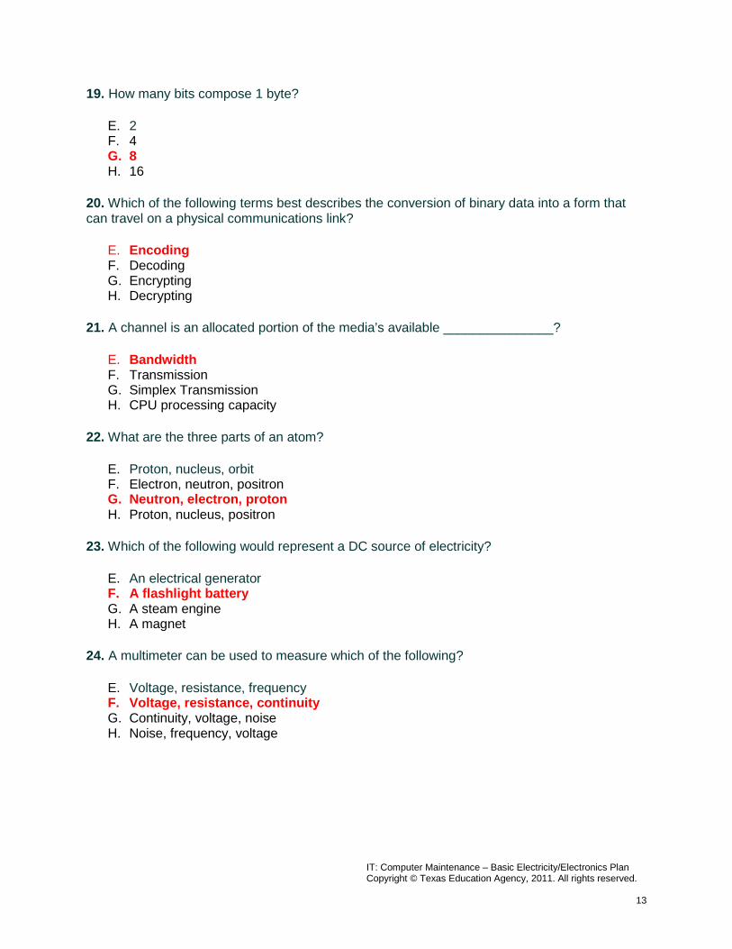
19. How many bits compose 1 byte?
E. 2 F. 4 G. 8 H. 16
20. Which of the following terms best describes the conversion of binary data into a form that can travel on a physical communications link?
E. Encoding F. Decoding G. Encrypting H. Decrypting
21. A channel is an allocated portion of the media’s available _______________?
E. Bandwidth F. Transmission G. Simplex Transmission H. CPU processing capacity
22. What are the three parts of an atom?
E. Proton, nucleus, orbit F. Electron, neutron, positron G. Neutron, electron, proton H. Proton, nucleus, positron
23. Which of the following would represent a DC source of electricity?
E. An electrical generator F. A flashlight battery G. A steam engine H. A magnet
24. A multimeter can be used to measure which of the following?
E. Voltage, resistance, frequency F. Voltage, resistance, continuity G. Continuity, voltage, noise H. Noise, frequency, voltage

IT: Computer Maintenance – Basic Electricity/Electronics Plan Copyright © Texas Education Agency, 2011. All rights reserved.
14
Computer Maintenance Basic Electricity/Electronics Lab 1: Using a Multimeter
Student Name: __________________________ Date: __________ Objective
Learn how to use a multimeter correctly.
Equipment
The following equipment is required for this exercise: • A digital multimeter for each student or team. • A manual for the multimeter. • A battery (i.e. 9v, 1.5v etc.), for each student or team to test.
NOTE: The multimeter is a sensitive piece of electronic test equipment. Be sure that you do not drop it or throw it around. Be careful not to accidentally nick or cut the red or black wire leads (probes). Since it is possible to check high voltages, extra care should be taken when doing so to avoid electrical shock.
Procedures
Perform the following steps to become familiar with the handling of the multimeter. 1st Step
Insert the red and black leads (probes) into the proper jacks on the meter. The black probe should go in the COM jack and the red probe should go in the + (plus or positive) jack.
2nd Step
Turn on the multimeter (click/turn the on button). What model of multimeter are you working with? _________________________________. What action must you take to turn the meter on? _______________________________________ ________________________________________________________________.
3rd Step
Switch or turn to different measurements (i.e. voltage, ohms, etc.). How many different switch positions do the multimeter have? _____. What are they?
________________________________________________________________.

IT: Computer Maintenance – Basic Electricity/Electronics Plan Copyright © Texas Education Agency, 2011. All rights reserved.
15
4th Step
Switch or turn the multimeter to the voltage measurement. What is the symbol for this? ________________________________________________________.
5th Step
Put the tip of the red (positive) lead on one end of a battery (+ side), and put the tip of the black (negative) lead on the other end of a battery. Is any number showing up on the multimeter? __________. If not make sure you switch to the correct type of measurement (Vol, voltage, or V). If the voltage is negative, reverse your leads.
NOTES:

IT: Computer Maintenance – Basic Electricity/Electronics Plan Copyright © Texas Education Agency, 2011. All rights reserved.
16
Computer Maintenance Basic Electricity/Electronics
Lab 2: Resistance Measurements
Student Name: __________________________ Date: __________ Objective
Demonstrate your ability to measure resistance and continuity with the multimeter.
Equipment
The following equipment is required for this exercise: • A digital multimeter for each student or team. • A 1,000 Ohm resistor for each student or team. • A 10,000 Ohm resistor for each student or team. • A pencil and paper for creating graphite paths on paper. • Cat 5 jack. • Small (0.2m or approximately 6 to 8 inches) section of Cat 5 UTP solid cable. • BNC terminated coaxial cable. • Unconnected DB9 to RJ-45 adapter. • Terminated Cat 5 UTP patch cable.
Procedures
Perform the following steps to become familiar with the handling of the multimeter. 1st Step
Move the rotary selector to the Omega symbol for Ohms (Ω) in order to measure resistance.
Press the button that has the Ohms symbol (Ω) on it to select between resistance measurements and continuity.
Resistance Measurements: The screen will show Ω (ohms), KΩ (kilohms = thousands of Ohms) or MΩ (megohms = millions of Ohms). Use the Range button to change the range of resistance to be measured based on what resistance you expect to get. If you expect low resistance (less than 10 ohms), select a low scale (like Ω). If you expect a high reading (over 10,000 ohms), select a high scale (like KΩ). If the resistance reading is over the range selected, the OL or Over Limit indicator will be displayed on the screen. The resistance setting is for measuring exact amounts of resistance.

IT: Computer Maintenance – Basic Electricity/Electronics Plan Copyright © Texas Education Agency, 2011. All rights reserved.
17
Continuity Measurements: The screen will show a diode symbol which is a small black triangle pointing to a vertical bar. A diode is an electronic device that either passes or blocks electrical current. You may see a small sound symbol next to it, which means that when there is good continuity (no resistance) the beep will sound. The continuity setting is used when you just want to know if there is a good path for electricity or not and don’t care about the exact amount of resistance.
2nd Step
Check the following resistances. Turn the multimeter off when finished or battery will drain. Item to Measure the resistance of:
Set Selector and Range Scale to:
Resistance Reading:
1000 Ω Resistor 10 kΩ Resistor Graphite marking from a pencil on a piece of paper
Cat 5 jack 0.2 m section of Cat 5 UTP solid cable
Touch red and black probe contacts together
Your own body (touch the tips of the probes with your fingers)
BNC terminated coaxial cable
Unconnected DB9 to RJ-45 adapter
Terminated Cat 5 UTP cable
NOTES:

IT: Computer Maintenance – Basic Electricity/Electronics Plan Copyright © Texas Education Agency, 2011. All rights reserved.
18
Computer Maintenance Basic Electricity/Electronics
Lab 3: Voltage Measurements
Student Name: __________________________ Date: __________ Objective
Demonstrate your ability to measure voltage SAFELY with the multimeter.
Equipment
The following is required voltage measurement items for this exercise: • A digital multimeter for each student or team. • An assortment of batteries: A cell, C cell, D Cell, 9 Volts, 6 V lantern. • Duplex wall outlet (typical 120v). • Power supply (for laptop, or other networking electrical device).
The following is optional voltage measurement items for this exercise:
• A lemon, with a galvanized nail stuck in one side, and a piece of uninsulated copper wire stuck in the opposite side.
• Solar cell with leads attached. • Home-made generator (wire wound around a pencil 50 times and a magnet).
Procedures
Perform the following steps to become familiar using the multimeter for voltage measurements:
1st Step
Move the rotary selector to the V symbol for voltage (black V) in order to be able to measure voltage. Press the button that has the VDC and VAC symbol to select between Direct Current (DC) or Alternating Current (AC) measurements. Direct Current Measurements: The screen will show a V (voltage) with a series of dots and a line over the top. There are several scales available depending on the voltage to be measured. They start from millivolts (abbreviated mV = 1,000/th of a volt) to voltages up to hundreds of volts. Use the Range button to change the range of DC voltage to be measured based on what voltage you expect to measure. Batteries (less than 15 volts) can typically be measured accurately with the VDC scale and 0.0 range. DC voltage measurements can be used to determine if batteries are good or if there is voltage coming out of an AC adapter (transformer or converter) which are very common and used with hubs, modems, laptops, printers

IT: Computer Maintenance – Basic Electricity/Electronics Plan Copyright © Texas Education Agency, 2011. All rights reserved.
19
and other peripherals. These adapters can take wall outlet AC voltage and step it down to lower AC voltages for the device attached or can convert the AC voltage to DC and step it down. Check the back of the adapter to see what the input (AC) and output voltages (AC or DC) should be. Alternating Current Measurements: The screen will show a V (voltage) with a tilde (~) after it. This represents alternating current. There are several scales available depending on the voltage to be measured. They start from millivolts (abbreviated mV = 1,000/th of a volt) to voltage up to hundreds of volts. Use the Range button to change the range of AC voltage to be measured based on what voltage you expect to measure. Voltage from power outlets (120v or greater) can typically be measured accurately with the VAC scale and 0.0 range. AC voltage measurements are useful in determining if there is adequate voltage coming from an AC outlet to power the equipment plugged in.
2nd Step
Check the following voltages. Turn the multimeter off when finished or battery will drain. Item to Measure the voltage of:
Set Selector and Range Scale to:
Voltage Reading:
Batteries: A cell (AA, AAA), C cell, D cell, 9 Volts, 6 V lantern
Duplex wall outlet (typical 120v)
Power supply (converts AC to lower AC or DC) for laptop, mobile phone, or other networking electrical device.
(Optional) A lemon, with a galvanized nail stuck in one side, and a piece of uninsulated copper wire stuck in the opposite side
(Optional) Solar cell with leads attached
(Optional) Home-made generator (wire wound around a pencil 50 times and a magnet)
NOTES:

IT: Computer Maintenance – Basic Electricity/Electronics Plan Copyright © Texas Education Agency, 2011. All rights reserved.
20
Computer Maintenance Basic Electricity/Electronics
Lab 4: Series Circuits Student Name: __________________________ Date: __________ Objective
Build series circuits and explore their basic properties.
Equipment
The following is required equipment for this exercise: • A digital multimeter for each student or team. • A light switch for each student or team. • Wire cutter/stripper for each student or team. • Copper Wire. • 2 light bulbs (6v) with bulb bases for each student or team. • 6-Volt lantern battery for each student or team.
Procedures
Perform the following steps to explore the basic properties of series circuits: 1st Step
Measure the resistances of all devices and components except the battery. Measure the voltage of the battery. All resistances should be less than 1 Ω (Ohm), except the light bulbs. All the devices except the battery should register continuity (with the tone) indicating a short circuit, or a conducting path. Check the following resistance. Turn the multimeter off when finished or it will drain the battery.
Item to Measure the Resistance of:
Set Selector and Range Scale to:
Resistance Reading:
Pieces of wire to connect components
Light switch Light bulbs

IT: Computer Maintenance – Basic Electricity/Electronics Plan Copyright © Texas Education Agency, 2011. All rights reserved.
21
2nd Step
Measure the voltage of the battery, unloaded (with nothing attached to it). Item to Measure the voltage of:
Set Selector and Range Scale to:
Voltage Reading:
Lantern Battery: (6 V) with no load
3rd Step
Build a series circuit, one device at a time (use 1 battery, 1 switch, 1 bulb and connecting wires).
Connect the battery positive lead to one end of wire and connect the negative lead to the other wire. If the switch is turned on, the bulb should light. Disconnect one thing and see that the circuit is broken. Did the bulb go out? ________________.
4th Step
Measure the battery voltage while the circuit is running. The switch should be turned on and the light bulb should be lit. What was the voltage of the battery with the light bulb on? ________________________.
5th Step
Add the second bulb in series and measure the battery voltage again. What was the voltage of the battery with the light bulb on? _______________.
NOTES: