MODEL G0528 ROUTER TABLE - cdn0.grizzly.comcdn0.grizzly.com/manuals/g0528_m.pdf · The Model G0528...
36
COPYRIGHT © SEPTEMBER, 2003 BY GRIZZLY INDUSTRIAL, INC. REVISED MARCH, 2017 (MN) WARNING: NO PORTION OF THIS MANUAL MAY BE REPRODUCED IN ANY SHAPE OR FORM WITHOUT THE WRITTEN APPROVAL OF GRIZZLY INDUSTRIAL, INC. #CR11780 PRINTED IN TAIWAN MODEL G0528 ROUTER TABLE OWNER'S MANUAL (For models manufactured since 03/17)
Transcript of MODEL G0528 ROUTER TABLE - cdn0.grizzly.comcdn0.grizzly.com/manuals/g0528_m.pdf · The Model G0528...

COPYRIGHT © SEPTEMBER, 2003 BY GRIZZLY INDUSTRIAL, INC. REVISED MARCH, 2017 (MN)WARNING: NO PORTION OF THIS MANUAL MAY BE REPRODUCED IN ANY SHAPE
OR FORM WITHOUT THE WRITTEN APPROVAL OF GRIZZLY INDUSTRIAL, INC.#CR11780 PRINTED IN TAIWAN
MODEL G0528ROUTER TABLE
OWNER'S MANUAL(For models manufactured since 03/17)

This manual provides critical safety instructions on the proper setup, operation, maintenance, and service of this machine/tool. Save this document, refer to it often, and use it to instruct other operators.
Failure to read, understand and follow the instructions in this manual may result in fire or serious personal injury—including amputation, electrocution, or death.
The owner of this machine/tool is solely responsible for its safe use. This responsibility includes but is not limited to proper installation in a safe environment, personnel training and usage authorization, proper inspection and maintenance, manual availability and compre-hension, application of safety devices, cutting/sanding/grinding tool integrity, and the usage of personal protective equipment.
The manufacturer will not be held liable for injury or property damage from negligence, improper training, machine modifications or misuse.
Some dust created by power sanding, sawing, grinding, drilling, and other construction activities contains chemicals known to the State of California to cause cancer, birth defects or other reproductive harm. Some examples of these chemicals are:
• Lead from lead-based paints.• Crystalline silica from bricks, cement and other masonry products.• Arsenic and chromium from chemically-treated lumber.
Your risk from these exposures varies, depending on how often you do this type of work. To reduce your exposure to these chemicals: Work in a well ventilated area, and work with approved safety equip-ment, such as those dust masks that are specially designed to filter out microscopic particles.

Table of ContentsINTRODUCTION ............................................................................................................................... 2
Manual Accuracy ........................................................................................................................ 2Contact Info ................................................................................................................................ 2Machine Description ................................................................................................................... 2Identification ............................................................................................................................... 3Machine Data Sheet ................................................................................................................... 4
SECTION 1: SAFETY ....................................................................................................................... 5Safety Instructions for Machinery ............................................................................................... 5Additional Safety Instructions for Sliding Router Tables ............................................................ 7
SECTION 2: CIRCUIT REQUIREMENTS ........................................................................................ 8110V Operation .......................................................................................................................... 8
SECTION 3: SETUP ......................................................................................................................... 9Needed for Setup ....................................................................................................................... 9Unpacking .................................................................................................................................. 9Inventory ................................................................................................................................... 10Hardware Recognition Chart .................................................................................................... 11Cleanup .................................................................................................................................... 12Site Considerations .................................................................................................................. 13Assembly .................................................................................................................................. 14Miter ......................................................................................................................................... 17Router ....................................................................................................................................... 18Test Run ................................................................................................................................... 19
SECTION 4: OPERATIONS ........................................................................................................... 20Operation Overview.................................................................................................................. 20Workpiece Inspection ............................................................................................................... 21Routing ..................................................................................................................................... 21
SECTION 5: ACCESSORIES ......................................................................................................... 24
SECTION 6: MAINTENANCE......................................................................................................... 25Schedule .................................................................................................................................. 25Cleaning ................................................................................................................................... 25Unpainted Cast Iron ................................................................................................................. 25
SECTION 7: WIRING ...................................................................................................................... 26Wiring Safety Instructions ........................................................................................................ 26Wiring Diagram......................................................................................................................... 27
SECTION 8: PARTS ....................................................................................................................... 28Main Breakdown....................................................................................................................... 28Parts List .................................................................................................................................. 29Labels and Parts List................................................................................................................ 30
WARRANTY AND RETURNS ........................................................................................................ 33

-2- Model G0528 (Mfd. 3/17+)
INTRODUCTION
The Model G0528 sliding router table allows the woodworker to mount most routers to the table underside with the spindle and cutter protruding upward from the table. Similar to a shaper, the workpiece is slid along an adjustable fence and into the cutter. Unlike a shaper, the Model G0528 has a sliding table feature where the table moves with the workpiece into the cutter. This design improves workpiece control, especially when rout-ing the end grain of a workpiece. For support on both sides of the workpiece, the sliding router table is equipped with a split-rail type fence. For easy ON/OFF control, the table has been fitted with a router power switch.
Machine Description
We stand behind our machines! If you have ques-tions or need help, contact us with the information below. Before contacting, make sure you get the serial number and manufacture date from the machine ID label. This will help us help you faster.
Grizzly Technical Support1815 W. Battlefield
Springfield, MO 65807Phone: (570) 546-9663
Email: [email protected]
We want your feedback on this manual. What did you like about it? Where could it be improved? Please take a few minutes to give us feedback.
Grizzly Documentation ManagerP.O. Box 2069
Bellingham, WA 98227-2069Email: [email protected]
Contact Info
We are proud to provide a high-quality owner’s manual with your new machine!
We made every effort to be exact with the instruc-tions, specifications, drawings, and photographs in this manual. Sometimes we make mistakes, but our policy of continuous improvement also means that sometimes the machine you receive is slightly different than shown in the manual.
If you find this to be the case, and the difference between the manual and machine leaves you confused or unsure about something, check our website for an updated version. We post current manuals and manual updates for free on our web-site at www.grizzly.com.
Alternatively, you can call our Technical Support for help. Before calling, make sure you write down the Manufacture Date and Serial Number from the machine ID label (see below). This information is required for us to provide proper tech support, and it helps us determine if updated documenta-tion is available for your machine.
Manufacture Date
Serial Number
Manual Accuracy

Model G0528 (Mfd. 3/17+) -3-
Set up and operation instructions will be easier to understand if you become familiar with the location and names of the machine features shown in Figure 1.
Figure 1. Machine features.
Identification
Outfeed Fence
Sliding Table
Power Switch
Table Tilt Brackets
Miter Gauge
Main Table
Infeed FenceDust PortWorkpiece Hold-Downs

-4- Model G0528 (Mfd. 3/17+)
Design Type ..................................................................................................... Floor Model
Overall Dimensions: Main Table ................................................................................31" W x 10" D x 13⁄4" T Sliding Table .......................................................................................... 31" W x 12" D Total Table Surface ................................................................................ 31" W x 22" D Overall Height ...................................................................................................... 42" H Height From Table To Floor ................................................................................. 34" H Overall Width ........................................................................................................ 40"W Overall Length ...................................................................................................... 30" D Shipping Weight ............................................................................................... 132 lbs. Net Machine Weight ......................................................................................... 125 lbs. Box Size ....................................................................................351⁄2" W x 26" D x 8" H Footprint ................................................................................................. 40" W x 30" DCapacities: Suitable Routers For Mounting ................................................................. 3⁄4 HP - 5 HP Table Counterbore ..................................................................................................31⁄2" Table Insert Opening Sizes .........................................................................11⁄8" & 25⁄16" Fence Size ..................................................................................3" x 12" (Each Piece) Maximum Fence Working Surface ....................................................................3" x 36" Dust Port .................................................................................................................21⁄2"Construction: Main Table ....................................................................... Precision-Ground Cast Iron Sliding Table ................................................................................................. Aluminum Fence Assembly ............................................................................... Aluminum & Steel Stand ...........................................................................................Powder-Coated Steel Miter Body ..................................................................................................... AluminumFeatures: ................................................................................................ Workpiece Hold-Downs ..................................................................................................Clamping Miter Gauge ........................................................................................ Toggle Switch W/Safety Key ................................. Dual Power Outlets For Convenient Router/Accessory Plug-Ins ......................................................................45˚ Table Tilt For Easy Router Mounting ................................................................................................................. Sliding Table
Specifications, while deemed accurate, are not guaranteed.8/2003
Customer Service #: (570) 546-9663 • To Order Call: (800) 523-4777 • Fax #: (800) 438-5901
model g0528 RoUTeR TABle
mACHINe dATAsHeeT
Machine Data Sheet

Model G0528 (Mfd. 3/17+) -5-
ELECTRICAL EQUIPMENT INJURY RISKS. You can be shocked, burned, or killed by touching live electrical components or improperly grounded machinery. To reduce this risk, only allow qualified service personnel to do electrical installation or repair work, and always disconnect power before accessing or exposing electrical equipment.
DISCONNECT POWER FIRST. Always discon-nect machine from power supply BEFORE making adjustments, changing tooling, or servicing machine. This prevents an injury risk from unintended startup or contact with live electrical components.
EYE PROTECTION. Always wear ANSI-approved safety glasses or a face shield when operating or observing machinery to reduce the risk of eye injury or blindness from flying particles. Everyday eyeglasses are NOT approved safety glasses.
OWNER’S MANUAL. Read and understand this owner’s manual BEFORE using machine.
TRAINED OPERATORS ONLY. Untrained oper-ators have a higher risk of being hurt or killed. Only allow trained/supervised people to use this machine. When machine is not being used, dis-connect power, remove switch keys, or lock-out machine to prevent unauthorized use—especially around children. Make workshop kid proof!
DANGEROUS ENVIRONMENTS. Do not use machinery in areas that are wet, cluttered, or have poor lighting. Operating machinery in these areas greatly increases the risk of accidents and injury.
MENTAL ALERTNESS REQUIRED. Full mental alertness is required for safe operation of machin-ery. Never operate under the influence of drugs or alcohol, when tired, or when distracted.
For Your Own Safety, Read Instruction Manual Before Operating This Machine
The purpose of safety symbols is to attract your attention to possible hazardous conditions. This manual uses a series of symbols and signal words intended to convey the level of impor-tance of the safety messages. The progression of symbols is described below. Remember that safety messages by themselves do not eliminate danger and are not a substitute for proper accident prevention measures. Always use common sense and good judgment.
Indicates a potentially hazardous situation which, if not avoided, MAY result in minor or moderate injury. It may also be used to alert against unsafe practices.
Indicates a potentially hazardous situation which, if not avoided, COULD result in death or serious injury.
Indicates an imminently hazardous situation which, if not avoided, WILL result in death or serious injury.
This symbol is used to alert the user to useful information about proper operation of the machine.NOTICE
Safety Instructions for Machinery
SECTION 1: SAFETY

-6- Model G0528 (Mfd. 3/17+)
WEARING PROPER APPAREL. Do not wear clothing, apparel or jewelry that can become entangled in moving parts. Always tie back or cover long hair. Wear non-slip footwear to avoid accidental slips, which could cause loss of work-piece control. Wear hard hat as needed.
HAZARDOUS DUST. Dust created while using tools may cause cancer, birth defects, or long-term respiratory damage. Be aware of dust haz-ards associated with each workpiece material, always wear a NIOSH-approved respirator, and connect tool to an appropriate dust collection device to reduce your risk.
HEARING PROTECTION. Always wear hear-ing protection when operating or observing loud machinery. Extended exposure to this noise without hearing protection can cause permanent hearing loss.
REMOVE ADJUSTING TOOLS. Never leave adjustment tools, chuck keys, wrenches, etc. in or on tool—especially near moving parts. Verify removal before starting!
INTENDED USAGE. Only use tool for its intended purpose. Never modify or alter tool for a purpose not intended by the manufacturer or serious injury or death may result!
AWKWARD POSITIONS. Keep proper footing and balance at all times when operating tool. Do not overreach! Avoid awkward hand positions that make tool control difficult or increase the risk of accidental injury.
SAFE HANDLING. Firmly grip tool. To avoid accidental firing, do not keep finger on switch or trigger while carrying.
SECURING WORKPIECE. When required, use clamps or vises to secure workpiece. A secured workpiece protects hands and frees both of them to operate the tool.
GUARDS & COVERS. Guards and covers reduce accidental contact with moving parts or flying debris. Make sure they are properly installed, undamaged, and working correctly.
CHILDREN & BYSTANDERS. Keep children and bystanders at a safe distance from the work area.Stop using machine if they become a distraction.
FORCING TOOLS. Use the right tool for the job, and do not force it. It will do the job safer and bet-ter at the rate for which it was designed.
USE RECOMMENDED ACCESSORIES. Consult this owner’s manual or the manufacturer for rec-ommended accessories. Using improper acces-sories will increase the risk of serious injury.
MAINTAIN WITH CARE. Keep cutting tool edges sharp and clean. Follow all maintenance instruc-tions and lubrication schedules to keep tool in good working condition. A tool that is improperly maintained could malfunction, leading to serious personal injury or death. Only have tool serviced by qualified service-personnel using matching replacement parts.
CHECK DAMAGED PARTS. Regularly inspect tool for any condition that may affect safe opera-tion. Immediately repair or replace damaged or mis-adjusted parts before operating tool.
MAINTAIN POWER CORDS. When disconnect-ing cord-connected tools from power, grab and pull the plug—NOT the cord. Carrying or pulling the cord may damage wires inside. Do not handle cord/plug with wet hands. Avoid cord damage by keeping it away from heated surfaces, high traf-fic areas, harsh chemicals, sharp edges, moving parts, and wet/damp locations. Damaged cords increase risk of electrocution.
UNATTENDED OPERATION. Never leave tool running while unattended. Turn tool off and ensure all moving parts completely stop before walking away.
EXPERIENCING DIFFICULTIES. If at any time you experience difficulties performing the intend-ed operation, stop using the machine! Contact our Technical Support at (570) 546-9663.

Model G0528 (Mfd. 3/17+) -7-
Additional Safety Instructions for Sliding Router Tables
No list of safety guidelines can be complete. Every shop environment is different. Always consider safety first, as it applies to your individual working conditions. Use this and other machinery with caution and respect. Failure to do so could result in serious per-sonal injury, damage to equipment, or poor work results.
Like all machines there is danger associ-ated with the Model G0528. Accidents are frequently caused by lack of familiarity or failure to pay attention. Use this machine with respect and caution to lessen the pos-sibility of operator injury. If normal safety precautions are overlooked or ignored, seri-ous personal injury may occur.
AVOIDING AMPUTATION. Never place hands directly over or in front of the cutter. As one hand approaches the cutter, move it away. Always keep hand at least 6” away from the cutter while operat-ing.
SECURING LEVERS AND KNOBS. Never oper-ate the router table without first making sure that all lock levers and knobs are tight, and that all fence hardware and guide rails are secure. Otherwise, the workpiece can slip out of alignment during cut-ting and be kicked back causing injury.
PREVENTING WORKPIECE DRAW-IN or KICKBACK. Always feed the workpiece against the rotation of the cutter. Never force materials through the machine. Let the cutter do the work. Excessive force is likely to result in poor cutting results and will cause dangerous kickback condi-tions.
APPROPRIATE WORKPIECES. The danger of kickback and injury is increased when the work-piece has knots, holes, or foreign objects in it. Warped stock should be run through a jointer before you run it through the router table.
BLIND CUTTING. Keep the cutter on the under-side of the workpiece when making blind cuts, which decreases risk of accidental contact with the cutter.
TESTING ROTATION. With the machine discon-nected from power, rotate the spindle to test any new setup to ensure proper cutter clearance before starting the machine.
CUTTING DEPTH. Never remove too much mate-rial in one pass. Several light cuts produce a cleaner finish and help prevent kickback.
CUTTING SUPPORT. NEVER cut a workpiece without using a fence, jig, or miter. Otherwise, the workpiece can be grabbed by the cutter causing severe injury. Whenever possible, use a fixture, jig, or clamping device to hold or guide the workpiece.
WORKPIECE SIZING. NEVER use a workpiece shorter than six inches without special fixtures or jigs. Otherwise, the workpiece can become trapped between the fence and cutter causing injury.
CUTTER HEIGHT. Keep any unused portion of the cutter below the table surface, or a workpiece can be grabbed by the cutter causing severe injury.
USING SAFETY GUARDS. To prevent amputation or other injuries, NEVER remove any guards or covers when machine is operating. Fabricate addi-tional guards or jigs for special circumstances. Use an overhead guard when the fence is removed.

-8- Model G0528 (Mfd. 3/17+)
Figure 2. Typical 5-15 plug and receptacle.
Grounding Prong
Neutral Hot
5-15 PLUG
GROUNDED5-15 RECEPTACLE
110V Operation
Full Load Amperage DrawThis router table is equipped with a 5-15, 110V, 15 amp receptacle, power cord, and power switch. When selecting a router to use with this router table, do not use routers that draw more than 15 amps under a full load.
Power Supply Circuit RequirementsThe power supply circuit for the router table MUST be grounded and rated for the amperage given below. Never replace a circuit breaker on an existing circuit with one of higher amperage without consulting a qualified electrician to ensure compliance with wiring codes. If you are unsure about the wiring codes in your area or you plan to connect your machine to a shared cir-cuit, consult a qualified electrician.
Minimum Circuit Size ............................. 15 Amps
This machine MUST have a ground prong in the plug to help ensure that it is grounded. DO NOT remove ground prong from plug to fit into a two-pronged outlet! If the plug will not fit the outlet, have the proper outlet installed by a qualified electrician.
Extension CordsWe do not recommend using extension cords, but if you find it absolutely necessary:
• Use at least a 14 gauge cord that does not exceed 50 feet in length!
• The extension cord must have a ground wire and plug pin.
• A qualified electrician MUST size cords over 50 feet long to prevent motor damage.
SECTION 2: CIRCUIT REQUIREMENTS
Serious personal injury could occur if you connect the machine to power before com-pleting the setup process. DO NOT connect the machine to the power until instructed later in this manual.
Electrocution or fire could result if machine is not grounded and installed in compliance with electrical codes. Compliance MUST be verified by a qualified electrician!
Power Connection DeviceThis machine comes with a plug, similar to Figure 2, to connect the machine to power.

Model G0528 (Mfd. 3/17+) -9-
Wear safety glasses dur-ing the entire setup pro-cess!
SECTION 3: SETUP
The following are needed to complete the setup process, but are not included with your machine.
Description Qty• Safety Glasses ........................................... 1• Cleaner/Degreaser (Page 12) .... As Needed• Disposable Shop Rags ............... As Needed• Assistant ..................................................... 1• Straightedge 4' ........................................... 1• Screwdriver Phillips #2 ............................... 1• Screwdriver Flat Head #2 ........................... 1• Dust Collection System .............................. 1• Dust Hose 21⁄2" Inside Diameter ................. 1• Hose Clamps 21⁄2" inside Diameter ............ 2• Wrench 10mm ............................................ 1• Wrench 12mm ............................................ 1• Wrench 14mm ............................................ 1• Wrench 19mm ............................................ 1
Needed for Setup
Your machine was carefully packaged for safe transportation. Remove the packaging materials from around your machine and inspect it. If you discover the machine is damaged, please imme-diately call Customer Service at (570) 546-9663 for advice.
Save the containers and all packing materials for possible inspection by the carrier or its agent. Otherwise, filing a freight claim can be difficult.
When you are completely satisfied with the condi-tion of your shipment, inventory the contents.
Unpacking
This machine and its com-ponents are very heavy. Get lifting help or use power lifting equipment such as a forklift to move heavy items.
To reduce your risk of serious injury, read this entire manual BEFORE using machine.

-10- Model G0528 (Mfd. 3/17+)
Please inventory your shipment with this list. If any nonproprietary parts are missing (e.g. a nut or a washer), we will gladly replace them; or for the sake of expediency, replacements can be obtained at your local hardware store.
Box 1: (Figure 3) QtyNote: Table and Shelf not Shown.A. Left Fence .................................................. 1B. Right Fence ................................................ 1C. Dust Hood .................................................. 1D. Power Cord ................................................ 1E. Switch ......................................................... 1F. Switch Box .................................................. 1G. Workpiece Hold-Downs .............................. 2H. Miter Plate .................................................. 1I. Miter Fence ................................................ 1J. Router Clamps ........................................... 4K. Table Insert 29MM ..................................... 1L. Table Insert 60MM ..................................... 1M. Fence Lock Handles .................................. 2N. Hardware Bag
— Rubber Stops (Flange Brackets)............. 2— Phillips Screws 1⁄4"-20 x 11⁄2" (Lock Arm) 2— Flat Washers 1⁄4" (Lock Arm) ................... 4— Hex Nuts 1⁄4"-20 (Lock Arm) .................... 4— Hex Bolts 5⁄16"-18 x 1" (Table Pivot) ......... 2
— Lock Nuts 5⁄16"-18 (Table Pivot) ............... 2— Flat Washers 5⁄16" (Table Pivot) ............... 4— Hex Nuts 5⁄16"-18 (Table/Stand) ............... 4— Flat Washers 5⁄16" (Table/Stand) ............. 8— Cap Screws 5⁄16"-18 x 11⁄2" (Stops) .......... 2— Spacers ................................................... 2
O. Hardware Bag— Carriage Bolts 5⁄16"-18 x 1⁄2" (Legs) ........ 32— Flat Washers 5⁄16" (Legs) ....................... 32— Lock Washers 5⁄16" (Legs) ..................... 32— Hex Nuts 5⁄16"-18 (Legs)......................... 32— Rubber Feet (Legs) ................................. 4— Hex Nuts 5⁄16"-18 (Legs)........................... 4— Flat Washers 5⁄16" (Legs) ......................... 4— Phillips Screws 1⁄4"-20 x 1 (Stand Pad) ... 4— Flat Washers 1⁄4" (Stand Pad) ................. 4— Hex Nuts 1⁄4"-20 (Stand Pad) .................. 4— Phillips Screws #10-24 x 3⁄4 (Switch) ....... 3— External Tooth Washers #10 (Switch) ..... 3— Hex Nuts #10-24 (Switch) ....................... 3
P. Diagonal Supports ...................................... 2Q. Stand Legs ................................................. 4R. Front Support ............................................. 1S. Strain Relief ................................................ 1T. Side Supports ............................................. 2U. Right and Left Flange Brackets ............. 1EA
Inventory
Figure 3. G0528 Inventory.
A
B
C
E
D
F
G
P
Q
R
H
I
J
K L
M
NO
S
T
U

Model G0528 (Mfd. 3/17+) -11-
5mm
Hardware Recognition Chart

-12- Model G0528 (Mfd. 3/17+)
The unpainted surfaces of your machine are coated with a heavy-duty rust preventative that prevents corrosion during shipment and storage.
This rust preventative has been your machine's close ally and guardian since it left the factory. If your machine arrived to you free of rust, then be thankful that the rust preventative protected it during its journey and try to stay thankful as you clean it off, because it can be challenging to remove if you are unprepared and impatient.
Plan on spending some time cleaning your machine. The time you spend doing this will reward you with smooth sliding parts and a better appreciation for the proper care of your machine's unpainted surfaces.
Although there are many ways to successfully remove the rust preventative, these instructions walk you through what works well for us.
Before cleaning, gather the following:• Disposable Rags• Cleaner/degreaser (Figure 4)• Safety glasses & disposable gloves
Cleanup
H9692—Orange Power Cleaner & DegreaserOne of the best cleaners we've found for quickly and easily removing rust preventative.
Figure 4. Model H9692 Industrial Orange Power Cleaner/Degreaser (99.9% biodegradable).
Basic steps for removing Rust preventative:
1. Put on safety glasses and disposable gloves.
2. Coat all surfaces that have rust preventa-tive with a liberal amount of your cleaner/degreaser and let them soak for few min-utes.
3. Wipe off the surfaces. If your cleaner/degreaser is effective, the rust preventative will wipe off easily.
Note: To clean off thick coats of rust preven-tative on flat surfaces, such as tables, use a PLASTIC paint scraper to scrape off the majority of the coating before wiping it off with your rag. (Do not use a metal scraper or you may scratch your machine).
4. Repeat Steps 2–3 as necessary until clean, then coat all unpainted surfaces with a quality metal protectant to prevent rust.
Gasoline and petroleum products have low flash points and can explode or cause fire if used to clean machinery. Avoid using these products to clean machinery.
Many cleaning solvents are toxic if inhaled. Minimize your risk by only using these products in a well ventilated area.
NOTICEAvoid chlorine-based solvents, such as acetone or brake parts cleaner that may damage painted surfaces. Always follow the manufacturer’s instructions when using any type of cleaning product.
Note: In a pinch, automotive degreasers, mineral spirits or WD•40 can be used to remove rust pre-ventative. Before using these products, though, test them on an unnoticeable area of your paint to make sure they will not damage it.

Model G0528 (Mfd. 3/17+) -13-
Site Considerations
Figure 5. Minimum working clearances.
Weight LoadRefer to the Machine Data Sheet for the weight of your machine. Make sure that the surface upon which the machine is placed will bear the weight of the machine, additional equipment that may be installed on the machine, and the heaviest work-piece that will be used. Additionally, consider the weight of the operator and any dynamic loading that may occur when operating the machine.
Space AllocationConsider the largest size of workpiece that will be processed through this machine and provide enough space around the machine for adequate operator material handling or the installation of auxiliary equipment. With permanent installations, leave enough space around the machine to open or remove doors/covers as required by the main-tenance and service described in this manual. See below for required space allocation.
Physical EnvironmentThe physical environment where the machine is operated is important for safe operation and lon-gevity of machine components. For best results, operate this machine in a dry environment that is free from excessive moisture, hazardous chemi-cals, airborne abrasives, or extreme conditions. Extreme conditions for this type of machinery are generally those where the ambient temperature range exceeds 41°–104°F; the relative humidity range exceeds 20%–95% (non-condensing); or the environment is subject to vibration, shocks, or bumps.
Electrical InstallationPlace this machine near an existing power source. Make sure all power cords are protected from traffic, material handling, moisture, chemicals, or other hazards. Make sure to leave enough space around machine to disconnect power supply or apply a lockout/tagout device, if required.
LightingLighting around the machine must be adequate enough that operations can be performed safely. Shadows, glare, or strobe effects that may distract or impede the operator must be eliminated.
Children or untrained people may be seriously injured by this machine. Only install in an access restricted location.
31"
40"
Dust Collection Hose Port

-14- Model G0528 (Mfd. 3/17+)
Assembly
To assemble the machine:
1. Secure the rubber feet to the stand legs with the four 1⁄4"-20 x 1" Phillips screws, 1⁄4"-20 hex nuts, and 1⁄4" flat washers (Figure 6).
4. Using two 5⁄16"-18 x 11⁄2" cap screws, 5⁄16" flat washers, and 5⁄16"-18 hex nuts, install the rub-ber stops at the end of the flange brackets (Figure 8).
Figure 8. Table support assembly.
Side Support
Flange Bracket
5. At the pivot bolt locations (Figure 7), attach the flange bracket to the table with two 5⁄16"-18 x 1" hex bolts, six 5⁄16" flat washers, and two 5⁄16"-18 lock nuts.
Marked "L" Marked "R"
Front Support
Figure 6. Rubber feet installation.
Flange Bracket
Front Support
Side Support
Pivot Hole
Figure 7. Table support and bracket order.
2. Arrange the front support, side supports, and the "L" and "R" flange brackets in the order shown in Figures 7–8. Be sure that the pivot holes in the flange brackets are located at the orientation shown in Figure 7.
3. Fasten the brackets together at both ends of the front support (Figure 8) with one 5⁄16"-18 x 1" hex bolt, two 5⁄16" flat washers, and one 5⁄16"-18 hex nut.
Figure 9. Table pivot installation.
Pivot Bolt
Table
Rubber Stop

Model G0528 (Mfd. 3/17+) -15-
Note: For the next few steps, do not com-pletely tighten the fasteners until instructed.
6. Position the legs on the outside of the side supports, and secure the legs to the supports with (12) 5⁄16"-18 x 1⁄2" carriage bolts, 5⁄16" flat washers, 5⁄16" lock washers, and 5⁄16"-18 hex nuts.
Note: In the normal upright view if looking at the machine from the front, the leg with the switch cut-out should be on the right hand side to allow for switch mounting clearance.
7. Secure the shelf to the stand legs with (16) 5⁄16"-18 x 1⁄2" carriage bolts, 5⁄16" flat washers, 5⁄16" lock washers, and 5⁄16"-18 hex nuts.
8. Secure the diagonal supports (Figure 10) to the legs and the shelf with (4) 5⁄16"-18 x 1⁄2" carriage bolts, 5⁄16" flat washers, 5⁄16" lock washers, and 5⁄16"-18 hex nuts.
9. In the order shown in Figure 11, slide a washer onto each screw, and insert the screws through the holes in each brace, then thread the screws through the spacers.
Note: Allow just enough of a gap between the washers and spacers for the table braces to slide freely.
Figure 11. Assembling the table braces.
SPECIFICATIONS
FA
ILUR
E T
O F
OLLO
W T
HE
SE
WA
RN
ING
S W
ILL RE
SU
LT IN
SE
RIO
US
PE
RS
ON
AL IN
JUR
Y:
1. RE
AD
AN
D U
ND
ER
STA
ND
TH
E R
OU
TE
R A
ND
RO
UTE
R
TA
BLE
MA
NU
AL B
EFO
RE
STA
RTIN
G T
HE
MA
CH
INE
.
2. ALW
AY
S W
EA
R E
YE
PR
OTE
CTIO
N A
ND
A R
ES
PIR
ATO
R.
3. PLU
G P
OW
ER
CO
RD
INTO
GR
OU
ND
ED
OU
TLE
T O
NLY
.
4. ALW
AY
S K
EE
P H
AN
DS
OU
T O
F T
HE
CU
TTE
R P
ATH
.
5. KE
EP
ALL G
UA
RD
S IN
PLA
CE
AT A
LL TIM
ES
.
6. DO
NO
T W
EA
R LO
OS
E C
LOTH
ING
, GLO
VE
S O
R JE
WE
LRY
.
SE
CU
RE
LON
G H
AIR
AN
D B
UTTO
N A
LL LON
G S
LEE
VE
SH
IRTS
.
7. DIS
CO
NN
EC
T P
OW
ER
PR
IOR
TO
SE
RV
ICIN
G, C
HA
NG
ING
CU
TTE
RS
OR
AD
JUS
TIN
G F
EN
CE
AN
D M
ITE
R G
AU
GE
.
8. DO
NO
T E
XP
OS
E T
O R
AIN
OR
DA
MP
NE
SS
.
9. DO
NO
T O
PE
RA
TE
UN
DE
R T
HE
INFLU
EN
CE
OF D
RU
GS
OR
ALC
OH
OL.
10. MA
KE
SU
RE
MA
CH
INE
IS P
RO
PE
RLY
AD
JUS
TE
D A
ND
SE
T
UP
CO
RR
EC
TLY
BE
FO
RE
STA
RTIN
G M
OTO
R.
11. BE
FO
RE
STA
RTIN
G M
AC
HIN
E, M
AK
E C
ER
TA
IN IT
RE
STS
SE
CU
RE
LY O
N F
LAT, LE
VE
L GR
OU
ND
.
12. KN
OW
HO
W T
O A
VO
ID R
ISK
OF K
ICK
BA
CK
.
13. DO
NO
T R
EM
OV
E JA
MM
ED
OR
CU
T-O
FF W
OR
KP
IEC
E
WH
ILE C
UTTE
R IS
TU
RN
ING
.
14. BE
FOR
E S
TAR
TING
MA
CH
INE
, MA
KE
SU
RE
CU
TTER
IS
INS
TALLE
D C
OR
RE
CTLY
AN
D P
RO
PE
RLY
TIGH
TEN
ED
.
15. NE
VE
R M
AK
E FR
EE
-HA
ND
CU
TS. A
LWA
YS
US
E TH
E
FEN
CE
OR
MITE
R.
16. BE
FOR
E S
TAR
TING
MA
CH
INE
, ALW
AY
S C
HE
CK
FEE
D
DIR
EC
TION
.
17. MA
KE
SU
RE
CU
TTER
HA
S C
OM
E TO
A C
OM
PLE
TE S
TOP
PR
IOR
TO M
AK
ING
AN
Y A
DJU
STM
EN
TS.
18. NE
VE
R A
TTEM
PT TO
RE
MO
VE
TOO
MU
CH
MA
TER
IAL IN
ON
E P
AS
S.
G0528
SLIDING ROUTER TABLE
UNIVERSAL ROUTER MOUNTING SYSTEM
TABLE INSERT DIAMETERS: 1-1/8", 2-5/16"
TABLE COUNTERBORE: 3-1/2"
DUST PORT: 2-1/2"
STAND: POWDER-COATED STEEL
WEIGHT: 125 LBS.
Date
Serial Number
Manufactured for Grizzly in Taiwan
READ AND UNDERSTAND THE
ROUTER AND ROUTER TABLE
OPERATOR'S MANUAL BEFORE
USING THIS MACHINE. FAILURE
TO FOLLOW OPERATING
INSTRUCTIONS WILL RESULT IN
DEATH OR SERIOUS PERSONAL
INJURY.
Hands and fingers can become seriously injured if they are pinched between the stand edge and the table. DO NOT place hands or fingers near the stand edge while the table is in the raised position.
Figure 10. Table diagonal support positions.
Shelf10. Secure with the washers and hex nuts.
11. Secure the left and right fence assemblies to the table with the fence lock handles in the holes located closest to the edge of the cast iron table.
12. Secure the dust hood to the top of each fence assembly with the pre-installed lock nuts (Figure 12).
Figure 12. Installed fence and dust hood.
FenceHousing
Lock Nuts
Dust Hood
Alignment
-16- Model G0528 (Mfd. 3/17+)
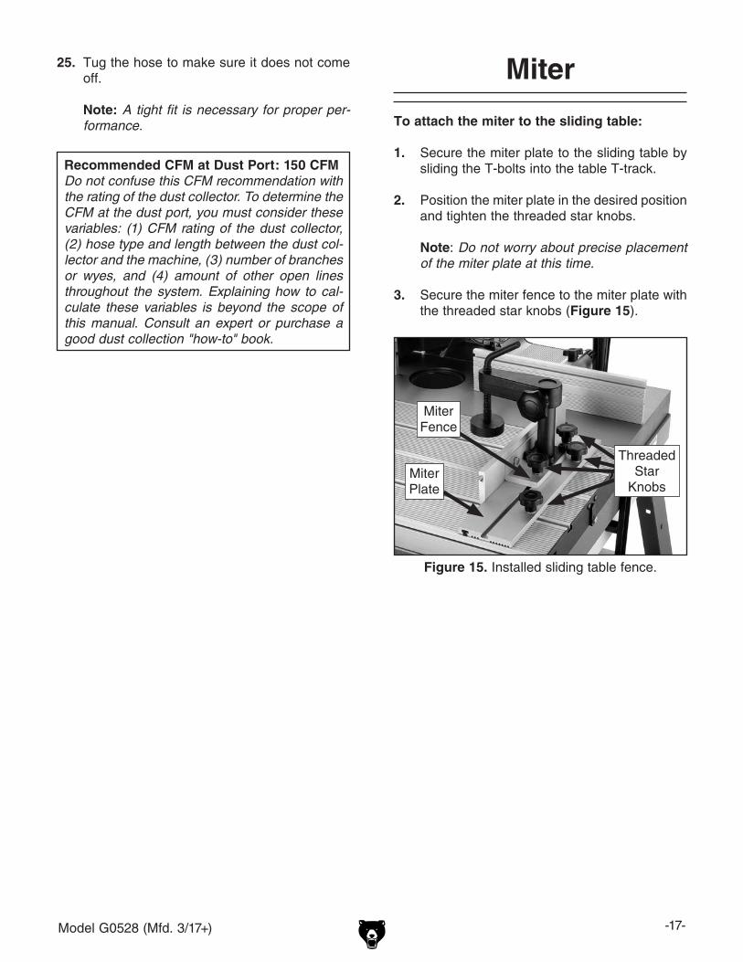
Figure 13. Installed hold-down assemblies.
Workpiece Hold-Down Assemblies
Threaded Star Knobs
DO NOT operate the Model G0528 without an adequate dust collection system. This saw creates substantial amounts of wood dust while operating. Failure to use a dust collec-tion system can result in short and long-term respiratory illness.
13. Verify fence face alignment shown in Figure 12 using a straightedge. If the fence faces are out of alignment when fully retracted into their housings, loosen the fence housing lock nuts and slide the fence face back into alignment.
14. Remove one of the hex nuts from each of the hold-down brackets.
15. Slide the hold-down brackets through the mounting holes on the dust cover and secure them from the underside of the dust cover with the hex nuts removed in Step 14.
16. Tighten the hex nuts until the hold-down brackets are secure.
17. Secure the hold-down fingers to the hold-down brackets by tightening the threaded star knob (Figure 13).
Note: Do not worry about precise placement of the hold-down brackets or fingers at this time.
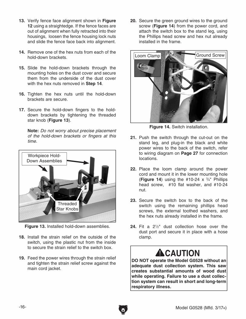
20. Secure the green ground wires to the ground screw (Figure 14) from the power cord, and attach the switch box to the stand leg, using the Phillips head screw and hex nut already installed in the frame.
21. Push the switch through the cut-out on the stand leg, and plug-in the black and white power wires to the back of the switch, refer to wiring diagram on Page 27 for connection locations.
22. Place the loom clamp around the power cord and mount it in the lower mounting hole (Figure 14) using the #10-24 x 3⁄4" Phillips head screw, #10 flat washer, and #10-24 nut.
23. Secure the switch box to the back of the switch using the remaining phillips head screws, the external toothed washers, and the hex nuts already installed in the frame.
24. Fit a 21⁄2" dust collection hose over the dust port and secure it in place with a hose clamp.
Figure 14. Switch installation.
Loom Clamp Ground Screw
18. Install the strain relief on the outside of the switch, using the plastic nut from the inside to secure the strain relief to the switch box.
19. Feed the power wires through the strain relief and tighten the strain relief screw against the main cord jacket.
Model G0528 (Mfd. 3/17+) -17-
Recommended CFM at Dust Port: 150 CFMDo not confuse this CFM recommendation with the rating of the dust collector. To determine the CFM at the dust port, you must consider these variables: (1) CFM rating of the dust collector, (2) hose type and length between the dust col-lector and the machine, (3) number of branches or wyes, and (4) amount of other open lines throughout the system. Explaining how to cal-culate these variables is beyond the scope of this manual. Consult an expert or purchase a good dust collection "how-to" book.
Miter
To attach the miter to the sliding table:
1. Secure the miter plate to the sliding table by sliding the T-bolts into the table T-track.
2. Position the miter plate in the desired position and tighten the threaded star knobs.
Note: Do not worry about precise placement of the miter plate at this time.
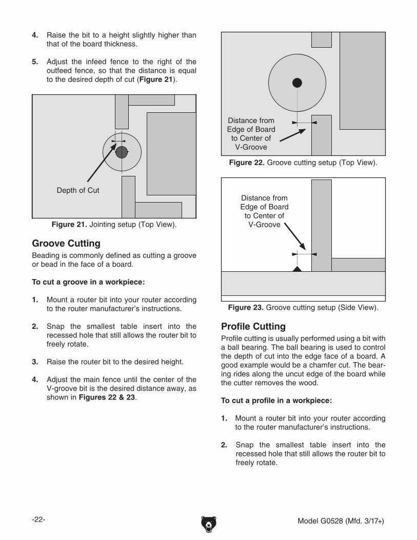
3. Secure the miter fence to the miter plate with the threaded star knobs (Figure 15).
Figure 15. Installed sliding table fence.
Miter Fence
Miter Plate
Threaded Star
Knobs
25. Tug the hose to make sure it does not come off.
Note: A tight fit is necessary for proper per-formance.

-18- Model G0528 (Mfd. 3/17+)
Router
To attach the router to the table:
1. Lift the table assembly up and engage the table braces on each side. Ensure that the table brace lock tabs are engaged completely around the lock screws (Figure 16).
Figure 16. Locked table brace.
Locked Position
Lock Screw
Table Brace Lock Tab
2. Move the jack bolt lock nut (Figure 17) on the router clamp to the table side of the router clamp if the router base mounting is 1⁄2" or thinner.
Figure 17. Router clamp lock nut positions.
Thick-Base Routers
Thin-Base Routers
Jack Bolt Lock Nut
Figure 19. Router clamp jack bolts.
4. Loosen the router clamps enough to allow the base of the router to press flat against the underside of the cast iron table.
Note: The router spindle should be centered under the cut out in the cast iron table.
5. Adjust the jack bolts and the lock nuts on each of the router clamps to allow the router base to be secured against the table (Figure 19).
6. Tighten the router clamps to secure the router base into position.
3. Slide each of the four router clamps into the T-slots on the underside of the cast iron table (Figure 18).
Figure 18. Installing the four router clamps.
Router Clamps
Jack Bolt
Hands and fingers can become seriously injured if they are pinched between the stand edge and the table. DO NOT place hands or fingers near the stand edge while the table is in the raised position.

Model G0528 (Mfd. 3/17+) -19-
Test Run
Once the assembly is complete, test run your machine to make sure it runs properly.
If, during the test run, you cannot easily locate the source of an unusual noise or vibration, stop using the machine immediately and refer to your router manual for troubleshooting.
If you still cannot remedy a problem with the Model G0528 router table, contact our Tech Support at (570) 546-9663 for assistance.
To test run the machine:
1. Put on safety glasses and hearing protec-tion.
2. Make sure the router table is turned OFF and disconnected from power.
3. Make sure the router collet nut is secure on the router spindle and will not come off during the test run.
4. Make sure the router is firmly secured to the table, and plug the router power cord into the router table outlet.
5. On the router, turn the power switch ON.
6. Connect the router table to power.
7. Make sure you have read the safety instruc-tions at the beginning of the manual and that the machine is setup properly.
8. Make sure all tools and objects used during setup are cleared away from the machine.
9. Turn the router table switch ON.
10. Listen to and watch for abnormal noises or actions. The router should run smoothly with little or no vibration or rubbing noises.
— Strange or unusual noises must be inves-tigated and corrected before operating the machine further. Always disconnect the machine from power when investigating or correcting potential problems.
11. Turn the router table OFF.

-20- Model G0528 (Mfd. 3/17+)
Damage to your eyes, lungs, and ears could result from using this machine without proper protective gear. Always wear safety glasses, a respirator, and hearing protection when operating this machine.
SECTION 4: OPERATIONS
NOTICEIf you have never used this type of machine or equipment before, WE STRONGLY REC-OMMEND that you read books, review industry trade magazines, or get formal training before beginning any projects. Regardless of the content in this section, Grizzly Industrial will not be held liable for accidents caused by lack of training.
Loose hair, clothing, or jewelry could get caught in machinery and cause serious personal injury. Keep these items away from moving parts at all times to reduce this risk.
Operation Overview
This overview gives you the basic process that happens during an operation with this machine. Familiarize yourself with this process to better understand the remaining parts of the Operation section.
To complete a typical operation, the operator does the following:
1. Examines the workpiece to make sure it is suitable for cutting.
2. Adjusts the fence close to the cutter for maxi-mum workpiece support near the cutter, and then locks the infeed and outfeed fence in place.
3. Adjusts the cutter height for the desired cut-ting profile location.
4. Adjusts the fence depth for the depth of cut.
5. Wears safety glasses and a respirator, and locates push sticks if needed.
6. If using a reversible router, the woodworker verifies the direction router operation is cor-rect, and then starts the router.
7. Holds the workpiece firmly and flatly against both the sliding table and fence, and then pushes the workpiece into the cutter at a steady and controlled rate until the workpiece moves completely beyond the cutter.
The operator is very careful to keep the workpiece firmly against the table and fence during the entire cut. For smaller workpieces or odd-shaped workpieces, the miter and clamp can be used, or a special jig can be made to hold the workpiece.
8. Stops the machine.
To reduce your risk of serious injury, read this entire manual BEFORE using machine.

Model G0528 (Mfd. 3/17+) -21-
Workpiece Inspection
Some workpieces are not safe to cut or may require modification before routing. Before rout-ing, inspect all workpieces for the following:
• Material Type This machine is intended for cutting natural
and man-made wood products, laminate cov-ered wood products, and some plastics. This machine is NOT designed to cut metal, glass, stone, tile, etc.
• Foreign Objects Nails, staples, dirt, rocks and other foreign
objects are often embedded in wood. While shaping, these objects can become dis-lodged and hit the operator, cause kickback, or break the blade, which might then fly apart. Always visually inspect your workpiece for these items. If they can't be removed, DO NOT cut the workpiece.
• Large/Loose Knots Loose knots may dislodge during a cutting
operation. Knots can cause kickback and machine damage. Choose workpieces that do not have large/loose knots or plan ahead to avoid shaping through them.
• Wet or "Green" Stock Shaping wood with a moisture content over
20% causes unnecessary wear on the cut-ters, increases the risk of kickback, and yields poor results.
• Excessive Warping Workpieces with excessive cupping, bowing,
or twisting are dangerous to cut because they are unstable and often unpredictable when being shaped. DO NOT process workpieces with these characteristics!
• Minor Warping Workpieces with slight cupping can be safe-
ly supported if the cupped side is facing the table or the fence. On the contrary, a workpiece supported on the bowed side will rock during a cut and could cause kickback or severe injury.
Routing operations on your Model G0528 are grouped into three main techniques:
• Edge Jointing• Groove Cutting• Profile Cutting
Edge JointingJointing the edge of a board involves using a straight cutting router bit to remove wood from the edge face of a board. The result is a perfectly flat and square edge.
To joint the edge of a workpiece:
1. Secure a straight cutting router bit into your router according to the router manufacturer’s instructions.
2. Snap the smallest table insert into the recessed hole that still allows the router bit to freely rotate.
3. Adjust the outfeed fence even with the left edge of the router bit (Figure 20).
Figure 20. Jointing setup(Top View).
Routing
-22- Model G0528 (Mfd. 3/17+)
4. Raise the bit to a height slightly higher than that of the board thickness.
5. Adjust the infeed fence to the right of the outfeed fence, so that the distance is equal to the desired depth of cut (Figure 21).
Figure 21. Jointing setup (Top View).
Groove CuttingBeading is commonly defined as cutting a groove or bead in the face of a board.
To cut a groove in a workpiece:
1. Mount a router bit into your router according to the router manufacturer’s instructions.
2. Snap the smallest table insert into the recessed hole that still allows the router bit to freely rotate.
3. Raise the router bit to the desired height.
4. Adjust the main fence until the center of the V-groove bit is the desired distance away, as shown in Figures 22 & 23.
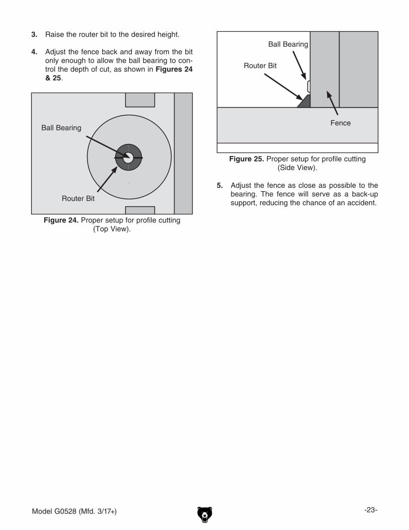
Figure 22. Groove cutting setup (Top View).
Profile CuttingProfile cutting is usually performed using a bit with a ball bearing. The ball bearing is used to control the depth of cut into the edge face of a board. A good example would be a chamfer cut. The bear-ing rides along the uncut edge of the board while the cutter removes the wood.
To cut a profile in a workpiece:
1. Mount a router bit into your router according to the router manufacturer’s instructions.
2. Snap the smallest table insert into the recessed hole that still allows the router bit to freely rotate.
Figure 23. Groove cutting setup (Side View).
Distance from Edge of Board
to Center of V-Groove
Depth of Cut
Distance from Edge of Board
to Center of V-Groove
Model G0528 (Mfd. 3/17+) -23-
3. Raise the router bit to the desired height.
4. Adjust the fence back and away from the bit only enough to allow the ball bearing to con-trol the depth of cut, as shown in Figures 24 & 25.
Figure 24. Proper setup for profile cutting(Top View).
Figure 25. Proper setup for profile cutting(Side View).
5. Adjust the fence as close as possible to the bearing. The fence will serve as a back-up support, reducing the chance of an accident.
Ball Bearing
Ball Bearing
Router Bit
Fence
Router Bit

-24- Model G0528 (Mfd. 3/17+)
SECTION 5: ACCESSORIESG1163P—1HP Dust CollectorEffective dust collection not only keeps your shop cleaner and more pleasant to work in, it can also keep you healthier. Our systems feature powerful motors and convenient collection bags - so they're ideal for just about any-sized woodworking opera-tion.
Figure 26. G1163P 1HP dust collector.
Figure 27. G2370 SHOP FOX® Board Buddies.
G2370—SHOP FOX® Board BuddiesThese unique holddowns only turn in one direc-tion to prevent kickback. Adjustable height, spring loaded wheels are designed to hold your workpiece tight against the table and rip fence and are made of a special composition that will not mark your work.
H3168—30 Pc. Carbide 1/4" Router Bit Set
Figure 28. Model H3168 30 pc. 1⁄4" shank router bit set.
G8983—Tilting Roller StandAdjusts from 26" to 44", 0º-45º. 150 lb. capacity.G8984—Single Roller StandAdjusts from 26 5⁄8" to 45". 250 lb. capacity.G8985—5 Roller StandAdjusts from 26" to 445⁄8". 250 lb. capacity.These super heavy-duty roller stands feature con-venient hand knobs for fast height adjustment.
Figure 29. SHOP FOX® Roller Stands.
G8983
G8984
G8985

Model G0528 (Mfd. 3/17+) -25-
SECTION 6: MAINTENANCE
Always disconnect power to the machine before performing maintenance. Failure to do this may result in serious person-al injury.
For optimum performance from your machine, follow this maintenance schedule and refer to any specific instructions given in this section.
Daily Check:• Loose router mounting clamps.• Damaged router bits.• Worn or damaged power cords.• Loose fence mounting or hardware.• Any other unsafe condition.
Schedule
Cleaning the Model G0528 is relatively easy. Vacuum excess wood chips and sawdust, and wipe off the remaining dust with a dry cloth. If any resin has built up, use a resin dissolving cleaner to remove it. Treat all unpainted cast iron and steel with a non-staining lubricant after cleaning.
Cleaning
Protect the unpainted cast iron surfaces on the table by wiping the table clean after every use—this ensures moisture from wood dust does not remain on bare metal surfaces.
Keep tables rust-free with regular applications of products like G96® Gun Treatment, SLIPIT®, or Boeshield® T-9.
Unpainted Cast Iron

-26- Model G0528 (Mfd. 3/17+)
SHOCK HAZARD. Working on wiring that is con-nected to a power source is extremely dangerous. Touching electrified parts will result in personal injury including but not limited to severe burns, electrocution, or death. Disconnect the power from the machine before servicing electrical com-ponents!
MODIFICATIONS. Modifying the wiring beyond what is shown in the diagram may lead to unpre-dictable results, including serious injury or fire. This includes the installation of unapproved after-market parts.
WIRE CONNECTIONS. All connections must be tight to prevent wires from loosening during machine operation. Double-check all wires dis-connected or connected during any wiring task to ensure tight connections.
CIRCUIT REQUIREMENTS. You MUST follow the requirements at the beginning of this manualwhen connecting your machine to a power source.
WIRE/COMPONENT DAMAGE. Damaged wires or components increase the risk of serious per-sonal injury, fire, or machine damage. If you notice that any wires or components are damaged while performing a wiring task, replace those wires or components.
MOTOR WIRING. The motor wiring shown inthese diagrams is current at the time of printingbut may not match your machine. If you find thisto be the case, use the wiring diagram inside the motor junction box.
CAPACITORS/INVERTERS. Some capacitorsand power inverters store an electrical charge for up to 10 minutes after being disconnected from the power source. To reduce the risk of being shocked, wait at least this long before working on capacitors.
EXPERIENCING DIFFICULTIES. If you are expe-riencing difficulties understanding the information included in this section, contact our Technical Support at (570) 546-9663.
Wiring Safety Instructions
The photos and diagrams included in this section are best viewed in color. You can view these pages in color at www.grizzly.com.
These pages are current at the time of printing. However, in the spirit of improvement, we may make chang-es to the electrical systems of future machines. Compare the manufacture date of your machine to the one stated in this manual, and study this section carefully.
If there are differences between your machine and what is shown in this section, call Technical Support at (570) 546-9663 for assistance BEFORE making any changes to the wiring on your machine. An updated wiring diagram may be available. Note: Please gather the serial number and manufacture date of your machine before calling. This information can be found on the main machine label.
SECTION 8: WIRINGmachine

Model G0528 (Mfd. 3/17+) -27-READ ELECTRICAL SAFETY ON Page 26!
Neutral
HotGround
110 VAC5-15 Plug
110 VAC5-15
Receptacle View this page in color at www.grizzly.com.
Ground
ToggleSwitch
Neutral
Hot
Ground
Switch Box
Wiring Diagram
Figure 30. Switch box.

-28- Model G0528 (Mfd. 3/17+)
304
313
303
311
307
308
312
315
142
323146V2
302
318-1
318 143 320319
301
145
305
230
314
317
337
147
308316
307230
308
307
333
142
139
142
306
228
136216
217
209
219
140
201
202218
140
212
210
211
203
144
335
314
324
310
215
307309
223
200
342
213
222
221
230
224
136135134
334123
129
112
126
137-1124
133
137131
132
314140
129
331
227
226
148
321322
127
119120
125
111
220
138
140
139
112
139
128
307
130
115
113
307
128
130
121
114
122
116
141
118117
230314
332
SECTION 8: PARTS
Main Breakdown

Model G0528 (Mfd. 3/17+) -29-
Parts List
REF PART # DESCRIPTION REF PART # DESCRIPTION111 P0528111 FENCE HALF 215 P0528215 TABLE LEFT SUPPORT112 P0528112 T-BOLT 1/4-20 X 1 216 P0528216 45˚ POSITIONER (LEFT)113 P0528113 MICRO-ADJUSTMENT ROD 217 P0528217 SPACER114 P0528114 FENCE BODY (LEFT) 218 P0528218 60MM INSERT PLATE115 P0528115 FENCE BODY GUARD 219 P0528219 GUARD116 P0528116 MICRO-ADJUSTMENT NUT 220 P0528220 29MM INSERT PLATE117 P0528117 HOLD-DOWN BRACKET 221 P0528221 MOTOR CLAMP PIECE118 P0528118 HOLD-DOWN 222 P0528222 HEX CLAMP SHAFT119 P0528119 L-BRACKET 223 P0528223 T-BOLT 1/4-20 X 2120 P0528120 KNOB BOLT 5/16-18 X 5/8 224 P0528224 HEX BOLT 1/4-20 X 1-1/2121 P0528121 HANDLE BOLT 3/8-16 X 3/4 226 P0528226 PHLP HD SCR M4-.7 X 10122 P0528122 HEX BOLT 3/8-16 X 1-1/2 227 P0528226 FLAT WASHER 4MM123 P0528123 FENCE PLATE 228 P0528228 TAP SCREW #10 X 1/2124 P0528124 CLAMP HOLDER 229 P0528229 HEX BOLT 1/4-20 X 1/2125 P0528125 DUST HOOD 230 P0528230 HEX NUT 1/4-20126 P0528126 SHORT FENCE 301 P0528301 FLOOR STAND127 P0528127 HEX NUT 1/2-12 302 P0528302 FRONT STAND (WITH SWITCH)128 P0528128 CLAMP PLATE 303 P0528303 UPPER ANGLE PLATE (LEFT)130 P0528130 HEAVY HANDLE 304 P0528304 MIDDLE PLATE131 P0528131 CLAMP BRACKET 305 P0528305 FRONT UPPER ANGLE PLATE132 P0528132 BRACKET 306 P0528306 RIGHT BRACKET133 P0528133 CLAMP ROD 307 P0528307 FLAT WASHER 5/16134 P0528134 HANDLE BOLT 1/4-20 X 5/8 308 P0528308 HEX NUT 5/16-18135 P0528135 CLAMP PLATE 309 P0528309 RUBBER STOP136 P0528136 PHLP HD SCR 10-24 X 3/8 310 P0528310 CAP SCREW 5/16-18 X 1-1/4137 P0528137 CAP SCREW 1/4-20 X 1/2 311 P0528311 LOCK WASHER 5/16137-1 P0528137-1 LOCK WASHER 1/4 312 P0528312 PAD138 P0528138 HEX BOLT 3/8-16 X 1 313 P0528313 PHLP HD SCR 1/4-20 X 1139 P0528139 LOCK NUT 1/4-20 314 P0528314 FLAT WASHER 1/4140 P0528140 HEX BOLT 1/4-20 X 1/2 315 P0528315 CARRIAGE BOLT 5/16-18 X 5/8141 P0528141 PHLP HD SCR 10-24 X 3/8 316 P0528316 LEFT BRACKET142 P0528142 HEX BOLT 5/16-18 X 1 317 P0528317 SWITCH143 P0528143 HEX NUT -20 318 P0528318 SWITCH BOX145 P0528145 LOCK NUT 5/16-18 318-1 P0528318-1 STRAIN RELIEF146V2 P0528146V2 EXT TOOTH WASHER #10 V2.03.17 319 P0528319 KEY SOCKET147 P0528147 PHLP HD SCR -20 X 1 320 P0528320 BLACK WIRE148 P0528148 LOCK PRESSURE PLATE 321 P0528321 WHITE WIRE200 P0528200 TABLE FRAME 322 P0528322 GROUND WIRE201 P0528201 SLIDING TABLE 323 P0528323 POWER WIRE202 P0528202 UPPER PLATE 324 P0528324 PHLP HD SCR 1/4-20 X 1-1/2203 P0528203 FIXED TABLE 332 P0528332 FENCE BODY (RIGHT)209 P0528209 SLIDEWAY 333 P0528333 UPPER ANGLE PLATE (RIGHT)210 P0528210 MIDDLE BRACKET 334 P0528334 RUBBER PLATE211 P0528211 SLIDE RAIL 335 P0528335 45˚ POSITIONER (RIGHT)212 P0528212 TABLE RIGHT SUPPORT 342 P0528342 T-BOLT 1/4-20 X 1213 P0528213 FIX PIECE

-30- Model G0528 (Mfd. 3/17+)
Labels and Parts List
Safety labels warn about machine hazards and ways to prevent injury. The owner of this machine MUST maintain the original location and readability of the labels on the machine. If any label is removed or becomes unreadable, REPLACE that label before using the machine again. Contact Grizzly at (800) 523-4777 or www.grizzly.com to order new labels.
330
330
329
327
326
328
331
REF PART # DESCRIPTION REF PART # DESCRIPTION326 P0528326 MACHINE ID/WARNING LABEL 329 PLABEL-12 READ MANUAL LABEL327 PLABEL-11 SAFETY GLASSES LABEL 330 P0528330 PINCH FINGERS LABEL328 PLABEL-14 ELECTRICITY LABEL 331 P0528331 GRIZZLY LABEL

CU
T A
LON
G D
OT
TE
D L
INE
Name _____________________________________________________________________________
Street _____________________________________________________________________________
City _______________________ State _________________________ Zip _____________________
Phone # ____________________ Email _________________________________________________
Model # ____________________ Order # _______________________ Serial # __________________
WARRANTY CARD
The following information is given on a voluntary basis. It will be used for marketing purposes to help us develop better products and services. Of course, all information is strictly confidential.
1. How did you learn about us? ____ Advertisement ____ Friend ____ Catalog ____ Card Deck ____ Website ____ Other:
2. Which of the following magazines do you subscribe to?
3. What is your annual household income? ____ $20,000-$29,000 ____ $30,000-$39,000 ____ $40,000-$49,000 ____ $50,000-$59,000 ____ $60,000-$69,000 ____ $70,000+
4. What is your age group? ____ 20-29 ____ 30-39 ____ 40-49 ____ 50-59 ____ 60-69 ____ 70+
5. How long have you been a woodworker/metalworker? ____ 0-2 Years ____ 2-8 Years ____ 8-20 Years ____20+ Years
6. How many of your machines or tools are Grizzly? ____ 0-2 ____ 3-5 ____ 6-9 ____10+
7. Do you think your machine represents a good value? _____Yes _____No
8. Would you recommend Grizzly Industrial to a friend? _____Yes _____No
9. Would you allow us to use your name as a reference for Grizzly customers in your area? Note: We never use names more than 3 times. _____Yes _____No
10. Comments: _____________________________________________________________________
_________________________________________________________________________________
_________________________________________________________________________________
_________________________________________________________________________________
____ Cabinetmaker & FDM____ Family Handyman____ Hand Loader____ Handy____ Home Shop Machinist____ Journal of Light Cont.____ Live Steam____ Model Airplane News____ Old House Journal____ Popular Mechanics
____ Popular Science____ Popular Woodworking____ Precision Shooter____ Projects in Metal____ RC Modeler____ Rifle____ Shop Notes____ Shotgun News____ Today’s Homeowner____ Wood
____ Wooden Boat____ Woodshop News____ Woodsmith____ Woodwork____ Woodworker West____ Woodworker’s Journal____ Other:

TAPE ALONG EDGES--PLEASE DO NOT STAPLE
FOLD ALONG DOTTED LINE
FOLD ALONG DOTTED LINE
GRIZZLY INDUSTRIAL, INC.P.O. BOX 2069BELLINGHAM, WA 98227-2069
PlaceStampHere
Name_______________________________
Street_______________________________
City______________State______Zip______
Send a Grizzly Catalog to a friend:

WARRANTY AND RETURNS
Grizzly Industrial, Inc. warrants every product it sells for a period of 1 year to the original purchaser from the date of purchase. This warranty does not apply to defects due directly or indirectly to misuse, abuse, negligence, accidents, repairs or alterations or lack of maintenance. This is Grizzly’s sole written warranty and any and all warranties that may be implied by law, including any merchantability or fitness, for any par-ticular purpose, are hereby limited to the duration of this written warranty. We do not warrant or represent that the merchandise complies with the provisions of any law or acts unless the manufacturer so warrants. In no event shall Grizzly’s liability under this warranty exceed the purchase price paid for the product and any legal actions brought against Grizzly shall be tried in the State of Washington, County of Whatcom.
We shall in no event be liable for death, injuries to persons or property or for incidental, contingent, special, or consequential damages arising from the use of our products.
To take advantage of this warranty, contact us by mail or phone and give us all the details. We will then issue you a “Return Number,’’ which must be clearly posted on the outside as well as the inside of the carton. We will not accept any item back without this number. Proof of purchase must accompany the merchandise.
The manufacturers reserve the right to change specifications at any time because they constantly strive to achieve better quality equipment. We make every effort to ensure that our products meet high quality and durability standards and we hope you never need to use this warranty.
Please feel free to write or call us if you have any questions about the machine or the manual.
Thank you again for your business and continued support. We hope to serve you again soon.
WARRANTY AND RETURNS