Model 2500 PalmSAT Operator’s Manual - Nonin Medical REP 5 Displays and Indicators Displays and...
37
Operator’s Manual Model 2500 PalmSAT ® Pulse Oximeter 0123 0123 English
Transcript of Model 2500 PalmSAT Operator’s Manual - Nonin Medical REP 5 Displays and Indicators Displays and...
Operator’s Manual
Model 2500 PalmSAT®
Pulse Oximeter
01230123 English
Nonin® reserves the right to make changes and improvements to this manual and the products it describes at any time, without notice or obligation.
Nonin Medical, Inc. 13700 1st Avenue North
Plymouth, Minnesota 55441-5443 USA
+1 (763) 553-9968(800) 356-8874 (USA and Canada)
Fax: +1 (763) 553-7807E-mail: [email protected]
Nonin Medical B.V. Prins Hendriklaan 26
1075 BD Amsterdam, Netherlands
+31 (0)13 - 79 99 040 (Europe)Fax: +31 (0)13 - 79 99 042E-mail: [email protected]
nonin.com
MPS, Medical Product Service GmbHBorngasse 20
D-35619 Braunfels, Germany
References to “Nonin” in this manual shall imply Nonin Medical, Inc.
Nonin, PalmSAT, PureLight and nVISION are registered trademarks or trademarks of Nonin Medical, Inc.
Microsoft® and Windows® are registered trademarks of Microsoft Corporation.
© 2014 Nonin Medical, Inc.7923-001-04
CAUTION: Federal law (USA) restricts this device to sale by or on the order of a licensed practitioner.
Consult Instructions for Use.
01230123
EC REP

Contents
Indications for Use ........................................................................................ 1Contraindications.................................................................................................... 1Warnings ................................................................................................................ 1Cautions ................................................................................................................. 2
Guide to Symbols .......................................................................................... 4
Displays and Indicators ................................................................................ 5SpO2 Display .......................................................................................................... 5Pulse Rate Display ................................................................................................. 5Pulse Quality Display.............................................................................................. 5Low Battery Indicator.............................................................................................. 5Sensor Fault or Inadequate Signal Display ............................................................ 5
Using the PalmSAT Pulse Oximeter ............................................................ 6Unpacking the Model 2500..................................................................................... 7Installing and Using the Batteries ........................................................................... 8Important Notes about Battery Use ........................................................................ 9
With AA Batteries................................................................................................ 9With Rechargeable NiMH Battery Pack .............................................................. 9
Recharging Batteries (NiMH Battery Pack only)................................................... 10Connecting the Sensor ......................................................................................... 10Power On/Off........................................................................................................ 10Power On Self-Test .............................................................................................. 10Monitoring............................................................................................................. 11
Detailed Operation....................................................................................... 12Setup Mode .......................................................................................................... 12
Entering Setup Mode ........................................................................................ 12Making Selections in Setup Mode..................................................................... 12
Care and Maintenance................................................................................. 14
Visual Indicators .......................................................................................... 15
Memory Functions....................................................................................... 16Memory Download................................................................................................ 16
Downloading the Data Stored in Memory ......................................................... 16Clearing the Memory ............................................................................................ 17
Clear Memory Mode ......................................................................................... 17Choosing Calendar and Clock Settings................................................................ 17
Communications.......................................................................................... 18Serial Output......................................................................................................... 18Connecting the Device into a Medical System ..................................................... 19
i
Contents (Continued)
Service, Support and Warranty...................................................................20Warranty................................................................................................................21
Parts and Accessories.................................................................................22
Troubleshooting ...........................................................................................23
Technical Information ..................................................................................25Manufacturer’s Declaration ...................................................................................25Equipment Response Time...................................................................................29Testing Summary ..................................................................................................30
SpO2 Accuracy Testing .....................................................................................30Pulse Rate Motion Testing.................................................................................30Low Perfusion Testing .......................................................................................30
Principles of Operation..........................................................................................30Specifications ........................................................................................................31
ii

iii
Figures Figure 1. Displays, Indicators and Buttons................................................................. 6Figure 2. Rear View.................................................................................................... 7Figure 3. Installing Batteries....................................................................................... 9Figure 4. Connecting a Sensor................................................................................. 10

iv
TablesTable 1. Labeling Symbols......................................................................................... 4Table 2. Adjustable Parameters and Settings.......................................................... 12Table 3. Pulse Oximeter Sensor Connector Pin Assignments................................. 18Table 4. Electromagnetic Emissions........................................................................ 25Table 5. Electromagnetic Immunity.......................................................................... 26Table 6. Guidance and Manufacturer’s Declaration—Electromagnetic Immunity.... 27Table 7. Recommended Separation Distances ....................................................... 28
Indications for Use
Indications for Use
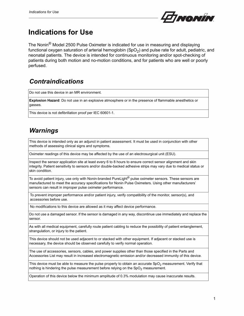
The Nonin® Model 2500 Pulse Oximeter is indicated for use in measuring and displaying functional oxygen saturation of arterial hemoglobin (SpO2) and pulse rate for adult, pediatric, and neonatal patients. The device is intended for continuous monitoring and/or spot-checking of patients during both motion and no-motion conditions, and for patients who are well or poorly perfused.
Contraindications
Do not use this device in an MR environment.
Explosion Hazard: Do not use in an explosive atmosphere or in the presence of flammable anesthetics or gasses.
This device is not defibrillation proof per IEC 60601-1.
Warnings
This device is intended only as an adjunct in patient assessment. It must be used in conjunction with other methods of assessing clinical signs and symptoms.
Oximeter readings of this device may be affected by the use of an electrosurgical unit (ESU).
Inspect the sensor application site at least every 6 to 8 hours to ensure correct sensor alignment and skin integrity. Patient sensitivity to sensors and/or double-backed adhesive strips may vary due to medical status or skin condition.
To avoid patient injury, use only with Nonin-branded PureLight® pulse oximeter sensors. These sensors are manufactured to meet the accuracy specifications for Nonin Pulse Oximeters. Using other manufacturers’ sensors can result in improper pulse oximeter performance.
To prevent improper performance and/or patient injury, verify compatibility of the monitor, sensor(s), and accessories before use.
No modifications to this device are allowed as it may affect device performance.
Do not use a damaged sensor. If the sensor is damaged in any way, discontinue use immediately and replace the sensor.
As with all medical equipment, carefully route patient cabling to reduce the possibility of patient entanglement, strangulation, or injury to the patient.
This device should not be used adjacent to or stacked with other equipment. If adjacent or stacked use is necessary, the device should be observed carefully to verify normal operation.
The use of accessories, sensors, cables, and power supplies other than those specified in the Parts and Accessories List may result in increased electromagnetic emission and/or decreased immunity of this device.
This device must be able to measure the pulse properly to obtain an accurate SpO2 measurement. Verify that nothing is hindering the pulse measurement before relying on the SpO2 measurement.
Operation of this device below the minimum amplitude of 0.3% modulation may cause inaccurate results.
1

Indications for Use
Discontinue use of adhesive tape strips if the patient exhibits an allergic reaction to the adhesive material.
Avoid excessive pressure to the sensor application site as this may cause damage to the skin beneath the sensor.
The device turns off after approximately 10 minutes when at critically low battery capacity.
Before changing the batteries, make sure the device is off and the sensor is not applied to a digit.
Cautions
Before use, carefully read the Instructions for Use provided with the sensors.
This device is not an apnea monitor.
Verify that all visible indicators illuminate during the startup (initialization) sequence. If any indicator is not lit, do not use the device. Contact Nonin Technical Service for assistance.
The presence of a defibrillator may interfere with the performance of this device.
This device may not work on all patients. If you are unable to achieve stable readings, discontinue use.
This device has motion tolerant software that minimizes the likelihood of motion artifact being misinterpreted as good pulse quality. In some circumstances, however, the device may still interpret motion as good pulse quality. Minimize patient motion as much as possible.
Ear Clip and Reflectance sensors are not recommended for pediatric or neonatal use. The accuracy of these sensors has not been established for pediatric or neonatal use.
Do not autoclave or immerse the device or sensors in liquid. Do not expose the device or components to excessive moisture or liquids.
Do not use caustic or abrasive cleaning agents on the device or the sensors.
The oximeter sensor might not work on cold extremities due to reduced circulation. Warm or rub the finger to increase circulation, or reposition the sensor.
Replace the batteries as soon as possible after a low-battery indication. Always replace the batteries with fully charged batteries.
Use only Nonin-specified battery types with this device.
Do not use fully charged and partially charged batteries at the same time. This may cause the batteries to leak.
Do not remove any covers other than the battery cover when replacing batteries. There are no user-serviceable parts inside other than the replaceable batteries.
Follow local, state and national governing ordinances and recycling instructions regarding disposal or recycling of the device and device components, including batteries.
Batteries may leak or explode if used or disposed of improperly.
Remove the batteries if the device will be stored for more than 1 month.
Warnings (Continued)
2

Indications for Use
This equipment complies with IEC 60601-1-2 for electromagnetic compatibility for medical electrical equipment and/or systems. This standard is designed to provide reasonable protection against harmful interference in a typical medical installation. However, because of the proliferation of radio-frequency transmitting equipment and other sources of electrical noise in healthcare and other environments, it is possible that high levels of such interference due to close proximity or strength of a source might disrupt the performance of this device. Medical electrical equipment needs special precautions regarding EMC, and all equipment must be installed and put into service according to the EMC information specified.
In compliance with the European Directive on Waste Electrical and Electronic Equipment (WEEE) 2002/96/EC, do not dispose of this product as unsorted municipal waste. This device contains WEEE materials; please contact your distributor regarding take-back or recycling of the device. If you are unsure how to reach your distributor, please call Nonin for your distributor’s contact information.
This device’s display will go blank after 10 seconds of inadequate signals. The data update period is every 1.5 seconds.
Portable and mobile RF communications equipment can affect medical electrical equipment.
This device is designed to determine the percentage of arterial oxygen saturation of functional hemoglobin. Factors that may degrade pulse oximeter performance or affect the accuracy of the measurement include the following:
A functional tester cannot be used to assess the accuracy of a pulse oximeter monitor or sensor.
All parts and accessories connected to the serial port of this device must be certified according to at least IEC 60950 or UL1950 for data-processing equipment.
This device is a precision electronic instrument and must be repaired by trained Nonin personnel only. Field repair of the device is not possible. Do not attempt to open the case or repair the electronics. Opening the case may damage the device and void the warranty.
Any sign or evidence of opening the system, field service by non-Nonin personnel, tampering, or any kind of misuse or abuse of the system, shall void the warranty in its entirety.
Replace batteries within 30 seconds to avoid losing settings (date, time, and patient data stored in memory) or corrupting data.
Radios and cell phones or similar devices can affect the equipment and must be kept at least 2 meters (6.5 feet) away from equipment.
Failure of a network data coupling (serial cable/connectors/wireless connections) will result in loss of data transfer.
Cautions (Continued)
- excessive ambient light- excessive motion- electrosurgical interference- blood flow restrictors (arterial catheters, blood pressure
cuffs, infusion lines, etc.)- moisture in the sensor- improperly applied sensor- incorrect sensor type
- inadequate signal- venous pulsations- anemia or low hemoglobin concentrations- cardiogreen and other intravascular dyes- carboxyhemoglobin- methemoglobin- dysfunctional hemoglobin- artificial nails or fingernail polish.
3

Guide to Symbols
4
Guide to Symbols
This table describes the symbols that are found on the Model 2500 and in this manual.
Table 1: Labeling Symbols
Symbol Description
Consult Instructions for Use.
Follow Instructions for Use.
Type BF Applied Part (Patient isolation from electrical shock).
UL Mark for Canada and the United States with respect to electric shock, fire, and mechanical hazards only in accordance with UL 60601-1 and CAN/CSA-C22.2 No. 601.1.
CE Marking indicating conformance to EC directive No. 93/42/EEC concerning medical devices.
Serial Number (located under the back cover).
IP32Protected against vertically falling water drops when enclosure is tilted up to 15 degrees and ingress of solid foreign objects greater than or equal to 2.5 mm (0.1 in.) in diameter per IEC 60529.
Indicates separate collection for electrical and electronic equipment (WEEE).
Authorized Representative in the European Community.
Manufacturer
%SpO2 %SpO2 Display
Pulse Rate Display
Pulse Quality Display
Low Battery LED
No Alarms
Front Panel Buttons
On/Off
Advance
CLASSIFIED
USC UL
01230123
SN
EC REP

Displays and Indicators
Displays and Indicators
SpO2 DisplayThe SpO2 display is the upper numeric display (identified by the %SpO2 symbol). This 3-digit light-emitting diode (LED) display shows the current oxygen saturation percentage.
Pulse Rate DisplayThe Pulse Rate display is the lower numeric display (identified by the symbol). This 3-digit LED display shows the pulse rate in pulses per minute.
Pulse Quality DisplayThe Pulse Quality display (identified by the symbol) is a tricolor LED that blinks once for each detected pulse. The Pulse Quality display changes color to indicate changes in the pulse waveform signal that may affect the SpO2 data. It may blink green, amber or red.
• Green indicates a good pulse strength signal.
• Amber indicates a marginal pulse strength signal. To improve signal quality, reposition the sensor, try a different sensor type, reduce patient movement, or improve the site’s circulation.
• Red indicates an inadequate pulse strength signal. While the Pulse Quality display is red, SpO2 and pulse rate values are not updated. After about 10 seconds, the values are replaced with dashes, indicating that readings are not possible.
Low Battery IndicatorWhen batteries are critically low, the digital displays will go blank, and the Pulse Quality display will blink amber or red, but not green. After 10 minutes at critically low battery capacity, the pulse oximeter will shut off automatically.
Sensor Fault or Inadequate Signal DisplayIf the device determines that a sensor fault exists (a sensor disconnect, failure, misalignment or incompatibility with the monitor) or if a pulse oximeter sensor signal is no longer detected, a dash (-) appears in the leftmost position of the SpO2 display. The readings that are displayed will freeze for 10 seconds if the pulse oximeter sensor fault or the inadequate signal continues.
If the sensor fault or the inadequate signal is not corrected, the frozen readings and the dash in the leftmost position will be replaced by dashes in the middle of both the SpO2 and the Pulse Rate displays after 10 seconds.
When the sensor fault or the inadequate signal is corrected, the SpO2 and pulse rate displays will return to normal operation.
5
Using the PalmSAT Pulse Oximeter
Using the PalmSAT Pulse Oximeter
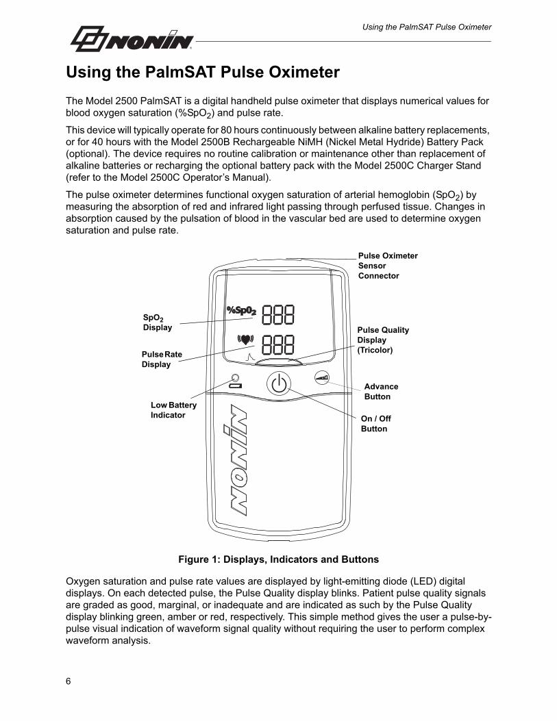
The Model 2500 PalmSAT is a digital handheld pulse oximeter that displays numerical values for blood oxygen saturation (%SpO2) and pulse rate.
This device will typically operate for 80 hours continuously between alkaline battery replacements, or for 40 hours with the Model 2500B Rechargeable NiMH (Nickel Metal Hydride) Battery Pack (optional). The device requires no routine calibration or maintenance other than replacement of alkaline batteries or recharging the optional battery pack with the Model 2500C Charger Stand (refer to the Model 2500C Operator’s Manual).
The pulse oximeter determines functional oxygen saturation of arterial hemoglobin (SpO2) by measuring the absorption of red and infrared light passing through perfused tissue. Changes in absorption caused by the pulsation of blood in the vascular bed are used to determine oxygen saturation and pulse rate.
Figure 1: Displays, Indicators and Buttons
Oxygen saturation and pulse rate values are displayed by light-emitting diode (LED) digital displays. On each detected pulse, the Pulse Quality display blinks. Patient pulse quality signals are graded as good, marginal, or inadequate and are indicated as such by the Pulse Quality display blinking green, amber or red, respectively. This simple method gives the user a pulse-by-pulse visual indication of waveform signal quality without requiring the user to perform complex waveform analysis.
SpO2 Display
On / Off Button
Pulse Quality Display (Tricolor)Pulse Rate
Display
Pulse Oximeter Sensor Connector
Advance Button
Low Battery Indicator
6

Using the PalmSAT Pulse Oximeter
The Model 2500 Pulse Oximeter may be used with a variety of Nonin-branded PureLight pulse oximeter sensors.
A sensor disconnect or malfunction is indicated by an inadequate Pulse Quality display blinking and/or a dash to the left of the SpO2 value on the LED display. When adequate pulse signals are not received, the SpO2 and/or pulse rate numerical values will be replaced by dashes. Low and critically low battery conditions will be indicated by the Low Battery indicator.
Figure 2: Rear View
Unpacking the Model 2500The Model 2500 complete system includes the following items:
• 1 Model 2500 Pulse Oximeter
• 1 Model 2500 Operator’s Manual on CD
• 1 Nonin Pulse Oximeter Sensor
• 4 AA-Size Alkaline Batteries
Confirm that the items listed are packed with the system. If any item on this list is missing or damaged, contact your distributor. Contact the carrier immediately if the shipping carton is damaged.
5822-000-05
UL 60601-1
US PATENT # Re.33,643
PULSE OXIMETERMODEL 2500
PLYMOUTH, MN USANONIN MEDICAL, INC.
4 X 1.5V AAIEC LR6
CLASSIFIED
USC UL 0123
IP32
30EM
See AccompanyingDocuments
Battery Cover Latch
Battery Cover
7

Using the PalmSAT Pulse Oximeter
Installing and Using the BatteriesThe Model 2500 can be powered by 4 AA-size alkaline batteries, or by the optional Rechargeable NiMH Battery Pack, Model 2500B.
When batteries are critically low, the digital displays will go blank, and the Pulse Quality display will blink amber or red, but not green. After 10 minutes at critically low battery capacity, the pulse oximeter will shut off automatically.
1. Press the battery cover latch, and remove the battery cover on the bottom of the unit.
2. Insert four new AA-size alkaline batteries or a Rechargeable NiMH Battery Pack. Be sure to insert the batteries in the correct position, as indicated by the polarity markings (+ and -) inside the battery compartment. Proper battery positioning is essential for correct operation.
3. Replace the battery cover and turn on the device. If the unit does not turn on, see “Troubleshooting.”
CAUTION: Use only Nonin-specified battery types with this device.
WARNING: The device turns off after approximately 10 minutes when at critically low battery capacity.
WARNING: Before changing the batteries, make sure the device is off and the sensor is not applied to a digit.
CAUTION: Replace the batteries as soon as possible after a low battery indication. Always replace the batteries with fully charged batteries.
CAUTION: Replace batteries within 30 seconds to avoid losing settings (date, time, and patient date stored in memory) or corrupting data.
!
!
!
8
Using the PalmSAT Pulse Oximeter
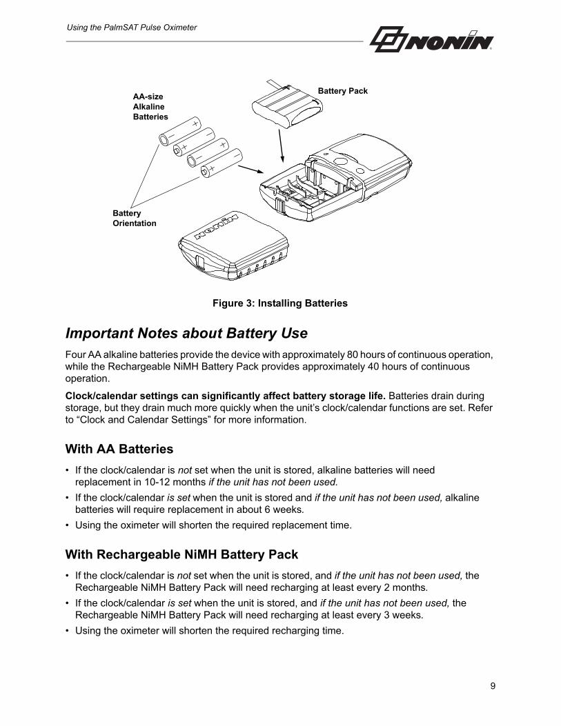
Figure 3: Installing Batteries
Important Notes about Battery UseFour AA alkaline batteries provide the device with approximately 80 hours of continuous operation, while the Rechargeable NiMH Battery Pack provides approximately 40 hours of continuous operation.
Clock/calendar settings can significantly affect battery storage life. Batteries drain during storage, but they drain much more quickly when the unit’s clock/calendar functions are set. Refer to “Clock and Calendar Settings” for more information.
With AA Batteries
• If the clock/calendar is not set when the unit is stored, alkaline batteries will need replacement in 10-12 months if the unit has not been used.
• If the clock/calendar is set when the unit is stored and if the unit has not been used, alkaline batteries will require replacement in about 6 weeks.
• Using the oximeter will shorten the required replacement time.
With Rechargeable NiMH Battery Pack
• If the clock/calendar is not set when the unit is stored, and if the unit has not been used, the Rechargeable NiMH Battery Pack will need recharging at least every 2 months.
• If the clock/calendar is set when the unit is stored, and if the unit has not been used, the Rechargeable NiMH Battery Pack will need recharging at least every 3 weeks.
• Using the oximeter will shorten the required recharging time.
Battery Orientation
AA-size Alkaline Batteries
Battery Pack
9

Using the PalmSAT Pulse Oximeter
Recharging Batteries (NiMH Battery Pack only)• Completely recharging the NiMH battery pack requires approximately 180 minutes when the
unit is completely discharged.
• The expected useful life of the Rechargeable NiMH battery pack is 500 charge/discharge cycles, or approximately 10 years, whichever is first. The battery pack must be charged at least once each year to maintain optimal battery life.
• AA alkaline batteries cannot be recharged in the charging stand.
Connecting the SensorConnect the pulse oximeter sensor (with the Nonin logo facing up) to the top of the device as shown. Ensure that the sensor is firmly plugged in. Refer to “Specifications” or to the specific sensor package insert for pulse oximeter sensor positioning information.
Figure 4: Connecting a Sensor
Power On/Off• Turn on the device by pressing and releasing the On/Off button on the front of the unit.
• Turn off the device by pressing and holding the On/Off button for approximately 2 seconds.
To conserve battery life, the device automatically powers off after 10 minutes of inactivity. Inactivity is indicated by dashes on the displays and may result from an improperly connected or positioned sensor, or from an inadequate patient pulse signal.
Power On Self-TestWhen the Model 2500 is turned on for normal operation, the unit will cycle through a startup/initialization sequence before displaying valid data. During startup, always check for any missing indicators or LED display segments. If any indicator is not functioning, do not use the device. Contact Nonin Technical Service for repair or replacement.
During its normal startup sequence, the device will cycle as follows:
• “888 888” appears briefly in the SpO2 and Pulse Rate displays.
• the amber Low Battery LED turns on steadily for a few seconds.
10
Using the PalmSAT Pulse Oximeter
• the Pulse Quality display turns red for 1 second, then green for 1 second, then shuts off.
• the clock time currently set in the memory (in hours and minutes, 04 41 for example) appears briefly in the displays.
• the software revision numbers (display in the following order, each for approximately 1 second): Main revision “r” + 3 digit; Memory revision “n” “n” (for m) + 3 digits.
• (two dashes) appear in the displays until a valid pulse signal is detected.
NOTE: This startup sequence varies slightly when entering setup mode at power on.
MonitoringVerify that the pulse oximeter sensor is properly positioned on the patient. Ensure that the pulse oximeter is sensing adequate pulse quality by:
• verifying that the Pulse Quality display is blinking green and
• verifying that the Pulse Rate and SpO2 displays are displaying readings and
• verifying that blinking of the Pulse Quality display is in time with the pulse rate for at least 10 seconds
If the Pulse Quality display is blinking red or amber or is blinking erratically, reposition the sensor or replace the sensor.
If the sensor is not properly positioned, or no sensor is attached to the pulse oximeter after startup (a few seconds after powering on), both the SpO2 and Pulse Rate displays will display a single dash until a valid pulse signal is detected.
11

Detailed Operation
Detailed Operation
All functions of the Model 2500 are controlled by the On/Off and Advance buttons located on the front of the unit.
Setup ModeSetup mode is used to set:
1. memory clear function,
2. calendar and clock, and
3. memory playback function.
In Setup mode, the Advance and On/Off buttons are used to make all selections.
NOTE: Setting the month to “00” disables the calendar and clock functions and helps conserve battery life.
Entering Setup Mode
1. With the unit off, press and hold the Advance button while pressing and then releasing the On/Off button.
2. Release the advance button when 888 888 is displayed on the SpO2 and Pulse Rate displays. The clock time currently set in the memory, 04 41 for example, appears briefly in the displays, and then CLr no appears.
Making Selections in Setup Mode
1. When entering Setup mode, CLr no is displayed. (This indicates the memory clear setting is being adjusted, and that the default value is “no.” See Table 2.) Press and release the Advance button to change the value for this setting (or press and hold the Advance button to scroll quickly through the range of adjustable values).
2. When the desired value appears, press and release the On/Off button to store the value and advance to the next adjustable parameter, as listed in the following table.
3. Continue this process until all settings are chosen.
When the setting sequence is complete, the device exits Setup mode, and is then ready to begin normal operation.
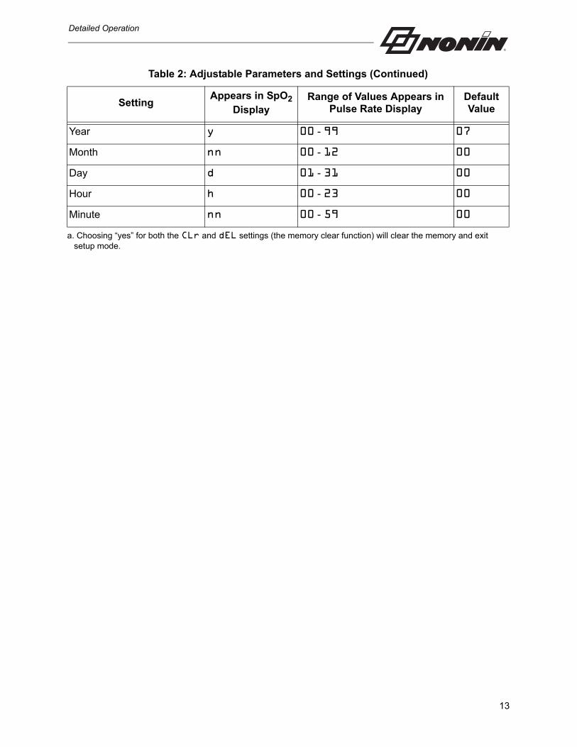
Table 2: Adjustable Parameters and Settings
SettingAppears in SpO2
DisplayRange of Values Appears in
Pulse Rate DisplayDefault Value
Memory Cleara CLr yes or no no
Delete (confirm clear) dEL yes or no no
12
Detailed Operation
Year y 00 - 99 07
Month nn 00 - 12 00
Day d 01 - 31 00
Hour h 00 - 23 00
Minute nn 00 - 59 00
a. Choosing “yes” for both the CLr and dEL settings (the memory clear function) will clear the memory and exit setup mode.
Table 2: Adjustable Parameters and Settings (Continued)
SettingAppears in SpO2
DisplayRange of Values Appears in
Pulse Rate DisplayDefault Value
13

Care and Maintenance
Care and Maintenance
Clean the device separately from the sensors. For instructions on cleaning pulse oximeter sensors, refer to the respective sensor instructions for use.
The OxitestPlus7 by Datrend Systems, Inc. can be used to verify operation of the pulse oximeter.
Clean the device with a soft cloth dampened with isopropyl alcohol. Do not pour or spray any liquids onto the device, and do not allow any liquid to enter any openings in the device. Allow the device to dry thoroughly before reusing.
CAUTION: Do not autoclave or immerse the device or sensors in liquid. Do not expose the device or components to excessive moisture or liquids.
CAUTION: Do not use caustic or abrasive cleaning agents on the device or the sensors.
!
!
14

Visual Indicators
Visual Indicators
The intended operator’s position for correctly perceiving a visual signal and its priority is 1 meter (3.3 feet).
The following table describes visual indicators and conditions.
Condition Visible Indication
Pulse Waveform Signal is inadequate
• Pulse Quality LED blinks red
• SpO2 and heart rate LEDs display dashes after 10 seconds
Sensor fault (i.e., sensor disconnect, failure, or incompatibility with the monitor)
• Pulse Quality LED blinks
• Dash (-) appears in the leftmost position of the SpO2 display
• SpO2 and Heart Rate numeric displays freeze for 10 seconds
Inadequate Signal (Sensor misalignment, ambient light, nail polish/artificial nails, etc.)
• Pulse Quality LED is blank
• Dash (-) appears in the leftmost position of the SpO2 display
• SpO2 and Heart Rate numeric displays freeze for 10 seconds
Inadequate SpO2 or pulse rate data (excessive motion or erratic heart rate, etc.) more than 20 seconds
• Dash (-) appears in SpO2 and pulse rate displays
Pulse rate data not updated for more than 30 seconds
• Pulse rate numeric display becomes dashes
Low Battery • Low Battery indicator is solid amber LED. No other displays are affected.
Critically Low Battery• Critically Low Battery indicator is flashing
• SpO2 and pulse rate LEDs are blank
• Pulse Quality display is solid red or amber
15
Memory Functions
Memory Functions
Each time the Model 2500 is turned on (except during Setup mode), data are automatically collected in memory. The device can collect and store up to 72 hours of SpO2 and pulse rate information.
NOTE: Only recording sessions longer than 1 minute are stored in memory. Memory will clear approximately 30 seconds after removing the batteries. Replace batteries immediately to avoid losing stored data.
Nonin’s nVISION data management software is available for use with Microsoft Windows operating systems.
The memory in the device functions as an “endless loop.” When the memory fills up, the unit begins overwriting the oldest data with the newest.
Each time the device is turned on, the current time/date information (if the clock is set correctly) is stored in memory to allow quick differentiation of recording sessions. Patient SpO2 and pulse rate are sampled and stored every 4 seconds.
Oxygen saturation values are stored in 1% increments in the range of 0 to 100%.
The stored pulse rate ranges from 18 to 300 pulses per minute. The stored values are in increments of 1 pulse per minute in the interval from 18 to 200 pulses per minute, and increments of 2 pulses per minute in the interval from 201 to 300 pulses per minute.
The last data recorded will be the first data printed. For example, the last 4 minutes of data recorded would be the first 4 minutes of printout.
Memory Download
NOTE: Downloading the data in memory does not clear the memory.
Downloading the Data Stored in Memory
1. With the unit off, press and hold the Advance button while pressing and then releasing the On/Off button .
2. Release the advance button when 888 888 is displayed on the SpO2 and pulse rate displays. The clock time currently set in the memory (04 41 for example) appears briefly in the displays, and then CLr no appears.
3. Data will be automatically downloaded from memory. Data is downloaded at a rate of 20 minutes of collected data per second. A 72-hour recording session (the maximum memory saved) is downloaded in approximately 3.5 minutes.
4. After downloading is complete, the device should be shut off before collecting new patient data.
5. The patient data is held in memory as long as the batteries are sufficiently charged. (See “Clearing the Memory” section.) To clear memory, use the memory clear function.
16
Memory Functions
Clearing the MemoryThe Memory Clear function allows you to delete all data currently stored in memory.
Clear Memory Mode
1. Enter Setup mode; CLr no will be displayed.
2. CLr may be set to no or yES.
• If no is entered in response to CLr (indicating that you do not want to clear the memory), the setup mode will continue directly to the calendar and clock settings. (Refer to “Clock and Calendar Settings.”)
• If yES is entered in response to CLr, then dEL will next appear in the SpO2 display, again with a choice of no or yES. This prompt gives you a second opportunity to avoid clearing the memory.
• Select CLr; use the Advance button to scroll through the values.• Use the On/Off button to accept a value and move to the next setting.
3. dEL may be set to no or yES.
• If no is entered in response to dEL (indicating that you do not want to clear the memory), the setup mode will continue directly to the calendar and clock settings. (Refer to “Choosing Calendar and Clock Settings.”)
• If yES is entered in response to dEL, (confirming that you do want to clear the memory), then dnE CLr will briefly appear in the displays indicating that the memory is cleared. The device will exit setup mode and is ready to begin normal operation.
• Select dEL; use the Advance button to scroll through the values.• Use the On/Off button to accept a value and move to the next setting.
Choosing Calendar and Clock Settings
NOTE: Setting the month to “00” disables the calendar and clock functions and helps conserve battery life.
1. After selecting no in the clear memory mode, y will appear in the SpO2 display.
2. Select the year, month, day, hour, and minute by scrolling the Advance button through the values. Use the On/Off button to accept a value and move to the next setting.
3. Press and release the On/Off button to exit setup mode.
When the calender and clock settings are complete, the device exits Setup mode, and is then ready to begin normal operation.
17

Communications
Communications
Serial OutputThe Model 2500 provides real-time data output capability via the pulse oximeter sensor connector (a 9-pin Sub-D connector). The pulse oximeter sensor connector pin assignments are listed below.
Information from the device, in the real-time mode, is sent in an ASCII serial format at 9600 baud with 9 data bits, 1 start bit, and 1 stop bit. The data are output at a rate of once per second.
NOTE: The 9th data bit is used for odd parity in memory download. In real-time mode, it is always set to the mark condition. Therefore, real-time data may be read as 8 data bits, no parity.
Real-time data may be printed or displayed by devices other than the pulse oximeter. On power up a header is sent identifying the format and the date and time. Thereafter, the data are sent once per second in the following format:
SPO2=XXX HR=YYY
where “XXX” represents the SpO2 value, and “YYY” represents the pulse rate. The SpO2 and pulse rate will be displayed as “---” if there are no data available for the data reading.
Table 3: Pulse Oximeter Sensor Connector Pin Assignments
Pin Number Assignment
1 1-Wire®
2 Infrared Anode, Red Cathode
3 Infrared Cathode, Red Anode
4 Serial Data, TTL Levels
5 Detector Anode
6 Sensor Type
7 Cable Shield (Ground)
8 No Connection
9 Detector Cathode, +5 V
18

Communications
Connecting the Device into a Medical SystemIncorporating the device into a medical system requires the integrator to identify, analyze, and evaluate the risks to patient, operators, and third parties. Subsequent changes to the medical system after device integration could introduce new risks and will require additional analysis. Changes to the medical system that must be evaluated include:
• Changing the system configuration
• Adding devices to or disconnecting devices from the system
• Updating or upgrading equipment connected to the system
Issues resulting from user-initiated system changes may include corruption or loss of data.
NOTES:
• When using the serial port to connect the device to other equipment, follow each device’s cleaning instructions.
• Verify all equipment connected to the device is suitable for the patient’s environment.
CAUTION: Failure of a network data coupling (serial cable/connectors/wireless connections) will result in loss of data transfer.!
19

Service, Support and Warranty
Service, Support and Warranty
The advanced digital circuitry within the Model 2500 requires no periodic maintenance or calibration. The device’s expected service life is 5 years. Nonin does not recommend field repair of the Model 2500. The circuit board in the Model 2500 is a multi-layer board using very narrow traces. Due to the very small trace size, extreme care must be used when replacing components to prevent permanent, non-repairable damage to the circuit board. Most components are surface-mounted and require special hot-air jet soldering and desoldering equipment. After any repairs are made, the Model 2500 must be tested to ensure correct operation.
For additional technical information, contact Nonin’s Technical Service department at:
Nonin Medical, Inc.13700 1st Avenue North
Plymouth, Minnesota 55441-5443 USA
(800) 356-8874 (USA and Canada) +1 (763) 553-9968
Fax: +1 (763) 553-7807E-mail: [email protected]
Nonin Medical B.V. Prins Hendriklaan 26
1075 BD Amsterdam, Netherlands
+31 (0)13 - 79 99 040 (Europe) Fax: +31 (0)13 - 79 99 042
E-mail: [email protected]
nonin.com
All non-warranty work shall be done according to Nonin standard rates and charges in effect at the time of delivery to Nonin. All repairs include a complete retest of the Model 2500 using factory test fixtures.
CAUTION: This device is a precision electronic instrument and must be repaired by trained Nonin personnel only. Field repair of the device is not possible. Do not attempt to open the case or repair the electronics. Opening the case may damage the device and void the warranty.
CAUTION: Any sign or evidence of opening the system, field service by non-Nonin personnel, tampering, or any kind of misuse or abuse of the system, shall void the warranty in its entirety.
!
!
20
Service, Support and Warranty
WarrantyNONIN MEDICAL, INCORPORATED, (Nonin) warrants to the purchaser, for a period of three years from the date of purchase, each Model 2500 Pulse Oximeter exclusive of sensors, cables, and batteries. (Refer to the individual package inserts for specific warranty information for sensors, cables, and other accessories.) Nonin shall repair or replace any Model 2500 found to be defective in accordance with this warranty, free of charge, for which Nonin has been notified by the purchaser by serial number that there is a defect, provided said notification occurs within the applicable warranty period. This warranty shall be the sole and exclusive remedy by the purchaser hereunder for any Model 2500 delivered to the purchaser which is found to be defective in any manner whether such remedies be in contract, tort or by law.
This warranty excludes cost of delivery to and from Nonin. All repaired units shall be received by the purchaser at Nonin's place of business. Nonin reserves the right to charge a fee for a warranty repair request on any device that is found to be within specifications.
The Model 2500 is a precision electronic instrument and must be repaired by knowledgeable and specially trained Nonin personnel only. Accordingly, any sign or evidence of opening the Model 2500, field service by non-Nonin personnel, tampering, or any kind of misuse or abuse of the Model 2500, shall void the warranty in its entirety.
All non-warranty work shall be done according to Nonin standard rates and charges in effect at the time of delivery to Nonin.
DISCLAIMER/EXCLUSIVITY OF WARRANTY:
THE EXPRESS WARRANTIES SET FORTH IN THIS MANUAL ARE EXCLUSIVE AND NO OTHER WARRANTIES OF ANY KIND, WHETHER STATUTORY, WRITTEN, ORAL, OR IMPLIED INCLUDING WARRANTIES OF FITNESS FOR A PARTICULAR PURPOSE OR MERCHANTABILITY SHALL APPLY.
21

Parts and Accessories
Parts and Accessories
For more information about Nonin parts and accessories:
• See the Parts and Accessories List on the Operator’s Manual CD.
• Contact your distributor or Nonin at (800) 356-8874 (USA and Canada), +1 (763) 553-9968, or +31 (0)13 - 79 99 040 (Europe).
• Visit www.nonin.com
Detailed information regarding specific sensor use (patient population, body/tissue, and application) can be found in the respective sensor Instructions for Use.
WARNING: The use of accessories, sensors, cables, and power supplies other than those specified in the Parts and Accessories List may result in increased electromagnetic emission and/or decreased immunity of this device.
WARNING: To avoid patient injury, use only with Nonin-branded PureLight® pulse oximeter sensors. These sensors are manufactured to meet the accuracy specifications for Nonin Pulse Oximeters. Using other manufacturers’ sensors can result in improper pulse oximeter performance.
22

Troubleshooting
Troubleshooting
Problem Possible Cause Possible Solution
The device won’t turn on.
The batteries are depleted. Replace all 4 batteries.
The batteries are installed incorrectly.
Verify battery orientation, illustrated inside the battery compartment or in Figure 3: Installing Batteries section of this operator’s manual.
A metal contact in the battery compartment is missing or damaged.
Contact Nonin Technical Service.
A dash appears in the leftmost position of the SpO2 display.
A sensor fault exists (disconnect, failure, misalignment, or incompatibility with the monitor).
Verify that the sensor is correctly connected to the device and the patient; replace sensor if the condition persists.
Dashes are displayed in both the SpO2 and Pulse Rate displays.
No signal is detected because the sensor is not plugged in.
Verify the sensor connections.
Sensor failure. Replace the sensor.
The displayed pulse rate does not correlate to the pulse rate displayed on the ECG monitor.
Excessive motion at the sensor site may be prohibiting the device from detecting a consistent pulse signal.
Eliminate or reduce the cause of the motion or reposition the sensor to a new sensor site.
The patient may have an arrhythmia resulting in some heart beats that do not detect a pulse quality signal at the sensor site.
Assess the patient.
A non-compatible sensor is being used.
Replace the sensor with a Nonin-branded PureLight sensor.
The ECG monitor may not be functioning properly.
Assess the patient.
An erratic Pulse Rate or an amber Pulse Quality display during the use with electrosurgical unit (ESU).
The ESU may be interfering with the pulse oximeter performance.
Assess the patient. Move the device, cables, and sensors as far away from the ESU as possible.
23
Troubleshooting
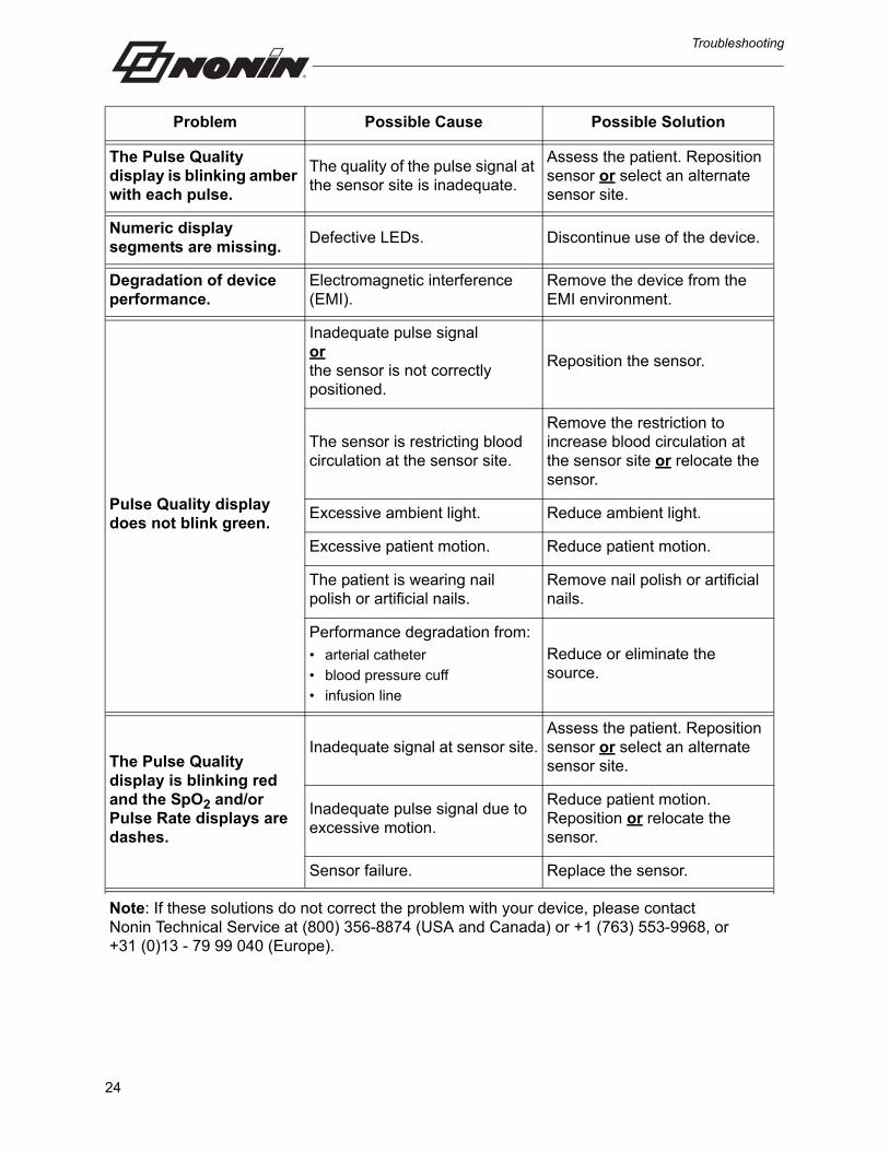
The Pulse Quality display is blinking amber with each pulse.
The quality of the pulse signal at the sensor site is inadequate.
Assess the patient. Reposition sensor or select an alternate sensor site.
Numeric display segments are missing.
Defective LEDs. Discontinue use of the device.
Degradation of device performance.
Electromagnetic interference (EMI).
Remove the device from the EMI environment.
Pulse Quality display does not blink green.
Inadequate pulse signalorthe sensor is not correctly positioned.
Reposition the sensor.
The sensor is restricting blood circulation at the sensor site.
Remove the restriction to increase blood circulation at the sensor site or relocate the sensor.
Excessive ambient light. Reduce ambient light.
Excessive patient motion. Reduce patient motion.
The patient is wearing nail polish or artificial nails.
Remove nail polish or artificial nails.
Performance degradation from:• arterial catheter
• blood pressure cuff
• infusion line
Reduce or eliminate the source.
The Pulse Quality display is blinking red and the SpO2 and/or Pulse Rate displays are dashes.
Inadequate signal at sensor site.Assess the patient. Reposition sensor or select an alternate sensor site.
Inadequate pulse signal due to excessive motion.
Reduce patient motion. Reposition or relocate the sensor.
Sensor failure. Replace the sensor.
Note: If these solutions do not correct the problem with your device, please contact Nonin Technical Service at (800) 356-8874 (USA and Canada) or +1 (763) 553-9968, or +31 (0)13 - 79 99 040 (Europe).
Problem Possible Cause Possible Solution
24

Technical Information
Technical Information
NOTE: This product complies with ISO 10993-1, Biological Evaluation of Medical Devices Part 1: Evaluation and Testing.
Manufacturer’s DeclarationRefer to the following table for specific information regarding this device’s compliance to IEC 60601-1-2.
CAUTION: A functional tester cannot be used to assess the accuracy of a pulse oximeter monitor or sensor.
CAUTION: All parts and accessories connected to the serial port of this device must be certified according to at least IEC Standard EN 60950 or UL 1950 for data-processing equipment.
CAUTION: Portable and mobile RF communications equipment can affect medical electrical equipment.
Table 4: Electromagnetic Emissions
Emissions Test Compliance Electromagnetic Environment—Guidance
This device is intended for use in the electromagnetic environment specified below. The user of this device should ensure that it is used in such an environment.
RF Emissions
CISPR 11
Group 1 This device uses RF energy only for its internal function. Therefore, its RF emissions are very low and are not likely to cause any interference in nearby electronic equipment.
RF Emissions
CISPR 11
Class B This device is suitable for use in all establishments, including domestic and those directly connected to the public low-voltage power supply network that supplies buildings used for domestic purposes.
Harmonic Emissions
IEC 61000-3-2
N/A
Voltage Fluctuations/Flicker Emissions
IEC 61000-3-3
N/A
!
!
!
25

Technical Information
Table 5: Electromagnetic Immunity
Immunity TestIEC 60601 Test
LevelCompliance Level
Electromagnetic Environment—Guidance
This device is intended for use in the electromagnetic environment specified below. The user of this device should ensure that it is used in such an environment.
Electrostatic Discharge (ESD)
IEC 61000-4-2
±6 kV contact
±8 kV air
±6 kV contact
±8 kV air
Floors should be wood, concrete, or ceramic tile. If floors are covered with synthetic material, the relative humidity should be at least 30%.
Electrical Fast Transient/Burst
IEC 61000-4-4
±2 kV for power supply lines
±1 kV for input/output lines
±2 kV for power supply lines
±1 kV for input/output lines
Mains power quality should be that of a typical commercial or hospital environment.
Surge
IEC 61000-4-5
±1 kV differential mode
±2 kV common mode
±1 kV differential mode
±2 kV common mode
Mains power quality should be that of a typical commercial or hospital environment.
Voltage dips, short interruptions, and voltage variations on power supply input lines
IEC 61000-4-11
±5% UT (>95% dip in UT) for 0.5 cycle
±40% UT (60% dip in UT) for 5 cycles
±70% UT (30% dip in UT) for 25 cycles
<5% UT (>95% dip in UT) for 5 sec.
±5% UT (>95% dip in UT) for 0.5 cycle
±40% UT (60% dip in UT) for 5 cycles
±70% UT (30% dip in UT) for 25 cycles
<5% UT (>95% dip in UT) for 5 sec.
Mains power quality should be that of a typical commercial or hospital environment. If the user of the device requires continued operation during power mains interruptions, it is recommended that the device be powered from an uninterruptible power supply or battery pack.
Power Frequency (50/60 Hz) Magnetic Field
IEC 61000-4-8
3 A/m 3 A/m Power frequency magnetic fields should be at levels characteristic of a typical location in a typical commercial or hospital environment.
Note: UT is the AC mains voltage before application of the test level.
26

Technical Information
Table 6: Guidance and Manufacturer’s Declaration—Electromagnetic Immunity
Immunity TestIEC 60601 Test
LevelCompliance
LevelElectromagnetic Environment—
Guidance
This device is intended for use in the electromagnetic environment specified below. The user of this device should ensure that it is used in such an environment.
Portable and mobile RF communications equipment should be used no closer to any part of the device, including cables, than the recommended separation distance calculated from the equation applicable to the frequency of the transmitter.
Recommended Separation Distance
Conducted RF
IEC 61000-4-6
3 Vrms
150 kHz to 80 MHz
3 V
Radiated RF
IEC 61000-4-3
3 V/m
80 MHz to 2.5 GHz
3 V/m
Radiated RF per ISO 9919 clause 36 and ISO 80601-2-61 clause 202.6.2.3
20 V/m
80 MHz to 2.5 GHz
20 V/m where P is the maximum output power rating of the transmitter in watts (W) according to the transmitter manufacturer and d is the recommended separation distance in meters (m).
Field strengths from fixed RF transmitters, as determined by an electromagnetic site surveya, should be less than the compliance level in each frequency range.b
Interference may occur in the vicinity of equipment marked with the following symbol:
a. Field strengths from fixed transmitters, such as base stations for radio (cellular/cordless) telephones and land mobile radios, amateur radio, AM and FM radio broadcast and TV broadcast cannot be predicted theoretically with accu-racy. To assess the electromagnetic environment due to fixed RF transmitters, an electromagnetic site survey should be considered. If the measured field strength in the location in which the device is used exceeds the applicable RF compliance level above, the device should be observed to verify normal operation. If abnormal performance is observed, additional measures may be necessary, such as reorienting or relocating the device.
b. Over the frequency range 150 kHz to 80 MHz, field strengths should be less than 3 V/m.
NOTES:
• At 80 MHz and 800 MHz, the higher frequency range applies.
• These guidelines may not apply in all situations. Electromagnetic propagation is affected by absorption and reflection from structures, objects, and people.
d 1.17 P=
d 1.17 P=
d 2.33 P=
27

Technical Information
Table 7: Recommended Separation Distances
This table details the recommended separation distances between portable and mobile RF communications equipment and this device.
This device is intended for use in an electromagnetic environment in which radiated RF disturbances are controlled. Users of this device can help prevent electromagnetic interference by maintaining a minimum
distance between portable and mobile RF communication equipment (transmitters) and the device as recommended below, according to maximum output power of the communications equipment.
Separation Distance According to Frequency of Transmitter
Rated Maximum Output Power of Transmitter W
150 kHz to 80 MHz 80 MHz to 800 MHz 800 MHz to 2.5 GHz
0.01 0.12 0.12 0.23
0.1 0.37 0.37 0.74
1 1.2 1.2 2.3
10 3.7 3.7 7.4
100 12 12 23
For transmitters rated at a maximum output power not listed above, the recommended separation distance d in meters (m) can be estimated using the equation applicable to the frequency of the transmitter, where P is the maximum output power rating of the transmitter in watts (W) according to the transmitter manufacturer.
NOTES:
• At 80 MHz and 800MHz, the separation distance for the higher frequency range applies.
• These guidelines may not apply in all situations. Electromagnetic propagation is affected by absorption and reflection from structures, objects, and people.
d 1.17 P= d 1.17 P= d 2.33 P=
28

Technical Information
Equipment Response TimeIf the signal from the sensor is inadequate, the last measured SpO2 and pulse rate values freeze for 10 seconds and are then replaced with dashes.
Example - SpO2 Exponential AveragingSpO2 decreases 0.75% per second (7.5% over 10 seconds)
Pulse Rate = 75 BPM Specific to this example:
• The response of the 4-beat average is 1.5 seconds.
SpO2 Values Average Latency
Standard/Fast Averaged SpO2 4 beat exponential 2 beats
Pulse Rate Values Response Latency
Standard/Fast Averaged Pulse Rate 4 beat exponential 2 beats
Equipment Delays Delay
Display Update Delay 1.5 seconds
60
65
70
75
80
85
90
95
100
0.0
8.0
16.0
24.0
32.0
40.0
48.0
56.0
64.0
72.0
80.0
Time in seconds
Sp
O2
SaO2 Reference 4 Beat Average
29
Technical Information
Testing SummarySpO2 accuracy, and low perfusion testing was conducted by Nonin Medical, Inc., as described below:
SpO2 Accuracy Testing
During motion and no-motion conditions at an independent research laboratory, SpO2 accuracy testing is conducted during induced hypoxia studies on healthy, male and female, non-smoking, light- to dark-skinned subjects that are 18 years of age and older. The measured arterial hemoglobin saturation value (SpO2) of the sensors is compared to arterial hemoglobin oxygen (SaO2) value, determined from blood samples with a laboratory co-oximeter. The accuracy of the sensors in comparison to the co-oximeter samples measured over the SpO2 range of 70 - 100%. Accuracy data is calculated using the root-mean-squared (Arms value) for all subjects, per ISO 80601-2-61, Medical Electrical Equipment—Particular requirements for the basic safety and essential performance of pulse oximeter equipment for medical use.
Pulse Rate Motion Testing
This test measures pulse rate oximeter accuracy with motion artifact simulation introduced by a pulse oximeter tester. This test determines whether the oximeter meets the criteria of ISO 80601-2-61 for pulse rate during simulated movement, tremor, and spike motions.
Low Perfusion Testing
This test uses an SpO2 Simulator to provide a simulated pulse rate, with adjustable amplitude settings at various SpO2 levels for the oximeter to read. The oximeter must maintain accuracy in accordance with ISO 80601-2-61 for heart rate and SpO2 at the lowest obtainable pulse amplitude (0.3% modulation).
Principles of OperationPulse oximetry is a non-invasive method that passes red and infrared light through perfused tissue and detects the fluctuating signals caused by arterial pulses. Well-oxygenated blood is bright red, while poorly oxygenated blood is dark red. The pulse oximeter determines functional oxygen saturation of arterial hemoglobin (SpO2) from this color difference by measuring the ratio of absorbed red and infrared light as volume fluctuates with each pulse.
30

Technical Information
Specifications
This device is not made with natural rubber latex.
Oxygen Saturation Display Range 0 to 100% SpO2
Pulse Rate Display Range 18 to 321 beats per minute (BPM)
Accuracy – Sensors Declared accuracy data for compatible sensors can be found in Nonin’s Sensor Accuracy document.
Measurement Wavelengths and Output Power*
Red: 660 nanometers @ 0.8 mW max. avg.
Infrared: 910 nanometers @ 1.2 mW max. avg.
Indicators
Pulse Quality Display: LED, tricolor
Numeric Displays: 3-digit 7-segment LEDs, red
Low Battery Indicator: LED, amber
Temperature (Operating) -20 to +50 °C (-4 to +122 °F)
Temperature (Storage/Transportation): -40 to +70 °C (-40 to +158 °F)
Humidity (Operating) 10 to 95% noncondensing
Humidity (Storage/Transportation): 10 to 95% noncondensing
Altitude (Operating) Up to 12,000 meters (40,000 feet)
Altitude (Hyperbaric Pressure): Up to 4 atmospheres
Power Requirements Four 1.5V AA-size alkaline batteries (80 hours typical operation) or NiMH rechargeable battery pack (40 hours typical operation)
Dimensions 13.8 cm H x 7.0 cm W x 3.2 cm D(5.4 in H x 2.8 in W x 1.3 in D)
Weight 210 g (7.4 oz) (with alkaline batteries) 230 g (8.1 oz) (with NiMH rechargeable battery pack)
Classifications per IEC 60601-1 / CAN/CSA-C22.2 No. 601.1 / UL60601-1
Type of Protection: Internally powered (on battery power)
Degree of Protection: Type BF-Applied Part
Mode of Operation: Continuous
Enclosure Degree of Ingress Protection IP32
* This information is especially useful for clinicians performing photodynamic therapy.
31