[mod Services Tevhnilcal informa'tion no; · [mod Services Tevhnilcal informa'tion ... proc'roment...
81
[mod Services Tevhnilcal informa'tion ~ge no; Zcaiuwe oi iur ltialted supply, you are requested to return this copy WHEN IT HAS SERVED c PURF'4(IE ID that It may be zrpde available to otheir requesters. Your cooperation will býe lpfret.WW. rNr noH INV £JjM'i> 4T'AA.~ Vg~ Iktitokjýjt j~~kO.[IUiI AWV WOW 0VIA~sI ~''1, t1110 4V 0-! r"i t ~I -Wi10. AN W u~~ AA1A W 1 "I''f i l 1* /AkvI vyl 011 #A*'%e'~ 1~~ 1" 4"l W%'V Or, *P1 AiPI 1"KO-0 Repro ba~a by Si P.1 VM EN I S I k IC, C[ENTER t0IK A&!N ~
Transcript of [mod Services Tevhnilcal informa'tion no; · [mod Services Tevhnilcal informa'tion ... proc'roment...

[mod Services Tevhnilcal informa'tion ~ge no;Zcaiuwe oi iur ltialted supply, you are requested to return this copy WHEN IT HAS SERVED
c PURF'4(IE ID that It may be zrpde available to otheir requesters. Your cooperationwill býe lpfret.WW.
rNr
noH
INV
£JjM'i> 4T'AA.~ Vg~ Iktitokjýjt j~~kO.[IUiI AWV WOW 0VIA~sI
~''1, t1110 4V 0-! r"i t ~I -Wi10. AN W u~~ AA1A W 1 "I''f i l 1* /AkvI vyl
011 #A*'%e'~ 1~~ 1" 4"l W%'V Or, *P1 AiPI 1"KO-0
Repro ba~a by
Si P.1 VM EN I S I k IC, C[ENTER
t0IK A&!N ~

~ADC rTlNICAL REPORT 4-1.9
"MFhNLER MOUNTED Of'YGE OR NITROGENGB4RTING AND CUARGI" PLA
Put. 1. D961gu1 Study
9, W-F. PARROW
AIR PRODUCTS, INGORPORATHO
BE4TAVlAB) LE CO
zji
BEST AVAILABLE COPY
1

When Gvvernment d~rawings, specifiocitiona, orotlhei data azc usad fo? vWt jurpose other thani Incomnwction with a definitely rese Goyaverrirtproc'roment operation, the United Statoe, Gov~rruntthereby inecr, no iis)fibllity nor any oJ~etior1
whatoev..ri&-dthe fact tha~t *..M Rmve2'nrint mayrhav fo ilsad$fvrniehy4d or in crty wVn aupplied
th* said drrwir~s, spoitioati'-a3, or ot~r data,ic not~ to he regardo4 by implication or otherivieus in awn' emianr licanaijie the huldez' or' wvoteperpon or copoi'@stions or conwoyinZ aniy r'ahto orpreI1eisaon to manufan'ture u1 or ceI ary I-at~ent~ooinvenrionm that may in any way t6 irla;t.4 thlefstt.
The tInfaaLlon turniallho herawith In=davalia2obI for stuft upon the %u erstmdiN~ Wht theQOYarlnet~t ts 1,roprietary intormota in and r"1AtinSt-heroto ahall niot 'he Jli:4red. It to desired thoitthe* Jittae A4vouait, (ff03) g Wwia1t Air Nvel~oyprnb~e ~Con~t4 1VrI tF.%tVEil Air Yam~ Ma~e Ohio be
the Ovwruilmc~t's ):ropM*"aR S"eresto and thoe
W&r IN

WADC TEOLNICAL REPOR F 54,19p at I
SEUTRANLER MOUNTED OXYGE.N OR NITROGENGENERATING AND CHARGING PLANT
P'zrt 1. Deulg Study
i,.;W, ipaerrw
Air Products. lucorajed
Cauambct No. AF 3J3(600- 198MRDO No, 660.17
,4iAir DuvJlopaent CanuSAlt Heeemmb and UtJ.lhpmftt Ceemad
Ualted Sutes Ai ForcUgdPaltamon Air Fome Du.e, OLia
U
*1
II
'
This report was prepard bY Air Products, Incorporated, Alleritcyn,Peniaylvaoia, on contract No. A? 33(6oo)-1Wg55, dated 9 June 1952;Supplement A&,reemen. No. I, dated 2 March 1953; and Reviaion 1, dated15 Yxy i-53. Work was aministered under the direction of C. h. Anderson,Vice-Pr 1U, ent-in-Ch argo-of-Engineering and Ha W. Farrow acted as projectengineer. The contrct was initiated under Research and Development(Order ho. 660-128, "Improvement and Developent of Oxyien GeneratingPlants and Au.aliary Equipment,O by ,he Equipment Laboratory, Directorateof Laboratoriess Wright Air Development Canter, wijth A. I. Paulson servingas poject engineer.
ThI D is one of a serles of throe reports to be issued on this project."The second report will be isaued upon completion of the operating testson the moolle, liluid oxygen generator, while tha third report will beissued upon completion of the entir-e pograms
Included awng those who cooper,ited in thA Fudjy were C. J. Schilling,L. L, Vollard, P. 0. Foýst, J. V. Fetterman of Air Products, Incorporated,
! 5
W&CT )-l 1

ABSTRACT
Denign of a mobile gpnerator capable of pruducinf, two tons per day ofhigh-rurity liquid oxygen 'or liquid nitrogen nnd capahle of comnressing theentire nrotdction capacity to 40-00 PSIG as described. Flows of the oneratingcycle are pictured and discussed. Material and heat balances are calculntedon the basis of theory and oast e%-erience gained from the fabrication ofmore than 500 oxygen generators, both mobile and stationary, of hi.gh- and low-purity type. Tentative scecifications for the equirnent comronents arf li3ted.
"1
P¶JDLICAT ION P•V•
The publioation of thizc .nc-rt-does not constitute approval b7 theAir Force of the fIndinss or thn concluaions contained thereine It ispubLished only for the exohange and stimulation of ideas.
FOR VTZ COMANUJPs
Colonoel UWAF
Chief, Equipment Laboratory
WADC ?R 54-19 PT I2iii

L
To obtain the desired rrodIetion of two tons pWi day of 99,5% 0re liqLdoxgen, or two tons per day of 99.0% p.ure lic•pid nitrogen, an air feed of ap-proiraately 1000 standard cubic feet per miniuit shall be used. This 5ha1 in-dicate a liquid oxyg"n recovery by weight of 4.29% or a Liquid nitrogen recov-ery by weight of 3.7%. To operate the unit; three dieuel igineu shall supplyapproximately 330 horsewhoer, which zhall result in a ratio of approximately161 pounds of liquid oxygen produoed per pound of diesel fuel burned. A tamp-erature approach of atyproximately 8•0 shall be exnected at-the air inlet emdof the heat exchanger. The estimated heat infiltration from ambient mArround.ings into the air qemarator shall be 1.5 B.T.U. per,-ound of air feed. It ise-ýtimated that the loss of air from the heat exchamner during the revereal•,whigh oecur every 10 mirttee, shall be 3% of the total input. The sesttrailershall be appro•imately 321-Q" long, 9'-6" wide and 12'-0" high. These dim-ensionh, which are reduced to a minin, shall be for the greater part, dic-tated by the Availability of equipment components in the air source section.
M 51
'S

CONThNTS
Page
FOREORD ii.
ABSTRACT iii
SUMMARY iv
SSZCTION I CYCLE OF ,AIR SEPARATION 1
F!gurep 1 Liquid Nitrcgen Cyclo 2
Figure 2, Liquid Oxygen Cycle 3
Figure 3 Gaseous Nitrogen Cycle 4
Figure 4 Gaseous Oxygen Cycle 5
SECTION II ELECTRIC PO'R ANID CONTIRCL 9
F.gure 5 Wiring Diagram 10
SKCTION III TH•r.ODYNAIC CALCULATIONS I1 -
Figurw 6 Liquid N2 Heat Balance -.
Figure 7- Liquid Vator Equilibriuim Curve 18
Figure 8 Liquid 02 Het 4 Balance 32
Figure 9 Gaseous Nitrogen Heat Balance 35
Figure 10 Gaseous Oxygen Hept Balance 38
SirTION IV E'JIP1EN' SPECIFICATIONS 41
Fig"re .1 Generator General Arrangement
SECTION V GEERATOR MASTER VALVE AND TEMPERATURE INDEX 64
WADC TR 54-19 K I v. I:
S?;GTIC I
CYL' OF Ain 31PAIATION
G1eneral.
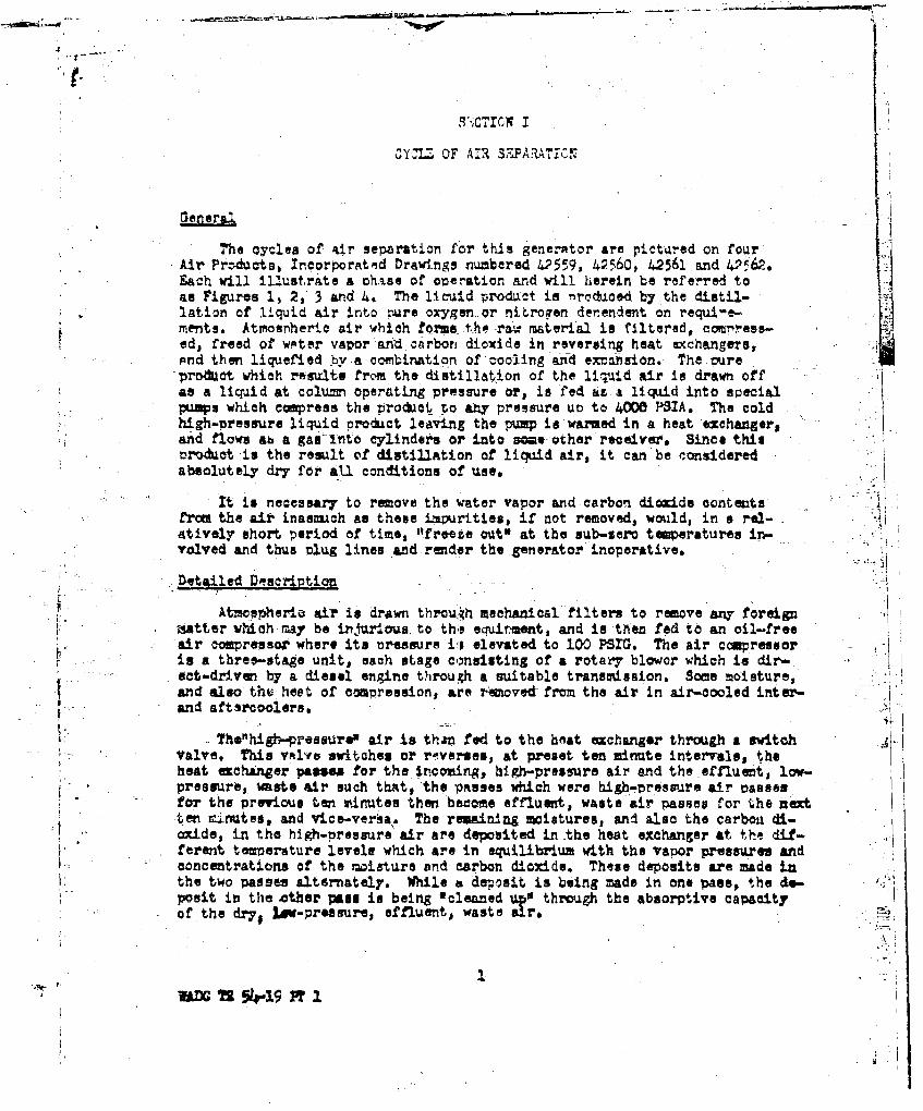
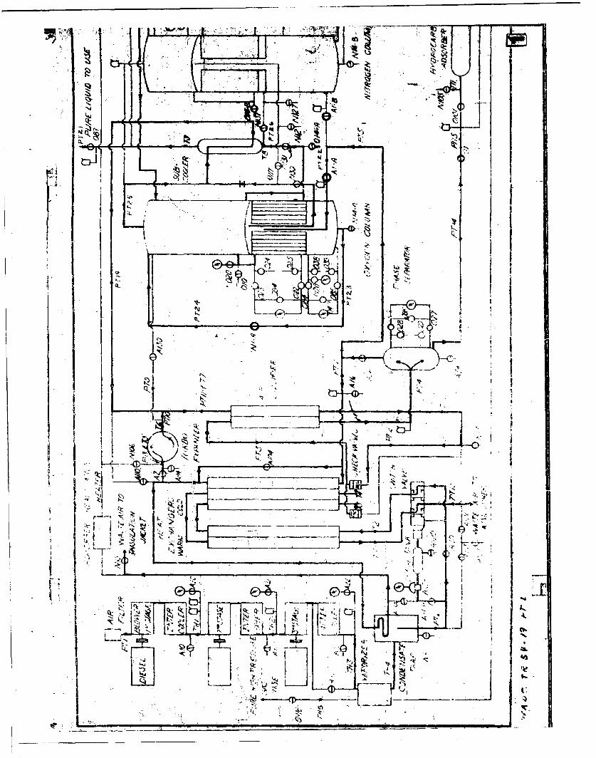
,he cycles of air separation for this generator are pict~red on fourAir Pro-cts, Incorporated Drawings numbered 02559, 42560, 42561 and 42562.Each will illustrate a chase of operation and will herein be referred toas Figures 1, 2, 3 and 4. The licuid product is nroduced by the distil-lation of liquid air into sure oxygen or nitrogen derendent on requi-e-ments. Atmospheric air which forms the raw material is filtered, CCMress-ed, freed of wpter vapor and carbon dioxide in reversing heat exchangers,And then liquefied by.a combination of cooling and exnmnsion. The pureproduct which results from the distillation of the liquid air is drawn offas a liquid at column operating pressure or, is fed as a liquid into special
umps which coepress the product to any pressure un to 4000 PSIA. the coldhigh-pressure liquid orodcEt leaving the pump io warmed in a heat exehanger,and flows aL a gas Into cylinders or into ==*e -ther receiver. Since thisnrouot 'is the reswlt of distillation of liquid air, it can be consideredabsolutely dry for aU, conditions of use.
it is necessary to remove the water vapor and carbon dioxide contenitsfr= the air inasmuch an these impurities, if not removed, would, in s rel-atively short period of time, ,freeze out' at the sub-sero temperatures in-volved and thus plug lines and render the generator inoperative.
•Detailed Descri2tiou
Atmospherio air is drawn throuth mechanical filters to remove any foreignmatter which may be injurioua, to this equinment, and is then fed to an oil-freeair compressor where its uresenre i ! elevated to 100 PSM. The air voressoris a three-stage unit, each stage c,mnslsting of a rotary blower which is dir-set-drivean by a diesel engine through a suitable transmission. Some moisture,and also thu heet of ooaressions are imoved from the air in air-cooled inter-and aftsrooolers.
The"high-pressurew air is tha"n fed to the hetat exchanger throegh a switchValve. This valve switches or raverses, at preset ten minute intervals, theheat echinger patses for the incoming, high-pressure air and the effluent, low-pressure, waste air such that, the passes which were bighi-ressure air vassesfor the previous ten minutes then become effluent, waste air passes for the nextten situtes, and vice-ver"a. The reaining moistures, and also the carboa di-oxide, in the high-oressure air are deposited in the heat exchanger at the dif--erent temperature levele which are in equilibrium with the vapor pressures andconcentrations of the w~isturs and carbon dioxide. These d"eAts are made inthe two passes alternately. While a deposit is being made in one pasel, the do-posit in the other ps is being *cleaned 'e through the absorptive capacityof the dry, lt-pressure, effluent, wasteare
I

ta I
joý
ztt
I.-Al

- -4
4± L44
CIDI
19
It041
IIi 44
7zIT
*ni
:2.Id-I
-- --[Io r Ir. .
-"A PI
-LH,
"T I
-- I
. . I ' 1
• ' •• • • •

f
A w
INAN
~Lj
r%. I
~W 7

44.-
*oil
biK ,
I- 0
43-Li0
. i
41
NO'
________ I
. '4, 4ki~

IIii
wlI________
* ~ !J
~VT~ ____ _____ ____ __4_
* I -;7
Z3 Q
t-4 ~ I:

-- U, L
D X
7 . . E
1w

II'After leaving the heat exchanger, the high-nressure air, which is then a
saturated vapor, enters the air liquefier. The liquefier is an extension ofthe heat exchanger surface, and in it, liquefaction of a nortion of the in-
coming air is effected. This portion is the amount of liquefaction necessaryto keep the cyle, operating, and it is equivalent to, (1) the amount of liquidwithdrawn as the final product plus, (2) the amount of liquid which is vavor-ised as a result of the influx of heat Into the generator from the ambient sur-roundings plus, (3) the amount of liquid which is lost as a result of the ex-pansion from high-oressure-air pressure to column onerating pressure, thepressuro, at which the liquid product is withdrawn,
The partially liquefied, high-pressure air then enters the phase separator,where its liquid and vapor pMases are divided and directed into different
The llqLiLd strsa is expanded to a roximately 6 PSI after which it is
passed throuh a silica gel ty-pe hydrocarbon adsorber. In the adsorber, removalof the hydrocarbon content is accomrlmshed to orevent their accu-alation todangerous ccncentrations in the distillation column. After every 150 or norehours of operation, the adsorber is reactivated by means of an electricallyheated stream of hot dry Air which abmorbs the hydrochrbons and carries themoff to atmosphere. This air is taoped from the air aunoly to the turbo expand-/ ! er.
After tne adsorber the liquid stream is fed to the sub-cooling Jackets ofthe lUiqad product pu••s to prevent vaporization of the pure liquid product whemthe pump is operating, and thus ieen the numu efficiency high. The stream isthen directed to the low cressure section of either the-nitrogen or oxygen col-"u= deperdIng em the final oroduct requirmLd.
The vAcor ph&:e Ls further divided into two streams. One of these, repre-senting ?59 of the total air feed, passes through the cold section if the heatexchanger from the cold end to the warmer end, and then feeds the turbo am-sander. The exhaust from the expander joins the ef flucnt waste air stream whichleaves the column and enters the air liquefier,
In the case of producing oxygen the other vapor stream from the nhase sep-arator is excanded through a wivle from high-pressure-air pressure to high-nress-ure column pressure, which is anrroximately 89 PSIA. This vamr enters the high-r.resure column and is fed directly into the condenser where all of it is con-densed by the prodct, liquid oxygen which surrounds the tubes on the low- ress-ure-columu side of the condenser. The resulting liquid is exoanded to low-nress-
, ture-coluw oressure and introduced into the low-pressure column at the top as
reflux. In order to prevent rare. inert gases such as neon, etc., which arefound in the air, and which are not capable of being condensed by the liquidoxygen, from blanketing the condenser tube surfaces and thus ircjair their effi-ciencies, a stream is drawn off from, the dome of the condenser and expanded intothe effluent waste air stream which leaves the colu-m. This non-concrenmAhle
offtake, although ¢er7 effective in accomplishing its., ur-,cas is so very smalliin magnitude that it does not enter into the calculations for the na'erial andheat balances.
The low-pressure column contains a number of bubble-cap sans of conventional
design, which are fed at the proner .oints by the exmnded liquid fr-im the
6VADC TR Z14-9 PT 1

incoming high-pressure Ur, and the xanded liquid from the high-rresssure col-
umn. The linuid descending on these pans comes into intimate cort•ct with theascending vazors resulting from the column feed. as well as the varors from thebollinq oxygen which surrounds the tu-es of the condenoer, Thia intirate con-tact of vauor and liquid on aich can results J*n a gradual vacorization of the
. more-volatile conatituent, nitrogen, and a condensation of the less-volatileconstituent, QX78en. Sutffci'"nt rans art included in the low-oressure coltirto ensure that the liquid withdrawn from the bottom is 99.5% pure c.-'en. Be-cause the boiling'rcint of argon is closer to the boIlin- coint of oxygen thanit is to the boilinpFmoint, of nitrogen, it appears in the colum in the vicin-.3 ity of the oxygen, and shows up as the 0.5% impurity in the nroduct oxygen,.
Since there is only one product, oxygen, withdrawn frrom the column, theremaining cxý-en and argon and all of the nitrogen leave the colunn at the tcj asa saturated vapor. This va;or passes through the oxygen subcooler where it sub-cools the product W~gen to prevent, or reduce "flash" losses resulting from
later emansion. After Passing through the subcooler, it combin"s with the turboexoander exOaust and enters the air liquefier where it liquefies a nortion of theincoming high-pressure air. From the air liquefier it passes through the heatexchanger where it both cools the incoming air to saturAtion temoerature, andabsorbs the moisture and carbon dioxide which were deposited by the inco•ing airduring the precedine ten-Mirnute switch Period. It finally exhausts to atmospherethrough the switch vqlve.
The product licraid oxygen is wtthlrawn fro,. the bottom of the low-nressurecolumn. It passes thrcugh the uubcooler where it is subcooled by the effluentwaste air to Prevent or reduce "flash"losses resulting from exnarsion into thereciprocating oxygen =uM, or into an external receiver. In the rump its press-ure is elevated to 4•0O PSTj and it is discharged through a heat exchanger orvaporizer in the dis:harge line of the third-stage blower where it is warmed toambient temperature.,
In the case of croducing nitrogen the other vanor stream from the Phaseseparator is exvqrded through a valbe from high-cressure-air oressure to high-
pressure column oressure, which is aoproximately 52.2 PSIý. The vacor entersthe high-pressure r.ntrogen colum. which contains a number of bubble-can pans ofconventional design. The ascending vcpor c=mes into intimate contact with liquiddescending on the pans. This intimate contact of vapor and liquid on each vanresults in a gradual vaporization of the more volatile constituent, nitrogen anda condensation of the less volatile constituent, oxygen, which is esanded intothe low pressure col%Lmn. The ascending vaoor enters the condenser where it iscondensed to a liquid nitrogen -'roduct by the crude oxygen product which surroundsthe tubes on the low pressure column side of the condenser. As in the cans ofoxygen produ:tlona small noncondennable stream is removed from the dome of theccndensor to prevent blanketing of the condenser surface.
The low oressure column consists essentiail! of s condenser and shell. Tne
* expanded crude oxyven from the high pressure column ard the expanded Aquid stream
• WA•C TR 541-19 F, 1

from the nrodjct rnm tncktts are introduced into the low uresaure column sideof the condenser. These streams are vaoorized b7 the 01ndensing nitrogen inthe high rr-ssuri c.;,=n and the rse•,ingr vapor passes through seve.ral on-trainment tras above the condenser in the lo: vressure cholim,SThe waste vahor frnm the low preiireg coluim passes through the subcoler,
After passing through the subhooler, it combines with the tur*to exp'dn-r exhaustand enters the air liquefier w'ilre it liquefies A vorticn of ths incoming high-pressurt air, From the air liqaefier it passes throug the h,,t exvhanger wnere-it bcth cools the incominR air to saturation teoerature, and absorbs the mois-
' ture an, carbon dioxide whJct' were dwposited by the inccC ng air ,rin.n the ore-ceding ten-midnute switch eeriod. It finally exhausts to atiosohere through theswitch valve.,
The product liclaid nitrogen is withdrawn from the bottom of the ccndenser.It vasses through the subcooler into the recivrocating nitrogen nmup, or intoan external receiver. In the 'up its preisure is elevated to i00 PSIA and itis discharged through a he&t exchanger or vaDori7.er In the discharge line of thethlrd-stage blower where it is warmed to ambient temperature,
Pressure gauges, liquid-level gauges ard tomrerature indicators are locatedtbroughout the system as necessary to s9rve as operating aids. In Oddition, allcircuits in the cycle are protected against excess pressure by neans of pop safetyvalves.
After 150 or more hours of overatlon, accurxilation of noisture and carbondioxide deposits amy require that the g-nerator be defrosted or derimed. Toaccomplish this, numerous outlets are rroviled at desired locaticns to vent thedefrost air to atrosphere.
Should ambient air penetrate the air separator insulati'jn 4acket, its
mcisture cost.mrt would be denosited unon the cold surfaces of the com~onects andalso u~an the cold fiberqlass insulation. To prevent this, the insulation jacketis put under a slight, pcsitive preosure by Te'ns of a small stream of dry,Snitrogen-rih air which is taped om the turbo expander mnonly line and warmed.ir. a coil inside the condensate trap.
X 58TAO? (-9F
FI

S.IECTIRIC F~ AND C-`'R0
ii.-The Plectric, rnws~r Ard control circ-Aztse of this generator are Dictur~ed inFigure 5, i~ir T rb(Lots, vricor'o.,ted Drwvin'g No. 42ý6, SreLeWtgD4gamo
The t~c~vrrequired by the premduot numne, the hydrocarbon adsorberrr~a;Iý-tiIUcn hertte'r-, switch valve ti"!ino control, anid )ightin, is .!'urrnished by a18.7 Kvn, 1PO/o8 volt, J rihaue, 4 wire," 60 cycle svnchro 'ous genirator with direct .
cenrn!ctee e~xciter and an t omati c. volt& Re rip-ulator as an irnterral Dart of'its frame. F7Ths 14 lternating cu rren~t fmnerqtor 1.9 drivsri at '180 OJ 7P t~hrough a V-belt driveby cnx of t,ýe ýiesel enrinms in~ the air comrre tlii secticriý
Pow~er is --Istr~buted throuphcut the 'railer from a control center which cen-tairg a three-rhlsse. main sirviCs circuit ;ranker for the circuit from the a-cgpneratcrr; a combination three-phase starter for the rmime motors: a three-rhasecircuit brsaakOý and control for the hydrocaribon adsorbor reactivation heater;&r.-A t--ac trcult heokers, !or t.he 120 volt single rhase timning control, lighting,a.d wer receltac3.e circuits. e~~esu-oncr.c r nrie
Emergency lighting., &amar ri~rcults for diesel engire cooling water and oi~lr'ressure ind4c'qtion, aderiergeircy egnshtdwcorlar e r,7iv rOMth-ýe 24-volt d-c storage bat'ery bank' furni~shed for stA~tirg, the diesel engines.This bank can be charged by crne cf the grmnerators on either of two of the engines.
?IAIC M.54-1 PT

SECTION III
THU(DPYMAMI CALMWLATIONS
The sources of thermodynamic data for this report werej Miller & Sullivan,
U. S. Sreau of Mines, Mollier 'harts of 1928; 4nd V. C. Wileaw, Northwestern,'! ~University'--
* Tae material bAlance of this c¢7le is ba&ed uvon the following co=oOition of"atmospheric air- 211t oxyren, "83% ntrietn, and 1% argon.
* The term "standard cubic feet per minute", abbreviated SCF'H, as used in this
1 report means one cubit foot of gas at the standard conditions of 700F and 14.7 PS.
Inco-.in&-Air Wasts Air
100 Lbs At T78-x) Lbs f2, 22 Lb. 02 & ArgonI-30 P31-0, SPOF 1i PSIG 920FHA E nthalpy Hw E ntlhalsy
Senarator
j . Refrigeration , R
Heat Lenk 8 HL. Liquid Nitrogen Drain
x Lbs at•14.7 PSIA - 3O
4: HN a snthalwy
Figure 6 Licruid Nitrogen Generator Heat Balance
I Rftrigeration, P.
The refrigerati=r available resulta from the expansicn of apnroximately 75%
of the incrdrng air from 112 PSIA to 21 PSIA. For the expander to have an-ad-.iabatic -fricienc.v o• 72 the assu±¶ei inlet temperature is -•L•0°
H Enthaly At Inlet Ctnditions 112 PSI. -240OF
= 104.50 Btu/Lb
No ison Enthalpy at ixn.ander Exhauat for 1X% Expander Efficiency
S85-58 Btu/Lb
311V.;A!C T:• 5LU-19 PT 1 .
II

Ho act a :nth-ilry At Acttusl EWhaust Cond1tions
v' 90.93 Btu/Lb
('ftioi~ncy . - a act x 100 .
Hi - H osen io
"U •m2Ot.-..L2.x 10 _- 7•'.72%1 J04. 5 -85.58
4 10F1.2This checks the tantctpated value
U 11 He act -
104.5 - 90.93
' 13.57 Btu/Lb
Since only 75% of the incowIM air is to be wmadex d
"R .-a 0.75 x 13.57
* 10.18 Bu/Lb
For 100 lbs.
R -1018 Btu':
!nthal1 of Incoming Air, HA AAt the con4itionu of 100 PSIO & 800 F the heat conttat of 100 lbs. of entering . '
air will be
)k 18,430OBtu
tnthalpy of Liquid Nitrogen,,
At the conditions of 14,7 P'SIA and -298cy the enthalpy of liquid nitrogan is(&Fival nt of 3.55 AN SAT.) , .
12.02 MtU/Lb
-For x lbs. the heat content will be
h 12.02 x
Heat Leak, H. L.
The anticipated heat leak is taken as
.I .L. : 5 •tu/,Lb or 150 Btu for 100 lbs.
Me Ta 1 p" "

Enthalny of the Effluent Waste Air, 1ý4
At the crnditions cr I PSIG & 72OF the enthalpy of the waste air is equal tothe 9= of the entialoiea of the constituents
The- ntwhalpy of nitrogen at theue conditions is
HI * 183.5 Dtu/Lb.
SSince 78-x pounds of P2 are exhausted as waste in this su8e
ii HN 183.50 (7/8-z)
The enthalp7 of the oxygn under these conditi.ne is
Sno = 181.20 Btu/Lb.
Since all the oxyen is waste
H z 22•x•181.20
a43. 3o966 tu .
RtW= HN + H~o-
a 14313 - 183.5: + 3986 6
uW a 29 - 183.5x
Total Heat Balance-
The total heat balance will be
RA+4L N A ir *
Since it0 is iAossible to get suffieist subcooling 14.0% of the iquidattragen p~rodu-cod will flash, .
The air required for 2 tons per fty liquid production is
,(Tom) 24 (O ) , I.(z . ;. I. ..
'Q :100ý Assurng a 3% reversal lo.ss
-..... Z, 2YS ay
ii

G'-,NMK'LTOR MATZ,3tAL BALAWt-
point 1-4 Standard _nte Conditions for Air Cowressor
Predssure 14.,7 I.ISA 9
Temperature *OF
Fluid State Superheated Vapor
Fluid Fal Rate
W1 = 1035 z .M5 x 60 x L..28.9
- 161.16 lb-- Nos
Comosition - Flow Z Cocenttration: ComsOition
0Wg - 0.21 x 161.16
WY4 0.7a z 1,61.16
*125.71 Xale/Hr
WA :0.01 x 161.16 7- - 1.61 Nols/R"
S .... othalp y
At 14.7 PSIA and 7007
R I 12.74 Btu/Lb
PdL2- Discharge for Air Cowressor
Pressure 114.7 PMIA
-Tmoerature '80
Fluid RAte Sup-rheated Vapor
Fluid Flow Rate
The 3 wttoh lose is eliminated for the purpose of calculatinga heat balance.
W2 s 156.02 Mols/Hr
my, T2 514-9 P 1. 14

.* Co•.oeitiom
W0 32,76 Moim/Hr
WN : 121.70 aols/Hr
WA * 1.56 Mols/Hr
At .114.7 PSIA and 800?
H2 184.30 B.u/Lb
Point 4 High Pres6uza Air LeMving Hea-t Echanger
Pressure 114..7 PSUA
Tmoerature -2"?-
The air leaving the exchanger will be a saturated vapor at-114.7 PSIA
Fluid State Saturated Vapor
Mluid Flow Rate •
W3 156.02 Mol*/Hr
M 121.70 Moli/Hr
"A -1.56 Malr/l/
Nnthalpy
At 11407 PSIA and -272OF
H3 = 9 5 79BtWUb
Point ,-N High Pressure Air Leaving Air Liquifier
Pressure 114.7 PSIA
TomD.r*_ture -2720?
Fluid State
The liquid requirmmnt of the air entomoing the liquifier is themm of the liqumid equivalent of the pro6• t takeoff, the liquid
1' m %-19 1T

quiva.ent of the heat loss, and the liquid equivwlent of the ex siton
lose.
Product Liquid Squivalent,
The latet heat of nitrogen at 52,2 PSIA is H a 78.00 Etu/Lb
On the basis of 4.3% recovery
H a 3.35 Btu/Lb
Ruoat Lose Liquid &-uivalent
HH.L. 1.5 ku/Lb
&coanuioin Loss Liquid Equivalent
The enthalry drop at saturated vapor conditions resulting fromthe wemansion of incoming air from 114.7 PSIA to 21 PSIA is
SHEMP 95.79 - 90.93
4,86 ktu/Lb Since only, 25% of the inoaming airI is to be extanded
H -x 0,25 x 4.86
Hkxp z 1.22 Btu,/Lb
The totAl liquid requirement mthalr* drop is
H_ Hr.O. t 8 .L. t HE,.,
3 .3 1.50 t 1.22
" 6.07 Btu/Lb
The latent heat of vaoorization of air at "14.7 PSIA
L.R., 95•.79- 22.61
* a 73.18 Btu/Lb
Liquid Requiriment z H/L.H x 100
" Liquid Requi rent a 6.07/73.11 z 100
-a 8 829%
Hence the fluid stnte will be 8.29% liquid and 9171% ? vaor
11X V TR 5419FT3.16,
hf or

S_ 2
Composition SaEm as Point 3
ýo2 = 12,76 Kols/Hr
_ WN2.. M -..70 Hole/Hr
WA 3.76 Mol/Hr
Inthalpy
At 114.7 PSIA and -272OF
_oint 5-1 Nigh Pressure Air Leaving the Phase Seprator and Stering theEX-Dnsion. Valve
SEntering the 7.8 atmoff~here equilibrium curve, for cwqgeo andnitrogen at -2720 or 104630K for 21 wol pereent o•Tgon
- Total Kols Nola Liquid + Kol: Vapor
S..... ,7 0.0" -166(. ) 0. .9171: (0.196).
0.21 M 0.0303 -0.179e
0.21 0.2101
Mola Oqgs¶ V•por a 0.1798 x 156.02-
W0 -28.04 Mols/Rr
XolI Qxygen Liquid z 0.0303 x 156.02
W2 4.7i2 Moli/Hr
The amount of air eeatering the ohase. soearat-or whica is ezpanc*dinto the high presumre oolumn through the Al expansion valves is
100 -0 75 -8.29 16.71%
PTremsure 114.7 PSIAT~empature -2720
Fui dSatSttaedVapoe
-. Fluid Flow Rate
W5 0.1671 x 156-02
* 26.07 Mols/Hr
117

0
7 _ is
1' 11i
± r ~ rLi
t_7721
t ~ I-VC R 4 1~ I - - - - -
0•oo'.ti on 7~ t
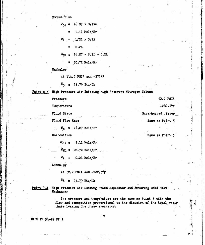
W02 :26.07 x 0.196
u 5.11 Hole/Hr LWA 1/21 XS 5-1.
* 0.24 [WX., * 26.07 - 5.11 - 0.24
I1 20.72 Mols/fr
At 114.7 PSIA and -272op
H5 , 95.79 Btu/Lb
Point 6-N High Pressure Air Entering High Pressure Nitrogen Column
Pressure 52.2 PSIA
T xerature -282.50o
Fluid State Superheated ¥apr
Fluid Flow Rate Same as Point 5
- -W 6 26.07 Kola/Hr 44
Ceoosition Same as Point 5
WO 2 5..1 Xols/Hr
W ~W2 20072 Nola/Hr
WA- 0.24M ola/Hr
Enthalpy
At 52.2 P5A a&ad -282.50F
H6 * 95.79 Btu/Lb
Point 7-N High Preuars Air Leaving Phase Separator and Rate-ing Cold BeatExchanger
"The presunre and temperature are the sawme as Point 5 with theflow and cowmosition proportional to the division of the total varr,phase leaving the phase separator.
1.9 1 T

P~e~eure114.7 PSY"A
Temperature -272o°
Fluid State Saturated Vapor
Fluid Flow Rate
W7 = 0,75 x156.02 !
-"117,U2 Kole/Hr
w0p+-z Total 02 Vapor leaving separator - %Ygen to Oblumn
S~r
W02 -29A4 -511
- 22.93 Xols/IRr
WA 1/21 x 22.93
• 1.09 Mols/lH
11 i7.0-2 - .09 -- 22.93
* Q3.O0 Moi•/Hr
-Enthaipy-4
.t 114.7 PSIA and -2720T
H7 a 95.79 Btu/Lb
Poi nt HIth Presse Air -. tering TI-,r-b - de ....
Stream 7 in passing through the heat exohanger will undergo aslight preswvre drop and rise in te~erature. This wazm-up willincrease the wrander efqiiency.
Pressure 112-P=
Temperature -24Op
Fluid State Speheated Vapor
Fluid Flow Rate Sam as Point 7
We z i17,02 Mols/Hr
Compoitior Same as Point 7
20W" AD %-19 PT I

WC2 22,93 Yols/"r
#112 u93.-00 Mols/Hr
&Uthalpy 1
At 112 PSIA and -240O1F
H18 = 1.04.50 Btuk/Lb 4
Point 9-N Low Preasur@ Air Leaving the Expander and Feeding the Low Presnare Col H.
No flow is derande4e thvu.gh-Point 9 since- the only papote of such Al
a flow is to give advantage t• the low oressure column in so far asoxygen production is ioncerned.
Point 13-N Exniader Exhaust Streaw into Air U±quitier
Pres sure - PSIA
Temperature .-306 .,
Fluid State Saturated Vap"orIAFluid Flow te Saae an Point S
WlO 117.02 MolJ/Hr
6 ame &S ]Ptint a
W02 : 22.93 Mo2a/fir
w93.00 Kola/*, "
- Ai Pe~i#~ 1.09 Nqla/Rr
Po~xt114 A r- t 74eimg Air L±•tfier
?imperatu~rs
WLid State SU.turtd TaWm
Fluid Flow Rate
The flow will be strum 4 aims the produt tako-ot
W11~ 9 16.02-2 x2000/0.86 2gz,
WUi w 149.10 Mo3lt/Hr
UM Th5 % .29 P1 21

Composition
Referring to comositions at Point 14, Point 6 and Point 10.
'ýo2 ' 5. 11 Y6 .72 e 2-293 -0.04
S• 32.72 Role/Hrf1
WN2 20.72'- 7.99 ,93.00 -6.84
"1148.7 Xole/Hr
WA 0.24v'. 0.22 0 1.09 - 0.04
Enthaly -Combination of Points 19 and 10
149.10
point 12-N Air Leaving Air Liquifier and Entering Cold. Heat Exchanger
Pressre .. 19 PSIA
Tewmerature -
All of the latent heat of the liquified air is.taken by this JStream,
(95.79 - 89.72) 156.02/149.10 -- 6.34
6.34 7"*90.97 97.31 Btu/Lb
T1 = -283.60F
Fluid State Superheat ed Vapoor
F.2uid Flow Rate Same as Point 11
=1 149.10 Hole/Hr
Composition Same a3 Point 11
W0 2 32.72 Xole/Hr
VpN2 1l14.87 Nola/Hr
VA 1.51 !4cls/Hr
VJADTR 54-19 IT2.

Enthalpy
At 19-PSIA and -2,3.6- . the enthal.,y is L
H12 u97.31 VIM/LFaint 13-9 Waste Air Ltaving Warm Heat Exchanger [
£'re u~re14.7 PSIA"Temerature 720"Fluid State Suoezheated Vapor
Fluid Flow Rate Saze as Point 12Swj3= 14b9.1OY~olu/HT- -. ~ 1
Compouition Same as Point 12
,W02 32.72 Hole/Hr
Woj - 1148.?7 Kole/Hr
'1.5A Mol/Hr
L-11 haloy
At 14.7 PSIA •nd 720F
H1 3 182.97 Btu/Lb
Point ;A-N High Pressure Liquid Leaving Phase 3enarator
-Pre&ze 1..7 •!PSIA.Tenperature -275.60y
Fluid State Saturated Liquid
Fluid 7lw Rate
w 4 * o.0o29 x 156.02
C~offation
WAX T 5h419PT I
U{

i
W"A 0..2 Mol,/Hr
WN2 1 2.q3 -0,22 -4,72
W4•. 7.99 Mole/Hr
Znthalp7
At 114.7 PSTA a.nd -275.611F
22.-55 Btu/Lb
Point ,•-N Low Pressure Air Leaving Zpnsion Valve and Entering Low PressureColum
The licgid air is exkanded to the presure at the top of the -loworessure column at consta~n eatl•la1y.
Pressure 21. PSIA
Temperature,' -304.3"?
Fluid State
The exranuion of saturated liquid from 114.7 PSIA to 21 PSIAremas t n n
- $QLiquid
20.95% Vapor
Fluid Flow Rate Same as Point 14
15 1 12.93 Xols/Hr
Composition
W02 4.72 Mols/Hr1. 7.99 Kole/Hr
WA -0,22
At 21 PSIA and -304.3*'p
H15 22.55 Btu/Lb
I2LIr. t 5-1 T 1

Point 16 Liquid Air : ýsving High Preasure Column
This is the result of liquification of Stream 6 minus the producttake-off.
SPressure 52.2 PSIA F?Toaeraturp -291.90F
Fluid State Saturated Liqid
Fluid Flow Rate
W16 z- 26.07 - 6.1 P 19.15 Mole/Hr
Composition
'wd 5.11- 0.005 x ?000 x 5,07 MoIal/I,
!N2- 20.72 - 6.84
VA 0.24 - 0.04 .020,. _ .
At 52.7 PSIA and -291.90-HI6 = 12.77 Btu/Lb .!
mPoint 17 Liquid Air Entering Low Pressure Colunm
Pressure 21PSA :1
Temperature -304.3*,
Fluid StAte Liquid and Vapor,
The expaion of 52.2 PSIA saturated Ulquid to 21. PSIA
results in 90.40% liquid and 9.60% vapor.
Fluid Picw Rate Sean as Point 16
W1 19.15 Kols/HrC omposition S-ea as Point 16
2W0x2 , 5.07 Mols/lHr
SWA 0.20 (ols/HLr
&2
WA~~~ !!T 4-9F

Enthalpy
At 21 PJAIA and -304 i3 "F
H17 = 12,77 Btu/Lb
Point 18 Waste Air Leaving Low Preggure Column
The wvste air laaving the low oressure column will be saturatedvapor at the pressure at the top of the column,
Pressure 21.5 PSXA
Temperature - 304.oF
Fluid State Saturated Yapor
Fluid Flow Rate
Strew 18 equals stream 19 which equ&ls stream 4 •nirs stream
-10 minms the product tAke-off
Wle 156.02 - 117.02 - 2 x00 x 124 28 0.84 (Due to Droduct flash)
W18 3P.OP Mols/Hr
Cmwosation
W02 = 5.07+ .4.72 - 9,79 Xols,/}Hr
:WN 7.991388 * 21.87 Xols/Hr
WA z 0.22 0.20 B 0.42 Mols/H
At 2-1 PSIA and -.304.30F
-s18 91.10 Btu/Lb
SPoint 19- W~ste Air Leaving Subcooler (Sams as PciiA 18)
Pressure 21 PSIA
Teperature -304.3or
26TAX ~R 54-19 Pf I
SI

•I.•
Fluid State Saturated 7apor F
Fluid Flow Rae Same as Point 18 [W19 = 32.09 Mols!/Hr
Composition Same as Point 18
9.79 Xol/,Hr
WN2 21.87 Ko:A/HrWA -- 0.42 Mol/Hr
gnthalpy
As shown
Hlg 91.10 Btu/Lb
Point 20 Liquid Nitrogen Entering Subcooler
Pressure 52.2 PSIA
T•emrature -2980 F
Fluid State Saturated Liquid
Fluid Flow Rate
'd -z--Zx 2Q00-24 0.86 x 28
W•O - 6.92 HolsiR/H
C,0=ouitionW-2i: 6.,2x 0.99 * 6.84 Xo.s/Hir ]
W0 0.04 Xmlsa/Hr
WA. =-0.04 Hols/Mr
, It it assuxed that the ijmmrty i s equally d.ivld ed be•wtween mygen and argon.
Enthalpy
At 52.2 PSIA and -298OF 4
R20- 12.02 Btu/Lb
U D127=

Point 21-N Liqaid Nitrogen Tako-OCf
Pressure 14.7 PSIA
Te~.ratt.*re _iO7 IFluid State 4 ViDo4
06% LiquiddFluid Flo PMtn
, • W21%. 6.92 Hola/Hz
SCmoinastior
SN2 :6.84 Kola/Hr
0.9 VoIOLr
I
Liquid Q
5.95 Mols/Hv
-I
- t
At 14.7 PSIA and .2980,
H 12.02 ftu/Lb
WAX 5
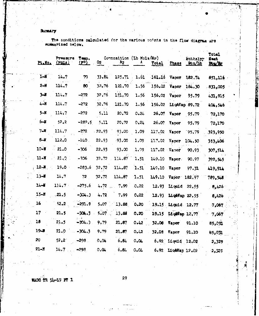
The conditions a1aulated for the various anonts in the flow diagrea ara
Preaw-re TM p. Commosition (Lb Mola/r) . , 9"tP t x-O (1IA) (r~) 02 N2 A Total Phase -B
1-N 14.7 70 33.84 1.29.71 1.61 161.16 Vapor 1.82.74 "It 116
*2-N 114.7 80 32-.76 121.70 1.56 3.56.02 Vapor 184.30 831,005
3-M U14.7 -M7 32.16 2.m.7o 1.56 156.02 Vapor 95.79 431,913
4-M 114.7 -272 32.76, 121.70 1.56 156.02 LiqAVap 89.72 404,546
S5-W• 114.7 -"72 5.11 20.72 0.24 26.07 Vapor 95.79 72,170
6-9 52.2 -2v. 5 5.011 20.72 0.24 26.07 Vavor 95.79 72,170
7..W 114.7 -M72 .2.93 93.00 1.09 117.02 Vapor 95,.79 3•3,950
81 112.0 -240 22.93 93.00 1.09 117.02 Vapor 104.50 353,406
104V 21.0 -306 22.93 93.00 1.09 117.02 Varoor 90.93 307,514
211 -2.-0 -306 32 -72 11.7 1.51 140.10 Vapor- 90.97 39,545'
12-W 19.0 .23632.72 11L.87 1.51 149.10 Vapor 97.31 "192,914
13-4 14.7 72 32.72 .14.87 1.51 149.10 Vapor 182.9 ' 7e9,5,
1I" D14.7 -275.6 4.72 -7.99 0.22 12.93 Liquid 22.55
15-4 21.5 -304.3 4.72 7.99 0.2 12.93 L4q&Vap, 22.55 S,,6
S16 52,2 -M29.9 5,07 .3.88 0.20 19.15 Liquid 12,77 7,067
1.7 21.5 -3%4.3 5.07 13.88 0,20 19.15 Ltq6ap "'177 T 7,067""1 8 21.5•i ' r3 9.79 21.87 0.42 32.00 Vapor 91.10 85,031
19-N 21.0 -304.3 9.79 21.87 0.42 32.0" Vapor 91.10 85,0312-0 5,2 -298 0,04 6.84 0.04 6.92 Liquid 12.02 2,329
21-l l4.w7 -7" 0.04 6.84 0.04 6,92 UIqAap 12,0Cr 2,32
29ii

H~eat Balance
For any~ hett balanre. Qj q,,t where Q W(Lb3/Hr)x H'k~tu/Lb)
Q2 + Q7 +- Q12 iherer Q is corrected to allow for the loss &0e torev &Ig
. 831,005 + 323j950 + 419,914
-1,574,p89
Q+u "-3I"+Q
: 1,574,869
Air LiQu.fier Balancee
Oin 'Z +3• Q11" +-
"4 31,915 4.392,545
62~Ž4 ,460
= 824,4+60
i I4
dia Mt: Q5 Q7 ֥14
72s170 + 323,950 4- 8,426
404,546
WAX m %-19P T 3I o
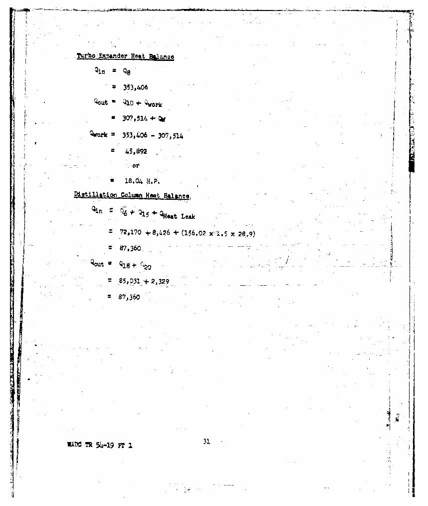
Turto Exwader Hmt kwanaa
S353,406
a 30Y7 514 4-
- w-*~ 353p406 - 30?51R4
1 ]8.04 H.P.
Disti11atio-n Colomn Heat rUlanc.
=72,170 + 80426 +* U56.02 X:1.5 x 28.9)
87o360.
1.ý o5,P31 + 2,32 9
IWAM TR5tv-19 PTI

ov 1 Leal it Balance
Liqu~id Oxnem Prod'uction
100 Le at79 Lb. N2 Aigon (21-x) Lb. 02100 SIG-WOF-1 P310, 7207Airi
(Ref.~~R~rge~*o Pag R2 eaao R rta
(Rket. Patm 12)
(Raf. Page 12) 1x Lbs atl 4. 7 A
HO Intha2.py
-iuis8 Li qui d Oxygeni Generator Heat Balanas
Zntna1Fyr of the Liquid 02 lzeH
U- At the .cbh=ton -2 14.7 thAan 28c Ae entha1ny of the liquid. 02 is
H0 is 489 Btu/Lb_ _
por X Lus. drained
_- - __Enthalpy of the kfflueittWaste Air, AW-
At the conditions of I. FS10 and '720? the entha41~r of the waste air-is equalto the s=. of the entha1pists of the constituents.
The enthalpy Of nitrogern at these conditions is
RNW 183.5 ftu/Lb
All of the nitropn~ contained in th'ýe In; Q;e. air will be waate thus -
Rw1 M8.5 x79 14,4,97 Btu
The entha~lpy of oxygen at these cond~itions is
HOW 181.2 BtU/Lb
WAid n-5h4- pt 1 324

The o•x7ye containidl in the wAste air will be
(21 - x) Lbu/100 Lbs oi Air FeedJ
HOW 1el,2 (21 - x)
- ,805 - 181.2x Btu
H HNWO'OW * I4,497i3,805"- 181.2x
H... 18,)3O2- 181.2x Su,
-ToHal I• w! BlanoA
The total heat balance will be
i•HA f I.5 L HW R 0-X(
* 18,430+150 - 18,302 181.2x3l ,018+8s89x
740 " 172.31.x
- * x 1 4.29 Lbs 02/100 Lb. Air Feed
This indicates i 4.,'9% reoovery by we ght.- For two tons ner day therequiredair intake will be 7
Q 2 Tons x 20 IL&x I Da vx I. Hrs x 1-..u.9.t!x IDays I Ton Hr 6-Mi 0.075 Lb 0,0429
- q • 861 SFMSAeruninit a 3I loss du•rin rewfirsal.
0.03 x 8"3 P5.9
,0Q 863*25.9 889 uay 9 SONt(
Sinoe the panjder requires 750 SOFX and the coopressors are capable of
1000 x 24 x 60 x 0.075 x 0.04291• 2000
Production i 2,32 T/D
0 including Reversal Loss 1030 SUFM
SWADC 7R 34-19 FT I
'A ' M:z
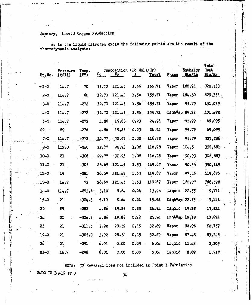
Su aj-y Liquid oxygen~ Production
Ao in the liquid nitrogen cycle the tollowing point; are tho result of thetheor •€iy ic analysis-
SLNO. IA r A Ttg E ,.__b BtgýH.
*1-0 14.7 70 32.70 121.45 1.,56 155.71 Vapor 182.74 822,333 :
2-0 114.7 0 32.70 121.-45 1.56 155.71 Vapor 1.9430 829,35-)-
3-0 11. M-7 32.70 2.21.45 1.56 155.71 Vapor 95,79 -431)0394-0 1.24.7 -2' 32.70 121.45 1.56 155.71 Li4&a 89.22 401,)492
05.0 114.7 -272 4.86 19.85 0.23 24.94 vapor 95.79 69,095
22 89 -276 4.86 19,05 0.23 24.94 Vapor 95.79 69,095 I7-0 124.7 ---- 22.7 92.93 1.-,8 116.78 Vapor 95.79 323,286
.8-0 112.0 --240 22.77 92.93 1.08 116.78 Vapor 104.5 352,62_
10-0 21 -306 ..22.77 92.93 1.08 116.78 Vapor 90.93 3r0688W3
11-0 21 -305 26.69 121.45 1.5"3 149.67 Vapor 90.56 390,649
-- 12-0 - 19 -281 26.69 121.45 1.53 U49.67 Vapor 97.45 419,696
~13-0- 1.7 72 26.69 121.45 2.53 145,-67 Vapor 182.9 788,598
14-o 114.7 -275-.6 5.10 8.64 0.24 13.9i L%. i 22*.5 - 9,11 III
15-0 21 -304.3 5.10 8.64 0.24 13.98 LiW&Vap 22.55 1.11 "
23 89 -282 4.86 19.85 0.23 21.9% Li:gd 19.18 13,92424•3 21 -304 o3 4.96' 19-85 0.23 24.94 U- OVap 19,18 13,02k 4
S .23 21. -311.5 3.92 29. 32 0,#45 32.89 Vapor a6.96 621,757 .
S"19-0 21 -3D5.0 3.92 28.52 0.45 32..69 Vapor 87.4,8 83v248' i
26 21 -291 6.01 0.00 0.03 6.04 U qaid 11. 3 2,209
L21-C 14.7 -298 61C2 0.QO 0.03 6.04 Licqaid e.89 1,712
IN 3T % ev R as•i LoIs not included in Point 1 TaUbtation
M 54c 1 34 I

Oassou@ Nitrogen Production
Incoming Air Waste Air100 Lbs at (7&-x) Lbes N2 , 22 Lbs 02 & Argon100 PSIO, 0O~r 1 PSIO 7/207HA a Enthl't~ y Air Rlw Z nthal!py(Ref. Page 12) Separator
PU_ Int = Hp,. ... Refrigeration RC (Ref. Page 12)
Heat Leak H.L. Iitrogen Prduot
(Ref. Page 1.2) X Lbs e 4~7PI
Figure 9 Gaseoum Nitrogen Heat Balance
MIthalpy of the LiudN2 Pupd,
At the condition of' !4014#7 SIa the entkalpy of the pumped. nitrogen is
F-~ Hy 2.02 3tU/Lb
For x Lbs pumped
HN - 12.02x Btu
Enth&lW of the Effluent Waste Air, " "
At the oonditiona of I PSIG and 7207 the enthalpy of the wpste air is equalto the sun of the enthalpies of the constiunts.
F= HW.B13.5 Btu/L
The nitrogen aofitalned ia the waste air will be (78 - x) Lb/100 Lbs of
Air Feed thus
= 14,313 - 183.5x~i
The enthIlpy of oxygen at these conditions if
HOW sz. rtu/Lb
AD•TR 514-.19 F I

All of 'Uhe "xygen contained in the intake a&Lr Will be waste hence
HOW 181.2 x22
= 3,986 Btu
PV HNW4 H W 14,313 -183.5x 3,986
H. 18,299 - i83.5x
SPump, Inout
It is estimated that the rsm• input to the circuit is 2rH.P. or
2 (HP) x2544 (Btu) 1 Hrs 30 ,o53 Btu/Lv3l-N2
-- Since there are to be x Lbs-of nitrogen med Oea 100 Lbs of &Ur feed
{, ?.,Total .. Heat• Ba•,lance
%He total heat balance will be .. ...... _
LHA~a H.L. 4 P x Rd+ R+ R
-1,9.30 +4210 + 30.53x z 18,299 - 183.5x 4' 1,018 + 12.02x
18,500 + 30.53x * 19,317 - 171.4ax
1902C. ox : 737
S-3.65 Lbs 12/100 Lbs Air Foed
This indicates a 3.65% re4overy by wedght. For two tons per day the"required air intake will be
Q 2 Tons x- It Lb .1D xI Hrxx ~I tx 1S= 10T5 x0~
Dy 1 Ton 2.4 n?" 6F jU.f 0.0751 L 0.-03$65
Since 1% is as•amed to be Reversal Loss
0.03 x 1•5 = 30
STotal Air R-quirsd 1045 SC.P.M.
V ~36
. 51

SSuaryt 0aseous Witrcger, Production
As in the liq•uid nitrogen cycle the following 'oints are the result of the. he 'mo¢yna.o analysisi
Tubal
Pressure Tm. COmoouition (Lb Mole/Rr) Enthalpy HeatPt.Ro OpSI.) 'M2 A Total Phase Btu/Lb Dtu/R- -L
41-PR 34.7 70 33.19 123.27 1.58 158o04 Vapor 182.74 859,355* 2-PN 114.7 80 33.19 123.27 1:58 158.04 VZwor 184.30 S41,764
I-PN 114,7 -272 33.19 123.27 1.58 158.04 Vapor, 95.82 437,624
4-PN 11•.7 -272 33-19 123.27 1.58 158.04 LUq&•,a 89.14 407,123
5-, - 114.7 -272 4.86 19.99 0.23 25.08 Vapor 95.82 69,4516-PH 52.2 -282., 4.86 19.99 0.23 25.08 Vap"o5r,2 655-1-7-PN 114.7 -272 22-.05 94.38 1.10 118,53 V5.or 95.82 3?8,268
I " 8--PW 112.0 -240 23.05 94,3t8 1.10 118.53 Vapor 104.56 358,183
10-PN 21.0 -307 23.05 94.38 1i10 118i53 Vator 90.80 311,070
11-PR 21.0 -306 33.16 117.3. 1.55 252.09 Vapor 90.96 399,•804-•L12-Z• 19.0 -280 33.16 117.38 1.55 19,2.09 Vapor 97-90- 43O30,5
1.3-4N 14.7 72 33.16 117.38 1.55 152.09 Vapor 185'.04 804,55
14-P• 2.7 -275.6 5.27 8.91 0.25 14.-43 Liquid 22.55 9,40415-PN 21.0 -304.3 5.27 8.91 0.25 14.43 Liq&Vap 22.55 9,40427 21,0 -304.3 5.27 9.91 0.25 14.43 Liq&Vap 34.75 14,492
1, I-PR 52.2 -291.9 4.83 14.10 0.20 19.13 L qui d 12.77 7,06017-PR 21.0 -304.3 4.83 14.10 0.20 19.13 Liq&Vap 12277 7,060
1$8-PH 21.0 -304.3 1(i'0 23.01 0.45 33.56 Vai)or 91.49 828,73420-PH 114.7 -298 0.03 5.89 0.03 5.95 Liquid 12.02 2,06029 114.7 -298 0.03 5;.4 0.03 5.95 Liquid 12.02 2,060
30 4014.7 -298 0.03 5.89 0.03 5.95 Vapor 12.02 2,060
" NOTEt 3 Reversal Loai not included in Point 1 Tabulation
WtAX, TPR 54-19 T I2.

r- rall. Heat -Alnnce
Gaseous O7•ypen Prcdu~otion
Air Intake 'daste Air
10 Lbs at 79 Lbs N2 , (21-x) Lba Op100 PSIG, 80OF Air 1 PSI, 72)FHA • ; Enthalpy - t(Ref. Page 12) , Ssenator H Entha1Dy
Pump 1n•r•tHp a Refrigeration RsRef. Page 3). (Ref. Page 12)
Heat Leak • H.L. Oxygen Prohict' :('Ref ', Page 12)LL -R a 1x Lbs at 4014.7 PSIA
H O- Enthalpy
o Figure 10 Gaseous xcygen Heat Balance
S~~~Enthalpoy of the Liquid D• •,eH
SAt the c ndition of 4014.7 PSIA the enthalpy of the umimed liquid in
Le 89 6tu/Lb
For x Lbs. mped -
HO= 8,89x Btu
Inthalry of the Efi'luent Waste Air, HW •At the conditions of 720F and 1 PSIG the enthalpy of the effluent waste air
r-Vthay o the sumoef t Rholies of the constituents.
The enthalpy of nitrogen under these conditions is
SHy . 183.5 Btu/Lb
All of the nitrogen oontained in the intake air will be waste thus
H m- 183.5 x 79 = 14,497 Btu
The enthulpy of oxygen under these conditions is
181. Pe. Btu/Lb
WADC h ~4-9 38

The rxygen contained in the waste air will be
L b. z- L) il. b. :f ,it r d h,! n me
HN~ 161.2 (21 - X)
S3,805 - 161.2
HW HNW +4lP7 4- 3,8ý -181.2x
HW 18,302 - 181.2x Btu
Total Heat Balance
The total heat bslance will be
HA H.L-+ HP= Hw + R •H0
-18,030+ 150 + 30.53x 18,302 - 181.2x -1,018 8.89x
740 203.74x
x : 3.63 Lbe O2/100 Lbs Air Feed or a 3.63% by weight recover.-
The rpquired air initake for two tons per day will beS2 Ton s x 2000 Lbe x I av x 1 rs x Cu-Ft x 1
D fay I Ton 24Hr 60 E- -0.0~75 Lb 0.0363
- 1020 SCFXr-
Ausuming 3% Losa upon Reversal
1050 SCOA
L
3?WAD-iTh 54-19 PT
.1

Summary: Gaseous Oz7t Nrcduý,tiý.r.
As in the liquid tltrogen cycle the following points are the result of the
themodynamin analysisi
TotalP~rem~ure Tem. Com~ovition jLb Mole4Hr) Enthj-1ý7 Hoaý
Pt, No i'PSAL 22. 0'I T- otl U Iase B-tU,. lo~
• -Y0 14.7 70 33.35 123.88 1.59 15.82, Vapor 2.-2,74 838,758
2-PO L.4.7 80 '13.35 123.88 1.59 158.82 Varor 184.30 845,918
3-MO 114.7 -272 33.35 123.88 1.59 158.82 Vapor 95.79 439,666
4-4O 114.7 -272 33,35 123.88 1.59 158.82 Lioq&Vap 88.11 404,433
5-PO 114.7 -272 .43 1S.40 0.21 23.04 Varnr 95.79 63,782
2,2-PO 89 -276 L.43 18.40 0.21 23,04 Varor 95.79 63,782
7-PO 114.7 -272 22,89 95.14 1.09 119.12 Vanor 95.79 3291764
8-PO .12 -24o0 22.89 95.14 1.09 119.12 Vapor 104.50 359,748
20-"- 21 -306 22.89 95.-1 1.09 119.12 Vapor 90.93 313,033
11-PC 21 -305 28.17 123.88 1.56 153.61 VApar 90.02 398,193
12-PO 21 -281 28.17 123. 8 1.56 151.-*i Vapor 97. va 433,426
13-PO 14.7 72 28.17 123.88 1.56 153.61 Vacor 182.97 809,694
14 -.-P0 114.7 -275.6 6.03 10.34 0.29 16.66 Liquid 22.55 10,887
S15-PO 21 -304.3 6.03 10.34 0.29 16.66 Liq&Va: 22.55 10,887
2 8 21 -304.3 6.03 10.34 0.29 16.66 Liq&VaP 33.11 15,942
S23-P0 89 -282 4.43 18.40 0.21 23.04 Liquid 19.18 12,771
S24-PO 21 -304.3 4.43 18.40 0.21 23,04 Liq&Var 19.18 12,771
C2-PO 21 -31I.5 5.28 8.714 0.47 34,49 Varor 87.71 84,703
19-PO 21 -305 5.28 28.74 0.47 34.49 Vaoor 88.14 85,127
- 2", PO 21 -291 5.18 0.00 0.03 5.21 Liquid 11.43 i,9
31 21 -298 5.18 0.00 0.03 5.21 Liquid 8.89 1,482
32 4014.7 -298 5.18 0.00 0,03 5.21 Vanor 8.89 1,482
NOTE': 3% Revergal Loss not included in Point 1 Tabulation
vWY;71% T I401WAD!;T -9P

-, '4
General
The e-quinzmtrt s .eciof•,i+,on e l ad b r.i. •- _ -'.nsidered t• " thorecuirements of the liquid oxygen, nitrcoen generator from the viewpoints ofperformarnce, mize, and weight. However, they shall be subject to nossille chang6sresulting from iinal design considerations as well as availability of mater.ials.
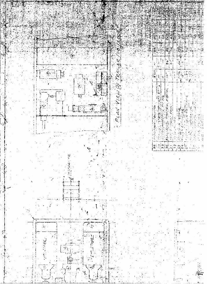
The layout of the equ!ipnent comornents within a semitrailer is illuetstated inFigure 12.
S-nitrailer,- The semitrailer shall be a Fruehauf semitrailer. It shall beconstructed so that it is &dentable for towing by a standard ArMy trucktractor, R-nd shn~l withstand the strains of service encountered when
towed across the country with full equnrnent. The unit shql! not exceedthe following dimensions:
Height, 12 ft. 0 in.Width: 9 ft. 6 in..Length: 32 ft. 0 in.
The total weight of the semitrailer and e-uicient shall be atroximtatly45,756 nounds, of which 16,L.5ly 6 0 oounds shell rerresent theweight of the seritra•ler. The semAtr;tler shall nermit a clear sweoepof 70 inches hehind the king vin for full turning. A standard SAE kingnin sha2-. te nrovided and shall be located an;roxlmately 22 •rches backSof the trailer front edgp to nernit the swinging of the treiler corner
Sthrough a cleAr srace of 62 inches. The trailer fifth wheel nlnte shallbe of sufficient size to Uit a 36•-nch diameter fifth whetl on the trucktractor and snall he 53 inches from. a level ground surface when thetrailer floor is l.vel.
WTheels -The wheels, studs'and can nuts shal. conforn to a:lic0hle Gov-4 em.inent snecifications.
Wheel Hubs -The wheel hubs shall he fitted with tarered rolior bearingsS•of ad.sq•ate size for thxý required sceeds and loads. Bearings shall•]<iconform. to SAE standards.
Tires - Tires shall be of the heaey u•t-y, truck-and-bus, balcoi type, withSnondirmctioral 7ud-and-snow type trmad.
Tubes - Tubes shall be of thi heavy duty tv"•e.
44WAMC R 4-19 FT I

L- J
I It
4i)1 4 )
L 'AL
F *1! ~ 4 <jj
LLAL'4- 5 ~
K' 7 F Cs 'Qt t;JYllji45j2 t�J'4'�
�{tj�'Yr "''
K' �' rt'i � � � � V4t7*f�
t vS
y¶'� t '1 � � A V � 4% <K; F' ,�
-� � 4�%t�' �W'pAr�
� _ 4&F2�p4;I�r*>�:7* �� 1 � t$j � Jt�4I'i 7 lyL�YLs
'CV' I
:7 <4 -� '4� - � '4 � 1
2'' 4½
�
- �"4t�
I � '- I L 1 4 1 Pf
I �L
1 4 1'> �, A'4
t � '� tv'
-I
j"'�r I
H I 114 V
4,
, P
½"'7
't� �
r;} ' p4 4. 'U L� j'i-2v
Lb �11 t I ' - K
I '
2'
K
'Ni5
q' i�I,
- 4 q I' �K F�n� t� a.
Kt
""
1 a,
IF
V ''� t
I I$
��r---;-x-t, LI I 211L.t S;7 /.
-4 1
'-I.
�-' -It.. -
y'c �'' K \t/NJ�
Ill 1 _________u- ______ __ -'___________ ____ IL -

.---- �--� L� 44 a.. d�C awl ---. 44t�.
r .--.--. �..----.---------
'a 4'
� 'I'I Ca Cl ,, � �KC�J 3 � � r
V I "--'I, �titrL 3� 1 .,.C �
CC,' r �NI
% *9
I ,�- . 4 j!�IAJ ; ml r-'
2,
�' K
4�. 1kV . NA NII K
� '4
r '4�4' I'. b4
V (4:, . .i"'U
Ct" V . II] l� -- '�.>ti - �
- - ''.: C2' �4.
7
A .
**1' '4
14
Ii./ A,
- '�- +
-1 1-
4 t
2I,
- 1p 4-
. .
Il II- '
psi-- I �j, C...1 -. Ct
2j q. I . '-(--VIL I) .9
I �,4' I
- L�u \;T'/ 4
I�m�m.flrnhumiaafluucassbflfl�u maaaniasva�saameP

I.
- I-�.
t
-I
1: -,-- I
/ *-1- --

pi>
t477r 4
I0, 4 J5.J P' A v~i.kXt
<'" vjkrA'4'41] & ~ v~y tt ' ~ . V'4~s tzivrit ;~ I.1410
~~rj ,Jr~~ ~~?;c' k4;¼p"& 42>¶a. ~ ,S
L L,
K j7
:1Brakes
Service Frakes - Service brakes, controllable from the driver's seat of thet.;wing vehi,:e, shall be rrovided. The drums shall have flanges orribbin" to prevent oD.jectionable distortion when the brakes are arl.id.The brakes shall be of the internal mexanding, two shoe, heavy-duty type,having co'nt.ft ,! ft cams and rigid brake-shoe anchors, and shall beoperated through fUlly enclosed vow -gtr ýype slack adjsterx, Brakes,ýLnehors, and c2amt shall have suitAble lubricAtion fittings.
Service Brake Controls (Air) - AX1 detail parts and assemblies of the brakecontrol system shall be equal to &nd interchangeable vith the equipmentmanuractured by The Bendix Westinghouse Autotiv% Air Brake Comoeny,ESlyrla, Ohio, and shall b-i Installed in accordance with the mamfacturer'slatest reacommendativrs, The controls shall be trovided with stndarsemergency break-away features. The bre':-away arrangment shall Conformto re'quirements of The Interstate Ciuuerce Cormission. The controisshall be sealed in a manner that wUl emsire satisfactory operation inall k6ndz of ý-it.her. -- All chambe~rv shall be provided with drain, on thenon-pressure side.- Air hose conn.ctinrns ire ftittngs shall be of thererplaeable type with spriný prYree~ors. Air line fti•erv briailprovided in both emergenoy and servize lines. A relay emergency exhoustchock valva and hetvy.4uty clamoing studs shall be furnished. Theet•ndr rd air,.brake coa"plingi shall be 'oilded for connecting the brnkelines tn the towing vihicle. A dmaq couling shall be attached with a
-Lcain t,• each of the air hose couplings. Two detachable air ho .ines
-- of rupr length and equipped with standArd air hose couplings, shall be-vp,)3led for connecting the brake system to the towing vehicle. Whendetache-•. the hose lines, with electricaJ. connectin- ¢•lea shall becarpied on the generating nlant.
Parking Brakes - In t.adition to the air-brahe meohhnism, a ratchet-and-pawlf / type mechanism, or equivalent, shall be ýrovided for opernting and settingthe brakes by haed. This brake shall be capable -,A skidding the wheelsundj P11 load cn a dry, level, concrete rAvement. The Da/rking brakes1- shltl ,neated by a crank or lever plAced in a suitable, zrcteotedp•osition on the right hand side or rear of the vehicle. No partt of thebrake mechanism shall be a factcr limiting the travel clearance,
Landing G•Cir - The landin6 gear shall be of r,3ed construction, shall be "jmanuallF onerat e-6, ir ahAll be so designed that the wheels may be ands-pendesitl7 onerated tc serve as leveling Jacks. The laxiding gear shallbe p:,oyidel with a locking mtnh~anism to lock the landing gear in any
S...... "-pooetica, Two, built-in, screw-tFN~ leveling lacks shall be providerd Atthe rep.r or thn, trailer. The Jacks shall, be d[irt-jr-oof and •etlf -aligning.,
Suitable Atck planks shall be furnished, conveniently mounted under thetrai er.
Body - The Indy shal:L be nf van-type with door and/or winow .ienings designedto affori the most efficient operating conditionr. The roof shKl2 becrowned .or dralilage p.irooees, and shall be made in removable uectione orprovided with renovable hatchea to permit reoval and replacoemt ofequiIment cotmonunts within the van. The roofing material shall havesufficie rr' strength to suzuort %• O0 pound man walking thereon. Smitablehe-ay-duty driz zOudLing halil be rrovided around the entire roof.
I1)DC TR 54-l') FL 2.

Floor - The sewirtrailer floor shsll be adequats for the equl-r.ent loads andoperating conditivna. When an all metal floc" ie Provided, 4.t shall bmcoated with a suitable non-s'4d, pliastic material. When a wood floor isprovided, the wood for the floor shall be either manle or bit'oh, secondgrade, in accordance wIth the National Kavle Flooring F-umfaeturer'sAssooiaticn Grading Rules, or oak, oelnb grada, in accorlanre with theNational Oak Flooring Manufaeturerls Association Or~ding Rules. WoodfTninjv ihial be not 1,2e than Ij inches thick and shall be surfacedtwo sides and tonue-and-groove. notra shall b- chemically treated toreteol insects. Flooring shall run lengthwise of the trailer and shallbe securely fastened to ewch cross member by means of galvanized wmodscrews with heads countersun1 to be flush wtth the floor, The floar shallbe sealed at all points with pitch or other suitable sealing comound.,
Doors and/or Windows - Doors, removable panels or hatches shall be providedon the sewitrailor as required for accverience of oneration, aacessibilityof rlant commonents, and to facklitate reemoval of equirm.ent for repairand maintenance. Windows shall he irtealled in the van-tyv-p body of theseertrailer as required. Windows shall bc glazed with shatterproof glass.,
Steos - Dmo~untable-tyne stevs 9hall be rtcvide4 for use at the doors. Ste"sshall be Drovided with suitable grab h`ndlss and non-slip tread plates,and shnll be ea~sily attached and detached at the sill. Proviksion shallbe made for stcwing steps inside the demitrailer when not in use,
Wiring - The vehicle ,hall be wired for an electrical iuoply of 24 voltsdirect current. Cable used for wiring shall be eceased in fleible non-metallic tubing, Terminal lugs shall be soldered to t~e wire ends,Junction blocks shall have bAses made of thermosetting, laminated,phenol-formaldehyde plastic, or other equally suitable material, and shallbe equipped with suitAble studs, washer?--and nuts for the attcshment Ofterminal lugs. The circuits shalI be oolor or number trac.d, Suitablegrommets, or clamms, to nrevent chafing of cable, shall bo furhished wherewire pacees through structural members. A receptacle with hinged cover,to allow the running lights of the semitrailer to be controlled from thedri.ver's seat of the towing vehicle, shall be recessed in the frame. Atable to connect the trailer to the towine vehicle shall be :rovided.
lamps and Reflector Assemblies - All lanps shall be readily acoessa.ble for thechanging of bulbs and lenses, and for makinR rep~ir5. The s9,,or a.d taillamps shall be recessed anproxmmately j inch from the surfacs of the
Sframe mmber. The following lames and reflectors shall be rrovidod onthe vehicle, located to conform to Interstate Comerce Co..ssion MotorCarrier Safety Regulationsu
Refleat Reflector (Red and Amber),4 Recettacle and Hinged Cover Assembly
H.i. Tail Lamp Aqsembly, 24 Volt$ L.H. Tail Lamp Assembly, 24 Volt
Clearance Lamp Assembly, 24 Volt
"So--trqiler Insulation - The semitrailer operating space shall be insulatedwith muitable inwalating material such as mineral fiber bonded togetherwith a thmrmoeetting olasti c resin to form a resilient, serii-rigid,dtmansionally stable insulation, sealed in Dlnce against moisture"•' ~~I.nf fitrati•on .,•
WADý R 54ý9 PTI

Electrical Equipm~ent A 3u'.tatle numb-ir of domo lights qqth n4 cfissry wir~(ng
and switches, ;,nd 4!,th bulbq of ep..ffcient cand~lepow~ir shall be installed
to rrov~Ie actet.-ate light, fr onerVtinfr, tMR ý-ulr~qent at r.lnht. A sult-Ificient number o. convenienca outlets shall be pmridei for trerwgfrw.ydrorlight cords. An emairge-noy auixi.Aiar, 1lkg)hoing sysate sunolied byrower from tne 24 volt diesel engine starting battery bank shall be nrovided.
Constru~tion Design 1Yethods - All construct 'ion design imithoda and materialsfor al.l oarts of the %writ "hall be selected for the lightest tosm~ble enditem wetthm't sacrifice of dependability and strength.
Lubrioation -All woving Dartz shi~ll be prolzid-sd with suttabl.e means oflubrication,
Lubrioants - All movina parta shall be designed to ozar&te efficiently andsatisfactoril1e when 1l'bricatted with standa~rd Armed P..rces lubricants.
Grease Fitt'IJgs - Grease fittings shall be located in accessible, protected'positions, A b~right rod circel shall be painted around each, lubr~.cat-iigioeinte
Caution Plates - Where the u~se of high-nressure lubricatin~g equirmentl. 1,000P31 or higher, will damage 7renae, sseals or other "tst, a suitable WArningshall h-e affixmd to the eqi{rvent in a rorcuu locetion,
Fungus Control? . The semitrailer shall be tre~ttid to resist the growth ofIu[KLifting Attac~nents -The asuitrniler shAll be prorided with suittible lifting
attachv'entA to enable the trailer,, with all. equipment installed in iti, tobe lifted in its normal position. The-11ft~ing- attqchment shAll hAva arltniim= ontety rfactor of fi1ve btsed on tll-lttmate stren~th of tho Materi-al. The eye of each l'ftitig att1 ochrrent shall be not less than three nobesin diameter.
kauatue' Identirication - The semitraller shal:, bear the na~ifactura3rlsname and/or tr~demarý ýz:, a rssv'l rnhte securc'ly affixed 113 a consrli.ýIot;
#1 place. In l±ie or' the name r'late, the manufacturerla identification 317be cast Integral with, stamped, or otherwise penianently marked uoon thecomoonents of the equipment,
Instraction Plnktes -The seetitrM~iir, when applicable, shall be equirped Withinstruction plates, suitably located, describing any special or importantpr~ocelu.rn to bm f',ll~owed in overatin; "nd servi~in thi aquim, ent.
Treatment, Pminting, and Stenciling -All ;arts of the aamitrsiler body anid60V running gear mhall be, troiated ond painted to resiat the (f f ects of sand,
dust, humidity and moist salt &'-r,
Stenciling - The cross weight of the seaitrailer with !ýl U ~ n installedin it shall be stenciled or eakch side o2ý the semitra._lez in sauch manner asto bi readily discernible to mil.itary pe?"Eonnal. The pi-escribed tire
Ipressure shl estenciled on -the frame )r body of the unitý in a positionnear the wheels, using block- or stenoil-typs letters not more than oneinch high.
MD T 51- 9 P 45

AIR FILT'rR
The air filter etlement shall be a Dol- inger Corporation atayvwv YodelI&E-L, dry panel ty-pa air fil.ter, com.Dtts with cael. frame and insert. Thefiltwring medium shall bc, bonded glasts. Twcý elements shall be reqmire4. Theyshall be r"munted in A 2.ig~hteight steel. duct*
Nomnal Filter ElementSize, Ins.
Height 20Width 25Thickness 4
Normal CapacityAir Volume, CM 75Air Velocity,, FPX
Air Volume, CFM10
Pressure DropA', 7(50 OFX air ouaIn.A'lte0,2At. 1000 CFM Air Volume, Ins. of Water 00
Duct' Size
iAHeight, Ins. -20
7he air compressor shall ossoftrsRaSanrdCprti,"Standard~airem blowers., Fach blower shall be a three lobe, rotary, !:ositive
disl~c~¶ntaxilflow, oiotl ht%.ty, duty blower having helical rotors.
standard cuý$ic i'ast per minute of air shall be compressed trom in~takce conditionsof 1J..7 PSIA and '70OF And discharged as oil-free air tt 114,7 -58IA. Eachblowir shall be equirped with a shaft extension to provide a driv" for an inter-
L ~cooI~ar or Rftp.'roooler fan. This extension shall be ca~able of transmitting aload of 10 horsep~ower to the cocling fan by eC.ther a d:,ract cdrive or throughthe u!le of a V-belt drive*
~¶AWArCM1J--19P 1' I

k j
F-ch stage srall be tested individually in accorcAnce w~th the Americall3ociety of Moohanrical Engineers Power Test Ccle (Fr 9-39). Each stage shallbe guaranteed to be within the Derissible limit of 3% of the snm.eficationslisted below.
Specificat•ions
Is~~tcaiislt Stage 2,p 3tras 3rSt
Blower Model BBl4 7BIO 57BlOSpeed, RPW 2330 2390 3220Intake Pressure, PSIA 14.56 30.4 59.9Discharge Pressure, PSIA 31.4 60.; 115,7Absolute Presrsre Ratio 2.1611 2.0• 1.9311Intake Volume, CFM 1100 556 277Intake Temperatuire, 0 4runine •30 560 560Discharge Teperature, OF 264 302 287Adiabittic Horsepower 60 56.5 52.3Brake Horsepower 102 103 99Overal-I Adiabatic Efficiency, % 59 55 53Direot:.on of Rotation, Viewing Driveshalt
Endclou e Clo1ckwise ClockwiseApprmoximat e Size
Length, In. 45-3/8 41 414idth, In. 26-5/8 24-5/8 20-1/2Height, In. 24-3/4 22-1/2 17-1/4
A;prvodmaate Weight, Lbs. 1227 950 710
- INT"0OLES5 ANJD AFERnOOLZR
Tht, i•tercoolera and nfterccoler shall be Trane Company cooler-s. TheyShall to o4 all aluminum construvtion. The c-ooling air face ,shall measure20-5/1 inches by 32 irchmo, and the cooling air flow length shall .be 10 nches.
•D~~eciti cations
SIst Stage Zid Stage 3d StageCooler Cooler
Duty, Stu/Hr P35,000 270,000 235jC00
Rot Air Side
Flw h/ :4 004,50 4s5D00Inlet Temneratux,,,, o 264 302 287Outlet Teiperature, OF 90 90 90Inlet Fressure, PS31• 16.7 46.7 101.0Pressure Drop, PSI 0.49 0.30 0. S dN S tu./Fr,' 3~.Ft., OF 27.8 27.8 27.8
tmber of Pansages :14 24 24Flow Lngh, In. "3 32Fin 1ýep V/t In. Serrute/ 118 In. Serrated, 1/8 In. Serrated
Fin Iteight x Thicknrws,In. 0.375 x 0.006 0.375 x 0.006 0.375 x 0.00S
$ •/ Sensible heat transfer coefficiet ccrrected for tin effiziency.
M 51 F14

1
let Stage 2nd Stage 3rd StageCooler 0oojsr Cooler
Fir, SDacing, Per In. 12 12 12T'ntnl Surface, Sq.,Ft. %1 541 541Air Inlet Conneotin Size, In. 4 4Air Outlet Connection Sizt, In. 6 4 3Air Blowdown Connection Size, In, 2 1-1/2 1-1/4
Cooling Air SideFlow, Lbs/Hr 13,500 13,500 13,5OOInlet Temperature, OF 80SOutlst Temperature, OF 157.3 l63.1 152.3Pressure Drop, Ins. Water 4.24 4.28 4.224
Number of Passages 25 25 25
Flow Length, Ins. 10 10 10Fin Type Herringbone Hrringbono HerringboneFin Height x Thickness, ins. 0.416 x 0,D06 0.416 x 0.006 0.416 x 0.006F•n Soacing, Per in. 17 17 17Total Surrace, So, Ft. 850 850 850
Approxmate Total Weight, Lbs. 120 120 120
INTER- AND AFTERCOOLER FANS
iThe iner- and aftereoo1er fans s•all be Trans Coany centrifugal fans withthe blades inclined backward to the diiection of rotation. They shall be of singlewidth and _hall h~ve single inlets. They &hall be of lockaeax-tyve construction,with convertible discharge orientation• and with sandsrd steel shafts.
L S8recifications
.st StAge 2 3rd StaAeSFan Model 16 BI SWSI 16 BI S VS 13 BI N(SIFan Size 16 16 13Fan Arrangemant 2 2 2Fan Clags II II
* Wheel Wifth, % 85 83 95Fan epeý,, RPM 23A0 2390 32;0Direction of Rotation Vievirng DriveshAft End Clockwise Clockwise ClockwiseDelivery, CFM 3465 3525 3465Static Pressure, Ins. of Water '. V4 4.28 4.24Brake Moratpower 3.28 3,42 3.69Orientation of Discharge Up Blast Up Blast Up Blast
"•ir Approximate SiztLength, In. 28-3/4 28-3/4 26-1/8Width, In. 31-3/4 31-3/4 26Height, In. 33-3/8 33-3/8 2?-5/8
Approximate Weight, Lbs. 84 86 70
~ ~!49 ~48

4 ~DIESEL ENQINiK
Diesel Fine fnLtrse. Reuiremsntj
In this generator, the blowers and inter- and aftereooler fans of each Atage
d arw direct-driven in tandem by ,,paraLe diesel engines through suitable trans-uluslons. In addition, a 18.7 Kva, 120/208 volt, 3 hasse, 60 Cycle elcetriaalgr'erator is belt driven by the third-st;e diesel engine. The following tableii a aoo lation of the anticipated bra•k horsepower loads on the ird.viduald.esel engines required to drive thege comoonenter
-- 3Stage .... e HorseepwerBlower Transmiesion Intereoclar Electric Total
-Lose -2to 4% .Generato -
:Lot StA~ge 102 3.57 3.28 108.852rd Stage 103 3.60 3.42 110.02
A 3rd StIgs 99 3.46 3.69 11.0 117.15
- The three diesel engines shall be General Motors Corpuration two cycle; 9ixJ • cylinder, radiator-cooled, short base, coon diesel engines, Series 6-71, Model
60300.
ftciictonsEnigine Model Number 3OG
" Engine G( 6-71 PC552-0;role Diesel
Number of Cylinders 6Bore, In. 4-1/4Stroke, In. 5Tot•. Displacement, Cu. Zn. 4 2.6Rated BIW, Basic Engine at 200 RPM 200i~i!Rated M•P, with Standard 3Vipment at 1800 EMI 153
Continuous B", with Standard Equipeent at 1800 RPK 138
C ontinuous BHP, with Standard Eqipment at 1600 RPM 130tMXP, Continuoul Rating at 1800 OMs PSI 71M , Continuous Rating at 1600 RP, PSI 75
Maxtrm Torque, 1000 RPM (60 Cu. NX, Injector), Lb Ft 526
Piston Speed at 1800 RPM, M 1500Piston Speed at 1600 1PM FM 1333U•' preasion Ratio 161lLubrication ?arced Feed"Flywheel Housing Size No.1 SAIMaximum Fuel Pump Lift to Fuel Punp Level, In. 4Heat Abr-'rbrd by Cooli•g Water. (Per P• at Amhient
Temperature of 1100F) Btu/HP,*rn, 35Air Rqquirel for Scavenging ahd Cot•bustion at 1800 RPM, CFK 600-hauat•. Back Pressurt (ýKaximm at anifcId Flange at 1800 RPM), •h. Hg. 4j Lubricating Oil Refil1 Cap-oity, Including Filter(a), Qt. 29CoolinC ter Syst,% Capacity, Gal. 8-3/4
-49WAD CR 5L4-i9q Fr 1

h
Approxim~te SizeLength, In. 61!-13/i6Width, In.itHeight., In. • -/
Approximate Weight; Dry, Lbs. a6,0
Standazcf1 ;-_4i=nt
Rotation - Counterciockvi.e, a -pewLng flywheel end,
"".oltrg System - iieavý duty radiator. 1Ubrli:atr:1LngStI anooler, water outletmanifold, the•motat for tL-peratule control, engine water circul&ating pumpf.fOtiOtn tyce fanM
F F uel System - Primary and secondary fuel filt-ars, 60 cu. am. injectors, fueli, circulating pump.
Lubrication System - Lubricating oil pressure pt oil filter &sep'1y.
*l "Instruments - Instrument Panel Assembly include,: Starter siitcb, £#te•r,lube oil presaure gauge, water temperature gauge, thrcttle control knob,remote control lever and space for accessory air heater controle andtachometer,
Jiascellaneua - Fabricated steel base, hydraulic type govertor with control oninstruzent pAnel, exhaust manifold and companion flange, tools for ordinarymsintenancs, manual for minor maintenance and operating instrnotions.
'QptionaLE2 Eqftent
Electrical - Battery charging generator and voltage regulator assembly (24 volt,600 watt, insulated) starting motor (.4 volt, insulated).
r Miscellaneous - Air irnlet housing for remotely mounted extra c-pecity air cleaner,
Donaldson extra heavy duty oil bath type sir cleaner.
Accssries
Automatic Bell Alarm for high water temoorature and low oil pressure, air heaterand pump for cold weath-r LatArting, i6-inch flaxibie ewaust connection withpipe thread ends, unnounted uf fler for moderate silencing*
* j DIESEL ENaINE T.ANSMSSION
Description
The diesel enginot tr~nsmission shall be a Cotta Transmiiaion Comamny Model•.FAAU-R Tranemission equipped with an SJZ No. 2 bell housing and Rockford singleplate, 14", over-center clutch. It shall be com olete with pilot bearings andoil cirmalating nump. The transmission shall be so designed and construcote,that it is carable of attachment and connection to a ieneral Motors Model 60300Series 6-71 RC• Diesel Engire without modificatioii. The transmission bell
,
WAYn Th 54-19 PT 1

housing shall be fabricated with a olutch operating shaft extending thrmnuh *rdto the outside on both right and left hand didas of tho bell housing to providefor optional location of a clutch operating lever*
ý'Ifications- Unit No. I Unit No, 2 Unit Nu. .I$
le1t -St~rte 2nd Stsge Ii -tt
Horsepower to bo Transmitted, Mlnimu 100 100 IUDIir.it S;-e ýr" (4nnrmAte) 1580 1620 1600Output Speed, M (Appr•x-Amate) 2330 2390 322Overaspeed Ratio 1,47611 1.4761l 2.012Transmission Efficimxny, Per Cent 96 to 98 96 to 98 96 to 9•Tyme of DAtj Continuous Continuous Continuous
SDire;ction of Rotaktion, Viewing Cm~nter- Counter.- Cmunter-
"Output Shaft Clokwiase Cleokwise CloukwiLs,Approximate Si7- 333
Length, In. 34 34 34Width, In. 22 22 22Height, In. 24 24
Approciiuato Weight, Lbs. 630 630 630
DIE1 EZL ZUE START:NG BATTIa
The diesel engine starting battery &ýal1 be a Delco Products Division ofOener-al Motors Corporation Heavy Doty, Model 25A1, Slx-Volt Storage Battery.The battery shall have three lead and acid type cells enclosed in a compouitionrubber zaae. For- of theso batteries shall be connected in series to gerratethe 24, volts nenesmary to stArt the diesel enginls.
Spec if i cati.on m,
Canacity200 A",Itre Hours at 20 Hour Ratirgb 150 Ampere Hours at 4 Hour Ratirg
Delivery Rates50 Am~eres for 175 Minutes at SOF
3C0 Autperes for 11 MJ'utes Pt 00?820 Aniveres for 1.5 Minutes at 06Y
-1060 Amperes for 1.5 Minutes at 3:;P
At the above rAtes the battery shall be depleted to an average of one voltper cell.
Aproimate SizA 1-/Length, In. 16-1/2Width, In. .. 2Height, In. 10
A-pproximate Weight, Lis.
51-•IY r' r- T

DIESEL RqN0INS FUEL 011, SUPPLY TANK
Calcu.toon of S1%e
In acord=noe with the contract, the fuel oupply tank 5hall have 4 ndniwmumcapacity for 11 hours of continuous ooeration for the gentrator at full load.
Specific Fuel Concumptions
Firat-Stage Engine at 108.85 BRP, 1600 RPM 7.14 OPH.Saond-Stage Engine at 110.02 BHP, 1600 RPM 7.23 OPHThir-Stb e £ngine at U7.15 BHý 1600 RMP 7,68 CPRH
Total 22.0) UPH
Camacity Raevired
Vreqfd •22.05 L_0 3 12 (Hrs)
S= •265 Gjam..
Use Vtznk G •?5 Ol
For the trailer which is 9 feet 6 inches wide, a steel, cylindr!-.i fuel tankI 8 feet 10 Inchas leng shall be stra:ped beneath the floor of the air sourcei section.
SV0yI1 77' Di2 (cro'ss sectional area) x Is (length*I +°
AlsoSVCyI a :275 (Ga) x 231. 4
D2 275x. 10
D 27.68 Ine. Use 27.75 InL.i ~ Specif! cations
I Insida Diameter, In. 27.75L Length, In. I06.0
, ' Tn±cknems, In.1/
"Capacity, Gals. 275Weight, D27 , Lbs. 360Weight, Wet, Lbs. 2310
,AtC T. 54-19 P" I2
- 1

AIR COM{PR,33COR CONDENSATE TR4?
De sorit _
The air oompressor oondensato trae sh,0Ll be fabeicated by Air Products,Inaarporatnd. It shall have a tangential side inlet and a bottom outlet. Itshall have a condensate drain connection at the low.et pooit in the bottomhead.
s~egiftce'tioiis
Mat erial SteelShell Length, Ins. 30Shell Diameter, Ins. 10Shell Thickness, Ins. 1/dHead Diameter, Ins. 10h eard Thickness, Ins. 1/8Heed weight, Ins. 4Inlet 0omnettiun Size, Ins. 4Outlet Connection Site, Ins. 4Condoniate Drain Conneotion Size, Ins, 1Xaizui Working Prerctara, PSI3 100ADproximate Weight, Lbs. 50
jSWITCH VALVE
The switch valve shall be manufactured by Air Products, lnooroorated.It shill be a dou., A poppet-typ vAlve having a carbon steel body and stainlesssteel-stem. It shall have two h-inch high pressure air inlet conneotiono|one h waste air outlet conntction; and two 5-inch connections c-smon toboth the high pressure air OUtlet and the waite air inlet. The switch valveshall be actuated by a Logansvort Machine C 4*any, Incoroorated enon-rotating,double-acting air cylinder, Model No. 2l0•. Tho air c4linder shall have a6-inch bore, 4-'inch stroke and 1/2 inch iron pi_'e ci.e air connections. The aircylinder, in turn, shall be controlled by a Be'llws Cocpa"Y four-way solenoidrair valve, Model No. EV-15B Blectroaire Valve, havilg a 115/8 volt transromerand 1/2 inch iron pip* a de ai inlet con-mection. The solenoid valva 3hall Ieair pjerr4 end shall be actuated in both dirrOtions by Iow-voltaSe; omeintary-energized solenoid coils. It shall have an Oneyst-l i -nP_- o 50 • Oandshall have adtrtments provided to iLim.t the p-eed of the controlcylinder in both directions.
WA ' HE AT EXCRAMM
Desce-ption
The wa:.m hm4pt exchanger shall be a TrAne ComiAny brized aluminum core typeheat exchanger.

.I
Core Si.e17 in. paesage width over channels20-7/8 in. no flow (p•soage stack height)88-1/2 in. core length over face channels
Core Passagea50 passages per core shall be headered imto 2 streans of 25 aesagos •ach
_ .•16-1/2 ýin. wi.60i 'Ahaide chw.alsS0.375 in# nominal Wesage height
Tranr 1/8 in. oerratsd.0.375 in. nominal height15 rine per inch0.O0W in. thi4-ese
81 in. effective heat transfer length
DistributionProvision osh " be made for gate dAi-triulon at e&oh end of a passagre.
HeaderThe headers shall be ,,'abrioated from standard 5 inch 38F alumiriz pi"e.
External parting sheets and i/A inch prtetve pads shall be provided on eachcore, one on each side of 20-7/8 inch no flow (pas3ge sak height).
Suuort boxes and anglae shall be provided at each end of the core,
Kateria] Thickness, InchesOutside Core Sheets - .064F'aLting Shees - .032Side Channels - .040Top Header Channels -• .064bide Prcoteoýi.n W"_ .008Packing Fin - .008Distributor Fin - .024 Perforated
TestsThe core shall be subjected to hydrostatic and air presture tests to cheakfor interasusage and external lekage. The core shall be guArarteed to besatimfactorr at a mAx.um working pressure of 100 PSIO.
WADC TF 54-7-9 FT 1 54

COLD HEAT EXCHAU•)R
Desce±Dtio
The cold heat cohb=•er shall be a Trans Compan brazed alua•,ma (or# typeheat eachanher.
Gore Size--
17 in. paosage width over tanns20-7/8 in, no flow (passage St~ck heigh)80-1/2 in. core length over face channels
Gore Passages
50 passages per core shall be headared into 3 streams of 20, 20' and 10: pse•Re re~e~ivlT16-1/2 in. wi.dth inside channels
0.375 in. nomirnal r isage height
FinsTrans 1/8 in. serrated0.375 in. nominal height15 fins per inch0.008 in. thickneas73 in. effective heat tnsafer length
I - i•Distributia. !
PrIso~hl be made for gas distribution ateach end of a pasage
HeadersThe headeni shall be fabricated from stanmrd 5 inch 33F aluminum nire.
Exrteral parting sheets and !/I, inch cr&.ective pads shall be provided on eachcore, one on each side of 20-7/8 inch no flow (paoisage stack height),
Supports"* :%pport boxes and angles shall be provided at each and of the core.
M ta-rial Thickness, InchesOutside Core Sheets - .064Parting Sheets - .032Side Channels - .040Top Header Channei., - .064Side Prote-,tion Fin - .008-9aking Fin - .008
j Distributor Fin - .024 PNirforated
The coro ll h e z-..t •d•t : zhydrostatic and air pressure testtj to checkf Cor Interpassage And external leakage. Tne Lore shal be guaranteed to beatiscf&:t;ry is a maximum working preserure of 100 PSIG.
5'A0 T5i-19 Fr' I.5

AIR J7S
Descri:nlogThe air liouefier shall bn i Trane Couay brased aluminum ocre type heat
Core Size"•-.3/4 in. raftsgn width over channels1.2-;/4 inl. nQ floW (passag ST.Rk height)51-1/4 in. care length over face channels
Core Passages30 raasages per core to be hedered into 2 streamf of 20 and 10 passages.16-1/2 in. vidtý, inside channels0.375 in. nomin2l p ssage height
FinsTrans 1/8 in. serraz
0.375 in. nominal massage height15 fins pei inch0.008 in. thickness
43-3/4 in. effective heat transfer length
Dietribution
Provision shall be made for gas distribution at each er.d of a passage,
Hea dersThe headers shall be fabricated from standard 3 and 5 inch 38? aluminua pipe.
ShellsExternal parting sheets and 1/4 inch prmtective padx, shall be orovided on eachcore, one on each side of 12-3/4 inch rno flow (passage stcl&ck height).
SupportsSurport boxes and angles shall be provided at each end of the core.
MAterial Thitknesbes, Inches
Outside Core Sheets - .064Parting Sheets - .032Side Channels - .040Top H{eader Channelpe - .064Sido Protection Fin - .008
*Packing Fin - Do$Distributor Fin - .024 Perforated
TestsThe core shzll be subjected to hydrdstatiu and air preasure tests to checkfor interopassage and *xtexnal leakage. The core shail be guaranteed satis-&fctory at a maixm working pressure of 100 PSIG.
i 71

CHECK VALlr
The check valve ahall be minufaotures by Ailo Products, Incorporated. Itshall be a double poppet-type valve of stainlese steel construction, In oneend it ohall have on% 4-inch high pressura air outlet connection; in theopposite end it shall have one 5-inch waste air inlet connectionj and in thes.wde it shall have one 5-inch conneotion caon to both the incomIng highpressure sir and the effluent waste air. The check valve shall measureAPrPXirl¶t.fliy 14 inclh@@ in lme-gh and eha2.l weigh ;p omMLl 15 idas
PHASE SEPARATOR
Description
The nhase separator shall be manfactutred by Air Pr~jaots, Incorporated.It shall be provided with a tangential, side, air inlet connection, a top vaporoutlet connection, and a bottom liquid outlet connection. In &dcV.t~or, thephase separatur shall be provided with connectiong to acceodate a liquid levelgage.
teacifications
Model 41490DXaterial CopperShell Length,. Ins. 24
Shell Diameter, Ins. 8-1/80.D.Shall Thicnmes I~ns. 0.170
SHead Diameter, Ins. 8-1/8 I.D.SHe~d Thickness, Ins. 1/4
SAir Inlet Comeaion Size, Ins. 3-1/80.D.V;,po• r Outlet Connection Size, Ins. 3-1/80,.D.L• Liquid Outlet Conneztion Size, Ins,, 5/80O.D,
SU~ppr Liquid 1,-ye! Gage Connection Size, Inc. 5/80O.D.XKaxizum Working Pressrure, ?SID 100-Aproximate Overall Length, Ins. 32
Arr.oi--te Wei-ht, L. 53
L TURBO EXPANDER
Description
The turbo exupnder shall be an Air Products, Ir:cororated h4 h- .,centrifugal, expander, e-Tuivped with an air loaded energy absorber comvletevwith lubrication mvot=.
.57• " ri T 4-19 7: 1

Sr~ecifi catiot•
The turbo exrander shall be deeined, built, and puarAnte,4 v, -eratesatisfactorily under the following ecnditlons:
Fltxid AirFlow Rate, Lb/Kin 54.6Inlet Pressure, PSIA 112UExhaust Pressure, PSIA 21In1mt Temperature, OP -240i ,- •Exhaust Temperature, OF 30
SArroximate Weight, Lbs. 160
EXPANDER LOADZt
i Descfription
The exander loading device consists of a centrifugal imceller keyed to
the exnander shaft. The imueller rotates at thy same sneed as the exnanderwheel and inparts the shaft energ to the fluid being u•'•."d The amoInt oft.0wer which is absorbed is orovortional to the quantity and density of thepumped fluid. This is controlled by a valve which adits the fluid to theinlet of the loader.
HYDROCARBON ADSORIL7
Descritition
The hydrocarbon adeorber shall be an Air Products, Incoroorated, silicagel ty•oe adasorber, Model go. 41510D. It shall consist* of a pressure vesselhaving top inlet and bottom qutlet conneots. The pressure vessel shall becharged with silica gel. It shall be provided with filters to keep foreignparticles from entering and ailiu gel from leaving the adsorber.
"Specifications
Pressure VessalMaterial C operShell Length, Ins. 36Shell Diameter, Ins. 8-1/8 O.D.Shell Thickness, Ins. 0.170Head Diameter, Ins. 8-1/8 I.D.Head Thickness, Ins. A/L ..
Inlet Connection Size, Ine. 5/8 01, j-Otlet Connection Size, Ins. 5/,'4 O.D. 1S&xi~ur Working Pressure, PSIG 15 ._
I mA';pr=xate Overal- Largth, Ins. 6_ - Arrom~te Weight, Charged, Lb,. 123
2 t• TR 51,m19 PT 1 58TA I

I v.Adsorbent
M~t' e ril Silica GelSise, Mesh 3-8Density, Lbs/Cu. Ft. 38-40Quantity Required, Lbs, 42
Inlet FilterMaterial Porex Grade .Diameter, Ins. 1-1/8O.D.Wall Thickness, Int. 1/8Length, Ini. 5-,1/4
Primary Outlet FilterMaterial Alumina Tabular Ball.Ball Diaoeter, ir, in 1/4Quantity Requirea, %u.Ft. 1/2
Secondary Outlet FilterKatemial Pore% Grade 1Diameter, Ins. 1-1/8Wall Thickness, Ino. I/8
j Length, Ins. 5-1/4
, OXY1'0 DISTILLATION NOJYN
.T) Descri1tio
&Tic listillation colum shall be an Air Products, Incorporated colrnm._
It :;hAll cs•-"iat of a tube-type condenser and a low Dressurm column having anumber of bubble-cap van. of conventional design, The high vresure side oftho condenser shall be designed and fabricated for a maximum working pressure
"i of 200 PSG. The low oressure column, which is also the low oressure side ofthe condenser, shall have a maximum working vressure of 15 PSIG, The columnshall be provided with connections, properly usied and located, to aoccwzmodate
. all of the required column feeds and offtakes. Sufficient Pan* shall be in-cluded in the low Pressure column to ensure that the product liquid oxygen,when withdrawn from the coluin at a rate of two tons per day, shall te 99.5%pure when the air available to the oxygen generator is approximately l0Cjstandard cubic feet -Der minute, and when the material balances are as calculatedin Section III of tMe report, The colu1m shall be acproximately 13 1/8inches in diameter and 8 feet 6 inches high 4nd shall weigh ampreximately600 punds dry.
NITROGGEN DISTILLATION COUMN
D~crhi~ton
ItThe distillation column shall be an Air Products, IncorDorated colun"
It shall consist of a tube-tyve condenser and a high presmire column hAving aSInumber of btbblso-cap oans of conventional dmsign, The high nressure column
WACTR 54-19 PT I

I and high 'nre~sure side of the condenser shall be designed and fabicatt- 7orj a maxirunm vorking vre-irp of 100 P310. The low pressure column and low
-ressure side of the condenser shall he desirned and fabricated for a 7.tKi-mum working r-easure of 15 MO.- Thm column esall be p.vided with the nece--sary connections, properly sized awid located to accomniodgte all of the re-quired column feeds and off-takes. Sufficient pans shall be included in thehigh nressure column to insure that the product liquid nitrogen when withdrawnfrom The column at a rate of two tons ner day shall be 99.0% vnue, when the air
V available to the pnerator is approxitey 100X standArd cubic feet per min-ute and when the wnterial balances are as calculated in Section III of thisreor• , The ri cjiTin ihall ba arpximAtely 13 1/8 inches in diameter and 5 feat
¶6 inchu high and &hall weigh approximately 450 pounds dry.
D yes g, o N.410Cri te~uoolrn zr i'dshl
The subecoler shall be an Air Producots, InoorporAted extended-surfacetyoe heat mcch~nger, Modsl No. 41506C. In the aubcooler. pure liquid shall
flow through the tubes of the core while waste air gas shall flow around the* ,tubes through the shell.
kaera Finned Corp;er Trub/eTube Size, IPS 3/4
!Tub Lenh Ins. 60Fin Haight, Ia /7in C7rj entation Axial
No. of Fins ner Circumferenoe 18No. of Tubes 7Liq'Aid Inlet Comnection Size, Ins. 7/8 0.D.Liquid Outlet Conneotion Size, Ins. 7/8 O.D.Maximumn Working Pressure, PSIG
Shell- Raterial Conper.
Length, Ins. 75
Diameter, Ins. 6-1/80.D.Thickness, Ins. 0.140Head Diameter, Ins. 6-i/a I.D.Head Thickness, Ins. 0.187Waste Air Inlet Connection Size, Ins. 3-11/80. D.Waste Air C•tlert Cvuinection Sias, Ins. 3-1/80O.D.Xe~xime~m Work4ing Presg•ure, PSIG 15
Avrroxivate Ovirall Length, Ins. 91Aporoximate Weight, Lbs. 154
Xa it: Air 5),,e1 F1 1

tics LITID PRODUJCT PUMPS Anf BFrIE ".0O0RS
-The o urvduo vues hall be an Air Products, Incornorated horizontal,recizrocating-plunger type. The pAmps shall be driven through a orank-and-connecting rod mech iism by electric motors through a gear reduction. Thepamps shall be provided with thersal brakes which will allov the psup drivemechaism to operate at atmospherio temperature while the pum cinders areat týhe temerature of the liquid product being msoed. The t capacities
* . shal) be controlled by variation of thm •n stroke.
-Specifications
Delivery, CPH gas Equivalent 2000Plunger Diameter, Ins. 5/8Stroke, Ins. Variable ur to 3Speed, RPN 100Intake Pressure, PSI0 7Discharge Pressure, PSIG 4000
Motors3 Horsepower, 220/440 Volts, 3 Phase: 60 cycle, Squirrel-Cage Induction, BallBearing, Horisontal, Opm, t00 Rise, 'ontimin.ls Dty, Normal Torque, LowStarting Orrent, with 100 RPM American Ou Kv Mnnufacturers' Association ClassIII, Helical Gears Hand Matched for XMnimm Back Lash and Quiet Operation.
OXYMS-NITROW VAPORIZER
Des1ription
The ygen-sitrogen vaoorizer shall be nanufantured by A-ir Products,Incorporated. It shall be a tube-type heat exchanger consisting of coppercoils contained within a eý eel shell. The p~ure high pressure liquid productshall flow through the copper coils while high preesure air from the after-cooler of the air ompreasor shall flow across the tubes within t,h, shell.
•' Speoificatiolns
ShellMaterial SteelLength, Ins. 48Diameter, Ins. 12Thickness, Ins. 0.120Head Diametir, InR. 12Head Thickness, Ins. 1/8Ma xilmsm WorkIng Pressure, PSIG 100
STR 5-19 I61i +

"Material Conver
Overall Coil Length, Ft. 450Tube Diameter, 7ns. 3/8 0.D.Wall Thickness, Ins. 0.10Maximi= Working Pressure, PSID 400
Approximate Overall Length, Ins. 56ApnpmxiUmate Weit, Lb.. 270
ALTERNAT INX-XJ RRE"T OENEATOR
i Scecifications
The alternating-current generator shall have the following character-istics: 10.7 Kva, 120/208 volts, 3 phase, 4 wire, 60 cycle, .8 power factor,IM00 RPK, synchronous, horizontal, ball-hearing, driporoof, self-excited bydirect connected exciter, windings of generator and exciter shall be moilturfiand fungus pro4t.
The alternating-current generator shall ha've a shaft extension suitablefor a V-belt drive and shall bm complete with a solid adjustable base or 3lide
rails,
HYDMROC N ADSORBLR REACTIVATION HEATER
The hydrocarbon adsorber reactivation heater sha.ll be an Air Products,Incorporated resistqnce heater, Madel No. 311440. It shael consist of twoheating elmenets, the resistance heating coils of wh:-oh are imbedded incomDaoted magnesium oxide which is contained within a grmunded, chrmz-st"eelsheath. Each element shal. Le rated at 1 kilowatt at 230 volts alternatingcurrent single phRase. The two element- shall bo At-,r.t ; gpebn-delta forthe three phase circuit. The maximu allowable sheath temperature shall b•S1400 t. 15000F.
, INTZ"RCONNSOTING PIPI14
The interconnecting piping shall be of as lightweight material as pnac-tical. It shall be adequately strong for the ser'vioe intended and shall besized to kasp pressure loses within tolerable limits. Operating iondit.!onssuch as temperature, oressure, location And trnlication shall dictate thochoice of matý-ri tn hm i,,Ad. Ever-, piping circuit of the liquid nr~uctgenerator shall be protected against excess treasure by means of rop ii afC,vae.vess
7a P

A 3SEPAIWTOR 1.:"TJMa PAN.
The air searator instrument Vaiiel shall be fabricatd by Air Prodcts,Inoorporatd. ýt shall sunport pressure gages, liquid level gagcs and tecipera-ture indicators which shall serve as operating aids for ths' liquid oxygengenerat~r. The instrument pWslel and iti turports 9hall be fabricated of stieel,Its measurlttent3 shall be a~proximately 30 inches long by 37 inches wide, Thefollowing instruments shall be flush mounted r.un readily accessible and uo-mountable for aervice, if necessary.
High Pressure Colu=n Pressure 3ageaLow Pressure Colum Pressure GagesHigh Prossure Product Pressurm lages
Phase Separator Liquid Level Gage
High Pressure Colum Liquid Level GagesLow Preasure) Column Liquid Level Gages
Air 5eparator Temperature Indicator
S SCTHICAL CONTROL PANKL
Descripio
The electrical controls shall be contained within a National ElectricalI [Xanufacturerae Association Type One enclosure, and all visual indicaters and
manual controls shall be flush mounted an the face cf the enclosure cover.S~Tha electrical controls shalZ consist of the follawirZ. power diatri~tuton
circuit breakers, an indoor .witchgear unit comungto with .,t. alternatingcurrent voltmeter, wmeter, current transformer, and all coitrols necessaryfor alternating-current generator operation.
INSULATION
The fiberglass insulation for the air separator shall be Owens-CorningFiberglass Corporaticn Basic Fiber No. 28, Tyce 3.
'i,
6311,,)c TIR 54~-19 FT I

SECTION 7
temperature indicators shall. be assigned lattjr-and-nmber symbols, Insof'ar as
mormllyconrolk b th vave.The letters in eaoh temnperatu~re irndicatco'
Names -of VALVe,
AI.R VALVC8
Al-A Air Expans~ion~ to 0xnfr Column
A1.~~~ Air Expansion to XJitrOgeCou-A7 Evariuion-RnS±n6 Air IneAlo First-Stage CondensCte-Trap FlýW-OffAll Second-Stage Condeflsat,:Trap Blow-O1ff
412 Third-Stage CondensatTrp Blw-tA16 -Heat Exchanger BlowV04'
A21 Second-Stage presguUr'O'gA22 ~~~~Third-Stage Preass r"-Age utOfI .
A26 Air F'low conitrolA30 Main-Air Shut-OffA54 Hish-Prestiure Irlow-Do
A82. Moisture AccunJaatot Tank DrainAP94 sx-panvion-Engine Inlet BloawffA86-A Dry-Supip1y-Air ShutOff
A104 High-Preeuurs-AJ-r Fxcftanzlr Bypab~s11A.105 Detrest-Air Exchanger BypassA-206 Defrost-Air ExchAflger Bypass Shut-OffU 1C7 High-Prefursir-Aktr Leak VentA~LiO Rtntindar SypsauA.112 After-cool.er Bypoa5sA-128 Supply-Air Fresisur Rgirulit,
Al129 Su.pply-Air Racervoir DrainAfl30 Expader Discharge 0§1Iu Feed
QXYON LALVESILi u 1Crdeoxygen Exoansiof
010 PuN-Oxygen Test
020 Lxv..Pressuro.-Coull'~ GAge Sihut-C)"
164

0,22 Puro-<Ocygoin Lower Liquld-Level.-Gege S5ut-Offf02 Nrs-Oxyon Upper Liquid-"~e-a~3u-fOP4 I~~-O1r-xysgen U~pe-? Liquid-Level-Gage Tentc) Pure-0xyeron Lownr LiqvXid-Love1-G.ge Vent
026 Crud.-Oxygen UD:er Li uid-Lcye1-Gage Shut-Offt02? "rude-Oxygen Lower Liquid-Level-Oage Shut-Off028 Cnrzde-03cygen Uu~er I~quid-Level-Gage Ven029 Qrude-Oý-ygen Lcwer Liquid-Level C~ae Vent038 Oxygen-Liqiid-.Level..Oage Vent
039*0Vygan.Licr,,J-Lei'a1..Oage Vent040 0xygen-Liquid-Level -Gae Equalizer
050Calumn-Preamure43ge 5Srat-OffC44 Crudo-Oxyge Upper Liquid-Level-Qage Vent
085 Crudo-Ct~qgen Louwer Liquid-Loya1-Gage VentC Pure Liquid 'Offtaka
j094 ~ Puro-Oxygen Liquid-Level-Oage Equa~lizer095 C.-ud*-Oxygen LiquiJ- 'Leval-Oage Equalizer0101 fiydýoarbon-Advorber rInlet0102ý Hydrmoarbon-Adsorber Outlet0103 Pydrooarbdn-Adsor .3r Bynamo01o&.41 CX71-m-Coluua Crude-Oxygmn Feed Shut-Off
0108-3N:~troi~en-Column Crude-Nitrogen Feed Shut-Off0118. Pure C~am Oftittke0131 Pure-Oxygen Subcooler Inlet
INXTA VALVES
OxV-j onejlum Crude Oxygen Expanhion ValveNitrvgnm-Colum Crude-Sit~rogen Expanal on Valve
U12 Nonand~Meable-Oas B1w-Oft
913 ~ Exchanger Defrost Ottet
M14-A Hi~Oxgen-Pump Dorexyon-oel.DfrsH14-D High-Pressure-NitrtogwnClumng Det-fott
N5 OyenOSpDfrs Inefrt nt
N106 Explulder Defrost InletpSin1O Crude-Nitrogen Ut.par Ll4uid-Lavel-Gage Shut-Off
j. W109 Cni4d-Nitrogei, Lower Liquid-Levbl-Oage Shut-Ott)QIO Crude-Ntitrogmn Upper Liquid-Level-Gage Ventmill Crude-PMitr~ogen Lower~ Lquid-Level.-Oare Vent
M117Crude-Mitrogem Liquii-L'eel-Gage SqualiierRitogn-Clu Nonctrdensa1,le-LUas Shut-Off
N127 Hij~'h Purity Nitrogen tootN1374 Pre-Nitrognn S.abcooleý InletW142 Pure-Nitrogin Column Presmure Gage Shut-Off'
I'LW4Nitroge" Pu_- Defrost Zrn1at.N15 Nitrogen Condeniser Uppe~r LWquid-Lffvel-3mge Inlet
.6s

IN152 Nitrogin Condenseir Lower Liqui.d-Level.-Oar.e Iract1153 Mitragao Condenser Upper Liquid-Leyel-Oage 7entN~ 154 Nit~rogen Conduer5t Lower liquid-Loyel.Osge VentN155 Witropen Condenser Liquid.Lewe1-Oage F~mlizer
THI Air Leaving f1rst-Sta4l-ntrcopsXer of Alr~coi'*iirI:. ~TH Air cai4n u g5a~naro~p of Air-Co~ressorTH3 ir Letivins Third.Stage-Aftesnoglow of Altr.Qorseuug
THh Air @Oln urIaaH5 Prr'a loavigy Wp10?o
OMARATMR NAMPA fL IIADTOKW M
I)Air 1m vPi to 4401wio vitro~m~ 44 9
T4. Air Yiter-no fAir Lw&SrI1!) VOI i~mok -2iil
T5 miroixfIl M.H
T6wttlam00* t 'i
ii ta**