MobileMule™ 5500/8150 59 Channel Mobile DVR With … introduction ... (FDD-LTE/TDD-LTE) ... under...
63
MobileMule™ 5500/8150 5/9 Channel Mobile DVR With Built-In GPS Instruction Manual Please read and understand this manual before use. Thank you for choosing our the MobileMule™ 8150/5500. Because of product upgrades, some features many be different than described in this manual. Please contact the manufacturer with any questions. Information contained in this manual is subject to change without prior notice. Mobilemule™ 5500/8150
Transcript of MobileMule™ 5500/8150 59 Channel Mobile DVR With … introduction ... (FDD-LTE/TDD-LTE) ... under...
MobileMule™ 5500/8150 5/9 Channel Mobile DVR With Built-In GPS Instruction Manual
Please read and understand this manual before use.
Thank you for choosing our the MobileMule™ 8150/5500. Because of product
upgrades, some features many be different than described in this manual. Please
contact the manufacturer with any questions. Information contained in this manual
is subject to change without prior notice.
Mobilemule™ 5500/8150
This manual is for both the MobileMule™ 8150 and the MobileMule™ 5500. The information in this
manual may not apply to each product.
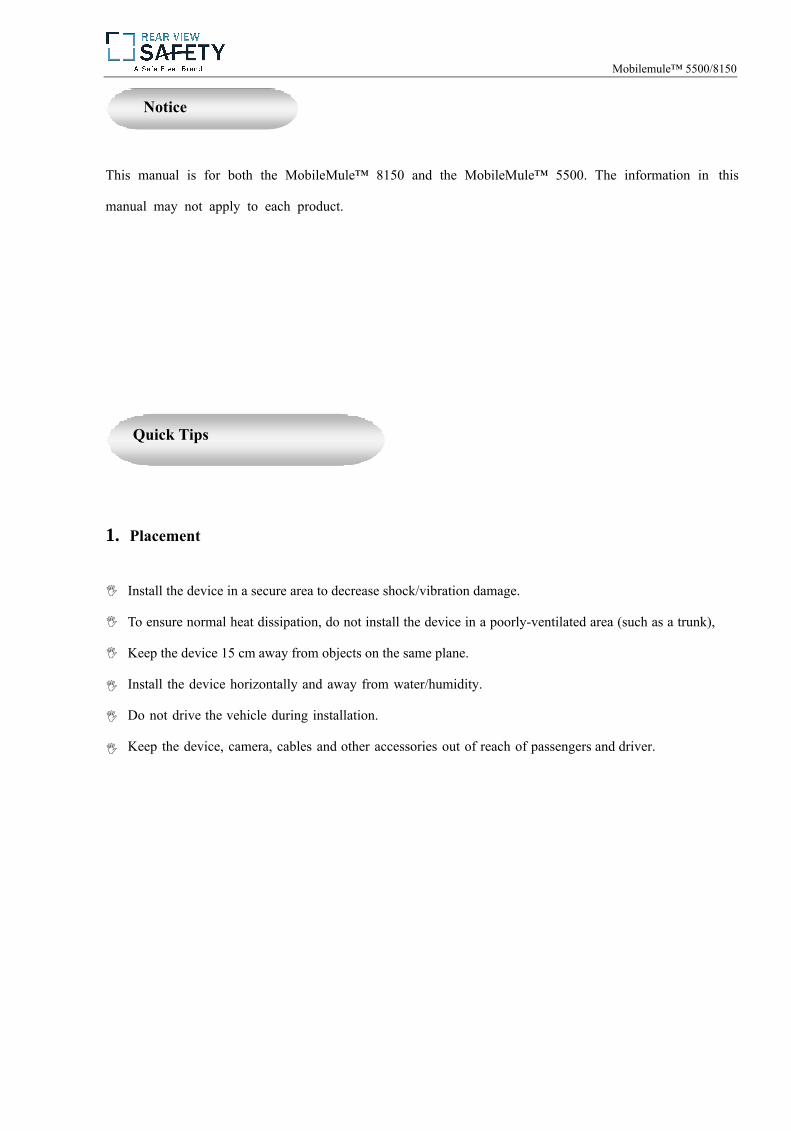
1. Placement
Quick Tips
Notice
Install the device in a secure area to decrease shock/vibration damage.
To ensure normal heat dissipation, do not install the device in a poorly-ventilated area (such as a trunk),
Keep the device 15 cm away from objects on the same plane.
Install the device horizontally and away from water/humidity.
Do not drive the vehicle during installation.
Keep the device, camera, cables and other accessories out of reach of passengers and driver.
Mobilemule™ 5500/8150
2. Avoiding Electric Shock
Power input: 8-36V DC power
Make sure device is off before connecting any cables.
Do not touch the power supply or device with wet hands;
Do not spray liquid on the device in case of internal short circuit or fire.
Do not place any other device directly on top of the camera.
Do not disassemble the housing.
3. Transport and Handling
Handle device with care and use original packaging materials and carton when transporting.
Turn device off before attaching/replacing any parts.
Mobilemule™ 5500/8150
Table of Contents
I. Product Description ................................................................................................................................ - 1 -1. Product overview .................................................................................................................................- 1 -2. Technical specifications. .......................................................................................................................- 2 -3. Mainframe introduction........................................................................................................................- 6 -4. Introduction to remote control.. ............................................................................................................- 8 -
II . Device Installation ...................................................................................................................................... - 10 - Installation ............................................................................................................................................- 10 -
Step 1: Open the protective cover ...................................................................................................- 10 - Step 2: Prepare the HDD .................................................................................................................- 10 - Step 3: Insert the HDD ....................................................................................................................- 11 - Step 4: Install SIM and SD cards ....................................................................................................- 12 - Step 5: Locking the electric lock .....................................................................................................- 13 -Step 6: Install the mainframe ..........................................................................................................- 13 - Step 7: Install GPS, 3G/4G, WiFi antenna ......................................................................................- 13 - Step 8: Connect the power cord ......................................................................................................- 14 - Step 9: Connect the display output unit ..........................................................................................- 15 - Step 10: Alarm input and output cable ............................................................................................- 16 - Step 11: RS232 device connection ................................................................................................. - 17 - Step 12: Connect PTZ .................................................................................................................... - 18 -
MobileMule™ 5500/8150
Step 1: Go to General Settings................................................................................................. .........- 22 -Step 2: Set Date & Time ...................................................................................................................- 22 -Step 3: Set Vehicle Info... ................................................................................................................. - 23 -Step 4: User Setup ............................................................................................................................ - 23 - Step 5: Network Setup ..................................................................................................................... - 24 - Step 6: Display Setup ....................................................................................................................... - 25 -
1. Channel Settings.................................................................................................................................. .- 26 -2. Channel Mode ...................................................................................................................................... - 26 -
3. Recording Setup: ................................................................................................................................... - 28 -Step 1: Enter the Record Setup Interface ......................................................................................... - 28 -Step 2: Record Basic Setup .............................................................................................................. - 28 - Step 3: Main Code ............................................................................................................................ - 29 - Step 4: Sub-Stream Setup ................................................................................................................. - 30 - Step 5: Recording Schedule (Set in timing record mode)................................................................ .- 31 -Step 6: Mirror Record ...................................................................................................................... - 32 - Step 7: SD Record ............................................................................................................................ - 32 - Step 8: Alarm Record ....................................................................................................................... - 33 - Step 9: IPC ....................................................................................................................................... - 34 -
4. Alarm Setup: ........................................................................................................................................ - 35 - Step 1: Enter the Alarm Setup interface ........................................................................................... - 35 - Step 2: Sensor Setup......................................................................................................................... - 36 - Step 3: Speed Setup .......................................................................................................................... - 36 - Step 4: G-sensor Setup ..................................................................................................................... - 37 - Step 5: Temperature Setup ............................................................................................................... - 38 - Step 6: Linkage Setup ...................................................................................................................... - 38 -
III. Basic Settings.....................................................................................................................................................- 21 -
MobileMule™ 5500/8150
Step 7: Motion Detection ................................................................................................................. - 39 - 5. Configuration: ...................................................................................................................................... - 41 -
Step 1: Configuration Management ..................................................................................................- 41 -Step 2: Formatting ............................................................................................................................ - 42 -
Step 3: Log Search ........................................................................................................................... - 43 -
6.Peripheral Setup: ................................................................................................................................... - 43 - Step 1: Enter the Peripheral Setup interface ..................................................................................... - 43 - Step 2: PTZ ...................................................................................................................................... - 44 - Step 3: Wireless Setup ...................................................................................................................... - 44 - Step 4: WiFi Setup ........................................................................................................................... - 45 - Step 5: Oil Setup .............................................................................................................................. - 46 - Step 6: Serial Device Setup .............................................................................................................. - 47 - Step 7: BSM Setup ............................................................................................................................- 47 -
7. System Information: ............................................................................................................................. - 48 - Appendix 1: Frequently Asked Questions ........................................................................................................ - 49 -Appendix 2: Storage Table.................................................................................................................................- 55 -Upgrading ................................................................................................................................................. ......- 57 -Notes..................................................................................................................................................................- 57 -
Mobilemule™ 5500/8150
- 1 -
Product Description
Supports H.264 compression encoding 5500:100fps@720P PAL, 8150:200fps@960H PAL
5500/8150 support 4/8 channel audio/video recording and playback simultaneously.
Air video interface provides reliable shock protection
Built-in 3G/4G network, GPS, WiFi (optional)
Built-in 2.5" HDD, max. 1TB HDD supported, damping technique.
Good scalability, 1 RS485 interface, 2 RS232 interfaces
MobilemMule™ 5500/8150
1. Product Overview
The MobileMule™ 5500/8150 is a 4/8 channel mobile DVR. It uses an ARM DSP fast dual-core processor running on the Linux embedded OS, and integrates the most advanced H.264video encoding/decoding in IT industry. It has 3G/4G network capability, GPS, and fail-safeprotection against HDD vibration and overheating.
- 2 -
Voltage Input: 8V-36V
Voltage Output: 12V (+/- 0.2V)
Operating temperature: -40℃ ~ + 80℃
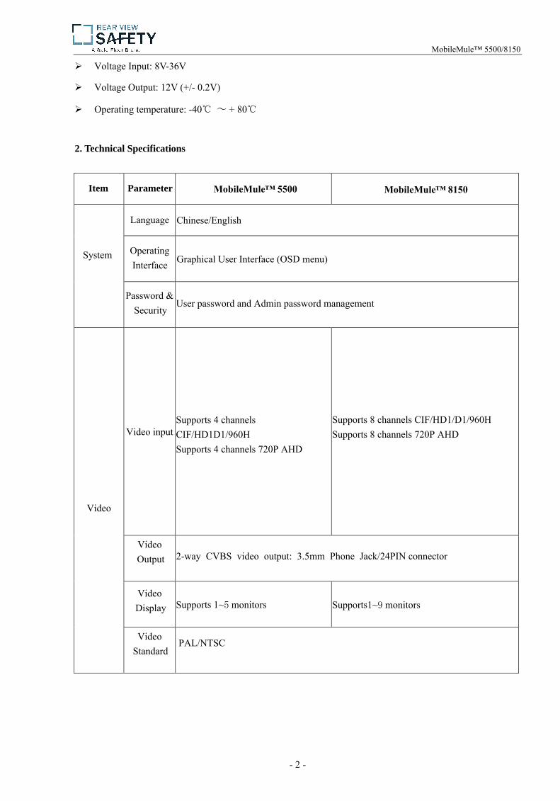
2. Technical Specifications
Item Parameter MobileMule™ 5500 MobileMule™ 8150
System
Language Chinese/English
Operating Interface Graphical User Interface (OSD menu)
Password & Security
User password and Admin password management
Video
Video input Supports 4 channels CIF/HD1D1/960H Supports 4 channels 720P AHD
Supports 8 channels CIF/HD1/D1/960H Supports 8 channels 720P AHD
Video Output 2-way CVBS video output: 3.5mm Phone Jack/24PIN connector
Video Display Supports 1~5 monitors Supports1~9 monitors
Video Standard
PAL/NTSC
MobileMule™ 5500/8150

- 3 -
Image Compression
H.264 Main profile, PAL: 100 frames720P/s, NTSC: 120 frames 720P/s
H.264 Main profile, PAL: 200 frames 960H/s,NTSC: 240 frames 960H/s
Audio
Audio Input 4 audio inputs 8 audio inputs
Audio Output 2 audio outputs (3.5mm Phone Jack/24PIN connector)
Recording Mode Synchronous video & audio recording
Image Processing& Storage
Image Format
CIF/D1/960H/720P optional CIF/D1/960H optional
Video StreamingStandard
ISO14496-10
Video BitRate
CIF: 1536Kbps ~ 128Kbps
HD1: 2048Kbps ~ 400Kbps
D1: 2048Kbps ~ 400Kbps
960H: 2048Kbps ~ 400Kbps
720P: 4096Kbps ~ 400Kbps
Eight picture quality levels are available, with level 1 being the highest and level 8 being the lowest
Audio BitRate
40Kbps
Storage Max. 2T HDD/SSD One SD card supported. When the HDD is damaged, recordings are backup up onto SD card. (3G/4G module is optional)
Alarm Alarm input
Eight alarm inputs. Toggle between the lower level alarm (1V or below) and upperlevel alarm (5V or above)
Alarm Output
One alarm output, the higher level of this output is up to 12V
Communication RS485 Interface
One RS485 interface supported
MobileMule™ 5500/8150
- 4 -
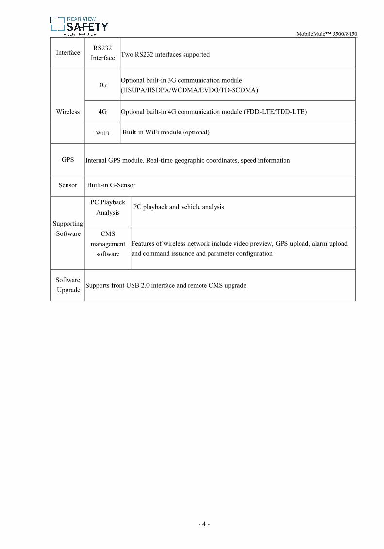
InterfaceRS232
Interface Two RS232 interfaces supported
Wireless
3G Optional built-in 3G communication module (HSUPA/HSDPA/WCDMA/EVDO/TD-SCDMA)
4G Optional built-in 4G communication module (FDD-LTE/TDD-LTE)
WiFi Built-in WiFi module (optional)
GPS Internal GPS module. Real-time geographic coordinates, speed information
Sensor Built-in G-Sensor
Supporting Software
PC Playback Analysis
PC playback and vehicle analysis
CMSmanagement
software Features of wireless network include video preview, GPS upload, alarm uploadand command issuance and parameter configuration
Software Upgrade Supports front USB 2.0 interface and remote CMS upgrade
MobileMule™ 5500/8150

- 5 -
Electrical Specs:
Power Supply+8~+36V
8V~36V (Check the supply voltage of vehicle battery before use; ifbattery is supplied with more than 36V for a prolonged period, thedevice could be damaged)
Power Output 12V 12V(+/-0.2V), max. current: 3A
ACC Detection
≤4V Power off
≥5V Power on
Video InputResistance
75Ω 75Ω
Video OutputVoltage 2Vp-p
2VP-P CVBS output analog signal to be used with 75Ω of inputresistance
I/O Interface1V Or Below Low level alarm
5V Or Above High level alarm
Working Temperature -40℃~80℃
MobileMule™ 5500/8150
-40℃~80℃
- 6 -
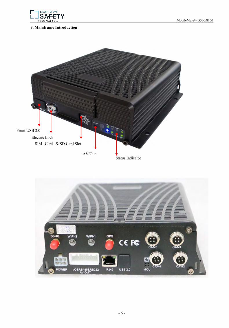
3. Mainframe Introduction
Front USB 2.0
Electric Lock SIM Card & SD Card Slot
AV/Out Status Indicator
MobileMule™ 5500/8150

- 7 -
MobileMule™ 5500 Interface Diagram
MobileMule™ 5500/8150
MobileMule™ 8150 Interface Diagram

- 8 -
4. Introduction to Remote Control
Login After setting a password, press the login key to input your password. The system has no recover/reset features, do not forget your password.
键
Power key
MobileMule™ 5500/8150
View system information
Press the quad view button to toggle between single and quad view. Use the numerical buttons 1-4 to display channel 1-4 and channel respectively.
Info
Quad View + Numerical
Buttons
- 9 -
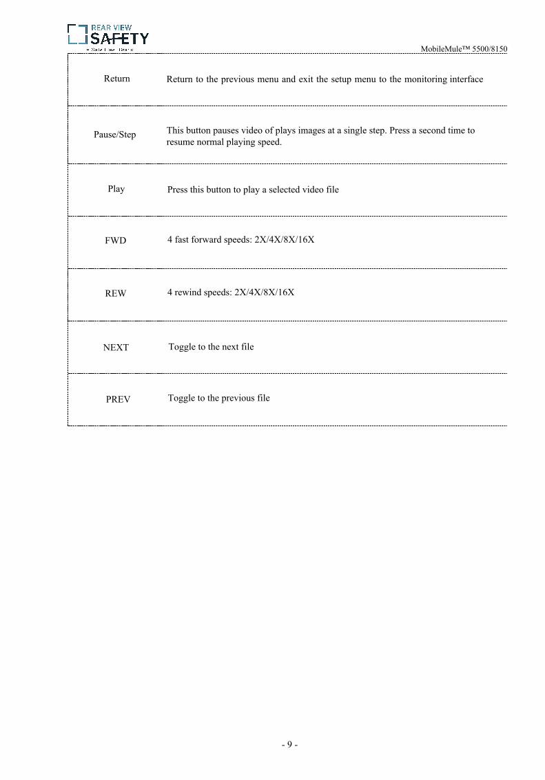
Return
Pause/Step
Play
FWD
REW
NEXT
PREV
Return to the previous menu and exit the setup menu to the monitoring interface
MobileMule™ 5500/8150
This button pauses video of plays images at a single step. Press a second time to resume normal playing speed.
Press this button to play a selected video file
4 fast forward speeds: 2X/4X/8X/16X
4 rewind speeds: 2X/4X/8X/16X
Toggle to the next file
Toggle to the previous file
- 10 -
II. Device and Installation
1. Installation
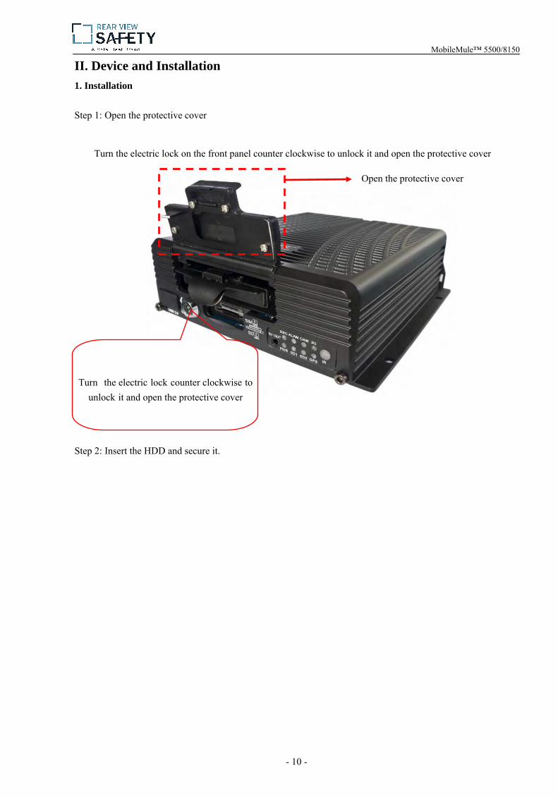
Step 1: Open the protective cover
Turn the electric lock on the front panel counter clockwise to unlock it and open the protective cover
Step 2: Insert the HDD and secure it.
Turn the electric lock counter clockwise tounlock it and open the protective cover
Open the protective cover
MobileMule™ 5500/8150
- 11 -
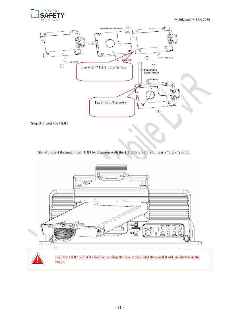
Step 3: Insert the HDD
Slowly insert the machined HDD by aligning with the HDD box until you hear a "click" sound.
Take the HDD out of its box by holding the box handle and then pull it out, as shown in the image.
Insert 2.5" HDD into its box
Fix it with 4 screws
Mobilemule™ 5500/8150
- 12 -
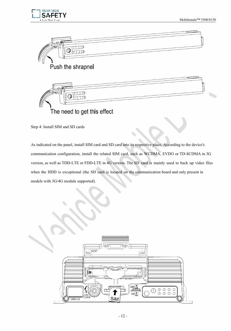
Step 4: Install SIM and SD cards
As indicated on the panel, install SIM card and SD card into its respective place. According to the device's
communication configuration, install the related SIM card, such as WCDMA, EVDO or TD-SCDMA in 3G
version, as well as TDD-LTE or FDD-LTE in 4G version. The SD card is mainly used to back up video files
when the HDD is exceptional (the SD card is located on the communication board and only present in
models with 3G/4G module supported).
Mobilemule™ 5500/8150

- 13 -
Step 5: Lock the electric lock
After all units are installed, close the protective cover, and then turn the electric lock clockwise to lock it;
otherwise, the device cannot be powered on.
Step 6: Install the mainframe
According to indicated MDVR mounting hole size, install the device in a proper place of the vehicle.
Step 7: Install GPS, 3G/4G, WiFi antenna
Mobilemule™ 5500/8150

- 14 -
As shown in the following figure, connect GPS, 3G/4G and WiFi antenna to corresponding interface on
the rear panel of the MDVR and keep wires well arranged to protect the signal from external interference.
GPS 3G 4G
Step 8: Connect the power cord
Connect the air power cord to 6PIN power input interface on the rear panel of the MDVR (If it is in white,
the 6pin cable shall be connected with an adapter), while the red and black cables are directly connected to the
battery of the vehicle, i.e. positive terminal and negative terminal respectively. The yellow cable is connected to
ACC, the vehicle control circuit switch (used to start the vehicle motor). The unit will be enabled automatically
when the car key is enabled and disabled when the key is disabled.
When the device is not installed in a vehicle (such as monitoring systems in bus station, logistic transfer) or
under test, you can use a switching power above DC12V-5A to supply the mainframe. In this case, twist the red
and yellow cables as a cable to connect it to the positive terminal, while the black one is connected to the
negative terminal separately.
Mobilemule™ 5500/8150

- 15 -
It is suggested that the vehicle mounted machine be directly powered from positive and negative terminals of the battery cell, or led from the mains power at the fuse without use of ground strap, which may influence normal operation of the mainframe due to negative pulse; The power cable used for positive and negative terminals shall have diameter of φ1.5mm or above.
Step 9: Connect the display output unit
This product supports one HDMI and two CVBS video outputs (one is φ3.5 Phone Jack on the front panel,
and the other is 24PIN connector). A customer can connect to the display unit according actual conditions.
Connect the 3-in-1 terminal of the supplied 4pin-AV output cable to the φ3.5 Phone Jack on the front panel, and
the other terminal to the display unit.
This terminal is connected to the power interface on the rear panel of the MDVR
Before connecting, check that the voltage ranges from 8V to 36V. If not, the device will be suspended.

- 16 -
Step 10: Alarm input and output cable
A: Sensor input alarm cable
Connect the external sensor to set with alarm feature to 8 external alarm input ports of the I/O sensor on the
rear panel of the MDVR. The external alarm inputs shall be connected to related sensor switching units, such as
door magnet power, emergency switch, turn signal switch and brake light, as shown in the following figure.
For example: the following block diagram shows that high level is detected when the brake pad is
stepped down; otherwise, low level will be detected. Thus, braking operation may trigger device alarm.
B: Over-speed alarm cable
- 17 -
a: If a speed is acquired from GPS, requiring normal GPS signal, the alarm feature can be enabled by
simply configuring settings via Setup menu -> Alarm -> Speed.
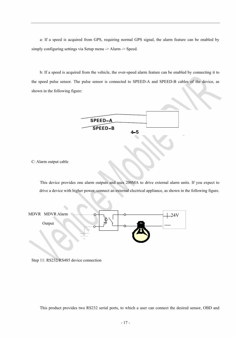
b: If a speed is acquired from the vehicle, the over-speed alarm feature can be enabled by connecting it to
the speed pulse sensor. The pulse sensor is connected to SPEED-A and SPEED-B cables of the device, as
shown in the following figure:
C: Alarm output cable
This device provides one alarm outputs and uses 200MA to drive external alarm units. If you expect to
drive a device with higher power, connect an external electrical appliance, as shown in the following figure.
Step 11: RS232/RS485 device connection
This product provides two RS232 serial ports, to which a user can connect the desired sensor, OBD and
24V MDVR MDVR Alarm
Output

- 18 -
two-way radio supporting RS232 according to actual requirements. Before installation, firstly connect the power
cord and communication cable of the external device to the supplied 24pin I/O port, and then to 24PIN I/O port
on the rear panel of the MobileMule™ Finally, install the probe for the external device and keep cables well
arranged. The following shows the schematic connection diagram:
Step 12: Connect PTZ
There are three methods for connecting PTZ in terms of PTZ control method:
The first method is connect the RS485 control cable of the PTZ to the RS485A and RS485B of the main
frame, connect the video cable to the mainframe video input, and then power the PTZ. At the same time,
configure the PTZ setting corresponding to PTZ data under the peripheral setup option to use the remote
control to control the PTZ.
- 19 -
After the PTZ is connected and parameters are set, you shall select the channel connected to the
PTZ before using the remote control to control the PTZ. For example, if the PTZ is connected to
Channel 2, then you can control it only after switching the monitoring interface to Channel 2
and maximizing it.
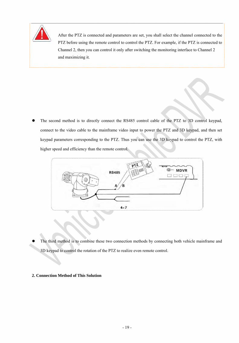
The second method is to directly connect the RS485 control cable of the PTZ to 3D control keypad,
connect to the video cable to the mainframe video input to power the PTZ and 3D keypad, and then set
keypad parameters corresponding to the PTZ. Thus you can use the 3D keypad to control the PTZ, with
higher speed and efficiency than the remote control.
The third method is to combine these two connection methods by connecting both vehicle mainframe and
3D keypad to control the rotation of the PTZ to realize even remote control.
2. Connection Method of This Solution
- 20 -
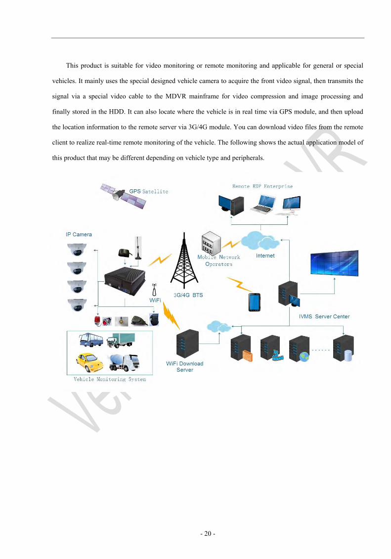
This product is suitable for video monitoring or remote monitoring and applicable for general or special
vehicles. It mainly uses the special designed vehicle camera to acquire the front video signal, then transmits the
signal via a special video cable to the MDVR mainframe for video compression and image processing and
finally stored in the HDD. It can also locate where the vehicle is in real time via GPS module, and then upload
the location information to the remote server via 3G/4G module. You can download video files from the remote
client to realize real-time remote monitoring of the vehicle. The following shows the actual application model of
this product that may be different depending on vehicle type and peripherals.
- 21 -
III. Basic Settings
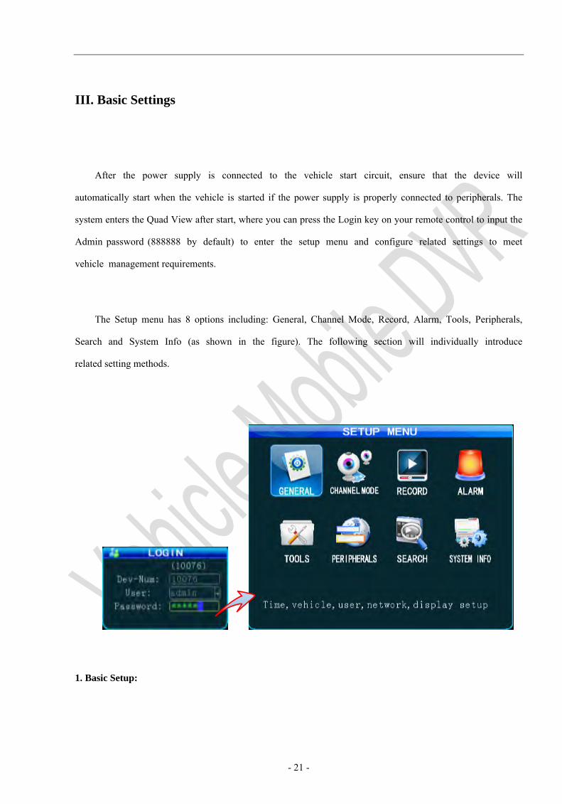
After the power supply is connected to the vehicle start circuit, ensure that the device will
automatically start when the vehicle is started if the power supply is properly connected to peripherals. The
system enters the Quad View after start, where you can press the Login key on your remote control to input the
Admin password (888888 by default) to enter the setup menu and configure related settings to meet
vehicle management requirements.
The Setup menu has 8 options including: General, Channel Mode, Record, Alarm, Tools, Peripherals,
Search and System Info (as shown in the figure). The following section will individually introduce
related setting methods.
1. Basic Setup:
- 22 -
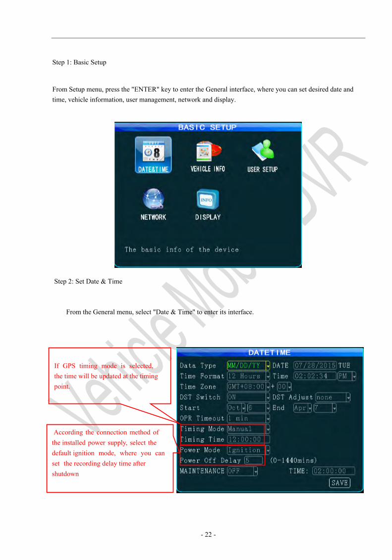
Step 1: Basic Setup
From Setup menu, press the "ENTER" key to enter the General interface, where you can set desired date and time, vehicle information, user management, network and display.
Step 2: Set Date & Time
From the General menu, select "Date & Time" to enter its interface.
If GPS timing mode is selected, the time will be updated at the timing point.
According the connection method of the installed power supply, select the default ignition mode, where you can set the recording delay time after shutdown

- 23 -
1. It is advised to enable the auto-maintenance feature when the device is operating for aprolonged time, allowing that the device automatically restarts within the set maintenancetime.
2. OPR Timeout meaning the quit automatically time if you don't operate, Other options areset as required and after setting.
Step 3: Set Vehicle INFO
Press the "Return" key to return to the General menu to enter the Vehicle Info menu. To facilitate
unified management of vehicles on the server, it is recommended to completely fill in vehicle information.
Step 4: User Setup
1. The report can be founded on the CMS client only when the mileage statistic is started;
2. After setting, move your cursor to the "Save" key and press the "ENTER" key to save it.
The server will monitor and manage vehicles through device number. When vehicles are managed via 3G/4G network, please ensure the uniqueness of the device number.
Please ensure your vehicle number is correct which will be superimposed on the video.
- 24 -
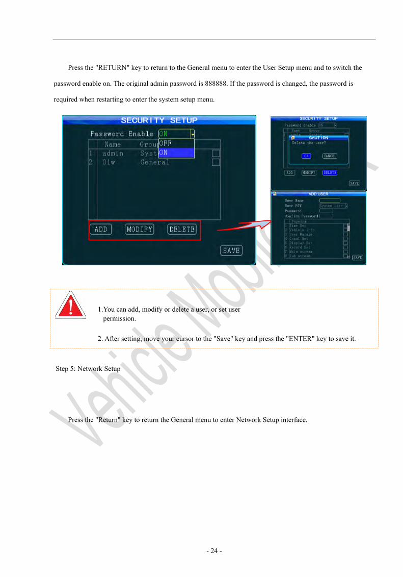
Press the "RETURN" key to return to the General menu to enter the User Setup menu and to switch the
password enable on. The original admin password is 888888. If the password is changed, the password is
required when restarting to enter the system setup menu.
1.You can add, modify or delete a user, or set user permission.
2. After setting, move your cursor to the "Save" key and press the "ENTER" key to save it.
Step 5: Network Setup
Press the "Return" key to return the General menu to enter Network Setup interface.
- 25 -
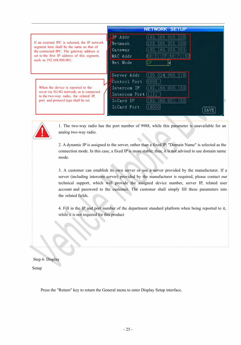
1. The two-way radio has the port number of 9988, while this parameter is unavailable for ananalog two-way radio.
2. A dynamic IP is assigned to the server, rather than a fixed IP, "Domain Name" is selected as theconnection mode. In this case, a fixed IP is more stable; thus, it is not advised to use domain name mode.
3. A customer can establish its own server or use a server provided by the manufacturer. If aserver (including intercom server) provided by the manufacturer is required, please contact our technical support, which will provide the assigned device number, server IP, related user account and password to the customer. The customer shall simply fill these parameters into the related fields.
4. Fill in the IP and port number of the department standard platform when being reported to it,while it is not required for this product
Step 6: Display
Setup
Press the "Return" key to return the General menu to enter Display Setup interface.
If an external IPC is selected, the IP network segment here shall be the same as that of the connected IPC. The gateway address is set to the first IP address of this segment, such as 192.168.000.001.
When the device is reported to the sever via 3G/4G network, or is connected to the two-way radio, the related IP, port and protocol type shall be set.
- 26 -
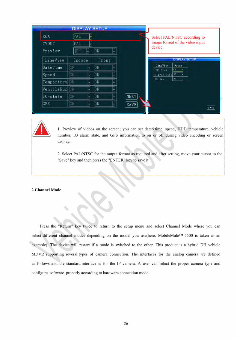
1. Preview of videos on the screen; you can set date&time, speed, HDD temperature, vehicle number, IO alarm state, and GPS information to on or off during video encoding or screen display. 2. Select PAL/NTSC for the output format as required and after setting, move your cursor to the "Save" key and then press the "ENTER" key to save it.
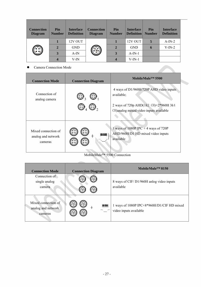
2.Channel Mode
Press the "Return" key twice to return to the setup menu and select Channel Mode where you can
select different channel modes depending on the model you use(here, MobileMule™ 5500 is taken as an
example). The device will restart if a mode is switched to the other. This product is a hybrid DH vehicle
MDVR supporting several types of camera connection. The interfaces for the analog camera are defined
as follows and the standard interface is for the IP camera. A user can select the proper camera type and
configure software properly according to hardware connection mode.
Select PAL/NTSC according to image format of the video input device.
- 27 -
Connection
Diagram
Pin
Number
Interface
Definition
Connection
Diagram
Pin
Number
Interface
Definition
Pin
Number
Interface
Definition
1 12V OUT 1 12V OUT 5 A-IN-2
2 GND 2 GND 6 V-IN-2
3 A-IN 3 A-IN-1
4 V-IN 4 V-IN-1
Camera Connection Mode
Connection Mode Connection Diagram MobileMule™ 5500
Connection of analog camera 3 1
4 2
4 ways of D1/960H/720P AHD video inputs available;
2 ways of 720p AHD(1&2 CH)+2*960H 3&4 CH)analog mixed video inputs available
Mixed connection of analog and network
cameras
1 ways of 1080P IPC + 4 ways of 720P AHD/960H/D1 HD mixed video inputs available
MobileMule™ 5500 Connection
Connection Mode Connection Diagram MobileMule™ 8150
Connection of single analog
camera 8 ways of CIF/ D1/960H anlog video inputs available
Mixed connection of analog and network
cameras
1 ways of 1080P IPC+8*960H/D1/CIF HD mixed video inputs available
- 28 -
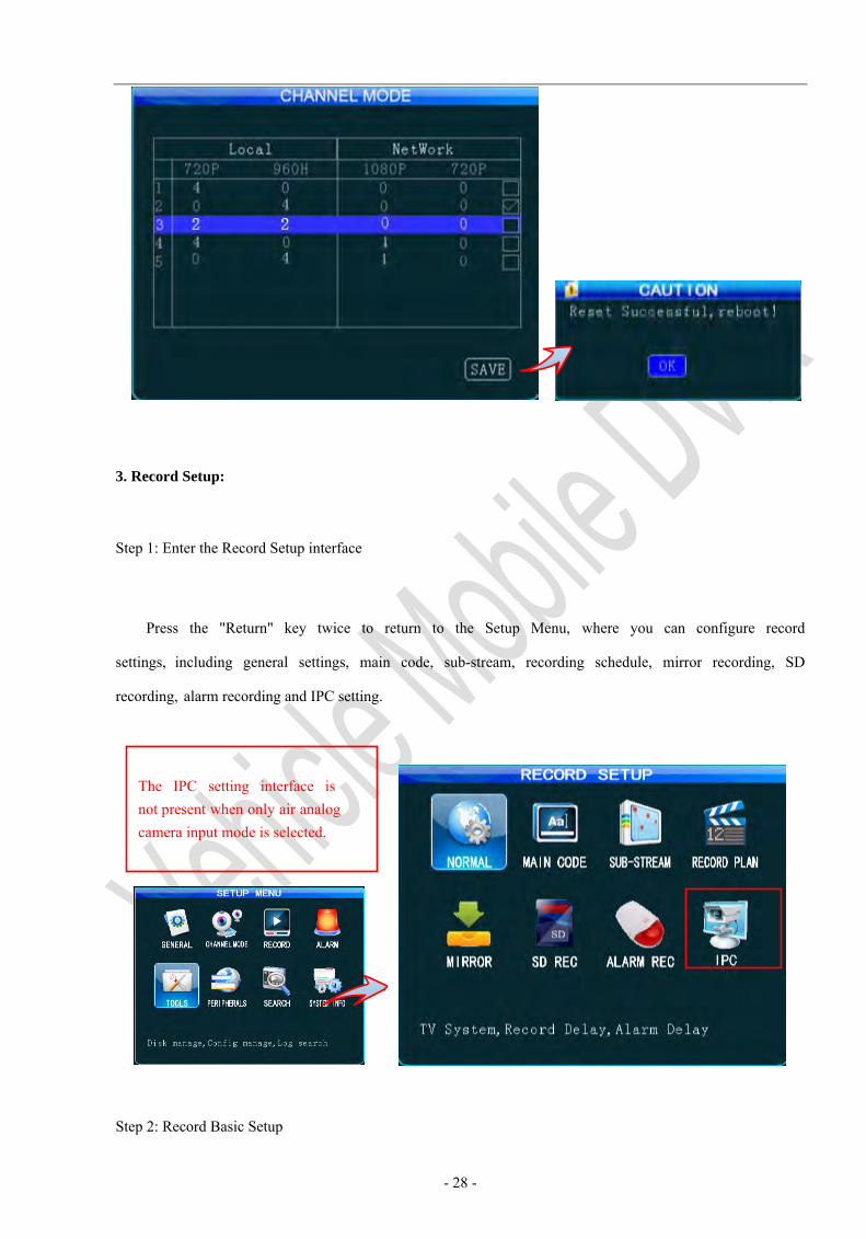
3. Record Setup:
Step 1: Enter the Record Setup interface
Press the "Return" key twice to return to the Setup Menu, where you can configure record
settings, including general settings, main code, sub-stream, recording schedule, mirror recording, SD
recording, alarm recording and IPC setting.
Step 2: Record Basic Setup
The IPC setting interface is not present when only air analog camera input mode is selected.
- 29 -
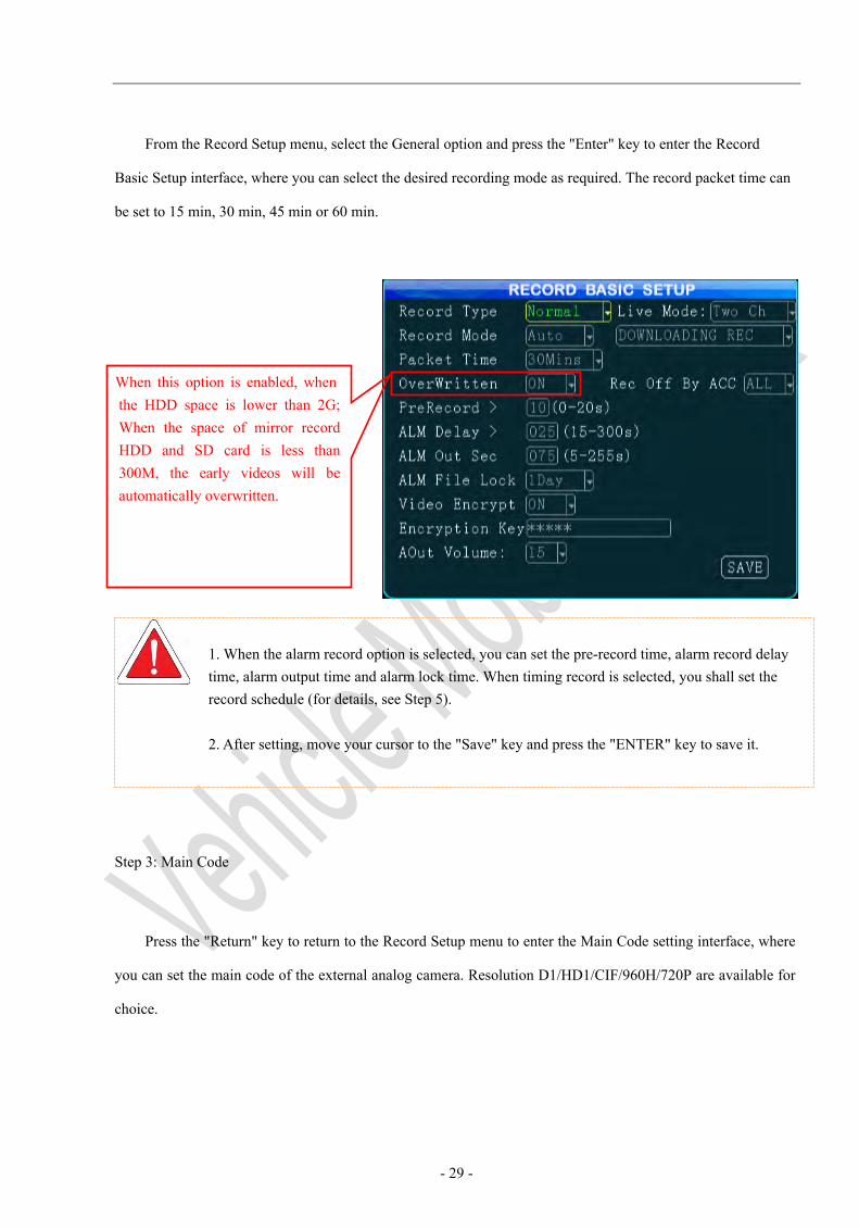
From the Record Setup menu, select the General option and press the "Enter" key to enter the Record
Basic Setup interface, where you can select the desired recording mode as required. The record packet time can
be set to 15 min, 30 min, 45 min or 60 min.
1. When the alarm record option is selected, you can set the pre-record time, alarm record delaytime, alarm output time and alarm lock time. When timing record is selected, you shall set therecord schedule (for details, see Step 5).
2. After setting, move your cursor to the "Save" key and press the "ENTER" key to save it.
Step 3: Main Code
Press the "Return" key to return to the Record Setup menu to enter the Main Code setting interface, where
you can set the main code of the external analog camera. Resolution D1/HD1/CIF/960H/720P are available for
choice.
When this option is enabled, when the HDD space is lower than 2G; When the space of mirror record HDD and SD card is less than 300M, the early videos will be automatically overwritten.
- 30 -
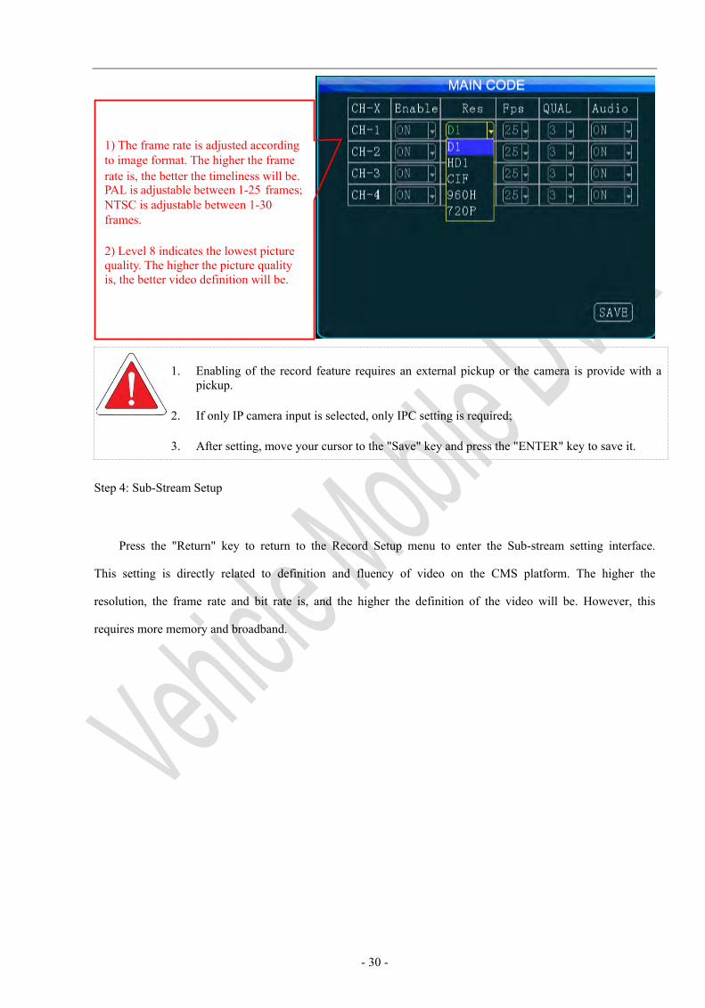
1. Enabling of the record feature requires an external pickup or the camera is provide with a pickup.
2. If only IP camera input is selected, only IPC setting is required;
3. After setting, move your cursor to the "Save" key and press the "ENTER" key to save it.
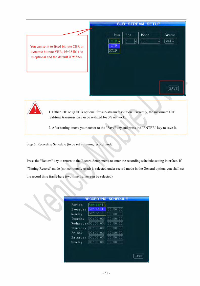
Step 4: Sub-Stream Setup
Press the "Return" key to return to the Record Setup menu to enter the Sub-stream setting interface.
This setting is directly related to definition and fluency of video on the CMS platform. The higher the
resolution, the frame rate and bit rate is, and the higher the definition of the video will be. However, this
requires more memory and broadband.
1) The frame rate is adjusted according to image format. The higher the frame rate is, the better the timeliness will be. PAL is adjustable between 1-25 frames; NTSC is adjustable between 1-30 frames.
2) Level 8 indicates the lowest picture quality. The higher the picture quality is, the better video definition will be.
- 31 -
1. Either CIF or QCIF is optional for sub-stream resolution. Currently, the maximum CIF real-time transmission can be realized for 3G network;
2. After setting, move your cursor to the "Save" key and press the "ENTER" key to save it.
Step 5: Recording Schedule (to be set in timing record mode)
Press the "Return" key to return to the Record Setup menu to enter the recording schedule setting interface. If
"Timing Record" mode (not commonly used) is selected under record mode in the General option, you shall set
the record time frame here (two time frames can be selected).
You can set it to fixed bit rate CBR or dynamic bit rate VBR, 16-384bit/s is optional and the default is 96bit/s.
- 32 -
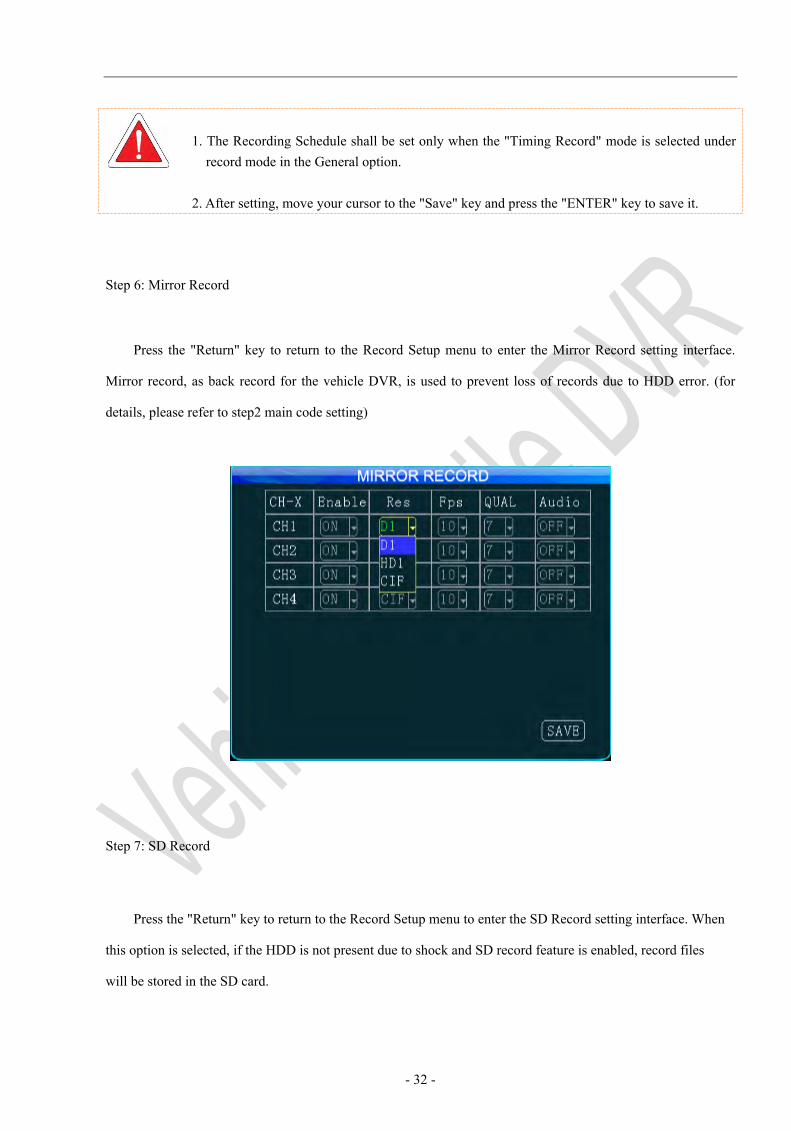
1. The Recording Schedule shall be set only when the "Timing Record" mode is selected under record mode in the General option.
2. After setting, move your cursor to the "Save" key and press the "ENTER" key to save it.
Step 6: Mirror Record
Press the "Return" key to return to the Record Setup menu to enter the Mirror Record setting interface.
Mirror record, as back record for the vehicle DVR, is used to prevent loss of records due to HDD error. (for
details, please refer to step2 main code setting)
Step 7: SD Record
Press the "Return" key to return to the Record Setup menu to enter the SD Record setting interface. When
this option is selected, if the HDD is not present due to shock and SD record feature is enabled, record files
will be stored in the SD card.
- 33 -
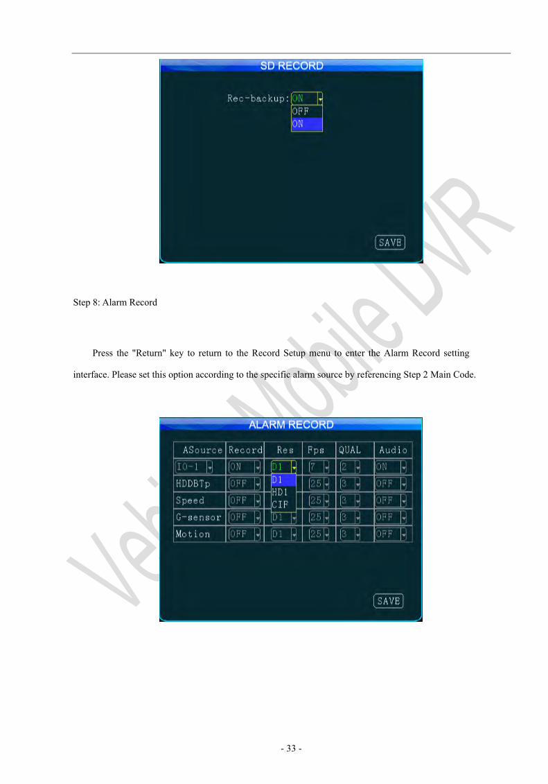
Step 8: Alarm Record
Press the "Return" key to return to the Record Setup menu to enter the Alarm Record setting
interface. Please set this option according to the specific alarm source by referencing Step 2 Main Code.
- 34 -
1. This feature is planning.... Under normal circumstances, you shall simply set related parameters related to the main code (for example, the main code resolution is set to HD1 or CIF, frame rate is set to 25 frames and the picture quality is set to 3). When the record operation is triggered by an alarm, the alarm record file can be recorded according to set high quality video parameters;
2. After setting, move your cursor to the "Save" key and press the "ENTER" key to save it.
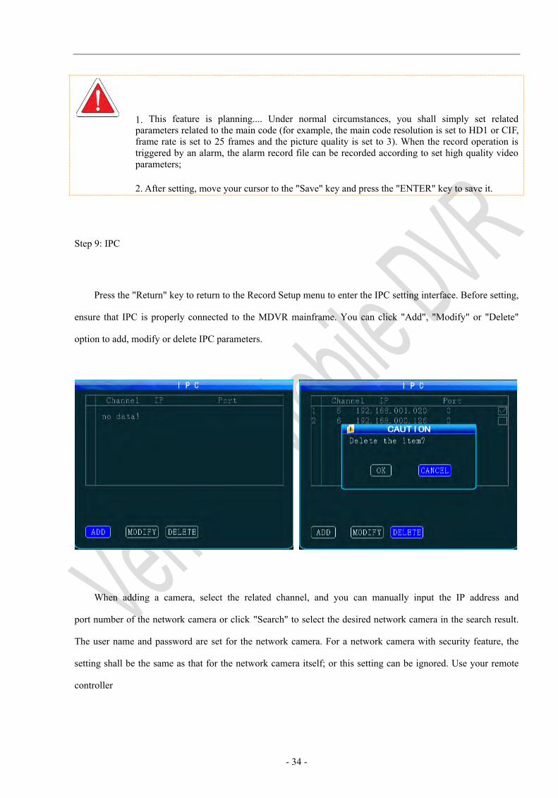
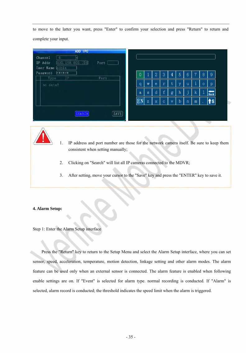
Step 9: IPC
Press the "Return" key to return to the Record Setup menu to enter the IPC setting interface. Before setting,
ensure that IPC is properly connected to the MDVR mainframe. You can click "Add", "Modify" or "Delete"
option to add, modify or delete IPC parameters.
When adding a camera, select the related channel, and you can manually input the IP address and
port number of the network camera or click "Search" to select the desired network camera in the search result.
The user name and password are set for the network camera. For a network camera with security feature, the
setting shall be the same as that for the network camera itself; or this setting can be ignored. Use your remote
controller
- 35 -
to move to the latter you want, press "Enter" to confirm your selection and press "Return" to return and
complete your input.
1. IP address and port number are those for the network camera itself. Be sure to keep themconsistent when setting manually;
2. Clicking on "Search" will list all IP cameras connected to the MDVR;
3. After setting, move your cursor to the "Save" key and press the "ENTER" key to save it.
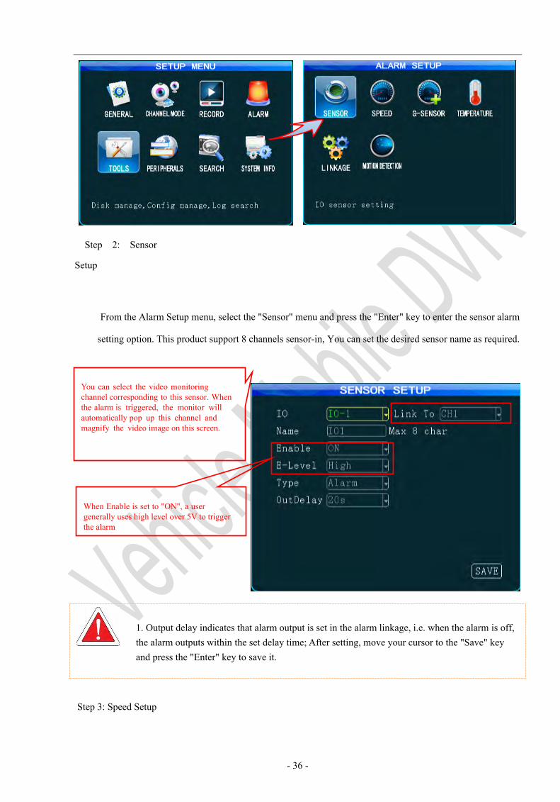
4. Alarm Setup:
Step 1: Enter the Alarm Setup interface
Press the "Return" key to return to the Setup Menu and select the Alarm Setup interface, where you can set
sensor, speed, acceleration, temperature, motion detection, linkage setting and other alarm modes. The alarm
feature can be used only when an external sensor is connected. The alarm feature is enabled when following
enable settings are on. If "Event" is selected for alarm type. normal recording is conducted. If "Alarm" is
selected, alarm record is conducted; the threshold indicates the speed limit when the alarm is triggered.
- 36 -
Step 2: Sensor
Setup
From the Alarm Setup menu, select the "Sensor" menu and press the "Enter" key to enter the sensor alarm
setting option. This product support 8 channels sensor-in, You can set the desired sensor name as required.
1. Output delay indicates that alarm output is set in the alarm linkage, i.e. when the alarm is off, the alarm outputs within the set delay time; After setting, move your cursor to the "Save" key and press the "Enter" key to save it.
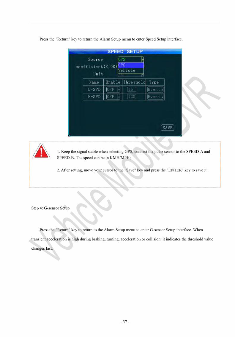
Step 3: Speed Setup
You can select the video monitoring channel corresponding to this sensor. When the alarm is triggered, the monitor will automatically pop up this channel and magnify the video image on this screen.
When Enable is set to "ON", a user generally uses high level over 5V to trigger the alarm
- 37 -
Press the "Return" key to return the Alarm Setup menu to enter Speed Setup interface.
1. Keep the signal stable when selecting GPS; connect the pulse sensor to the SPEED-A and SPEED-B. The speed can be in KMH/MPH;
2. After setting, move your cursor to the "Save" key and press the "ENTER" key to save it.
Step 4: G-sensor Setup
Press the "Return" key to return to the Alarm Setup menu to enter G-sensor Setup interface. When
transient acceleration is high during braking, turning, acceleration or collision, it indicates the threshold value
changes fast.
- 38 -
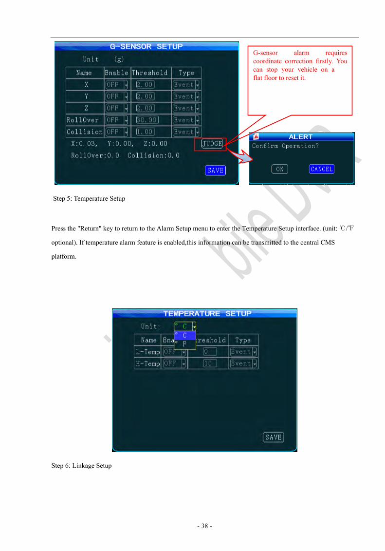
Step 5: Temperature Setup
Press the "Return" key to return to the Alarm Setup menu to enter the Temperature Setup interface. (unit: ℃/℉
optional). If temperature alarm feature is enabled,this information can be transmitted to the central CMS
platform.
Step 6: Linkage Setup
G-sensor alarm requires coordinate correction firstly. You can stop your vehicle on a flat floor to reset it.
- 39 -
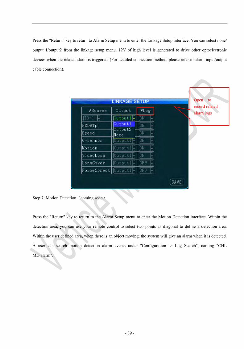
Press the "Return" key to return to Alarm Setup menu to enter the Linkage Setup interface. You can select none/
output 1/output2 from the linkage setup menu. 12V of high level is generated to drive other optoelectronic
devices when the related alarm is triggered. (For detailed connection method, please refer to alarm input/output
cable connection).
Step 7: Motion Detection(coming soon)
Press the "Return" key to return to the Alarm Setup menu to enter the Motion Detection interface. Within the
detection area, you can use your remote control to select two points as diagonal to define a detection area.
Within the user defined area, when there is an object moving, the system will give an alarm when it is detected.
A user can search motion detection alarm events under "Configuration -> Log Search", naming "CHL
MD alarm".
Open to record related alarm logs
- 40 -
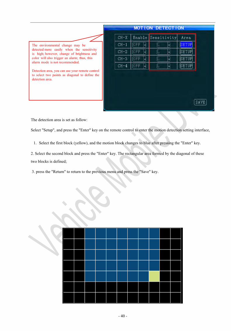
The detection area is set as follow:
Select "Setup", and press the "Enter" key on the remote control to enter the motion detection setting interface,
1. Select the first block (yellow), and the motion block changes to blue after pressing the "Enter" key.
2. Select the second block and press the "Enter" key. The rectangular area formed by the diagonal of these
two blocks is defined;
3. press the "Return" to return to the previous menu and press the "Save" key.
The environmental change may be detected more easily when the sensitivity is high; however, change of brightness and color will also trigger an alarm; thus, this alarm mode is not recommended.
Detection area, you can use your remote control to select two points as diagonal to define the detection area.
- 41 -
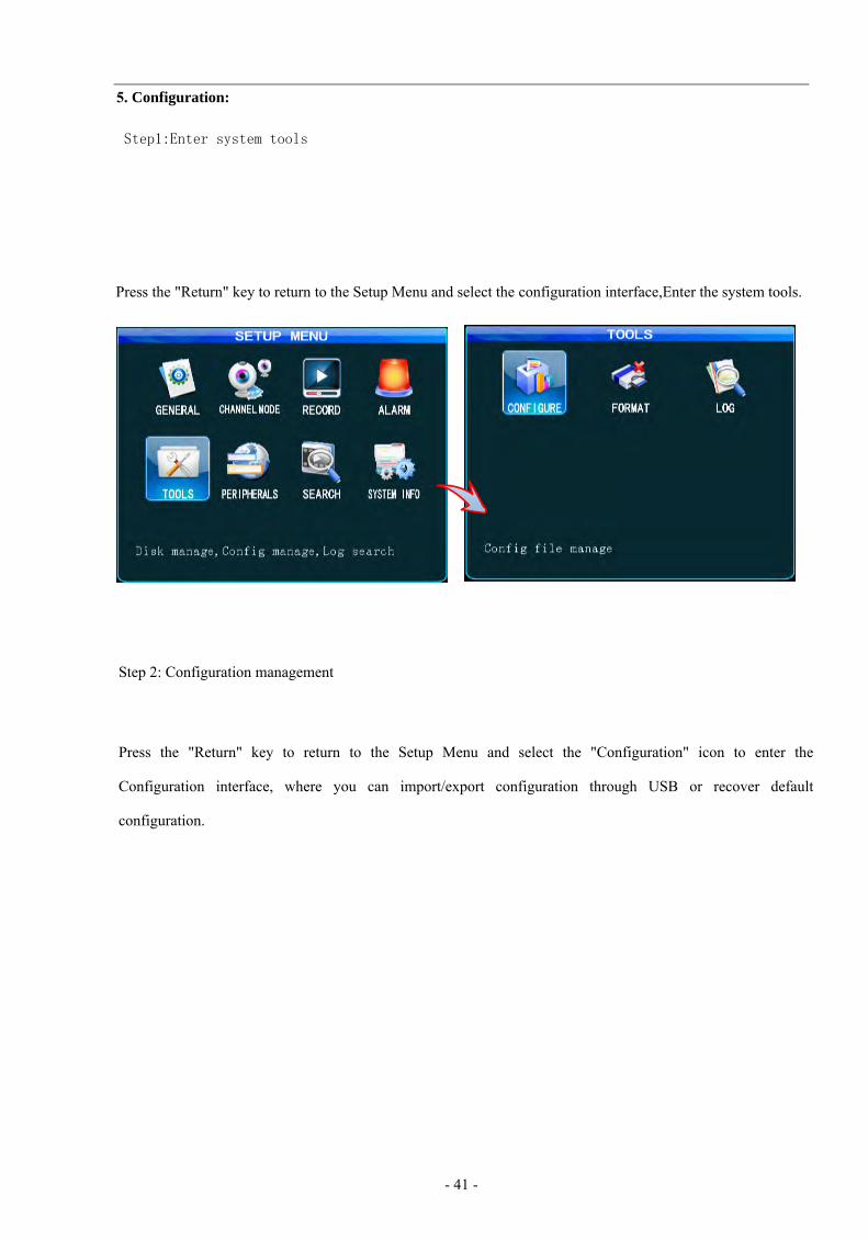
5. Configuration:
Step1:Enter system tools
Press the "Return" key to return to the Setup Menu and select the configuration interface,Enter the system tools.
Step 2: Configuration management
Press the "Return" key to return to the Setup Menu and select the "Configuration" icon to enter the
Configuration interface, where you can import/export configuration through USB or recover default
configuration.

- 42 -
Step 2: Formatting
Press the "Return" key to return to the Setup Menu to enter the Format setting interface, where you can
select the storage medium to be formatted and press the "Format" button.
1. The HDD shall be formatted before being inserted into its box;2.2. Formatting will clear all data stored in the memory. Please check if there is important
1. 3G and WiFi shall be disabled before export, import, upgrading logo operation;
You can use the front USB interface to import preset configuration or exported to save current settings.
Logo image size: 720*576name and format: loading.jpg, upgrading.jpg

- 43 -
Step 3: Log Search
Press the "Return" key to return to the Configuration menu to enter the Log Search setting interface.
6.Peripheral Setup:
Step 1: Enter the Peripheral Setup interface
Press the "Return" key to return to the Setup Menu to select the Peripherals icon to enter the Peripheral
Setup interface, where you can set PTZ, wireless broadband, WiFi, Oil, serial port.
The calendar with a green background indicates that there is a log that can be searched by simply selecting date, time and log type.
- 44 -
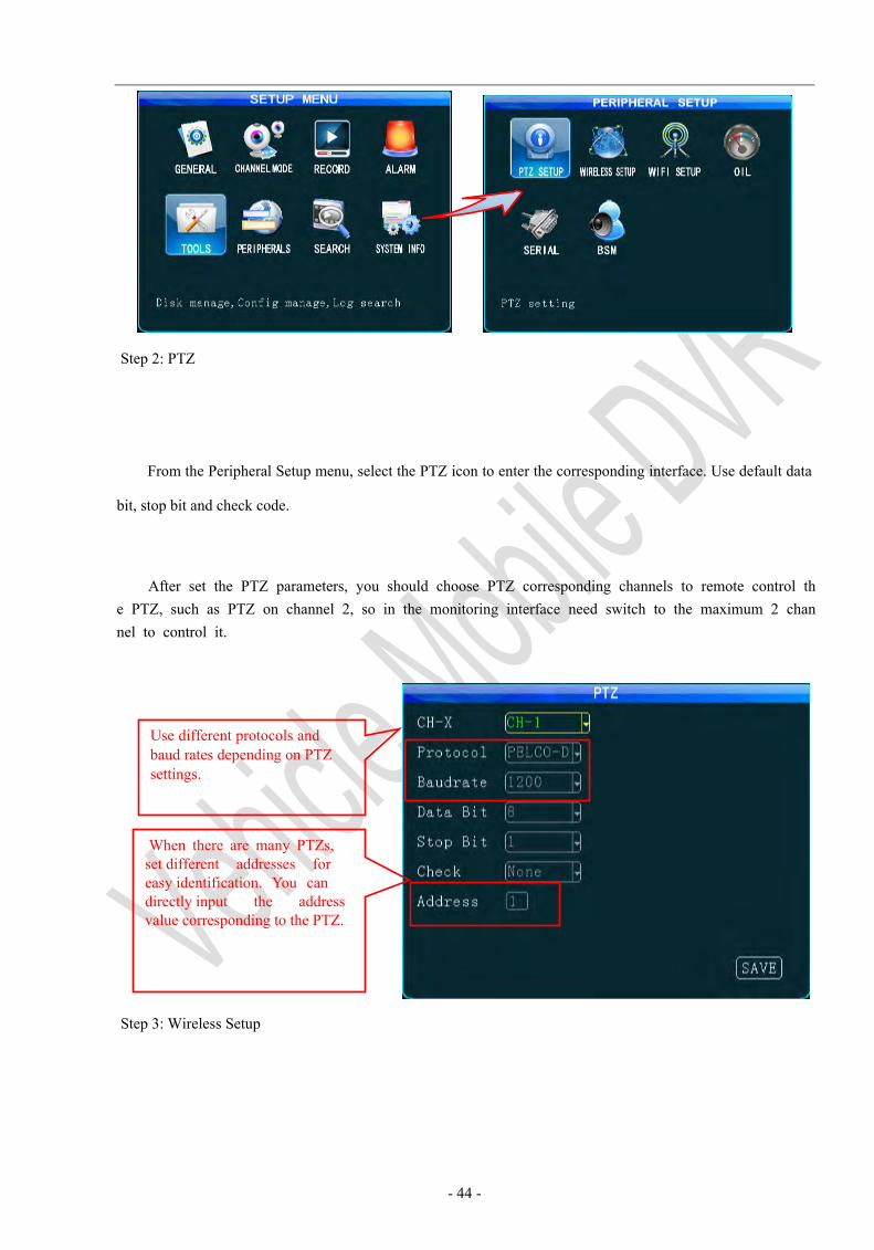
Step 2: PTZ
From the Peripheral Setup menu, select the PTZ icon to enter the corresponding interface. Use default data
bit, stop bit and check code.
After set the PTZ parameters, you should choose PTZ corresponding channels to remote control th e PTZ, such as PTZ on channel 2, so in the monitoring interface need switch to the maximum 2 chan nel to control it.
Step 3: Wireless Setup
Use different protocols and baud rates depending on PTZ settings.
When there are many PTZs, set different addresses for easy identification. You can directly input the address value corresponding to the PTZ.
- 45 -
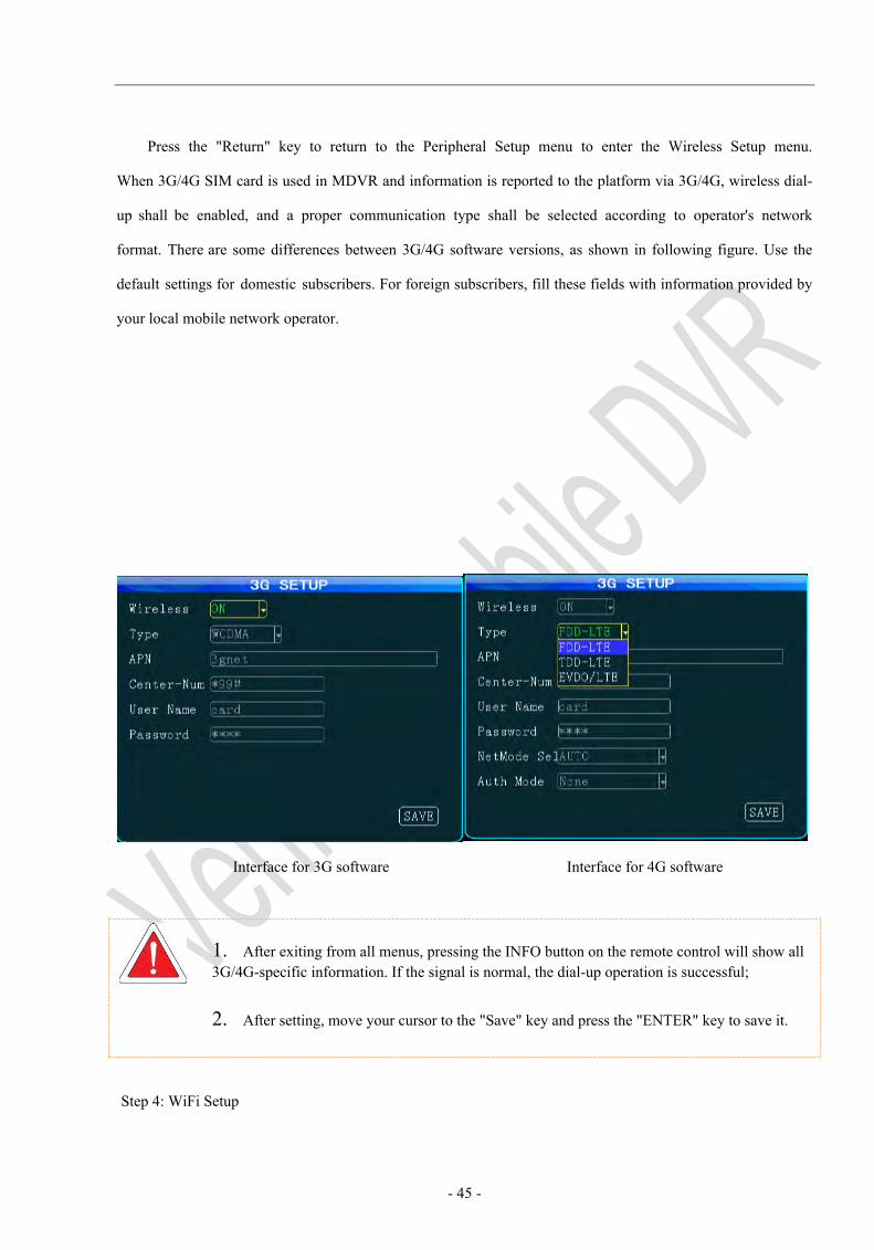
Press the "Return" key to return to the Peripheral Setup menu to enter the Wireless Setup menu.
When 3G/4G SIM card is used in MDVR and information is reported to the platform via 3G/4G, wireless dial-
up shall be enabled, and a proper communication type shall be selected according to operator's network
format. There are some differences between 3G/4G software versions, as shown in following figure. Use the
default settings for domestic subscribers. For foreign subscribers, fill these fields with information provided by
your local mobile network operator.
Interface for 3G software Interface for 4G software
1. After exiting from all menus, pressing the INFO button on the remote control will show all 3G/4G-specific information. If the signal is normal, the dial-up operation is successful;
2. After setting, move your cursor to the "Save" key and press the "ENTER" key to save it.
Step 4: WiFi Setup
- 46 -
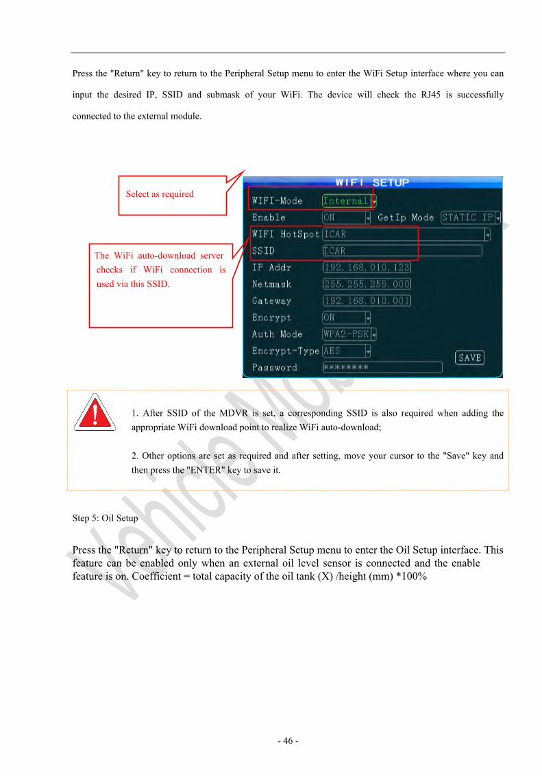
Press the "Return" key to return to the Peripheral Setup menu to enter the WiFi Setup interface where you can
input the desired IP, SSID and submask of your WiFi. The device will check the RJ45 is successfully
connected to the external module.
1. After SSID of the MDVR is set, a corresponding SSID is also required when adding the appropriate WiFi download point to realize WiFi auto-download;
2. Other options are set as required and after setting, move your cursor to the "Save" key and then press the "ENTER" key to save it.
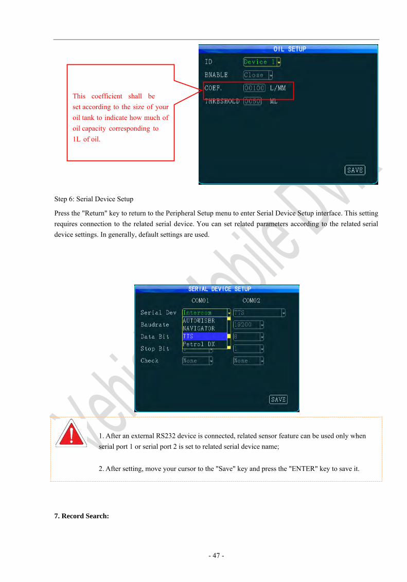
Step 5: Oil Setup
Press the "Return" key to return to the Peripheral Setup menu to enter the Oil Setup interface. This feature can be enabled only when an external oil level sensor is connected and the enable feature is on. Coefficient = total capacity of the oil tank (X) /height (mm) *100%
Select as required
The WiFi auto-download server checks if WiFi connection is used via this SSID.
- 47 -
Step 6: Serial Device Setup
Press the "Return" key to return to the Peripheral Setup menu to enter Serial Device Setup interface. This setting requires connection to the related serial device. You can set related parameters according to the related serial device settings. In generally, default settings are used.
1. After an external RS232 device is connected, related sensor feature can be used only whenserial port 1 or serial port 2 is set to related serial device name;
2. After setting, move your cursor to the "Save" key and press the "ENTER" key to save it.
7. Record Search:
This coefficient shall be set according to the size of your oil tank to indicate how much of oil capacity corresponding to 1L of oil.
- 48 -
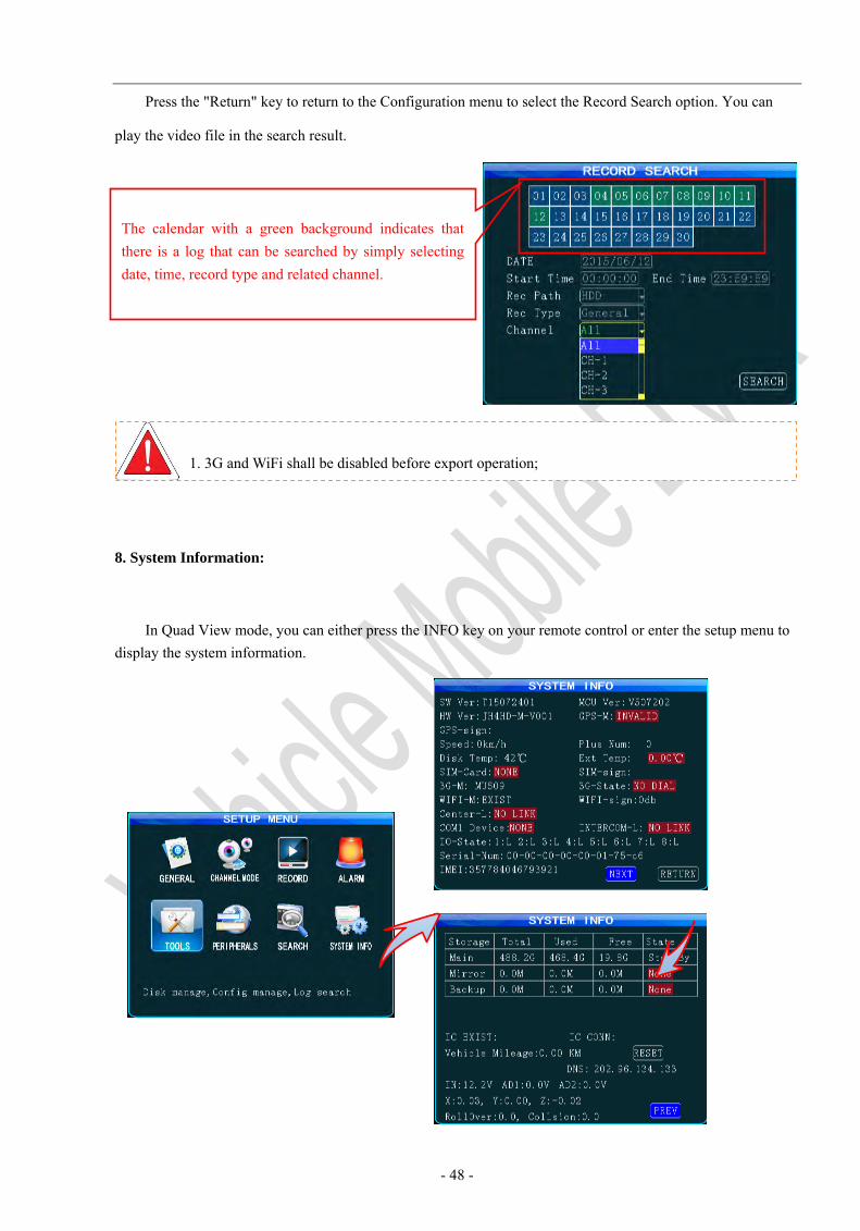
Press the "Return" key to return to the Configuration menu to select the Record Search option. You can
play the video file in the search result.
8. System Information:
In Quad View mode, you can either press the INFO key on your remote control or enter the setup menu to display the system information.
1. 3G and WiFi shall be disabled before export operation;
The calendar with a green background indicates that there is a log that can be searched by simply selecting date, time, record type and related channel.
- 49 -
Appendix 1: Frequently Asked Questions
Q: What shall we do when a problem that could not be solve occurs to the product?
A: Record product model and software version number and submit detailed problem description to our technical
support engineer for analysis. Detailed description will be very helpful to our analysis.
Q: What shall we do when the mobile device has no video output?
A: 1. Check the power status of the device. If only one blue indicator is lit up, it indicates that the device is
still in standby mode and not powered on; at the same time, check if red or yellow cable of the main
power is supplied normally; If not, the device cannot be started.
2. Check if the display is powered and if the display video is switched to AV status.
3. Check the connection status of the video output cable and display.
4. Check the lock status the mainframe lock; the device can be started only when the lock is locked.
Q: What shall we do when the mainframe video input interface is different from the camera input
interface?
A: a 4-pin interface is used for the vehicle device. BNC interface or air interface is used for the camera. If
inconsistency is found, please use an adapter or connect it to a standard line defined as the line sequence for the
vehicle device.
- 50 -
Q: What shall we do if recording is unavailable even when the device is powered on and HDD is installed?
A: 1. Check that the HDD is formatted after HDD is installed and HDD without formatting cannot be used.
From the Main Menu-Management Tool-Formatting, format the newly-installed HDD.
2. Check if the record channel is off or if timing record is set. Recording is unavailable when it is not within the recording time frame.
3. Check if the HDD is properly contacted, and the HDD on the front panel is lit up.
Q: A record file is lost or no record file is found within a certain period of time?
A: 1. Analyze to define the period of time between the final video file is lost and the first video file is recovered.
2. Check if the device is power on within this period of time, for example, delay record not set while the
pppp device is turning off or unloading/loading.
Q: The vehicle PTZ cannot be controlled and cannot be rotated to up, down, right and left?
A: Check if the protocol and baud rate of the PTZ are set correctly, the address is consistent and if the
channel video is selected to be maximized when controlling the PTZ. For example, when controlling the second
channel, you shall maximize the image in the second channel to control the PTZ.
- 51 -
GPS frequently asked questions
Q: GPS module is present but no coordinate information is available?
A: 1. Check if the GPS module is present; if not, please check if the HDD is installed or properly contacted.
2. Check if GPS antenna is properly contacted and if the antenna is broken. The antenna is recommended to be placed in an area having strong signal. Note that some car glass shielding film may form a GPS signal.
3. If the test is conducted indoors and the GPS antenna set indoors is shielded, it is recommended to place the GPS antenna outdoors.
Q: GPS geographic position is not accurately displayed on the map?
A: if the GPS module is positioned, it indicates that the signal is valid. Government limitation, error tolerance or
GPS signal interrupt may cause deviation; The satellite map may have some deviation by for the sake of safety.
In general, this problem can be solved by using GPS correction.
3G/4G wireless related problems
Q: What shall be noted if 3G wireless module is used for dial up?
A: If built-in wireless module WCDMA or EVDO is selected, the module settings are different and also
depend on the model used; thus, please check the consistency between the module used and SIM card. Do
not use
- 52 -
Telecom Card in WCDMA-enabled devices.
2. Check if the server IP or port is correctly set, if 3G/4G signal is intense enough for dial up, and if dial up
via 3G/4G is successful.
3. Please check if the 3G/4G antenna is properly contacted when dial up fails. Weak signal may result in
failure to dial up; in addition, check if the SIM card has sufficient traffic; if not, dial up will also fail.
Q: What shall we do when no video is reported via 3G/4G?
A: press the "INFO" key to enter the System Information page, where you can check if the SIM card is present,
inspect signal intensity and dial-up status, and check if the antenna is properly contacted. Then, check if the SIM
card has traffic and replace it will a new one to re-check it. This is a most basic judgment criteria. If a signal is
available, while dial up fails, check if the center number and port are set correctly. Then, check if the
device number is unique.
Q: 3G/4G signal is intermittent and video is not smooth
A: So far, WCDMA and EVDO has good coverage (4G is desired to be improved). In case where signal is
not covered in some mountainous areas or signal is weak due to local network restrictions in some suburban
areas, the video may not be smooth or even cannot be viewed. In this case, it is largely affected by the local
network; in addition, check if the frame rate for the sub stream is set too high. This may occur when
the network condition is poor while the frame rate is high.
- 53 -
Q: Connection is impossible even when WiFi signal is up to -60db
A: If your WiFi is correctly set, connection is generally not a problem when signal intensity is up to -60db. If
the device cannot be found within LAN, check if SSID and password are correctly set. Of course, the IP
address shall be properly set; in addition, check the encryption type and authentication mode are set to
requirements.
CMS Frequently Asked Questions
Q: The device is powered on while the CMS client displays no vehicle information and video
A: Firstly, check the central registration server is powered on and online and then check if the device number
is used, thereby causing conflict; secondly, check if the IP and port number are set correctly for the server
center; Check if the device reports information to the central server via built-in 3G module or WiFi. If the built-
in 3G is used, check if the right type is selected; for example, WCDMA and EVDO corresponds to related
SIM cards. Check if the antenna is properly contacted, if data access point and center number are correctly
set. If it still does not work, please collect information as much as possible and submit it to technical support
for analysis to facilitate troubleshooting.
Q: the device is online but video image is not displayed?
- 54 -
A: Please set a lower sub-stream to transmit images. When the sub-stream is set too high, block or slower
transmission rate may result due to upload limit of the network; the video transmission may be seriously
affected due to weak network signal or intermittence.
Q: the device normally reports information to the CMS while video cannot be displayed after a period of
time?
A: Firstly, check if the device information displays dial-up. If yes, the traffic for the SIM card may be used
up. Please replace with a new one for test; secondly, check if the device number is tampered. If yes, your
vehicle information shall be reported again to the server; thirdly, if card replacement cannot still solve this
problem, check if the device 3G module is faulty.
- 55 -
Appendix 2: MobileMule™ 5500
Memory Space Reference
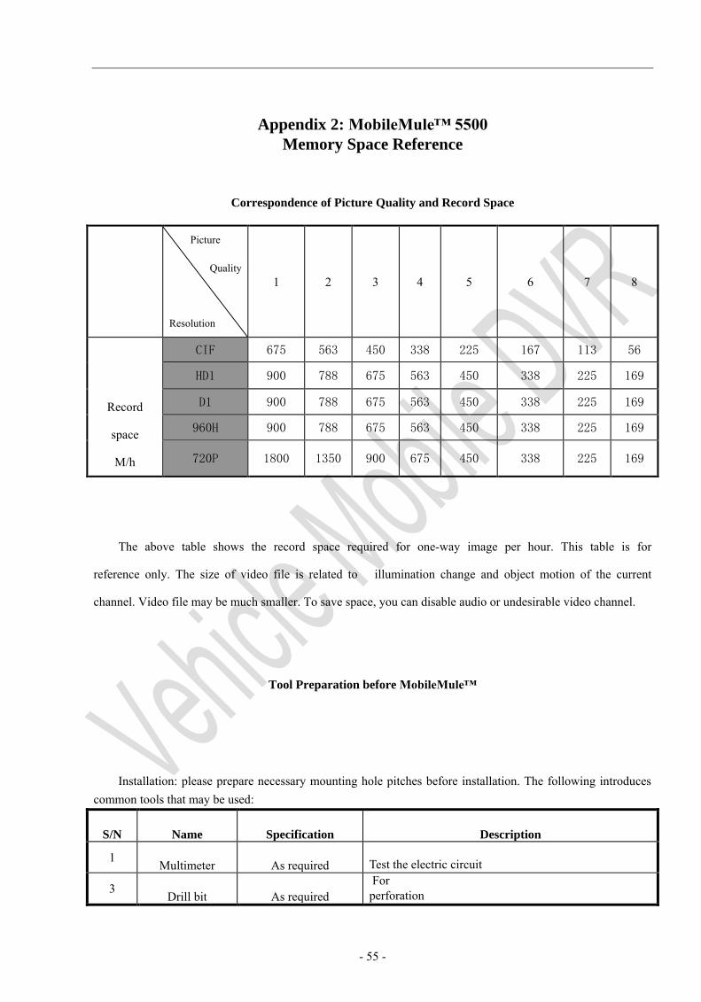
Correspondence of Picture Quality and Record Space
Picture
Quality
Resolution
1 2 3 4 5 6 7 8
Record
space
M/h
CIF 675 563 450 338 225 167 113 56
HD1 900 788 675 563 450 338 225 169
D1 900 788 675 563 450 338 225 169
960H 900 788 675 563 450 338 225 169
720P 1800 1350 900 675 450 338 225 169
The above table shows the record space required for one-way image per hour. This table is for
reference only. The size of video file is related to illumination change and object motion of the current
channel. Video file may be much smaller. To save space, you can disable audio or undesirable video channel.
Tool Preparation before MobileMule™
Installation: please prepare necessary mounting hole pitches before installation. The following introduces common tools that may be used:
S/N Name Specification Description
1 Multimeter As required Test the electric circuit
3 Drill bit As required For perforation
- 56 -
4 Remote control Special tool For device debugging
5 Electroprobe As required Test the electric circuit
6 Display Special tool For device debugging
7 Wire stripper As required For stripping
8 Screwdriver As required For device maintenance
9 Allen wrench As required For device maintenance
11 Tape As required For measurement
12 Cutting plier As required For cutting
13 Pincer plier As required For cutting
14 Electric screwdriver As required For device maintenance
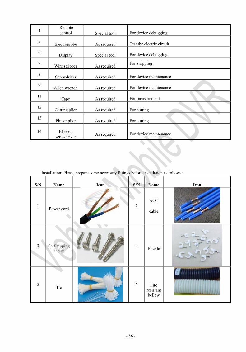
Installation: Please prepare some necessary fittings before installation as follows:
S/N Name Icon S/N Name Icon
1 Power cord 2 ACC
cable
3 Self-tapping screw
4 Buckle
5 Tie 6 Fire resistant bellow
- 57 -
7 Electrical insulating
tape
Notes/Upgrade
History
S/N Revision Upgrade / Change Description Issue Date Revised by Note
1
2
3