Mobile robotic fabrication at 1:1 scale: the In situ Fabricator · PDF fileMobile robotic...
12
ORIGINAL PAPER Mobile robotic fabrication at 1:1 scale: the In situ Fabricator System, experiences and current developments Markus Giftthaler 1 • Timothy Sandy 1 • Kathrin Do ¨rfler 2 • Ian Brooks 3 • Mark Buckingham 4 • Gonzalo Rey 3 • Matthias Kohler 2 • Fabio Gramazio 2 • Jonas Buchli 1 Received: 30 December 2016 / Accepted: 24 May 2017 / Published online: 12 June 2017 Ó Springer International Publishing Switzerland 2017 Abstract This paper presents the concept of an In situ Fabricator, a mobile robot intended for on-site manufacturing, assembly and digital fabrication. We present an overview of a prototype system, its capabilities, and highlight the impor- tance of high-performance control, estimation and planning algorithms for achieving desired construction goals. Next, we detail on two architectural application scenarios: first, build- ing a full-size undulating brick wall, which required a number of repositioning and autonomous localisation manoeuvres. Second, the mesh mould concrete process, which shows that an In situ Fabricator in combination with an innovative digital fabrication tool can be used to enable completely novel building technologies. Subsequently, important limitations of our approach are discussed. Based on that, we identify the need for a new type of robotic actuator, which facilitates the design of novel full-scale construction robots. We provide brief insight into the development of this actuator and con- clude the paper with an outlook on the next-generation In situ Fabricator, which is currently under development. Keywords Construction robotics Á Digital fabrication Á Mobile manipulation Á In situ fabrication 1 Introduction 1.1 Motivation In the past decades, there has been significant effort to raise the degree of automation in building construction This research was supported by the Swiss National Science Foundation through the National Centre of Competence in Research (NCCR) Digital Fabrication (Agreement #51NF40_141853), a Professorship Award to Jonas Buchli (Agreement #PP00P2_138920) and the Research Equipment Grant #206021_150856. The authors would like to thank Norman Hack, Nitish Kumar and Alexander N. Walzer for providing details on the Mesh Mould process. Special thanks also go to the NCCR technicians Michael Lyrenmann and Philippe Fleischmann for their technical support on IF1. & Markus Giftthaler [email protected] Timothy Sandy [email protected] Kathrin Do ¨rfler doerfl[email protected] Ian Brooks [email protected] Mark Buckingham [email protected] Gonzalo Rey [email protected] Matthias Kohler [email protected] Fabio Gramazio [email protected] Jonas Buchli [email protected] 1 Agile & Dexterous Robotics Lab, ETH Zu ¨rich, Institute of Robotics and Intelligent Systems, Zu ¨rich, Switzerland 2 ETH Zu ¨rich, Chair of Architecture and Digital Fabrication, Zu ¨rich, Switzerland 3 Moog Inc., Buffalo, USA 4 Renishaw PLC., Gloucester, UK 123 Constr Robot (2017) 1:3–14 https://doi.org/10.1007/s41693-017-0003-5
Transcript of Mobile robotic fabrication at 1:1 scale: the In situ Fabricator · PDF fileMobile robotic...

ORIGINAL PAPER
Mobile robotic fabrication at 1:1 scale: the In situ Fabricator
System, experiences and current developments
Markus Giftthaler1• Timothy Sandy1
• Kathrin Dorfler2• Ian Brooks3
•
Mark Buckingham4• Gonzalo Rey3
• Matthias Kohler2• Fabio Gramazio2
•
Jonas Buchli1
Received: 30 December 2016 / Accepted: 24 May 2017 / Published online: 12 June 2017
� Springer International Publishing Switzerland 2017
Abstract This paper presents the concept of an In situ
Fabricator, amobile robot intended for on-sitemanufacturing,
assembly and digital fabrication.We present an overview of a
prototype system, its capabilities, and highlight the impor-
tance of high-performance control, estimation and planning
algorithms for achieving desired construction goals. Next, we
detail on two architectural application scenarios: first, build-
ing a full-size undulating brick wall, which required a number
of repositioning and autonomous localisation manoeuvres.
Second, the mesh mould concrete process, which shows that
an In situ Fabricator in combination with an innovative digital
fabrication tool can be used to enable completely novel
building technologies. Subsequently, important limitations of
our approach are discussed. Based on that, we identify the
need for a new type of robotic actuator, which facilitates the
design of novel full-scale construction robots. We provide
brief insight into the development of this actuator and con-
clude the paper with an outlook on the next-generation In situ
Fabricator, which is currently under development.
Keywords Construction robotics � Digital fabrication �Mobile manipulation � In situ fabrication
1 Introduction
1.1 Motivation
In the past decades, there has been significant effort to
raise the degree of automation in building construction
This research was supported by the Swiss National Science
Foundation through the National Centre of Competence in Research
(NCCR) Digital Fabrication (Agreement #51NF40_141853), a
Professorship Award to Jonas Buchli (Agreement #PP00P2_138920)
and the Research Equipment Grant #206021_150856. The authors
would like to thank Norman Hack, Nitish Kumar and Alexander N.
Walzer for providing details on the Mesh Mould process. Special
thanks also go to the NCCR technicians Michael Lyrenmann and
Philippe Fleischmann for their technical support on IF1.
& Markus Giftthaler
Timothy Sandy
Kathrin Dorfler
Ian Brooks
Mark Buckingham
Gonzalo Rey
Matthias Kohler
Fabio Gramazio
Jonas Buchli
1 Agile & Dexterous Robotics Lab, ETH Zurich, Institute of
Robotics and Intelligent Systems, Zurich, Switzerland
2 ETH Zurich, Chair of Architecture and Digital Fabrication,
Zurich, Switzerland
3 Moog Inc., Buffalo, USA
4 Renishaw PLC., Gloucester, UK
123
Constr Robot (2017) 1:3–14
https://doi.org/10.1007/s41693-017-0003-5

and architecture. Digital fabrication promises a revolu-
tion in the construction industry and exhibits a great
potential for novel architectural approaches and alter-
native tectonics. The tight integration of planning and
construction allows the architect to optimise processes
on multiple levels. During planning, shapes can be
optimised to create highly differentiated forms which
minimise the usage of material. For construction, novel
processes are enabled which minimise material waste,
increase efficiency and improve working conditions. To
handle the high level of geometric- and fabrication-in-
formed complexity in an efficient manner, using digitally
controlled machinery for the construction of computer-
generated forms is essential. Furthermore, by tightly
integrating digital design and fabrication, the perfor-
mance and aesthetics of the structures being built can be
improved through continuous adaptation of the design
and process in real time.
To date, digital fabrication has had the most impact on
the area of off-site prefabrication in which smaller com-
ponents of a building are made in a dedicated factory and
then transported to the building site for final assembly (an
example is the roof presented in Willmann et al. 2016).
Directly on building sites, however, the level of automation
is still comparably low. The final assembly of building
components is heavily dominated by manual labour, which
breaks the digital process chain between design and
making.
Motivated by this insight, recent research goes in the
direction of on-site digital fabrication, the autonomous
fabrication of buildings (or building components) on the
spot, generally referred to as in situ fabrication. Within this
field, one approach addresses on-site additive manufac-
turing with large-scale gantry systems (Khoshnevis 2004;
Bosscher et al. 2007). However, the most striking disad-
vantage of this approach is the fact that the size of the
employed machine constrains the size of the object being
built. Therefore, using mobile, autonomous robots can be
considered a more versatile option as it allows for the
fabrication of structures significantly larger than the tool
employed.
A number of attempts have already been made to
develop mobile robots for on-site robotic construction.
Early exploratory setups deserving explicit mentioning
were the robots ‘‘Rocco’’ (Andres et al. 1994) and
‘‘Bronco’’ (Pritschow et al. 1996). However, these systems
were designed for relatively standardised and strictly
organised production processes. ‘‘Dimrob’’ was presented
in Helm et al. (2012), but several factors restricted the
platform’s usefulness for a wide range of building sce-
narios. It could only be repositioned manually and did not
make use of advanced sensing and control concepts,
therefore requiring the use of static support legs and
effectively rendering it as a movable fixed-base robot.
In Keating (2016), a full-scale mobile system was shown to
be capable of printing a large-scale foam structure, how-
ever also using a quasi fixed-base setup and without strict
accuracy requirements. In Jokic et al. (2015), a self-sup-
porting 3d printing system which can move on the printed
structure was presented. For a recent, more complete sur-
vey of mobile robots in construction, we refer the reader
to Ardiny et al. (2015).
To the best of our knowledge, to date, there is no
robotic platform which fully satisfies the requirements
for autonomous, mobile robotic construction at 1:1 scale.
While there has been a number of research projects
aiming at enabling mobile robots for on-site robotic
construction, we believe that the key challenge which
has prevented significant breakthroughs so far is that
such machines must be able to robustly handle the
unstructured nature of the building construction site.
Because construction sites are constantly changing and
relatively dirty and cluttered environments, it is not
possible to apply classical industrial automation
approaches in controlling such systems.
This challenge poses design, engineering and research
questions at many different levels. While environmental
and hardware requirements (e.g., payload requirements)
determine the design, shape and physical realisation of the
mobile robot itself, the role of state estimation, control and
planning algorithms, as well as their proper implementa-
tions, should be considered in the design of the overall
system such that it can be effectively operated by a non-
expert user. Finally, the system needs to be integrated into
layouting systems and architectural design software in such
a way that there can be a seamless interaction between
design and construction.
1.2 Contributions and structure of this paper
In this paper, we present the ‘‘In situ Fabricator’’ concept: a
class of mobile robots specially designed for on-site digital
fabrication. First, we propose a list of basic requirements
for an In situ Fabricator in Sect. 2. Second, we present a
systematic overview of the IF1, a first prototype built from
off-the-shelf components, in Sect. 3. Next, we introduce
the fully integrated digital tool-chain developed for the
system, spanning from digital design to the planning and
control for the mobile system. In Sect. 4, we present the
planning, state estimation and control algorithms methods
used for achieving the required capabilities for digital
fabrication on IF1. In Sect. 5, we explain the IF1’s inte-
gration into architectural design and planning Software.
We highlight the capabilities of this fully integrated system
through two architectural demonstrators, in Sect. 6. First is
a dry brick wall, which demonstrates the IF1’s ability to
4 Constr Robot (2017) 1:3–14
123

build geometrically complex shaped structures at full scale.
Second, we showcase the Mesh Mould project, which
shows the IF1’s potential to enable completely new
building processes.
Reliable, dedicated hardware plays an important role in
the construction sector. The characteristics of tasks
appearing in building construction differ significantly from
the task spectrum that classical industrial robotics can
cover today. Therefore, in Sect. 7 we outline the inherent
limitations of IF1 and related concepts based on commer-
cially available industrial robotics. We list important con-
clusions drawn from those limitations, and highlight the
development of a novel type of actuation designed
specifically for the needs of full-scale robotic construction,
in Sect. 8. Based on that, we introduce the concept of the
future In situ Fabricator (IF2), which is currently under
development.
2 Requirements and definition of an In situFabricator
Looking at a typical construction site today, one will often
find a variety of machines of different sizes and with dif-
ferent specialised purposes. It is likely that we will see a
similarly broad spectrum of different robots for specialised
tasks in building construction in the future. In our research
we have decided to first consider an intermediately sized
class of mobile robots dedicated to a broad variety of
fabrication tasks, referred to as In situ Fabricators. We
believe that such a machine could have a significant impact
on building construction in the near future and would
effectively demonstrate the capabilities of on-site robotic
digital fabrication. In situ Fabricators are defined through
the following set of requirements:
Control and state estimation:
– provide 1–5 mm positioning accuracy at the end
effector.
– can operate within a local portion of the construction
site. Moving obstacles, humans, and changing scenes
outside of this area should not impact performance.
– is mobile in non-flat terrain with obstacles and chal-
lenges as found on a typical construction site.
– can operate with limited human intervention. The
machine alone should offer the modality for achieving
the overall accuracy of the building task.
Size and workspace constraints:
– can reach the height of a standard wall.
– can fit through a standard door (in our case defined as a
80 cm wide Swiss standard door).
– can be loaded on a pallet/van.
Versatility and customisation:
– can be equipped with different tools or end effectors to
perform a wide range of building tasks.
– have sufficient payload to handle heavy and highly
customised digital fabrication end effectors.
– can work in confined non-ventilated spaces.
– are protected against dust and water ingress.
Power supply:
– can be plugged into standard mains power.
– have sufficient on-board power for phases of construc-
tion where no external power supply is available (e.g.
during transportation to and from the construction site)
Usability and integration:
– can provide required information to the architectural
planning and control environments, e.g. current robot
location, building state, etc.
– provide interfaces for interaction with an operator who
is not a robotics expert.
Note that we are not addressing the whole building produc-
tion process chain, which would also include logistics and
supply management. While this domain offers great oppor-
tunities for automation and optimisation, our work focuses
on amachine intended solely or the production of the desired
structure. As such, special attention is put on creating the
possibility to close the feedback loop between design and the
building process through in-the-loop sensing and control.
3 In situ Fabricator 1
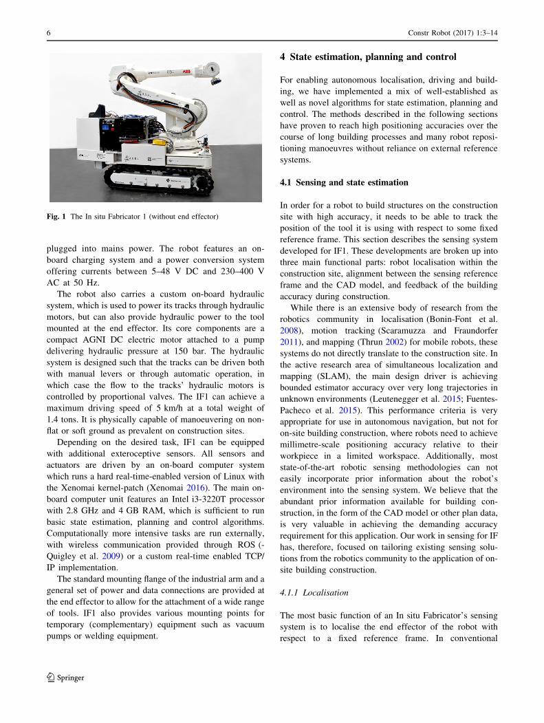
In 2014, the first prototype machine was realised, the IF1,
which is shown in Fig. 1. It is partially based on existing
parts from the Dimrob project Helm et al. (2012) and
mostly consists of commercially available off-the-shelf
components. A brief overview of the robot hardware is
given in the following section.
IF1 is equipped with an ABB IRB 4600 robot arm with
2.55 m reach and 40 kg payload. The decision to use an
industrial robot arm for the first prototype allowed for
quick progress in providing a fully sized mobile robot for
initial research, although its limitations were already
known at this point. All required industrial robot controller
electronics from an ABB IRC5 controller unit were fit to
the robot base in a custom, more compact form. The arm is
position-controlled, and a commercial control interface
provided by the manufacturer allows to send reference
position and velocity commands at 250 Hz rate.
IF1 is electrically powered. It carries four packs of
Li–Ion batteries with capacity for 3–4 h of autonomous
operation at average machine load without being
Constr Robot (2017) 1:3–14 5
123
plugged into mains power. The robot features an on-
board charging system and a power conversion system
offering currents between 5–48 V DC and 230–400 V
AC at 50 Hz.
The robot also carries a custom on-board hydraulic
system, which is used to power its tracks through hydraulic
motors, but can also provide hydraulic power to the tool
mounted at the end effector. Its core components are a
compact AGNI DC electric motor attached to a pump
delivering hydraulic pressure at 150 bar. The hydraulic
system is designed such that the tracks can be driven both
with manual levers or through automatic operation, in
which case the flow to the tracks’ hydraulic motors is
controlled by proportional valves. The IF1 can achieve a
maximum driving speed of 5 km/h at a total weight of
1.4 tons. It is physically capable of manoeuvering on non-
flat or soft ground as prevalent on construction sites.
Depending on the desired task, IF1 can be equipped
with additional exteroceptive sensors. All sensors and
actuators are driven by an on-board computer system
which runs a hard real-time-enabled version of Linux with
the Xenomai kernel-patch (Xenomai 2016). The main on-
board computer unit features an Intel i3-3220T processor
with 2.8 GHz and 4 GB RAM, which is sufficient to run
basic state estimation, planning and control algorithms.
Computationally more intensive tasks are run externally,
with wireless communication provided through ROS (-
Quigley et al. 2009) or a custom real-time enabled TCP/
IP implementation.
The standard mounting flange of the industrial arm and a
general set of power and data connections are provided at
the end effector to allow for the attachment of a wide range
of tools. IF1 also provides various mounting points for
temporary (complementary) equipment such as vacuum
pumps or welding equipment.
4 State estimation, planning and control
For enabling autonomous localisation, driving and build-
ing, we have implemented a mix of well-established as
well as novel algorithms for state estimation, planning and
control. The methods described in the following sections
have proven to reach high positioning accuracies over the
course of long building processes and many robot reposi-
tioning manoeuvres without reliance on external reference
systems.
4.1 Sensing and state estimation
In order for a robot to build structures on the construction
site with high accuracy, it needs to be able to track the
position of the tool it is using with respect to some fixed
reference frame. This section describes the sensing system
developed for IF1. These developments are broken up into
three main functional parts: robot localisation within the
construction site, alignment between the sensing reference
frame and the CAD model, and feedback of the building
accuracy during construction.
While there is an extensive body of research from the
robotics community in localisation (Bonin-Font et al.
2008), motion tracking (Scaramuzza and Fraundorfer
2011), and mapping (Thrun 2002) for mobile robots, these
systems do not directly translate to the construction site. In
the active research area of simultaneous localization and
mapping (SLAM), the main design driver is achieving
bounded estimator accuracy over very long trajectories in
unknown environments (Leutenegger et al. 2015; Fuentes-
Pacheco et al. 2015). This performance criteria is very
appropriate for use in autonomous navigation, but not for
on-site building construction, where robots need to achieve
millimetre-scale positioning accuracy relative to their
workpiece in a limited workspace. Additionally, most
state-of-the-art robotic sensing methodologies can not
easily incorporate prior information about the robot’s
environment into the sensing system. We believe that the
abundant prior information available for building con-
struction, in the form of the CAD model or other plan data,
is very valuable in achieving the demanding accuracy
requirement for this application. Our work in sensing for IF
has, therefore, focused on tailoring existing sensing solu-
tions from the robotics community to the application of on-
site building construction.
4.1.1 Localisation
The most basic function of an In situ Fabricator’s sensing
system is to localise the end effector of the robot with
respect to a fixed reference frame. In conventional
Fig. 1 The In situ Fabricator 1 (without end effector)
6 Constr Robot (2017) 1:3–14
123

industrial robots, this is easily achieved using the rotary
encoders in the robot’s joints since the robot is sufficiently
stiff and rigidly attached to the ground. For a mobile robot,
however, exteroceptive sensing is required to ensure zero-
drift pose estimates. A strategy typically used for such a
system is to track a known point on the robot with respect
to a static sensor system (e.g., a Vicon motion tracking
system or a Hilti Total Station). While these systems can
provide high-accuracy positioning data with minimal
integration effort, they can be prohibitively expensive and
take considerable initial setup time and effort. Furthermore,
the measurement frequency and delay is often not opti-
mized for mobile applications. Alternatively, sensors can
be mounted directly on the robot and used to locate visual
references in the robot’s workspace. While these solutions
are much lower cost, they typically require significantly
more integration effort, as the sensor information must be
heavily processed to extract the information required for
localisation (e.g., image processing to extract the local
visual features). This strategy is pursued for IF as to avoid
the presence of visibility constraints from an external
measurement system and because we believe this sensing
modality can be more easily expanded to feed back addi-
tional pieces of information to inform the remainder of the
building process (as in Sect. 4.1.3).
We have developed two separate sensing systems for
use on IF1, each supporting one of the application exam-
ples presented in Sect. 6. For the brick-laying experiments,
we mounted an off-the-shelf laser range finder (LRF) on
the end effector of IF1. By executing sweeping motions
with the wrist of the arm, we could build 3D point clouds
of the robot’s surroundings (Fig. 2). These point clouds
were then registered versus an initial point cloud to infer
the robot’s relative motion (see Dorfler et al. 2016 for
implementation details). The main shortcoming of this
method is that it assumes that the majority of the robot’s
environment remains unchanged during construction,
which is a bad assumption since construction sites are
constantly changing environments. Subsequent efforts
therefore focused on sensing modalities which allow the
robot to localise considering only measurements in vicinity
of its workpiece. In Sandy et al. (2016) we use the same
scanning system to build point clouds of the workpiece and
then register a geometric model of the workpiece to the
scan to determine the robot’s pose.
One of the disadvantages of using LRFs is that their
depth sensing accuracy and angular resolution are fixed by
the sensor’s internal hardware. This means that a sensor
used for mapping the robot’s environment is not well suited
for detecting small components of the workpiece. For the
Mesh Mould project (see Sect. 6.2) we therefore switched
to using camera-based sensing. Two camera systems are
used: one for global localization and one for local detection
of the wire mesh being built. We use the same model of
camera for both sensing tasks, but change the lens and
positioning of the cameras to address the different
requirements of the two sensing systems. For localisation,
two cameras fixed to the base of the robot observe
AprilTag (Olson and AprilTag 2011) fiducial markers to
localise relative to a calibrated map of the tag positions in
the workspace. With this system, we can achieve a global
positioning accuracy of less than 5 mm. This system alone
is not sufficient for construction of the mesh, though, since
the mesh deforms during construction due to internal ten-
sion in the wires. A second sensing system is therefore
required to measure the position of the wire used for the
next construction step so that the tool can clamp to it
without unexpected collisions. A stereo pair of cameras
mounted on the tool-head generates images of the mesh.
We then use line detection and matching, along with our
CAD model of the mesh, to locate the target wire. Figure 3
shows a stereo image pair from this system with the
detected wires highlighted. By coupling these two sensing
systems, we additionally obtain information as to how well
the measured mesh agrees with the original design.
4.1.2 Alignment with the CAD model
In most architectural applications, localising the tool with
respect to some general fixed global reference frame is not
Fig. 2 Point cloud of our lab captured by IF1
Fig. 3 Stereo image pair taken with the cameras on the Mesh Mould
toolhead during fabrication. The two detected wire segments are
highlighted in blue and red in each image. The next segment of the
mesh was welded to these segments
Constr Robot (2017) 1:3–14 7
123

enough. Any structure built needs to be attached to an
existing element of the construction site and must be
located with sufficient precision that the overall accuracy
of the construction is ensured. For in situ fabrication, this
can be achieved by aligning the sensing reference frame
with the reference frame of the CAD model of the structure
being built. This requires determining the position of either
the external sensing system or the visual features used for
localisation in the CAD model. This alignment step can
typically be done just once before building. During this
alignment step, key interfaces on the construction site, to
which the structure being build must attach, can be iden-
tified and their positions fed back to update the design of
the structure to accommodate any inaccuracies which may
be present on the construction site.
In the IF1 brick laying work (Sect. 6.1), localisation is
performed relative to a reference scan of the construction
site taken before starting to build. The reference scan is
aligned with the CAD model of the structure by registering
features of the constructions site to which the wall was
anchored (Fig. 4). In this way, the robot is not only able to
localise relative to the CAD model, but also we are able to
adjust the parametric design of the wall to match the true
positions of the pillars within the construction site. For the
Mesh Mould project (Sect. 6.2) we need to align our map
of the visual fiducial poses to the CAD model of the wall.
This is done by aligning the position of several reference
tags to their known positions in the CAD model.
4.1.3 Feedback of building accuracy
We believe that, to realise the full potential of robotic on-
site construction technology, the robot used should be able
to feed back data about the progress of the building project
during construction. In this way, building inaccuracies and
changing conditions in the construction site can be com-
pensated for during construction. This is especially crucial
in building processes where material does not behave
predictably after processing. This is the case in the Mesh
Mould project. As the wire mesh is constructed, internal
tension between the wires tends to pull the mesh away from
the position in which it was welded. The direction and
amount of deflection are difficult to model; therefore, real-
time feedback of the material behaviour is required to
ensure accurate construction. Using the two coupled mea-
surement systems described, however, IF can determine the
shape of the last wire welded to the mesh in the global
reference frame, therefore observing how well it matches
the initial design. In the presence of significant errors in the
wire contour, the building plan for the next layers of the
mesh can be adjusted to compensate for the error and
effectively pull the mesh back into alignment with the
CAD model. It should be noted that this functionality is a
natural extension of the camera sensing system since var-
ious custom features can be extracted from images rela-
tively easily. It would be very difficult, however, to do this
compensation if a commercial off-board sensing systems
was used, since it would not be capable of detecting the
contour of the wire mesh.
4.2 Planning and control
Generally speaking, we approach the planning and control
problem for In situ Fabricators through optimal control.
Optimal control solves the problem of finding a control
policy for a dynamic system such that a predefined crite-
rion of optimality is achieved. It can be used to compute
either open-loop trajectories, which is the domain of tra-
jectory optimisation, to compute feedback laws which
stabilise given trajectories, which is pure feedback control,
or both at the same time. By solving a corresponding
mathematical optimisation problem, we find optimal tra-
jectories and/or control laws that steer the system to a
desired pose while minimising some cost function and
respecting constraints at the same time. Difficulties arising
in planning and control for mobile construction robots are
obstacles, inherent motion constraints (for example non-
holonomic constraints due to wheels or tracks), motion
with contact and interaction forces and accumulated model
uncertainties. The latter is an important issue for IF1, as
tracked locomotion on imperfect ground can not be mod-
elled with high accuracy. In contrast to classical, sampling
based planning algorithms like Rapidly exploring random
trees and probabilistic roadmap methods (see LaValle 2006
for an overview), or the integrated kinematic planners
typically supplied with industrial robots, many optimal
control algorithms can handle some of these difficulties
with reasonable complexity.
For IF1, we have integrated different control and plan-
ning approaches, which allow us to consider base- and arm
motion either separately or jointly as a whole-body prob-
lem. Coordinated whole-body motions with non-holonomic
Fig. 4 Point cloud of the building site, showing the registered
positions of geometric models of the attachments pillars (red) and
floor (blue) of the CAD model
8 Constr Robot (2017) 1:3–14
123

base constraints and holonomic operational-space con-
straints (e.g. tool position constraints) are generated using
constrained sequential linear quadratic (SLQ) optimal
control. Although being an iterative optimal control algo-
rithm, it is computationally highly efficient, as it features
linear time complexity O(n). Feedforward trajectories and
feedback are optimised simultaneously, which generalises
the control policy in the vicinity of the nominal, optimal
trajectory. The resulting feedback gains are compliant with
non-holonomic constraints. On IF1, we run this algorithm
in a model predictive control (MPC) fashion at up to
100 Hz update rate, where the feedback loop is closed
through an on-board visual–inertial state estimator. This
allows us to achieve robust positioning despite the presence
of model uncertainties and external perturbations. In par-
ticular, this allows for rejecting uncertainty from the
tracked locomotion from the end effector motion. Figure 5
shows snapshots from a motion sequence with an end
effector position constraint executed on IF1 using Con-
strained SLQ in an MPC fashion. More details about SLQ
MPC on IF1 and experimental results are provided
in Giftthaler et al. (2017).
When performing sequential building tasks, as for
example demonstrated in Sandy et al. (2016), or when
more obstacles are present, we separate the base- and arm
control problem and move base and arm sequentially. In
this case, we use a constrained version of the stochastic
planner STOMP Kalakrishnan et al. (2011, 2013) for tra-
jectory optimisation and a simple trajectory following
strategy as presented in Sarkar et al. (1993).
For manipulation, we combine individually planned
sequences of arm/base motion with a library of task-
specific, pre-programmed manipulation primitives (e.g.,
picking up a brick from the brick feeder or moving a joint
at constant velocity). This combination has proven suffi-
cient for a number of building tasks.
Note that our approach can typically handle a moderate
number of convex obstacles easily and reliably. However,
at the current stage, we cannot handle cluttered or frag-
mented environments with a large number of non-convex,
possibly intersecting or dynamically changing obstacles.
Besides requiring a system for real-time obstacle percep-
tion and classification, which is currently not implemented,
this would lead to strongly non-convex and ill-posed
optimisation problems which cannot be treated in a clas-
sical optimal control setting. The combination of our
optimal control framework with higher-level planners
which are able to negotiate cluttered environments is part
of our future research.
5 Integration into architectural designand planning software
A major interest in the development of the In situ Fabri-
cator is to tightly integrate its functions and capabilities
into an architectural planning framework, to make its fea-
tures directly available for architects and designers.
Eventually we are aiming to see the generation and
rationalisation of shapes to be directly influenced by the
specific logic of making—in this case, next to the choice of
a material and assembly system, this is the feature of
mobility and the extended workspace of the mobile robot.
To fully exploit the design-related potentials of using
such a robot for fabrication, it is essential to make use not
only of the manipulation skills of this robot, but to also use
the possibility to feed back its sensing data into the design
environment. This allows the system to guide and inform a
running fabrication process such as to be able to detect and
react upon unforeseen assembly tolerances and process-
related uncertainties. Furthermore, the system can base
immediate design decisions on the information extracted
from sensors, allowing a high level of flexibility, autonomy
and control in fabricating an architectural artifact.
Motivated by this, the high level planning of fabrication
tasks, such as the sequencing of the mobile robot’s posi-
tions and fabrication procedures and computing the arm,
base and end effector positioning commands, is imple-
mented within an architectural planning tool, in our case
Grasshopper Rhinoceros (Rhinoceros 2016). A TCP/IP
plugin allows for the online control the robot’s arm and
base, and gives access to the robot’s state estimator,
planning routines and movement primitives. This approach
is also detailed in Dorfler et al. (2016) and Kumar et al.
(2017). Generally speaking, the robot’s setup is designed to
allow for feedback loops at multiple levels of the system:
Fig. 5 Snapshots from a motion sequence with an end effector
position constraint executed on IF1 using Constrained sequential
linear quadratic optimal control in a model predictive control fashion.
The task is to reposition and reorient the base while keeping the end
effector at a constant position
Constr Robot (2017) 1:3–14 9
123

all time-sensitive tasks are executed by control loops run-
ning on the robot’s low-level computer while the control
loop over the overall building process is closed via the
architectural planning tool.
6 Architectural demonstrators and examples
The main drivers for the development of the IF1’s func-
tionality and software framework were the architectural
demonstrators shown in this section. The challenge of
fabricating multiple architectural prototypes with an
increasing level of complexity was specifically chosen to
gradually advance the generic features of the robot. The
realisation of these demonstrators was significant for
evaluating chosen methods and to learn what is neces-
sary—from both the robotics and the architecture point of
view—to enable automated material deposition and
assembly processes in an unstructured, cluttered, and ever
changing environment such as a construction site. At the
current stage of development, this enables us to build
customised, geometrically complex structures accurately
over the course of the entire building space. While the
presented experiments are still performed on flat ground, a
generalization onto non-flat surfaces would be possible.
6.1 Undulating brick wall
The first architectural scale demonstration with IF1 was
the semi-autonomous fabrication of a continuous dry-
stacked, undulating brick wall (Fig. 6) in a laboratory
environment which was set-up to mimic a construction site.
The material system—consisting of discrete building ele-
ments and a simple assembly logic—allowed us to subdi-
vide the sequential building process of the entire wall into
discrete production steps from subsequent robot locations
(Fig. 7).
In this experiment, it played a key role to align the CAD
model of the building site with the true positions of key
features of the working environment, extrapolated from the
initial 3D scan of the surrounding captured by the robot’s
sensor system. This allowed us to adapt the ideal dimen-
sions of the wall’s parametric geometry model to the true
dimensions of the construction site before actually starting
the fabrication.
The building process itself consisted of iterative steps of
moving the robot to positions along the wall, localising the
robot’s base pose and building a patch of bricks reachable
within the workspace of the robot. The global localisation
and brick placement errors did not accumulate over the
course of the building process, first because of the initial
alignment of the true positions of the attachment points to
the building plan, and second, every point cloud for
localisation captured from a new location was always
registered against the same initial reference scan. There-
fore, the designed double-leaf brick wall—requiring the
robot to be repositioned 14 times—was successfully con-
structed semi-autonomously with a maximal assembly
error of 7 mm over the entire workpiece. While the
bricklaying was done autonomously, feeding the robot with
bricks was accomplished manually.
6.2 Mesh mould
The second demonstrator combines the novel construction
technique Mesh Mould (Hack et al. 2015; Kumar et al.
2017) with the use of IF1. The main objective of Mesh
Mould is the bespoke fabrication of free-form steel meshes
which form both mould and reinforcement to enable a
waste-free production of customised reinforced concrete
wall structures (see Fig. 8). This fabrication method is an
ideal test-bed for showing the possibility of a continuous
construction process fabricated by a mobile robot. The
possibility to bend and weld these meshes directly on site
offers a multitude of advantages: the integrated vision
feedback system allows to react to material tolerances
during fabrication on the spot: It allows to negotiateFig. 6 IF1 building the undulating brick wall
Fig. 7 Visualisation of a possible building sequence for the double-
leaf brick wall shown in Fig. 6. The wall is 6.5 m long and 2 m high,
consists of 1600 bricks and is fabricated from 15 different base
positions
10 Constr Robot (2017) 1:3–14
123

between true measurements of the structure during build-
up and a required target shape based on the planning data
right when it is needed. Production sequences can radically
be redefined: Structures to be built do not have to be dis-
cretised into separate building components due to size
limits for transportation, but can rather be redefined in
accordance with the fabrication logics of the chosen
material system and the mobile machinery.
The integration of the robotised Mesh Mould end
effector for bending and welding steel wires into the
architectural control and simulation framework of IF1
constituted a major part of the efforts in implementation.
Once completed, the whole system was tested for the first
time on a floor slab of NEST1—an exploratory construction
site at EMPA in Zurich. The fabrication of an undulated,
curved Mesh Mould element directly on the construction
site served to test the system’s robustness under realistic
working conditions and helped to understand the logistics
requirements of performing the fabrication process in situ
(see Fig. 9). For more details, the interested reader may
also refer to Hack et al. (2017).
For the Mesh Mould project, IF1 was equipped with
both a global and local state estimator (see Fig. 10). The
global pose estimation of the robot’s origin using artificial
landmarks enables automated localisation during reposi-
tioning procedures. Further, the integration of perception at
the end effector is required for correcting its pose in case of
detecting accumulative fabrication errors and mesh
deformations.
Currently IF1 and Mesh Mould are integrated into a
larger building project: a fully load bearing 14 m long steel
reinforced concrete wall is being fabricated at the ground
level of the NEST unit realized by the Swiss National
Competence Center of Research in Digital Fabrication.2
7 Limitations and lessons learned from IF1: whyclassical industrial arms are a poor choicefor mobile building construction robots
IF1 by design exhibits a number of drawbacks. Impor-
tantly, these shortcomings are not specific to this particular
robot, but are rather inherent to the relevant off-the-shelf
technology existing to date and being available to research
in our field. Some of the predominant issues are sum-
marised in the following section.
Standard serial-chain industrial manipulators often make
use of heavy-duty electric motors and gearboxes. The joints
and links are designed for maximising stiffness, which is
essential for reaching high positioning accuracy using tra-
ditional robot control approaches. A consequence resulting
from that design strategy is a relatively low payload to
Fig. 8 Mesh Mould demonstrators built by IF1
Fig. 10 Vision system and frame definition for the Mesh Mould wall
fabrication process: 1 world frame, 2 tag frame, 3 robot frame, 4 base
camera frame, 5 end effector frame, 6 end effector camera frame
Fig. 9 IF1 building a small doubly curved metal mesh at the
exploratory construction site NEST
1 https://www.empa.ch/web/nest. 2 http://www.dfab.ch
Constr Robot (2017) 1:3–14 11
123

weight ratio (PWR). For example, our ABB IRB 4600 arm
offers a PWR of 40:440 kg. Additional downsides to the
weight of industrial robots are the need for a heavy base to
ensure that the robot cannot tip over, the difficulty trans-
porting the robot, and the added safety risks of operating
such a large system. At 1.4 tons, IF1 is already too heavy to
access some standard building environments.
Purely position-controlled robotic arms are by design ill-
suited for many construction tasks. For advanced manipu-
lation tasks taking place beyond perfect conditions, such as
on-site assembly of structures, drilling, coring or chiseling,
being able to control the interaction forces between tool
and workpiece is essential. While adding a multi-DoF
force–torque sensor at the end effector appears to be a
workaround and certainly gives more flexibility to the
setup, it remains a sub-optimal design choice. While a
detailed discussion of this issue is beyond the scope of this
paper, it is a well established result that such an arrange-
ment (non-collocated sensing and control) has non-ideal
control theoretical stability properties. This practically
restricts the system to slow, conservative motions, and
imposes strong limitations on the dynamics of processes
that can be controlled by the end effector. For a detailed
treatment of the drawbacks of non-collocated force control,
we refer to Eppinger and Seering (1986, 1987), Howard
(1990).
Moreover, for many of the aforementioned tasks, clas-
sical, electrically actuated robot arms without compliant,
vibration-damping mechanical elements will not be suited
for long runtimes and everyday application. Bad load cases
can rapidly damage sensitive mechanical elements such as
gearboxes and will cause them to wear out rapidly. In
robotics, common solutions are to consider series-elastic or
hydraulic actuators.
Consequently, the next-generation In situ Fabricator
needed to be thoroughly rethought to provide a concept
which resolves these problems. It’s worth mentioning that
sufficiently sized platforms with full force–torque control
at joint level, and access to low-level control loops (for
implementing dynamically capable control methods) are
commercially not available today.
8 Developing the next-generation In situFabricator
From the experience gained with IF1 and the Mesh Mould
project, it is clear that the next-generation In situ Fabricator
(IF2) has to fulfil an additional set of requirements:
– Agility Able to perform a specified set of manoeuvres
typical of operating in a representative building, for
example traverse a narrow doorway from a corridor.
– Payload Capable of operating with a 60 kg payload.
– System weight Maximum of 440 kg overall system
weight (500 kg including payload), which corresponds
to a typical maximum load for a standard floor.
– Arm(s) at least one 7 DOF robotic arm with at least 2.5
m reach.
– Safety Capable of reverting to safe or passive modes on
detection of an unsafe situation.
– Robust in construction site Minimise or eliminate
external components that may be subject to damage,
e.g. external hoses and wires. Maximise reliability and
on-site maintainability.
– Control Capable of high bandwidth ([1 kHz) force and
position control.
Through straight-forward calculations, it can be shown that
using conventional electrical or hydraulic robot joint
actuators, it would be impossible to achieve the required
440 kg overall mass limit and the desired PWR at the same
time. An assessment of the other system requirements
suggests that a completely novel actuator design is required
to achieve the desired performance, weight and force
control properties.
8.1 Intermediate result: development of a novel type
of hydraulic actuator
To meet the demanding requirements for IF2, a highly
feature dense, structurally capable, lightweight actuator
design is required. In cooperation with Moog Inc and
Renishaw PLC, we are developing a novel, integrated
hydraulic actuator offering superior power density. Build-
ing on previous work in the field of integrated actua-
tion (Fig. 11), a novel titanium fully integrated vane
actuator is developed (see Fig. 12). The actuator is con-
structed around a conventional limited angle rotary vane
actuator and includes all hydraulic controls, safety valves,
sensors, electronic controls, local processing, data bus as
well as hydraulic and electrical slip rings. To provide the
required degree of integration in a compact, structurally
efficient package, additive manufacturing using the laser
powder bed principle was chosen for the major
components.
The actuator is capable of mounting for joint rotation
around and perpendicular to the major axis. It is designed
in three different sizes, which for example allows for a
lightweight realisation of different manipulator segments
such as arms or legs.
8.2 Outlook on IF2
Hydraulic actuation in conjunction with advanced addi-
tive manufacturing technology is particularly well suited
12 Constr Robot (2017) 1:3–14
123

to construction robots. It features superior power density,
even on compact, mobile systems with on-board pumps.
At the same time, hydraulic systems can be scaled up to
dimensions relevant for construction machinery more
easily than electrically actuated systems and are typi-
cally highly robust—one of the reasons why a majority
of heavy-duty machinery on today’s construction site is
hydraulically driven.
Based on our experience with IF1 and the novel hydraulic
actuators, a preliminary design of IF2 has been created,
which is shown in Fig. 13. To achieve the desired manoeu-
vrability, it is equipped with legs and wheels, which allows
for multiple modes of locomotion: walking, driving, or
hybrid modes. Amain design goal of IF2 is modularity, such
that the robot’s morphology can be adapted to different
requirements of different architectural tasks with compara-
bly low effort. IF2 is currently under development. The
overall design shown in Fig. 13 represents the current con-
cept, its feasibility is pending on how further tests with the
novel actuators evolve. Prototypes of the hydraulic actuators,
a first arm prototype, as well as first experimental results are
expected by the end of 2017.
9 Summary and conclusion
In this paper, motivated by the need for digitally controlled
mobile robots for on-site manufacturing, assembly and
digital fabrication, we have presented an overview of a
class of machine that we call ‘In situ Fabricators’. We have
listed the core requirements defining that class of robot. We
have presented a compact overview of the IF1, which is a
prototype system based on classical industrial off-the-shelf
components, and its capabilities. To meet the desired
accuracy and performance, we have implemented a number
of state-of-the-art algorithms for motion planning, state
estimation and control. The development and implemen-
tation of the IF1’s software framework was strongly
inspired by the needs of two full-scale application
demonstrators, which are showcased in this paper: First, a
full-size undulating brick wall, which required a number of
repositioning manoeuvres during the building process, in
which we achieved mm-scale positioning accuracy. Sec-
ond, the Mesh Mould process, which shows that an In situ
Fabricator in combination with an innovative toolhead can
be used to enable completely novel building processes. IF1
successfully built a number of metal mesh segments, which
were also filled with concrete and underwent structural
load tests. In a next step, IF1 will be deployed to an
exploratory construction site to build the ground floor of a
demonstrator living unit.
We also emphasised the limitations of our approach. As
the general interest in construction robotics and digital
fabrication is currently increasing in both academia and
industry, one of our core aims is to raise the awareness
amongst other researchers in the field, that the classical
industrial robotics approach is bound to a number of sig-
nificant disadvantages. In our case, these limitations pro-
vided the motivation for the development of an innovative,
compact, force-controlled rotary hydraulic actuator.
Fig. 11 Linear integrated actuator, see Semini et al. (2016) for
details
Fig. 12 Section through a fully integrated vane actuator as described
in Sect. 8. It includes all hydraulic controls, sensors, electronics, local
processing, data bus and slip rings
Fig. 13 Concept of the In situ Fabricator 2, which is currently under
development
Constr Robot (2017) 1:3–14 13
123

Thanks to very recent developments in AM technology we
are enabled to use highly integrated compact actuators in
conjunction with very efficient additively manufactured
structural components. We concluded this work by intro-
ducing the concept for IF2, the next-generation In situ
Fabricator. We expect that this development is going to be
a major step towards facilitating advances in full-scale
construction robots.
References
Andres J, Bock T, Gebhart F (1994) First results of the development
of the masonry robot system ROCCO. In: Proceedings of the
11th ISARC in Brighton (international symposium on automa-
tion and robotics in construction), pp 87–93
Ardiny H, Witwicki SJ, Mondada F (2015) Are autonomous mobile
robots able to take over construction? A review. Int J Robot
4(3):10–21
Bonin-Font F, Ortiz A, Oliver G (2008) Visual navigation for mobile
robots: a survey. J Intell Robot Syst 53(3):263–296
Bosscher P, Williams RL, Bryson LS, Castro-Lacouture D (2007)
Cable-suspended robotic contour crafting system. Autom Constr
17(1):45–55
Dorfler K, Sandy T, Giftthaler M, Gramazio F, Kohler M, Buchli, J
(2016) Mobile robotic brickwork—automation of a discrete
robotic fabrication process using an autonomous mobile robot.
In: Robotic fabrication in architecture, art and design,
pp 205–217
Eppinger S, Seering W (1986) On dynamic models of robot force
control. In: IEEE international conference on robotics and
automation (ICRA), vol 3, pp 29–34
Eppinger S, Seering W (1987) Understanding bandwidth limitations
in robot force control. In: IEEE international conference on
robotics and automation (ICRA), vol 4, pp 904–909
Fuentes-Pacheco J, Ruiz-Ascencio J, Rendon-Mancha JM (2015)
Visual simultaneous localization and mapping: a survey. Artif
Intell Rev 43:55–81
Giftthaler M, Farshidian F, Sandy T, Stadelmann L, Buchli J (2017)
Efficient kinematic planning for mobile manipulators with non-
holonomic constraints using optimal control. In: IEEE interna-
tional conference on robotics and automation (ICRA)
Hack N, Lauer WV, Gramazio F, Kohler M (2015) Mesh Mould:
robotically fabricated metal meshes as concrete formwork and
reinforcement. In: FERRO-11: proceedings of the 11th interna-
tional symposium on ferrocement and 3rd ICTRC international
conference on textile reinforced concrete. RILEM Publications
SARL, Bagneux, pp 347–359
Hack N, Wangler T, Mata-Falcon J, Dorfler K, Kumar N, Walzer A,
Graser K, Reiter L, Richner H, Buchli J, Kaufmann W, Flatt RJ,
Gramazio F, Kohler M (2017) Mesh Mould: an on site,
robotically fabricated, functional formwork. In: Concrete inno-
vation conference HPC/CIC. Tromsø
Helm V, Ercan S, Gramazio F, Kohler M (2012) Mobile robotic
fabrication on construction sites: Dimrob. In: 2012 IEEE/RSJ
international conference on intelligent robots and systems
(IROS)
Howard RD (1990) Joint and actuator design for enhanced stability in
robotic force control. Ph.D. thesis, Massachusetts Institute of
Technology
Jokic S, Novikov P, Maggs S, Sadan D, Jin S, Nan C (2015)
Minibuilders. In: Architectural principles, tools, and processes.
Digital Vernaclar, pp 259–265
Kalakrishnan M, Chitta S, Theodorou E, Pastor P, Schaal S (2011)
Stomp: stochastic trajectory optimization for motion planning.
In: IEEE international conference on robotics and automation
(ICRA), pp 4569–4574
Kalakrishnan M, Herzog A, Righetti L, Schaal S (2013) Markov
random fields for stochastic trajectory optimization and learning
with constraints. In: Robotics: science and systems, workshop on
hierarchical and structured learning for robotics, Berlin
Keating S (2016) From bacteria to buildings: additive manufacturing
outside the box. Ph.D. thesis, Massachusetts Institute of
Technology
Khoshnevis B (2004) Automated construction by contour craftingre-
lated robotics and information technologies. Autom Constr
13(1):5–19
Kumar N, Hack N, Dorfler K, Walzer A, Rey G, Gramazio F, Kohler
M, Buchli J (2017) Design, development and experimental
assessment of a robotic end-effector for non-standard concrete
applications. In: IEEE international conference on robotics and
automation (ICRA) (submitted)LaValle SM (2006) Planning algorithms. Cambridge University
Press, Cambridge
Leutenegger S, Lynen S, Bosse M, Siegwart R, Furgale P (2015)
Keyframe-based visual-inertial odometry using nonlinear opti-
mization. Int J Robot Res 34(3):314–334
Olson E (2011) AprilTag: a robust and flexible visual fiducial system.
In: Proceedings of the IEEE international conference on robotics
and automation (ICRA). IEEE, pp 3400–3407
Pritschow G, Dalacker M, Kurz J, Gaenssle M (1996) Technological
aspects in the development of a mobile bricklaying robot. Autom
Constr 5(1):3–13
Quigley M, Conley K, Gerkey BP, Faust J, Foote T, Leibs J, Wheeler
R, Ng AY (2009) Ros: an open-source robot operating system.
In: ICRA workshop on open source software
Rhinoceros G (2016) Grasshopper Rhinoceros. http://www.grass
hopper3d.com/. Accessed 06 Nov 2016 (Online)Sandy T, Giftthaler M, Dorfler K, Kohler M, Buchli J (2016)
Autonomous repositioning and localization of an in situ fabri-
cator. In: IEEE international conference on robotics and
automation (ICRA), pp 2852–2858
Sarkar N, Yun X, Kumar V (1993) Dynamic path following: a new
control algorithm for mobile robots. In: Decision and control,
1993. Proceedings of the 32nd IEEE conference, vol 3,
pp 2670–2675. doi:10.1109/CDC.1993.325681
Scaramuzza D, Fraundorfer F (2011) Visual odometry [tutorial].
IEEE Robot Autom Mag 18(4):80–92
Semini C, Baker M, Laxman K, Chandan V, Maruthiram T, Robert
Morgan R, Frigerio M, Barasuol V, Caldwell DG, Rey G (2016)
A brief overview of a novel, highly-integrated hydraulic servo
actuator with additive-manufactured titanium body. In: IEEE/
RSJ IROS workshop on force/torque controlled actuation
Thrun S et al (2002) Robotic mapping: a survey. Exploring artificial
intelligence in the new millennium, vol 1, pp 1–35
Willmann J, Knauss M, Bonwetsch T, Apolinarska AA, Gramazio F,
Kohler M (2016) Robotic timber construction expanding addi-
tive fabrication to new dimensions. Autom Constr 61:16–23
Xenomai (2016) Xenomai: real-time framework for Linux. http://
www.xenomai.org. Accessed 06 Nov 2016 (Online)
14 Constr Robot (2017) 1:3–14
123