![Uterine artery blood flow, fetal hypoxia and fetal growth · approximately 800 ml min21 bilateral UtA blood flow (270 ml min 21kg newborn weight) is required [20]. (c) Importance](https://static.fdocuments.us/doc/165x107/5d49918488c993e10e8b9228/uterine-artery-blood-flow-fetal-hypoxia-and-fetal-growth-approximately-800.jpg)
ML 800 Series Laser - Industrial Fiber Optics, Inci-fiberoptics.com/pdf/12_0098-ml8xxseries.pdf ·...
24
INDUSTRIAL FIBER OPTICS Model Numbers: ML 800 ML 810 ML 868 ML 869 ML 869A ML 800 Series Laser Hard-Seal Helium Neon Operator’s Manual
Transcript of ML 800 Series Laser - Industrial Fiber Optics, Inci-fiberoptics.com/pdf/12_0098-ml8xxseries.pdf ·...

IndustrIal FIber OptIcs
Model Numbers: ML 800 ML 810 ML 868 ML 869 ML 869A
ML 800 Series LaserHard-Seal Helium Neon
Operator’s Manual

*
Copyright © 2017Previous printings 2008, 2009 and 2013
by Industrial Fiber Optics, Inc.Revision - H
Printed in the United States of America
* * *
All rights reserved. No part of this publication may be reproduced,stored in a retrieval system, or transmitted in any form or by any means
(electronic, mechanical, photocopying, recording, or otherwise)without prior written permission from Industrial Fiber Optics.
* * * * *

– i –
INTRODUCTION
This manual provides information about the family of Hard-Seal Helium Neon Lasers that formerly were manufactured by Metrologic, Inc. It contains all the information needed to set up and operate these lasers safely and knowledgeably, even if you are a novice to laser technology. Please read the manual carefully before operating the laser.
Industrial Fiber Optics makes every effort to incorporate state-of-the-art technology, highest quality and dependability in its products. We constantly explore new ideas and products to best serve the rapidly expanding needs of industry and education. We encourage comments that you may have about our products, and we welcome the opportunity to discuss new ideas that may better serve your needs. For more information about our company and products refer to www.i-fiberoptics.com on the Internet.
Thank you for selecting this Industrial Fiber Optics product. We hope it meets your expectations and provides many hours of productive activity.
Sincerely,
The Industrial Fiber Optics Team

– ii –
.

– iii –
TABLE OF CONTENTSIntroduction……………………….................…….....…………..…… iLASER CLASSIFICATION.........….............................……..…...… ivGENERAL…………................….............................……..…...…….. 1SAFETY NOTES.............................................................................. 2 Laser Safety.................................................................................... 2 Electrical Safety.............................................................................. 3 CDRH Regulations.......................................................................... 3OPERATING CONDITIONS…....................………..................……. 4 Input Voltage.................................................................................. 4 Environmental Limits...................................................................... 4LASER SPECIFICATIONS.............................................................. 5LASER OPERATION....................................................................... 6 Beam Controls............................................................................... 6 Power Controls.............................................................................. 6 Operating Instructions................................................................... 7TROUBLESHOOTING..................................................................... 7MODULATED LASERS (ML 868, ML 869, ML 869A).............................. 8 Connectors for Signal Input........................................................... 8 Modulation Characteristics............................................................ 8 Detectors....................................................................................... 8 Troubleshooting for Modulated Lasers.......................................... 9APPLICATIONS AND DEMONSTRATIONS.................................... 10 Optical Galvanometer.................................................................... 10 Diffraction, Variable Slit................................................................. 10 Laser Light Show........................................................................... 11 Index of Refraction, Liquids........................................................... 11 Interference, Evaporation of Alcohol.............................................. 11WARRANTY..................................................................................... 12SHIPMENT DAMAGE CLAIMS....................................................... 13SERVICE AND MAINTENANCE...................................................... 14TABLE 1. COMMON ABBREVIATIONS.......................................... 15

– iv –
LASER CLASSIFICATIONSAll manufacturers of lasers used in the United States must conform to regulations administered by the Center for Devices and Radiological Health (CDRH), a branch of the U.S. Department of Health and Human Services. CDRH categorizes lasers as follows:
Class Description
I A laser or laser system, which does not present a hazard to skin or eyes for any wavelength or exposure time. Exposure varies with wavelength. For ultraviolet, 2 to 4 µm exposures is less than from 8 nW to 8 µW. Visible light exposure varies from 4 µW to 200 µW, and for near-IR, the exposure is < 200 µW. Consult CDRH regulations for specific information.
II Any visible laser with an output less than 1 mW of power. Warning label requirements – yellow caution label stating maximum output of 1 mW. Generally used as classroom lab lasers, supermarket scanners and laser pointers
IIIa Any visible laser with an output over 1 mW of power with a maximum output of 5 mW of power. Warning label requirements – red danger label stating maximum output of 5 mW. Also used as classroom lab lasers, in holography, laser pointers, leveling instruments, measuring devices and alignment equipment.
IIIb Any laser with an output over 5 mW of power with a maximum output of 500 mW of power and all invisible lasers with an output up to 400 mW. Warning label requirements – red danger label stating maximum output. These lasers also require a key switch for operation and a 3.5-second delay when the laser is turned on. Used in many of the same applications as the Class IIIa when more power is required.
IV Any laser with an output over 500 mW of power. Warning label requirements – red danger label stating maximum output. These lasers are primarily used in industrial applications such as tooling, machining, cutting and welding. Most medical laser applications also require these high-powered lasers.

– 1 –
GENERAL In the ML 800 Series, Industrial Fiber Optics offers lasers in a range of power, size and price. The helium neon tubes used in these lasers have a shelf life of at least 10 years, and a lifespan of at least 20,000 hours of continuous operation.
Recommended uses of the different lasers are listed below:
ML 800 Student Use, Demonstrations
ML 810 Student Use, Holography
ML 868 Lecture Demos, Modulation, Voice or Video Communication
ML 869 Lecture Demos, Modulation, Voice or Video Communication, Holography, Research
ML 869A Lecture Demos, Modulation, Voice Communication, Holography, Research
This manual contains information on laser specification, operation, safety and trouble-shooting. The manual includes experiments that can be conducted with the laser. Many ideas for additional activities and investigations can be found on our website, www.i-fiberoptics.com. Look for the Laser Teaching Supplements on the website. Additionally, the following complete projects/labs (and many others) can be purchased from Industrial Fiber Optics for use with the laser:
Laser Optics Lab This lab contains more than 30 optical parts and accessories. These tools can be used to demonstrate the principles of optics in a basic course of physics or physical science.
Physical Optics Lab With this lab, image processing and Fourier transforms of optical formations can be practical studies for high schools and undergraduate physics classes.
Michelson Interferometer This is a classic device for splitting a beam of monochromatic light into two parts that travel along different optical paths and then merge again to produce interference fringes.
Modern Laser Optics Kit This innovative collection of nine unique optical mounts offers endless possibilities for exploring the many aspects of modern optical technology.
Laser Audio Receiver This lab contains a microphone and audio receiver, along with the instructions needed to turn your modulated laser into a free-air voice communication link.
Check the website www.i-fiberoptics.com for details.
45-600
45-688
45-940
IF 535
IF LSL2

– 2 –
SAFETY NOTESLaser SafetyLasers are valuable sources of light for conducting exciting demonstrations and laboratory experiments in schools.
Industrial Fiber Optics lasers emit a beam of visible light. However, they do not emit invisible, exotic, or otherwise harmful radiations. See page iv for LASER CLASSIFICATIONS.
Industrial Fiber Optics lasers are low-power lasers. The light output is only a few milliwatts, i.e., a few thousandths of a watt. These lasers should not be confused with the powerful lasers intended for burning, cutting and drilling.
Although the power of Industrial Fiber Optics lasers is low, treat all laser beams with caution and common sense because they are intense and concentrated. The greatest potential for harm with Industrial Fiber Optics lasers is to the eyes. Just as no one should stare at the sun or arc lamps, no one should look directly into the laser beam or stare at its bright reflections.
The United States Center for Devices and Radiological Health (CDRH) regulates manufacturers of lasers to ensure that users are not endangered. The federal government classifies lasers according to their power levels and specifies appropriate safety features for each level. Demonstration lasers fall into Class II and they can be identified by a yellow “Caution” label that contains the warning, “Do not stare into beam.” Class II lasers have a maximum power of 0.95 milliwatt, i.e., 1/1000th of a watt. They conclude that the power is eye-safe, except possibly in the case of deliberate, long-term direct staring into the beam. Safety features include a pilot lamp, which glows when the electrical power is on, and a mechanical beam stop, which can block the beam when the power is on.
The following are labels located on helium-neon lasers:
Hard-Seal LaserPeriodic operation not required
Figure 1. Laser labels.
CAUT IONLASER RADIATION
DO NOT STARE INTO BEAM
PEAK POWER 1 mWWAVELENGTH 600 - 700 nm
Class II Laser Product
1189.eps
LASER RADIATIONDO NOT STARE INTO BEAM
PEAK POWER 5 mWWAVELENGTH 600 - 700 nm
Class IIIa Laser Product
DANGER
1190.eps
CAUTION!Plug laser only intogrounded outlets
1533.eps

– 3 –
What steps can be taken to practice safety?
1. NEVER aim the laser beam directly into your eyes or the eyes of anyone else.
2. Block off laser beams so they cannot extend beyond the limits of individual laboratory stations. Use dull, non-reflective objects such as dark-colored paper or stacks of books.
3. If the beam must travel a long distance, keep it close to the floor or keep it sufficiently high so it does not cross walkways at eye level.
4. Cover or remove any wall mirrors or other bright objects that could reflect a concentrated laser beam into anyone’s eyes.
Electrical SafetyHelium-neon lasers employ high voltages similar to that inside a small television receiver. Capacitors within the power supply retain the potentially harmful voltage for periods after the input power has ceased. To protect the user and to comply with federal laser safety legislation, Industrial Fiber Optics seals the laser housing. Never open the housing. If the housing is opened, Industrial Fiber Optics’ product warranty will be voided.
Each laser is equipped with a UL-approved line cord and three-prong grounded plug.
ALWAYS PLUG THE LASER INTO A GROUNDED OUTLET.
CDRH RegulationsAll Industrial Fiber Optics’ lasers comply with the Laser Performance Standard of the U.S. Department of Health and Human Resources. They also comply with Title 21, Part 1040 of the Code of Federal Regulations as it applies on the date of manufacture. These regulations classify lasers by beam power and specify safety features.
The ML 800, 810, and 868 are classified as Class II lasers and have a maximum radiant power of 0.95 mW. Class II lasers must contain a pilot light, mechanical beam shut-off and the Caution label.
The ML 869 and ML 869A are classified as Class IIIa lasers and have a maximum radiant power of 5 mW.

– 4 –
Besides the CDRH label, each laser has the following label placed near the beam exit: “Avoid exposure. Laser light is emitted from this aperture.” The CDRH also requires that manufacturers provide users with the following information: “Caution – Use of controls or adjustments or performance of procedures other than those specified herein may result in hazardous light exposure.” The fourth label identifies Industrial Fiber Optics as the manufacturer, states the model and serial numbers and certifies that the laser has been manufactured to meet the Laser Performance Standard.
This is an example of the Model Number Label:
Lasers manufactured for export are not certified with respect to the U.S. Laser Performance Standard.
For further information on federal laser safety rules, contact the U.S. Food and Drug Administration Center for Devices and Radiological Health, 8757 Georgia Ave., Silver Springs, MD 20910 or the Laser Institute of America 1350 Ingenuity Dr., Suite 128, Orlando, FL 32826.
OPERATING CONDITIONSInput VoltageThe input voltage range of the laser power supply is listed on the label that specifies model and serial number. Each power supply design is to function at either of the following ranges: 105 -125 VAC or 210 – 250 VAC with an external step-down transformer. All lasers will operate between 45 and 1000 Hz. Neither the laser tube nor the power supply are warranted for operation outside these limits.
Environmental LimitsThe laser and power supply is designed to operate at temperatures ranging from -20 C to +50 C, at altitudes to 3,000 meters and at humidity to 99 percent without condensation.
Figure 2. Model number label.

– 5 –
LASER SPECIFICATIONS
Model Power (mW) Beam Diameter Divergence Housing Class
# Min. Typ. Max. in mm (1-1/e²) (mRad)
L x W x H
(mm)
ML 800 0.3 0.5 0.95 0.48 1.7 239 x 72 x 74 II
ML 810 0.6 0.8 0.95 0.48 1.7 239 x 72 x 74 II
ML 868 0.6 0.8 0.95 0.66 1.25 328 x 72 x 74 II
ML 869 1.0 1.5 2.9 0.66 1.25 328 x 72 x 74 IIIa
ML 869A 1.1 2.0 3.5 0.49 1.65 328 x 72 x 74 IIIa
All of Industrial Fiber Optics’ ML 800 series of lasers are of hard-seal construction.
“Hard-seal” means the mirrors are fused to the tube body and it does not require periodic operation.
The ML 868, ML 869 and ML 869A are modulated lasers.
All specifications are subject to change without notice.

– 6 –
LASER OPERATIONBeam ControlsThe only moving parts at the front end of the laser are the beam stop and the adjustable optics mount.
The adjustable optics mount consists of a threaded ring held by two sets of retainers that will assist in mounting lenses, beam shaping telescopes and spatial filters. The optics mount is held in place by three Allen-type socket screws that can be loosened or tightened with a #2 Allen or hex wrench. When the three screws are loose, the optics mount can be positioned with respect to the beam. Do not remove the screws because an internal retaining plate will become detached and may short-out power supply components.
The beam stop or beam attenuator, required by federal law, is a metal slide-bar located on the optics mount. When pushed in one direction, the attenuator will block the beam. When pushed in the other, the attenuator will permit the beam to pass.
Power ControlsThe power controls are at the rear of the laser housing. The power switch has two positions: On and Off.
The pilot lamp shows that power is reaching the laser.
Modulated lasers may have two input connectors. Refer to the section Instructions for Modulated Lasers on page 8 for further information.
(Video input – ML 868, ML 869 only.)
Figure 3. Front view of laser.
Figure 4. Rear view of laser.
1625.eps
Video
Mic.
Pilot
On
Off
1626.eps

– 7 –
Operating Instructions 1. Point the laser toward a wall or other dull surface.
2. Plug the line cord into a grounded outlet of the proper voltage. A label on the unit identifies the correct voltage range.
3. Position the On/Off switch to the On position.
4. Look for the beam on the wall toward which the laser is pointed. The beam will not be visible as it travels through the air unless particulate matter such as dust is present to scatter the light.
TROUBLESHOOTINGIf there is no laser output, check the beam stop and the alignment of the optics mount to determine whether it is blocking the beam. Be careful to avoid looking directly into the beam. If the pilot lamp does not light, check to see if the laser is receiving power and if the fuse is good. The pilot lamp may flicker. This is normal.
When the laser beam blinks on and off about once each second, the starting voltage is not sufficient to ionize the gases in the tube. Check to see that line voltage is adequate. A defective laser tube or a defective power supply may also cause this condition.
A laser might overheat during prolonged operation. Beginning immediately after the laser turns on, the laser power might climb until it reaches a maximum within 30 minutes. At this point, the power will remain stable until the power turns off. The current-regulating circuit of the power supply may be defective. Return the laser for repair.
Most lasers exhibit both a primary spot and a secondary spot of light when the beam is viewed from short distances. As the beam passes through the exit mirror, it also passes two glass surfaces. Internal reflections between these surfaces produce secondary rays that, unlike the primary beam, are highly divergent. When the beam projects about three meters to a wall or viewing screen and is observed in normal room light, any secondary spots should be invisible or indistinct.
– 8 –
MODULATED LASERS (ML 868, ML 869 and ML 869A)
Connectors for Signal InputThe rear end cap of the laser may contain two connectors through which signals can be fed from microphones (crystal type), tape recorders, signal generators, television cameras, etc., to the laser.
• The miniature phone jack, used primarily for audio signals, accepts a 60k Ohm impedance signal with a 100 millivolt peak-to-peak level.
• The BNC jack (when provided) can accept audio or video signal from a VCR or camera. It can also accept a 75 Ohm impedance with a 1 Volt peak-to-peak level. (ML 868 and ML 869 only)
Modulation CharacteristicsWhen not modulated, these lasers produce their full power. During modulation, the power range will be 85 percent to 100 percent of full power depending on the amplitude of the modulating signal that is applied to the laser.
Helium-neon video modulated lasers have a bandwidth from 50 Hz to 1 MHz (3 dB) on the video input. Input video signals usually exceed 1 MHz. Though the bandwidth of the laser is not adequate to reproduce the full resolution of the video, the modulated lasers will transmit most of the black-and-white video. Industrial Fiber Optics’ modulated lasers are not intended for commercial use.
DetectorsThe detector that receives the transmitted signal should have sufficient bandwidth to decode the signal. Industrial Fiber Optics’ 45-545A Digital Laser Power Meter, IF PM Photometer and IF 513 Audio Receiver can detect audio, but not video signals. Industrial Fiber Optics’ IF LSL1 Laser Speed of Light/Laser Video Kit may be used for either audio or video transmissions.
The operating range of the laser is a function of the beam divergence and the diameter of the usable area of the detector. The operating range of the laser is approximately 75 feet for the 45-545A and IF PM power meters and 20 feet for the IF LSL1. The working ranges can be extended considerably by using a collimating telescope at the transmitting end and a collecting lens at the receiving end.
– 9 –
Troubleshooting for Modulated LasersIf the laser will not modulate, determine whether the input signal is suitable. Test the laser using an alternate input source. Use an amplifier between a microphone and the laser, if necessary.
Determine whether the receiver is functioning properly. Aim the laser at the receiver, but do not try to modulate the laser. Insert a hair comb into the beam and move the comb up and down at various speeds. If the receiver is working properly, it will emit noises or tones in response to the breaking of the beam as it passes between the teeth of the comb.
If the laser turns off momentarily in response to loud sounds, its input amplifier is overdriven. An alternate input device can be used, or a 2-to-1 voltage divider can be constructed.
– 10 –
APPLICATIONS AND DEMONSTRATIONSThe following are a few suggestions for using the laser to teach science and perform some useful applications. Many ideas for additional activities and investigations can be found on our website, www.i-fiberoptics.com. Look for them in the Laser Teaching Supplements in the Educational Equipment section of the website. For a free catalog and information on purchasing the catalog in bulk, call, fax or e-mail Industrial Fiber Optics.
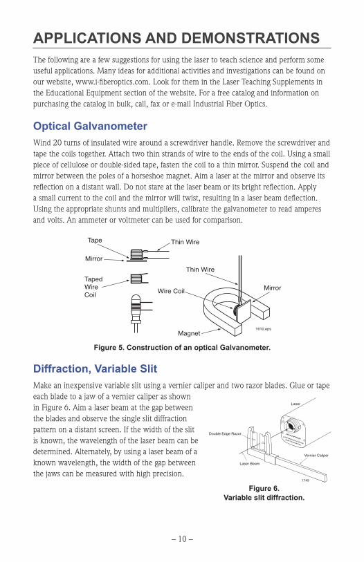
Optical GalvanometerWind 20 turns of insulated wire around a screwdriver handle. Remove the screwdriver and tape the coils together. Attach two thin strands of wire to the ends of the coil. Using a small piece of cellulose or double-sided tape, fasten the coil to a thin mirror. Suspend the coil and mirror between the poles of a horseshoe magnet. Aim a laser at the mirror and observe its reflection on a distant wall. Do not stare at the laser beam or its bright reflection. Apply a small current to the coil and the mirror will twist, resulting in a laser beam deflection. Using the appropriate shunts and multipliers, calibrate the galvanometer to read amperes and volts. An ammeter or voltmeter can be used for comparison.
Diffraction, Variable SlitMake an inexpensive variable slit using a vernier caliper and two razor blades. Glue or tape each blade to a jaw of a vernier caliper as shown in Figure 6. Aim a laser beam at the gap between the blades and observe the single slit diffraction pattern on a distant screen. If the width of the slit is known, the wavelength of the laser beam can be determined. Alternately, by using a laser beam of a known wavelength, the width of the gap between the jaws can be measured with high precision.
Figure 6.Variable slit diffraction.
Mirror
MirrorThin Wire
Thin Wire
Wire Coil
Magnet
Tape
TapedWireCoil
1610.eps
Open
AVOID EXPOSURE
LASER RADIATION IS EMITTED
FROM THIS APERTURE.
Laser
Double Edge Razor
Vernier Caliper
Laser Beam
1749
Figure 5. Construction of an optical Galvanometer.

– 11 –
Laser Light ShowTape a small, lightweight mirror to a speaker cone connected to the output of a radio or tape deck. Shine a laser beam at the mirror, reflecting it onto a wall. The beam will dance around on the wall in a pattern set by the music.
Industrial Fiber Optics’ Laser Optics Lab (45-600) includes lightweight, front-surface mirrors.
Index of Refraction, LiquidsHold a circular protractor in a vertical position and submerge half of it in a large beaker of liquid. Aim the laser so the beam just grazes the front surface of the protractor and passes through its center. Measure the angles of incidence and refraction. Calculate the index of refraction of the liquid using the relationship ή = sin i / sin r. Repeat for different angles of incidence and for different liquids. Water, alcohol and glycerin are suitable for this exercise.
Interference, Evaporation of AlcoholPlace a lens within a laser beam and project the enlarged image onto a viewing screen. Place a drop of alcohol on the lens and allow the alcohol to evaporate. As the evaporation proceeds, changing interference patterns will be observed on the screen.
Figure 8.Refraction of a laser beam.
On
Screen
Laser
Speaker
Mirror
1750
Protractor
Liquids
Beaker
Laser Light
1751
Figure 7. Laser light show.
– 12 –
WARRANTYIndustrial Fiber Optics Hard-Seal Helium-Neon lasers are warranted against defects in materials and workmanship for two years. The warranty will be voided if the laser components have been damaged or mishandled by the buyer, including entry to the laser housing and/or removal of screws.
Industrial Fiber Optics’ warranty liability is limited to repair or replacement of any defective unit at the company’s facilities, and does not include attendant or consequential damages. Repair or replacement may be made only after failure analysis at the factory. Authorized warranty repairs are made at no charge, and are guaranteed for the balance of the original warranty.
Industrial Fiber Optics will pay the return freight and insurance charges for warranty repair within the continental United States by United Parcel Service or Parcel Post. Any other delivery means must be paid for by the customer.
The costs of return shipments for lasers no longer under warranty must be paid by the customer. If an item is not under warranty, repairs will not be undertaken until the cost of such repairs has been approved, in writing, by the customer. Typical repair costs range from $75 - $225 and repairs usually take two to three weeks to complete.
When returning items for analysis and possible repair, please do the following:
• In a letter, describe the problem, person to contact, phone number and return address.
• Pack the laser, power adapter, manual and letter carefully in a strong box with adequate packing material, to prevent damage in shipment.
• Ship the package to:
IndustrIal FIber OptIcs1725 West 1st street
tempe, AZ 85281-7622UsA

– 13 –
SHIPMENT DAMAGE CLAIMSIf damage to an Industrial Fiber Optics product should occur during shipping, it is imperative that it be reported immediately, both to the carrier and the distributor or salesperson from whom the item was purchased. DO NOT CONTACT INDUSTRIAL FIBER OPTICS.
Time is of the essence because damage claims submitted more than five days after delivery may not be honored. If shipping damage has occurred during shipment, please do the following:
• Make a note of the carrier company, the name of the carrier employee, the date and the time of the delivery.
• Keep all packing material.
• In writing, describe the nature of damage to the product.
• In cases of severe damage, do not attempt to use the product (including attaching it to a power source).
• Notify the carrier immediately of any damaged product.
• Notify the distributor from whom the purchase was made.

– 14 –
SERVICE AND MAINTENANCEPeriodic operation, maintenance and service of this laser are not required. The warranty will be voided if entry has been made to the laser housing and/or any screws removed.
In the unlikely event this laser malfunctions and you wish to have it repaired, please do the following:
• In writing, describe the problem, person to contact, phone number and return address.
• Carefully pack the laser, power adapter, manual and written description in a strong box with sufficient packing material to prevent damage in shipment.
• Ship the package to:
IndustrIal FIber OptIcs1725 West 1st street
tempe, AZ 85281-7622UsA

– 15 –
Table 1. Common abbreviations used in this manual.
Abbr Long Version Scientific Notation
mW milliwatts 1 x 10⁻³ watts
µW microwatts 1 x 10⁻⁶ watts
nW nanowatts 1 x 10⁻⁹ watts
mm millimeters 1 x 10⁻³ meters
µm micrometers 1 x 10⁻⁶ meters
nm nanometers 1 x 10⁻⁹ meters

NOTES:

NOTES:

12 0098
Rules for Laser Safety• Lasers produce a very intense beam of light. Treat them with respect. Most
educational lasers have an output of less than 3 milliwatts, and will not harm the skin.
• Never look into the laser aperture while the laser is turned on! PERMANENT EYE DAMAGE COULD RESULT.
• Never stare into the oncoming beam. Never use magnifiers (such as binoculars or telescopes) to look at the beam as it travels – or when it strikes a surface.
• Never point a laser at anyone’s eyes or face, no matter how far away they are.
• When using a laser in the classroom or laboratory, always use a beam stop, or project the beam to areas which people won’t enter or pass through.
• Never leave a laser unattended while it is turned on – and always unplug it when it’s not actually being used.
• Remove all shiny objects from the area in which you will be working. This includes rings, watches, metal bands, tools and glass. Reflections from the beam can be nearly as intense as the beam itself.
• Never disassemble or try to adjust the laser’s internal components. Electric shock could result.