
MIPS IV Instruction Set - TitleFrame · MIPS IV Instruction Set. Rev 3.2 MIPS Technologies, Inc....
328
MIPS IV Instruction Set Revision 3.2 September, 1995 Charles Price
Transcript of MIPS IV Instruction Set - TitleFrame · MIPS IV Instruction Set. Rev 3.2 MIPS Technologies, Inc....
MIPS IV Instruction Set
Revision 3.2
September, 1995
Charles Price
MIPS IV Instruction Set. Rev 3.2
MIPS Technologies, Inc. All Right Reserved
RESTRICTED RIGHTS LEGEND
Use, duplication, or disclosure of the technical data contained in this document bythe Government is subject to restrictions as set forth in subdivision (c) (1) (ii) of theRights in Technical Data and Computer Software clause at DFARS 52.227-7013and / or in similar or successor clauses in the FAR, or in the DOD or NASA FARSupplement. Unpublished rights reserved under the Copyright Laws of theUnited States. Contractor / manufacturer is MIPS Technologies, Inc., 2011 N.Shoreline Blvd., Mountain View, CA 94039-7311.
R2000, R3000, R6000, R4000, R4400, R4200, R8000, R4300 and R10000 aretrademarks of MIPS Technologies, Inc. MIPS and R3000 are registered trademarksof MIPS Technologies, Inc.
The information in this document is preliminary and subject to change withoutnotice. MIPS Technologies, Inc. (MTI) reserves the right to change any portion ofthe product described herein to improve function or design. MTI does not assumeliability arising out of the application or use of any product or circuit describedherein.
Information on MIPS products is available electronically:
(a) Through the World Wide Web. Point your WWW client to:
http://www.mips.com
(b) Through ftp from the internet site “sgigate.sgi.com”. Login as “ftp” or“anonymous” and then cd to the directory “pub/doc”.
(c) Through an automated FAX service:
Inside the USA toll free: (800) 446-6477 (800-IGO-MIPS)
Outside the USA: (415) 688-4321 (call from a FAX machine)
MIPS Technologies, Inc.
2011 N. Shoreline Blvd.
Mountain View, CA 94039-7311
Phone: USA toll free: (800) 998-6477 Outside USA: (415) 933-6477
CPU Instruction Set MIPS IV Instruction Set. Rev 3.2
MIPS IV Instruction Set
CPU Instruction SetIntroduction . . . . . . . . . . . . . . . . . . . . . . . . . . . . . . . . . . . . . . . . . . . . . . . . . . . . . . . . . . . . A-1
Functional Instruction Groups . . . . . . . . . . . . . . . . . . . . . . . . . . . . . . . . . . . . . . . . . . . A-2Load and Store Instructions . . . . . . . . . . . . . . . . . . . . . . A-2
Delayed Loads . . . . . . . . . . . . . . . . . . . . . . . . . . A-3CPU Loads and Stores . . . . . . . . . . . . . . . . . . . . . . . A-4Atomic Update Loads and Stores . . . . . . . . . . . . . . . . . . A-5Coprocessor Loads and Stores . . . . . . . . . . . . . . . . . . . A-5
Computational Instructions . . . . . . . . . . . . . . . . . . . . . . A-6ALU. . . . . . . . . . . . . . . . . . . . . . . . . . . . . . . A-6Shifts . . . . . . . . . . . . . . . . . . . . . . . . . . . . . . A-7Multiply and Divide. . . . . . . . . . . . . . . . . . . . . . . . A-8
Jump and Branch Instructions . . . . . . . . . . . . . . . . . . . . . A-8Miscellaneous Instructions . . . . . . . . . . . . . . . . . . . . . . . A-9
Exception Instructions . . . . . . . . . . . . . . . . . . . . . . . A-9Serialization Instructions . . . . . . . . . . . . . . . . . . . . . A-10Conditional Move Instructions . . . . . . . . . . . . . . . . . . A-10Prefetch . . . . . . . . . . . . . . . . . . . . . . . . . . . . A-10
Coprocessor Instructions . . . . . . . . . . . . . . . . . . . . . . A-11Coprocessor Load and Store . . . . . . . . . . . . . . . . . . . A-12Coprocessor Operations . . . . . . . . . . . . . . . . . . . . . A-12
Memory Access Types. . . . . . . . . . . . . . . . . . . . . . . . . . . . . . . . . . . . . . . . . . . . . . . . . A-12Uncached . . . . . . . . . . . . . . . . . . . . . . . . . . . A-12Cached Noncoherent . . . . . . . . . . . . . . . . . . . . . . A-12Cached Coherent . . . . . . . . . . . . . . . . . . . . . . . . A-13Cached . . . . . . . . . . . . . . . . . . . . . . . . . . . . A-13
Mixing References with Different Access Types. . . . . . . . . . . . . A-13Cache Coherence Algorithms and Access Types . . . . . . . . . . . . A-14Implementation-Specific Access Types . . . . . . . . . . . . . . . . A-14
Description of an Instruction . . . . . . . . . . . . . . . . . . . . . . . . . . . . . . . . . . . . . . . . . . . A-15Instruction mnemonic and name . . . . . . . . . . . . . . . . . . . A-15Instruction encoding picture . . . . . . . . . . . . . . . . . . . . . A-16Format . . . . . . . . . . . . . . . . . . . . . . . . . . . . . . A-16Purpose . . . . . . . . . . . . . . . . . . . . . . . . . . . . . . A-16Description . . . . . . . . . . . . . . . . . . . . . . . . . . . . A-16Restrictions . . . . . . . . . . . . . . . . . . . . . . . . . . . . A-17Operation . . . . . . . . . . . . . . . . . . . . . . . . . . . . . A-17Exceptions . . . . . . . . . . . . . . . . . . . . . . . . . . . . . A-17Programming Notes, Implementation Notes . . . . . . . . . . . . . . A-18
Operation Section Notation and Functions. . . . . . . . . . . . . . . . . . . . . . . . . . . . . . A-18Pseudocode Language . . . . . . . . . . . . . . . . . . . . . . . A-18Pseudocode Symbols . . . . . . . . . . . . . . . . . . . . . . . . A-18Pseudocode Functions. . . . . . . . . . . . . . . . . . . . . . . . A-20
Coprocessor General Register Access Functions . . . . . . . . . . . A-20Load and Store Memory Functions . . . . . . . . . . . . . . . . A-21
MIPS IV Instruction Set. Rev 3.2 CPU Instruction Set
Access Functions for Floating-Point Registers . . . . . . . . . . . . A-24Miscellaneous Functions . . . . . . . . . . . . . . . . . . . . . A-26
Individual CPU Instruction Descriptions . . . . . . . . . . . . . . . . . . . . . . . . . . . . . . . . A-27
CPU Instruction Formats. . . . . . . . . . . . . . . . . . . . . . . . . . . . . . . . . . . . . . . . . . . . . . A-174
CPU Instruction Encoding. . . . . . . . . . . . . . . . . . . . . . . . . . . . . . . . . . . . . . . . . . . . . A-175Instruction Decode . . . . . . . . . . . . . . . . . . . . . . . . . A-175
SPECIAL Instruction Class. . . . . . . . . . . . . . . . . . . . A-175 REGIMM Instruction Class . . . . . . . . . . . . . . . . . . . A-175
Instruction Subsets of MIPS III and MIPS IV Processors. . . . . . . . . . A-175Non-CPU Instructions in the Tables . . . . . . . . . . . . . . . . . . A-176
Coprocessor 0 - COP0 . . . . . . . . . . . . . . . . . . . . . . A-176Coprocessor 1 - COP1, COP1X, MOVCI, and CP1 load/store. . . . . . A-176Coprocessor 2 - COP2 and CP2 load/store. . . . . . . . . . . . . . A-176Coprocessor 3 - COP3 and CP3 load/store. . . . . . . . . . . . . . A-176
FPU Instruction SetIntroduction . . . . . . . . . . . . . . . . . . . . . . . . . . . . . . . . . . . . . . . . . . . . . . . . . . . . . . . . . . . . B-1
FPU Data Types . . . . . . . . . . . . . . . . . . . . . . . . . . . . . . . . . . . . . . . . . . . . . . . . . . . . . . . . B-2Floating-point formats. . . . . . . . . . . . . . . . . . . . . . . . . B-3
Normalized and Denormalized Numbers . . . . . . . . . . . . . . B-4Reserved Operand Values — Infinity and NaN . . . . . . . . . . . . B-4
Fixed-point formats . . . . . . . . . . . . . . . . . . . . . . . . . B-6
Floating-Point Registers. . . . . . . . . . . . . . . . . . . . . . . . . . . . . . . . . . . . . . . . . . . . . . . . . B-6Organization . . . . . . . . . . . . . . . . . . . . . . . . . . . . . B-7Binary Data Transfers . . . . . . . . . . . . . . . . . . . . . . . . . B-7Formatted Operand Layout . . . . . . . . . . . . . . . . . . . . . . B-9Implementation and Revision Register . . . . . . . . . . . . . . . . B-10FPU Control and Status Register — FCSR . . . . . . . . . . . . . . . B-10
Values in FP Registers . . . . . . . . . . . . . . . . . . . . . . . . . . . . . . . . . . . . . . . . . . . . . . . . . B-13
FPU Exceptions . . . . . . . . . . . . . . . . . . . . . . . . . . . . . . . . . . . . . . . . . . . . . . . . . . . . . . . B-14Precise Exception Mode . . . . . . . . . . . . . . . . . . . . . . . B-15Imprecise Exception Mode . . . . . . . . . . . . . . . . . . . . . . B-16Exception Condition Definitions . . . . . . . . . . . . . . . . . . . B-16
Invalid Operation exception . . . . . . . . . . . . . . . . . . . B-17Division By Zero exception . . . . . . . . . . . . . . . . . . . . B-18Overflow exception . . . . . . . . . . . . . . . . . . . . . . . B-18Underflow exception . . . . . . . . . . . . . . . . . . . . . . B-18Inexact exception . . . . . . . . . . . . . . . . . . . . . . . . B-19Unimplemented Operation exception . . . . . . . . . . . . . . . B-19
Functional Instruction Groups . . . . . . . . . . . . . . . . . . . . . . . . . . . . . . . . . . . . . . . . . . B-19Data Transfer Instructions . . . . . . . . . . . . . . . . . . . . . . B-19Arithmetic Instructions . . . . . . . . . . . . . . . . . . . . . . . B-21Conversion Instructions . . . . . . . . . . . . . . . . . . . . . . . B-22Formatted Operand Value Move Instructions. . . . . . . . . . . . . . B-23Conditional Branch Instructions . . . . . . . . . . . . . . . . . . . B-23
CPU Instruction Set MIPS IV Instruction Set. Rev 3.2
Miscellaneous Instructions . . . . . . . . . . . . . . . . . . . . . B-24CPU Conditional Move . . . . . . . . . . . . . . . . . . . . . B-24
Valid Operands for FP Instructions . . . . . . . . . . . . . . . . . . . . . . . . . . . . . . . . . . . . . B-24
Description of an Instruction . . . . . . . . . . . . . . . . . . . . . . . . . . . . . . . . . . . . . . . . . . . B-26
Operation Notation Conventions and Functions. . . . . . . . . . . . . . . . . . . . . . . . . . B-26
Individual FPU Instruction Descriptions . . . . . . . . . . . . . . . . . . . . . . . . . . . . . . . . B-27
FPU Instruction Formats . . . . . . . . . . . . . . . . . . . . . . . . . . . . . . . . . . . . . . . . . . . . . . . B-95
FPU (CP1) Instruction Opcode Bit Encoding. . . . . . . . . . . . . . . . . . . . . . . . . . . . B-98Instruction Decode . . . . . . . . . . . . . . . . . . . . . . . . . B-98
COP1 Instruction Class . . . . . . . . . . . . . . . . . . . . . B-98COP1X Instruction Class . . . . . . . . . . . . . . . . . . . . . B-99SPECIAL Instruction Class . . . . . . . . . . . . . . . . . . . . B-99
Instruction Subsets of MIPS III and MIPS IV Processors. . . . . . . . . . B-99
MIPS IV Instruction Set. Rev 3.2 CPU Instruction Set
List of Figures
Figure A-1. Example Instruction Description . . . . . . . . . . . . . . . . . . . . A-15Figure A-2. Unaligned Doubleword Load using LDL and LDR. . . . . . . . . . . . A-83Figure A-3. Unaligned Doubleword Load using LDR and LDL. . . . . . . . . . . . A-85Figure A-4. Unaligned Word Load using LWL and LWR. . . . . . . . . . . . . . . A-97Figure A-5. Unaligned Word Load using LWR and LWL. . . . . . . . . . . . . . . A-100Figure A-6. Unaligned Doubleword Store with SDL and SDR . . . . . . . . . . . . A-129Figure A-7. Unaligned Doubleword Store with SDR and SDL . . . . . . . . . . . . A-131Figure A-8. Unaligned Word Store using SWL and SWR. . . . . . . . . . . . . . . A-149Figure A-9. Unaligned Word Store using SWR and SWL. . . . . . . . . . . . . . . A-152Figure A-10. CPU Instruction Formats . . . . . . . . . . . . . . . . . . . . . . . A-174Figure B-1. Single-Precision Floating-Point Format (S) . . . . . . . . . . . . . . . . B-3Figure B-2. Double-Precision Floating-Point Format (D) . . . . . . . . . . . . . . . . B-4Figure B-3. Word Fixed-Point Format (W) . . . . . . . . . . . . . . . . . . . . . . B-6Figure B-4. Longword Fixed-Point Format (L) . . . . . . . . . . . . . . . . . . . . B-6Figure B-5. Coprocessor 1 General Registers (FGRs) . . . . . . . . . . . . . . . . . B-7Figure B-6. Effect of FPU Word Load or Move-to Operations . . . . . . . . . . . . . B-8Figure B-7. Effect of FPU Doubleword Load or Move-to Operations . . . . . . . . . . B-8Figure B-8. Floating-point Operand Register (FPR) Organization . . . . . . . . . . . . B-9Figure B-9. Single Floating Point (S) or Word Fixed (W) Operand in an FPR . . . . . . . B-9Figure B-10. Double Floating Point (D) or Long Fixed (L) Operand In an FPR . . . . . . B-10Figure B-11. FPU Implementation and Revision Register . . . . . . . . . . . . . . . B-10Figure B-12. MIPS I - FPU Control and Status Register (FCSR) . . . . . . . . . . . . B-11Figure B-13. MIPS III - FPU Control and Status Register (FCSR) . . . . . . . . . . . . B-11Figure B-14. MIPS IV - FPU Control and Status Register (FCSR) . . . . . . . . . . . . B-11Figure B-15. The Effect of FPU Operations on the Format of Values Held in FPRs. . . . . B-14Figure B-16. FPU Instruction Formats . . . . . . . . . . . . . . . . . . . . . . . B-95
CPU Instruction Set MIPS IV Instruction Set. Rev 3.2
List of Tables
Table A-1. Load/Store Operations Using Register + Offset Addressing Mode. . . . . . A-3Table A-2. Load/Store Operations Using Register + Register Addressing Mode. . . . . A-3Table A-3. Normal CPU Load/Store Instructions . . . . . . . . . . . . . . . . . A-4Table A-4. Unaligned CPU Load/Store Instructions . . . . . . . . . . . . . . . . A-4Table A-5. Atomic Update CPU Load/Store Instructions . . . . . . . . . . . . . . A-5Table A-6. Coprocessor Load/Store Instructions . . . . . . . . . . . . . . . . . A-5Table A-7. FPU Load/Store Instructions Using Register + Register Addressing . . . . A-5Table A-8. ALU Instructions With an Immediate Operand . . . . . . . . . . . . . A-6Table A-9. 3-Operand ALU Instructions . . . . . . . . . . . . . . . . . . . . . A-7Table A-10. Shift Instructions . . . . . . . . . . . . . . . . . . . . . . . . . . A-7Table A-11. Multiply/Divide Instructions . . . . . . . . . . . . . . . . . . . . . A-8Table A-12. Jump Instructions Jumping Within a 256 Megabyte Region . . . . . . . . A-9Table A-13. Jump Instructions to Absolute Address . . . . . . . . . . . . . . . . A-9Table A-14. PC-Relative Conditional Branch Instructions Comparing 2 Registers . . . . A-9Table A-15. PC-Relative Conditional Branch Instructions Comparing Against Zero . . . A-9Table A-16. System Call and Breakpoint Instructions . . . . . . . . . . . . . . . . A-9Table A-17. Trap-on-Condition Instructions Comparing Two Registers . . . . . . . . A-10Table A-18. Trap-on-Condition Instructions Comparing an Immediate . . . . . . . . A-10Table A-19. Serialization Instructions . . . . . . . . . . . . . . . . . . . . . . . A-10Table A-20. CPU Conditional Move Instructions . . . . . . . . . . . . . . . . . . A-10Table A-21. Prefetch Using Register + Offset Address Mode . . . . . . . . . . . . . A-11Table A-22. Prefetch Using Register + Register Address Mode . . . . . . . . . . . . A-11Table A-23. Coprocessor Definition and Use in the MIPS Architecture . . . . . . . . . A-11Table A-24. Coprocessor Operation Instructions . . . . . . . . . . . . . . . . . . A-12Table A-25. Symbols in Instruction Operation Statements . . . . . . . . . . . . . . A-19Table A-26. Coprocessor General Register Access Functions . . . . . . . . . . . . . A-21Table A-27. AccessLength Specifications for Loads/Stores . . . . . . . . . . . . . . A-24Table A-28. Bytes Loaded by LDL Instruction . . . . . . . . . . . . . . . . . . . A-84Table A-29. Bytes Loaded by LDR Instruction . . . . . . . . . . . . . . . . . . . A-86Table A-30. Bytes Loaded by LWL Instruction . . . . . . . . . . . . . . . . . . . A-98Table A-31. Bytes Loaded by LWR Instruction . . . . . . . . . . . . . . . . . . A-101Table A-32. Values of Hint Field for Prefetch Instruction . . . . . . . . . . . . . . A-117Table A-33. Bytes Stored by SDL Instruction . . . . . . . . . . . . . . . . . . . A-130Table A-34. Bytes Stored by SDR Instruction . . . . . . . . . . . . . . . . . . . A-132Table A-35. Bytes Stored by SWL Instruction . . . . . . . . . . . . . . . . . . . A-150Table A-36. Bytes Stored by SWR Instruction . . . . . . . . . . . . . . . . . . . A-153Table A-37. CPU Instruction Encoding - MIPS I Architecture . . . . . . . . . . . . A-177Table A-38. CPU Instruction Encoding - MIPS II Architecture . . . . . . . . . . . A-178Table A-39. CPU Instruction Encoding - MIPS III Architecture . . . . . . . . . . . A-179
MIPS IV Instruction Set. Rev 3.2 CPU Instruction Set
Table A-40. CPU Instruction Encoding - MIPS IV Architecture . . . . . . . . . . . . A-180Table A-41. Architecture Level in Which CPU Instructions are Defined or Extended. . . A-181Table A-42. CPU Instruction Encoding Changes - MIPS II Revision. . . . . . . . . . A-182Table A-43. CPU Instruction Encoding Changes - MIPS III Revision. . . . . . . . . . A-183Table A-44. CPU Instruction Encoding Changes - MIPS IV Revision. . . . . . . . . . A-184Table B-1. Parameters of Floating-Point Formats . . . . . . . . . . . . . . . . . . B-3Table B-2. Value of Single or Double Floating-Point Format Encoding . . . . . . . . . B-4Table B-3. Value Supplied when a new Quiet NaN is Created . . . . . . . . . . . . . B-6Table B-4. Default Result for IEEE Exceptions Not Trapped Precisely . . . . . . . . B-17Table B-5. FPU Loads and Stores Using Register + Offset Address Mode . . . . . . B-20Table B-6. FPU Loads and Using Register + Register Address Mode . . . . . . . . B-20Table B-7. FPU Move To/From Instructions . . . . . . . . . . . . . . . . . . . B-20Table B-8. FPU IEEE Arithmetic Operations . . . . . . . . . . . . . . . . . . . B-21Table B-9. FPU Approximate Arithmetic Operations . . . . . . . . . . . . . . . B-21Table B-10. FPU Multiply-Accumulate Arithmetic Operations . . . . . . . . . . . . B-21Table B-11. FPU Conversion Operations Using the FCSR Rounding Mode . . . . . . B-22Table B-12. FPU Conversion Operations Using a Directed Rounding Mode . . . . . . B-22Table B-13. FPU Formatted Operand Move Instructions . . . . . . . . . . . . . . . B-23Table B-14. FPU Conditional Move on True/False Instructions . . . . . . . . . . . B-23Table B-15. FPU Conditional Move on Zero/Nonzero Instructions . . . . . . . . . B-23Table B-16. FPU Conditional Branch Instructions . . . . . . . . . . . . . . . . . B-24Table B-17. CPU Conditional Move on FPU True/False Instructions . . . . . . . . . B-24Table B-18. FPU Operand Format Field (fmt, fmt3) Decoding . . . . . . . . . . . . B-25Table B-19. Valid Formats for FPU Operations . . . . . . . . . . . . . . . . . . B-25Table B-20. FPU Comparisons Without Special Operand Exceptions . . . . . . . . . B-39Table B-21. FPU Comparisons With Special Operand Exceptions for QNaNs . . . . . B-40Table B-22. Values of Hint Field for Prefetch Instruction . . . . . . . . . . . . . . B-79Table B-23. FPU (CP1) Instruction Encoding - MIPS I Architecture . . . . . . . . . . B-100Table B-24. FPU (CP1) Instruction Encoding - MIPS II Architecture . . . . . . . . . B-102Table B-25. FPU (CP1) Instruction Encoding - MIPS III Architecture . . . . . . . . . B-104Table B-26. FPU (CP1) Instruction Encoding - MIPS IV Architecture . . . . . . . . . B-106Table B-27. Architecture Level In Which FPU Instructions are Defined or Extended. . . B-109Table B-28. FPU Instruction Encoding Changes - MIPS II Architecture Revision. . . . . B-112Table B-29. FPU Instruction Encoding Changes - MIPS III Revision. . . . . . . . . . B-114Table B-30. FPU Instruction Encoding Changes - MIPS IV Revision. . . . . . . . . B-116
CPU Instruction Set MIPS IV Instruction Set. Rev 3.2
Revision History
2.0 (Jan 94): First General Release
This version contained incorrect definitions for MSUB and NMSUB. It did notcontain the RECIP and RSQRT instructions. It contained incomplete or erroneousinformation for LL, LLD, SC, SCD, SYNC, PREF, and PREFX.
All copies of this version of the document should be destroyed
2.2 (Jul 94): Mandatory Replacement of Rev 2.0
This version should probably have been 3.0 since it is a major content change.
This version is issued with no known errors. It includes the late changes to theMIPS IV definition including the reintroduction of RECIP and RSQRT and thedefinition of the multiply-accumulate instructions as unfused (rounded)operations.
3.0 (Oct 94):
Add itemized instruction lists in the discussion of instruction functional groups.
Add a more complete description of FPU operation
Correct problems discovered with Revision 2.2.
3.1 (Jan 95):
Correct minor problems discovered with Revision 3.0.
3.2 (Sep 95):
Revise the opcode encoding tables significantly.
Correct minor problems discovered with Revision 3.1.
Changes from previous revision:
Changes are generally marked by change bars in the outer margin of the page --just like the bar to the side of this line. Minor corrections to punctuation andspelling are neither marked with change bars nor noted in this list. Some changesin figures are not marked by change bars due to limitations of the publishing tools.
CVT.D.fmt Instruction
Change the architecture level for the CVT.D.L version of the instructionfrom:to: MIPS III
MIPS IV Instruction Set. Rev 3.2 CPU Instruction Set
CVT.S.fmt Instruction
Change the architecture level for the CVT.S.L version of the instructionfrom:to: MIPS III
LWL Instruction
In the example in Fig. A-4 the sign extension “After executing LWL $24,2($0)”should be changedfrom: no cng or sign extto: sign bit (31) extend.
The information in the tables later in the instruction description is correct.
MOVF Instruction
Change the name of the constant value in the function fieldfrom: MOVCto: MOVCI
There is a corresponding change in the FPU opcode encoding table in section B.12with opcode=SPECIAL and function=MOVC, changing the value to MOVCI.
MOVF.fmt Instruction
Change the name of the constant value in the function fieldfrom: MOVCto: MOVCF
There is a corresponding change in the FPU opcode encoding table in section B.12with opcode=COP1, fmt = S or D, and function=MOVC, changing the value toMOVCI.
MOVF Instruction
Change the name of the constant value in the function fieldfrom: MOVCto: MOVCI
There is a corresponding change in the FPU opcode encoding table in section B.12with opcode=SPECIAL and function=MOVC, changing the value to MOVCI.
MOVT.fmt Instruction
Change the name of the constant value in the function fieldfrom: MOVCto: MOVCF
There is a corresponding change in the FPU opcode encoding table in section B.12with opcode=COP1, fmt = S or D, and function=MOVC, changing the value toMOVCI.
CPU Instruction Set MIPS IV Instruction Set. Rev 3.2
CPU Instruction Encoding tables
Revise the presentation of the opcode encoding in section A 8 for greater claritywhen considering different architecture levels or operating a MIPS III or MIPS IVprocessor in the MIPS II or MIPS III instruction subset modes.
There is a separate encoding table for each architecture level. There is a table of theMIPS IV encodings showing the architecture level at which each opcode was firstdefined and subsequently modified or extended. There is a separate table for eacharchitecture revision Ι→II, II→III, and III→IV showing the changes made in thatrevision.
FPU Instruction Encoding tables
Revise the presentation of the opcode encoding in section B.12 for greater claritywhen considering different architecture levels or operating a MIPS III or MIPS IVprocessor in the MIPS II or MIPS III instruction subset modes.
There is a separate encoding table for each architecture level. There is a table of theMIPS IV encodings showing the architecture level at which each opcode was firstdefined and subsequently modified or extended. There is a separate table for eacharchitecture revision Ι→II, II→III, and III→IV showing the changes made in thatrevision.

MIPS IV Instruction Set. Rev 3.2 CPU Instruction Set
CPU Instruction Set MIPS IV Instruction Set. Rev 3.2 A-1
CPU Instruction Set
A
A 1 Introduction
This appendix describes the instruction set architecture (ISA) for the centralprocessing unit (CPU) in the MIPS IV architecture. The CPU architecture definesthe non-privileged instructions that execute in user mode. It does not defineprivileged instructions providing processor control executed by theimplementation-specific System Control Processor. Instructions for the floating-point unit are described in Appendix B.
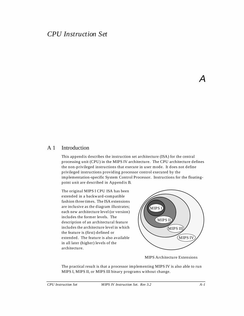
The practical result is that a processor implementing MIPS IV is also able to runMIPS I, MIPS II, or MIPS III binary programs without change.
MIPS I
MIPS II
MIPS III
MIPS IV
The original MIPS I CPU ISA has beenextended in a backward-compatiblefashion three times. The ISA extensionsare inclusive as the diagram illustrates;each new architecture level (or version)includes the former levels. Thedescription of an architectural featureincludes the architecture level in whichthe feature is (first) defined orextended. The feature is also availablein all later (higher) levels of thearchitecture.
MIPS Architecture Extensions
A-2 MIPS IV Instruction Set. Rev 3.2 CPU Instruction Set
The CPU instruction set is first summarized by functional group then eachinstruction is described separately in alphabetical order. The appendix describesthe organization of the individual instruction descriptions and the notation usedin them (including FPU instructions). It concludes with the CPU instructionformats and opcode encoding tables.
A 2 Functional Instruction Groups
CPU instructions are divided into the following functional groups:
• Load and Store
• ALU
• Jump and Branch
• Miscellaneous
• Coprocessor
A 2.1 Load and Store Instructions
Load and store instructions transfer data between the memory system and thegeneral register sets in the CPU and the coprocessors. There are separateinstructions for different purposes: transferring various sized fields, treatingloaded data as signed or unsigned integers, accessing unaligned fields, selectingthe addressing mode, and providing atomic memory update (read-modify-write).
Regardless of byte ordering (big- or little-endian), the address of a halfword, word,or doubleword is the smallest byte address among the bytes forming the object.For big-endian ordering this is the most-significant byte; for a little-endianordering this is the least-significant byte.
Except for the few specialized instructions listed in Table A-4, loads and storesmust access naturally aligned objects. An attempt to load or store an object at anaddress that is not an even multiple of the size of the object will cause an AddressError exception.
Load and store operations have been added in each revision of the architecture:
MIPS II
• 64-bit coprocessor transfers
• atomic update
MIPS III
• 64-bit CPU transfers
• unsigned word load for CPU
MIPS IV
• register + register addressing mode for FPU
CPU Instruction Set MIPS IV Instruction Set. Rev 3.2 A-3
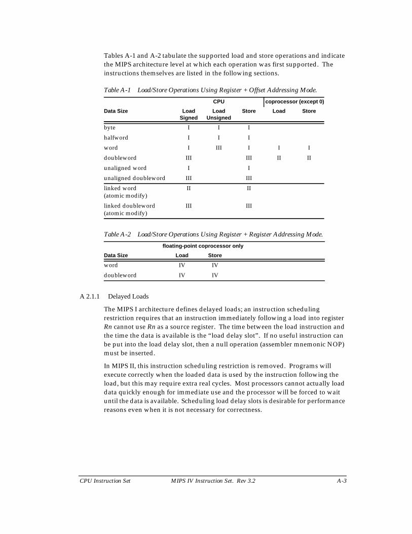
Tables A-1 and A-2 tabulate the supported load and store operations and indicatethe MIPS architecture level at which each operation was first supported. Theinstructions themselves are listed in the following sections.
Table A-1 Load/Store Operations Using Register + Offset Addressing Mode.
Table A-2 Load/Store Operations Using Register + Register Addressing Mode.
A 2.1.1 Delayed Loads
The MIPS I architecture defines delayed loads; an instruction schedulingrestriction requires that an instruction immediately following a load into registerRn cannot use Rn as a source register. The time between the load instruction andthe time the data is available is the “load delay slot”. If no useful instruction canbe put into the load delay slot, then a null operation (assembler mnemonic NOP)must be inserted.
In MIPS II, this instruction scheduling restriction is removed. Programs willexecute correctly when the loaded data is used by the instruction following theload, but this may require extra real cycles. Most processors cannot actually loaddata quickly enough for immediate use and the processor will be forced to waituntil the data is available. Scheduling load delay slots is desirable for performancereasons even when it is not necessary for correctness.
CPU coprocessor (except 0)
Data Size LoadSigned
LoadUnsigned
Store Load Store
byte I I I
halfword I I I
word I III I I I
doubleword III III II II
unaligned word I I
unaligned doubleword III III
linked word(atomic modify)
II II
linked doubleword(atomic modify)
III III
floating-point coprocessor only
Data Size Load Store
word IV IV
doubleword IV IV
A-4 MIPS IV Instruction Set. Rev 3.2 CPU Instruction Set
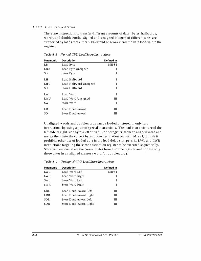
A 2.1.2 CPU Loads and Stores
There are instructions to transfer different amounts of data: bytes, halfwords,words, and doublewords. Signed and unsigned integers of different sizes aresupported by loads that either sign-extend or zero-extend the data loaded into theregister.
Table A-3 Normal CPU Load/Store Instructions
Unaligned words and doublewords can be loaded or stored in only twoinstructions by using a pair of special instructions. The load instructions read theleft-side or right-side bytes (left or right side of register) from an aligned word andmerge them into the correct bytes of the destination register. MIPS I, though itprohibits other use of loaded data in the load delay slot, permits LWL and LWRinstructions targeting the same destination register to be executed sequentially.Store instructions select the correct bytes from a source register and update onlythose bytes in an aligned memory word (or doubleword).
Table A-4 Unaligned CPU Load/Store Instructions
Mnemonic Description Defined in
LB Load Byte MIPS ILBU Load Byte Unsigned ISB Store Byte I
LH Load Halfword ILHU Load Halfword Unsigned ISH Store Halfword I
LW Load Word ILWU Load Word Unsigned IIISW Store Word I
LD Load Doubleword IIISD Store Doubleword III
Mnemonic Description Defined in
LWL Load Word Left MIPS ILWR Load Word Right ISWL Store Word Left ISWR Store Word Right I
LDL Load Doubleword Left IIILDR Load Doubleword Right IIISDL Store Doubleword Left IIISDR Store Doubleword Right III
CPU Instruction Set MIPS IV Instruction Set. Rev 3.2 A-5
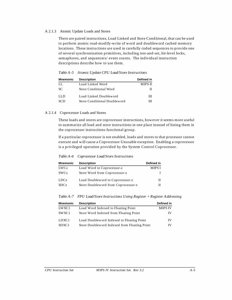
A 2.1.3 Atomic Update Loads and Stores
There are paired instructions, Load Linked and Store Conditional, that can be usedto perform atomic read-modify-write of word and doubleword cached memorylocations. These instructions are used in carefully coded sequences to provide oneof several synchronization primitives, including test-and-set, bit-level locks,semaphores, and sequencers/event counts. The individual instructiondescriptions describe how to use them.
Table A-5 Atomic Update CPU Load/Store Instructions
A 2.1.4 Coprocessor Loads and Stores
These loads and stores are coprocessor instructions, however it seems more usefulto summarize all load and store instructions in one place instead of listing them inthe coprocessor instructions functional group.
If a particular coprocessor is not enabled, loads and stores to that processor cannotexecute and will cause a Coprocessor Unusable exception. Enabling a coprocessoris a privileged operation provided by the System Control Coprocessor.
Table A-6 Coprocessor Load/Store Instructions
Table A-7 FPU Load/Store Instructions Using Register + Register Addressing
Mnemonic Description Defined in
LL Load Linked Word MIPS IISC Store Conditional Word II
LLD Load Linked Doubleword IIISCD Store Conditional Doubleword III
Mnemonic Description Defined in
LWCz Load Word to Coprocessor-z MIPS ISWCz Store Word from Coprocessor-z I
LDCz Load Doubleword to Coprocessor-z IISDCz Store Doubleword from Coprocessor-z II
Mnemonic Description Defined in
LWXC1 Load Word Indexed to Floating Point MIPS IVSWXC1 Store Word Indexed from Floating Point IV
LDXC1 Load Doubleword Indexed to Floating Point IVSDXC1 Store Doubleword Indexed from Floating Point IV
A-6 MIPS IV Instruction Set. Rev 3.2 CPU Instruction Set
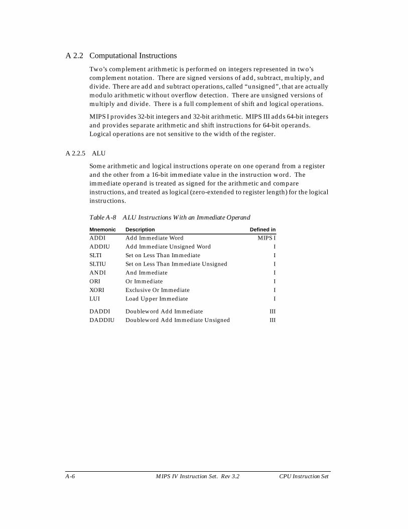
A 2.2 Computational Instructions
Two’s complement arithmetic is performed on integers represented in two’scomplement notation. There are signed versions of add, subtract, multiply, anddivide. There are add and subtract operations, called “unsigned”, that are actuallymodulo arithmetic without overflow detection. There are unsigned versions ofmultiply and divide. There is a full complement of shift and logical operations.
MIPS I provides 32-bit integers and 32-bit arithmetic. MIPS III adds 64-bit integersand provides separate arithmetic and shift instructions for 64-bit operands.Logical operations are not sensitive to the width of the register.
A 2.2.5 ALU
Some arithmetic and logical instructions operate on one operand from a registerand the other from a 16-bit immediate value in the instruction word. Theimmediate operand is treated as signed for the arithmetic and compareinstructions, and treated as logical (zero-extended to register length) for the logicalinstructions.
Table A-8 ALU Instructions With an Immediate Operand
Mnemonic Description Defined in
ADDI Add Immediate Word MIPS IADDIU Add Immediate Unsigned Word ISLTI Set on Less Than Immediate ISLTIU Set on Less Than Immediate Unsigned IANDI And Immediate IORI Or Immediate IXORI Exclusive Or Immediate ILUI Load Upper Immediate I
DADDI Doubleword Add Immediate IIIDADDIU Doubleword Add Immediate Unsigned III
CPU Instruction Set MIPS IV Instruction Set. Rev 3.2 A-7
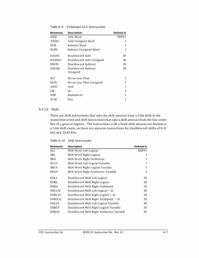
Table A-9 3-Operand ALU Instructions
A 2.2.6 Shifts
There are shift instructions that take the shift amount from a 5-bit field in theinstruction word and shift instructions that take a shift amount from the low-orderbits of a general register. The instructions with a fixed shift amount are limited toa 5-bit shift count, so there are separate instructions for doubleword shifts of 0-31bits and 32-63 bits.
Table A-10 Shift Instructions
Mnemonic Description Defined in
ADD Add Word MIPS IADDU Add Unsigned Word ISUB Subtract Word ISUBU Subtract Unsigned Word I
DADD Doubleword Add IIIDADDU Doubleword Add Unsigned IIIDSUB Doubleword Subtract IIIDSUBU Doubleword Subtract
UnsignedIII
SLT Set on Less Than ISLTU Set on Less Than Unsigned IAND And IOR Or IXOR Exclusive Or INOR Nor I
Mnemonic Description Defined in
SLL Shift Word Left Logical MIPS ISRL Shift Word Right Logical ISRA Shift Word Right Arithmetic ISLLV Shift Word Left Logical Variable ISRLV Shift Word Right Logical Variable ISRAV Shift Word Right Arithmetic Variable I
DSLL Doubleword Shift Left Logical IIIDSRL Doubleword Shift Right Logical IIIDSRA Doubleword Shift Right Arithmetic IIIDSLL32 Doubleword Shift Left Logical + 32 IIIDSRL32 Doubleword Shift Right Logical + 32 IIIDSRA32 Doubleword Shift Right Arithmetic + 32 IIIDSLLV Doubleword Shift Left Logical Variable IIIDSRLV Doubleword Shift Right Logical Variable IIIDSRAV Doubleword Shift Right Arithmetic Variable III
A-8 MIPS IV Instruction Set. Rev 3.2 CPU Instruction Set
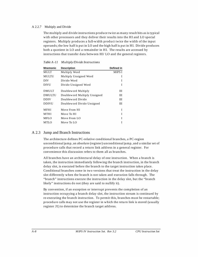
A 2.2.7 Multiply and Divide
The multiply and divide instructions produce twice as many result bits as is typicalwith other processors and they deliver their results into the HI and LO specialregisters. Multiply produces a full-width product twice the width of the inputoperands; the low half is put in LO and the high half is put in HI. Divide producesboth a quotient in LO and a remainder in HI. The results are accessed byinstructions that transfer data between HI/LO and the general registers.
Table A-11 Multiply/Divide Instructions
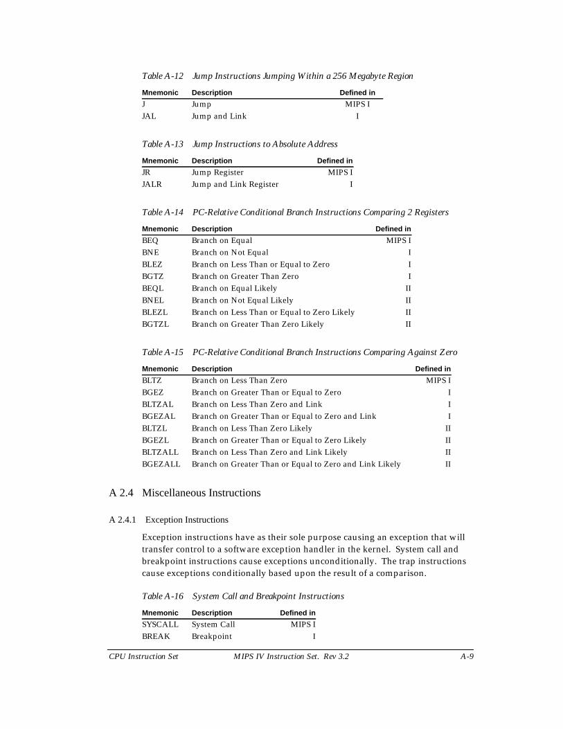
A 2.3 Jump and Branch Instructions
The architecture defines PC-relative conditional branches, a PC-regionunconditional jump, an absolute (register) unconditional jump, and a similar set ofprocedure calls that record a return link address in a general register. Forconvenience this discussion refers to them all as branches.
All branches have an architectural delay of one instruction. When a branch istaken, the instruction immediately following the branch instruction, in the branchdelay slot, is executed before the branch to the target instruction takes place.Conditional branches come in two versions that treat the instruction in the delayslot differently when the branch is not taken and execution falls through. The“branch” instructions execute the instruction in the delay slot, but the “branchlikely” instructions do not (they are said to nullify it).
By convention, if an exception or interrupt prevents the completion of aninstruction occupying a branch delay slot, the instruction stream is continued byre-executing the branch instruction. To permit this, branches must be restartable;procedure calls may not use the register in which the return link is stored (usuallyregister 31) to determine the branch target address.
Mnemonic Description Defined in
MULT Multiply Word MIPS IMULTU Multiply Unsigned Word IDIV Divide Word IDIVU Divide Unsigned Word I
DMULT Doubleword Multiply IIIDMULTU Doubleword Multiply Unsigned IIIDDIV Doubleword Divide IIIDDIVU Doubleword Divide Unsigned III
MFHI Move From HI IMTHI Move To HI IMFLO Move From LO IMTLO Move To LO I
CPU Instruction Set MIPS IV Instruction Set. Rev 3.2 A-9
Table A-12 Jump Instructions Jumping Within a 256 Megabyte Region
Table A-13 Jump Instructions to Absolute Address
Table A-14 PC-Relative Conditional Branch Instructions Comparing 2 Registers
Table A-15 PC-Relative Conditional Branch Instructions Comparing Against Zero
A 2.4 Miscellaneous Instructions
A 2.4.1 Exception Instructions
Exception instructions have as their sole purpose causing an exception that willtransfer control to a software exception handler in the kernel. System call andbreakpoint instructions cause exceptions unconditionally. The trap instructionscause exceptions conditionally based upon the result of a comparison.
Table A-16 System Call and Breakpoint Instructions
Mnemonic Description Defined in
J Jump MIPS IJAL Jump and Link I
Mnemonic Description Defined in
JR Jump Register MIPS IJALR Jump and Link Register I
Mnemonic Description Defined in
BEQ Branch on Equal MIPS IBNE Branch on Not Equal IBLEZ Branch on Less Than or Equal to Zero IBGTZ Branch on Greater Than Zero IBEQL Branch on Equal Likely IIBNEL Branch on Not Equal Likely IIBLEZL Branch on Less Than or Equal to Zero Likely IIBGTZL Branch on Greater Than Zero Likely II
Mnemonic Description Defined in
BLTZ Branch on Less Than Zero MIPS IBGEZ Branch on Greater Than or Equal to Zero IBLTZAL Branch on Less Than Zero and Link IBGEZAL Branch on Greater Than or Equal to Zero and Link IBLTZL Branch on Less Than Zero Likely IIBGEZL Branch on Greater Than or Equal to Zero Likely IIBLTZALL Branch on Less Than Zero and Link Likely IIBGEZALL Branch on Greater Than or Equal to Zero and Link Likely II
Mnemonic Description Defined in
SYSCALL System Call MIPS IBREAK Breakpoint I
A-10 MIPS IV Instruction Set. Rev 3.2 CPU Instruction Set
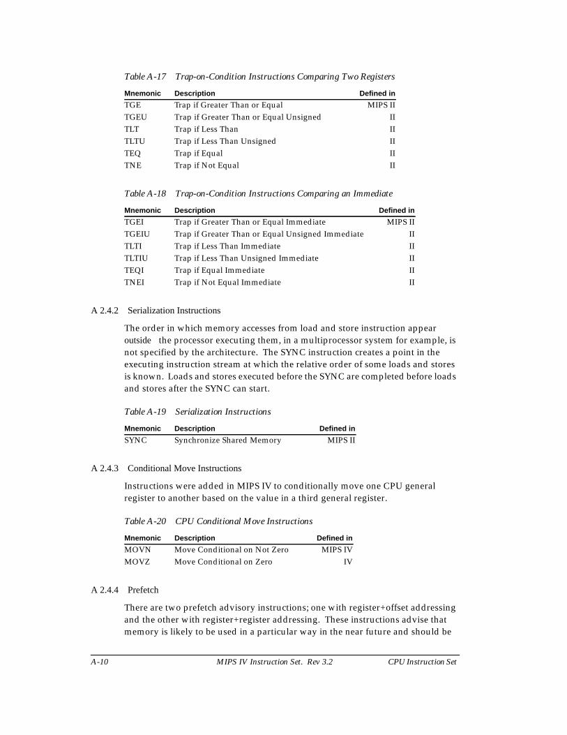
Table A-17 Trap-on-Condition Instructions Comparing Two Registers
Table A-18 Trap-on-Condition Instructions Comparing an Immediate
A 2.4.2 Serialization Instructions
The order in which memory accesses from load and store instruction appearoutside the processor executing them, in a multiprocessor system for example, isnot specified by the architecture. The SYNC instruction creates a point in theexecuting instruction stream at which the relative order of some loads and storesis known. Loads and stores executed before the SYNC are completed before loadsand stores after the SYNC can start.
Table A-19 Serialization Instructions
A 2.4.3 Conditional Move Instructions
Instructions were added in MIPS IV to conditionally move one CPU generalregister to another based on the value in a third general register.
Table A-20 CPU Conditional Move Instructions
A 2.4.4 Prefetch
There are two prefetch advisory instructions; one with register+offset addressingand the other with register+register addressing. These instructions advise thatmemory is likely to be used in a particular way in the near future and should be
Mnemonic Description Defined in
TGE Trap if Greater Than or Equal MIPS IITGEU Trap if Greater Than or Equal Unsigned IITLT Trap if Less Than IITLTU Trap if Less Than Unsigned IITEQ Trap if Equal IITNE Trap if Not Equal II
Mnemonic Description Defined in
TGEI Trap if Greater Than or Equal Immediate MIPS IITGEIU Trap if Greater Than or Equal Unsigned Immediate IITLTI Trap if Less Than Immediate IITLTIU Trap if Less Than Unsigned Immediate IITEQI Trap if Equal Immediate IITNEI Trap if Not Equal Immediate II
Mnemonic Description Defined in
SYNC Synchronize Shared Memory MIPS II
Mnemonic Description Defined in
MOVN Move Conditional on Not Zero MIPS IVMOVZ Move Conditional on Zero IV
CPU Instruction Set MIPS IV Instruction Set. Rev 3.2 A-11
prefetched into the cache. The PREFX instruction using register+registeraddressing mode is coded in the FPU opcode space along with the otheroperations using register+register addressing.
Table A-21 Prefetch Using Register + Offset Address Mode
Table A-22 Prefetch Using Register + Register Address Mode
A 2.5 Coprocessor Instructions
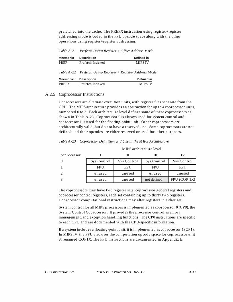
Coprocessors are alternate execution units, with register files separate from theCPU. The MIPS architecture provides an abstraction for up to 4 coprocessor units,numbered 0 to 3. Each architecture level defines some of these coprocessors asshown in Table A-23. Coprocessor 0 is always used for system control andcoprocessor 1 is used for the floating-point unit. Other coprocessors arearchitecturally valid, but do not have a reserved use. Some coprocessors are notdefined and their opcodes are either reserved or used for other purposes.
Table A-23 Coprocessor Definition and Use in the MIPS Architecture
The coprocessors may have two register sets, coprocessor general registers andcoprocessor control registers, each set containing up to thirty two registers.Coprocessor computational instructions may alter registers in either set.
System control for all MIPS processors is implemented as coprocessor 0 (CP0), theSystem Control Coprocessor. It provides the processor control, memorymanagement, and exception handling functions. The CP0 instructions are specificto each CPU and are documented with the CPU-specific information.
If a system includes a floating-point unit, it is implemented as coprocessor 1 (CP1).In MIPS IV, the FPU also uses the computation opcode space for coprocessor unit3, renamed COP1X. The FPU instructions are documented in Appendix B.
Mnemonic Description Defined in
PREF Prefetch Indexed MIPS IV
Mnemonic Description Defined in
PREFX Prefetch Indexed MIPS IV
MIPS architecture level
coprocessor I II III IV
0 Sys Control Sys Control Sys Control Sys Control
1 FPU FPU FPU FPU
2 unused unused unused unused
3 unused unused not defined FPU (COP 1X)
A-12 MIPS IV Instruction Set. Rev 3.2 CPU Instruction Set
The coprocessor instructions are divided into two main groups:
• Load and store instructions that are reserved in the main opcode space.
• Coprocessor-specific operations that are defined entirely by thecoprocessor.
A 2.5.1 Coprocessor Load and Store
Load and store instructions are not defined for CP0; the move to/from coprocessorinstructions are the only way to write and read the CP0 registers.
The loads and stores for coprocessors are summarized in Load and StoreInstructions on page A-2.
A 2.5.2 Coprocessor Operations
There are up to four coprocessors and the instructions are shown generically forcoprocessor-z. Within the operation main opcode, the coprocessor has furthercoprocessor-specific instructions encoded.
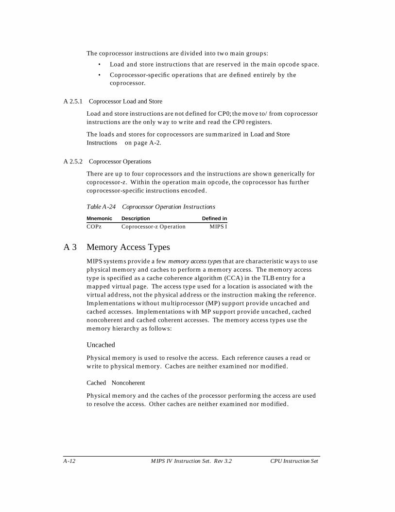
Table A-24 Coprocessor Operation Instructions
A 3 Memory Access Types
MIPS systems provide a few memory access types that are characteristic ways to usephysical memory and caches to perform a memory access. The memory accesstype is specified as a cache coherence algorithm (CCA) in the TLB entry for amapped virtual page. The access type used for a location is associated with thevirtual address, not the physical address or the instruction making the reference.Implementations without multiprocessor (MP) support provide uncached andcached accesses. Implementations with MP support provide uncached, cachednoncoherent and cached coherent accesses. The memory access types use thememory hierarchy as follows:
Uncached
Physical memory is used to resolve the access. Each reference causes a read orwrite to physical memory. Caches are neither examined nor modified.
Cached Noncoherent
Physical memory and the caches of the processor performing the access are usedto resolve the access. Other caches are neither examined nor modified.
Mnemonic Description Defined in
COPz Coprocessor-z Operation MIPS I
CPU Instruction Set MIPS IV Instruction Set. Rev 3.2 A-13
Cached Coherent
Physical memory and all caches in the system containing a coherent copy of thephysical location are used to resolve the access. A copy of a location is coherent(noncoherent) if the copy was placed in the cache by a cached coherent (cachednoncoherent) access. Caches containing a coherent copy of the location areexamined and/or modified to keep the contents of the location coherent. It isunpredictable whether caches holding a noncoherent copy of the location areexamined and/or modified during a cached coherent access.
Cached
For early 32-bit processors without MP support, cached is equivalent to cachednoncoherent. If an instruction description mentions the cached noncoherentaccess type, the comment applies equally to the cached access type in a processorthat has the cached access type.
For processors with MP support, cached is a collective term, e.g. “cached memory”or “cached access”, that includes both cached noncoherent and cached coherent.Such a collective use does not imply that cached is an access type, it means that thestatement applies equally to cached noncoherent and cached coherent accesstypes.
A 3.1 Mixing References with Different Access Types
It is possible to have more than one virtual location simultaneously mapped to thesame physical location. The memory access type used for the virtual mappingsmay be different, but it is not generally possible to use mappings with differentaccess types at the same time.
A processor executing load and store instructions must observe the effect of theload and store instructions to a physical location in the order that they occur in theinstruction stream (i.e. program order) for all accesses to virtual locations with thesame memory access type.
If a processor executes a load or store using one access type to a physical location,the behavior of a subsequent load or store to the same location using a differentmemory access type is undefined unless a privileged instruction sequence isexecuted between the two accesses. Each implementation has a privilegedimplementation-specific mechanism that must be used to change the access typebeing used to access a location.
The memory access type of a location affects the behavior of I-fetch, load, store,and prefetch operations to the location. In addition, memory access types affectsome instruction descriptions. Load linked (LL, LLD) and store conditional (SC,SCD) have defined operation only for locations with cached memory access type.SYNC affects only load and stores made to locations with uncached or cachedcoherent memory access types.
A-14 MIPS IV Instruction Set. Rev 3.2 CPU Instruction Set
A 3.2 Cache Coherence Algorithms and Access Types
The memory access types are specified by implementation-specific cachecoherence algorithms (CCAs) in TLB entries. Slightly different cache coherencealgorithms such as “cached coherent, update on write” and “cached coherent,exclusive on write” can map to the same memory access type, in this case they bothmap to cached coherent. In order to map to the same access type the fundamentalmechanism of both CCAs must be the same. When it affects the operation of theinstruction, the instructions are described in terms of the memory access types.The load and store operations in a processor proceeds according to the specificCCA of the reference, however, and the pseudocode for load and store commonfunctions in the section Load and Store Memory Functions on page A-21 use theCCA value rather than the corresponding memory access type.
A 3.3 Implementation-Specific Access Types
An implementation may provide memory access types other than uncached,cached noncoherent, or cached coherent. Implementation-specific documentationwill define the properties of the new access types and their effect on all memory-related operations.
CPU Instruction Set MIPS IV Instruction Set. Rev 3.2 A-15
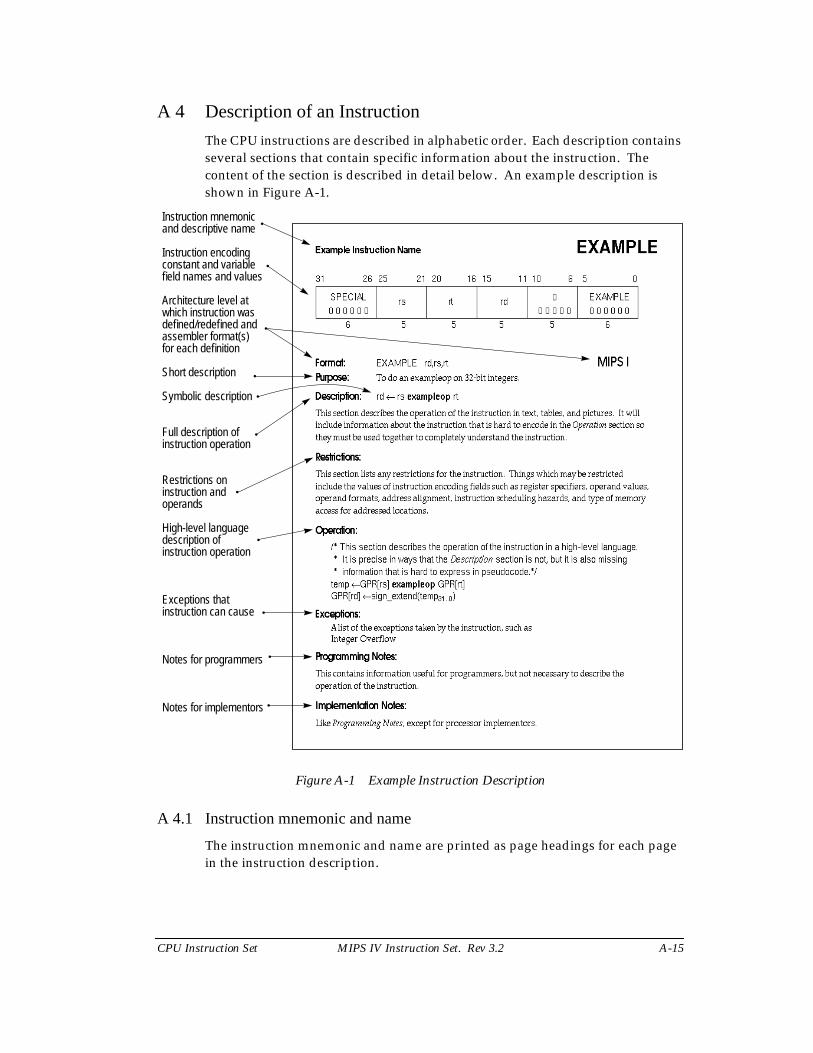
A 4 Description of an Instruction
The CPU instructions are described in alphabetic order. Each description containsseveral sections that contain specific information about the instruction. Thecontent of the section is described in detail below. An example description isshown in Figure A-1.
Figure A-1 Example Instruction Description
A 4.1 Instruction mnemonic and name
The instruction mnemonic and name are printed as page headings for each pagein the instruction description.
Instruction mnemonicand descriptive name
Instruction encodingconstant and variablefield names and values
Architecture level at
Short description
Symbolic description
Full description ofinstruction operation
Restrictions oninstruction and
High-level languagedescription of
Exceptions thatinstruction can cause
Notes for programmers
operands
which instruction wasdefined/redefined andassembler format(s)for each definition
instruction operation
Notes for implementors
•
•
•
•
•
•
•
•
•
•
•
A-16 MIPS IV Instruction Set. Rev 3.2 CPU Instruction Set
A 4.2 Instruction encoding picture
The instruction word encoding is shown in pictorial form at the top of theinstruction description. This picture shows the values of all constant fields and theopcode names for opcode fields in upper-case. It labels all variable fields withlower-case names that are used in the instruction description. Fields that containzeroes but are not named are unused fields that are required to be zero. Asummary of the instruction formats and a definition of the terms used to describethe contents can be found in CPU Instruction Formats on page A-174.
A 4.3 Format
The assembler formats for the instruction and the architecture level at which theinstruction was originally defined are shown. If the instruction definition waslater extended, the architecture levels at which it was extended and the assemblerformats for the extended definition are shown in order of extension. The MIPSarchitecture levels are inclusive; higher architecture levels include all instructionsin previous levels. Extensions to instructions are backwards compatible. Theoriginal assembler formats are valid for the extended architecture.
The assembler format is shown with literal parts of the assembler instruction inupper-case characters. The variable parts, the operands, are shown as the lower-case names of the appropriate fields in the instruction encoding picture. Thearchitecture level at which the instruction was first defined, e.g. “MIPS I”, isshown at the right side of the page.
There can be more than one assembler format per architecture level. This issometimes an alternate form of the instruction. Floating-point operations onformatted data show an assembly format with the actual assembler mnemonic foreach valid value of the “fmt” field. For example the ADD.fmt instruction showsADD.S and ADD.D.
The assembler format lines sometimes have comments to the right in parenthesesto help explain variations in the formats. The comments are not a part of theassembler format.
A 4.4 Purpose
This is a very short statement of the purpose of the instruction.
A 4.5 Description
If a one-line symbolic description of the instruction is feasible, it will appearimmediately to the right of the Description heading. The main purpose is to showhow fields in the instruction are used in the arithmetic or logical operation.
The body of the section is a description of the operation of the instruction in text,tables, and figures. This description complements the high-level languagedescription in the Operation section.
CPU Instruction Set MIPS IV Instruction Set. Rev 3.2 A-17
This section uses acronyms for register descriptions. “GPR rt” is CPU GeneralPurpose Register specified by the instruction field rt. “FPR fs” is the Floating PointOperand Register specified by the instruction field fs. “CP1 register fd” is thecoprocessor 1 General Register specified by the instruction field fd. “FCSR” is thefloating-point control and status register.
A 4.6 Restrictions
This section documents the restrictions on the instruction. Most restrictions fallinto one of six categories:
• The valid values for instruction fields (see floating-point ADD.fmt).
• The alignment requirements for memory addresses (see LW).
• The valid values of operands (see DADD).
• The valid operand formats (see floating-point ADD.fmt).
• The order of instructions necessary to guarantee correct execution. Theseordering constraints avoid pipeline hazards for which some processors donot have hardware interlocks (see MUL).
• The valid memory access types (see LL/SC).
A 4.7 Operation
This section describes the operation of the instruction as pseudocode in a high-level language notation resembling Pascal. The purpose of this section is todescribe the operation of the instruction clearly in a form with less ambiguity thanprose. This formal description complements the Description section; it is notcomplete in itself because many of the restrictions are either difficult to include inthe pseudocode or omitted for readability.
There will be separate Operation sections for 32-bit and 64-bit processors if theoperation is different. This is usually necessary because the path to memory is adifferent size on these processors.
See Operation Section Notation and Functions on page A-18 for moreinformation on the formal notation.
A 4.8 Exceptions
This section lists the exceptions that can be caused by operation of the instruction.It omits exceptions that can be caused by instruction fetch, e.g. TLB Refill. It omitsexceptions that can be caused by asynchronous external events, e.g. Interrupt.Although the Bus Error exception may be caused by the operation of a load or storeinstruction this section does not list Bus Error for load and store instructionsbecause the relationship between load and store instructions and external errorindications, like Bus Error, are implementation dependent.
A-18 MIPS IV Instruction Set. Rev 3.2 CPU Instruction Set
Reserved Instruction is listed for every instruction not in MIPS I because theinstruction will cause this exception on a MIPS I processor. To execute a MIPS II,MIPS III, or MIPS IV instruction, the processor must both support the architecturelevel and have it enabled. The mechanism to do this is implementation specific.
The mechanism used to signal a floating-point unit (FPU) exception isimplementation specific. Some implementations use the exception named“Floating Point”. Others use external interrupts (the Interrupt exception). Thissection lists Floating Point to represent all such mechanisms. The specific FPUtraps possible are listed, indented, under the Floating Point entry.
The usual floating-point exception model for MIPS architecture processors isprecise exceptions. However, the R8000 processor, the first implementation of theMIPS IV architecture, normally operates with imprecise floating-point exceptions.It also has a mode in which it operates with degraded floating-point performancebut provides precise exceptions compatible with other MIPS processors. This ismentioned in the description of some floating-point instructions. A generaldescription of this exception model is not included in this document. See the“MIPS R8000 Microprocessor Chip Set Users Manual” for more information.
An instruction may cause implementation-dependent exceptions that are notpresent in the Exceptions section.
A 4.9 Programming Notes, Implementation Notes
These sections contain material that is useful for programmers and implementorsrespectively but that is not necessary to describe the instruction and does notbelong in the description sections.
A 5 Operation Section Notation and Functions
In an instruction description, the Operation section describes the operationperformed by each instruction using a high-level language notation. The contentsof the Operation section are described here. The special symbols and functionsused are documented here.
A 5.1 Pseudocode Language
Each of the high-level language statements is executed in sequential order (asmodified by conditional and loop constructs).
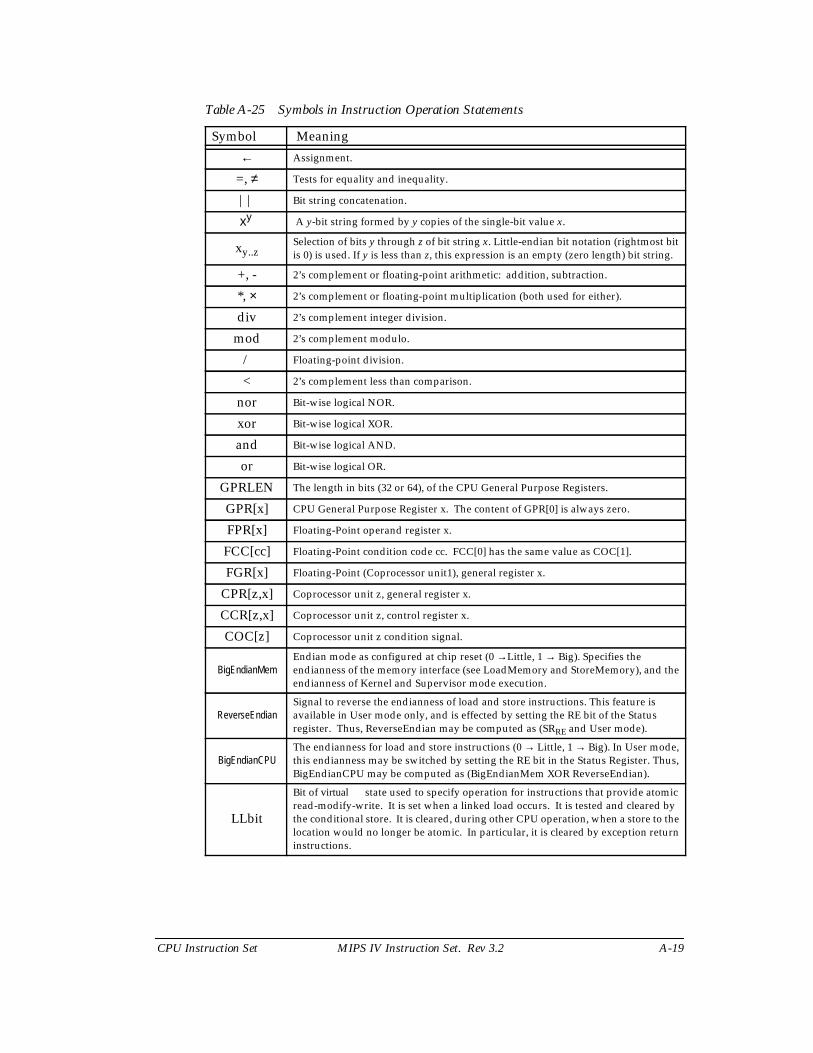
A 5.2 Pseudocode Symbols
Special symbols used in the notation are described in Table A-25.
CPU Instruction Set MIPS IV Instruction Set. Rev 3.2 A-19
Table A-25 Symbols in Instruction Operation Statements
Symbol Meaning
← Assignment.
=, ≠ Tests for equality and inequality.
|| Bit string concatenation.
xy A y-bit string formed by y copies of the single-bit value x.
xy..zSelection of bits y through z of bit string x. Little-endian bit notation (rightmost bitis 0) is used. If y is less than z, this expression is an empty (zero length) bit string.
+, - 2’s complement or floating-point arithmetic: addition, subtraction.
*, × 2’s complement or floating-point multiplication (both used for either).
div 2’s complement integer division.
mod 2’s complement modulo.
/ Floating-point division.
< 2’s complement less than comparison.
nor Bit-wise logical NOR.
xor Bit-wise logical XOR.
and Bit-wise logical AND.
or Bit-wise logical OR.
GPRLEN The length in bits (32 or 64), of the CPU General Purpose Registers.
GPR[x] CPU General Purpose Register x. The content of GPR[0] is always zero.
FPR[x] Floating-Point operand register x.
FCC[cc] Floating-Point condition code cc. FCC[0] has the same value as COC[1].
FGR[x] Floating-Point (Coprocessor unit1), general register x.
CPR[z,x] Coprocessor unit z, general register x.
CCR[z,x] Coprocessor unit z, control register x.
COC[z] Coprocessor unit z condition signal.
BigEndianMemEndian mode as configured at chip reset (0 →Little, 1 → Big). Specifies theendianness of the memory interface (see LoadMemory and StoreMemory), and theendianness of Kernel and Supervisor mode execution.
ReverseEndianSignal to reverse the endianness of load and store instructions. This feature isavailable in User mode only, and is effected by setting the RE bit of the Statusregister. Thus, ReverseEndian may be computed as (SRRE and User mode).
BigEndianCPUThe endianness for load and store instructions (0 → Little, 1 → Big). In User mode,this endianness may be switched by setting the RE bit in the Status Register. Thus,BigEndianCPU may be computed as (BigEndianMem XOR ReverseEndian).
LLbit
Bit of virtual state used to specify operation for instructions that provide atomicread-modify-write. It is set when a linked load occurs. It is tested and cleared bythe conditional store. It is cleared, during other CPU operation, when a store to thelocation would no longer be atomic. In particular, it is cleared by exception returninstructions.
A-20 MIPS IV Instruction Set. Rev 3.2 CPU Instruction Set
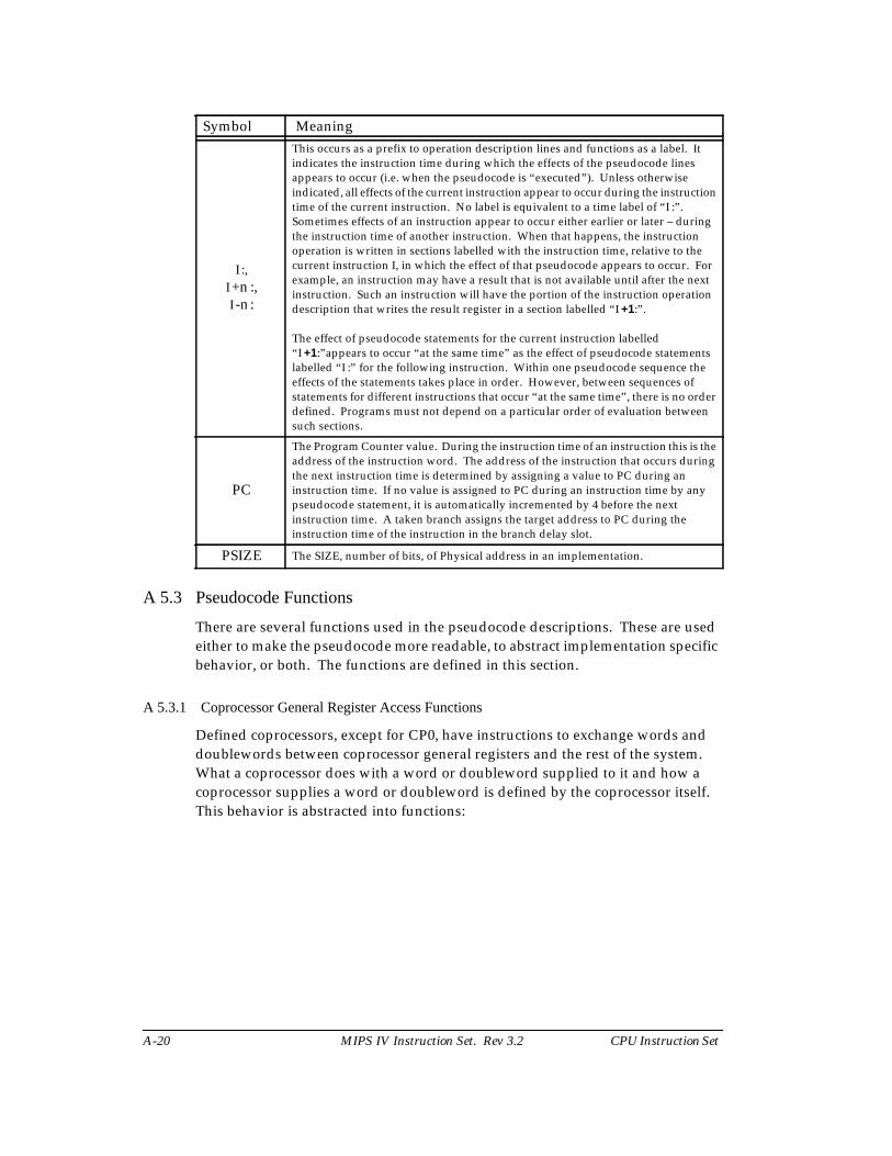
A 5.3 Pseudocode Functions
There are several functions used in the pseudocode descriptions. These are usedeither to make the pseudocode more readable, to abstract implementation specificbehavior, or both. The functions are defined in this section.
A 5.3.1 Coprocessor General Register Access Functions
Defined coprocessors, except for CP0, have instructions to exchange words anddoublewords between coprocessor general registers and the rest of the system.What a coprocessor does with a word or doubleword supplied to it and how acoprocessor supplies a word or doubleword is defined by the coprocessor itself.This behavior is abstracted into functions:
I :,I +n :,I -n :
This occurs as a prefix to operation description lines and functions as a label. Itindicates the instruction time during which the effects of the pseudocode linesappears to occur (i.e. when the pseudocode is “executed”). Unless otherwiseindicated, all effects of the current instruction appear to occur during the instructiontime of the current instruction. No label is equivalent to a time label of “I :”.Sometimes effects of an instruction appear to occur either earlier or later – duringthe instruction time of another instruction. When that happens, the instructionoperation is written in sections labelled with the instruction time, relative to thecurrent instruction I, in which the effect of that pseudocode appears to occur. Forexample, an instruction may have a result that is not available until after the nextinstruction. Such an instruction will have the portion of the instruction operationdescription that writes the result register in a section labelled “I +1:”.
The effect of pseudocode statements for the current instruction labelled“I +1:”appears to occur “at the same time” as the effect of pseudocode statementslabelled “I :” for the following instruction. Within one pseudocode sequence theeffects of the statements takes place in order. However, between sequences ofstatements for different instructions that occur “at the same time”, there is no orderdefined. Programs must not depend on a particular order of evaluation betweensuch sections.
PC
The Program Counter value. During the instruction time of an instruction this is theaddress of the instruction word. The address of the instruction that occurs duringthe next instruction time is determined by assigning a value to PC during aninstruction time. If no value is assigned to PC during an instruction time by anypseudocode statement, it is automatically incremented by 4 before the nextinstruction time. A taken branch assigns the target address to PC during theinstruction time of the instruction in the branch delay slot.
PSIZE The SIZE, number of bits, of Physical address in an implementation.
Symbol Meaning
CPU Instruction Set MIPS IV Instruction Set. Rev 3.2 A-21
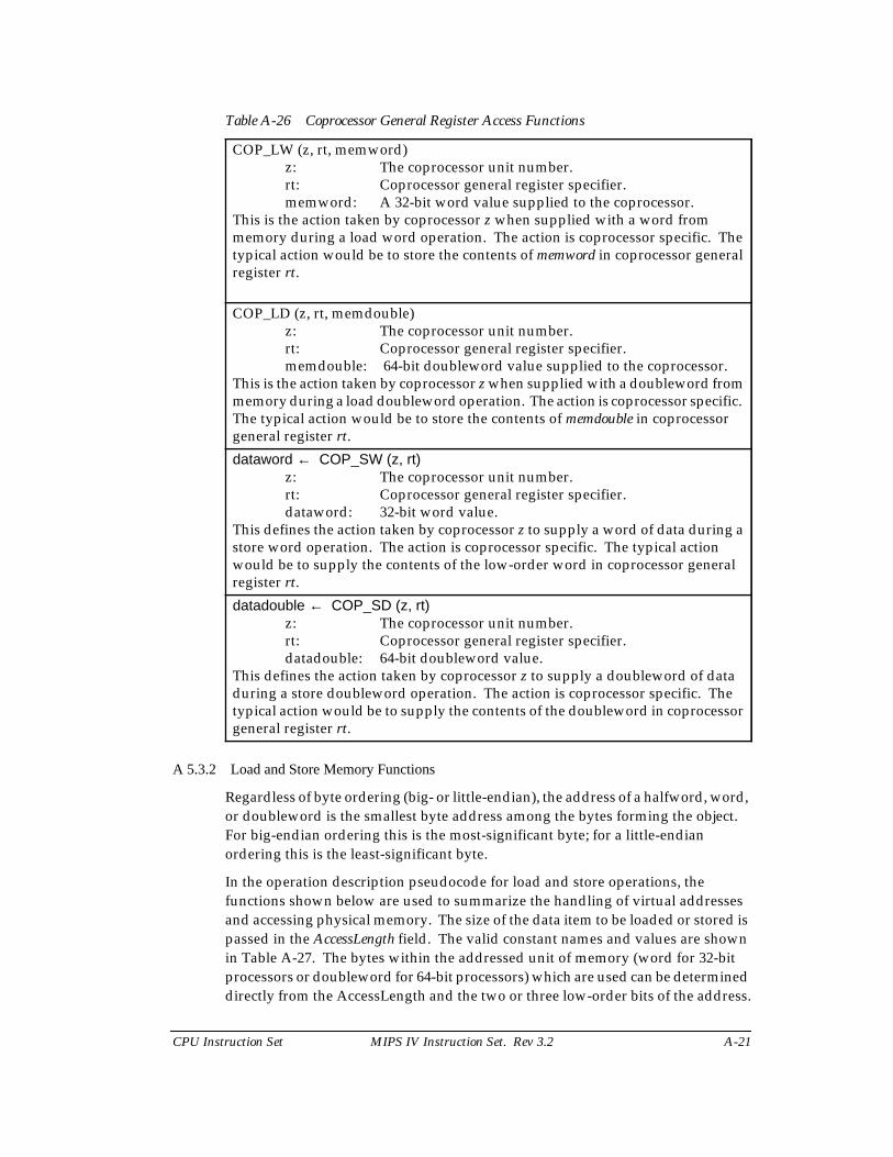
Table A-26 Coprocessor General Register Access Functions
A 5.3.2 Load and Store Memory Functions
Regardless of byte ordering (big- or little-endian), the address of a halfword, word,or doubleword is the smallest byte address among the bytes forming the object.For big-endian ordering this is the most-significant byte; for a little-endianordering this is the least-significant byte.
In the operation description pseudocode for load and store operations, thefunctions shown below are used to summarize the handling of virtual addressesand accessing physical memory. The size of the data item to be loaded or stored ispassed in the AccessLength field. The valid constant names and values are shownin Table A-27. The bytes within the addressed unit of memory (word for 32-bitprocessors or doubleword for 64-bit processors) which are used can be determineddirectly from the AccessLength and the two or three low-order bits of the address.
COP_LW (z, rt, memword)z: The coprocessor unit number.rt: Coprocessor general register specifier.memword: A 32-bit word value supplied to the coprocessor.
This is the action taken by coprocessor z when supplied with a word frommemory during a load word operation. The action is coprocessor specific. Thetypical action would be to store the contents of memword in coprocessor generalregister rt.
COP_LD (z, rt, memdouble)z: The coprocessor unit number.rt: Coprocessor general register specifier.memdouble: 64-bit doubleword value supplied to the coprocessor.
This is the action taken by coprocessor z when supplied with a doubleword frommemory during a load doubleword operation. The action is coprocessor specific.The typical action would be to store the contents of memdouble in coprocessorgeneral register rt.
dataword ← COP_SW (z, rt)z: The coprocessor unit number.rt: Coprocessor general register specifier.dataword: 32-bit word value.
This defines the action taken by coprocessor z to supply a word of data during astore word operation. The action is coprocessor specific. The typical actionwould be to supply the contents of the low-order word in coprocessor generalregister rt.
datadouble ← COP_SD (z, rt)z: The coprocessor unit number.rt: Coprocessor general register specifier.datadouble: 64-bit doubleword value.
This defines the action taken by coprocessor z to supply a doubleword of dataduring a store doubleword operation. The action is coprocessor specific. Thetypical action would be to supply the contents of the doubleword in coprocessorgeneral register rt.
A-22 MIPS IV Instruction Set. Rev 3.2 CPU Instruction Set
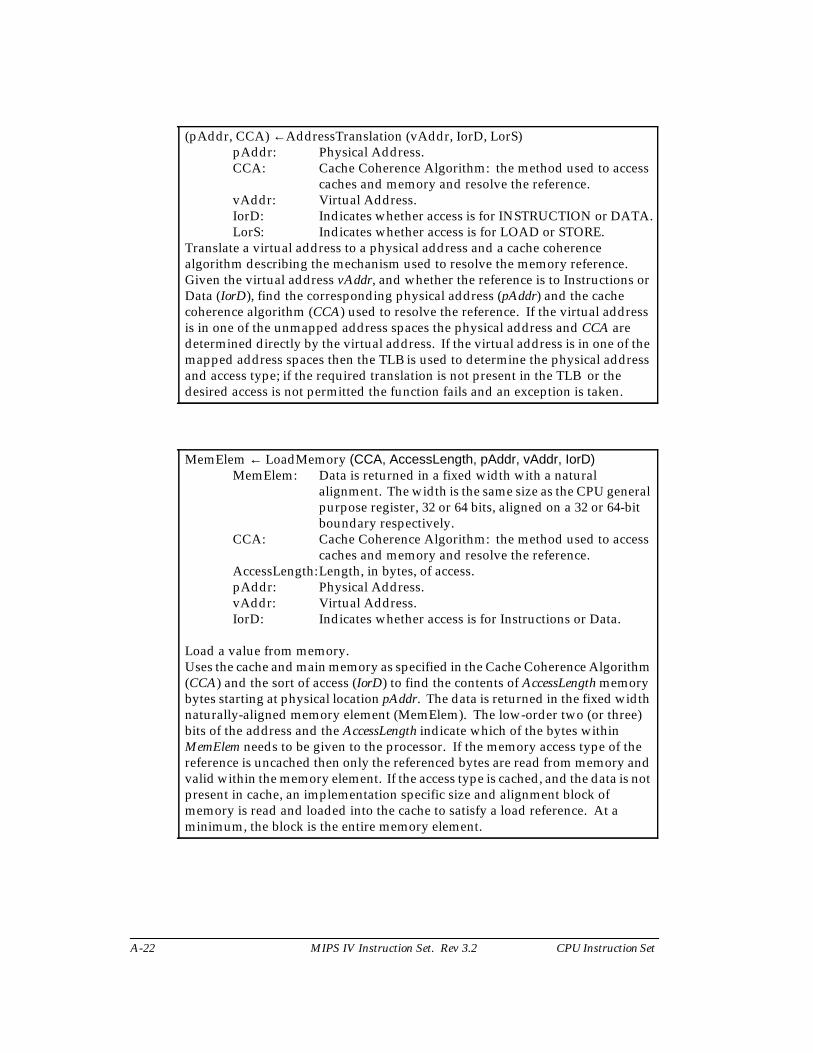
(pAddr, CCA) ←AddressTranslation (vAddr, IorD, LorS)pAddr: Physical Address.CCA: Cache Coherence Algorithm: the method used to access
caches and memory and resolve the reference.vAddr: Virtual Address.IorD: Indicates whether access is for INSTRUCTION or DATA.LorS: Indicates whether access is for LOAD or STORE.
Translate a virtual address to a physical address and a cache coherencealgorithm describing the mechanism used to resolve the memory reference.Given the virtual address vAddr, and whether the reference is to Instructions orData (IorD), find the corresponding physical address (pAddr) and the cachecoherence algorithm (CCA) used to resolve the reference. If the virtual addressis in one of the unmapped address spaces the physical address and CCA aredetermined directly by the virtual address. If the virtual address is in one of themapped address spaces then the TLB is used to determine the physical addressand access type; if the required translation is not present in the TLB or thedesired access is not permitted the function fails and an exception is taken.
MemElem ← LoadMemory (CCA, AccessLength, pAddr, vAddr, IorD)MemElem: Data is returned in a fixed width with a natural
alignment. The width is the same size as the CPU generalpurpose register, 32 or 64 bits, aligned on a 32 or 64-bitboundary respectively.
CCA: Cache Coherence Algorithm: the method used to accesscaches and memory and resolve the reference.
AccessLength:Length, in bytes, of access.pAddr: Physical Address.vAddr: Virtual Address.IorD: Indicates whether access is for Instructions or Data.
Load a value from memory.Uses the cache and main memory as specified in the Cache Coherence Algorithm(CCA) and the sort of access (IorD) to find the contents of AccessLength memorybytes starting at physical location pAddr. The data is returned in the fixed widthnaturally-aligned memory element (MemElem). The low-order two (or three)bits of the address and the AccessLength indicate which of the bytes withinMemElem needs to be given to the processor. If the memory access type of thereference is uncached then only the referenced bytes are read from memory andvalid within the memory element. If the access type is cached, and the data is notpresent in cache, an implementation specific size and alignment block ofmemory is read and loaded into the cache to satisfy a load reference. At aminimum, the block is the entire memory element.
CPU Instruction Set MIPS IV Instruction Set. Rev 3.2 A-23
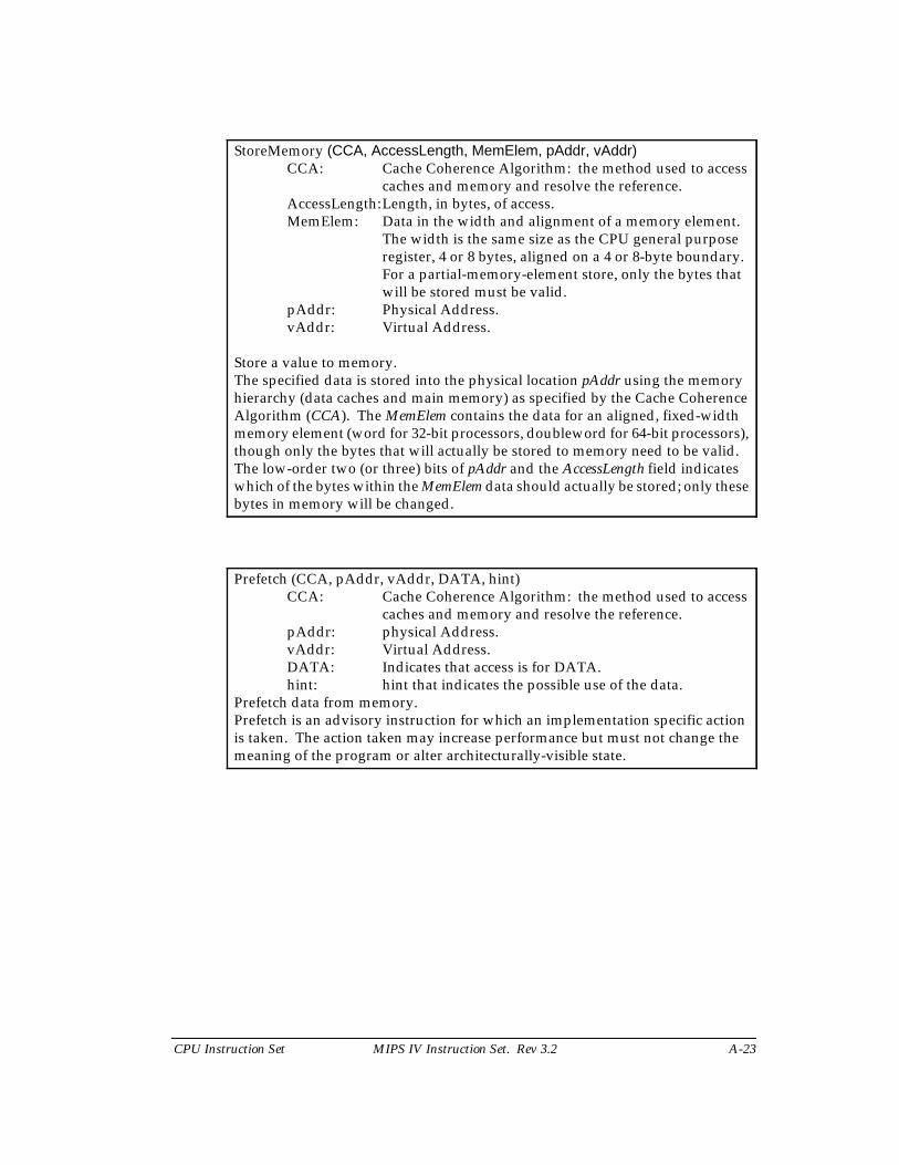
StoreMemory (CCA, AccessLength, MemElem, pAddr, vAddr)CCA: Cache Coherence Algorithm: the method used to access
caches and memory and resolve the reference.AccessLength:Length, in bytes, of access.MemElem: Data in the width and alignment of a memory element.
The width is the same size as the CPU general purposeregister, 4 or 8 bytes, aligned on a 4 or 8-byte boundary.For a partial-memory-element store, only the bytes thatwill be stored must be valid.
pAddr: Physical Address.vAddr: Virtual Address.
Store a value to memory.The specified data is stored into the physical location pAddr using the memoryhierarchy (data caches and main memory) as specified by the Cache CoherenceAlgorithm (CCA). The MemElem contains the data for an aligned, fixed-widthmemory element (word for 32-bit processors, doubleword for 64-bit processors),though only the bytes that will actually be stored to memory need to be valid.The low-order two (or three) bits of pAddr and the AccessLength field indicateswhich of the bytes within the MemElem data should actually be stored; only thesebytes in memory will be changed.
Prefetch (CCA, pAddr, vAddr, DATA, hint)CCA: Cache Coherence Algorithm: the method used to access
caches and memory and resolve the reference.pAddr: physical Address.vAddr: Virtual Address.DATA: Indicates that access is for DATA.hint: hint that indicates the possible use of the data.
Prefetch data from memory.Prefetch is an advisory instruction for which an implementation specific actionis taken. The action taken may increase performance but must not change themeaning of the program or alter architecturally-visible state.
A-24 MIPS IV Instruction Set. Rev 3.2 CPU Instruction Set
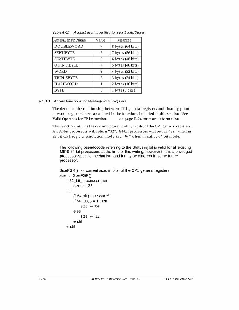
Table A-27 AccessLength Specifications for Loads/Stores
A 5.3.3 Access Functions for Floating-Point Registers
The details of the relationship between CP1 general registers and floating-pointoperand registers is encapsulated in the functions included in this section. SeeValid Operands for FP Instructions on page B-24 for more information.
This function returns the current logical width, in bits, of the CP1 general registers.All 32-bit processors will return “32”. 64-bit processors will return “32” when in32-bit-CP1-register emulation mode and “64” when in native 64-bit mode.
The following pseudocode referring to the StatusFR bit is valid for all existingMIPS 64-bit processors at the time of this writing, however this is a privilegedprocessor-specific mechanism and it may be different in some futureprocessor.
SizeFGR() -- current size, in bits, of the CP1 general registerssize ←SizeFGR()
if 32_bit_processor thensize ← 32
else/* 64-bit processor */if StatusFR = 1 then
size ← 64else
size ← 32endif
endif
AccessLength Name Value Meaning
DOUBLEWORD 7 8 bytes (64 bits)
SEPTIBYTE 6 7 bytes (56 bits)
SEXTIBYTE 5 6 bytes (48 bits)
QUINTIBYTE 4 5 bytes (40 bits)
WORD 3 4 bytes (32 bits)
TRIPLEBYTE 2 3 bytes (24 bits)
HALFWORD 1 2 bytes (16 bits)
BYTE 0 1 byte (8 bits)
CPU Instruction Set MIPS IV Instruction Set. Rev 3.2 A-25
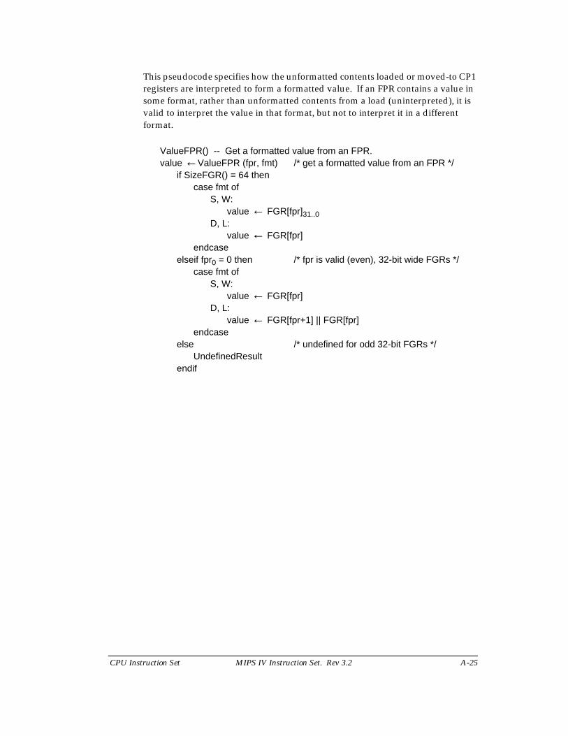
This pseudocode specifies how the unformatted contents loaded or moved-to CP1registers are interpreted to form a formatted value. If an FPR contains a value insome format, rather than unformatted contents from a load (uninterpreted), it isvalid to interpret the value in that format, but not to interpret it in a differentformat.
ValueFPR() -- Get a formatted value from an FPR.value ←ValueFPR (fpr, fmt) /* get a formatted value from an FPR */
if SizeFGR() = 64 thencase fmt of
S, W:value ← FGR[fpr]31..0
D, L:value ← FGR[fpr]
endcaseelseif fpr0 = 0 then /* fpr is valid (even), 32-bit wide FGRs */
case fmt ofS, W:
value ← FGR[fpr]D, L:
value ← FGR[fpr+1] || FGR[fpr]endcase
else /* undefined for odd 32-bit FGRs */UndefinedResult
endif
A-26 MIPS IV Instruction Set. Rev 3.2 CPU Instruction Set
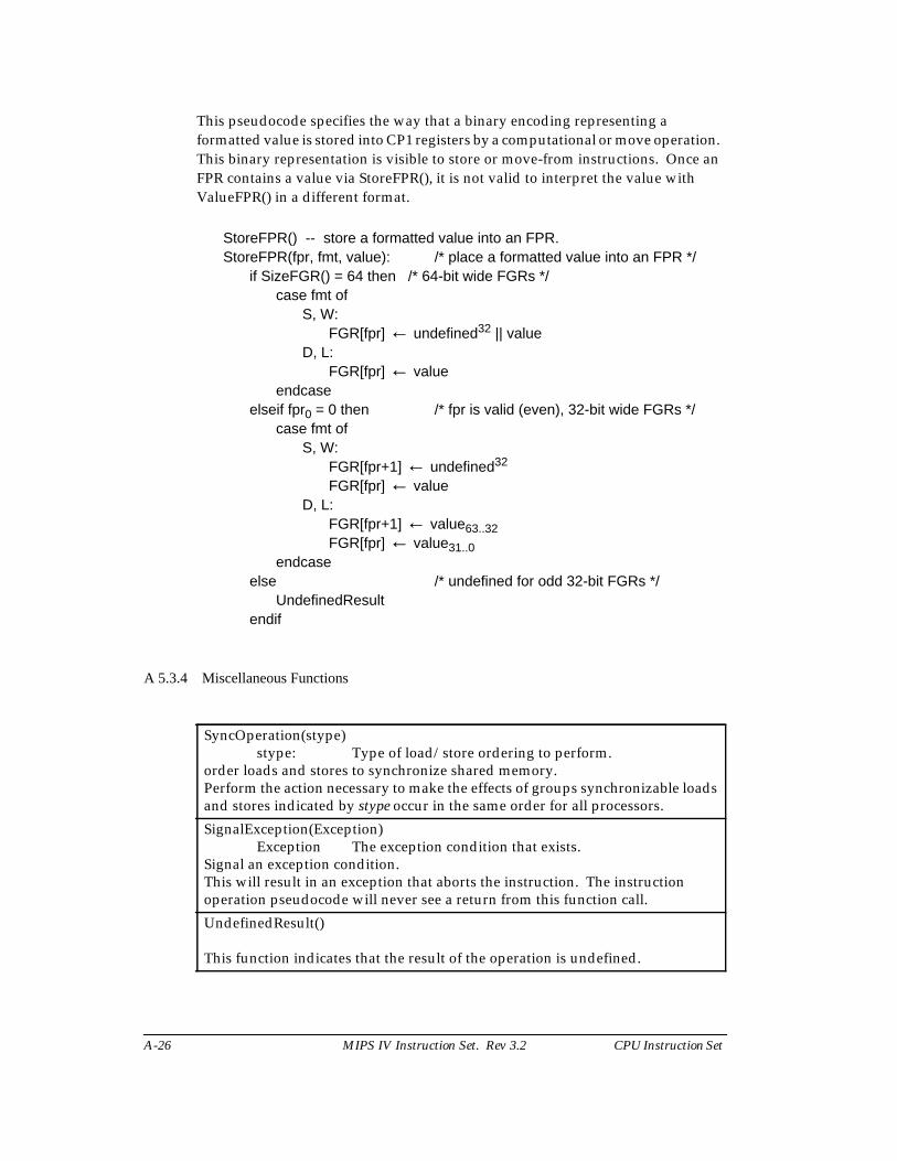
This pseudocode specifies the way that a binary encoding representing aformatted value is stored into CP1 registers by a computational or move operation.This binary representation is visible to store or move-from instructions. Once anFPR contains a value via StoreFPR(), it is not valid to interpret the value withValueFPR() in a different format.
StoreFPR() -- store a formatted value into an FPR.StoreFPR(fpr, fmt, value): /* place a formatted value into an FPR */
if SizeFGR() = 64 then /* 64-bit wide FGRs */case fmt of
S, W:FGR[fpr] ← undefined32 || value
D, L:FGR[fpr] ← value
endcaseelseif fpr0 = 0 then /* fpr is valid (even), 32-bit wide FGRs */
case fmt ofS, W:
FGR[fpr+1] ← undefined32
FGR[fpr] ← valueD, L:
FGR[fpr+1] ← value63..32FGR[fpr] ← value31..0
endcaseelse /* undefined for odd 32-bit FGRs */
UndefinedResultendif
A 5.3.4 Miscellaneous Functions
SyncOperation(stype)stype: Type of load/store ordering to perform.
order loads and stores to synchronize shared memory.Perform the action necessary to make the effects of groups synchronizable loadsand stores indicated by stype occur in the same order for all processors.
SignalException(Exception)Exception The exception condition that exists.
Signal an exception condition.This will result in an exception that aborts the instruction. The instructionoperation pseudocode will never see a return from this function call.
UndefinedResult()
This function indicates that the result of the operation is undefined.
CPU Instruction Set MIPS IV Instruction Set. Rev 3.2 A-27
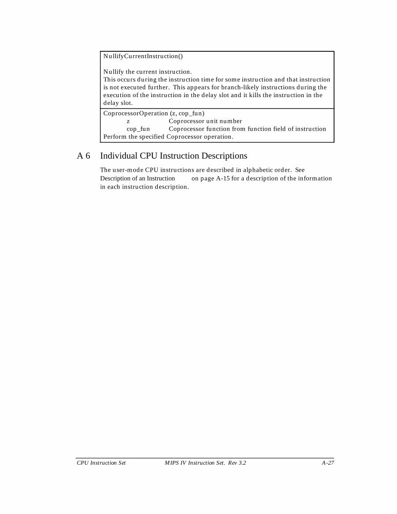
A 6 Individual CPU Instruction Descriptions
The user-mode CPU instructions are described in alphabetic order. SeeDescription of an Instruction on page A-15 for a description of the informationin each instruction description.
NullifyCurrentInstruction()
Nullify the current instruction.This occurs during the instruction time for some instruction and that instructionis not executed further. This appears for branch-likely instructions during theexecution of the instruction in the delay slot and it kills the instruction in thedelay slot.
CoprocessorOperation (z, cop_fun)z Coprocessor unit numbercop_fun Coprocessor function from function field of instruction
Perform the specified Coprocessor operation.
ADD Add Word
A-28 MIPS IV Instruction Set. Rev 3.2 CPU Instruction Set
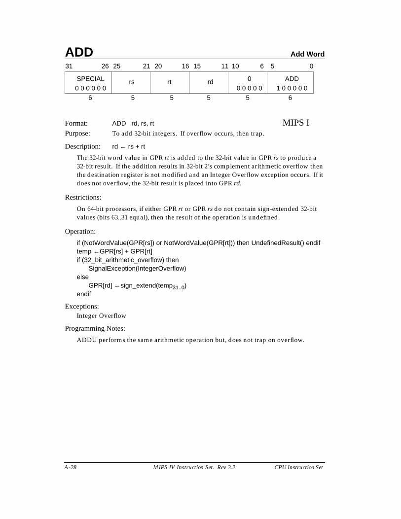
Format: ADD rd, rs, rt MIPS IPurpose: To add 32-bit integers. If overflow occurs, then trap.
Description: rd ← rs + rt
The 32-bit word value in GPR rt is added to the 32-bit value in GPR rs to produce a32-bit result. If the addition results in 32-bit 2’s complement arithmetic overflow thenthe destination register is not modified and an Integer Overflow exception occurs. If itdoes not overflow, the 32-bit result is placed into GPR rd.
Restrictions:
On 64-bit processors, if either GPR rt or GPR rs do not contain sign-extended 32-bitvalues (bits 63..31 equal), then the result of the operation is undefined.
Operation:
if (NotWordValue(GPR[rs]) or NotWordValue(GPR[rt])) then UndefinedResult() endiftemp ←GPR[rs] + GPR[rt]if (32_bit_arithmetic_overflow) then
SignalException(IntegerOverflow)else
GPR[rd] ←sign_extend(temp31..0)endif
Exceptions:Integer Overflow
Programming Notes:
ADDU performs the same arithmetic operation but, does not trap on overflow.
31 2526 2021 1516
SPECIAL rs rt
6 5 5
rd 0 ADD
5 5 6
11 10 6 5 0
0 0 0 0 0 0 0 0 0 0 0 1 0 0 0 0 0
Add Immediate Word ADDI
CPU Instruction Set MIPS IV Instruction Set. Rev 3.2 A-29
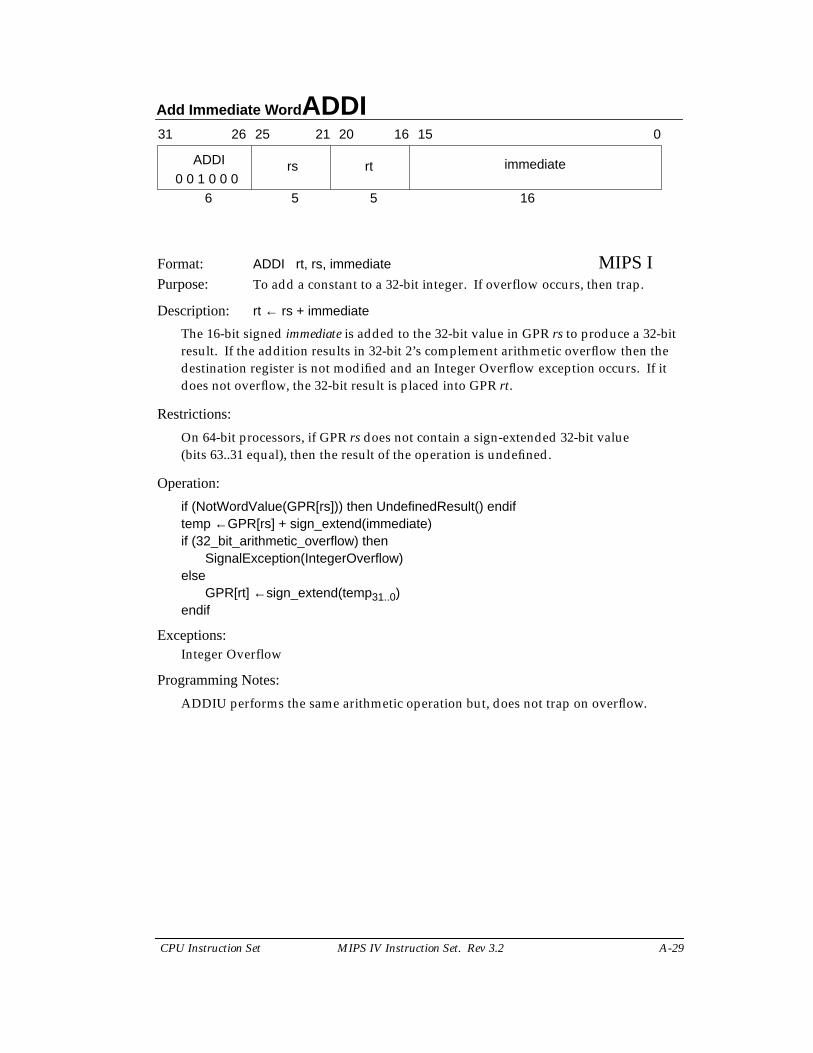
Format: ADDI rt, rs, immediate MIPS IPurpose: To add a constant to a 32-bit integer. If overflow occurs, then trap.
Description: rt ← rs + immediate
The 16-bit signed immediate is added to the 32-bit value in GPR rs to produce a 32-bitresult. If the addition results in 32-bit 2’s complement arithmetic overflow then thedestination register is not modified and an Integer Overflow exception occurs. If itdoes not overflow, the 32-bit result is placed into GPR rt.
Restrictions:
On 64-bit processors, if GPR rs does not contain a sign-extended 32-bit value(bits 63..31 equal), then the result of the operation is undefined.
Operation:
if (NotWordValue(GPR[rs])) then UndefinedResult() endiftemp ←GPR[rs] + sign_extend(immediate)if (32_bit_arithmetic_overflow) then
SignalException(IntegerOverflow)else
GPR[rt] ←sign_extend(temp31..0)endif
Exceptions:Integer Overflow
Programming Notes:
ADDIU performs the same arithmetic operation but, does not trap on overflow.
31 2526 2021 1516 0
ADDI rs rt immediate
6 5 5 160 0 1 0 0 0
ADDIU Add Immediate Unsigned Word
A-30 MIPS IV Instruction Set. Rev 3.2 CPU Instruction Set
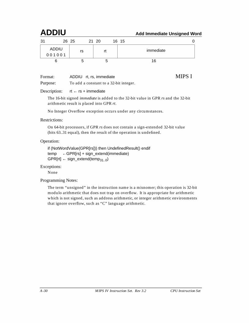
Format: ADDIU rt, rs, immediate MIPS IPurpose: To add a constant to a 32-bit integer.
Description: rt ← rs + immediate
The 16-bit signed immediate is added to the 32-bit value in GPR rs and the 32-bitarithmetic result is placed into GPR rt.
No Integer Overflow exception occurs under any circumstances.
Restrictions:
On 64-bit processors, if GPR rs does not contain a sign-extended 32-bit value(bits 63..31 equal), then the result of the operation is undefined.
Operation:
if (NotWordValue(GPR[rs])) then UndefinedResult() endiftemp ←GPR[rs] + sign_extend(immediate)GPR[rt] ← sign_extend(temp31..0)
Exceptions:None
Programming Notes:
The term “unsigned” in the instruction name is a misnomer; this operation is 32-bitmodulo arithmetic that does not trap on overflow. It is appropriate for arithmeticwhich is not signed, such as address arithmetic, or integer arithmetic environmentsthat ignore overflow, such as “C” language arithmetic.
31 2526 2021 1516 0
ADDIU rs rt immediate
6 5 5 160 0 1 0 0 1
Add Unsigned Word ADDU
CPU Instruction Set MIPS IV Instruction Set. Rev 3.2 A-31
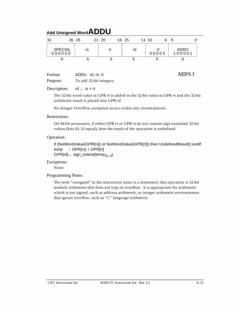
Format: ADDU rd, rs, rt MIPS IPurpose: To add 32-bit integers.
Description: rd ← rs + rt
The 32-bit word value in GPR rt is added to the 32-bit value in GPR rs and the 32-bitarithmetic result is placed into GPR rd.
No Integer Overflow exception occurs under any circumstances.
Restrictions:
On 64-bit processors, if either GPR rt or GPR rs do not contain sign-extended 32-bitvalues (bits 63..31 equal), then the result of the operation is undefined.
Operation:
if (NotWordValue(GPR[rs]) or NotWordValue(GPR[rt])) then UndefinedResult() endiftemp ←GPR[rs] + GPR[rt]GPR[rd]← sign_extend(temp31..0)
Exceptions:None
Programming Notes:
The term “unsigned” in the instruction name is a misnomer; this operation is 32-bitmodulo arithmetic that does not trap on overflow. It is appropriate for arithmeticwhich is not signed, such as address arithmetic, or integer arithmetic environmentsthat ignore overflow, such as “C” language arithmetic.
31 2526 2021 1516
SPECIAL rs rt
6 5 5
rd 0 ADDU
5 5 6
11 10 6 5 0
0 0 0 0 0 0 0 0 0 0 0 1 0 0 0 0 1
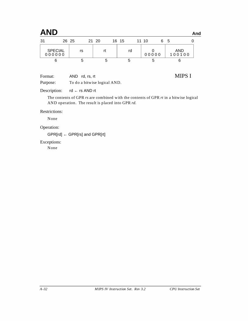
AND And
A-32 MIPS IV Instruction Set. Rev 3.2 CPU Instruction Set
Format: AND rd, rs, rt MIPS IPurpose: To do a bitwise logical AND.
Description: rd ← rs AND rt
The contents of GPR rs are combined with the contents of GPR rt in a bitwise logicalAND operation. The result is placed into GPR rd.
Restrictions:
None
Operation:
GPR[rd] ← GPR[rs] and GPR[rt]
Exceptions:None
31 2526 2021 1516
SPECIAL rs rt
6 5 5
rd 0 AND
5 5 6
11 10 6 5 0
0 0 0 0 0 0 0 0 0 0 0 1 0 0 1 0 0
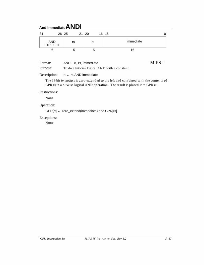
And Immediate ANDI
CPU Instruction Set MIPS IV Instruction Set. Rev 3.2 A-33
Format: ANDI rt, rs, immediate MIPS IPurpose: To do a bitwise logical AND with a constant.
Description: rt ← rs AND immediate
The 16-bit immediate is zero-extended to the left and combined with the contents ofGPR rs in a bitwise logical AND operation. The result is placed into GPR rt.
Restrictions:
None
Operation:
GPR[rt] ← zero_extend(immediate) and GPR[rs]
Exceptions:None
31 2526 2021 1516 0
ANDI rs rt immediate
6 5 5 160 0 1 1 0 0
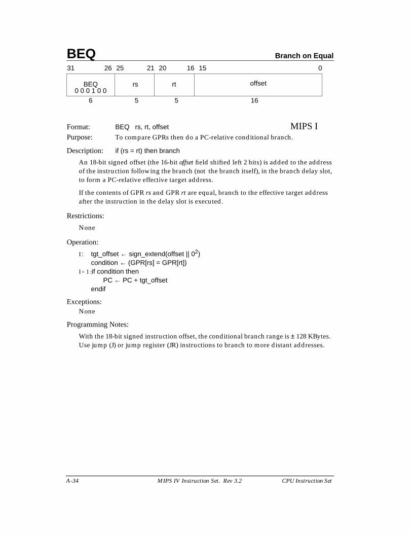
BEQ Branch on Equal
A-34 MIPS IV Instruction Set. Rev 3.2 CPU Instruction Set
Format: BEQ rs, rt, offset MIPS IPurpose: To compare GPRs then do a PC-relative conditional branch.
Description: if (rs = rt) then branch
An 18-bit signed offset (the 16-bit offset field shifted left 2 bits) is added to the addressof the instruction following the branch (not the branch itself), in the branch delay slot,to form a PC-relative effective target address.
If the contents of GPR rs and GPR rt are equal, branch to the effective target addressafter the instruction in the delay slot is executed.
Restrictions:
None
Operation:
I : tgt_offset ← sign_extend(offset || 02)condition ← (GPR[rs] = GPR[rt])
I + 1 :if condition thenPC ← PC + tgt_offset
endif
Exceptions:None
Programming Notes:
With the 18-bit signed instruction offset, the conditional branch range is ± 128 KBytes.Use jump (J) or jump register (JR) instructions to branch to more distant addresses.
31 2526 2021 1516 0
BEQ rs rt offset
6 5 5 160 0 0 1 0 0
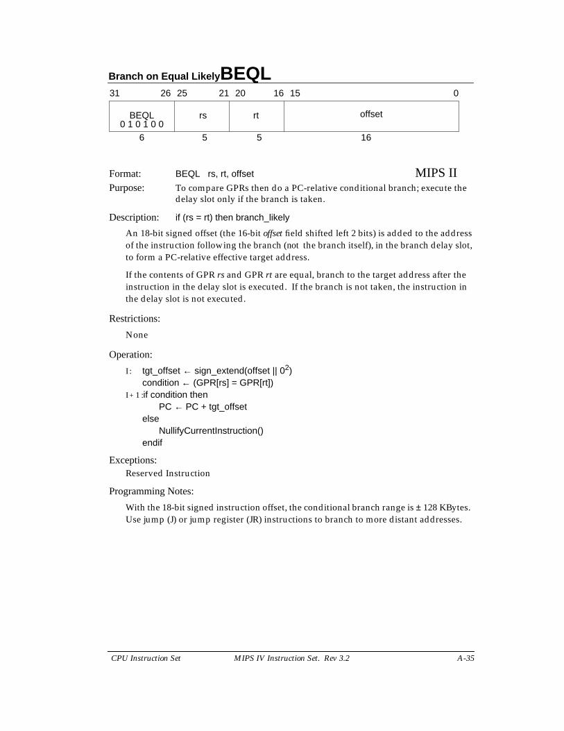
Branch on Equal Likely BEQL
CPU Instruction Set MIPS IV Instruction Set. Rev 3.2 A-35
Format: BEQL rs, rt, offset MIPS IIPurpose: To compare GPRs then do a PC-relative conditional branch; execute the
delay slot only if the branch is taken.
Description: if (rs = rt) then branch_likely
An 18-bit signed offset (the 16-bit offset field shifted left 2 bits) is added to the addressof the instruction following the branch (not the branch itself), in the branch delay slot,to form a PC-relative effective target address.
If the contents of GPR rs and GPR rt are equal, branch to the target address after theinstruction in the delay slot is executed. If the branch is not taken, the instruction inthe delay slot is not executed.
Restrictions:
None
Operation:
I : tgt_offset ← sign_extend(offset || 02)condition ← (GPR[rs] = GPR[rt])
I + 1 :if condition thenPC ← PC + tgt_offset
elseNullifyCurrentInstruction()
endif
Exceptions:Reserved Instruction
Programming Notes:
With the 18-bit signed instruction offset, the conditional branch range is ± 128 KBytes.Use jump (J) or jump register (JR) instructions to branch to more distant addresses.
31 2526 2021 1516 0
BEQL rs rt offset
6 5 5 160 1 0 1 0 0
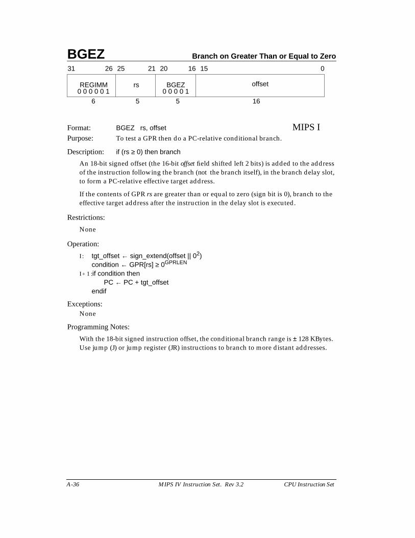
BGEZ Branch on Greater Than or Equal to Zero
A-36 MIPS IV Instruction Set. Rev 3.2 CPU Instruction Set
Format: BGEZ rs, offset MIPS IPurpose: To test a GPR then do a PC-relative conditional branch.
Description: if (rs ≥ 0) then branch
An 18-bit signed offset (the 16-bit offset field shifted left 2 bits) is added to the addressof the instruction following the branch (not the branch itself), in the branch delay slot,to form a PC-relative effective target address.
If the contents of GPR rs are greater than or equal to zero (sign bit is 0), branch to theeffective target address after the instruction in the delay slot is executed.
Restrictions:
None
Operation:
I : tgt_offset ← sign_extend(offset || 02)condition ← GPR[rs] ≥ 0GPRLEN
I + 1 :if condition thenPC ← PC + tgt_offset
endif
Exceptions:None
Programming Notes:
With the 18-bit signed instruction offset, the conditional branch range is ± 128 KBytes.Use jump (J) or jump register (JR) instructions to branch to more distant addresses.
31 2526 2021 1516 0
REGIMM rs BGEZ offset
6 5 5 160 0 0 0 0 1 0 0 0 0 1
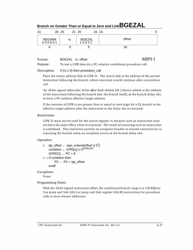
Branch on Greater Than or Equal to Zero and Link BGEZAL
CPU Instruction Set MIPS IV Instruction Set. Rev 3.2 A-37
Format: BGEZAL rs, offset MIPS IPurpose: To test a GPR then do a PC-relative conditional procedure call.
Description: if (rs ≥ 0) then procedure_call
Place the return address link in GPR 31. The return link is the address of the secondinstruction following the branch, where execution would continue after a procedurecall.
An 18-bit signed offset (the 16-bit offset field shifted left 2 bits) is added to the addressof the instruction following the branch (not the branch itself), in the branch delay slot,to form a PC-relative effective target address.
If the contents of GPR rs are greater than or equal to zero (sign bit is 0), branch to theeffective target address after the instruction in the delay slot is executed.
Restrictions:
GPR 31 must not be used for the source register rs, because such an instruction doesnot have the same effect when re-executed. The result of executing such an instructionis undefined. This restriction permits an exception handler to resume execution by re-executing the branch when an exception occurs in the branch delay slot.
Operation:
I : tgt_offset ← sign_extend(offset || 02)condition ← GPR[rs] ≥ 0GPRLEN
GPR[31] ← PC + 8I + 1 :if condition then
PC ← PC + tgt_offsetendif
Exceptions:None
Programming Notes:
With the 18-bit signed instruction offset, the conditional branch range is ± 128 KBytes.Use jump and link (JAL) or jump and link register (JALR) instructions for procedurecalls to more distant addresses.
31 2526 2021 1516 0
REGIMM rs BGEZAL offset
6 5 5 160 0 0 0 0 1 1 0 0 0 1
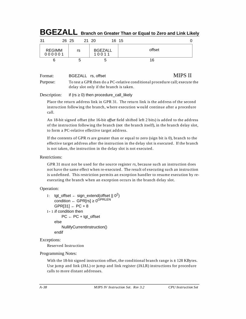
BGEZALL Branch on Greater Than or Equal to Zero and Link Likely
A-38 MIPS IV Instruction Set. Rev 3.2 CPU Instruction Set
Format: BGEZALL rs, offset MIPS IIPurpose: To test a GPR then do a PC-relative conditional procedure call; execute the
delay slot only if the branch is taken.
Description: if (rs ≥ 0) then procedure_call_likely
Place the return address link in GPR 31. The return link is the address of the secondinstruction following the branch, where execution would continue after a procedurecall.
An 18-bit signed offset (the 16-bit offset field shifted left 2 bits) is added to the addressof the instruction following the branch (not the branch itself), in the branch delay slot,to form a PC-relative effective target address.
If the contents of GPR rs are greater than or equal to zero (sign bit is 0), branch to theeffective target address after the instruction in the delay slot is executed. If the branchis not taken, the instruction in the delay slot is not executed.
Restrictions:
GPR 31 must not be used for the source register rs, because such an instruction doesnot have the same effect when re-executed. The result of executing such an instructionis undefined. This restriction permits an exception handler to resume execution by re-executing the branch when an exception occurs in the branch delay slot.
Operation:
I : tgt_offset ← sign_extend(offset || 02)condition ← GPR[rs] ≥ 0GPRLEN
GPR[31] ← PC + 8I + 1 :if condition then
PC ← PC + tgt_offsetelse
NullifyCurrentInstruction()endif
Exceptions:Reserved Instruction
Programming Notes:
With the 18-bit signed instruction offset, the conditional branch range is ± 128 KBytes.Use jump and link (JAL) or jump and link register (JALR) instructions for procedurecalls to more distant addresses.
31 2526 2021 1516 0
REGIMM rs BGEZALL offset
6 5 5 160 0 0 0 0 1 1 0 0 1 1
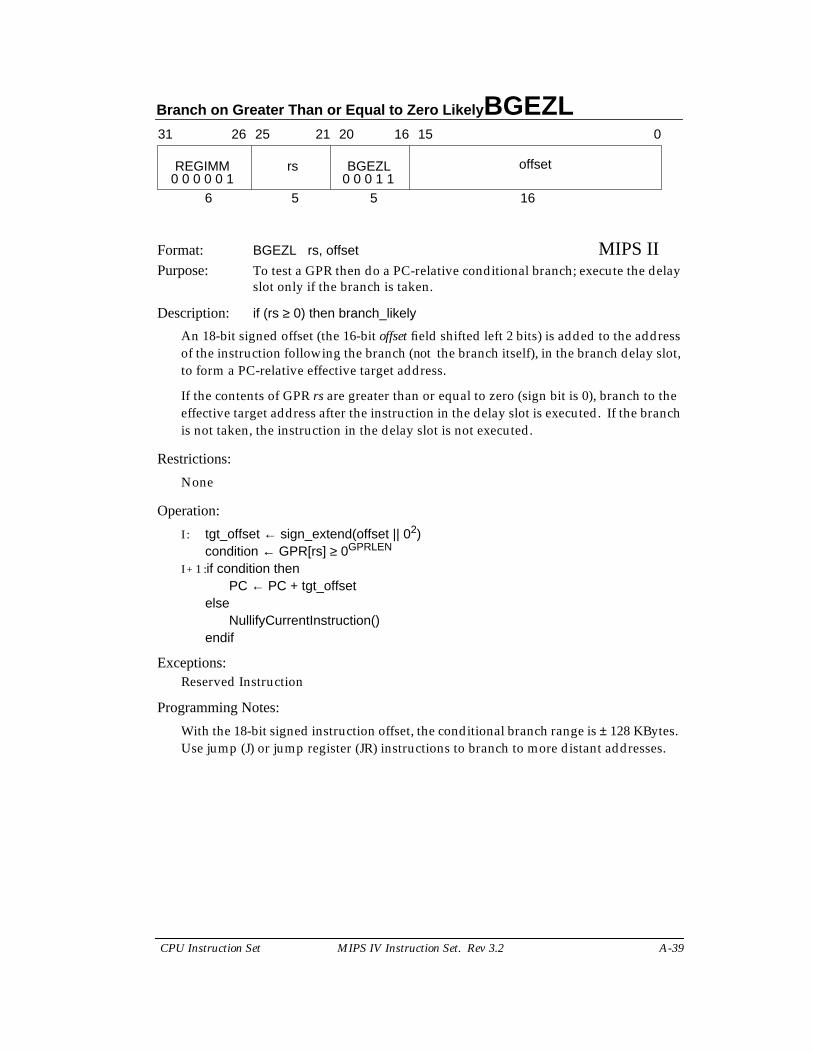
Branch on Greater Than or Equal to Zero Likely BGEZL
CPU Instruction Set MIPS IV Instruction Set. Rev 3.2 A-39
Format: BGEZL rs, offset MIPS IIPurpose: To test a GPR then do a PC-relative conditional branch; execute the delay
slot only if the branch is taken.
Description: if (rs ≥ 0) then branch_likely
An 18-bit signed offset (the 16-bit offset field shifted left 2 bits) is added to the addressof the instruction following the branch (not the branch itself), in the branch delay slot,to form a PC-relative effective target address.
If the contents of GPR rs are greater than or equal to zero (sign bit is 0), branch to theeffective target address after the instruction in the delay slot is executed. If the branchis not taken, the instruction in the delay slot is not executed.
Restrictions:
None
Operation:
I : tgt_offset ← sign_extend(offset || 02)condition ← GPR[rs] ≥ 0GPRLEN
I + 1 :if condition thenPC ← PC + tgt_offset
elseNullifyCurrentInstruction()
endif
Exceptions:Reserved Instruction
Programming Notes:
With the 18-bit signed instruction offset, the conditional branch range is ± 128 KBytes.Use jump (J) or jump register (JR) instructions to branch to more distant addresses.
31 2526 2021 1516 0
REGIMM rs BGEZL offset
6 5 5 160 0 0 0 0 1 0 0 0 1 1
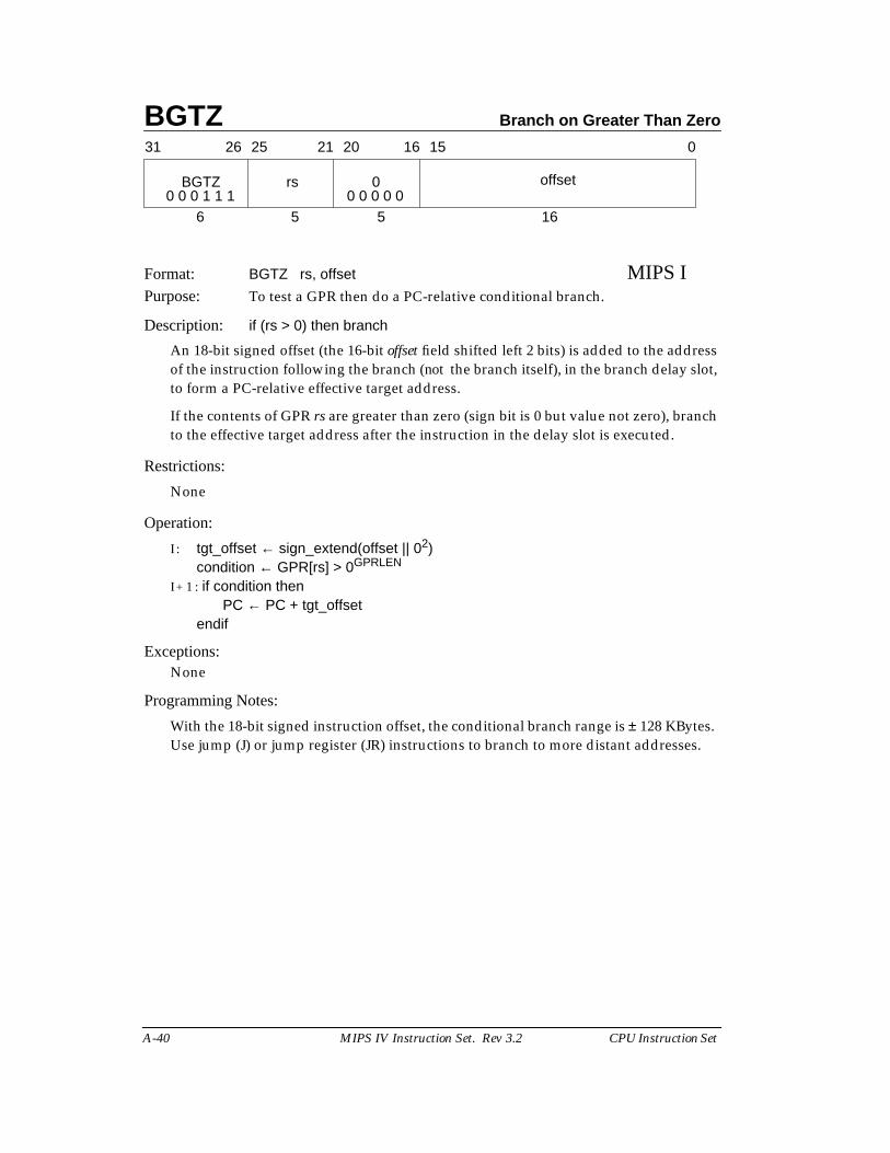
BGTZ Branch on Greater Than Zero
A-40 MIPS IV Instruction Set. Rev 3.2 CPU Instruction Set
Format: BGTZ rs, offset MIPS IPurpose: To test a GPR then do a PC-relative conditional branch.
Description: if (rs > 0) then branch
An 18-bit signed offset (the 16-bit offset field shifted left 2 bits) is added to the addressof the instruction following the branch (not the branch itself), in the branch delay slot,to form a PC-relative effective target address.
If the contents of GPR rs are greater than zero (sign bit is 0 but value not zero), branchto the effective target address after the instruction in the delay slot is executed.
Restrictions:
None
Operation:
I : tgt_offset ← sign_extend(offset || 02)condition ← GPR[rs] > 0GPRLEN
I + 1 : if condition thenPC ← PC + tgt_offset
endif
Exceptions:None
Programming Notes:
With the 18-bit signed instruction offset, the conditional branch range is ± 128 KBytes.Use jump (J) or jump register (JR) instructions to branch to more distant addresses.
31 2526 2021 1516 0
BGTZ rs 0 offset
6 5 5 160 0 0 1 1 1 0 0 0 0 0
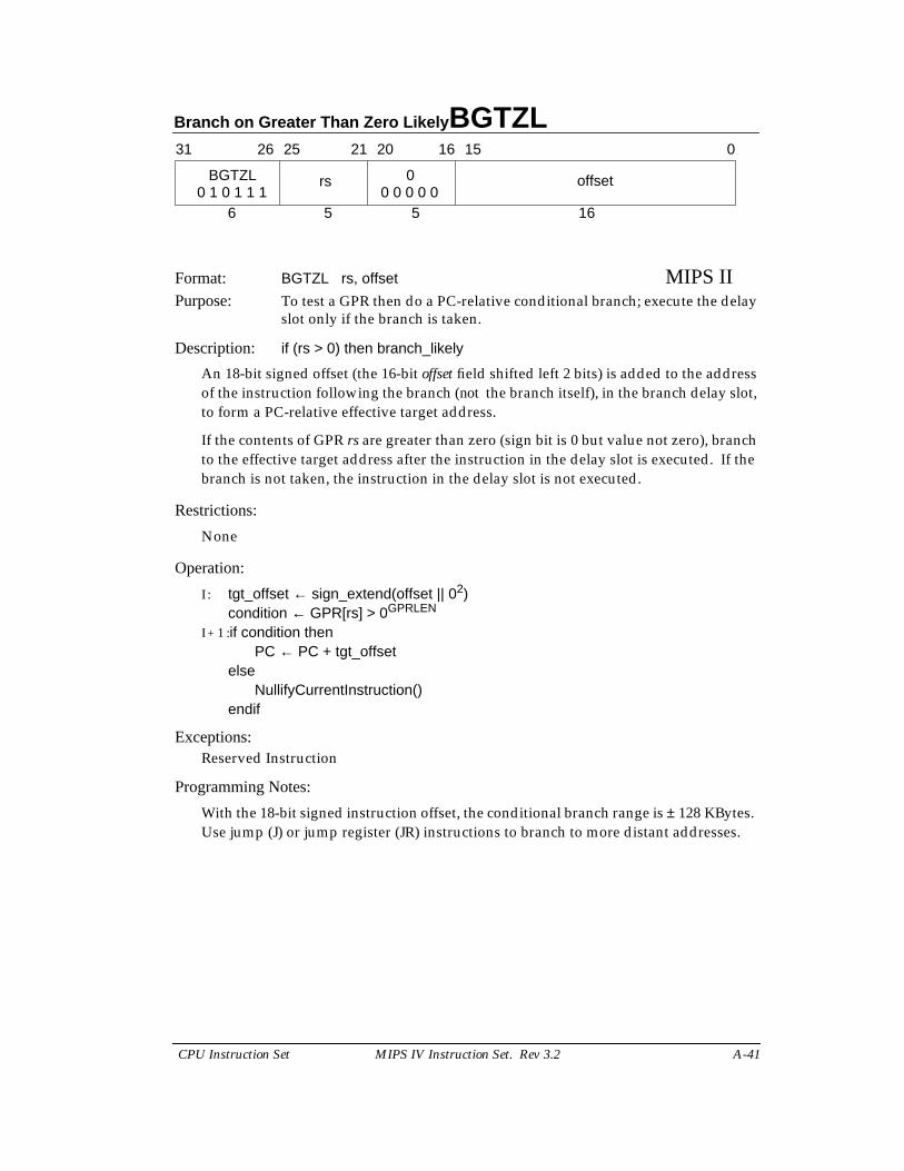
Branch on Greater Than Zero Likely BGTZL
CPU Instruction Set MIPS IV Instruction Set. Rev 3.2 A-41
Format: BGTZL rs, offset MIPS IIPurpose: To test a GPR then do a PC-relative conditional branch; execute the delay
slot only if the branch is taken.
Description: if (rs > 0) then branch_likely
An 18-bit signed offset (the 16-bit offset field shifted left 2 bits) is added to the addressof the instruction following the branch (not the branch itself), in the branch delay slot,to form a PC-relative effective target address.
If the contents of GPR rs are greater than zero (sign bit is 0 but value not zero), branchto the effective target address after the instruction in the delay slot is executed. If thebranch is not taken, the instruction in the delay slot is not executed.
Restrictions:
None
Operation:
I : tgt_offset ← sign_extend(offset || 02)condition ← GPR[rs] > 0GPRLEN
I + 1 :if condition thenPC ← PC + tgt_offset
elseNullifyCurrentInstruction()
endif
Exceptions:Reserved Instruction
Programming Notes:
With the 18-bit signed instruction offset, the conditional branch range is ± 128 KBytes.Use jump (J) or jump register (JR) instructions to branch to more distant addresses.
31 2526 2021 1516 0
BGTZL rs 0 offset
6 5 5 160 1 0 1 1 1 0 0 0 0 0
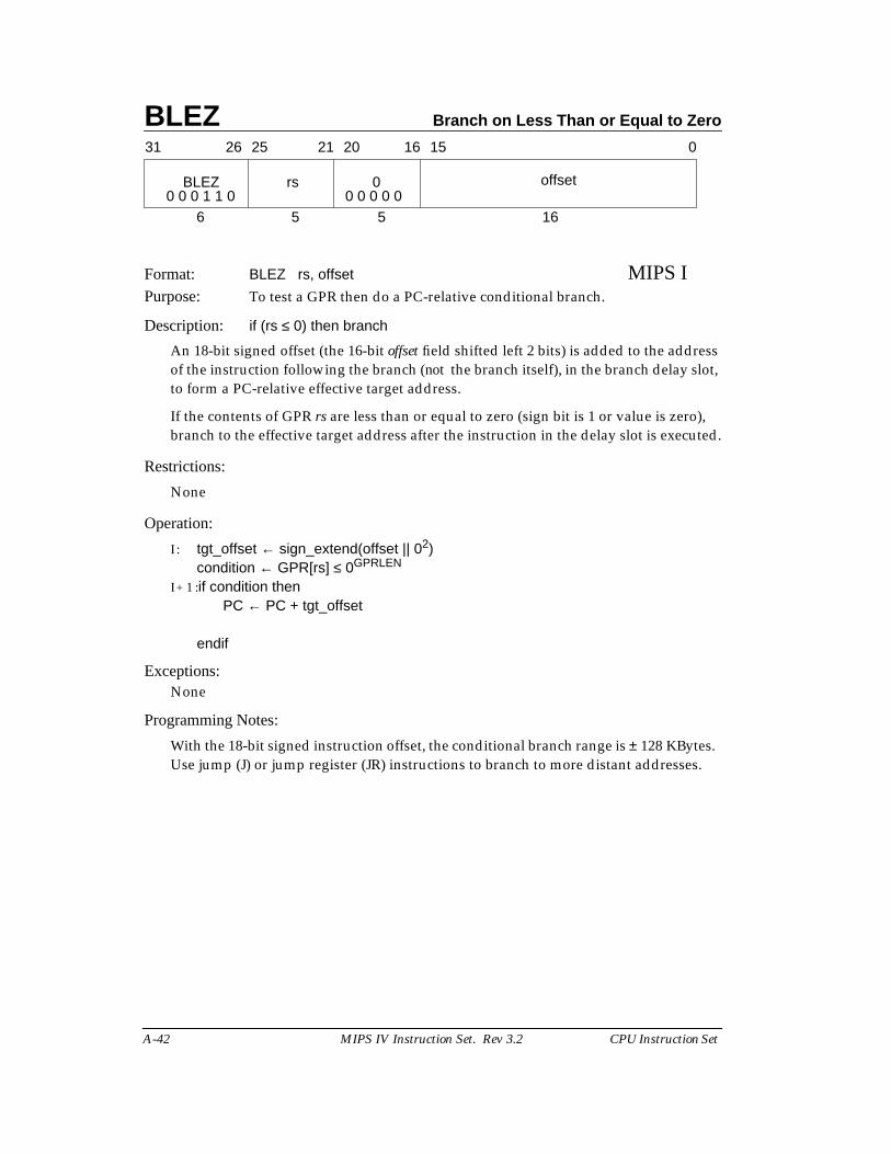
BLEZ Branch on Less Than or Equal to Zero
A-42 MIPS IV Instruction Set. Rev 3.2 CPU Instruction Set
Format: BLEZ rs, offset MIPS IPurpose: To test a GPR then do a PC-relative conditional branch.
Description: if (rs ≤ 0) then branch
An 18-bit signed offset (the 16-bit offset field shifted left 2 bits) is added to the addressof the instruction following the branch (not the branch itself), in the branch delay slot,to form a PC-relative effective target address.
If the contents of GPR rs are less than or equal to zero (sign bit is 1 or value is zero),branch to the effective target address after the instruction in the delay slot is executed.
Restrictions:
None
Operation:
I : tgt_offset ← sign_extend(offset || 02)condition ← GPR[rs] ≤ 0GPRLEN
I + 1 :if condition thenPC ← PC + tgt_offset
endif
Exceptions:None
Programming Notes:
With the 18-bit signed instruction offset, the conditional branch range is ± 128 KBytes.Use jump (J) or jump register (JR) instructions to branch to more distant addresses.
31 2526 2021 1516 0
BLEZ rs 0 offset
6 5 5 160 0 0 1 1 0 0 0 0 0 0
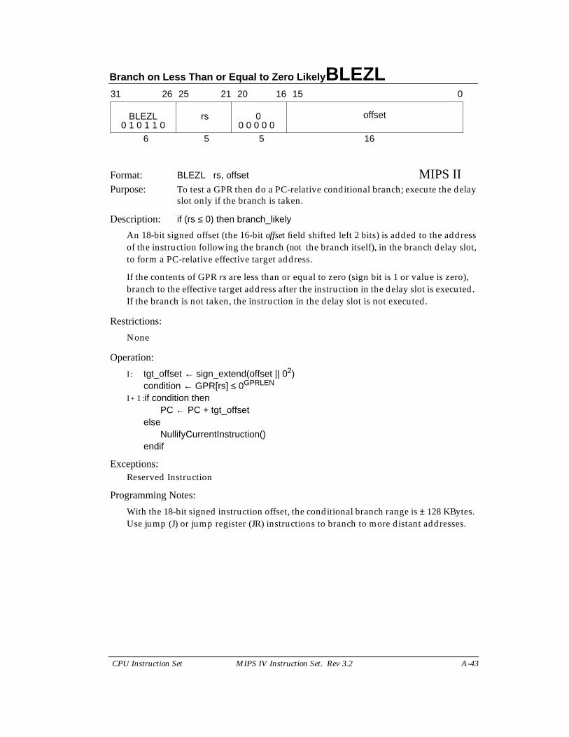
Branch on Less Than or Equal to Zero Likely BLEZL
CPU Instruction Set MIPS IV Instruction Set. Rev 3.2 A-43
Format: BLEZL rs, offset MIPS IIPurpose: To test a GPR then do a PC-relative conditional branch; execute the delay
slot only if the branch is taken.
Description: if (rs ≤ 0) then branch_likely
An 18-bit signed offset (the 16-bit offset field shifted left 2 bits) is added to the addressof the instruction following the branch (not the branch itself), in the branch delay slot,to form a PC-relative effective target address.
If the contents of GPR rs are less than or equal to zero (sign bit is 1 or value is zero),branch to the effective target address after the instruction in the delay slot is executed.If the branch is not taken, the instruction in the delay slot is not executed.
Restrictions:
None
Operation:
I : tgt_offset ← sign_extend(offset || 02)condition ← GPR[rs] ≤ 0GPRLEN
I + 1 :if condition thenPC ← PC + tgt_offset
elseNullifyCurrentInstruction()
endif
Exceptions:Reserved Instruction
Programming Notes:
With the 18-bit signed instruction offset, the conditional branch range is ± 128 KBytes.Use jump (J) or jump register (JR) instructions to branch to more distant addresses.
31 2526 2021 1516 0
BLEZL rs 0 offset
6 5 5 160 1 0 1 1 0 0 0 0 0 0

BLTZ Branch on Less Than Zero
A-44 MIPS IV Instruction Set. Rev 3.2 CPU Instruction Set
Format: BLTZ rs, offset MIPS IPurpose: To test a GPR then do a PC-relative conditional branch.
Description: if (rs < 0) then branch
An 18-bit signed offset (the 16-bit offset field shifted left 2 bits) is added to the addressof the instruction following the branch (not the branch itself), in the branch delay slot,to form a PC-relative effective target address.
If the contents of GPR rs are less than zero (sign bit is 1), branch to the effective targetaddress after the instruction in the delay slot is executed.
Restrictions:
None
Operation:
I : tgt_offset ← sign_extend(offset || 02)condition ← GPR[rs] < 0GPRLEN
I + 1 :if condition thenPC ← PC + tgt_offset
endif
Exceptions:None
Programming Notes:
With the 18-bit signed instruction offset, the conditional branch range is ± 128 KBytes.Use jump (J) or jump register (JR) instructions to branch to more distant addresses.
31 2526 2021 1516 0
REGIMM rs BLTZ offset
6 5 5 160 0 0 0 0 1 0 0 0 0 0
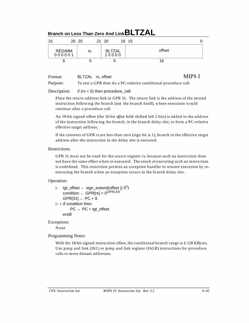
Branch on Less Than Zero And Link BLTZAL
CPU Instruction Set MIPS IV Instruction Set. Rev 3.2 A-45
Format: BLTZAL rs, offset MIPS IPurpose: To test a GPR then do a PC-relative conditional procedure call.
Description: if (rs < 0) then procedure_call
Place the return address link in GPR 31. The return link is the address of the secondinstruction following the branch (not the branch itself), where execution wouldcontinue after a procedure call.
An 18-bit signed offset (the 16-bit offset field shifted left 2 bits) is added to the addressof the instruction following the branch, in the branch delay slot, to form a PC-relativeeffective target address.
If the contents of GPR rs are less than zero (sign bit is 1), branch to the effective targetaddress after the instruction in the delay slot is executed.
Restrictions:
GPR 31 must not be used for the source register rs, because such an instruction doesnot have the same effect when re-executed. The result of executing such an instructionis undefined. This restriction permits an exception handler to resume execution by re-executing the branch when an exception occurs in the branch delay slot.
Operation:
I : tgt_offset ← sign_extend(offset || 02)condition ← GPR[rs] < 0GPRLEN
GPR[31] ← PC + 8I + 1 :if condition then
PC ← PC + tgt_offsetendif
Exceptions:None
Programming Notes:
With the 18-bit signed instruction offset, the conditional branch range is ± 128 KBytes.Use jump and link (JAL) or jump and link register (JALR) instructions for procedurecalls to more distant addresses.
31 2526 2021 1516 0
REGIMM rs BLTZAL offset
6 5 5 160 0 0 0 0 1 1 0 0 0 0
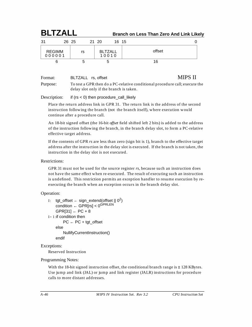
BLTZALL Branch on Less Than Zero And Link Likely
A-46 MIPS IV Instruction Set. Rev 3.2 CPU Instruction Set
Format: BLTZALL rs, offset MIPS IIPurpose: To test a GPR then do a PC-relative conditional procedure call; execute the
delay slot only if the branch is taken.
Description: if (rs < 0) then procedure_call_likely
Place the return address link in GPR 31. The return link is the address of the secondinstruction following the branch (not the branch itself), where execution wouldcontinue after a procedure call.
An 18-bit signed offset (the 16-bit offset field shifted left 2 bits) is added to the addressof the instruction following the branch, in the branch delay slot, to form a PC-relativeeffective target address.
If the contents of GPR rs are less than zero (sign bit is 1), branch to the effective targetaddress after the instruction in the delay slot is executed. If the branch is not taken, theinstruction in the delay slot is not executed.
Restrictions:
GPR 31 must not be used for the source register rs, because such an instruction doesnot have the same effect when re-executed. The result of executing such an instructionis undefined. This restriction permits an exception handler to resume execution by re-executing the branch when an exception occurs in the branch delay slot.
Operation:
I : tgt_offset ← sign_extend(offset || 02)condition ← GPR[rs] < 0GPRLEN
GPR[31] ← PC + 8I + 1 :if condition then
PC ← PC + tgt_offsetelse
NullifyCurrentInstruction()endif
Exceptions:Reserved Instruction
Programming Notes:
With the 18-bit signed instruction offset, the conditional branch range is ± 128 KBytes.Use jump and link (JAL) or jump and link register (JALR) instructions for procedurecalls to more distant addresses.
31 2526 2021 1516 0
REGIMM rs BLTZALL offset
6 5 5 160 0 0 0 0 1 1 0 0 1 0
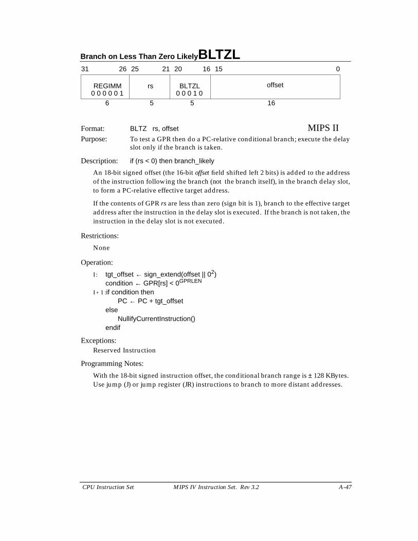
Branch on Less Than Zero Likely BLTZL
CPU Instruction Set MIPS IV Instruction Set. Rev 3.2 A-47
Format: BLTZ rs, offset MIPS IIPurpose: To test a GPR then do a PC-relative conditional branch; execute the delay
slot only if the branch is taken.
Description: if (rs < 0) then branch_likely
An 18-bit signed offset (the 16-bit offset field shifted left 2 bits) is added to the addressof the instruction following the branch (not the branch itself), in the branch delay slot,to form a PC-relative effective target address.
If the contents of GPR rs are less than zero (sign bit is 1), branch to the effective targetaddress after the instruction in the delay slot is executed. If the branch is not taken, theinstruction in the delay slot is not executed.
Restrictions:
None
Operation:
I : tgt_offset ← sign_extend(offset || 02)condition ← GPR[rs] < 0GPRLEN
I + 1 :if condition thenPC ← PC + tgt_offset
elseNullifyCurrentInstruction()
endif
Exceptions:Reserved Instruction
Programming Notes:
With the 18-bit signed instruction offset, the conditional branch range is ± 128 KBytes.Use jump (J) or jump register (JR) instructions to branch to more distant addresses.
31 2526 2021 1516 0
REGIMM rs BLTZL offset
6 5 5 160 0 0 0 0 1 0 0 0 1 0

BNE Branch on Not Equal
A-48 MIPS IV Instruction Set. Rev 3.2 CPU Instruction Set
Format: BNE rs, rt, offset MIPS IPurpose: To compare GPRs then do a PC-relative conditional branch.
Description: if (rs ≠ rt) then branch
An 18-bit signed offset (the 16-bit offset field shifted left 2 bits) is added to the addressof the instruction following the branch (not the branch itself), in the branch delay slot,to form a PC-relative effective target address.
If the contents of GPR rs and GPR rt are not equal, branch to the effective target addressafter the instruction in the delay slot is executed.
Restrictions:
None
Operation:
I : tgt_offset ← sign_extend(offset || 02)condition ← (GPR[rs] ≠ GPR[rt])
I + 1 :if condition thenPC ← PC + tgt_offset
endif
Exceptions:None
Programming Notes:
With the 18-bit signed instruction offset, the conditional branch range is ± 128 KBytes.Use jump (J) or jump register (JR) instructions to branch to more distant addresses.
31 2526 2021 1516 0
BNE rs rt offset
6 5 5 160 0 0 1 0 1
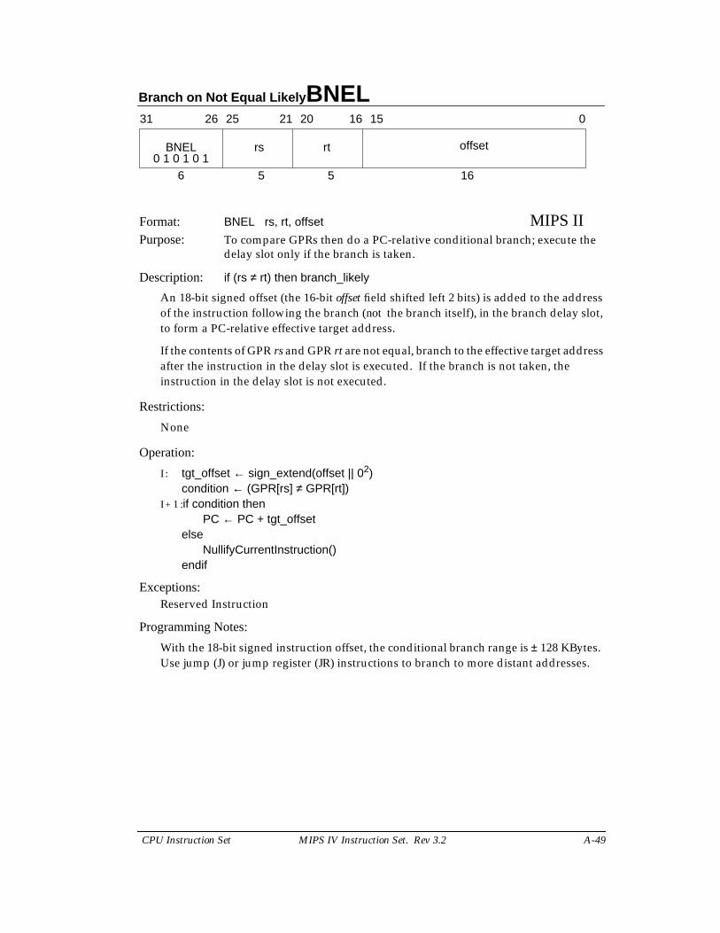
Branch on Not Equal Likely BNEL
CPU Instruction Set MIPS IV Instruction Set. Rev 3.2 A-49
Format: BNEL rs, rt, offset MIPS IIPurpose: To compare GPRs then do a PC-relative conditional branch; execute the
delay slot only if the branch is taken.
Description: if (rs ≠ rt) then branch_likely
An 18-bit signed offset (the 16-bit offset field shifted left 2 bits) is added to the addressof the instruction following the branch (not the branch itself), in the branch delay slot,to form a PC-relative effective target address.
If the contents of GPR rs and GPR rt are not equal, branch to the effective target addressafter the instruction in the delay slot is executed. If the branch is not taken, theinstruction in the delay slot is not executed.
Restrictions:
None
Operation:
I : tgt_offset ← sign_extend(offset || 02)condition ← (GPR[rs] ≠ GPR[rt])
I + 1 :if condition thenPC ← PC + tgt_offset
elseNullifyCurrentInstruction()
endif
Exceptions:Reserved Instruction
Programming Notes:
With the 18-bit signed instruction offset, the conditional branch range is ± 128 KBytes.Use jump (J) or jump register (JR) instructions to branch to more distant addresses.
31 2526 2021 1516 0
BNEL rs rt offset
6 5 5 160 1 0 1 0 1
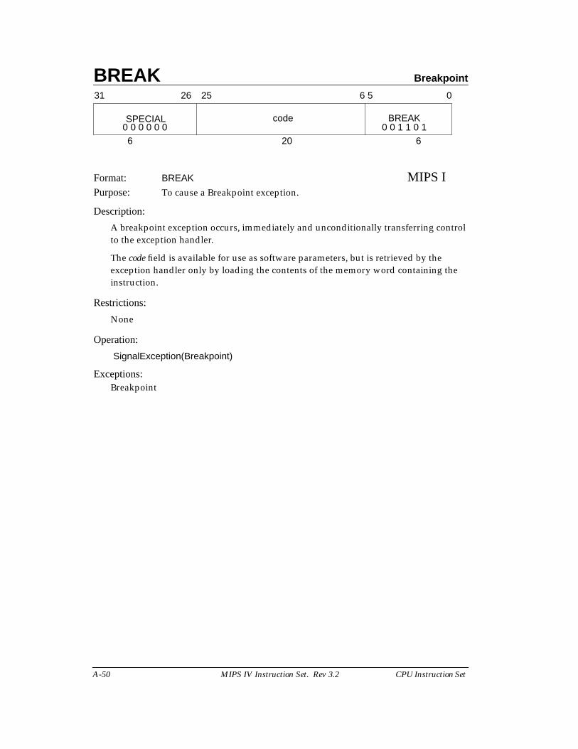
BREAK Breakpoint
A-50 MIPS IV Instruction Set. Rev 3.2 CPU Instruction Set
Format: BREAK MIPS IPurpose: To cause a Breakpoint exception.
Description:
A breakpoint exception occurs, immediately and unconditionally transferring controlto the exception handler.
The code field is available for use as software parameters, but is retrieved by theexception handler only by loading the contents of the memory word containing theinstruction.
Restrictions:
None
Operation:
SignalException(Breakpoint)
Exceptions:Breakpoint
31 2526
SPECIAL
6
0
BREAKcode
6 5
6200 0 0 0 0 0 0 0 1 1 0 1
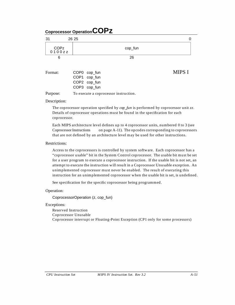
Coprocessor Operation COPz
CPU Instruction Set MIPS IV Instruction Set. Rev 3.2 A-51
Format: COP0 cop_fun MIPS ICOP1 cop_funCOP2 cop_funCOP3 cop_fun
Purpose: To execute a coprocessor instruction.
Description:
The coprocessor operation specified by cop_fun is performed by coprocessor unit zz.Details of coprocessor operations must be found in the specification for eachcoprocessor.
Each MIPS architecture level defines up to 4 coprocessor units, numbered 0 to 3 (seeCoprocessor Instructions on page A-11). The opcodes corresponding to coprocessorsthat are not defined by an architecture level may be used for other instructions.
Restrictions:
Access to the coprocessors is controlled by system software. Each coprocessor has a“coprocessor usable” bit in the System Control coprocessor. The usable bit must be setfor a user program to execute a coprocessor instruction. If the usable bit is not set, anattempt to execute the instruction will result in a Coprocessor Unusable exception. Anunimplemented coprocessor must never be enabled. The result of executing thisinstruction for an unimplemented coprocessor when the usable bit is set, is undefined.
See specification for the specific coprocessor being programmed.
Operation:
CoprocessorOperation (z, cop_fun)
Exceptions:Reserved InstructionCoprocessor UnusableCoprocessor interrupt or Floating-Point Exception (CP1 only for some processors)
31 2526
COPz
6
0
cop_fun
260 1 0 0 z z
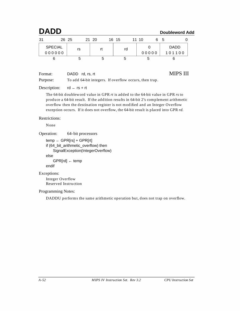
DADD Doubleword Add
A-52 MIPS IV Instruction Set. Rev 3.2 CPU Instruction Set
Format: DADD rd, rs, rt MIPS IIIPurpose: To add 64-bit integers. If overflow occurs, then trap.
Description: rd ← rs + rt
The 64-bit doubleword value in GPR rt is added to the 64-bit value in GPR rs toproduce a 64-bit result. If the addition results in 64-bit 2’s complement arithmeticoverflow then the destination register is not modified and an Integer Overflowexception occurs. If it does not overflow, the 64-bit result is placed into GPR rd.
Restrictions:
None
Operation: 64-bit processors
temp ← GPR[rs] + GPR[rt]if (64_bit_arithmetic_overflow) then
SignalException(IntegerOverflow)else
GPR[rd] ← tempendif
Exceptions:Integer OverflowReserved Instruction
Programming Notes:
DADDU performs the same arithmetic operation but, does not trap on overflow.
31 2526 2021 1516
SPECIAL rs rt
6 5 5
rd 0 DADD
5 5 6
11 10 6 5 0
0 0 0 0 0 0 0 0 0 0 0 1 0 1 1 0 0
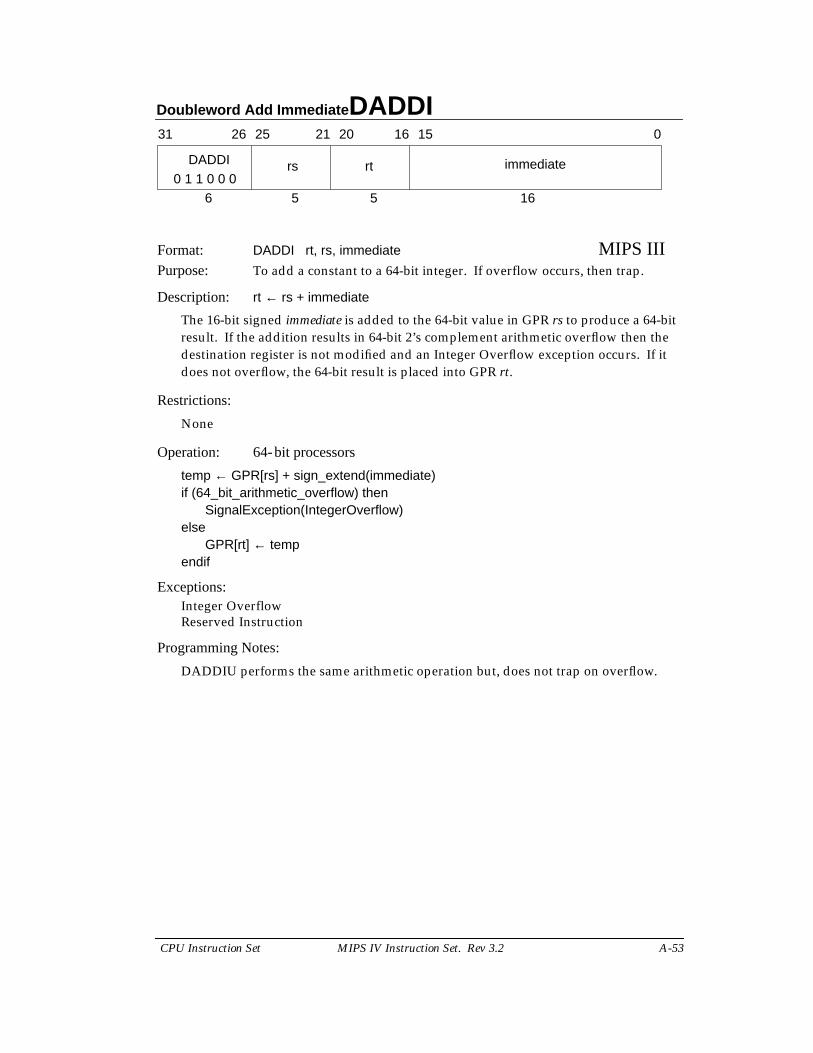
Doubleword Add Immediate DADDI
CPU Instruction Set MIPS IV Instruction Set. Rev 3.2 A-53
Format: DADDI rt, rs, immediate MIPS IIIPurpose: To add a constant to a 64-bit integer. If overflow occurs, then trap.
Description: rt ← rs + immediate
The 16-bit signed immediate is added to the 64-bit value in GPR rs to produce a 64-bitresult. If the addition results in 64-bit 2’s complement arithmetic overflow then thedestination register is not modified and an Integer Overflow exception occurs. If itdoes not overflow, the 64-bit result is placed into GPR rt.
Restrictions:
None
Operation: 64-bit processors
temp ← GPR[rs] + sign_extend(immediate)if (64_bit_arithmetic_overflow) then
SignalException(IntegerOverflow)else
GPR[rt] ← tempendif
Exceptions:Integer OverflowReserved Instruction
Programming Notes:
DADDIU performs the same arithmetic operation but, does not trap on overflow.
31 2526 2021 1516 0
DADDI rs rt immediate
6 5 5 160 1 1 0 0 0
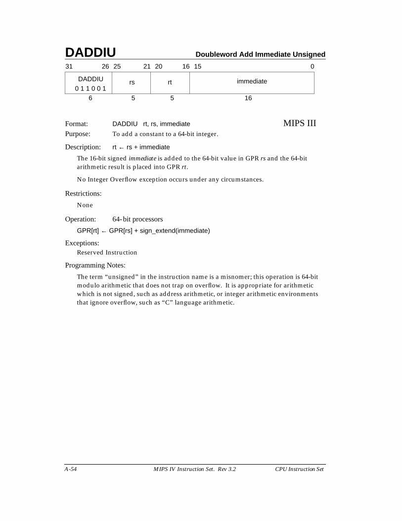
DADDIU Doubleword Add Immediate Unsigned
A-54 MIPS IV Instruction Set. Rev 3.2 CPU Instruction Set
Format: DADDIU rt, rs, immediate MIPS IIIPurpose: To add a constant to a 64-bit integer.
Description: rt ← rs + immediate
The 16-bit signed immediate is added to the 64-bit value in GPR rs and the 64-bitarithmetic result is placed into GPR rt.
No Integer Overflow exception occurs under any circumstances.
Restrictions:
None
Operation: 64-bit processors
GPR[rt] ← GPR[rs] + sign_extend(immediate)
Exceptions:Reserved Instruction
Programming Notes:
The term “unsigned” in the instruction name is a misnomer; this operation is 64-bitmodulo arithmetic that does not trap on overflow. It is appropriate for arithmeticwhich is not signed, such as address arithmetic, or integer arithmetic environmentsthat ignore overflow, such as “C” language arithmetic.
31 2526 2021 1516 0
DADDIU rs rt immediate
6 5 5 160 1 1 0 0 1
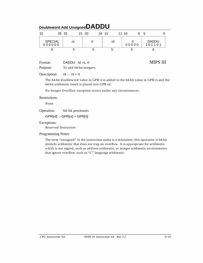
Doubleword Add Unsigned DADDU
CPU Instruction Set MIPS IV Instruction Set. Rev 3.2 A-55
Format: DADDU rd, rs, rt MIPS IIIPurpose: To add 64-bit integers.
Description: rd ← rs + rt
The 64-bit doubleword value in GPR rt is added to the 64-bit value in GPR rs and the64-bit arithmetic result is placed into GPR rd.
No Integer Overflow exception occurs under any circumstances.
Restrictions:
None
Operation: 64-bit processors
GPR[rd] ←GPR[rs] + GPR[rt]
Exceptions:Reserved Instruction
Programming Notes:
The term “unsigned” in the instruction name is a misnomer; this operation is 64-bitmodulo arithmetic that does not trap on overflow. It is appropriate for arithmeticwhich is not signed, such as address arithmetic, or integer arithmetic environmentsthat ignore overflow, such as “C” language arithmetic.
31 2526 2021 1516
SPECIAL rs rt
6 5 5
rd 0 DADDU
5 5 6
11 10 6 5 0
0 0 0 0 0 0 0 0 0 0 0 1 0 1 1 0 1
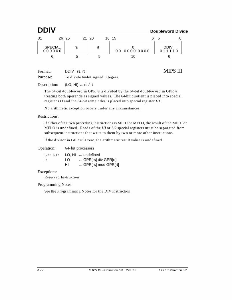
DDIV Doubleword Divide
A-56 MIPS IV Instruction Set. Rev 3.2 CPU Instruction Set
Format: DDIV rs, rt MIPS IIIPurpose: To divide 64-bit signed integers.
Description: (LO, HI) ← rs / rt
The 64-bit doubleword in GPR rs is divided by the 64-bit doubleword in GPR rt,treating both operands as signed values. The 64-bit quotient is placed into specialregister LO and the 64-bit remainder is placed into special register HI.
No arithmetic exception occurs under any circumstances.
Restrictions:
If either of the two preceding instructions is MFHI or MFLO, the result of the MFHI orMFLO is undefined. Reads of the HI or LO special registers must be separated fromsubsequent instructions that write to them by two or more other instructions.
If the divisor in GPR rt is zero, the arithmetic result value is undefined.
Operation: 64-bit processors
I - 2 :, I - 1 : LO, HI ← undefinedI : LO ← GPR[rs] div GPR[rt]
HI ← GPR[rs] mod GPR[rt]
Exceptions:Reserved Instruction
Programming Notes:
See the Programming Notes for the DIV instruction.
31 2526 2021 1516 0
rs rt
6 5 5
6 5
10 6
SPECIAL 0 DDIV0 0 0 0 0 0 0 0 0 0 0 0 0 0 0 0 0 1 1 1 1 0
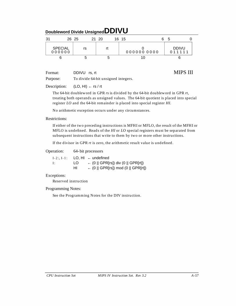
Doubleword Divide Unsigned DDIVU
CPU Instruction Set MIPS IV Instruction Set. Rev 3.2 A-57
Format: DDIVU rs, rt MIPS IIIPurpose: To divide 64-bit unsigned integers.
Description: (LO, HI) ← rs / rt
The 64-bit doubleword in GPR rs is divided by the 64-bit doubleword in GPR rt,treating both operands as unsigned values. The 64-bit quotient is placed into specialregister LO and the 64-bit remainder is placed into special register HI.
No arithmetic exception occurs under any circumstances.
Restrictions:
If either of the two preceding instructions is MFHI or MFLO, the result of the MFHI orMFLO is undefined. Reads of the HI or LO special registers must be separated fromsubsequent instructions that write to them by two or more other instructions.
If the divisor in GPR rt is zero, the arithmetic result value is undefined.
Operation: 64-bit processors
I - 2 :, I - 1 : LO, HI ← undefinedI : LO ← (0 || GPR[rs]) div (0 || GPR[rt])
HI ← (0 || GPR[rs]) mod (0 || GPR[rt])
Exceptions:Reserved instruction
Programming Notes:
See the Programming Notes for the DIV instruction.
31 2526 2021 1516 0
rs rt
6 5 5
6 5
10 6
SPECIAL 0 DDIVU0 0 0 0 0 0 0 0 0 0 0 0 0 0 0 0 0 1 1 1 1 1
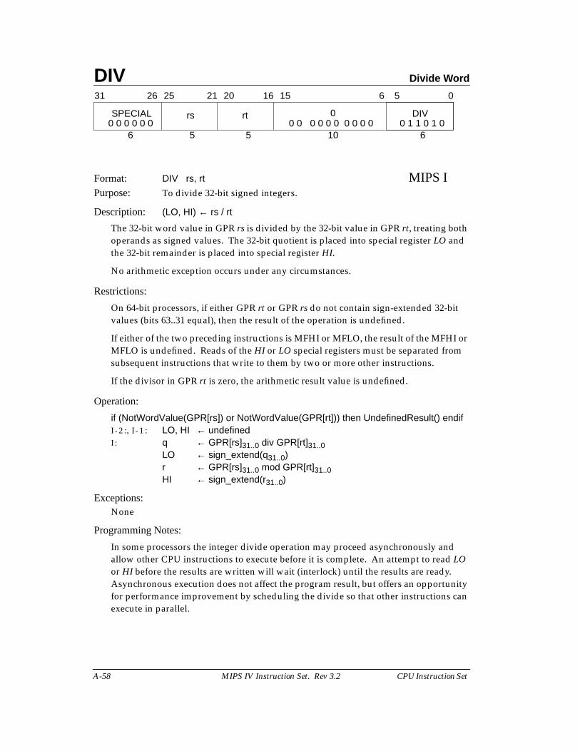
DIV Divide Word
A-58 MIPS IV Instruction Set. Rev 3.2 CPU Instruction Set
Format: DIV rs, rt MIPS IPurpose: To divide 32-bit signed integers.
Description: (LO, HI) ← rs / rt
The 32-bit word value in GPR rs is divided by the 32-bit value in GPR rt, treating bothoperands as signed values. The 32-bit quotient is placed into special register LO andthe 32-bit remainder is placed into special register HI.
No arithmetic exception occurs under any circumstances.
Restrictions:
On 64-bit processors, if either GPR rt or GPR rs do not contain sign-extended 32-bitvalues (bits 63..31 equal), then the result of the operation is undefined.
If either of the two preceding instructions is MFHI or MFLO, the result of the MFHI orMFLO is undefined. Reads of the HI or LO special registers must be separated fromsubsequent instructions that write to them by two or more other instructions.
If the divisor in GPR rt is zero, the arithmetic result value is undefined.
Operation:
if (NotWordValue(GPR[rs]) or NotWordValue(GPR[rt])) then UndefinedResult() endifI - 2 :, I - 1 : LO, HI ← undefinedI : q ← GPR[rs]31..0 div GPR[rt]31..0
LO ← sign_extend(q31..0)r ← GPR[rs]31..0 mod GPR[rt]31..0HI ← sign_extend(r31..0)
Exceptions:None
Programming Notes:
In some processors the integer divide operation may proceed asynchronously andallow other CPU instructions to execute before it is complete. An attempt to read LOor HI before the results are written will wait (interlock) until the results are ready.Asynchronous execution does not affect the program result, but offers an opportunityfor performance improvement by scheduling the divide so that other instructions canexecute in parallel.
31 2526 2021 1516 0
rs rt
6 5 5
6 5
10 6
SPECIAL 0 DIV0 0 0 0 0 0 0 0 0 0 0 0 0 0 0 0 0 1 1 0 1 0
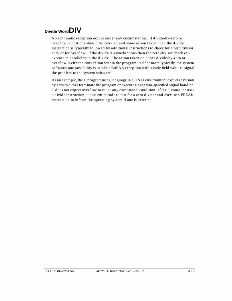
Divide Word DIV
CPU Instruction Set MIPS IV Instruction Set. Rev 3.2 A-59
No arithmetic exception occurs under any circumstances. If divide-by-zero oroverflow conditions should be detected and some action taken, then the divideinstruction is typically followed by additional instructions to check for a zero divisorand/or for overflow. If the divide is asynchronous then the zero-divisor check canexecute in parallel with the divide. The action taken on either divide-by-zero oroverflow is either a convention within the program itself or more typically, the systemsoftware; one possibility is to take a BREAK exception with a code field value to signalthe problem to the system software.
As an example, the C programming language in a UNIX environment expects divisionby zero to either terminate the program or execute a program-specified signal handler.C does not expect overflow to cause any exceptional condition. If the C compiler usesa divide instruction, it also emits code to test for a zero divisor and execute a BREAKinstruction to inform the operating system if one is detected.
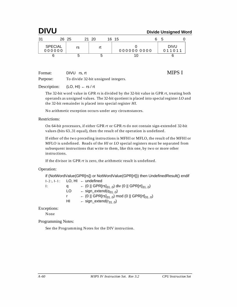
DIVU Divide Unsigned Word
A-60 MIPS IV Instruction Set. Rev 3.2 CPU Instruction Set
Format: DIVU rs, rt MIPS IPurpose: To divide 32-bit unsigned integers.
Description: (LO, HI) ← rs / rt
The 32-bit word value in GPR rs is divided by the 32-bit value in GPR rt, treating bothoperands as unsigned values. The 32-bit quotient is placed into special register LO andthe 32-bit remainder is placed into special register HI.
No arithmetic exception occurs under any circumstances.
Restrictions:
On 64-bit processors, if either GPR rt or GPR rs do not contain sign-extended 32-bitvalues (bits 63..31 equal), then the result of the operation is undefined.
If either of the two preceding instructions is MFHI or MFLO, the result of the MFHI orMFLO is undefined. Reads of the HI or LO special registers must be separated fromsubsequent instructions that write to them, like this one, by two or more otherinstructions.
If the divisor in GPR rt is zero, the arithmetic result is undefined.
Operation:
if (NotWordValue(GPR[rs]) or NotWordValue(GPR[rt])) then UndefinedResult() endifI - 2 :, I - 1 : LO, HI ← undefinedI : q ← (0 || GPR[rs]31..0) div (0 || GPR[rt]31..0)
LO ← sign_extend(q31..0)r ← (0 || GPR[rs]31..0) mod (0 || GPR[rt]31..0)HI ← sign_extend(r31..0)
Exceptions:None
Programming Notes:
See the Programming Notes for the DIV instruction.
31 2526 2021 1516 0
rs rt
6 5 5
6 5
10 6
SPECIAL 0 DIVU0 0 0 0 0 0 0 0 0 0 0 0 0 0 0 0 0 1 1 0 1 1
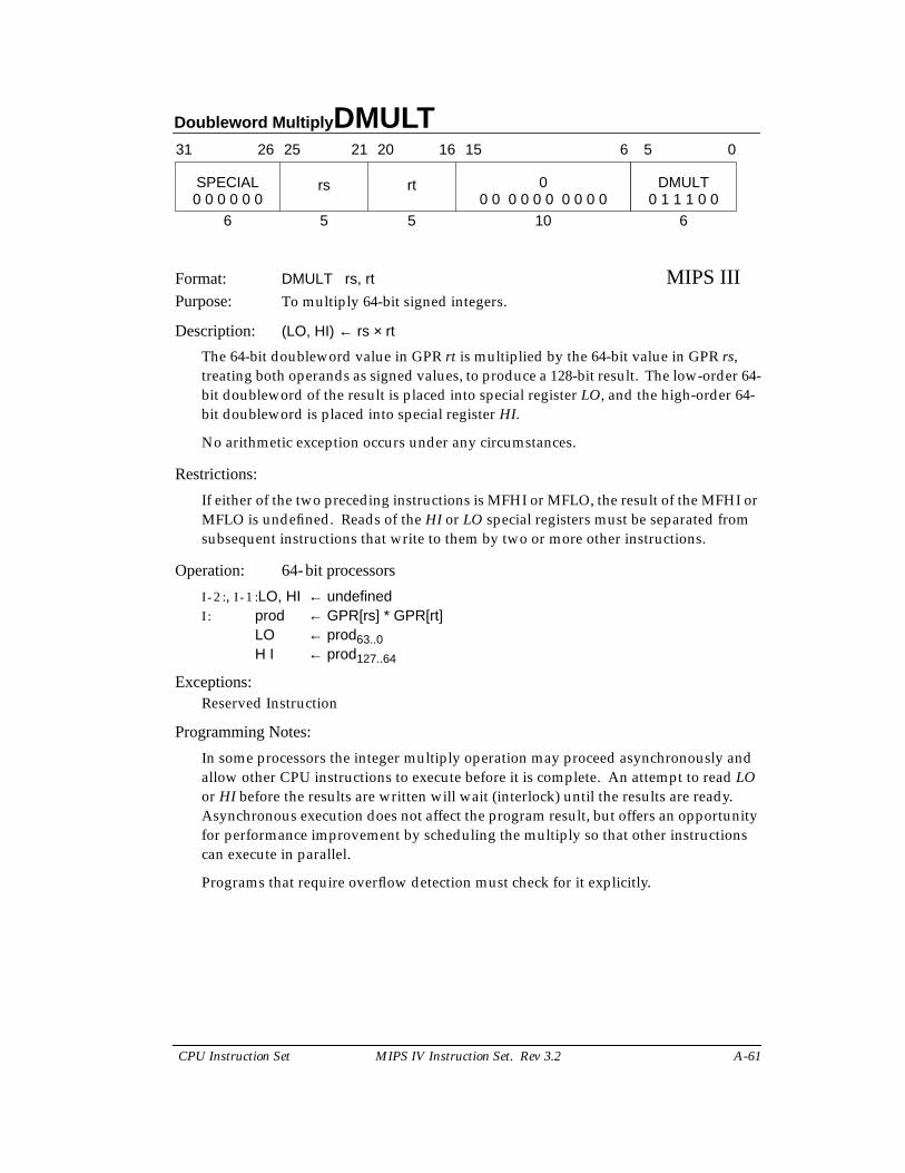
Doubleword Multiply DMULT
CPU Instruction Set MIPS IV Instruction Set. Rev 3.2 A-61
Format: DMULT rs, rt MIPS IIIPurpose: To multiply 64-bit signed integers.
Description: (LO, HI) ← rs × rt
The 64-bit doubleword value in GPR rt is multiplied by the 64-bit value in GPR rs,treating both operands as signed values, to produce a 128-bit result. The low-order 64-bit doubleword of the result is placed into special register LO, and the high-order 64-bit doubleword is placed into special register HI.
No arithmetic exception occurs under any circumstances.
Restrictions:
If either of the two preceding instructions is MFHI or MFLO, the result of the MFHI orMFLO is undefined. Reads of the HI or LO special registers must be separated fromsubsequent instructions that write to them by two or more other instructions.
Operation: 64-bit processors
I - 2 :, I - 1 :LO, HI ← undefinedI : prod ← GPR[rs] * GPR[rt]
LO ← prod63..0H I ← prod127..64
Exceptions:Reserved Instruction
Programming Notes:
In some processors the integer multiply operation may proceed asynchronously andallow other CPU instructions to execute before it is complete. An attempt to read LOor HI before the results are written will wait (interlock) until the results are ready.Asynchronous execution does not affect the program result, but offers an opportunityfor performance improvement by scheduling the multiply so that other instructionscan execute in parallel.
Programs that require overflow detection must check for it explicitly.
31 2526 2021 1516 0
rs rt
6 5 5
6 5
10 6
SPECIAL 0 DMULT0 0 0 0 0 0 0 0 0 0 0 0 0 0 0 0 0 1 1 1 0 0
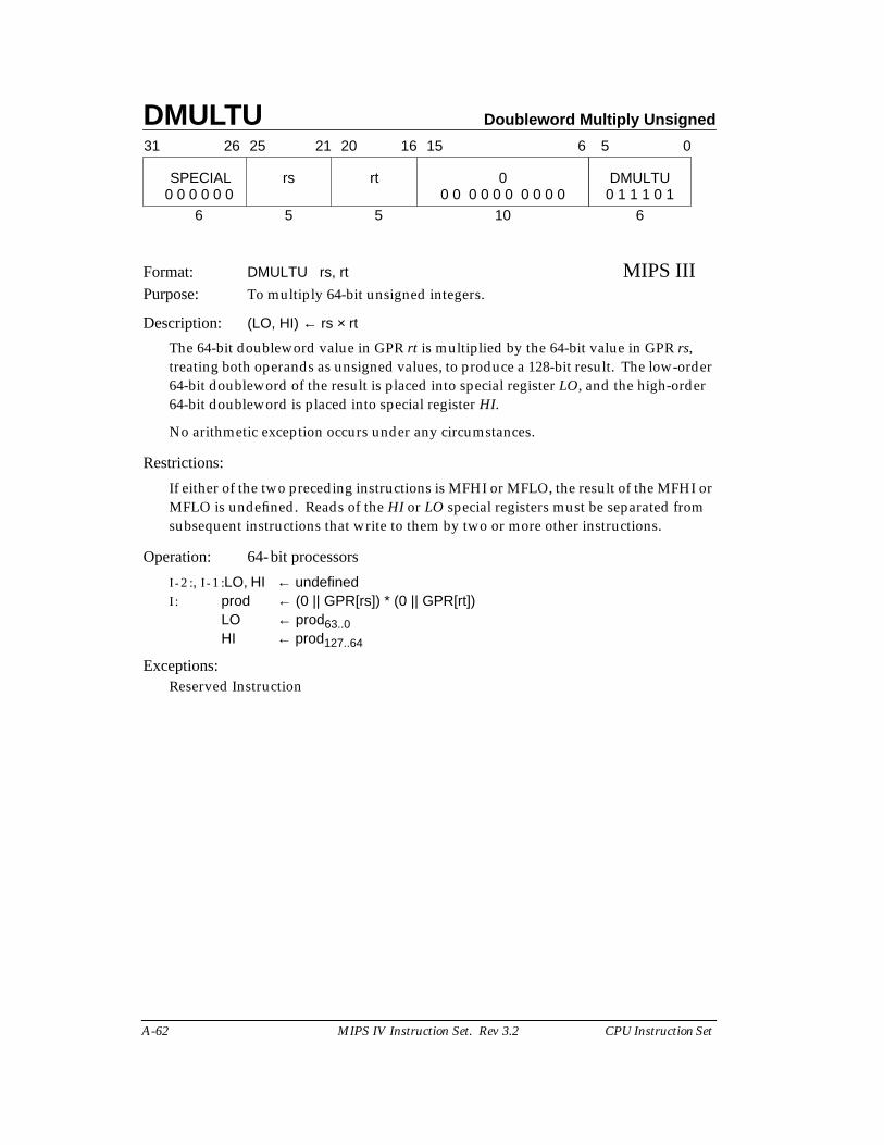
DMULTU Doubleword Multiply Unsigned
A-62 MIPS IV Instruction Set. Rev 3.2 CPU Instruction Set
Format: DMULTU rs, rt MIPS IIIPurpose: To multiply 64-bit unsigned integers.
Description: (LO, HI) ← rs × rt
The 64-bit doubleword value in GPR rt is multiplied by the 64-bit value in GPR rs,treating both operands as unsigned values, to produce a 128-bit result. The low-order64-bit doubleword of the result is placed into special register LO, and the high-order64-bit doubleword is placed into special register HI.
No arithmetic exception occurs under any circumstances.
Restrictions:
If either of the two preceding instructions is MFHI or MFLO, the result of the MFHI orMFLO is undefined. Reads of the HI or LO special registers must be separated fromsubsequent instructions that write to them by two or more other instructions.
Operation: 64-bit processors
I - 2 :, I - 1 :LO, HI ← undefinedI : prod ← (0 || GPR[rs]) * (0 || GPR[rt])
LO ← prod63..0HI ← prod127..64
Exceptions:Reserved Instruction
31 2526 2021 1516 0
rs rt
6 5 5
6 5
10 6
SPECIAL 0 DMULTU0 0 0 0 0 0 0 0 0 0 0 0 0 0 0 0 0 1 1 1 0 1
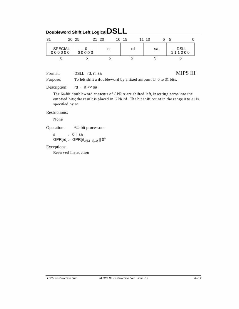
Doubleword Shift Left Logical DSLL
CPU Instruction Set MIPS IV Instruction Set. Rev 3.2 A-63
Format: DSLL rd, rt, sa MIPS IIIPurpose: To left shift a doubleword by a fixed amount 0 to 31 bits.
Description: rd ← rt << sa
The 64-bit doubleword contents of GPR rt are shifted left, inserting zeros into theemptied bits; the result is placed in GPR rd. The bit shift count in the range 0 to 31 isspecified by sa.
Restrictions:
None
Operation: 64-bit processors
s ← 0 || saGPR[rd]← GPR[rt](63–s)..0 || 0s
Exceptions:Reserved Instruction
31 2526 2021 1516
SPECIAL 0 rt
6 5 5
rd sa DSLL
5 5 6
11 10 6 5 0
0 0 0 0 0 0 1 1 1 0 0 00 0 0 0 0
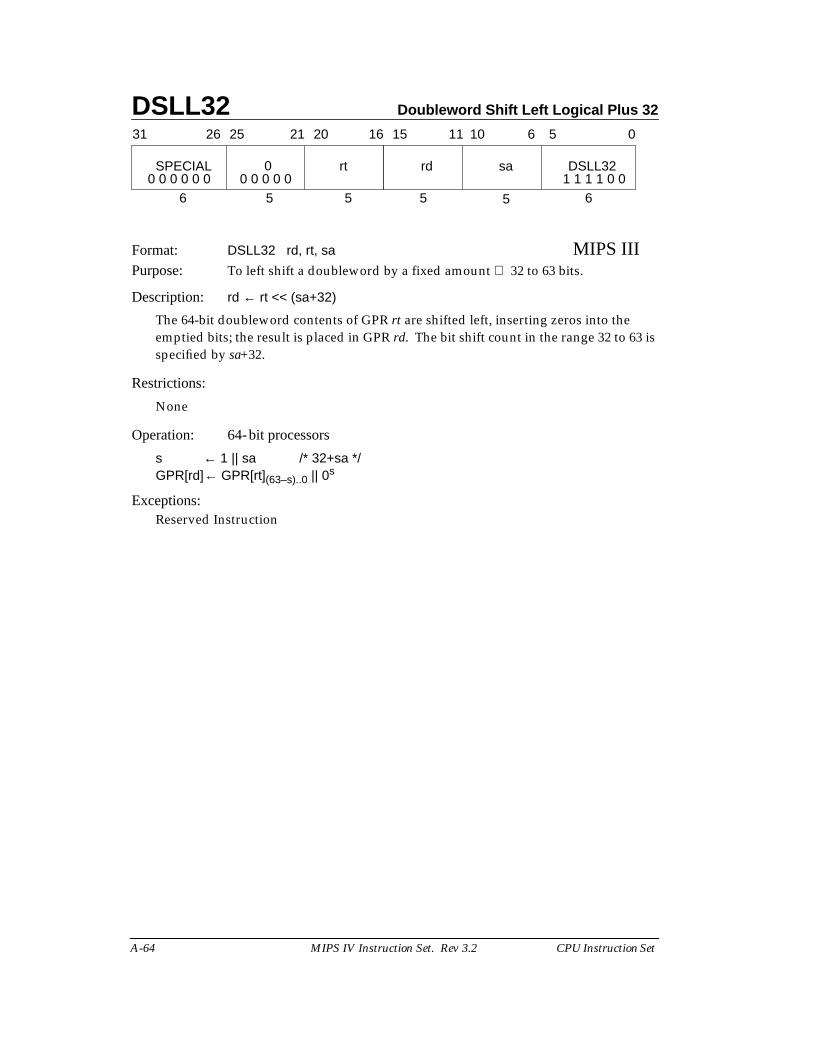
DSLL32 Doubleword Shift Left Logical Plus 32
A-64 MIPS IV Instruction Set. Rev 3.2 CPU Instruction Set
Format: DSLL32 rd, rt, sa MIPS IIIPurpose: To left shift a doubleword by a fixed amount 32 to 63 bits.
Description: rd ← rt << (sa+32)
The 64-bit doubleword contents of GPR rt are shifted left, inserting zeros into theemptied bits; the result is placed in GPR rd. The bit shift count in the range 32 to 63 isspecified by sa+32.
Restrictions:
None
Operation: 64-bit processors
s ← 1 || sa /* 32+sa */GPR[rd]← GPR[rt](63–s)..0 || 0s
Exceptions:Reserved Instruction
31 2526 2021 1516
SPECIAL rt
6 5 5
rd sa DSLL32
5 5 6
11 10 6 5 0
0 0 0 0 0 0 1 1 1 1 0 00
0 0 0 0 0
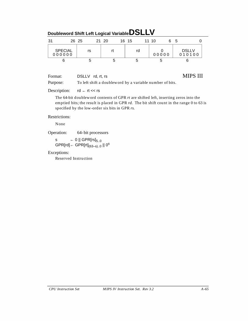
Doubleword Shift Left Logical Variable DSLLV
CPU Instruction Set MIPS IV Instruction Set. Rev 3.2 A-65
Format: DSLLV rd, rt, rs MIPS IIIPurpose: To left shift a doubleword by a variable number of bits.
Description: rd ← rt << rs
The 64-bit doubleword contents of GPR rt are shifted left, inserting zeros into theemptied bits; the result is placed in GPR rd. The bit shift count in the range 0 to 63 isspecified by the low-order six bits in GPR rs.
Restrictions:
None
Operation: 64-bit processors
s ← 0 || GPR[rs]5..0GPR[rd]← GPR[rt](63–s)..0 || 0s
Exceptions:Reserved Instruction
31 2526 2021 1516
SPECIAL rs rt
6 5 5
rd 0 DSLLV
5 5 6
11 10 6 5 0
0 0 0 0 0 0 0 1 0 1 0 00 0 0 0 0
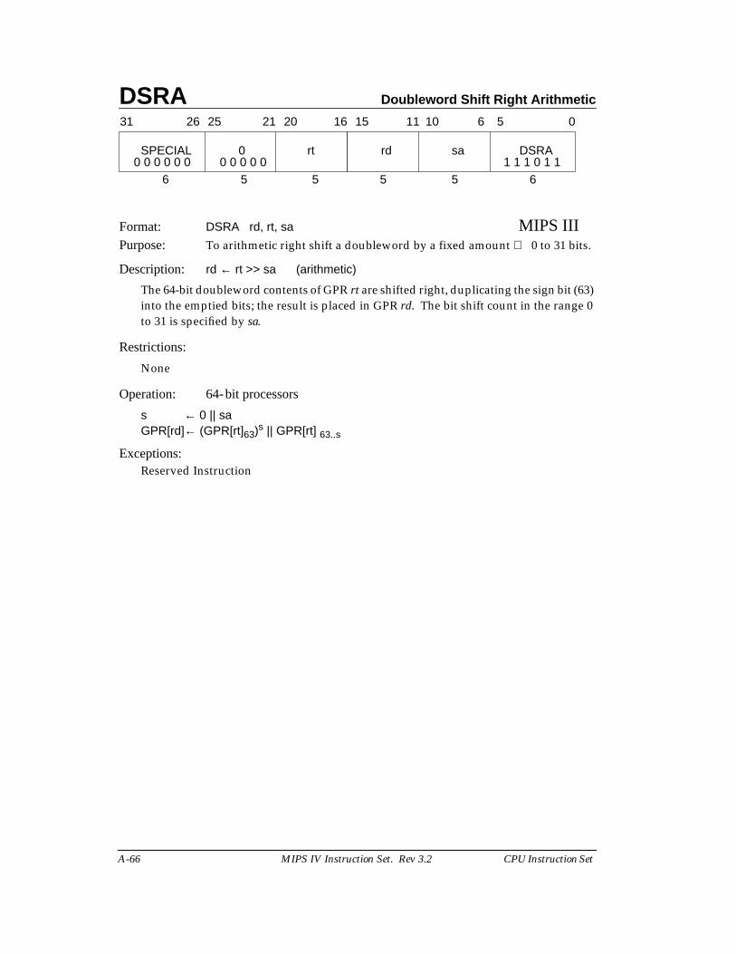
DSRA Doubleword Shift Right Arithmetic
A-66 MIPS IV Instruction Set. Rev 3.2 CPU Instruction Set
Format: DSRA rd, rt, sa MIPS IIIPurpose: To arithmetic right shift a doubleword by a fixed amount 0 to 31 bits.
Description: rd ← rt >> sa (arithmetic)
The 64-bit doubleword contents of GPR rt are shifted right, duplicating the sign bit (63)into the emptied bits; the result is placed in GPR rd. The bit shift count in the range 0to 31 is specified by sa.
Restrictions:
None
Operation: 64-bit processors
s ← 0 || saGPR[rd]← (GPR[rt]63)s || GPR[rt] 63..s
Exceptions:Reserved Instruction
31 2526 2021 1516
SPECIAL 0 rt
6 5 5
rd sa DSRA
5 5 6
11 10 6 5 0
0 0 0 0 0 0 0 0 0 0 0 1 1 1 0 1 1
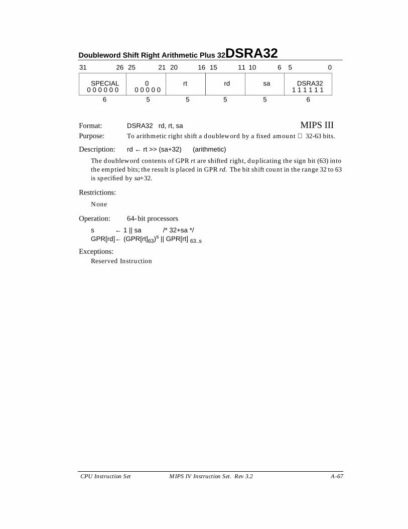
Doubleword Shift Right Arithmetic Plus 32 DSRA32
CPU Instruction Set MIPS IV Instruction Set. Rev 3.2 A-67
Format: DSRA32 rd, rt, sa MIPS IIIPurpose: To arithmetic right shift a doubleword by a fixed amount 32-63 bits.
Description: rd ← rt >> (sa+32) (arithmetic)
The doubleword contents of GPR rt are shifted right, duplicating the sign bit (63) intothe emptied bits; the result is placed in GPR rd. The bit shift count in the range 32 to 63is specified by sa+32.
Restrictions:
None
Operation: 64-bit processors
s ← 1 || sa /* 32+sa */GPR[rd]← (GPR[rt]63)s || GPR[rt] 63..s
Exceptions:Reserved Instruction
31 2526 2021 1516
SPECIAL 0 rt
6 5 5
rd sa DSRA32
5 5 6
11 10 6 5 0
0 0 0 0 0 0 0 0 0 0 0 1 1 1 1 1 1
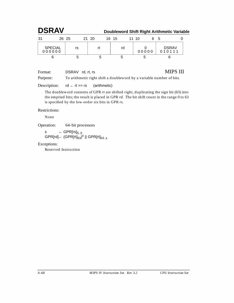
DSRAV Doubleword Shift Right Arithmetic Variable
A-68 MIPS IV Instruction Set. Rev 3.2 CPU Instruction Set
Format: DSRAV rd, rt, rs MIPS IIIPurpose: To arithmetic right shift a doubleword by a variable number of bits.
Description: rd ← rt >> rs (arithmetic)
The doubleword contents of GPR rt are shifted right, duplicating the sign bit (63) intothe emptied bits; the result is placed in GPR rd. The bit shift count in the range 0 to 63is specified by the low-order six bits in GPR rs.
Restrictions:
None
Operation: 64-bit processors
s ← GPR[rs]5..0GPR[rd]← (GPR[rt]63)s || GPR[rt]63..s
Exceptions:Reserved Instruction
31 2526 2021 1516
SPECIAL rs rt
6 5 5
rd 0 DSRAV
5 5 6
11 10 6 5 0
0 0 0 0 0 0 0 0 0 0 0 0 1 0 1 1 1
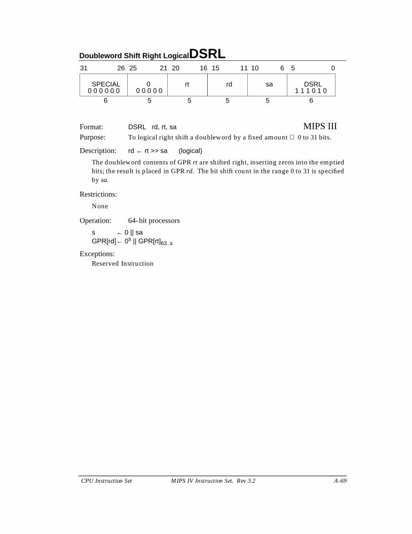
Doubleword Shift Right Logical DSRL
CPU Instruction Set MIPS IV Instruction Set. Rev 3.2 A-69
Format: DSRL rd, rt, sa MIPS IIIPurpose: To logical right shift a doubleword by a fixed amount 0 to 31 bits.
Description: rd ← rt >> sa (logical)
The doubleword contents of GPR rt are shifted right, inserting zeros into the emptiedbits; the result is placed in GPR rd. The bit shift count in the range 0 to 31 is specifiedby sa.
Restrictions:
None
Operation: 64-bit processors
s ← 0 || saGPR[rd]← 0s || GPR[rt]63..s
Exceptions:Reserved Instruction
31 2526 2021 1516
SPECIAL rt
6 5 5
rd sa DSRL
5 5 6
11 10 6 5 0
0 0 0 0 0 0 1 1 1 0 1 00
0 0 0 0 0

DSRL32 Doubleword Shift Right Logical Plus 32
A-70 MIPS IV Instruction Set. Rev 3.2 CPU Instruction Set
Format: DSRL32 rd, rt, sa MIPS IIIPurpose: To logical right shift a doubleword by a fixed amount 32 to 63 bits.
Description: rd ← rt >> (sa+32) (logical)
The 64-bit doubleword contents of GPR rt are shifted right, inserting zeros into theemptied bits; the result is placed in GPR rd. The bit shift count in the range 32 to 63 isspecified by sa+32.
Restrictions:
None
Operation: 64-bit processors
s ← 1 || sa /* 32+sa */GPR[rd]← 0s || GPR[rt]63..s
Exceptions:Reserved Instruction
31 2526 2021 1516
SPECIAL rt
6 5 5
rd sa DSRL32
5 5 6
11 10 6 5 0
0 0 0 0 0 0 1 1 1 1 1 00
0 0 0 0 0
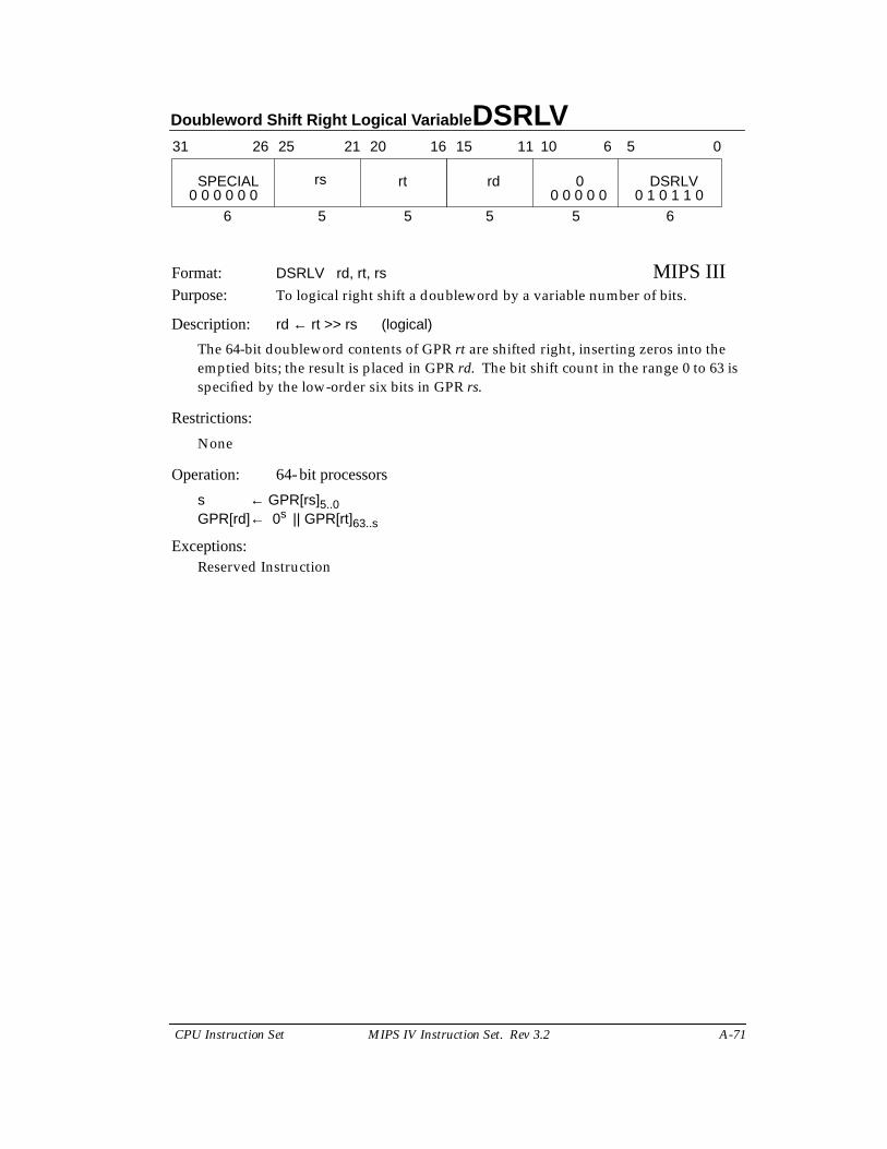
Doubleword Shift Right Logical Variable DSRLV
CPU Instruction Set MIPS IV Instruction Set. Rev 3.2 A-71
Format: DSRLV rd, rt, rs MIPS IIIPurpose: To logical right shift a doubleword by a variable number of bits.
Description: rd ← rt >> rs (logical)
The 64-bit doubleword contents of GPR rt are shifted right, inserting zeros into theemptied bits; the result is placed in GPR rd. The bit shift count in the range 0 to 63 isspecified by the low-order six bits in GPR rs.
Restrictions:
None
Operation: 64-bit processors
s ← GPR[rs]5..0GPR[rd]← 0s || GPR[rt]63..s
Exceptions:Reserved Instruction
31 2526 2021 1516
SPECIAL rt
6 5 5
rd 0 DSRLV
5 5 6
11 10 6 5 0
0 0 0 0 0 0 0 0 0 0 0 0 1 0 1 1 0rs
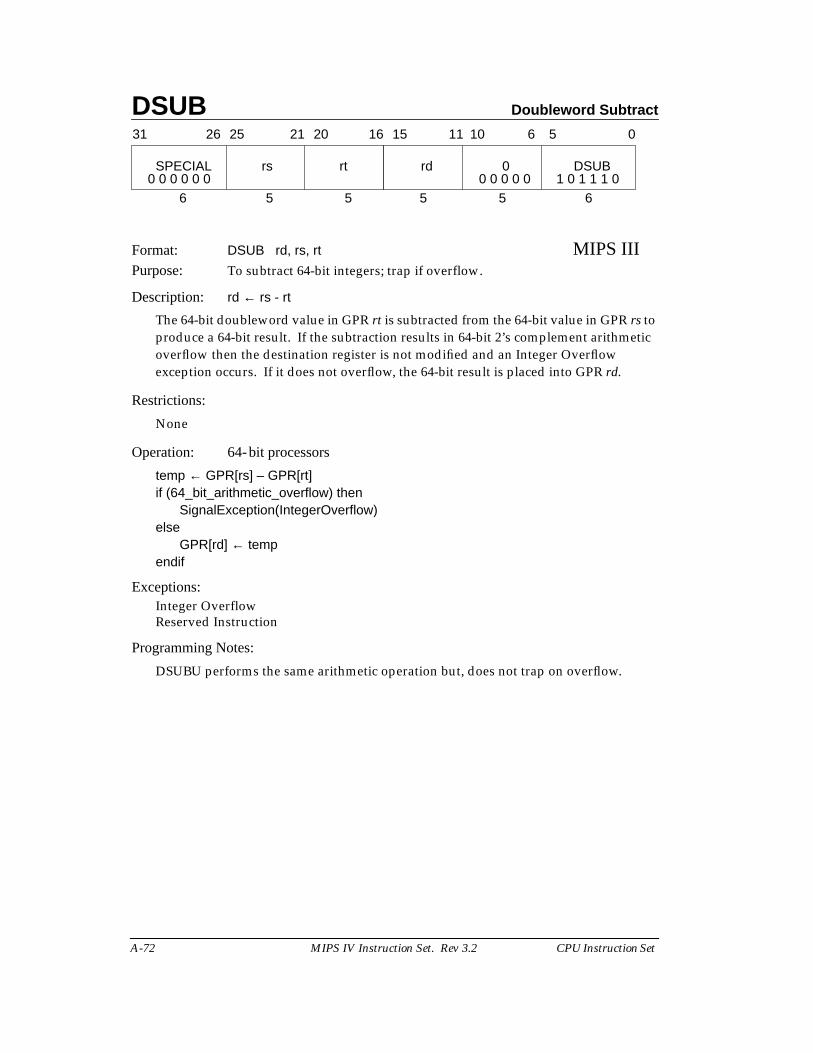
DSUB Doubleword Subtract
A-72 MIPS IV Instruction Set. Rev 3.2 CPU Instruction Set
Format: DSUB rd, rs, rt MIPS IIIPurpose: To subtract 64-bit integers; trap if overflow.
Description: rd ← rs - rt
The 64-bit doubleword value in GPR rt is subtracted from the 64-bit value in GPR rs toproduce a 64-bit result. If the subtraction results in 64-bit 2’s complement arithmeticoverflow then the destination register is not modified and an Integer Overflowexception occurs. If it does not overflow, the 64-bit result is placed into GPR rd.
Restrictions:
None
Operation: 64-bit processors
temp ← GPR[rs] – GPR[rt]if (64_bit_arithmetic_overflow) then
SignalException(IntegerOverflow)else
GPR[rd] ← tempendif
Exceptions:Integer OverflowReserved Instruction
Programming Notes:
DSUBU performs the same arithmetic operation but, does not trap on overflow.
31 2526 2021 1516
SPECIAL rs rt
6 5 5
rd 0 DSUB
5 5 6
11 10 6 5 0
0 0 0 0 0 0 0 0 0 0 0 1 0 1 1 1 0
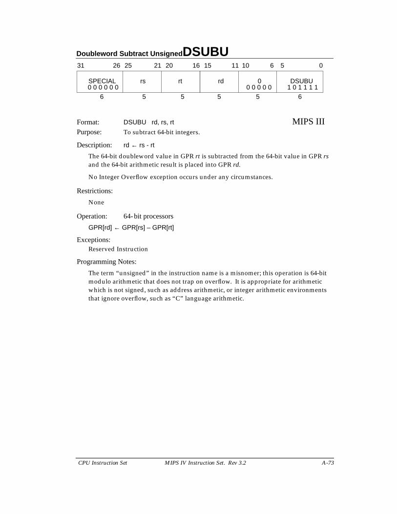
Doubleword Subtract Unsigned DSUBU
CPU Instruction Set MIPS IV Instruction Set. Rev 3.2 A-73
Format: DSUBU rd, rs, rt MIPS IIIPurpose: To subtract 64-bit integers.
Description: rd ← rs - rt
The 64-bit doubleword value in GPR rt is subtracted from the 64-bit value in GPR rsand the 64-bit arithmetic result is placed into GPR rd.
No Integer Overflow exception occurs under any circumstances.
Restrictions:
None
Operation: 64-bit processors
GPR[rd] ← GPR[rs] – GPR[rt]
Exceptions:Reserved Instruction
Programming Notes:
The term “unsigned” in the instruction name is a misnomer; this operation is 64-bitmodulo arithmetic that does not trap on overflow. It is appropriate for arithmeticwhich is not signed, such as address arithmetic, or integer arithmetic environmentsthat ignore overflow, such as “C” language arithmetic.
31 2526 2021 1516
SPECIAL rs rt
6 5 5
rd 0 DSUBU
5 5 6
11 10 6 5 0
0 0 0 0 0 0 0 0 0 0 0 1 0 1 1 1 1
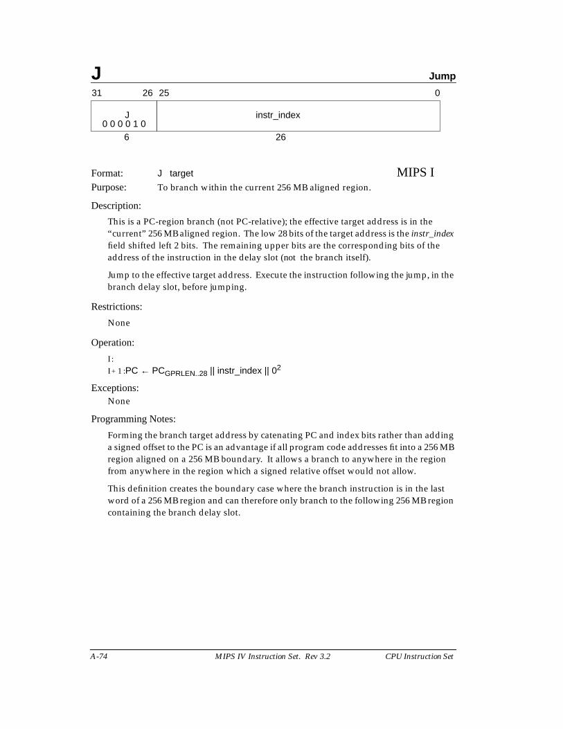
J Jump
A-74 MIPS IV Instruction Set. Rev 3.2 CPU Instruction Set
Format: J target MIPS IPurpose: To branch within the current 256 MB aligned region.
Description:
This is a PC-region branch (not PC-relative); the effective target address is in the“current” 256 MB aligned region. The low 28 bits of the target address is the instr_indexfield shifted left 2 bits. The remaining upper bits are the corresponding bits of theaddress of the instruction in the delay slot (not the branch itself).
Jump to the effective target address. Execute the instruction following the jump, in thebranch delay slot, before jumping.
Restrictions:
None
Operation:
I :I + 1 :PC ← PCGPRLEN..28 || instr_index || 02
Exceptions:None
Programming Notes:
Forming the branch target address by catenating PC and index bits rather than addinga signed offset to the PC is an advantage if all program code addresses fit into a 256 MBregion aligned on a 256 MB boundary. It allows a branch to anywhere in the regionfrom anywhere in the region which a signed relative offset would not allow.
This definition creates the boundary case where the branch instruction is in the lastword of a 256 MB region and can therefore only branch to the following 256 MB regioncontaining the branch delay slot.
31 2526
J
6
0
instr_index
260 0 0 0 1 0
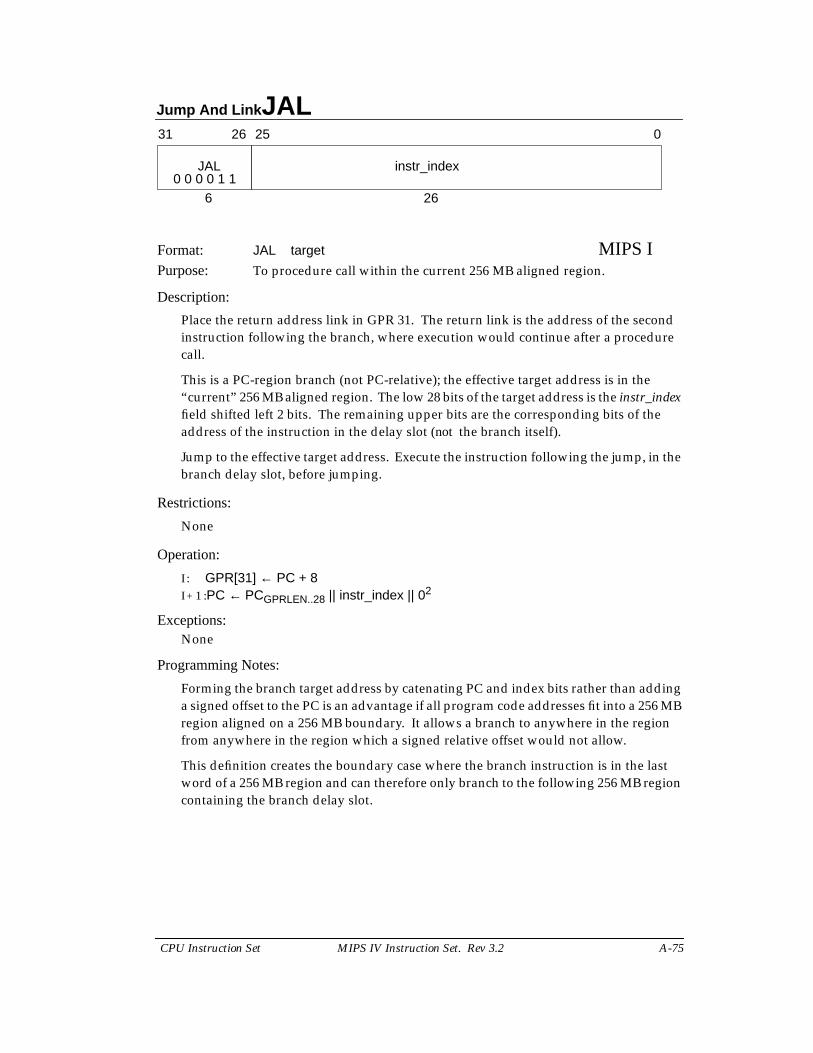
Jump And Link JAL
CPU Instruction Set MIPS IV Instruction Set. Rev 3.2 A-75
Format: JAL target MIPS IPurpose: To procedure call within the current 256 MB aligned region.
Description:
Place the return address link in GPR 31. The return link is the address of the secondinstruction following the branch, where execution would continue after a procedurecall.
This is a PC-region branch (not PC-relative); the effective target address is in the“current” 256 MB aligned region. The low 28 bits of the target address is the instr_indexfield shifted left 2 bits. The remaining upper bits are the corresponding bits of theaddress of the instruction in the delay slot (not the branch itself).
Jump to the effective target address. Execute the instruction following the jump, in thebranch delay slot, before jumping.
Restrictions:
None
Operation:
I : GPR[31] ← PC + 8I + 1 :PC ← PCGPRLEN..28 || instr_index || 02
Exceptions:None
Programming Notes:
Forming the branch target address by catenating PC and index bits rather than addinga signed offset to the PC is an advantage if all program code addresses fit into a 256 MBregion aligned on a 256 MB boundary. It allows a branch to anywhere in the regionfrom anywhere in the region which a signed relative offset would not allow.
This definition creates the boundary case where the branch instruction is in the lastword of a 256 MB region and can therefore only branch to the following 256 MB regioncontaining the branch delay slot.
31 2526
JAL
6
0
instr_index
260 0 0 0 1 1
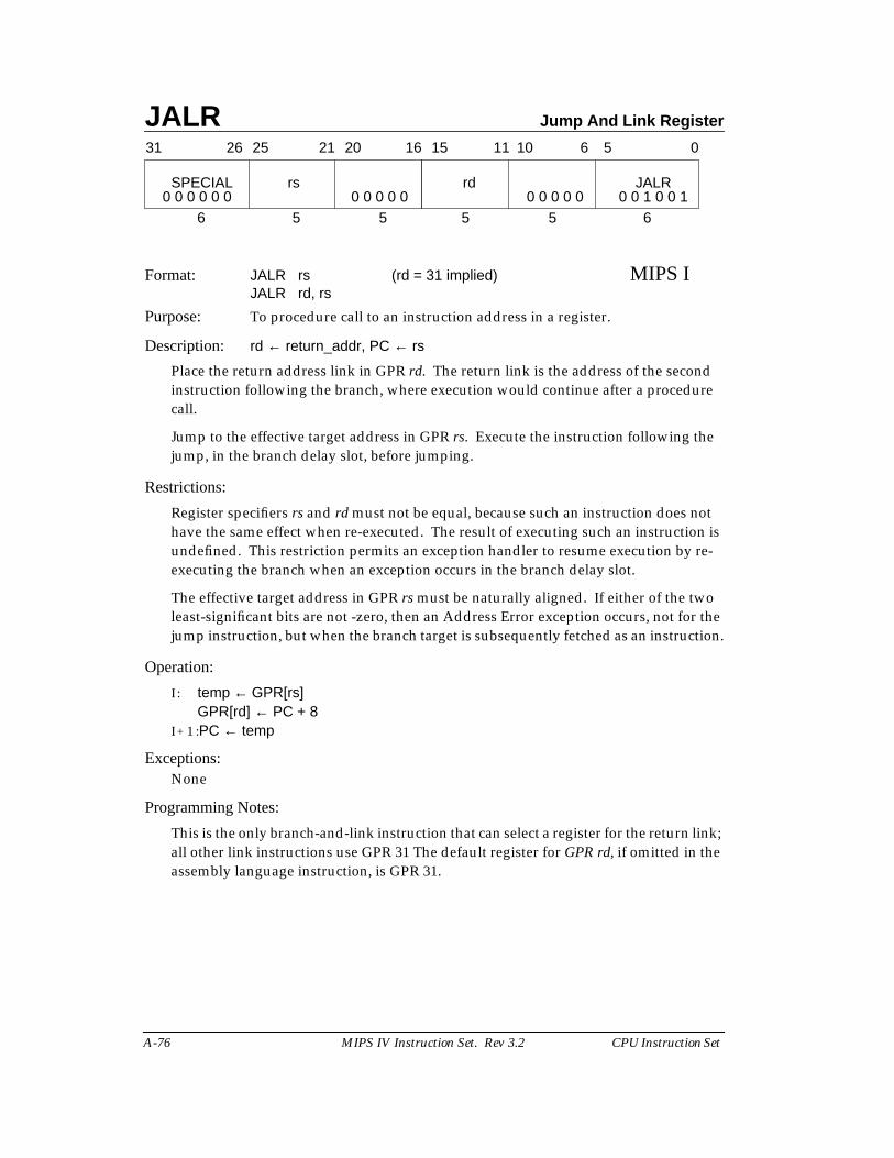
JALR Jump And Link Register
A-76 MIPS IV Instruction Set. Rev 3.2 CPU Instruction Set
Format: JALR rs (rd = 31 implied) MIPS IJALR rd, rs
Purpose: To procedure call to an instruction address in a register.
Description: rd ← return_addr, PC ← rs
Place the return address link in GPR rd. The return link is the address of the secondinstruction following the branch, where execution would continue after a procedurecall.
Jump to the effective target address in GPR rs. Execute the instruction following thejump, in the branch delay slot, before jumping.
Restrictions:
Register specifiers rs and rd must not be equal, because such an instruction does nothave the same effect when re-executed. The result of executing such an instruction isundefined. This restriction permits an exception handler to resume execution by re-executing the branch when an exception occurs in the branch delay slot.
The effective target address in GPR rs must be naturally aligned. If either of the twoleast-significant bits are not -zero, then an Address Error exception occurs, not for thejump instruction, but when the branch target is subsequently fetched as an instruction.
Operation:
I : temp ← GPR[rs]GPR[rd] ← PC + 8
I + 1 :PC ← temp
Exceptions:None
Programming Notes:
This is the only branch-and-link instruction that can select a register for the return link;all other link instructions use GPR 31 The default register for GPR rd, if omitted in theassembly language instruction, is GPR 31.
31 2526 2021 1516
SPECIAL rs
6 5 5
rd JALR
5 5 6
11 10 6 5 0
0 0 1 0 0 10 0 0 0 00 0 0 0 00 0 0 0 0 0
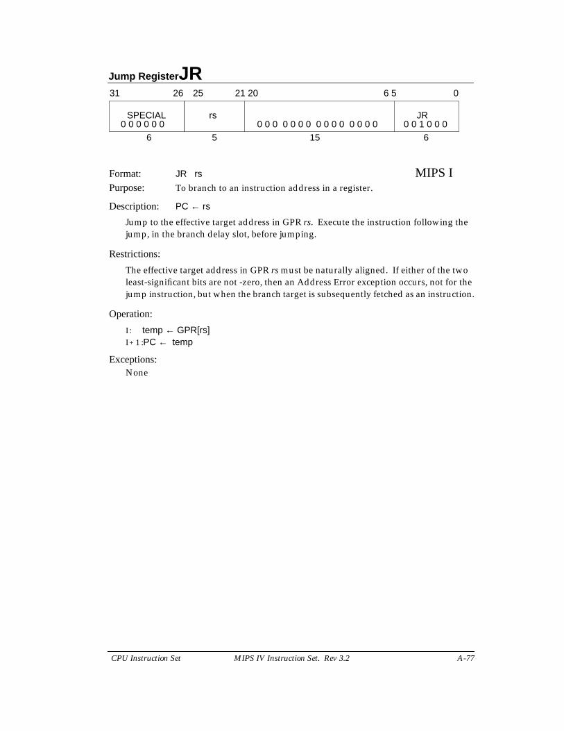
Jump Register JR
CPU Instruction Set MIPS IV Instruction Set. Rev 3.2 A-77
Format: JR rs MIPS IPurpose: To branch to an instruction address in a register.
Description: PC ← rs
Jump to the effective target address in GPR rs. Execute the instruction following thejump, in the branch delay slot, before jumping.
Restrictions:
The effective target address in GPR rs must be naturally aligned. If either of the twoleast-significant bits are not -zero, then an Address Error exception occurs, not for thejump instruction, but when the branch target is subsequently fetched as an instruction.
Operation:
I : temp ← GPR[rs]I + 1 :PC ← temp
Exceptions:None
21 2031 2526
SPECIAL
6
0
JRrs
6 5
5 15 60 0 0 0 0 0 0 0 0 0 0 0 0 0 0 0 0 0 0 0 0 0 0 1 0 0 0
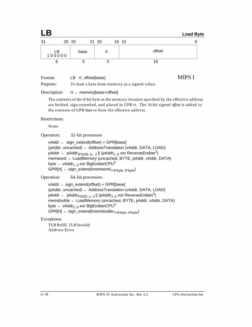
LB Load Byte
A-78 MIPS IV Instruction Set. Rev 3.2 CPU Instruction Set
Format: LB rt, offset(base) MIPS IPurpose: To load a byte from memory as a signed value.
Description: rt ← memory[base+offset]
The contents of the 8-bit byte at the memory location specified by the effective addressare fetched, sign-extended, and placed in GPR rt. The 16-bit signed offset is added tothe contents of GPR base to form the effective address.
Restrictions:
None
Operation: 32-bit processors
vAddr ← sign_extend(offset) + GPR[base](pAddr, uncached) ← AddressTranslation (vAddr, DATA, LOAD)pAddr ← pAddr(PSIZE-1).. 2 || (pAddr1..0 xor ReverseEndian2)memword ← LoadMemory (uncached, BYTE, pAddr, vAddr, DATA)byte ← vAddr1..0 xor BigEndianCPU2
GPR[rt] ← sign_extend(memword7+8*byte..8*byte)
Operation: 64-bit processors
vAddr ← sign_extend(offset) + GPR[base](pAddr, uncached) ← AddressTranslation (vAddr, DATA, LOAD)pAddr ← pAddrPSIZE–1..3 || (pAddr2..0 xor ReverseEndian3)memdouble ← LoadMemory (uncached, BYTE, pAddr, vAddr, DATA)byte ← vAddr2..0 xor BigEndianCPU3
GPR[rt] ← sign_extend(memdouble7+8*byte..8*byte)
Exceptions:TLB Refill, TLB InvalidAddress Error
31 2526 2021 1516 0
LB base rt offset
6 5 5 161 0 0 0 0 0
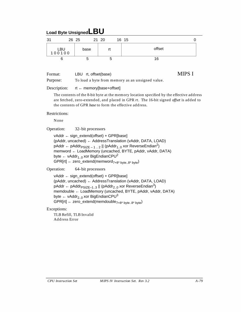
Load Byte Unsigned LBU
CPU Instruction Set MIPS IV Instruction Set. Rev 3.2 A-79
Format: LBU rt, offset(base) MIPS IPurpose: To load a byte from memory as an unsigned value.
Description: rt ← memory[base+offset]
The contents of the 8-bit byte at the memory location specified by the effective addressare fetched, zero-extended, and placed in GPR rt. The 16-bit signed offset is added tothe contents of GPR base to form the effective address.
Restrictions:
None
Operation: 32-bit processors
vAddr ← sign_extend(offset) + GPR[base](pAddr, uncached) ← AddressTranslation (vAddr, DATA, LOAD)pAddr ← pAddrPSIZE – 1 .. 2 || (pAddr1..0 xor ReverseEndian2)memword ← LoadMemory (uncached, BYTE, pAddr, vAddr, DATA)byte ← vAddr1..0 xor BigEndianCPU2
GPR[rt] ← zero_extend(memword7+8* byte..8* byte)
Operation: 64-bit processors
vAddr ← sign_extend(offset) + GPR[base](pAddr, uncached) ← AddressTranslation (vAddr, DATA, LOAD)pAddr ← pAddrPSIZE–1..3 || (pAddr2..0 xor ReverseEndian3)memdouble ← LoadMemory (uncached, BYTE, pAddr, vAddr, DATA)byte ← vAddr2..0 xor BigEndianCPU3
GPR[rt] ← zero_extend(memdouble7+8* byte..8* byte)
Exceptions:TLB Refill, TLB InvalidAddress Error
31 2526 2021 1516 0
LBU base rt offset
6 5 5 161 0 0 1 0 0
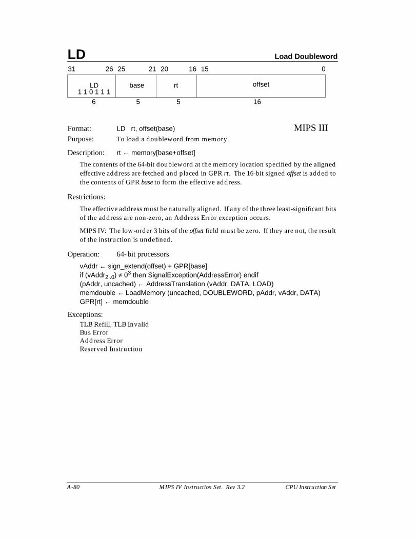
LD Load Doubleword
A-80 MIPS IV Instruction Set. Rev 3.2 CPU Instruction Set
Format: LD rt, offset(base) MIPS IIIPurpose: To load a doubleword from memory.
Description: rt ← memory[base+offset]
The contents of the 64-bit doubleword at the memory location specified by the alignedeffective address are fetched and placed in GPR rt. The 16-bit signed offset is added tothe contents of GPR base to form the effective address.
Restrictions:
The effective address must be naturally aligned. If any of the three least-significant bitsof the address are non-zero, an Address Error exception occurs.
MIPS IV: The low-order 3 bits of the offset field must be zero. If they are not, the resultof the instruction is undefined.
Operation: 64-bit processors
vAddr ← sign_extend(offset) + GPR[base]if (vAddr2..0) ≠ 03 then SignalException(AddressError) endif(pAddr, uncached) ← AddressTranslation (vAddr, DATA, LOAD)memdouble ← LoadMemory (uncached, DOUBLEWORD, pAddr, vAddr, DATA)GPR[rt] ← memdouble
Exceptions:TLB Refill, TLB InvalidBus ErrorAddress ErrorReserved Instruction
31 2526 2021 1516 0
LD base rt offset
6 5 5 161 1 0 1 1 1
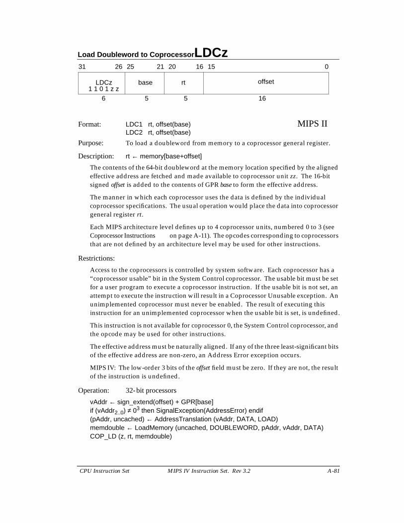
Load Doubleword to Coprocessor LDCz
CPU Instruction Set MIPS IV Instruction Set. Rev 3.2 A-81
Format: LDC1 rt, offset(base) MIPS IILDC2 rt, offset(base)
Purpose: To load a doubleword from memory to a coprocessor general register.
Description: rt ← memory[base+offset]
The contents of the 64-bit doubleword at the memory location specified by the alignedeffective address are fetched and made available to coprocessor unit zz. The 16-bitsigned offset is added to the contents of GPR base to form the effective address.
The manner in which each coprocessor uses the data is defined by the individualcoprocessor specifications. The usual operation would place the data into coprocessorgeneral register rt.
Each MIPS architecture level defines up to 4 coprocessor units, numbered 0 to 3 (seeCoprocessor Instructions on page A-11). The opcodes corresponding to coprocessorsthat are not defined by an architecture level may be used for other instructions.
Restrictions:
Access to the coprocessors is controlled by system software. Each coprocessor has a“coprocessor usable” bit in the System Control coprocessor. The usable bit must be setfor a user program to execute a coprocessor instruction. If the usable bit is not set, anattempt to execute the instruction will result in a Coprocessor Unusable exception. Anunimplemented coprocessor must never be enabled. The result of executing thisinstruction for an unimplemented coprocessor when the usable bit is set, is undefined.
This instruction is not available for coprocessor 0, the System Control coprocessor, andthe opcode may be used for other instructions.
The effective address must be naturally aligned. If any of the three least-significant bitsof the effective address are non-zero, an Address Error exception occurs.
MIPS IV: The low-order 3 bits of the offset field must be zero. If they are not, the resultof the instruction is undefined.
Operation: 32-bit processors
vAddr ← sign_extend(offset) + GPR[base]if (vAddr2..0) ≠ 03 then SignalException(AddressError) endif(pAddr, uncached) ← AddressTranslation (vAddr, DATA, LOAD)memdouble ← LoadMemory (uncached, DOUBLEWORD, pAddr, vAddr, DATA)COP_LD (z, rt, memdouble)
31 2526 2021 1516 0
LDCz base rt offset
6 5 5 161 1 0 1 z z
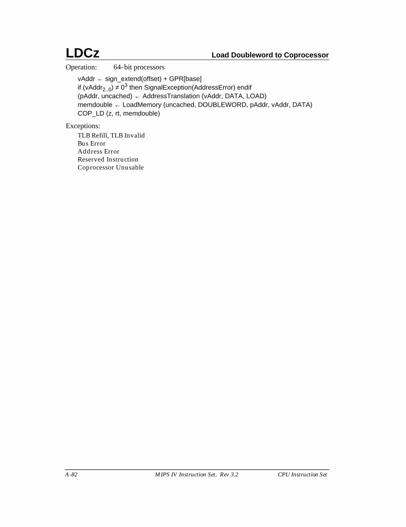
LDCz Load Doubleword to Coprocessor
A-82 MIPS IV Instruction Set. Rev 3.2 CPU Instruction Set
Operation: 64-bit processors
vAddr ← sign_extend(offset) + GPR[base]if (vAddr2..0) ≠ 03 then SignalException(AddressError) endif(pAddr, uncached) ← AddressTranslation (vAddr, DATA, LOAD)memdouble ← LoadMemory (uncached, DOUBLEWORD, pAddr, vAddr, DATA)COP_LD (z, rt, memdouble)
Exceptions:TLB Refill, TLB InvalidBus ErrorAddress ErrorReserved InstructionCoprocessor Unusable
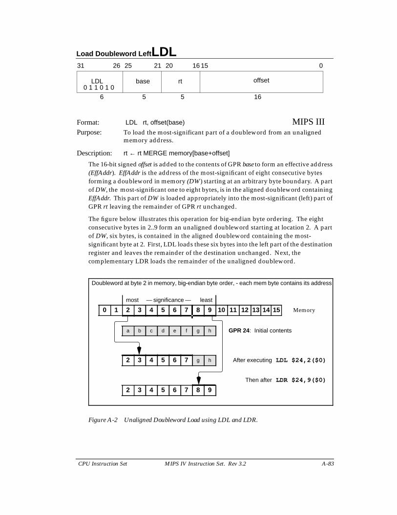
Load Doubleword Left LDL
CPU Instruction Set MIPS IV Instruction Set. Rev 3.2 A-83
Format: LDL rt, offset(base) MIPS IIIPurpose: To load the most-significant part of a doubleword from an unaligned
memory address.
Description: rt ← rt MERGE memory[base+offset]
The 16-bit signed offset is added to the contents of GPR base to form an effective address(EffAddr). EffAddr is the address of the most-significant of eight consecutive bytesforming a doubleword in memory (DW) starting at an arbitrary byte boundary. A partof DW, the most-significant one to eight bytes, is in the aligned doubleword containingEffAddr. This part of DW is loaded appropriately into the most-significant (left) part ofGPR rt leaving the remainder of GPR rt unchanged.
The figure below illustrates this operation for big-endian byte ordering. The eightconsecutive bytes in 2..9 form an unaligned doubleword starting at location 2. A partof DW, six bytes, is contained in the aligned doubleword containing the most-significant byte at 2. First, LDL loads these six bytes into the left part of the destinationregister and leaves the remainder of the destination unchanged. Next, thecomplementary LDR loads the remainder of the unaligned doubleword.
Figure A-2 Unaligned Doubleword Load using LDL and LDR.
31 2526 2021 1516 0
LDL base rt offset
6 5 5 160 1 1 0 1 0
Doubleword at byte 2 in memory, big-endian byte order, - each mem byte contains its address
most — significance — least
0 1 2 3 4 5 6 7 8 9 10 11 12 13 14 15 Memory
a b c d e f g h GPR 24: Initial contents
2 3 4 5 6 7 g h After executing LDL $24,2($0)
Then after LDR $24,9($0)
2 3 4 5 6 7 8 9
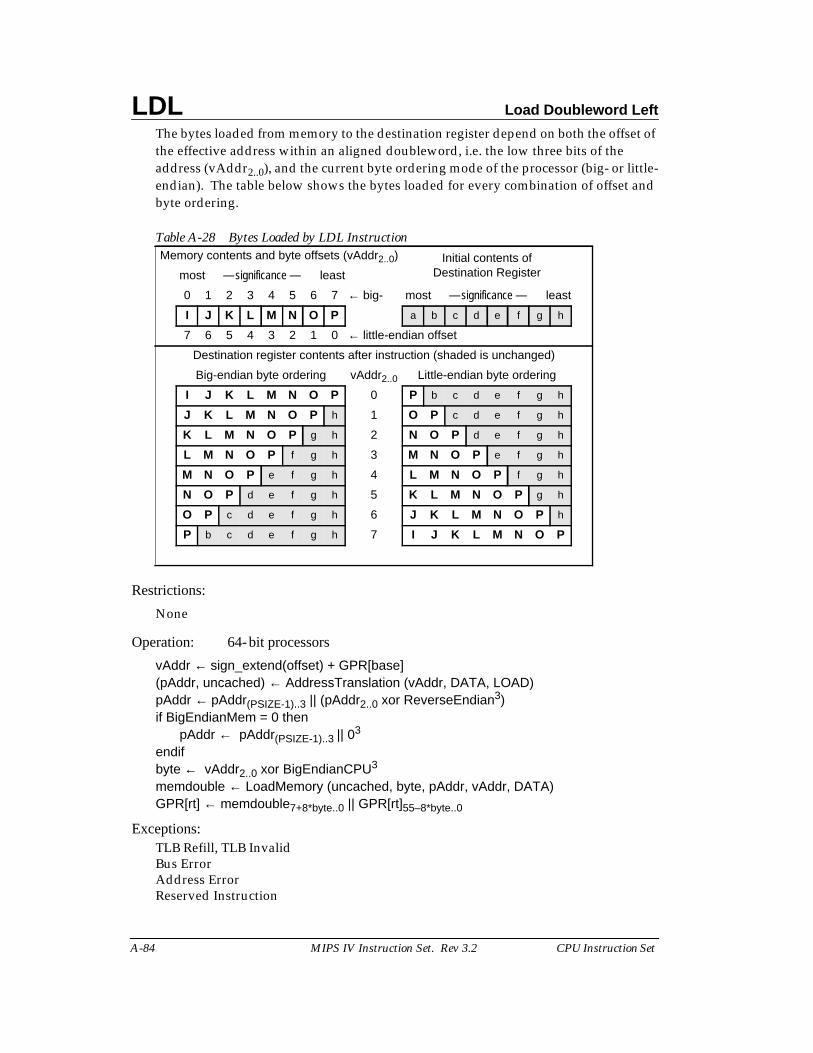
LDL Load Doubleword Left
A-84 MIPS IV Instruction Set. Rev 3.2 CPU Instruction Set
The bytes loaded from memory to the destination register depend on both the offset ofthe effective address within an aligned doubleword, i.e. the low three bits of theaddress (vAddr2..0), and the current byte ordering mode of the processor (big- or little-endian). The table below shows the bytes loaded for every combination of offset andbyte ordering.
Restrictions:
None
Operation: 64-bit processors
vAddr ← sign_extend(offset) + GPR[base](pAddr, uncached) ← AddressTranslation (vAddr, DATA, LOAD)pAddr ← pAddr(PSIZE-1)..3 || (pAddr2..0 xor ReverseEndian3)if BigEndianMem = 0 then
pAddr ← pAddr(PSIZE-1)..3 || 03
endifbyte ← vAddr2..0 xor BigEndianCPU3
memdouble ← LoadMemory (uncached, byte, pAddr, vAddr, DATA)GPR[rt] ← memdouble7+8*byte..0 || GPR[rt]55–8*byte..0
Exceptions:TLB Refill, TLB InvalidBus ErrorAddress ErrorReserved Instruction
Table A-28 Bytes Loaded by LDL InstructionMemory contents and byte offsets (vAddr2..0) Initial contents of
Destination Registermost — significance — least
0 1 2 3 4 5 6 7 ← big- most — significance — least
I J K L M N O P a b c d e f g h
7 6 5 4 3 2 1 0 ← little-endian offset
Destination register contents after instruction (shaded is unchanged)
Big-endian byte ordering vAddr2..0 Little-endian byte ordering
I J K L M N O P 0 P b c d e f g h
J K L M N O P h 1 O P c d e f g h
K L M N O P g h 2 N O P d e f g h
L M N O P f g h 3 M N O P e f g h
M N O P e f g h 4 L M N O P f g h
N O P d e f g h 5 K L M N O P g h
O P c d e f g h 6 J K L M N O P h
P b c d e f g h 7 I J K L M N O P
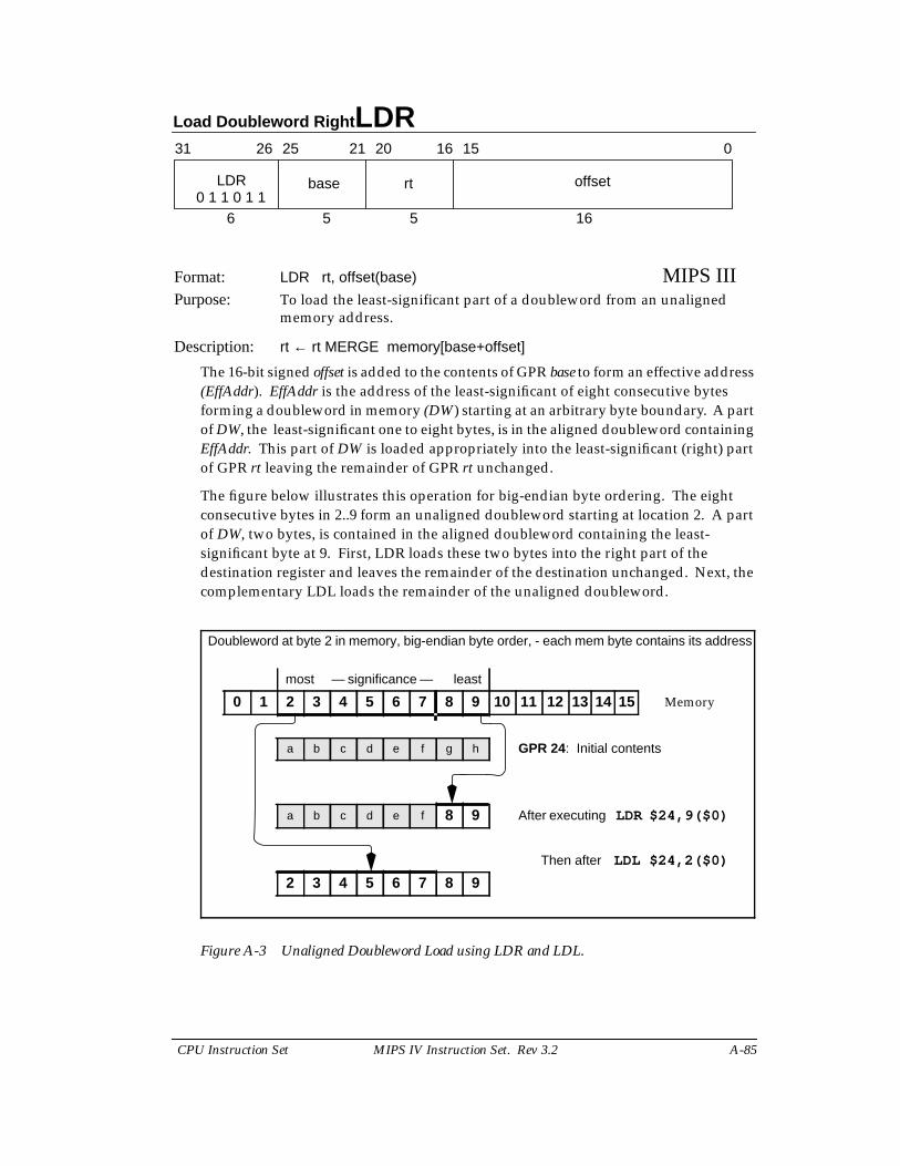
Load Doubleword Right LDR
CPU Instruction Set MIPS IV Instruction Set. Rev 3.2 A-85
Format: LDR rt, offset(base) MIPS IIIPurpose: To load the least-significant part of a doubleword from an unaligned
memory address.
Description: rt ← rt MERGE memory[base+offset]
The 16-bit signed offset is added to the contents of GPR base to form an effective address(EffAddr). EffAddr is the address of the least-significant of eight consecutive bytesforming a doubleword in memory (DW) starting at an arbitrary byte boundary. A partof DW, the least-significant one to eight bytes, is in the aligned doubleword containingEffAddr. This part of DW is loaded appropriately into the least-significant (right) partof GPR rt leaving the remainder of GPR rt unchanged.
The figure below illustrates this operation for big-endian byte ordering. The eightconsecutive bytes in 2..9 form an unaligned doubleword starting at location 2. A partof DW, two bytes, is contained in the aligned doubleword containing the least-significant byte at 9. First, LDR loads these two bytes into the right part of thedestination register and leaves the remainder of the destination unchanged. Next, thecomplementary LDL loads the remainder of the unaligned doubleword.
Figure A-3 Unaligned Doubleword Load using LDR and LDL.
31 2526 2021 1516 0
LDR base rt offset
6 5 5 160 1 1 0 1 1
Doubleword at byte 2 in memory, big-endian byte order, - each mem byte contains its address
most — significance — least
0 1 2 3 4 5 6 7 8 9 10 11 12 13 14 15 Memory
a b c d e f g h GPR 24: Initial contents
a b c d e f 8 9 After executing LDR $24,9($0)
Then after LDL $24,2($0)
2 3 4 5 6 7 8 9
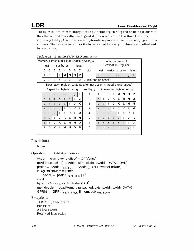
LDR Load Doubleword Right
A-86 MIPS IV Instruction Set. Rev 3.2 CPU Instruction Set
The bytes loaded from memory to the destination register depend on both the offset ofthe effective address within an aligned doubleword, i.e. the low three bits of theaddress (vAddr2..0), and the current byte ordering mode of the processor (big- or little-endian). The table below shows the bytes loaded for every combination of offset andbyte ordering.
Restrictions:
None
Operation: 64-bit processors
vAddr ← sign_extend(offset) + GPR[base](pAddr, uncached) ← AddressTranslation (vAddr, DATA, LOAD)pAddr ← pAddr(PSIZE-1)..3 || (pAddr2..0 xor ReverseEndian3)if BigEndianMem = 1 then
pAddr ← pAddr(PSIZE-1)..3 || 03
endifbyte ← vAddr2..0 xor BigEndianCPU3
memdouble ← LoadMemory (uncached, byte, pAddr, vAddr, DATA)GPR[rt] ← GPR[rt]63..64-8*byte || memdouble63..8*byte
Exceptions:TLB Refill, TLB InvalidBus ErrorAddress ErrorReserved Instruction
Table A-29 Bytes Loaded by LDR InstructionMemory contents and byte offsets (vAddr2..0) Initial contents of
Destination Registermost — significance — least
0 1 2 3 4 5 6 7 ← big- most — significance — least
I J K L M N O P a b c d e f g h
7 6 5 4 3 2 1 0 ← little-endian offset
Destination register contents after instruction (shaded is unchanged)
Big-endian byte ordering vAddr2..0 Little-endian byte ordering
a b c d e f g I 0 I J K L M N O P
a b c d e f I J 1 a I J K L M N O
a b c d e I J K 2 a b I J K L M N
a b c d I J K L 3 a b c I J K L M
a b c I J K L M 4 a b c d I J K L
a b I J K L M N 5 a b c d e I J K
a I J K L M N O 6 a b c d e f I J
I J K L M N O P 7 a b c d e f g I
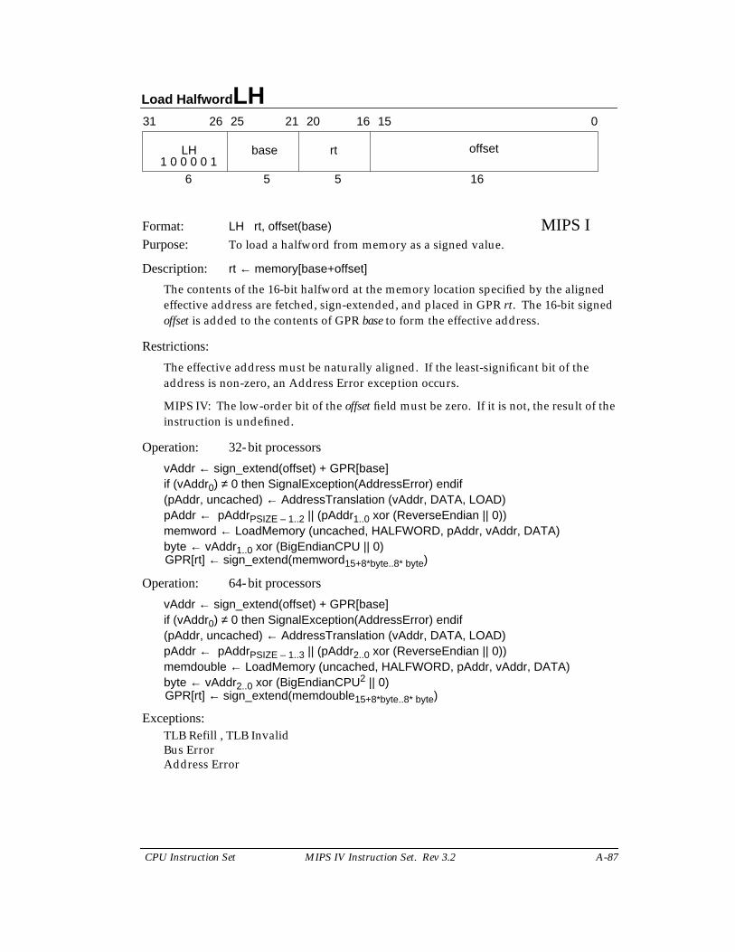
Load Halfword LH
CPU Instruction Set MIPS IV Instruction Set. Rev 3.2 A-87
Format: LH rt, offset(base) MIPS IPurpose: To load a halfword from memory as a signed value.
Description: rt ← memory[base+offset]
The contents of the 16-bit halfword at the memory location specified by the alignedeffective address are fetched, sign-extended, and placed in GPR rt. The 16-bit signedoffset is added to the contents of GPR base to form the effective address.
Restrictions:
The effective address must be naturally aligned. If the least-significant bit of theaddress is non-zero, an Address Error exception occurs.
MIPS IV: The low-order bit of the offset field must be zero. If it is not, the result of theinstruction is undefined.
Operation: 32-bit processors
vAddr ← sign_extend(offset) + GPR[base]if (vAddr0) ≠ 0 then SignalException(AddressError) endif(pAddr, uncached) ← AddressTranslation (vAddr, DATA, LOAD)pAddr ← pAddrPSIZE – 1..2 || (pAddr1..0 xor (ReverseEndian || 0))memword ← LoadMemory (uncached, HALFWORD, pAddr, vAddr, DATA)byte ← vAddr1..0 xor (BigEndianCPU || 0)GPR[rt] ← sign_extend(memword15+8*byte..8* byte)
Operation: 64-bit processors
vAddr ← sign_extend(offset) + GPR[base]if (vAddr0) ≠ 0 then SignalException(AddressError) endif(pAddr, uncached) ← AddressTranslation (vAddr, DATA, LOAD)pAddr ← pAddrPSIZE – 1..3 || (pAddr2..0 xor (ReverseEndian || 0))memdouble ← LoadMemory (uncached, HALFWORD, pAddr, vAddr, DATA)byte ← vAddr2..0 xor (BigEndianCPU2 || 0)GPR[rt] ← sign_extend(memdouble15+8*byte..8* byte)
Exceptions:TLB Refill , TLB InvalidBus ErrorAddress Error
31 2526 2021 1516 0
LH base rt offset
6 5 5 161 0 0 0 0 1
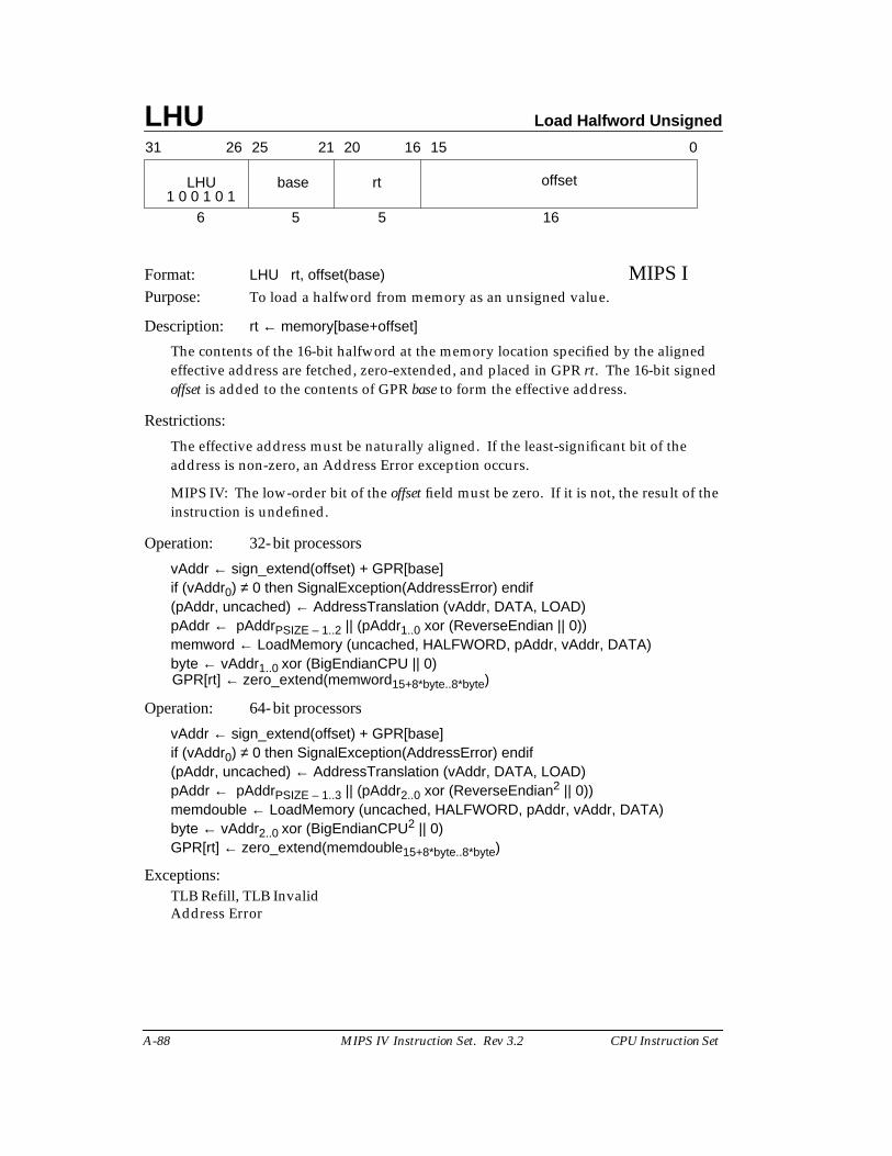
LHU Load Halfword Unsigned
A-88 MIPS IV Instruction Set. Rev 3.2 CPU Instruction Set
Format: LHU rt, offset(base) MIPS IPurpose: To load a halfword from memory as an unsigned value.
Description: rt ← memory[base+offset]
The contents of the 16-bit halfword at the memory location specified by the alignedeffective address are fetched, zero-extended, and placed in GPR rt. The 16-bit signedoffset is added to the contents of GPR base to form the effective address.
Restrictions:
The effective address must be naturally aligned. If the least-significant bit of theaddress is non-zero, an Address Error exception occurs.
MIPS IV: The low-order bit of the offset field must be zero. If it is not, the result of theinstruction is undefined.
Operation: 32-bit processors
vAddr ← sign_extend(offset) + GPR[base]if (vAddr0) ≠ 0 then SignalException(AddressError) endif(pAddr, uncached) ← AddressTranslation (vAddr, DATA, LOAD)pAddr ← pAddrPSIZE – 1..2 || (pAddr1..0 xor (ReverseEndian || 0))memword ← LoadMemory (uncached, HALFWORD, pAddr, vAddr, DATA)byte ← vAddr1..0 xor (BigEndianCPU || 0)GPR[rt] ← zero_extend(memword15+8*byte..8*byte)
Operation: 64-bit processors
vAddr ← sign_extend(offset) + GPR[base]if (vAddr0) ≠ 0 then SignalException(AddressError) endif(pAddr, uncached) ← AddressTranslation (vAddr, DATA, LOAD)pAddr ← pAddrPSIZE – 1..3 || (pAddr2..0 xor (ReverseEndian2 || 0))memdouble ← LoadMemory (uncached, HALFWORD, pAddr, vAddr, DATA)byte ← vAddr2..0 xor (BigEndianCPU2 || 0)GPR[rt] ← zero_extend(memdouble15+8*byte..8*byte)
Exceptions:TLB Refill, TLB InvalidAddress Error
31 2526 2021 1516 0
LHU base rt offset
6 5 5 161 0 0 1 0 1
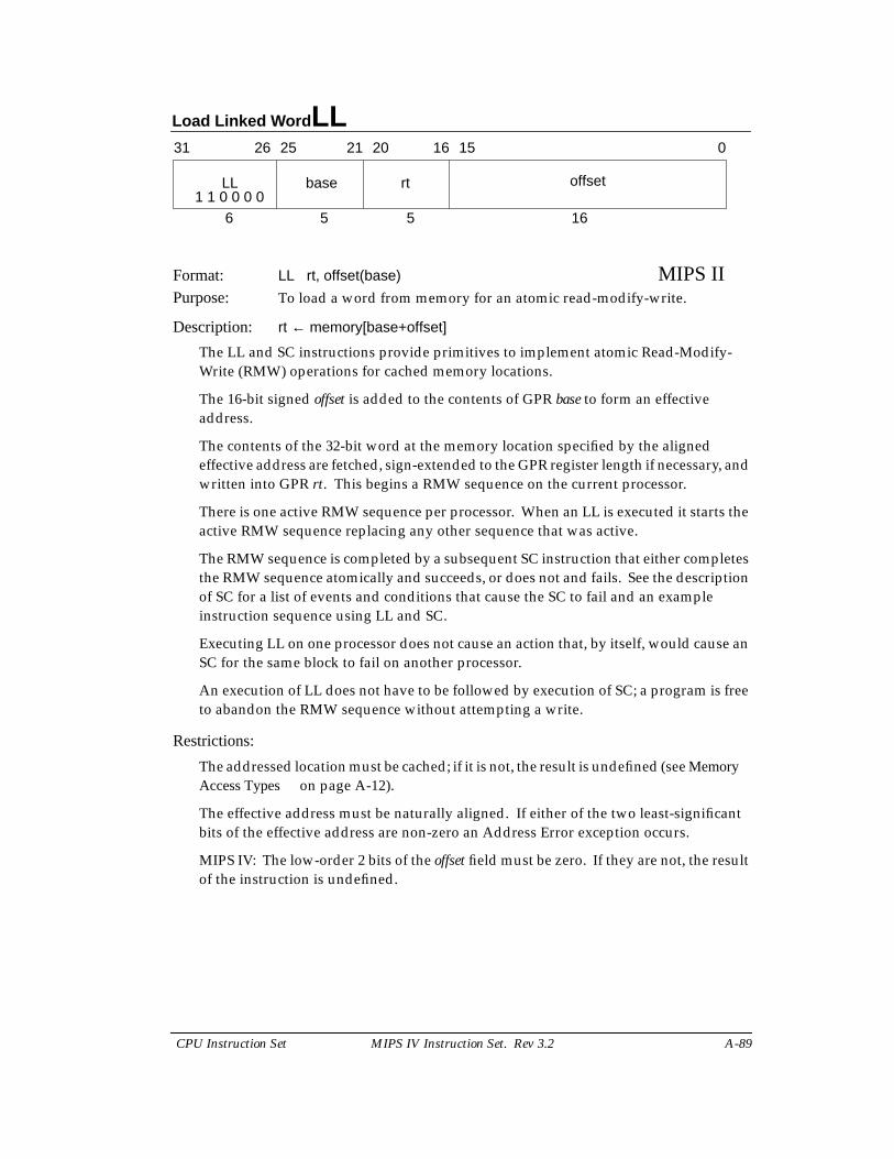
Load Linked Word LL
CPU Instruction Set MIPS IV Instruction Set. Rev 3.2 A-89
Format: LL rt, offset(base) MIPS IIPurpose: To load a word from memory for an atomic read-modify-write.
Description: rt ← memory[base+offset]
The LL and SC instructions provide primitives to implement atomic Read-Modify-Write (RMW) operations for cached memory locations.
The 16-bit signed offset is added to the contents of GPR base to form an effectiveaddress.
The contents of the 32-bit word at the memory location specified by the alignedeffective address are fetched, sign-extended to the GPR register length if necessary, andwritten into GPR rt. This begins a RMW sequence on the current processor.
There is one active RMW sequence per processor. When an LL is executed it starts theactive RMW sequence replacing any other sequence that was active.
The RMW sequence is completed by a subsequent SC instruction that either completesthe RMW sequence atomically and succeeds, or does not and fails. See the descriptionof SC for a list of events and conditions that cause the SC to fail and an exampleinstruction sequence using LL and SC.
Executing LL on one processor does not cause an action that, by itself, would cause anSC for the same block to fail on another processor.
An execution of LL does not have to be followed by execution of SC; a program is freeto abandon the RMW sequence without attempting a write.
Restrictions:
The addressed location must be cached; if it is not, the result is undefined (see MemoryAccess Types on page A-12).
The effective address must be naturally aligned. If either of the two least-significantbits of the effective address are non-zero an Address Error exception occurs.
MIPS IV: The low-order 2 bits of the offset field must be zero. If they are not, the resultof the instruction is undefined.
31 2526 2021 1516 0
LL base rt offset
6 5 5 161 1 0 0 0 0
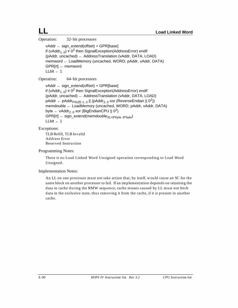
LL Load Linked Word
A-90 MIPS IV Instruction Set. Rev 3.2 CPU Instruction Set
Operation: 32-bit processors
vAddr ← sign_extend(offset) + GPR[base]if (vAddr1..0) ≠ 02 then SignalException(AddressError) endif(pAddr, uncached) ← AddressTranslation (vAddr, DATA, LOAD)memword ← LoadMemory (uncached, WORD, pAddr, vAddr, DATA)GPR[rt] ← memwordLLbit ← 1
Operation: 64-bit processors
vAddr ← sign_extend(offset) + GPR[base]if (vAddr1..0) ≠ 02 then SignalException(AddressError) endif(pAddr, uncached) ← AddressTranslation (vAddr, DATA, LOAD)pAddr ← pAddrPSIZE-1..3 || (pAddr2..0 xor (ReverseEndian || 02))memdouble ← LoadMemory (uncached, WORD, pAddr, vAddr, DATA)byte ← vAddr2..0 xor (BigEndianCPU || 02)GPR[rt] ← sign_extend(memdouble31+8*byte..8*byte)LLbit ← 1
Exceptions:TLB Refill, TLB InvalidAddress ErrorReserved Instruction
Programming Notes:
There is no Load Linked Word Unsigned operation corresponding to Load WordUnsigned.
Implementation Notes:
An LL on one processor must not take action that, by itself, would cause an SC for thesame block on another processor to fail. If an implementation depends on retaining thedata in cache during the RMW sequence, cache misses caused by LL must not fetchdata in the exclusive state, thus removing it from the cache, if it is present in anothercache.
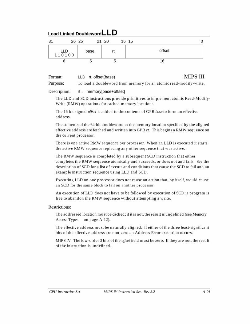
Load Linked Doubleword LLD
CPU Instruction Set MIPS IV Instruction Set. Rev 3.2 A-91
Format: LLD rt, offset(base) MIPS IIIPurpose: To load a doubleword from memory for an atomic read-modify-write.
Description: rt ← memory[base+offset]
The LLD and SCD instructions provide primitives to implement atomic Read-Modify-Write (RMW) operations for cached memory locations.
The 16-bit signed offset is added to the contents of GPR base to form an effectiveaddress.
The contents of the 64-bit doubleword at the memory location specified by the alignedeffective address are fetched and written into GPR rt. This begins a RMW sequence onthe current processor.
There is one active RMW sequence per processor. When an LLD is executed it startsthe active RMW sequence replacing any other sequence that was active.
The RMW sequence is completed by a subsequent SCD instruction that eithercompletes the RMW sequence atomically and succeeds, or does not and fails. See thedescription of SCD for a list of events and conditions that cause the SCD to fail and anexample instruction sequence using LLD and SCD.
Executing LLD on one processor does not cause an action that, by itself, would causean SCD for the same block to fail on another processor.
An execution of LLD does not have to be followed by execution of SCD; a program isfree to abandon the RMW sequence without attempting a write.
Restrictions:
The addressed location must be cached; if it is not, the result is undefined (see MemoryAccess Types on page A-12).
The effective address must be naturally aligned. If either of the three least-significantbits of the effective address are non-zero an Address Error exception occurs.
MIPS IV: The low-order 3 bits of the offset field must be zero. If they are not, the resultof the instruction is undefined.
31 2526 2021 1516 0
LLD base rt offset
6 5 5 161 1 0 1 0 0
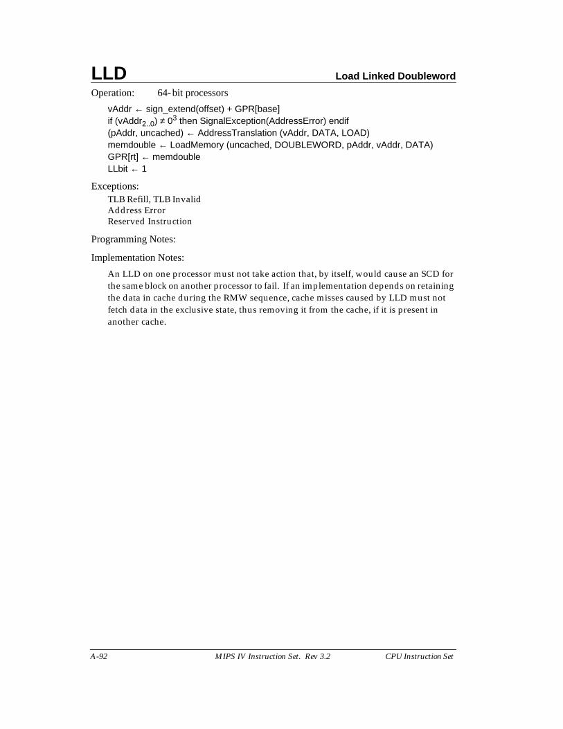
LLD Load Linked Doubleword
A-92 MIPS IV Instruction Set. Rev 3.2 CPU Instruction Set
Operation: 64-bit processors
vAddr ← sign_extend(offset) + GPR[base]if (vAddr2..0) ≠ 03 then SignalException(AddressError) endif(pAddr, uncached) ← AddressTranslation (vAddr, DATA, LOAD)memdouble ← LoadMemory (uncached, DOUBLEWORD, pAddr, vAddr, DATA)GPR[rt] ← memdoubleLLbit ← 1
Exceptions:TLB Refill, TLB InvalidAddress ErrorReserved Instruction
Programming Notes:
Implementation Notes:
An LLD on one processor must not take action that, by itself, would cause an SCD forthe same block on another processor to fail. If an implementation depends on retainingthe data in cache during the RMW sequence, cache misses caused by LLD must notfetch data in the exclusive state, thus removing it from the cache, if it is present inanother cache.
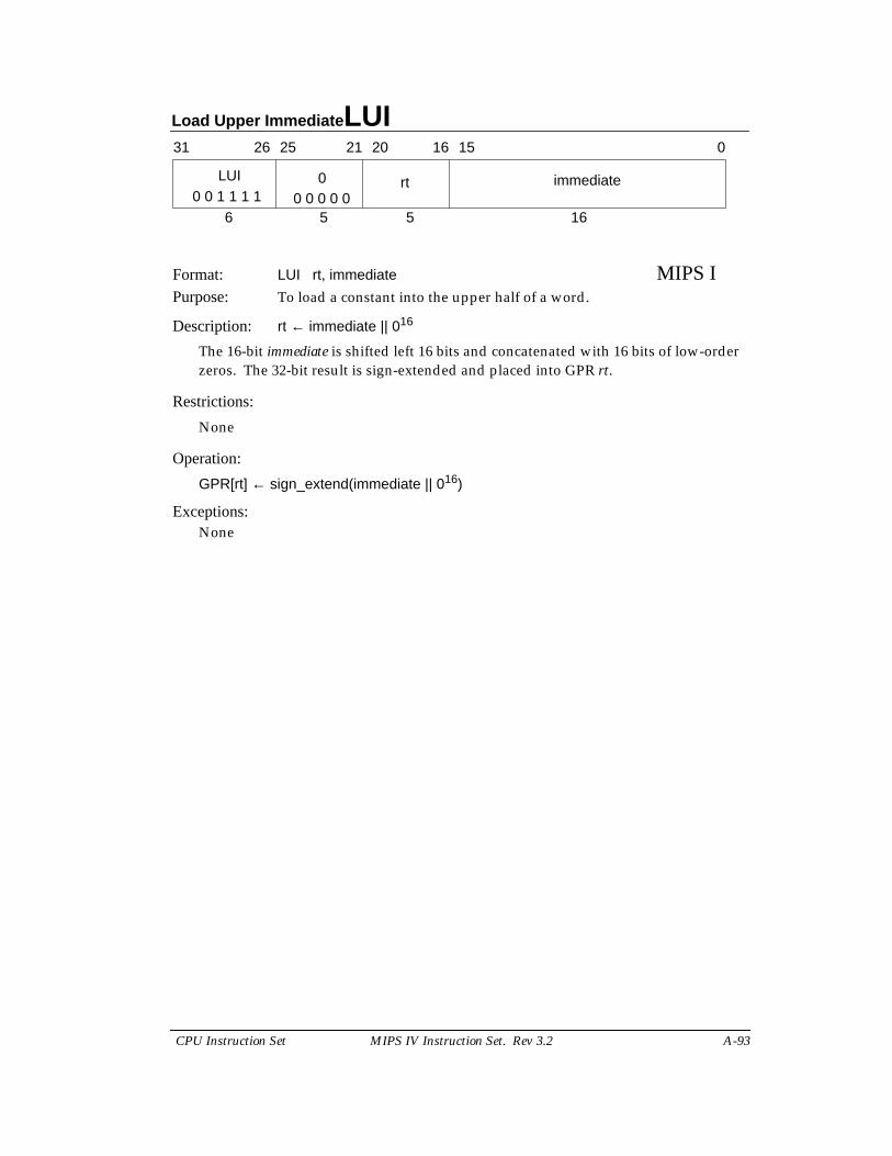
Load Upper Immediate LUI
CPU Instruction Set MIPS IV Instruction Set. Rev 3.2 A-93
Format: LUI rt, immediate MIPS IPurpose: To load a constant into the upper half of a word.
Description: rt ← immediate || 016
The 16-bit immediate is shifted left 16 bits and concatenated with 16 bits of low-orderzeros. The 32-bit result is sign-extended and placed into GPR rt.
Restrictions:
None
Operation:
GPR[rt] ← sign_extend(immediate || 016)
Exceptions:None
31 2526 2021 1516 0
LUI rt immediate
6 5 5 160 0 1 1 1 1
00 0 0 0 0
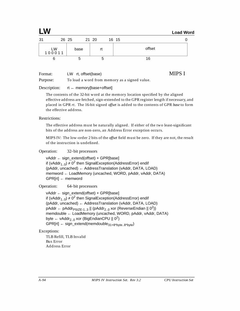
LW Load Word
A-94 MIPS IV Instruction Set. Rev 3.2 CPU Instruction Set
Format: LW rt, offset(base) MIPS IPurpose: To load a word from memory as a signed value.
Description: rt ← memory[base+offset]
The contents of the 32-bit word at the memory location specified by the alignedeffective address are fetched, sign-extended to the GPR register length if necessary, andplaced in GPR rt. The 16-bit signed offset is added to the contents of GPR base to formthe effective address.
Restrictions:
The effective address must be naturally aligned. If either of the two least-significantbits of the address are non-zero, an Address Error exception occurs.
MIPS IV: The low-order 2 bits of the offset field must be zero. If they are not, the resultof the instruction is undefined.
Operation: 32-bit processors
vAddr ← sign_extend(offset) + GPR[base]if (vAddr1..0) ≠ 02 then SignalException(AddressError) endif(pAddr, uncached) ← AddressTranslation (vAddr, DATA, LOAD)memword ← LoadMemory (uncached, WORD, pAddr, vAddr, DATA)GPR[rt] ← memword
Operation: 64-bit processors
vAddr ← sign_extend(offset) + GPR[base]if (vAddr1..0) ≠ 02 then SignalException(AddressError) endif(pAddr, uncached) ← AddressTranslation (vAddr, DATA, LOAD)pAddr ← pAddrPSIZE-1..3 || (pAddr2..0 xor (ReverseEndian || 02))memdouble ← LoadMemory (uncached, WORD, pAddr, vAddr, DATA)byte ← vAddr2..0 xor (BigEndianCPU || 02)GPR[rt] ← sign_extend(memdouble31+8*byte..8*byte)
Exceptions:TLB Refill, TLB InvalidBus ErrorAddress Error
31 2526 2021 1516 0
LW base rt offset
6 5 5 161 0 0 0 1 1
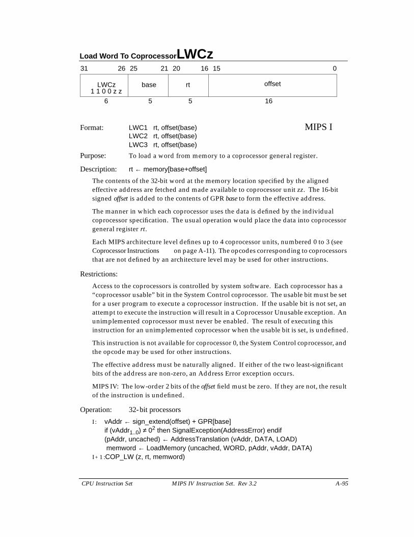
Load Word To Coprocessor LWCz
CPU Instruction Set MIPS IV Instruction Set. Rev 3.2 A-95
Format: LWC1 rt, offset(base) MIPS ILWC2 rt, offset(base)LWC3 rt, offset(base)
Purpose: To load a word from memory to a coprocessor general register.
Description: rt ← memory[base+offset]
The contents of the 32-bit word at the memory location specified by the alignedeffective address are fetched and made available to coprocessor unit zz. The 16-bitsigned offset is added to the contents of GPR base to form the effective address.
The manner in which each coprocessor uses the data is defined by the individualcoprocessor specification. The usual operation would place the data into coprocessorgeneral register rt.
Each MIPS architecture level defines up to 4 coprocessor units, numbered 0 to 3 (seeCoprocessor Instructions on page A-11). The opcodes corresponding to coprocessorsthat are not defined by an architecture level may be used for other instructions.
Restrictions:
Access to the coprocessors is controlled by system software. Each coprocessor has a“coprocessor usable” bit in the System Control coprocessor. The usable bit must be setfor a user program to execute a coprocessor instruction. If the usable bit is not set, anattempt to execute the instruction will result in a Coprocessor Unusable exception. Anunimplemented coprocessor must never be enabled. The result of executing thisinstruction for an unimplemented coprocessor when the usable bit is set, is undefined.
This instruction is not available for coprocessor 0, the System Control coprocessor, andthe opcode may be used for other instructions.
The effective address must be naturally aligned. If either of the two least-significantbits of the address are non-zero, an Address Error exception occurs.
MIPS IV: The low-order 2 bits of the offset field must be zero. If they are not, the resultof the instruction is undefined.
Operation: 32-bit processors
I : vAddr ← sign_extend(offset) + GPR[base]if (vAddr1..0) ≠ 02 then SignalException(AddressError) endif(pAddr, uncached) ← AddressTranslation (vAddr, DATA, LOAD) memword ← LoadMemory (uncached, WORD, pAddr, vAddr, DATA)
I + 1 :COP_LW (z, rt, memword)
31 2526 2021 1516 0
LWCz base rt offset
6 5 5 161 1 0 0 z z
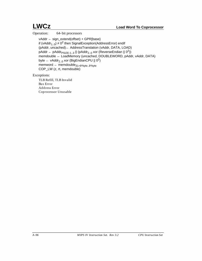
LWCz Load Word To Coprocessor
A-96 MIPS IV Instruction Set. Rev 3.2 CPU Instruction Set
Operation: 64-bit processors
vAddr ← sign_extend(offset) + GPR[base}if (vAddr1..0) ≠ 02 then SignalException(AddressError) endif(pAddr, uncached)← AddressTranslation (vAddr, DATA, LOAD)pAddr ← pAddrPSIZE-1..3 || (pAddr2..0 xor (ReverseEndian || 02))memdouble ← LoadMemory (uncached, DOUBLEWORD, pAddr, vAddr, DATA)byte ← vAddr2..0 xor (BigEndianCPU || 02)memword ← memdouble31+8*byte..8*byteCOP_LW (z, rt, memdouble)
Exceptions:TLB Refill, TLB InvalidBus ErrorAddress ErrorCoprocessor Unusable
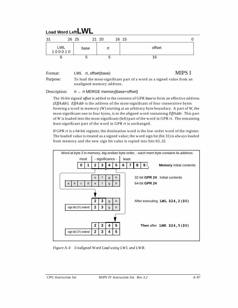
Load Word Left LWL
CPU Instruction Set MIPS IV Instruction Set. Rev 3.2 A-97
Format: LWL rt, offset(base) MIPS IPurpose: To load the most-significant part of a word as a signed value from an
unaligned memory address.
Description: rt ← rt MERGE memory[base+offset]
The 16-bit signed offset is added to the contents of GPR base to form an effective address(EffAddr). EffAddr is the address of the most-significant of four consecutive bytesforming a word in memory (W) starting at an arbitrary byte boundary. A part of W, themost-significant one to four bytes, is in the aligned word containing EffAddr. This partof W is loaded into the most-significant (left) part of the word in GPR rt. The remainingleast-significant part of the word in GPR rt is unchanged.
If GPR rt is a 64-bit register, the destination word is the low-order word of the register.The loaded value is treated as a signed value; the word sign bit (bit 31) is always loadedfrom memory and the new sign bit value is copied into bits 63..32.
Figure A-4 Unaligned Word Load using LWL and LWR.
31 2526 2021 1516 0
LWL base rt offset
6 5 5 161 0 0 0 1 0
Word at byte 2 in memory, big-endian byte order, - each mem byte contains its address
most - significance - least
0 1 2 3 4 5 6 7 8 9 Memory initial contents
e f g h 32-bit GPR 24: Initial contents
a b c d e f g h 64-bit GPR 24
2 3 g h After executing LWL $24,2($0)
sign bit (31) extend 2 3 g h
2 3 4 5 Then after LWR $24,5($0)
sign bit (31) extend 2 3 4 5
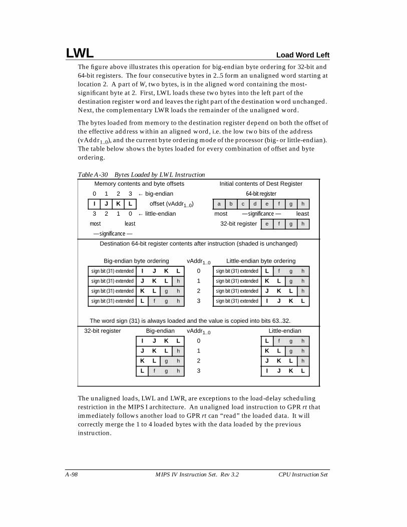
LWL Load Word Left
A-98 MIPS IV Instruction Set. Rev 3.2 CPU Instruction Set
The figure above illustrates this operation for big-endian byte ordering for 32-bit and64-bit registers. The four consecutive bytes in 2..5 form an unaligned word starting atlocation 2. A part of W, two bytes, is in the aligned word containing the most-significant byte at 2. First, LWL loads these two bytes into the left part of thedestination register word and leaves the right part of the destination word unchanged.Next, the complementary LWR loads the remainder of the unaligned word.
The bytes loaded from memory to the destination register depend on both the offset ofthe effective address within an aligned word, i.e. the low two bits of the address(vAddr1..0), and the current byte ordering mode of the processor (big- or little-endian).The table below shows the bytes loaded for every combination of offset and byteordering.
The unaligned loads, LWL and LWR, are exceptions to the load-delay schedulingrestriction in the MIPS I architecture. An unaligned load instruction to GPR rt thatimmediately follows another load to GPR rt can “read” the loaded data. It willcorrectly merge the 1 to 4 loaded bytes with the data loaded by the previousinstruction.
Table A-30 Bytes Loaded by LWL InstructionMemory contents and byte offsets Initial contents of Dest Register
0 1 2 3 ← big-endian 64-bit register
I J K L offset (vAddr1..0) a b c d e f g h
3 2 1 0 ← little-endian most — significance — least
most least 32-bit register e f g h
— significance —
Destination 64-bit register contents after instruction (shaded is unchanged)
Big-endian byte ordering vAddr1..0 Little-endian byte ordering
sign bit (31) extended I J K L 0 sign bit (31) extended L f g h
sign bit (31) extended J K L h 1 sign bit (31) extended K L g h
sign bit (31) extended K L g h 2 sign bit (31) extended J K L h
sign bit (31) extended L f g h 3 sign bit (31) extended I J K L
The word sign (31) is always loaded and the value is copied into bits 63..32.
32-bit register Big-endian vAddr1..0 Little-endian
I J K L 0 L f g h
J K L h 1 K L g h
K L g h 2 J K L h
L f g h 3 I J K L
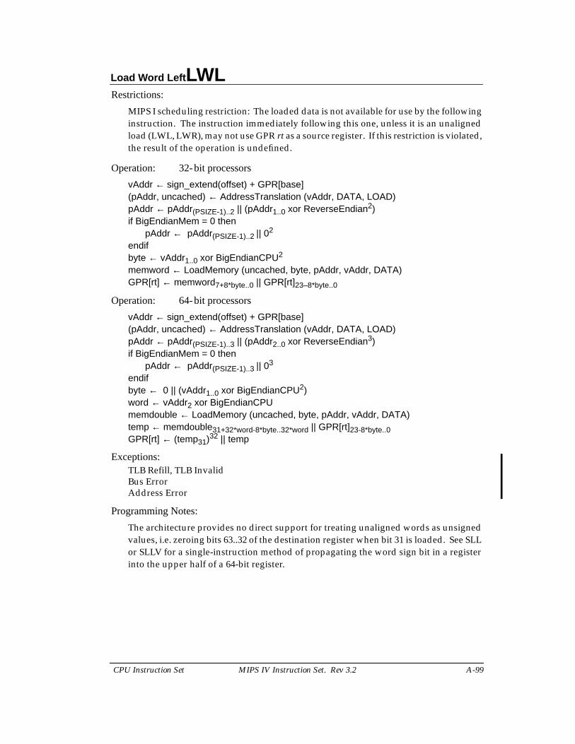
Load Word Left LWL
CPU Instruction Set MIPS IV Instruction Set. Rev 3.2 A-99
Restrictions:
MIPS I scheduling restriction: The loaded data is not available for use by the followinginstruction. The instruction immediately following this one, unless it is an unalignedload (LWL, LWR), may not use GPR rt as a source register. If this restriction is violated,the result of the operation is undefined.
Operation: 32-bit processors
vAddr ← sign_extend(offset) + GPR[base](pAddr, uncached) ← AddressTranslation (vAddr, DATA, LOAD)pAddr ← pAddr(PSIZE-1)..2 || (pAddr1..0 xor ReverseEndian2)if BigEndianMem = 0 then
pAddr ← pAddr(PSIZE-1)..2 || 02
endifbyte ← vAddr1..0 xor BigEndianCPU2
memword ← LoadMemory (uncached, byte, pAddr, vAddr, DATA)GPR[rt] ← memword7+8*byte..0 || GPR[rt]23–8*byte..0
Operation: 64-bit processors
vAddr ← sign_extend(offset) + GPR[base](pAddr, uncached) ← AddressTranslation (vAddr, DATA, LOAD)pAddr ← pAddr(PSIZE-1)..3 || (pAddr2..0 xor ReverseEndian3)if BigEndianMem = 0 then
pAddr ← pAddr(PSIZE-1)..3 || 03
endifbyte ← 0 || (vAddr1..0 xor BigEndianCPU2)word ← vAddr2 xor BigEndianCPUmemdouble ← LoadMemory (uncached, byte, pAddr, vAddr, DATA)temp ← memdouble31+32*word-8*byte..32*word || GPR[rt]23-8*byte..0GPR[rt] ← (temp31)32 || temp
Exceptions:TLB Refill, TLB InvalidBus ErrorAddress Error
Programming Notes:
The architecture provides no direct support for treating unaligned words as unsignedvalues, i.e. zeroing bits 63..32 of the destination register when bit 31 is loaded. See SLLor SLLV for a single-instruction method of propagating the word sign bit in a registerinto the upper half of a 64-bit register.
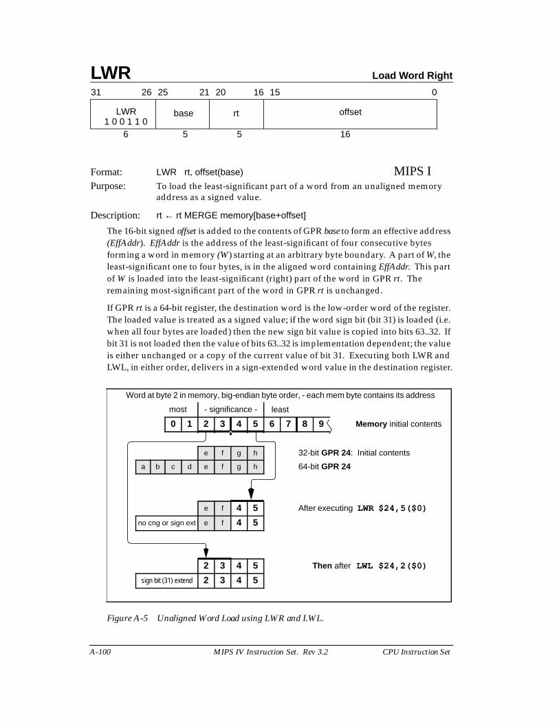
LWR Load Word Right
A-100 MIPS IV Instruction Set. Rev 3.2 CPU Instruction Set
Format: LWR rt, offset(base) MIPS IPurpose: To load the least-significant part of a word from an unaligned memory
address as a signed value.
Description: rt ← rt MERGE memory[base+offset]
The 16-bit signed offset is added to the contents of GPR base to form an effective address(EffAddr). EffAddr is the address of the least-significant of four consecutive bytesforming a word in memory (W) starting at an arbitrary byte boundary. A part of W, theleast-significant one to four bytes, is in the aligned word containing EffAddr. This partof W is loaded into the least-significant (right) part of the word in GPR rt. Theremaining most-significant part of the word in GPR rt is unchanged.
If GPR rt is a 64-bit register, the destination word is the low-order word of the register.The loaded value is treated as a signed value; if the word sign bit (bit 31) is loaded (i.e.when all four bytes are loaded) then the new sign bit value is copied into bits 63..32. Ifbit 31 is not loaded then the value of bits 63..32 is implementation dependent; the valueis either unchanged or a copy of the current value of bit 31. Executing both LWR andLWL, in either order, delivers in a sign-extended word value in the destination register.
Figure A-5 Unaligned Word Load using LWR and LWL.
31 2526 2021 1516 0
LWR base rt offset
6 5 5 161 0 0 1 1 0
Word at byte 2 in memory, big-endian byte order, - each mem byte contains its address
most - significance - least
0 1 2 3 4 5 6 7 8 9 Memory initial contents
e f g h 32-bit GPR 24: Initial contents
a b c d e f g h 64-bit GPR 24
e f 4 5 After executing LWR $24,5($0)
no cng or sign ext e f 4 5
2 3 4 5 Then after LWL $24,2($0)
sign bit (31) extend 2 3 4 5
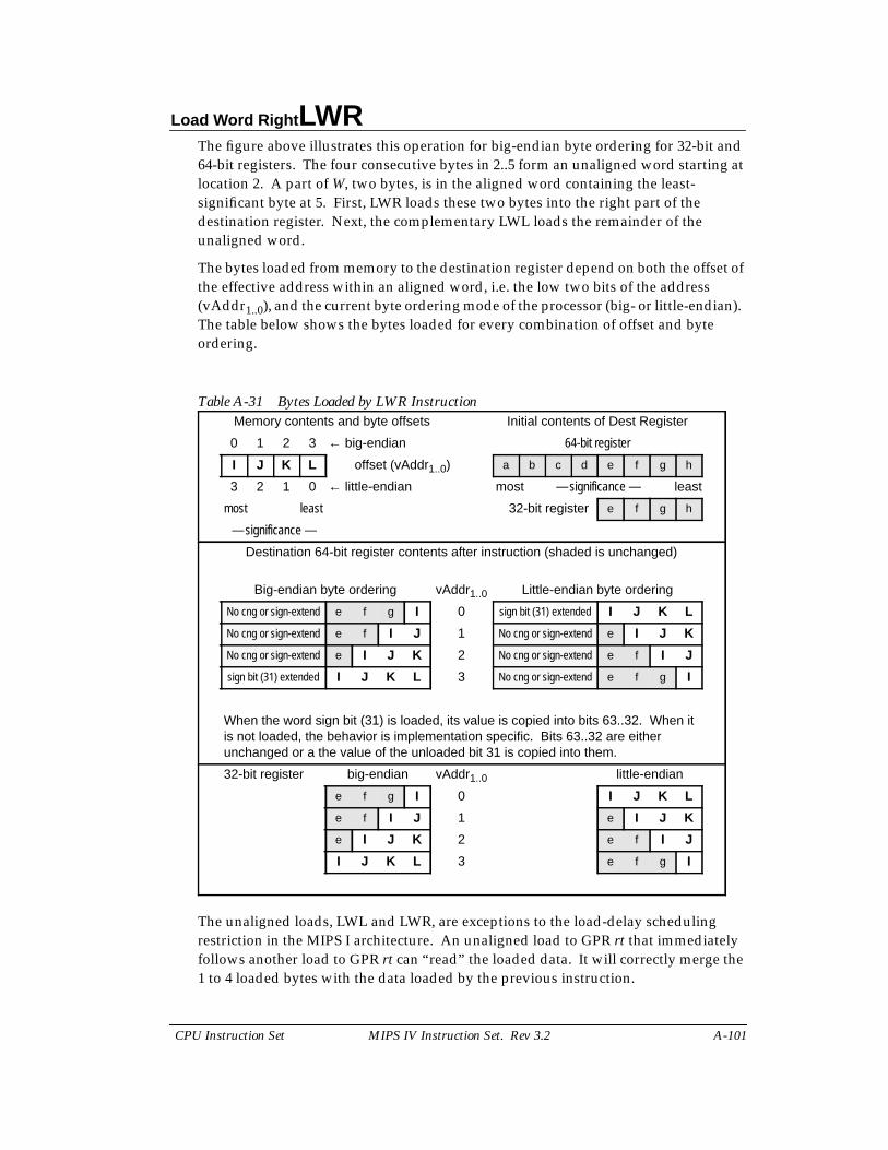
Load Word Right LWR
CPU Instruction Set MIPS IV Instruction Set. Rev 3.2 A-101
The figure above illustrates this operation for big-endian byte ordering for 32-bit and64-bit registers. The four consecutive bytes in 2..5 form an unaligned word starting atlocation 2. A part of W, two bytes, is in the aligned word containing the least-significant byte at 5. First, LWR loads these two bytes into the right part of thedestination register. Next, the complementary LWL loads the remainder of theunaligned word.
The bytes loaded from memory to the destination register depend on both the offset ofthe effective address within an aligned word, i.e. the low two bits of the address(vAddr1..0), and the current byte ordering mode of the processor (big- or little-endian).The table below shows the bytes loaded for every combination of offset and byteordering.
The unaligned loads, LWL and LWR, are exceptions to the load-delay schedulingrestriction in the MIPS I architecture. An unaligned load to GPR rt that immediatelyfollows another load to GPR rt can “read” the loaded data. It will correctly merge the1 to 4 loaded bytes with the data loaded by the previous instruction.
Table A-31 Bytes Loaded by LWR InstructionMemory contents and byte offsets Initial contents of Dest Register
0 1 2 3 ← big-endian 64-bit register
I J K L offset (vAddr1..0) a b c d e f g h
3 2 1 0 ← little-endian most — significance — least
most least 32-bit register e f g h
— significance —
Destination 64-bit register contents after instruction (shaded is unchanged)
Big-endian byte ordering vAddr1..0 Little-endian byte ordering
No cng or sign-extend e f g I 0 sign bit (31) extended I J K L
No cng or sign-extend e f I J 1 No cng or sign-extend e I J K
No cng or sign-extend e I J K 2 No cng or sign-extend e f I J
sign bit (31) extended I J K L 3 No cng or sign-extend e f g I
When the word sign bit (31) is loaded, its value is copied into bits 63..32. When itis not loaded, the behavior is implementation specific. Bits 63..32 are eitherunchanged or a the value of the unloaded bit 31 is copied into them.
32-bit register big-endian vAddr1..0 little-endian
e f g I 0 I J K L
e f I J 1 e I J K
e I J K 2 e f I J
I J K L 3 e f g I
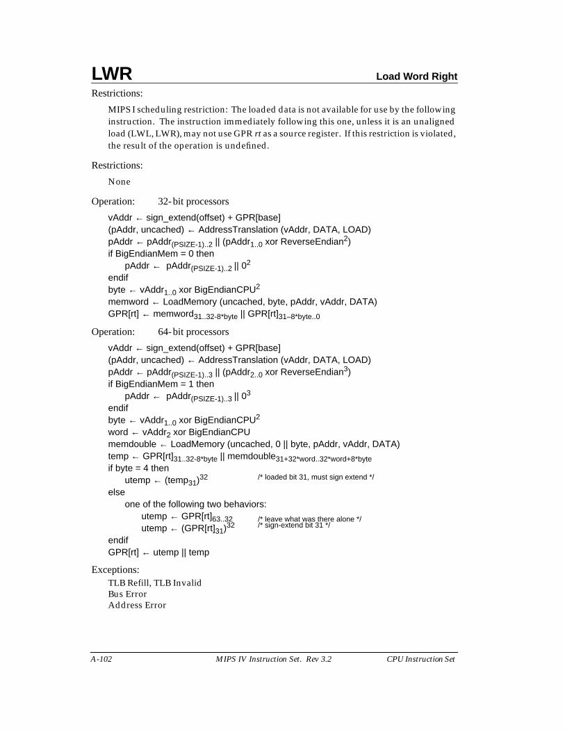
LWR Load Word Right
A-102 MIPS IV Instruction Set. Rev 3.2 CPU Instruction Set
Restrictions:
MIPS I scheduling restriction: The loaded data is not available for use by the followinginstruction. The instruction immediately following this one, unless it is an unalignedload (LWL, LWR), may not use GPR rt as a source register. If this restriction is violated,the result of the operation is undefined.
Restrictions:
None
Operation: 32-bit processors
vAddr ← sign_extend(offset) + GPR[base](pAddr, uncached) ← AddressTranslation (vAddr, DATA, LOAD)pAddr ← pAddr(PSIZE-1)..2 || (pAddr1..0 xor ReverseEndian2)if BigEndianMem = 0 then
pAddr ← pAddr(PSIZE-1)..2 || 02
endifbyte ← vAddr1..0 xor BigEndianCPU2
memword ← LoadMemory (uncached, byte, pAddr, vAddr, DATA)GPR[rt] ← memword31..32-8*byte || GPR[rt]31–8*byte..0
Operation: 64-bit processors
vAddr ← sign_extend(offset) + GPR[base](pAddr, uncached) ← AddressTranslation (vAddr, DATA, LOAD)pAddr ← pAddr(PSIZE-1)..3 || (pAddr2..0 xor ReverseEndian3)if BigEndianMem = 1 then
pAddr ← pAddr(PSIZE-1)..3 || 03
endifbyte ← vAddr1..0 xor BigEndianCPU2
word ← vAddr2 xor BigEndianCPUmemdouble ← LoadMemory (uncached, 0 || byte, pAddr, vAddr, DATA)temp ← GPR[rt]31..32-8*byte || memdouble31+32*word..32*word+8*byteif byte = 4 then
utemp ← (temp31)32 /* loaded bit 31, must sign extend */
elseone of the following two behaviors:
utemp ← GPR[rt]63..32 /* leave what was there alone */utemp ← (GPR[rt]31)32 /* sign-extend bit 31 */
endifGPR[rt] ← utemp || temp
Exceptions:TLB Refill, TLB InvalidBus ErrorAddress Error
Load Word Right LWR
CPU Instruction Set MIPS IV Instruction Set. Rev 3.2 A-103
Programming Notes:
The architecture provides no direct support for treating unaligned words as unsignedvalues, i.e. zeroing bits 63..32 of the destination register when bit 31 is loaded. See SLLor SLLV for a single-instruction method of propagating the word sign bit in a registerinto the upper half of a 64-bit register.
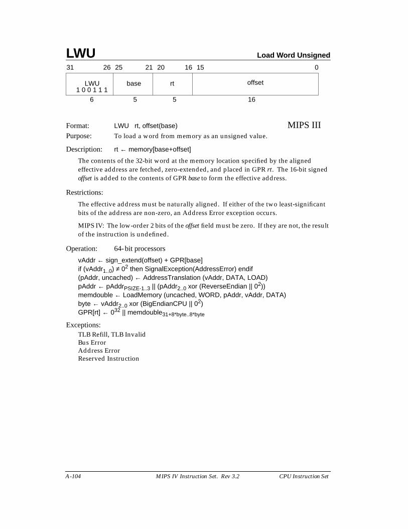
LWU Load Word Unsigned
A-104 MIPS IV Instruction Set. Rev 3.2 CPU Instruction Set
Format: LWU rt, offset(base) MIPS IIIPurpose: To load a word from memory as an unsigned value.
Description: rt ← memory[base+offset]
The contents of the 32-bit word at the memory location specified by the alignedeffective address are fetched, zero-extended, and placed in GPR rt. The 16-bit signedoffset is added to the contents of GPR base to form the effective address.
Restrictions:
The effective address must be naturally aligned. If either of the two least-significantbits of the address are non-zero, an Address Error exception occurs.
MIPS IV: The low-order 2 bits of the offset field must be zero. If they are not, the resultof the instruction is undefined.
Operation: 64-bit processors
vAddr ← sign_extend(offset) + GPR[base]if (vAddr1..0) ≠ 02 then SignalException(AddressError) endif(pAddr, uncached) ← AddressTranslation (vAddr, DATA, LOAD)pAddr ← pAddrPSIZE-1..3 || (pAddr2..0 xor (ReverseEndian || 02))memdouble ← LoadMemory (uncached, WORD, pAddr, vAddr, DATA)byte ← vAddr2..0 xor (BigEndianCPU || 02)GPR[rt] ← 032 || memdouble31+8*byte..8*byte
Exceptions:TLB Refill, TLB InvalidBus ErrorAddress ErrorReserved Instruction
31 2526 2021 1516 0
LWU base rt offset
6 5 5 161 0 0 1 1 1
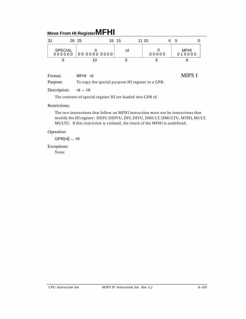
Move From HI Register MFHI
CPU Instruction Set MIPS IV Instruction Set. Rev 3.2 A-105
Format: MFHI rd MIPS IPurpose: To copy the special purpose HI register to a GPR.
Description: rd ← HI
The contents of special register HI are loaded into GPR rd.
Restrictions:
The two instructions that follow an MFHI instruction must not be instructions thatmodify the HI register: DDIV, DDIVU, DIV, DIVU, DMULT, DMULTU, MTHI, MULT,MULTU. If this restriction is violated, the result of the MFHI is undefined.
Operation:
GPR[rd] ← HI
Exceptions:None
0
31 2526 1516 0
rd
6 10 5
6 5
6
SPECIAL MFHI0
5
11 10
0 0 0 0 0 0 0 0 0 0 0 0 0 0 0 0 0 0 0 0 0 0 1 0 0 0 0
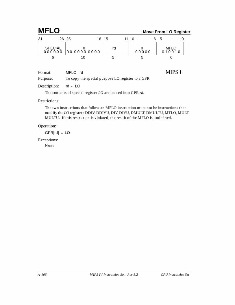
MFLO Move From LO Register
A-106 MIPS IV Instruction Set. Rev 3.2 CPU Instruction Set
Format: MFLO rd MIPS IPurpose: To copy the special purpose LO register to a GPR.
Description: rd ← LO
The contents of special register LO are loaded into GPR rd.
Restrictions:
The two instructions that follow an MFLO instruction must not be instructions thatmodify the LO register: DDIV, DDIVU, DIV, DIVU, DMULT, DMULTU, MTLO, MULT,MULTU. If this restriction is violated, the result of the MFLO is undefined.
Operation:
GPR[rd] ← LO
Exceptions:None
0
31 2526 1516 0
rd
6 10 5
6 5
6
SPECIAL MFLO0
5
11 10
0 0 0 0 0 0 0 0 0 0 0 0 0 0 0 0 0 0 0 0 0 0 1 0 0 1 0
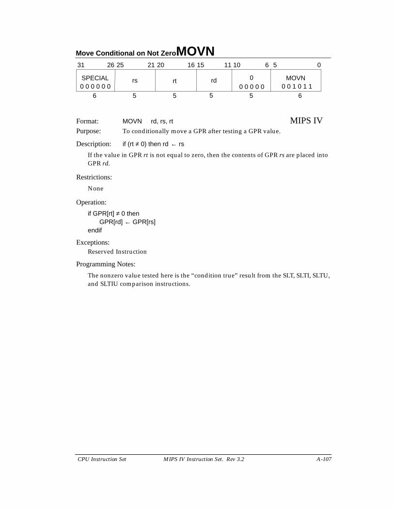
Move Conditional on Not Zero MOVN
CPU Instruction Set MIPS IV Instruction Set. Rev 3.2 A-107
Format: MOVN rd, rs, rt MIPS IVPurpose: To conditionally move a GPR after testing a GPR value.
Description: if (rt ≠ 0) then rd ← rs
If the value in GPR rt is not equal to zero, then the contents of GPR rs are placed intoGPR rd.
Restrictions:
None
Operation:
if GPR[rt] ≠ 0 thenGPR[rd] ← GPR[rs]
endif
Exceptions:Reserved Instruction
Programming Notes:
The nonzero value tested here is the “condition true” result from the SLT, SLTI, SLTU,and SLTIU comparison instructions.
31 2526 1516 0
6 5 5
6 5
6
SPECIAL
5
11 1021 20
5
0 MOVNrdrtrs0 0 0 0 0 0 0 0 0 0 0 0 0 1 0 1 1
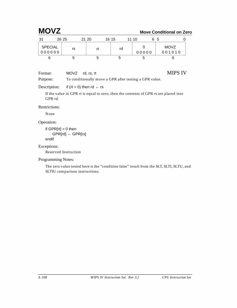
MOVZ Move Conditional on Zero
A-108 MIPS IV Instruction Set. Rev 3.2 CPU Instruction Set
Format: MOVZ rd, rs, rt MIPS IVPurpose: To conditionally move a GPR after testing a GPR value.
Description: if (rt = 0) then rd ← rs
If the value in GPR rt is equal to zero, then the contents of GPR rs are placed intoGPR rd.
Restrictions:
None
Operation:
if GPR[rt] = 0 thenGPR[rd] ← GPR[rs]
endif
Exceptions:Reserved Instruction
Programming Notes:
The zero value tested here is the “condition false” result from the SLT, SLTI, SLTU, andSLTIU comparison instructions.
31 2526 1516 0
6 5 5
6 5
6
SPECIAL
5
11 1021 20
5
0 MOVZrdrtrs0 0 0 0 0 0 0 0 0 0 0 0 0 1 0 1 0
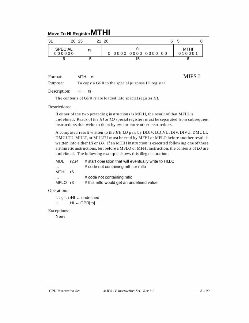
Move To HI Register MTHI
CPU Instruction Set MIPS IV Instruction Set. Rev 3.2 A-109
Format: MTHI rs MIPS IPurpose: To copy a GPR to the special purpose HI register.
Description: HI ← rs
The contents of GPR rs are loaded into special register HI.
Restrictions:
If either of the two preceding instructions is MFHI, the result of that MFHI isundefined. Reads of the HI or LO special registers must be separated from subsequentinstructions that write to them by two or more other instructions.
A computed result written to the HI/LO pair by DDIV, DDIVU, DIV, DIVU, DMULT,DMULTU, MULT, or MULTU must be read by MFHI or MFLO before another result iswritten into either HI or LO. If an MTHI instruction is executed following one of thesearithmetic instructions, but before a MFLO or MFHI instruction, the contents of LO areundefined. The following example shows this illegal situation:
MUL r2,r4 # start operation that will eventually write to HI,LO... # code not containing mfhi or mfloMTHI r6... # code not containing mfloMFLO r3 # this mflo would get an undefined value
Operation:
I - 2 :, I - 1 :HI ← undefinedI : HI ← GPR[rs]
Exceptions:None
31 2526 2021 0
rs
6 5
6 5
15 6
SPECIAL 0 MTHI0 0 0 0 0 0 0 0 0 0 0 0 0 0 0 0 0 0 0 0 0 0 1 0 0 0 1
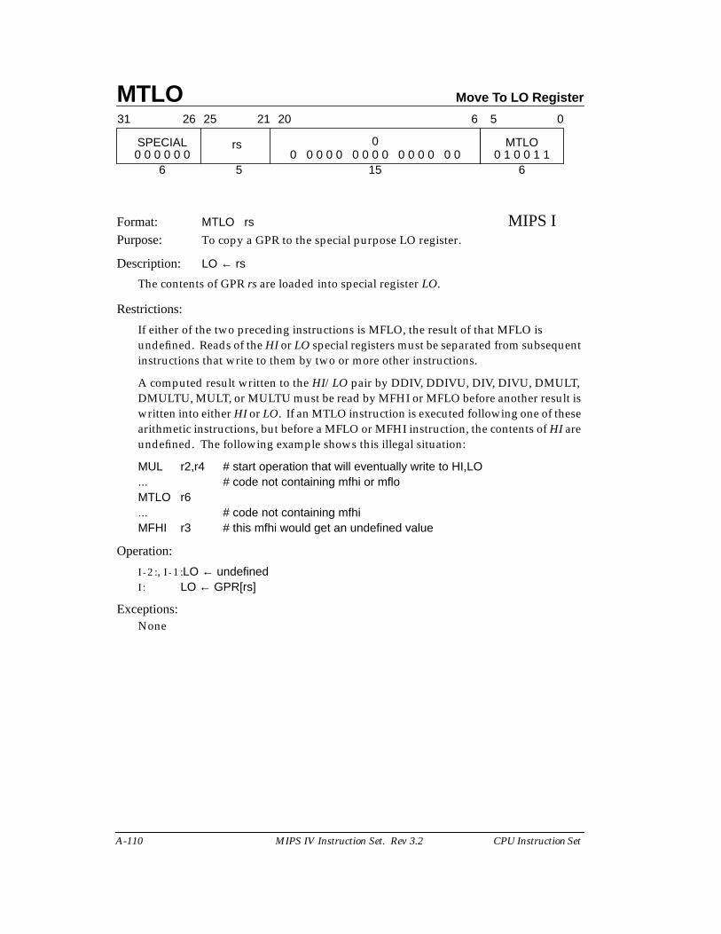
MTLO Move To LO Register
A-110 MIPS IV Instruction Set. Rev 3.2 CPU Instruction Set
Format: MTLO rs MIPS IPurpose: To copy a GPR to the special purpose LO register.
Description: LO ← rs
The contents of GPR rs are loaded into special register LO.
Restrictions:
If either of the two preceding instructions is MFLO, the result of that MFLO isundefined. Reads of the HI or LO special registers must be separated from subsequentinstructions that write to them by two or more other instructions.
A computed result written to the HI/LO pair by DDIV, DDIVU, DIV, DIVU, DMULT,DMULTU, MULT, or MULTU must be read by MFHI or MFLO before another result iswritten into either HI or LO. If an MTLO instruction is executed following one of thesearithmetic instructions, but before a MFLO or MFHI instruction, the contents of HI areundefined. The following example shows this illegal situation:
MUL r2,r4 # start operation that will eventually write to HI,LO... # code not containing mfhi or mfloMTLO r6... # code not containing mfhiMFHI r3 # this mfhi would get an undefined value
Operation:
I - 2 :, I - 1 :LO ← undefinedI : LO ← GPR[rs]
Exceptions:None
31 2526 2021 0
rs
6 5
6 5
15 6
SPECIAL 0 MTLO0 0 0 0 0 0 0 0 0 0 0 0 0 0 0 0 0 0 0 0 0 0 1 0 0 1 1
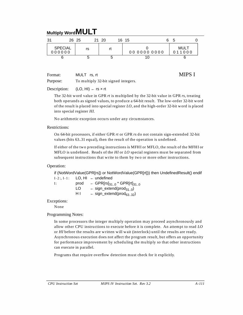
Multiply Word MULT
CPU Instruction Set MIPS IV Instruction Set. Rev 3.2 A-111
Format: MULT rs, rt MIPS IPurpose: To multiply 32-bit signed integers.
Description: (LO, HI) ← rs × rt
The 32-bit word value in GPR rt is multiplied by the 32-bit value in GPR rs, treatingboth operands as signed values, to produce a 64-bit result. The low-order 32-bit wordof the result is placed into special register LO, and the high-order 32-bit word is placedinto special register HI.
No arithmetic exception occurs under any circumstances.
Restrictions:
On 64-bit processors, if either GPR rt or GPR rs do not contain sign-extended 32-bitvalues (bits 63..31 equal), then the result of the operation is undefined.
If either of the two preceding instructions is MFHI or MFLO, the result of the MFHI orMFLO is undefined. Reads of the HI or LO special registers must be separated fromsubsequent instructions that write to them by two or more other instructions.
Operation:
if (NotWordValue(GPR[rs]) or NotWordValue(GPR[rt])) then UndefinedResult() endifI - 2 :, I - 1 : LO, HI ← undefinedI : prod ← GPR[rs]31..0 * GPR[rt]31..0
LO ← sign_extend(prod31..0)H I ← sign_extend(prod63..32)
Exceptions:None
Programming Notes:
In some processors the integer multiply operation may proceed asynchronously andallow other CPU instructions to execute before it is complete. An attempt to read LOor HI before the results are written will wait (interlock) until the results are ready.Asynchronous execution does not affect the program result, but offers an opportunityfor performance improvement by scheduling the multiply so that other instructionscan execute in parallel.
Programs that require overflow detection must check for it explicitly.
31 2526 2021 1516 0
rs rt
6 5 5
6 5
10 6
SPECIAL 0 MULT0 0 0 0 0 0 0 0 0 0 0 0 0 0 0 0 0 1 1 0 0 0
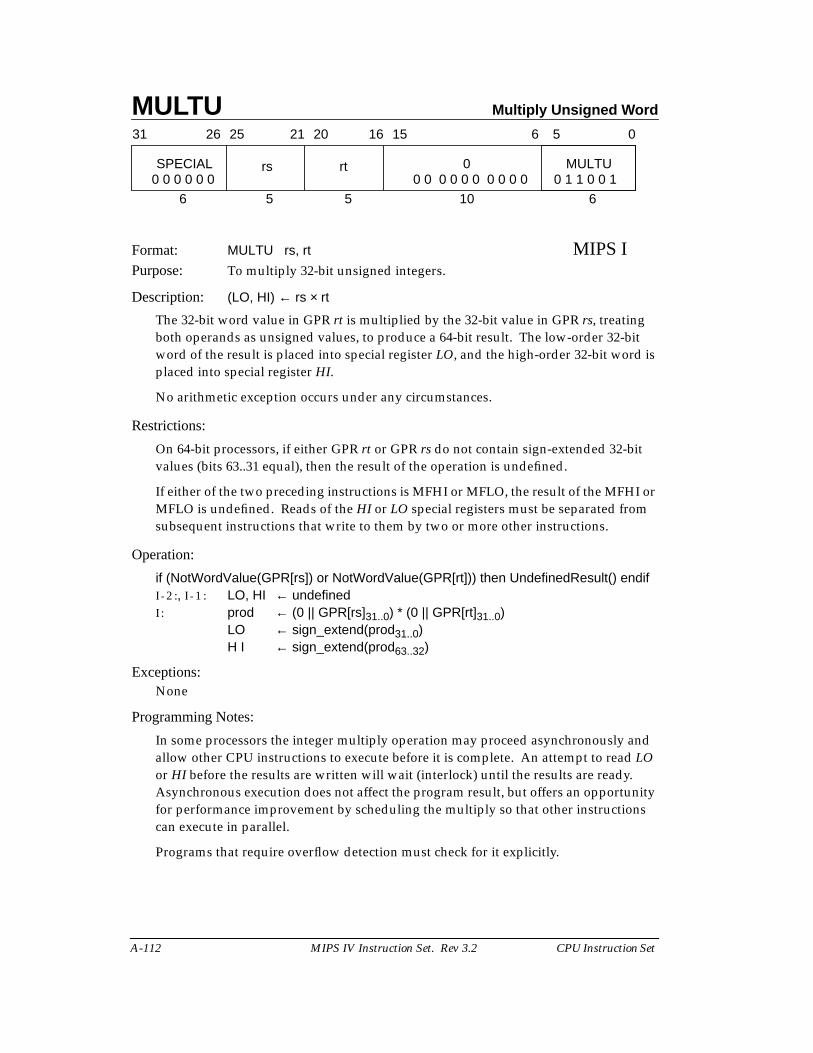
MULTU Multiply Unsigned Word
A-112 MIPS IV Instruction Set. Rev 3.2 CPU Instruction Set
Format: MULTU rs, rt MIPS IPurpose: To multiply 32-bit unsigned integers.
Description: (LO, HI) ← rs × rt
The 32-bit word value in GPR rt is multiplied by the 32-bit value in GPR rs, treatingboth operands as unsigned values, to produce a 64-bit result. The low-order 32-bitword of the result is placed into special register LO, and the high-order 32-bit word isplaced into special register HI.
No arithmetic exception occurs under any circumstances.
Restrictions:
On 64-bit processors, if either GPR rt or GPR rs do not contain sign-extended 32-bitvalues (bits 63..31 equal), then the result of the operation is undefined.
If either of the two preceding instructions is MFHI or MFLO, the result of the MFHI orMFLO is undefined. Reads of the HI or LO special registers must be separated fromsubsequent instructions that write to them by two or more other instructions.
Operation:
if (NotWordValue(GPR[rs]) or NotWordValue(GPR[rt])) then UndefinedResult() endifI - 2 :, I - 1 : LO, HI ← undefinedI : prod ← (0 || GPR[rs]31..0) * (0 || GPR[rt]31..0)
LO ← sign_extend(prod31..0)H I ← sign_extend(prod63..32)
Exceptions:None
Programming Notes:
In some processors the integer multiply operation may proceed asynchronously andallow other CPU instructions to execute before it is complete. An attempt to read LOor HI before the results are written will wait (interlock) until the results are ready.Asynchronous execution does not affect the program result, but offers an opportunityfor performance improvement by scheduling the multiply so that other instructionscan execute in parallel.
Programs that require overflow detection must check for it explicitly.
31 2526 2021 1516 0
rs rt
6 5 5
6 5
10 6
SPECIAL 0 MULTU0 0 0 0 0 0 0 0 0 0 0 0 0 0 0 0 0 1 1 0 0 1
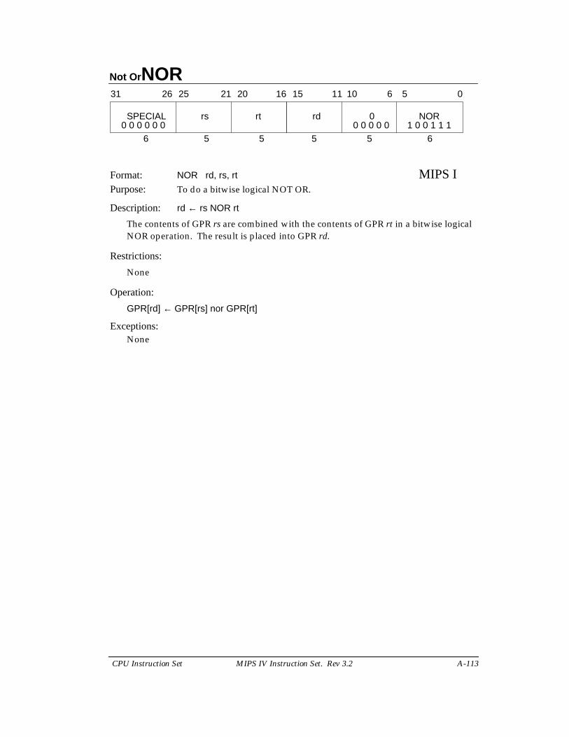
Not OrNOR
CPU Instruction Set MIPS IV Instruction Set. Rev 3.2 A-113
Format: NOR rd, rs, rt MIPS IPurpose: To do a bitwise logical NOT OR.
Description: rd ← rs NOR rt
The contents of GPR rs are combined with the contents of GPR rt in a bitwise logicalNOR operation. The result is placed into GPR rd.
Restrictions:
None
Operation:
GPR[rd] ← GPR[rs] nor GPR[rt]
Exceptions:None
31 2526 2021 1516
SPECIAL rs rt
6 5 5
rd 0 NOR
5 5 6
11 10 6 5 0
0 0 0 0 0 0 0 0 0 0 0 1 0 0 1 1 1
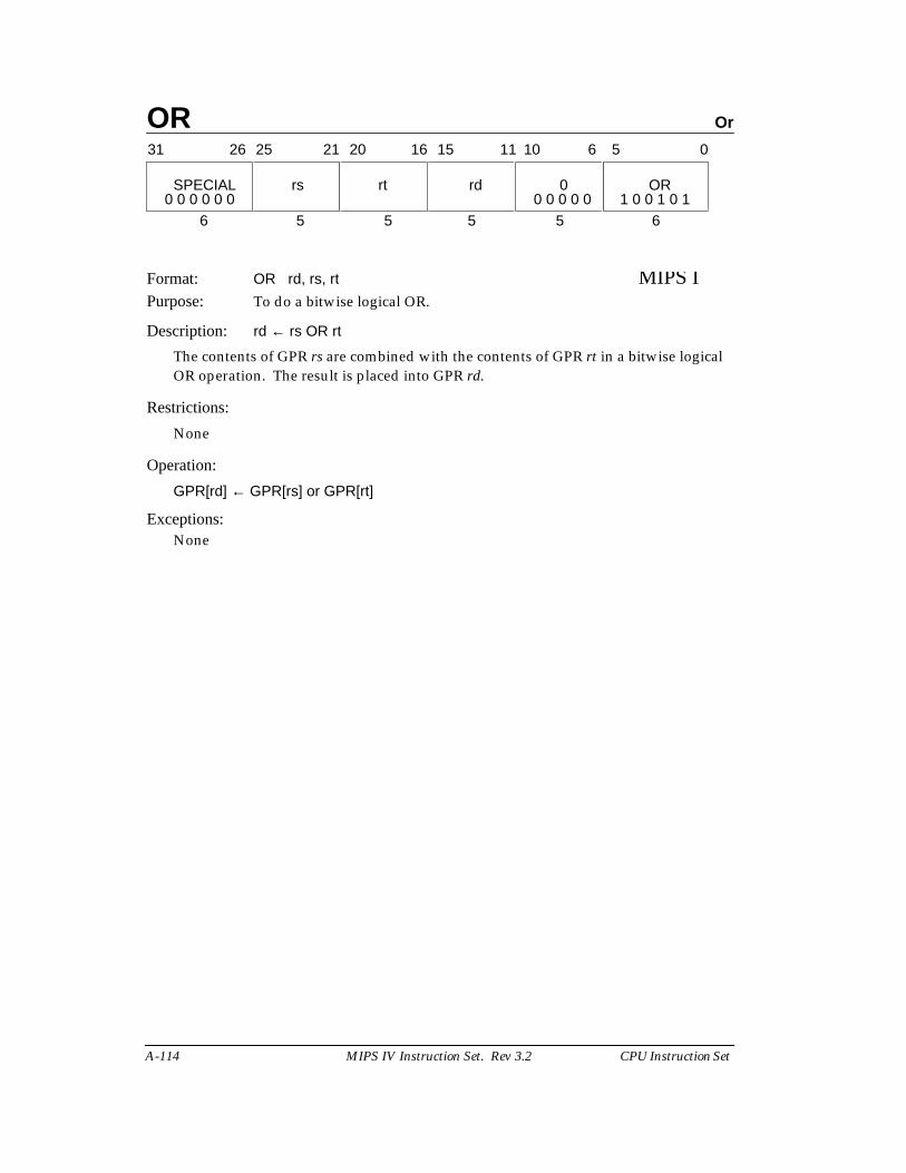
OR Or
A-114 MIPS IV Instruction Set. Rev 3.2 CPU Instruction Set
Format: OR rd, rs, rt MIPS IPurpose: To do a bitwise logical OR.
Description: rd ← rs OR rt
The contents of GPR rs are combined with the contents of GPR rt in a bitwise logicalOR operation. The result is placed into GPR rd.
Restrictions:
None
Operation:
GPR[rd] ← GPR[rs] or GPR[rt]
Exceptions:None
31 2526 2021 1516
SPECIAL rs rt
6 5 5
rd 0 OR
5 5 6
11 10 6 5 0
0 0 0 0 0 0 0 0 0 0 0 1 0 0 1 0 1
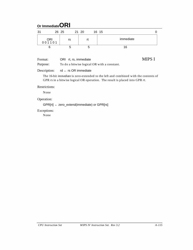
Or Immediate ORI
CPU Instruction Set MIPS IV Instruction Set. Rev 3.2 A-115
Format: ORI rt, rs, immediate MIPS IPurpose: To do a bitwise logical OR with a constant.
Description: rd ← rs OR immediate
The 16-bit immediate is zero-extended to the left and combined with the contents ofGPR rs in a bitwise logical OR operation. The result is placed into GPR rt.
Restrictions:
None
Operation:
GPR[rt] ← zero_extend(immediate) or GPR[rs]
Exceptions:None
31 2526 2021 1516 0
ORI rs rt immediate
6 5 5 160 0 1 1 0 1
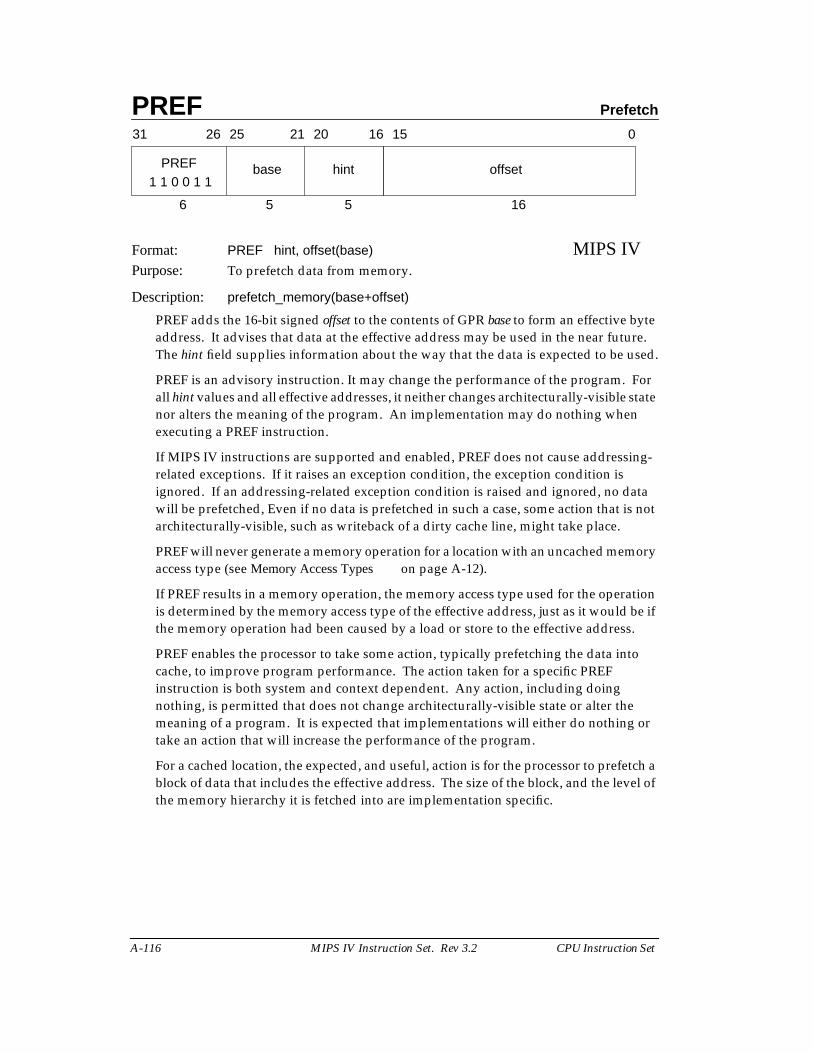
PREF Prefetch
A-116 MIPS IV Instruction Set. Rev 3.2 CPU Instruction Set
Format: PREF hint, offset(base) MIPS IVPurpose: To prefetch data from memory.
Description: prefetch_memory(base+offset)
PREF adds the 16-bit signed offset to the contents of GPR base to form an effective byteaddress. It advises that data at the effective address may be used in the near future.The hint field supplies information about the way that the data is expected to be used.
PREF is an advisory instruction. It may change the performance of the program. Forall hint values and all effective addresses, it neither changes architecturally-visible statenor alters the meaning of the program. An implementation may do nothing whenexecuting a PREF instruction.
If MIPS IV instructions are supported and enabled, PREF does not cause addressing-related exceptions. If it raises an exception condition, the exception condition isignored. If an addressing-related exception condition is raised and ignored, no datawill be prefetched, Even if no data is prefetched in such a case, some action that is notarchitecturally-visible, such as writeback of a dirty cache line, might take place.
PREF will never generate a memory operation for a location with an uncached memoryaccess type (see Memory Access Types on page A-12).
If PREF results in a memory operation, the memory access type used for the operationis determined by the memory access type of the effective address, just as it would be ifthe memory operation had been caused by a load or store to the effective address.
PREF enables the processor to take some action, typically prefetching the data intocache, to improve program performance. The action taken for a specific PREFinstruction is both system and context dependent. Any action, including doingnothing, is permitted that does not change architecturally-visible state or alter themeaning of a program. It is expected that implementations will either do nothing ortake an action that will increase the performance of the program.
For a cached location, the expected, and useful, action is for the processor to prefetch ablock of data that includes the effective address. The size of the block, and the level ofthe memory hierarchy it is fetched into are implementation specific.
31 2526 2021 1516
base hint
6 5 5
offset
16
0
1 1 0 0 1 1PREF
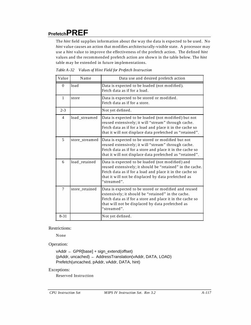
Prefetch PREF
CPU Instruction Set MIPS IV Instruction Set. Rev 3.2 A-117
The hint field supplies information about the way the data is expected to be used. Nohint value causes an action that modifies architecturally-visible state. A processor mayuse a hint value to improve the effectiveness of the prefetch action. The defined hintvalues and the recommended prefetch action are shown in the table below. The hinttable may be extended in future implementations.
Restrictions:
None
Operation:
vAddr ← GPR[base] + sign_extend(offset)(pAddr, uncached) ← AddressTranslation(vAddr, DATA, LOAD)Prefetch(uncached, pAddr, vAddr, DATA, hint)
Exceptions:Reserved Instruction
Table A-32 Values of Hint Field for Prefetch Instruction
Value Name Data use and desired prefetch action
0 load Data is expected to be loaded (not modified).Fetch data as if for a load.
1 store Data is expected to be stored or modified.Fetch data as if for a store.
2-3 Not yet defined.
4 load_streamed Data is expected to be loaded (not modified) but notreused extensively; it will “stream” through cache.Fetch data as if for a load and place it in the cache sothat it will not displace data prefetched as “retained”.
5 store_streamed Data is expected to be stored or modified but notreused extensively; it will “stream” through cache.Fetch data as if for a store and place it in the cache sothat it will not displace data prefetched as “retained”.
6 load_retained Data is expected to be loaded (not modified) andreused extensively; it should be “retained” in the cache.Fetch data as if for a load and place it in the cache sothat it will not be displaced by data prefetched as“streamed”.
7 store_retained Data is expected to be stored or modified and reusedextensively; it should be “retained” in the cache.Fetch data as if for a store and place it in the cache sothat will not be displaced by data prefetched as“streamed”.
8-31 Not yet defined.
PREF Prefetch
A-118 MIPS IV Instruction Set. Rev 3.2 CPU Instruction Set
Programming Notes:
Prefetch can not prefetch data from a mapped location unless the translation for thatlocation is present in the TLB. Locations in memory pages that have not been accessedrecently may not have translations in the TLB, so prefetch may not be effective for suchlocations.
Prefetch does not cause addressing exceptions. It will not cause an exception toprefetch using an address pointer value before the validity of a pointer is determined.
Implementation Notes:
It is recommended that a reserved hint field value either cause a default prefetch actionthat is expected to be useful for most cases of data use, such as the “load” hint, or causethe instruction to be treated as a NOP.
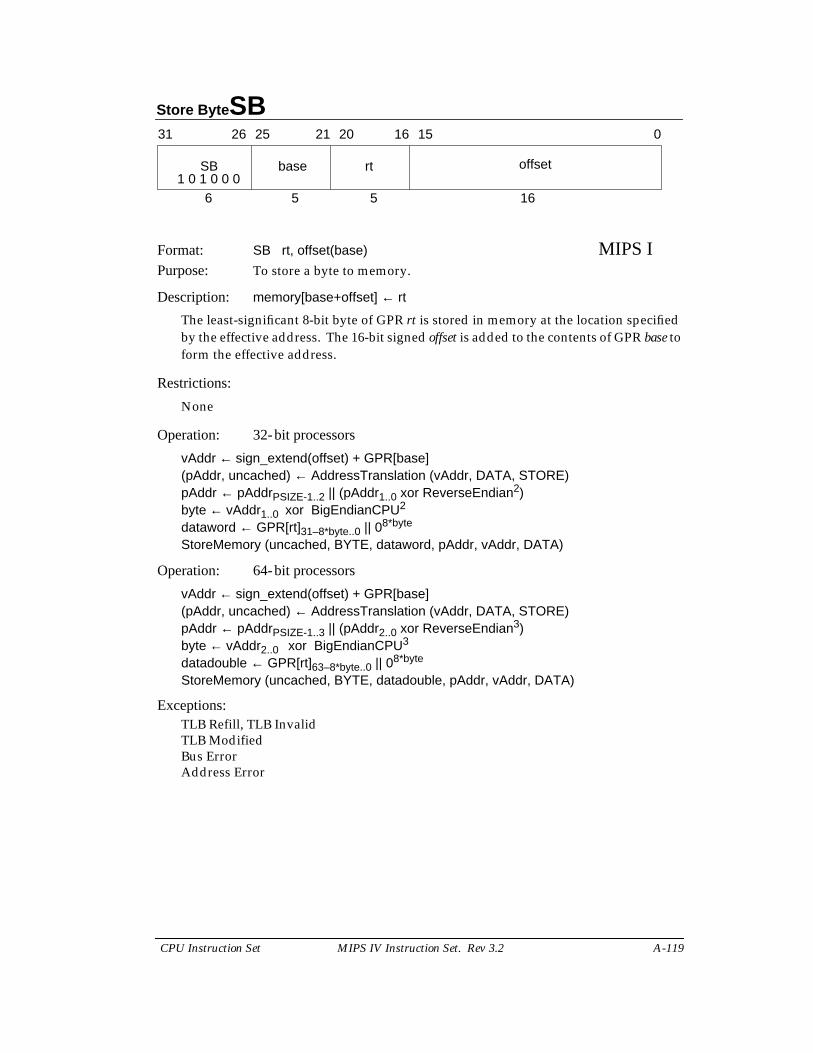
Store Byte SB
CPU Instruction Set MIPS IV Instruction Set. Rev 3.2 A-119
Format: SB rt, offset(base) MIPS IPurpose: To store a byte to memory.
Description: memory[base+offset] ← rt
The least-significant 8-bit byte of GPR rt is stored in memory at the location specifiedby the effective address. The 16-bit signed offset is added to the contents of GPR base toform the effective address.
Restrictions:
None
Operation: 32-bit processors
vAddr ← sign_extend(offset) + GPR[base](pAddr, uncached) ← AddressTranslation (vAddr, DATA, STORE)pAddr ← pAddrPSIZE-1..2 || (pAddr1..0 xor ReverseEndian2)byte ← vAddr1..0 xor BigEndianCPU2
dataword ← GPR[rt]31–8*byte..0 || 08*byte
StoreMemory (uncached, BYTE, dataword, pAddr, vAddr, DATA)
Operation: 64-bit processors
vAddr ← sign_extend(offset) + GPR[base](pAddr, uncached) ← AddressTranslation (vAddr, DATA, STORE)pAddr ← pAddrPSIZE-1..3 || (pAddr2..0 xor ReverseEndian3)byte ← vAddr2..0 xor BigEndianCPU3
datadouble ← GPR[rt]63–8*byte..0 || 08*byte
StoreMemory (uncached, BYTE, datadouble, pAddr, vAddr, DATA)
Exceptions:TLB Refill, TLB InvalidTLB ModifiedBus ErrorAddress Error
31 2526 2021 1516 0
SB base rt offset
6 5 5 161 0 1 0 0 0
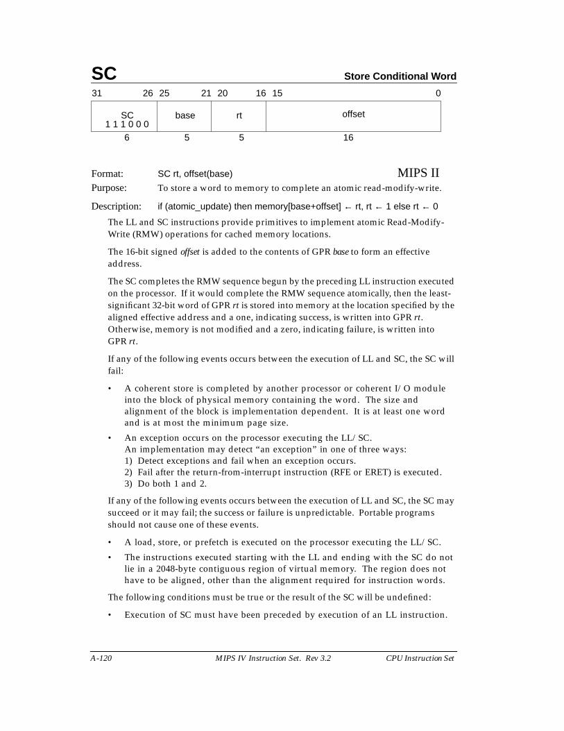
SC Store Conditional Word
A-120 MIPS IV Instruction Set. Rev 3.2 CPU Instruction Set
Format: SC rt, offset(base) MIPS IIPurpose: To store a word to memory to complete an atomic read-modify-write.
Description: if (atomic_update) then memory[base+offset] ← rt, rt ← 1 else rt ← 0
The LL and SC instructions provide primitives to implement atomic Read-Modify-Write (RMW) operations for cached memory locations.
The 16-bit signed offset is added to the contents of GPR base to form an effectiveaddress.
The SC completes the RMW sequence begun by the preceding LL instruction executedon the processor. If it would complete the RMW sequence atomically, then the least-significant 32-bit word of GPR rt is stored into memory at the location specified by thealigned effective address and a one, indicating success, is written into GPR rt.Otherwise, memory is not modified and a zero, indicating failure, is written intoGPR rt.
If any of the following events occurs between the execution of LL and SC, the SC willfail:
• A coherent store is completed by another processor or coherent I/O moduleinto the block of physical memory containing the word. The size andalignment of the block is implementation dependent. It is at least one wordand is at most the minimum page size.
• An exception occurs on the processor executing the LL/SC.An implementation may detect “an exception” in one of three ways:1) Detect exceptions and fail when an exception occurs.2) Fail after the return-from-interrupt instruction (RFE or ERET) is executed.3) Do both 1 and 2.
If any of the following events occurs between the execution of LL and SC, the SC maysucceed or it may fail; the success or failure is unpredictable. Portable programsshould not cause one of these events.
• A load, store, or prefetch is executed on the processor executing the LL/SC.
• The instructions executed starting with the LL and ending with the SC do notlie in a 2048-byte contiguous region of virtual memory. The region does nothave to be aligned, other than the alignment required for instruction words.
The following conditions must be true or the result of the SC will be undefined:
• Execution of SC must have been preceded by execution of an LL instruction.
31 2526 2021 1516 0
SC base rt offset
6 5 5 161 1 1 0 0 0
Store Conditional Word SC
CPU Instruction Set MIPS IV Instruction Set. Rev 3.2 A-121
• A RMW sequence executed without intervening exceptions must use the sameaddress in the LL and SC. The address is the same if the virtual address,physical address, and cache-coherence algorithm are identical.
Atomic RMW is provided only for cached memory locations. The extent to which thedetection of atomicity operates correctly depends on the system implementation andthe memory access type used for the location. See Memory Access Types on pageA-12.
MP atomicity : To provide atomic RMW among multiple processors, all accesses tothe location must be made with a memory access type of cached coherent.
Uniprocessor atomicity : To provide atomic RMW on a single processor, all accessesto the location must be made with memory access type of either cached noncoherentor cached coherent. All accesses must be to one or the other access type, they may notbe mixed.
I/O System : To provide atomic RMW with a coherent I/O system, all accesses to thelocation must be made with a memory access type of cached coherent. If the I/Osystem does not use coherent memory operations, then atomic RMW cannot beprovided with respect to the I/O reads and writes.
The definition above applies to user-mode operation on all MIPS processors thatsupport the MIPS II architecture. There may be other implementation-specific events,such as privileged CP0 instructions, that will cause an SC instruction to fail in somecases. System programmers using LL/SC should consult implementation-specificdocumentation.
Restrictions:
The addressed location must have a memory access type of cached noncoherent orcached coherent; if it does not, the result is undefined (see Memory Access Types onpage A-12).
The effective address must be naturally aligned. If either of the two least-significantbits of the address are non-zero, an Address Error exception occurs.
MIPS IV: The low-order 2 bits of the offset field must be zero. If they are not, the resultof the instruction is undefined.
Operation: 32-bit processors
vAddr ← sign_extend(offset) + GPR[base]if (vAddr1..0) ≠ 02 then SignalException(AddressError) endif(pAddr, uncached) ← AddressTranslation (vAddr, DATA, STORE)dataword ← GPR[rt]if LLbit then
StoreMemory (uncached, WORD, dataword, pAddr, vAddr, DATA)endifGPR[rt] ← 031 || LLbit
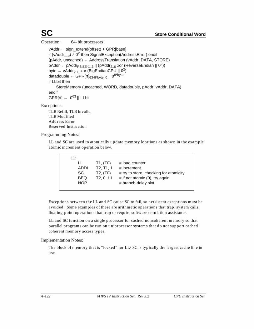
SC Store Conditional Word
A-122 MIPS IV Instruction Set. Rev 3.2 CPU Instruction Set
Operation: 64-bit processors
vAddr ← sign_extend(offset) + GPR[base]if (vAddr1..0) ≠ 02 then SignalException(AddressError) endif(pAddr, uncached) ← AddressTranslation (vAddr, DATA, STORE)pAddr ← pAddrPSIZE-1..3 || (pAddr2..0 xor (ReverseEndian || 02))byte ← vAddr2..0 xor (BigEndianCPU || 02)datadouble ← GPR[rt]63-8*byte..0 || 08*byte
if LLbit thenStoreMemory (uncached, WORD, datadouble, pAddr, vAddr, DATA)
endifGPR[rt] ← 063 || LLbit
Exceptions:TLB Refill, TLB InvalidTLB ModifiedAddress ErrorReserved Instruction
Programming Notes:
LL and SC are used to atomically update memory locations as shown in the exampleatomic increment operation below.
Exceptions between the LL and SC cause SC to fail, so persistent exceptions must beavoided. Some examples of these are arithmetic operations that trap, system calls,floating-point operations that trap or require software emulation assistance.
LL and SC function on a single processor for cached noncoherent memory so thatparallel programs can be run on uniprocessor systems that do not support cachedcoherent memory access types.
Implementation Notes:
The block of memory that is “locked” for LL/SC is typically the largest cache line inuse.
L1:LL T1, (T0) # load counterADDI T2, T1, 1 # incrementSC T2, (T0) # try to store, checking for atomicityBEQ T2, 0, L1 # if not atomic (0), try againNOP # branch-delay slot
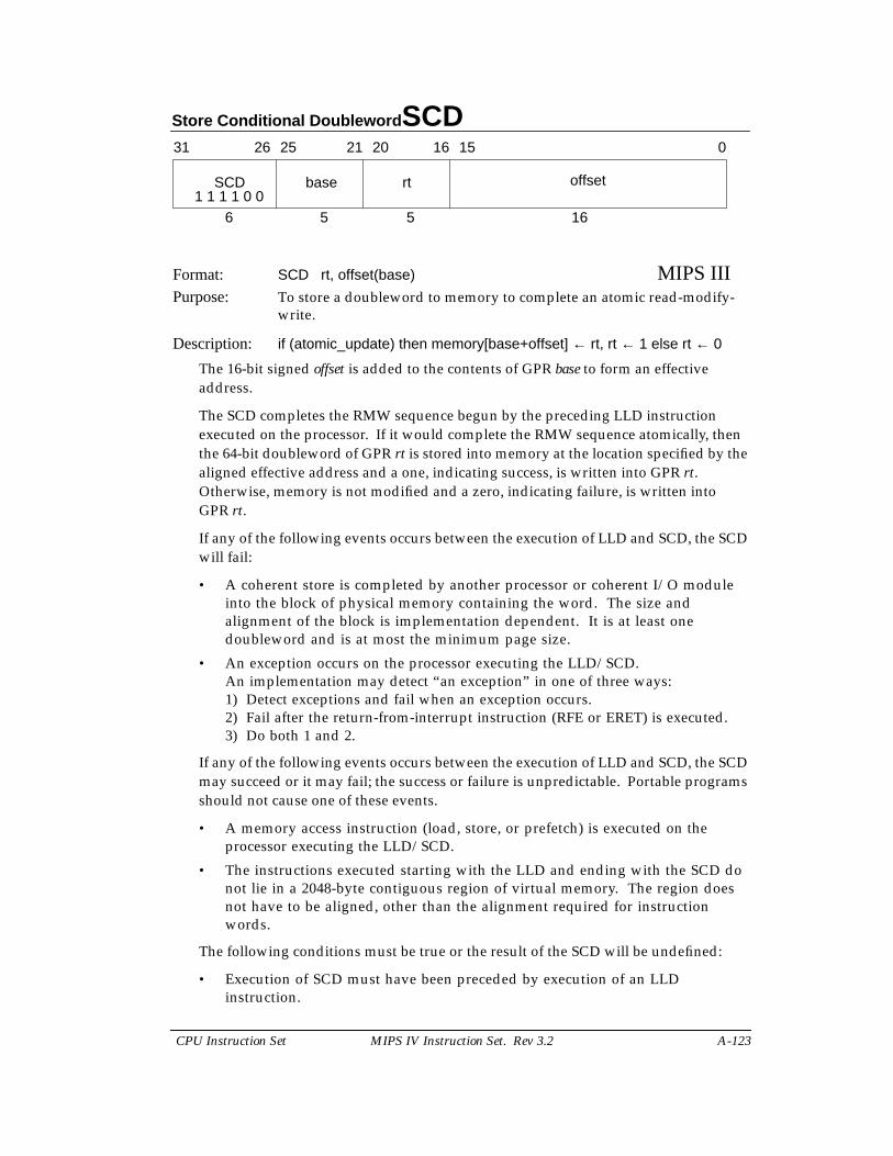
Store Conditional Doubleword SCD
CPU Instruction Set MIPS IV Instruction Set. Rev 3.2 A-123
Format: SCD rt, offset(base) MIPS IIIPurpose: To store a doubleword to memory to complete an atomic read-modify-
write.
Description: if (atomic_update) then memory[base+offset] ← rt, rt ← 1 else rt ← 0
The 16-bit signed offset is added to the contents of GPR base to form an effectiveaddress.
The SCD completes the RMW sequence begun by the preceding LLD instructionexecuted on the processor. If it would complete the RMW sequence atomically, thenthe 64-bit doubleword of GPR rt is stored into memory at the location specified by thealigned effective address and a one, indicating success, is written into GPR rt.Otherwise, memory is not modified and a zero, indicating failure, is written intoGPR rt.
If any of the following events occurs between the execution of LLD and SCD, the SCDwill fail:
• A coherent store is completed by another processor or coherent I/O moduleinto the block of physical memory containing the word. The size andalignment of the block is implementation dependent. It is at least onedoubleword and is at most the minimum page size.
• An exception occurs on the processor executing the LLD/SCD.An implementation may detect “an exception” in one of three ways:1) Detect exceptions and fail when an exception occurs.2) Fail after the return-from-interrupt instruction (RFE or ERET) is executed.3) Do both 1 and 2.
If any of the following events occurs between the execution of LLD and SCD, the SCDmay succeed or it may fail; the success or failure is unpredictable. Portable programsshould not cause one of these events.
• A memory access instruction (load, store, or prefetch) is executed on theprocessor executing the LLD/SCD.
• The instructions executed starting with the LLD and ending with the SCD donot lie in a 2048-byte contiguous region of virtual memory. The region doesnot have to be aligned, other than the alignment required for instructionwords.
The following conditions must be true or the result of the SCD will be undefined:
• Execution of SCD must have been preceded by execution of an LLDinstruction.
31 2526 2021 1516 0
SCD base rt offset
6 5 5 161 1 1 1 0 0
SCD Store Conditional Doubleword
A-124 MIPS IV Instruction Set. Rev 3.2 CPU Instruction Set
• A RMW sequence executed without intervening exceptions must use the sameaddress in the LLD and SCD. The address is the same if the virtual address,physical address, and cache-coherence algorithm are identical.
Atomic RMW is provided only for memory locations with cached noncoherent orcached coherent memory access types. The extent to which the detection of atomicityoperates correctly depends on the system implementation and the memory access typeused for the location. See Memory Access Types on page A-12.
MP atomicity : To provide atomic RMW among multiple processors, all accesses tothe location must be made with a memory access type of cached coherent.
Uniprocessor atomicity : To provide atomic RMW on a single processor, all accessesto the location must be made with memory access type of either cached noncoherentor cached coherent. All accesses must be to one or the other access type, they may notbe mixed.
I/O System : To provide atomic RMW with a coherent I/O system, all accesses to thelocation must be made with a memory access type of cached coherent. If the I/Osystem does not use coherent memory operations, then atomic RMW cannot beprovided with respect to the I/O reads and writes.
The defemination above applies to user-mode operation on all MIPS processors thatsupport the MIPS III architecture. There may be other implementation-specific events,such as privileged CP0 instructions, that will cause an SCD instruction to fail in somecases. System programmers using LLD/SCD should consult implementation-specificdocumentation.
Restrictions:
The addressed location must have a memory access type of cached noncoherent orcached coherent; if it does not, the result is undefined (see Memory Access Types onpage A-12The 64-bit doubleword of register rt is conditionally stored in memory at thelocation specified by the aligned effective address. The 16-bit signed offset is added tothe contents of GPR base to form the effective address.
The effective address must be naturally aligned. If any of the three least-significant bitsof the address are non-zero, an Address Error exception occurs.
MIPS IV: The low-order 3 bits of the offset field must be zero. If they are not, the resultof the instruction is undefined.
Operation: 64-bit processors
vAddr ← sign_extend(offset) + GPR[base]if (vAddr2..0) ≠ 03 then SignalException(AddressError) endif(pAddr, uncached) ← AddressTranslation (vAddr, DATA, STORE)datadouble ← GPR[rt]if LLbit then
StoreMemory (uncached, DOUBLEWORD, datadouble, pAddr, vAddr, DATA)endifGPR[rt] ← 063 || LLbit
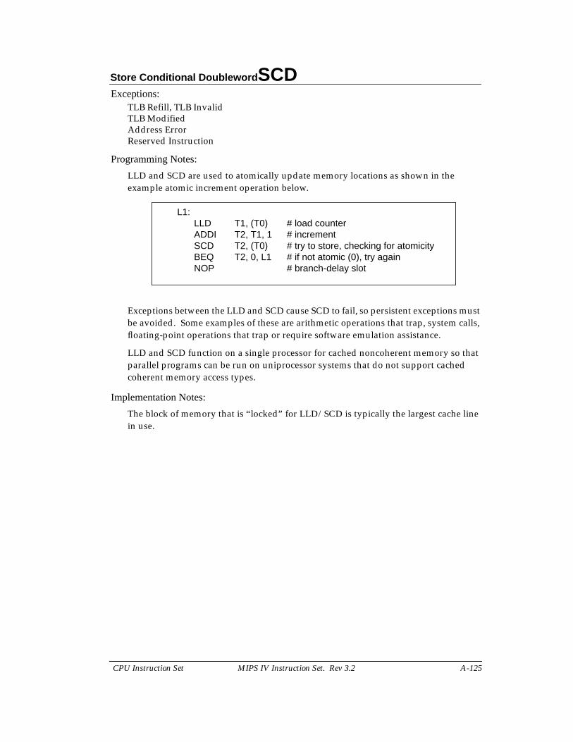
Store Conditional Doubleword SCD
CPU Instruction Set MIPS IV Instruction Set. Rev 3.2 A-125
Exceptions:TLB Refill, TLB InvalidTLB ModifiedAddress ErrorReserved Instruction
Programming Notes:
LLD and SCD are used to atomically update memory locations as shown in theexample atomic increment operation below.
Exceptions between the LLD and SCD cause SCD to fail, so persistent exceptions mustbe avoided. Some examples of these are arithmetic operations that trap, system calls,floating-point operations that trap or require software emulation assistance.
LLD and SCD function on a single processor for cached noncoherent memory so thatparallel programs can be run on uniprocessor systems that do not support cachedcoherent memory access types.
Implementation Notes:
The block of memory that is “locked” for LLD/SCD is typically the largest cache linein use.
L1:LLD T1, (T0) # load counterADDI T2, T1, 1 # incrementSCD T2, (T0) # try to store, checking for atomicityBEQ T2, 0, L1 # if not atomic (0), try againNOP # branch-delay slot
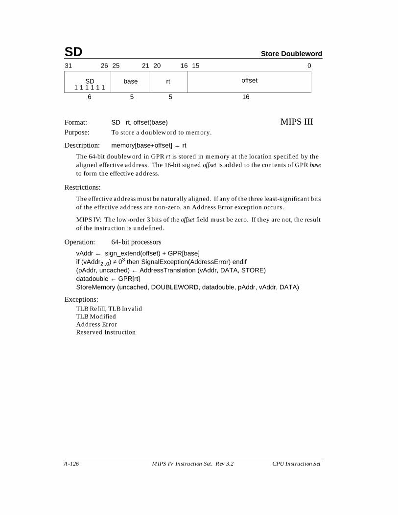
SD Store Doubleword
A-126 MIPS IV Instruction Set. Rev 3.2 CPU Instruction Set
Format: SD rt, offset(base) MIPS IIIPurpose: To store a doubleword to memory.
Description: memory[base+offset] ← rt
The 64-bit doubleword in GPR rt is stored in memory at the location specified by thealigned effective address. The 16-bit signed offset is added to the contents of GPR baseto form the effective address.
Restrictions:
The effective address must be naturally aligned. If any of the three least-significant bitsof the effective address are non-zero, an Address Error exception occurs.
MIPS IV: The low-order 3 bits of the offset field must be zero. If they are not, the resultof the instruction is undefined.
Operation: 64-bit processors
vAddr ← sign_extend(offset) + GPR[base]if (vAddr2..0) ≠ 03 then SignalException(AddressError) endif(pAddr, uncached) ← AddressTranslation (vAddr, DATA, STORE)datadouble ← GPR[rt]StoreMemory (uncached, DOUBLEWORD, datadouble, pAddr, vAddr, DATA)
Exceptions:TLB Refill, TLB InvalidTLB ModifiedAddress ErrorReserved Instruction
31 2526 2021 1516 0
SD base rt offset
6 5 5 161 1 1 1 1 1
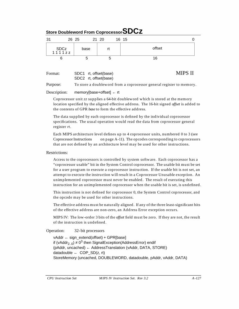
Store Doubleword From Coprocessor SDCz
CPU Instruction Set MIPS IV Instruction Set. Rev 3.2 A-127
Format: SDC1 rt, offset(base) MIPS IISDC2 rt, offset(base)
Purpose: To store a doubleword from a coprocessor general register to memory.
Description: memory[base+offset] ← rt
Coprocessor unit zz supplies a 64-bit doubleword which is stored at the memorylocation specified by the aligned effective address. The 16-bit signed offset is added tothe contents of GPR base to form the effective address.
The data supplied by each coprocessor is defined by the individual coprocessorspecifications. The usual operation would read the data from coprocessor generalregister rt.
Each MIPS architecture level defines up to 4 coprocessor units, numbered 0 to 3 (seeCoprocessor Instructions on page A-11). The opcodes corresponding to coprocessorsthat are not defined by an architecture level may be used for other instructions.
Restrictions:
Access to the coprocessors is controlled by system software. Each coprocessor has a“coprocessor usable” bit in the System Control coprocessor. The usable bit must be setfor a user program to execute a coprocessor instruction. If the usable bit is not set, anattempt to execute the instruction will result in a Coprocessor Unusable exception. Anunimplemented coprocessor must never be enabled. The result of executing thisinstruction for an unimplemented coprocessor when the usable bit is set, is undefined.
This instruction is not defined for coprocessor 0, the System Control coprocessor, andthe opcode may be used for other instructions.
The effective address must be naturally aligned. If any of the three least-significant bitsof the effective address are non-zero, an Address Error exception occurs.
MIPS IV: The low-order 3 bits of the offset field must be zero. If they are not, the resultof the instruction is undefined.
Operation: 32-bit processors
vAddr ← sign_extend(offset) + GPR[base]if (vAddr2..0) ≠ 03 then SignalException(AddressError) endif(pAddr, uncached) ← AddressTranslation (vAddr, DATA, STORE)datadouble ← COP_SD(z, rt)StoreMemory (uncached, DOUBLEWORD, datadouble, pAddr, vAddr, DATA)
31 2526 2021 1516 0
SDCz base rt offset
6 5 5 161 1 1 1 z z
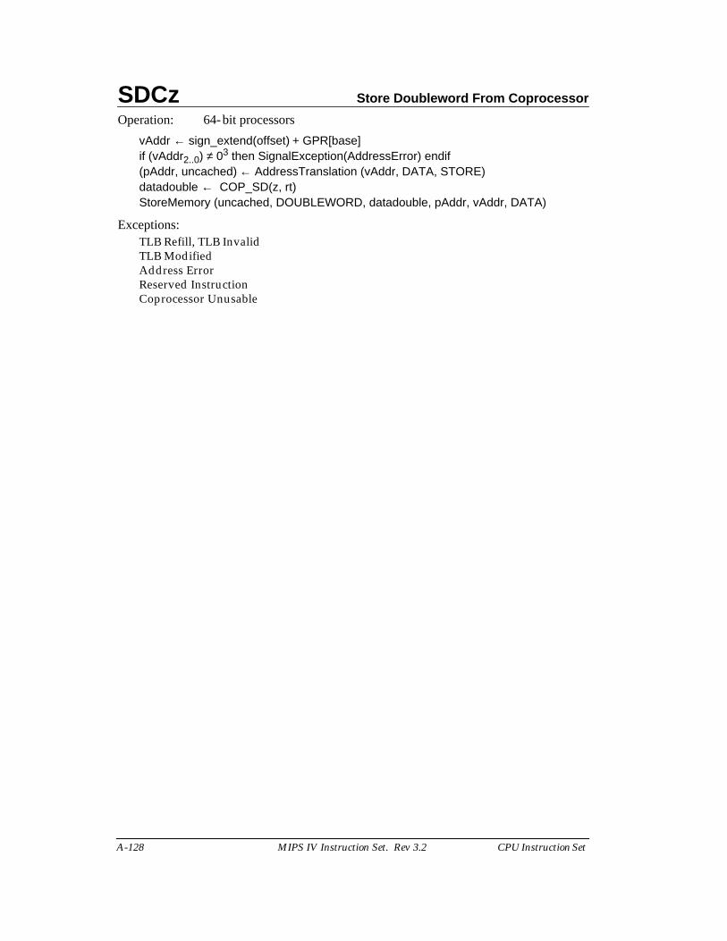
SDCz Store Doubleword From Coprocessor
A-128 MIPS IV Instruction Set. Rev 3.2 CPU Instruction Set
Operation: 64-bit processors
vAddr ← sign_extend(offset) + GPR[base]if (vAddr2..0) ≠ 03 then SignalException(AddressError) endif(pAddr, uncached) ← AddressTranslation (vAddr, DATA, STORE)datadouble ← COP_SD(z, rt)StoreMemory (uncached, DOUBLEWORD, datadouble, pAddr, vAddr, DATA)
Exceptions:TLB Refill, TLB InvalidTLB ModifiedAddress ErrorReserved InstructionCoprocessor Unusable
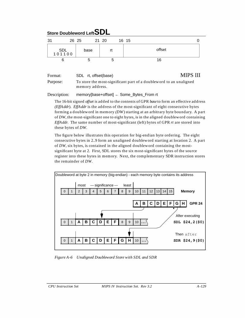
Store Doubleword Left SDL
CPU Instruction Set MIPS IV Instruction Set. Rev 3.2 A-129
Format: SDL rt, offset(base) MIPS IIIPurpose: To store the most-significant part of a doubleword to an unaligned
memory address.
Description: memory[base+offset] ← Some_Bytes_From rt
The 16-bit signed offset is added to the contents of GPR base to form an effective address(EffAddr). EffAddr is the address of the most-significant of eight consecutive bytesforming a doubleword in memory (DW) starting at an arbitrary byte boundary. A partof DW, the most-significant one to eight bytes, is in the aligned doubleword containingEffAddr. The same number of most-significant (left) bytes of GPR rt are stored intothese bytes of DW.
The figure below illustrates this operation for big-endian byte ordering. The eightconsecutive bytes in 2..9 form an unaligned doubleword starting at location 2. A partof DW, six bytes, is contained in the aligned doubleword containing the most-significant byte at 2. First, SDL stores the six most-significant bytes of the sourceregister into these bytes in memory. Next, the complementary SDR instruction storesthe remainder of DW.
Figure A-6 Unaligned Doubleword Store with SDL and SDR
31 2526 2021 1516 0
SDL base rt offset
6 5 5 161 0 1 1 0 0
Doubleword at byte 2 in memory (big-endian) - each memory byte contains its address
most — significance — least
0 1 2 3 4 5 6 7 8 9 10 11 12 13 14 15 Memory
A B C D E F G H GPR 24
After executing
0 1 A B C D E F 8 9 10 ... SDL $24,2($0)
Then after
0 1 A B C D E F G H 10 ... SDR $24,9($0)
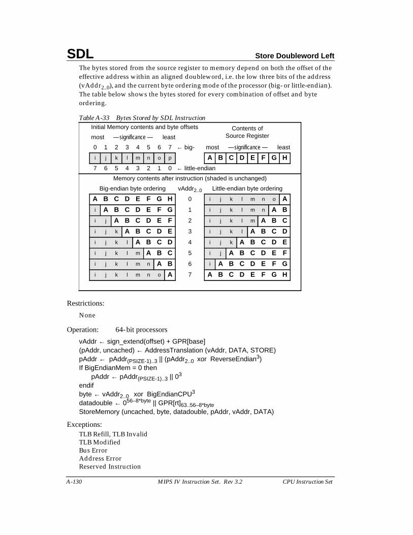
SDL Store Doubleword Left
A-130 MIPS IV Instruction Set. Rev 3.2 CPU Instruction Set
The bytes stored from the source register to memory depend on both the offset of theeffective address within an aligned doubleword, i.e. the low three bits of the address(vAddr2..0), and the current byte ordering mode of the processor (big- or little-endian).The table below shows the bytes stored for every combination of offset and byteordering.
Restrictions:
None
Operation: 64-bit processors
vAddr ← sign_extend(offset) + GPR[base](pAddr, uncached) ← AddressTranslation (vAddr, DATA, STORE)pAddr ← pAddr(PSIZE-1)..3 || (pAddr2..0 xor ReverseEndian3)If BigEndianMem = 0 then
pAddr ← pAddr(PSIZE-1)..3 || 03
endifbyte ← vAddr2..0 xor BigEndianCPU3
datadouble ← 056–8*byte || GPR[rt]63..56–8*byteStoreMemory (uncached, byte, datadouble, pAddr, vAddr, DATA)
Exceptions:TLB Refill, TLB InvalidTLB ModifiedBus ErrorAddress ErrorReserved Instruction
Table A-33 Bytes Stored by SDL InstructionInitial Memory contents and byte offsets Contents of
Source Registermost — significance — least
0 1 2 3 4 5 6 7 ← big- most — significance — least
i j k l m n o p A B C D E F G H
7 6 5 4 3 2 1 0 ← little-endian
Memory contents after instruction (shaded is unchanged)
Big-endian byte ordering vAddr2..0 Little-endian byte ordering
A B C D E F G H 0 i j k l m n o A
i A B C D E F G 1 i j k l m n A B
i j A B C D E F 2 i j k l m A B C
i j k A B C D E 3 i j k l A B C D
i j k l A B C D 4 i j k A B C D E
i j k l m A B C 5 i j A B C D E F
i j k l m n A B 6 i A B C D E F G
i j k l m n o A 7 A B C D E F G H
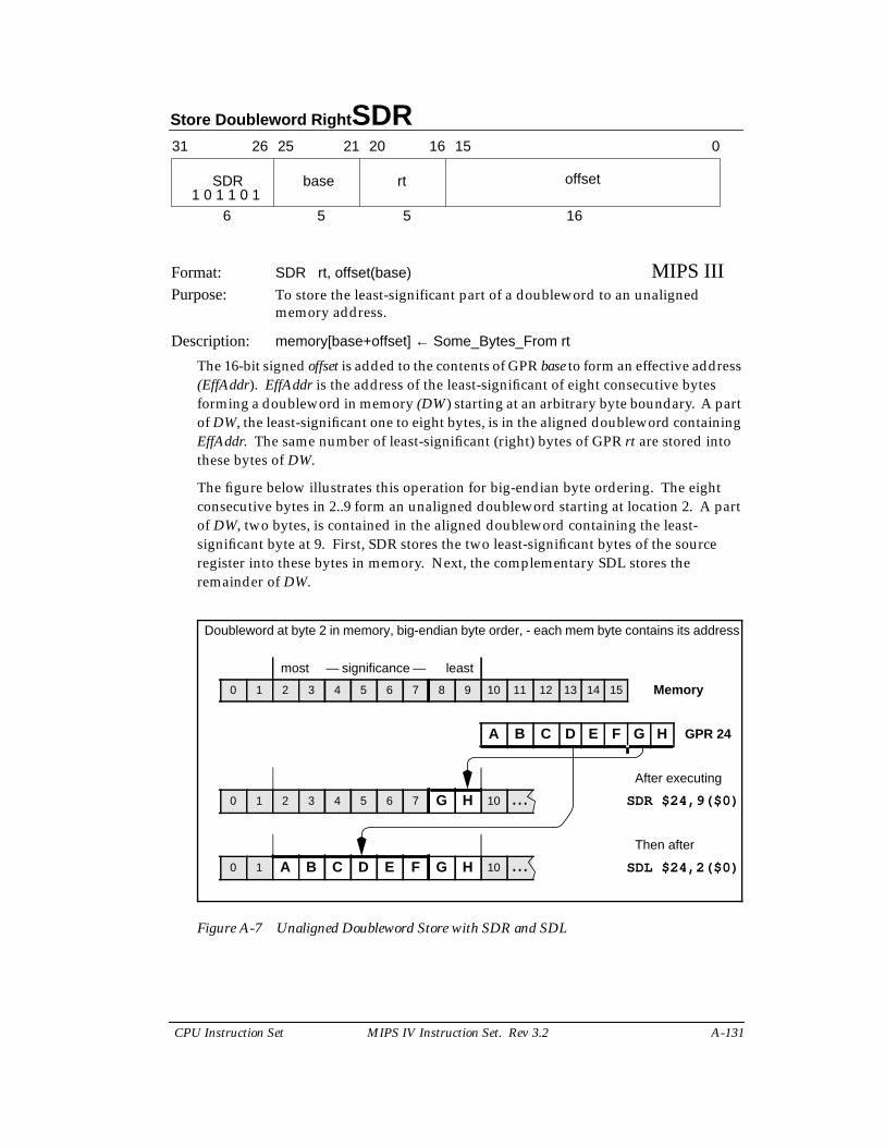
Store Doubleword Right SDR
CPU Instruction Set MIPS IV Instruction Set. Rev 3.2 A-131
Format: SDR rt, offset(base) MIPS IIIPurpose: To store the least-significant part of a doubleword to an unaligned
memory address.
Description: memory[base+offset] ← Some_Bytes_From rt
The 16-bit signed offset is added to the contents of GPR base to form an effective address(EffAddr). EffAddr is the address of the least-significant of eight consecutive bytesforming a doubleword in memory (DW) starting at an arbitrary byte boundary. A partof DW, the least-significant one to eight bytes, is in the aligned doubleword containingEffAddr. The same number of least-significant (right) bytes of GPR rt are stored intothese bytes of DW.
The figure below illustrates this operation for big-endian byte ordering. The eightconsecutive bytes in 2..9 form an unaligned doubleword starting at location 2. A partof DW, two bytes, is contained in the aligned doubleword containing the least-significant byte at 9. First, SDR stores the two least-significant bytes of the sourceregister into these bytes in memory. Next, the complementary SDL stores theremainder of DW.
Figure A-7 Unaligned Doubleword Store with SDR and SDL
31 2526 2021 1516 0
SDR base rt offset
6 5 5 161 0 1 1 0 1
Doubleword at byte 2 in memory, big-endian byte order, - each mem byte contains its address
most — significance — least
0 1 2 3 4 5 6 7 8 9 10 11 12 13 14 15 Memory
A B C D E F G H GPR 24
After executing
0 1 2 3 4 5 6 7 G H 10 ... SDR $24,9($0)
Then after
0 1 A B C D E F G H 10 ... SDL $24,2($0)
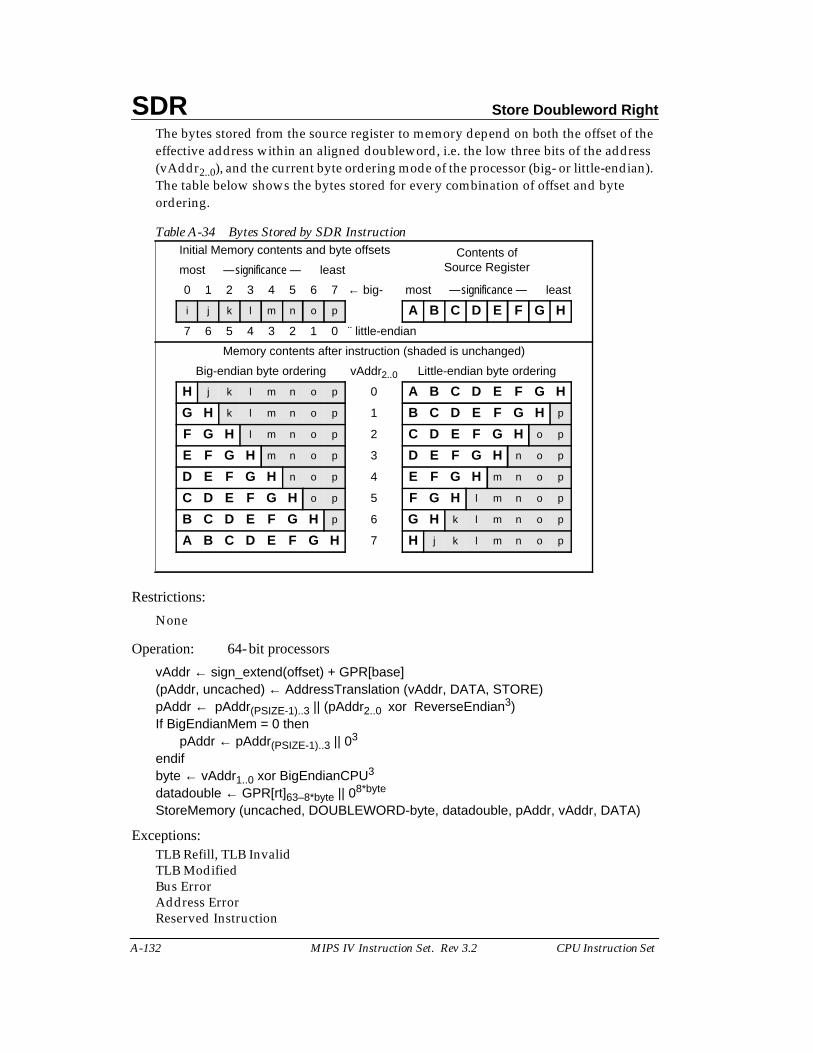
SDR Store Doubleword Right
A-132 MIPS IV Instruction Set. Rev 3.2 CPU Instruction Set
The bytes stored from the source register to memory depend on both the offset of theeffective address within an aligned doubleword, i.e. the low three bits of the address(vAddr2..0), and the current byte ordering mode of the processor (big- or little-endian).The table below shows the bytes stored for every combination of offset and byteordering.
Restrictions:
None
Operation: 64-bit processors
vAddr ← sign_extend(offset) + GPR[base](pAddr, uncached) ← AddressTranslation (vAddr, DATA, STORE)pAddr ← pAddr(PSIZE-1)..3 || (pAddr2..0 xor ReverseEndian3)If BigEndianMem = 0 then
pAddr ← pAddr(PSIZE-1)..3 || 03
endifbyte ← vAddr1..0 xor BigEndianCPU3
datadouble ← GPR[rt]63–8*byte || 08*byte
StoreMemory (uncached, DOUBLEWORD-byte, datadouble, pAddr, vAddr, DATA)
Exceptions:TLB Refill, TLB InvalidTLB ModifiedBus ErrorAddress ErrorReserved Instruction
Table A-34 Bytes Stored by SDR InstructionInitial Memory contents and byte offsets Contents of
Source Registermost — significance — least
0 1 2 3 4 5 6 7 ← big- most — significance — least
i j k l m n o p A B C D E F G H
7 6 5 4 3 2 1 0 ¨ little-endian
Memory contents after instruction (shaded is unchanged)
Big-endian byte ordering vAddr2..0 Little-endian byte ordering
H j k l m n o p 0 A B C D E F G H
G H k l m n o p 1 B C D E F G H p
F G H l m n o p 2 C D E F G H o p
E F G H m n o p 3 D E F G H n o p
D E F G H n o p 4 E F G H m n o p
C D E F G H o p 5 F G H l m n o p
B C D E F G H p 6 G H k l m n o p
A B C D E F G H 7 H j k l m n o p
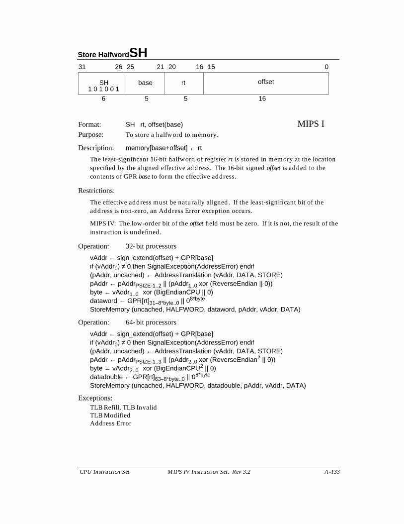
Store Halfword SH
CPU Instruction Set MIPS IV Instruction Set. Rev 3.2 A-133
Format: SH rt, offset(base) MIPS IPurpose: To store a halfword to memory.
Description: memory[base+offset] ← rt
The least-significant 16-bit halfword of register rt is stored in memory at the locationspecified by the aligned effective address. The 16-bit signed offset is added to thecontents of GPR base to form the effective address.
Restrictions:
The effective address must be naturally aligned. If the least-significant bit of theaddress is non-zero, an Address Error exception occurs.
MIPS IV: The low-order bit of the offset field must be zero. If it is not, the result of theinstruction is undefined.
Operation: 32-bit processors
vAddr ← sign_extend(offset) + GPR[base]if (vAddr0) ≠ 0 then SignalException(AddressError) endif(pAddr, uncached) ← AddressTranslation (vAddr, DATA, STORE)pAddr ← pAddrPSIZE-1..2 || (pAddr1..0 xor (ReverseEndian || 0))byte ← vAddr1..0 xor (BigEndianCPU || 0)dataword ← GPR[rt]31–8*byte..0 || 08*byte
StoreMemory (uncached, HALFWORD, dataword, pAddr, vAddr, DATA)
Operation: 64-bit processors
vAddr ← sign_extend(offset) + GPR[base]if (vAddr0) ≠ 0 then SignalException(AddressError) endif(pAddr, uncached) ← AddressTranslation (vAddr, DATA, STORE)pAddr ← pAddrPSIZE-1..3 || (pAddr2..0 xor (ReverseEndian2 || 0))byte ← vAddr2..0 xor (BigEndianCPU2 || 0)datadouble ← GPR[rt]63–8*byte..0 || 08*byte
StoreMemory (uncached, HALFWORD, datadouble, pAddr, vAddr, DATA)
Exceptions:TLB Refill, TLB InvalidTLB ModifiedAddress Error
31 2526 2021 1516 0
SH base rt offset
6 5 5 161 0 1 0 0 1
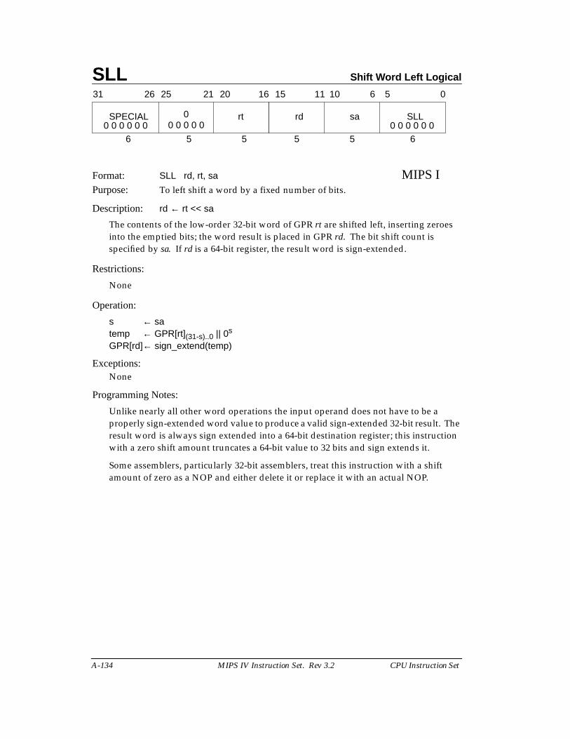
SLL Shift Word Left Logical
A-134 MIPS IV Instruction Set. Rev 3.2 CPU Instruction Set
Format: SLL rd, rt, sa MIPS IPurpose: To left shift a word by a fixed number of bits.
Description: rd ← rt << sa
The contents of the low-order 32-bit word of GPR rt are shifted left, inserting zeroesinto the emptied bits; the word result is placed in GPR rd. The bit shift count isspecified by sa. If rd is a 64-bit register, the result word is sign-extended.
Restrictions:
None
Operation:
s ← satemp ← GPR[rt](31-s)..0 || 0s
GPR[rd]← sign_extend(temp)
Exceptions:None
Programming Notes:
Unlike nearly all other word operations the input operand does not have to be aproperly sign-extended word value to produce a valid sign-extended 32-bit result. Theresult word is always sign extended into a 64-bit destination register; this instructionwith a zero shift amount truncates a 64-bit value to 32 bits and sign extends it.
Some assemblers, particularly 32-bit assemblers, treat this instruction with a shiftamount of zero as a NOP and either delete it or replace it with an actual NOP.
31 2526 2021 1516
SPECIAL 0 rt
6 5 5
rd sa SLL
5 5 6
11 10 6 5 0
0 0 0 0 0 0 0 0 0 0 0 00 0 0 0 0
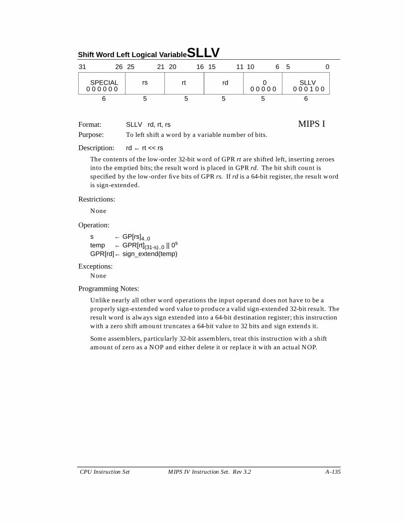
Shift Word Left Logical Variable SLLV
CPU Instruction Set MIPS IV Instruction Set. Rev 3.2 A-135
Format: SLLV rd, rt, rs MIPS IPurpose: To left shift a word by a variable number of bits.
Description: rd ← rt << rs
The contents of the low-order 32-bit word of GPR rt are shifted left, inserting zeroesinto the emptied bits; the result word is placed in GPR rd. The bit shift count isspecified by the low-order five bits of GPR rs. If rd is a 64-bit register, the result wordis sign-extended.
Restrictions:
None
Operation:
s ← GP[rs]4..0temp ← GPR[rt](31-s)..0 || 0s
GPR[rd]← sign_extend(temp)
Exceptions:None
Programming Notes:
Unlike nearly all other word operations the input operand does not have to be aproperly sign-extended word value to produce a valid sign-extended 32-bit result. Theresult word is always sign extended into a 64-bit destination register; this instructionwith a zero shift amount truncates a 64-bit value to 32 bits and sign extends it.
Some assemblers, particularly 32-bit assemblers, treat this instruction with a shiftamount of zero as a NOP and either delete it or replace it with an actual NOP.
31 2526 2021 1516
SPECIAL rt
6 5 5
rd 0 SLLV
5 5 6
11 10 6 5 0
0 0 0 0 0 0 0 0 0 1 0 00 0 0 0 0rs
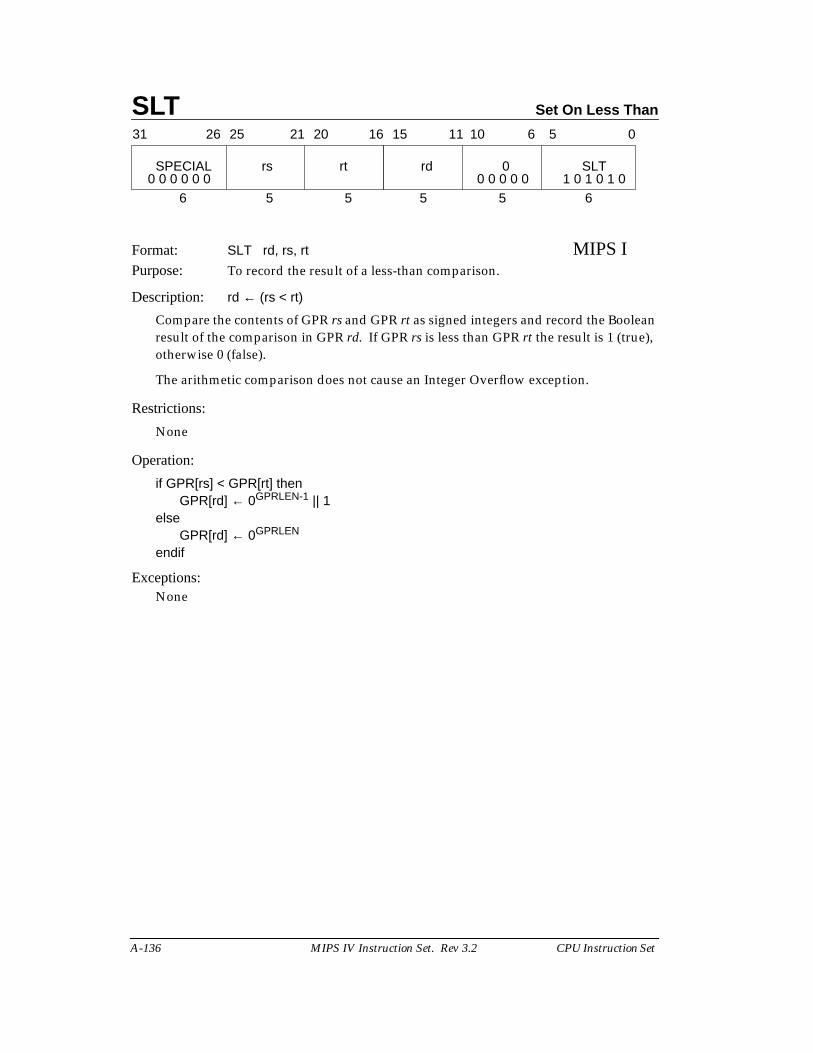
SLT Set On Less Than
A-136 MIPS IV Instruction Set. Rev 3.2 CPU Instruction Set
Format: SLT rd, rs, rt MIPS IPurpose: To record the result of a less-than comparison.
Description: rd ← (rs < rt)
Compare the contents of GPR rs and GPR rt as signed integers and record the Booleanresult of the comparison in GPR rd. If GPR rs is less than GPR rt the result is 1 (true),otherwise 0 (false).
The arithmetic comparison does not cause an Integer Overflow exception.
Restrictions:
None
Operation:
if GPR[rs] < GPR[rt] thenGPR[rd] ← 0GPRLEN-1 || 1
elseGPR[rd] ← 0GPRLEN
endif
Exceptions:None
31 2526 2021 1516
SPECIAL rs rt
6 5 5
rd 0 SLT
5 5 6
11 10 6 5 0
0 0 0 0 0 0 1 0 1 0 1 00 0 0 0 0
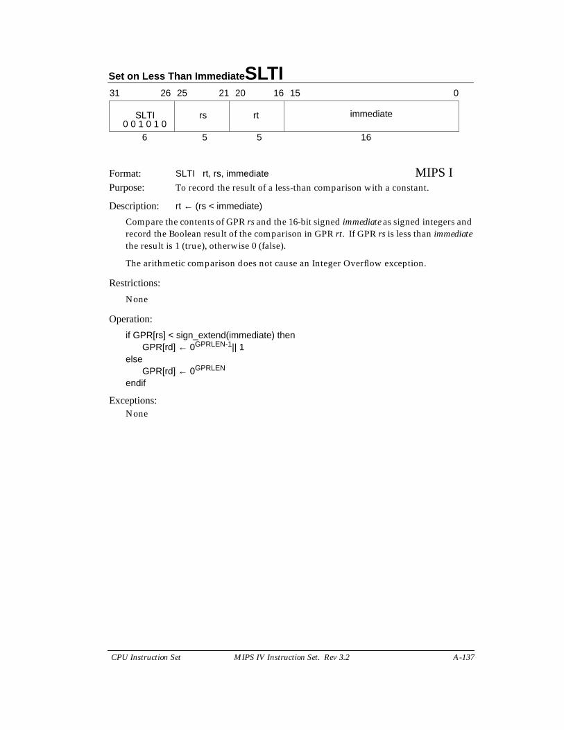
Set on Less Than Immediate SLTI
CPU Instruction Set MIPS IV Instruction Set. Rev 3.2 A-137
Format: SLTI rt, rs, immediate MIPS IPurpose: To record the result of a less-than comparison with a constant.
Description: rt ← (rs < immediate)
Compare the contents of GPR rs and the 16-bit signed immediate as signed integers andrecord the Boolean result of the comparison in GPR rt. If GPR rs is less than immediatethe result is 1 (true), otherwise 0 (false).
The arithmetic comparison does not cause an Integer Overflow exception.
Restrictions:
None
Operation:
if GPR[rs] < sign_extend(immediate) thenGPR[rd] ← 0GPRLEN-1|| 1
elseGPR[rd] ← 0GPRLEN
endif
Exceptions:None
31 2526 2021 1516 0
SLTI rs rt immediate
6 5 5 160 0 1 0 1 0
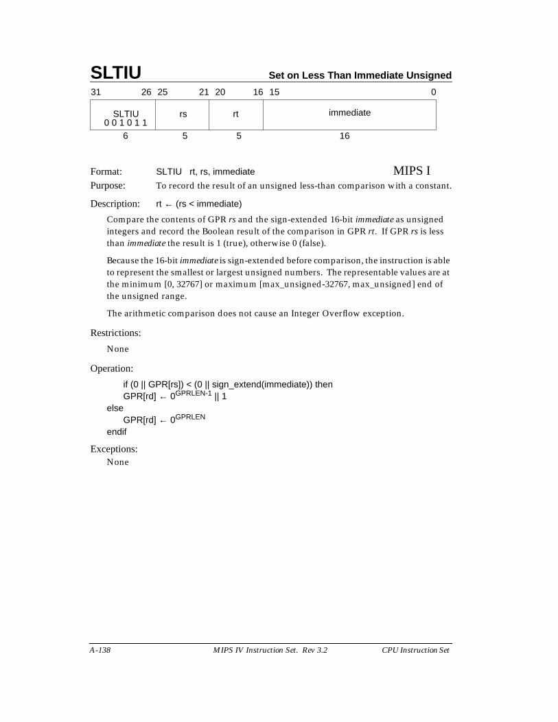
SLTIU Set on Less Than Immediate Unsigned
A-138 MIPS IV Instruction Set. Rev 3.2 CPU Instruction Set
Format: SLTIU rt, rs, immediate MIPS IPurpose: To record the result of an unsigned less-than comparison with a constant.
Description: rt ← (rs < immediate)
Compare the contents of GPR rs and the sign-extended 16-bit immediate as unsignedintegers and record the Boolean result of the comparison in GPR rt. If GPR rs is lessthan immediate the result is 1 (true), otherwise 0 (false).
Because the 16-bit immediate is sign-extended before comparison, the instruction is ableto represent the smallest or largest unsigned numbers. The representable values are atthe minimum [0, 32767] or maximum [max_unsigned-32767, max_unsigned] end ofthe unsigned range.
The arithmetic comparison does not cause an Integer Overflow exception.
Restrictions:
None
Operation:
if (0 || GPR[rs]) < (0 || sign_extend(immediate)) thenGPR[rd] ← 0GPRLEN-1 || 1
elseGPR[rd] ← 0GPRLEN
endif
Exceptions:None
31 2526 2021 1516 0
SLTIU rs rt immediate
6 5 5 160 0 1 0 1 1
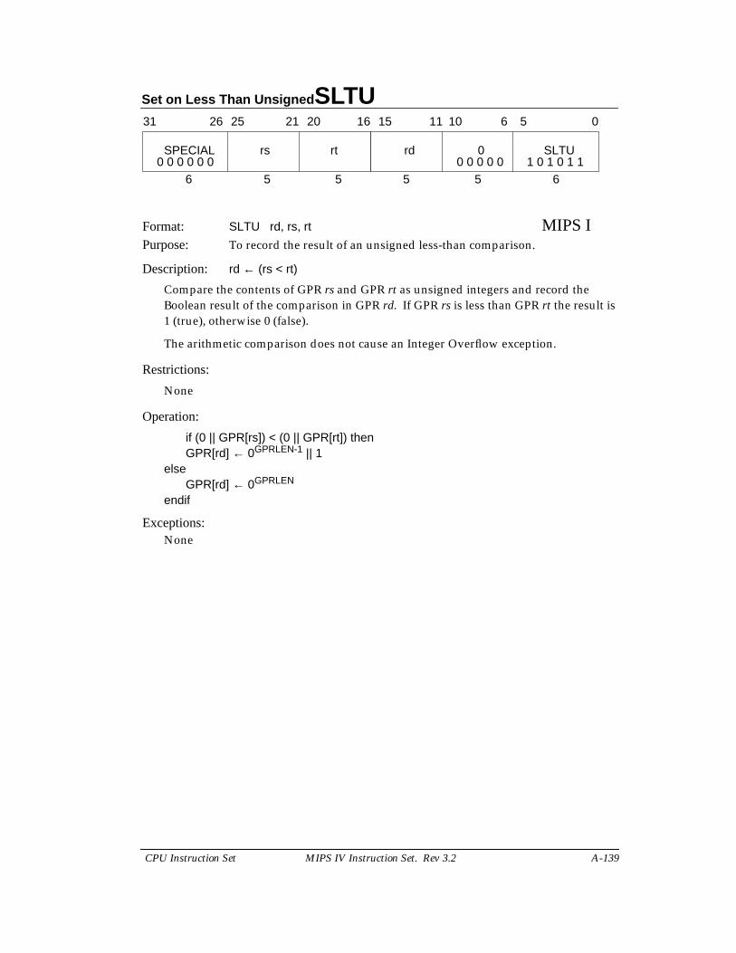
Set on Less Than Unsigned SLTU
CPU Instruction Set MIPS IV Instruction Set. Rev 3.2 A-139
Format: SLTU rd, rs, rt MIPS IPurpose: To record the result of an unsigned less-than comparison.
Description: rd ← (rs < rt)
Compare the contents of GPR rs and GPR rt as unsigned integers and record theBoolean result of the comparison in GPR rd. If GPR rs is less than GPR rt the result is1 (true), otherwise 0 (false).
The arithmetic comparison does not cause an Integer Overflow exception.
Restrictions:
None
Operation:
if (0 || GPR[rs]) < (0 || GPR[rt]) thenGPR[rd] ← 0GPRLEN-1 || 1
elseGPR[rd] ← 0GPRLEN
endif
Exceptions:None
31 2526 2021 1516
SPECIAL rs rt
6 5 5
rd 0 SLTU
5 5 6
11 10 6 5 0
0 0 0 0 0 0 0 0 0 0 0 1 0 1 0 1 1
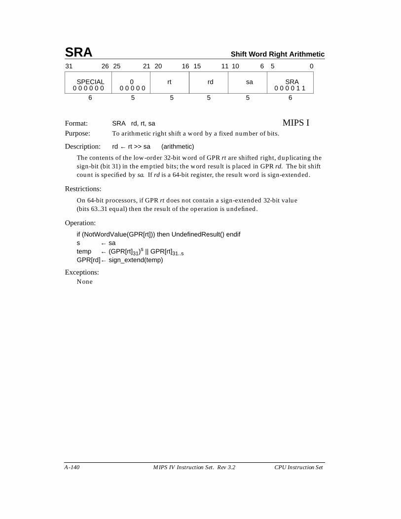
SRA Shift Word Right Arithmetic
A-140 MIPS IV Instruction Set. Rev 3.2 CPU Instruction Set
Format: SRA rd, rt, sa MIPS IPurpose: To arithmetic right shift a word by a fixed number of bits.
Description: rd ← rt >> sa (arithmetic)
The contents of the low-order 32-bit word of GPR rt are shifted right, duplicating thesign-bit (bit 31) in the emptied bits; the word result is placed in GPR rd. The bit shiftcount is specified by sa. If rd is a 64-bit register, the result word is sign-extended.
Restrictions:
On 64-bit processors, if GPR rt does not contain a sign-extended 32-bit value(bits 63..31 equal) then the result of the operation is undefined.
Operation:
if (NotWordValue(GPR[rt])) then UndefinedResult() endifs ← satemp ← (GPR[rt]31)s || GPR[rt]31..sGPR[rd]← sign_extend(temp)
Exceptions:None
31 2526 2021 1516
SPECIAL 0 rt
6 5 5
rd sa SRA
5 5 6
11 10 6 5 0
0 0 0 0 0 0 0 0 0 0 0 0 0 0 0 1 1
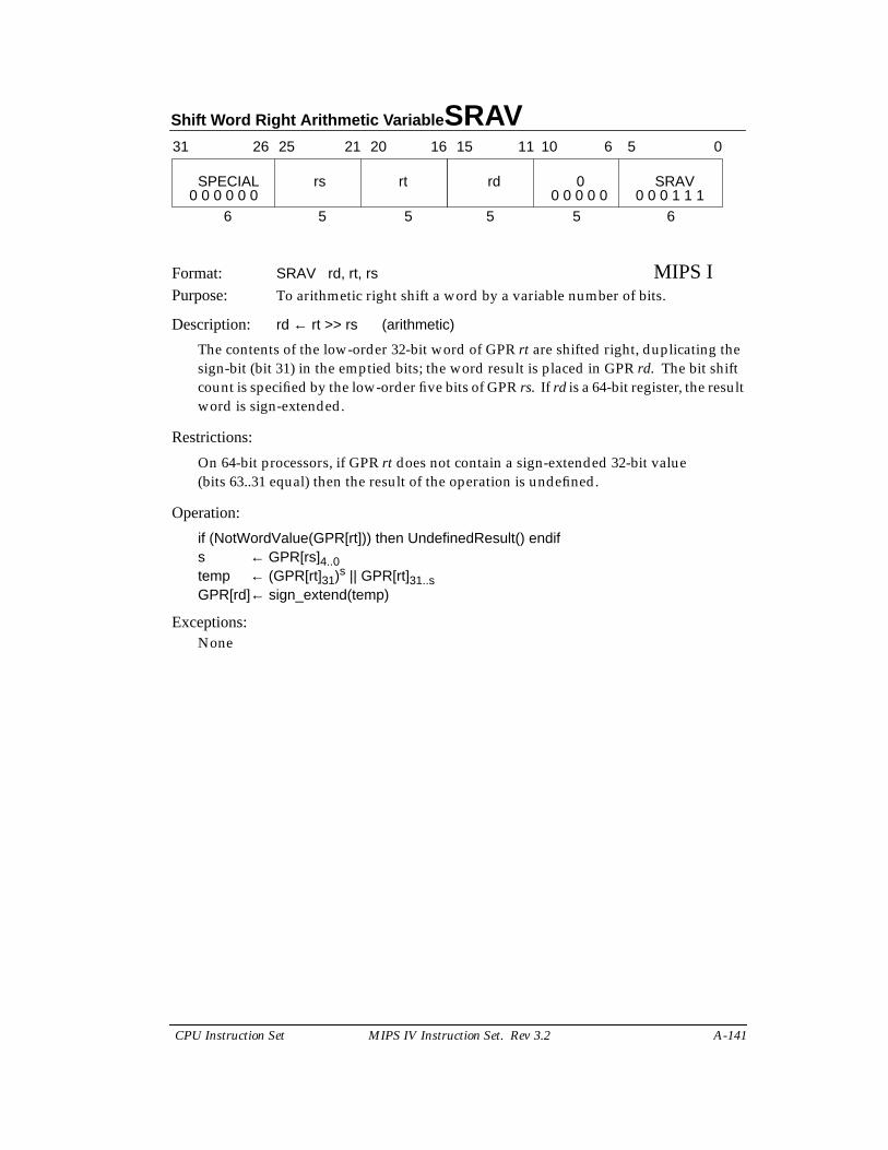
Shift Word Right Arithmetic Variable SRAV
CPU Instruction Set MIPS IV Instruction Set. Rev 3.2 A-141
Format: SRAV rd, rt, rs MIPS IPurpose: To arithmetic right shift a word by a variable number of bits.
Description: rd ← rt >> rs (arithmetic)
The contents of the low-order 32-bit word of GPR rt are shifted right, duplicating thesign-bit (bit 31) in the emptied bits; the word result is placed in GPR rd. The bit shiftcount is specified by the low-order five bits of GPR rs. If rd is a 64-bit register, the resultword is sign-extended.
Restrictions:
On 64-bit processors, if GPR rt does not contain a sign-extended 32-bit value(bits 63..31 equal) then the result of the operation is undefined.
Operation:
if (NotWordValue(GPR[rt])) then UndefinedResult() endifs ← GPR[rs]4..0temp ← (GPR[rt]31)s || GPR[rt]31..sGPR[rd]← sign_extend(temp)
Exceptions:None
31 2526 2021 1516
SPECIAL rs rt
6 5 5
rd 0 SRAV
5 5 6
11 10 6 5 0
0 0 0 0 0 0 0 0 0 0 0 0 0 0 1 1 1
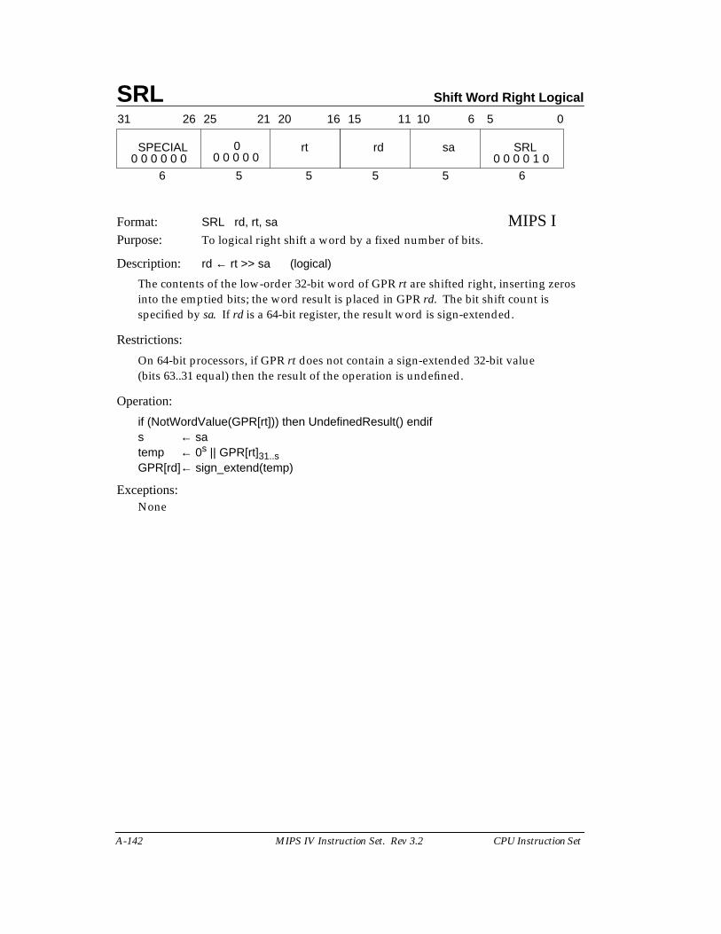
SRL Shift Word Right Logical
A-142 MIPS IV Instruction Set. Rev 3.2 CPU Instruction Set
Format: SRL rd, rt, sa MIPS IPurpose: To logical right shift a word by a fixed number of bits.
Description: rd ← rt >> sa (logical)
The contents of the low-order 32-bit word of GPR rt are shifted right, inserting zerosinto the emptied bits; the word result is placed in GPR rd. The bit shift count isspecified by sa. If rd is a 64-bit register, the result word is sign-extended.
Restrictions:
On 64-bit processors, if GPR rt does not contain a sign-extended 32-bit value(bits 63..31 equal) then the result of the operation is undefined.
Operation:
if (NotWordValue(GPR[rt])) then UndefinedResult() endifs ← satemp ← 0s || GPR[rt]31..sGPR[rd]← sign_extend(temp)
Exceptions:None
31 2526 2021 1516
SPECIAL rt
6 5 5
rd sa SRL
5 5 6
11 10 6 5 0
0 0 0 0 0 0 0 0 0 0 1 00
0 0 0 0 0
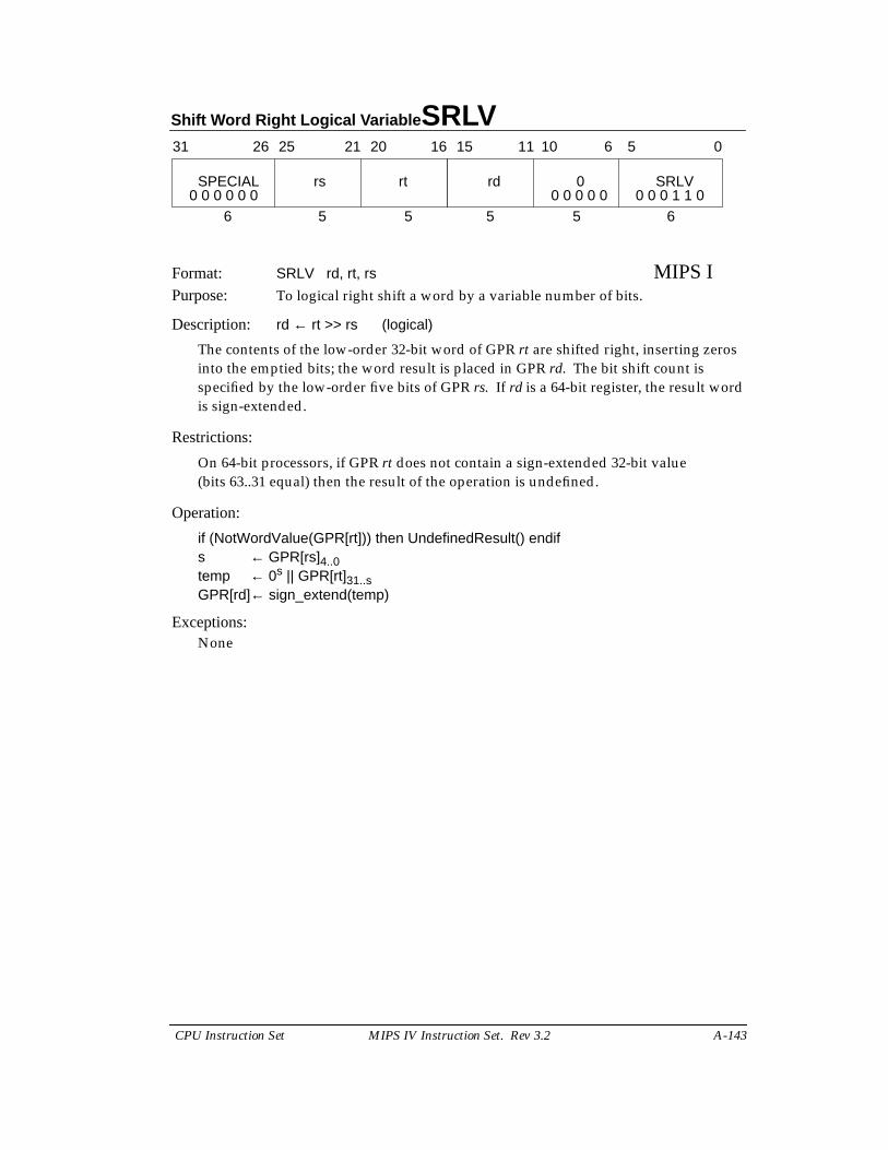
Shift Word Right Logical Variable SRLV
CPU Instruction Set MIPS IV Instruction Set. Rev 3.2 A-143
Format: SRLV rd, rt, rs MIPS IPurpose: To logical right shift a word by a variable number of bits.
Description: rd ← rt >> rs (logical)
The contents of the low-order 32-bit word of GPR rt are shifted right, inserting zerosinto the emptied bits; the word result is placed in GPR rd. The bit shift count isspecified by the low-order five bits of GPR rs. If rd is a 64-bit register, the result wordis sign-extended.
Restrictions:
On 64-bit processors, if GPR rt does not contain a sign-extended 32-bit value(bits 63..31 equal) then the result of the operation is undefined.
Operation:
if (NotWordValue(GPR[rt])) then UndefinedResult() endifs ← GPR[rs]4..0temp ← 0s || GPR[rt]31..sGPR[rd]← sign_extend(temp)
Exceptions:None
31 2526 2021 1516
SPECIAL rs rt
6 5 5
rd 0 SRLV
5 5 6
11 10 6 5 0
0 0 0 0 0 0 0 0 0 0 0 0 0 0 1 1 0
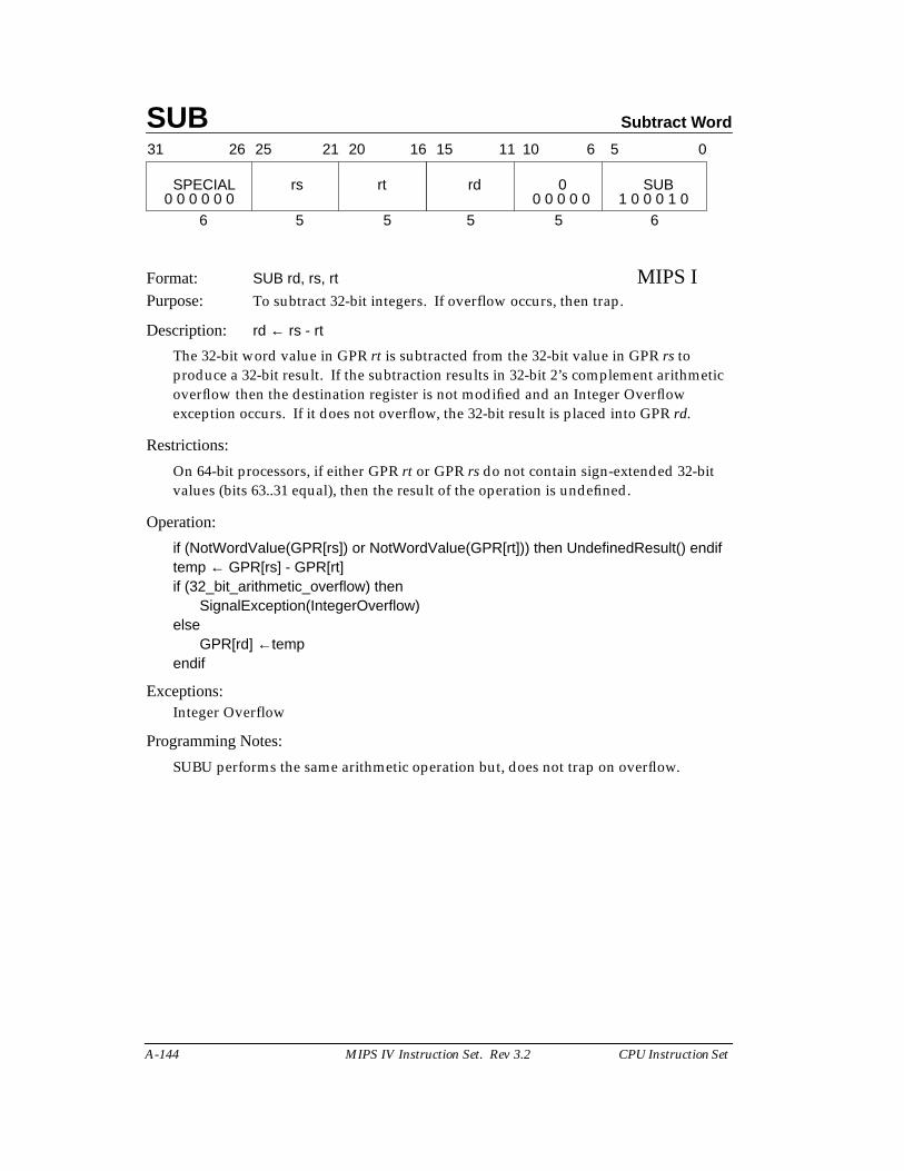
SUB Subtract Word
A-144 MIPS IV Instruction Set. Rev 3.2 CPU Instruction Set
Format: SUB rd, rs, rt MIPS IPurpose: To subtract 32-bit integers. If overflow occurs, then trap.
Description: rd ← rs - rt
The 32-bit word value in GPR rt is subtracted from the 32-bit value in GPR rs toproduce a 32-bit result. If the subtraction results in 32-bit 2’s complement arithmeticoverflow then the destination register is not modified and an Integer Overflowexception occurs. If it does not overflow, the 32-bit result is placed into GPR rd.
Restrictions:
On 64-bit processors, if either GPR rt or GPR rs do not contain sign-extended 32-bitvalues (bits 63..31 equal), then the result of the operation is undefined.
Operation:
if (NotWordValue(GPR[rs]) or NotWordValue(GPR[rt])) then UndefinedResult() endiftemp ← GPR[rs] - GPR[rt]if (32_bit_arithmetic_overflow) then
SignalException(IntegerOverflow)else
GPR[rd] ←tempendif
Exceptions:Integer Overflow
Programming Notes:
SUBU performs the same arithmetic operation but, does not trap on overflow.
31 2526 2021 1516
SPECIAL rs rt
6 5 5
rd 0 SUB
5 5 6
11 10 6 5 0
0 0 0 0 0 0 0 0 0 0 0 1 0 0 0 1 0
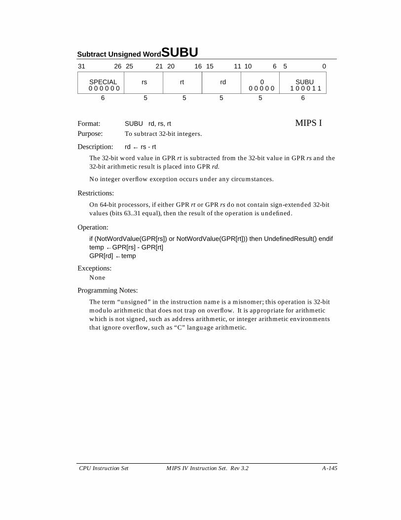
Subtract Unsigned Word SUBU
CPU Instruction Set MIPS IV Instruction Set. Rev 3.2 A-145
Format: SUBU rd, rs, rt MIPS IPurpose: To subtract 32-bit integers.
Description: rd ← rs - rt
The 32-bit word value in GPR rt is subtracted from the 32-bit value in GPR rs and the32-bit arithmetic result is placed into GPR rd.
No integer overflow exception occurs under any circumstances.
Restrictions:
On 64-bit processors, if either GPR rt or GPR rs do not contain sign-extended 32-bitvalues (bits 63..31 equal), then the result of the operation is undefined.
Operation:
if (NotWordValue(GPR[rs]) or NotWordValue(GPR[rt])) then UndefinedResult() endiftemp ←GPR[rs] - GPR[rt]GPR[rd] ←temp
Exceptions:None
Programming Notes:
The term “unsigned” in the instruction name is a misnomer; this operation is 32-bitmodulo arithmetic that does not trap on overflow. It is appropriate for arithmeticwhich is not signed, such as address arithmetic, or integer arithmetic environmentsthat ignore overflow, such as “C” language arithmetic.
31 2526 2021 1516
SPECIAL rs rt
6 5 5
rd 0 SUBU
5 5 6
11 10 6 5 0
0 0 0 0 0 0 0 0 0 0 0 1 0 0 0 1 1
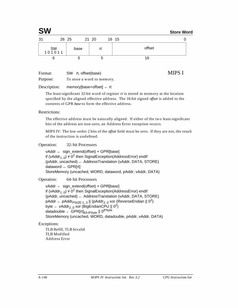
SW Store Word
A-146 MIPS IV Instruction Set. Rev 3.2 CPU Instruction Set
Format: SW rt, offset(base) MIPS IPurpose: To store a word to memory.
Description: memory[base+offset] ← rt
The least-significant 32-bit word of register rt is stored in memory at the locationspecified by the aligned effective address. The 16-bit signed offset is added to thecontents of GPR base to form the effective address.
Restrictions:
The effective address must be naturally aligned. If either of the two least-significantbits of the address are non-zero, an Address Error exception occurs.
MIPS IV: The low-order 2 bits of the offset field must be zero. If they are not, the resultof the instruction is undefined.
Operation: 32-bit Processors
vAddr ← sign_extend(offset) + GPR[base]if (vAddr1..0) ≠ 02 then SignalException(AddressError) endif(pAddr, uncached) ← AddressTranslation (vAddr, DATA, STORE)dataword ← GPR[rt]StoreMemory (uncached, WORD, dataword, pAddr, vAddr, DATA)
Operation: 64-bit Processors
vAddr ← sign_extend(offset) + GPR[base]if (vAddr1..0) ≠ 02 then SignalException(AddressError) endif(pAddr, uncached) ← AddressTranslation (vAddr, DATA, STORE)pAddr ← pAddrPSIZE-1..3 || (pAddr2..0 xor (ReverseEndian || 02)byte ← vAddr2..0 xor (BigEndianCPU || 02)datadouble ← GPR[rt]63-8*byte || 08*byte
StoreMemory (uncached, WORD, datadouble, pAddr, vAddr, DATA)
Exceptions:TLB Refill, TLB InvalidTLB ModifiedAddress Error
31 2526 2021 1516 0
SW base rt offset
6 5 5 161 0 1 0 1 1
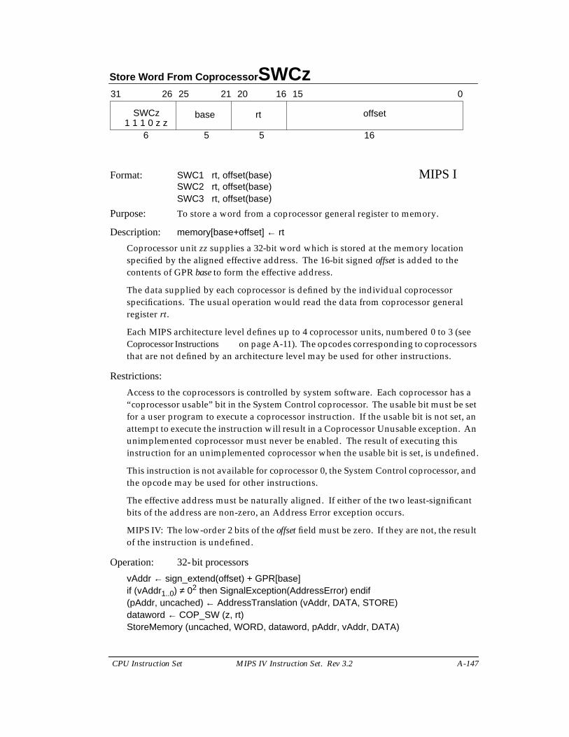
Store Word From Coprocessor SWCz
CPU Instruction Set MIPS IV Instruction Set. Rev 3.2 A-147
Format: SWC1 rt, offset(base) MIPS ISWC2 rt, offset(base)SWC3 rt, offset(base)
Purpose: To store a word from a coprocessor general register to memory.
Description: memory[base+offset] ← rt
Coprocessor unit zz supplies a 32-bit word which is stored at the memory locationspecified by the aligned effective address. The 16-bit signed offset is added to thecontents of GPR base to form the effective address.
The data supplied by each coprocessor is defined by the individual coprocessorspecifications. The usual operation would read the data from coprocessor generalregister rt.
Each MIPS architecture level defines up to 4 coprocessor units, numbered 0 to 3 (seeCoprocessor Instructions on page A-11). The opcodes corresponding to coprocessorsthat are not defined by an architecture level may be used for other instructions.
Restrictions:
Access to the coprocessors is controlled by system software. Each coprocessor has a“coprocessor usable” bit in the System Control coprocessor. The usable bit must be setfor a user program to execute a coprocessor instruction. If the usable bit is not set, anattempt to execute the instruction will result in a Coprocessor Unusable exception. Anunimplemented coprocessor must never be enabled. The result of executing thisinstruction for an unimplemented coprocessor when the usable bit is set, is undefined.
This instruction is not available for coprocessor 0, the System Control coprocessor, andthe opcode may be used for other instructions.
The effective address must be naturally aligned. If either of the two least-significantbits of the address are non-zero, an Address Error exception occurs.
MIPS IV: The low-order 2 bits of the offset field must be zero. If they are not, the resultof the instruction is undefined.
Operation: 32-bit processors
vAddr ← sign_extend(offset) + GPR[base]if (vAddr1..0) ≠ 02 then SignalException(AddressError) endif(pAddr, uncached) ← AddressTranslation (vAddr, DATA, STORE)dataword ← COP_SW (z, rt)StoreMemory (uncached, WORD, dataword, pAddr, vAddr, DATA)
31 2526 2021 1516 0
SWCz base rt offset
6 5 5 161 1 1 0 z z
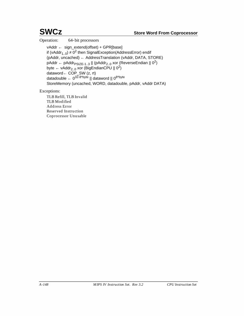
SWCz Store Word From Coprocessor
A-148 MIPS IV Instruction Set. Rev 3.2 CPU Instruction Set
Operation: 64-bit processors
vAddr ← sign_extend(offset) + GPR[base]if (vAddr1..0) ≠ 02 then SignalException(AddressError) endif(pAddr, uncached) ← AddressTranslation (vAddr, DATA, STORE)pAddr ← pAddrPSIZE-1..3 || (pAddr2..0 xor (ReverseEndian || 02)byte ← vAddr2..0 xor (BigEndianCPU || 02)dataword← COP_SW (z, rt)datadouble ← 032-8*byte || dataword || 08*byte
StoreMemory (uncached, WORD, datadouble, pAddr, vAddr DATA)
Exceptions:TLB Refill, TLB InvalidTLB ModifiedAddress ErrorReserved InstructionCoprocessor Unusable
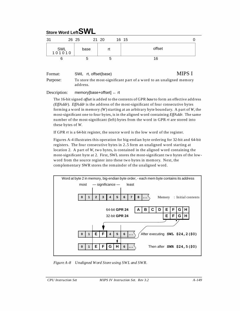
Store Word Left SWL
CPU Instruction Set MIPS IV Instruction Set. Rev 3.2 A-149
Format: SWL rt, offset(base) MIPS IPurpose: To store the most-significant part of a word to an unaligned memory
address.
Description: memory[base+offset] ← rt
The 16-bit signed offset is added to the contents of GPR base to form an effective address(EffAddr). EffAddr is the address of the most-significant of four consecutive bytesforming a word in memory (W) starting at an arbitrary byte boundary. A part of W, themost-significant one to four bytes, is in the aligned word containing EffAddr. The samenumber of the most-significant (left) bytes from the word in GPR rt are stored intothese bytes of W.
If GPR rt is a 64-bit register, the source word is the low word of the register.
Figures A-4 illustrates this operation for big-endian byte ordering for 32-bit and 64-bitregisters. The four consecutive bytes in 2..5 form an unaligned word starting atlocation 2. A part of W, two bytes, is contained in the aligned word containing themost-significant byte at 2. First, SWL stores the most-significant two bytes of the low-word from the source register into these two bytes in memory. Next, thecomplementary SWR stores the remainder of the unaligned word.
Figure A-8 Unaligned Word Store using SWL and SWR.
31 2526 2021 1516 0
SWL base rt offset
6 5 5 161 0 1 0 1 0
Word at byte 2 in memory, big-endian byte order, - each mem byte contains its address
most — significance — least
0 1 2 3 4 5 6 7 8 ... Memory : Initial contents
64-bit GPR 24 A B C D E F G H
32-bit GPR 24 E F G H
0 1 E F 4 5 6 ... After executing SWL $24,2($0)
0 1 E F G H 6 ... Then after SWR $24,5($0)
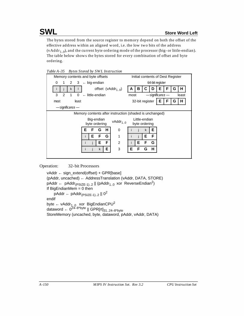
SWL Store Word Left
A-150 MIPS IV Instruction Set. Rev 3.2 CPU Instruction Set
The bytes stored from the source register to memory depend on both the offset of theeffective address within an aligned word, i.e. the low two bits of the address(vAddr1..0), and the current byte ordering mode of the processor (big- or little-endian).The table below shows the bytes stored for every combination of offset and byteordering.
Operation: 32-bit Processors
vAddr ← sign_extend(offset) + GPR[base](pAddr, uncached) ← AddressTranslation (vAddr, DATA, STORE)pAddr ← pAddr(PSIZE-1)..2 || (pAddr1..0 xor ReverseEndian2)If BigEndianMem = 0 then
pAddr ← pAddr(PSIZE-1)..2 || 02
endifbyte ← vAddr1..0 xor BigEndianCPU2
dataword ← 024–8*byte || GPR[rt]31..24–8*byteStoreMemory (uncached, byte, dataword, pAddr, vAddr, DATA)
Table A-35 Bytes Stored by SWL InstructionMemory contents and byte offsets Initial contents of Dest Register
0 1 2 3 ← big-endian 64-bit register
i j k l offset (vAddr1..0) A B C D E F G H
3 2 1 0 ← little-endian most — significance — least
most least 32-bit register E F G H
— significance —
Memory contents after instruction (shaded is unchanged)
Big-endianbyte ordering
vAddr1..0Little-endianbyte ordering
E F G H 0 i j k E
i E F G 1 i j E F
i j E F 2 i E F G
i j k E 3 E F G H
Store Word Left SWL
CPU Instruction Set MIPS IV Instruction Set. Rev 3.2 A-151
Operation: 64-bit Processors
vAddr ← sign_extend(offset) + GPR[base](pAddr, uncached) ← AddressTranslation (vAddr, DATA, STORE)pAddr ← pAddr(PSIZE-1)..3 || (pAddr2..0 xor ReverseEndian3)If BigEndianMem = 0 then
pAddr ← pAddr(PSIZE-1)..2 || 02
endifbyte ← vAddr1..0 xor BigEndianCPU2
if (vAddr2 xor BigEndianCPU) = 0 thendatadouble ← 032 || 024-8*byte || GPR[rt]31..24-8*byte
elsedatadouble ← 024-8*byte || GPR[rt]31..24-8*byte || 032
endifStoreMemory(uncached, byte, datadouble, pAddr, vAddr, DATA)
Exceptions:TLB Refill, TLB InvalidTLB ModifiedBus ErrorAddress Error
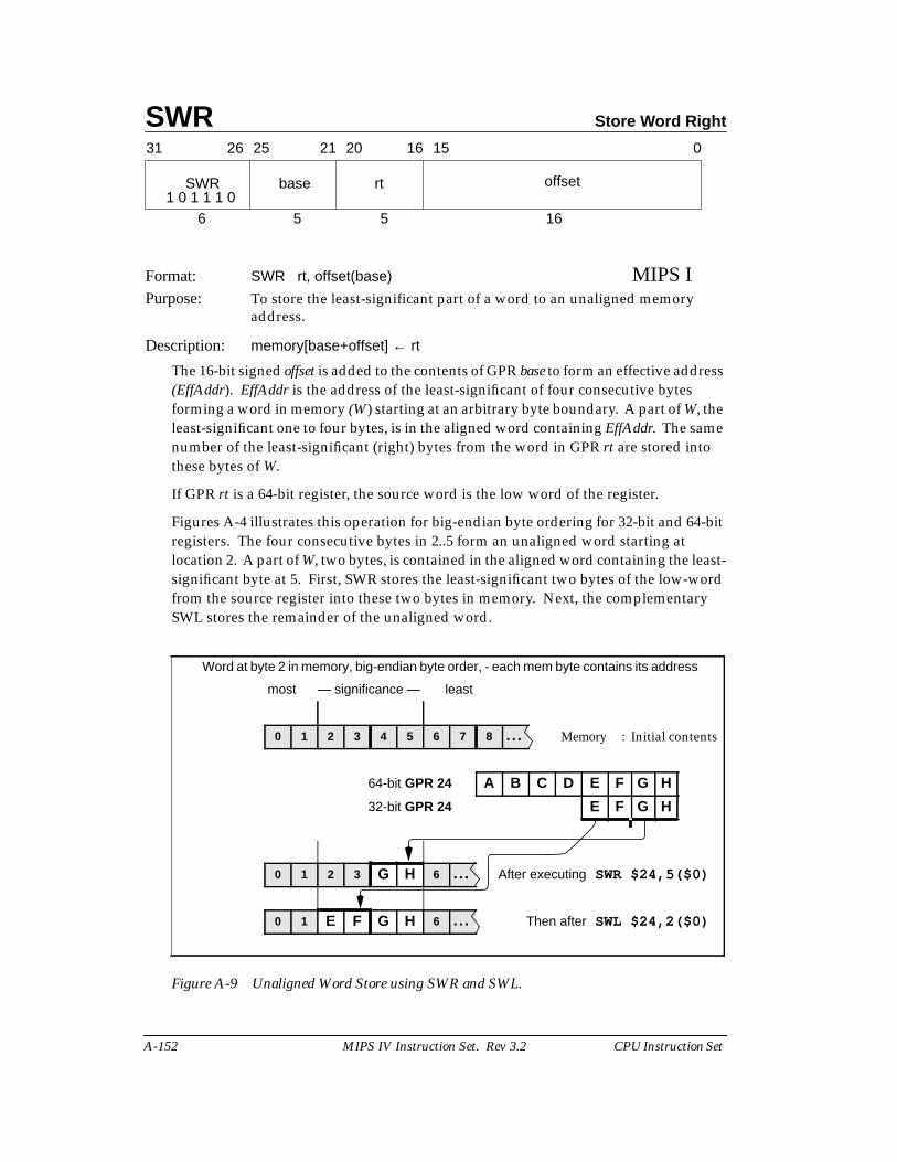
SWR Store Word Right
A-152 MIPS IV Instruction Set. Rev 3.2 CPU Instruction Set
Format: SWR rt, offset(base) MIPS IPurpose: To store the least-significant part of a word to an unaligned memory
address.
Description: memory[base+offset] ← rt
The 16-bit signed offset is added to the contents of GPR base to form an effective address(EffAddr). EffAddr is the address of the least-significant of four consecutive bytesforming a word in memory (W) starting at an arbitrary byte boundary. A part of W, theleast-significant one to four bytes, is in the aligned word containing EffAddr. The samenumber of the least-significant (right) bytes from the word in GPR rt are stored intothese bytes of W.
If GPR rt is a 64-bit register, the source word is the low word of the register.
Figures A-4 illustrates this operation for big-endian byte ordering for 32-bit and 64-bitregisters. The four consecutive bytes in 2..5 form an unaligned word starting atlocation 2. A part of W, two bytes, is contained in the aligned word containing the least-significant byte at 5. First, SWR stores the least-significant two bytes of the low-wordfrom the source register into these two bytes in memory. Next, the complementarySWL stores the remainder of the unaligned word.
Figure A-9 Unaligned Word Store using SWR and SWL.
31 2526 2021 1516 0
SWR base rt offset
6 5 5 161 0 1 1 1 0
Word at byte 2 in memory, big-endian byte order, - each mem byte contains its address
most — significance — least
0 1 2 3 4 5 6 7 8 ... Memory : Initial contents
64-bit GPR 24 A B C D E F G H
32-bit GPR 24 E F G H
0 1 2 3 G H 6 ... After executing SWR $24,5($0)
0 1 E F G H 6 ... Then after SWL $24,2($0)
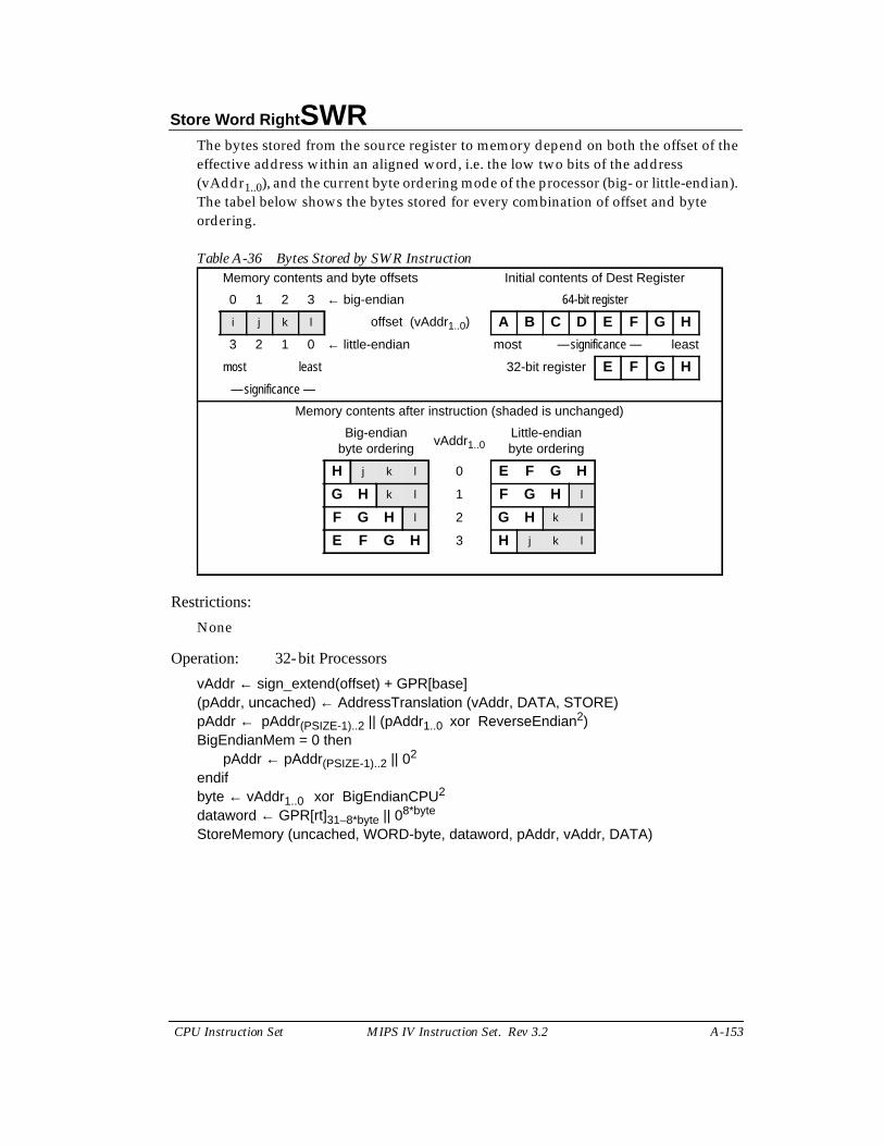
Store Word Right SWR
CPU Instruction Set MIPS IV Instruction Set. Rev 3.2 A-153
The bytes stored from the source register to memory depend on both the offset of theeffective address within an aligned word, i.e. the low two bits of the address(vAddr1..0), and the current byte ordering mode of the processor (big- or little-endian).The tabel below shows the bytes stored for every combination of offset and byteordering.
Restrictions:
None
Operation: 32-bit Processors
vAddr ← sign_extend(offset) + GPR[base](pAddr, uncached) ← AddressTranslation (vAddr, DATA, STORE)pAddr ← pAddr(PSIZE-1)..2 || (pAddr1..0 xor ReverseEndian2)BigEndianMem = 0 then
pAddr ← pAddr(PSIZE-1)..2 || 02
endifbyte ← vAddr1..0 xor BigEndianCPU2
dataword ← GPR[rt]31–8*byte || 08*byte
StoreMemory (uncached, WORD-byte, dataword, pAddr, vAddr, DATA)
Table A-36 Bytes Stored by SWR InstructionMemory contents and byte offsets Initial contents of Dest Register
0 1 2 3 ← big-endian 64-bit register
i j k l offset (vAddr1..0) A B C D E F G H
3 2 1 0 ← little-endian most — significance — least
most least 32-bit register E F G H
— significance —
Memory contents after instruction (shaded is unchanged)
Big-endianbyte ordering
vAddr1..0Little-endianbyte ordering
H j k l 0 E F G H
G H k l 1 F G H l
F G H l 2 G H k l
E F G H 3 H j k l
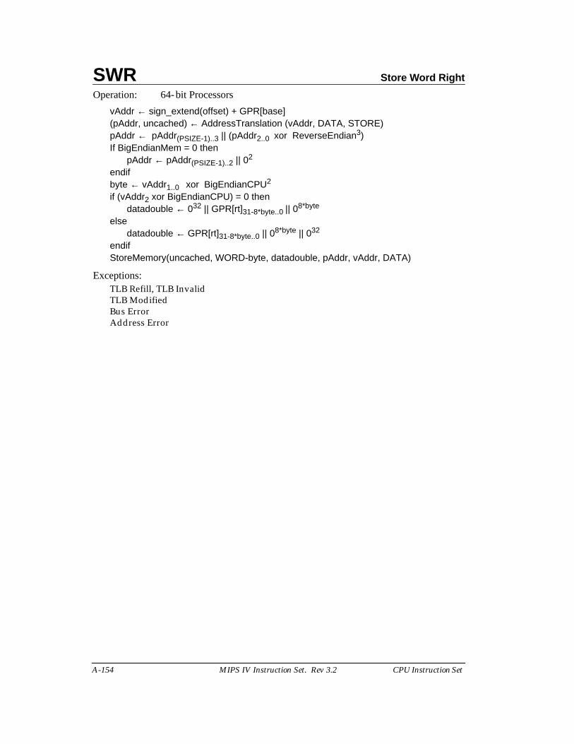
SWR Store Word Right
A-154 MIPS IV Instruction Set. Rev 3.2 CPU Instruction Set
Operation: 64-bit Processors
vAddr ← sign_extend(offset) + GPR[base](pAddr, uncached) ← AddressTranslation (vAddr, DATA, STORE)pAddr ← pAddr(PSIZE-1)..3 || (pAddr2..0 xor ReverseEndian3)If BigEndianMem = 0 then
pAddr ← pAddr(PSIZE-1)..2 || 02
endifbyte ← vAddr1..0 xor BigEndianCPU2
if (vAddr2 xor BigEndianCPU) = 0 thendatadouble ← 032 || GPR[rt]31-8*byte..0 || 08*byte
elsedatadouble ← GPR[rt]31-8*byte..0 || 08*byte || 032
endifStoreMemory(uncached, WORD-byte, datadouble, pAddr, vAddr, DATA)
Exceptions:TLB Refill, TLB InvalidTLB ModifiedBus ErrorAddress Error
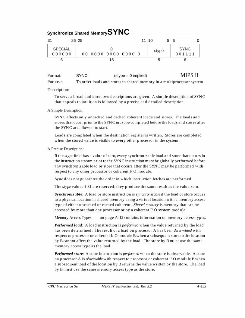
Synchronize Shared Memory SYNC
CPU Instruction Set MIPS IV Instruction Set. Rev 3.2 A-155
Format: SYNC (stype = 0 implied) MIPS IIPurpose: To order loads and stores to shared memory in a multiprocessor system.
Description:
To serve a broad audience, two descriptions are given. A simple description of SYNCthat appeals to intuition is followed by a precise and detailed description.
A Simple Description:
SYNC affects only uncached and cached coherent loads and stores. The loads andstores that occur prior to the SYNC must be completed before the loads and stores afterthe SYNC are allowed to start.
Loads are completed when the destination register is written. Stores are completedwhen the stored value is visible to every other processor in the system.
A Precise Description:
If the stype field has a value of zero, every synchronizable load and store that occurs inthe instruction stream prior to the SYNC instruction must be globally performed beforeany synchronizable load or store that occurs after the SYNC may be performed withrespect to any other processor or coherent I/O module.
Sync does not guarantee the order in which instruction fetches are performed.
The stype values 1-31 are reserved; they produce the same result as the value zero.
Synchronizable: A load or store instruction is synchronizable if the load or store occursto a physical location in shared memory using a virtual location with a memory accesstype of either uncached or cached coherent. Shared memory is memory that can beaccessed by more than one processor or by a coherent I/O system module.
Memory Access Types on page A-12 contains information on memory access types.
Performed load: A load instruction is performed when the value returned by the loadhas been determined. The result of a load on processor A has been determined withrespect to processor or coherent I/O module B when a subsequent store to the locationby B cannot affect the value returned by the load. The store by B must use the samememory access type as the load.
Performed store: A store instruction is performed when the store is observable. A storeon processor A is observable with respect to processor or coherent I/O module B whena subsequent load of the location by B returns the value written by the store. The loadby B must use the same memory access type as the store.
31 2526
SPECIAL
6 15
0 SYNC
6
6 5 0
0 0 0 0 0 0 0 0 0 0 0 0 0 0 0 0 0 0 0 0 0 0 0 1 1 1 1stype
5
1011
SYNC Synchronize Shared Memory
A-156 MIPS IV Instruction Set. Rev 3.2 CPU Instruction Set
Globally performed load: A load instruction is globally performed when it is performedwith respect to all processors and coherent I/O modules capable of storing to thelocation.
Globally performed store: A store instruction is globally performed when it is globallyobservable. It is globally observable when it observable by all processors and I/Omodules capable of loading from the location.
Coherent I/O module: A coherent I/O module is an Input/Output system componentthat performs coherent Direct Memory Access (DMA). It reads and writes memoryindependently as though it were a processor doing loads and stores to locations witha memory access type of cached coherent.
Restrictions:
The effect of SYNC on the global order of the effects of loads and stores for memoryaccess types other than uncached and cached coherent is not defined.
Operation:
SyncOperation(stype)
Exceptions:Reserved Instruction
Programming Notes:
A processor executing load and store instructions observes the effects of the loads andstores that use the same memory access type in the order that they occur in theinstruction stream; this is known as program order. A parallel program has multipleinstruction streams that can execute at the same time on different processors. Inmultiprocessor (MP) systems, the order in which the effects of loads and stores areobserved by other processors, the global order of the loads and stores, determines theactions necessary to reliably share data in parallel programs.
When all processors observe the effects of loads and stores in program order, thesystem is strongly ordered. On such systems, parallel programs can reliably share datawithout explicit actions in the programs. For such a system, SYNC has the same effectas a NOP. Executing SYNC on such a system is not necessary, but is also not an error.
If a multiprocessor system is not strongly ordered, the effects of load and storeinstructions executed by one processor may be observed out of program order by otherprocessors. On such systems, parallel programs must take explicit actions in order toreliably share data. At critical points in the program, the effects of loads and storesfrom an instruction stream must occur in the same order for all processors. SYNCseparates the loads and stores executed on the processor into two groups and theeffects of these groups are seen in program order by all processors. The effect of allloads and stores in one group is seen by all processors before the effect of any load orstore in the other group. In effect, SYNC causes the system to be strongly ordered forthe executing processor at the instant that the SYNC is executed.
Synchronize Shared Memory SYNC
CPU Instruction Set MIPS IV Instruction Set. Rev 3.2 A-157
Many MIPS-based multiprocessor systems are strongly ordered or have a mode inwhich they operate as strongly ordered for at least one memory access type. The MIPSarchitecture also permits MP systems that are not strongly ordered. SYNC enables thereliable use of shared memory on such systems. A parallel program that does not useSYNC will generally not operate on a system that is not strongly ordered, however aprogram that does use SYNC will work on both types of systems. System-specificdocumentation will describe the actions necessary to reliably share data in parallelprograms for that system.
The behavior of a load or store using one memory access type is undefined if a load orstore was previously made to the same physical location using a different memoryaccess type. The presence of a SYNC between the references does not alter thisbehavior. See page A-13 for a more complete discussion.
SYNC affects the order in which the effects of load and store instructions appears to allprocessors; it not generally affect the physical memory-system ordering orsynchronization issues that arise in system programming. The effect of SYNC onimplementation specific aspects of the cached memory system, such as writebackbuffers, is not defined. The effect of SYNC on reads or writes to memory caused byprivileged implementation-specific instructions, such as CACHE, is not defined.
Prefetch operations have no effects detectable by user-mode programs so ordering theeffects of prefetch operations is not meaningful.
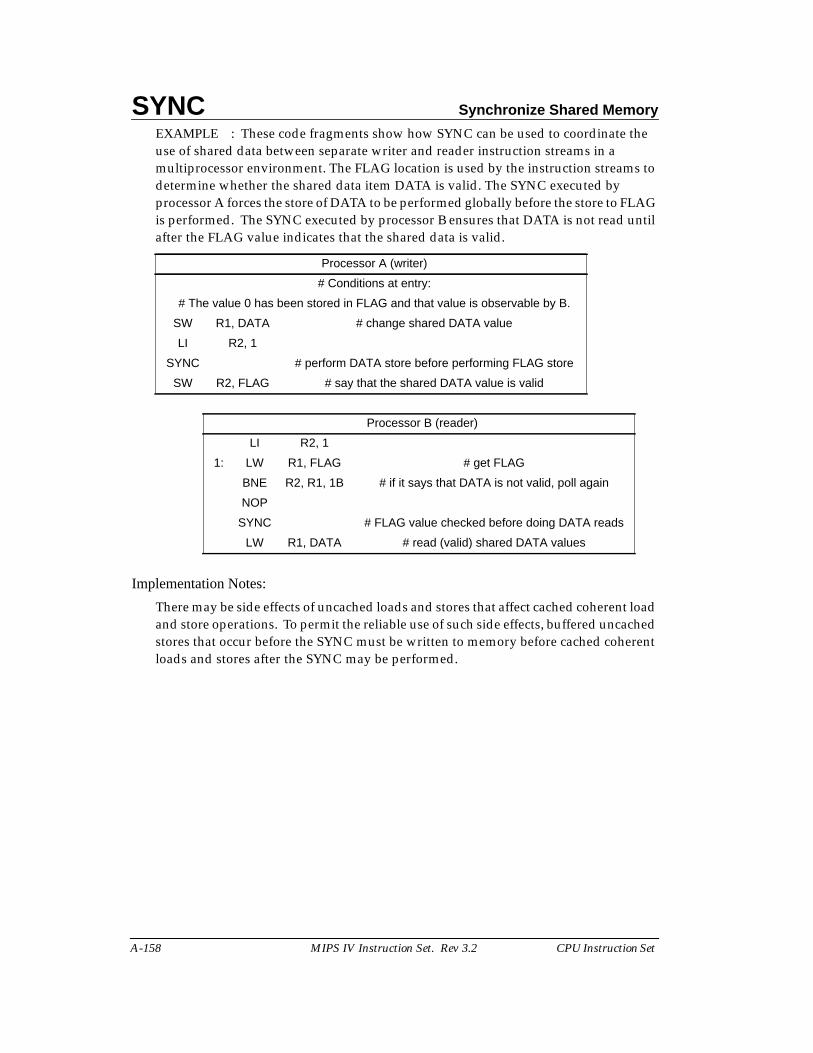
SYNC Synchronize Shared Memory
A-158 MIPS IV Instruction Set. Rev 3.2 CPU Instruction Set
EXAMPLE : These code fragments show how SYNC can be used to coordinate theuse of shared data between separate writer and reader instruction streams in amultiprocessor environment. The FLAG location is used by the instruction streams todetermine whether the shared data item DATA is valid. The SYNC executed byprocessor A forces the store of DATA to be performed globally before the store to FLAGis performed. The SYNC executed by processor B ensures that DATA is not read untilafter the FLAG value indicates that the shared data is valid.
Implementation Notes:
There may be side effects of uncached loads and stores that affect cached coherent loadand store operations. To permit the reliable use of such side effects, buffered uncachedstores that occur before the SYNC must be written to memory before cached coherentloads and stores after the SYNC may be performed.
Processor A (writer)
# Conditions at entry:
# The value 0 has been stored in FLAG and that value is observable by B.
SW R1, DATA # change shared DATA value
LI R2, 1
SYNC # perform DATA store before performing FLAG store
SW R2, FLAG # say that the shared DATA value is valid
Processor B (reader)
LI R2, 1
1: LW R1, FLAG # get FLAG
BNE R2, R1, 1B # if it says that DATA is not valid, poll again
NOP
SYNC # FLAG value checked before doing DATA reads
LW R1, DATA # read (valid) shared DATA values
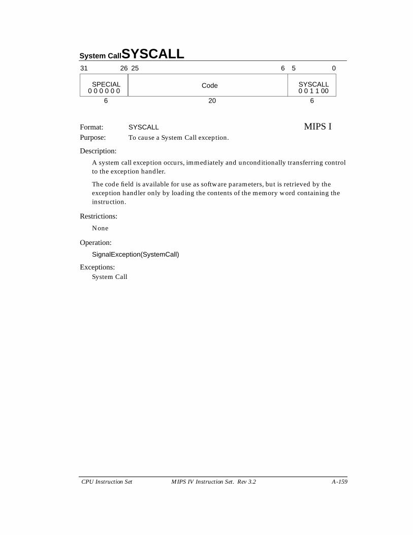
System Call SYSCALL
CPU Instruction Set MIPS IV Instruction Set. Rev 3.2 A-159
Format: SYSCALL MIPS IPurpose: To cause a System Call exception.
Description:
A system call exception occurs, immediately and unconditionally transferring controlto the exception handler.
The code field is available for use as software parameters, but is retrieved by theexception handler only by loading the contents of the memory word containing theinstruction.
Restrictions:
None
Operation:
SignalException(SystemCall)
Exceptions:System Call
31 2526
SPECIAL
6 20
Code SYSCALL
6
6 5 0
0 0 0 0 0 0 0 0 1 1 00

TEQ Trap if Equal
A-160 MIPS IV Instruction Set. Rev 3.2 CPU Instruction Set
Format: TEQ rs, rt MIPS IIPurpose: To compare GPRs and do a conditional Trap.
Description: if (rs = rt) then Trap
Compare the contents of GPR rs and GPR rt as signed integers; if GPR rs is equal toGPR rt then take a Trap exception.
The contents of the code field are ignored by hardware and may be used to encodeinformation for system software. To retrieve the information, system software mustload the instruction word from memory.
Restrictions:
None
Operation:
if GPR[rs] = GPR[rt] thenSignalException(Trap)
endif
Exceptions:Reserved InstructionTrap
31 2526 2021 1516
SPECIAL rs rt
6 5 5
code TEQ
10 6
6 5 0
0 0 0 0 0 0 1 1 0 1 0 0
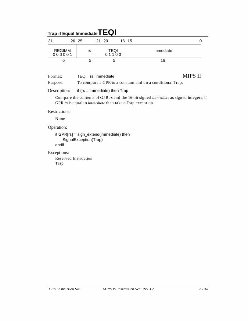
Trap if Equal Immediate TEQI
CPU Instruction Set MIPS IV Instruction Set. Rev 3.2 A-161
Format: TEQI rs, immediate MIPS IIPurpose: To compare a GPR to a constant and do a conditional Trap.
Description: if (rs = immediate) then Trap
Compare the contents of GPR rs and the 16-bit signed immediate as signed integers; ifGPR rs is equal to immediate then take a Trap exception.
Restrictions:
None
Operation:
if GPR[rs] = sign_extend(immediate) thenSignalException(Trap)
endif
Exceptions:Reserved InstructionTrap
31 2526 2021 1516
REGIMM rs
6 5 5
immediateTEQI
16
0
0 0 0 0 0 1 0 1 1 0 0
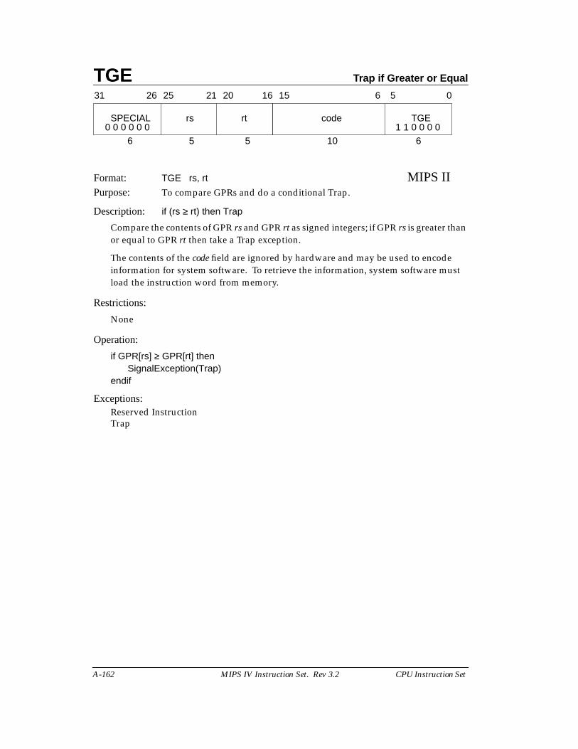
TGE Trap if Greater or Equal
A-162 MIPS IV Instruction Set. Rev 3.2 CPU Instruction Set
Format: TGE rs, rt MIPS IIPurpose: To compare GPRs and do a conditional Trap.
Description: if (rs ≥ rt) then Trap
Compare the contents of GPR rs and GPR rt as signed integers; if GPR rs is greater thanor equal to GPR rt then take a Trap exception.
The contents of the code field are ignored by hardware and may be used to encodeinformation for system software. To retrieve the information, system software mustload the instruction word from memory.
Restrictions:
None
Operation:
if GPR[rs] ≥ GPR[rt] thenSignalException(Trap)
endif
Exceptions:Reserved InstructionTrap
31 2526 2021 1516
SPECIAL rs rt
6 5 5
code TGE
10 6
6 5 0
0 0 0 0 0 0 1 1 0 0 0 0
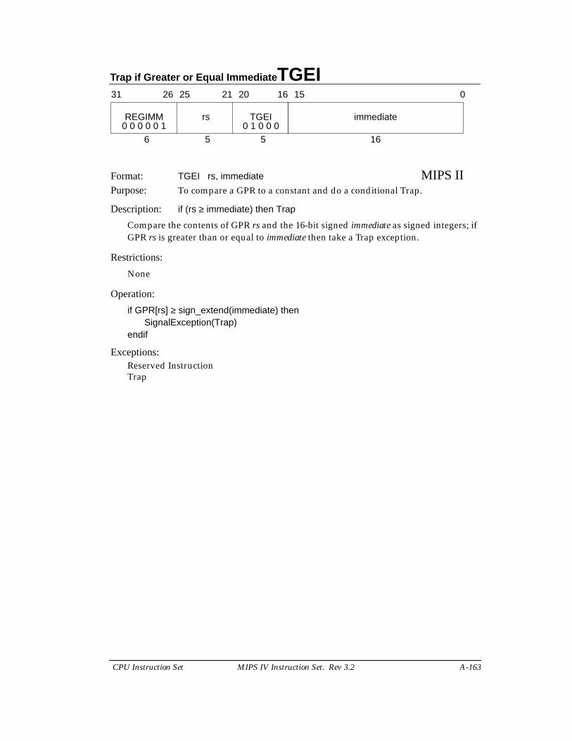
Trap if Greater or Equal Immediate TGEI
CPU Instruction Set MIPS IV Instruction Set. Rev 3.2 A-163
Format: TGEI rs, immediate MIPS IIPurpose: To compare a GPR to a constant and do a conditional Trap.
Description: if (rs ≥ immediate) then Trap
Compare the contents of GPR rs and the 16-bit signed immediate as signed integers; ifGPR rs is greater than or equal to immediate then take a Trap exception.
Restrictions:
None
Operation:
if GPR[rs] ≥ sign_extend(immediate) thenSignalException(Trap)
endif
Exceptions:Reserved InstructionTrap
31 2526 2021 1516
REGIMM rs
6 5 5
immediateTGEI
16
0
0 0 0 0 0 1 0 1 0 0 0

TGEIU Trap If Greater Or Equal Immediate Unsigned
A-164 MIPS IV Instruction Set. Rev 3.2 CPU Instruction Set
Format: TGEIU rs, immediate MIPS IIPurpose: To compare a GPR to a constant and do a conditional Trap.
Description: if (rs ≥ immediate) then Trap
Compare the contents of GPR rs and the 16-bit sign-extended immediate as unsignedintegers; if GPR rs is greater than or equal to immediate then take a Trap exception.
Because the 16-bit immediate is sign-extended before comparison, the instruction is ableto represent the smallest or largest unsigned numbers. The representable values are atthe minimum [0, 32767] or maximum [max_unsigned-32767, max_unsigned] end ofthe unsigned range.
Restrictions:
None
Operation:
if (0 || GPR[rs]) ≥ (0 || sign_extend(immediate)) thenSignalException(Trap)
endif
Exceptions:Reserved InstructionTrap
31 2526 2021 1516
REGIMM rs
6 5 5
immediateTGEIU
16
0
0 0 0 0 0 1 0 1 0 0 1
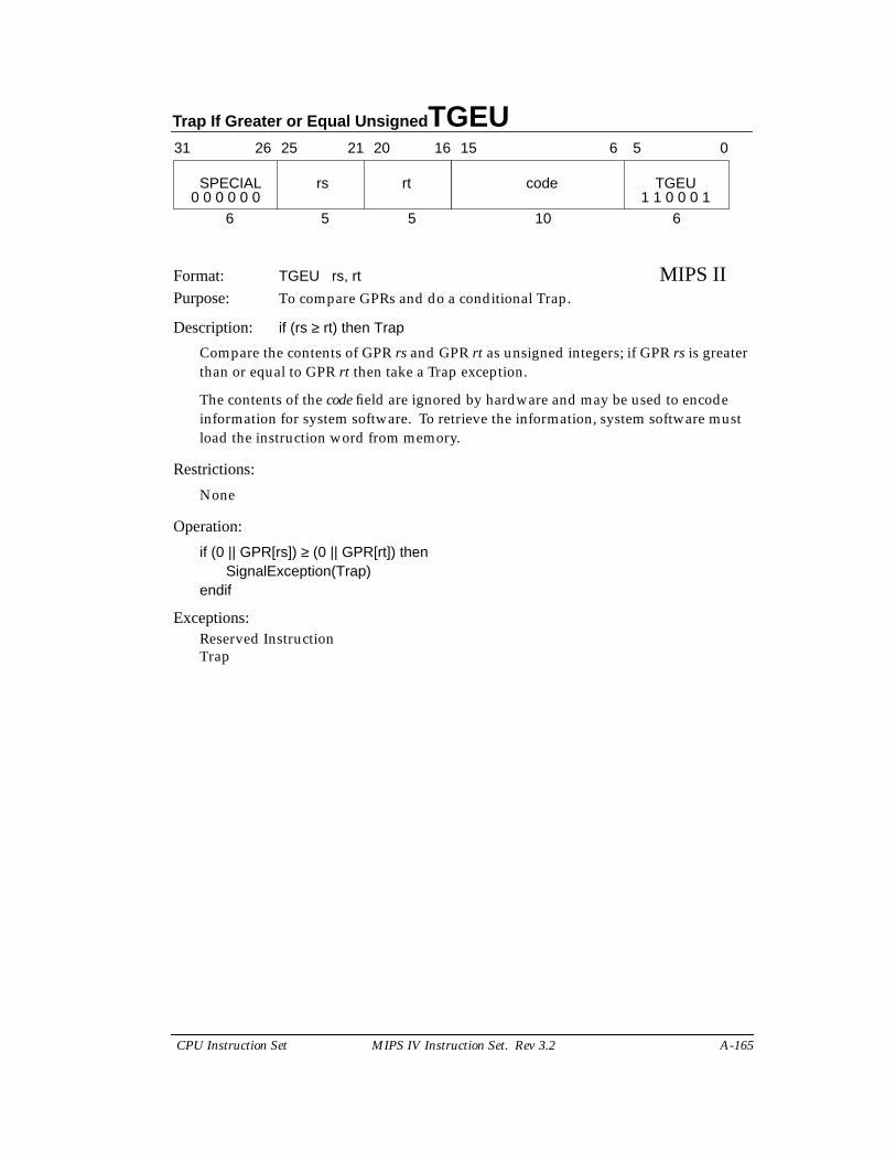
Trap If Greater or Equal Unsigned TGEU
CPU Instruction Set MIPS IV Instruction Set. Rev 3.2 A-165
Format: TGEU rs, rt MIPS IIPurpose: To compare GPRs and do a conditional Trap.
Description: if (rs ≥ rt) then Trap
Compare the contents of GPR rs and GPR rt as unsigned integers; if GPR rs is greaterthan or equal to GPR rt then take a Trap exception.
The contents of the code field are ignored by hardware and may be used to encodeinformation for system software. To retrieve the information, system software mustload the instruction word from memory.
Restrictions:
None
Operation:
if (0 || GPR[rs]) ≥ (0 || GPR[rt]) thenSignalException(Trap)
endif
Exceptions:Reserved InstructionTrap
31 2526 2021 1516
SPECIAL rs rt
6 5 5
code TGEU
10 6
6 5 0
0 0 0 0 0 0 1 1 0 0 0 1

TLT Trap if Less Than
A-166 MIPS IV Instruction Set. Rev 3.2 CPU Instruction Set
Format: TLT rs, rt MIPS IIPurpose: To compare GPRs and do a conditional Trap.
Description: if (rs < rt) then Trap
Compare the contents of GPR rs and GPR rt as signed integers; if GPR rs is less thanGPR rt then take a Trap exception.
The contents of the code field are ignored by hardware and may be used to encodeinformation for system software. To retrieve the information, system software mustload the instruction word from memory.
Restrictions:
None
Operation:
if GPR[rs] < GPR[rt] thenSignalException(Trap)
endif
Exceptions:Reserved InstructionTrap
31 2526 2021 1516
SPECIAL rs rt
6 5 5
code TLT
10 6
6 5 0
0 0 0 0 0 0 1 1 0 0 1 0
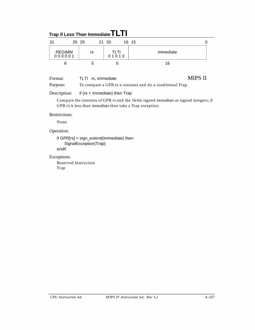
Trap if Less Than Immediate TLTI
CPU Instruction Set MIPS IV Instruction Set. Rev 3.2 A-167
Format: TLTI rs, immediate MIPS IIPurpose: To compare a GPR to a constant and do a conditional Trap.
Description: if (rs < immediate) then Trap
Compare the contents of GPR rs and the 16-bit signed immediate as signed integers; ifGPR rs is less than immediate then take a Trap exception.
Restrictions:
None
Operation:
if GPR[rs] < sign_extend(immediate) thenSignalException(Trap)
endif
Exceptions:Reserved InstructionTrap
31 2526 2021 1516
REGIMM rs
6 5 5
immediateTLTI
16
0
0 0 0 0 0 1 0 1 0 1 0
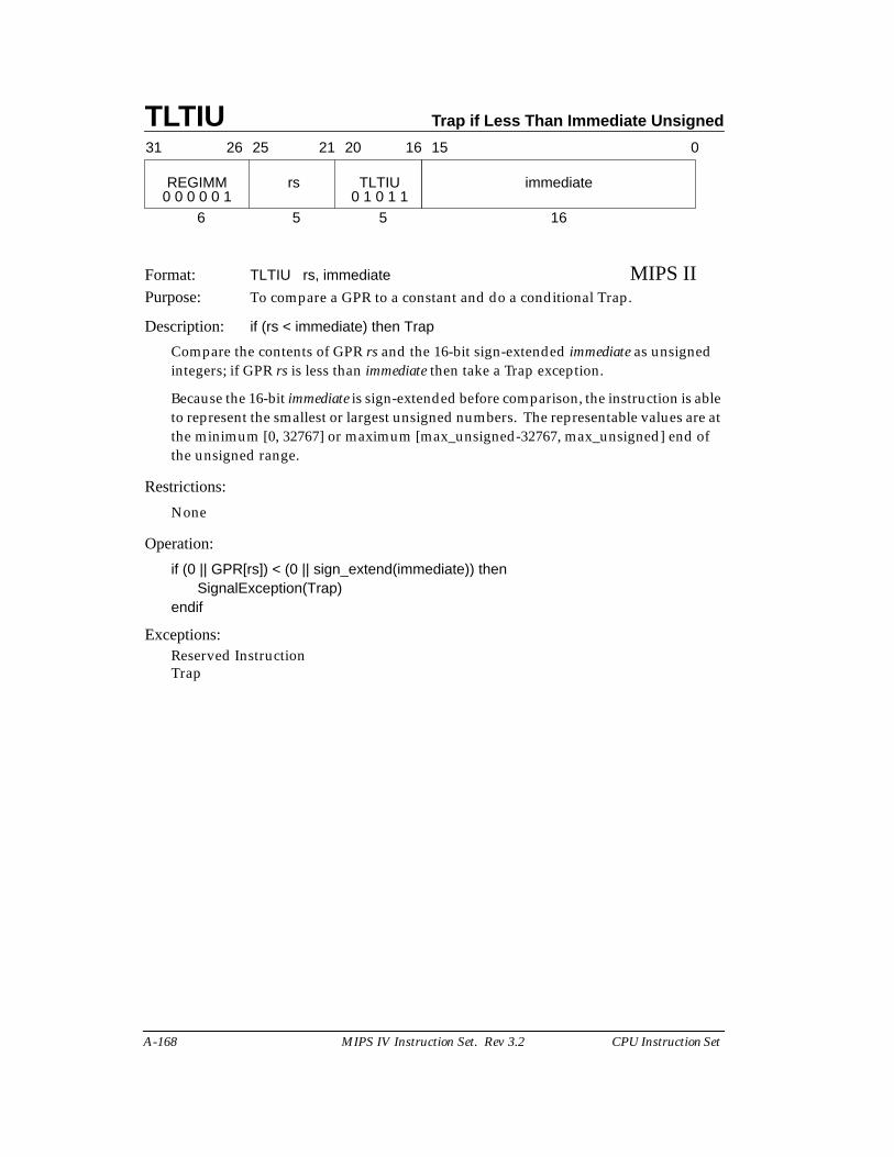
TLTIU Trap if Less Than Immediate Unsigned
A-168 MIPS IV Instruction Set. Rev 3.2 CPU Instruction Set
Format: TLTIU rs, immediate MIPS IIPurpose: To compare a GPR to a constant and do a conditional Trap.
Description: if (rs < immediate) then Trap
Compare the contents of GPR rs and the 16-bit sign-extended immediate as unsignedintegers; if GPR rs is less than immediate then take a Trap exception.
Because the 16-bit immediate is sign-extended before comparison, the instruction is ableto represent the smallest or largest unsigned numbers. The representable values are atthe minimum [0, 32767] or maximum [max_unsigned-32767, max_unsigned] end ofthe unsigned range.
Restrictions:
None
Operation:
if (0 || GPR[rs]) < (0 || sign_extend(immediate)) thenSignalException(Trap)
endif
Exceptions:Reserved InstructionTrap
31 2526 2021 1516
REGIMM rs
6 5 5
immediateTLTIU
16
0
0 0 0 0 0 1 0 1 0 1 1
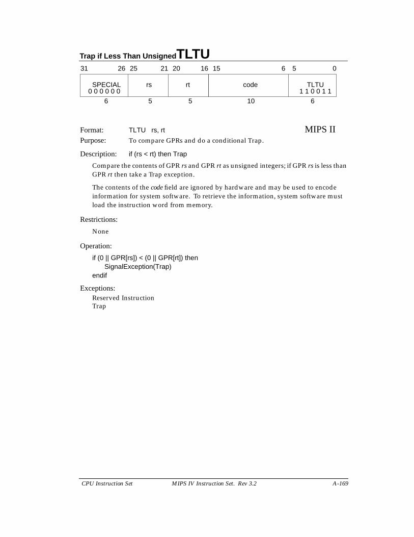
Trap if Less Than Unsigned TLTU
CPU Instruction Set MIPS IV Instruction Set. Rev 3.2 A-169
Format: TLTU rs, rt MIPS IIPurpose: To compare GPRs and do a conditional Trap.
Description: if (rs < rt) then Trap
Compare the contents of GPR rs and GPR rt as unsigned integers; if GPR rs is less thanGPR rt then take a Trap exception.
The contents of the code field are ignored by hardware and may be used to encodeinformation for system software. To retrieve the information, system software mustload the instruction word from memory.
Restrictions:
None
Operation:
if (0 || GPR[rs]) < (0 || GPR[rt]) thenSignalException(Trap)
endif
Exceptions:Reserved InstructionTrap
31 2526 2021 1516
SPECIAL rs rt
6 5 5
code TLTU
10 6
6 5 0
0 0 0 0 0 0 1 1 0 0 1 1

TNE Trap if Not Equal
A-170 MIPS IV Instruction Set. Rev 3.2 CPU Instruction Set
Format: TNE rs, rt MIPS IIPurpose: To compare GPRs and do a conditional Trap.
Description: if (rs ≠ rt) then Trap
Compare the contents of GPR rs and GPR rt as signed integers; if GPR rs is not equalto GPR rt then take a Trap exception.
The contents of the code field are ignored by hardware and may be used to encodeinformation for system software. To retrieve the information, system software mustload the instruction word from memory.
Restrictions:
None
Operation:
if GPR[rs] ≠ GPR[rt] thenSignalException(Trap)
endif
Exceptions:Reserved InstructionTrap
31 2526 2021 1516
SPECIAL rs rt
6 5 5
code TNE
10 6
6 5 0
0 0 0 0 0 0 1 1 0 1 1 0
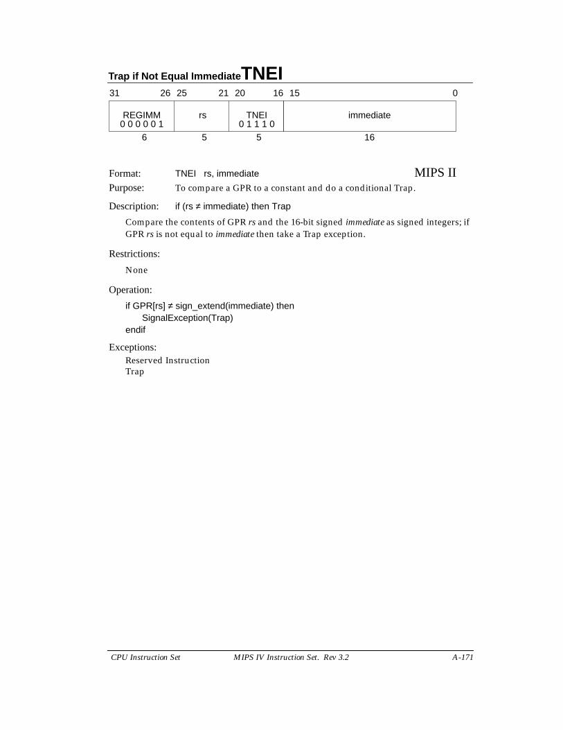
Trap if Not Equal Immediate TNEI
CPU Instruction Set MIPS IV Instruction Set. Rev 3.2 A-171
Format: TNEI rs, immediate MIPS IIPurpose: To compare a GPR to a constant and do a conditional Trap.
Description: if (rs ≠ immediate) then Trap
Compare the contents of GPR rs and the 16-bit signed immediate as signed integers; ifGPR rs is not equal to immediate then take a Trap exception.
Restrictions:
None
Operation:
if GPR[rs] ≠ sign_extend(immediate) thenSignalException(Trap)
endif
Exceptions:Reserved InstructionTrap
31 2526 2021 1516
REGIMM rs
6 5 5
immediateTNEI
16
0
0 0 0 0 0 1 0 1 1 1 0
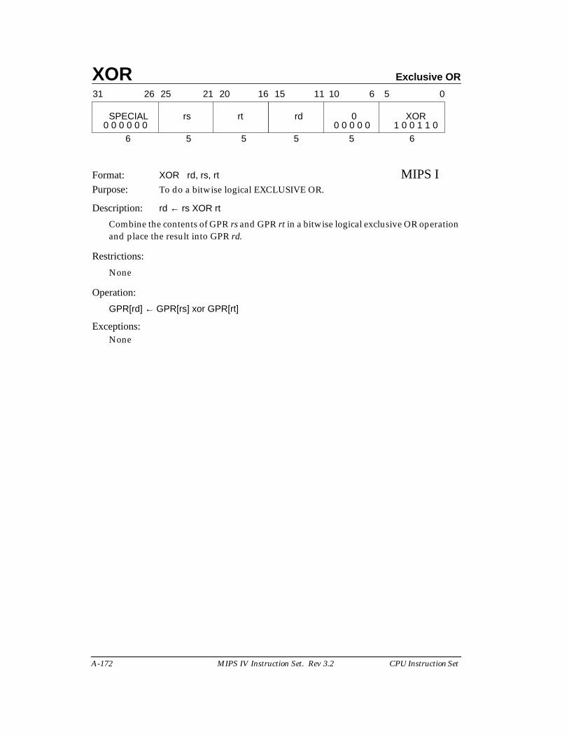
XOR Exclusive OR
A-172 MIPS IV Instruction Set. Rev 3.2 CPU Instruction Set
Format: XOR rd, rs, rt MIPS IPurpose: To do a bitwise logical EXCLUSIVE OR.
Description: rd ← rs XOR rt
Combine the contents of GPR rs and GPR rt in a bitwise logical exclusive OR operationand place the result into GPR rd.
Restrictions:
None
Operation:
GPR[rd] ← GPR[rs] xor GPR[rt]
Exceptions:None
31 2526 2021 1516
SPECIAL rs rt
6 5 5
rd 0 XOR
5 5 6
11 10 6 5 0
0 0 0 0 0 0 1 0 0 1 1 00 0 0 0 0
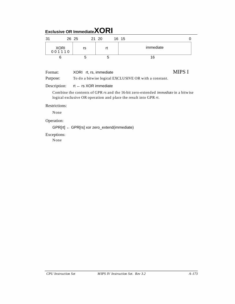
Exclusive OR Immediate XORI
CPU Instruction Set MIPS IV Instruction Set. Rev 3.2 A-173
Format: XORI rt, rs, immediate MIPS IPurpose: To do a bitwise logical EXCLUSIVE OR with a constant.
Description: rt ← rs XOR immediate
Combine the contents of GPR rs and the 16-bit zero-extended immediate in a bitwiselogical exclusive OR operation and place the result into GPR rt.
Restrictions:
None
Operation:
GPR[rt] ← GPR[rs] xor zero_extend(immediate)
Exceptions:None
31 2526 2021 1516 0
XORI rs rt immediate
6 5 5 160 0 1 1 1 0
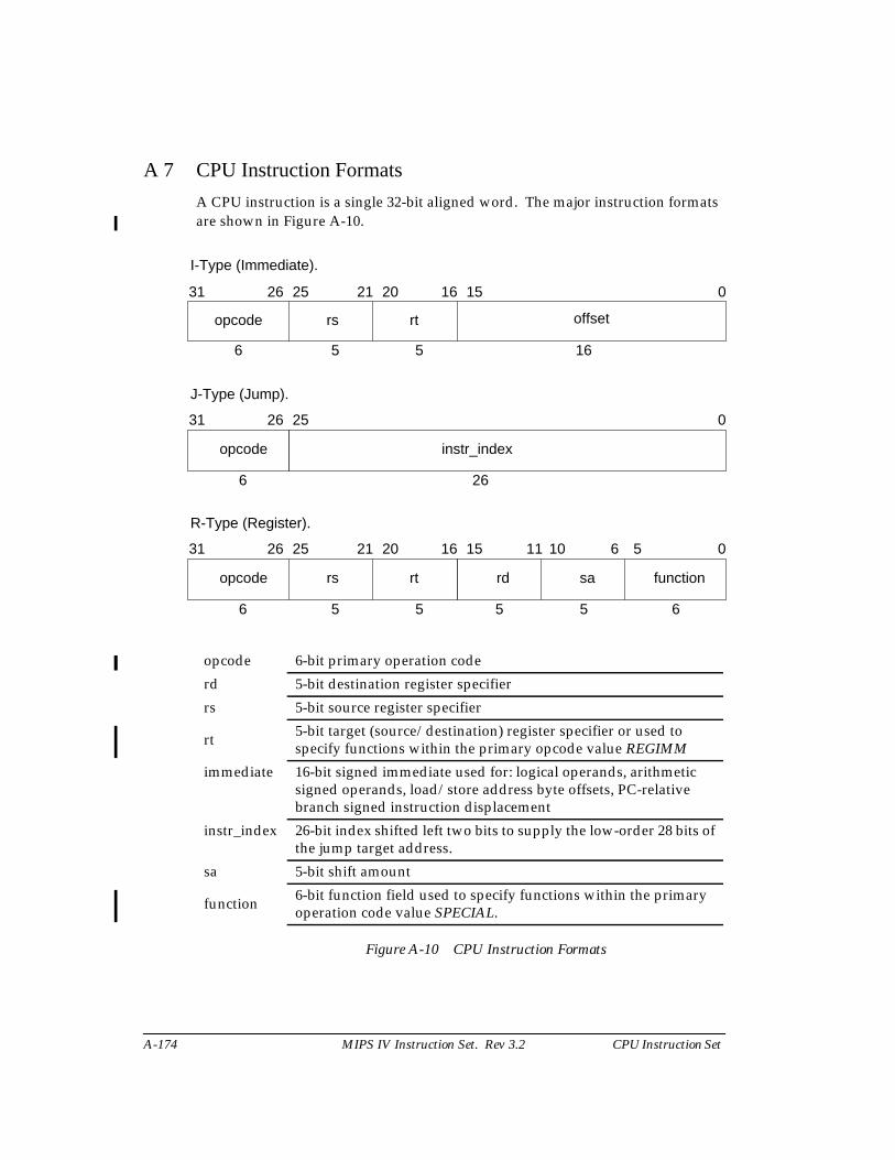
A-174 MIPS IV Instruction Set. Rev 3.2 CPU Instruction Set
A
A 7 CPU Instruction Formats
A CPU instruction is a single 32-bit aligned word. The major instruction formatsare shown in Figure A-10.
Figure A-10 CPU Instruction Formats
opcode 6-bit primary operation code
rd 5-bit destination register specifier
rs 5-bit source register specifier
rt 5-bit target (source/destination) register specifier or used tospecify functions within the primary opcode value REGIMM
immediate 16-bit signed immediate used for: logical operands, arithmeticsigned operands, load/store address byte offsets, PC-relativebranch signed instruction displacement
instr_index 26-bit index shifted left two bits to supply the low-order 28 bits ofthe jump target address.
sa 5-bit shift amount
function 6-bit function field used to specify functions within the primaryoperation code value SPECIAL.
I-Type (Immediate).
31 2526 2021 1516 0
opcode rs rt offset
6 5 5 16
J-Type (Jump).
31 2526
opcode
6
0
instr_index
26
R-Type (Register).
31 2526 2021 1516
opcode rs rt
6 5 5
rd sa function
5 5 6
11 10 6 5 0
CPU Instruction Set MIPS IV Instruction Set. Rev 3.2 A-175
A 8 CPU Instruction Encoding
This section describes the encoding of user-level, i.e. non-privileged, CPUinstructions for the four levels of the MIPS architecture, MIPS I through MIPS IV. Eacharchitecture level includes the instructions in the previous level;† MIPS IV includes allinstructions in MIPS I, MIPS II, and MIPS III. This section presents eight different views ofthe instruction encoding.
• Separate encoding tables for each architecture level.
• A MIPS IV encoding table showing the architecture level at which eachopcode was originally defined and subsequently modified (if modified).
• Separate encoding tables for each architecture revision showing thechanges made during that revision.
A 8.1 Instruction Decode
Instruction field names are printed in bold in this section.
The primary opcode field is decoded first. Most opcode values completelyspecify an instruction that has an immediate value or offset. Opcode values that do notspecify an instruction specify an instruction class. Instructions within a class are furtherspecified by values in other fields. The opcode values SPECIAL and REGIMM specifyinstruction classes. The COP0, COP1, COP2, COP3, and COP1X instruction classes are notCPU instructions; they are discussed in section A 8.3.
A 8.1.1 SPECIAL Instruction Class
The opcode =SPECIAL instruction class encodes 3-register computationalinstructions, jump register, and some special purpose instructions. The class is furtherdecoded by examining the format field. The format values fully specify the CPUinstructions; the MOVCI instruction class is not a CPU instruction class.
A 8.1.2 REGIMM Instruction Class
The opcode =REGIMM instruction class encodes conditional branch and trapimmediate instructions. The class is further decode, and the instructions fully specified, byexamining the rt field.
A 8.2 Instruction Subsets of MIPS III and MIPS IV Processors.
MIPS III processors, such as the R4000, R4200, R4300, R4400, and R4600, have aprocessor mode in which only the MIPS II instructions are valid. The MIPS II encodingtable describes the MIPS II-only mode except that the Coprocessor 3 instructions (COP3,LWC3, SWC3, LDC3, SDC3) are not available and cause a Reserved Instruction exception.
† An exception to this rule is that the reserved, but never implemented, Coprocessor 3instructions were removed or changed to another use starting in MIPS III.
A-176 MIPS IV Instruction Set. Rev 3.2 CPU Instruction Set
MIPS IV processors, such as the R8000 and R10000, have processor modes in whichonly the MIPS II or MIPS III instructions are valid. The MIPS II encoding table describesthe MIPS II-only mode except that the Coprocessor 3 instructions (COP3, LWC3, SWC3,LDC3, SDC3) are not available and cause a Reserved Instruction exception. The MIPS IIIencoding table describes the MIPS III-only mode.
A 8.3 Non-CPU Instructions in the Tables
The encoding tables show all values for the field they describe and by doing thisthey include some entries that are not user-level CPU instructions. The primary opcodetable includes coprocessor instruction classes (COP0, COP1, COP2, COP3/COP1X) andcoprocessor load/store instructions (LWCx, SWCx, LDCx, SDCx for x=1, 2, or 3). Theopcode =SPECIAL + function =MOVCI instruction class is an FPU instruction.
A 8.3.1 Coprocessor 0 - COP0
COP0 encodes privileged instructions for Coprocessor 0, the System ControlCoprocessor. The definition of the System Control Coprocessor is processor-specific andfurther information on these instructions are not included in this document.
A 8.3.2 Coprocessor 1 - COP1, COP1X, MOVCI, and CP1 load/store.
Coprocessor 1 is the floating-point unit in the MIPS architecture. COP1, COP1X,and the (opcode =SPECIAL + function =MOVCI) instruction classes encode floating-pointinstructions. LWC1, SWC1, LDC1, and SDC1 are floating-point loads and stores. The FPUinstruction encoding is documented in section B.12.
A 8.3.3 Coprocessor 2 - COP2 and CP2 load/store.
Coprocessor 2 is optional and implementation-specific. No standard processorfrom MIPS has implemented coprocessor 2, but MIPS’ semiconductor licensees may haveimplemented it in a product based on one of the standard MIPS processors. At this timethe standard processors are: R2000, R3000, R4000, R4200, R4300, R4400, R4600, R6000,R8000, and R10000.
A 8.3.4 Coprocessor 3 - COP3 and CP3 load/store.
Coprocessor 3 is optional and implementation-specific in the MIPS I and MIPS IIarchitecture levels. It was removed from MIPS III and later architecture levels. Note thatin MIPS IV the COP3 primary opcode was reused for the COP1X instruction class. Nostandard processor from MIPS has implemented coprocessor 2, but MIPS’ semiconductorlicensees may have implemented it in a product based on one of the standard MIPSprocessors. At this time the standard processors are: R2000, R3000, R4000, R4200, R4300,R4400, R4600, R6000, R8000, and R10000.
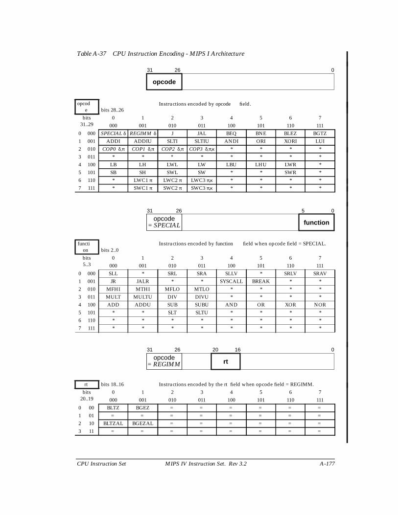
CPU Instruction Set MIPS IV Instruction Set. Rev 3.2 A-177
Table A-37 CPU Instruction Encoding - MIPS I Architecture
opcode bits 28..26
Instructions encoded by opcode field.
bits31..29
0 1 2 3 4 5 6 7000 001 010 011 100 101 110 111
0 000 SPECIAL δ REGIMM δ J JAL BEQ BNE BLEZ BGTZ1 001 ADDI ADDIU SLTI SLTIU ANDI ORI XORI LUI2 010 COP0 δ,π COP1 δ,π COP2 δ,π COP3 δ,π,κ * * * *3 011 * * ∗ * * * * *4 100 LB LH LWL LW LBU LHU LWR *5 101 SB SH SWL SW * * SWR *6 110 * LWC1 π LWC2 π LWC3 π,κ * * * *7 111 * SWC1 π SWC2 π SWC3 π,κ * * * *
function bits 2..0
Instructions encoded by function field when opcode field = SPECIAL.
bits5..3
0 1 2 3 4 5 6 7000 001 010 011 100 101 110 111
0 000 SLL * SRL SRA SLLV * SRLV SRAV1 001 JR JALR * * SYSCALL BREAK * *2 010 MFHI MTHI MFLO MTLO * * * *3 011 MULT MULTU DIV DIVU * * * *4 100 ADD ADDU SUB SUBU AND OR XOR NOR5 101 * * SLT SLTU * * * *6 110 * * * * * * * *7 111 * * * * * * * *
rt bits 18..16 Instructions encoded by the rt field when opcode field = REGIMM.bits
20..190 1 2 3 4 5 6 7
000 001 010 011 100 101 110 1110 00 BLTZ BGEZ = = = = = =
1 01 = = = = = = = =
2 10 BLTZAL BGEZAL = = = = = =
3 11 = = = = = = = =
31 26
opcode
0
31 26
opcodefunction
5 0
= SPECIAL
31 26 20 16 0
opcodert= REGIMM
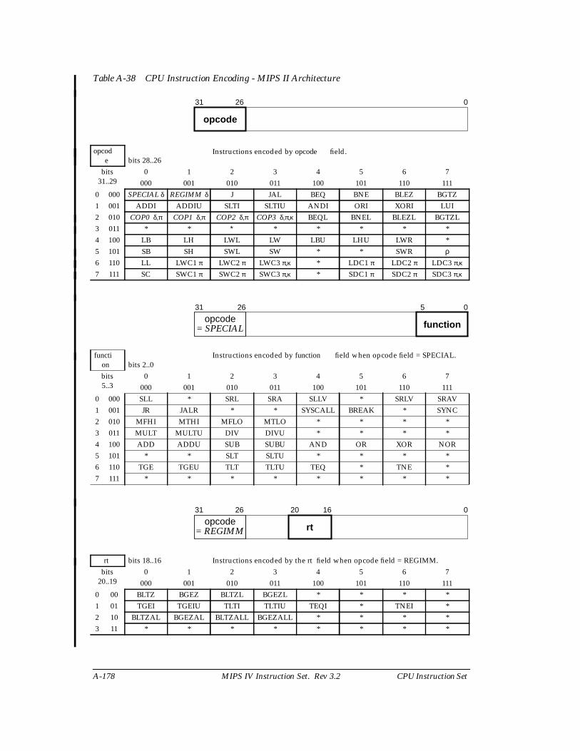
A-178 MIPS IV Instruction Set. Rev 3.2 CPU Instruction Set
Table A-38 CPU Instruction Encoding - MIPS II Architecture
opcode bits 28..26
Instructions encoded by opcode field.
bits31..29
0 1 2 3 4 5 6 7000 001 010 011 100 101 110 111
0 000 SPECIAL δ REGIMM δ J JAL BEQ BNE BLEZ BGTZ1 001 ADDI ADDIU SLTI SLTIU ANDI ORI XORI LUI2 010 COP0 δ,π COP1 δ,π COP2 δ,π COP3 δ,π,κ BEQL BNEL BLEZL BGTZL3 011 * * ∗ * * * * *4 100 LB LH LWL LW LBU LHU LWR *5 101 SB SH SWL SW * * SWR ρ6 110 LL LWC1 π LWC2 π LWC3 π,κ * LDC1 π LDC2 π LDC3 π,κ
7 111 SC SWC1 π SWC2 π SWC3 π,κ * SDC1 π SDC2 π SDC3 π,κ
function bits 2..0
Instructions encoded by function field when opcode field = SPECIAL.
bits5..3
0 1 2 3 4 5 6 7000 001 010 011 100 101 110 111
0 000 SLL * SRL SRA SLLV * SRLV SRAV1 001 JR JALR * * SYSCALL BREAK * SYNC2 010 MFHI MTHI MFLO MTLO * * * *3 011 MULT MULTU DIV DIVU * * * *4 100 ADD ADDU SUB SUBU AND OR XOR NOR5 101 * * SLT SLTU * * * *6 110 TGE TGEU TLT TLTU TEQ * TNE *7 111 * * * * * * * *
rt bits 18..16 Instructions encoded by the rt field when opcode field = REGIMM.bits
20..190 1 2 3 4 5 6 7
000 001 010 011 100 101 110 1110 00 BLTZ BGEZ BLTZL BGEZL * * * *1 01 TGEI TGEIU TLTI TLTIU TEQI * TNEI *2 10 BLTZAL BGEZAL BLTZALL BGEZALL * * * *3 11 * * * * * * * *
31 26
opcode
0
31 26
opcodefunction
5 0
= SPECIAL
31 26 20 16 0
opcodert= REGIMM
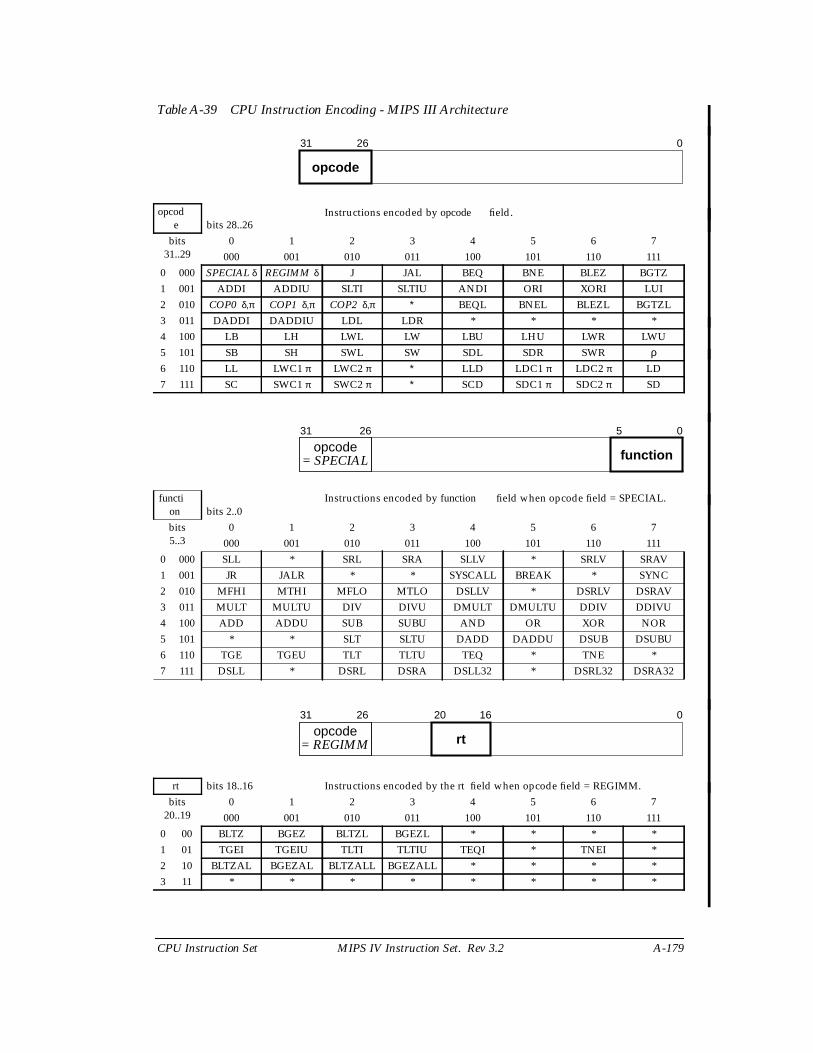
CPU Instruction Set MIPS IV Instruction Set. Rev 3.2 A-179
Table A-39 CPU Instruction Encoding - MIPS III Architecture
opcode bits 28..26
Instructions encoded by opcode field.
bits31..29
0 1 2 3 4 5 6 7000 001 010 011 100 101 110 111
0 000 SPECIAL δ REGIMM δ J JAL BEQ BNE BLEZ BGTZ1 001 ADDI ADDIU SLTI SLTIU ANDI ORI XORI LUI2 010 COP0 δ,π COP1 δ,π COP2 δ,π ∗ BEQL BNEL BLEZL BGTZL3 011 DADDI DADDIU LDL LDR * * * *4 100 LB LH LWL LW LBU LHU LWR LWU5 101 SB SH SWL SW SDL SDR SWR ρ6 110 LL LWC1 π LWC2 π ∗ LLD LDC1 π LDC2 π LD7 111 SC SWC1 π SWC2 π ∗ SCD SDC1 π SDC2 π SD
function bits 2..0
Instructions encoded by function field when opcode field = SPECIAL.
bits5..3
0 1 2 3 4 5 6 7000 001 010 011 100 101 110 111
0 000 SLL * SRL SRA SLLV * SRLV SRAV1 001 JR JALR * * SYSCALL BREAK * SYNC2 010 MFHI MTHI MFLO MTLO DSLLV * DSRLV DSRAV3 011 MULT MULTU DIV DIVU DMULT DMULTU DDIV DDIVU4 100 ADD ADDU SUB SUBU AND OR XOR NOR5 101 * * SLT SLTU DADD DADDU DSUB DSUBU6 110 TGE TGEU TLT TLTU TEQ * TNE *7 111 DSLL * DSRL DSRA DSLL32 * DSRL32 DSRA32
rt bits 18..16 Instructions encoded by the rt field when opcode field = REGIMM.bits
20..190 1 2 3 4 5 6 7
000 001 010 011 100 101 110 1110 00 BLTZ BGEZ BLTZL BGEZL * * * *1 01 TGEI TGEIU TLTI TLTIU TEQI * TNEI *2 10 BLTZAL BGEZAL BLTZALL BGEZALL * * * *3 11 * * * * * * * *
31 26
opcode
0
31 26
opcodefunction
5 0
= SPECIAL
31 26 20 16 0
opcodert= REGIMM
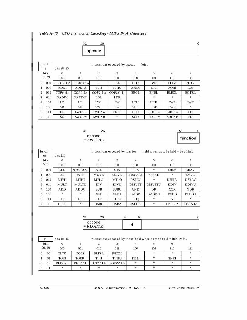
A-180 MIPS IV Instruction Set. Rev 3.2 CPU Instruction Set
Table A-40 CPU Instruction Encoding - MIPS IV Architecture
opcode bits 28..26
Instructions encoded by opcode field.
bits31..29
0 1 2 3 4 5 6 7000 001 010 011 100 101 110 111
0 000 SPECIAL δ REGIMM δ J JAL BEQ BNE BLEZ BGTZ1 001 ADDI ADDIU SLTI SLTIU ANDI ORI XORI LUI2 010 COP0 δ,π COP1 δ,π COP2 δ,π COP1X δ,π BEQL BNEL BLEZL BGTZL3 011 DADDI DADDIU LDL LDR * * *4 100 LB LH LWL LW LBU LHU LWR LWU5 101 SB SH SWL SW SDL SDR SWR ρ6 110 LL LWC1 π LWC2 π PREF LLD LDC1 π LDC2 π LD7 111 SC SWC1 π SWC2 π ∗ SCD SDC1 π SDC2 π SD
function bits 2..0
Instructions encoded by function field when opcode field = SPECIAL.
bits5..3
0 1 2 3 4 5 6 7000 001 010 011 100 101 110 111
0 000 SLL MOVCI δ,µ SRL SRA SLLV * SRLV SRAV1 001 JR JALR MOVZ MOVN SYSCALL BREAK * SYNC2 010 MFHI MTHI MFLO MTLO DSLLV * DSRLV DSRAV3 011 MULT MULTU DIV DIVU DMULT DMULTU DDIV DDIVU4 100 ADD ADDU SUB SUBU AND OR XOR NOR5 101 * * SLT SLTU DADD DADDU DSUB DSUBU6 110 TGE TGEU TLT TLTU TEQ * TNE *7 111 DSLL * DSRL DSRA DSLL32 * DSRL32 DSRA32
rt bits 18..16 Instructions encoded by the rt field when opcode field = REGIMM.bits
20..190 1 2 3 4 5 6 7
000 001 010 011 100 101 110 1110 00 BLTZ BGEZ BLTZL BGEZL * * * *1 01 TGEI TGEIU TLTI TLTIU TEQI * TNEI *2 10 BLTZAL BGEZAL BLTZALL BGEZALL * * * *3 11 * * * * * * * *
31 26
opcode
0
31 26
opcodefunction
5 0
= SPECIAL
31 26 20 16 0
opcodert= REGIMM

CPU Instruction Set MIPS IV Instruction Set. Rev 3.2 A-181
Table A-41 Architecture Level in Which CPU Instructions are Defined or Extended.
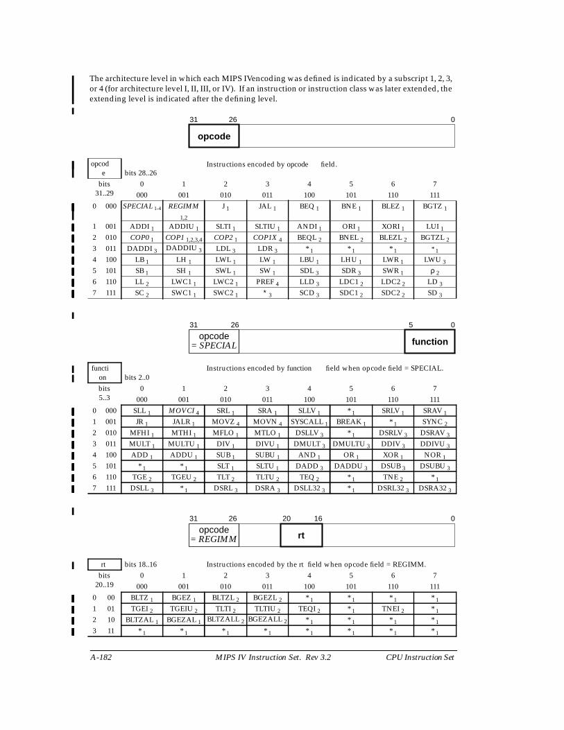
A-182 MIPS IV Instruction Set. Rev 3.2 CPU Instruction Set
The architecture level in which each MIPS IVencoding was defined is indicated by a subscript 1, 2, 3,or 4 (for architecture level I, II, III, or IV). If an instruction or instruction class was later extended, theextending level is indicated after the defining level.
opcode bits 28..26
Instructions encoded by opcode field.
bits31..29
0 1 2 3 4 5 6 7000 001 010 011 100 101 110 111
0 000 SPECIAL 1-4 REGIMM
1,2
J 1 JAL 1 BEQ 1 BNE 1 BLEZ 1 BGTZ 1
1 001 ADDI 1 ADDIU 1 SLTI 1 SLTIU 1 ANDI 1 ORI 1 XORI 1 LUI 1
2 010 COP0 1 COP1 1,2,3,4 COP2 1 COP1X 4 BEQL 2 BNEL 2 BLEZL 2 BGTZL 2
3 011 DADDI 3 DADDIU 3 LDL 3 LDR 3 * 1 * 1 * 1 * 1
4 100 LB 1 LH 1 LWL 1 LW 1 LBU 1 LHU 1 LWR 1 LWU 3
5 101 SB 1 SH 1 SWL 1 SW 1 SDL 3 SDR 3 SWR 1 ρ 2
6 110 LL 2 LWC1 1 LWC2 1 PREF 4 LLD 3 LDC1 2 LDC2 2 LD 3
7 111 SC 2 SWC1 1 SWC2 1 ∗ 3 SCD 3 SDC1 2 SDC2 2 SD 3
function bits 2..0
Instructions encoded by function field when opcode field = SPECIAL.
bits5..3
0 1 2 3 4 5 6 7000 001 010 011 100 101 110 111
0 000 SLL 1 MOVCI 4 SRL 1 SRA 1 SLLV 1 * 1 SRLV 1 SRAV 1
1 001 JR 1 JALR 1 MOVZ 4 MOVN 4 SYSCALL 1 BREAK 1 * 1 SYNC 2
2 010 MFHI 1 MTHI 1 MFLO 1 MTLO 1 DSLLV 3 * 1 DSRLV 3 DSRAV 3
3 011 MULT 1 MULTU 1 DIV 1 DIVU 1 DMULT 3 DMULTU 3 DDIV 3 DDIVU 3
4 100 ADD 1 ADDU 1 SUB 1 SUBU 1 AND 1 OR 1 XOR 1 NOR 1
5 101 * 1 * 1 SLT 1 SLTU 1 DADD 3 DADDU 3 DSUB 3 DSUBU 3
6 110 TGE 2 TGEU 2 TLT 2 TLTU 2 TEQ 2 * 1 TNE 2 * 1
7 111 DSLL 3 * 1 DSRL 3 DSRA 3 DSLL32 3 * 1 DSRL32 3 DSRA32 3
rt bits 18..16 Instructions encoded by the rt field when opcode field = REGIMM.bits
20..190 1 2 3 4 5 6 7
000 001 010 011 100 101 110 1110 00 BLTZ 1 BGEZ 1 BLTZL 2 BGEZL 2 * 1 * 1 * 1 * 1
1 01 TGEI 2 TGEIU 2 TLTI 2 TLTIU 2 TEQI 2 * 1 TNEI 2 * 1
2 10 BLTZAL 1 BGEZAL 1 BLTZALL 2 BGEZALL 2 * 1 * 1 * 1 * 1
3 11 * 1 * 1 * 1 * 1 * 1 * 1 * 1 * 1
31 26
opcode
0
31 26
opcodefunction
5 0
= SPECIAL
31 26 20 16 0
opcodert= REGIMM

CPU Instruction Set MIPS IV Instruction Set. Rev 3.2 A-183
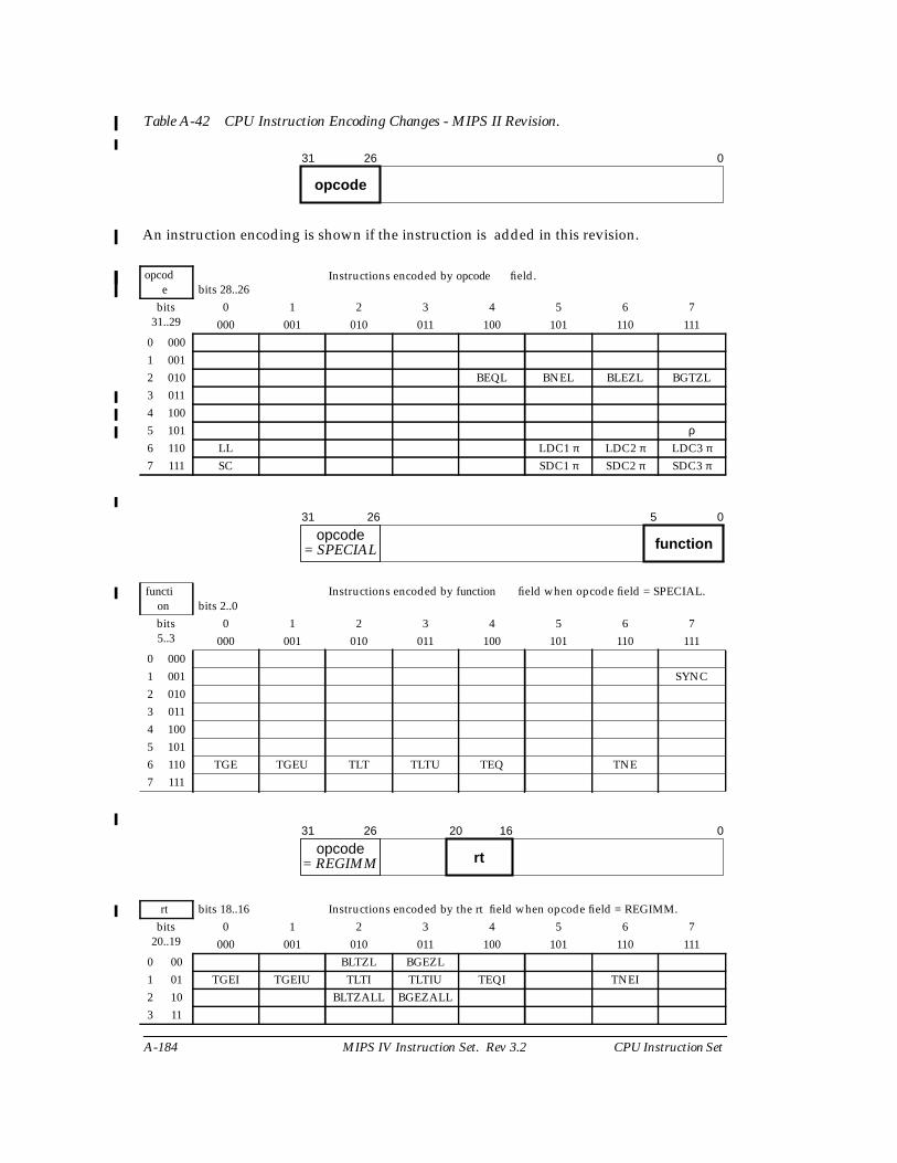
A-184 MIPS IV Instruction Set. Rev 3.2 CPU Instruction Set
Table A-42 CPU Instruction Encoding Changes - MIPS II Revision.
An instruction encoding is shown if the instruction is added in this revision.
opcode bits 28..26
Instructions encoded by opcode field.
bits31..29
0 1 2 3 4 5 6 7000 001 010 011 100 101 110 111
0 0001 0012 010 BEQL BNEL BLEZL BGTZL3 0114 1005 101 ρ6 110 LL LDC1 π LDC2 π LDC3 π
7 111 SC SDC1 π SDC2 π SDC3 π
function bits 2..0
Instructions encoded by function field when opcode field = SPECIAL.
bits5..3
0 1 2 3 4 5 6 7000 001 010 011 100 101 110 111
0 0001 001 SYNC2 0103 0114 1005 1016 110 TGE TGEU TLT TLTU TEQ TNE7 111
rt bits 18..16 Instructions encoded by the rt field when opcode field = REGIMM.bits
20..190 1 2 3 4 5 6 7
000 001 010 011 100 101 110 1110 00 BLTZL BGEZL1 01 TGEI TGEIU TLTI TLTIU TEQI TNEI2 10 BLTZALL BGEZALL3 11
31 26
opcode
0
31 26
opcodefunction
5 0
= SPECIAL
31 26 20 16 0
opcodert= REGIMM

CPU Instruction Set MIPS IV Instruction Set. Rev 3.2 A-185

A-186 MIPS IV Instruction Set. Rev 3.2 CPU Instruction Set
Table A-43 CPU Instruction Encoding Changes - MIPS III Revision.
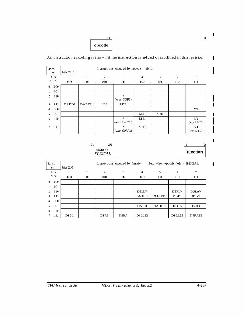
CPU Instruction Set MIPS IV Instruction Set. Rev 3.2 A-187
An instruction encoding is shown if the instruction is added or modified in this revision.
opcode bits 28..26
Instructions encoded by opcode field.
bits31..29
0 1 2 3 4 5 6 7000 001 010 011 100 101 110 111
0 0001 0012 010 *
(was COP3)3 011 DADDI DADDIU LDL LDR4 100 LWU5 101 SDL SDR6 110 *
(was LWC3 )LLD LD
(was LDC3)
7 111 *(was SWC3)
SCD SD(was SDC3)
function bits 2..0
Instructions encoded by function field when opcode field = SPECIAL.
bits5..3
0 1 2 3 4 5 6 7000 001 010 011 100 101 110 111
0 0001 0012 010 DSLLV DSRLV DSRAV3 011 DMULT DMULTU DDIV DDIVU4 1005 101 DADD DADDU DSUB DSUBU6 1107 111 DSLL DSRL DSRA DSLL32 DSRL32 DSRA32
31 26
opcode
0
31 26
opcodefunction
5 0
= SPECIAL
A-188 MIPS IV Instruction Set. Rev 3.2 CPU Instruction Set
rt bits 18..16 Instructions encoded by the rt field when opcode field = REGIMM.bits
20..190 1 2 3 4 5 6 7
000 001 010 011 100 101 110 1110 001 012 103 11
31 26 20 16 0
opcodert= REGIMM
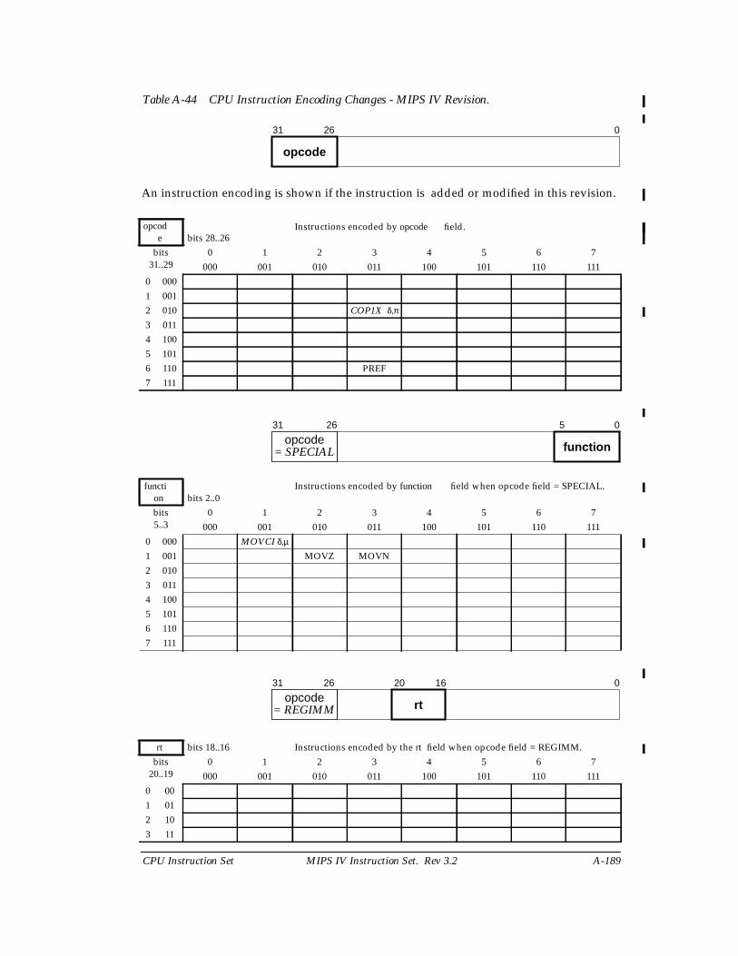
CPU Instruction Set MIPS IV Instruction Set. Rev 3.2 A-189
Table A-44 CPU Instruction Encoding Changes - MIPS IV Revision.
An instruction encoding is shown if the instruction is added or modified in this revision.
opcode bits 28..26
Instructions encoded by opcode field.
bits31..29
0 1 2 3 4 5 6 7000 001 010 011 100 101 110 111
0 0001 0012 010 COP1X δ,π
3 0114 1005 1016 110 PREF7 111
function bits 2..0
Instructions encoded by function field when opcode field = SPECIAL.
bits5..3
0 1 2 3 4 5 6 7000 001 010 011 100 101 110 111
0 000 MOVCI δ,µ
1 001 MOVZ MOVN2 0103 0114 1005 1016 1107 111
rt bits 18..16 Instructions encoded by the rt field when opcode field = REGIMM.bits
20..190 1 2 3 4 5 6 7
000 001 010 011 100 101 110 1110 001 012 103 11
31 26
opcode
0
31 26
opcodefunction
5 0
= SPECIAL
31 26 20 16 0
opcodert= REGIMM
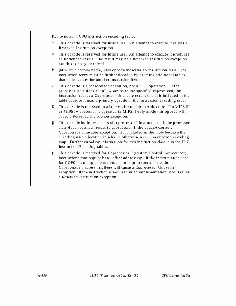
A-190 MIPS IV Instruction Set. Rev 3.2 CPU Instruction Set
Key to notes in CPU instruction encoding tables:
* This opcode is reserved for future use. An attempt to execute it causes aReserved Instruction exception.
= This opcode is reserved for future use. An attempt to execute it producesan undefined result. The result may be a Reserved Instruction exceptionbut this is not guaranteed.
δ (also italic opcode name) This opcode indicates an instruction class. Theinstruction word must be further decoded by examing additional tablesthat show values for another instruction field.
π This opcode is a coprocessor operation, not a CPU operation. If theprocessor state does not allow access to the specified coprocessor, theinstruction causes a Coprocessor Unusable exception. It is included in thetable because it uses a primary opcode in the instruction encoding map.
κ This opcode is removed in a later revision of the architecture. If a MIPS IIIor MIPS IV processor is operated in MIPS II-only mode this opcode willcause a Reserved Instruction exception.
µ This opcode indicates a class of coprocessor 1 instructions. If the processorstate does not allow access to coprocessor 1, the opcode causes aCoprocessor Unusable exception. It is included in the table because theencoding uses a location in what is otherwise a CPU instruction encodingmap. Further encoding information for this instruction class is in the FPUInstruction Encoding tables.
ρ This opcode is reserved for Coprocessor 0 (System Control Coprocessor)instructions that require base+offset addressing. If the instruction is usedfor COP0 in an implementation, an attempt to execute it withoutCoprocessor 0 access privilege will cause a Coprocessor Unusableexception. If the instruction is not used in an implementation, it will causea Reserved Instruction exception.
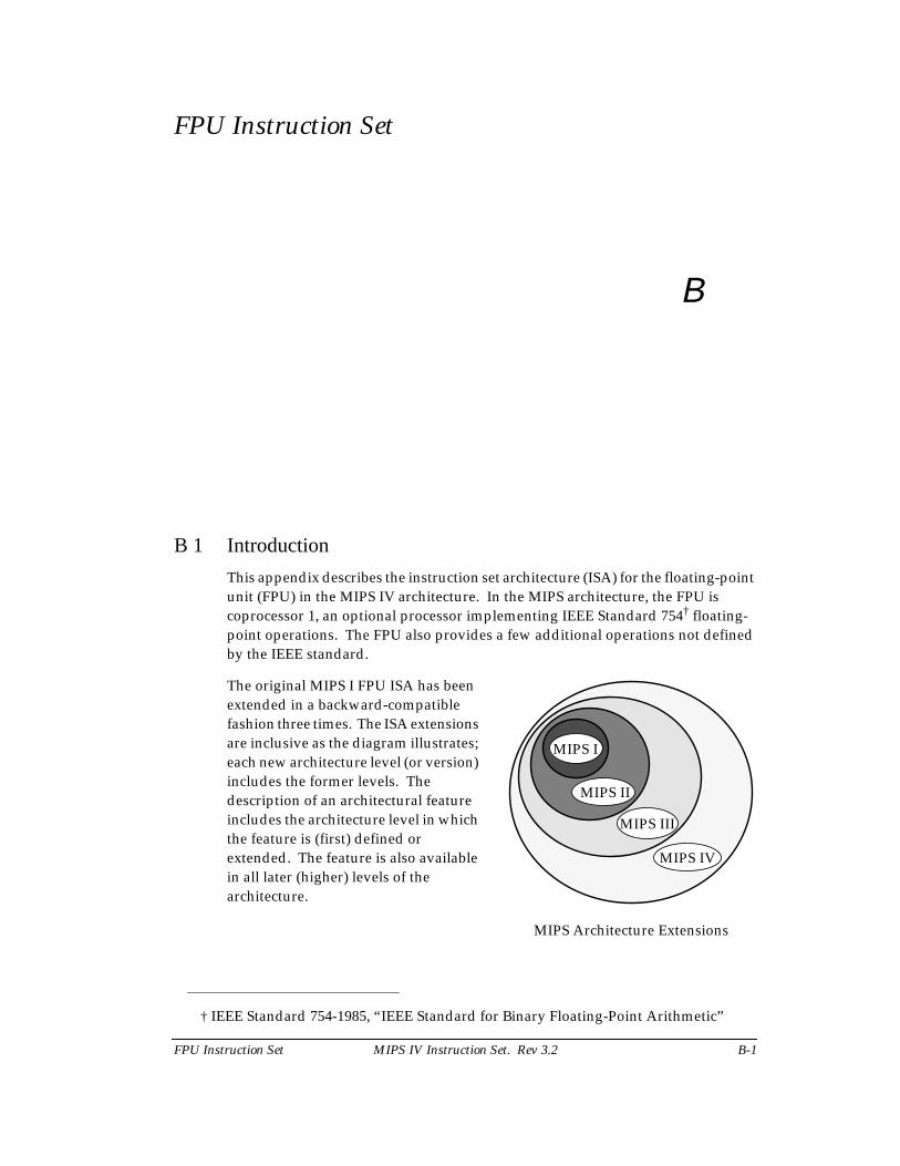
FPU Instruction Set MIPS IV Instruction Set. Rev 3.2 B-1
FPU Instruction Set
B
B 1 Introduction
This appendix describes the instruction set architecture (ISA) for the floating-pointunit (FPU) in the MIPS IV architecture. In the MIPS architecture, the FPU iscoprocessor 1, an optional processor implementing IEEE Standard 754† floating-point operations. The FPU also provides a few additional operations not definedby the IEEE standard.
† IEEE Standard 754-1985, “IEEE Standard for Binary Floating-Point Arithmetic”
MIPS I
MIPS II
MIPS III
MIPS IV
The original MIPS I FPU ISA has beenextended in a backward-compatiblefashion three times. The ISA extensionsare inclusive as the diagram illustrates;each new architecture level (or version)includes the former levels. Thedescription of an architectural featureincludes the architecture level in whichthe feature is (first) defined orextended. The feature is also availablein all later (higher) levels of thearchitecture.
MIPS Architecture Extensions
B-2 MIPS IV Instruction Set. Rev 3.2 FPU Instruction Set
In addition to an ISA, the architecture definition includes processing resources,such as the coprocessor general register set. The 32-bit registers in MIPS I werechanged to 64-bit registers in MIPS III in a way that is not backwards compatible.For changes such as this, processors implementing higher levels of the architecturehave a way to provide the processing resource model for earlier levels. For theFPU there is a mode to select the 32-bit or 64-bit register model. The practical resultis that a processor implementing MIPS IV is also able to run MIPS I, MIPS II, orMIPS III binary programs without change.
If coprocessor 1 is not enabled, an attempt to execute a floating-point instructionwill cause a Coprocessor Unusable exception. Enabling coprocessor 1 is aprivileged operation provided by the System Control Coprocessor. Every systemenvironment will either enable the FPU automatically or provide a means for anapplication to request that it be enabled.
Before the instruction set is described, there is an overview of the FPU data types,registers, and computational model. The FPU instruction set is summarized byfunctional group then each operation is described separately in alphabetical order.The description concludes with the FPU instruction formats and opcode encodingtables. See the CPU instruction set section titled “Description of an Instruction” fora description of the organization of the individual instruction descriptions and thenotation used in them.
The architecture of the floating-point coprocessor consists of:
• Data types
• Operations
• A computational model
• Processing resources (registers)
• An instruction set
The IEEE standard defines the floating-point number data types, the basicarithmetic, comparison, and conversion operations, and a computational model.
The IEEE standard defines neither specific processing resources nor an instructionset. The MIPS architecture defines fixed-point (integer) data types, FPU registersets, control and exception mechanisms, and an instruction set. The architectureinclude non-IEEE FPU control operations, and arithmetic operations (multiply-add, reciprocal, and reciprocal square root) that may not supply results that matchthe IEEE precision rules.
B 2 FPU Data Types
The FPU provides both floating-point and fixed-point data types. The single anddouble precision floating-point data types are those specified by the IEEEstandard. The fixed-point types are the signed integers provided by the CPUarchitecture
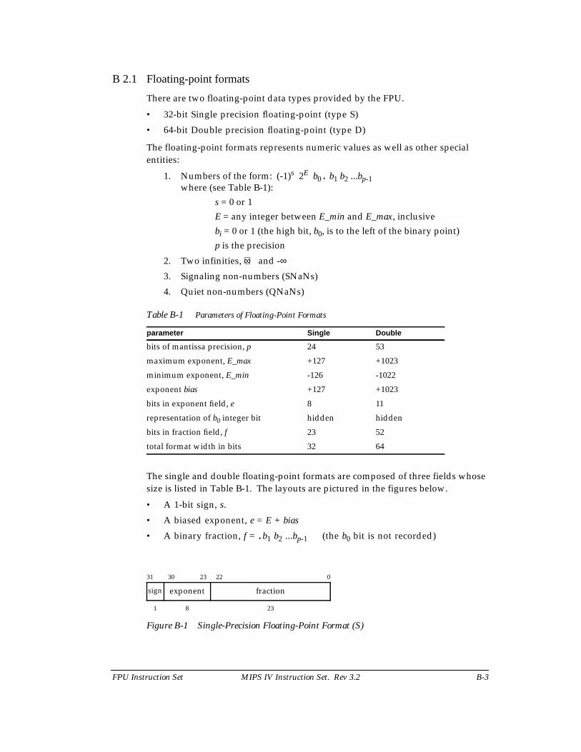
FPU Instruction Set MIPS IV Instruction Set. Rev 3.2 B-3
B 2.1 Floating-point formats
There are two floating-point data types provided by the FPU.
• 32-bit Single precision floating-point (type S)
• 64-bit Double precision floating-point (type D)
The floating-point formats represents numeric values as well as other specialentities:
1. Numbers of the form: (-1)s 2E b0 . b1 b2 ...bp-1where (see Table B-1):
s = 0 or 1
E = any integer between E_min and E_max, inclusive
bi = 0 or 1 (the high bit, b0, is to the left of the binary point)
p is the precision
2. Two infinities, +∞ and -∞3. Signaling non-numbers (SNaNs)
4. Quiet non-numbers (QNaNs)
Table B-1 Parameters of Floating-Point Formats
The single and double floating-point formats are composed of three fields whosesize is listed in Table B-1. The layouts are pictured in the figures below.
• A 1-bit sign, s.
• A biased exponent, e = E + bias
• A binary fraction, f = .b1 b2 ...bp-1 (the b0 bit is not recorded)
Figure B-1 Single-Precision Floating-Point Format (S)
parameter Single Double
bits of mantissa precision, p 24 53
maximum exponent, E_max +127 +1023
minimum exponent, E_min -126 -1022
exponent bias +127 +1023
bits in exponent field, e 8 11
representation of b0 integer bit hidden hidden
bits in fraction field, f 23 52
total format width in bits 32 64
31 30 23 22 0
sign exponent fraction
1 8 23
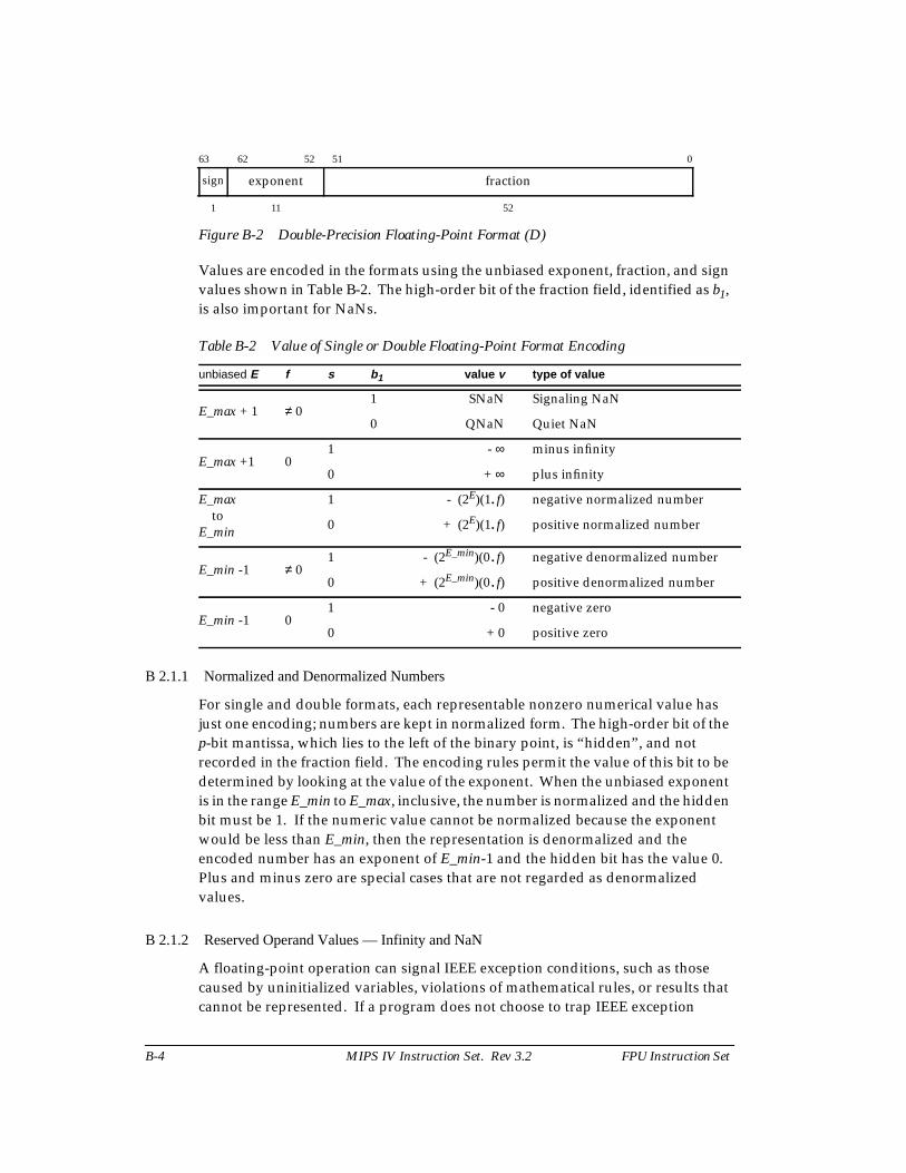
B-4 MIPS IV Instruction Set. Rev 3.2 FPU Instruction Set
Figure B-2 Double-Precision Floating-Point Format (D)
Values are encoded in the formats using the unbiased exponent, fraction, and signvalues shown in Table B-2. The high-order bit of the fraction field, identified as b1,is also important for NaNs.
Table B-2 Value of Single or Double Floating-Point Format Encoding
B 2.1.1 Normalized and Denormalized Numbers
For single and double formats, each representable nonzero numerical value hasjust one encoding; numbers are kept in normalized form. The high-order bit of thep-bit mantissa, which lies to the left of the binary point, is “hidden”, and notrecorded in the fraction field. The encoding rules permit the value of this bit to bedetermined by looking at the value of the exponent. When the unbiased exponentis in the range E_min to E_max, inclusive, the number is normalized and the hiddenbit must be 1. If the numeric value cannot be normalized because the exponentwould be less than E_min, then the representation is denormalized and theencoded number has an exponent of E_min-1 and the hidden bit has the value 0.Plus and minus zero are special cases that are not regarded as denormalizedvalues.
B 2.1.2 Reserved Operand Values — Infinity and NaN
A floating-point operation can signal IEEE exception conditions, such as thosecaused by uninitialized variables, violations of mathematical rules, or results thatcannot be represented. If a program does not choose to trap IEEE exception
63 62 52 51 0
sign exponent fraction
1 11 52
unbiased E f s b 1 value v type of value
E_max + 1 ≠ 01 SNaN Signaling NaN
0 QNaN Quiet NaN
E_max +1 01 - ∞ minus infinity
0 + ∞ plus infinity
E_max toE_min
1 - (2E)(1.f) negative normalized number
0 + (2E)(1.f) positive normalized number
E_min -1 ≠ 01 - (2E_min)(0.f) negative denormalized number
0 + (2E_min)(0.f) positive denormalized number
E_min -1 01 - 0 negative zero
0 + 0 positive zero
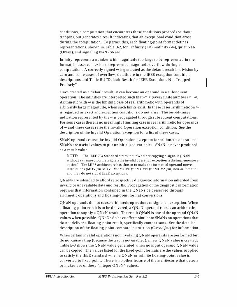
FPU Instruction Set MIPS IV Instruction Set. Rev 3.2 B-5
conditions, a computation that encounters these conditions proceeds withouttrapping but generates a result indicating that an exceptional condition aroseduring the computation. To permit this, each floating-point format definesrepresentations, shown in Table B-2, for +infinity (+∞), -infinity (-∞), quiet NaN(QNan), and signaling NaN (SNaN).
Infinity represents a number with magnitude too large to be represented in theformat; in essence it exists to represent a magnitude overflow during acomputation. A correctly signed ∞ is generated as the default result in division byzero and some cases of overflow; details are in the IEEE exception conditiondescriptions and Table B-4 "Default Result for IEEE Exceptions Not TrappedPrecisely".
Once created as a default result, ∞ can become an operand in a subsequentoperation. The infinities are interpreted such that -∞ < (every finite number) < +∞.Arithmetic with ∞ is the limiting case of real arithmetic with operands ofarbitrarily large magnitude, when such limits exist. In these cases, arithmetic on ∞is regarded as exact and exception conditions do not arise. The out-of-rangeindication represented by the ∞ is propagated through subsequent computations.For some cases there is no meaningful limiting case in real arithmetic for operandsof ∞ and these cases raise the Invalid Operation exception condition. See thedescription of the Invalid Operation exception for a list of these cases.
SNaN operands cause the Invalid Operation exception for arithmetic operations.SNaNs are useful values to put uninitialized variables. SNaN is never producedas a result value.
NOTE: The IEEE 754 Standard states that “Whether copying a signaling NaNwithout a change of format signals the invalid operation exception is the implementor’soption”. The MIPS architecture has chosen to make the formatted operand moveinstructions (MOV.fmt MOVT.fmt MOVF.fmt MOVN.fmt MOVZ.fmt) non-arithmeticand they do not signal IEEE exceptions.
QNaNs are intended to afford retrospective diagnostic information inherited frominvalid or unavailable data and results. Propagation of the diagnostic informationrequires that information contained in the QNaNs be preserved througharithmetic operations and floating-point format conversions.
QNaN operands do not cause arithmetic operations to signal an exception. Whena floating-point result is to be delivered, a QNaN operand causes an arithmeticoperation to supply a QNaN result. The result QNaN is one of the operand QNaNvalues when possible. QNaNs do have effects similar to SNaNs on operations thatdo not deliver a floating-point result, specifically comparisons. See the detaileddescription of the floating-point compare instruction (C.cond.fmt) for information.
When certain invalid operations not involving QNaN operands are performed butdo not cause a trap (because the trap is not enabled), a new QNaN value is created.Table B-3 shows the QNaN value generated when no input operand QNaN valuecan be copied. The values listed for the fixed-point formats are the values suppliedto satisfy the IEEE standard when a QNaN or infinite floating-point value isconverted to fixed point. There is no other feature of the architecture that detectsor makes use of these “integer QNaN” values.
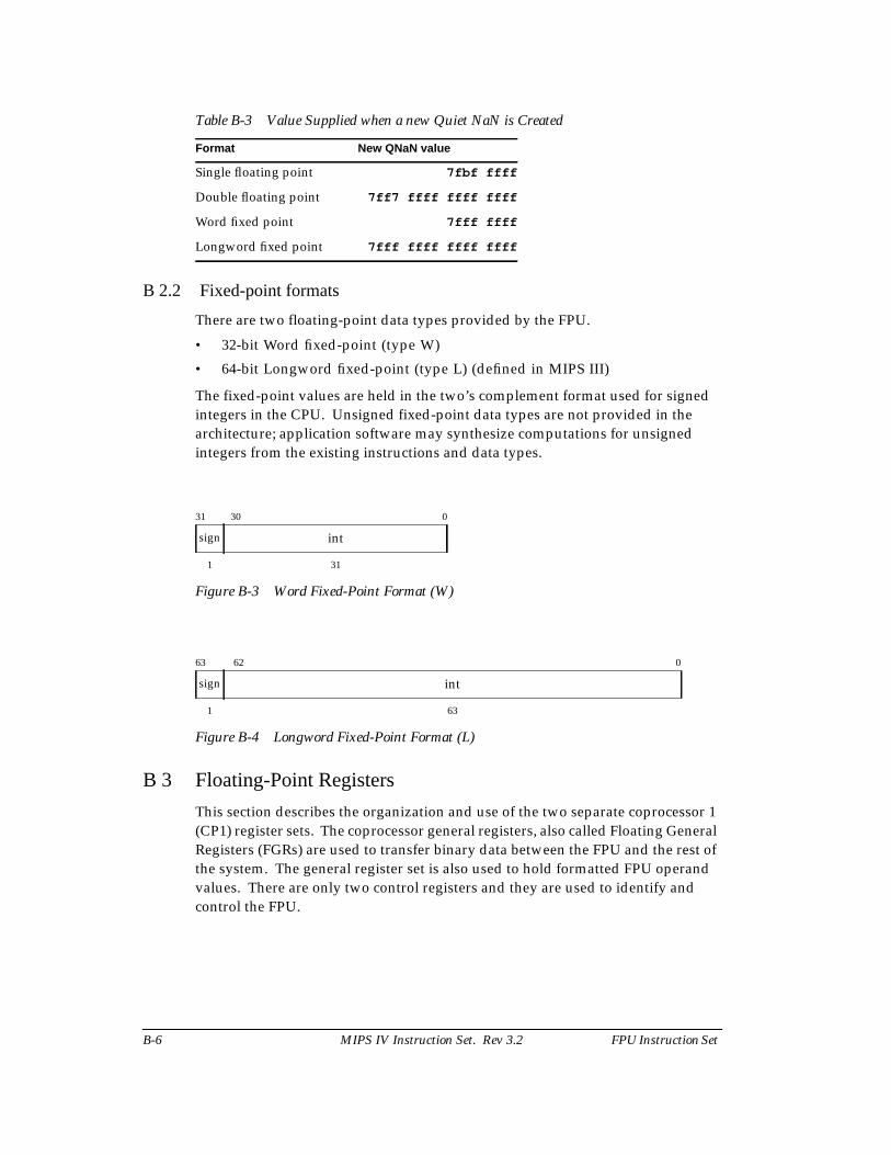
B-6 MIPS IV Instruction Set. Rev 3.2 FPU Instruction Set
Table B-3 Value Supplied when a new Quiet NaN is Created
B 2.2 Fixed-point formats
There are two floating-point data types provided by the FPU.
• 32-bit Word fixed-point (type W)
• 64-bit Longword fixed-point (type L) (defined in MIPS III)
The fixed-point values are held in the two’s complement format used for signedintegers in the CPU. Unsigned fixed-point data types are not provided in thearchitecture; application software may synthesize computations for unsignedintegers from the existing instructions and data types.
Figure B-3 Word Fixed-Point Format (W)
Figure B-4 Longword Fixed-Point Format (L)
B 3 Floating-Point Registers
This section describes the organization and use of the two separate coprocessor 1(CP1) register sets. The coprocessor general registers, also called Floating GeneralRegisters (FGRs) are used to transfer binary data between the FPU and the rest ofthe system. The general register set is also used to hold formatted FPU operandvalues. There are only two control registers and they are used to identify andcontrol the FPU.
Format New QNaN value
Single floating point 7fbf ffff
Double floating point 7ff7 ffff ffff ffff
Word fixed point 7fff ffff
Longword fixed point 7fff ffff ffff ffff
31 30 0
sign int
1 31
63 62 0
sign int
1 63
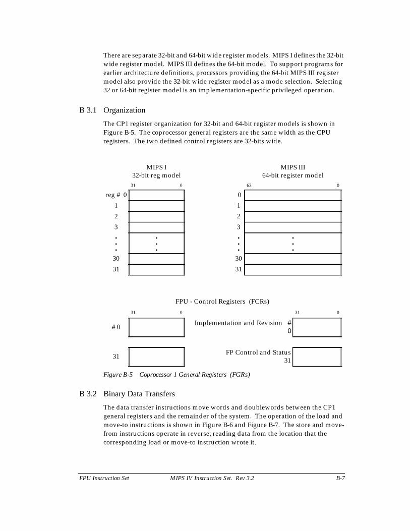
FPU Instruction Set MIPS IV Instruction Set. Rev 3.2 B-7
There are separate 32-bit and 64-bit wide register models. MIPS I defines the 32-bitwide register model. MIPS III defines the 64-bit model. To support programs forearlier architecture definitions, processors providing the 64-bit MIPS III registermodel also provide the 32-bit wide register model as a mode selection. Selecting32 or 64-bit register model is an implementation-specific privileged operation.
B 3.1 Organization
The CP1 register organization for 32-bit and 64-bit register models is shown inFigure B-5. The coprocessor general registers are the same width as the CPUregisters. The two defined control registers are 32-bits wide.
Figure B-5 Coprocessor 1 General Registers (FGRs)
B 3.2 Binary Data Transfers
The data transfer instructions move words and doublewords between the CP1general registers and the remainder of the system. The operation of the load andmove-to instructions is shown in Figure B-6 and Figure B-7. The store and move-from instructions operate in reverse, reading data from the location that thecorresponding load or move-to instruction wrote it.
MIPS I32-bit reg model
MIPS III64-bit register model
31 0 63 0
reg # 0 0
1 1
2 2
3 3...
......
...30 30
31 31
FPU - Control Registers (FCRs)
31 0 31 0
# 0 Implementation and Revision #0
31 FP Control and Status31
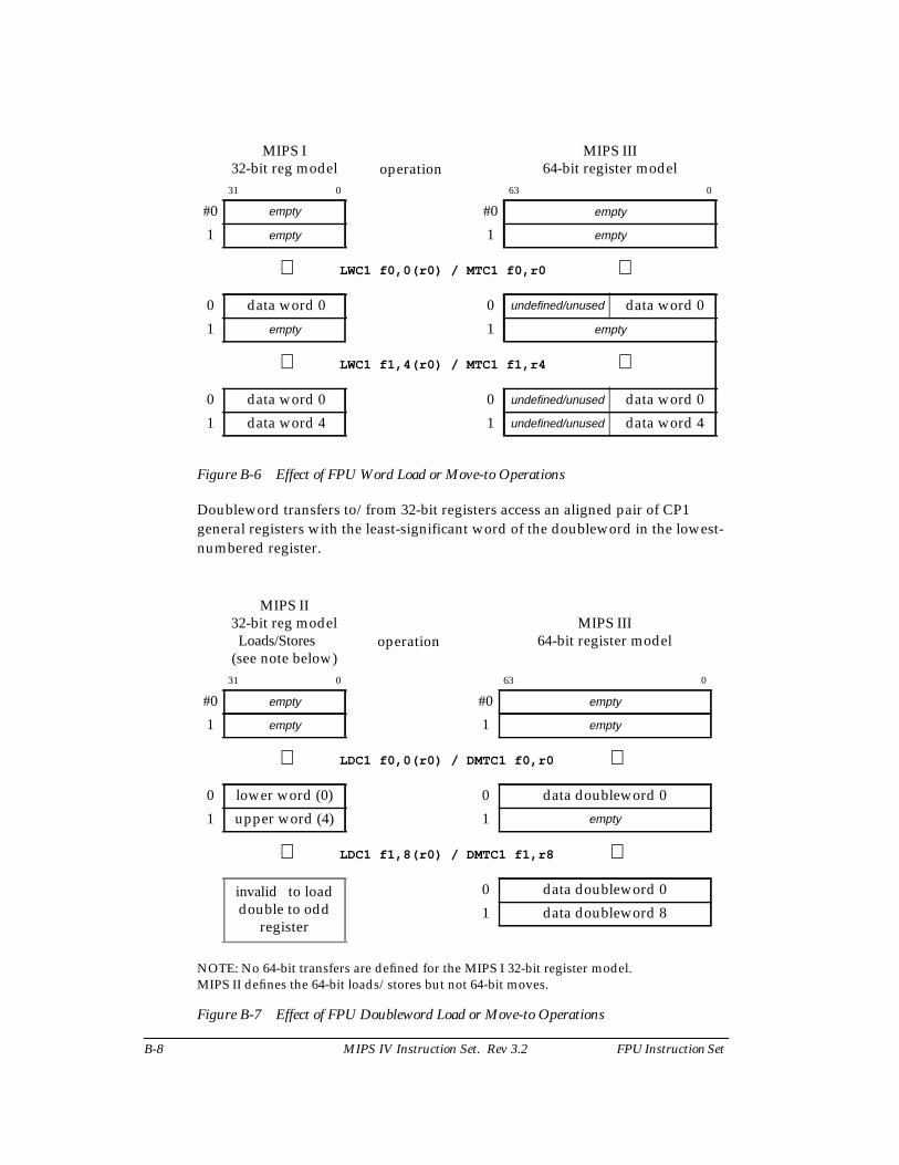
B-8 MIPS IV Instruction Set. Rev 3.2 FPU Instruction Set
Figure B-6 Effect of FPU Word Load or Move-to Operations
Doubleword transfers to/from 32-bit registers access an aligned pair of CP1general registers with the least-significant word of the doubleword in the lowest-numbered register.
Figure B-7 Effect of FPU Doubleword Load or Move-to Operations
MIPS I32-bit reg model operation
MIPS III64-bit register model
31 0 63 0
#0 empty #0 empty
1 empty 1 empty
⇓ LWC1 f0,0(r0) / MTC1 f0,r0 ⇓
0 data word 0 0 undefined/unused data word 0
1 empty 1 empty
⇓ LWC1 f1,4(r0) / MTC1 f1,r4 ⇓
0 data word 0 0 undefined/unused data word 0
1 data word 4 1 undefined/unused data word 4
MIPS II32-bit reg modelLoads/Stores
(see note below)operation
MIPS III64-bit register model
31 0 63 0
#0 empty #0 empty
1 empty 1 empty
⇓ LDC1 f0,0(r0) / DMTC1 f0,r0 ⇓
0 lower word (0) 0 data doubleword 0
1 upper word (4) 1 empty
⇓ LDC1 f1,8(r0) / DMTC1 f1,r8 ⇓
invalid to loaddouble to odd
register
0 data doubleword 0
1 data doubleword 8
NOTE: No 64-bit transfers are defined for the MIPS I 32-bit register model.MIPS II defines the 64-bit loads/stores but not 64-bit moves.
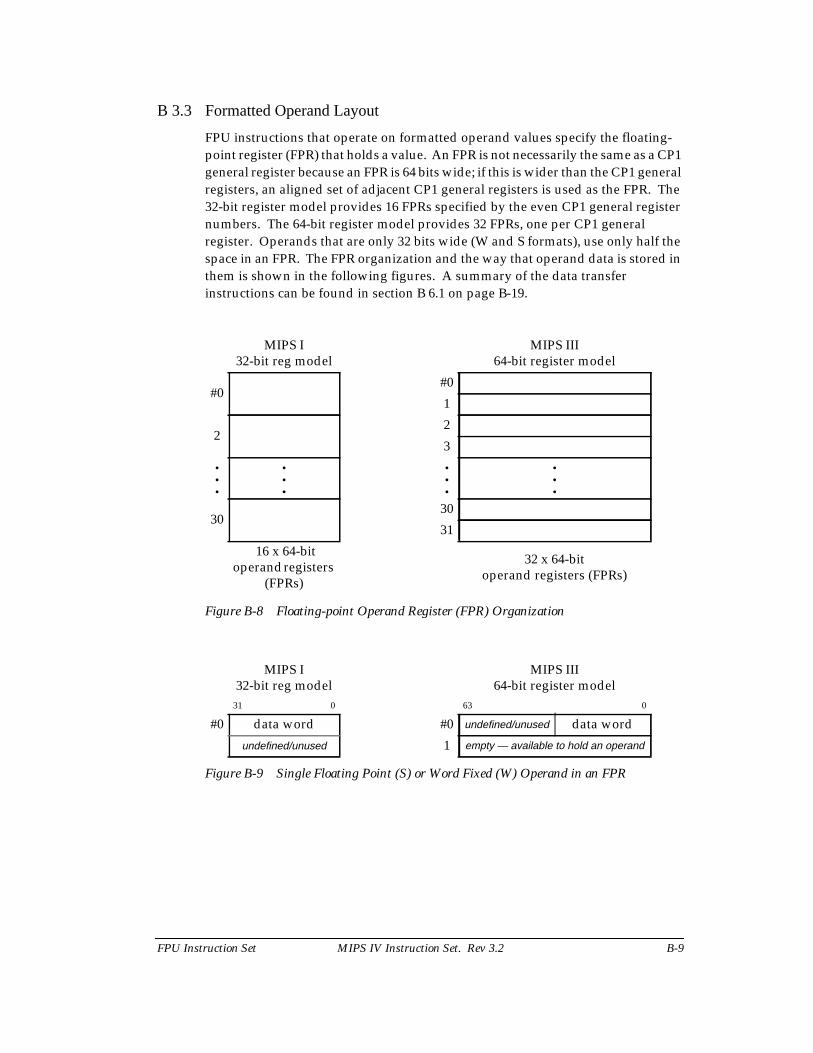
FPU Instruction Set MIPS IV Instruction Set. Rev 3.2 B-9
B 3.3 Formatted Operand Layout
FPU instructions that operate on formatted operand values specify the floating-point register (FPR) that holds a value. An FPR is not necessarily the same as a CP1general register because an FPR is 64 bits wide; if this is wider than the CP1 generalregisters, an aligned set of adjacent CP1 general registers is used as the FPR. The32-bit register model provides 16 FPRs specified by the even CP1 general registernumbers. The 64-bit register model provides 32 FPRs, one per CP1 generalregister. Operands that are only 32 bits wide (W and S formats), use only half thespace in an FPR. The FPR organization and the way that operand data is stored inthem is shown in the following figures. A summary of the data transferinstructions can be found in section B 6.1 on page B-19.
Figure B-8 Floating-point Operand Register (FPR) Organization
Figure B-9 Single Floating Point (S) or Word Fixed (W) Operand in an FPR
MIPS I32-bit reg model
MIPS III64-bit register model
#0#0
1
22
3...
......
...30
30
31
16 x 64-bitoperand registers
(FPRs)
32 x 64-bitoperand registers (FPRs)
MIPS I32-bit reg model
MIPS III64-bit register model
31 0 63 0
#0 data word #0 undefined/unused data word
undefined/unused 1 empty — available to hold an operand
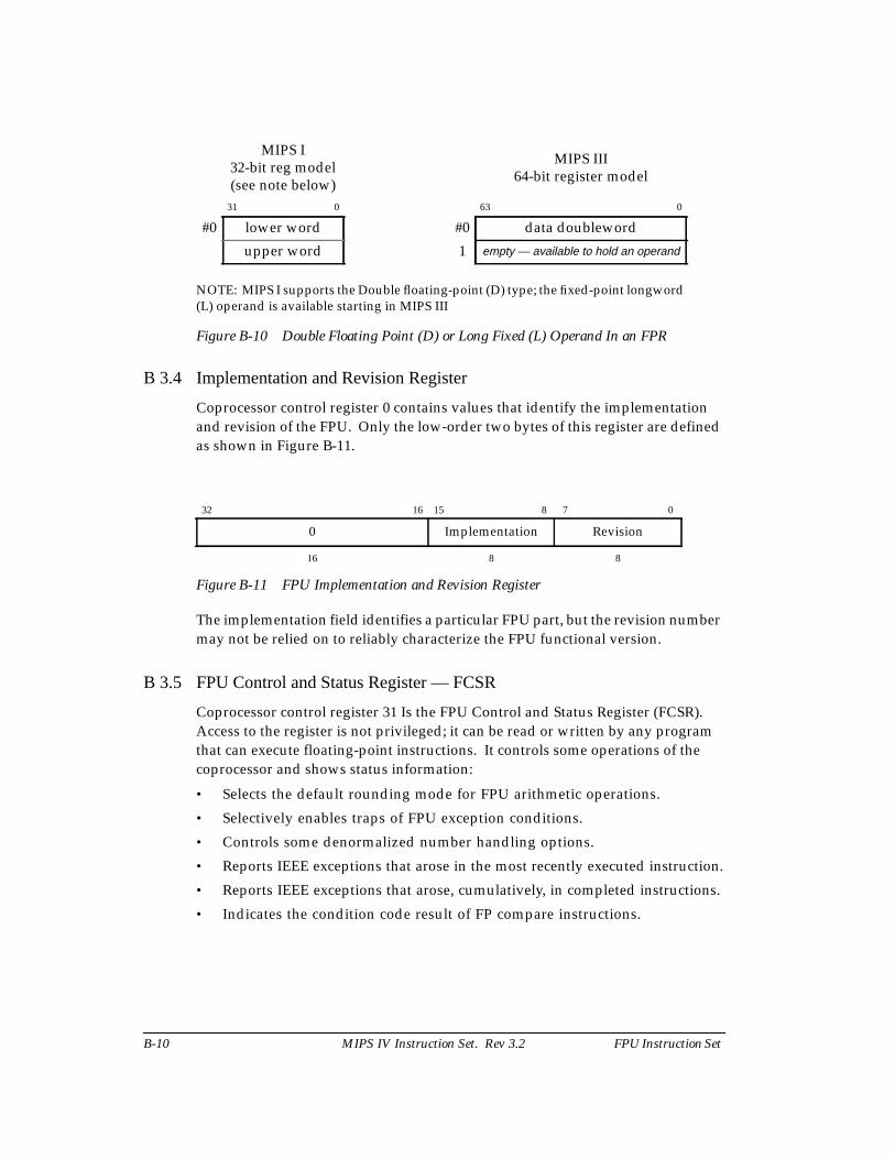
B-10 MIPS IV Instruction Set. Rev 3.2 FPU Instruction Set
Figure B-10 Double Floating Point (D) or Long Fixed (L) Operand In an FPR
B 3.4 Implementation and Revision Register
Coprocessor control register 0 contains values that identify the implementationand revision of the FPU. Only the low-order two bytes of this register are definedas shown in Figure B-11.
Figure B-11 FPU Implementation and Revision Register
The implementation field identifies a particular FPU part, but the revision numbermay not be relied on to reliably characterize the FPU functional version.
B 3.5 FPU Control and Status Register — FCSR
Coprocessor control register 31 Is the FPU Control and Status Register (FCSR).Access to the register is not privileged; it can be read or written by any programthat can execute floating-point instructions. It controls some operations of thecoprocessor and shows status information:
• Selects the default rounding mode for FPU arithmetic operations.
• Selectively enables traps of FPU exception conditions.
• Controls some denormalized number handling options.
• Reports IEEE exceptions that arose in the most recently executed instruction.
• Reports IEEE exceptions that arose, cumulatively, in completed instructions.
• Indicates the condition code result of FP compare instructions.
MIPS I32-bit reg model(see note below)
MIPS III64-bit register model
31 0 63 0
#0 lower word #0 data doubleword
upper word 1 empty — available to hold an operand
NOTE: MIPS I supports the Double floating-point (D) type; the fixed-point longword(L) operand is available starting in MIPS III
32 16 15 8 7 0
0 Implementation Revision
16 8 8
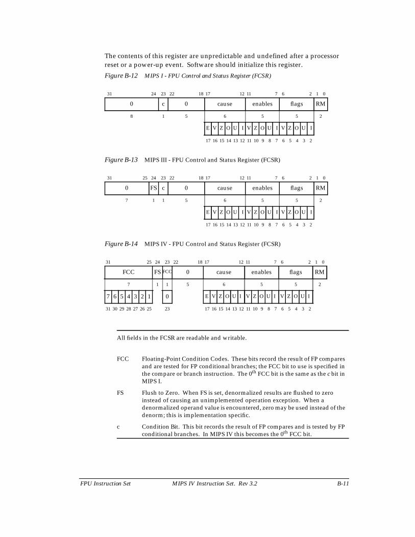
FPU Instruction Set MIPS IV Instruction Set. Rev 3.2 B-11
The contents of this register are unpredictable and undefined after a processorreset or a power-up event. Software should initialize this register.
Figure B-12 MIPS I - FPU Control and Status Register (FCSR)
Figure B-13 MIPS III - FPU Control and Status Register (FCSR)
Figure B-14 MIPS IV - FPU Control and Status Register (FCSR)
31 24 23 22 18 17 12 11 7 6 2 1 0
0 c 0 cause enables flags RM
8 1 5 6 5 5 2
E V Z O U I V Z O U I V Z O U I
17 16 15 14 13 12 11 10 9 8 7 6 5 4 3 2
31 25 24 23 22 18 17 12 11 7 6 2 1 0
0 FS c 0 cause enables flags RM
7 1 1 5 6 5 5 2
E V Z O U I V Z O U I V Z O U I
17 16 15 14 13 12 11 10 9 8 7 6 5 4 3 2
31 25 24 23 22 18 17 12 11 7 6 2 1 0
FCC FS FCC 0 cause enables flags RM
7 1 1 5 6 5 5 2
7 6 5 4 3 2 1 0 E V Z O U I V Z O U I V Z O U I
31 30 29 28 27 26 25 23 17 16 15 14 13 12 11 10 9 8 7 6 5 4 3 2
All fields in the FCSR are readable and writable.
FCC Floating-Point Condition Codes. These bits record the result of FP comparesand are tested for FP conditional branches; the FCC bit to use is specified inthe compare or branch instruction. The 0th FCC bit is the same as the c bit inMIPS I.
FS Flush to Zero. When FS is set, denormalized results are flushed to zeroinstead of causing an unimplemented operation exception. When adenormalized operand value is encountered, zero may be used instead of thedenorm; this is implementation specific.
c Condition Bit. This bit records the result of FP compares and is tested by FPconditional branches. In MIPS IV this becomes the 0th FCC bit.
B-12 MIPS IV Instruction Set. Rev 3.2 FPU Instruction Set
cause Cause bits.These bits indicate the exception conditions that arise during the executionof an FPU arithmetic instruction in precise exception mode. A bit is set to 1if the corresponding exception condition arises during the execution of aninstruction and 0 otherwise. By reading the registers, the exceptionconditions caused by the preceding FPU arithmetic instruction can bedetermined. The meaning of the individual bits is:
E Unimplemented Operation
V Invalid Operation
Z Divide by Zero
O Overflow
U Underflow
I Inexact Result
enables Enable bits (see cause field for bit names).These bits control, for each of the five conditions individually, whether a trapis taken when the IEEE exception condition occurs. The trap occurs whenboth an enable bit and the corresponding cause bit are set during an FPUarithmetic operation or by moving a value to the FCSR. The meaning of theindividual bits is the same as the cause bits. Note that the “E” cause bit hasno corresponding enable bit; the non-IEEE Unimplemented Operationexception defined by MIPS is always enabled.
flags Flag bits. (see cause field for bit names)This field shows the exception conditions that have occurred for completedinstructions since it was last reset. For a completed FPU arithmetic operationthat raises an exception condition the corresponding bits in the flag field areset and the others are unchanged. This field is never reset by hardware andmust be explicitly reset by user software.
RM Rounding Mode. The rounding mode used for most floating-pointoperations (some FP instructions use a specific rounding mode). Therounding modes are:
0 RN -- Round to NearestRound result to the nearest representable value. When tworepresentable values are equally near, round to the value that has aleast significant bit of zero (i.e. is even).
1 RZ -- Round toward ZeroRound result to the value closest to and not greater in magnitudethen the result.
2 RP -- Round toward Plus infinityRound result to the value closest to and not less than the result.
3 RM -- Round toward Minus infinityRound result to the value closest to and not greater than the result.
FPU Instruction Set MIPS IV Instruction Set. Rev 3.2 B-13
B 4 Values in FP Registers
Unlike the CPU, the FPU does not interpret the binary encoding of sourceoperands or produce a binary encoding of results for every operation. The valueheld in a floating-point operand register (FPR) has a format, or type and it mayonly be used by instructions that operate on that format. The format of a value iseither uninterpreted, unknown, or one of the valid numeric formats: single anddouble floating-point and word and long fixed-point. The way that the formattedvalue in an FPR is set and changed is summarized in the state diagram in FigureB-15 and is discussed below.
The value in an FPR is always set when a value is written to the register. When adata transfer instruction writes binary data into an FPR (a load), the FPR gets abinary value that is uninterpreted. A computational or FP register move instructionthat produces a result of type fmt puts a value of type fmt into the result register.
When an FPR with an uninterpreted value is used as a source operand by aninstruction that requires a value of format fmt, the binary contents are interpretedas an encoded value in format fmt and the value in the FPR changes to a value offormat fmt. The binary contents cannot be reinterpreted in a different format.
If an FPR contains a value of format fmt, a computational instruction must not usethe FPR as a source operand of a different format. If this occurs, the value in theregister becomes unknown and the result of the instruction is also a value that isunknown. Using an FPR containing an unknown value as a source operandproduces a result that has an unknown value.
The format of the value in the FPR is unchanged when it is read by a data transferinstruction (a store). A data transfer instruction produces a binary encoding of thevalue contained in the FPR. If the value in the FPR is unknown, the encoded binaryvalue produced by the operation is not defined.
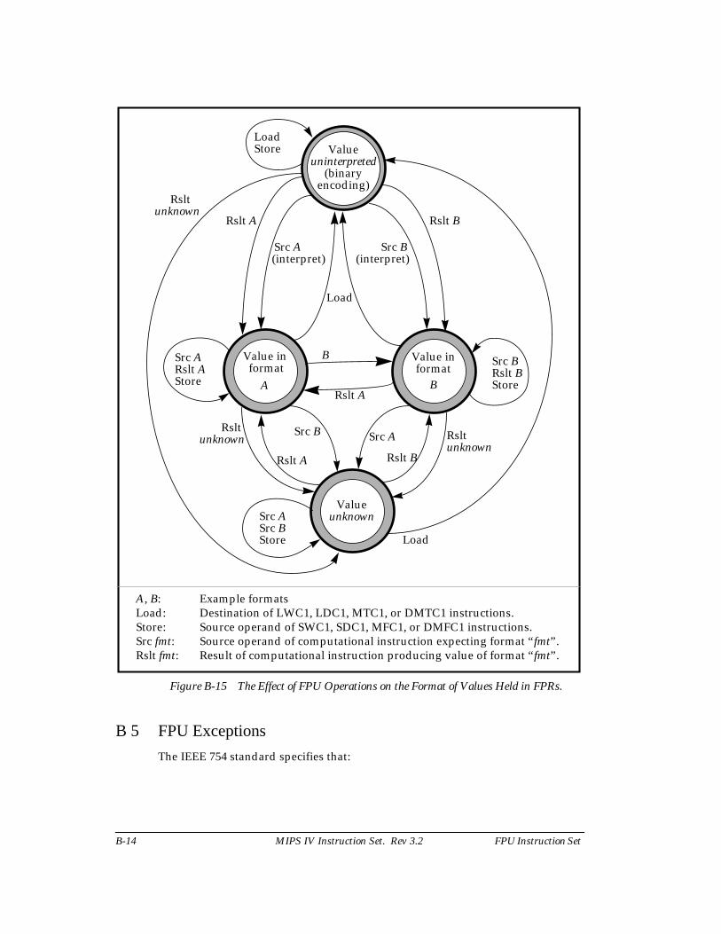
B-14 MIPS IV Instruction Set. Rev 3.2 FPU Instruction Set
B 5 FPU Exceptions
The IEEE 754 standard specifies that:
Value in format
A
Load
Load
Load
Src ASrc BStore
Src ARslt AStore
Store
Rslt B
Src BSrc A
Rslt A
B
Rslt A
Src B Src A
Rslt BRslt A
Src BRslt BStore
A, B: Example formatsLoad: Destination of LWC1, LDC1, MTC1, or DMTC1 instructions.Store: Source operand of SWC1, SDC1, MFC1, or DMFC1 instructions.Src fmt: Source operand of computational instruction expecting format “fmt”.Rslt fmt: Result of computational instruction producing value of format “fmt”.
Figure B-15 The Effect of FPU Operations on the Format of Values Held in FPRs.
(interpret) (interpret)
Rsltunknown Rslt
unknown
Rsltunknown
Valueunknown
Value informat
B
Valueuninterpreted
(binaryencoding)
FPU Instruction Set MIPS IV Instruction Set. Rev 3.2 B-15
There are five types of exceptions that shall be signaled when detected.The signal entails setting a status flag, taking a trap, or possibly doingboth. With each exception should be associated a trap under user control,...
This function is implemented in the MIPS FPU architecture with the cause, enable,and flag fields of the control and status register. The flag bits implement IEEEexception status flags, and the cause and enable bits control exception trapping.Each field has a bit for each of the five IEEE exception conditions and the causefield has an additional exception bit, Unimplemented Operation, used to trap forsoftware emulation assistance.
There may be two exception modes for the FPU, precise and imprecise, and theoperation of the FPU when exception conditions arise depends on the exceptionmode that is currently selected. Every processor is able to operate the FPU in theprecise exception mode. Some processors also have an imprecise exception modein which floating-point performance is greater. Selecting the exception mode,when there is a choice, is a privileged implementation-specific operation.
B 5.1 Precise Exception Mode
In precise exception mode, an exception (trap) caused by a floating-pointoperation is precise. A precise trap occurs before the instruction that causes thetrap, or any following instruction, completes and writes results. If desired, thesoftware trap handler can resume execution of the interrupted instruction streamafter handling the exception.
The cause bit field reports per-instruction exception conditions. The cause bits arewritten during each floating-point arithmetic operation to show the exceptionconditions that arose during the operation. The bits are set to 1 if thecorresponding exception condition arises and 0 otherwise.
A floating-point trap is generated any time both a cause bit and the correspondingenable bit are set. This occurs either during the execution of a floating-pointoperation or by moving a value into the FCSR. There is no enable forUnimplemented Operation; this exception condition always generates a trap.
In a trap handler, the exception conditions that arose during the floating-pointoperation that trapped are reported in the cause field. Before returning from afloating-point interrupt or exception, or setting cause bits with a move to the FCSR,software must first clear the enabled cause bits by a move to the FCSR to preventthe trap from being retaken. User-mode programs can never observe enabledcause bits set. If this information is required in a user-mode handler, then it mustbe passed somewhere other than the status register.
For a floating-point operation that sets only non-enabled cause bits, no trap occursand the default result defined by the IEEE standard is stored (see Table B-4). Whena floating-point operation does not trap, the program can see the exceptionconditions that arose during the operation by reading the cause field.
B-16 MIPS IV Instruction Set. Rev 3.2 FPU Instruction Set
The flag bit field is a cumulative report of IEEE exception conditions that ariseduring instructions that complete; instructions that trap do not update the flag bits.The flag bits are set to 1 if the corresponding IEEE exception is raised andunchanged otherwise. There is no flag bit for the MIPS Uniplemented Operationexception condition. The flag bits are never cleared as a side effect of floating-pointoperations, but may be set or cleared by moving a new value into the FCSR.
B 5.2 Imprecise Exception Mode
In imprecise exception mode, an exception (trap) caused by an IEEE floating-pointoperation is imprecise (Unimplemented Operation exceptions must still besignaled precisely). An imprecise trap occurs at some point after the exceptioncondition arises. In particular, it does not necessarily occur before the instructionthat causes the exception, or following instructions, have completed and writtenresults. The software trap handler can generally neither determine whichinstruction caused the trap nor continue execution of the interrupted instructionstream; it can record the trap that occurred and abort the program.
The meaning of the cause bit field when reading the FCSR is not defined. When acause bit is written in the FCSR by moving data to it, the corresponding flag bit isalso set.
All floating-point operations, whether they cause a trap or not, complete in thesense that they write a result and record exception condition bits in the flag field.When an IEEE exception condition arises during an operation, the default resultdefined by the IEEE standard is stored (see Table B-4).
A floating-point trap is generated when an exception condition arises during afloating-point operation and the corresponding enable bit is set. A trap will alsobe generated when a value with corresponding cause and enable bits set is movedinto the FCSR. There is no enable for Unimplemented Operation; this exceptioncondition always generates a trap.
The flag bit field is a cumulative report of IEEE exception conditions that ariseduring instructions that complete. Because all instructions complete in this mode,unlike precise exception mode, the flag bits include exception conditions thatcause traps. The flag bits are set to 1 if the corresponding IEEE exception is raisedand unchanged otherwise. There is no flag bit for the MIPS UniplementedOperation exception condition. The flag bits are never cleared as a side effect offloating-point operations, but may be set or cleared by moving a new value intothe FCSR.
B 5.3 Exception Condition Definitions
The five exception conditions defined by the IEEE standard are described in thissection. It also describes the MIPS-defined exception condition, UnimplementedOperation, that is used to signal a need for software emulation assistance for aninstruction.
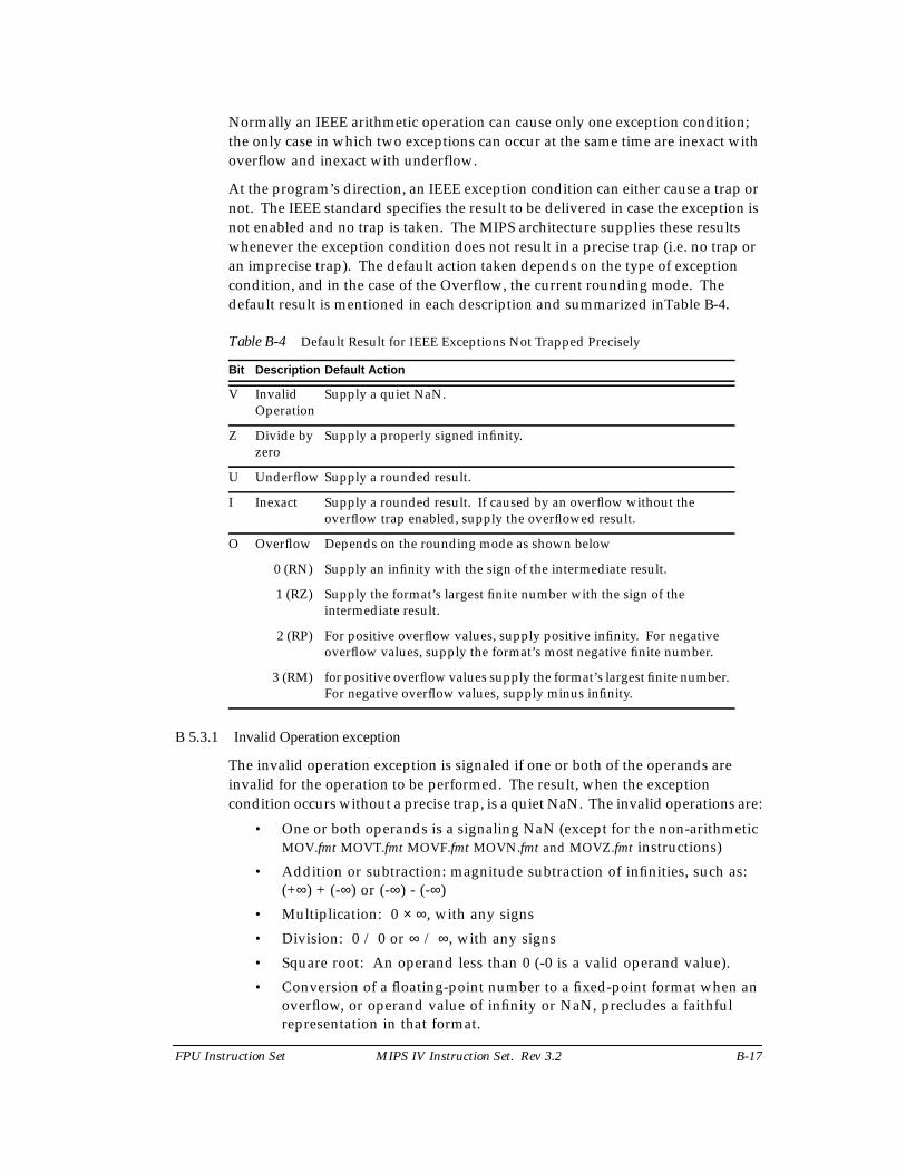
FPU Instruction Set MIPS IV Instruction Set. Rev 3.2 B-17
Normally an IEEE arithmetic operation can cause only one exception condition;the only case in which two exceptions can occur at the same time are inexact withoverflow and inexact with underflow.
At the program’s direction, an IEEE exception condition can either cause a trap ornot. The IEEE standard specifies the result to be delivered in case the exception isnot enabled and no trap is taken. The MIPS architecture supplies these resultswhenever the exception condition does not result in a precise trap (i.e. no trap oran imprecise trap). The default action taken depends on the type of exceptioncondition, and in the case of the Overflow, the current rounding mode. Thedefault result is mentioned in each description and summarized inTable B-4.
Table B-4 Default Result for IEEE Exceptions Not Trapped Precisely
B 5.3.1 Invalid Operation exception
The invalid operation exception is signaled if one or both of the operands areinvalid for the operation to be performed. The result, when the exceptioncondition occurs without a precise trap, is a quiet NaN. The invalid operations are:
• One or both operands is a signaling NaN (except for the non-arithmeticMOV.fmt MOVT.fmt MOVF.fmt MOVN.fmt and MOVZ.fmt instructions)
• Addition or subtraction: magnitude subtraction of infinities, such as:(+∞) + (-∞) or (-∞) - (-∞)
• Multiplication: 0 × ∞, with any signs
• Division: 0 / 0 or ∞ / ∞, with any signs
• Square root: An operand less than 0 (-0 is a valid operand value).
• Conversion of a floating-point number to a fixed-point format when anoverflow, or operand value of infinity or NaN, precludes a faithfulrepresentation in that format.
Bit Description Default Action
V InvalidOperation
Supply a quiet NaN.
Z Divide byzero
Supply a properly signed infinity.
U Underflow Supply a rounded result.
I Inexact Supply a rounded result. If caused by an overflow without theoverflow trap enabled, supply the overflowed result.
O Overflow Depends on the rounding mode as shown below
0 (RN) Supply an infinity with the sign of the intermediate result.
1 (RZ) Supply the format’s largest finite number with the sign of theintermediate result.
2 (RP) For positive overflow values, supply positive infinity. For negativeoverflow values, supply the format’s most negative finite number.
3 (RM) for positive overflow values supply the format’s largest finite number.For negative overflow values, supply minus infinity.
B-18 MIPS IV Instruction Set. Rev 3.2 FPU Instruction Set
• Some comparison operations in which one or both of the operands is aQNaN value. The definition of the compare operation (C.cond.fmt) hastables showing the comparisons that do and do not signal theexception.
B 5.3.2 Division By Zero exception
The division by zero exception is signaled on an implemented divide operation ifthe divisor is zero and the dividend is a finite nonzero number. The result, whenno precise trap occurs, is a correctly signed infinity. The divisions (0/0) and (∞/0)do not cause the division by zero exception. The result of (0/0) is an InvalidOperation exception condition. The result of (∞/0) is a correctly signed infinity.
B 5.3.3 Overflow exception
The overflow exception is signaled when what would have been the magnitude ofthe rounded floating-point result, were the exponent range unbounded, is largerthan the destination format’s largest finite number. The result, when no precisetrap occurs, is determined by the rounding mode and the sign of the intermediateresult as shown in Table B-4.
B 5.3.4 Underflow exception
Two related events contribute to underflow. One is the creation of a tiny non-zeroresult between ±2E_min which, because it is tiny, may cause some other exceptionlater such as overflow on division. The other is extraordinary loss of accuracyduring the approximation of such tiny numbers by denormalized numbers. TheIEEE standard permits a choice in how these events are detected, but requires thatthey must be detected the same way for all operations.
The IEEE standard specifies that “tininess” may be detected either: “afterrounding” (when a nonzero result computed as though the exponent range wereunbounded would lie strictly between ±2E_min), or “before rounding” (when anonzero result computed as though both the exponent range and the precisionwere unbounded would lie strictly between ±2E_min). The MIPS architecturespecifies that tininess is detected after rounding.
The IEEE standard specifies that loss of accuracy may be detected as either“denormalization loss” (when the delivered result differs from what would havebeen computed if the exponent range were unbounded), or “inexact result” (whenthe delivered result differs from what would have been computed if both theexponent range and precision were unbounded). The MIPS architecture specifiesthat loss of accuracy is detected as inexact result.
When an underflow trap is not enabled, underflow is signaled only when bothtininess and loss of accuracy have been detected. The delivered result might bezero, denormalized, or ±2E_min. When an underflow trap is enabled (via the FCSRenable field bit), underflow is signaled when tininess is detected regardless of lossof accuracy.
FPU Instruction Set MIPS IV Instruction Set. Rev 3.2 B-19
B 5.3.5 Inexact exception
If the rounded result of an operation is not exact or if it overflows without anoverflow trap, then the inexact exception is signaled.
B 5.3.6 Unimplemented Operation exception
This MIPS defined (non-IEEE) exception is to provide software emulation support.The architecture is designed to permit a combination of hardware and software tofully implement the architecture. Operations that are not fully supported inhardware cause an Unimplemented Operation exception so that software mayperform the operation. There is no enable bit for this condition; it always causes atrap. After the appropriate emulation or other operation is done in a softwareexception handler, the original instruction stream can be continued.
B 6 Functional Instruction Groups
The FPU instructions are divided into the following functional groups:
• Data Transfer
• Arithmetic
• Conversion
• Formatted Operand Value Move
• Conditional Branch
• Miscellaneous
B 6.1 Data Transfer Instructions
The FPU has two separate register sets: coprocessor general registers andcoprocessor control registers. The FPU has a load/store architecture; allcomputations are done on data held in coprocessor general registers. The controlregisters are used to control FPU operation. Data is transferred between registersand the rest of the system with dedicated load, store, and move instructions. Thetransferred data is treated as unformatted binary data; no format conversions areperformed and, therefore, no IEEE floating-point exceptions can occur.
The supported transfer operations are:
All coprocessor loads and stores operate on naturally-aligned data items. Anattempt to load or store to an address that is not naturally aligned for the data itemwill cause an Address Error exception. Regardless of byte-numbering order
• FPU general reg ↔ memory (word/doubleword load/store)
• FPU general reg ↔ CPU general reg (word/doubleword move)
• FPU control reg ↔ CPU general reg (word move)
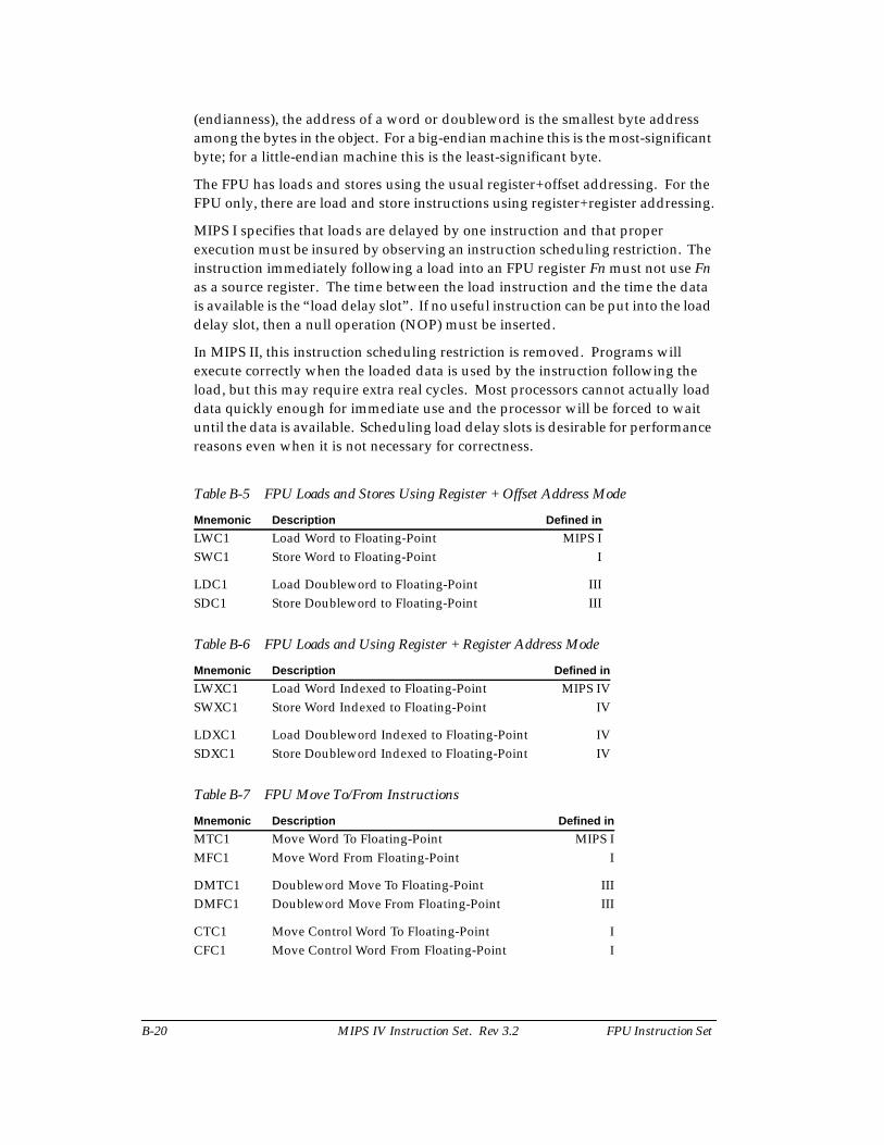
B-20 MIPS IV Instruction Set. Rev 3.2 FPU Instruction Set
(endianness), the address of a word or doubleword is the smallest byte addressamong the bytes in the object. For a big-endian machine this is the most-significantbyte; for a little-endian machine this is the least-significant byte.
The FPU has loads and stores using the usual register+offset addressing. For theFPU only, there are load and store instructions using register+register addressing.
MIPS I specifies that loads are delayed by one instruction and that properexecution must be insured by observing an instruction scheduling restriction. Theinstruction immediately following a load into an FPU register Fn must not use Fnas a source register. The time between the load instruction and the time the datais available is the “load delay slot”. If no useful instruction can be put into the loaddelay slot, then a null operation (NOP) must be inserted.
In MIPS II, this instruction scheduling restriction is removed. Programs willexecute correctly when the loaded data is used by the instruction following theload, but this may require extra real cycles. Most processors cannot actually loaddata quickly enough for immediate use and the processor will be forced to waituntil the data is available. Scheduling load delay slots is desirable for performancereasons even when it is not necessary for correctness.
Table B-5 FPU Loads and Stores Using Register + Offset Address Mode
Table B-6 FPU Loads and Using Register + Register Address Mode
Table B-7 FPU Move To/From Instructions
Mnemonic Description Defined in
LWC1 Load Word to Floating-Point MIPS ISWC1 Store Word to Floating-Point I
LDC1 Load Doubleword to Floating-Point IIISDC1 Store Doubleword to Floating-Point III
Mnemonic Description Defined in
LWXC1 Load Word Indexed to Floating-Point MIPS IVSWXC1 Store Word Indexed to Floating-Point IV
LDXC1 Load Doubleword Indexed to Floating-Point IVSDXC1 Store Doubleword Indexed to Floating-Point IV
Mnemonic Description Defined in
MTC1 Move Word To Floating-Point MIPS IMFC1 Move Word From Floating-Point I
DMTC1 Doubleword Move To Floating-Point IIIDMFC1 Doubleword Move From Floating-Point III
CTC1 Move Control Word To Floating-Point ICFC1 Move Control Word From Floating-Point I
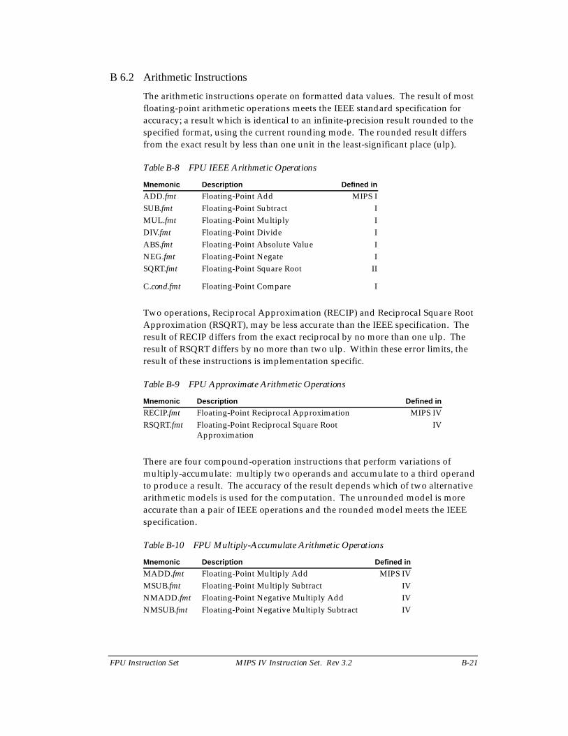
FPU Instruction Set MIPS IV Instruction Set. Rev 3.2 B-21
B 6.2 Arithmetic Instructions
The arithmetic instructions operate on formatted data values. The result of mostfloating-point arithmetic operations meets the IEEE standard specification foraccuracy; a result which is identical to an infinite-precision result rounded to thespecified format, using the current rounding mode. The rounded result differsfrom the exact result by less than one unit in the least-significant place (ulp).
Table B-8 FPU IEEE Arithmetic Operations
Two operations, Reciprocal Approximation (RECIP) and Reciprocal Square RootApproximation (RSQRT), may be less accurate than the IEEE specification. Theresult of RECIP differs from the exact reciprocal by no more than one ulp. Theresult of RSQRT differs by no more than two ulp. Within these error limits, theresult of these instructions is implementation specific.
Table B-9 FPU Approximate Arithmetic Operations
There are four compound-operation instructions that perform variations ofmultiply-accumulate: multiply two operands and accumulate to a third operandto produce a result. The accuracy of the result depends which of two alternativearithmetic models is used for the computation. The unrounded model is moreaccurate than a pair of IEEE operations and the rounded model meets the IEEEspecification.
Table B-10 FPU Multiply-Accumulate Arithmetic Operations
Mnemonic Description Defined in
ADD.fmt Floating-Point Add MIPS ISUB.fmt Floating-Point Subtract IMUL.fmt Floating-Point Multiply IDIV.fmt Floating-Point Divide IABS.fmt Floating-Point Absolute Value INEG.fmt Floating-Point Negate ISQRT.fmt Floating-Point Square Root II
C.cond.fmt Floating-Point Compare I
Mnemonic Description Defined in
RECIP.fmt Floating-Point Reciprocal Approximation MIPS IVRSQRT.fmt Floating-Point Reciprocal Square Root
ApproximationIV
Mnemonic Description Defined in
MADD.fmt Floating-Point Multiply Add MIPS IVMSUB.fmt Floating-Point Multiply Subtract IVNMADD.fmt Floating-Point Negative Multiply Add IVNMSUB.fmt Floating-Point Negative Multiply Subtract IV
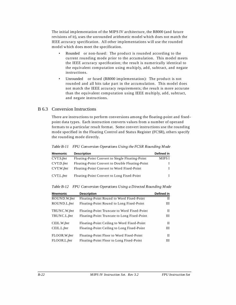
B-22 MIPS IV Instruction Set. Rev 3.2 FPU Instruction Set
The initial implementation of the MIPS IV architecture, the R8000 (and futurerevisions of it), uses the unrounded arithmetic model which does not match theIEEE accuracy specification. All other implementations will use the roundedmodel which does meet the specification.
• Rounded or non-fused: The product is rounded according to thecurrent rounding mode prior to the accumulation. This model meetsthe IEEE accuracy specification; the result is numerically identical tothe equivalent computation using multiply, add, subtract, and negateinstructions.
• Unrounded or fused (R8000 implementation): The product is notrounded and all bits take part in the accumulation. This model doesnot match the IEEE accuracy requirements; the result is more accuratethan the equivalent computation using IEEE multiply, add, subtract,and negate instructions.
B 6.3 Conversion Instructions
There are instructions to perform conversions among the floating-point and fixed-point data types. Each instruction converts values from a number of operandformats to a particular result format. Some convert instructions use the roundingmode specified in the Floating Control and Status Register (FCSR), others specifythe rounding mode directly.
Table B-11 FPU Conversion Operations Using the FCSR Rounding Mode
Table B-12 FPU Conversion Operations Using a Directed Rounding Mode
Mnemonic Description Defined in
CVT.S.fmt Floating-Point Convert to Single Floating-Point MIPS ICVT.D.fmt Floating-Point Convert to Double Floating-Point ICVT.W.fmt Floating-Point Convert to Word Fixed-Point I
CVT.L.fmt Floating-Point Convert to Long Fixed-Point I
Mnemonic Description Defined in
ROUND.W.fmt Floating-Point Round to Word Fixed-Point IIROUND.L.fmt Floating-Point Round to Long Fixed-Point III
TRUNC.W.fmt Floating-Point Truncate to Word Fixed-Point IITRUNC.L.fmt Floating-Point Truncate to Long Fixed-Point III
CEIL.W.fmt Floating-Point Ceiling to Word Fixed-Point IICEIL.L.fmt Floating-Point Ceiling to Long Fixed-Point III
FLOOR.W.fmt Floating-Point Floor to Word Fixed-Point IIFLOOR.L.fmt Floating-Point Floor to Long Fixed-Point III
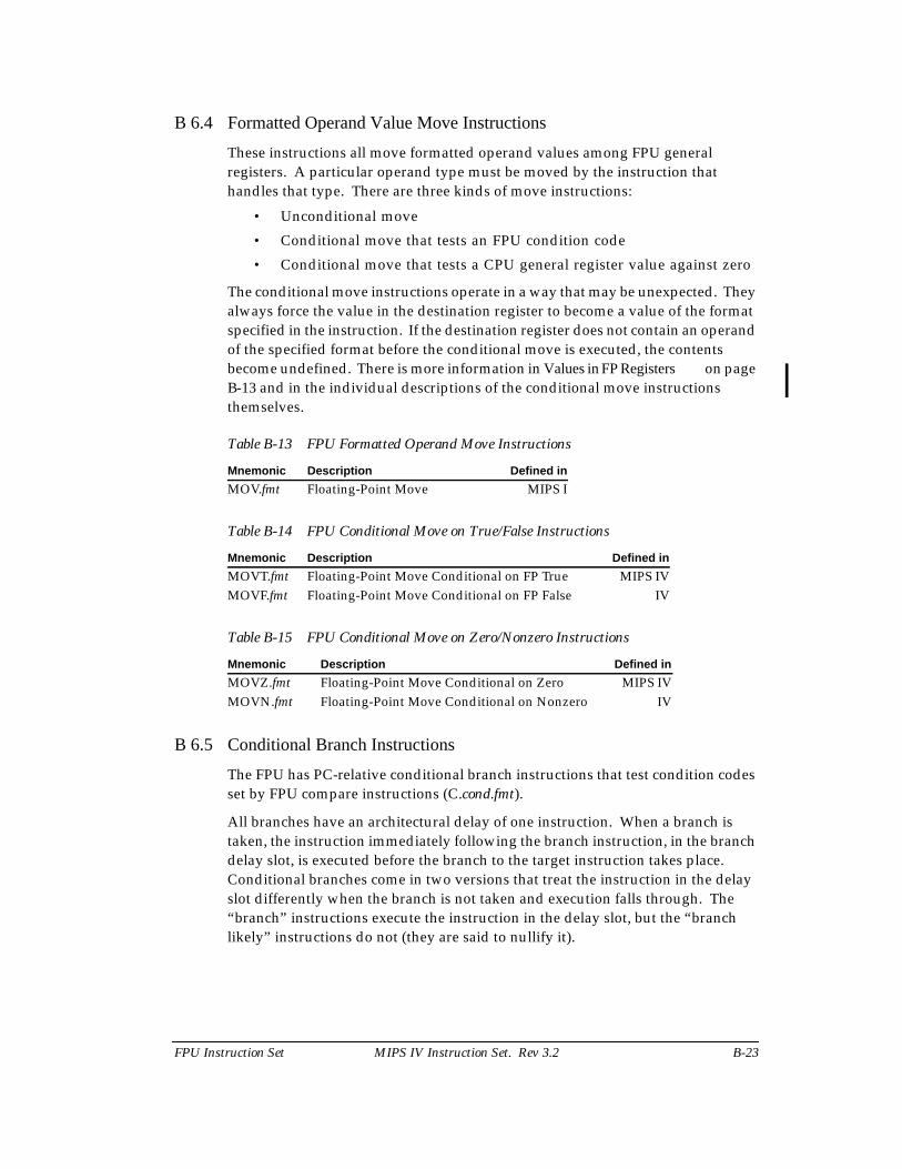
FPU Instruction Set MIPS IV Instruction Set. Rev 3.2 B-23
B 6.4 Formatted Operand Value Move Instructions
These instructions all move formatted operand values among FPU generalregisters. A particular operand type must be moved by the instruction thathandles that type. There are three kinds of move instructions:
• Unconditional move
• Conditional move that tests an FPU condition code
• Conditional move that tests a CPU general register value against zero
The conditional move instructions operate in a way that may be unexpected. Theyalways force the value in the destination register to become a value of the formatspecified in the instruction. If the destination register does not contain an operandof the specified format before the conditional move is executed, the contentsbecome undefined. There is more information in Values in FP Registers on pageB-13 and in the individual descriptions of the conditional move instructionsthemselves.
Table B-13 FPU Formatted Operand Move Instructions
Table B-14 FPU Conditional Move on True/False Instructions
Table B-15 FPU Conditional Move on Zero/Nonzero Instructions
B 6.5 Conditional Branch Instructions
The FPU has PC-relative conditional branch instructions that test condition codesset by FPU compare instructions (C.cond.fmt).
All branches have an architectural delay of one instruction. When a branch istaken, the instruction immediately following the branch instruction, in the branchdelay slot, is executed before the branch to the target instruction takes place.Conditional branches come in two versions that treat the instruction in the delayslot differently when the branch is not taken and execution falls through. The“branch” instructions execute the instruction in the delay slot, but the “branchlikely” instructions do not (they are said to nullify it).
Mnemonic Description Defined in
MOV.fmt Floating-Point Move MIPS I
Mnemonic Description Defined in
MOVT.fmt Floating-Point Move Conditional on FP True MIPS IVMOVF.fmt Floating-Point Move Conditional on FP False IV
Mnemonic Description Defined in
MOVZ.fmt Floating-Point Move Conditional on Zero MIPS IVMOVN.fmt Floating-Point Move Conditional on Nonzero IV
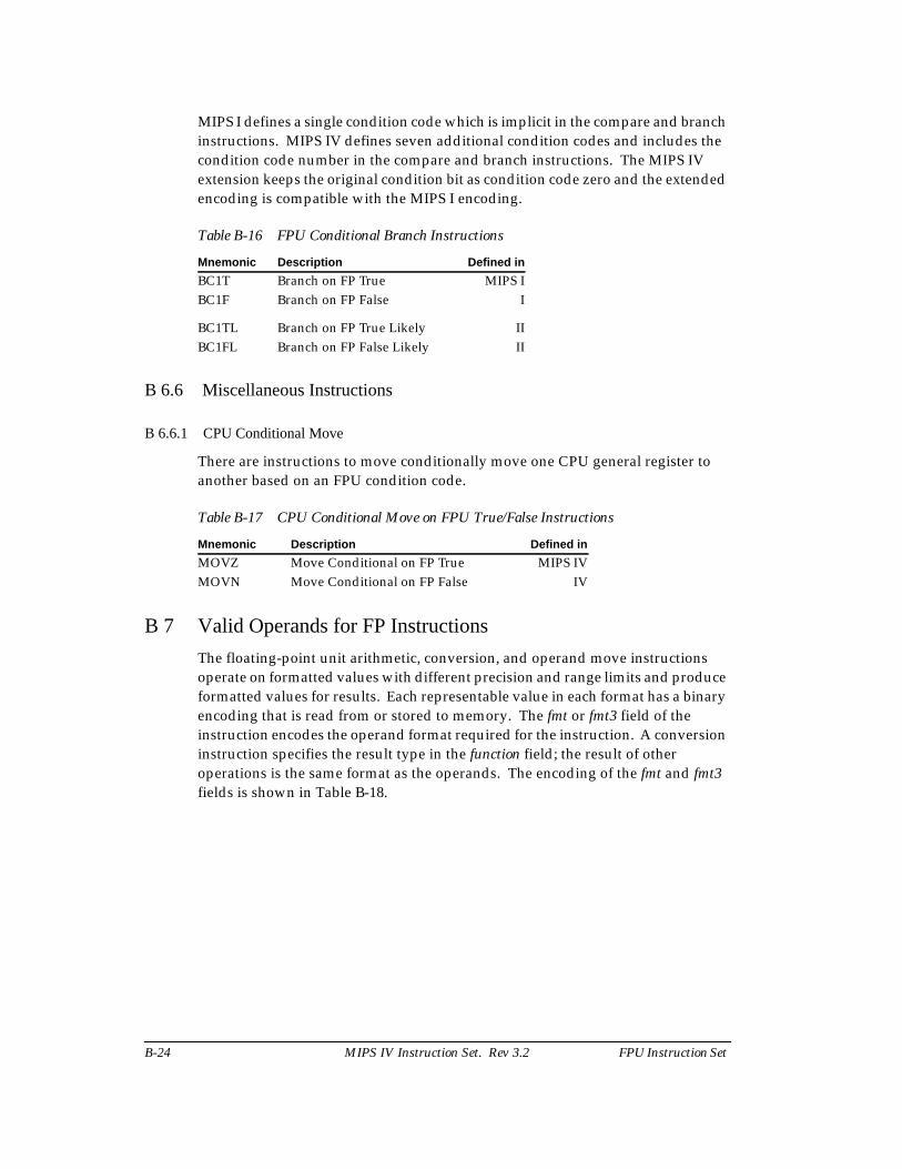
B-24 MIPS IV Instruction Set. Rev 3.2 FPU Instruction Set
MIPS I defines a single condition code which is implicit in the compare and branchinstructions. MIPS IV defines seven additional condition codes and includes thecondition code number in the compare and branch instructions. The MIPS IVextension keeps the original condition bit as condition code zero and the extendedencoding is compatible with the MIPS I encoding.
Table B-16 FPU Conditional Branch Instructions
B 6.6 Miscellaneous Instructions
B 6.6.1 CPU Conditional Move
There are instructions to move conditionally move one CPU general register toanother based on an FPU condition code.
Table B-17 CPU Conditional Move on FPU True/False Instructions
B 7 Valid Operands for FP Instructions
The floating-point unit arithmetic, conversion, and operand move instructionsoperate on formatted values with different precision and range limits and produceformatted values for results. Each representable value in each format has a binaryencoding that is read from or stored to memory. The fmt or fmt3 field of theinstruction encodes the operand format required for the instruction. A conversioninstruction specifies the result type in the function field; the result of otheroperations is the same format as the operands. The encoding of the fmt and fmt3fields is shown in Table B-18.
Mnemonic Description Defined in
BC1T Branch on FP True MIPS IBC1F Branch on FP False I
BC1TL Branch on FP True Likely IIBC1FL Branch on FP False Likely II
Mnemonic Description Defined in
MOVZ Move Conditional on FP True MIPS IVMOVN Move Conditional on FP False IV
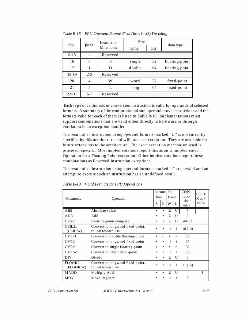
FPU Instruction Set MIPS IV Instruction Set. Rev 3.2 B-25
Table B-18 FPU Operand Format Field (fmt, fmt3) Decoding
Each type of arithmetic or conversion instruction is valid for operands of selectedformats. A summary of the computational and operand move instructions and theformats valid for each of them is listed in Table B-19. Implementations mustsupport combinations that are valid either directly in hardware or throughemulation in an exception handler.
The result of an instruction using operand formats marked “U ” is not currentlyspecified by this architecture and will cause an exception. They are available forfuture extensions to the architecture. The exact exception mechanism used isprocessor specific. Most implementations report this as an UnimplementedOperation for a Floating Point exception. Other implementations report thesecombinations as Reserved Instruction exceptions.
The result of an instruction using operand formats marked “i” are invalid and anattempt to execute such an instruction has an undefined result.
Table B-19 Valid Formats for FPU Operations
fmt fmt3InstructionMnemonic
Sizedata type
name bits
0-15 - Reserved
16 0 S single 32 floating-point
17 1 D double 64 floating-point
18-19 2-3 Reserved
20 4 W word 32 fixed-point
21 5 L long 64 fixed-point
22–31 6-7 Reserved
Mnemonic Operation
operand fmt COP1func-tion
value
COP1X op4value
float fixed
S D W L
ABS Absolute value • • U U 5ADD Add • • U U 0C.cond Floating-point compare • • U U 48–63CEIL.L,(CEIL.W)
Convert to longword fixed-point,round toward +∞ • • i i 10 (14)
CVT.D Convert to double floating-point • i • • 33CVT.L Convert to longword fixed-point • • i i 37CVT.S Convert to single floating-point i • • • 32CVT.W Convert to 32-bit fixed-point • • i i 36DIV Divide • • U U 3FLOOR.L,(FLOOR.W)
Convert to longword fixed-point,round toward -∞ • • i i 11 (15)
MADD Multiply-Add • • U U 4MOV Move Register • • i i 6
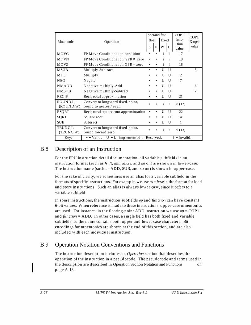
B-26 MIPS IV Instruction Set. Rev 3.2 FPU Instruction Set
B 8 Description of an Instruction
For the FPU instruction detail documentation, all variable subfields in aninstruction format (such as fs, ft, immediate, and so on) are shown in lower-case.The instruction name (such as ADD, SUB, and so on) is shown in upper-case.
For the sake of clarity, we sometimes use an alias for a variable subfield in theformats of specific instructions. For example, we use rs = base in the format for loadand store instructions. Such an alias is always lower case, since it refers to avariable subfield.
In some instructions, the instruction subfields op and function can have constant6-bit values. When reference is made to these instructions, upper-case mnemonicsare used. For instance, in the floating-point ADD instruction we use op = COP1and function = ADD. In other cases, a single field has both fixed and variablesubfields, so the name contains both upper and lower case characters. Bitencodings for mnemonics are shown at the end of this section, and are alsoincluded with each individual instruction.
B 9 Operation Notation Conventions and Functions
The instruction description includes an Operation section that describes theoperation of the instruction in a pseudocode. The pseudocode and terms used inthe description are described in Operation Section Notation and Functions onpage A-18.
MOVC FP Move Conditional on condition • • i i 17MOVN FP Move Conditional on GPR ≠ zero • • i i 19MOVZ FP Move Conditional on GPR = zero • • i i 18MSUB Multiply-Subtract • • U U 5MUL Multiply • • U U 2NEG Negate • • U U 7NMADD Negative multiply-Add • • U U 6NMSUB Negative multiply-Subtract • • U U 7RECIP Reciprocal approximation • • U U 21ROUND.L,(ROUND.W)
Convert to longword fixed-point,round to nearest/even
• • i i 8 (12)
RSQRT Reciprocal square root approximation • • U U 22SQRT Square root • • U U 4SUB Subtract • • U U 1TRUNC.L(TRUNC.W)
Convert to longword fixed-point,round toward zero
• • i i 9 (13)
Key: • − Valid. U − Unimplemented or Reserved. i − Invalid.
Mnemonic Operation
operand fmt COP1func-tion
value
COP1X op4value
float fixed
S D W L
FPU Instruction Set MIPS IV Instruction Set. Rev 3.2 B-27
B 10 Individual FPU Instruction Descriptions
The FP instructions are described in alphabetic order. See Description of anInstruction on page A-15 for a description of the information in each instructiondescription.
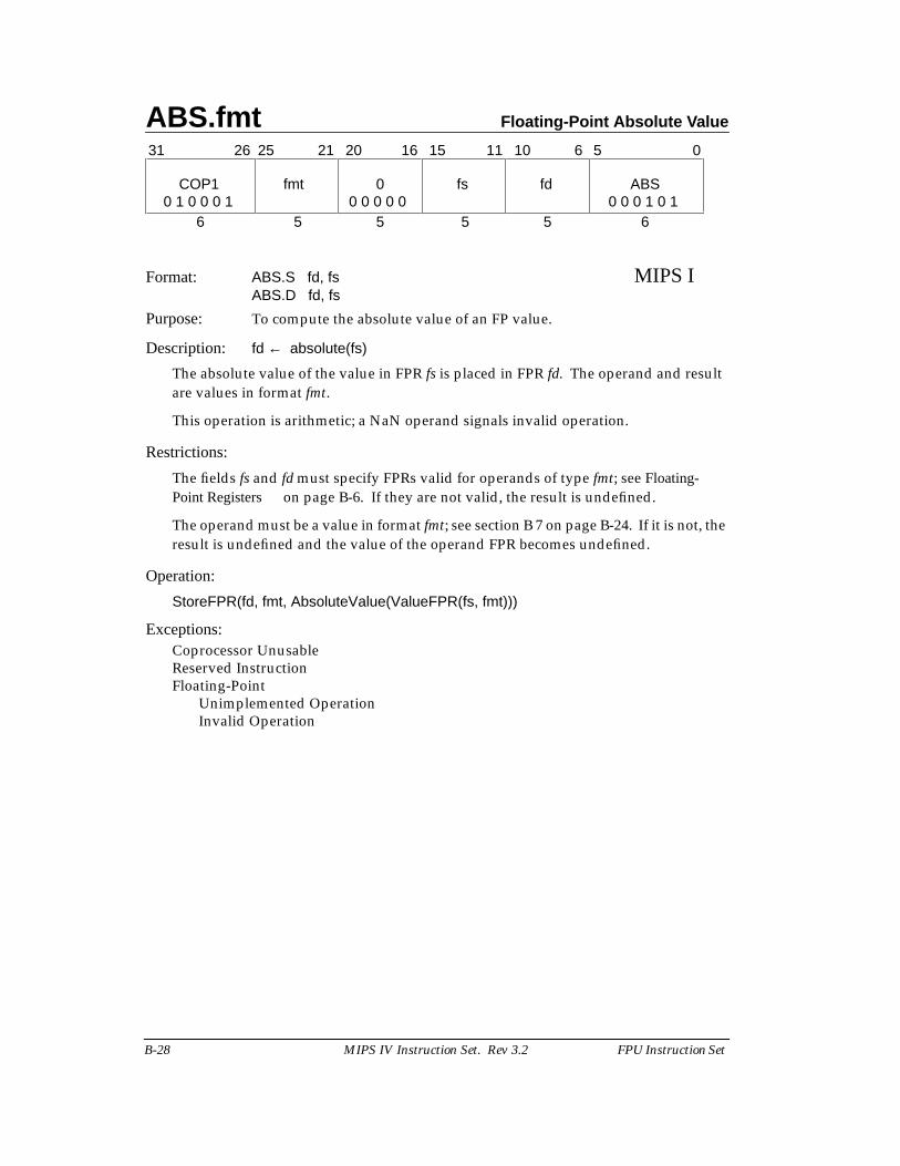
ABS.fmt Floating-Point Absolute Value
B-28 MIPS IV Instruction Set. Rev 3.2 FPU Instruction Set
Format: ABS.S fd, fs MIPS IABS.D fd, fs
Purpose: To compute the absolute value of an FP value.
Description: fd ← absolute(fs)
The absolute value of the value in FPR fs is placed in FPR fd. The operand and resultare values in format fmt.
This operation is arithmetic; a NaN operand signals invalid operation.
Restrictions:
The fields fs and fd must specify FPRs valid for operands of type fmt; see Floating-Point Registers on page B-6. If they are not valid, the result is undefined.
The operand must be a value in format fmt; see section B 7 on page B-24. If it is not, theresult is undefined and the value of the operand FPR becomes undefined.
Operation:
StoreFPR(fd, fmt, AbsoluteValue(ValueFPR(fs, fmt)))
Exceptions:Coprocessor UnusableReserved InstructionFloating-Point
Unimplemented OperationInvalid Operation
31 0
6 5 5 5 5 6
COP1 fmt 0 fs fd ABS
11 1021 20 16 1526 25 6 5
0 1 0 0 0 1 0 0 0 0 0 0 0 0 1 0 1
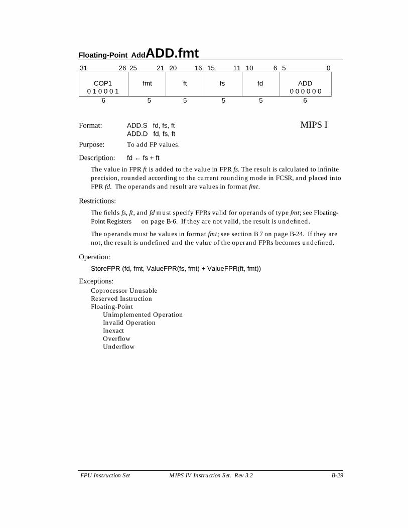
Floating-Point Add ADD.fmt
FPU Instruction Set MIPS IV Instruction Set. Rev 3.2 B-29
Format: ADD.S fd, fs, ft MIPS IADD.D fd, fs, ft
Purpose: To add FP values.
Description: fd ← fs + ft
The value in FPR ft is added to the value in FPR fs. The result is calculated to infiniteprecision, rounded according to the current rounding mode in FCSR, and placed intoFPR fd. The operands and result are values in format fmt.
Restrictions:
The fields fs, ft, and fd must specify FPRs valid for operands of type fmt; see Floating-Point Registers on page B-6. If they are not valid, the result is undefined.
The operands must be values in format fmt; see section B 7 on page B-24. If they arenot, the result is undefined and the value of the operand FPRs becomes undefined.
Operation:
StoreFPR (fd, fmt, ValueFPR(fs, fmt) + ValueFPR(ft, fmt))
Exceptions:Coprocessor UnusableReserved InstructionFloating-Point
Unimplemented OperationInvalid OperationInexactOverflowUnderflow
31 0
6 5 5 5 5 6
COP1 fmt ft fs fd ADD
11 1021 20 16 1526 25 6 5
0 1 0 0 0 1 0 0 0 0 0 0
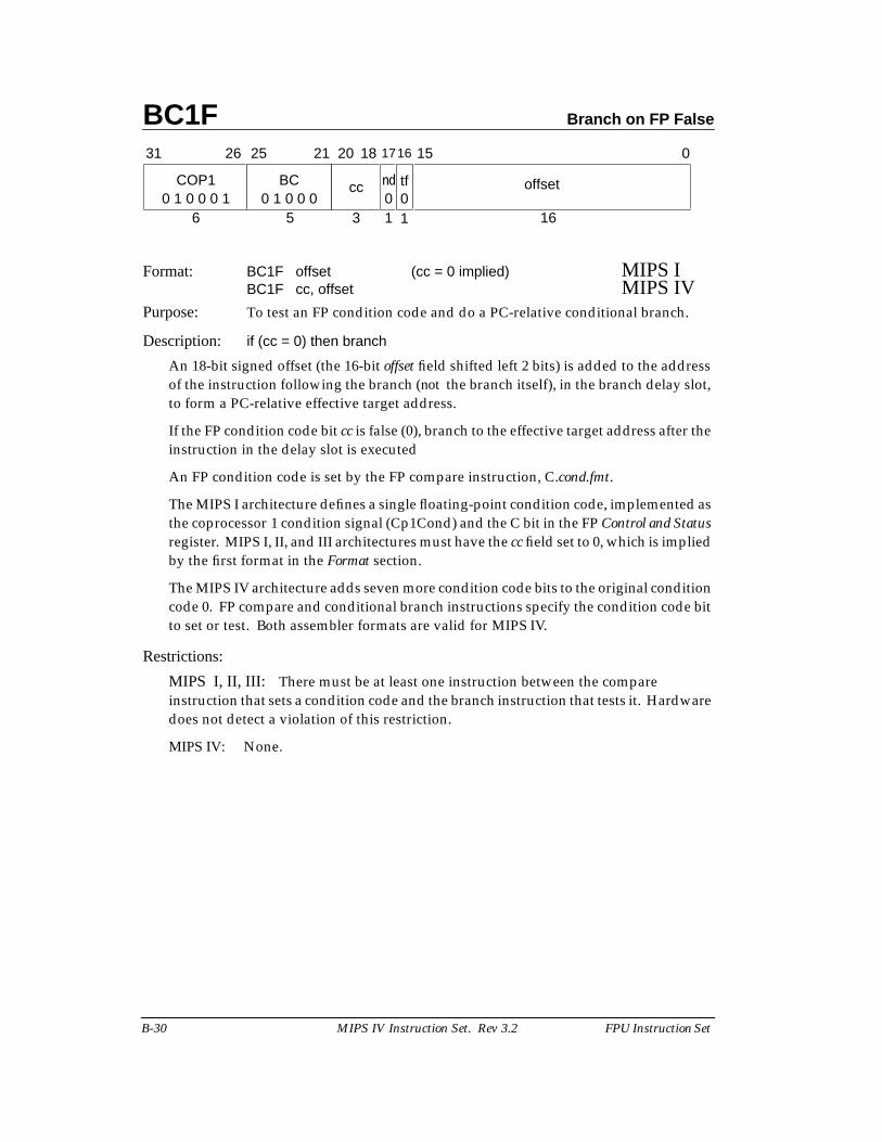
BC1F Branch on FP False
B-30 MIPS IV Instruction Set. Rev 3.2 FPU Instruction Set
Format: BC1F offset (cc = 0 implied) MIPS IBC1F cc, offset MIPS IV
Purpose: To test an FP condition code and do a PC-relative conditional branch.
Description: if (cc = 0) then branch
An 18-bit signed offset (the 16-bit offset field shifted left 2 bits) is added to the addressof the instruction following the branch (not the branch itself), in the branch delay slot,to form a PC-relative effective target address.
If the FP condition code bit cc is false (0), branch to the effective target address after theinstruction in the delay slot is executed
An FP condition code is set by the FP compare instruction, C.cond.fmt.
The MIPS I architecture defines a single floating-point condition code, implemented asthe coprocessor 1 condition signal (Cp1Cond) and the C bit in the FP Control and Statusregister. MIPS I, II, and III architectures must have the cc field set to 0, which is impliedby the first format in the Format section.
The MIPS IV architecture adds seven more condition code bits to the original conditioncode 0. FP compare and conditional branch instructions specify the condition code bitto set or test. Both assembler formats are valid for MIPS IV.
Restrictions:
MIPS I, II, III: There must be at least one instruction between the compareinstruction that sets a condition code and the branch instruction that tests it. Hardwaredoes not detect a violation of this restriction.
MIPS IV: None.
3
15
BC
31 2526
COP1
6
0
16
offsetnd
21 20
50 1 0 0 0 1 0 1 0 0 0 0
cc
1 10tf
18 1716
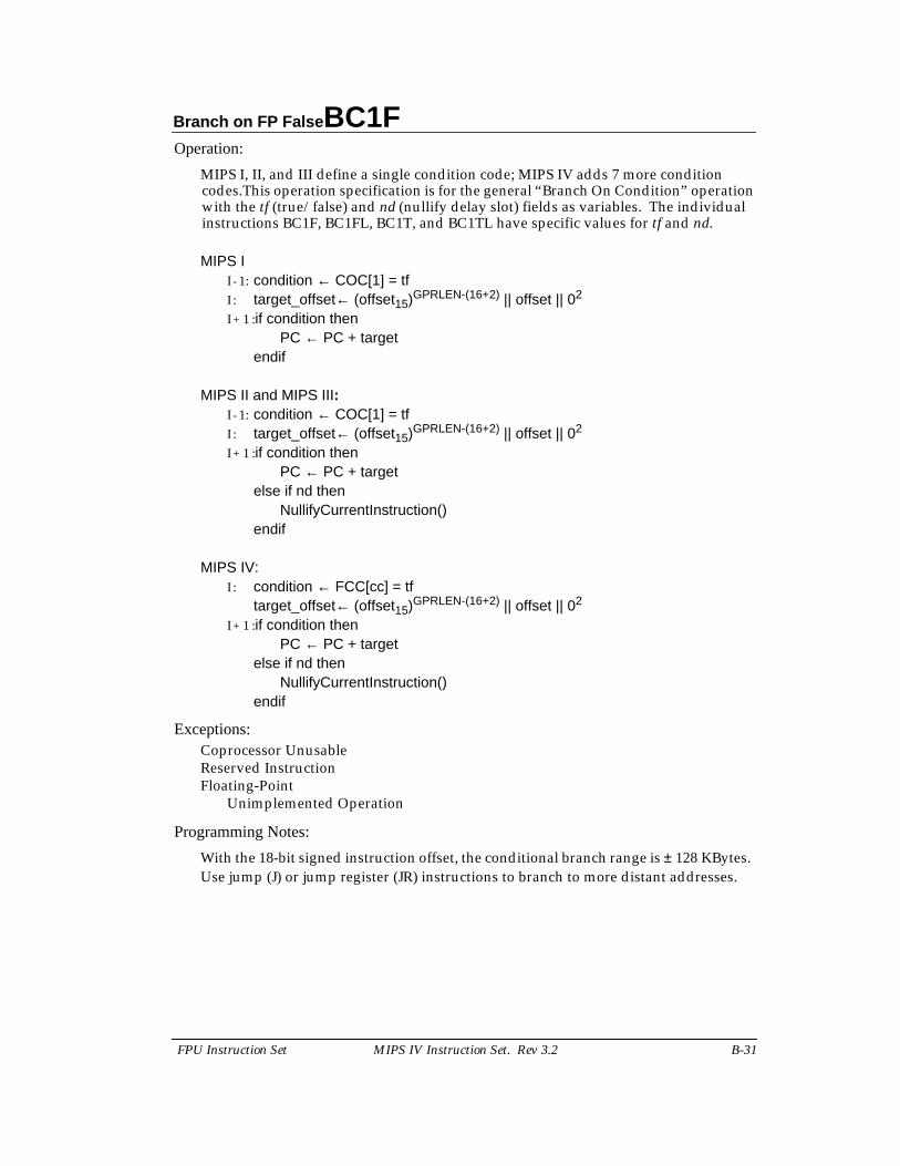
Branch on FP False BC1F
FPU Instruction Set MIPS IV Instruction Set. Rev 3.2 B-31
Operation:
MIPS I, II, and III define a single condition code; MIPS IV adds 7 more conditioncodes.This operation specification is for the general “Branch On Condition” operationwith the tf (true/false) and nd (nullify delay slot) fields as variables. The individualinstructions BC1F, BC1FL, BC1T, and BC1TL have specific values for tf and nd.
MIPS II - 1: condition ← COC[1] = tfI : target_offset← (offset15)GPRLEN-(16+2) || offset || 02
I + 1 :if condition thenPC ← PC + target
endif
MIPS II and MIPS III:I - 1: condition ← COC[1] = tfI : target_offset← (offset15)GPRLEN-(16+2) || offset || 02
I + 1 :if condition thenPC ← PC + target
else if nd thenNullifyCurrentInstruction()
endif
MIPS IV:I : condition ← FCC[cc] = tf
target_offset← (offset15)GPRLEN-(16+2) || offset || 02
I + 1 :if condition thenPC ← PC + target
else if nd thenNullifyCurrentInstruction()
endif
Exceptions:Coprocessor UnusableReserved InstructionFloating-Point
Unimplemented Operation
Programming Notes:
With the 18-bit signed instruction offset, the conditional branch range is ± 128 KBytes.Use jump (J) or jump register (JR) instructions to branch to more distant addresses.
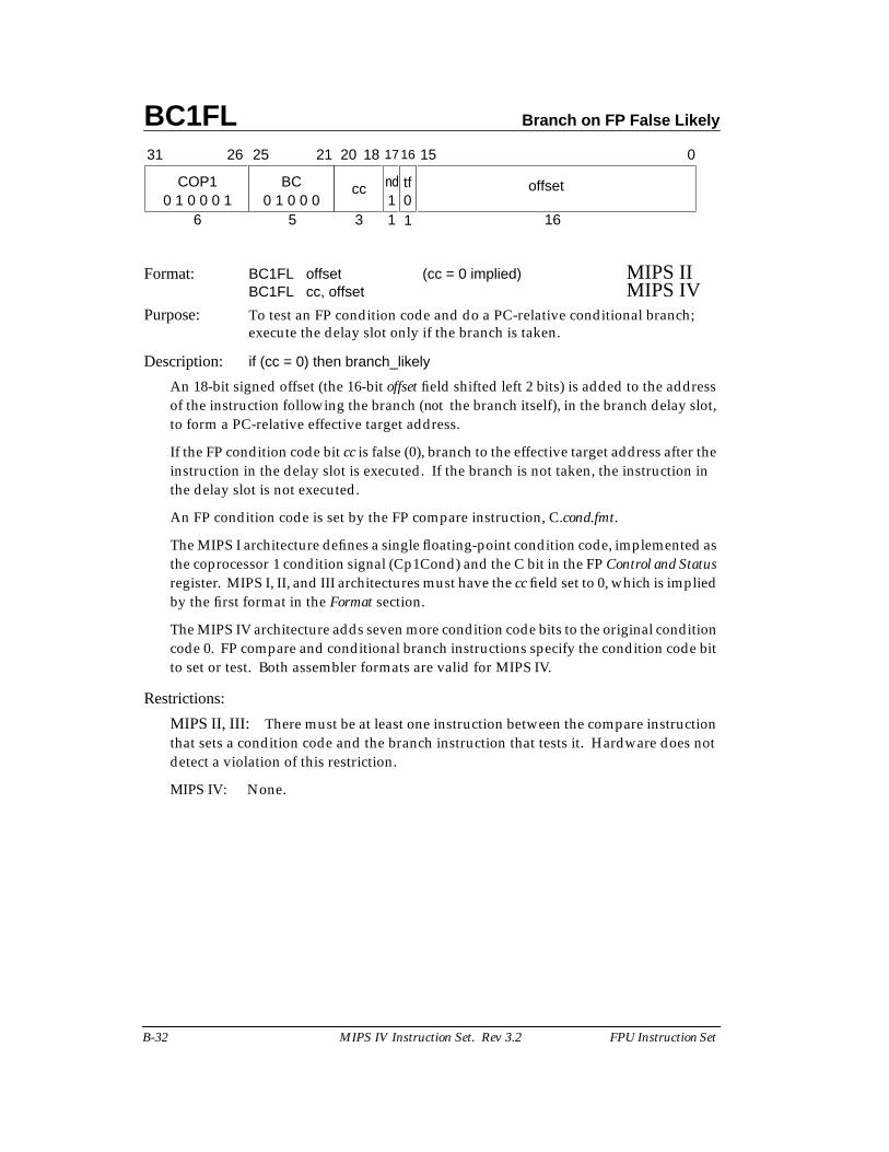
BC1FL Branch on FP False Likely
B-32 MIPS IV Instruction Set. Rev 3.2 FPU Instruction Set
Format: BC1FL offset (cc = 0 implied) MIPS IIBC1FL cc, offset MIPS IV
Purpose: To test an FP condition code and do a PC-relative conditional branch;execute the delay slot only if the branch is taken.
Description: if (cc = 0) then branch_likely
An 18-bit signed offset (the 16-bit offset field shifted left 2 bits) is added to the addressof the instruction following the branch (not the branch itself), in the branch delay slot,to form a PC-relative effective target address.
If the FP condition code bit cc is false (0), branch to the effective target address after theinstruction in the delay slot is executed. If the branch is not taken, the instruction inthe delay slot is not executed.
An FP condition code is set by the FP compare instruction, C.cond.fmt.
The MIPS I architecture defines a single floating-point condition code, implemented asthe coprocessor 1 condition signal (Cp1Cond) and the C bit in the FP Control and Statusregister. MIPS I, II, and III architectures must have the cc field set to 0, which is impliedby the first format in the Format section.
The MIPS IV architecture adds seven more condition code bits to the original conditioncode 0. FP compare and conditional branch instructions specify the condition code bitto set or test. Both assembler formats are valid for MIPS IV.
Restrictions:
MIPS II, III: There must be at least one instruction between the compare instructionthat sets a condition code and the branch instruction that tests it. Hardware does notdetect a violation of this restriction.
MIPS IV: None.
3
15
BC
31 2526
COP1
6
0
16
offsetnd
21 20
50 1 0 0 0 1 0 1 0 0 0 1
cc
1 10tf
18 1716
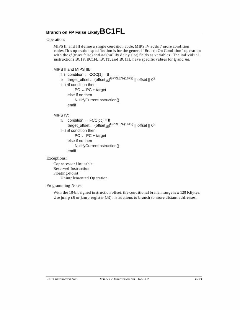
Branch on FP False Likely BC1FL
FPU Instruction Set MIPS IV Instruction Set. Rev 3.2 B-33
Operation:
MIPS II, and III define a single condition code; MIPS IV adds 7 more conditioncodes.This operation specification is for the general “Branch On Condition” operationwith the tf (true/false) and nd (nullify delay slot) fields as variables. The individualinstructions BC1F, BC1FL, BC1T, and BC1TL have specific values for tf and nd.
MIPS II and MIPS III:I - 1: condition ← COC[1] = tfI : target_offset← (offset15)GPRLEN-(16+2) || offset || 02
I + 1 :if condition thenPC ← PC + target
else if nd thenNullifyCurrentInstruction()
endif
MIPS IV:I : condition ← FCC[cc] = tf
target_offset← (offset15)GPRLEN-(16+2) || offset || 02
I + 1 :if condition thenPC ← PC + target
else if nd thenNullifyCurrentInstruction()
endif
Exceptions:Coprocessor UnusableReserved InstructionFloating-Point
Unimplemented Operation
Programming Notes:
With the 18-bit signed instruction offset, the conditional branch range is ± 128 KBytes.Use jump (J) or jump register (JR) instructions to branch to more distant addresses.

BC1T Branch on FP True
B-34 MIPS IV Instruction Set. Rev 3.2 FPU Instruction Set
Format: BC1T offset (cc = 0 implied) MIPS IBC1T cc, offset MIPS IV
Purpose: To test an FP condition code and do a PC-relative conditional branch.
Description: if (cc = 1) then branch
An 18-bit signed offset (the 16-bit offset field shifted left 2 bits) is added to the addressof the instruction following the branch (not the branch itself), in the branch delay slot,to form a PC-relative effective target address.
If the FP condition code bit cc is true (1), branch to the effective target address after theinstruction in the delay slot is executed
An FP condition code is set by the FP compare instruction, C.cond.fmt.
The MIPS I architecture defines a single floating-point condition code, implemented asthe coprocessor 1 condition signal (Cp1Cond) and the C bit in the FP Control and Statusregister. MIPS I, II, and III architectures must have the cc field set to 0, which is impliedby the first format in the Format section.
The MIPS IV architecture adds seven more condition code bits to the original conditioncode 0. FP compare and conditional branch instructions specify the condition code bitto set or test. Both assembler formats are valid for MIPS IV.
Restrictions:
MIPS I, II, III: There must be at least one instruction between the compareinstruction that sets a condition code and the branch instruction that tests it. Hardwaredoes not detect a violation of this restriction.
MIPS IV: None
3
15
BC
31 2526
COP1
6
0
16
offsetnd
21 20
50 1 0 0 0 1 0 1 0 0 0 0
cc
1 11tf
18 1716
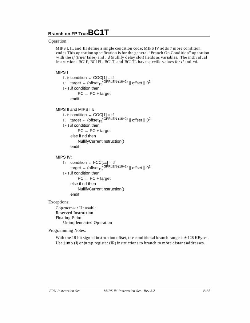
Branch on FP True BC1T
FPU Instruction Set MIPS IV Instruction Set. Rev 3.2 B-35
Operation:
MIPS I, II, and III define a single condition code; MIPS IV adds 7 more conditioncodes.This operation specification is for the general “Branch On Condition” operationwith the tf (true/false) and nd (nullify delay slot) fields as variables. The individualinstructions BC1F, BC1FL, BC1T, and BC1TL have specific values for tf and nd.
MIPS II - 1: condition ← COC[1] = tfI : target ← (offset15)GPRLEN-(16+2) || offset || 02
I + 1 :if condition thenPC ← PC + target
endif
MIPS II and MIPS III:I - 1: condition ← COC[1] = tfI : target ← (offset15)GPRLEN-(16+2) || offset || 02
I + 1 :if condition thenPC ← PC + target
else if nd thenNullifyCurrentInstruction()
endif
MIPS IV:I : condition ← FCC[cc] = tf
target ← (offset15)GPRLEN-(16+2) || offset || 02
I + 1 :if condition thenPC ← PC + target
else if nd thenNullifyCurrentInstruction()
endif
Exceptions:Coprocessor UnusableReserved InstructionFloating-Point
Unimplemented Operation
Programming Notes:
With the 18-bit signed instruction offset, the conditional branch range is ± 128 KBytes.Use jump (J) or jump register (JR) instructions to branch to more distant addresses.
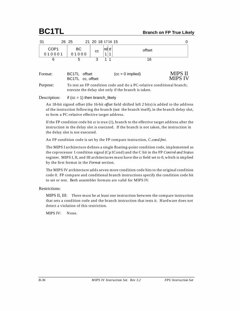
BC1TL Branch on FP True Likely
B-36 MIPS IV Instruction Set. Rev 3.2 FPU Instruction Set
Format: BC1TL offset (cc = 0 implied) MIPS IIBC1TL cc, offset MIPS IV
Purpose: To test an FP condition code and do a PC-relative conditional branch;execute the delay slot only if the branch is taken.
Description: if (cc = 1) then branch_likely
An 18-bit signed offset (the 16-bit offset field shifted left 2 bits) is added to the addressof the instruction following the branch (not the branch itself), in the branch delay slot,to form a PC-relative effective target address.
If the FP condition code bit cc is true (1), branch to the effective target address after theinstruction in the delay slot is executed. If the branch is not taken, the instruction inthe delay slot is not executed.
An FP condition code is set by the FP compare instruction, C.cond.fmt.
The MIPS I architecture defines a single floating-point condition code, implemented asthe coprocessor 1 condition signal (Cp1Cond) and the C bit in the FP Control and Statusregister. MIPS I, II, and III architectures must have the cc field set to 0, which is impliedby the first format in the Format section.
The MIPS IV architecture adds seven more condition code bits to the original conditioncode 0. FP compare and conditional branch instructions specify the condition code bitto set or test. Both assembler formats are valid for MIPS IV.
Restrictions:
MIPS II, III: There must be at least one instruction between the compare instructionthat sets a condition code and the branch instruction that tests it. Hardware does notdetect a violation of this restriction.
MIPS IV: None.
3
15
BC
31 2526
COP1
6
0
16
offsetnd
21 20
50 1 0 0 0 1 0 1 0 0 0 1
cc
1 11tf
18 1716
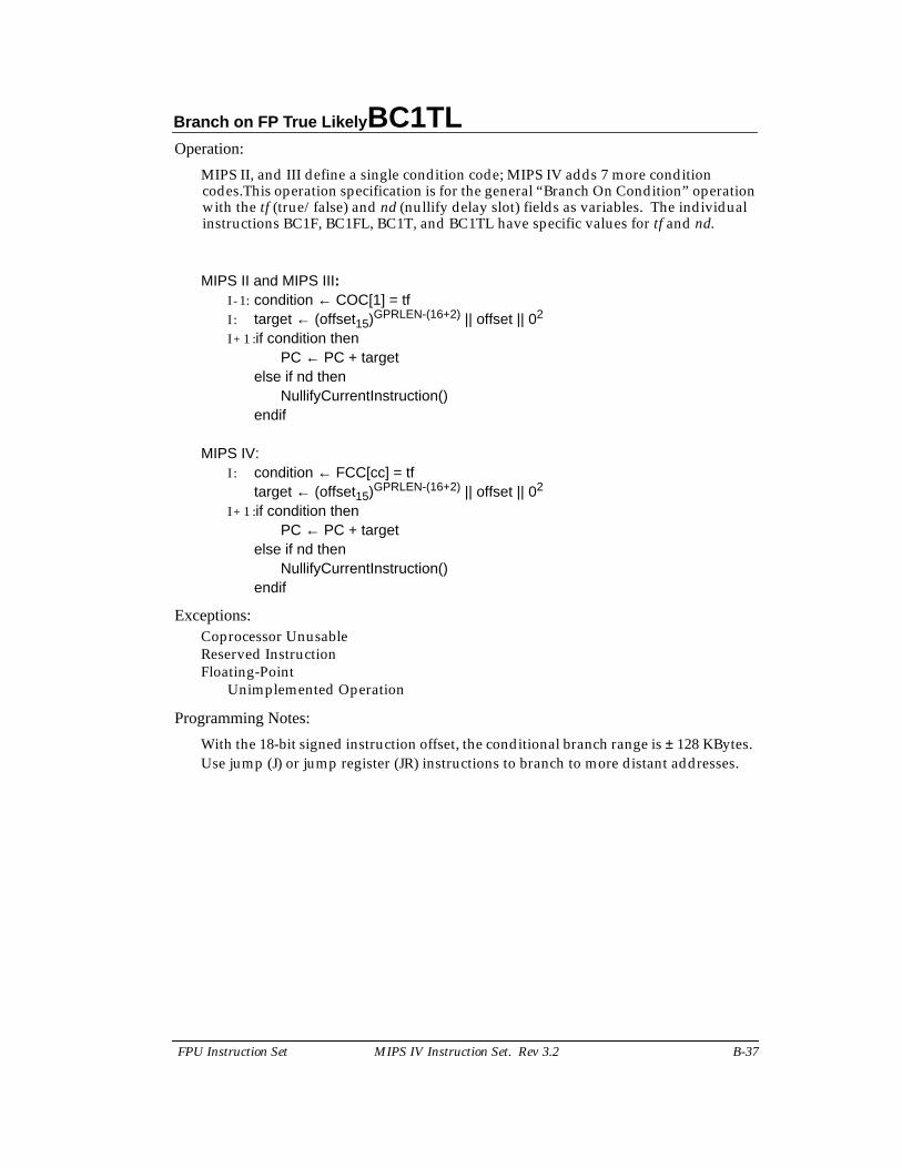
Branch on FP True Likely BC1TL
FPU Instruction Set MIPS IV Instruction Set. Rev 3.2 B-37
Operation:
MIPS II, and III define a single condition code; MIPS IV adds 7 more conditioncodes.This operation specification is for the general “Branch On Condition” operationwith the tf (true/false) and nd (nullify delay slot) fields as variables. The individualinstructions BC1F, BC1FL, BC1T, and BC1TL have specific values for tf and nd.
MIPS II and MIPS III:I - 1: condition ← COC[1] = tfI : target ← (offset15)GPRLEN-(16+2) || offset || 02
I + 1 :if condition thenPC ← PC + target
else if nd thenNullifyCurrentInstruction()
endif
MIPS IV:I : condition ← FCC[cc] = tf
target ← (offset15)GPRLEN-(16+2) || offset || 02
I + 1 :if condition thenPC ← PC + target
else if nd thenNullifyCurrentInstruction()
endif
Exceptions:Coprocessor UnusableReserved InstructionFloating-Point
Unimplemented Operation
Programming Notes:
With the 18-bit signed instruction offset, the conditional branch range is ± 128 KBytes.Use jump (J) or jump register (JR) instructions to branch to more distant addresses.
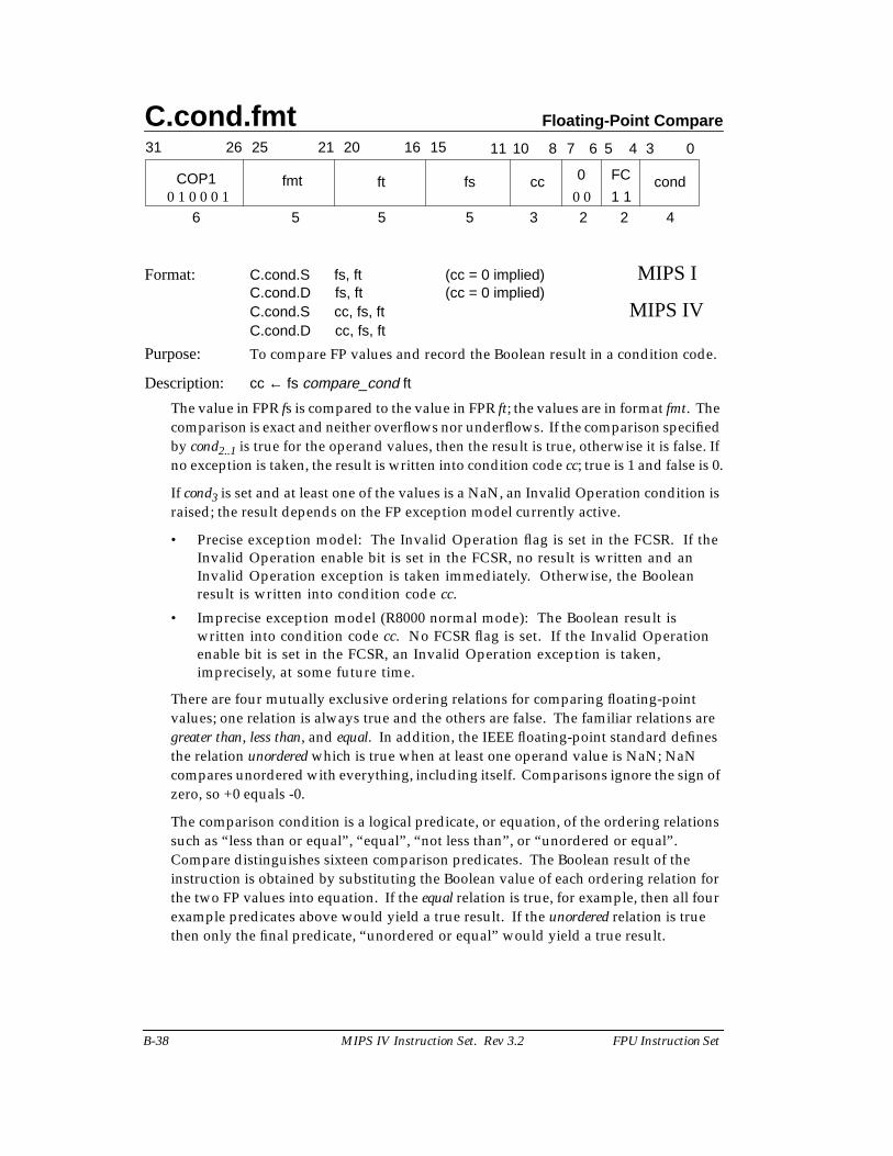
C.cond.fmt Floating-Point Compare
B-38 MIPS IV Instruction Set. Rev 3.2 FPU Instruction Set
Format: C.cond.S fs, ft (cc = 0 implied) MIPS IC.cond.D fs, ft (cc = 0 implied)C.cond.S cc, fs, ft MIPS IVC.cond.D cc, fs, ft
Purpose: To compare FP values and record the Boolean result in a condition code.
Description: cc ← fs compare_cond ft
The value in FPR fs is compared to the value in FPR ft; the values are in format fmt. Thecomparison is exact and neither overflows nor underflows. If the comparison specifiedby cond2..1 is true for the operand values, then the result is true, otherwise it is false. Ifno exception is taken, the result is written into condition code cc; true is 1 and false is 0.
If cond3 is set and at least one of the values is a NaN, an Invalid Operation condition israised; the result depends on the FP exception model currently active.
• Precise exception model: The Invalid Operation flag is set in the FCSR. If theInvalid Operation enable bit is set in the FCSR, no result is written and anInvalid Operation exception is taken immediately. Otherwise, the Booleanresult is written into condition code cc.
• Imprecise exception model (R8000 normal mode): The Boolean result iswritten into condition code cc. No FCSR flag is set. If the Invalid Operationenable bit is set in the FCSR, an Invalid Operation exception is taken,imprecisely, at some future time.
There are four mutually exclusive ordering relations for comparing floating-pointvalues; one relation is always true and the others are false. The familiar relations aregreater than, less than, and equal. In addition, the IEEE floating-point standard definesthe relation unordered which is true when at least one operand value is NaN; NaNcompares unordered with everything, including itself. Comparisons ignore the sign ofzero, so +0 equals -0.
The comparison condition is a logical predicate, or equation, of the ordering relationssuch as “less than or equal”, “equal”, “not less than”, or “unordered or equal”.Compare distinguishes sixteen comparison predicates. The Boolean result of theinstruction is obtained by substituting the Boolean value of each ordering relation forthe two FP values into equation. If the equal relation is true, for example, then all fourexample predicates above would yield a true result. If the unordered relation is truethen only the final predicate, “unordered or equal” would yield a true result.
31 2526 2021 1516 0
COP1
6 5 5
346 58 71011
42235
ft fs cc 0 FC condfmt0 1 0 0 0 1 1 10 0
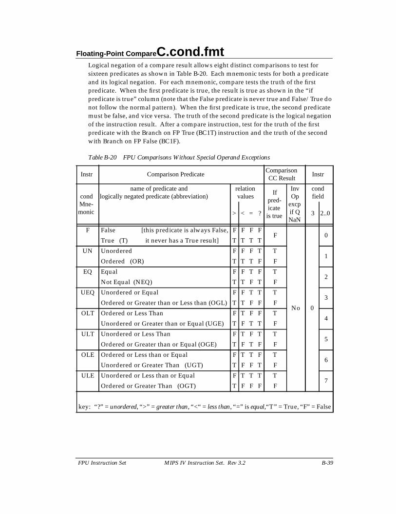
Floating-Point Compare C.cond.fmt
FPU Instruction Set MIPS IV Instruction Set. Rev 3.2 B-39
Logical negation of a compare result allows eight distinct comparisons to test forsixteen predicates as shown in Table B-20. Each mnemonic tests for both a predicateand its logical negation. For each mnemonic, compare tests the truth of the firstpredicate. When the first predicate is true, the result is true as shown in the “ifpredicate is true” column (note that the False predicate is never true and False/True donot follow the normal pattern). When the first predicate is true, the second predicatemust be false, and vice versa. The truth of the second predicate is the logical negationof the instruction result. After a compare instruction, test for the truth of the firstpredicate with the Branch on FP True (BC1T) instruction and the truth of the secondwith Branch on FP False (BC1F).
Table B-20 FPU Comparisons Without Special Operand Exceptions
Instr Comparison PredicateComparisonCC Result
Instr
condMne-monic
name of predicate andlogically negated predicate (abbreviation)
relationvalues
If pred-icate
is true
InvOp
excpif QNaN
condfield
> < = ? 3 2..0
F False [this predicate is always False, F F F FF
No 0
0True (T) it never has a True result] T T T T
UN Unordered F F F T T1
Ordered (OR) T T T F F
EQ Equal F F T F T2
Not Equal (NEQ) T T F T F
UEQ Unordered or Equal F F T T T3
Ordered or Greater than or Less than (OGL) T T F F F
OLT Ordered or Less Than F T F F T4
Unordered or Greater than or Equal (UGE) T F T T F
ULT Unordered or Less Than F T F T T5
Ordered or Greater than or Equal (OGE) T F T F F
OLE Ordered or Less than or Equal F T T F T6
Unordered or Greater Than (UGT) T F F T F
ULE Unordered or Less than or Equal F T T T T7
Ordered or Greater Than (OGT) T F F F F
key: “?” = unordered, “>” = greater than, “<“ = less than, “=” is equal,“T” = True, “F” = False
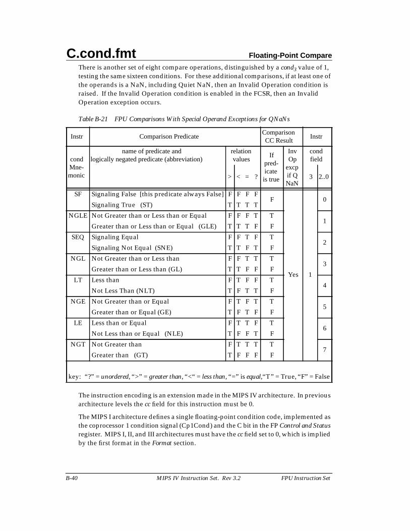
C.cond.fmt Floating-Point Compare
B-40 MIPS IV Instruction Set. Rev 3.2 FPU Instruction Set
There is another set of eight compare operations, distinguished by a cond3 value of 1,testing the same sixteen conditions. For these additional comparisons, if at least one ofthe operands is a NaN, including Quiet NaN, then an Invalid Operation condition israised. If the Invalid Operation condition is enabled in the FCSR, then an InvalidOperation exception occurs.
Table B-21 FPU Comparisons With Special Operand Exceptions for QNaNs
The instruction encoding is an extension made in the MIPS IV architecture. In previousarchitecture levels the cc field for this instruction must be 0.
The MIPS I architecture defines a single floating-point condition code, implemented asthe coprocessor 1 condition signal (Cp1Cond) and the C bit in the FP Control and Statusregister. MIPS I, II, and III architectures must have the cc field set to 0, which is impliedby the first format in the Format section.
Instr Comparison PredicateComparisonCC Result
Instr
condMne-monic
name of predicate andlogically negated predicate (abbreviation)
relationvalues
If pred-icate
is true
InvOp
excpif QNaN
condfield
> < = ? 3 2..0
SF Signaling False [this predicate always False] F F F FF
Yes 1
0Signaling True (ST) T T T T
NGLE Not Greater than or Less than or Equal F F F T T1
Greater than or Less than or Equal (GLE) T T T F F
SEQ Signaling Equal F F T F T2
Signaling Not Equal (SNE) T T F T F
NGL Not Greater than or Less than F F T T T3
Greater than or Less than (GL) T T F F F
LT Less than F T F F T4
Not Less Than (NLT) T F T T F
NGE Not Greater than or Equal F T F T T5
Greater than or Equal (GE) T F T F F
LE Less than or Equal F T T F T6
Not Less than or Equal (NLE) T F F T F
NGT Not Greater than F T T T T7
Greater than (GT) T F F F F
key: “?” = unordered, “>” = greater than, “<“ = less than, “=” is equal,“T” = True, “F” = False
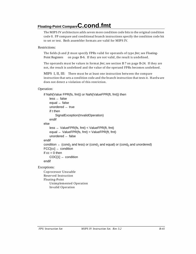
Floating-Point Compare C.cond.fmt
FPU Instruction Set MIPS IV Instruction Set. Rev 3.2 B-41
The MIPS IV architecture adds seven more condition code bits to the original conditioncode 0. FP compare and conditional branch instructions specify the condition code bitto set or test. Both assembler formats are valid for MIPS IV.
Restrictions:
The fields fs and ft must specify FPRs valid for operands of type fmt; see Floating-Point Registers on page B-6. If they are not valid, the result is undefined.
The operands must be values in format fmt; see section B 7 on page B-24. If they arenot, the result is undefined and the value of the operand FPRs becomes undefined.
MIPS I, II, III: There must be at least one instruction between the compareinstruction that sets a condition code and the branch instruction that tests it. Hardwaredoes not detect a violation of this restriction.
Operation:
if NaN(Value FPR(fs, fmt)) or NaN(ValueFPR(ft, fmt)) thenless ← falseequal ← falseunordered ← trueif t then
SignalException(InvalidOperation)endif
elseless ← ValueFPR(fs, fmt) < ValueFPR(ft, fmt)equal ← ValueFPR(fs, fmt) = ValueFPR(ft, fmt)unordered ← false
endifcondition ← (cond2 and less) or (cond1 and equal) or (cond0 and unordered)FCC[cc] ← conditionif cc = 0 then
COC[1] ← conditionendif
Exceptions:Coprocessor UnusableReserved InstructionFloating-Point
Unimplemented OperationInvalid Operation
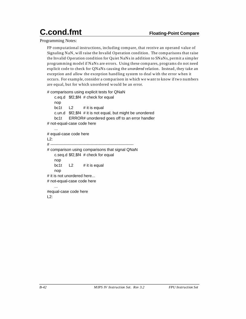
C.cond.fmt Floating-Point Compare
B-42 MIPS IV Instruction Set. Rev 3.2 FPU Instruction Set
Programming Notes:
FP computational instructions, including compare, that receive an operand value ofSignaling NaN, will raise the Invalid Operation condition. The comparisons that raisethe Invalid Operation condition for Quiet NaNs in addition to SNaNs, permit a simplerprogramming model if NaNs are errors. Using these compares, programs do not needexplicit code to check for QNaNs causing the unordered relation. Instead, they take anexception and allow the exception handling system to deal with the error when itoccurs. For example, consider a comparison in which we want to know if two numbersare equal, but for which unordered would be an error.
# comparisons using explicit tests for QNaNc.eq.d $f2,$f4 # check for equalnopbc1t L2 # it is equalc.un.d $f2,$f4 # it is not equal, but might be unorderedbc1t ERROR# unordered goes off to an error handler
# not-equal-case code here...
# equal-case code hereL2:# --------------------------------------------------------------# comparison using comparisons that signal QNaN
c.seq.d $f2,$f4 # check for equalnopbc1t L2 # it is equalnop
# it is not unordered here...# not-equal-case code here
...#equal-case code hereL2:

Floating-Point Ceiling Convert to Long Fixed-Point CEIL.L.fmt
FPU Instruction Set MIPS IV Instruction Set. Rev 3.2 B-43
Format: CEIL.L.S fd, fs MIPS IIICEIL.L.D fd, fs
Purpose: To convert an FP value to 64-bit fixed-point, rounding up.
Description: fd ← convert_and_round(fs)
The value in FPR fs in format fmt, is converted to a value in 64-bit long fixed-pointformat rounding toward +∞ (rounding mode 2). The result is placed in FPR fd.
When the source value is Infinity, NaN, or rounds to an integer outside the range-263 to 263-1, the result cannot be represented correctly and an IEEE Invalid Operationcondition exists. The result depends on the FP exception model currently active.
• Precise exception model: The Invalid Operation flag is set in the FCSR. If theInvalid Operation enable bit is set in the FCSR, no result is written to fd and anInvalid Operation exception is taken immediately. Otherwise, the defaultresult, 263–1, is written to fd.
• Imprecise exception model (R8000 normal mode): The default result, 263–1, iswritten to fd. No FCSR flag is set. If the Invalid Operation enable bit is set inthe FCSR, an Invalid Operation exception is taken, imprecisely, at some futuretime.
Restrictions:
The fields fs and fd must specify valid FPRs; fs for type fmt and fd for long fixed-point;see Floating-Point Registers on page B-6. If they are not valid, the result isundefined.
The operand must be a value in format fmt; see section B 7 on page B-24. If it is not, theresult is undefined and the value of the operand FPR becomes undefined.
Operation:
StoreFPR(fd, L, ConvertFmt(ValueFPR(fs, fmt), fmt, L))
Exceptions:Coprocessor UnusableReserved InstructionFloating-Point
Invalid Operation Unimplemented OperationInexact Overflow
31 0
6 5 5 5 5 6
COP1 fmt 0 fs fd CEIL.L
11 1021 20 16 1526 25 6 5
0 1 0 0 0 1 0 0 0 0 0 0 0 1 0 1 0

CEIL.W.fmt Floating-Point Ceiling Convert to Word Fixed-Point
B-44 MIPS IV Instruction Set. Rev 3.2 FPU Instruction Set
Format: CEIL.W.S fd, fs MIPS IICEIL.W.D fd, fs
Purpose: To convert an FP value to 32-bit fixed-point, rounding up.
Description: fd ← convert_and_round(fs)
The value in FPR fs in format fmt, is converted to a value in 32-bit word fixed-pointformat rounding toward +∞ (rounding mode 2). The result is placed in FPR fd.
When the source value is Infinity, NaN, or rounds to an integer outside the range-231 to 231-1, the result cannot be represented correctly and an IEEE Invalid Operationcondition exists. The result depends on the FP exception model currently active.
• Precise exception model: The Invalid Operation flag is set in the FCSR. If theInvalid Operation enable bit is set in the FCSR, no result is written to fd and anInvalid Operation exception is taken immediately. Otherwise, the defaultresult, 231–1, is written to fd.
• Imprecise exception model (R8000 normal mode): The default result, 231–1, iswritten to fd. No FCSR flag is set. If the Invalid Operation enable bit is set inthe FCSR, an Invalid Operation exception is taken, imprecisely, at some futuretime.
Restrictions:
The fields fs and fd must specify valid FPRs; fs for type fmt and fd for word fixed-point;see Floating-Point Registers on page B-6. If they are not valid, the result isundefined.
The operand must be a value in format fmt; see section B 7 on page B-24. If it is not, theresult is undefined and the value of the operand FPR becomes undefined.
Operation:
StoreFPR(fd, W, ConvertFmt(ValueFPR(fs, fmt), fmt, W))
Exceptions:Coprocessor UnusableReserved InstructionFloating-Point
Invalid OperationUnimplemented OperationInexactOverflow
31 0
6 5 5 5 5 6
COP1 fmt 0 fs fd CEIL.W
11 1021 20 16 1526 25 6 5
0 1 0 0 0 1 0 0 0 0 0 0 0 1 1 1 0
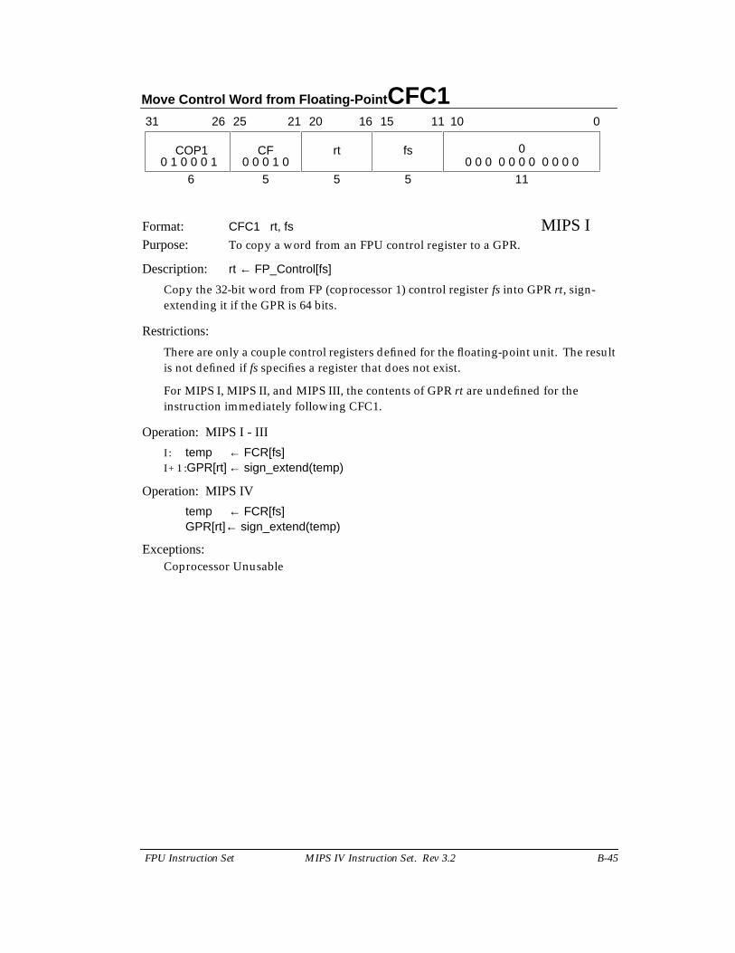
Move Control Word from Floating-Point CFC1
FPU Instruction Set MIPS IV Instruction Set. Rev 3.2 B-45
Format: CFC1 rt, fs MIPS IPurpose: To copy a word from an FPU control register to a GPR.
Description: rt ← FP_Control[fs]
Copy the 32-bit word from FP (coprocessor 1) control register fs into GPR rt, sign-extending it if the GPR is 64 bits.
Restrictions:
There are only a couple control registers defined for the floating-point unit. The resultis not defined if fs specifies a register that does not exist.
For MIPS I, MIPS II, and MIPS III, the contents of GPR rt are undefined for theinstruction immediately following CFC1.
Operation: MIPS I - III
I : temp ← FCR[fs]I + 1 :GPR[rt] ← sign_extend(temp)
Operation: MIPS IV
temp ← FCR[fs]GPR[rt]← sign_extend(temp)
Exceptions:Coprocessor Unusable
11
31 2526 2021 1516
COP1 CF rt
6 5 5
fs 0
5
11 10 0
0 1 0 0 0 1 0 0 0 1 0 0 0 0 0 0 0 0 0 0 0 0
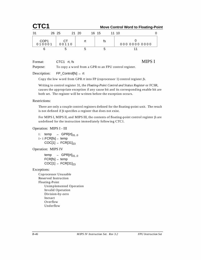
CTC1 Move Control Word to Floating-Point
B-46 MIPS IV Instruction Set. Rev 3.2 FPU Instruction Set
Format: CTC1 rt, fs MIPS IPurpose: To copy a word from a GPR to an FPU control register.
Description: FP_Control[fs] ← rt
Copy the low word from GPR rt into FP (coprocessor 1) control register fs.
Writing to control register 31, the Floating-Point Control and Status Register or FCSR,causes the appropriate exception if any cause bit and its corresponding enable bit areboth set. The register will be written before the exception occurs.
Restrictions:
There are only a couple control registers defined for the floating-point unit. The resultis not defined if fs specifies a register that does not exist.
For MIPS I, MIPS II, and MIPS III, the contents of floating-point control register fs areundefined for the instruction immediately following CTC1.
Operation: MIPS I - III
I : temp ← GPR[rt]31..0I + 1 :FCR[fs]← temp
COC[1] ← FCR[31]23
Operation: MIPS IV
temp ← GPR[rt]31..0FCR[fs] ← tempCOC[1] ← FCR[31]23
Exceptions:Coprocessor UnusableReserved InstructionFloating-Point
Unimplemented OperationInvalid OperationDivision-by-zeroInexactOverflowUnderflow
11
31 2526 2021 1516
COP1 CT rt
6 5 5
fs 0
5
11 10 0
0 1 0 0 0 1 0 0 1 1 0 0 0 0 0 0 0 0 0 0 0 0
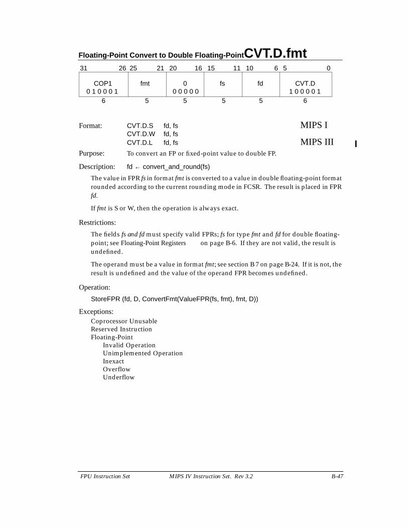
Floating-Point Convert to Double Floating-Point CVT.D.fmt
FPU Instruction Set MIPS IV Instruction Set. Rev 3.2 B-47
Format: CVT.D.S fd, fs MIPS ICVT.D.W fd, fsCVT.D.L fd, fs MIPS III
Purpose: To convert an FP or fixed-point value to double FP.
Description: fd ← convert_and_round(fs)
The value in FPR fs in format fmt is converted to a value in double floating-point formatrounded according to the current rounding mode in FCSR. The result is placed in FPRfd.
If fmt is S or W, then the operation is always exact.
Restrictions:
The fields fs and fd must specify valid FPRs; fs for type fmt and fd for double floating-point; see Floating-Point Registers on page B-6. If they are not valid, the result isundefined.
The operand must be a value in format fmt; see section B 7 on page B-24. If it is not, theresult is undefined and the value of the operand FPR becomes undefined.
Operation:
StoreFPR (fd, D, ConvertFmt(ValueFPR(fs, fmt), fmt, D))
Exceptions:Coprocessor UnusableReserved InstructionFloating-Point
Invalid OperationUnimplemented OperationInexactOverflowUnderflow
31 0
6 5 5 5 5 6
COP1 fmt 0 fs fd CVT.D
11 1021 20 16 1526 25 6 5
0 1 0 0 0 1 1 0 0 0 0 10 0 0 0 0
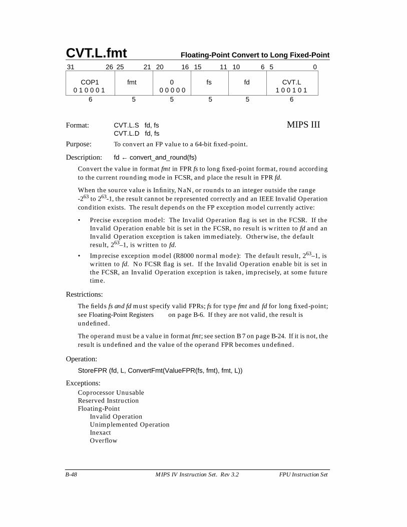
CVT.L.fmt Floating-Point Convert to Long Fixed-Point
B-48 MIPS IV Instruction Set. Rev 3.2 FPU Instruction Set
Format: CVT.L.S fd, fs MIPS IIICVT.L.D fd, fs
Purpose: To convert an FP value to a 64-bit fixed-point.
Description: fd ← convert_and_round(fs)
Convert the value in format fmt in FPR fs to long fixed-point format, round accordingto the current rounding mode in FCSR, and place the result in FPR fd.
When the source value is Infinity, NaN, or rounds to an integer outside the range-263 to 263-1, the result cannot be represented correctly and an IEEE Invalid Operationcondition exists. The result depends on the FP exception model currently active:
• Precise exception model: The Invalid Operation flag is set in the FCSR. If theInvalid Operation enable bit is set in the FCSR, no result is written to fd and anInvalid Operation exception is taken immediately. Otherwise, the defaultresult, 263–1, is written to fd.
• Imprecise exception model (R8000 normal mode): The default result, 263–1, iswritten to fd. No FCSR flag is set. If the Invalid Operation enable bit is set inthe FCSR, an Invalid Operation exception is taken, imprecisely, at some futuretime.
Restrictions:
The fields fs and fd must specify valid FPRs; fs for type fmt and fd for long fixed-point;see Floating-Point Registers on page B-6. If they are not valid, the result isundefined.
The operand must be a value in format fmt; see section B 7 on page B-24. If it is not, theresult is undefined and the value of the operand FPR becomes undefined.
Operation:
StoreFPR (fd, L, ConvertFmt(ValueFPR(fs, fmt), fmt, L))
Exceptions:Coprocessor UnusableReserved InstructionFloating-Point
Invalid OperationUnimplemented OperationInexactOverflow
31 0
6 5 5 5 5 6
COP1 fmt 0 fs fd CVT.L
11 1021 20 16 1526 25 6 5
0 1 0 0 0 1 1 0 0 1 0 10 0 0 0 0
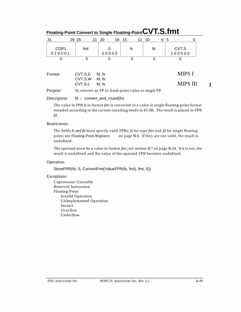
Floating-Point Convert to Single Floating-Point CVT.S.fmt
FPU Instruction Set MIPS IV Instruction Set. Rev 3.2 B-49
Format: CVT.S.D fd, fs MIPS ICVT.S.W fd, fsCVT.S.L fd, fs MIPS III
Purpose: To convert an FP or fixed-point value to single FP.
Description: fd ← convert_and_round(fs)
The value in FPR fs in format fmt is converted to a value in single floating-point formatrounded according to the current rounding mode in FCSR. The result is placed in FPRfd.
Restrictions:
The fields fs and fd must specify valid FPRs; fs for type fmt and fd for single floating-point; see Floating-Point Registers on page B-6. If they are not valid, the result isundefined.
The operand must be a value in format fmt; see section B 7 on page B-24. If it is not, theresult is undefined and the value of the operand FPR becomes undefined.
Operation:
StoreFPR(fd, S, ConvertFmt(ValueFPR(fs, fmt), fmt, S))
Exceptions:Coprocessor UnusableReserved InstructionFloating-Point
Invalid OperationUnimplemented OperationInexactOverflowUnderflow
31 0
6 5 5 5 5 6
COP1 fmt 0 fs fd CVT.S
11 1021 20 16 1526 25 6 5
0 1 0 0 0 1 1 0 0 0 0 00 0 0 0 0
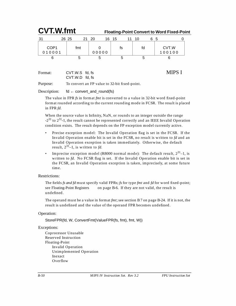
CVT.W.fmt Floating-Point Convert to Word Fixed-Point
B-50 MIPS IV Instruction Set. Rev 3.2 FPU Instruction Set
Format: CVT.W.S fd, fs MIPS ICVT.W.D fd, fs
Purpose: To convert an FP value to 32-bit fixed-point.
Description: fd ← convert_and_round(fs)
The value in FPR fs in format fmt is converted to a value in 32-bit word fixed-pointformat rounded according to the current rounding mode in FCSR. The result is placedin FPR fd.
When the source value is Infinity, NaN, or rounds to an integer outside the range-231 to 231-1, the result cannot be represented correctly and an IEEE Invalid Operationcondition exists. The result depends on the FP exception model currently active.
• Precise exception model: The Invalid Operation flag is set in the FCSR. If theInvalid Operation enable bit is set in the FCSR, no result is written to fd and anInvalid Operation exception is taken immediately. Otherwise, the defaultresult, 231–1, is written to fd.
• Imprecise exception model (R8000 normal mode): The default result, 231–1, iswritten to fd. No FCSR flag is set. If the Invalid Operation enable bit is set inthe FCSR, an Invalid Operation exception is taken, imprecisely, at some futuretime.
Restrictions:
The fields fs and fd must specify valid FPRs; fs for type fmt and fd for word fixed-point;see Floating-Point Registers on page B-6. If they are not valid, the result isundefined.
The operand must be a value in format fmt; see section B 7 on page B-24. If it is not, theresult is undefined and the value of the operand FPR becomes undefined.
Operation:
StoreFPR(fd, W, ConvertFmt(ValueFPR(fs, fmt), fmt, W))
Exceptions:Coprocessor UnusableReserved InstructionFloating-Point
Invalid OperationUnimplemented OperationInexactOverflow
31 0
6 5 5 5 5 6
COP1 fmt 0 fs fd CVT.W
11 1021 20 16 1526 25 6 5
0 1 0 0 0 1 1 0 0 1 0 00 0 0 0 0
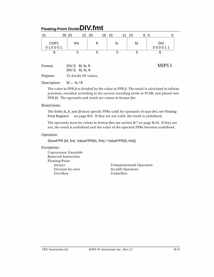
Floating-Point Divide DIV.fmt
FPU Instruction Set MIPS IV Instruction Set. Rev 3.2 B-51
Format: DIV.S fd, fs, ft MIPS IDIV.D fd, fs, ft
Purpose: To divide FP values.
Description: fd ← fs / ft
The value in FPR fs is divided by the value in FPR ft. The result is calculated to infiniteprecision, rounded according to the current rounding mode in FCSR, and placed intoFPR fd. The operands and result are values in format fmt.
Restrictions:
The fields fs, ft, and fd must specify FPRs valid for operands of type fmt; see Floating-Point Registers on page B-6. If they are not valid, the result is undefined.
The operands must be values in format fmt; see section B 7 on page B-24. If they arenot, the result is undefined and the value of the operand FPRs becomes undefined.
Operation:
StoreFPR (fd, fmt, ValueFPR(fs, fmt) / ValueFPR(ft, fmt))
Exceptions:Coprocessor UnusableReserved InstructionFloating-Point
Inexact Unimplemented OperationDivision-by-zero Invalid OperationOverflow Underflow
31 0
6 5 5 5 5 6
COP1 fmt ft fs fd DIV
11 1021 20 16 1526 25 6 5
0 1 0 0 0 1 0 0 0 0 1 1
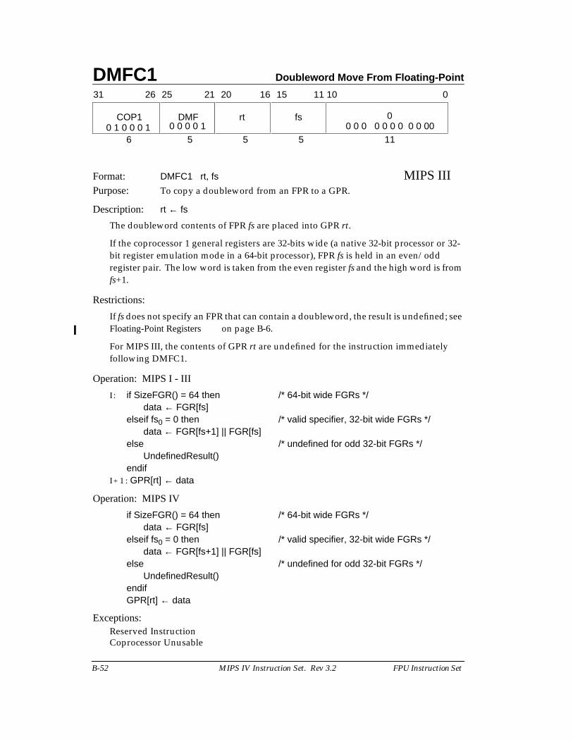
DMFC1 Doubleword Move From Floating-Point
B-52 MIPS IV Instruction Set. Rev 3.2 FPU Instruction Set
Format: DMFC1 rt, fs MIPS IIIPurpose: To copy a doubleword from an FPR to a GPR.
Description: rt ← fs
The doubleword contents of FPR fs are placed into GPR rt.
If the coprocessor 1 general registers are 32-bits wide (a native 32-bit processor or 32-bit register emulation mode in a 64-bit processor), FPR fs is held in an even/oddregister pair. The low word is taken from the even register fs and the high word is fromfs+1.
Restrictions:
If fs does not specify an FPR that can contain a doubleword, the result is undefined; seeFloating-Point Registers on page B-6.
For MIPS III, the contents of GPR rt are undefined for the instruction immediatelyfollowing DMFC1.
Operation: MIPS I - III
I : if SizeFGR() = 64 then /* 64-bit wide FGRs */data ← FGR[fs]
elseif fs0 = 0 then /* valid specifier, 32-bit wide FGRs */data ← FGR[fs+1] || FGR[fs]
else /* undefined for odd 32-bit FGRs */UndefinedResult()
endifI + 1 : GPR[rt] ← data
Operation: MIPS IV
if SizeFGR() = 64 then /* 64-bit wide FGRs */data ← FGR[fs]
elseif fs0 = 0 then /* valid specifier, 32-bit wide FGRs */data ← FGR[fs+1] || FGR[fs]
else /* undefined for odd 32-bit FGRs */UndefinedResult()
endifGPR[rt] ← data
Exceptions:Reserved InstructionCoprocessor Unusable
fs
11 10
5
31 2526 2021 1516 0
COP1 DMF rt 0
6 5 5 110 1 0 0 0 1 0 0 0 0 1 0 0 0 0 0 0 0 0 0 00
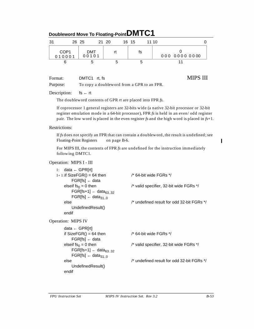
Doubleword Move To Floating-Point DMTC1
FPU Instruction Set MIPS IV Instruction Set. Rev 3.2 B-53
Format: DMTC1 rt, fs MIPS IIIPurpose: To copy a doubleword from a GPR to an FPR.
Description: fs ← rt
The doubleword contents of GPR rt are placed into FPR fs.
If coprocessor 1 general registers are 32-bits wide (a native 32-bit processor or 32-bitregister emulation mode in a 64-bit processor), FPR fs is held in an even/odd registerpair. The low word is placed in the even register fs and the high word is placed in fs+1.
Restrictions:
If fs does not specify an FPR that can contain a doubleword, the result is undefined; seeFloating-Point Registers on page B-6.
For MIPS III, the contents of FPR fs are undefined for the instruction immediatelyfollowing DMTC1.
Operation: MIPS I - III
I : data ← GPR[rt]I + 1 :if SizeFGR() = 64 then /* 64-bit wide FGRs */
FGR[fs] ← dataelseif fs0 = 0 then /* valid specifier, 32-bit wide FGRs */
FGR[fs+1] ← data63..32FGR[fs] ← data31..0
else /* undefined result for odd 32-bit FGRs */UndefinedResult()
endif
Operation: MIPS IV
data ← GPR[rt]if SizeFGR() = 64 then /* 64-bit wide FGRs */
FGR[fs] ← dataelseif fs0 = 0 then /* valid specifier, 32-bit wide FGRs */
FGR[fs+1] ← data63..32FGR[fs] ← data31..0
else /* undefined result for odd 32-bit FGRs */UndefinedResult()
endif
fs
11 10
5
31 2526 2021 1516 0
COP1 DMT rt 0
6 5 5 110 1 0 0 0 1 0 0 1 0 1 0 0 0 0 0 0 0 0 0 00
DMTC1 Doubleword Move To Floating-Point
B-54 MIPS IV Instruction Set. Rev 3.2 FPU Instruction Set
Exceptions:Reserved InstructionCoprocessor Unusable
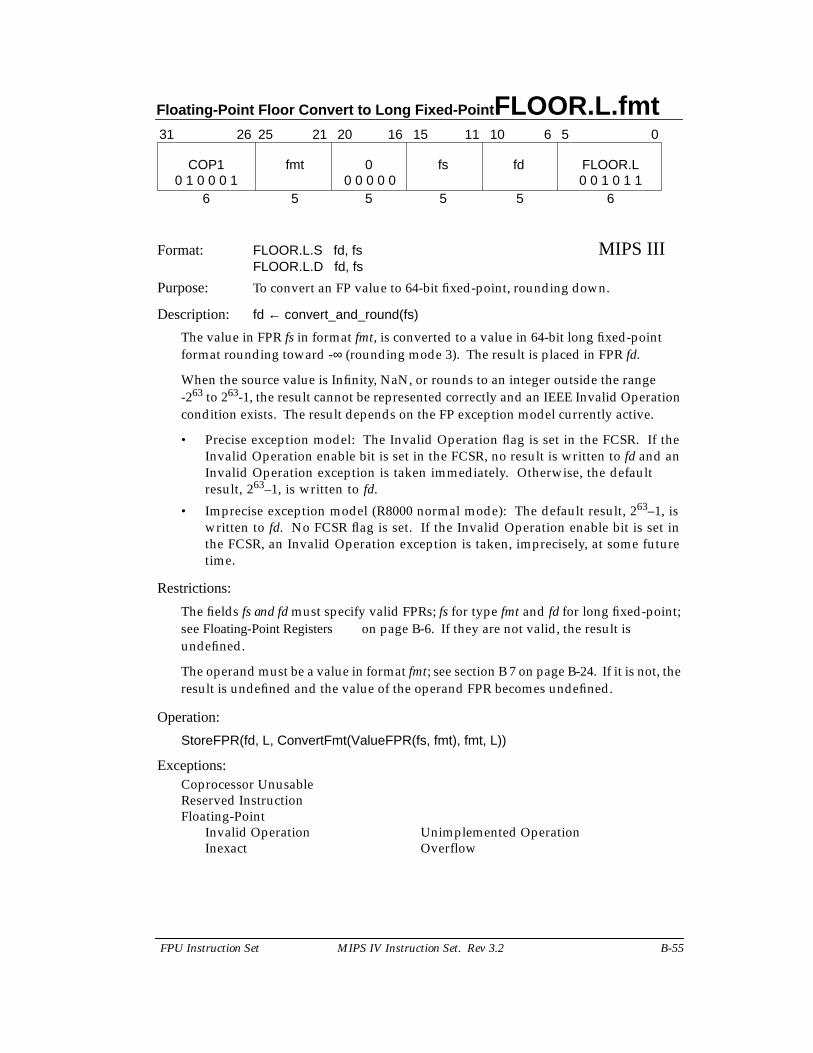
Floating-Point Floor Convert to Long Fixed-Point FLOOR.L.fmt
FPU Instruction Set MIPS IV Instruction Set. Rev 3.2 B-55
Format: FLOOR.L.S fd, fs MIPS IIIFLOOR.L.D fd, fs
Purpose: To convert an FP value to 64-bit fixed-point, rounding down.
Description: fd ← convert_and_round(fs)
The value in FPR fs in format fmt, is converted to a value in 64-bit long fixed-pointformat rounding toward -∞ (rounding mode 3). The result is placed in FPR fd.
When the source value is Infinity, NaN, or rounds to an integer outside the range-263 to 263-1, the result cannot be represented correctly and an IEEE Invalid Operationcondition exists. The result depends on the FP exception model currently active.
• Precise exception model: The Invalid Operation flag is set in the FCSR. If theInvalid Operation enable bit is set in the FCSR, no result is written to fd and anInvalid Operation exception is taken immediately. Otherwise, the defaultresult, 263–1, is written to fd.
• Imprecise exception model (R8000 normal mode): The default result, 263–1, iswritten to fd. No FCSR flag is set. If the Invalid Operation enable bit is set inthe FCSR, an Invalid Operation exception is taken, imprecisely, at some futuretime.
Restrictions:
The fields fs and fd must specify valid FPRs; fs for type fmt and fd for long fixed-point;see Floating-Point Registers on page B-6. If they are not valid, the result isundefined.
The operand must be a value in format fmt; see section B 7 on page B-24. If it is not, theresult is undefined and the value of the operand FPR becomes undefined.
Operation:
StoreFPR(fd, L, ConvertFmt(ValueFPR(fs, fmt), fmt, L))
Exceptions:Coprocessor UnusableReserved InstructionFloating-Point
Invalid Operation Unimplemented OperationInexact Overflow
31 0
6 5 5 5 5 6
COP1 fmt 0 fs fd FLOOR.L
11 1021 20 16 1526 25 6 5
0 1 0 0 0 1 0 0 0 0 0 0 0 1 0 1 1
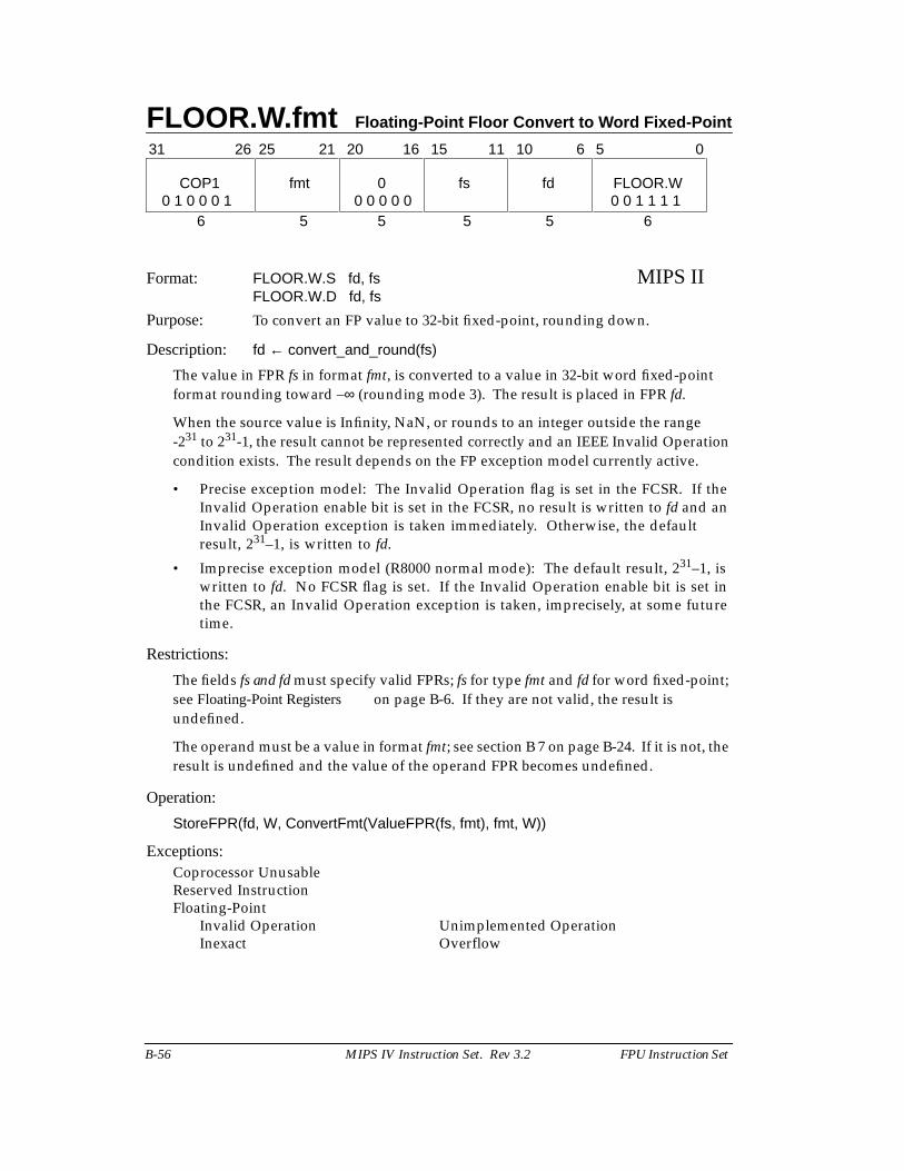
FLOOR.W.fmt Floating-Point Floor Convert to Word Fixed-Point
B-56 MIPS IV Instruction Set. Rev 3.2 FPU Instruction Set
Format: FLOOR.W.S fd, fs MIPS IIFLOOR.W.D fd, fs
Purpose: To convert an FP value to 32-bit fixed-point, rounding down.
Description: fd ← convert_and_round(fs)
The value in FPR fs in format fmt, is converted to a value in 32-bit word fixed-pointformat rounding toward –∞ (rounding mode 3). The result is placed in FPR fd.
When the source value is Infinity, NaN, or rounds to an integer outside the range-231 to 231-1, the result cannot be represented correctly and an IEEE Invalid Operationcondition exists. The result depends on the FP exception model currently active.
• Precise exception model: The Invalid Operation flag is set in the FCSR. If theInvalid Operation enable bit is set in the FCSR, no result is written to fd and anInvalid Operation exception is taken immediately. Otherwise, the defaultresult, 231–1, is written to fd.
• Imprecise exception model (R8000 normal mode): The default result, 231–1, iswritten to fd. No FCSR flag is set. If the Invalid Operation enable bit is set inthe FCSR, an Invalid Operation exception is taken, imprecisely, at some futuretime.
Restrictions:
The fields fs and fd must specify valid FPRs; fs for type fmt and fd for word fixed-point;see Floating-Point Registers on page B-6. If they are not valid, the result isundefined.
The operand must be a value in format fmt; see section B 7 on page B-24. If it is not, theresult is undefined and the value of the operand FPR becomes undefined.
Operation:
StoreFPR(fd, W, ConvertFmt(ValueFPR(fs, fmt), fmt, W))
Exceptions:Coprocessor UnusableReserved InstructionFloating-Point
Invalid Operation Unimplemented OperationInexact Overflow
31 0
6 5 5 5 5 6
COP1 fmt 0 fs fd FLOOR.W
11 1021 20 16 1526 25 6 5
0 1 0 0 0 1 0 0 1 1 1 10 0 0 0 0
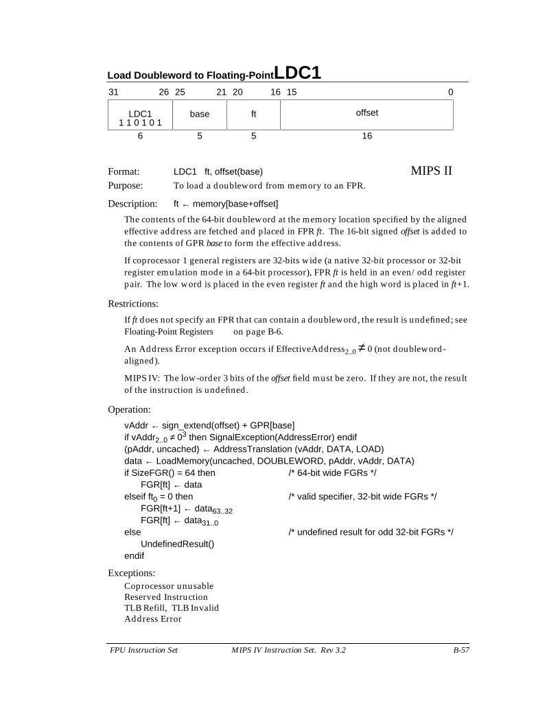
Load Doubleword to Floating-Point LDC1
FPU Instruction Set MIPS IV Instruction Set. Rev 3.2 B-57
Format: LDC1 ft, offset(base) MIPS IIPurpose: To load a doubleword from memory to an FPR.
Description: ft ← memory[base+offset]
The contents of the 64-bit doubleword at the memory location specified by the alignedeffective address are fetched and placed in FPR ft. The 16-bit signed offset is added tothe contents of GPR base to form the effective address.
If coprocessor 1 general registers are 32-bits wide (a native 32-bit processor or 32-bitregister emulation mode in a 64-bit processor), FPR ft is held in an even/odd registerpair. The low word is placed in the even register ft and the high word is placed in ft+1.
Restrictions:
If ft does not specify an FPR that can contain a doubleword, the result is undefined; seeFloating-Point Registers on page B-6.
An Address Error exception occurs if EffectiveAddress2..0 ≠ 0 (not doubleword-aligned).
MIPS IV: The low-order 3 bits of the offset field must be zero. If they are not, the resultof the instruction is undefined.
Operation:
vAddr ← sign_extend(offset) + GPR[base]if vAddr2..0 ≠ 03 then SignalException(AddressError) endif(pAddr, uncached) ← AddressTranslation (vAddr, DATA, LOAD)data ← LoadMemory(uncached, DOUBLEWORD, pAddr, vAddr, DATA)if SizeFGR() = 64 then /* 64-bit wide FGRs */
FGR[ft] ← dataelseif ft0 = 0 then /* valid specifier, 32-bit wide FGRs */
FGR[ft+1] ← data63..32FGR[ft] ← data31..0
else /* undefined result for odd 32-bit FGRs */UndefinedResult()
endif
Exceptions:Coprocessor unusableReserved InstructionTLB Refill, TLB InvalidAddress Error
31 2526 2021 1516 0
LDC1 base ft offset
6 5 5 161 1 0 1 0 1
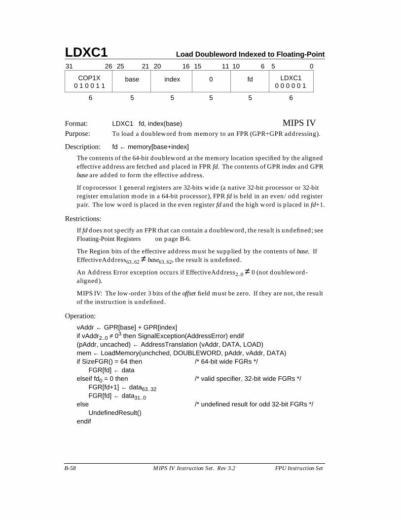
LDXC1 Load Doubleword Indexed to Floating-Point
B-58 MIPS IV Instruction Set. Rev 3.2 FPU Instruction Set
Format: LDXC1 fd, index(base) MIPS IVPurpose: To load a doubleword from memory to an FPR (GPR+GPR addressing).
Description: fd ← memory[base+index]
The contents of the 64-bit doubleword at the memory location specified by the alignedeffective address are fetched and placed in FPR fd. The contents of GPR index and GPRbase are added to form the effective address.
If coprocessor 1 general registers are 32-bits wide (a native 32-bit processor or 32-bitregister emulation mode in a 64-bit processor), FPR fd is held in an even/odd registerpair. The low word is placed in the even register fd and the high word is placed in fd+1.
Restrictions:
If fd does not specify an FPR that can contain a doubleword, the result is undefined; seeFloating-Point Registers on page B-6.
The Region bits of the effective address must be supplied by the contents of base. IfEffectiveAddress63..62 ≠ base63..62, the result is undefined.
An Address Error exception occurs if EffectiveAddress2..0 ≠ 0 (not doubleword-aligned).
MIPS IV: The low-order 3 bits of the offset field must be zero. If they are not, the resultof the instruction is undefined.
Operation:
vAddr ← GPR[base] + GPR[index]if vAddr2..0 ≠ 03 then SignalException(AddressError) endif(pAddr, uncached) ← AddressTranslation (vAddr, DATA, LOAD)mem ← LoadMemory(unchched, DOUBLEWORD, pAddr, vAddr, DATA)if SizeFGR() = 64 then /* 64-bit wide FGRs */
FGR[fd] ← dataelseif fd0 = 0 then /* valid specifier, 32-bit wide FGRs */
FGR[fd+1] ← data63..32FGR[fd] ← data31..0
else /* undefined result for odd 32-bit FGRs */UndefinedResult()
endif
31 2526 2021 1516
COP1X base index
6 5 5
0 fd LDXC1
5 5 6
11 10 6 5 0
0 0 0 0 0 10 1 0 0 1 1

Load Doubleword Indexed to Floating-Point LDXC1
FPU Instruction Set MIPS IV Instruction Set. Rev 3.2 B-59
Exceptions:TLB Refill, TLB InvalidAddress ErrorReserved InstructionCoprocessor Unusable
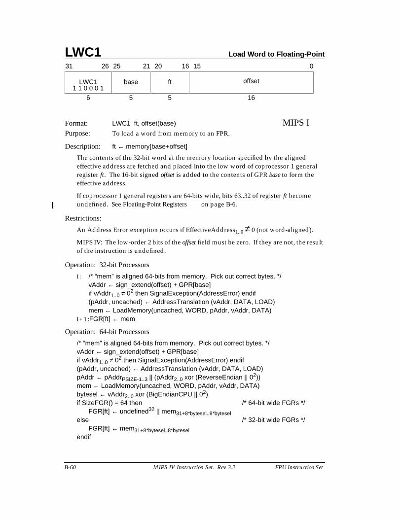
LWC1 Load Word to Floating-Point
B-60 MIPS IV Instruction Set. Rev 3.2 FPU Instruction Set
Format: LWC1 ft, offset(base) MIPS IPurpose: To load a word from memory to an FPR.
Description: ft ← memory[base+offset]
The contents of the 32-bit word at the memory location specified by the alignedeffective address are fetched and placed into the low word of coprocessor 1 generalregister ft. The 16-bit signed offset is added to the contents of GPR base to form theeffective address.
If coprocessor 1 general registers are 64-bits wide, bits 63..32 of register ft becomeundefined. See Floating-Point Registers on page B-6.
Restrictions:
An Address Error exception occurs if EffectiveAddress1..0 ≠ 0 (not word-aligned).
MIPS IV: The low-order 2 bits of the offset field must be zero. If they are not, the resultof the instruction is undefined.
Operation: 32-bit Processors
I : /* “mem” is aligned 64-bits from memory. Pick out correct bytes. */vAddr ← sign_extend(offset) + GPR[base]if vAddr1..0 ≠ 02 then SignalException(AddressError) endif(pAddr, uncached) ← AddressTranslation (vAddr, DATA, LOAD)mem ← LoadMemory(uncached, WORD, pAddr, vAddr, DATA)
I + 1 :FGR[ft] ← mem
Operation: 64-bit Processors
/* “mem” is aligned 64-bits from memory. Pick out correct bytes. */vAddr ← sign_extend(offset) + GPR[base]if vAddr1..0 ≠ 02 then SignalException(AddressError) endif(pAddr, uncached) ← AddressTranslation (vAddr, DATA, LOAD)pAddr ← pAddrPSIZE-1..3 || (pAddr2..0 xor (ReverseEndian || 02))mem ← LoadMemory(uncached, WORD, pAddr, vAddr, DATA)bytesel ← vAddr2..0 xor (BigEndianCPU || 02)if SizeFGR() = 64 then /* 64-bit wide FGRs */
FGR[ft] ← undefined32 || mem31+8*bytesel..8*byteselelse /* 32-bit wide FGRs */
FGR[ft] ← mem31+8*bytesel..8*byteselendif
LWC1
61 1 0 0 0 1
31 2526 2021 1516 0
base ft offset
5 5 16

Load Word to Floating-Point LWC1
FPU Instruction Set MIPS IV Instruction Set. Rev 3.2 B-61
Exceptions:Coprocessor unusableReserved InstructionTLB Refill, TLB InvalidAddress Error
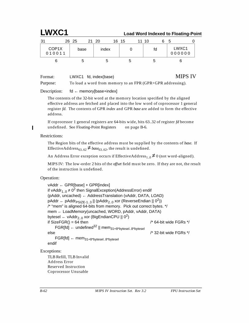
LWXC1 Load Word Indexed to Floating-Point
B-62 MIPS IV Instruction Set. Rev 3.2 FPU Instruction Set
Format: LWXC1 fd, index(base) MIPS IVPurpose: To load a word from memory to an FPR (GPR+GPR addressing).
Description: fd ← memory[base+index]
The contents of the 32-bit word at the memory location specified by the alignedeffective address are fetched and placed into the low word of coprocessor 1 generalregister fd. The contents of GPR index and GPR base are added to form the effectiveaddress.
If coprocessor 1 general registers are 64-bits wide, bits 63..32 of register fd becomeundefined. See Floating-Point Registers on page B-6.
Restrictions:
The Region bits of the effective address must be supplied by the contents of base. IfEffectiveAddress63..62 ≠ base63..62, the result is undefined.
An Address Error exception occurs if EffectiveAddress1..0 ≠ 0 (not word-aligned).
MIPS IV: The low-order 2 bits of the offset field must be zero. If they are not, the resultof the instruction is undefined.
Operation:
vAddr ← GPR[base] + GPR[index]if vAddr1..0 ≠ 02 then SignalException(AddressError) endif(pAddr, uncached) ← AddressTranslation (vAddr, DATA, LOAD)pAddr ← pAddrPSIZE-1..3 || (pAddr2..0 xor (ReverseEndian || 02))/* “mem” is aligned 64-bits from memory. Pick out correct bytes. */mem ← LoadMemory(uncached, WORD, pAddr, vAddr, DATA)bytesel ← vAddr2..0 xor (BigEndianCPU || 02)if SizeFGR() = 64 then /* 64-bit wide FGRs */
FGR[fd] ← undefined32 || mem31+8*bytesel..8*byteselelse /* 32-bit wide FGRs */
FGR[fd] ← mem31+8*bytesel..8*byteselendif
Exceptions:TLB Refill, TLB InvalidAddress ErrorReserved InstructionCoprocessor Unusable
31 2526 2021 1516
COP1X base index
6 5 5
0 fd LWXC1
5 5 6
11 10 6 5 0
0 0 0 0 0 00 1 0 0 1 1
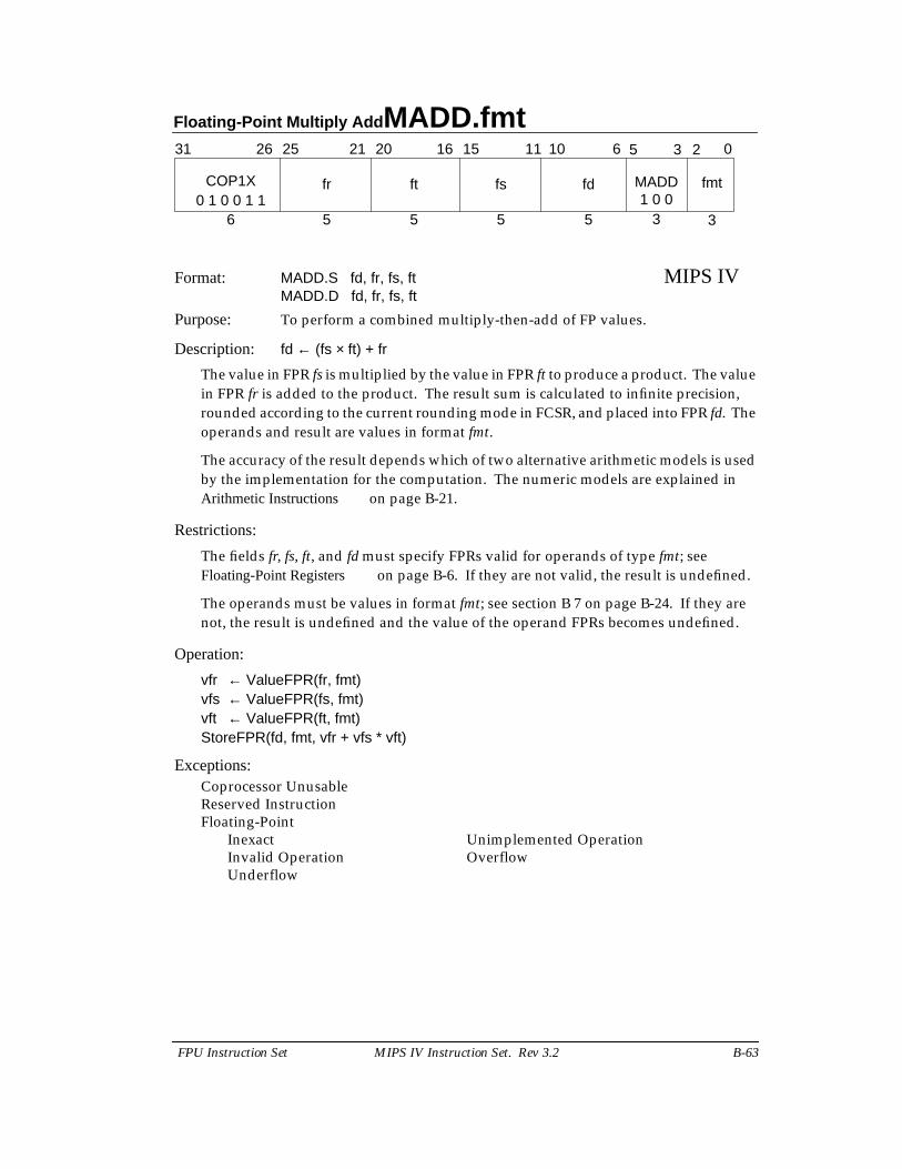
Floating-Point Multiply Add MADD.fmt
FPU Instruction Set MIPS IV Instruction Set. Rev 3.2 B-63
Format: MADD.S fd, fr, fs, ft MIPS IVMADD.D fd, fr, fs, ft
Purpose: To perform a combined multiply-then-add of FP values.
Description: fd ← (fs × ft) + fr
The value in FPR fs is multiplied by the value in FPR ft to produce a product. The valuein FPR fr is added to the product. The result sum is calculated to infinite precision,rounded according to the current rounding mode in FCSR, and placed into FPR fd. Theoperands and result are values in format fmt.
The accuracy of the result depends which of two alternative arithmetic models is usedby the implementation for the computation. The numeric models are explained inArithmetic Instructions on page B-21.
Restrictions:
The fields fr, fs, ft, and fd must specify FPRs valid for operands of type fmt; seeFloating-Point Registers on page B-6. If they are not valid, the result is undefined.
The operands must be values in format fmt; see section B 7 on page B-24. If they arenot, the result is undefined and the value of the operand FPRs becomes undefined.
Operation:
vfr ← ValueFPR(fr, fmt)vfs ← ValueFPR(fs, fmt)vft ← ValueFPR(ft, fmt)StoreFPR(fd, fmt, vfr + vfs * vft)
Exceptions:Coprocessor UnusableReserved InstructionFloating-Point
Inexact Unimplemented OperationInvalid Operation OverflowUnderflow
31 2526 2021 1516
COP1X fr ft
6 5 5
fs fd
5 5 3
11 10 6 5 0
3
fmt0 1 0 0 1 1
MADD
3 2
1 0 0
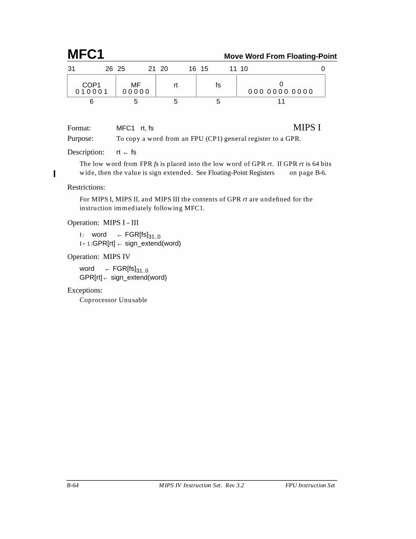
MFC1 Move Word From Floating-Point
B-64 MIPS IV Instruction Set. Rev 3.2 FPU Instruction Set
Format: MFC1 rt, fs MIPS IPurpose: To copy a word from an FPU (CP1) general register to a GPR.
Description: rt ← fs
The low word from FPR fs is placed into the low word of GPR rt. If GPR rt is 64 bitswide, then the value is sign extended. See Floating-Point Registers on page B-6.
Restrictions:
For MIPS I, MIPS II, and MIPS III the contents of GPR rt are undefined for theinstruction immediately following MFC1.
Operation: MIPS I - III
I : word ← FGR[fs]31..0I + 1 :GPR[rt] ← sign_extend(word)
Operation: MIPS IV
word ← FGR[fs]31..0GPR[rt]← sign_extend(word)
Exceptions:Coprocessor Unusable
11
31 2526 2021 1516
COP1 MF rt
6 5 5
fs 0
5
11 10 0
0 1 0 0 0 1 0 0 0 0 0 0 0 0 0 0 0 0 0 0 0 0
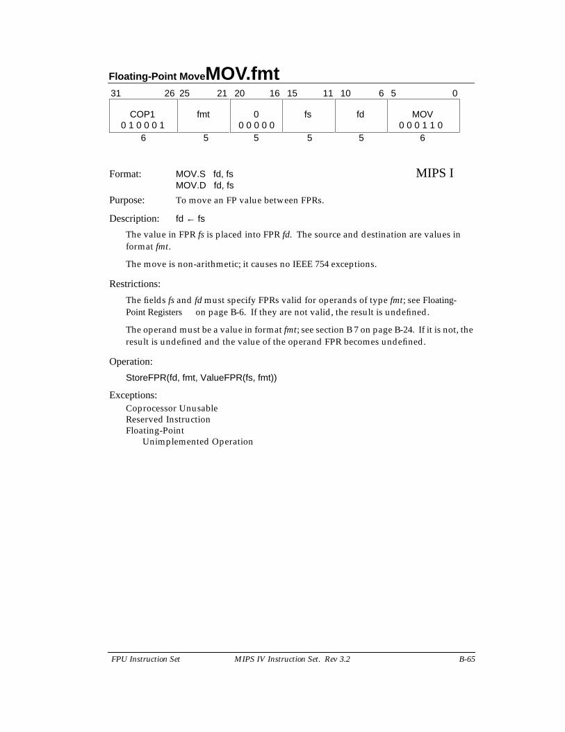
Floating-Point Move MOV.fmt
FPU Instruction Set MIPS IV Instruction Set. Rev 3.2 B-65
Format: MOV.S fd, fs MIPS IMOV.D fd, fs
Purpose: To move an FP value between FPRs.
Description: fd ← fs
The value in FPR fs is placed into FPR fd. The source and destination are values informat fmt.
The move is non-arithmetic; it causes no IEEE 754 exceptions.
Restrictions:
The fields fs and fd must specify FPRs valid for operands of type fmt; see Floating-Point Registers on page B-6. If they are not valid, the result is undefined.
The operand must be a value in format fmt; see section B 7 on page B-24. If it is not, theresult is undefined and the value of the operand FPR becomes undefined.
Operation:
StoreFPR(fd, fmt, ValueFPR(fs, fmt))
Exceptions:Coprocessor UnusableReserved InstructionFloating-Point
Unimplemented Operation
31 0
6 5 5 5 5 6
COP1 fmt 0 fs fd MOV
11 1021 20 16 1526 25 6 5
0 1 0 0 0 1 0 0 0 1 1 00 0 0 0 0
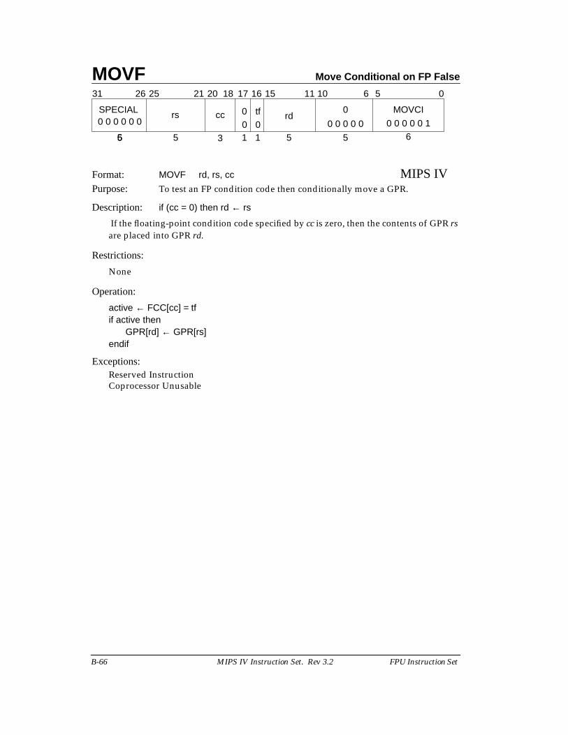
MOVF Move Conditional on FP False
B-66 MIPS IV Instruction Set. Rev 3.2 FPU Instruction Set
Format: MOVF rd, rs, cc MIPS IVPurpose: To test an FP condition code then conditionally move a GPR.
Description: if (cc = 0) then rd ← rs
If the floating-point condition code specified by cc is zero, then the contents of GPR rsare placed into GPR rd.
Restrictions:
None
Operation:
active ← FCC[cc] = tfif active then
GPR[rd] ← GPR[rs]endif
Exceptions:Reserved InstructionCoprocessor Unusable
31 2526 1516 0
6 35
6 5
6
SPECIAL
5
11 1021 20 18 17
5 1 1
0 MOVCItf0ccrs00 0 0 0 0 0 0 0 0 0 0 10 0 0 0 00
rd
5
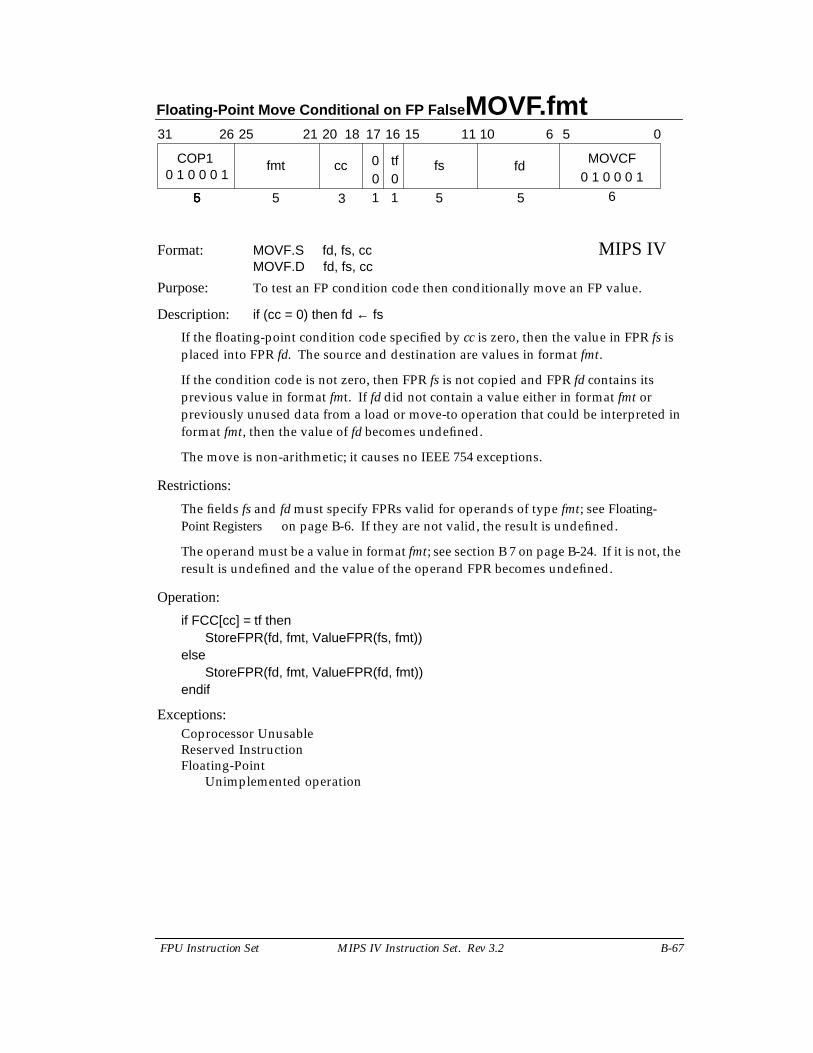
Floating-Point Move Conditional on FP False MOVF.fmt
FPU Instruction Set MIPS IV Instruction Set. Rev 3.2 B-67
Format: MOVF.S fd, fs, cc MIPS IVMOVF.D fd, fs, cc
Purpose: To test an FP condition code then conditionally move an FP value.
Description: if (cc = 0) then fd ← fs
If the floating-point condition code specified by cc is zero, then the value in FPR fs isplaced into FPR fd. The source and destination are values in format fmt.
If the condition code is not zero, then FPR fs is not copied and FPR fd contains itsprevious value in format fmt. If fd did not contain a value either in format fmt orpreviously unused data from a load or move-to operation that could be interpreted informat fmt, then the value of fd becomes undefined.
The move is non-arithmetic; it causes no IEEE 754 exceptions.
Restrictions:
The fields fs and fd must specify FPRs valid for operands of type fmt; see Floating-Point Registers on page B-6. If they are not valid, the result is undefined.
The operand must be a value in format fmt; see section B 7 on page B-24. If it is not, theresult is undefined and the value of the operand FPR becomes undefined.
Operation:
if FCC[cc] = tf thenStoreFPR(fd, fmt, ValueFPR(fs, fmt))
elseStoreFPR(fd, fmt, ValueFPR(fd, fmt))
endif
Exceptions:Coprocessor UnusableReserved InstructionFloating-Point
Unimplemented operation
31 2526 1516 0
6 35
6 5
6
COP1
5
11 1021 20 18 17
5 1 1
fd MOVCFtf0ccfmt00 1 0 0 0 1 0 1 0 0 0 10
fs
55
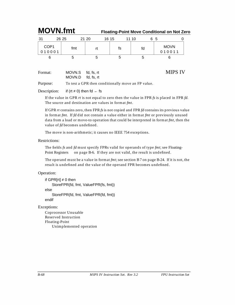
MOVN.fmt Floating-Point Move Conditional on Not Zero
B-68 MIPS IV Instruction Set. Rev 3.2 FPU Instruction Set
Format: MOVN.S fd, fs, rt MIPS IVMOVN.D fd, fs, rt
Purpose: To test a GPR then conditionally move an FP value.
Description: if (rt ≠ 0) then fd ← fs
If the value in GPR rt is not equal to zero then the value in FPR fs is placed in FPR fd.The source and destination are values in format fmt.
If GPR rt contains zero, then FPR fs is not copied and FPR fd contains its previous valuein format fmt. If fd did not contain a value either in format fmt or previously unuseddata from a load or move-to operation that could be interpreted in format fmt, then thevalue of fd becomes undefined.
The move is non-arithmetic; it causes no IEEE 754 exceptions.
Restrictions:
The fields fs and fd must specify FPRs valid for operands of type fmt; see Floating-Point Registers on page B-6. If they are not valid, the result is undefined.
The operand must be a value in format fmt; see section B 7 on page B-24. If it is not, theresult is undefined and the value of the operand FPR becomes undefined.
Operation:
if GPR[rt] ≠ 0 thenStoreFPR(fd, fmt, ValueFPR(fs, fmt))
elseStoreFPR(fd, fmt, ValueFPR(fd, fmt))
endif
Exceptions:Coprocessor UnusableReserved InstructionFloating-Point
Unimplemented operation
31 2526 1516 0
6 5 5
6 5
6
COP1
5
11 1021 20
5
fd MOVNfsrtfmt0 1 0 0 0 1 0 1 0 0 1 1

Move Conditional on FP True MOVT
FPU Instruction Set MIPS IV Instruction Set. Rev 3.2 B-69
Format: MOVT rd, rs, cc MIPS IVPurpose: To test an FP condition code then conditionally move a GPR.
Description: if (cc = 1) then rd ← rs
If the floating-point condition code specified by cc is one then the contents of GPR rsare placed into GPR rd.
Restrictions:
None
Operation:
if FCC[cc] = tf thenGPR[rd] ← GPR[rs]
endif
Exceptions:Reserved InstructionCoprocessor Unusable
31 2526 1516 0
6 3 5
6 5
6
SPECIAL
5
11 1021 20 18 17
5 1 1
0 MOVCIrdtf0ccrs10 0 0 0 0 0 0 0 0 0 0 10 0 0 0 0 0
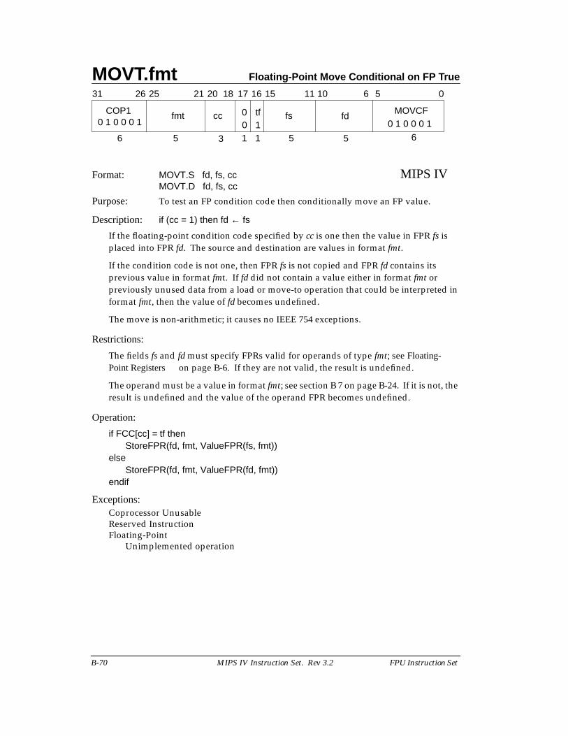
MOVT.fmt Floating-Point Move Conditional on FP True
B-70 MIPS IV Instruction Set. Rev 3.2 FPU Instruction Set
Format: MOVT.S fd, fs, cc MIPS IVMOVT.D fd, fs, cc
Purpose: To test an FP condition code then conditionally move an FP value.
Description: if (cc = 1) then fd ← fs
If the floating-point condition code specified by cc is one then the value in FPR fs isplaced into FPR fd. The source and destination are values in format fmt.
If the condition code is not one, then FPR fs is not copied and FPR fd contains itsprevious value in format fmt. If fd did not contain a value either in format fmt orpreviously unused data from a load or move-to operation that could be interpreted informat fmt, then the value of fd becomes undefined.
The move is non-arithmetic; it causes no IEEE 754 exceptions.
Restrictions:
The fields fs and fd must specify FPRs valid for operands of type fmt; see Floating-Point Registers on page B-6. If they are not valid, the result is undefined.
The operand must be a value in format fmt; see section B 7 on page B-24. If it is not, theresult is undefined and the value of the operand FPR becomes undefined.
Operation:
if FCC[cc] = tf thenStoreFPR(fd, fmt, ValueFPR(fs, fmt))
elseStoreFPR(fd, fmt, ValueFPR(fd, fmt))
endif
Exceptions:Coprocessor UnusableReserved InstructionFloating-Point
Unimplemented operation
31 2526 1516 0
6 3 5
6 5
6
COP1
5
11 1021 20 18 17
5 1 1
fd MOVCFfstf0ccfmt10 1 0 0 0 1 0 1 0 0 0 10
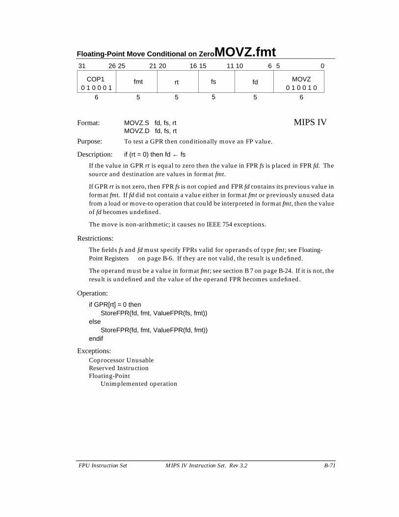
Floating-Point Move Conditional on Zero MOVZ.fmt
FPU Instruction Set MIPS IV Instruction Set. Rev 3.2 B-71
Format: MOVZ.S fd, fs, rt MIPS IVMOVZ.D fd, fs, rt
Purpose: To test a GPR then conditionally move an FP value.
Description: if (rt = 0) then fd ← fs
If the value in GPR rt is equal to zero then the value in FPR fs is placed in FPR fd. Thesource and destination are values in format fmt.
If GPR rt is not zero, then FPR fs is not copied and FPR fd contains its previous value informat fmt. If fd did not contain a value either in format fmt or previously unused datafrom a load or move-to operation that could be interpreted in format fmt, then the valueof fd becomes undefined.
The move is non-arithmetic; it causes no IEEE 754 exceptions.
Restrictions:
The fields fs and fd must specify FPRs valid for operands of type fmt; see Floating-Point Registers on page B-6. If they are not valid, the result is undefined.
The operand must be a value in format fmt; see section B 7 on page B-24. If it is not, theresult is undefined and the value of the operand FPR becomes undefined.
Operation:
if GPR[rt] = 0 thenStoreFPR(fd, fmt, ValueFPR(fs, fmt))
elseStoreFPR(fd, fmt, ValueFPR(fd, fmt))
endif
Exceptions:Coprocessor UnusableReserved InstructionFloating-Point
Unimplemented operation
31 2526 1516 0
6 5 5
6 5
6
COP1
5
11 1021 20
5
fd MOVZfsrtfmt0 1 0 0 0 1 0 1 0 0 1 0
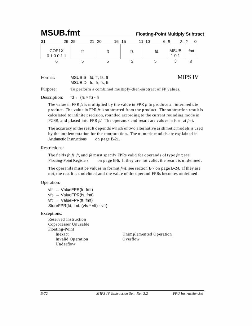
MSUB.fmt Floating-Point Multiply Subtract
B-72 MIPS IV Instruction Set. Rev 3.2 FPU Instruction Set
Format: MSUB.S fd, fr, fs, ft MIPS IVMSUB.D fd, fr, fs, ft
Purpose: To perform a combined multiply-then-subtract of FP values.
Description: fd ← (fs × ft) - fr
The value in FPR fs is multiplied by the value in FPR ft to produce an intermediateproduct. The value in FPR fr is subtracted from the product. The subtraction result iscalculated to infinite precision, rounded according to the current rounding mode inFCSR, and placed into FPR fd. The operands and result are values in format fmt.
The accuracy of the result depends which of two alternative arithmetic models is usedby the implementation for the computation. The numeric models are explained inArithmetic Instructions on page B-21.
Restrictions:
The fields fr, fs, ft, and fd must specify FPRs valid for operands of type fmt; seeFloating-Point Registers on page B-6. If they are not valid, the result is undefined.
The operands must be values in format fmt; see section B 7 on page B-24. If they arenot, the result is undefined and the value of the operand FPRs becomes undefined.
Operation:
vfr ← ValueFPR(fr, fmt)vfs ← ValueFPR(fs, fmt)vft ← ValueFPR(ft, fmt)StoreFPR(fd, fmt, (vfs * vft) - vfr)
Exceptions:Reserved InstructionCoprocessor UnusableFloating-Point
Inexact Unimplemented OperationInvalid Operation OverflowUnderflow
31 2526 2021 1516
COP1X fr ft
6 5 5
fs fd
5 5 3
11 10 6 5 0
3
fmt0 1 0 0 1 1
MSUB
3 2
1 0 1
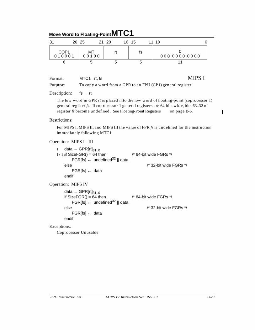
Move Word to Floating-Point MTC1
FPU Instruction Set MIPS IV Instruction Set. Rev 3.2 B-73
Format: MTC1 rt, fs MIPS IPurpose: To copy a word from a GPR to an FPU (CP1) general register.
Description: fs ← rt
The low word in GPR rt is placed into the low word of floating-point (coprocessor 1)general register fs. If coprocessor 1 general registers are 64-bits wide, bits 63..32 ofregister fs become undefined. See Floating-Point Registers on page B-6.
Restrictions:
For MIPS I, MIPS II, and MIPS III the value of FPR fs is undefined for the instructionimmediately following MTC1.
Operation: MIPS I - III
I : data ← GPR[rt]31..0I + 1 :if SizeFGR() = 64 then /* 64-bit wide FGRs */
FGR[fs] ← undefined32 || dataelse /* 32-bit wide FGRs */
FGR[fs] ← dataendif
Operation: MIPS IV
data ← GPR[rt]31..0if SizeFGR() = 64 then /* 64-bit wide FGRs */
FGR[fs] ← undefined32 || dataelse /* 32-bit wide FGRs */
FGR[fs] ← dataendif
Exceptions:Coprocessor Unusable
11
31 2526 2021 1516
COP1 MT rt
6 5 5
fs 0
5
11 10 0
0 1 0 0 0 1 0 0 0 0 0 0 0 0 0 0 00 0 1 0 0
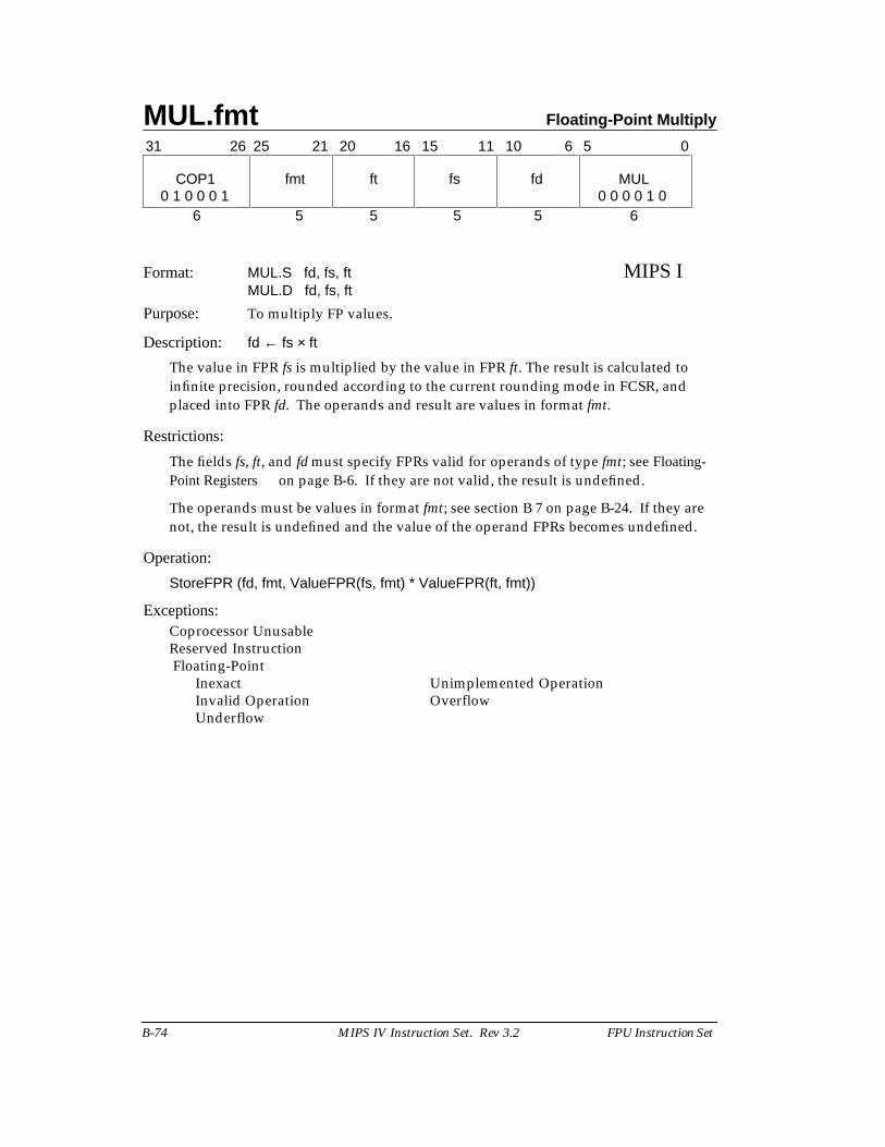
MUL.fmt Floating-Point Multiply
B-74 MIPS IV Instruction Set. Rev 3.2 FPU Instruction Set
Format: MUL.S fd, fs, ft MIPS IMUL.D fd, fs, ft
Purpose: To multiply FP values.
Description: fd ← fs × ft
The value in FPR fs is multiplied by the value in FPR ft. The result is calculated toinfinite precision, rounded according to the current rounding mode in FCSR, andplaced into FPR fd. The operands and result are values in format fmt.
Restrictions:
The fields fs, ft, and fd must specify FPRs valid for operands of type fmt; see Floating-Point Registers on page B-6. If they are not valid, the result is undefined.
The operands must be values in format fmt; see section B 7 on page B-24. If they arenot, the result is undefined and the value of the operand FPRs becomes undefined.
Operation:
StoreFPR (fd, fmt, ValueFPR(fs, fmt) * ValueFPR(ft, fmt))
Exceptions:Coprocessor UnusableReserved Instruction Floating-Point
Inexact Unimplemented OperationInvalid Operation OverflowUnderflow
31 0
6 5 5 5 5 6
COP1 fmt ft fs fd MUL
11 1021 20 16 1526 25 6 5
0 1 0 0 0 1 0 0 0 0 1 0
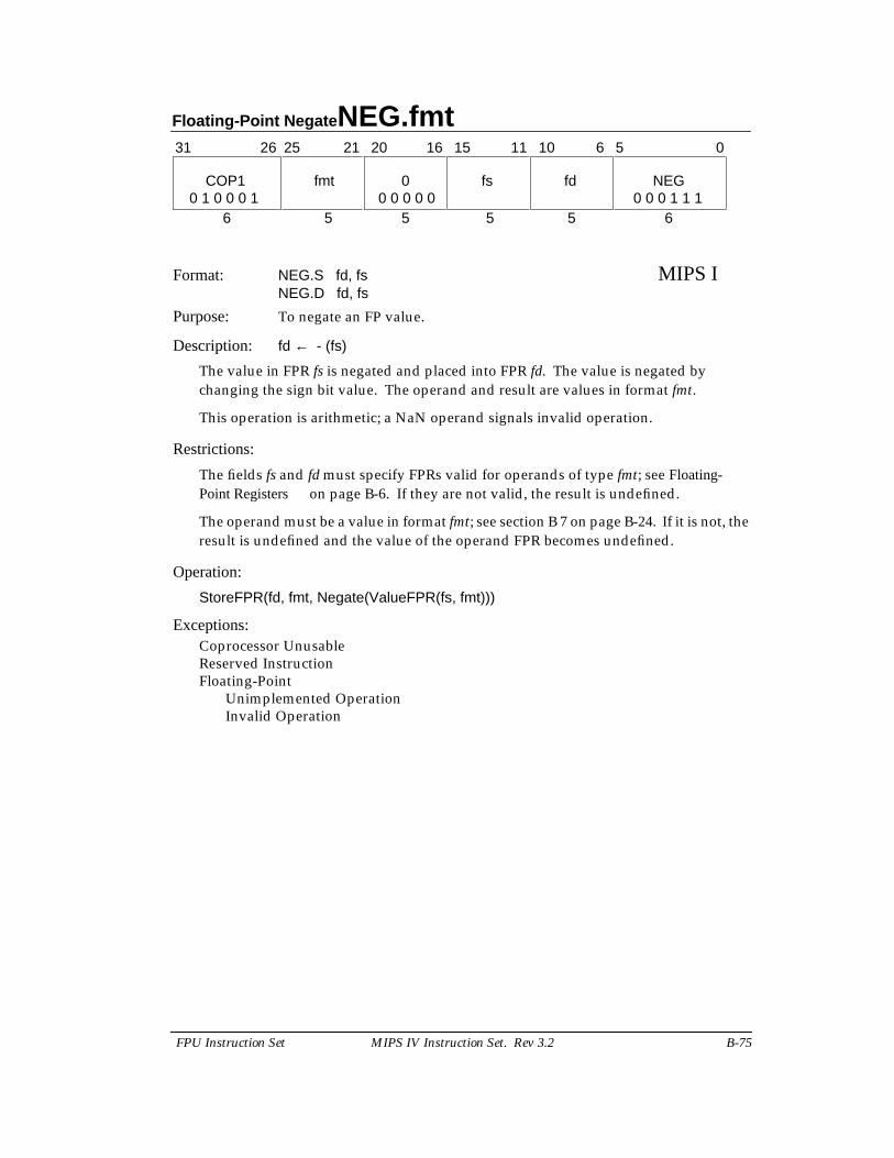
Floating-Point Negate NEG.fmt
FPU Instruction Set MIPS IV Instruction Set. Rev 3.2 B-75
Format: NEG.S fd, fs MIPS INEG.D fd, fs
Purpose: To negate an FP value.
Description: fd ← - (fs)
The value in FPR fs is negated and placed into FPR fd. The value is negated bychanging the sign bit value. The operand and result are values in format fmt.
This operation is arithmetic; a NaN operand signals invalid operation.
Restrictions:
The fields fs and fd must specify FPRs valid for operands of type fmt; see Floating-Point Registers on page B-6. If they are not valid, the result is undefined.
The operand must be a value in format fmt; see section B 7 on page B-24. If it is not, theresult is undefined and the value of the operand FPR becomes undefined.
Operation:
StoreFPR(fd, fmt, Negate(ValueFPR(fs, fmt)))
Exceptions:Coprocessor UnusableReserved InstructionFloating-Point
Unimplemented OperationInvalid Operation
31 0
6 5 5 5 5 6
COP1 fmt 0 fs fd NEG
11 1021 20 16 1526 25 6 5
0 1 0 0 0 1 0 0 0 1 1 10 0 0 0 0
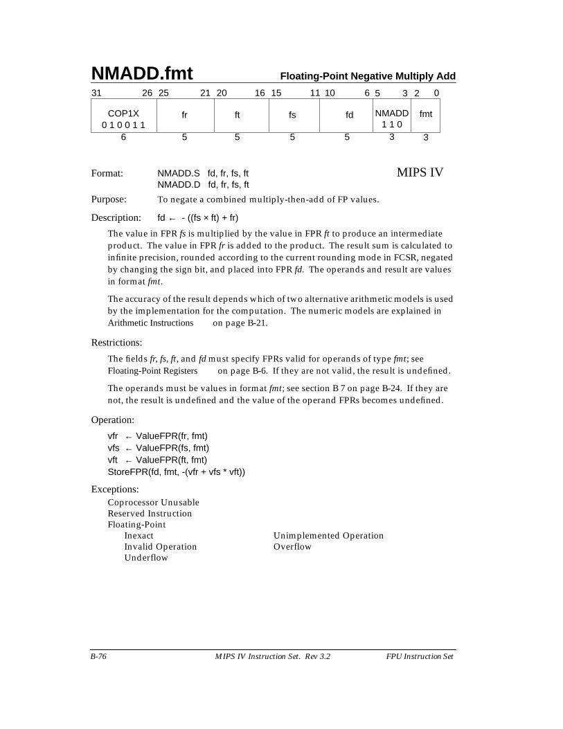
NMADD.fmt Floating-Point Negative Multiply Add
B-76 MIPS IV Instruction Set. Rev 3.2 FPU Instruction Set
Format: NMADD.S fd, fr, fs, ft MIPS IVNMADD.D fd, fr, fs, ft
Purpose: To negate a combined multiply-then-add of FP values.
Description: fd ← - ((fs × ft) + fr)
The value in FPR fs is multiplied by the value in FPR ft to produce an intermediateproduct. The value in FPR fr is added to the product. The result sum is calculated toinfinite precision, rounded according to the current rounding mode in FCSR, negatedby changing the sign bit, and placed into FPR fd. The operands and result are valuesin format fmt.
The accuracy of the result depends which of two alternative arithmetic models is usedby the implementation for the computation. The numeric models are explained inArithmetic Instructions on page B-21.
Restrictions:
The fields fr, fs, ft, and fd must specify FPRs valid for operands of type fmt; seeFloating-Point Registers on page B-6. If they are not valid, the result is undefined.
The operands must be values in format fmt; see section B 7 on page B-24. If they arenot, the result is undefined and the value of the operand FPRs becomes undefined.
Operation:
vfr ← ValueFPR(fr, fmt)vfs ← ValueFPR(fs, fmt)vft ← ValueFPR(ft, fmt)StoreFPR(fd, fmt, -(vfr + vfs * vft))
Exceptions:Coprocessor UnusableReserved InstructionFloating-Point
Inexact Unimplemented OperationInvalid Operation OverflowUnderflow
31 2526 2021 1516
COP1X fr ft
6 5 5
fs fd
5 5 3
11 10 6 5 0
3
fmt0 1 0 0 1 1
NMADD
3 2
1 1 0
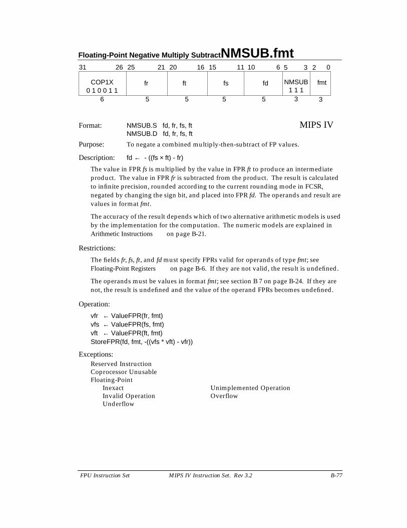
Floating-Point Negative Multiply Subtract NMSUB.fmt
FPU Instruction Set MIPS IV Instruction Set. Rev 3.2 B-77
Format: NMSUB.S fd, fr, fs, ft MIPS IVNMSUB.D fd, fr, fs, ft
Purpose: To negate a combined multiply-then-subtract of FP values.
Description: fd ← - ((fs × ft) - fr)
The value in FPR fs is multiplied by the value in FPR ft to produce an intermediateproduct. The value in FPR fr is subtracted from the product. The result is calculatedto infinite precision, rounded according to the current rounding mode in FCSR,negated by changing the sign bit, and placed into FPR fd. The operands and result arevalues in format fmt.
The accuracy of the result depends which of two alternative arithmetic models is usedby the implementation for the computation. The numeric models are explained inArithmetic Instructions on page B-21.
Restrictions:
The fields fr, fs, ft, and fd must specify FPRs valid for operands of type fmt; seeFloating-Point Registers on page B-6. If they are not valid, the result is undefined.
The operands must be values in format fmt; see section B 7 on page B-24. If they arenot, the result is undefined and the value of the operand FPRs becomes undefined.
Operation:
vfr ← ValueFPR(fr, fmt)vfs ← ValueFPR(fs, fmt)vft ← ValueFPR(ft, fmt)StoreFPR(fd, fmt, -((vfs * vft) - vfr))
Exceptions:Reserved InstructionCoprocessor UnusableFloating-Point
Inexact Unimplemented OperationInvalid Operation OverflowUnderflow
31 2526 2021 1516
COP1X fr ft
6 5 5
fs fd
5 5 3
11 10 6 5 0
3
fmt0 1 0 0 1 1
NMSUB
3 2
1 1 1
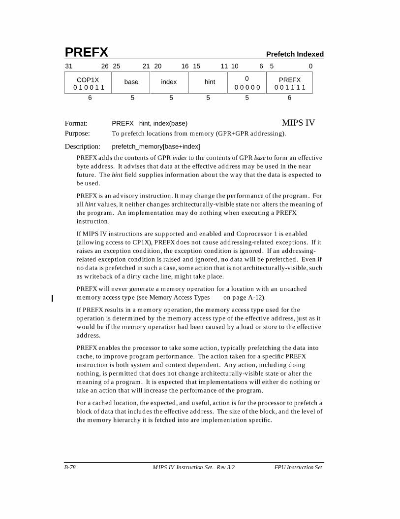
PREFX Prefetch Indexed
B-78 MIPS IV Instruction Set. Rev 3.2 FPU Instruction Set
Format: PREFX hint, index(base) MIPS IVPurpose: To prefetch locations from memory (GPR+GPR addressing).
Description: prefetch_memory[base+index]
PREFX adds the contents of GPR index to the contents of GPR base to form an effectivebyte address. It advises that data at the effective address may be used in the nearfuture. The hint field supplies information about the way that the data is expected tobe used.
PREFX is an advisory instruction. It may change the performance of the program. Forall hint values, it neither changes architecturally-visible state nor alters the meaning ofthe program. An implementation may do nothing when executing a PREFXinstruction.
If MIPS IV instructions are supported and enabled and Coprocessor 1 is enabled(allowing access to CP1X), PREFX does not cause addressing-related exceptions. If itraises an exception condition, the exception condition is ignored. If an addressing-related exception condition is raised and ignored, no data will be prefetched. Even ifno data is prefetched in such a case, some action that is not architecturally-visible, suchas writeback of a dirty cache line, might take place.
PREFX will never generate a memory operation for a location with an uncachedmemory access type (see Memory Access Types on page A-12).
If PREFX results in a memory operation, the memory access type used for theoperation is determined by the memory access type of the effective address, just as itwould be if the memory operation had been caused by a load or store to the effectiveaddress.
PREFX enables the processor to take some action, typically prefetching the data intocache, to improve program performance. The action taken for a specific PREFXinstruction is both system and context dependent. Any action, including doingnothing, is permitted that does not change architecturally-visible state or alter themeaning of a program. It is expected that implementations will either do nothing ortake an action that will increase the performance of the program.
For a cached location, the expected, and useful, action is for the processor to prefetch ablock of data that includes the effective address. The size of the block, and the level ofthe memory hierarchy it is fetched into are implementation specific.
31 2526 2021 1516
COP1X base index
6 5 5
hint 0 PREFX
5 5 6
11 10 6 5 0
0 1 0 0 1 1 0 0 0 0 0 0 0 1 1 1 1

Prefetch Indexed PREFX
FPU Instruction Set MIPS IV Instruction Set. Rev 3.2 B-79
The hint field supplies information about the way the data is expected to be used. Nohint value causes an action that modifies architecturally-visible state. A processor mayuse a hint value to improve the effectiveness of the prefetch action. The defined hintvalues and the recommended prefetch action are shown in the table below. The hinttable may be extended in future implementations.
Restrictions:
The Region bits of the effective address must be supplied by the contents of base. IfEffectiveAddress63..62 ≠ base63..62, the result of the instruction is undefined.
Operation:
vAddr ← GPR[base] + GPR[index](pAddr, uncached) ← AddressTranslation(vAddr, DATA, LOAD)Prefetch(uncached, pAddr, vAddr, DATA, hint)
Table B-22 Values of Hint Field for Prefetch Instruction
Value Name Data use and desired prefetch action
0 load Data is expected to be loaded (not modified).Fetch data as if for a load.
1 store Data is expected to be stored or modified.Fetch data as if for a store.
2-3 Not yet defined.
4 load_streamed Data is expected to be loaded (not modified) but notreused extensively; it will “stream” through cache.Fetch data as if for a load and place it in the cache sothat it will not displace data prefetched as “retained”.
5 store_streamed Data is expected to be stored or modified but notreused extensively; it will “stream” through cache.Fetch data as if for a store and place it in the cache sothat it will not displace data prefetched as “retained”.
6 load_retained Data is expected to be loaded (not modified) andreused extensively; it should be “retained” in the cache.Fetch data as if for a load and place it in the cache sothat it will not be displaced by data prefetched as“streamed”.
7 store_retained Data is expected to be stored or modified and reusedextensively; it should be “retained” in the cache.Fetch data as if for a store and place it in the cache sothat will not be displaced by data prefetched as“streamed”.
8-31 Not yet defined.
PREFX Prefetch Indexed
B-80 MIPS IV Instruction Set. Rev 3.2 FPU Instruction Set
Exceptions:Reserved InstructionCoprocessor Unusable
Programming Notes:
Prefetch can not prefetch data from a mapped location unless the translation for thatlocation is present in the TLB. Locations in memory pages that have not been accessedrecently may not have translations in the TLB, so prefetch may not be effective for suchlocations.
Prefetch does not cause addressing exceptions. It will not cause an exception toprefetch using an address pointer value before the validity of a pointer is determined.
Implementation Notes:
It is recommended that a reserved hint field value either cause a default prefetch actionthat is expected to be useful for most cases of data use, such as the “load” hint, or causethe instruction to be treated as a NOP.
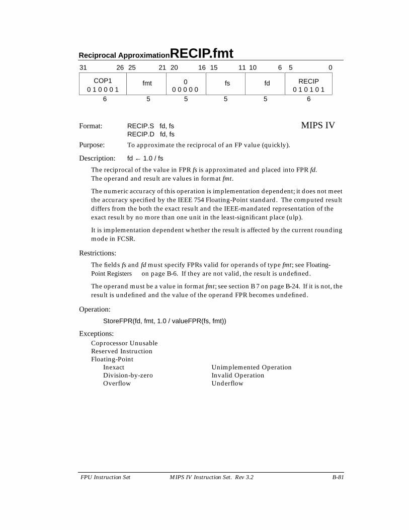
Reciprocal Approximation RECIP.fmt
FPU Instruction Set MIPS IV Instruction Set. Rev 3.2 B-81
Format: RECIP.S fd, fs MIPS IVRECIP.D fd, fs
Purpose: To approximate the reciprocal of an FP value (quickly).
Description: fd ← 1.0 / fs
The reciprocal of the value in FPR fs is approximated and placed into FPR fd.The operand and result are values in format fmt.
The numeric accuracy of this operation is implementation dependent; it does not meetthe accuracy specified by the IEEE 754 Floating-Point standard. The computed resultdiffers from the both the exact result and the IEEE-mandated representation of theexact result by no more than one unit in the least-significant place (ulp).
It is implementation dependent whether the result is affected by the current roundingmode in FCSR.
Restrictions:
The fields fs and fd must specify FPRs valid for operands of type fmt; see Floating-Point Registers on page B-6. If they are not valid, the result is undefined.
The operand must be a value in format fmt; see section B 7 on page B-24. If it is not, theresult is undefined and the value of the operand FPR becomes undefined.
Operation:
StoreFPR(fd, fmt, 1.0 / valueFPR(fs, fmt))
Exceptions:Coprocessor UnusableReserved InstructionFloating-Point
Inexact Unimplemented OperationDivision-by-zero Invalid OperationOverflow Underflow
31 2526 2021 1516
COP1 fmt 0
6 5 5
fs fd RECIP
5 5 6
11 10 6 5 0
0 1 0 0 0 1 0 1 0 1 0 10 0 0 0 0
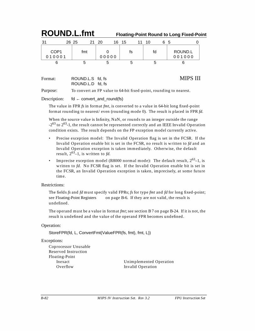
ROUND.L.fmt Floating-Point Round to Long Fixed-Point
B-82 MIPS IV Instruction Set. Rev 3.2 FPU Instruction Set
Format: ROUND.L.S fd, fs MIPS IIIROUND.L.D fd, fs
Purpose: To convert an FP value to 64-bit fixed-point, rounding to nearest.
Description: fd ← convert_and_round(fs)
The value in FPR fs in format fmt, is converted to a value in 64-bit long fixed-pointformat rounding to nearest/even (rounding mode 0). The result is placed in FPR fd.
When the source value is Infinity, NaN, or rounds to an integer outside the range-263 to 263-1, the result cannot be represented correctly and an IEEE Invalid Operationcondition exists. The result depends on the FP exception model currently active.
• Precise exception model: The Invalid Operation flag is set in the FCSR. If theInvalid Operation enable bit is set in the FCSR, no result is written to fd and anInvalid Operation exception is taken immediately. Otherwise, the defaultresult, 263–1, is written to fd.
• Imprecise exception model (R8000 normal mode): The default result, 263–1, iswritten to fd. No FCSR flag is set. If the Invalid Operation enable bit is set inthe FCSR, an Invalid Operation exception is taken, imprecisely, at some futuretime.
Restrictions:
The fields fs and fd must specify valid FPRs; fs for type fmt and fd for long fixed-point;see Floating-Point Registers on page B-6. If they are not valid, the result isundefined.
The operand must be a value in format fmt; see section B 7 on page B-24. If it is not, theresult is undefined and the value of the operand FPR becomes undefined.
Operation:
StoreFPR(fd, L, ConvertFmt(ValueFPR(fs, fmt), fmt, L))
Exceptions:Coprocessor UnusableReserved InstructionFloating-Point
Inexact Unimplemented OperationOverflow Invalid Operation
31 0
6 5 5 5 5 6
COP1 fmt 0 fs fd ROUND.L
11 1021 20 16 1526 25 6 5
0 1 0 0 0 1 0 0 0 0 0 0 0 1 0 0 0
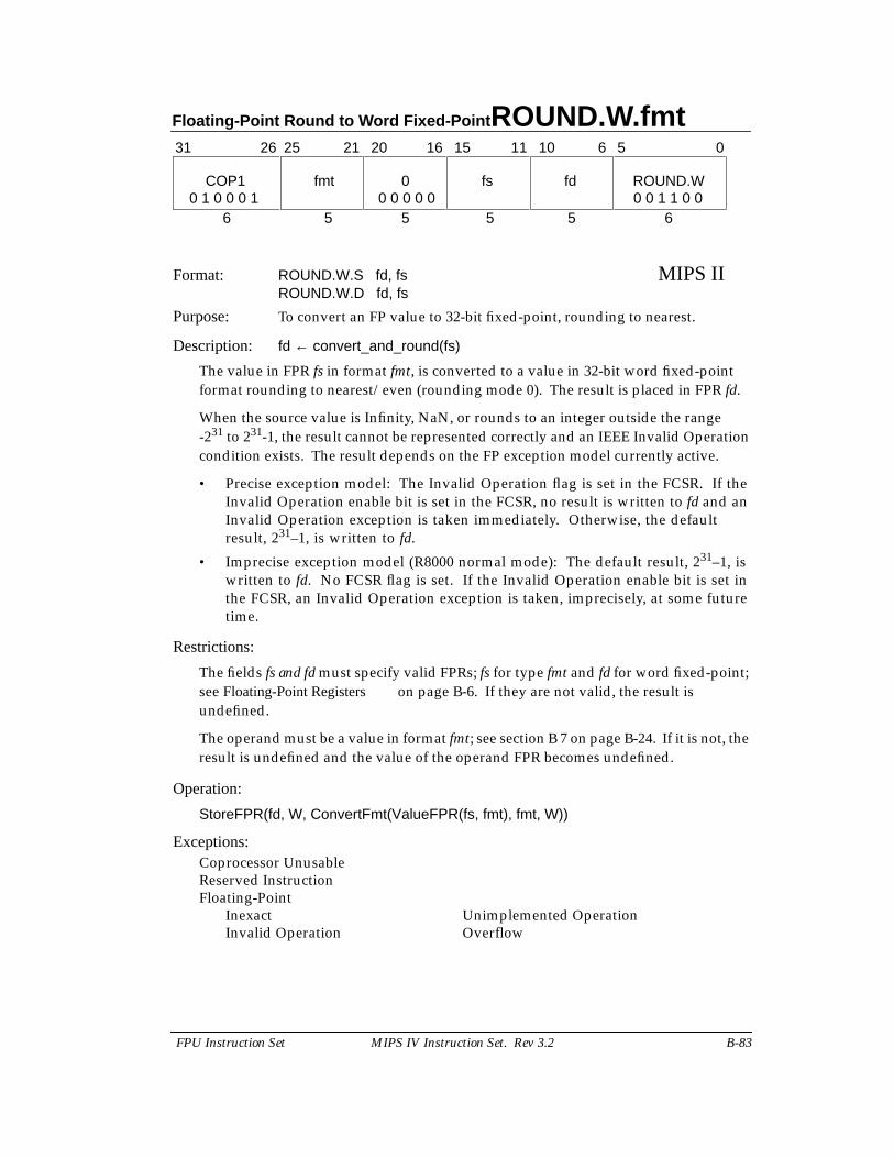
Floating-Point Round to Word Fixed-Point ROUND.W.fmt
FPU Instruction Set MIPS IV Instruction Set. Rev 3.2 B-83
Format: ROUND.W.S fd, fs MIPS IIROUND.W.D fd, fs
Purpose: To convert an FP value to 32-bit fixed-point, rounding to nearest.
Description: fd ← convert_and_round(fs)
The value in FPR fs in format fmt, is converted to a value in 32-bit word fixed-pointformat rounding to nearest/even (rounding mode 0). The result is placed in FPR fd.
When the source value is Infinity, NaN, or rounds to an integer outside the range-231 to 231-1, the result cannot be represented correctly and an IEEE Invalid Operationcondition exists. The result depends on the FP exception model currently active.
• Precise exception model: The Invalid Operation flag is set in the FCSR. If theInvalid Operation enable bit is set in the FCSR, no result is written to fd and anInvalid Operation exception is taken immediately. Otherwise, the defaultresult, 231–1, is written to fd.
• Imprecise exception model (R8000 normal mode): The default result, 231–1, iswritten to fd. No FCSR flag is set. If the Invalid Operation enable bit is set inthe FCSR, an Invalid Operation exception is taken, imprecisely, at some futuretime.
Restrictions:
The fields fs and fd must specify valid FPRs; fs for type fmt and fd for word fixed-point;see Floating-Point Registers on page B-6. If they are not valid, the result isundefined.
The operand must be a value in format fmt; see section B 7 on page B-24. If it is not, theresult is undefined and the value of the operand FPR becomes undefined.
Operation:
StoreFPR(fd, W, ConvertFmt(ValueFPR(fs, fmt), fmt, W))
Exceptions:Coprocessor UnusableReserved InstructionFloating-Point
Inexact Unimplemented OperationInvalid Operation Overflow
31 0
6 5 5 5 5 6
COP1 fmt 0 fs fd ROUND.W
11 1021 20 16 1526 25 6 5
0 1 0 0 0 1 0 0 1 1 0 00 0 0 0 0
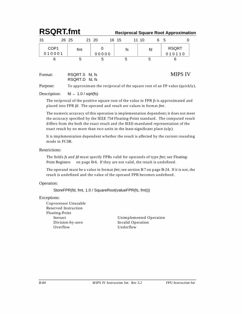
RSQRT.fmt Reciprocal Square Root Approximation
B-84 MIPS IV Instruction Set. Rev 3.2 FPU Instruction Set
Format: RSQRT.S fd, fs MIPS IVRSQRT.D fd, fs
Purpose: To approximate the reciprocal of the square root of an FP value (quickly).
Description: fd ← 1.0 / sqrt(fs)
The reciprocal of the positive square root of the value in FPR fs is approximated andplaced into FPR fd. The operand and result are values in format fmt.
The numeric accuracy of this operation is implementation dependent; it does not meetthe accuracy specified by the IEEE 754 Floating-Point standard. The computed resultdiffers from the both the exact result and the IEEE-mandated representation of theexact result by no more than two units in the least-significant place (ulp).
It is implementation dependent whether the result is affected by the current roundingmode in FCSR.
Restrictions:
The fields fs and fd must specify FPRs valid for operands of type fmt; see Floating-Point Registers on page B-6. If they are not valid, the result is undefined.
The operand must be a value in format fmt; see section B 7 on page B-24. If it is not, theresult is undefined and the value of the operand FPR becomes undefined.
Operation:
StoreFPR(fd, fmt, 1.0 / SquareRoot(valueFPR(fs, fmt)))
Exceptions:Coprocessor UnusableReserved InstructionFloating-Point
Inexact Unimplemented OperationDivision-by-zero Invalid OperationOverflow Underflow
31 2526 2021 1516
COP1 fmt 0
6 5 5
fs fd RSQRT
5 5 6
11 10 6 5 0
0 1 0 1 1 00 1 0 0 0 1 0 0 0 0 0
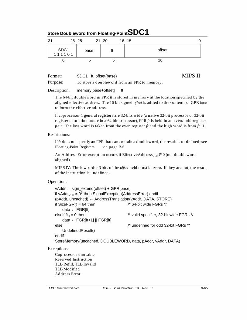
Store Doubleword from Floating-Point SDC1
FPU Instruction Set MIPS IV Instruction Set. Rev 3.2 B-85
Format: SDC1 ft, offset(base) MIPS IIPurpose: To store a doubleword from an FPR to memory.
Description: memory[base+offset] ← ft
The 64-bit doubleword in FPR ft is stored in memory at the location specified by thealigned effective address. The 16-bit signed offset is added to the contents of GPR baseto form the effective address.
If coprocessor 1 general registers are 32-bits wide (a native 32-bit processor or 32-bitregister emulation mode in a 64-bit processor), FPR ft is held in an even/odd registerpair. The low word is taken from the even register ft and the high word is from ft+1.
Restrictions:
If ft does not specify an FPR that can contain a doubleword, the result is undefined; seeFloating-Point Registers on page B-6.
An Address Error exception occurs if EffectiveAddress2..0 ≠ 0 (not doubleword-aligned).
MIPS IV: The low-order 3 bits of the offset field must be zero. If they are not, the resultof the instruction is undefined.
Operation:
vAddr ← sign_extend(offset) + GPR[base]if vAddr2..0 ≠ 03 then SignalException(AddressError) endif(pAddr, uncached) ← AddressTranslation(vAddr, DATA, STORE)if SizeFGR() = 64 then /* 64-bit wide FGRs */
data ← FGR[ft]elseif ft0 = 0 then /* valid specifier, 32-bit wide FGRs */
data ← FGR[ft+1] || FGR[ft]else /* undefined for odd 32-bit FGRs */
UndefinedResult()endifStoreMemory(uncached, DOUBLEWORD, data, pAddr, vAddr, DATA)
Exceptions:Coprocessor unusableReserved InstructionTLB Refill, TLB InvalidTLB ModifiedAddress Error
31 2526 2021 1516 0
SDC1 base ft offset
6 5 5 161 1 1 1 0 1
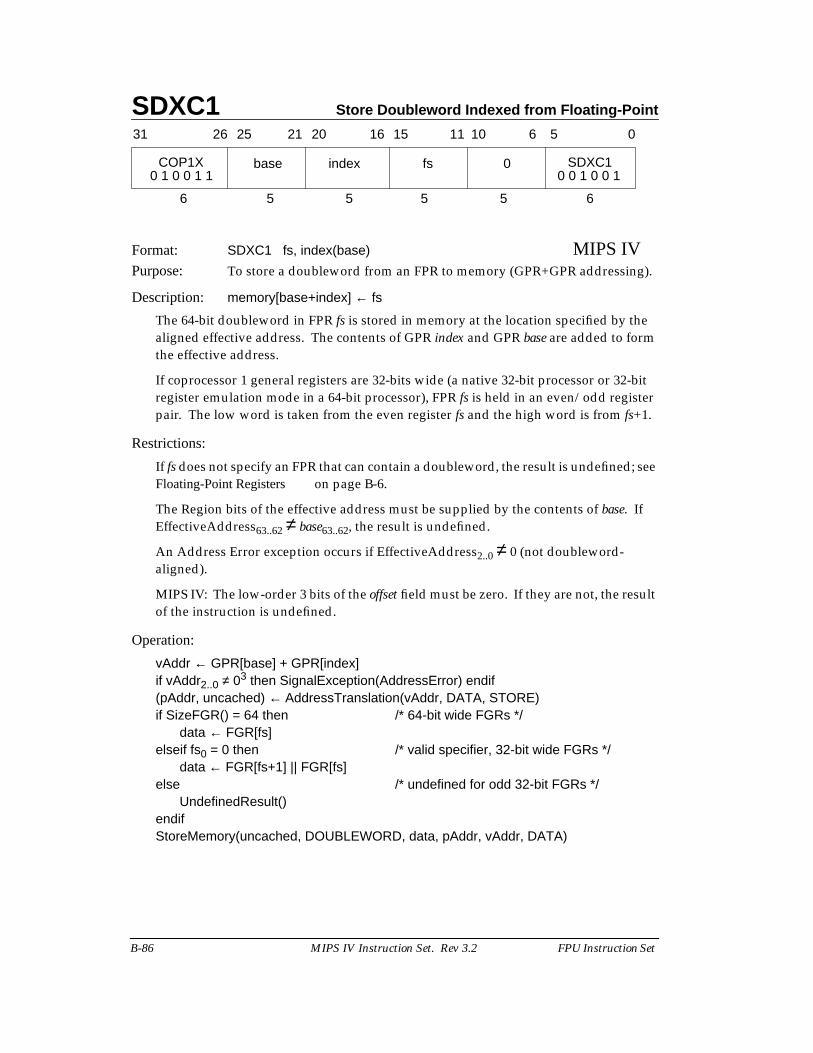
SDXC1 Store Doubleword Indexed from Floating-Point
B-86 MIPS IV Instruction Set. Rev 3.2 FPU Instruction Set
Format: SDXC1 fs, index(base) MIPS IVPurpose: To store a doubleword from an FPR to memory (GPR+GPR addressing).
Description: memory[base+index] ← fs
The 64-bit doubleword in FPR fs is stored in memory at the location specified by thealigned effective address. The contents of GPR index and GPR base are added to formthe effective address.
If coprocessor 1 general registers are 32-bits wide (a native 32-bit processor or 32-bitregister emulation mode in a 64-bit processor), FPR fs is held in an even/odd registerpair. The low word is taken from the even register fs and the high word is from fs+1.
Restrictions:
If fs does not specify an FPR that can contain a doubleword, the result is undefined; seeFloating-Point Registers on page B-6.
The Region bits of the effective address must be supplied by the contents of base. IfEffectiveAddress63..62 ≠ base63..62, the result is undefined.
An Address Error exception occurs if EffectiveAddress2..0 ≠ 0 (not doubleword-aligned).
MIPS IV: The low-order 3 bits of the offset field must be zero. If they are not, the resultof the instruction is undefined.
Operation:
vAddr ← GPR[base] + GPR[index]if vAddr2..0 ≠ 03 then SignalException(AddressError) endif(pAddr, uncached) ← AddressTranslation(vAddr, DATA, STORE)if SizeFGR() = 64 then /* 64-bit wide FGRs */
data ← FGR[fs]elseif fs0 = 0 then /* valid specifier, 32-bit wide FGRs */
data ← FGR[fs+1] || FGR[fs]else /* undefined for odd 32-bit FGRs */
UndefinedResult()endifStoreMemory(uncached, DOUBLEWORD, data, pAddr, vAddr, DATA)
31 2526 2021 1516
COP1X base index
6 5 5
fs 0 SDXC1
5 5 6
11 10 6 5 0
0 0 1 0 0 10 1 0 0 1 1
Store Doubleword Indexed from Floating-Point SDXC1
FPU Instruction Set MIPS IV Instruction Set. Rev 3.2 B-87
Exceptions:TLB Refill, TLB InvalidTLB ModifiedAddress ErrorReserved InstructionCoprocessor Unusable
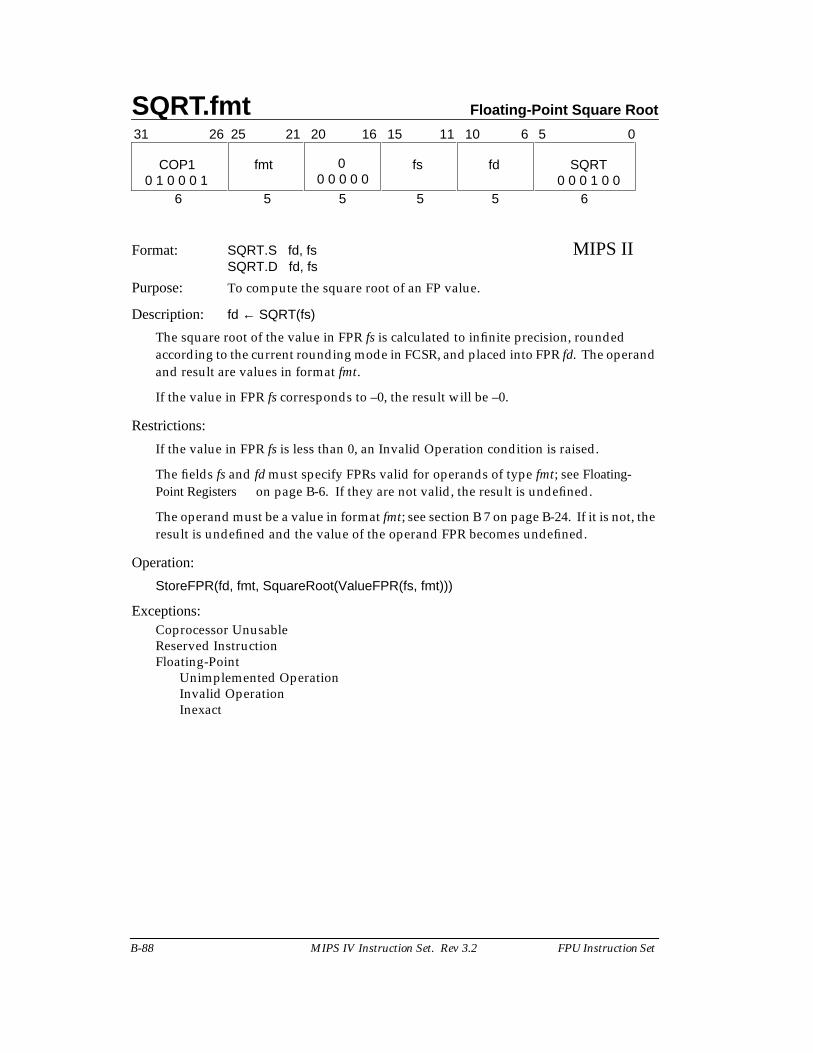
SQRT.fmt Floating-Point Square Root
B-88 MIPS IV Instruction Set. Rev 3.2 FPU Instruction Set
Format: SQRT.S fd, fs MIPS IISQRT.D fd, fs
Purpose: To compute the square root of an FP value.
Description: fd ← SQRT(fs)
The square root of the value in FPR fs is calculated to infinite precision, roundedaccording to the current rounding mode in FCSR, and placed into FPR fd. The operandand result are values in format fmt.
If the value in FPR fs corresponds to –0, the result will be –0.
Restrictions:
If the value in FPR fs is less than 0, an Invalid Operation condition is raised.
The fields fs and fd must specify FPRs valid for operands of type fmt; see Floating-Point Registers on page B-6. If they are not valid, the result is undefined.
The operand must be a value in format fmt; see section B 7 on page B-24. If it is not, theresult is undefined and the value of the operand FPR becomes undefined.
Operation:
StoreFPR(fd, fmt, SquareRoot(ValueFPR(fs, fmt)))
Exceptions:Coprocessor UnusableReserved InstructionFloating-Point
Unimplemented OperationInvalid OperationInexact
31 0
6 5 5 5 5 6
COP1 fmt fs fd SQRT
11 1021 20 16 1526 25 6 5
0 1 0 0 0 1 0 0 0 1 0 00
0 0 0 0 0
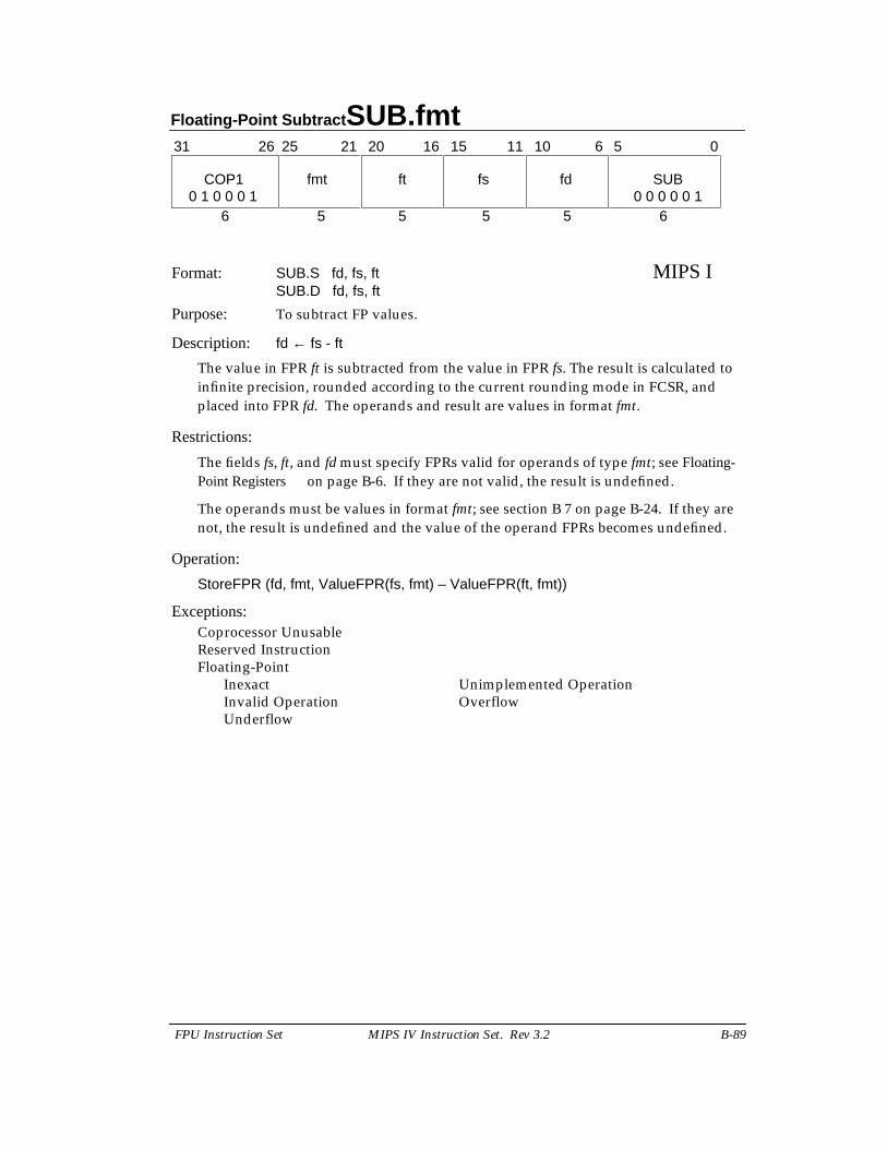
Floating-Point Subtract SUB.fmt
FPU Instruction Set MIPS IV Instruction Set. Rev 3.2 B-89
Format: SUB.S fd, fs, ft MIPS ISUB.D fd, fs, ft
Purpose: To subtract FP values.
Description: fd ← fs - ft
The value in FPR ft is subtracted from the value in FPR fs. The result is calculated toinfinite precision, rounded according to the current rounding mode in FCSR, andplaced into FPR fd. The operands and result are values in format fmt.
Restrictions:
The fields fs, ft, and fd must specify FPRs valid for operands of type fmt; see Floating-Point Registers on page B-6. If they are not valid, the result is undefined.
The operands must be values in format fmt; see section B 7 on page B-24. If they arenot, the result is undefined and the value of the operand FPRs becomes undefined.
Operation:
StoreFPR (fd, fmt, ValueFPR(fs, fmt) – ValueFPR(ft, fmt))
Exceptions:Coprocessor UnusableReserved InstructionFloating-Point
Inexact Unimplemented OperationInvalid Operation OverflowUnderflow
31 0
6 5 5 5 5 6
COP1 fmt ft fs fd SUB
11 1021 20 16 1526 25 6 5
0 1 0 0 0 1 0 0 0 0 0 1
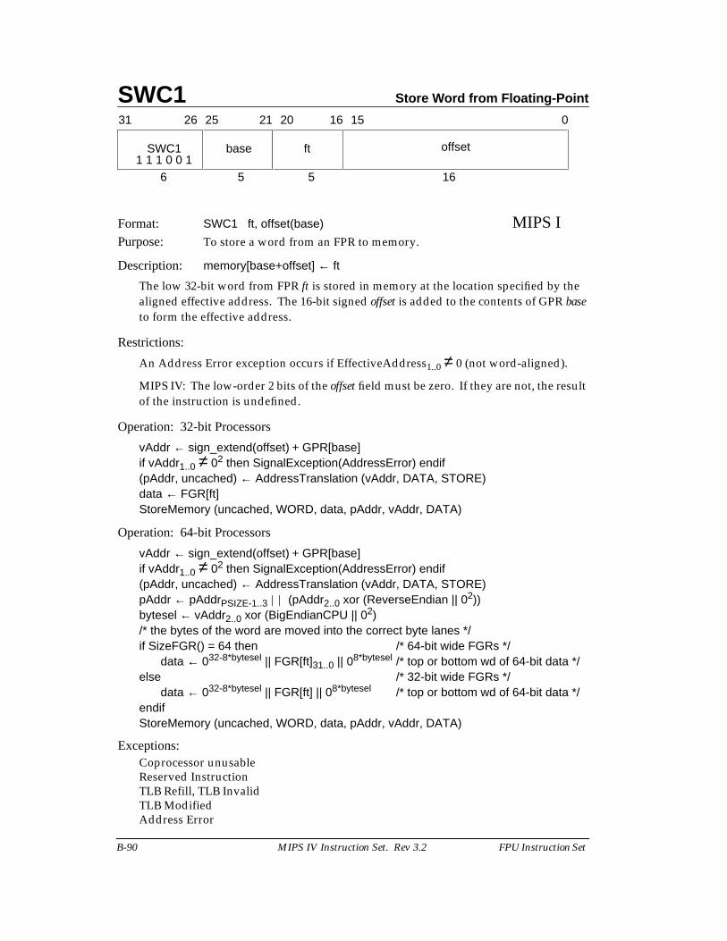
SWC1 Store Word from Floating-Point
B-90 MIPS IV Instruction Set. Rev 3.2 FPU Instruction Set
Format: SWC1 ft, offset(base) MIPS IPurpose: To store a word from an FPR to memory.
Description: memory[base+offset] ← ft
The low 32-bit word from FPR ft is stored in memory at the location specified by thealigned effective address. The 16-bit signed offset is added to the contents of GPR baseto form the effective address.
Restrictions:
An Address Error exception occurs if EffectiveAddress1..0 ≠ 0 (not word-aligned).
MIPS IV: The low-order 2 bits of the offset field must be zero. If they are not, the resultof the instruction is undefined.
Operation: 32-bit Processors
vAddr ← sign_extend(offset) + GPR[base]if vAddr1..0 ≠ 02 then SignalException(AddressError) endif(pAddr, uncached) ← AddressTranslation (vAddr, DATA, STORE)data ← FGR[ft]StoreMemory (uncached, WORD, data, pAddr, vAddr, DATA)
Operation: 64-bit Processors
vAddr ← sign_extend(offset) + GPR[base]if vAddr1..0 ≠ 02 then SignalException(AddressError) endif(pAddr, uncached) ← AddressTranslation (vAddr, DATA, STORE)pAddr ← pAddrPSIZE-1..3 || (pAddr2..0 xor (ReverseEndian || 02))bytesel ← vAddr2..0 xor (BigEndianCPU || 02)/* the bytes of the word are moved into the correct byte lanes */if SizeFGR() = 64 then /* 64-bit wide FGRs */
data ← 032-8*bytesel || FGR[ft]31..0 || 08*bytesel /* top or bottom wd of 64-bit data */else /* 32-bit wide FGRs */
data ← 032-8*bytesel || FGR[ft] || 08*bytesel /* top or bottom wd of 64-bit data */endifStoreMemory (uncached, WORD, data, pAddr, vAddr, DATA)
Exceptions:Coprocessor unusableReserved InstructionTLB Refill, TLB InvalidTLB ModifiedAddress Error
31 2526 2021 1516 0
SWC1 base ft offset
6 5 5 161 1 1 0 0 1
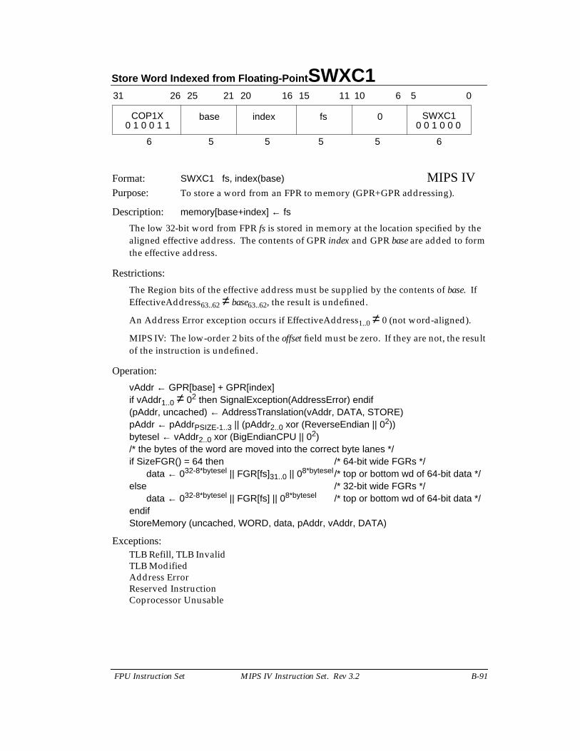
Store Word Indexed from Floating-Point SWXC1
FPU Instruction Set MIPS IV Instruction Set. Rev 3.2 B-91
Format: SWXC1 fs, index(base) MIPS IVPurpose: To store a word from an FPR to memory (GPR+GPR addressing).
Description: memory[base+index] ← fs
The low 32-bit word from FPR fs is stored in memory at the location specified by thealigned effective address. The contents of GPR index and GPR base are added to formthe effective address.
Restrictions:
The Region bits of the effective address must be supplied by the contents of base. IfEffectiveAddress63..62 ≠ base63..62, the result is undefined.
An Address Error exception occurs if EffectiveAddress1..0 ≠ 0 (not word-aligned).
MIPS IV: The low-order 2 bits of the offset field must be zero. If they are not, the resultof the instruction is undefined.
Operation:
vAddr ← GPR[base] + GPR[index]if vAddr1..0 ≠ 02 then SignalException(AddressError) endif(pAddr, uncached) ← AddressTranslation(vAddr, DATA, STORE)pAddr ← pAddrPSIZE-1..3 || (pAddr2..0 xor (ReverseEndian || 02))bytesel ← vAddr2..0 xor (BigEndianCPU || 02)/* the bytes of the word are moved into the correct byte lanes */if SizeFGR() = 64 then /* 64-bit wide FGRs */
data ← 032-8*bytesel || FGR[fs]31..0 || 08*bytesel/* top or bottom wd of 64-bit data */else /* 32-bit wide FGRs */
data ← 032-8*bytesel || FGR[fs] || 08*bytesel /* top or bottom wd of 64-bit data */endifStoreMemory (uncached, WORD, data, pAddr, vAddr, DATA)
Exceptions:TLB Refill, TLB InvalidTLB ModifiedAddress ErrorReserved InstructionCoprocessor Unusable
31 2526 2021 1516
COP1X base index
6 5 5
fs 0 SWXC1
5 5 6
11 10 6 5 0
0 0 1 0 0 00 1 0 0 1 1
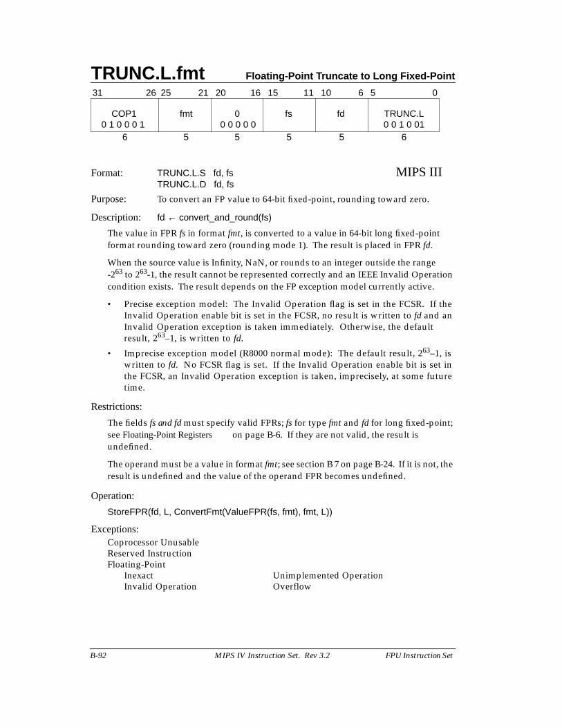
TRUNC.L.fmt Floating-Point Truncate to Long Fixed-Point
B-92 MIPS IV Instruction Set. Rev 3.2 FPU Instruction Set
Format: TRUNC.L.S fd, fs MIPS IIITRUNC.L.D fd, fs
Purpose: To convert an FP value to 64-bit fixed-point, rounding toward zero.
Description: fd ← convert_and_round(fs)
The value in FPR fs in format fmt, is converted to a value in 64-bit long fixed-pointformat rounding toward zero (rounding mode 1). The result is placed in FPR fd.
When the source value is Infinity, NaN, or rounds to an integer outside the range-263 to 263-1, the result cannot be represented correctly and an IEEE Invalid Operationcondition exists. The result depends on the FP exception model currently active.
• Precise exception model: The Invalid Operation flag is set in the FCSR. If theInvalid Operation enable bit is set in the FCSR, no result is written to fd and anInvalid Operation exception is taken immediately. Otherwise, the defaultresult, 263–1, is written to fd.
• Imprecise exception model (R8000 normal mode): The default result, 263–1, iswritten to fd. No FCSR flag is set. If the Invalid Operation enable bit is set inthe FCSR, an Invalid Operation exception is taken, imprecisely, at some futuretime.
Restrictions:
The fields fs and fd must specify valid FPRs; fs for type fmt and fd for long fixed-point;see Floating-Point Registers on page B-6. If they are not valid, the result isundefined.
The operand must be a value in format fmt; see section B 7 on page B-24. If it is not, theresult is undefined and the value of the operand FPR becomes undefined.
Operation:
StoreFPR(fd, L, ConvertFmt(ValueFPR(fs, fmt), fmt, L))
Exceptions:Coprocessor UnusableReserved InstructionFloating-Point
Inexact Unimplemented OperationInvalid Operation Overflow
31 0
6 5 5 5 5 6
COP1 fmt 0 fs fd TRUNC.L
11 1021 20 16 1526 25 6 5
0 1 0 0 0 1 0 0 0 0 0 0 0 1 0 01
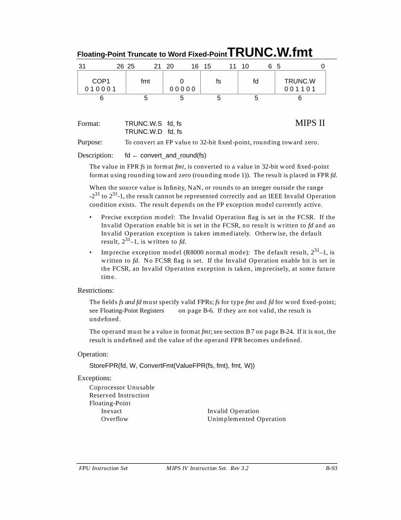
Floating-Point Truncate to Word Fixed-Point TRUNC.W.fmt
FPU Instruction Set MIPS IV Instruction Set. Rev 3.2 B-93
Format: TRUNC.W.S fd, fs MIPS IITRUNC.W.D fd, fs
Purpose: To convert an FP value to 32-bit fixed-point, rounding toward zero.
Description: fd ← convert_and_round(fs)
The value in FPR fs in format fmt, is converted to a value in 32-bit word fixed-pointformat using rounding toward zero (rounding mode 1)). The result is placed in FPR fd.
When the source value is Infinity, NaN, or rounds to an integer outside the range-231 to 231-1, the result cannot be represented correctly and an IEEE Invalid Operationcondition exists. The result depends on the FP exception model currently active.
• Precise exception model: The Invalid Operation flag is set in the FCSR. If theInvalid Operation enable bit is set in the FCSR, no result is written to fd and anInvalid Operation exception is taken immediately. Otherwise, the defaultresult, 231–1, is written to fd.
• Imprecise exception model (R8000 normal mode): The default result, 231–1, iswritten to fd. No FCSR flag is set. If the Invalid Operation enable bit is set inthe FCSR, an Invalid Operation exception is taken, imprecisely, at some futuretime.
Restrictions:
The fields fs and fd must specify valid FPRs; fs for type fmt and fd for word fixed-point;see Floating-Point Registers on page B-6. If they are not valid, the result isundefined.
The operand must be a value in format fmt; see section B 7 on page B-24. If it is not, theresult is undefined and the value of the operand FPR becomes undefined.
Operation:
StoreFPR(fd, W, ConvertFmt(ValueFPR(fs, fmt), fmt, W))
Exceptions:Coprocessor UnusableReserved InstructionFloating-Point
Inexact Invalid OperationOverflow Unimplemented Operation
31 0
6 5 5 5 5 6
COP1 fmt 0 fs fd TRUNC.W
11 1021 20 16 1526 25 6 5
0 1 0 0 0 1 0 0 1 1 0 10 0 0 0 0
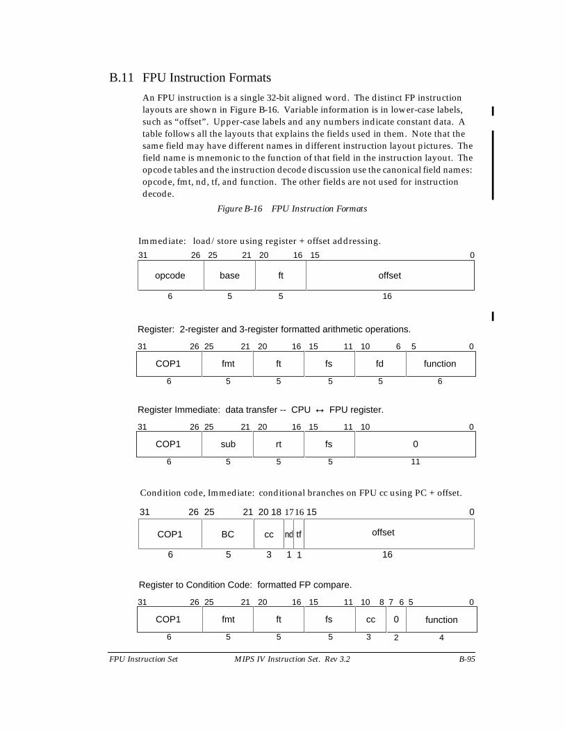
FPU Instruction Set MIPS IV Instruction Set. Rev 3.2 B-95
B.11 FPU Instruction Formats
An FPU instruction is a single 32-bit aligned word. The distinct FP instructionlayouts are shown in Figure B-16. Variable information is in lower-case labels,such as “offset”. Upper-case labels and any numbers indicate constant data. Atable follows all the layouts that explains the fields used in them. Note that thesame field may have different names in different instruction layout pictures. Thefield name is mnemonic to the function of that field in the instruction layout. Theopcode tables and the instruction decode discussion use the canonical field names:opcode, fmt, nd, tf, and function. The other fields are not used for instructiondecode.
Figure B-16 FPU Instruction Formats
31 25 21 20 16 015
offset
26
ftbaseopcode
6 5 5 16
Immediate: load/store using register + offset addressing.
31 0
6 5 5 5 5 6
COP1 fmt ft fs fd function
11 1021 20 16 1526 25 6 5
Register: 2-register and 3-register formatted arithmetic operations.
31 0
6 5 5 5 11
COP1 sub rt fs 0
11 1021 20 16 1526 25
Register Immediate: data transfer -- CPU ↔ FPU register.
15
BC
31 2526
COP1
6
0
16
offset
21 20
5 3
ndcc
1 1
tf
18
Condition code, Immediate: conditional branches on FPU cc using PC + offset.
1716
31 0
6 5 5 5 3
COP1 fmt ft fs cc
11 1021 20 16 1526 25 6 5
0
2
78
4
Register to Condition Code: formatted FP compare.
function
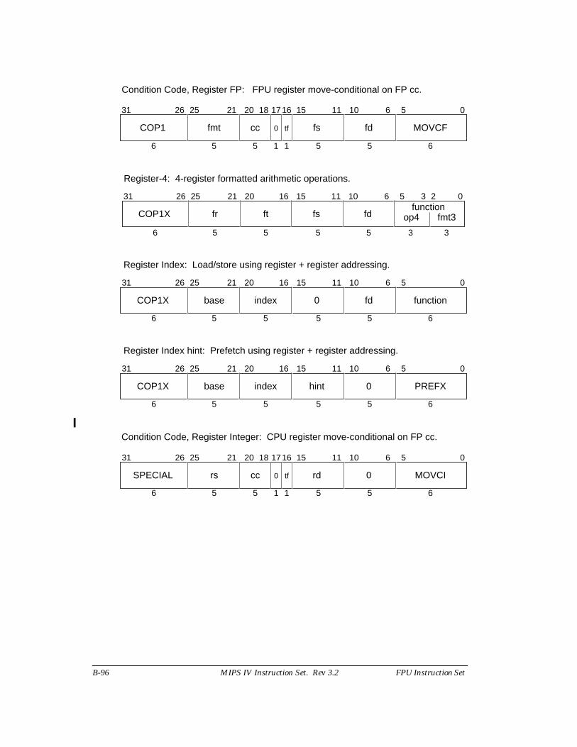
B-96 MIPS IV Instruction Set. Rev 3.2 FPU Instruction Set
31 0
6 5 5 5 5 6
COP1 fmt cc fs fd MOVCF
11 1021 20 1526 25 6 5
11
18
0 tf
Condition Code, Register FP: FPU register move-conditional on FP cc.
1716
31 0
6 5 5 5 5 3
COP1X fr ft fs fd op4
11 1021 20 16 1526 25 6 5
fmt3
3
23function
Register-4: 4-register formatted arithmetic operations.
31 0
6 5 5 5 5 6
COP1X base index 0 fd function
11 1021 20 16 1526 25 6 5
Register Index: Load/store using register + register addressing.
31 0
6 5 5 5 5 6
COP1X base index hint 0 PREFX
11 1021 20 16 1526 25 6 5
Register Index hint: Prefetch using register + register addressing.
31 0
6 5 5 5 5 6
SPECIAL rs cc rd 0 MOVCI
11 1021 20 1526 25 6 5
11
18
0 tf
Condition Code, Register Integer: CPU register move-conditional on FP cc.
1716
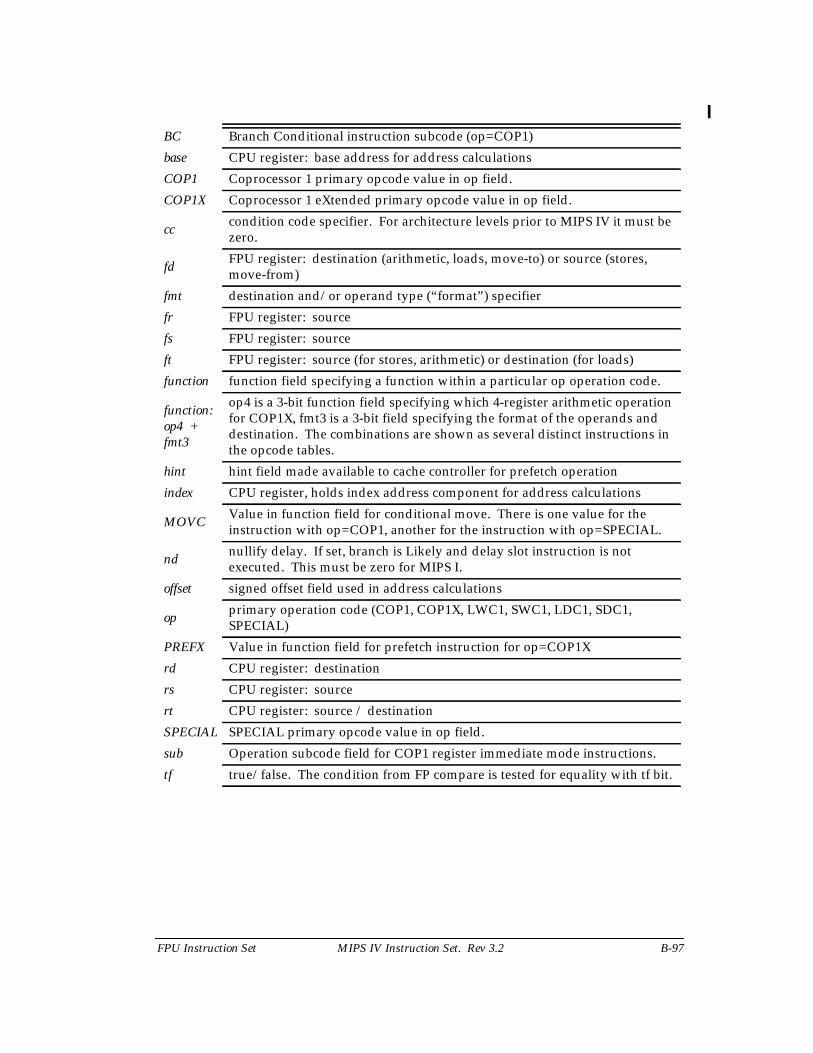
FPU Instruction Set MIPS IV Instruction Set. Rev 3.2 B-97
BC Branch Conditional instruction subcode (op=COP1)
base CPU register: base address for address calculations
COP1 Coprocessor 1 primary opcode value in op field.
COP1X Coprocessor 1 eXtended primary opcode value in op field.
cccondition code specifier. For architecture levels prior to MIPS IV it must bezero.
fdFPU register: destination (arithmetic, loads, move-to) or source (stores,move-from)
fmt destination and/or operand type (“format”) specifier
fr FPU register: source
fs FPU register: source
ft FPU register: source (for stores, arithmetic) or destination (for loads)
function function field specifying a function within a particular op operation code.
function:op4 +fmt3
op4 is a 3-bit function field specifying which 4-register arithmetic operationfor COP1X, fmt3 is a 3-bit field specifying the format of the operands anddestination. The combinations are shown as several distinct instructions inthe opcode tables.
hint hint field made available to cache controller for prefetch operation
index CPU register, holds index address component for address calculations
MOVCValue in function field for conditional move. There is one value for theinstruction with op=COP1, another for the instruction with op=SPECIAL.
ndnullify delay. If set, branch is Likely and delay slot instruction is notexecuted. This must be zero for MIPS I.
offset signed offset field used in address calculations
opprimary operation code (COP1, COP1X, LWC1, SWC1, LDC1, SDC1,SPECIAL)
PREFX Value in function field for prefetch instruction for op=COP1X
rd CPU register: destination
rs CPU register: source
rt CPU register: source / destination
SPECIAL SPECIAL primary opcode value in op field.
sub Operation subcode field for COP1 register immediate mode instructions.
tf true/false. The condition from FP compare is tested for equality with tf bit.
B-98 MIPS IV Instruction Set. Rev 3.2 FPU Instruction Set
B.12 FPU (CP1) Instruction Opcode Bit Encoding
This section describes the encoding of the Floating-Point Unit (FPU) instructionsfor the four levels of the MIPS architecture, MIPS I through MIPS IV. Each architecturelevel includes the instructions in the previous level;† MIPS IV includes all instructions inMIPS I, MIPS II, and MIPS III. This section presents eight different views of the instructionencoding.
• Separate encoding tables for each architecture level.
• A MIPS IV encoding table showing the architecture level at which eachopcode was originally defined and subsequently modified (if modified).
• Separate encoding tables for each architecture revision showing thechanges made during that revision.
B 12.1 Instruction Decode
Instruction field names are printed in bold in this section.
The primary opcode field is decoded first. The opcode values LWC1, SWC1,LDC1, and SDC1 fully specify FPU load and store instructions. The opcode values COP1,COP1X, and SPECIAL specify instruction classes. Instructions within a class are furtherspecified by values in other fields.
B 12.1.1 COP1 Instruction Class
The opcode =COP1 instruction class encodes most of the FPU instructions. Theclass is further decoded by examining the fmt field. The fmt values fully specify theCPU ↔ FPU register move instructions and specify the S, D, W, L, and BC instructionclasses.
The opcode =COP1 + fmt =BC instruction class encodes the conditional branchinstructions. The class is further decoded, and the instructions fully specified, byexamining the nd and tf fields.
The opcode =COP1 + fmt =(S, D, W, or L) instruction classes encode instructionsthat operate on formatted (typed) operands. Each of these instruction classes is furtherdecoded by examining the function field. With one exception the function values fullyspecify instructions. The exception is the MOVCF instruction class.
The opcode =COP1 + fmt =(S or D) + function =MOVCF instruction class encodesthe MOVT.fmt and MOVF.fmt conditional move instructions (to move FP values based onFP condition codes). The class is further decoded, and the instructions fully specified, byexamining the tf field.
† An exception to this rule is that the reserved, but never implemented, Coprocessor 3instructions were removed or changed to another use starting in MIPS III.
FPU Instruction Set MIPS IV Instruction Set. Rev 3.2 B-99
B 12.1.2 COP1X Instruction Class
The opcode =COP1X instruction class encodes the indexed load/storeinstructions, the indexed prefetch, and the multiply accumulate instructions. The class isfurther decoded, and the instructions fully specified, by examining the function field.
B 12.1.3 SPECIAL Instruction Class
The opcode =SPECIAL instruction class is further decoded by examining thefunction field. The only function value that applies to FPU instruction encoding is theMOVCI instruction class. The remainder of the function values encode CPU instructions.
The opcode =SPECIAL + function =MOVCI instruction class encodes the MOVTand MOVF conditional move instructions (to move CPU registers based on FP conditioncodes). The class is further decoded, and the instructions fully specified, by examining thetf field.
B 12.2 Instruction Subsets of MIPS III and MIPS IV Processors.
MIPS III processors, such as the R4000, R4200, R4300, R4400, and R4600, have aprocessor mode in which only the MIPS II instructions are valid. The MIPS II encodingtable describes the MIPS II-only mode.
MIPS IV processors, such as the R8000 and R10000, have processor modes in whichonly the MIPS II or MIPS III instructions are valid. The MIPS II encoding table describesthe MIPS II-only mode. The MIPS III encoding table describes the MIPS III-only mode.
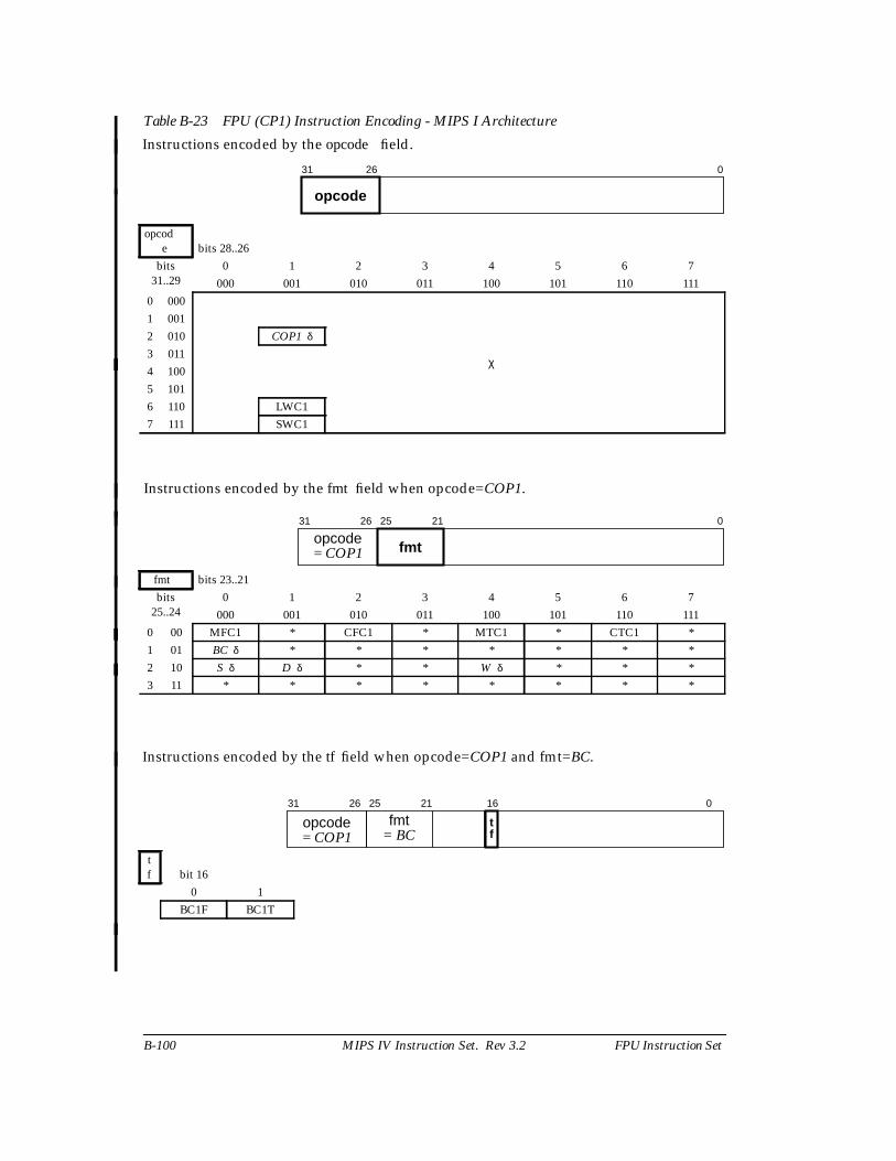
B-100 MIPS IV Instruction Set. Rev 3.2 FPU Instruction Set
Table B-23 FPU (CP1) Instruction Encoding - MIPS I Architecture
Instructions encoded by the opcode field.
opcode bits 28..26
bits31..29
0 1 2 3 4 5 6 7000 001 010 011 100 101 110 111
0 000
χ
1 0012 010 COP1 δ
3 0114 1005 1016 110 LWC17 111 SWC1
Instructions encoded by the fmt field when opcode=COP1.
fmt bits 23..21bits
25..240 1 2 3 4 5 6 7
000 001 010 011 100 101 110 1110 00 MFC1 * CFC1 * MTC1 * CTC1 *1 01 BC δ * * * * * * *2 10 S δ D δ * * W δ * * *3 11 * * * * * * * *
Instructions encoded by the tf field when opcode=COP1 and fmt=BC.
tf bit 16
0 1BC1F BC1T
31 26
opcode
0
31 26
opcode 25 21
fmt
0
= COP1
31 26
opcode 25 21
fmt16
tf
0
= BC= COP1
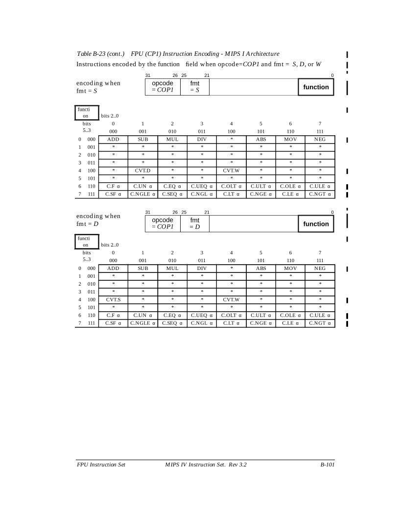
FPU Instruction Set MIPS IV Instruction Set. Rev 3.2 B-101
Table B-23 (cont.) FPU (CP1) Instruction Encoding - MIPS I Architecture
Instructions encoded by the function field when opcode=COP1 and fmt = S, D, or W
encoding whenfmt = S
function bits 2..0bits5..3
0 1 2 3 4 5 6 7000 001 010 011 100 101 110 111
0 000 ADD SUB MUL DIV * ABS MOV NEG1 001 * * * * * * * *2 010 * * * * * * * *3 011 * * * * * * * *4 100 * CVT.D * * CVT.W * * *5 101 * * * * * * * *6 110 C.F α C.UN α C.EQ α C.UEQ α C.OLT α C.ULT α C.OLE α C.ULE α
7 111 C.SF α C.NGLE α C.SEQ α C.NGL α C.LT α C.NGE α C.LE α C.NGT α
encoding whenfmt = D
function bits 2..0bits5..3
0 1 2 3 4 5 6 7000 001 010 011 100 101 110 111
0 000 ADD SUB MUL DIV * ABS MOV NEG1 001 * * * * * * * *2 010 * * * * * * * *3 011 * * * * * * * *4 100 CVT.S * * * CVT.W * * *5 101 * * * * * * * *6 110 C.F α C.UN α C.EQ α C.UEQ α C.OLT α C.ULT α C.OLE α C.ULE α
7 111 C.SF α C.NGLE α C.SEQ α C.NGL α C.LT α C.NGE α C.LE α C.NGT α
31 26
opcode 25 21
fmt0
= COP1 = S function
31 26
opcode 25 21
fmt0
= COP1 = D function

B-102 MIPS IV Instruction Set. Rev 3.2 FPU Instruction Set
encoding whenfmt = W
function bits 2..0bits5..3
0 1 2 3 4 5 6 7000 001 010 011 100 101 110 111
0 000 * * * * * * * *1 001 * * * * * * * *2 010 * * * * * * * *3 011 * * * * * * * *4 100 CVT.S CVT.D * * * * * *5 101 * * * * * * * *6 110 * * * * * * * *7 111 * * * * * * * *
31 26
opcode 25 21
fmt0
= COP1 = W function
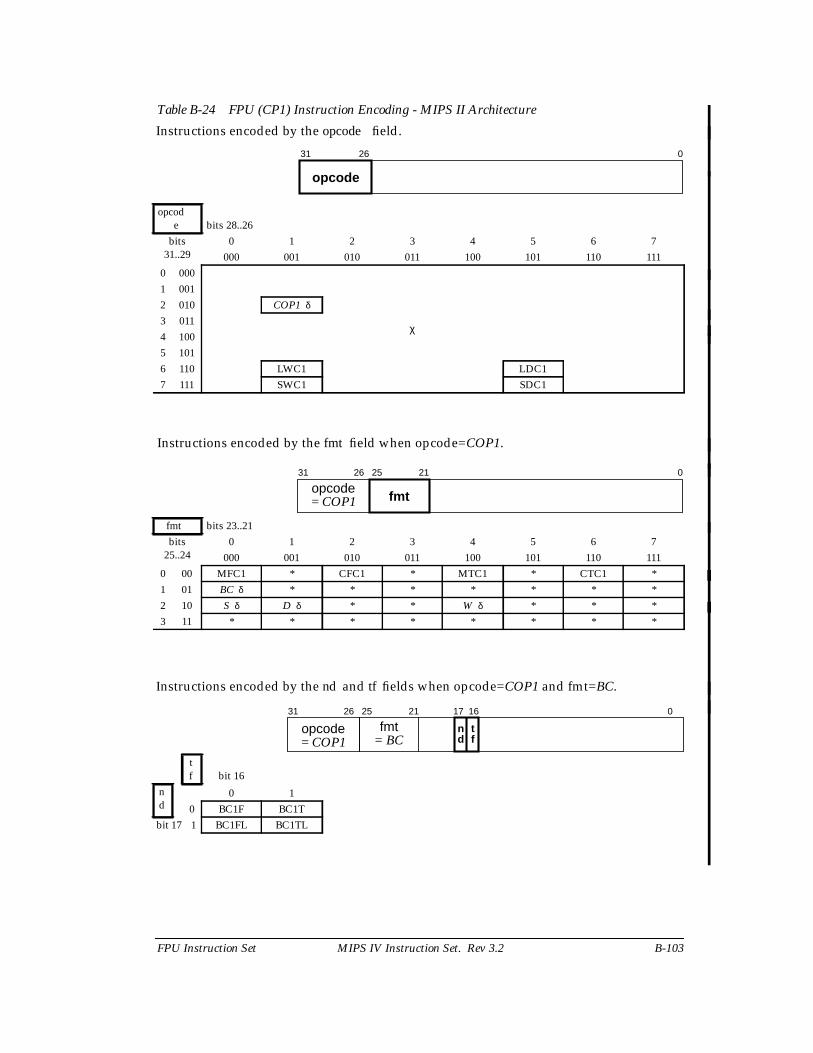
FPU Instruction Set MIPS IV Instruction Set. Rev 3.2 B-103
Table B-24 FPU (CP1) Instruction Encoding - MIPS II Architecture
Instructions encoded by the opcode field.
opcode bits 28..26
bits31..29
0 1 2 3 4 5 6 7000 001 010 011 100 101 110 111
0 000
χ
1 0012 010 COP1 δ
3 0114 1005 1016 110 LWC1 LDC17 111 SWC1 SDC1
Instructions encoded by the fmt field when opcode=COP1.
fmt bits 23..21bits
25..240 1 2 3 4 5 6 7
000 001 010 011 100 101 110 1110 00 MFC1 * CFC1 * MTC1 * CTC1 *1 01 BC δ * * * * * * *2 10 S δ D δ * * W δ * * *3 11 * * * * * * * *
Instructions encoded by the nd and tf fields when opcode=COP1 and fmt=BC.
tf bit 16
nd
0 10 BC1F BC1T
bit 17 1 BC1FL BC1TL
31 26
opcode
0
31 26
opcode 25 21
fmt
0
= COP1
31 26
opcode 25 21
fmt17 16
n td f
0
= BC= COP1
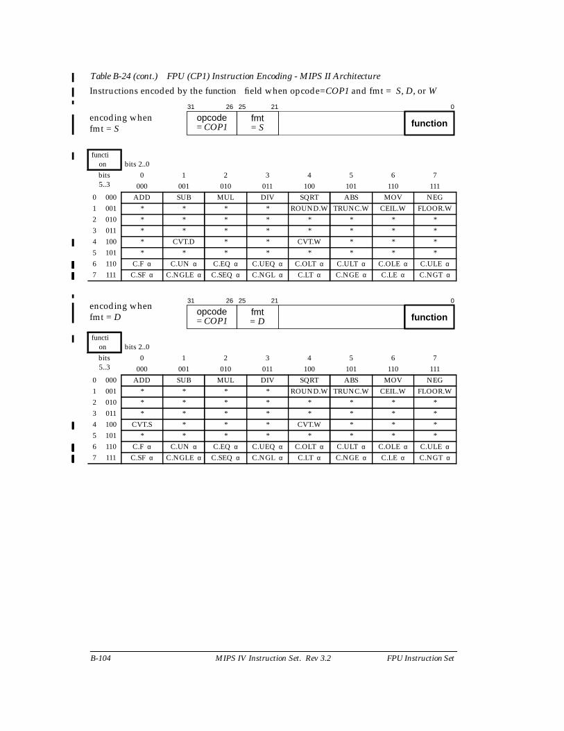
B-104 MIPS IV Instruction Set. Rev 3.2 FPU Instruction Set
Table B-24 (cont.) FPU (CP1) Instruction Encoding - MIPS II Architecture
Instructions encoded by the function field when opcode=COP1 and fmt = S, D, or W
encoding whenfmt = S
function bits 2..0bits5..3
0 1 2 3 4 5 6 7000 001 010 011 100 101 110 111
0 000 ADD SUB MUL DIV SQRT ABS MOV NEG1 001 * * * * ROUND.W TRUNC.W CEIL.W FLOOR.W2 010 * * * * * * * *3 011 * * * * * * * *4 100 * CVT.D * * CVT.W * * *5 101 * * * * * * * *6 110 C.F α C.UN α C.EQ α C.UEQ α C.OLT α C.ULT α C.OLE α C.ULE α
7 111 C.SF α C.NGLE α C.SEQ α C.NGL α C.LT α C.NGE α C.LE α C.NGT α
encoding whenfmt = D
function bits 2..0bits5..3
0 1 2 3 4 5 6 7000 001 010 011 100 101 110 111
0 000 ADD SUB MUL DIV SQRT ABS MOV NEG1 001 * * * * ROUND.W TRUNC.W CEIL.W FLOOR.W2 010 * * * * * * * *3 011 * * * * * * * *4 100 CVT.S * * * CVT.W * * *5 101 * * * * * * * *6 110 C.F α C.UN α C.EQ α C.UEQ α C.OLT α C.ULT α C.OLE α C.ULE α
7 111 C.SF α C.NGLE α C.SEQ α C.NGL α C.LT α C.NGE α C.LE α C.NGT α
31 26
opcode 25 21
fmt0
= COP1 = S function
31 26
opcode 25 21
fmt0
= COP1 = D function
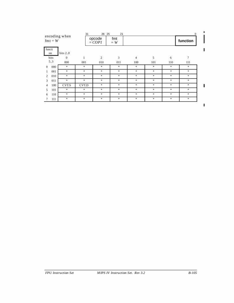
FPU Instruction Set MIPS IV Instruction Set. Rev 3.2 B-105
encoding whenfmt = W
function bits 2..0bits5..3
0 1 2 3 4 5 6 7000 001 010 011 100 101 110 111
0 000 * * * * * * * *1 001 * * * * * * * *2 010 * * * * * * * *3 011 * * * * * * * *4 100 CVT.S CVT.D * * * * * *5 101 * * * * * * * *6 110 * * * * * * * *7 111 * * * * * * * *
31 26
opcode 25 21
fmt0
= COP1 = W function
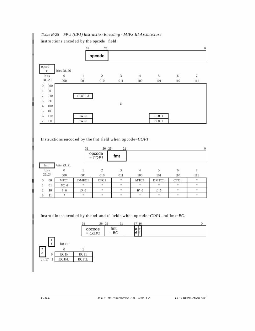
B-106 MIPS IV Instruction Set. Rev 3.2 FPU Instruction Set
Table B-25 FPU (CP1) Instruction Encoding - MIPS III Architecture
Instructions encoded by the opcode field.
opcode bits 28..26
bits31..29
0 1 2 3 4 5 6 7000 001 010 011 100 101 110 111
0 000
χ
1 0012 010 COP1 δ
3 0114 1005 1016 110 LWC1 LDC17 111 SWC1 SDC1
Instructions encoded by the fmt field when opcode=COP1.
fmt bits 23..21bits
25..240 1 2 3 4 5 6 7
000 001 010 011 100 101 110 1110 00 MFC1 DMFC1 CFC1 * MTC1 DMTC1 CTC1 *1 01 BC δ * * * * * * *2 10 S δ D δ * * W δ L δ * *3 11 * * * * * * * *
Instructions encoded by the nd and tf fields when opcode=COP1 and fmt=BC.
tf bit 16
nd
0 10 BC1F BC1T
bit 17 1 BC1FL BC1TL
31 26
opcode
0
31 26
opcode 25 21
fmt
0
= COP1
31 26
opcode 25 21
fmt17 16
n td f
0
= BC= COP1

FPU Instruction Set MIPS IV Instruction Set. Rev 3.2 B-107
Table B-25 (cont.) FPU (CP1) Instruction Encoding - MIPS III Architecture
Instructions encoded by the function field when opcode=COP1 and fmt = S, D, W, or L
encoding whenfmt = S
function bits 2..0bits5..3
0 1 2 3 4 5 6 7000 001 010 011 100 101 110 111
0 000 ADD SUB MUL DIV SQRT ABS MOV NEG1 001 ROUND.L TRUNC.L CEIL.L FLOOR.L ROUND.W TRUNC.W CEIL.W FLOOR.W2 010 * * * * * * *3 011 * * * * * * * *4 100 * CVT.D * * CVT.W CVT.L * *5 101 * * * * * * * *6 110 C.F α C.UN α C.EQ α C.UEQ α C.OLT α C.ULT α C.OLE α C.ULE α
7 111 C.SF α C.NGLE α C.SEQ α C.NGL α C.LT α C.NGE α C.LE α C.NGT α
encoding whenfmt = D
function bits 2..0bits5..3
0 1 2 3 4 5 6 7000 001 010 011 100 101 110 111
0 000 ADD SUB MUL DIV SQRT ABS MOV NEG1 001 ROUND.L TRUNC.L CEIL.L FLOOR.L ROUND.W TRUNC.W CEIL.W FLOOR.W2 010 * * * * * * *3 011 * * * * * * * *4 100 CVT.S * * * CVT.W CVT.L * *5 101 * * * * * * * *6 110 C.F α C.UN α C.EQ α C.UEQ α C.OLT α C.ULT α C.OLE α C.ULE α
7 111 C.SF α C.NGLE α C.SEQ α C.NGL α C.LT α C.NGE α C.LE α C.NGT α
31 26
opcode 25 21
fmt0
= COP1 = S function
31 26
opcode 25 21
fmt0
= COP1 = D function
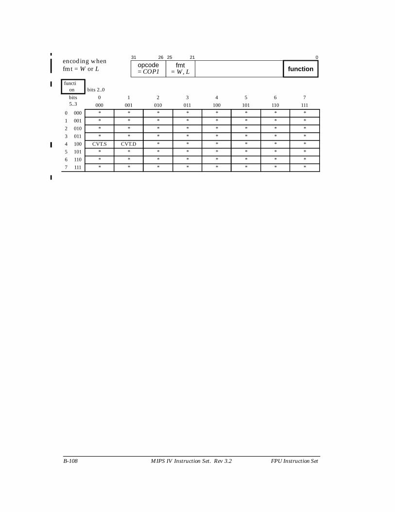
B-108 MIPS IV Instruction Set. Rev 3.2 FPU Instruction Set
encoding whenfmt = W or L
function bits 2..0bits5..3
0 1 2 3 4 5 6 7000 001 010 011 100 101 110 111
0 000 * * * * * * * *1 001 * * * * * * * *2 010 * * * * * * * *3 011 * * * * * * * *4 100 CVT.S CVT.D * * * * * *5 101 * * * * * * * *6 110 * * * * * * * *7 111 * * * * * * * *
31 26
opcode 25 21
fmt0
= COP1 = W, L function
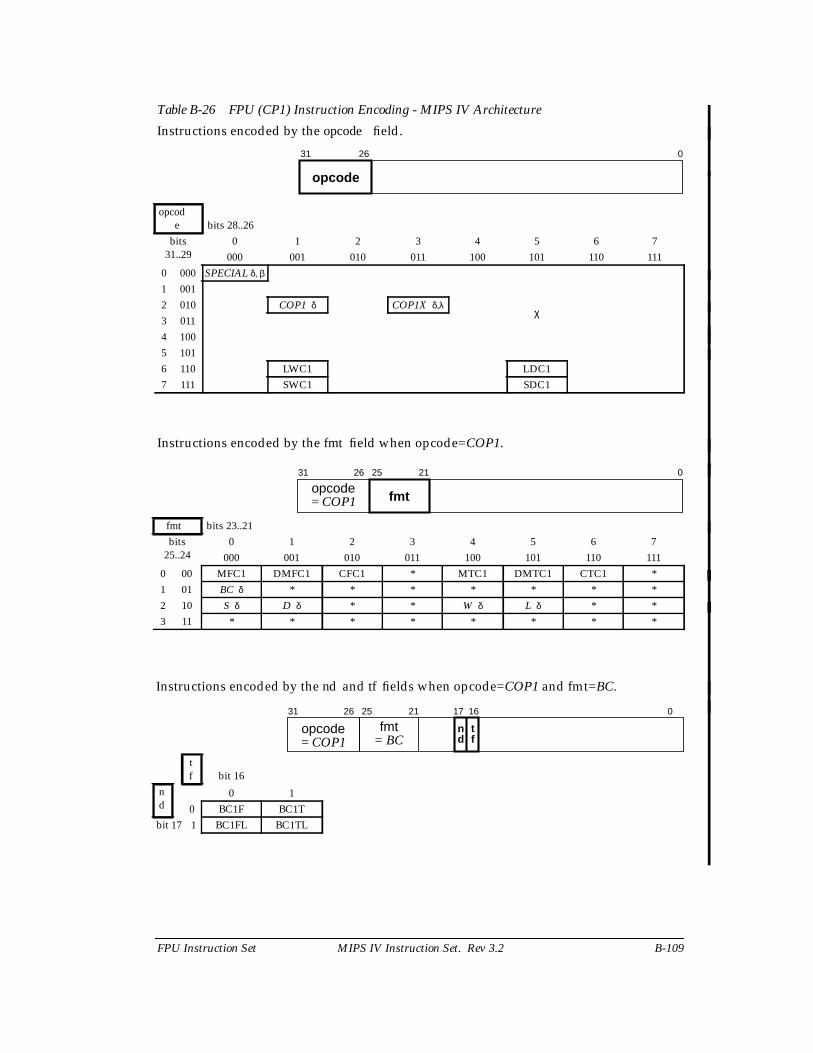
FPU Instruction Set MIPS IV Instruction Set. Rev 3.2 B-109
Table B-26 FPU (CP1) Instruction Encoding - MIPS IV Architecture
Instructions encoded by the opcode field.
opcode bits 28..26
bits31..29
0 1 2 3 4 5 6 7000 001 010 011 100 101 110 111
0 000 SPECIAL δ, β
χ
1 0012 010 COP1 δ COP1X δ,λ
3 0114 1005 1016 110 LWC1 LDC17 111 SWC1 SDC1
Instructions encoded by the fmt field when opcode=COP1.
fmt bits 23..21bits
25..240 1 2 3 4 5 6 7
000 001 010 011 100 101 110 1110 00 MFC1 DMFC1 CFC1 * MTC1 DMTC1 CTC1 *1 01 BC δ * * * * * * *2 10 S δ D δ * * W δ L δ * *3 11 * * * * * * * *
Instructions encoded by the nd and tf fields when opcode=COP1 and fmt=BC.
tf bit 16
nd
0 10 BC1F BC1T
bit 17 1 BC1FL BC1TL
31 26
opcode
0
31 26
opcode 25 21
fmt
0
= COP1
31 26
opcode 25 21
fmt17 16
n td f
0
= BC= COP1
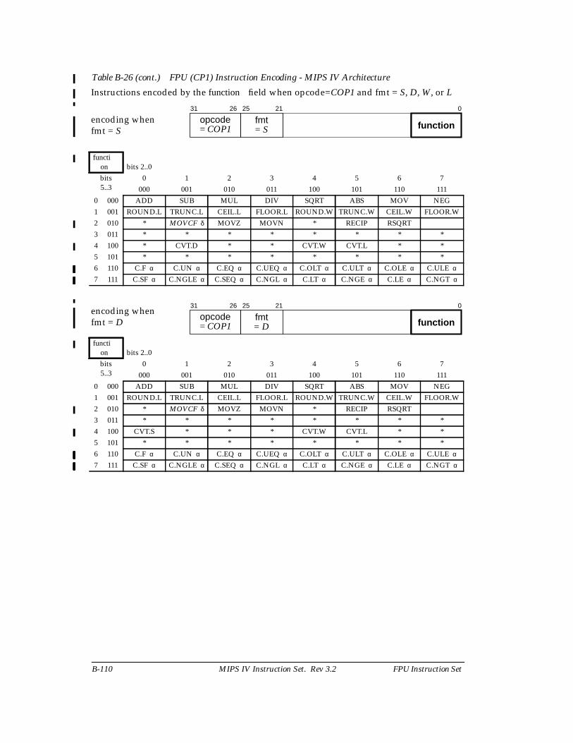
B-110 MIPS IV Instruction Set. Rev 3.2 FPU Instruction Set
Table B-26 (cont.) FPU (CP1) Instruction Encoding - MIPS IV Architecture
Instructions encoded by the function field when opcode=COP1 and fmt = S, D, W, or L
encoding whenfmt = S
function bits 2..0bits5..3
0 1 2 3 4 5 6 7000 001 010 011 100 101 110 111
0 000 ADD SUB MUL DIV SQRT ABS MOV NEG1 001 ROUND.L TRUNC.L CEIL.L FLOOR.L ROUND.W TRUNC.W CEIL.W FLOOR.W2 010 * MOVCF δ MOVZ MOVN * RECIP RSQRT3 011 * * * * * * * *4 100 * CVT.D * * CVT.W CVT.L * *5 101 * * * * * * * *6 110 C.F α C.UN α C.EQ α C.UEQ α C.OLT α C.ULT α C.OLE α C.ULE α
7 111 C.SF α C.NGLE α C.SEQ α C.NGL α C.LT α C.NGE α C.LE α C.NGT α
encoding whenfmt = D
function bits 2..0bits5..3
0 1 2 3 4 5 6 7000 001 010 011 100 101 110 111
0 000 ADD SUB MUL DIV SQRT ABS MOV NEG1 001 ROUND.L TRUNC.L CEIL.L FLOOR.L ROUND.W TRUNC.W CEIL.W FLOOR.W2 010 * MOVCF δ MOVZ MOVN * RECIP RSQRT3 011 * * * * * * * *4 100 CVT.S * * * CVT.W CVT.L * *5 101 * * * * * * * *6 110 C.F α C.UN α C.EQ α C.UEQ α C.OLT α C.ULT α C.OLE α C.ULE α
7 111 C.SF α C.NGLE α C.SEQ α C.NGL α C.LT α C.NGE α C.LE α C.NGT α
31 26
opcode 25 21
fmt0
= COP1 = S function
31 26
opcode 25 21
fmt0
= COP1 = D function
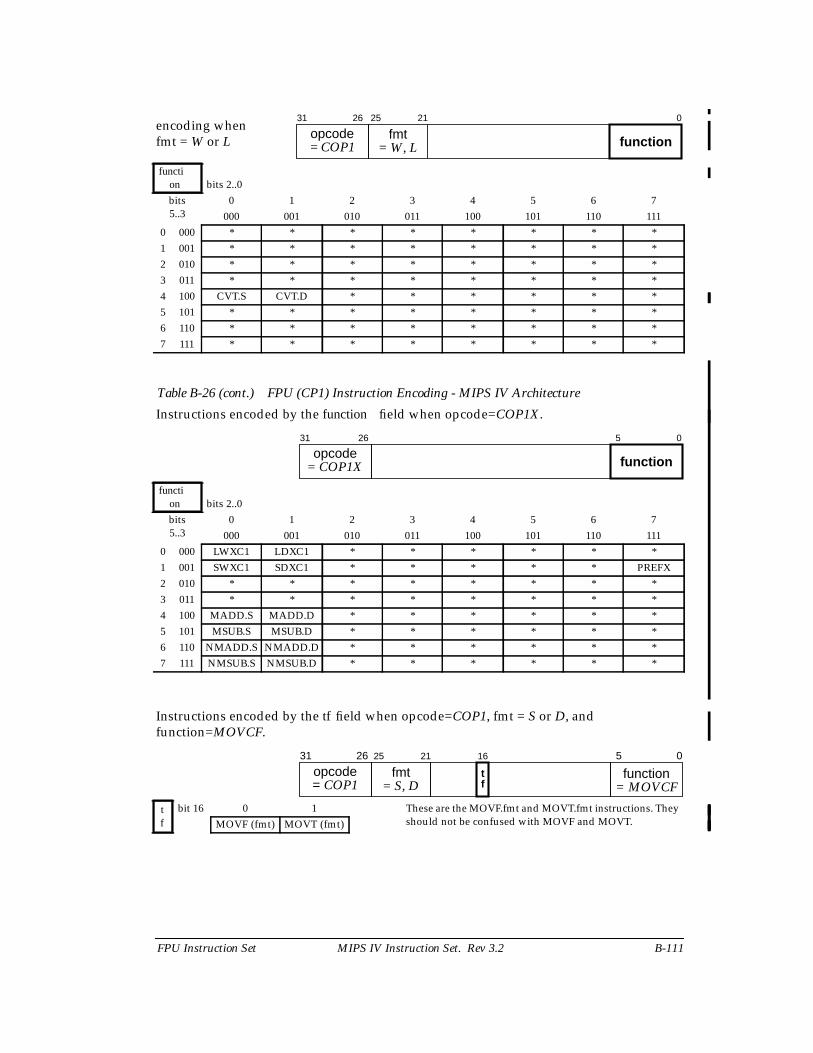
FPU Instruction Set MIPS IV Instruction Set. Rev 3.2 B-111
Table B-26 (cont.) FPU (CP1) Instruction Encoding - MIPS IV Architecture
encoding whenfmt = W or L
function bits 2..0bits5..3
0 1 2 3 4 5 6 7000 001 010 011 100 101 110 111
0 000 * * * * * * * *1 001 * * * * * * * *2 010 * * * * * * * *3 011 * * * * * * * *4 100 CVT.S CVT.D * * * * * *5 101 * * * * * * * *6 110 * * * * * * * *7 111 * * * * * * * *
Instructions encoded by the function field when opcode=COP1X.
function bits 2..0bits5..3
0 1 2 3 4 5 6 7000 001 010 011 100 101 110 111
0 000 LWXC1 LDXC1 * * * * * *1 001 SWXC1 SDXC1 * * * * * PREFX2 010 * * * * * * * *3 011 * * * * * * * *4 100 MADD.S MADD.D * * * * * *5 101 MSUB.S MSUB.D * * * * * *6 110 NMADD.S NMADD.D * * * * * *7 111 NMSUB.S NMSUB.D * * * * * *
Instructions encoded by the tf field when opcode=COP1, fmt = S or D, andfunction=MOVCF.
tf
bit 16 0 1 These are the MOVF.fmt and MOVT.fmt instructions. Theyshould not be confused with MOVF and MOVT.MOVF (fmt) MOVT (fmt)
31 26
opcode 25 21
fmt0
= COP1 = W, L function
31 26
opcodefunction
5 0
= COP1X
31 26
opcode function 5 0
= COP1 = MOVCF
16
tf
25 21
fmt= S, D
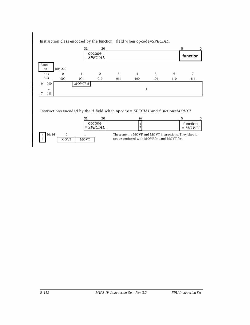
B-112 MIPS IV Instruction Set. Rev 3.2 FPU Instruction Set
Instruction class encoded by the function field when opcode=SPECIAL.
function bits 2..0bits5..3
0 1 2 3 4 5 6 7000 001 010 011 100 101 110 111
0 000 MOVCI δ
χ...7 111
Instructions encoded by the tf field when opcode = SPECIAL and function=MOVCI.
tf
bit 16 0 1 These are the MOVF and MOVT instructions. They shouldnot be confused with MOVF.fmt and MOVT.fmt.MOVF MOVT
31 26
opcodefunction
5 0
= SPECIAL
31 26
opcode function 5 0
= SPECIAL = MOVCI
16
tf
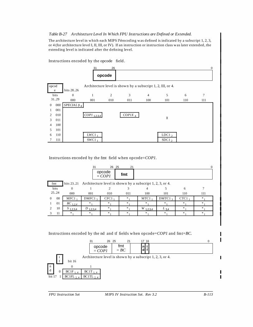
FPU Instruction Set MIPS IV Instruction Set. Rev 3.2 B-113
Table B-27 Architecture Level In Which FPU Instructions are Defined or Extended.
The architecture level in which each MIPS IVencoding was defined is indicated by a subscript 1, 2, 3,or 4 (for architecture level I, II, III, or IV). If an instruction or instruction class was later extended, theextending level is indicated after the defining level.
Instructions encoded by the opcode field.
opcode bits 28..26
Architecture level is shown by a subscript 1, 2, III, or 4.
bits31..29
0 1 2 3 4 5 6 7000 001 010 011 100 101 110 111
0 000 SPECIAL β 4
χ
1 0012 010 COP1 1,2,3,4 COP1X 4
3 0114 1005 1016 110 LWC1 1 LDC1 2
7 111 SWC1 1 SDC1 2
Instructions encoded by the fmt field when opcode=COP1.
fmt bits 23..21 Architecture level is shown by a subscript 1, 2, 3, or 4.bits
25..240 1 2 3 4 5 6 7
000 001 010 011 100 101 110 1110 00 MFC1 1 DMFC1 3 CFC1 1 * 1 MTC1 1 DMTC1 3 CTC1 1 * 1
1 01 BC 1,2,4 * 1 * 1 * 1 * 1 * 1 * 1 * 1
2 10 S 1,2,3,4 D 1,2,3,4 * 1 * 1 W 1,2,3,4 L 3,4 * 1 * 1
3 11 * 1 * 1 * 1 * 1 * 1 * 1 * 1 * 1
Instructions encoded by the nd and tf fields when opcode=COP1 and fmt=BC.
tf bit 16
Architecture level is shown by a subscript 1, 2, 3, or 4.
nd
0 10 BC1F 1, 4 BC1T 1, 4
bit 17 1 BC1FL 2, 4 BC1TL 2, 4
31 26
opcode
0
31 26
opcode 25 21
fmt
0
= COP1
31 26
opcode 25 21
fmt17 16
n td f
0
= BC= COP1
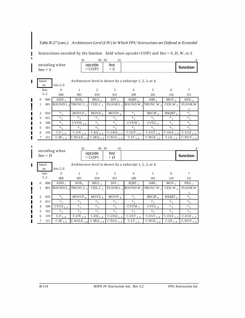
B-114 MIPS IV Instruction Set. Rev 3.2 FPU Instruction Set
Table B-27 (cont.) Architecture Level (I-IV) In Which FPU Instructions are Defined or Extended
Instructions encoded by the function field when opcode=COP1 and fmt = S, D, W, or L
encoding whenfmt = S
function bits 2..0
Architecture level is shown by a subscript 1, 2, 3, or 4.
bits5..3
0 1 2 3 4 5 6 7000 001 010 011 100 101 110 111
0 000 ADD 1 SUB 1 MUL 1 DIV 1 SQRT 2 ABS 1 MOV 1 NEG 1
1 001 ROUND.L 3 TRUNC.L 3 CEIL.L 3 FLOOR.L 3 ROUND.W 2 TRUNC.W 2 CEIL.W 2 FLOOR.W2
2 010 * 1 MOVCF 4 MOVZ 4 MOVN 4 * 1 RECIP 4 RSQRT 4 * 1
3 011 * 1 * 1 * 1 * 1 * 1 * 1 * 1 * 1
4 100 * 1 CVT.D 1, 3 * 1 * 1 CVT.W 1 CVT.L 3 * 1 * 1
5 101 * 1 * 1 * 1 * 1 * 1 * 1 * 1 * 1
6 110 C.F 1, 4 C.UN 1, 4 C.EQ 1, 4 C.UEQ 1, 4 C.OLT 1, 4 C.ULT 1, 4 C.OLE 1, 4 C.ULE 1, 4
7 111 C.SF 1, 4 C.NGLE 1, 4 C.SEQ 1, 4 C.NGL 1, 4 C.LT 1, 4 C.NGE 1, 4 C.LE 1, 4 C.NGT 1, 4
encoding whenfmt = D
function bits 2..0
Architecture level is shown by a subscript 1, 2, 3, or 4.
bits5..3
0 1 2 3 4 5 6 7000 001 010 011 100 101 110 111
0 000 ADD 1 SUB 1 MUL 1 DIV 1 SQRT 2 ABS 1 MOV 1 NEG 1
1 001 ROUND.L 3 TRUNC.L 3 CEIL.L 3 FLOOR.L 3 ROUND.W 2 TRUNC.W 2 CEIL.W 2 FLOOR.W2
2 010 * 1 MOVCF 4 MOVZ 4 MOVN 4 * 1 RECIP 4 RSQRT 4 * 1
3 011 * 1 * 1 * 1 * 1 * 1 * 1 * 1 * 1
4 100 CVT.S 1, 3 * 1 * 1 * 1 CVT.W 1 CVT.L 3 * 1 * 1
5 101 * 1 * 1 * 1 * 1 * 1 * 1 * 1 * 1
6 110 C.F 1, 4 C.UN 1, 4 C.EQ 1, 4 C.UEQ 1, 4 C.OLT 1, 4 C.ULT 1, 4 C.OLE 1, 4 C.ULE 1, 4
7 111 C.SF 1, 4 C.NGLE 1, 4 C.SEQ 1, 4 C.NGL 1, 4 C.LT 1, 4 C.NGE 1, 4 C.LE 1, 4 C.NGT 1, 4
31 26
opcode 25 21
fmt0
= COP1 = S function
31 26
opcode 25 21
fmt0
= COP1 = D function
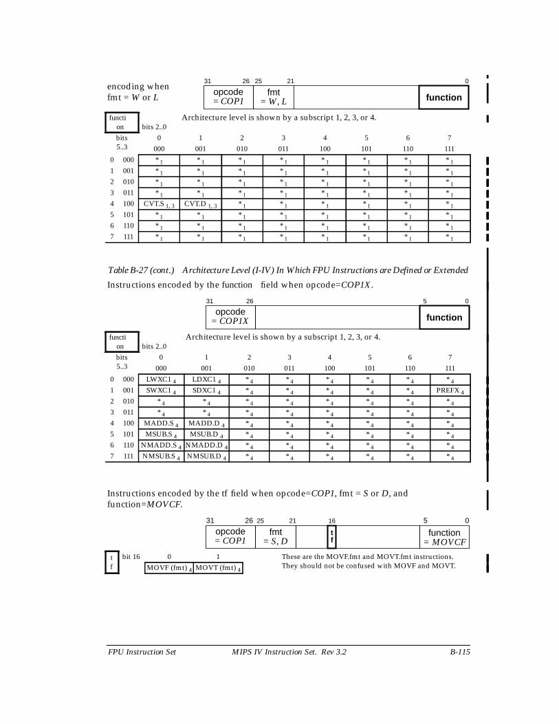
FPU Instruction Set MIPS IV Instruction Set. Rev 3.2 B-115
Table B-27 (cont.) Architecture Level (I-IV) In Which FPU Instructions are Defined or Extended
encoding whenfmt = W or L
function bits 2..0
Architecture level is shown by a subscript 1, 2, 3, or 4.
bits5..3
0 1 2 3 4 5 6 7000 001 010 011 100 101 110 111
0 000 * 1 * 1 * 1 * 1 * 1 * 1 * 1 * 1
1 001 * 1 * 1 * 1 * 1 * 1 * 1 * 1 * 1
2 010 * 1 * 1 * 1 * 1 * 1 * 1 * 1 * 1
3 011 * 1 * 1 * 1 * 1 * 1 * 1 * 1 * 1
4 100 CVT.S 1, 3 CVT.D 1, 3 * 1 * 1 * 1 * 1 * 1 * 1
5 101 * 1 * 1 * 1 * 1 * 1 * 1 * 1 * 1
6 110 * 1 * 1 * 1 * 1 * 1 * 1 * 1 * 1
7 111 * 1 * 1 * 1 * 1 * 1 * 1 * 1 * 1
Instructions encoded by the function field when opcode=COP1X.
function bits 2..0
Architecture level is shown by a subscript 1, 2, 3, or 4.
bits5..3
0 1 2 3 4 5 6 7000 001 010 011 100 101 110 111
0 000 LWXC1 4 LDXC1 4 * 4 * 4 * 4 * 4 * 4 * 4
1 001 SWXC1 4 SDXC1 4 * 4 * 4 * 4 * 4 * 4 PREFX 4
2 010 * 4 * 4 * 4 * 4 * 4 * 4 * 4 * 4
3 011 * 4 * 4 * 4 * 4 * 4 * 4 * 4 * 4
4 100 MADD.S 4 MADD.D 4 * 4 * 4 * 4 * 4 * 4 * 4
5 101 MSUB.S 4 MSUB.D 4 * 4 * 4 * 4 * 4 * 4 * 4
6 110 NMADD.S 4 NMADD.D 4 * 4 * 4 * 4 * 4 * 4 * 4
7 111 NMSUB.S 4 NMSUB.D 4 * 4 * 4 * 4 * 4 * 4 * 4
Instructions encoded by the tf field when opcode=COP1, fmt = S or D, andfunction=MOVCF.
tf
bit 16 0 1 These are the MOVF.fmt and MOVT.fmt instructions.They should not be confused with MOVF and MOVT.MOVF (fmt) 4 MOVT (fmt) 4
31 26
opcode 25 21
fmt0
= COP1 = W, L function
31 26
opcodefunction
5 0
= COP1X
31 26
opcode function 5 0
= COP1 = MOVCF
16
tf
25 21
fmt= S, D
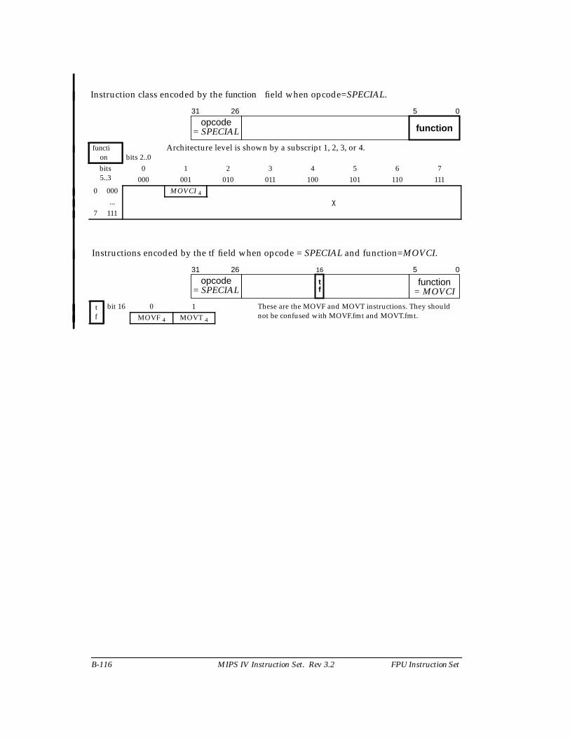
B-116 MIPS IV Instruction Set. Rev 3.2 FPU Instruction Set
Instruction class encoded by the function field when opcode=SPECIAL.
function bits 2..0
Architecture level is shown by a subscript 1, 2, 3, or 4.
bits5..3
0 1 2 3 4 5 6 7000 001 010 011 100 101 110 111
0 000 MOVCI 4
χ...7 111
Instructions encoded by the tf field when opcode = SPECIAL and function=MOVCI.
tf
bit 16 0 1 These are the MOVF and MOVT instructions. They shouldnot be confused with MOVF.fmt and MOVT.fmt.MOVF 4 MOVT 4
31 26
opcodefunction
5 0
= SPECIAL
31 26
opcode function 5 0
= SPECIAL = MOVCI
16
tf
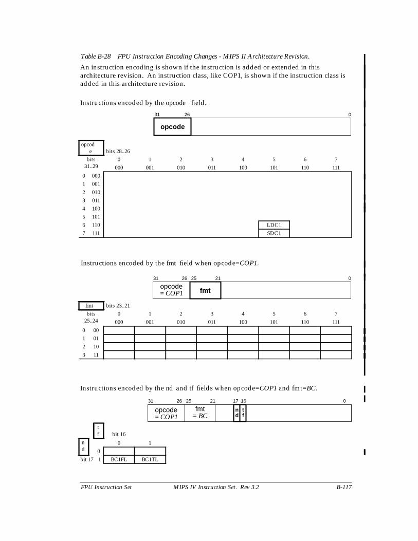
FPU Instruction Set MIPS IV Instruction Set. Rev 3.2 B-117
Table B-28 FPU Instruction Encoding Changes - MIPS II Architecture Revision.
An instruction encoding is shown if the instruction is added or extended in thisarchitecture revision. An instruction class, like COP1, is shown if the instruction class isadded in this architecture revision.
Instructions encoded by the opcode field.
opcode bits 28..26
bits31..29
0 1 2 3 4 5 6 7000 001 010 011 100 101 110 111
0 0001 0012 0103 0114 1005 1016 110 LDC17 111 SDC1
Instructions encoded by the fmt field when opcode=COP1.
fmt bits 23..21bits
25..240 1 2 3 4 5 6 7
000 001 010 011 100 101 110 1110 001 012 103 11
Instructions encoded by the nd and tf fields when opcode=COP1 and fmt=BC.
tf bit 16
nd
0 10
bit 17 1 BC1FL BC1TL
31 26
opcode
0
31 26
opcode 25 21
fmt
0
= COP1
31 26
opcode 25 21
fmt17 16
n td f
0
= BC= COP1
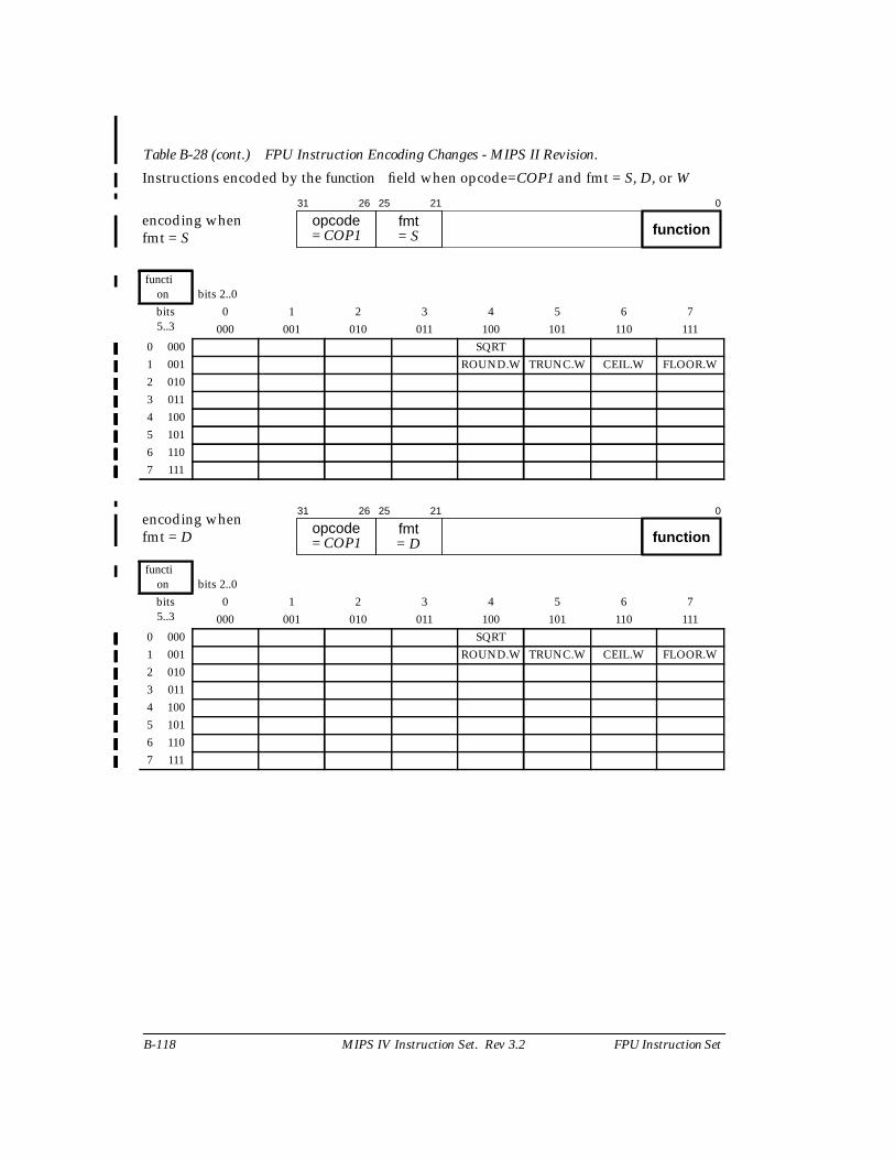
B-118 MIPS IV Instruction Set. Rev 3.2 FPU Instruction Set
Table B-28 (cont.) FPU Instruction Encoding Changes - MIPS II Revision.
Instructions encoded by the function field when opcode=COP1 and fmt = S, D, or W
encoding whenfmt = S
function bits 2..0bits5..3
0 1 2 3 4 5 6 7000 001 010 011 100 101 110 111
0 000 SQRT1 001 ROUND.W TRUNC.W CEIL.W FLOOR.W2 0103 0114 1005 1016 1107 111
encoding whenfmt = D
function bits 2..0bits5..3
0 1 2 3 4 5 6 7000 001 010 011 100 101 110 111
0 000 SQRT1 001 ROUND.W TRUNC.W CEIL.W FLOOR.W2 0103 0114 1005 1016 1107 111
31 26
opcode 25 21
fmt0
= COP1 = S function
31 26
opcode 25 21
fmt0
= COP1 = D function
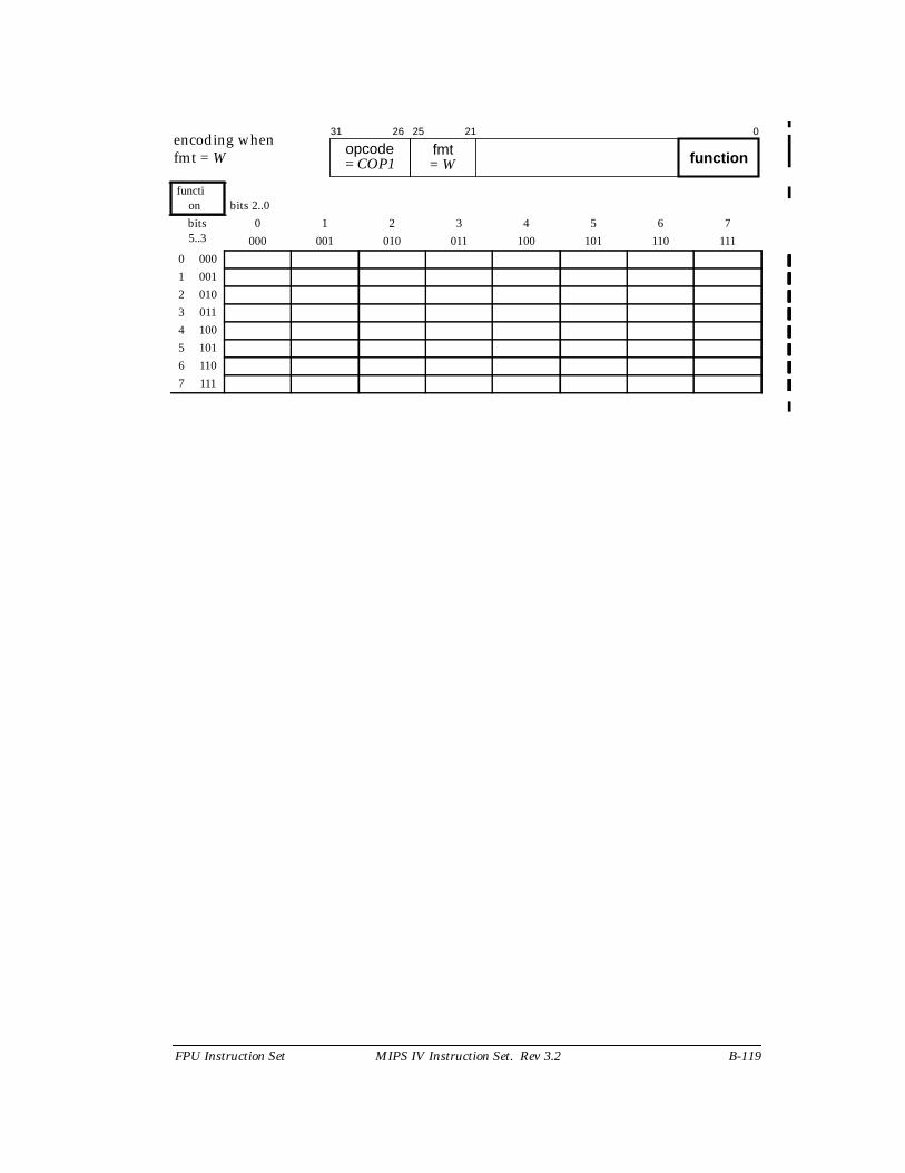
FPU Instruction Set MIPS IV Instruction Set. Rev 3.2 B-119
encoding whenfmt = W
function bits 2..0bits5..3
0 1 2 3 4 5 6 7000 001 010 011 100 101 110 111
0 0001 0012 0103 0114 1005 1016 1107 111
31 26
opcode 25 21
fmt0
= COP1 = W function
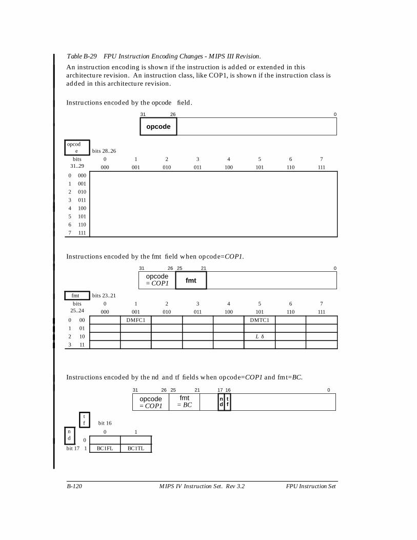
B-120 MIPS IV Instruction Set. Rev 3.2 FPU Instruction Set
Table B-29 FPU Instruction Encoding Changes - MIPS III Revision.
An instruction encoding is shown if the instruction is added or extended in thisarchitecture revision. An instruction class, like COP1, is shown if the instruction class isadded in this architecture revision.
Instructions encoded by the opcode field.
opcode bits 28..26
bits31..29
0 1 2 3 4 5 6 7000 001 010 011 100 101 110 111
0 0001 0012 0103 0114 1005 1016 1107 111
Instructions encoded by the fmt field when opcode=COP1.
fmt bits 23..21bits
25..240 1 2 3 4 5 6 7
000 001 010 011 100 101 110 1110 00 DMFC1 DMTC11 012 10 L δ
3 11
Instructions encoded by the nd and tf fields when opcode=COP1 and fmt=BC.
tf bit 16
nd
0 10
bit 17 1 BC1FL BC1TL
31 26
opcode
0
31 26
opcode 25 21
fmt
0
= COP1
31 26
opcode 25 21
fmt17 16
n td f
0
= BC= COP1
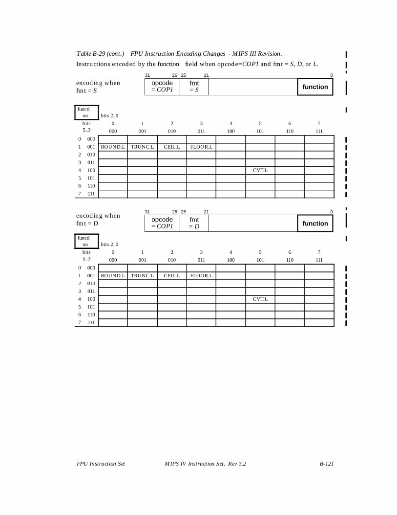
FPU Instruction Set MIPS IV Instruction Set. Rev 3.2 B-121
Table B-29 (cont.) FPU Instruction Encoding Changes - MIPS III Revision.
Instructions encoded by the function field when opcode=COP1 and fmt = S, D, or L.
encoding whenfmt = S
function bits 2..0bits5..3
0 1 2 3 4 5 6 7000 001 010 011 100 101 110 111
0 0001 001 ROUND.L TRUNC.L CEIL.L FLOOR.L2 0103 0114 100 CVT.L5 1016 1107 111
encoding whenfmt = D
function bits 2..0bits5..3
0 1 2 3 4 5 6 7000 001 010 011 100 101 110 111
0 0001 001 ROUND.L TRUNC.L CEIL.L FLOOR.L2 0103 0114 100 CVT.L5 1016 1107 111
31 26
opcode 25 21
fmt0
= COP1 = S function
31 26
opcode 25 21
fmt0
= COP1 = D function

B-122 MIPS IV Instruction Set. Rev 3.2 FPU Instruction Set
encoding whenfmt = L
function bits 2..0bits5..3
0 1 2 3 4 5 6 7000 001 010 011 100 101 110 111
0 000 * * * * * * * *1 001 * * * * * * * *2 010 * * * * * * * *3 011 * * * * * * * *4 100 CVT.S CVT.D * * * * * *5 101 * * * * * * * *6 110 * * * * * * * *7 111 * * * * * * * *
31 26
opcode 25 21
fmt0
= COP1 = L function
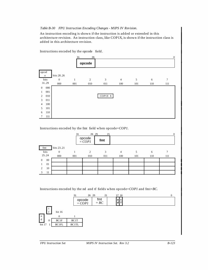
FPU Instruction Set MIPS IV Instruction Set. Rev 3.2 B-123
Table B-30 FPU Instruction Encoding Changes - MIPS IV Revision.
An instruction encoding is shown if the instruction is added or extended in thisarchitecture revision. An instruction class, like COP1X, is shown if the instruction class isadded in this architecture revision.
Instructions encoded by the opcode field.
opcode bits 28..26
bits31..29
0 1 2 3 4 5 6 7000 001 010 011 100 101 110 111
0 0001 0012 010 COP1X δ
3 0114 1005 1016 1107 111
Instructions encoded by the fmt field when opcode=COP1.
fmt bits 23..21bits
25..240 1 2 3 4 5 6 7
000 001 010 011 100 101 110 1110 001 012 103 11
Instructions encoded by the nd and tf fields when opcode=COP1 and fmt=BC.
tf bit 16
nd
0 10 BC1F BC1T
bit 17 1 BC1FL BC1TL
31 26
opcode
0
31 26
opcode 25 21
fmt
0
= COP1
31 26
opcode 25 21
fmt17 16
n td f
0
= BC= COP1
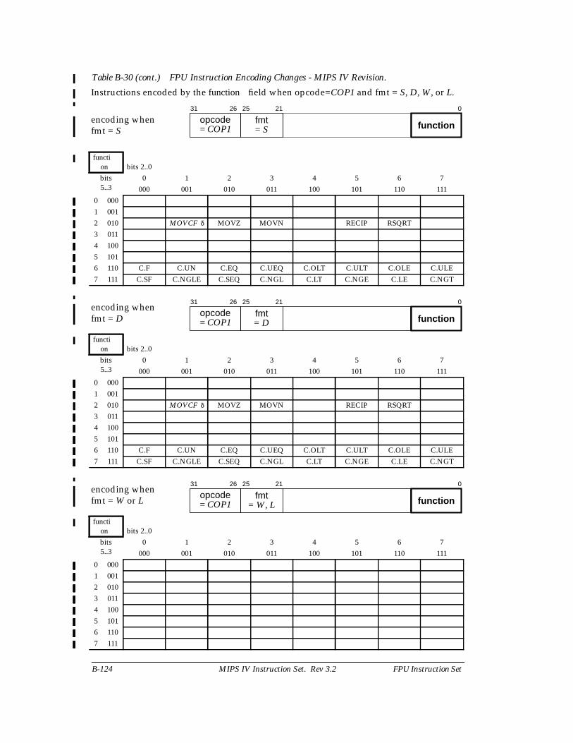
B-124 MIPS IV Instruction Set. Rev 3.2 FPU Instruction Set
Table B-30 (cont.) FPU Instruction Encoding Changes - MIPS IV Revision.
Instructions encoded by the function field when opcode=COP1 and fmt = S, D, W, or L.
encoding whenfmt = S
function bits 2..0bits5..3
0 1 2 3 4 5 6 7000 001 010 011 100 101 110 111
0 0001 0012 010 MOVCF δ MOVZ MOVN RECIP RSQRT3 0114 1005 1016 110 C.F C.UN C.EQ C.UEQ C.OLT C.ULT C.OLE C.ULE7 111 C.SF C.NGLE C.SEQ C.NGL C.LT C.NGE C.LE C.NGT
encoding whenfmt = D
function bits 2..0bits5..3
0 1 2 3 4 5 6 7000 001 010 011 100 101 110 111
0 0001 0012 010 MOVCF δ MOVZ MOVN RECIP RSQRT3 0114 1005 1016 110 C.F C.UN C.EQ C.UEQ C.OLT C.ULT C.OLE C.ULE7 111 C.SF C.NGLE C.SEQ C.NGL C.LT C.NGE C.LE C.NGT
encoding whenfmt = W or L
function bits 2..0bits5..3
0 1 2 3 4 5 6 7000 001 010 011 100 101 110 111
0 0001 0012 0103 0114 1005 1016 1107 111
31 26
opcode 25 21
fmt0
= COP1 = S function
31 26
opcode 25 21
fmt0
= COP1 = D function
31 26
opcode 25 21
fmt0
= COP1 = W, L function
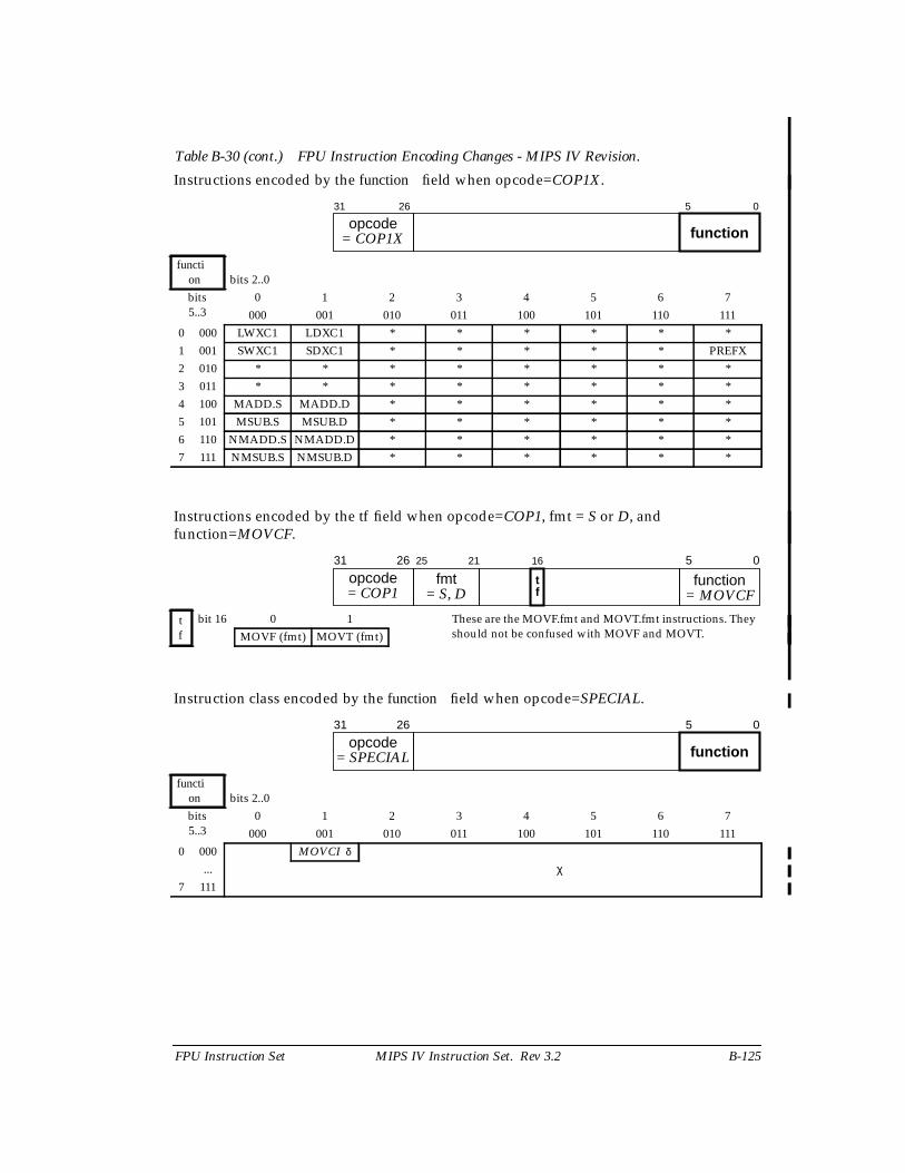
FPU Instruction Set MIPS IV Instruction Set. Rev 3.2 B-125
Table B-30 (cont.) FPU Instruction Encoding Changes - MIPS IV Revision.
Instructions encoded by the function field when opcode=COP1X.
function bits 2..0bits5..3
0 1 2 3 4 5 6 7000 001 010 011 100 101 110 111
0 000 LWXC1 LDXC1 * * * * * *1 001 SWXC1 SDXC1 * * * * * PREFX2 010 * * * * * * * *3 011 * * * * * * * *4 100 MADD.S MADD.D * * * * * *5 101 MSUB.S MSUB.D * * * * * *6 110 NMADD.S NMADD.D * * * * * *7 111 NMSUB.S NMSUB.D * * * * * *
Instructions encoded by the tf field when opcode=COP1, fmt = S or D, andfunction=MOVCF.
tf
bit 16 0 1 These are the MOVF.fmt and MOVT.fmt instructions. Theyshould not be confused with MOVF and MOVT.MOVF (fmt) MOVT (fmt)
Instruction class encoded by the function field when opcode=SPECIAL.
function bits 2..0bits5..3
0 1 2 3 4 5 6 7000 001 010 011 100 101 110 111
0 000 MOVCI δ
χ...7 111
31 26
opcodefunction
5 0
= COP1X
31 26
opcode function 5 0
= COP1 = MOVCF
16
tf
25 21
fmt= S, D
31 26
opcodefunction
5 0
= SPECIAL
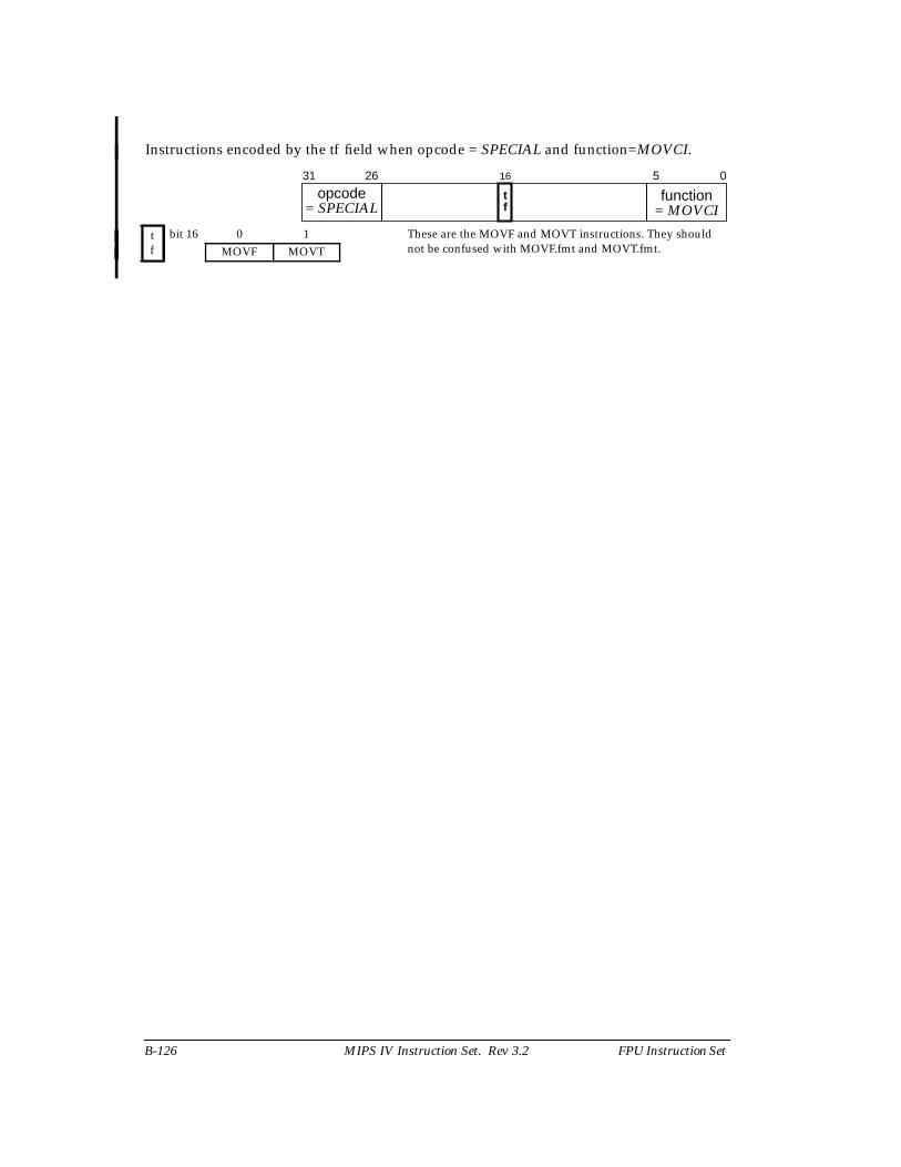
B-126 MIPS IV Instruction Set. Rev 3.2 FPU Instruction Set
Instructions encoded by the tf field when opcode = SPECIAL and function=MOVCI.
tf
bit 16 0 1 These are the MOVF and MOVT instructions. They shouldnot be confused with MOVF.fmt and MOVT.fmt.MOVF MOVT
31 26
opcode function 5 0
= SPECIAL = MOVCI
16
tf
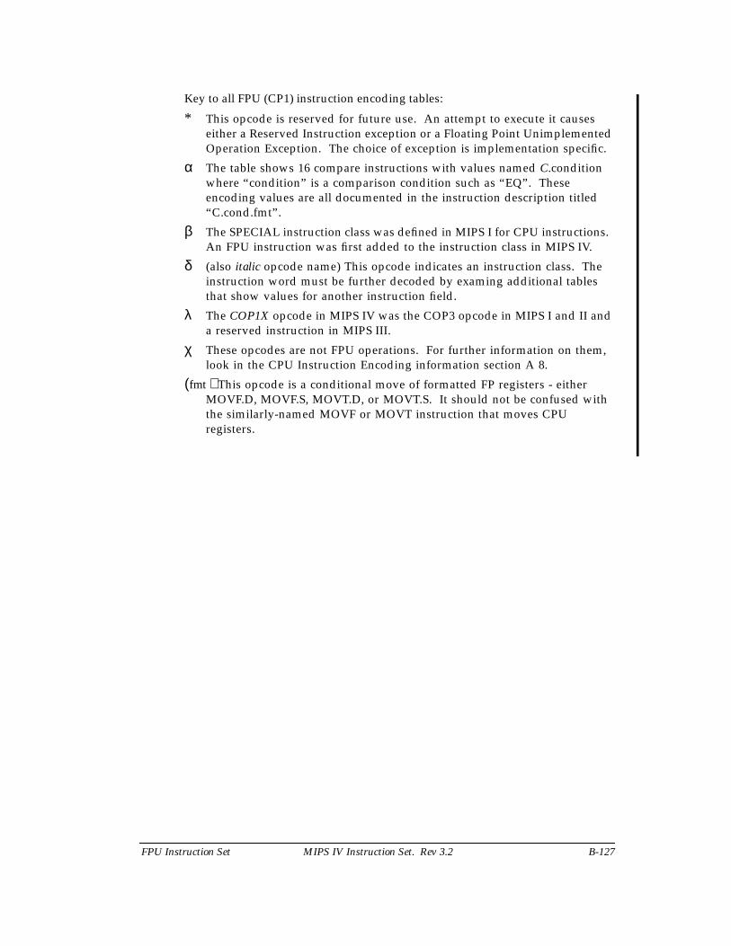
FPU Instruction Set MIPS IV Instruction Set. Rev 3.2 B-127
Key to all FPU (CP1) instruction encoding tables:
* This opcode is reserved for future use. An attempt to execute it causeseither a Reserved Instruction exception or a Floating Point UnimplementedOperation Exception. The choice of exception is implementation specific.
α The table shows 16 compare instructions with values named C.conditionwhere “condition” is a comparison condition such as “EQ”. Theseencoding values are all documented in the instruction description titled“C.cond.fmt”.
β The SPECIAL instruction class was defined in MIPS I for CPU instructions.An FPU instruction was first added to the instruction class in MIPS IV.
δ (also italic opcode name) This opcode indicates an instruction class. Theinstruction word must be further decoded by examing additional tablesthat show values for another instruction field.
λ The COP1X opcode in MIPS IV was the COP3 opcode in MIPS I and II anda reserved instruction in MIPS III.
χ These opcodes are not FPU operations. For further information on them,look in the CPU Instruction Encoding information section A 8.
(fmt ) This opcode is a conditional move of formatted FP registers - eitherMOVF.D, MOVF.S, MOVT.D, or MOVT.S. It should not be confused withthe similarly-named MOVF or MOVT instruction that moves CPUregisters.