HFSS 12.0 Tips and Techniques for HFSS Project Setup and Solve
International Research Journal of Engineering and Technology (IRJET) e-ISSN: 2395 -0056
Volume: 04 Issue: 04 | Apr -2017 www.irjet.net p-ISSN: 2395-0072
© 2017, IRJET | Impact Factor value: 5.181 | ISO 9001:2008 Certified Journal | Page 917
Miniaturization of Microstrip Patch Antenna for Mobile Application
Amit Rakholiya1, prof. Namrata Langhnoja2, Akash Dungrani3
1P.G. student, Department of Communication System Engineering, L.D.C.E., Ahmedabad, Gujarat, India 2Professor, Department of Communication System Engineering, L.D.C.E., Ahmedabad, Gujarat, India
3P.G. student, Department of Communication System Engineering, L.D.C.E., Ahmedabad, Gujarat, India
---------------------------------------------------------------------***---------------------------------------------------------------------
Abstract – Fractal Geometry property is used in this paper for the miniaturization of microstrip patch antenna. The unique space filling property of fractals is used to develop novel patch antenna at 1.575 GHz (L1 band) with significant reduced size than its conventional antenna. An inset fed antenna is taken as conventional base antenna. The fractal iteration of Sierpinski carpet in modified form is performed up to 3rd iteration. The antennas are designed using FEM (finite element method) HFSS 13.0 and Return Loss, Radiation Pattern, antenna gain and VSWR are demonstrated. Simulation results of Sierpinski carpet iterations and their comparison with the conventional base antenna shows size reduction of 31% in to 3rd iteration, without affecting antenna performances such as Return Loss, Impedance bandwidth and impedance matching. Key Words: Fractal antenna, inset-fed, Sierpinski carpet, Miniaturization, Microstrip patch antenna
1. INTRODUCTION Microstrip patch antenna (MPA) has become an integral part of wireless communication system because of their advantages such as low profile, light weight, available with planner and non-planner structure, simple and economical to manufacturer using modern printed circuit technology and integration with feed networks become easy. The increasing growth of wireless system requires miniaturized antenna. The conventional dimensions of MPA are around half wavelength and therefor, several miniaturization techniques are emerging to reduce these dimensions. The effective techniques to miniature antenna size are: use of high permittivity substrate [1], use of magnetic substrate [2], and increase in electrical length [3], and using shorting pins between patch and ground plane. Apart from these techniques and unlike Euclidean geometry is introduced in antenna designing for size reduction of patch antenna.
The term fractal (broken or irregular segments) was originally introduced by French mathematician Mandelbrot. The complexity of nature is captured by fractals than Euclidean geometry. Fractals are made from multiple iterations of a single geometrical shape. The fundamental
building blocks are scaled version of fractal shape. The application of fractals are such as image compression algorithm, whether prediction, integrated circuits, filter design and many more. Fractal electrodynamics is one of the major applications in which fractal geometry is combined with electromagnetic theory to explore radiation, propagation and scattering problems.
From the different characteristics of the fractal, space filling property is the most important to design an antenna. Different scaled versions of the same copy can be understand by self-similarity and self-affinity property of fractals. Image is reduced by same factor in all directions in self-similarity while self-affinity has different scale factor in different directions. Another important property of fractals is space filling which makes electrically longer them in compact space [4]. It has been observed that self-similar or self-affine property of fractals is useful to design multiband frequency antenna and space-filling property of fractals is useful to design small antenna such as Sierpinski carpet.
Fractal antennas can be designed in many different shapes like Sierpinski carpet, Sierpinski gasket, Minkowski loop and Koch island etc. various design shapes have been used to reduced size of antenna by using fractals on the patch antenna. Koch shaped fractal is used on the patch surface with RO4003 substrate to reduce size of antenna. A small size microstrip patch antenna is proposed by inserting Sierpinski carpet into a single patch and etching inner and outer edge according to Koch curve. The Koch island fractal boundary microstrip antenna has been numerically and experimentally analysed in to obtain considerable area reduction. The proposed antenna presents the application of fractal geometry to conventional antenna for optimization of its shape to reduce overall size of antenna. By using inset fed patch better impedance matching can be achieved. A simple space-filling fractal, modified Sierpinski carpet [5] with different iterations is etched on inset fed patch antenna to reduce the size than conventional antenna. .
2. ANTENNA DESIGN It is biggest challenge to antenna designers to make antenna with compact size and low cost with simple radiating element, good performance and easy fabrication which demands of today’s wireless systems. A modified Sierpinski
International Research Journal of Engineering and Technology (IRJET) e-ISSN: 2395 -0056
Volume: 04 Issue: 04 | Apr -2017 www.irjet.net p-ISSN: 2395-0072
© 2017, IRJET | Impact Factor value: 5.181 | ISO 9001:2008 Certified Journal | Page 918
carpet patch antenna with inset fed is designed to obtain these results.
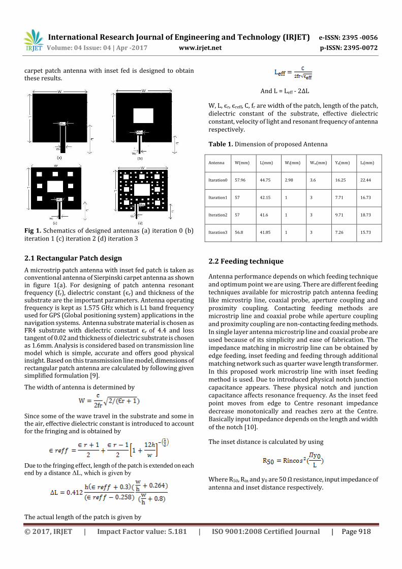
Fig 1. Schematics of designed antennas (a) iteration 0 (b) iteration 1 (c) iteration 2 (d) iteration 3
2.1 Rectangular Patch design
A microstrip patch antenna with inset fed patch is taken as conventional antenna of Sierpinski carpet antenna as shown in figure 1(a). For designing of patch antenna resonant frequency (fr), dielectric constant (єr) and thickness of the substrate are the important parameters. Antenna operating frequency is kept as 1.575 GHz which is L1 band frequency used for GPS (Global positioning system) applications in the navigation systems. Antenna substrate material is chosen as FR4 substrate with dielectric constant єr of 4.4 and loss tangent of 0.02 and thickness of dielectric substrate is chosen as 1.6mm. Analysis is considered based on transmission line model which is simple, accurate and offers good physical insight. Based on this transmission line model, dimensions of rectangular patch antenna are calculated by following given simplified formulation [9].
The width of antenna is determined by
Since some of the wave travel in the substrate and some in the air, effective dielectric constant is introduced to account for the fringing and is obtained by
Due to the fringing effect, length of the patch is extended on each end by a distance ΔL, which is given by
The actual length of the patch is given by
And L = Leff - 2ΔL
W, L, єr, єreff, C, fr are width of the patch, length of the patch, dielectric constant of the substrate, effective dielectric constant, velocity of light and resonant frequency of antenna respectively.
Table 1. Dimension of proposed Antenna
Antenna
W(mm)
L(mm)
Wf(mm)
Win(mm)
Y0(mm)
Lf(mm)
Itaration0
57.96
44.75
2.98
3.6
16.25
22.44
Itaration1
57
42.15
1
3
7.71
16.73
Iteration2
57
41.6
1
3
9.71
18.73
Itaration3
56.8
41.85
1
3
7.26
15.73
2.2 Feeding technique
Antenna performance depends on which feeding technique and optimum point we are using. There are different feeding techniques available for microstrip patch antenna feeding like microstrip line, coaxial probe, aperture coupling and proximity coupling. Contacting feeding methods are microstrip line and coaxial probe while aperture coupling and proximity coupling are non-contacting feeding methods. In single layer antenna microstrip line and coaxial probe are used because of its simplicity and ease of fabrication. The impedance matching in microstrip line can be obtained by edge feeding, inset feeding and feeding through additional matching network such as quarter wave length transformer. In this proposed work microstrip line with inset feeding method is used. Due to introduced physical notch junction capacitance appears. These physical notch and junction capacitance affects resonance frequency. As the inset feed point moves from edge to Centre resonant impedance decrease monotonically and reaches zero at the Centre. Basically input impedance depends on the length and width of the notch [10].
The inset distance is calculated by using
Where R50, Rin and y0 are 50 Ω resistance, input impedance of antenna and inset distance respectively.
International Research Journal of Engineering and Technology (IRJET) e-ISSN: 2395 -0056
Volume: 04 Issue: 04 | Apr -2017 www.irjet.net p-ISSN: 2395-0072
© 2017, IRJET | Impact Factor value: 5.181 | ISO 9001:2008 Certified Journal | Page 919
Table 2. Size reduction
Antenna
Area (mm2)
Size reduction
Iteration 0
2602.08
Iteration 1
2252.15
13.45%
Iteration 2
1992.65
23.43%
Iteration 3
1818.23
31%
2.3 GROUND DIMENSIONS
The transmission model is applicable to infinite ground but for practical considerations finite ground plane is used. However, size of the ground plane should be greater than the patch dimensions by approximately six times the substrate thickness so that the results are similar to infinite ground plane.
Lg = 6h+L and
Wg = 6h+W
Lg and Wg are length of the ground plane and width of the ground plane respectively.
2.4 FRACTAL DESIGN
The space-filling property of the fractal causes effectively increase the electrical length which is used to reduce the size of the antenna. In this paper Sierpinski carpet fractal method with different iterations is used to reduce the size of the patch of the microstrip patch antenna. In this design initially patch is divided into nine congruent rectangles and central rectangle is removed. In the further iterations remaining eight rectangle are again divided into another nine congruent rectangles and from these rectangles again central rectangle is removed. This similar procedure is followed for other iterations. This design is not printed for the whole part of design. The part containing feed line is not disturbed by the Sierpinski carpet fractal to get better impedance matching [8].
The iterative process is based on the following rules
Where Nn is the number of rectangles covering the radiating material, Ln is the length ratio, An is the ratio for fractal area.
3. SIMULATION AND RESULTS
The antenna was simulated in FEM (Finite Element Method) based Ansoft HFSS 13.0 which is a high performance full wave electromagnetic field simulator for arbitrary 3D graphical user interface. HFSS is the first to use of FEM for EM simulation by implementing technologies such as tangential .vector finite elements, adaptive meshing and adaptive lanczos-pade sweep (ALPS). The Sierpinski carpet iteration was performed up to 3rd iteration as per procedure mentioned earlier.
Table 3. Outputs of proposed antenna
Antenna
Iteration0
Iteration1
Iteration2
Iteration3
Return Loss dB
-21.07
-20.83
-22.17
-26.45
Impedance bandwidth
32.1 MHz
30.8 MHz
30.2 MHz
30.5 MHz
BW (%)
2.03 %
1.96 %
1.92 %
1.94 %
Gain (dB)
3.58
3.16
3.1
3.001
VSWR
1.2630
1.3281
1.3286
1.3189
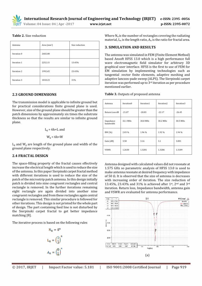
Antenna designed with calculated values did not resonate at 1.575 GHz so parametric analysis of HFSS 13.0 is used to make antenna resonate at desired frequency with impedance of 50 Ω. It is observed that the size of antenna is decreases with increasing order of iteration. The size reduction of 13.45%, 23.43% and 31% is achieved after 1st, 2nd and 3rd iteration. Return loss, Impedance bandwidth, antenna gain and VSWR are evaluated for antenna performance.
(a)
International Research Journal of Engineering and Technology (IRJET) e-ISSN: 2395 -0056
Volume: 04 Issue: 04 | Apr -2017 www.irjet.net p-ISSN: 2395-0072
© 2017, IRJET | Impact Factor value: 5.181 | ISO 9001:2008 Certified Journal | Page 920
(b)
(c)
(d)
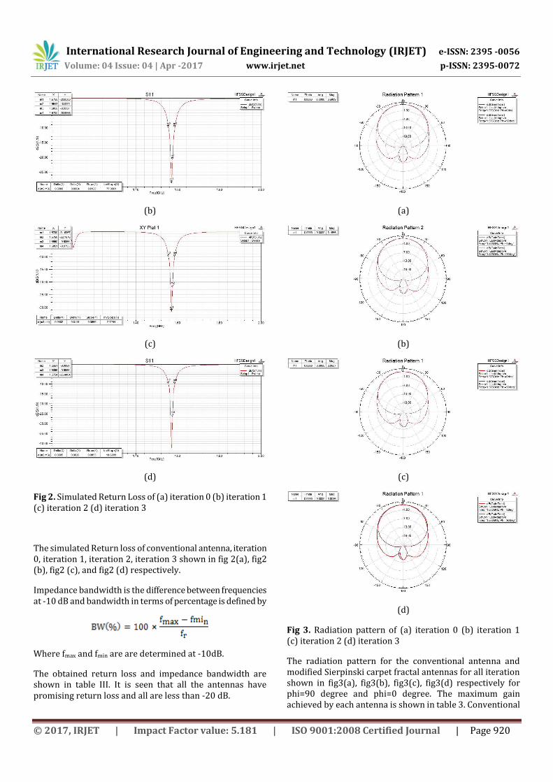
Fig 2. Simulated Return Loss of (a) iteration 0 (b) iteration 1 (c) iteration 2 (d) iteration 3
The simulated Return loss of conventional antenna, iteration 0, iteration 1, iteration 2, iteration 3 shown in fig 2(a), fig2 (b), fig2 (c), and fig2 (d) respectively.
Impedance bandwidth is the difference between frequencies at -10 dB and bandwidth in terms of percentage is defined by
Where fmax and fmin are are determined at -10dB.
The obtained return loss and impedance bandwidth are shown in table III. It is seen that all the antennas have promising return loss and all are less than -20 dB.
(a)
(b)
(c)
(d)
Fig 3. Radiation pattern of (a) iteration 0 (b) iteration 1 (c) iteration 2 (d) iteration 3
The radiation pattern for the conventional antenna and modified Sierpinski carpet fractal antennas for all iteration shown in fig3(a), fig3(b), fig3(c), fig3(d) respectively for phi=90 degree and phi=0 degree. The maximum gain achieved by each antenna is shown in table 3. Conventional

International Research Journal of Engineering and Technology (IRJET) e-ISSN: 2395 -0056
Volume: 04 Issue: 04 | Apr -2017 www.irjet.net p-ISSN: 2395-0072
© 2017, IRJET | Impact Factor value: 5.181 | ISO 9001:2008 Certified Journal | Page 921
antenna have highest gain of 3.58 dB and its iterations have slightly reduced gain.
(a)
(b)
(c)
(d)
Fig 4. VSWR of (a) iteration 0 (b) iteration 1 (c) iteration 2 (d) iteration 3
4. CONCLUSION
In this paper, Sierpinski carpet fractal patch antenna operating at a single L1 band frequency (1.575 GHz) having very significant size reduction is presented. The proposed design uses 50 Ω transmission feeding line for the impedance matching with the antenna. The size reduction is achieved through the fractal iterations up to 3rd order without affecting antenna performance such as return loss, impedance bandwidth, antenna gain and VSWR.
REFERENCES [1]T. K. Lo and Y. Hwang,” Microstrip Antennas of Very High Permittivity for Personal Communications,” 1997 Asia Pacific Microwave Conference, pp. 253–256 [2] H. Mosallaei and K. Sarabandi,” Design and Modelling of Patch antenna Printed on Magneto-Dielectric Embedded-Circuit Meta-substrate,” IEEE Transactions on Antennas and Propagation, Vol. 55, No. 1, January 2007.
[3] J. Anguera, C. Puente, C. Borja, R. Montero, and J. Soler,” Small And High-Directivity Bow-Tie Patch Antenna Based On The Sierpinski Fractal,” Microwave And Optical Technology Letters ,Vol. 31, No. 3, November 5 2001. [4] J. P. Gianvittorio and Y. Rahmat-Samii, “Fractal Antennas: A Novel Antenna Miniaturization Technique, and Applications,” IEEE Antenna’s and Propagation Magazine, Vol. 44, No. 1, February 2002. [5] J. Anguera, E. Martínez, C. Puente, C. Borja, and J. Soler, “Broad-Band Dual-Frequency Microstrip Patch Antenna With Modified Sierpinski Fractal Geometry,” IEEE Transactions On Antennas And Propagation, Vol. 52, No. 1, January 2004. [6] S. Sheik Mohammed, K. Ramasamy, and T. Shanmuganantham, “A Sierpinski Fractal Based Microstrip Patch Antenna for Wireless Power Transmission System,” ©2010 International Journal Of Computer Applications (0975 – 8887), Volume 1 – No. 13. [7] C. Borja and J. Romeu,”On the Behavior of Koch Island Fractal Boundary Microstrip Patch Antenna,” IEEE Transactions on Antennas and Propagation, Vol. 51, No. 6, June 2003.
[8] I. Surjati, Y. KN, and A. Astasari,”Microstrip patch antenna fed by inset microstrip line for Radio Frequency Identification (RFID)," Asia- Pacific International Symposium on Electromagnetic Compatibility, Beijing, China, April 12 - 16, 2010. [9] Constantine A. Balanis, Antenna theory analysis and design, Third edition, A JOHN WILEY & SONS, INC. PUBLICATION.
[10] M. Ramesh and YIP KB,” Design Formula for Inset Fed Microstrip Patch Antenna,” Journal of Microwaves and Optoelectronics, Vol. 3, No 3, December 2003.