
Gain Enhancement of Pyramidal Horn Antenna using EBG...
5
International Journal of Current Engineering and Technology E-ISSN 2277 – 4106, P-ISSN 2347 – 5161 ©2015INPRESSCO ® , All Rights Reserved Available at http://inpressco.com/category/ijcet Research Article 3290| International Journal of Current Engineering and Technology, Vol.5, No.5 (Oct 2015) Gain Enhancement of Pyramidal Horn Antenna using EBG Technique Sheelu Cyriac †* , Aparna Sankarasubramaniam ‡ and Tomson Devis † † Department of Electronics & Communication, St. Joseph’s College of Engineering and Technology, Palai, India ‡ Verdant Telemetry and Antenna Systems, Cochin, India Accepted 30 Sept 2015, Available online 02 Oct 2015, Vol.5, No.5 (Oct 2015) Abstract The conventional pyramidal horn antenna has been used for microwave applications for a very long time. Its gain can be increased by enlarging the construction of the horn to flare exponentially. This work intends to present a method for gain enhancement of conventional pyramidal horn antenna in the frequency range 2.2 GHz to 8 GHz using Electromagnetic Band Gap(EBG) without construction enlargement. It has been proved that proper utilizations of EBG structures can enhance the performance of low profile antennas. So here a new EBG technique, which is the modified version of mushroom-like EBG structure, is employed in the pyramidal horn antenna. This method improves the antenna performance such as increasing the antenna gain and reducing back radiation. The simulation was done in Ansoft HFSS 13.0. Keywords: Pyramidal horn antenna, Electromagnetic Band Gap(EBG), Mushroom-like EBG. 1. Introduction 1 A horn antenna is widely used as antenna at Ultra-High Frequency (UHF) and microwave frequency, above 300 MHz and it provides high gain as compared to the other antennas. Thus the horn antenna is widely applied for various purposes. It has been used in many applications, such as satellite communications, radio astronomy, remote sensing etc. They are used in larger antenna structures as feeders, to measure the gain of other antennas as standard calibration antennas, and as directive antennas. Advantages of horn antenna over other types of antennas are: (a) In order to achieve higher bandwidth, high data rate systems needs to be operated at a higher frequency range. This can be easily attained using a horn antenna (b) Design of a horn antenna is less complex as compared to phased array and corrugated antennas. (c) Feeding a horn antenna is not a difficult as compared to other antennas which require complex feeding techniques (d) If horn antenna is properly designed and optimized, then side lobes can be reduced to very low levels. (e) Power handling capability of a horn antenna is more advanced than other antennas as it is waveguide fed antenna, which is found useful in satellites, radars and many other applications making it an ideal choice for space applications. *Corresponding author: Sheelu Cyriac; Tomson Devis is working as Senior Engineer In the early days, horns were used widely in terrestrial microwave communications. Horn antennas are used in communication satellites, remote sensing satellites, weather and geographic information satellites. They are also used for various space programs of ESA and NASA (M.Ameena banu et al, 2013). Of the different types of horn antennas, pyramidal horn is the best horn as it has identical radiation patterns in both E-plane and H-plane along with its high gain and directivity. So, there is a need to develop a wideband horn antenna for communication and calibration needs. With the development of measurement, communication system, radar applications and electromagnetic, the pyramidal horn antenna has been widely used which made it one of the most used antennas. So this horn antenna can productively extend the working bandwidth of the antenna and enhance the impedance matching levels between waveguide and free space (M.Ameena banu et al, 2013). 2. Design of simple pyramidal horn antenna The pyramidal horn antenna has mainly two parts: a rectangular waveguide and the flared part of the horn. Among waveguide types rectangular waveguides are used to transfer large amounts of microwave power at frequencies greater than 3 GHz. In order to design a pyramidal horn antenna in the frequency range 2.2
Transcript of Gain Enhancement of Pyramidal Horn Antenna using EBG...

International Journal of Current Engineering and Technology E-ISSN 2277 – 4106, P-ISSN 2347 – 5161 ©2015INPRESSCO®, All Rights Reserved Available at http://inpressco.com/category/ijcet
Research Article
3290| International Journal of Current Engineering and Technology, Vol.5, No.5 (Oct 2015)
Gain Enhancement of Pyramidal Horn Antenna using EBG Technique
Sheelu Cyriac†*, Aparna Sankarasubramaniam‡ and Tomson Devis†
†Department of Electronics & Communication, St. Joseph’s College of Engineering and Technology, Palai, India
‡Verdant Telemetry and Antenna Systems, Cochin, India Accepted 30 Sept 2015, Available online 02 Oct 2015, Vol.5, No.5 (Oct 2015)
Abstract The conventional pyramidal horn antenna has been used for microwave applications for a very long time. Its gain can be increased by enlarging the construction of the horn to flare exponentially. This work intends to present a method for gain enhancement of conventional pyramidal horn antenna in the frequency range 2.2 GHz to 8 GHz using Electromagnetic Band Gap(EBG) without construction enlargement. It has been proved that proper utilizations of EBG structures can enhance the performance of low profile antennas. So here a new EBG technique, which is the modified version of mushroom-like EBG structure, is employed in the pyramidal horn antenna. This method improves the antenna performance such as increasing the antenna gain and reducing back radiation. The simulation was done in Ansoft HFSS 13.0. Keywords: Pyramidal horn antenna, Electromagnetic Band Gap(EBG), Mushroom-like EBG.
1. Introduction
1 A horn antenna is widely used as antenna at Ultra-High
Frequency (UHF) and microwave frequency, above 300
MHz and it provides high gain as compared to the other
antennas. Thus the horn antenna is widely applied for
various purposes. It has been used in many
applications, such as satellite communications, radio
astronomy, remote sensing etc. They are used in larger
antenna structures as feeders, to measure the gain of
other antennas as standard calibration antennas, and
as directive antennas. Advantages of horn antenna over
other types of antennas are: (a) In order to achieve
higher bandwidth, high data rate systems needs to be
operated at a higher frequency range. This can be
easily attained using a horn antenna (b) Design of a
horn antenna is less complex as compared to phased
array and corrugated antennas. (c) Feeding a horn
antenna is not a difficult as compared to other
antennas which require complex feeding techniques
(d) If horn antenna is properly designed and
optimized, then side lobes can be reduced to very low
levels. (e) Power handling capability of a horn antenna
is more advanced than other antennas as it is
waveguide fed antenna, which is found useful in
satellites, radars and many other applications making
it an ideal choice for space applications.
*Corresponding author: Sheelu Cyriac; Tomson Devis is working as Senior Engineer
In the early days, horns were used widely in terrestrial microwave communications. Horn antennas are used in communication satellites, remote sensing satellites, weather and geographic information satellites. They are also used for various space programs of ESA and NASA (M.Ameena banu et al, 2013).
Of the different types of horn antennas, pyramidal
horn is the best horn as it has identical radiation
patterns in both E-plane and H-plane along with its
high gain and directivity. So, there is a need to develop
a wideband horn antenna for communication and
calibration needs. With the development of
measurement, communication system, radar
applications and electromagnetic, the pyramidal horn
antenna has been widely used which made it one of the
most used antennas. So this horn antenna can
productively extend the working bandwidth of the
antenna and enhance the impedance matching levels
between waveguide and free space (M.Ameena banu et
al, 2013).
2. Design of simple pyramidal horn antenna
The pyramidal horn antenna has mainly two parts: a
rectangular waveguide and the flared part of the horn.
Among waveguide types rectangular waveguides are
used to transfer large amounts of microwave power at
frequencies greater than 3 GHz. In order to design a
pyramidal horn antenna in the frequency range 2.2

Sheelu Cyriac et al Gain Enhancement of Pyramidal Horn Antenna using EBG Technique
3291| International Journal of Current Engineering and Technology, Vol.5, No.5 (Oct 2015)
GHz to 8 GHz, first a rectangular waveguide has to be
designed. The standard dimensions of the rectangular
waveguide selected for the current design are:
a = 72.136 mm
b = 34.036 mm, where a and b are the width and height of the rectangular waveguide. Now in order to calculate the length of the waveguide, we use the equation,
gL 75.0 (1)
where λg is the wavelength corresponding to the center frequency of the waveguide. Therefore, here length of the waveguide, L = 81.67 mm.
The dimensions of horn antenna to be used for the selected waveguide are: A = 153.4 mm; B = 120.53 mm; C = 254 mm
Fig.1 Geometry of the proposed antenna
Fig.2 Simulated pyramidal horn antenna
The gain-frequency plot, radiation pattern, plot of S11
and VSWR of the simulated pyramidal horn antenna are shown below.
Fig.3 Gain-Frequency plot of the pyramidal horn antenna
Fig.4 Radiation pattern of the pyramidal horn antenna
Fig.5 S11 plot of the pyramidal horn antenna
Fig.6 VSWR plot of the pyramidal horn antenna The designed pyramidal horn antenna has a gain of 13.3 dB at 3 GHz. The antenna also has a decent reflection coefficient plot from 2.2 GHz to 8 GHz as shown in the figure below. Also the VSWR values of the antenna ensures that it works well in the desired band.
3. The EBG structure
The Electromagnetic-Band Gap (EBG) structures are artificially made periodical cells composed of metallic or dielectric cells. The major characteristic of EBG
Sheelu Cyriac et al Gain Enhancement of Pyramidal Horn Antenna using EBG Technique
3292| International Journal of Current Engineering and Technology, Vol.5, No.5 (Oct 2015)
structures is to exhibit band gap feature in the suppression of surface-wave propagation. This feature helps to enhance antenna's performance such as increasing the antenna gain and reducing back radiation. EBG structures are always used in microwave devices in order to improve the performance of the devices especially to improve the radiation and to decrease the noise or losses in transmissions. EBG structures are classified into three depending upon their geometry: a) one dimensional (1-D), b) two dimensional (2-D) and c) three dimensional (3-D) periodic structures. The 2-D EBG structures have substantial advantages in terms of compactness, stability, and fabrication, which make them more attractive for microwave devices. 3.1 The mushroom-like EBG structure The mushroom-like EBG structure is a kind of 2D EBG structure, which is widely used in antennas. This particular structure was chosen because it is used widely for gain enhancement and is easy to fabricate. The mushroom-like EBG structure consists of rectangular patches that are arranged periodically in arrays, a substrate and the ground plane. Each rectangular cell is connected to the ground plane using a vias in the form of a cylindrical structure.
Fig.7 Mushroom-like EBG structure
Considering the design of the mushroom-like EBG structure, the various parameters involved are: W = 0.12λ, where W is the width of the patch and λ is the wavelength corresponding to the operating frequency. g = 0.02λ, where g is the gap between EBG cells. h = 0.04λ , where h is the height of the substrate. εr = 2.2, is the dielectric constant. r = 0.005λ, where r is the radius of the vias. Thus the EBG structure can be designed and the material used for substrate is Rogers RT/duroid.
The thickness of the substrate available is 1.6 mm. Therefore we design the parameters of the mushroom-
like EBG structure accordingly. The dimensions of the mushroom-like EBG structure used in this design are:
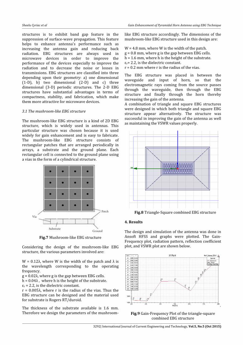
W = 4.8 mm, where W is the width of the patch. g = 0.8 mm, where g is the gap between EBG cells. h = 1.6 mm, where h is the height of the substrate. εr= 2.2, is the dielectric constant. r = 0.2 mm where r is the radius of the vias.
The EBG structure was placed in between the waveguide and input of horn, so that the electromagnetic rays coming from the source passes through the waveguide, then through the EBG structure and finally through the horn thereby increasing the gain of the antenna. A combination of triangle and square EBG structures were designed in which both triangle and square EBG structure appear alternatively. The structure was successful in improving the gain of the antenna as well as maintaining the VSWR values properly.
Fig.8 Triangle-Square combined EBG structure 4. Results
The design and simulation of the antenna was done in Ansoft HFSS and graphs were plotted. The Gain-Frequency plot, radiation pattern, reflection coefficient plot, and VSWR plot are shown below.
.
Fig.9 Gain-Frequency Plot of the triangle-square combined EBG structure
Sheelu Cyriac et al Gain Enhancement of Pyramidal Horn Antenna using EBG Technique
3293| International Journal of Current Engineering and Technology, Vol.5, No.5 (Oct 2015)
Fig.10 Radiation pattern of the triangle-square combined EBG structure
Fig.11 VSWR Plot of the triangle-square combined EBG structure
Fig.12 Reflection coefficient of the triangle-square combined EBG structure
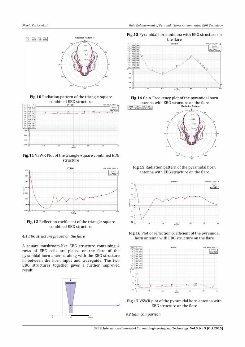
4.1 EBG structure placed on the flare A square mushroom-like EBG structure containing 4 rows of EBG cells are placed on the flare of the pyramidal horn antenna along with the EBG structure in between the horn input and waveguide. The two EBG structures together gives a further improved result.
Fig.13 Pyramidal horn antenna with EBG structure on the flare
Fig.14 Gain-Frequency plot of the pyramidal horn antenna with EBG structure on the flare
Fig.15 Radiation pattern of the pyramidal horn antenna with EBG structure on the flare
Fig.16 Plot of reflection coefficient of the pyramidal horn antenna with EBG structure on the flare
Fig.17 VSWR plot of the pyramidal horn antenna with EBG structure on the flare
4.2 Gain comparison

Sheelu Cyriac et al Gain Enhancement of Pyramidal Horn Antenna using EBG Technique
3294| International Journal of Current Engineering and Technology, Vol.5, No.5 (Oct 2015)
Now a comparison of the original simple pyramidal horn antenna without EBG structure, the horn antenna with EBG structure in between the waveguide and horn input and the antenna with EBG structure in the flare, in addition to the structure in between horn input and waveguide is done.
Table 1 Gain comparison
Fre
qu
ency
(GH
z)
Gai
n w
ith
ou
t E
BG
(dB
)
Gai
n w
hen
EB
G
is
pla
ced
in
bet
wee
n
wav
egu
ide
& h
orn
in
pu
t(d
B)
Gai
n w
hen
EB
G
stru
ctu
re is
pla
ced
at
two
loca
tio
ns(
dB
) 2.2 12.8 14.35 22
3 7 14.2 16.2
4 12.5 17.3 15.8
5 17.9 17.3 17.3
6 16.2 15.9 19.3
7 11.3 19.7 16.54
8 9.9 20.7 13.27
Conclusions The newly designed structure ensures an improved gain from 2.2 GHz to 8 GHz compared to the antenna without EBG structure. Since the mushroom-like EBG structure is a 2D structure it does not make the antenna bulky. This gain enhancement method using the new triangle-square EBG structure is unique and has not been used anywhere till date. The antenna can be used for different applications such as wireless communication, laboratory purposes, radar applications and satellite communications. From Table 1, it can be concluded that the gain of a pyramidal horn antenna has improved maximum up to 9.8 dB with a decent VSWR. Depending upon the need either a single EBG structure or both together can be used. So this provides a very effective way to improve gain of a pyramidal horn antenna.
References Kampeephat, P. Krachodnok, R. Wongsan, (2014)
Efficiency Improvement for Conventional Rectangular
Horn Antenna by Using EBG Technique, World Academy
of Science, Engineering and Technology International
Journal of Electrical, Computer, Electronics and
Communication Engineering, Vol:8, No:7.
M. Ameena banu, N.R.Indira, M .Pandimadevi, (2013)
Design of Pyramidal Horn Antenna for UWB
Applications, International Journal of Advanced Research
in Computer and Communication Engineering, Vol. 2,
Issue 7.
Matthew A. Koerner, (2000) Gain Enhancement of a
Pyramidal Horn Using E- and H-Plane Metal Baffles,
IEEE Transactions On Antennas And Propagation,
Volume 48, No.4.
Fan Yang, Yahya Rahmat-Samii, (2009) Electromagnetic
Band Gap Structures in Antenna Engineering, Cambridge
University Press.
Constantine A. Balanis, (1997) Antenna Theory Analysis
and Design, John Wiley & sons Inc., Newyork.


![PERFORMANCE COMPARISON OF PYRAMIDAL HORNS LOADED … · 2018-01-14 · exhibits monotonically increasing gain behavior, a salient feature of the horn antenna [2,17,18], a return loss](https://static.fdocuments.us/doc/165x107/5e96032ae78896401776064e/performance-comparison-of-pyramidal-horns-loaded-2018-01-14-exhibits-monotonically.jpg)


