MINE MACHINERY-II ( THEORY 2 ) 1.0 Underground …mineportal.in/assets/study_material/MINING...
32
1 MINE MACHINERY-II ( THEORY 2 ) 1.0 Underground face machineries. 1.1 Electric coal drill. This drill used for drilling holes in coal and similar soft rock is electrically operated and is of rotary type. Such drills are manufactured by a few companies like MAMC, Voltas, Chanda & co and others. Coal drills manufactured are of 2 types. 1. Type CD-1 (with steel body) 2. Type CD-2 (with aluminum body) The steel body drill (type CD-1) weight 21.5 kgf and the aluminum body drill weight 17.5 kgf. The coal drill is used not only for coal but other rocks in coal mines expect very hard grade of stone. 1.1.1 Describe constructional features, operation, principle & use of electric coal drill. 1. The drill essentially contains a squirrel cage induction motor is a flame proof with two hand grips symmetrically placed on two sides of the machine. 2. The switching device is placed under the right hand grip of the motor casing while the cable entry is but the left handgrip through the plug & socket arrangement. 3. The output power of the motor which has two poles is FKW half hourly rotated & is wound for 125 volts, 3 phage, 50 cycles AC supply. 4. The powers supplied through the 6.5mm 2 . 5 core trailing cable of 100 m long from a drill panel which receives power at 550 volt by armoured cable & steps it down to 770 volt. 5. The drill machine comprises of (i) Drill machine. (ii) Drill rod. (iii) Drill bit. 1.1.2 State types of drill rods & drill bits used in electric coal drill. Drill rod : 1. The drill rod is of diamond section for drilling in coal and it fits in the drill chuck by a beyond joint but the bit is attached to the rod by a wire nail. 2. Tungsten carbide typed drill bits are used and of these the eccentric type bit in employed in coal. 3. The rate of penetration of bit in coal is generally 1.5mt / min. 4. The drill is capable of drilling holes each 1.5mt deep in a shaft of 8 hours. Drill bit : The different types of drill bits used in the element coal drill are, (i) Eccentric type. (ii) Concentric type. (iii) VEE type. In coal mine of western coal fields Ltd. the drill was used in galleries 4.5m in wide 42.6m high the coal yield per blasting was nearly 25te. 1.2 Describe basic construction features of gathering arm loader, scraper loader, side discharge loader & load & haul loader. Gathering Arm Loader : It consists of 3 principle units. (i). A gathering head. (ii) A central crawler mounted chassis. (iii) A rear boom or jib.
-
Upload
nguyentuyen -
Category
Documents
-
view
216 -
download
1
Transcript of MINE MACHINERY-II ( THEORY 2 ) 1.0 Underground …mineportal.in/assets/study_material/MINING...
1
MINE MACHINERY-II ( THEORY 2 ) 1.0 Underground face machineries.
1.1 Electric coal drill. This drill used for drilling holes in coal and similar soft rock is electrically operated and is of rotary type. Such drills are manufactured by a few companies like MAMC, Voltas, Chanda & co and others. Coal drills manufactured are of 2 types.
1. Type CD-1 (with steel body) 2. Type CD-2 (with aluminum body)
The steel body drill (type CD-1) weight 21.5 kgf and the aluminum body drill weight 17.5 kgf. The coal drill is used not only for coal but other rocks in coal mines expect very hard grade of stone.
1.1.1 Describe constructional features, operation, principle & use of electric coal drill.
1. The drill essentially contains a squirrel cage induction motor is a flame proof with two hand grips symmetrically placed on two sides of the machine.
2. The switching device is placed under the right hand grip of the motor casing while the cable entry is but the left handgrip through the plug & socket arrangement.
3. The output power of the motor which has two poles is FKW half hourly rotated & is wound for 125 volts, 3 phage, 50 cycles AC supply.
4. The powers supplied through the 6.5mm2. 5 core trailing cable of 100 m long from a drill panel which receives power at 550 volt by armoured cable & steps it down to 770 volt.
5. The drill machine comprises of (i) Drill machine. (ii) Drill rod. (iii) Drill bit.
1.1.2 State types of drill rods & drill bits used in electric coal drill. Drill rod :
1. The drill rod is of diamond section for drilling in coal and it fits in the drill chuck by a beyond joint but the bit is attached to the rod by a wire nail.
2. Tungsten carbide typed drill bits are used and of these the eccentric type bit in employed in coal.
3. The rate of penetration of bit in coal is generally 1.5mt / min. 4. The drill is capable of drilling holes each 1.5mt deep in a shaft of 8 hours.
Drill bit : The different types of drill bits used in the element coal drill are, (i) Eccentric type. (ii) Concentric type. (iii) VEE type. In coal mine of western coal fields Ltd. the drill was used in galleries 4.5m in wide 42.6m high the coal yield per blasting was nearly 25te.
1.2 Describe basic construction features of gathering arm loader, scraper loader, side discharge loader & load & haul loader.
Gathering Arm Loader : It consists of 3 principle units. (i). A gathering head. (ii) A central crawler mounted chassis. (iii) A rear boom or jib.
2
1. A chain conveyor extending from the gathering head up to the boom end is transporting medium, conveying coal gathered from the face to the receiving mine car, tub, conveyor or shuttle car.
2. The gathering arms are operated by twin crank discs. This discs are, flush with the working surface of the head.
3. There is a separate driving motor for each of the arm. 4. The rate of loading depends upon the no of the strokes/men and the conveyor speed is
also related to the rate of loading of the gathering arms. 5. There variable speeds are available on the loader for gathering speed of the arms. 6. The ramp of gathering head can be raised or lowered usually through 0.5m. 7. Hydraulic jacks are used for elevation of the gathering head and they are controlled by
the operator form this position at the controls. 8. At the face as the loader loads cowl it has to move forward to be close to coal heap and
in a gallery width of 4 to 4.8 m to and for movement of the machine are frequent for cleaning up the gallery.
Scraper Loader :
1. The machine is diesel operated with pneumatic tyrest wheel & has at the centre a bowl fitted with a cutting blade at bottom.
2. As a scraper is pushed forward by a dozer its blade cuts a thin slice of earth usually between 75mm & 225mm thick over a distance of nearly 30m.
3. The earth is automatically collected in a central bowl whose capacity ranges from 3m3 to 22m3 and it takes nearly one minute for loading.
4. When the scraper is fully loaded its bottom opening closed by the operator through manipulation of a cable & the loaded scraper with the bowl ligted travel the dumping yards on its power.
5. At the dumping yard as the scraper moves the bottom opening of the bowl is opened & the contents are unloaded is a layer 150mm to 250mm thick over a distance of 30 to 70 m. the bowl is always bottom discharging.
6. Scrapers are used in coal mines for cutting and transport weather sand stone as well as coal.
7. The coal excavated by it is however smaller size 4 scraper may take 5 to 6 minute for a complete cycle of loading & unloading, if the total up & down distance of a trip in nearly 300m.
3
Side Discharge Loader : 1. SDL are crawler mounted machine which have been designed for loading broken coal or
ore in to a conveyor or directly in to mine tubs. 2. They are capable of turning in its own length but not designed for continuous travel. 3. SDL is not considered as a transport system as it travels with materials for a short
distance. 4. The crawler mounted machine can operate on steep gradient up to 7m to 14m in favour
of or against the load and cross gradient up to 1 in 8. 5. It can operate on much safer floor than rubber tyred machine. 6. SDL are made with flameproof motors are for use in underground coal mines. It operates
with 40HP motor on either 550 or 1100 volts & accommodate 45m of type 11 cable or 30m of type 7 cable.
7. The speed of machine is 3.86km/hr for special application they are fitted with remote control arrangements.
Applicability :
Gradient 1 in 4.
Floor condition: it can be used on bad floor, soft floor, also in wet or muddy floor.
Roof condition: It prefers good roof. Advantages :
High output.
Less operating cost.
Low maintenance required. Disadvantages :
Additional ventilation required due to heat.
Initial investment is high.
Trailing cable create problem. Load & Haul Loader :
1. As the name implies it is a mining equipment that performs loading, hauling & discharging of bulk materials.
2. LHD are typically track less & the term is usually restricted to vehicle used underground. 3. Since LHD are convinced for underground mining they are compact & laws profile. 4. For surface operation it is usually preferred to use separate machines for loading &
hauling as well as dumping. 5. The LHD are rubber tyred mounted machine driven by flame proof electric motor or by a
flame proof diesel engine. 6. LHD are normally used on gradient up to 1 in 6. 7. The maximum speed is 8-10km/hr when empty & 3-5 km/hr when loaded. Applicability :
Gradient 1 in 6.
Floor condition: required strong & good floor.
4
Roof condition: required good roof.
Maximum speed for empty 8-10km/hr.
Maximum speed for loaded 3-5km/hr.
1.3 Describe basic constructional features & operation principle of jack hammer drill & air leg drill.
Jack Hammer Drill : 1. It is a compressed air operated drill to which air is supplied from external compressors
through hose pipes at a pressure of about 6kgf/cm2. 2. It is a hard held drill used for vertically downward drilling. 3. The drill weight 15 to 25kgf and drill holes of dia 30mm to 38mm up to 3m depth. 4. The drill rod is hexagonal in cross section. Suitability shaped it one end of the to form the
shank & the other choice so shaped as to form a non-detachable single chisel bit with a tungsten carbide insert.
5. Drill rod may also be equipped with detachable x-type tungston carbide drill bit. 6. When handheld the machine drills vertically download holes only but it mounted on air
legs, it may be used for drilling inclined holes. 7. An oil bottle (lubricant) placed between the drill and the air receiver & connected by hose
pipes to both, provides lubrication to the drill when working. 8. For dust suppression a jackhammer can be adopted to wet drilling by some
modifications, so that the drill cuttings mixed with water come out of the hole in the form of sludge.
9. The air consumption is generally 2-2.5m3 of free air/min. Air Leg Drill :
1. Where compressed air is the motive powerful drills, air legs may be advantageously used to mount the compressed air drills.
2. An air leg is essentially a long cylinder in which a piston is actuated by compressed air controlled valve which is also used to release the air pressure to lower the piston.
3. An air leg relievers the operator of the fatigue involved in holding the drill & keeping it pressed forward as the leg exerts on upward lifts a forward feeding pressure on the drill.
4. The air leg does not increases the rate of penetration on fund & it is used for drills upto 2m in height.
5
1.4 Describe basic constructional features & operation principle of road header & Shearer loader.
Road header : 1. The modern method at 1st drivages of tunnel road in coal as well as soft rock like sand
stone. 2. Among the machine marked by posco ENGG company are the light duty medium duty
and heavy duty machine. 3. The road header mk-2A manufactured by posco its weight only 23 tonne. 4. The boom has axially for road heating manufacture by posco is k/a drift header. 5. It has a cutting of 1.72 m wides. 6. It weight only 16 tonne and exert a ground pressure 924 N/m2. 7. The trucks are hydraulically operated even a working speed of 0.03 m/sec. 8. The willing cycle started by sampling at the floor level and than raising to take out.
Shearer loader : It is popularly called shear is short is basically a normal coal cutter with the chain & jib replaced by a horizontal drum lifted with picks. It is mounted on a skid plate provided with bearing pegs which rest on a A.I.C. The machine consists of 3 units.
1. Cutting units : It consists of a special gear box which drives a horizontal at shaft towards the face. Shearing drums are shearing disc lifted intension of the shaft. The shearing drum can be raised/lowered in a vertical plane with the half of ranging for cutting at various heights.
2. Haulage unit : The travel of shearer loader is effected with the shaft of a chain haulage mechanical controls with hydraulic system. In the haulage system which is mechanically controlled only multifixed haulage speed are possible. In the hydraulic system operation by hydraulic controls provides indefinitely variable speed a travel which various from 0-0.12m/sec.
3. Motor unit : It provides power from 225kw with the half of a single electric motor/two motors at a maximum voltage of 4.2kw of 50 cycle, 3(phase), A.C supply.
2.0 Opencast machineries: 2.1 Describe basic constructional features of surface miner, dragline, shovel & backhoe, bucket wheel excavator. Surface miner :
1. It is circular mounted machine. 2. The cutting drum has helix vanes over which tungsten carbide tipped cutting bits are
mounted. 3. A shield coal is fitted behind the drum. 4. Due to the rotation of the cutting drum the material is cut, crushed between the helix and
coal. 5. The material is passed through on intake channel in the shield (coal) into the loading
conveyor behind it. 6. The height of the discharge conveyor is also adjustable. 7. The cutting drum is operated by pole charging squirrel cage induction motor. 8. It can be raised up lower down and fitted in the traverse education by the hydraulic
range. 9. The machine runs of 3 (300m) 0.04 (3800cm) crawler units. 10. The cutting drums of 3000/3800 width. Application : 1. Mining of this seam deposited. 4. Remove the partings. 2. Creating channel. 5. road construction & maintenance. 3. Digging exploratory trenches.
6
Advantages of Surface miner : 1. It eliminates drilling and blasting. 2. It is very good to environmental condition. 3. Primary crushing of material is not needed. 4. Installation cost is very low. 5. Manpower requirement is low. 6. It has first training speed. Disadvantages of Surface miner : 1. It does not give actual size of the metal.
Dragline :
1. A dragline is an excavator which has a boom (length varies from 9 to 9.6m approx) one end of which us attached with the revolving unit of the machine & the hanging end is the entire cycle carries a large sheave for the cable attached with the bucket.
2. It is made of lattice construction by the structural steel which is lowered down or raised up by the cable of boom hoist.
3. For dragging the bucket towards machine one end of a dragline cable is attached with the bucket & the other end is connected to the drag hoist via fairlead which is at the foot of the boom.
4. The bucket is fitted up by dragging or pulling the bucket against the then it is hoisted up by the hoist cable.
5. Finally it dumps the material direct by over the spoil dumper over the trucks or railway wagons.
6. Generally the draglines are used for direct handling & re-handling of overburden material during over casting since it is the cheapest means of overburden removal.
7. It is used only soft & unconsolidated materials, blasted rock or mineral coal top soil, re-handling of ore or coal stock pole etc.
8. Since the dragline booms are longer in length it can dig well below & above the shovel where it stand & has higher flexibility in operating condition compare to a shovel.
System of working : 1. The dragline may be either crawler mounted, wagon mounted, track mounted or walking
type. 2. The bottom can move both vertically (from horizontal) 25° to 60° & horizontally 0° to 108°
with the help of swing mechanism to perform the job. 3. Rear end of the box shaped bucket whose one end is open is attached by means of two
hoist chains are fitted with a dumps sheave. 4. A dragline is operated by diesel engine or a motor which is external source through a
trailing cable. 5. The drag chains are attached is the front side of the bucket at one end while the other
end is connected with a drag yoke. The drag chains are connected to the drag cable by dragline socket.
6. Bucket weight, design and balance together with the angularity if the drag cable (angle around 10° to 18°) Forces etc are the main parameters of penetration of the bucket in to the material being excavated by a dragline.
7. The material of the heavy bucket lip & teeth are made of manganese steel. 8. Swinging, hoisting & acceleration after digging require maximum power demand. 9. Leveling & grading with the help of dozer is very essential. 10. Efficiency of a dragline is reduced * machine abuse is increased when it digs materials
from the working faces above its level. 11. For OB removal a dragline is more mobile & versatile machine compare to a shovel
although its loading efficiency is less. 12. In case of softer deeper OB is wet & geologically disturbed pit a dragline can work more
efficiency compared to a shovel. It can also efficiency be used for receiving mineral from placer deposit.
7
Loading Capacity : A dragline is capable of dealing with the following quantities of rock/earth (solid) in a year. 12 to 14 hour work per day. Bucket Size Million m3
4.5 to 7.5m3 (6 to 10 cycle)----------------- 0.25 to 0.75 11.5 to 15m3 (15 to 20 cycle)-------------- 1.5 to 1.7 25 to 30m3 (30 to 40 cycle)----------------- 3 to 4.5
Applicability Condition : It is suitable for digging alluvium, sandy soil, unconsolidated rocks or blasted coals. It is generally used for handling softer material so the ground must be soft or medium hard ground. Advantages of Dragline :
1. In the soft mineral deposit the dragline can operate efficiently companied to the shovel. 2. In the presence of hopper- reload or dragline can material into railway wagon belt
conveyor & other transport facility. 3. Superior is wet pts. 4. Its maintenance cost is cheap. 5. It has more flexibility in operation.
Disadvantage of Dragline : 1. It is used for softer rock formation. 2. It has lesser spotting ability. 3. It has lesser output than the powered shovel. 4. Production cost is more as compared to the powered shovel.
Shovel :
1. A shovel is a equipment which excavates the rock or ore by digging from its operating base to upwards and dump it either on a dumper or railway wagon or over the spoil dump.
2. It is a highly productive machine & capable to handle all types of ores rocks, ranging from line to very hard blocky dumps has lower operating cost, higher production & productivity etc.
3. it requires less man power to operate less wire rope coal & less surface preparation. 4. It can also load in various mining conditions has longer life higher ability by & can also do
production by staying in the inclined terrain. 5. Shovel can be used in strip mining method (loading, swinging, dumping of OB material
into the adjoining excavate area by over casting) in tanclem operation (where 2 or more shovels are used for re-handling of OB successively). Shovel pull back operation which is a combination of a shovel & dragline for handling OB. Digging a deeper cut loading & over casting by the shovel & pull back the spoil material by a dragline into the excavated
8
area, removal of OB in the contour mining in the hilly terrain OB removal of top soil, construction of aces roads and haul roads, opening a mine by a box cut systematic.
6. A flat on mild gradient dry competent floor is a very good operating condition for a dipper shovel (rocker shovel)
7. The design of the shovel is such that only its minimum mechanical parts like the dipper slick bucket etc play important role in digging operation.
8. The perfect motion of the deeper slick to reach & leave the face after loading facilities shorter cycle of operation. The bucket which is mounted with sharp teeth cut the ore or mineral body & breaks then with the help of pressure provided by the hoist & crowd action.
9. Efficiency of larger size shovels is much higher particularly during excavation of heavily blasted OB rock or coal.
10. During operation assistance in some time required by either a bulldozer or a front end loader to gather and muck pilling of scattered rocks or ore.
Backhoe :
1. It is also named as pull shovels drag shovel etc. 2. It dig soil, rock, or ore below the level of bench on which it stands & unload excavator
materials over a truck or railway wagon. 3. It can be displayed efficiently where the mine is very much wetted by the prolonged rain
or where seepage of water through the ground strata. 4. Generally the backhoe is very good for trenching shallow depth cutting and for basement
excavator. 5. The hoe bucket is attached to a dipper slick at its lower and facing towards the machine. 6. The middle of the deeper slick is hinged to a boom where as the top of the machine
same is attached with a rope pulley. 7. The pulley is connected by a hoist rope to a jack boom attached to the top of the main
machine body. 8. A drag rope is connected to a drag drum passing through the sheave attached to the
side of the main boom. 9. the dipper is lowered down in to position by the hoist rope, so that bucked bites in to
ground & the cutting operation in achieved by pulling the drag rope till it became as fall. 10. Afterward both the hoist drag ropes are wind up to make the bucket more closer to the
toe of the back the bucket is raised up to the dumping highly operating the hoist rope. 11. The machine is swing to unload the material over a dumper or a railway wagon or other
haulage system by paying out the drag rope, which makes the dipper hand to nearly horizontal position.
12. The bucket lifts making its face down to dump materials over the haulage limit.
9
13. The capacity of the backhoe bucket may be in the range starting form 0.38 m3 to over 18m3 & digging depth is around 4 to more than 8m & the height of discharge is more or less half the boom length.
14. As a safety measure the backhoe should be kept at a safe distance away from the crest of the bank to avoid danger arising due to caving.
15. Although it has large cycle times less efficiency in discharging material over the trucks but it can nicely be used for removing top soil & OB.
16. It is widely used for trenching & construction fields. Bucket Wheel Excavator :
1. It is suitable for long range stripping of soft OB rock at a considerable lower cost although the machine is costly having lower flexibility.
2. The machine is nicely applicable in the following conditions.
Hard & tough wall fragmented blasted rock with no or less boulders having consistency of uniform ground & bank condition.
Since it has a wide radius if excavation around 40 to 90m with high & deep cut, the width of the boom or poses more reserve & create huge amount of space for the mbile equipment. The slope of the pit is also very stable.
It can be used for selective & thick seam mining.
For easy disposal of ore or OB to the considerable distance above or below of it working level.
It is very highly efficient excavator for lignite, gift alluvium etc.
For reclamation of land. The Machine operation :
1. A bucket wheel excavator has a wheel around 2.5 to 17m dia containing 6 to 8 nos evenly spaced bucket (capacity changing from 0.04m3 to 6.3m3) around its periphery.
2. The series of buckets attached to the periphery of the wheel dig the into the mineral or softer rock mass & cut the same when the wheel rotates from bottom to top (clockwise).
3. The cut material is loading by the bucket & discharged over the belt conveyor mounted. 4. The digging depth of a big bucket wheel excavator is around 25m or below & a cutting
height of around 70m above its level & a cutting width around 100m is possible. 5. The vertical movement of the cutting boom is done by a hoist rope connected with a
structure in front of the excavator. 6. One end of the boom is attached to the swinging platform of the machine to swing the
former horizontally. 7. The cut material from the boom conveyor is discharged into a fixed conveyor & finally
the material is loaded directly either over the spoil dump or railway wagons or truck or spreader or in to the hopper of the movable belt conveyor.
10
8. Most of the bucket wheel excavators are either crawler track mounted or rail mounted. Rail mounted bucket wheel excavator are more common.
9. The rotation of the wheel is around 4 to 8 rpm cutting speed varies from 1.3 to 3.6m/sec and dig into the face around half the maximum dia of the wheel is deep digging with a digging force around 5 to 14 kgf/cm2.
10. The excavators are operated by diesel or electrically. 11. Bucket wheel excavator cuts softer mineral body or rock mass by rotating wheel, which
produces less stress & strain to the machine body. 12. Because of thin reason it also consumes less power requires less maintenance & above
all the machine requires less body weight. 13. During cutting and swinging operation the stresses & strain distributed more evenly in the
machine body & facilities lower gradual ground, hearing pressure by the crawler truck unit.
14. The rate of production by the bucket wheel excavator varies from 100 to more than 1000 m3/tonne. Machine weight varies from 35 to more than 7000 tonees & power 200kw to more than 7000 kw.
2.2 Describe basic construction features of dumper, dozer, scraper & road grader. Dumper : These are a heavy duty trucks with container body of steel open at the top for receiving material located mechanically by tractor shovel, dipper shovel, drag line etc. all dumper/tipper are provided with arrangements to life the loaded body by utilizing hydraulic pressure to force a ram out. Main units of truck/dumper are the following : The power engine : The engine at any truck system should be of high power and lower in weight. The specific power rotting to truck system varies from 6 to 8 kw/tonne of load. The engine (2 cycle or 4 cycle type) are operated mostly be diesel having super charger or turbo charger along with inter culling arrangements. The drive system : It is the system which supplies power from the engine to wheels. The system should be highly reliable longer life high steel performance and cheap. The drive system may be classified in to many categories like.
(a) Mechanical & hydro mechanical drive. (b) Hydro static drive.

11
(c) Electric drive manually operated mechanical drive contain gear (around) and coupling which are operated by air assisted clutch & gear operating system and steering mechanism.
Hydro static drive : In this system very large capacity pump is in corporate in the truck body which generate high pressure fluid (oil) & directed in the hydraulic prime mover is each of the drive wheel.
Suspension unit : To save the frame and body presently hydro pneumatic suspension system operated by nitrogen gas, compressed by oil under pressure are widely used in heavy truck for their high shock absorbing efficiency.
Hydraulic system : hoisting & lowering positional as well as operating of dumper by the hydraulic system operated by vane pump. The hydraulic ram for hoisting & lowering operation are performed by two double acting rams, the rams is connected with frame as well as with body by belt & shocked arrangement.
Body : The body of the highway truck are generally of stand are v type or modified v type made of thick high strength allow steel. The standard type body has vertically sides tippered from front rear & where has v shaped body has a consistent angle floor plate stopping towards the front from the rear end at truck having varial side. The body is also provided with reinforced lab guard at the from protection operator cabin. The body may also provided with rodier elector to clean the track fastened in between actual tyres.
Tyres : Both phayrating & size of the tyres are selected based on the amount of load gradient at the haulage heavy thrust forced on the body with the unloaded material by shovel flotation & traction requirement. Dozer : Dozer is a tractor with a pusher blades attached to the front portion. The tractor is the diesel-operated power unit equipped with either crawler chains or rubber tyred wheels for lifting. The pusher blade can be raised or lowered or tilted through small angles horizontally be rams operated pushing loose material or for digging in earth, sand and soft weathered rock. The machine is also engaged for leveling or spreading earth, for leveling of rock spoil in the dumping yard, grading and compacting temporary roads, pushing mineral into sub-ground level bunkers through grizzly, for towing dumpers, etc. it also serves the purpose of pushing boulders, pulling down trees, and is an essential equipment to push scrapers. A dozer equipped with a fork like attachment is known as ripper and operates like a plough to loosen moderately hard rock. The loosened rock may be loaded by a scraper. A dozer can dig 1.2m to 1.5m below ground in earth or weathered rock. Scraper : This machine is diesel-operated with pneumatic tyred wheels and has the centre a bowl fitted with a cutting blade at bottom. The blade is reversible and can be replaced when blunt. Its working may be compared to that of a lawn power. As a scraper is pushed forward by a dozer, its blade cuts a thin slice of earth usually between 75mm and 225mm thick over a distance of nearly 30m. The earth is automatically collected in a central bowl whose capacity ranges from 3m3 to 22m3 and it takes nearly one minute for loading. When the scraper is fully loaded its bottom opening is closed by the operator through manipulation of a cable (rope) and the loaded scraper, with the bowl lifted, travels to the dumping yard on its own power. At the dumping yard, as the scraper moves, the bottom opening of the bowl is opened and the contents are unloaded in a layer 150mm to 250mm thick, over a distance of 30 to 70m. The bowl is always bottom discharging. Scrapers are unsuitable in soils with stumps, large boulders and hard rocks. When the ground is hard, it is necessary to rip the surface with the help of a ripper before loading by a scraper. Sandy soil is best for a scraper which has to be stopped during rains, if engaged in aluminum. Scrapers are used in coal mines for cutting and transporting weathered sandstone as well as coal. The coal excavated by it is however smaller in size. A scraper may take 5 to 6 minutes for a complete cycle of loading and unloading if the total up-and –down distance of a trip is nearly 300m. One-way traffic of loaded and empty scrapers is desirable for good results. One dozer is normally sufficient for every two scrapers used.
12
The scraper manufactured by BEML has the following main specification : Flywheel H.P. of engine 332 at 2100 rpm. Capacity : payload 23000 kg, struck 11.5m3, heaped 16m Maximum travel speed (forward) 44 km/hr. Overall dimensions mm : length 12600 : width 3470 : height 3890. Net weight (no load) 26584 kg. Road Grader :
1. This is a machine for leveling the road surface by smoothening out the ups and down and for casting side the boulders on the road.
2. It is always pneumatic tyre mounted with rear wheel drive and the front wheels are small. 3. The grading blade is attached to a circle that is hung from the overhead frame and pulled
by a drawbar fastened to the front of the frame. 4. The blade is usually 3.5 to 4 long having replacement adges on the sides and bottom. 5. Steering is direct connecting mechanical by a hand wheel though a hydraulic booster. 6. It is higher machine but quite longer is shapes basically in two portion the back portion is
the main body mounted over large pneumatic tyred wheel and all the control & driving arrangement are incorporated in it.
7. The front position is mounted by the smaller pneumatic tyres wheel & connected with near main body by crossed braded frames.
8. A circle having gear teeth is suspended from the crossed braded frame. A grading blade about 4m is attached with circle which can rotate to change the blade angle depending upon the condition. The blade can putted by draw bar attachment in the front side of the body.
The motor grader (Made GD 605 R-2) of B.E.M.L. has the following main specifications : Engine flywheel HP 145 at 1800 RPM, operating weight 12650 kg, Maximum drawbar pull 7280 kg, Maximum speed forward 43.6 kmph, steering – full hydraulic, overall length – 8415 mm, which 2375 mm, height-3200mm, minimum turning radius 10.4m. 5.0 Pipes and Valves : 5.1 State types of pipe used in Mines. There are three types of pipe used in mines for conveyance of water such as :
1. Mild steel pipe : These pipes are made up of mild steel. Generally these type of pipes are largely preferred. It has much higher tensile strength & can therefore can be much thinner & lighter in weight for a given strength. Therefore it is much convenient to handle both in shaft and underground. It is also a much ductile material and less liable to fracture from shock load & it can be bent when necessary flange or small pipe length can be welded on it but it offers less resistance to corrosion.
2. Cast iron pipe : These pipes are made up of cast iron. It has a lower tensile strength soil is thicker & heavier in weight for a given strength. Cast iron offers greater relisation to corrosion and also offers difficulties in welding.
3. Alkathene pipe : In recent year these pipes are used in increasing side mainly due to their lightness flow co-efficient of friction. 5.2 State types of valve used in Mines.
In the reciprocating pumps generally two types of valves are used such. (a) Indian rubber disc valve. (b) Single beat valve.
In turbine pump a no. of external controlling valves & locks are used for convenient operation such valves are such as :
1. Foot valves in suction pipe. 5. Am cocks to release the air when priming the 2. Retaining valve in delivery pipe. pump. 3. Main valve in delivery pipe. 6. Water steel regulating valve. 4. By pass valve for primary purpose.
13
5.3 Describe constructional features of various type of valves. Foot valve : It is a non return valve above the strainer. The valve consists of a cast iron body inside which a hinged valves of gun metal is placed over a gun metal set ring. The galvanized mild steel strainer has a no, of holes the total area of holes being 3 to 4 times the cross sectional area of the suction pipe. The purpose of the foot valve is to prevent water flowing back into the sump & to ensure the pump & suction pipe solidly primed before starting. The main valve : The main valve also known as sluice valve, gate valve or delivery valve, it used to regulates the delivery water & also the load of the motor. The valve consists of cast iron body with inlet & outlet branches & having a wedge shaped gate valve tightened against a gun suct ring. The valves is operated by a hand wheel with a screwed a spindle for opening or closing the valve. The spindle is sealed by a gland & staffing boy at the top. Retaining valve : A sometime called a reflex valve is a non return valve placed above the main valve in the delivery column. The valve is of bronze sealing ring at an angle. It is hinged at one end and fitted with a bronze spring at the other end. The lift of the valve is limited by a stop on the side of the body. The function of the valve is to hold the delivery column independently of the main valve of the pump should stop suddenly due to failure to electric supply & thus protecting the pump from the effect of water hammer. By pass valve : The by pass valve is a small auxiliary valve fitted externally to the body of both the main valves the retaining valve to allow water direct from the delivery column to the pump for priming.
5.4 State & describe different types of pipe joints. Pipe joint : Pipes are lengthened by the use of joints & coupling the different types of joints in a pipe range are.
(a) Loose-flange joint : 1. It is suitable for mild steel pipes subject to heavy pressure. 2. The loose flanges are of cast steel and are placed on the pipes during manufactures. 3. The pipe ends are then turned outwards to retain the flanges in position or they are
strengthened by a shout welding, mild steel ring or solder. 4. A joint ring or corded rubber or other fibrous materials is finally placed between the pipe
ends for making the joint leak proof and the whole drawn together by bolts, (i) cast steel flange, (ii) Strengthening ring, (iii) Joint ring, (iv) Loose flange.
(b) Spigot & faucet joint : 1. It is suitable for cast iron pipes subject to heavy pressure. 2. The flanges are cast solid with the pipe and are strengthened by external ribs. 3. The end of one pipe (Spigot) has a projection which fits into a recess or groove (faucet of
its behavior). 4. A hollow rubber is placed between the pipes for bridging the gap between them &
preventing any leakage when the whole is drawn lightly together by a roof balls depending on the pipe diameter.
(c) The unicore joint : 1. It is suitable for either water up to 300m head or compressed air up to 11 kg per sq. cm.
pressure and as the advantage to all of an angular movement of the pipe rang its +6 degrees without causing leakage.
2. The joints consists of a specially shaped rubber ring or gasket and a forget steel housing made in halves & bolted together to hold to the rubber gasket in position.
3. The end of each pipe is plain but they are billed out to receive the gasket the inner dia of which the same as that of the pipe is negligible an uninterrupted bore.
4. It is not suitable for suction pipe line where the pressure is negative. (d) Expansion joint : 1. Expansion joints are also essential for pipe installation. So that variations in length
caused by the expansion and contraction can be accommodated without causing damage to the pipeline.
2. In same cases a simple sheave like sliding telescope arrangement in employed.
14
3. The sleeve joint is made water tight by wing packing material such as graphite sed asbestos.
4. As an alternative horse shoe shaped bend in pipe line is fitted at suitably spaced distances the adjustment in length as required.
5.5 Describe support of rising main pipe in shaft.
A common method of supporting the delivery column in shaft is every third pipe has top flanges resting up on butim across the safety and the pipe is secured by a milds strap or clamp which is bend around the & is bolted through the buttons at each side, the clamp has to secured end over which stulplate is fixed & the whole is firm tightened by the nuts. It is advisable which possible to put in special buttons. For the cage guides so any vibration or shock and to the water hammer. After natively with large heavy pipe columns at cast iron pipe every pipe may be special stand pipe having supported bracket cast hold way in its length. These are excel rest open short cross joints futimbe which are let into the shaft wall at one end bolted to supporting frider or buttons at the other end. In this way the pipe are supported in to the large in many cases however to stand pipe are emitted & the upper flanges evey 2nd or 3rd pipe is than arranged to the directly on the cross players where buttons not used as in shaft will rope wall. A wood block used to fit the curve of the shaft is first secured into the wall at one end have screw thread it receive the pipe & letter than held flange by a steel trap or column which is secured by nuts to the bolts.
5.6 State the procedure of supporting the pipe in shaft. 1. Laying pipe lines in shaft is very labour consuming as the work enclosed preparation
delivery of pipes. 2. Installation of pipes & fittings and pipe line testing in shaft for a raising main to carry non-
corrosive water mild steel pipes may be inlet. 3. It is lighter in weight therefore much more convenient to handle and easier to support in
the shaft. 4. The steel pipe is cheaper but they are affected by acid water. 5. To present the section of mine water the inside of such pipes are handle but they are
good for rough and are not affected by acidic water. 6. Therefore cast iron pipes are most common for installation in shaft ranges.
3.0 Mine pumps. 3.1 Classify mine pumps. The different types of pumps used in mines are :
1. Reciprocating pump or displacement type pump : Such as single acting and duplex pampering either piston or ram different flange & pump & thru thrown ram pump.
2. Centrifugal or rotary pump : (a) Drill pump basically a single stage centrifugal pump. (b) Bore hole pump : A multi stage centrifugal pump. (c) Submersible pump : A vertical multi stage turbine pump. (d) Sinking pump : Electrically driven vertical spindle centrifugal or turbine pump. 3. Mono pump : Differs entirely from either reciprocating or centrifugal pump in its
construction & action. 4. Megator pump : works in a principle one what similar that at a thru thrown ram pump. 5. Air lift pump.
Centrifugal pumps : A pump comprises basically a casing and an impeller and shaft, together with stuffing boxes where the shaft enters the casing. Renewable wearing surfaces are provided at all points of close contact between stationary and moving parts. For low and medium head duties single stage pumps have casings that are generally split on the horizontal centre line and are provided with double entry impellers. There is,
15
however, a recent trend towards the provision of heavy shaft single entry single stage pumps for medium head duties.
For higher heads it is usual to group several impellers in series on the same shaft. Here the pump is split in a vertical plane, normal to the shaft, and comprises several stages, each complete with impeller, guide passages, and chamber. These stages are held together by end covers and through bolts. Characteristics of Centrifugal Pumps : A centrifugal pump is a dynamic machine, and therefore the quantity of liquid handled and the head generated are determined by the operating speed. Considering first the performance at a fixed speed in revolutions per minute, the pump will generate a certain head against a closed valve. When the valve is opened flow will occur only is the generated head exceeds the difference in pressure existing between the pump branches, or since we are concerned with mine pumps, if the generated head exceeds the total static lift from suction sump to delivery level. When flow occurs the head generated by the pump may rise, then fall, or may fall progressively as the valve is opened. AT the same time the power taken by the pump increases, and the efficiency rises from zero at closed valve to some peak value, afterwards falling. The capacity of the pump to handle a suction lift starts at approximately 30 ft. at closed valve, reducing progressively to zero beyond the best efficiency point. Considering now the characteristics of the pipe system, the static lift is constant but as the valve is opened additional head is required to overcome pipe, valve, and strainer friction and to provide velocity energy in the flowing water. These additional values are proportioned to the square of the quantity, and are determined from the pipe, valve, and friction curves. When a pump is ordered it is important to ensure that the head at closed valve materially exceeds the static lift. The flow will then be determined by the point of intersection of the pump-head characteristics with the system characteristics, provided that the total suction is well within the suction lift curve. Component of Centrifugal pump : 1. Casing : Cast iron or bronze materials are used for casing. 2. Impeller : Impeller are made up of bronze. Monel metals are used for corrosive and salty
water. 3. Wearing ring : It is made up of bronze, cast iron, cast steel, stainless steel. 4. Pump shaft : It is made up of forged steel or phosphorous bronze. 5. Shaft sleeves : It is made of bronze. Stainless steel shaft sleeves are used when liquid is
abrasive. 6. Pump glands : It is made up of bronze cast iron or steel.
16
Constructional features of centrifugal pump : 1. It consists of a close type of impeller mounted on a steel shaft which passes through the
pump casing having water sealed stopping box at its end. 2. The bearing are carried on the extension of the end cover. The other end of casing is
being supported by bearing in a water tight cap. 3. The impeller rotates with in an expanding casing having a form like spiral. 4. The liquid is drawn from the centre of impeller & called as eye and the liquid passes
round the casing & being driven out tangentially by the veins blades of the impeller in to the main delivery.
Principle of operation of Centrifugal pump :
1. A centrifugal pump can‟t create its own vacuum therefore it needs priming. 2. As the impeller rotates the liquid gains kinetic energy due to centrifugal force imported to
it. 3. When the liquid passes round the volute casing losses the kinetic energy & converted to
pressure energy. 4. As the one of reduced pressure is created inside the impeller fresh liquid enter into it &
this process is continued. 5. If „v‟ is the velocity of the liquid attained in a pump the head develop will be H=v2/2g. 6. The single inlet impeller causes axial inlet thrust towards the suction because of water
leakage from the delivery side to behind the impeller eye, thus causing a resultant back. 7. This unbalancing is set by right means of a thrust bearing usually of double ball type &
placed on the shaft. Starting of centrifugal pump :
1. Close the main valve. 2. Prime the pump. 3. Run the motor, gradually to a speed, until the pressure gauge shows the required head. 4. Allow the motor to attain full speed. 5. Open the main valve slowly. 6. If the delivery column is empty otherwise open the main valve rapidly.
Stopping of centrifugal pump :
1. Close the main valve. 2. Switch off the motor.
Turbine pump : Main parts of turbine pump : 1. Pump casing : It is made up of cast iron or cast steel. It has got a suction inlet & a delivery
outlet. 2. Impeller : Impeller is made up bronze or phosphorous bronze. Each impeller is mounted
directly on the driving shaft.
17
3. Diffusing channels : Diffusing channels are formed by the diaphragm & the inner periphery of the casing.
4. Ring oiled bearing : At each end of the pump the shaft is supported on white metal bearing. 5. Staffing box : Staffing box provided at the end to seal the pump & to prevent the leakage of
air, water. Constructional features of turbine pump : 1. The turbine pump consists of one or more impeller diffused combination. The no. of
combination signifying the no. of stages. 2. Impellers are mounted on a shaft & revolve with in a casing. 3. An impeller has an inlet opening eye through which water is entering in to the pump. 4. It has a no. of guide vanes along which water rotates and comes out entering the diffuser
passage. In this way the water finally lead to the delivery column. 5. The pump is commonly associated with a balancing disc mounted on the main shaft to
w\counter act the axial thrust. Principle of action of turbine pump : 1. The pump is works on the principle of Bornoutic theorem. According to which “the sum of the
kinetic energy & pressure energy of flow of water for each unit weight of water is constant at any point.
2. The rotating impeller gives an increased head & velocity while in the diffusing channels the velocity of water is reduced. In this stage kinetic energy in get converted in to potential energy.
3. This conversation of kinetic energy to potential energy is governed by the velocity of water thrown of by the impeller.
4. The net effect of head is a sum of heads developed at each stages. Advantages of turbine pump : 1. It requires a small floor space. 2. Less costly. 3. Long life. 4. Simple in construction. 5. Vibration & noise are negligible. 6. It is valueless. 7. It gives uniforms load on the motor. Disadvantages of turbine pump : 1. It is lower efficient than reciprocating pump. 2. It cannot deal with directly water & a strainer must be required additional part. 3. It is not suitable for very high head as the pump is small in size. Uses of turbine pump : 1. In sinking of shaft. 2. As boiler feed pump. 3. for bore hole pumping. 4. For handling liquefied petroleum. 5. In chemical factories for handling the acids & alcohols. 6. In hydraulic elevators. Water hammer : When a moving column of water is suddenly came to rest then it begins to stroke of the various parts of the pump. The pump is liable to brake down by due to great impulsive force and violent shocks. This phenomenon of knocking is called as water hammer. The main reason for a water hammer :
1. When suction pipe is too small. 2. When the valve has become defective. 3. If the suction pump is too high. 4. If the suction pump is partially choked. 5. If the pump is suddenly starting or stop. 6. If the suction range is lone.
18
How to minimize water hammer : 1. If we use a large dia. Suction pipe. 2. Regular choking of water and the valve set. 3. Checking of the suction head regularly for any choking. 4. Keeping short suction range. 5. Use of air vessel. 6. close the gate valve before staring the pump & slowly open it. 7. Stop the pump gradually with the help of fly wheel. Air vessel : An air vessel is so named because it is a vessel charge with air which is regularly comprises by the incoming delivery of water under high pressure is the delivery pipe. with the pressure of the air in the air vessel forces the water inside the air vessel for towards the main delivery column. It reduces the pulsation to a minimum and increase the efficiency of the pump. It also helps in saving the power lost in the arilating head. The air vessel when filled to delivery side is called as delivery air vessel but when the delivery pipe is short in length then the suction pipe is used in suction side. Advantages : 1. Possibility of water hammer is minimize. 2. Life of the pump is increase. 3. Pumps can be run at higher without any lose of power cost. 4. Long range suction pipe can be employed with the help of air vessel. Cavitations : The effect of increased suction lift and insufficient net present suction head (NPSH), high speed is to installs so ultimate quantity of discharge is reduced. The impeller will churl creating water vapor due to excessive heat. These vapor is the foam of bubbles are carried to be pump inlet where they are collapse. Suddenly forming a gap & causes the pressure creating a water hammer effect. The main causes of cavitations :
1. Large suction head. 2. Small submergible of suction inlet. 3. Excessive discharge velocity. 4. Too many bending in discharge line.
The symptoms of cavitations : 1. Noise. 2. Vibration. Friction head : Pipe, valves & bends offers resistance to flow of liquid which has ultimately overcome by the pump. This is called friction pump. Suction head : It is equal to static suction head suction friction head and enhance loose in the suction pipe and the pressure which may present in suction time. Discharge velocity head : It is the head exerted at the discharge of the liquid due to its discharge velocity. Mathematically : V2 Where, Hu =----------- V= Discharge velocity in mt/sec. 2g. Hu= The head at initial. g= Acceleration due to gravity.
19
Overall efficiency : It is expressed as ratio of the liquid in horse power input to the pump shaft. This may be obtained by the formula. 1000HQ / 75. Where, Q= Quantity of water pump in m3/sec. H= Total head in mt. Specific speed : This specific speed of a pump is given by the formula. Speed √ Quantity Ns = --------------------------- (head) 3/4 Priming the pump : In reciprocating pump, the pump cannot creates its own vacuum by which the pump cannot draw water from the sump. In case of centrifugal & turbine pump the pump are self primed. In reciprocating pumps when we start we have to pour water in the delivery side so that the pump can draw water from the sump. 3.2 Describe constructional features, working & use of ram pumps. Constructional features of ram pump :
The main principle in ram pump is that water during the down stroke is forced in to the delivery pipe.
It consists of a hollow plunger or Raw “R” move up & down within the working barrel or ram case “c” by the rod “r” actuated by the piston of a steam or compressed air engine leakage of water past the ram is prevented by the stuffing boxes & gland “G” valves are provided namely the suction pipe delivery pipe and air vessel are merely accessories. The ram case usually made of cast iron but may be lined with brass or gun metal. The ram is also or cast iron but may be similarly covered. The ram rod is of forged mild steel. The metal work of brass or gun metals. If the water is usually corrosive the whole pump may be made of same special alloy which resist corrosion. The packing for the fluffing box may consist or sing or hemp socked in hollow or squares braids or compressed or asbestos graphite and interwoven with and friction wire may be used for very high pressure. Working :
During the upstroke of the plunger are induce pressure is created with the barrel exactly as in a bucket pump. The suction valve “v” & influence of the atmospheric pressure. During the downward stroke valve “v” close the delivery valve “n” open and waer is force out of barrel into the delivery pipe the pump delivers water during one stroke only and only the half of pump speed is therefore effective. The maximum suction life is some as with bucket pump but plunger pump fan force water to much greater height the delivery head may be much greater. The reason for this is that plunger has to kept water tight only at the external stuffing box a much simpler problem than maintaining a good internal between the bucket and its working barrel. Use of Ram pump : 1. They are used where pumping condition is more odorous because of dirty water or high lift
or both combined. 2. They are also used for raising water from dip or for keeping dry the advancing face of an
incline. Advantages of ram pump : It can be driven by electric motor is that the stroke is limited by the length of engine, piston or pump ram running up against the cylinder and power cost are lower. Delivery of water is almost continuous through out each revolution the load on the driving engine or motor being therefore which uniform. High mechanical efficiency.
20
Disadvantages of ram pump : 1. For delivery of large quantities of water they have a relatively high first cost. 2. They take up great deal of room. 3. It requires large and costly foundation when to install. Types of ram pump : 1. Horizontal ram pump. 2. Vertical ram pump. Single acting ram pump : Pump of this type may be arranged as vertically or horizontally which may have one, two or three rams, thus a unit of two ram pump placed side by side & actuated by the same engine with a common delivery called deeps pumps & three single acting pumps in similar arrangement called triplex which has a smooth of water flow from the delivery. Vertical single acting ram pump : Function : It forces the water into the delivery pipe lining the downward strokes therefore called face pump. The pump consists of a hole plunger or ram moved up & down within the working barrel or ram case. Leakage of water past the ram is prevented by a stuffing box & gland. Two valves are provided namely suction valve & delivery valve. The succession pipe, delivery pipe & air vessel are the accessories fitted to it. The ram case is usually made of cast iron but may be lined with brass or gun metal. The ram rod is forged mild stone. The metal work of valve & valve sheet is generally of brass or gun metal of the water is usually corrosive the while pump is made some special alloy‟s like monel metal which resist corrosion. 3.6 Explain balancing the axial thrust of turbine pumps.
In all centrifugal and multi-stage turbine pumps having single inlet impellers, a considerable end thrust is developed which acts towards the suction end of the pump, and this must be counteracted in some way in order to ensure that the impellers revolve truly in their designed positions within each cell or stage. The axial end thrust occurs because water under pressure leaks into the clearance spaces on both sides of each impeller, between the impeller and its enclosing diaphragms. Now the area exposed to this pressure on the delivery side of the impeller is greater than the area on the suction side (by an amount equal to the area of the impeller inlet) with the result that an out of balance pressure sets up an end-thrust towards the suction end. Total thrust = difference of two areas x pressure per unit area in the clearance space x no. of impellers. Axial thrust can be countered in one of the following ways.
21
1. In the case of single stage centrifugal pump this can be eliminated by using a double entry impeller or by drilling the eye of the single impeller which must then have false neck rings behind it.
2. In the case of 2 stage centrifugal pump the thrust can be eliminated by placing the impellers back to back.
3. By use of a thrust bearing. 4. By use of a balancer disc.
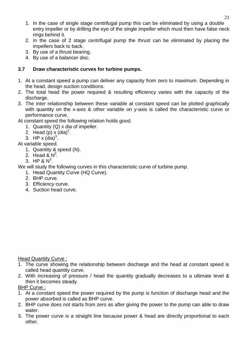
3.7 Draw characteristic curves for turbine pumps. 1. At a constant speed a pump can deliver any capacity from zero to maximum. Depending in
the head, design suction conditions. 2. The total head the power required & resulting efficiency varies with the capacity of the
discharge. 3. The inter relationship between these variable at constant speed can be plotted graphically
with quantity on the x-axis & other variable on y-axis is called the characteristic curve or performance curve.
At constant speed the following relation holds good. 1. Quantity (Q) x dia of impeller. 2. Head (p) x (dia)2. 3. HP x (dia)3.
At variable speed. 1. Quantity & speed (N). 2. Head & N2. 3. HP & N3.
We will study the following curves in this characteristic curve of turbine pump. 1. Head Quantity Curve (HQ Curve). 2. BHP curve. 3. Efficiency curve. 4. Suction head curve.
Head Quantity Curve : 1. The curve showing the relationship between discharge and the head at constant speed is
called head quantity curve. 2. With increasing of pressure / head the quantity gradually decreases to a ultimate level &
then it becomes steady. BHP Curve : 1. At a constant speed the power required by the pump is function of discharge head and the
power absorbed is called as BHP curve. 2. BHP curve does not starts from zero as after giving the power to the pump can able to draw
water. 3. The power curve is a straight line because power & head are directly proportional to each
other.
22
Efficiency Curve : 1. At a constant speed the efficiency is a function of discharge rate. The curve between two
variable is k/a the efficiency of discharge curve. 2. The efficiency curve raises from zero value to peak value & this gradually decreases in case
of a low specific speed pumps and sharply decreases in case of a high specific speed pump. 3. The mechanical efficiency is the ratio of water HP to BHP. 4. At the starting of the pump delivery valve is closed therefore discharge in zero, it means the
efficiency is zero. Suction Head Curve : 1. There are several factor which affect the suction difference. For Ex. Temp of the liquid,
viscously, density & attitude at which is carried out. 2. The suction lift varies inversely to the density of the liquid. Heavier is the liquid, suction lift is
radical. 3. The suction lift decreases as the temp of the liquid increases. Fitting attachment : Essential fittings : 1. Strainer : It is made up of cast iron and placed at the lower end of the suction pipe and main
function is to keep out the suspended solid in a sump. 2. Foot valve : It is non returned valve. It placed above the strainer & in the suction pipe. Its
main function is to prevent water from returning the sump. It is generally made up of cast iron or brass.
3. Main / Sluice valve / Gate valve : It is placed in the delivery column after the pumps outfit. Its main function is to allow the water to the delivery side when suction pipe is full of water.
4. Retaining valve : It is filled above the main valve to hold the water in the delivery column, when the pump stops. It is also a non returned valve.
5. Air cocks : air cocks are attached to all the valves used in a pump & of each jointing. 6. By pass valve : It is placed in delivery column & short circuling both the main valves
retaining valve. It enables the pump to be primed with water direct from the delivery column. Others fitting includes :
(a) A pressure gauge on delivery side to measure the delivery head.
23
(b) A vacuum gauge in suction side for indicating the suction head. (c) A hydraulic balancing disc is to counteract the end thrust.
Pressure gauge : A pressure gauge is attach to the delivery side for measurement of the head developed in the delivery column. Vacuum gauge : It measures the pressure in suction side of the pump. Balancing the end thrust : The axial end thrust of a pump must be balanced to ensure that the impeller revolve truly in their designed position with in the stages. In order to counter balance the end thrusts following method are adopted. (i) In single stage pumps use is made of a double entry which is systematic and thus produces
axial thrust. (ii) In single entry impeller is employed a thrust bearing is installed and relief holes are made in
the delivery side of impeller. (iii) In a two stage pump the thrust is eliminated by facing the impeller back.] (iv) In multi stage pumps hydraulic balancing device is provided. (v) In vertical pumps thrust ball bearing & ball and regular pivots are furnished and
symmetrically arrangement of impeller is used. The valves and fittings required with a centrifugal or turbine pumps are : 1. Strainer at the lower end of suction pipe to keep out plotting rubbish. 2. A foot valve above the strainer to prevent water retaining back from the pump & suction pipe
in to a sump. 3. A main valve also known as gets valve or switched valve in the delivery column. 4. A retaining valve above the main valve to hold water in the delivery column if the sumps stop
when the main valve is open. Axial and thrust : 1. The turbine pump, the area of the impeller expose towards suction side is less than that
expose towards delivery side. This results an end thrust develop by the high pressure from the outlet side towards inlet side of each impeller.
2. The axial end thrust accumulates because the impellers are in series. Therefore the shaft rotates out in axial end thrust.
In order to counter the axial end thrust methods adopted are : i. Use of double inlet impellers. ii. Hydraulic balancing disc or functional pad may be used. iii. Impeller may be grooved in two groups back to back with inlet opening of the impeller
in opposite direction. So that the axial thrust automatically balanced. Hydraulic balancing disc :
24
1. The hydraulic balancing disc is connected just at the delivery side & is keyed to the shaft.
2. High pressure water coming from the last impeller enters in a small scale or clearance between the disc.
3. At the disc is fixed to the shaft the pushing up the disc. Forces the shaft to move existing towards delivery side by which the balancing disc counteract the shifting of the shaft towards suction side disc to normal pressure of the water.
4. The movement of water from the clearance the disc and the seed closed up automatically when the thrust is balanced.
Mono Pump : Applicability condition :
1. Mono pump is generally used for small capacity & low heads. 2. It is especially used in muddy water in advancing deep headings. 3. In coal washers. 4. The radial cross section is circular & eccentric into the axis.
Construction :
1. It consists of a single helical motor within a rubber starter of double internal tulics. 2. The radial cross section is circular & eccentric to the axis. 3. The rotor given eccentric motion through the hollow structure of the pump. 4. Suction & delivery branches are within the main structure of the pump.
Principle of operation :
1. The mono pump has a screw like action. 2. The starter has half of the pitch of that of rotor. 3. With the stationery starter & a constant seal is maintain which advance forward from the
suction side to delivery side. 4. The amount of liquid within the seal continuous move forward due to positive
displacement of pump. Limitation :
1. The speed of rotation should within 960 rpm. To 1450 rpm. 2. Higher will be the speed greater will be the vibration. 3. The particle to be pumped must be sufficiently small to pass through the seal. 4. The delivery pipe dia. should be small so that high velocity can be obtained in main
delivery. Advantages :
1. The action is positive & displacement is continue act without pulsations. 2. Self priming is an in banal feature since these are no valves to give rise to steam &
leakage. 3. The pump can work efficiently with suction lifts of up 7.5 mts.
25
4. The pumps can readily dill with unit with serials damage to the starter or motor. 5. It is light & portable & maintenance is cheap.
Disadvantages :
1. Available heads are limited being in region of 45m & 90m for single & two stage model. 2. If the pump runs dry the starter will immediately be damaged. The pump most be first be
fell of with water for lubrication purpose the pipes & connected. 3. Large sites of solid particles present water of internal into the helical space may cause
forming motor & the starter. Bore hole pump : A pump which is used in a borehole of a couple of cm diameter is called as borehole pump. It is nothing but a multi stage turbine pump having with non over loading characteristics. Applicability condition :
1. In deep wells with the 200mt. borehole pump is suitable. 2. It is suitable for driving and shaft. 3. In washers borehole pump is used. 4. Borehole pump is used, where several logs of HP is required. 5. In shortage of electrical energy borehole pump is a suitable option.
Construction : Essentially it consist of 2 parts, one at the surface and the other inside the borehole. 1. The motor is placed in the surface & driving the pump through along driving shaft and lower
the pump unit is placed. 2. In the top part the motor is spindle connected through a thrust bearing to the shaft. 3. This also contains first discharge bend of rising men where the driving shaft inters the rising
man. The lower part along with suction pipe with strainer is suspended from the rising men the rising column.
The rising column is supported by intermediate guide bearing.
Impellers diffusers of pump are usually bronze.
In this pump a strainer is attached at the end and there is no foot valve. 3.9 Describe constructional features and working principle & use of rotor pump. (screw pump) Constructional features of rotor (screw) pump : This type of pump differs from the reciprocating and turbine pumps in its construction and working principle. It is a special type of electrically driven valve less, rotative pump which is inherently self priming with a lift (suction head) of up to 8m of water. It consists of essentially.
26
1. A rubber starter which has the form of a double internal helix and is a push fit in the machined cast iron barel. The starter may be of natural or synthetic rubber or of hypalon, viton or other plastic material.
2. A single helical rotor of special abrasion resisting or non corroding steel (monel metal or stainless steel).
3. Suction and delivery branches, ranging from 19mm to 75mm diameter. 4. Hollow driving shaft, running in ball bearing and transmitting an eccentric motion to the rotor
by a coupling rod of high tensile steel. The pump requires no foundation and will work on any gradient and even when placed vertical. Working principle of rotor (screw) pump : It is an eccentric screw pump. The radial cross section of the rotor is circular and is at all points eccentric to the axis, the centers of the sections lying along a helix whose axis forms the axis of the rotor. The pitch of the starter is twice that of the rotor and the two engage in such a fashion that the rotor section travels back and forth across the starter passage. The rotor maintains a constant seal across the starter. Whilst the rotor rotates in the starter, cavity formed between the two progresses from suction to delivery side resulting in uniform metered flow of water. The rotary motion creates an exceptionally high suction which exhausts all air from intake line resulting in immediate lift of water without need for priming. Water which enters the suction branch is thus caught up in the space between the rotor and starter and is forced through the pump as the rotor revolves. A positive pressure is developed on the delivery side and there must be a free passage for the water before the pump is started up. The rotor pump is normally direct driven by a three phase. A.C. quirrel cage induction motor running at 580, 720, 960 or 1450 revs. per minute. The motor is switched direct on to the line. The pumps are available as single stage pumps (0.33 to 10 H.P. of motor) or double stage pumps (10 to 20 H.P. of motor). Uses of rotor (screw) pumps : 1. The pump must never be run in a dry condition, or the starter will be immediately damaged.
The pump must first be filled with water for lubrication purposes before the pipes are connected. Thereafter, when the pump is stopped, sufficient liquid is normally trapped in the pump to provide lubrication on starting again.
2. When the delivery head exceeds about 30m a hand controlled valve, with a pipe leading back to the sump should be provided below the non return valve in the delivery pipe in order to relieve the pressure developed when the pump starts up against a full delivery column.
Coal plough : The machine is employed non cycle long wall face with a prop free front. A plough is a machine which is mounted on armoured chain convey or & cut a slice of 100mm to 200mm from the entire working height the seam during its travels along the face. The cut coal is loaded on the conveyor by a role which is built in part of the plough & which follows the cutting teeth. The seam thickness suitable for its operation is from 0.6mtr. The plough consists of 4 or more teeth two nearly vertical planes, fixed to base plate which is mounted on armoured chain conveyor and driven by the motor is usually is at the haulage end off the conveyor having chain pull the plough up or down the face & is treated through 115mm dia tube attached to the conveyor all along the face. The two ends of the chain passes over the two sprocket one at each end of the conveyor & are finally act the thin of coal during travel is either direction.
27
Valves required for turbine pump : In turbine pump a no. of external controlling valves are needed for convenient operation. Such valves are: (i) Foot valve in suction pipe. (ii) Retaining valve in delivery pipe. (iii) Main valve in delivery pipe. (iv) By pass valve for priming purpose. (v) Water sealed regulated valve. Total head of a pump : In case of suction lift it is the sum of the suction lift and discharge head which is in the case of positive suction head. It is the difference of the discharge head and the suction head. Different uses of compressed air in mines : Mining is basically situated in a remote place therefore energy required for drilling, blasting and transporting is unconvinced due to electric energy. Therefore we used compressed air which consists of into kinetic energy as a result of which different mining operations can be conducted. In mines different machineries are bored on compressed air like jack hammer. Down the hole drill dumpers power support pushing ram etc. Radial velocity of water : In centrifugal pump when the impellers move the water poured in a casing have two velocity. One in tangential & other is radial. The arrangement of speed which impeller the water in radial direction is k/a radial velocity of water. Why strainer used in pump : It is fitted at the inlet and end of the function pipe ranges to segregate out any solid particles mixed with water. Road header : the road header is a piece of heavy excavation equipment that utilize special cutting that mounted on the end of a boom that can swing upon down, left or right. Surface miner : Surface miner are heading machine which combining the operations of cutting coal or soft rock and loading simultaneously into mine cars, shuttle cars or conveyors without the usual unproductive breaks that are inherent in the convenient mining which follows a definite cycle of operations. Shovel : A shovel is a equipment which excavates the rocks or ore by digging from its operating base towards and dump it either on an dumper or railway wagon or over the spoil dump. It is used for remove over burden. Pipe joint : When pump have to deliver water in long distance there may be bends & lengthening of the pipes therefore different pipe joints are made during manufacturing or during jointing. The different pipe joints are: (i) Loose flange joints. (ii) Unicone joint. (iii) Spigot & faucal joint. (iv) Expansion joint. Gathering arm loader : A mechanical for loading loose rocks or coal has a tractor mounted chassis & carries a chain conveyor whose front end is drill into a wage shaped blades. It consists of 3 principle units: (i) A gathering head. (ii) A central crawler mounted chassis. (iii) A rear boom or jib. Bore hole pump : Bore hole pumps are multi stage turbine pump used to deliver water from bore holes wells or shafts from depths ranging up to as much as 200m or more. Such pumps may be of two types. (i) shaft driven bore hole pump. (ii) Submersible pump. Impeller : Impeller are made up of bronze or cast steel which when rotate around a shaft inside the casing is capable if converting the power energy of water to kinetic energy so that it can
28
deliver in case of centrifugal or turbine pumps monel metals can be use for it to crack it corrosive resistance. Flanges : Flanges are made up of mild steel subjected to heavy to heavy pressure. Flanges makes the pipe joint waterproof or joint leak proof. It is basically down during manufacturing time. Main unit of a dumper : The main unit are : (i) The power engine- The engine of any trucks system should be of higher power & lower in weight. (ii) The drive system- It is the system which supplies power from the engine to the wheels. Application of bucket wheel excavator : (i) It can be used for selective & then seam mining. (ii) Hard & tough well fragmented blasted rock with near boulders having consistency of uniform ground & bank condition. (iii) For reclamation of land. Application of shovel : It can be used in steep mining removal of OB in the counter mining in the hilly terrain. OB removal in open pit mining system, excavation in the face & loading on to trucks, removal of top soil, construction of roads and haul roads. Selection of a shovel is done by considering the following factors : (i) Requirement of duty production. (ii) Types & quality of the material to be excavated. (iii) Bucket fill factor (larger shovel dig better than the small one). (iv) Swell factor, working cycle time. Types of pump used in mines : There are various types of pumps commonly used in mines are : (i) Reciprocating pump. (ii) Centrifugal or rotary type pump (borehole pump, submersible pump, sinking pump). (iii) Mono pump. (iv) Megator pump. (v) Air lift pump. Rotor pump : A rotor pump (mono pump) basically operated on securing action. It is basically a single eccentric screw pump. Rotor pump are very efficient compare to centrifugal pump where high fluctuation of discharge of water is neated. Centrifugal pump : It consist of valve casing inside of which an impeller is incorporated mountain over a steel shaft. The ends of steel shaft passes through the casing & staffing boxes are provided there to seal water. Sinking pump : during the shaft sinking process specially designed sinking pumps are employed eject to pump, air lift, reciprocating or turbine pump may be employed for the purpose. Capacity of shovel : during the calculation of capacity of a shovel this following points are taken into accounting: (i) spotting time of dumper. (ii) Dumping time. (iii) Cycle time of a dumper. Road grader : this is a machine for leveling the road, surface by smoothening out the ups & down and for a cutting aside the boulder on the road. It is always pneumatic tyre mounted with any rear wheel drive & the front wheel are small. Jack hammer drill : It is a compressed air operated drill to which air is supplied from external compressors through hose pipes at pressure about 6kgf/cm2. The drill weights 15 to 25 kgf & drill holes of dia. 30mm to 38mm up to 2m depth. SDL : Side discharge loader. Its bucket capacity 6m3.
29
Dozer : A bulldozer is often f\referred to simplify as a dozer. It is a factor with a pusher blades attached to the font portion. A dozer can dig 1.2m to 1.5m below ground in earth or weathered rock. Scraper :This machine is diesel operated with pneumatic tyred wheels and has at the centre a bowl fitted with a cutting blade at bottom. The blade is reversible & can be replaced when blunt, its blade cuts a thin slice of earth usually between 75mm and 225mm thick 30m. Strainer : A strainer is situated at the lower end of the suction pipe. it keeps out the floating rubbish from the suction pipe. it also helps in merging the suction pipe end below the water level. Foot valve : It is a single by pass valve situated just above the strainer to prevent the water to reforming back from the pump towards the sump. Main valve / sluice valve / gate valve : A main valve is also known as gate valve or sluice valve. It is situated in delivery column and allow the water to pass through delivery pipe when the pups emerges sufficient water pressure. Retaining valve : A retaining valve is just placed above the main valve in the delivery column. It holds the water in the delivery column of the pump stops when the main valve is open. By pass valve : The by pass valve by passing the main & maintaining valve to enable the pump to be primed with water from the delivery column before starting off. Air cocks : It is used one on each stage to receive the air from the pump when priming & leakage. Hydraulic balancing disc : It is the device to counteract the end thrust. Pressure gauge : The pressure gauge is provided in the delivery column to indicate the delivery head developed by a pump. Vacuum gauge : A vacuum gauge is provided in the suction brake to indicate the suction leaf. Priming : If the pump barrel is fitted with air the pump can not creates its own vacuum when it is started & it facts to draw water. The difficulties may be overcoming by first filling the barrel with water by a process named as priming. Centrifugal and turbine pump most always priming before starting. Water hammer : It is a violent shock cause by a moving column of water when being suddenly brought to rest. In reciprocating pump it is liable occur when ever the piston returns into a half empty casing. The causes of water hammer. (i) When a suction pipe is too short or small. (ii) When a valve is effective. (iii) When the valve seal is defective. Cavitation : If a ram or piston is too fast the water can not enter the cylinder quickly so forming a vacuum in the barrel. In the next stock the water over takes the ram as it is throwing down and silver knock is setup this phenomenon is known as cavitation. Under what condition we use dragline : Generally the dragline are used for direct handling and re handling of OB material during over costing since it is cheapest means of OB removal. It is also used to handling soft and un-consolidate material, blast rock or mineral, coal, topsoil etc.
30
Intrinsically safe apparatus : Intrinsically safe as applied to apparatus or associated circuits shall denote that any sparking that may occur in normal working is capable of causing explosion of inflammable gas or vapour. Flame proof enclosure : Flame proof enclosure means an enclosure for electrical machinery and apparatus that will withstand when the covers or the other access doors are properly secured an internal explosion if the inflammable gas or vapour which may enter or originate inside the enclosure without suffering damage & without communicating the internal flammation to the external inflammable gas or vapour in which its designated to be used through any joints or other structural opening in the enclosure. Axial thrust : In multi stage turbine pump & centrifugal pump an end thrust is developed during the operation of the pump which acts axially upon the rotors towards the suction end. This is occurs as water under pressure leaks into a clearance space on both side of each impeller. The end thrust accumulates in a multi stage turbine pump as the impellers are skilled kept to the to one same shaft in a series. Toe : The lower side of t\a face of bench along its length is known as toe line & the various points on this line is known as toe. Berm : Piles of broken rock material & constructed along the crest to improve mine safety is called the berm. It acts as a guard rail to prevent trucks & other inolines from backing over or rest broken rock boulders control noise. Pumps : These are one of the most vital equipment for dewatering purpose both in the surface and in underground mining system. Piston pump : These are suitable only for pumping fairly clean water to intermediate height up to about 90mt to 120mt. the have merit of being light cheap. Boom : It is a lattice structural extension part of the dragline. It is made up of light iron teeth. Teeth : These are sharp nail to like structure fitted with the bucket. Bucket : It is a made up of mild steel. It hangs from the boom by means of cable its capacity varies according to the size of boom of a dragline. Boom angle : It is an angle made by the boom with the horizontal. It is generally varies from 20° - 30°. Working height : It is the height from the pulley to the surface at which the bucket, it lying or kept in rest position. It is denoted by d. Digging length : It is the length up to which the dragline can efficiency work below the surface. Dragline : A dragline is a machine used for excavating earth, sand or soft rock and consist essentially of a revolving deck a long light boom, crawler chains and a special type of bucket held in position and controlled by cables. Air excavator : It is a machine which excavates the rock or earth and swing or transport it within narrow limits to as adjacent place or dumps it on to a receptacle like a dumper, railway, wagons. Haul distance : It is the distance covered by the machine from working face to dumping point.
31
Basic principle of electric coal drill : The drill used for drilling holes in coal & similar soft rock is electrically operated & is of rotary type. Coal drill is not only used for caol but other rocks in coal mines expect very hard grades of stone. Why bucket wheel excavator is not used in hard ground : The bucket wheel excavator is suitable for soft rock and ground therefore it can not be used in strong ground. Why dumpers are widely used in multi seam opencast mining : dumpers are widely used in multi seam opencast mining for dumping and quick transportation of wastage material. Main function of by pass valve : The main function of by pass valve to enable the pump to be primed warm water from the delivery column before starting up. Volute casing : The casing covering the impeller is designed in such a manner that the kinetic energy of water at the discharge & gradually converted into pressure energy and finally enters into delivery pipe ranges with high pressure by a little kinetic energy. Shaft : The shaft over which the impeller are mounted is connected to the driving unit (motor). It is made up of forged steel, stainless steel, monel metal etc. Bearing : The bearing housing are carried in rigidly constructed brattices, both ball & roller bearing are used at both drive and non drive end. Stuffing box : the stuffing box is provided with convention packed gland using lubricated cotton packing mechanical seals are also provided to seal the water from the volute casing is kinetic energy stuffing box. Ram pump : Ram pump are suitable when the pumping condition are more adherous because of dirty water high lead or combined. Turbine pump : Turbine pump is a specific type of centrifugal pump in which the rotating impeller is surrounded by a series of stationery guide passing or diffusing channel. These takes place of & serve the same purpose as a volute casing namely the transformation of kinetic energy to pressure. Casing : It is of cast iron or cast steel for high heads made in suction head. Together by bolts between the end cover which form the respectively the suction delivery charge. Cutting height : It a particular boom angle. It is vertical distance between where the shovel rest and the top most point of the bucket where the boom are at their full extended position. The dumping radious : At a particular boom angle it is the horizontal at distance between the vertical swing axis of the main body if the short and the vertical centre line of the backed when the boom are at their full extended position. The digging radious : It is a particular boom angle it is the maximum horizontal distance between the top of the bucket & vertical swing axis of the shovel. At higher boom angle the digging radious will be lower. Bucket fill factor : It is the ratio between the actual volume of the material inside the bucket in the volume of the bucket whole multiplied by 100. Mathematically: Actual volume of material inside the bucket Bucket fill factor = ---------------------------------------------------------------- x 100 Volume of bucket
Capacity 2.5 to 5m3.
32
Swell factor : It is the ratio of weight per unit volume of solid rock in the bench to the weight per unit volume of loose rock mass after blasting. Bucket factor : Where the fill ability is because of slope angle of the bench & also depends upon the size of the bucket & its design. It is determined by field observation & experience. Swing factor : The standard cycle time of a shovel is based on its 90° swing for leading the cycle time of a shovel will increase & decrease of angle of swing. Cycle time : It is the total time takes by the shovel to complete one full cycle of operation starting from the crowding operation in to the face. Swing dumping & again come back to the face for crowding operation.
Digging + loading + hoisting + dumping + swing back time. Air leg drill : where compressed air is the motive power for drills, air leg may be advantageously used to mount the compressed air drill. An air leg drill essentially along cylinder in which a piston is actuated by compressed air controlled valve which is also used to release the air pressure to lower the position. Dumper : These are heavy duty trucks with a container body of steel open at the top for receiving material loaded mechanically by dragline, shovel etc. All the dumpers are so arranged to lift the loaded body utilizing hydraulic pressure. L.H.D. (Load Haul Dumps) : LHD is a mining equipment that performs loading, hoisting & dumping are discharging block material. It combines the operation of loading machines & a shuttle car. Shearer loader : The shearer loader cuts coal & loads it into an armoured face conveyor on which it is mounted. The shearer is mounted on a fixed plate provided with bearing pads which rest on the A.F.C. Electric coal drill : The drill used for drilling holes in coal & similar soft rock is electrically operated and is of rotary type such drill manufactured by a few companies like NAMC. VOLTAS. Shaft driven bore holes pump : In these type the pump is suspended at the bottom of the delivery pipe in the bore hole & the driving motor is at ground level. The pump is being driven by a shaft which passes down the center of the delivery pipes. Submersible pump : In submersible pump the electric motor & the pump from one compact unit. The suction pipe is eliminated, but a strainer is placed between the motor & the pump. The pump self consists of a no. of impeller mounted in a shaft supported by bearing. Pipe : These are essential for conveying fluids as such they are indispensable to mining operation. Ex. Water supply. Drainage as well as for carrying compressed air requiring for drilling etc.