MINDRAY - basicamerican.combasicamerican.com/nosync/Documents/2560_Manual - PM-50 Pulse... ·...
40
MINDRAY ® PM-50 PULSE OXIMETER OPERATING MANUAL Important: Do not operate the PM-50 Pulse Oximeter without first reading and understanding this manual! Save this manual for future use. Federal Law (USA) restricts this device to sale by or on the order of a physician. This product should not be used unless the operator has been instructed by a qualified healthcare professional.
Transcript of MINDRAY - basicamerican.combasicamerican.com/nosync/Documents/2560_Manual - PM-50 Pulse... ·...

MINDRAY®
PM-50 Pulse OxiMeter OPeratiNG MaNual
important: Do not operate the PM-50 Pulse Oximeter without first reading and understanding this manual!
save this manual for future use.
Federal Law (USA) restricts this device to sale by or on the order of a physician. This product should not be used unless the operator has been instructed by a qualified healthcare professional.

� JB7401-INS-LABRevA07
CoNTeNTS
PReFACe ........................................................................................................................................................... 4The PURPoSe oF ThIS MANUAL........................................................................................................4The INTeNded AUdIeNCe oF ThIS MANUAL ...................................................................................4VeRSIoN INFoRMATIoN oF ThIS MANUAL .......................................................................................4ILLUSTRATIoNS ANd NAMeS oF ThIS MANUAL ..............................................................................4CoNVeNTIoNS oF ThIS MANUAL .......................................................................................................4
1 SAFeTy ....................................................................................................................................................... 4SAFeTy INFoRMATIoN ................................................................................................................................4dANgeRS ......................................................................................................................................................5WARNINgS ....................................................................................................................................................5CAUTIoNS .....................................................................................................................................................6NoTeS ............................................................................................................................................................6
eqUIPMeNT SyMBoLS .........................................................................................................................7Ce MARkINg ..........................................................................................................................................7
� geNeRAL .................................................................................................................................................... 8INTRodUCTIoN ............................................................................................................................................8
CoNTRAINdICATIoNS ..........................................................................................................................8FUNCTIoNS ...................................................................................................................................................8PM-50 APPeARANCe ...................................................................................................................................9
TABLe �-1: APPeARANCe deSCRIPTIoN, FRoNT ANd BACk PANeL ............................................9dISPLAyed INFoRMATIoN .......................................................................................................................10
TABLe �-� deSCRIPTIoN oF dISPLAyed INFoRMATIoN ..............................................................10BUTToN oPeRATIoN .................................................................................................................................11
PoWeR BUTToN..................................................................................................................................11BACkLIghT BUTToN ..........................................................................................................................11CoNFIRM Id BUTToN .........................................................................................................................11deLeTe Id BUTToN ............................................................................................................................11
3 INSTALLATIoN .......................................................................................................................................... 1�UNPACkINg ANd INSPeCTIoN ................................................................................................................1�INSTALL BATTeRIeS...................................................................................................................................1�PoWeR oN ..................................................................................................................................................13CoNNeCT SPo� SeNSoR ..........................................................................................................................13CoNNeCT CoMPUTeR ..............................................................................................................................13
4 MeASUReMeNT ....................................................................................................................................... 14MeASURINg PRINCIPLe ...........................................................................................................................14PReCAUTIoNS ............................................................................................................................................14MeASURINg STePS ...................................................................................................................................15
MeASUReMeNT, AdULT oR ChILd ...................................................................................................15MeASURINg LIMITATIoNS ........................................................................................................................16
INACCURATe MeASUReMeNTS MAy Be CAUSed By: ..................................................................16LoSS oF PULSe SIgNAL CAN oCCUR IN The FoLLoWINg SITUATIoNS: ..................................16
5 oTheR FUNCTIoNS ................................................................................................................................ 17dATA MANAgeMeNT ................................................................................................................................17
dATA SToRAge....................................................................................................................................17dATA AddINg .......................................................................................................................................18dATA PRoTeCTIoN .............................................................................................................................18dATA deLeTIoN ...................................................................................................................................18
MeSSAgeS ..................................................................................................................................................19TABLe 5-1 MeSSAgeS ........................................................................................................................19TABLe 5-� eRRoR MeSSAgeS ..........................................................................................................19
PoWeR MANAgeMeNT .............................................................................................................................�0BATTeRy deTeCTIoN .........................................................................................................................�0eNeRgy SAVINg ..................................................................................................................................�0

3JB7401-INS-LABRevA07
6 MAINTeNANCe ........................................................................................................................................ �1SySTeM CheCk .........................................................................................................................................�1CLeANINg ...................................................................................................................................................�1
dISINFeCTIoN .....................................................................................................................................��dISPoSAL ....................................................................................................................................................��
7 PULSe oxIMeTeR MANAgeMeNT SySTeM ........................................................................................ �3INSTALL ANd UNINSTALL .........................................................................................................................�3
INSTALL ................................................................................................................................................�3UNINSTALL ...........................................................................................................................................�4
MAIN INTeRFACe .......................................................................................................................................�4MeNU BAR ............................................................................................................................................�4TooL BAR .............................................................................................................................................�6TABLe 7-1 ShoRTCUT ICoNS ............................................................................................................�6dATA AReA ...........................................................................................................................................�7
FUNCTIoNS .................................................................................................................................................�7dATA oUTPUT ......................................................................................................................................�7SoFTWARe UPgRAde ........................................................................................................................�8FILe MANAgeMeNT ............................................................................................................................30ModIFy PATIeNT INFoRMATIoN .......................................................................................................31PRINT dATA ..........................................................................................................................................31PRoMPT MeSSAge .............................................................................................................................3�TABLe 7-� eRRoR PRoMPT MeSSAgeS ..........................................................................................3�
8 ACCeSSoRIeS ......................................................................................................................................... 33
9 SPeCIFICATIoNS ..................................................................................................................................... 34geNeRAL SPeCIFICATIoNS ......................................................................................................................34
BASICS ..................................................................................................................................................34SAFeTy deSIgNATIoNS (PeR IeC 60601-1 STANdARd) .................................................................34
dISPLAy ANd CoNTRoL ...........................................................................................................................34dISPLAy ................................................................................................................................................34BUTToNS ..............................................................................................................................................34PoWeR SAVINg FeATUReS ...............................................................................................................34CoNNeCToR ........................................................................................................................................34
eLeCTRICAL SPeCIFICATIoNS ................................................................................................................35PRINTINg.....................................................................................................................................................35PhySICAL ChARACTeRISTICS ................................................................................................................35eNVIRoNMeNT ANd SAFeTy ...................................................................................................................35
TeMPeRATURe ....................................................................................................................................35hUMIdITy .............................................................................................................................................35ALTITUde ..............................................................................................................................................35TRANSPoRTATIoN ..............................................................................................................................35ShoCk ..................................................................................................................................................35
10 LIMITed WARRANTy ............................................................................................................................... 36
11 INdex ........................................................................................................................................................ 37

4 JB7401-INS-LABRevA07
PReFACe
The Purpose of this ManualThis manual provides the instructions necessary to operate the PM-50 Pulse Oximeter (hereinafter called the PM-50) in accordance with its function and intended use. Obser-vance of this manual is a prerequisite for proper performance and correct operation, and ensures patient and operator safety.
This manual is an integral part of and should always be kept close to the your PM-50, so that it can be obtained conveniently when necessary.
The Intended Audience of this ManualThis manual is geared for the clinical medical professionals. Clinical medical profession-als are expected to have working knowledge of medical procedures, practices and termi-nology as required for monitoring patients.
Version Information of this ManualThis manual has a revision number. This revision number changes whenever the manual is updated due to software or technical specification change. Content of this manual is subject to change without prior notice. The revision information of this manual is print-ed at the bottom of every page.
Illustrations and Names of this ManualAll illustrations in this manual are provided as examples only. They may not necessarily concur with the graph, settings or data displayed on your PM-50.
Conventions of this ManualItalic text is used in this manual to quote the referenced chapters or sections.
The terms danger, warning, and caution are used throughout this manual to point out hazards and to designate a degree or level or seriousness (See next section 1 SAFETY).
1 SAFeTy
SAFeTy INFoRMATIoNThe safety statements presented in this chapter refer to the basic safety information that the operator of the PM-50 shall pay attention to and abide by. There are additional safety statements in other chapters or sections, which may be the same as or similar to the following, or specific to the operations.
dANgeR: Indicates an imminent hazard situation that, if not avoided, will result in death or serious injury.
WARNINg: Indicates a potential hazard situation or unsafe practice that, if not avoided, could result in death or serious injury.

5JB7401-INS-LABRevA07
CAUTIoN: Indicates a potential hazard or unsafe practice that, if not avoided, could result in minor personal injury or product/property damage.
Note:Providesapplicationrecommendationsorotherusefulinformationtoensurethatyougetthemostfromyourproduct.
dANgeRSThere are no dangers that refer to the product in general. Specific “Danger” statements may be given in the respective sections of this manual.
WARNINgS
WARNINg: Federal Law (USA) restricts this device to sale by or on the order of a physician.
WARNING: The PM-50 is intended for use by qualified clinical physicians or appropriately-trained nurses in a hospital setting.
WARNINg: The PM-50 is designed for real-time and rapid measurement of the patient’s Spo�. It is not suitable for long-time continuous patient monitoring. Continual measurement must not exceed � hours.
WARNINg: The PM-50 is intended only as an adjunct in patient assessment. It must be used in conjunction with clinical signs and symptoms. It is not intended as a device used for treatment purposes.
WARNINg: To ensure patient safety, verify that this device and its accessories can function safely and normally before use.
WARNING: EXPLOSION HAZARD: Do not use the PM-50 in the presence of flammable anesthetics, explosive substances, vapors or liquids.
WARNINg: Failure to implement a satisfactory maintenance schedule may cause undue device failure and possible health hazard.
WARNINg: When using the PM-50 with electrical surgery equipment, pay attention to and guarantee safety of the patient being measured.
WARNINg: do not pull or lift the PM-50 by its connection cable. That may lead to falling and consequent patient injuries.
WARNING: Magnetic and electrical fields are capable of interfering with the proper performance of the PM-50. For this reason, ensure that all external devices operated in the vicinity of the PM-50 comply with the relevant eMC requirements. Mobile phones, x-ray equipment and/or MRI devices are a possible source of interference, as they may emit high levels of electromagnetic radiation.
6 JB7401-INS-LABRevA07
WARNINg: The PM-50 and its accessories may be contaminated by microorganisms during transporting, use, and/or storage. Use the methods recommended in this manual to sterilize and disinfect the PM-50 and/or its accessories when the packing material is damaged, or it has not been used for a long time.
CAUTIoNS
CAUTIoN: The device should be appropriately placed. keep it from falling, strong vibration or other mechanical damage.
CAUTION: To ensure patient safety, use only parts and accessories specified in this manual.
CAUTIoN: The PM-50 is a commonly sealed device. keep its surface dry and clean, and prevent any liquid from infiltrating it.
CAUTIoN: do not use mobile phones near the PM-50 when it is in operation.
CAUTION: The PM-50 should be maintained only by qualified personnel.
CAUTIoN: Before using the PM-50 on patients, the user should be familiar with its operation.
NoTeS
Note:Important!Beforeuse,carefullyreadthismanual,allsafetyinformationandspecifications.
Note:Thisdeviceisnotintendedforhomeuse.
Note:ThisdevicecomplieswiththerequirementsofCISPR11(EN55011)classA.
7JB7401-INS-LABRevA07
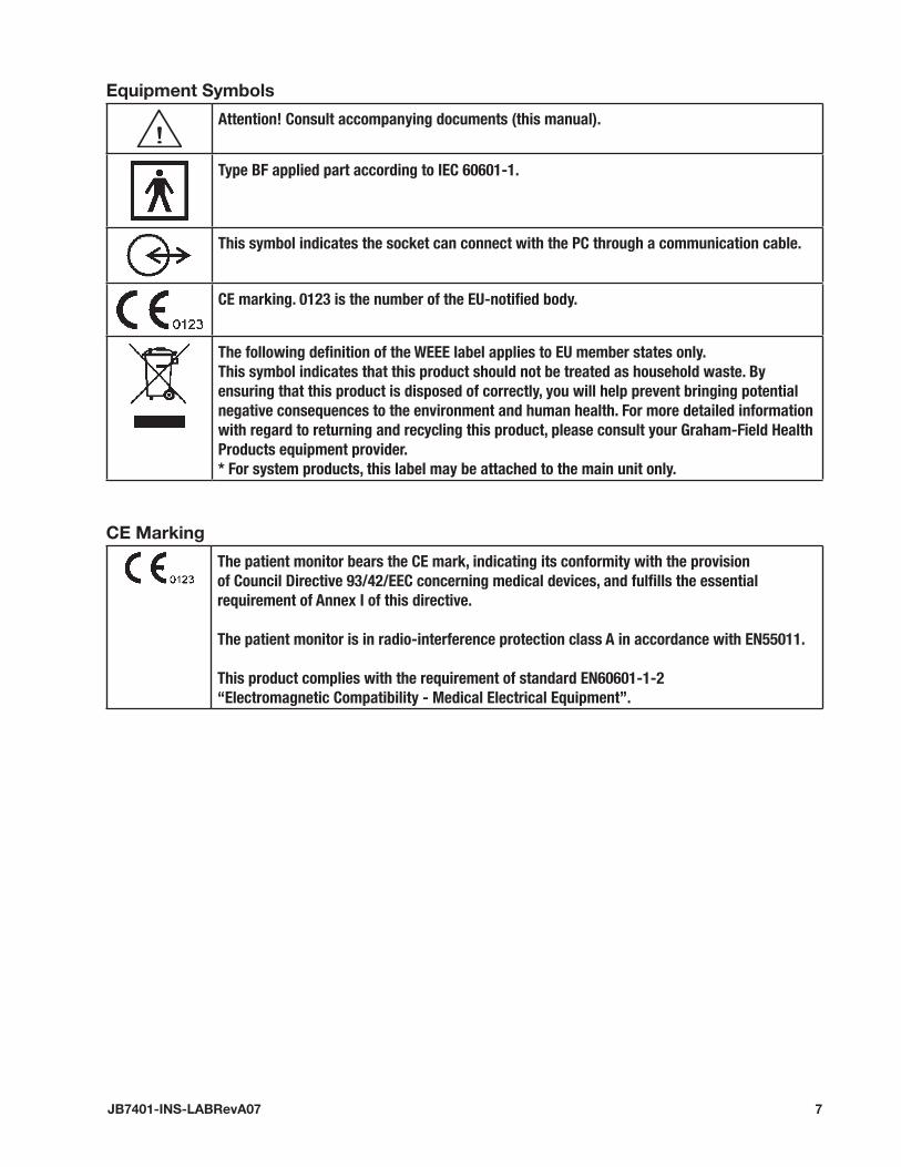
equipment Symbols
Attention! Consult accompanying documents (this manual).
Type BF applied part according to IEC 60601-1.
This symbol indicates the socket can connect with the PC through a communication cable.
CE marking. 0123 is the number of the EU-notified body.
The following definition of the WEEE label applies to EU member states only. This symbol indicates that this product should not be treated as household waste. By ensuring that this product is disposed of correctly, you will help prevent bringing potential negative consequences to the environment and human health. For more detailed information with regard to returning and recycling this product, please consult your Graham-Field Health Products equipment provider.* For system products, this label may be attached to the main unit only.
Ce Marking
The patient monitor bears the CE mark, indicating its conformity with the provision of Council Directive 93/42/EEC concerning medical devices, and fulfills the essential requirement of Annex I of this directive.
The patient monitor is in radio-interference protection class A in accordance with EN55011.
This product complies with the requirement of standard EN60601-1-2“Electromagnetic Compatibility - Medical Electrical Equipment”.
8 JB7401-INS-LABRevA07
� geNeRAL
INTRodUCTIoNThe PM-50 Pulse Oximeter is a noninvasive, spot-check, oxygen saturation and pulse rate monitor. It operates only on battery power using specified sensors labeled for patients ranging from infants to adults.
Parameters measured by the PM-50 include:
• Arterial oxygen saturation (SpO2)
• Pulse rate (PR)
• Pulse strength
The PM-50 measures these parameters with an SpO2 sensor and displays them on the LCD after certain further processing.
The PM-50 is operated and controlled by three buttons: the Power button, Backlight but-ton and Confirm ID button. The PM-50 is also capable of managing measured data and transmitting the patient’s trend, through the dual-purpose socket, to a PC for printing.
ContraindicationsNone
FUNCTIoNSThe PM-50 has the following functions:
• Measuring: SpO2, PR, and pulse strength.
• Prompting: Memory full, ID full, low battery, standby, and technical error etc.
• Power managing: automatic standby, automatic shutdown.
• Data Managing: data storage, data protection, data deletion.
• Data Printing: patient information and trend data.
For the data printing function, you must install the Pulse Oximeter management system on a PC equipped with a printer, and connect the PM-50 to the PC with a communication cable. For details, please refer to section 7 Pulse Oximeter Management System.

9JB7401-INS-LABRevA07
PM-50 APPeARANCe
Figure 2-1Front Panel
Figure 2-2Back Panel
1
2345678
Table �-1: Appearance description, Front and Back Panel
No. Description Remarks
1 Dual-purpose socket Connects SpO2 sensor or PC communication cable
2 LCD Displays information listed in Table 2-2
3 Power Turns the device on or off
4 Confirm ID Confirms the patient ID for current measurement
5 Delete ID A key combination of 4 and 6
6 Backlight Turns on or off the backlight
7 Caution - refer to this manual
8 Battery door Open it to install or remove batteries

10 JB7401-INS-LABRevA07
dISPLAyed INFoRMATIoNThe figure below shows information displayed on the PM-50’s LCD.
Figure 2-3Displayed Information
21
34
567
Table �-� description of displayed Information
No. Description Remarks
1 ID number Displays current ID number ranging from 000 to 100
2 ID Full Appears when ID≥95 and blinks when stored ID is being covered by new ID
3 Memory Full Appears when previous data is to be covered by new data. Please refer to 5.1.1 Data Storage
4 Pulse Strength Can display 7 segments at most to indicate real time pulse strength
5 SpO2 value Displays SpO2 value and is refreshed every second
6 PR value Displays PR value and is refreshed every second.Unit: bpm (beats/minute)
7 Low battery Appears only when the battery energy is low

11JB7401-INS-LABRevA07
BUTToN oPeRATIoNThere are three soft buttons, shown below, on the PM-50’s front panel.
Figure 2-4 ButtonsBacklight Confirm IDPower
Power Button• Power on: Press to turn on the device.
• Power off: Press and hold for two seconds to turn off the device.
Note:ThePM-50ispoweredbybatteriesonly.Pleaseinstallbatteriesbeforeuseasdescribedinsection3, INSTALLATION, Install Batteries.
Note:IftheSpO2cablebecomesdisconnectedorthefingermovesawayfromthesensor,thePM-50willautomaticallyenterstandbymode.Inthismode,whenafingerisinsertedintothesensor,thePM-50willautomaticallyresumeoperationmode.Otherwise,ifnofingerisinsertedin5minutes,thePM-50willautomaticallyturnoff.
Backlight Button• Backlight on: Press the Backlight button to turn on backlight.
• Backlight off: Press the Backlight button to turn off backlight.
Confirm ID ButtonThe Confirm ID button is used to add data. It enables the user to add data, without using a new ID number, to a re-test for the same patient after the sensor is accidentally discon-nected.
Note:Refertosection5 OTHER FUNCTIONS, Data Managementfordetaileduseofthisbutton.
delete Id ButtonThe Delete ID button is a key combination of the Backlight button and the Confirm ID button.
Note:Refertosection5 OTHER FUNCTIONS, Data Managementfordetaileduseofthisbutton.

1� JB7401-INS-LABRevA07
3 INSTALLATIoN
UNPACkINg ANd INSPeCTIoNBefore unpacking, examine the packing case carefully for signs of damage. If you detect any damage, contact the carrier or our company.
If the packing case is intact, open the package and remove the device and accessories carefully. Check all materials against the packing list and check for any mechanical dam-age. Contact our Customer Service Department in case of any problem.
Note:Savethepackingcaseandpackagingmaterialforfuturetransportandstorage.
WARNINg: Be sure to keep the packaging materials from children’s reach.
WARNINg: disposal of the packaging materials in accordance with your local laws.
INSTALL BATTeRIeSThe PM-50 is powered by four batteries. Follow the steps below to install batteries be-fore use:
1. Hold the PM-50 in one hand.
2. Place the other hand on the battery cover.
3. Push the cover away as shown in Figure 3-1.
4. Place batteries in the slots per the + and - indications as shown in Figure 3-2.
5. Push back the battery cover.
Figure 3-1 Figure 3-2
CAUTIoN: dispose of the batteries in accordance with your local laws.
CAUTIoN: Use AA alkaline batteries or rechargeable batteries. do not use carbon or poor quality batteries. Remove the batteries if the device will not be used for a long time.
WARNINg: Always use charged batteries; abnormal power supply may lead to product damage or even personal injury.

13JB7401-INS-LABRevA07
PoWeR oNPress the Power button to turn on the PM-50. The startup interfaces and version infor-mation will be displayed; then the initialization interface, as shown in Figure 3-3, will be displayed. After that, the PM-50 will automatically switch to standby mode as shown in Figure 3-4.
Figure 3-3 Figure 3-4
CoNNeCT SPo� SeNSoRConnect the SpO2 sensor to the PM-50 by inserting the sensor’s connector in the PM-50’s dual-purpose socket, as shown below.
Figure 3-5Connect SpO2 sensor
CoNNeCT CoMPUTeRThe PM-50 can be connected to a Personal Computer with a communication cable, to transmit patient trend to the computer for printing.
Connect one end of the PC communication cable to the PM-50’s dual-purpose socket, and the other end to the PC’s serial port.
Figure 3-6Connect Symbol
The PM-50 will display the above symbol, indicating that the PM-50 has connected with the PC successfully.

14 JB7401-INS-LABRevA07
4 MeASUReMeNT
MeASURINg PRINCIPLeSpO2 monitoring is a non-invasive technique used to measure the amount of oxygenated hemoglobin and pulse rate by measuring the absorption of selected wavelengths of light. The light generated in the probe passes through the tissue and is converted into electri-cal signals by the photodetector in the probe. The PM-50 processes the electrical signal and displays digital values for SpO2 and pulse rate on the LCD. The displayed SpO2 value is of functional saturation.
The sensor measurement wavelengths are nominally 660nm for the red LED and 940nm for infrared LED. The maximum optical power output for LED is 4mW.
PReCAUTIoNS
Note:DonotperformSpO2monitoringandNIBPmeasurementsonthesamearmsimultaneously.ObstructionofbloodflowduringNIBPmeasurementsmayadverselyaffectthereadingoftheSpO2value.
Note:Ameasurementshalllastlongerthan15seconds.Otherwise,newdataofnextmeasurementcan’tbeaddedtothesamepatient.
Note:DonotusethePM-50forprolongedmonitoring.
WARNINg: Inspect the sensor cable before monitoring. do not use the Spo� sensor if the package or the sensor is damaged.
WARNINg: do not use the PM-50 to measure patients whose pulse rate is lower than �5bpm, which may cause incorrect results.
WARNINg: Remove the Spo� sensor from the patient immediately after measurement.
WARNINg: Route cables carefully to reduce the possibility of patient entanglement or strangulation. Cables of electrical surgical equipment should not be wound around that of the Spo� sensor.
WARNINg: do not put the sensor on extremities with arterial catheter or venous syringe.
WARNING: If no pulse is found or the reading is unreasonable, first check the patient’s condition, and then check the device and the Spo� sensor for proper function.
WARNINg: do not reuse disposable Spo� sensors.
WARNING: Ensure that no obstruction (contamination, scar tissue, acrylic fingernails, fingernail polish, etc.) exists at the site where the sensor is placed. Otherwise, the measured result may be incorrect because the signal received by the sensor is affected.

15JB7401-INS-LABRevA07
WARNINg: When used on different patients, the PM-50 is prone to cross-contamination, which should be prevented and controlled by the user. disinfect the Spo� sensor before use with other patients.
MeASURINg STePSSensor selection for SpO2 measurement depends on the patient type. For an adult pa-tient, choose a finger SpO2 sensor. Refer to the following procedures for adult and child measurement.
Measurement, Adult or ChildFollow the steps below to use the adult or child finger SpO2 sensor:
1. Select the appropriate sensor (adult or child) *.
*Note:Useadultsensorforpatientweighing>30kg(66lb.).Usechildsensorforchildweighing10-50kg(22-110lb.)
2. Insert the sensor’s connector in the PM-50’s dual-purpose socket.
3. Turn on the PM-50 to enter standby mode.
4. Attach the sensor to an appropriate site on the patient.
Figure 4-1 Placing the adult SpO2 Sensor
5. The readings will be displayed on the PM-50’s LCD a moment later.
Note:PlacetheSpO2sensorcableatthebacksideofthepatienthand.Ensurethatthefingernailisjustoppositetothelightemittedfromthesensor.
Note:Toacquireaccurateresults,pleasereaddatauntilthesensorissteadilyplaced.
Note:Readingsmaynotbeaccuratewheneitherthesensororthepatientismoving.

16 JB7401-INS-LABRevA07
MeASURINg LIMITATIoNSIf the accuracy of any measurement does not seem reasonable, first check the patient’s vital signs using an alternate method, then check the device for proper function.
Inaccurate measurements may be caused by:• Incorrect sensor application or use.
• Significant levels of dysfunctional hemoglobins (e.g., carboxyhemoglobin or methe-moglobin).
• Intravascular dyes such as indocyanine green or methylene blue.
• Exposure to excessive illumination, such as surgical lamps (especially ones with a xe-non light source), bilirubin lamps, fluorescent lights, infrared heating lamps, or direct sunlight (exposure to excessive illumination can be corrected by covering the sensor with a dark material).
• Excessive patient motion.
• Venous pulsations.
• Placement of a sensor on the same extremity with a blood pressure cuff, arterial cath-eter, or intravascular line.
• Acrylic fingernails and/or dark fingernail polish.
Loss of pulse signal can occur in the following situations:• The sensor is too tight.
• There is excessive illumination from light sources such as a surgical lamp, a bilirubin lamp, or sunlight.
• A blood pressure cuff is inflated on the same extremity as the one with a SpO2 sensor attached.
• The patient has hypotension, severe vasoconstriction, severe anemia, or hypother-mia.
• There is arterial occlusion proximal to the sensor.
• The patient is in cardiac arrest or shock.

17JB7401-INS-LABRevA07
5 oTheR FUNCTIoNS
dATA MANAgeMeNT
data StorageThe PM-50 oximeter has internal memory to store data. The memory is divided into the ID Data Zone and the Trend Data Zone.
The ID Data Zone is capable of storing 100 patients’ ID data (ID, as shown below) at most. When the number exceeds 100, new data will automatically overwrite the oldest data.
ID001 data ID002 data ID003 data …… ID100 data
One ID data includes:
• Number of the SpO2 and pulse rate values stored to this ID.
• Maximum SpO2 value of this ID.
• Minimum SpO2 value of this ID.
• Average SpO2 value of this ID.
• Maximum PR value of this ID.
• Minimum PR value of this ID.
• Average PR value of this ID.
The Trend Data Zone is capable of storing 200 trend data (TD, as shown below) at most. When the number exceeds 200, new data will automatically overwrite the oldest data.
TD 001 TD 002 TD 003 …… TD 200
The first trend data will be stored 15 seconds after the pulse is found. Thereafter one trend data will be stored every 2 minutes. One trend data includes:
• Average SpO2 value within the 2 minutes.
• Average PR value within the 2 minutes.
Note:ThefirsttrenddataaretheinstantvaluesofSpO2andPR.
Note:Apatient’sIDdataarecalculatedfromallmeasuredtrenddataofthatpatient.
Note:Oncethetrenddataofapatientiscovered,alltrenddataofthatpatientwillbedeleted;however,theIDdatawillnotbedeleted.

18 JB7401-INS-LABRevA07
data AddingThe previously stored ID number appears on the LCD when a finger is inserted into the SpO2 sensor. It will keep blinking for 8 seconds after the pulse is found.
• Press the Confirm ID button before the ID number stops blinking; the PM-50 will set the ID number as current patient ID. The data measured thereafter will be superadd-ed to the previous ID.
• If the user doesn’t press the Confirm ID button before the ID number stops blinking, a new ID number, which is the blinking number plus 1, will be set as the current patient ID.
The Confirm ID button is of no use when the current ID number is 000, which will auto-matically change to 001 when the pulse is found.
data ProtectionThe PM-50 has data protection function. When the power is turned off accidentally dur-ing the process of storing a data, the PM-50 will evaluate completeness of the last stored data when it is turned back on. If the data is complete, it will be validated; otherwise it will be invalidated.
data deletionPress the Delete ID button in standby mode; the message DELETE ALL? will be displayed as shown in Figure 5 1.
Figure 5-1 Figure 5-2
• To delete all stored data: Press the Delete ID button again. As shown in Figure 5-2, the message ALL DELETED will be displayed for 2 seconds. The PM-50 will then switch back to standby mode, the ID number will restore to 000, and the Memory Full and ID Full symbols will disappear.
• To not delete all stored data: Do not press the Delete ID button; wait for 10 seconds. The DELETE ALL? message will disappear automatically and the previous operation will be cancelled. The PM-50 will then switch back to the previous mode.

19JB7401-INS-LABRevA07
MeSSAgeSThe PM-50 can display various messages. Table 5-1 lists messages with their causes and solutions.
Table 5-1 Messages
Message Cause Solution
Low Battery Battery energy lower than 4.0 Voltage Replace batteries in time
Memory Full The internal memory is almost full Stored data is to be covered. Export data in time.
Blinking “Memory Full”
Memory is full Stored data is being covered. Export data in time.
ID Full ID number Stored is greater than 95. ID data is to be covered. Export data in time.
Blinking “ID Full” ID data is being covered. Export data in time.
Standby The device is in standby mode. None.
Communication The device is in communication mode. None.
DELETE ALL? The Delete ID button is pressed. Refer to previous Data Deletion
ALL DELETED The Delete ID button is pressed again after “DELETE ALL?” appears.
None.
The PM-50 can also display technical error messages. Table 5-2 lists error messages with their causes and solutions.
If the LCD can’t display anything, it may be damaged, or error occurs during system self-test. Please turn off the device (if you can’t turn it off, remove the batteries) and contact our Customer Service.
Table 5-� error messages
Error Message Cause Solution
Initiate Error Failed self-test Turn off the device (if can’t, remove the batteries) and contact us for service.
Please Release the Button
Button error Check for jammed button. If problem remains, contact us for service.
Pulse Not Found Searching…
Pulse not found Check the patient and alert the doctor.

�0 JB7401-INS-LABRevA07
PoWeR MANAgeMeNT
Battery detectionThe PM-50 can detect the battery energy and
• display Low Battery message when battery voltage is less than 4.0 V.
• turn off the device automatically when battery voltage is less than 3.85V.
energy SavingThe PM-50 can save battery energy by
• switching to standby mode automatically when the finger disconnects from the sen-sor or the sensor disconnects from the PM-50.
• turning off automatically if no finger is inserted into the sensor within 5 minutes in standby mode.
Note:ThePM-50willautomaticallyswitchfromstandbymodetooperationmodewhenafingerisinsertedintothesensor.
Note:IfyourPM-50hasbeenprovidedwithPMSsoftware,refertosection7 Pulse Oximeter Management Systemformorefunctions.

�1JB7401-INS-LABRevA07
6 MAINTeNANCe
SySTeM CheCkTo ensure the safe operation of the PM-50, ensure that your qualified service personnel have performed a complete inspection before operating the PM-50, after service or sys-tem upgrade, or after the PM-50 has been used for six consecutive months.
Before using the PM-50, perform the following steps.
1. Check the PM-50 for mechanical damage.
2. Check all cables and accessories for damage.
3. Check all functions of the PM-50 to ensure that it is in proper operating condition.
In case of any damage or exception, do not use the PM-50. Contact your hospital techni-cian or our Customer Service immediately.
WARNINg: Failure on the part of the responsible hospital or institution using the PM-50 to implement a satisfactory maintenance schedule may cause device failure and health hazard.
WARNINg: The safety inspection or maintenance, which requires opening the monitor housing, must be performed by trained, authorized personnel only. otherwise, device failure and health hazard may occur.
CLeANINgClean the PM-50 regularly. If there is pollution, dust or sand in your environment, the PM-50 should be cleaned more frequently. Before cleaning the PM-50, consult your hospi-tal’s regulations.
Cleaning agents:
• Mild soap and water
• Quaternary ammonia
• Water/bleach solution (100:1)
• 3 vol% Hydrogen peroxide in water solution
• 70 vol% isopropyl or ethyl alcohol
1. Power off the oximeter.
2. Wipe the surface and LCD lens with a cotton swab moistened with a cleaning agent.
3. Wipe the oximeter case with a soft cloth dampened with a cleaning agent.
CAUTIoN: do not allow liquid to enter the sensor connector.
�� JB7401-INS-LABRevA07
To avoid damage to the device, follow these rules:
CAUTIoN: ALWAyS dilute the agents according to the manufacturer’s suggestions.
CAUTIoN: ALWAyS wipe off excessive cleaning agent with a dry cloth after cleaning.
CAUTIoN: NeVeR submerge the device in water or any cleaning agent, or pour or spray water or any cleaning agent on the device.
CAUTION: NEVER permit fluids to run into the casing, switches, connectors, or any ventilation openings in the device.
CAUTIoN: NeVeR use abrasive, erosive cleaners, or cleaners containing acetone.
CAUTIoN: Failure to follow these rules may erode and/or fray the casing, blur lettering on the labels, and/or cause device failure.
For cleaning information of accessories, please refer to the accessory instructions.
disinfection
CAUTIoN: disinfection may cause damage to the device.
We recommend the disinfection be performed only when necessary. The device should be cleaned prior to disinfection.
Recommended disinfection material: Alcohol based (Ethanol 70%, Isopropanol 70%), and aldehyde based.
WARNINg: Never use ethylene oxide and formaldehyde to disinfect.
WARNINg: The cleaning agents above can only be used for general cleaning. If you use them to control infections, we shall assume no responsibility for the effectiveness.
CAUTIoN: do not autoclave, pressure sterilize, or gas sterilize the oximeter.
CAUTIoN: disinfection may cause damage to the device; therefore, when preparing to disinfect the device, consult your hospital’s infection controllers or professionals.
dISPoSALTo avoid contaminating or infecting personnel, the environment, or other equipment, ensure that you disinfect or decontaminate the device appropriately before disposing of it in accordance with federal and local law for equipment containing electrical and electronic parts. When disposing of the SpO2 sensor, follow local regulations regarding disposal of hospital waste.

�3JB7401-INS-LABRevA07
7 PULSe oxIMeTeR MANAgeMeNT SySTeMThe optional Pulse Oximeter Management System software (PMS software) was devel-oped to achieve more functions with the PM-50. The PMS software runs in (English) Windows 98/2000/XP operating system. In conjunction with the internal software of the PM-50, the following functions can be achieved.
• Outputting data and upgrading internal software
• Previewing exported data
• Adding patient information
• Printing patient data
INSTALL ANd UNINSTALLBefore you use PMS software, you must first install it on your PC. The following Install and Uninstall sections are provided as examples for Windows 2000 operating system.
InstallTo install the PMS software:
1. Insert the installation CD into the CD-ROM.
2. Run the file Setup.exe in the installation CD (symbol shown below).
Figure 7-1
3. Choose your favorite language according to the prompt. Click OK, and then click Next in the next dialog box.
4. Input the correct serial number, and click Next to resume.
5. Select the serial port to connect the PM-50 Pulse Oximeter with your PC, and click Next to resume.
6. Choose the destination folder where the PMS software is to be installed.
7. Click Next and Finish according to the prompt.
8. After the installation is complete, a new shortcut icon will appear in the desktop of your computer as shown below.
Figure 7-2
9. Double click the icon to run the PMS software.

�4 JB7401-INS-LABRevA07
UninstallTo uninstall the PMS software:
1. Click Start-Setting-Control Panel, and double click the Add/Remove Programs icon to open the Add/Remove Programs dialog box.
2. Select Pulse Oximeter Management System, and click Change/Remove. Then follow the prompt to uninstall the PMS software.
Note:Theprecedingstepsareprovidedasexamplesonly.Yoursmaybeslightlydifferent,dependingonyouroperatingsystem.
MAIN INTeRFACeDouble click the shortcut icon for PMS software on the desktop of your computer; the PMS software Main Interface will be displayed as shown below.
Figure 7-3
12
33
1 Menu Bar 2 Tool Bar 3 Data Area
Menu BarFour menus are available In the Menu Bar: File, Setup, Operation, and Help. Descrip-tions follow.
File: Click the File menu to see its pull-down menu as shown below.
Figure 7-4 File Menu

�5JB7401-INS-LABRevA07
The File menu has five submenus:
• File Management: Click to open the File Management dialog box.
• Print: Click to print the current patient data.
• Print Preview: Click to preview the data to be printed.
• Print Setting: Click to open the Print Setting dialog box.
• Exit: Click to exit the PMS software.
Setup: Click the Setup menu to see its pull-down menu as shown below.
Figure 7-5 Setup Menu
The Setup menu has two submenus:
• Patient Information: Click to open the Modify Patient Information dialog box.
• Serial Port Selection: Click to open the Serial Port Selection dialog box.
When you use the Data Output or Software Upgrade function, the default serial port may be occupied. At this time, you can click the Serial Port Selection menu, shown be-low, to select another serial port.
Figure 7-6
Operation: Click the Operation menu to see its pull-down menu, shown below.
Figure 7-7
The Operation menu has two submenus:
• Data Output: Click to conduct the Data Output function.
• Software Upgrade: Click to open the Input Password dialog box.

�6 JB7401-INS-LABRevA07
Help: Click the Help menu to see its pull-down menu, shown below.
Figure 7-8 Help Menu
The Help menu has two submenus:
• Help: Click to open the Help document.
• About PMS: Click to show the copyright information.
Note:WhenyouopentheHelpdocument,ifadialogboxpopsupandtellsyoutoinstalllanguagepack,selectNever install any language packs,andthenclickCancel.
Tool BarIn the tool bar you can see the following shortcut icons, explained below.
Figure 7-9 Shortcut Icons
Table 7-1 Shortcut Icons
Icon Icon Name Description
File Management Shortcut to File Management submenu
Print Shortcut to Print submenu
Print Preview Shortcut to Print Preview submenu
Serial Port Selection Shortcut to Serial Port Selection submenu
Patient Information Shortcut to Patient Information submenu
Data Output Shortcut to Data Output submenu
Help Shortcut to Help submenu

�7JB7401-INS-LABRevA07
data AreaThe Data Area displays the data of the current ID. The left part of the Data Area is the Information Area, and the right part is the Patient Data Area.
• Information Area: It displays the patient Name, Sex, Age, and Doctor etc.
• Patient Data Area: It displays the value of measured SpO2, PR, the corresponding Check Record and Save Time of each measurement.
The content in the Information Area can’t be directly input to or changed. Select Patient Information under the Setup menu, or click the shortcut icon.
Note:Datadisplayedas“---”isinvalid.
Note:The“(ADD)”appearingbesidethecheckrecordnumberistoindicatethatthedatathereafterareadditionalonestothisID.
FUNCTIoNSBefore performing the following functions, you must first connect the PM-50 to your PC (Refer to section 3 INSTALLATION, Connect Computer), and then double click the shortcut icon on the desktop to run the PMS software.
data outputPMS software can output the data stored in the PM-50 to your PC.
1. Select Data Output under the Operation menu to start data output as shown below. During data output, you can click Exit to cancel the operation.
Figure 7-10
2. When data output is complete, the following dialog box will pop up.
Figure 7-11

�8 JB7401-INS-LABRevA07
3. You can choose the file directory where the data is to be stored, and change the file name.
• The default file directory is the Files folder under the directory where the PMS software is installed.
• The default file name is “PMS********.srd”, where the “********” represents the current system time. For example, “11091133“ means November 9th, 11 o’clock and 33 minutes. The hour is 24-hour format.
4. Click Save to save the data. Meanwhile, information and data output from the PM-50 will be displayed in the Data Area.
5. If an error occurs during output, the following prompt will pop up.
Figure 7-12
If this occurs, ensure that the serial port is correctly connected, and select another se-rial port by clicking the Serial Port Selection menu.
Software UpgradeYou can use the PMS software to upgrade the PM-50 internal software.
1. Click Software Upgrade under the Operation menu; the Input Password dialog box will pop up as shown below.
Figure 7-13
2. Input the correct password, and then click OK. The Software Upgrade dialog box will pop up as shown below.
Figure 7-14

�9JB7401-INS-LABRevA07
3. Select the serial port and click Browse to display the dialog box as shown below.
Figure 7-15
4. Select the Upgrade File and click Open. The version of the Upgrade File will be dis-played in Figure 7-14.
5. Click Upgrade; the system will check the validity and verify the version of the Up-grade File. If the Upgrade File is valid, and the current version loaded on the PM-50 Pulse Oximeter is lower than the Upgrade file, the following message will be dis-played.
Figure 7-16
6. Click Yes; the system will automatically begin to upgrade the software. If you click Cancel while the upgrade is in process, the software in the PM-50 will be damaged; you will need to upgrade the software again.
Figure 7-17
• If the Upgrade File version is the same or lower as that installed on the PM-50, a cor-responding different message will be displayed in Figure 7-16. Click Yes to continue to upgrade, and Cancel to cancel upgrading.

30 JB7401-INS-LABRevA07
• If the Upgrade File is invalid, the following message will be displayed.
Figure 7-18
7. Click OK to finish the upgrade.
Figure 7-19
File ManagementThe File Management function helps you to easily open or delete the outputted data.
1. Click File Management in the File menu; the File Management dialog box will pop up as shown below.
Figure 7-20
2. You can choose the folder where the outputted data is saved in the File List. The files contained in that folder will be displayed in the right column.
3. To open a file, choose a file name and click Open; the data contained in the file will then be displayed in the Data Area of the Main Interface.
4. To delete a file, choose a file name and click Delete. The data of all patients contained in this file will be deleted. You cannot delete the data of just one patient ID contained in the file.

31JB7401-INS-LABRevA07
Modify Patient Information1. Click Patient Information in the Setup menu; the Modify Patient Information dialog
box will pop up.
Figure 7-21
2. You can input the following information:
• Name: 30 characters maximum.
• Sex: Male or Female.
• Age: The patient’s age.
• Measure Start Time: The displayed format of the time is dependent on the setting of the PC’s system. For example, 2004/9/12/15:30, here the hour is 24-hour format.
• Bed Number: Range from 1 to 65535.
• Patient Number: 12 characters (English Character or number) maximum.
• Doctor: Name of the doctor, 30 characters at maximum.
3. Click OK; the dialog box will disappear, and the information inputted will be dis-played in the Information Area.
4. Click Cancel; the dialog box will disappear, and no information listed above will be modified.
Print data1. Click Print Setting in the File menu to display the dialog box as shown below. You
can set the print range of the patient ID.
Figure 7-22
2. Click OK and set the properties according to the printer your PC installed in the pop-up dialog box.
3. Click OK to start printing the selected ID data.
3� JB7401-INS-LABRevA07
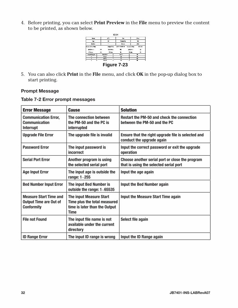
4. Before printing, you can select Print Preview in the File menu to preview the content to be printed, as shown below.
Figure 7-23
5. You can also click Print in the File menu, and click OK in the pop-up dialog box to start printing.
Prompt Message
Table 7-� error prompt messages
Error Message Cause Solution
Communication Error, Communication Interrupt
The connection between the PM-50 and the PC is interrupted
Restart the PM-50 and check the connection between the PM-50 and the PC
Upgrade File Error The upgrade file is invalid Ensure that the right upgrade file is selected and conduct the upgrade again
Password Error The input password is incorrect
Input the correct password or exit the upgrade operation
Serial Port Error Another program is using the selected serial port
Choose another serial port or close the program that is using the selected serial port
Age Input Error The input age is outside the range: 1∼255
Input the age again
Bed Number Input Error The input Bed Number is outside the range: 1∼65535
Input the Bed Number again
Measure Start Time and Output Time are Out of Conformity
The input Measure Start Time plus the total measured time is later than the Output Time
Input the Measure Start Time again
File not Found The input file name is not available under the current directory
Select file again
ID Range Error The input ID range is wrong Input the ID Range again

33JB7401-INS-LABRevA07
8 ACCeSSoRIeSGraham-Field recommends the following Sp02 sensors for use with the PM-50 Pulse Oxim-eter.
CAUTIoN: Using other accessories than those listed below may cause damage to the device.
Description Part Number
Pulse Oximeter Management System (Includes PMS Software CD and Communication Cable); Requires PC Running Windows 98/2000/XP
JB7401-01
Reusable 518A multi-functional SpO2 Sensor JB7401-02
Reusable 512D Finger SpO2 Sensor JB7401-03
Single-Patient Adult SpO2 sensor * JB7401-04
Single-Patient Child SpO2 sensor * JB7401-05
Single-Patient Infant SpO2 sensor * JB7401-06
* Note: Adult > 30 kg (66 lb.) Child = 10 - 50 kg (22 - 110 lb.) Infant = 3 - 20 kg (6.6 - 44 lb.)

34 JB7401-INS-LABRevA07
9 SPeCIFICATIoNSNote:Inadditiontothefollowingspecifications,adocumentcontainingadditionaltechnical
specifications,includingParameter SpecificationsandEMC Specifications,isalsoavailable;ifyourequirefurtherinformation,pleasecall800-347-5678andspeakwithGraham-FieldHealthProducts’QualityDepartmenttorequestsaiddocument.
geNeRAL SPeCIFICATIoNS
Basics
Product Model: PM-50
Product Name: Pulse Oximeter
Classification: IIb (According to MDD 93/42EEC directive) II (21CFR 870.2700, 870.2710)
Safety designations (per IeC 60601-1 Standard)
Type of protection against electric shock: Internally powered equipment.
Degree of protection against electric shock: Type BF
Mode of operation: Continuous
Protection Against Ingress of Liquids: Not protected (Ordinary) - IPX0 per IEC60529
dISPLAy ANd CoNTRoL
display
Display Type: Matrix LCD
Display Area: Not less than 42mm×35mm (1.65 x 1.38 in.)
Back Light: Blue
Display Information: SpO2, PR, Pulse strength, ID number, Memory Full, ID Full, Low battery, Standby, Communication, Technical error
Buttons
Power Button: Switches the oximeter on/off. The power-on is not delayed and the power-off has a 2 second delay
Backlight button: Switches the backlight on/off
ID Confirm button: Confirms whether to use the previous ID for the new measurement
Backlight button + ID Confirm button
Deletes data
Power Saving FeaturesRefer to section5 OTHER FUNCTIONS, Power Management.
ConnectorOne dual-purpose socket for connecting SpO2 sensor and communication cable.

35JB7401-INS-LABRevA07
eLeCTRICAL SPeCIFICATIoNS
Working Voltage: 4.0 to 6.4 VDC
Power Supply: Batteries
Battery Specifications: Four Common 1.5V AA alkaline or rechargeable batteries
Shutdown Leakage Current: < 200uA
Battery Run Time: 15-hour continuous operation with alkaline batteries
Power Consumption 720mW
PRINTINg
Printer: The PC’s printer
Paper: A4
Content: ID data and trend data
PhySICAL ChARACTeRISTICS
Maximum Size: W×H×D: 65 × 140 × 32mm (2.56 x 5.51 x 1.26 in.)
Maximum Weight: Not including battery and sensor: 130g (.29 lb.)
eNVIRoNMeNT ANd SAFeTy
Temperature
Operation: 0°C to 50°C (32°F to 122°F)
Transportation and storage: -20°C to 60°C (-4°F to 140°F)
humidity
Operation: 15% to 95% (noncondensing)
Transportation and storage: 10% to 95% (noncondensing)
Altitude
Operation: -500 to 4,600 m (-1,600 to 15,000 feet)
Transportation and storage: -500 to 13,100 m (-1,600 to 43,000 feet)
TransportationMeets the 1A requirements of the ISTA transportation test procedure.
ShockMeets all the specifications after being exposed a half sinusoidal pulse that is 15g and 11ms, as required by IEC 68-2-27.

36 JB7401-INS-LABRevA07
10 LIMITed WARRANTyGF Health Products, Inc. warrants the Mindray PM-50 Pulse Oximeter against manufac-turing defects in materials and workmanship as listed below:
PM-50 Pulse Oximeter: three (3) years PM-50 Accessories: six (6) months
If within the warranty period, the product or component part is proven to GF Health Products, Inc.'s satisfaction to be defective, GF Health Products, Inc. shall provide, at its option, one of the following: (1) repair or replacement of any defective or nonconform-ing part or product or (2) a credit and/or refund of the original selling price. GF HEALTH PRODUCTS, INC.'S SOLE OBLIGATION AND YOUR EXCLUSIVE REMEDY UNDER THIS WAR-RANTY SHALL BE LIMITED TO SUCH REPAIR, REPLACEMENT, CREDIT AND/OR REFUND.
LIMITATIONS AND EXCLUSIONS: The foregoing warranty shall not apply to serial num-bered products if the serial number has been removed or defaced. Products subjected to negligence, abuse, misuse, improper operation, improper maintenance, improper clean-ing, improper storage, or damages beyond GF Health Products, Inc.'s control are not cov-ered by this warranty, and that evaluation shall be solely determined by GF Health Prod-ucts, Inc. This warranty shall not apply to problems arising from normal wear and tear or failure to follow instructions. The warranty shall also not apply to products modified without GF Health Products, Inc.'s express written consent; nor shall it apply if parts not complying with original equipment specifications are added to GF Health Products, Inc. products, or if the product or part is serviced by an entity not authorized by GF Health Products, Inc.
THE FOREGOING WARRANTY IS EXCLUSIVE AND IN LIEU OF ALL OTHER EXPRESS WARRANTIES AND IMPLIED WARRANTIES, INCLUDING BUT NOT LIMITED TO THE IMPLIED WARRANTIES OF MERCHANTABILITY AND FIT-NESS FOR A PARTICULAR PURPOSE, AND SHALL NOT EXTEND BEYOND THE DURATION OF THE EXPRESS WARRANTY PROVIDED HEREIN, AND THE REMEDY FOR VIOLATIONS OF ANY IMPLIED WARRANTY SHALL BE LIMITED TO THE REPAIR, REPLACEMENT, CREDIT AND/OR REFUND OF THE DEFECTIVE PRODUCT OR PART PURSUANT TO THE TERMS CONTAINED HEREIN. GF HEALTH PRODUCTS, INC. SHALL NOT BE LIABLE FOR ANY CONSEQUENTIAL OR INCIDENTAL DAMAGES WHATSOEVER.
This warranty gives you specific legal rights and you may also have other legal rights which vary from state to state. Some states do not allow the exclusion or limitation of incidental or consequential damage, or limitation on how long an implied warranty lasts, so the above exclusion and limitations may not apply to you.

37JB7401-INS-LABRevA07
11 INdexAAccessories 33Appearance 9
BBacklight button 11Batteries, install 12Battery detection 20Button operation 11
CCAUTION statement, significance 5Cleaning 21Computer, connect 13Contraindications 8Conventions of this manual 4
dDANGER statement, significance 4Data adding 18Data area 27Data management 17Data output 27Data protection 18Data storage 17Disinfection 22Disposal 22
eEnergy saving 20Equipment symbols 7
FFile management 30Functions 8, 27
gGeneral 8
IIllustrations in this manual 4Inaccurate measurements, possible causes 16Inspection 12Intended audience of this manual 4Introduction 8
MMain interface 24Maintenance 21Measurement 14Measurement, adult or child 15Measuring principle 14Menu bar 24Messages prompting 19
NNames in this manual 4Note, significance 5
oOther functions 17
PPatient information, modify 31Power management 20Print data 31Prompt message 32Pulse oximeter management system 23
SSafety information 4Sensor measurement wavelengths 14Software, install 12, 23Software, uninstall 23Software upgrade 28Specifications, additional 34Specifications, basics 34Specifications, buttons 34Specifications, connector 34Specifications, control 34Specifications, electrical 35Specifications, environment and safety 35Specifications, general 34Specifications, physical characteristics 35Specifications, printing 35SpO2 monitoring 14SpO2 sensor, connect 13SpO2 sensor, placement, adult or child 15System check 21
TTrend data zone 17
UUnpacking 12
VVersion information for this manual 4
WWARNING statement, significance 4Warranty, limited 36

38 JB7401-INS-LABRevA07
NoTeS

39JB7401-INS-LABRevA07
NoTeS

USA, Corporate Headquarters:
Graham-Field Health Products 2935 Northeast Parkway Atlanta, Georgia 30360
telephone: 800-347-5678, 770-447-1609 fax: 800-726-0601, 678-291-3232
www.grahamfield.com
JB7401-INS-LABRevA07 © GF Health Products, Inc., July 2007
Mindray is a registered trademark of Shenzhen Mindray Bio-Medical Electronics Co., Ltd.
GF and Graham-Field are registered trademarks of GF Health Products, Inc.
GF Health Products, Inc. is not responsible for typographical errors. Packaging, warranties and products are subject to change without notice.