MILLING MACHINE OWNER'S MANUAL MODEL G3616… · G. Coolant Hose H. Longitudinal Feed Handwheel (2...
72
COPYRIGHT © JUNE, 2005 BY GRIZZLY INDUSTRIAL, INC. REVISED OCTOBER, 2007. (TR) WARNING: NO PORTION OF THIS MANUAL MAY BE REPRODUCED IN ANY SHAPE OR FORM WITHOUT THE WRITTEN APPROVAL OF GRIZZLY INDUSTRIAL, INC. #TR7337 PRINTED IN CHINA MODEL G3616/G3617 MILLING MACHINE OWNER'S MANUAL
Transcript of MILLING MACHINE OWNER'S MANUAL MODEL G3616… · G. Coolant Hose H. Longitudinal Feed Handwheel (2...

COPYRIGHT © JUNE, 2005 BY GRIZZLY INDUSTRIAL, INC. REVISED OCTOBER, 2007. (TR)WARNING: NO PORTION OF THIS MANUAL MAY BE REPRODUCED IN ANY SHAPE
OR FORM WITHOUT THE WRITTEN APPROVAL OF GRIZZLY INDUSTRIAL, INC. #TR7337 PRINTED IN CHINA
MODEL G3616/G3617MILLING MACHINE
OWNER'S MANUAL

�������������������������������������������������������������������������������������������������������������������������������������
������������������������������������������������������������������������������������������������������������������������������������������������������������������
�������������������������������������������������������������������������������������������������������������������������������������������������������������������������������������������������������������������������������������������������������������������������������������������������������������������������������������������������������������������������������������������������������
�������������������������������������������������������������������������������������������������������������������������������������������
������������������������������������������������������������������������������������������������������������������������������������������������������������������������������������������������������������������������������������������������������
�� ������������������������������ �������������������������������������������������������������������� ����������������������������������������������������
�������������������������������������������������������������������������������������������������������������������������������������������������������������������������������������������������������������������������������������������������������������������������������������������������������

G3616/G3617 Mill 1
Table of ContentsINTRODUCTION ............................................................................................................................... 3
Foreword .................................................................................................................................... 3Contact Info ................................................................................................................................ 3Identification ............................................................................................................................... 4G3616 Machine Data Sheet ....................................................................................................... 5G3617 Machine Data Sheet ....................................................................................................... 8
SECTION 1: SAFETY ..................................................................................................................... 11Safety Instructions for Machinery ............................................................................................. 11Additional Safety Instructions for Mills ..................................................................................... 13
SECTION 2: CIRCUIT REQUIREMENTS ...................................................................................... 14110/220V Single-Phase ........................................................................................................... 14Grounding ................................................................................................................................. 15Extension Cords ....................................................................................................................... 15Rewiring to 110V ...................................................................................................................... 15
SECTION 3: SET UP ...................................................................................................................... 16About This Section ................................................................................................................... 16Items Needed for Set Up ......................................................................................................... 16Unpacking ................................................................................................................................ 16Inventory ................................................................................................................................... 17Hardware Recognition Chart .................................................................................................... 18Clean Up .................................................................................................................................. 19Site Considerations .................................................................................................................. 19Mounting to Floor ..................................................................................................................... 19Way Cover Installation ............................................................................................................. 21Handle Installation .................................................................................................................... 21
SECTION 4: OPERATION .............................................................................................................. 22Operation Safety ...................................................................................................................... 22Setting RPM ............................................................................................................................. 22Turning Spindle ON .................................................................................................................. 24Loading Tools ........................................................................................................................... 25Unloading Tools ....................................................................................................................... 26Spindle Head Positioning ......................................................................................................... 26Table Rotation .......................................................................................................................... 28Vise Rotation ............................................................................................................................ 28Table Travel ............................................................................................................................. 29Quill Travel ............................................................................................................................... 30Power Feed .............................................................................................................................. 30Coolant System ........................................................................................................................ 31Spindle Break-In Procedure ..................................................................................................... 31
SECTION 5: ACCESSORIES ......................................................................................................... 32SECTION 6: MAINTENANCE ........................................................................................................ 35
General ..................................................................................................................................... 35Schedule .................................................................................................................................. 35Cleaning ................................................................................................................................... 35Unpainted Cast Iron ................................................................................................................. 35Lubrication ................................................................................................................................ 36Checking/Adding Coolant ......................................................................................................... 38Changing Coolant .................................................................................................................... 38
2 G3616/G3617 Mill
SECTION 7: SERVICE ................................................................................................................... 39About Service ........................................................................................................................... 39Troubleshooting ........................................................................................................................ 40Replacing V-belts ..................................................................................................................... 42Adjusting Gibs .......................................................................................................................... 44G3616 Wiring Box Identification ............................................................................................... 45G3616 110V Wiring Diagram ................................................................................................... 46G3616 220V Wiring Diagram ................................................................................................... 47G3617 Wiring Box Identification ............................................................................................... 48G3617 110V Wiring Diagram ................................................................................................... 49G3617 220V Wiring Diagram ................................................................................................... 50Column Parts Breakdown ........................................................................................................ 51Column Parts List ..................................................................................................................... 52Rotary Table Parts Breakdown ................................................................................................ 53Rotary Table Parts List ............................................................................................................ 54Head Parts Breakdown ............................................................................................................ 55Head Parts List ......................................................................................................................... 56G3617 Horizontal Spindle Parts Breakdown ............................................................................ 57G3617 Horizontal Spindle Parts List ........................................................................................ 58Power Feed Parts Breakdown ................................................................................................. 59Power Feed Parts List .............................................................................................................. 60Power Feed Parts List, continued ............................................................................................ 61G3616 Electrical Parts Breakdown .......................................................................................... 62G3616 Electrical Parts List ....................................................................................................... 63G3617 Electrical Parts Breakdown .......................................................................................... 64G3617 Electrical Parts List ....................................................................................................... 65
WARRANTY AND RETURNS ........................................................................................................ 66

G3616/G3617 Mill 3
Foreword
INTRODUCTION
Read the manual before assembly and operation. Serious personal injury may result if safety or operational information is not understood or fol-lowed.
NOTICEThis machine is designed for highly skilled individuals who have an understanding of metalworking. This manual instructs on the assembly and controls of this machine, but does not describe the skills and techniques involved in crafting metal. If you are not an experienced metalworker, additional infor-mation sources are necessary to realize the full potential of this machine. Classes, trade journals, metalworking magazines, and your local library are good places to start.
We are proud to offer the Model G3616/G3617 Mill. This machine is part of a growing Grizzly family of fine metalworking machinery. When used according to the guidelines set forth in this manual, you can expect years of trouble-free, enjoyable operation and proof of Grizzly’s com-mitment to customer satisfaction.
We are pleased to provide this manual with the Model G3616/G3617. It was written to guide you through assembly, review safety considerations, and cover general operating procedures.
The specifications, drawings, and photographs illustrated in this manual represent the Model G3616/G3617 as supplied when the manual was prepared. For your convenience, we always keep current Grizzly manuals available on our website at www.grizzly.com. Any updates to your machine will be reflected in these manuals as soon as they are complete.
If you have any comments regarding this manual, please write to us at the address below:
Grizzly Industrial, Inc.c/o Technical Documentation Manager
P.O. Box 2069Bellingham, WA 98227-2069
We stand behind our machines. If you have any service questions or parts requests, please call or write us at the location listed below.
Grizzly Industrial, Inc.1203 Lycoming Mall Circle
Muncy, PA 17756Phone: (570) 546-9663
Fax: (800) 438-5901E-Mail: [email protected] Site: http://www.grizzly.com
Contact Info

4 G3616/G3617 Mill
S
Figure 1. The following is a list of controls and components on the Model G3616/G3617. Please take time to become familiar with each term and its location. These terms will be used throughout the manual and knowing them is essential to understanding the instructions and terminology used in this manual.
Identification
A
A. Vertical Spindle ON/OFF SwitchB. Coolant ON/OFF SwitchC. Vertical Spindle Speed Setting ChartD. Vertical Quill Travel LockE. Vertical SpindleF. Work LightG. Coolant HoseH. Longitudinal Feed Handwheel (2 Places)I. Powerfeed Hard Stop (2 Places)J. Longitudinal Feed Lock (2 Places)K. Knee Feed HandwheelL. Cross Feed HandwheelM. Coolant TrayN. Powerfeed Limit Switch
O. Emergency StopP. Horizontal Spindle ON/OFFQ. Cross Feed Lock (2 Places)R. Knee Feed Lock (2 Places)S. Powerfeed ControlsT. Horizontal Spindle Speed Setting ChartU. Access Cover for Horizontal Spindle Speed
AdjustmentV. Horizontal Spindle (G3617 only)W. Quill Feed Handle and LockX. Micro-Feed Adjustment HandleY. Access Panel for Vertical Spindle Speed
Adjustment
BCD
E
F
G
H
I
J
K
L M
NO
P Q
R
S
H
I
T
UV
W
X
Y

G3616/G3617 Mill 5
The information contained herein is deemed accurate as of 10/1/2007 and represents our most recent product specifications.Due to our ongoing improvement efforts, this information may not accurately describe items previously purchased. PAGE 1 OF 3Model G3616
MACHINE DATASHEET
Customer Service #: (570) 546-9663 · To Order Call: (800) 523-4777 · Fax #: (800) 438-5901
MODEL G3616 VERTICAL MILLProduct Dimensions:
Weight............................................................................................................................................................ 1322 lbs.Length/Width/Height...................................................................................................41-15/16 x 41-3/4 x 80-15/16 in.Foot Print (Length/Width)....................................................................................................................... 28-3/4 x 18 in.
Shipping Dimensions:
Type........................................................................................................................................................... Wood CrateContent............................................................................................................................................................ MachineWeight............................................................................................................................................................ 1996 lbs.Length/Width/Height............................................................................................................................. 44 x 45 x 88 in.
Electrical:
Switch................................................................................................................................................ Forward/ReverseSwitch Voltage...................................................................................................................................................... 220VCord Length............................................................................................................................................................ 6 ft.Cord Gauge....................................................................................................................................................12 gaugeRecommended Breaker Size................................................................................15 amps at 220V, 30 amps at 110VPlug.......................................................................................................................................................................... No
Motors:
Main
Type.................................................................................................................. TEFC Capacitor Start InductionHorsepower.................................................................................................................................................2 HPVoltage.................................................................................................................................................110/220VPrewired......................................................................................................................................................220VPhase........................................................................................................................................................ SingleAmps........................................................................................................................................................20/10ASpeed.................................................................................................................................................1725 RPMCycle..........................................................................................................................................................60 HzNumber Of Speeds........................................................................................................................................... 1Power Transfer ............................................................................................................................... V-Belt DriveBearings........................................................................................................ Shielded, Permanently Lubricated
Coolant
Type................................................................................................................................................... AC SealedHorsepower..............................................................................................................................................1/8 HPVoltage.................................................................................................................................................110/220VPrewired......................................................................................................................................................220VPhase........................................................................................................................................................ SingleAmps....................................................................................................................................................0.9/0.45ACycle..........................................................................................................................................................60 HzNumber Of Speeds........................................................................................................................................... 1Power Transfer ................................................................................................................................Direct DriveBearings........................................................................................................ Shielded, Permanently Lubricated
G3616 Machine Data Sheet

6 G3616/G3617 Mill
The information contained herein is deemed accurate as of 10/1/2007 and represents our most recent product specifications.Due to our ongoing improvement efforts, this information may not accurately describe items previously purchased. PAGE 2 OF 3Model G3616
Main Specifications:
Operation Info
Spindle Travel.............................................................................................................................................. 5 in.Swing..........................................................................................................................................................44 in.Longitudinal Table Travel.....................................................................................................................15-1/2 in.Cross Table Travel.................................................................................................................................8-1/2 in.Vert. Table Travel.......................................................................................................................................13 in.Table Swivel.................................................................................................................... Left and Right 45 deg.Knee Travel................................................................................................................................................ 13 in.Ram Travel.................................................................................................................................................11 in.Ram Swivel Angle................................................................................................................................... 90 deg.Head Travel..................................................................................................................................................5 in.Head Swivel............................................................................................................................................ 90 deg.Head Tilt.......................................................................................................................... Left and Right 90 deg.Turret Or Column Swivel................................................................................................. Left and Right 90 deg.Max. Dist Spindle To Column.....................................................................................................................22 in.Max. Dist Spindle To Table........................................................................................................................ 15 in.Drilling Cap For Cast Iron.......................................................................................................................1-1/4 in.Drilling Cap For Steel............................................................................................................................. 1-1/4 in.No. Of Vert. Spindle Speeds............................................................................................................................. 9Range Of Vert. Spindle Speeds..................................... 270, 390, 490, 615, 860, 930, 1600, 1960, 2950 RPMNo. Of Longitudinal Feeds..................................................................................................................... VariableFeed Rate....................................................................................................................................... 0 - 140 RPMQuill Dia..................................................................................................................................................3-1/2 in.
Table Info
Table Length........................................................................................................................................ 31-1/2 in.Table Width............................................................................................................................................ 9-1/2 in.Table Thickness..................................................................................................................................... 2-1/2 in.No. Of T Slots....................................................................................................................................................3T Slots Width......................................................................................................................................... 0.640 in.T Slots Height...............................................................................................................................................1 in.T Slots Centers...................................................................................................................................... 1-5/8 in.Stud Size................................................................................................................................................... 1/2 in.
Lead Screw Info
Lead Screw Diameter...................................................................................................................................1 in.Lead Screw TPI.................................................................................................................................................5Lead Screw Length.................................................................................................................................... 37 in.
Construction
Spindle Housing Const......................................................................................................................... Cast IronTable Const................................................................................................................Surface Ground Cast IronHead Const...........................................................................................................................................Cast IronColumn Const.......................................................................................................................................Cast IronBase Const........................................................................................................................................... Cast IronPaint.......................................................................................................................................................... Epoxy
Other
Collars Calibrated..................................................................................................................................0.001 in.
Spindle Info
Spindle Taper................................................................................................................................................ R-8End Milling Cap............................................................................................................................................ 1 in.Face Milling Cap...........................................................................................................................................3 in.Draw Bar Diameter................................................................................................................................0.550 in.Draw Bar TPI...................................................................................................................................................20Draw Bar Length.................................................................................................................................. 16-5/8 in.Spindle Bearings..........................................................................................................................Roller and Ball
550 1800

G3616/G3617 Mill 7
The information contained herein is deemed accurate as of 10/1/2007 and represents our most recent product specifications.Due to our ongoing improvement efforts, this information may not accurately describe items previously purchased. PAGE 3 OF 3Model G3616
Other Specifications:
Country Of Origin ................................................................................................................................................ChinaWarranty ............................................................................................................................................................ 1 YearSerial Number Location ........................................................................................................... Label on Head CastingAssembly Time .......................................................................................................................................... 1-1/2 hours
Features:
Coolant SystemFine Down FeedReversing SwitchLongitudinal Power FeedWork LightCentralized Controls
Accessories Included:
Drill Chuck with ArborMilling ViseSet of R-8 Collets

8 G3616/G3617 Mill
The information contained herein is deemed accurate as of 10/1/2007 and represents our most recent product specifications.Due to our ongoing improvement efforts, this information may not accurately describe items previously purchased. PAGE 1 OF 3Model G3617
MACHINE DATASHEET
Customer Service #: (570) 546-9663 · To Order Call: (800) 523-4777 · Fax #: (800) 438-5901
MODEL G3617 HORIZONTAL / VERTICAL MILLProduct Dimensions:
Weight............................................................................................................................................................ 2054 lbs.Length/Width/Height.................................................................................................................54-7/8 x 59 x 80-3/4 in.Foot Print (Length/Width)................................................................................................................. 35-5/8 x 20-1/2 in.
Shipping Dimensions:
Type........................................................................................................................................................... Wood CrateContent............................................................................................................................................................ MachineWeight............................................................................................................................................................ 2429 lbs.Length/Width/Height............................................................................................................................. 53 x 45 x 88 in.
Electrical:
Switch................................................................................................................................................ Forward/ReverseSwitch Voltage...................................................................................................................................................... 220VCord Length............................................................................................................................................................ 6 ft.Cord Gauge....................................................................................................................................................12 gaugeRecommended Breaker Size................................................................................15 amps at 220V, 30 amps at 110VPlug.......................................................................................................................................................................... No
Motors:
Vertical
Type.......................................................................................................................... TEFC Capacitor Start/RunHorsepower.................................................................................................................................................2 HPVoltage.................................................................................................................................................110/220VPrewired......................................................................................................................................................220VPhase........................................................................................................................................................ SingleAmps........................................................................................................................................................20/10ASpeed.................................................................................................................................................1725 RPMCycle..........................................................................................................................................................60 HzNumber Of Speeds........................................................................................................................................... 1Power Transfer .........................................................................................................................................V-BeltBearings........................................................................................................ Shielded, Permanently Lubricated
Horizontal
Type.......................................................................................................................... TEFC Capacitor Start/RunHorsepower...........................................................................................................................................1-1/2 HPVoltage.................................................................................................................................................110/220VPrewired......................................................................................................................................................220VPhase........................................................................................................................................................ SingleAmps..........................................................................................................................................................16/8ASpeed.................................................................................................................................................1725 RPMCycle..........................................................................................................................................................60 HzNumber Of Speeds........................................................................................................................................... 1Power Transfer .........................................................................................................................................V-BeltBearings........................................................................................................ Shielded, Permanently Lubricated
G3617 Machine Data Sheet

G3616/G3617 Mill 9
The information contained herein is deemed accurate as of 10/1/2007 and represents our most recent product specifications.Due to our ongoing improvement efforts, this information may not accurately describe items previously purchased. PAGE 2 OF 3Model G3617
Coolant
Type................................................................................................................................................... AC SealedHorsepower..............................................................................................................................................1/8 HPVoltage.................................................................................................................................................110/220VPrewired......................................................................................................................................................220VPhase........................................................................................................................................................ SingleAmps....................................................................................................................................................0.9/0.45ACycle..........................................................................................................................................................60 HzNumber Of Speeds........................................................................................................................................... 1Power Transfer ................................................................................................................................Direct DriveBearings........................................................................................................ Shielded, Permanently Lubricated
Main Specifications:
Operation Info
Spindle Travel.............................................................................................................................................. 5 in.Swing..........................................................................................................................................................54 in.Longitudinal Table Travel........................................................................................................................... 22 in.Cross Table Travel.................................................................................................................................8-1/2 in.Vert. Table Travel.......................................................................................................................................13 in.Table Swivel.................................................................................................................... Left and Right 45 deg.Knee Travel................................................................................................................................................ 13 in.Ram Travel.................................................................................................................................................11 in.Ram Swivel Angle................................................................................................................................... 90 deg.Head Travel..................................................................................................................................................5 in.Head Swivel............................................................................................................................................ 90 deg.Head Tilt.......................................................................................................................... Left and Right 90 deg.Turret Or Column Swivel................................................................................................. Left and Right 90 deg.Max. Dist Spindle To Column.....................................................................................................................27 in.Max. Dist Spindle To Table.................................................................................................................. 13-3/4 in.Drilling Cap For Cast Iron.......................................................................................................................1-1/4 in.Drilling Cap For Steel............................................................................................................................. 1-1/4 in.Max. Dist Horz. Spindle Center To Table.............................................................................................11-3/8 in.No. Of Vert. Spindle Speeds............................................................................................................................. 9Range Of Vert. Spindle Speeds..................................... 270, 390, 490, 615, 860, 930, 1600, 1960, 2950 RPMNo. Of Horz. Spindle Speeds............................................................................................................................ 8Range Of Horz. Spindle Speeds.................................................. 72, 170, 210, 240, 290, 550, 830, 1300 RPMNo. Of Longitudinal Feeds..................................................................................................................... VariableFeed Rate....................................................................................................................................... 0 - 140 RPMQuill Dia..................................................................................................................................................3-1/2 in.
Table Info
Table Length........................................................................................................................................ 39-3/8 in.Table Width............................................................................................................................................ 9-1/2 in.Table Thickness..................................................................................................................................... 2-1/2 in.No. Of T Slots....................................................................................................................................................3T Slots Width......................................................................................................................................... 0.640 in.T Slots Height...............................................................................................................................................1 in.T Slots Centers.............................................................................................................................................3 in.Stud Size................................................................................................................................................... 1/2 in.
Lead Screw Info
Lead Screw Diameter...................................................................................................................................1 in.Lead Screw TPI.................................................................................................................................................5Lead Screw Length.................................................................................................................................... 43 in.
10 G3616/G3617 Mill
The information contained herein is deemed accurate as of 10/1/2007 and represents our most recent product specifications.Due to our ongoing improvement efforts, this information may not accurately describe items previously purchased. PAGE 3 OF 3Model G3617
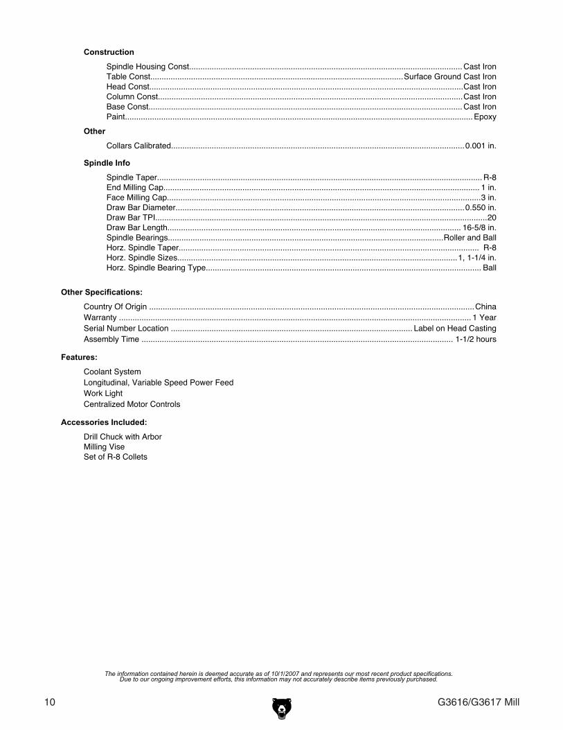
Construction
Spindle Housing Const......................................................................................................................... Cast IronTable Const................................................................................................................Surface Ground Cast IronHead Const...........................................................................................................................................Cast IronColumn Const.......................................................................................................................................Cast IronBase Const........................................................................................................................................... Cast IronPaint.......................................................................................................................................................... Epoxy
Other
Collars Calibrated..................................................................................................................................0.001 in.
Spindle Info
Spindle Taper................................................................................................................................................ R-8End Milling Cap............................................................................................................................................ 1 in.Face Milling Cap...........................................................................................................................................3 in.Draw Bar Diameter................................................................................................................................0.550 in.Draw Bar TPI...................................................................................................................................................20Draw Bar Length.................................................................................................................................. 16-5/8 in.Spindle Bearings..........................................................................................................................Roller and BallHorz. Spindle Taper..................................................................................................................................... R-8Horz. Spindle Sizes............................................................................................................................1, 1-1/4 in.Horz. Spindle Bearing Type.......................................................................................................................... Ball
Other Specifications:
Country Of Origin ................................................................................................................................................ChinaWarranty ............................................................................................................................................................ 1 YearSerial Number Location ........................................................................................................... Label on Head CastingAssembly Time .......................................................................................................................................... 1-1/2 hours
Features:
Coolant SystemLongitudinal, Variable Speed Power FeedWork LightCentralized Motor Controls
Accessories Included:
Drill Chuck with ArborMilling ViseSet of R-8 Collets

G3616/G3617 Mill 11
SECTION 1: SAFETY
For Your Own Safety Read Instruction Manual Before Operating This Equipment
Indicates an imminently hazardous situation which, if not avoided, WILL result in death or serious injury.
Indicates a potentially hazardous situation which, if not avoided, COULD result in death or serious injury.
Indicates a potentially hazardous situation which, if not avoided, MAY result in minor or moderate injury. It may also be used to alert against unsafe practices.
This symbol is used to alert the user to useful information about proper operation of the equipment.
The purpose of safety symbols is to attract your attention to possible hazardous conditions. This manual uses a series of symbols and signal words which are intended to convey the level of importance of the safety messages. The progression of symbols is described below. Remember that safety messages by themselves do not eliminate danger and are not a substitute for proper accident prevention measures.
NOTICE
4. ALWAYS WEAR AN ANSI APPROVED RESPIRATOR WHEN OPERATING MACHINERY THAT PRODUCES DUST. Wood dust is a carcinogen and can cause cancer and severe respiratory illnesses.
5. ALWAYS USE HEARING PROTECTION WHEN OPERATING MACHINERY. Machinery noise can cause permanent hearing damage.
6. WEAR PROPER APPAREL. DO NOT wear loose clothing, gloves, neckties, rings, or jewelry which may get caught in moving parts. Wear protective hair covering to con-tain long hair and wear non-slip footwear.
1. READ THROUGH THE ENTIRE MANUAL BEFORE STARTING MACHINERY. Machinery presents serious injury hazards to untrained users.
2. MAKE SURE ALL GUARDS ARE IN THEIR CORRECT PLACE AND WORK CORRECTLY BEFORE USING MACHINERY. NEVER OPERATE MACHINE WITHOUT GUARDS.
3. ALWAYS USE ANSI APPROVED SAFETY GLASSES WHEN OPERATING MACHINERY. Everyday eyeglasses only have impact resistant lenses, they are NOT safety glasses.
Safety Instructions for Machinery

12 G3616/G3617 Mill
7. NEVER OPERATE MACHINERY WHEN TIRED, OR UNDER THE INFLUENCE OF DRUGS OR ALCOHOL. Be mentally alert at all times when running machinery.
8. BEWARE WOOD DUST ALLERGIES. Certain woods may cause an allergic reac-tion in people and animals, especially when exposed to fine dust. Make sure you know what type of wood dust you will be exposed to and always wear and ANSI approved respirator.
9. ONLY ALLOW TRAINED AND PROP-ERLY SUPERVISED PERSONNEL TO OPERATE MACHINERY. Make sure oper-ation instructions are safe and clearly understood.
10. KEEP CHILDREN AND VISITORS AWAY. Keep all children and visitors a safe dis-tance from the work area.
11. MAKE WORKSHOP CHILD PROOF. Use padlocks, master switches, and remove start switch keys.
12. NEVER LEAVE WHEN MACHINE IS RUNNING. Turn power OFF and allow all moving parts to come to a complete stop before leaving machine unattended.
13. DO NOT USE IN DANGEROUS ENVIRONMENTS. DO NOT use machin-ery in damp, wet locations, or where any flammable or noxious fumes may exist.
14. KEEP WORK AREA CLEAN AND WELL LIT. Clutter and dark shadows may cause accidents.
15. USE A GROUNDED EXTENSION CORD RATED FOR THE MACHINE AMPERAGE. Undersized cords overheat and reduce voltage. Replace extension cords if they become damaged. DO NOT use extension cords for 220V machinery.
Safety Instructions for Machinery16. ALWAYS DISCONNECT FROM POWER
SOURCE BEFORE SERVICING MACHINERY. Make sure switch is in OFF position before reconnecting.
17. MAINTAIN MACHINERY WITH CARE. Keep blades sharp and clean for best and safest performance. Follow instructions for lubricating and changing accessories.
18. REMOVE ADJUSTING KEYS AND WRENCHES. Make a habit of checking for keys and adjusting wrenches before turn-ing ON machinery.
19. CHECK FOR DAMAGED PARTS BEFORE USING MACHINERY. Check for binding and alignment of parts, broken parts, part mounting, loose bolts, and any other conditions that may affect machine operation. Repair or replace damaged parts.
20. USE RECOMMENDED ACCESSORIES. Refer to the instruction manual for recom-mended accessories. The use of improper accessories may cause risk of injury.
21. DO NOT FORCE MACHINERY. Work at the speed for which the machine or acces-sory was designed.
22. SECURE WORKPIECE. Use clamps or a vise to hold the workpiece when practi-cal. A secured workpiece protects your hands and frees both hands to operate the machine.
23. DO NOT OVERREACH. Keep proper foot-ing and balance at all times.
24. MANY MACHINES WILL EJECT THE WORKPIECE TOWARD THE OPERATOR. Know and avoid conditions that cause the workpiece to be ejected.
25. ALWAYS LOCK MOBILE BASES BEFORE OPERATING MACHINERY.

G3616/G3617 Mill 13
Additional Safety Instructions for Mills
Like all power tools, there is danger asso-ciated with the Model G3616/G3617 Mill. Accidents are frequently caused by lack of familiarity or failure to pay attention. Use this tool with respect and caution to lessen the possibility of operator injury. If normal safety precautions are overlooked or ignored, serious personal injury may occur.
No list of safety guidelines can be complete. Every shop environment is different. Always consider safety first, as it applies to your individual working conditions. Use this and other machinery with caution and respect. Failure to do so could result in serious per-sonal injury, damage to equipment or poor work results.
10. UNSECURE BITS/CUTTERS. Be sure drill bit is securely locked in the chuck or cut-ter has been secured in a holder or collet before turning the mill ON.
11. DAMAGED MACHINE. Never operate mill if any part is damaged or broken until it is properly repaired or replaced.
12. PROPER CLEARANCE. Be sure cutter, workpiece and machine parts have proper working clearance throughout the range of motion you intend to use.
13. FINGER PROXIMITY. Never place your fin-gers in a position where drill or cutter could contact them if a part shifts unexpectedly. Serious personal injury could result.
14. ADJUSTMENTS DURING OPERATION. Never perform layout, assembly, or setup work on the mill while a bit or cutter is rotat-ing.
15. LEAVING MACHINE. Shut off power, remove drill or cutting tool, and clean tool before leaving machine.
16. EXPERIENCING DIFFICULTIES. If at any time you are experiencing difficulties per-forming the intended operation, stop using the machine! Then contact our Technical Support or ask a qualified expert how the operation should be performed.
1. SETUP. Do not use until mill is completely setup according to this instruction manual.
2. OPERATOR UNDERSTANDING. Do not use the mill until all controls and adjust-ments are understood.
3. ADJUSTMENT TOOLS. Ensure that all wrenches and adjusting keys have been removed before starting machine.
4. CORRECT SPEEDS. Always use the rec-ommended speeds and feeds with milling cutters and router bits.
5. DEPTH STOP. Adjust depth stop to prevent drilling into table work surface.
6. CLEAN WORK AREA. Keep area around the mill free from oil, tools, and chips.
7. HOLDING WORKPIECES. Never hold workpieces with your hands during milling or drilling. Instead, clamp it to the table or use a vise bolted to the table to secure workpiece and prevent rotation.
8. HANDLING SHARP CUTTERS. Never handle sharp cutters with bare hands. Paper towels or shop rags wrapped around them will help to avoid injury.
9. CLEANING OFF SHAVINGS. Always use a brush—not a rag—to remove metal shav-ings or chips.

14 G3616/G3617 Mill
SECTION 2: CIRCUIT REQUIREMENTS
Serious personal injury could occur if you connect the machine to the power source before you have completed the set up pro-cess. DO NOT connect the machine to the power source until instructed to do so.
110/220V Single-Phase
The Model G3616/G3617 Horizontal/Vertical Mill has two 110/220V single-phase motors. Both motors come prewired for 220V operation, which is the preferred power supply for the Model G3616/G3617. Only one motor will ever operate at a time, so the circuit requirements below are for the vertical spindle motor, which has the highest amp draw.
Amperage DrawThe 2 HP vertical spindle motor on the Model G3616/G3617 is the largest motor on the machine and it will draw the following amps, when com-bined with the coolant pump motor:
220V Connection ................................10.9 Amps110V Connection ..............................20.45 Amps
Circuit Breaker RequirementsInstall your machine on a dedicated circuit to reduce the possibility of tripping the circuit break-er. If the circuit breaker frequently trips, have the circuit inspected by a qualified electrician. Never use a larger circuit breaker than stated below, or you will increase the risk of fire.
220V Circuit Breaker .............................15 Amps110V Circuit Breaker .............................25 Amps
Figure 2. 6-15 plug and receptacle.
Figure 3. 5-30 plug and receptacle.
Plug TypeThe cord set enclosed does not have a plug as the style of plug you require will depend upon the type of service you currently have or plan to install. We recommend using the following plug and recep-tacles (see Figures 2 & 3 for examples):
220V Plug & Receptacle .............................. 6-15110V Plug & Receptacle .............................. 5-30
G3616/G3617 Mill 15
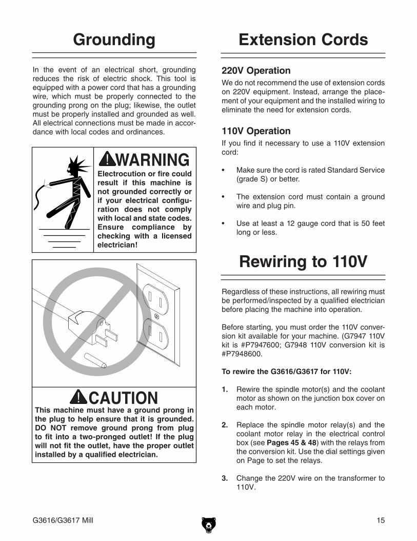
In the event of an electrical short, grounding reduces the risk of electric shock. This tool is equipped with a power cord that has a grounding wire, which must be properly connected to the grounding prong on the plug; likewise, the outlet must be properly installed and grounded as well. All electrical connections must be made in accor-dance with local codes and ordinances.
Grounding
This machine must have a ground prong in the plug to help ensure that it is grounded. DO NOT remove ground prong from plug to fit into a two-pronged outlet! If the plug will not fit the outlet, have the proper outlet installed by a qualified electrician.
Electrocution or fire could result if this machine is not grounded correctly or if your electrical configu-ration does not comply with local and state codes. Ensure compliance by checking with a licensed electrician!
220V OperationWe do not recommend the use of extension cords on 220V equipment. Instead, arrange the place-ment of your equipment and the installed wiring to eliminate the need for extension cords.
110V OperationIf you find it necessary to use a 110V extension cord:
• Make sure the cord is rated Standard Service (grade S) or better.
• The extension cord must contain a ground wire and plug pin.
• Use at least a 12 gauge cord that is 50 feet long or less.
Extension Cords
Regardless of these instructions, all rewiring must be performed/inspected by a qualified electrician before placing the machine into operation.
Before starting, you must order the 110V conver-sion kit available for your machine. (G7947 110V kit is #P7947600; G7948 110V conversion kit is #P7948600.
To rewire the G3616/G3617 for 110V:
1. Rewire the spindle motor(s) and the coolant motor as shown on the junction box cover on each motor.
2. Replace the spindle motor relay(s) and the coolant motor relay in the electrical control box (see Pages 45 & 48) with the relays from the conversion kit. Use the dial settings given on Page to set the relays.
3. Change the 220V wire on the transformer to 110V.
Rewiring to 110V

16 G3616/G3617 Mill
The Model G3616/G3617 is a heavy machine. Serious personal injury may occur if safe mov-ing methods are not fol-lowed. To be safe, you will need assistance and power equipment when moving the shipping crate and removing the machine from the crate.
The Model G3616/G3617 was carefully packed when it left our warehouse. If you discover the machine is damaged after you have signed for delivery, please immediately call Customer Service at (570) 546-9663 for advice.
Save the containers and all packing materials for possible inspection by the carrier or its agent. Otherwise, filing a freight claim can be difficult.
When you are completely satisfied with the con-dition of your shipment, you should inventory the contents.
The purpose of this section is to guide you through the required steps to get your machine out of its crate and into operating condition.
Wear safety glasses dur-ing the entire set up pro-cess!
This machine presents serious injury hazards to untrained users. Read through this entire manu-al to become familiar with the controls and opera-tions before starting the machine!
Unpacking
About This Section
SECTION 3: SET UP
The following items are needed to complete the set up process, but are not included with your machine:
Description Qty• Flat Head Screwdriver ................................ 1• Phillips Screwdriver, short handle .............. 1• Safety Glasses (for each person) .............. 1• 19mm Open-ended Wrench ....................... 1• Solvent (for cleaning) ......................... Varies• Shop rags (for cleaning) ..................... Varies
Items Needed for Set Up

G3616/G3617 Mill 17
Inventory
After the crate has been removed, you will find one wooden box, one tool box, one way cover, and one wrench, all attached to the base of the crate. A vise, with swivel base, is attached to the table of the mill. After all the parts have been removed from the two boxes, you should have the following items:
Figure 4. Wooden box and on-crate items.
Figure 5. Toolbox items.
In the event that any nonproprietary parts are missing (e.g. a nut or a washer), we would be glad to replace them, or for the sake of expedi-ency, replacements can be obtained at your local hardware store.
Tool Box (Figure 5 & 6) QtyA. Tool Box ..................................................... 1B. Drill Chuck, w/Key 1-16mm JT33 ............... 1C. Handwheel Handles ................................... 3D. Drift Key ...................................................... 1E. Hex Wrench ................................................ 1F. Wrench 21/24mm ...................................... 1G. R8 - MT2 Adaptor ....................................... 1H. R8 - MT3 Adaptor ....................................... 1I. R8 - JT33 Adaptor ...................................... 1J. One set R8 collets .................................... 13 includes: .................... 1⁄8, 3⁄16, 1⁄4, 5⁄16, 3⁄8, 7⁄16, .............................1⁄2, 9⁄16, 5⁄8, 11⁄16, 3⁄4, 13⁄16, 7⁄8K. Knee Handle ............................................... 1
Wooden Box/On-Crate Items (Figure 4) QtyA. Horizontal Arbor 11⁄4" (G3617 only) ............ 1B. Horizontal Arbor 1" (G3617 only) ............... 1C. Way Cover .................................................. 1D. Vertical Drawbar ......................................... 1E. Horizontal Drawbar (G3617 Only) .............. 1F. Wrench ....................................................... 1
Figure 6. Knee handle shown on mill.
A
B
C
D
E
A
J
H
I
G
B C
D
E
F
K
F

18 G3616/G3617 Mill
Hardware Recognition Chart

G3616/G3617 Mill 19
Although not required, we recommend that you mount your new milling machine to the floor. Because this is an optional step and floor mate-rials may vary, floor mounting hardware is not included.
Note: The instructions below are given for a typi-cal heavy-duty shop floor made of 6" thick con-crete. Also, anchor studs may be substituted for lag bolts, but they will stick out of the floor if you decide to move your machine at a later point.
Items Required: Qty• Hammer Drill .............................................. 1• 1⁄2" Punch (at least 8" Long) ....................... 1• 1⁄2" Hammer Drill Bit (at least 12" long) ...... 1• Lag Shields 5⁄16" x 3" (see Figure 8) .......... 4• Lag Bolts 5⁄16" x 8" ....................................... 4• Fender Washers 5⁄16" .................................. 4• Hammer ...................................................... 1• Precision Level ........................................... 1
Mounting to Floor
Figure 7. Working clearances.
Floor LoadThe weight and footprint size for your machine is located in the machine data sheet. Most commer-cial floors are suitable for your machine. Some residential floors may require additional reinforce-ment to support both the machine and operator.
Working ClearancesConsider existing and anticipated needs, size of material to be processed through each machine, and space for auxiliary stands, work tables or other machinery when establishing a location for your mill. See Figure 7 for the minimum working clearances of the Model G3616/G3617.
Unsupervised children and visitors inside your shop could cause serious per-sonal injury to themselves. Lock all entrances to the shop when you are away and DO NOT allow unsupervised children or visitors in your shop at any time!
The unpainted surfaces are coated with a waxy oil to protect them from corrosion during ship-ment. Remove this protective coating with a sol-vent cleaner or citrus-based degreaser such as Grizzly’s G7895 Degreaser. To clean thoroughly, some parts may need to be removed. For opti-mum performance from your machine, make sure you clean all moving parts or sliding contact surfaces that are coated. Avoid chlo-rine-based solvents as they may damage painted surfaces should they come in contact. Always follow the manufacturer’s instructions when using any type of cleaning product.
Site Considerations
Clean UpWall
Minimum 3 feet clearance
Maximum Table Travel (Left): 30 in.
Maximum Table Travel (Right): 36 in.
Figure 8. Typical lag bolt and shield anchor.

20 G3616/G3617 Mill
31⁄8" 31⁄8"
331⁄4" 85⁄8"
57⁄8"
183⁄8" 30"
52"
71⁄2"
81⁄2" 93⁄4"195⁄8"
153⁄4"
Figure 10. Foundation plan for machine installation (all units listed in mm).
Figure 9. Typical anchor stud.
Note: Anchor studs, as shown in Figure 9 below, are stronger and more permanent alternatives to lag shield anchors; however, they will stick out of the floor, which may cause difficulties if you decide to move your mill at a later point.
To mount the mill to the floor:
1. Locate the mill as close to electrical power as possible, providing a minimum of three feet of clearance between the back of machine and the wall.
2. Put on safety glasses and a dust mask before starting!
3. Use the mounting holes in the milling machine base to act as a guide, or layout holes as shown in Figure 10, for drilling into your floor, and drill approximately 31⁄2" deep into the concrete floor.
4. Using compressed air and a vacuum hose, remove the concrete dust from the newly drilled holes.
5. Using the hammer and punch, pound the lag shields into the concrete below the stand feet and flush with the surface of the concrete.
6. Secure the mill to the floor with the 5⁄16" lag bolts and washers. Use the level to make sure the table is flat along its travel. If it is not level, insert steel shims under the mill. Once the mill is level, finish tightening the bolts.

G3616/G3617 Mill 21
The way cover should be installed to protect and keep the back portion of the cross ways clean.
Tools required: QtyPhillips Screwdriver, short handle ..................... 1
To install the way cover:
1. Remove the four screws from the machine at the way cover mounting location (Figure 11). Note: The two screws located near the column use a nut and washer.
2. Place the way cover on the machine and align it with the fastener holes.
3. Attach the way cover with the four screws removed in Step 1.
Figure 11. Way cover mounted in the correct location on the machine.
Tools required: QtyFlat Head Screwdriver ....................................... 1
Install and tighten the three handles on the handwheels shown in Figure 12.
Figure 12. Locations for handle installation.
Way Cover Installation
Handle Installation
Screws (two each side)
Handle Installation Locations

22 G3616/G3617 Mill
SECTION 4: OPERATION
Damage to your eyes, lungs, and ears could result from using this machine without proper protective gear. Always wear safety glasses, a respirator, and hearing protection when operating this machine.
Loose hair and cloth-ing could get caught in machinery and cause serious personal injury. Keep loose clothing and long hair away from mov-ing machinery. Remove watches, rings, bracelets, and other jewelry from hands, wrists, and neck before operating the mill.
Operation Safety
NOTICEIf you have never used this type of machine or equipment before, WE STRONGLY REC-OMMEND that you read books, trade maga-zines, or get formal training before begin-ning any projects. Regardless of the con-tent in this section, Grizzly Industrial will not be held liable for accidents caused by lack of training.
Setting RPM
Whether using the vertical or horizontal spindle, you need to 1) determine the RPM needed to cut your workpiece, and 2) adjust the V-belts in the access panel for the spindle you will use for the operation.
To determine the needed RPM:
1. Use the table in Figure 13 to determine the cutting speed required for the material of your workpiece.
Cutting Speeds for High Speed Steel (HSS) Cutting Tools
Workpiece Material Cutting Speed (sfm)Aluminum & alloys 300
Brass & Bronze 150
Copper 100
Cast Iron, soft 80
Cast Iron, hard 50
Mild Steel 90
Cast Steel 80
Alloy Steel, hard 40
Tool Steel 50
Stainless Steel 60
Titanium 50
Plastics 300-800
Wood 300-500
Note: For carbide cutting tools, double the cutting speed. These values are a guideline only. Refer to the MACHINERY'S HANDBOOK for more detailed information.
Figure 13. Cutting speed table for HSS cutting tools.
2. Measure the diameter of your cutting tool in inches.
3. Use the following formula to determine the needed RPM for your operation:
(Cutting Speed x 4) / Tool Diameter = RPM

G3616/G3617 Mill 23
1 AG 72
2 BG 170
3 CG 210
4 AF 240
5 AE 290
6 BF 550
7 CE 830
8 BD 1300
DE 270 DG 930
CE 390 AF 1800
DF 550 BG 1960
BE 615 AG 2950
CF 860
A
CB
D
EF
G
VERTICAL SPINDLE SPEED CHARTSPINDLE MOTOR
Figure 14. Vertical spindle speed chart.
Always disconnect power to the machine before performing RPM adjust-ments. Failure to do this may result in serious per-sonal injury.
Figure 15. Vertical spindle access panel.
To adjust the V-belts for the vertical spindle:
1. Examine the Vertical Spindle Speed Chart (Figure 14 or on the front of the mill above the vertical spindle) to find the closest match to your needed RPM.
7. Move the rear V-belt to the appropriate pulley set for the given RPM.
8. Push the motor back into place and tighten the nut.
9. Replace the access cover by inserting the hand screws, then connect the machine to the power source.
To adjust the V-belts for the horizontal spin-dle:
1. Examine the Horizontal Spindle Speed Chart (Figure 16 or on the access cover at the rear of the mill) to find the closest match to your needed RPM.
2. Make sure the main power is disconnected from the machine before proceeding any fur-ther, as you will be working with the spindle V-belts and this is a dangerous area.
HORIZONTAL SPINDLE SPEED CHART
A
BC
GF
ED
UPPER
MIDDLE
MOTOR
Figure 16. Horizontal spindle speed chart.
60 HZ
R.P.M
1. Loosen these nuts.
2. Pull handle towards front of
machine.
2. Make sure the main power is OFF to the machine before proceeding any further, as you will be working with the spindle V-belts and this is a dangerous area.
3. Remove the access panel to the vertical spindle pulleys.
4. Loosen the motor nut next to the handle, loosen the center pulley nut (see Figure 15), and pull the motor forward to release tension on the V-belts.
5. Move the front belt to the desired position. You will need to move the center pulley set in order to accomplish this.
6. Move the center pulley set back to position and tighten the nut.

24 G3616/G3617 Mill
Figure 18. Vertical spindle ON/OFF switch.
Figure 19. Horizontal spindle ON/OFF switch.
Vertical Spindle1. Make sure the main power is ON.
2. Make sure hands and other items are clear of the cutting tool.
3. Using the ON/OFF switch shown in Figure 18, turn the spindle ON to the appropriate setting, based on the cutting tool setup.
Turning Spindle ON
Figure 17. Horizontal spindle access area.
Nut to Loosen/Tighten Tension
on V-Belts
5. Loosen the bolt that holds the center pul-ley set in place. The bolt can be accessed through opening next to the tension nut.
6. Remove the tension nut between the motor and the middle pulley sets to release tension on the V-belts.
7. Slide the center pulley set to the right to release the tension and allow belt move-ment.
8. Move the V-belts to the appropriate pulley sets for the needed RPM.
9. Move the center pulley set back into position, reinstall the tension nut, and bring the pulleys to the proper tension.
10. Tighten the nut to secure the center pulley set.
11. Close the access cover by inserting the hand screw, then connect the machine to the power source.
4. Open the access panel to the horizontal spindle pulleys (see Figure 17).
Horizontal Spindle (G3617 Only)1. Make sure main power is ON.
2. Make sure hands and other items are clear of the cutting tool.
3. Using the ON/OFF switch shown in Figure 19, turn the spindle ON in the appropriate direction, based on the cutting tool setup.
Vertical Spindle ON/OFF Switch
Horizontal Spindle ON/OFF Switch
Center Pulley Set

G3616/G3617 Mill 25
To load a tool in the vertical spindle:
1. Make sure the spindle is OFF.
2. Clean any debris from the spindle opening.
3. Insert the tool holder or a collet into the spin-dle.
4. Rotate the tool holder until the groove lines up with the key and the tool holder slides into the spindle.
5. Using a wrench, tighten the drawbar (see Figure 20) until the tool is secure in the spindle.
Figure 20. Vertical spindle with tool loaded.
Figure 21. Horizontal spindle with arbor loaded.
Loading Tools
6. Clear all items away from the cutting tool before turning the spindle ON.
To load a tool in the horizontal spindle (G3617 only):
1. Make sure the spindle is turned OFF.
2. Clean any debris from the spindle opening.
3. Rotate the vertical spindle 90º.
4. Rotate the spindle box 180º so that the spindle support is in-line with the horizontal spindle axis.
6. Rotate the arbor until the groove lines up with the key and the tool holder slides into the spindle.
7. Using a wrench, tighten the drawbar until the tool is secure in the spindle.
8. Adjust the spindle support distance to provide proper support during the cutting operation.
9. Tighten the arbor nut to keep the cutting tool and arbor secure.
10. Clear all items away from the cutting tool before turning the spindle ON.
Note: Remove the drawbar from the horizon-tal spindle when not in use.
5. Insert the arbor, with the cutting tool already loaded into the spindle (see Figure 21).
Drawbar at Top of Spindle
Drawbar at Back of Mill
Arbor Nut

26 G3616/G3617 Mill
The vertical spindle head can be positioned lin-early (parallel to the cross feed), vertically, and horizontally.
To position the spindle head linearly:
1. Make sure the spindle is stopped and the work area is free from obstructions before proceeding.
2. Loosen the two linear lock handles that lock the travel (see Figure 22).
Figure 22. Location for linear movement of head.
Linear Locks
Drive Nut
Spindle Head Positioning
To unload a tool from either spindle:
1. Make sure the spindle is turned OFF.
2. Remove any debris or chips from the tool and the tool holder/arbor.
3. Return the vertical quill to its upmost posi-tion.
4. Lock the spindle in place to keep it from rotat-ing.
5. Using a wrench, loosen the drawbar nut, keeping one hand on the tool holder for sup-port.
6. Once the tool is loosened, you may need to strike the drawbar with a dead blow or rub-ber mallet to release the tool holder from the spindle.
7. Clean any debris from the spindle opening area.
Unloading Tools
3. Place the knee travel handle on the drive nut (Figure 22) and rotate it either clockwise or counterclockwise until the spindle is in the desired position.
4. Remove the handle and return it to the knee travel nut.
5. Tighten the two linear lock handles to lock the travel.

G3616/G3617 Mill 27
Figure 23. Vertical rotation of head components.
Nut
To position the spindle head vertically:
1. Make sure the spindle is stopped and the work area is free from obstructions before proceeding.
2. Loosen the three nuts that lock the spindle in place (see Figure 23).
3. Remove the lock pin from its position by pull-ing it out.
4. Rotate the drive nut (Figure 24) either clock-wise or counterclockwise until the spindle is in the desired position. There is a graduated scale on the spindle to aid in setting the angular position.
5. Tighten the three nuts to lock the spindle in place, and push in the lock pin as far as it will go.
Note: For accurate positioning, additional setup tools should be used to determine the actual angular setting.
Lock Pin
Nut
Figure 24. Vertical and horizontal rotation components.
To position the spindle head horizontally:
1. Make sure the spindle is stopped and the work area is free of obstructions before pro-ceeding.
2. Using a wrench, loosen the four nuts at the top of the mill base. (Figure 24)
3. Push or pull the spindle to the desired posi-tion. At the base, there is a graduated scale for positioning the spindle.
4. Tighten the four nuts to lock the spindle in position.
Note: This positioning method will generally be done when switching between horizontal and ver-tical operations.
Nut Drive Nut
Nut (two on opposite
side)

28 G3616/G3617 Mill
The mill table can be rotated 45º in either direction for positioning the workpiece.
To rotate the mill table:
1. Make sure the power is turned OFF.
2. Remove as many items from the mill table as possible. This will make rotating the table easier.
3. Loosen four nuts, two in front and two in back, to free the table for rotation (see Figures 25 & 26).
Figure 26. Rear table nuts.
The Model G3616/G3617 comes equipped with a milling vise. The vise has a swivel base that allows it to rotate 360º.
To rotate the vise:
1. Make sure the power is turned OFF.
2. Loosen the vise nuts (see Figure 27), one on each side, to free up the vise.
Vise Rotation
Table Rotation
Figure 25. Front two table nuts.
Table Nuts
4. Rotate table to desired position. There is a graduated scale to use when setting the posi-tion.
5. Tighten the four nuts to secure the table in position.
Table NutsFigure 27. Vise nuts (1 of 2 shown).
Vise Nut
3. Rotate the vise to the desired position. The swivel base has graduations for more accu-rate positioning.
4. Tighten the two nuts to lock the vise in place.
Graduated Scale

G3616/G3617 Mill 29
Figure 28. Table travel handwheel locations.
Figure 31. Knee feed lock locations.
Figure 30. Longitudinal feed lock locations.
Figure 29. Cross feed lock locations.
Table Travel
The table of the Model G3616/G3617 can be moved in 3 axes: Cross Feed, Longitudinal Feed, and Knee Feed. Each of these axes are handwheel controlled (see Figure 28). All handwheels are graduated to accurately position the workpiece in relation to the tool.
Cross FeedThe cross feed is controlled by the center handwheel and two locks on the right side of the mill, under the table (see Figures 28 & 29).
Longitudinal Feed ControlThe longitudinal feed is controlled by two handwheels, one at each end of the table, and two locks at the front of the table (see Figures 28 & 30).
Knee FeedThe knee feed is controlled by one handle, just off center at the front of the machine, and two locks on the right side of machine where the knee meets the ways (see Figures 28 & 31).
Knee Handle
Longitudinal Handwheels
Cross Feed Handwheel
Cross Feed Locks
Longitudinal Travel Locks
Knee Travel Locks (2nd lock off picture)

30 G3616/G3617 Mill
Quill Feed ControlThe quill feed is controlled by the handle on the right of the spindle and a lock on the left. The han-dle allows the mill to operate as a drill press. Pull the handle towards you and the quill will feed down towards the workpiece. The quill feed handle is spring loaded so that it will automatically return to its upmost vertical position. DO NOT let go of the handle at the end of an operation to return the tool to its starting position.
Figure 32. Quill feed handles.
Figure 33. Quill lock and micro-feed handles.
Power Feed
The Model G3616/G3617 comes equipped with a power feed option on the longitudinal travel. The power feed has the following options (see Figure 34 for items A–D, and see Figure 35 for items E–G):
A. Right/Left Feed Selector—Switch the lever to the left or the right for the desired travel direction. The table MUST come to a com-plete stop before changing directions.
B. Rapid Speed Switch—Depressing this switch will cause the table to feed at its maxi-mum rate until it is released.
C. Feed Setting Dial—Setting from 0 (no travel) to 10 (fastest travel). There is no correlation between the numerical setting on the dial and actual feed in inches per minute (IPM).
D. ON/OFF Switch—Starts/stops the power feed. (The power feed should be left OFF when not in use.)
Quill Travel
Figure 34. Power feed controls.
Micro-Feed AdjustmentThe spindle position can be accurately controlled through the use of the micro-feed adjustment handle. To use this feature, you must first lock the quill feed by turning the handle at the center of the handwheel all the way in. Once the quill feed is locked, if you turn the micro-feed adjustment handwheel, you can position the cutter using the graduated dial.
Quill Feed Handle
Quill Feed Handle Lock
Quill LockMicro-Feed Handwheel
A B
C
D
Micro-Feed Dial

G3616/G3617 Mill 31
The Model G3616/G3617 is equipped with a cool-ant system (see Figure 36), which should be filled prior to starting the pump to avoid damage.
Figure 36. Coolant Controls.
Complete this process once you have familiarized yourself with all instructions in this manual. Note: These instructions must be followed for both the horizontal and vertical spindles.
To break-in the spindles:
1. Make sure the mill has been properly lubri-cated.
2. Make sure the spindle area is free of obstruc-tions.
3. Set the spindle speed to the lowest RPM.
4. Turn the spindle ON and let it run for a mini-mum of 10 minutes.
5. Repeat these steps for each RPM setting.
Spindle Break-In Procedure
Coolant System
Figure 35. Power feed and table stops.
E. Limit Switch—Stops the power feed when it makes contact with the adjustable power feed stops.
F. Power Feed Stops—Adjustable stops trigger the limit switch when the power feed is at the end of its travel.
G. Table Hard Stop—Actual limits of longitudi-nal travel. DO NOT remove unless servicing the mill.
Turning Coolant ON1. Adjust the flexible nozzle to the general area
that you want coolant applied.
2. Turn the coolant switch to ON.
3. Adjust the nozzle as needed.
GE
G
F
F
Coolant ON/OFF Switch
Coolant Nozzle
NOTICERunning the pump without coolant in the system may permanently damage the cool-ing system on your mill. This is considered abuse and will not be covered by the war-ranty.

32 G3616/G3617 Mill
SECTION 5: ACCESSORIES
H2689—R-8 Quick Change Collet SetAn affordable quick change collet system with ultra precision. These spring collets are hard-ened and ground to exacting tolerances and offer incredible holding power. This set includes an R-8 arbor and nut, spanner wrench, plastic carrying case and collets sized 1⁄8", 1⁄4", 3⁄8", 1⁄2", 5⁄8", 3⁄4", 7⁄8", and 1". What's more, the nut features a self-eject-ing rim! A set like this will truly speed up any tool changing process. Drawbar size is 7⁄16" x 20.
Figure 37. H2689 R-8 Quick Change Collet Set.
G9299—10" Yuasa-Type Rotary TableThis high precision rotary table features extra deep coolant channels, dual positive action locks, very low profiles, 10 second vernier scales, gear drives with oil immersion and satin chrome dials. See the current Grizzly catalog for full specifica-tions. Features: 4.330" overall height (horizontal), 6.750" height to center hole (vertical), #3 Morse Taper, 0.465" T-slot width, and 117 lb approximate shipping weight.
Figure 38. G9299 10" Yuasa-Type Rotary Table.
G1076—52-PC. Clamping KitThis clamping kit includes 24 studs, 6 step block pairs, 6 T-nuts, 6 flange nuts, 4 coupling nuts, and 6 end hold-downs. The rack is slotted so it can be mounted close to the machine for easy access.
Figure 39. G1076 52-PC. Clamping Kit.
G9324—Boring Head Combo SetHardened and ground adjusting screws along with a wide base design guarantee a long life and trouble-free use. Includes a 3" boring head, R-8 shank with 11/2"-18 TPI, and a 12 piece 3/4" boring bar set.
Figure 40. G9324 Boring Head Combo Set.

G3616/G3617 Mill 33
G2861—Face MillG4051—Carbide Insert for Face MillThis 21/2" Face Mill accepts four carbide inserts (not included). Comes with an R-8 arbor.
Figure 41. G2861 Face Mill.
G9760—20-PC. 2 & 4 Flute TiN End Mill Set.Includes these sizes and styles in two and four flute styles: 3/16", 1/4", 5/16", 3/8", 7/16", 1/2", 9/16", 5/8", 3/8", 11/16", and 3/4".
Figure 42. G9760 20-PC End Mill Set.
G9765—9-PC. Ball End Mill SetFeatures 2 flute ball nose end mills. Includes the following sizes: 1/8", 3/16", 1/4", 5/16", 3/8", 7/16", 1/2", 5/8" and 3/4".
Figure 43. G9765 9 PC. Ball End Mill Set.
G5641—1-2-3 BlocksG9815—Parallel SetH5556—Edge Finder Set
Figure 44. G5641 1-2-3 Blocks, G9815 Parallel Set, and H5556 Edge Finder Set.
H3022—Measurement Tool SetIncludes magnetic base, 1" dial indicator (.001"), and 6" dial caliper (.001"). The extremely low price has made this a very popular seller!
Figure 45. H3022 Measurement Tool Set.
G7897—Machining Fluid
Figure 46. G7897 Machining Fluid.
G5641
G9815
H5556

34 G3616/G3617 Mill
Figure 47. Our most popular safety glasses.
G7984—Face ShieldH1298—Dust Sealed Safety GlassesH1300—UV Blocking, Clear Safety GlassesH2347—Uvex® Spitfire Safety GlassesH0736—Shop Fox® Safety GlassesSafety Glasses are essential to every shop. If you already have a pair, buy extras for visitors or employees. You can't be too careful when it comes to shop safety!
G7984
H1298H1300
H2347 H0736
Figure 48. Our most popular earmuffs.
H1302—Standard EarmuffsH4979—Deluxe Twin Cup Hearing ProtectorH4977—Work-Tunes Radio Headset EarmuffsProtect yourself comfortably with a pair of cush-ioned earmuffs. Especially important if you or employees operate for hours at a time.
H1302
H4977H4979
Figure 49. SLIPIT® gel and spray.
G5562—SLIPIT® 1 Qt. GelG5563—SLIPIT® 12 oz SprayUsed on cast iron table surfaces and other unpainted metal surfaces to reduce rust and cor-rosion. This product is perfect for keeping tools clean, especially during long-term storage.
Figure 50. G96® Gun Treatment spray.
H3788—G96® Gun Treatment 12 oz SprayH3789—G96® Gun Treatment 4.5 oz SprayThis triple action gun treatment cleans, lubricates and protects all metal parts. Contains solvents that completely remove all traces of rust and cor-rosion and leaves no gummy residue.

G3616/G3617 Mill 35
SECTION 6: MAINTENANCE
Always disconnect power to the machine before performing maintenance. Failure to do this may result in serious person-al injury.
Cleaning the Model G3616/G3617 is relatively easy. Vacuum excess metal chips from the table and ways, and wipe off the remaining waste with a dry cloth. If any coolant is left on the table, wipe it up with a rag. Treat all unpainted cast iron and steel with a non-staining lubricant after cleaning.
Cleaning
Protect the unpainted cast iron surfaces by wiping them clean after every use—this ensures mois-ture does not remain on bare metal surfaces.
Keep exposed cast iron rust-free with regular applications of products like G96® Gun Treatment, SLIPIT®, or Boeshield® T-9.
Unpainted Cast IronFor optimum performance from your machine, follow this maintenance schedule and refer to any specific instructions given in this section.
Daily Check:• Check to ensure V-belts are tight.• Clean machine to remove debris.• Make sure table/vise are clean of metal chips
before placing anything on/in them.• Clean spindle openings before inserting
tools.• Any other unsafe condition.
Schedule
Weekly Maintenance:• Thoroughly clean machine ways of chips and
debris.• Clean/grease longitudinal, cross, and knee
lead screws.
Monthly Check:• V-belt tension, damage, or wear.• Clean/vacuum dust buildup from inside cabi-
nets and off motors.• Check oil level in gear box and power feed;
fill if needed.
Quarterly Check:• Clean out coolant tank and replace coolant.Your Model G3616/G3617 requires very little
maintenance. A thorough cleaning, on a regular basis, will increase the machine durability and effi-ciency by removing chips and grime that can gum up moving parts.
A regular application of a protective spray coating will keep the table and other bare metal parts from rusting and pitting.
Remember: When performing maintenance and repairs on shop equipment, always disconnect the machine from its power supply first!
General

36 G3616/G3617 Mill
Power FeedThe power feed uses SAE 40 oil.
Ball FittingsBall fittings, shown in Figures 51–57, are respon-sible for the majority of the machine lubrication. To lubricate ball fittings, depress the ball with the tip of the oil can nozzle and squirt a little oil inside the fitting. Make sure to clean the outside of the ball fitting before and after each use to keep out contaminants.
For ball fitting lubrication points, use a manual oiler (oil can) filled with ISO 68 or SAE 20W non-detergent oil or similar lubricant.
Lubricate the following areas every 8 hours of actual use:
Back of Machine (Figure 51):A. Horiz. Arbor Support Bearing (G3617 Only)B. Horiz. Spindle Pulleys (G3617 Only) Must
open back access cover to do this.
Lubrication
Figure 53. Longitudinal handwheel.
Figure 51. Back of Machine Fittings.
Figure 52. Left side of mill, under table.
Figure 54. Front of mill.
Left Side of Machine (Figures 52–54):C. Column/Knee IntersectionD. Longitudinal Feed HandwheelE. Longitudinal Ways (Under Table)F. Cross Ways (Under Table)G. Table Rotation (Front and Back)H. Knee Feed Handwheel
B
A
C
G
E
FH
D
G
K
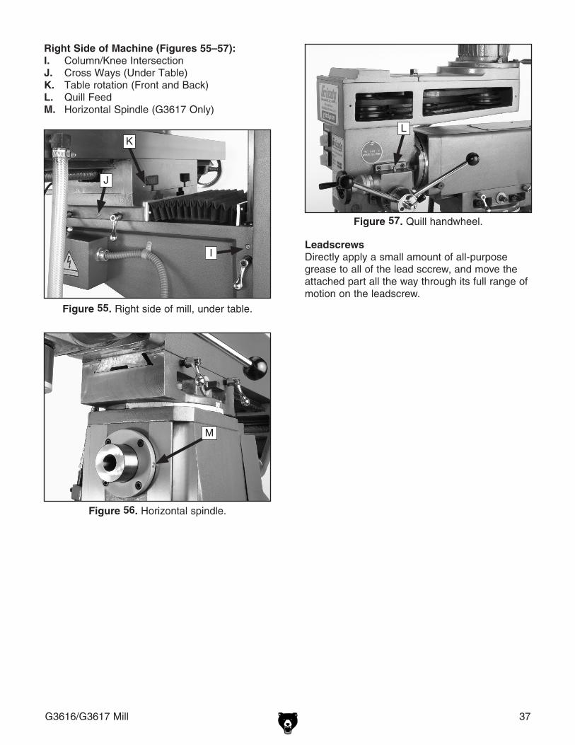
G3616/G3617 Mill 37
Figure 55. Right side of mill, under table.
Figure 56. Horizontal spindle.
Figure 57. Quill handwheel.
Right Side of Machine (Figures 55–57):I. Column/Knee IntersectionJ. Cross Ways (Under Table)K. Table rotation (Front and Back)L. Quill FeedM. Horizontal Spindle (G3617 Only)
J
K
I
M
L
LeadscrewsDirectly apply a small amount of all-purpose grease to all of the lead sccrew, and move the attached part all the way through its full range of motion on the leadscrew.
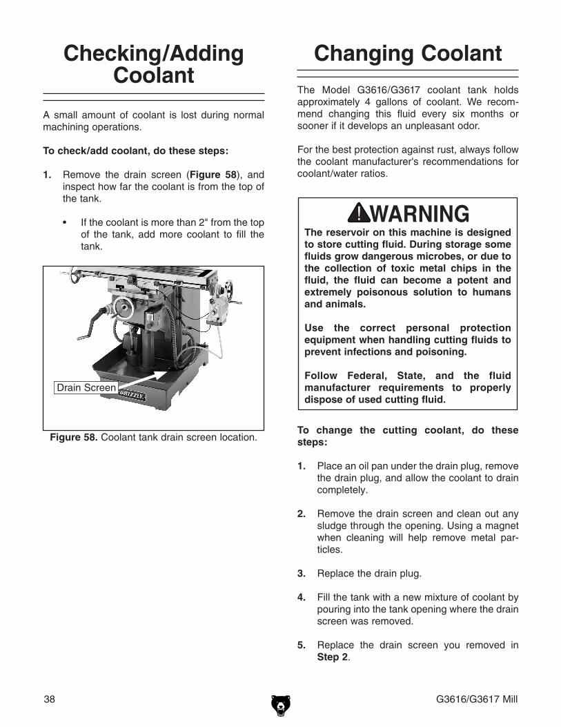
38 G3616/G3617 Mill
Changing CoolantThe Model G3616/G3617 coolant tank holds approximately 4 gallons of coolant. We recom-mend changing this fluid every six months or sooner if it develops an unpleasant odor.
For the best protection against rust, always follow the coolant manufacturer's recommendations for coolant/water ratios.
Checking/Adding Coolant
A small amount of coolant is lost during normal machining operations.
To check/add coolant, do these steps:
1. Remove the drain screen (Figure 58), and inspect how far the coolant is from the top of the tank.
• If the coolant is more than 2" from the top
of the tank, add more coolant to fill the tank.
Drain Screen
Figure 58. Coolant tank drain screen location.
The reservoir on this machine is designed to store cutting fluid. During storage some fluids grow dangerous microbes, or due to the collection of toxic metal chips in the fluid, the fluid can become a potent and extremely poisonous solution to humans and animals.
Use the correct personal protection equipment when handling cutting fluids to prevent infections and poisoning.
Follow Federal, State, and the fluid manufacturer requirements to properly dispose of used cutting fluid.
To change the cutting coolant, do these steps:
1. Place an oil pan under the drain plug, remove the drain plug, and allow the coolant to drain completely.
2. Remove the drain screen and clean out any sludge through the opening. Using a magnet when cleaning will help remove metal par-ticles.
3. Replace the drain plug.
4. Fill the tank with a new mixture of coolant by pouring into the tank opening where the drain screen was removed.
5. Replace the drain screen you removed in Step 2.
G3616/G3617 Mill 39
SECTION 7: SERVICE
Always disconnect power to the machine before performing ser-vice adjustments. Failure to do this may result in serious personal injury.
This section is designed to help the operator with adjustments that were made at the factory and that might also need to be made during the life of the machine.
This section is provided for your convenience—it is not a substitute for the Grizzly Service Department. If any adjustments arise that are not described in this manual, then feel free to call the Grizzly Technical Support at (570) 546-9663.
Similarly, if you are unsure of how to perform any procedure in this section, the Grizzly Technical Support personnel will be happy to guide you through the procedures or help in any other way.
About Service

40 G3616/G3617 Mill
TroubleshootingThis section covers the most common problems. WARNING! DO NOT make any adjust-ments until the mill is unplugged and all moving parts have come to a complete stop.
SYMPTOM POSSIBLE CAUSE CORRECTIVE ACTION
Machine does not start or breaker trips.
1. Emergency stop push-button is engaged, or is faulty.
2. Plug or receptacle is at fault or wired incorrectly.
3. Start capacitor is faulty.4. The thermal protection relay below
the motor contactor is tripped.
5. Contactor not getting energized or has burnt contacts.
6. Wall fuse or circuit breaker is blown or tripped.
7. Motor connection is wired incorrectly.
8. Power supply is faulty, or is switched OFF.
9. Electrical box door is open, or door safety switch is faulty.
10. Motor ON button or ON/OFF switch is faulty.
11. Centrifugal Switch is at fault.12. Spindle rotation switch at fault.13. Cable or wiring is open or has high
resistance.
14. Motor is at fault.
1. Rotate the button knob clockwise slightly until it pops out, or replace faulty emergency switch.
2. Test power plug and receptacle for good contact and correct wiring.
3. Test and replace capacitor as required.4. If no short exists, turn the cut-out dial on the relay
to increase working amps, and push the reset pin, or replace weak relay.
5. Test for power in and out on all legs, and contactor operation. Replace unit if faulty.
6. Make sure circuit breaker/fuse is sized correctly for machine load, or replace weak breaker.
7. Correct motor wiring.
8. Make sure all hot lines and grounds are operational and have correct voltage on all legs.
9. Close door, or replace faulty limit switch.
10. Replace faulty ON button or ON/OFF switch.
11. Adjust or replace the centrifugal switch if available.12. Turn switch to FWD or REV, or replace bad switch.13. Troubleshoot wires for internal or external breaks,
check for disconnected or corroded connections and repair or replace wiring.
14. Test, repair or replace motor.
Machine stalls or is underpowered.
1. Wrong workpiece material.
2. Incorrect spindle speed for task.3. Run capacitor is faulty.4. Low power supply voltage.
5. Belt(s) is slipping.
6. Motor bearings are at fault.
7. Machine is undersized for the task.
8. Motor has overheated.
9. Centrifugal switch is at fault.10. Motor is at fault.
1. Only process metal that has the correct properties for your type of machining.
2. Decrease spindle speed.3. Test/replace capacitor as required.4. Make sure all hot lines and grounds are operational
and have correct voltage on all legs.5. Replace bad belts as a matched set, align pulleys,
and re-tension.6. Rotate motor shaft for noisy or burnt bearings,
repair/replace as required.7. Use smaller sharp mill/cutters/drill bits, and reduce
the feed rate, reduce the spindle RPM, and use cutting fluid if possible.
8. Unobstructed motor cooling air flow, let motor cool, and reduce workload on machine.
9. Adjust or replace the centrifugal switch if available.10. Test, repair or replace motor.
Spindle starts, but coolant pump will not start.
1. Coolant pump relay tripped.2. Switch at fault.3. Pump damaged by running without
coolant present.
1. Press the reset button on the coolant pump relay.2. Replace switch.3. Replace pump.
Motor/Electrical

G3616/G3617 Mill 41
SYMPTOM POSSIBLE CAUSE CORRECTIVE ACTION
Tool slips in collet. 1. Collet is not fully drawn up into spindle taper.
2. Wrong size collet.
3. Debris in collet or in spindle taper.
4. Taking too big of a cut.
1. Snug up draw bar. 2. Measure tool shank diameter and match with
appropriate diameter collet.3. Remove all oil and debris from collet and spindle
taper.4. Lessen depth of cut and allow chips to clear.
Breaking tools or cutters. 1. RPM and or feed rate is too fast.2. Cutting tool getting too hot.3. Taking too big of a cut.
1. Use tables to set correct RPM and feed rates. 2. Use cutting fluid or oil for appropriate application.3. Lessen depth of cut and allow chips to clear.
Machine is loud when cutting. Overheats or bogs down in the cut.
1. Excessive depth of cut.2. Dull cutting tools.
1. Decrease depth of cut.2. Use sharp cutting tools.
Workpiece vibrates or chatters during operation.
1. Table locks not tight. 2. Spindle lock not tight.3. Workpiece not securely clamped to
table or into mill vise.4. RPM and feed rate too high.
1. Tighten down table locks.2. Tighten spindle lock.3. Check that clamping is tight and sufficient for the
job. Make sure mill vise is tight to the table.4. Use appropriate RPM and feed for the job.
Table hard to move. 1. Table locks are tightened down.2. Chips have loaded up on bedways.
3. Bedways are dry and in need of lubrication.
4. Longitudinal stops are interfering.
5. Gibs are too tight.
1. Check to make sure table locks are fully released.2. Frequently clean away chips that load up during
milling operations.3. Lubricate bedways and handles.
4. Check to make sure that stops are floating and not hitting the center stop.
5. Loosen gib screw(s))
Micro-feed adjuster won't lower the quill.
1. Quill knob is not tightened down 1. Turn the quill knob clockwise to tighten and engage the micro-feed adjuster.
Bad surface finish. 1. Wrong RPM or feed rate.2. Dull cutting tool or poor cutting tool
selection.3. Wrong rotation of cutting tool.
1. Adjust for appropriate RPM and feed rate.2. Sharpen cutting tool or select a better cutting tool
for the intended operation.3. Check for proper cutting rotation for cutting tool.
Machine Performance

42 G3616/G3617 Mill
4. Open the access panel to the V-belts.
5. Remove the front V-belt by moving the belt down the center pulley set and then up the front pulley set.
6. Remove the rear V-belt by moving the belt down both pulley sets.
7. Replace the rear V-belt first, by placing the belt under both pulley sets and then working up.
8. Replace the front V-belt by dropping the belt down over the front pulley set, through the opening in the top, and then working it under the center pulley set.
9. Move the V-belts to the desired RPM setting and tighten the nuts. Review Setting RPM on Page 22 for detailed instructions.
10. Replace the access cover and secure in place with the two thumb screws.
11. Replace the top cover and secure in place with the four Phillips head screws.
Replacing V-belts
When a V-belt is worn, cracked, or broken, it needs to be replaced. The following instructions are for belt replacement.
Vertical Spindle1. Loosen the motor nut and center pulley nut.
2. Pull the motor towards the front of the mill.
3. Remove the four Phillips head screws on the top cover (See Figure 59), and remove the cover.
Figure 59. Vertical spindle access area.
1. Loosen these nuts.
2. Pull handle towards front of
machine.
3. Remove four screws in this area.

G3616/G3617 Mill 43
Figure 60. Horizontal spindle access area.
Nut to Loosen/Tighten Tension
on V-Belts
Horizontal Spindle (G3617 Only)1. Open the access panel to the horizontal
spindle pulleys.
2. Loosen the bolt that holds the center pulley set (See Figure 60) in place. The bolt can be accessed through the opening next to the tension nut.
3. Remove the tension nut between the motor and the middle pulley sets to release tension on the V-belts.
4. Slide the center pulley set to the right to release tension and allow belt movement.
5. Remove the damaged V-belt and replace it. Note: The upper V-belt must be installed first.
6. Move the V-belts to the appropriate pulley sets for the needed RPM.
7. Move the center pulley set back into position and reinstall the tension nut, bring the pulleys to the proper tension.
8. Tighten the nut to secure the center pulley set.
9. Close the access cover by inserting the knob screw, then connect the machine to the power source.
Center Pulley Set
Spindle Tension Bolt
V-Belts Directly on Horizontal Spindle1. To replace the V-belts that are mounted on
the spindle, first complete Steps 1–4 from the Horizontal Spindle instructions.
2. Loosen the spindle tension bolt. Do not loos-en the nut (see Figure 60).
3. Pull the upper pulley set up to loosen tension on the spindle pulleys.
4. Remove the damaged V-belt and replace it.
5. Tighten spindle tension bolt.
6. Push the upper pulley set back into position.
7. Complete Steps 7–9 from the Horizontal Spindle instructions.

44 G3616/G3617 Mill
Adjusting Gibs
The gibs control the accuracy of the table move-ments. Tight gibs make the table movement more accurate, but harder to move. Loose gibs make the table movement sloppy, but easy to move.
Figure 61. Longitudinal gib location.
NOTICEWhen adjusting gibs, the goal of gib adjust-ment is to remove unnecessary sloppi-ness without causing the slides to bind. Loose gibs may cause poor finishes on the workpiece and may cause undue wear on the slide. Over-tightening may cause pre-mature wear.
Longitudinal Gib Adjustment Screw
Each sliding dovetail on the Model G3616/G3617 has a gib that is sandwiched between two adjust-ment screws (see Figures 61–64 for the locations of one end of each adjustment screw).
Some minor components must be removed to access all the gib adjustment screws.
Adjust the gibs by loosening one screw and tight-ening the other at the opposite end until a slight drag is felt while moving the table/knee along the dovetail slides; then tighten the loose screw at the other end to lock the setting in place.
Note: The G3617 spindle support adjusts along the dovetail slide by a clamping system.
Figure 63. Spindle head gib location.
Figure 62. Cross feed and knee feed gib locations.
Cross Feed Gib Adjustment Screw
Figure 64. Spindle support gib location.
Knee Feed Gib Adjustment Screw
Spindle Head Gib Adjustment Screw
Spindle Support Adjustment Screw

G3616/G3617 Mill 45
G3616 Wiring Box Identification
AC Contactor
Pump Capacitor
Circuit Breaker
Transformer
Main Power Switch
Grounding Terminal Bar
Main Terminal Bar
Vertical Spindle Relay
Coolant Pump Relay

46 G3616/G3617 Mill
G3616 110V Wiring Diagram
CODE NAME SPECIFICATIONS
M1 SINGLE-PHASE MOTOR (VERTICAL) YC1000L2-4 1PH 110V/220V 60HZ 2HP 1725 RPM V1
M2 COOLANT PUMP YDB-12TH 40W 1PH 110V/220V 60HZ 12L/MIN 3M
A1 POWER FEED AS-235 AC 110V
KM AC CONTACTOR CJX1-32/22 AC 24V 60HZ
QS MAIN POWER SWITCH HZ12-40/15
FR1 SPINDLE MOTOR RELAY JR16-20/3D DIAL SETTING:20A CURRENT RANGE: 20~32A
FR2 COOLANT PUMP MOTOR RELAY JR16-20/3D DIAL SETTING:0.9A CURRENT RANGE 0.68~1.1A
SA1 COMBINATION SWITCH FOR VERTICAL SPINDLE
HZ5C-25/M4D035
SA2 COMBINATION SWITCH FOR COOLANT PUMP
HZ5C-10/M2C005
SB EMERGENCY STOP BUTTON LAY3-02ZS/1 2NC
QF CIRCUIT BREAKER DZ47-63 (1P 3A)
TC TRANSFORMER JBK4-200 1:0-110V 0:0-110V/120VA 0-220V 0-24V/80VA
EL HALOGEN LAMP JC-38 (50W AC:24V)

G3616/G3617 Mill 47
G3616 220V Wiring Diagram
CODE NAME SPECIFICATIONS
M1 SINGLE-PHASE MOTOR (VERTICAL) YC1000L2-4 1PH 110V/220V 60HZ 2HP 1725 RPM V1
M2 COOLANT PUMP YDB-12TH 40W 1PH 110V/220V 60HZ 12L/MIN 3M
A1 POWER FEED AS-235 AC 110V
KM AC CONTACTOR CJX1-32/22 AC 24V 60HZ
QS MAIN SWITCH HZ12-40/15
FR1 RELAY JR16-20/3D DIAL SETTING:10A CURRENT RANGE: 10~16A
FR2 RELAY JR16-20/3D DIAL SETTING:0.45A CURRENT RANGE 0.32~0.5A
SA1 COMBINATION SWITCH FOR VERTICAL SPINDLE
HZ5C-25/M4D035
SA2 COMBINATION SWITCH FOR COOLANT PUMP
HZ5C-10/M2C005
SB EMERGENCY STOP BUTTON LAY3-02ZS/1 2NC
QF CIRCUIT BREAKER DZ47-63 (1P 3A)
TC TRANSFORMER JBK4-200 1:0-110V 0:0-110V/120VA 0-220V 0-24V/80VA
EL HALOGEN LAMP JC-38 (50W AC:24V)

48 G3616/G3617 Mill
G3617 Wiring Box Identification
Contactor
Vertical Spindle Relay
Pump Capacitor
Circuit Breaker
Main Switch
Transformer
Grounding Terminal Bar
Main Terminal Bar
Horizontal Spindle Relay
Coolant Pump Relay

G3616/G3617 Mill 49
G3617 110V Wiring Diagram
CODE NAME SPECIFICATIONS
M1 SINGLE-PHASE MOTOR (VERTICAL) YC1000L2-4 1PH 110V/220V 60HZ 2HP 1725 RPM V1
M2 SINGLE-PHASE MOTOR (HORIZONTAL) YC90L2-4 1PH 110V/220V 60HZ 1.5HP 1725 RPM B3
M3 COOLANT PUMP YDB-12TH 40W 1PH 110V/220V 60HZ 12L/MIN 3M
A1 POWER FEED AS-235 AC 110V
KM AC CONTACTOR CJX1-32/22 AC 24V 60HZ
QS MAIN POWER SWITCH HZ12-40/15
FR1 VERTICAL SPINDLE MOTOR RELAY JR16-20/3D DIAL: 25A CURRENT RANGE: 20-32A
FR2 HORIZONTAL SPINDLE MOTOR RELAY JR16-20/3D DIAL: 25A CURRENT RANGE: 20-32A
FR3 COOLANT PUMP MOTOR RELAY JR16-20/3D DIAL: 0.9A CURRENT RANGE 0.6~1.1A
SA1 COMBINATION SWITCH FOR VERTICAL SPINDLE HZ5C-25/M4D035v
SA2 COMBINATION SWITCH FOR HORIZONTAL SPINDLE
HZ5C-25/M4D035
SA3 COMBINATION SWITCH FOR COOLANT PUMP HZ5C-10/M2C005
SB EMERGENCY STOP BUTTON LAY3-02ZS/1 2NC
SQ MICRO SWITCH LXW6-11DL LE:3A
QF CIRCUIT BREAKER DZ47-63 (1P 3A)
TC TRANSFORMER JBK4-200 1:0-110V 0:0-110V/120VA 0-220V 0-24V/80VA
EL HALOGEN LAMP JC-38 (50W AC:24V)

50 G3616/G3617 Mill
G3617 220V Wiring Diagram
CODE NAME SPECIFICATIONS
M1 SINGLE-PHASE MOTOR (VERTICAL) YC1000L2-4 1PH 110V/220V 60HZ 2HP 1725 RPM V1
M2 SINGLE-PHASE MOTOR (HORIZONTAL) YC90L2-4 1PH 110V/220V 60HZ 1.5HP 1725 RPM B3
M3 COOLANT PUMP YDB-12TH 40W 1PH 110V/220V 60HZ 12L/MIN 3M
A1 POWER FEED AS-235 AC 110V
KM AC CONTACTOR CJX1-32/22 AC 24V 60HZ
QS MAIN SWITCH HZ12-40/15
FR1 VERTICAL SPINDLE MOTOR RELAY JR16-20/3D DIAL: 10A CURRENT RANGE: 10~16A
FR2 HORIZONTAL SPINDLE MOTOR RELAY JR16-20/3D DIAL: 8.5A CURRENT RANGE: 6.8~11A
FR3 COOLANT PUMP MOTOR RELAY JR16-20/3D DIAL: 0.45A CURRENT RANGE 0.32~0.5A
SA1 COMBINATION SWITCH FOR VERTICAL SPINDLE HZ5C-25/M4D035
SA2 COMBINATION SWITCH FOR HORIZONTAL SPINDLE
HZ5C-25/M4D035
SA3 COMBINATION SWITCH FOR COOLANT PUMP HZ5C-10/M2C005
SB EMERGENCY STOP BUTTON LAY3-02ZS/1 2NC
SQ MICRO SWITCH LXW6-11DL LE:3A
QF CIRCUIT BREAKER DZ47-63 (1P 3A)
TC TRANSFORMER JBK4-200 1:0-110V 0:0-110V/120VA 0-220V 0-24V/80VA
EL HALOGEN LAMP JC-38 (50W AC:24V)

G3616/G3617 Mill 51
Column Parts Breakdown
��
��
��
���
�
�
����
���� ��
����
��
����
��
��
��
��
��
��
��
��
����
��
��
��
��
��
��
��
�� ��
�� ��
��
����
����
��
��
��
��
����
������
��
����
��
��
��
��
��
����
����
�
����
�� ��
��
�� ��
�� ����
��
��
��
��
��
��
��
��
��
��
��
�
������
��

52 G3616/G3617 Mill
Column Parts ListREF PART # DESCRIPTION REF PART # DESCRIPTION1 P3616001 BASE 48 P3616048 WIPER PLATE2 P3616002 COLUMN (G3616) 49 P3616049 WIPER PLATE2 P3617002 COLUMN (G3617) 50 P3616050 WIPER PLATE3 P3616003 ELEVATING SCREW HOUSING 51 P3616051 KNEE4 PLW06M LOCK WASHER 10MM 52 P3616052 CLAMP BLOCK5 PB116M HEX BOLT M10-1.5 x 45 53 P3616053 CLAMP BOLT M10-1.5 x 58 X 256 P3616006 CONNECT TUBE 54 P3616054 HOIST DESCEND LEAD SCREW 7 PS38M PHLP HD SCR M4-.7 x 10 55 P3616055 CIRCULAR NUT8 PB131M HEX BOLT M16-2 X 65 56 P3616056 CONICAL GEAR9 PLW10M LOCK WASHER 16MM 57 PK95M KEY 6 X 6 X 1010 P3616010 COLLAR 58 P3616058 BALL BEARING 25 X 42 X 1111 PSB31M CAP SCREW M8-1.25 x 25 59 P3616059 ADJUST WASHER12 P3616012 HOLD SUPPORT 60 P3616060 COLLAR13 PSB77M CAP SCREW M12-1.75 X 30 61 P3616061 BALL BEARING 25 X 42 X 1114 P3616014 AROUND BRACKET 62 P3616062 HEX NUT DIA. 42 X 60MM15 P3616015 FEED SHAFT 63 PSS16M SET SCREW M8-1.25 X 10¹⁶ P3616016 COLLAR 64 PK09M KEY 8 X 8 X 3617 P3617017 CLAMP BOLT M12-1.75 X 58 X 25 65 P3616065 CONICAL GEAR18 P3616018 CLAMP BLOCK 66 PK34M KEY 5 X 5 X 2019 P3616019 GIB 67 PW19M FLAT WASHER 42 x 25 x 3MM20 PFH42M FLAT HD SCR M8-1.25 x 40 68 P3616068 COLLAR21 P3616021 OVERARM 69 PSS80M SET SCREW M8-1.25 x 1522 P3616022 COVER 70 P3616070 SHAFT23 PS08M PHLP HD SCR M5-.8 X 12 71 P3616071 COLLAR24 P3616024 COVER 72 PSB114M CAP SCREW M6-1 x 2225 PS08M PHLP HD SCR M5-.8 X 12 73 P3616073 BALL BEARING 25 X 42 X 1126 P3616026 HOLD BRACKET 74 P3616074 SCALE RING27 P3616027 GEAR 75 P3617075 KNURLED THUMB SCR M6-1 X 1028 PSB122M CAP SCREW M16-2 X 50 76 P3616076 COLLAR29 PSB123M CAP SCREW M16-2 X 60 77 P3616077 HANDLE30 P3616030 NOZZLE 78 P3617078 LIFT BAR (G3617)31 P3616031 OIL CUP 79 P3617079 TOOLHOLDER (G3617)32 PSB01M CAP SCREW M6-1 x 16 80 P3617080 CUTTER BAR COLLAR (G3617)33 PSB01M CAP SCREW M6-1 x 16 81 P3617081 SUPPORT (G3617)34 P3616034 CONNECT TUBE 82 P3617082 SPECIAL BOLT M16-2 X 218 (G3617)35 P3616035 HOLD BRACKET 83 P3617083 COLLAR (G3617)36 PN13M HEX NUT M16-2 84 P3617084 SPECIAL NUT M22 X 1.5MM (G3617)37 PLW10M LOCK WASHER 16MM 85 PSS06M SET SCREW M8-1.25 x 16 (G3617)38 P3616038 T BOLT M16-2 X 63 86 P3617086 OIL CUP (G3617)39 PS08M PHLP HD SCR M5-.8 X 12 87 PW08M FLAT WASHER 16MM (G3617)40 P3616040 ELECTRIC PUMP 88 PN13M HEX NUT M16-2 (G3617)41 PB83M HEX BOLT M6-1 X 16 89 P3617089 BEHIND COVER (G3617)42 P3616042 SUPPORT 90 P3617090 HINGE (G3617)43 P3616043 DUST COVER 91 PFH25M FLAT HD SCR M4-.7 X 12 (G3617)44 PS08M PHLP HD SCR M5-.8 X 12 92 PS96M PHLP HD SCR M10-1.5 x 8 (G3617)45 P3616045 GIB 93 P3616093 VERTICAL SPINDLE SPEEDS LABEL46 P3616046 ADJUST SCREW M8-1.25 94 P3617094 HORZ SPINDLE SPEEDS LABEL47 PS08M PHLP HD SCR M5-.8 X 12 95 G8588 GRIZZLY CAST IRON LOGO PLATE

G3616/G3617 Mill 53
Rotary Table Parts Breakdown
������
���
��� ���
���
���
���
���
���
��� ���
���
������
���
���
������
������
���
������
���
������
���
���
���
������
���
��� ���������������
������
������
���
���
���
���
���
������
���
���
���
���
���
���

54 G3616/G3617 Mill
Rotary Table Parts ListREF PART # DESCRIPTION REF PART # DESCRIPTION101 P3616101 HANDLE 127 P3616127 ADJUST SCREW M8-1.25102 P3616102 HANDLE COLLAR 128 P3616128 LONG LEAD SCREW (G3616)103 PN09M HEX NUT M12-1.75 128 P3617128 LONG LEAD SCREW (G3617)104 PK96M KEY 3 X 3 X 20 129 P3617129 WAY COVER105 PLW05M LOCK WASHER 12MM 130 PS68M SLOT SCREW M6-1 X 12106 P3616106 HAND WHEEL 131 P3616131 FLAT HD SCR M8-1.25 x 20107 P3616107 SCALE RING 132 P3616132 SPECIAL WASHER 32 X 9 X 1.5108 PSB04M CAP SCREW M6-1 X 10 133 P3616133 SADDLE109 P3616109 BALL BEARING 17 X 30 X 9 134 P3616134 CLAMP BOLT M10-1.5 x 58 X 25110 PSB61M CAP SCREW M10-1.5 x 20 135 P3616135 CARRIAGE CLAMP BLOCK111 P3616111 SUPPORT 136 P3616136 CLAMP BLOCK112 P3616112 OIL CUP 137 P3616134 CLAMP BOLT M10-1.5 x 58 X 25113 P3616113 SCREW BRACKET 138 PB03M HEX BOLT M8-1.25 X 16114 P3616114 DOG 139 P3616139 WIPER PLATE115 PSB01M CAP SCREW M6-1 X 16 140 PS08M PHLP HD SCR M5-.8 X 12116 P3616116 OIL CUP 141 P3617141 CROSS HEAD LEAD SCREW117 P3617117 ROTARY BRACKET 142 P3616142 GIB118 P3616118 TABLE (G3616) 143 P3617143 SPECIAL NUT 1"118 P3617118 TABLE (G3617) 144 P3616144 ADJUST SCREW M8-1.25119 P3616119 SPECIAL NUT 1" (LEAD NUT) 145 P3617145 BALL BEARING 17 X 30 X 9120 P3617120 LIMIT ASSEMBLY 146 P3616146 SUPPORT121 PN09M HEX NUT M12-1.75 147 PSB02M CAP SCREW M6-1 x 20122 PW06M FLAT WASHER 12MM 148 P3616148 OIL COVER123 P3616123 T BOLT M12-1.75 X 45 149 PS05M PHLP HD SCR M5-.8 x 8124 P3616124 SHAFT MOUNT 150 P3616150 CONNECT TUBE125 P3616125 SHAFT 151 P3616151 COMPLETE MILLING VISE126 P3616126 GIB
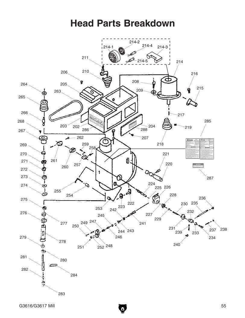
G3616/G3617 Mill 55
Head Parts Breakdown
���
���
���
���
���
���
���
���
���
���
���
���
���
���
������
������
������
���
���
������
���
���
��� ������
���
���
���
������
���
������
��� ������
���
���
������
���
���
���
���������
������
���
���
���
���
���
���
���
���
���
���
���
���
���
���
���
������ ���
���
������
���
���
���
������
������
���������
���
����������
�����
����������

56 G3616/G3617 Mill
Head Parts ListREF PART # DESCRIPTION REF PART # DESCRIPTION201 P3616201 SPINDLE BOX 243 P3616243 SMALL COVER202 P3616202 MOTOR BASE 244 PSB26M CAP SCREW M6-1 X 12203 P3616203 LEFT COVER 245 P3616245 BALL BEARING 15 X 28 X 9204 P3616204 RIGHT COVER 246 P3616246 COLLAR205 P3616205 PULLEY COVER 247 P3616247 SCALE RING206 PS26M SLOT HEAD SCREW M6-1 x 20 248 P3617248 HANDLE WHEEL207 P3616207 KNURLED SCREW M6-1 X 10 249 P3617249 HANDLE COLLAR208 PB74M HEX BOLT M10-1.5 x 20 250 P3617250 HANDLE209 PLW06M LOCK WASHER 10MM 251 PN26M ACORN NUT M12-1.75210 P3616210 CENTER PULLEY 252 PK97M KEY 4 X 4 X 14211 P3616211 CENTER PULLEY SHAFT 253 P3616253 CLAMP BLOCK212 PB07M HEX BOLT M8-1.25 x 25 254 P3616254 CLAMP BLOCK213 PW10M FLAT WASHER 14MM 255 P3616255 CLAMP HANDLE214 P3616214 MOTOR 257 P3616257 SPRING SEAT214-1 P3616214-1 MOTOR FAN COVER 258 PS11M SCREW M6-1 X 16214-2 P3616214-2 MOTOR FAN 259 PSS19M SET SCREW M8-1.25 x 30214-3 P3616214-3 CAPACITOR BOX 260 P3616260 SPRING PLATE214-4 PC150A S CAPACITOR 150MFD 250VAC 261 P3616261 SPRING CAP214-5 PC20A R CAPACITOR 20MFD 400VAC 262 PS17M PHLP HD SCR M4-.7 x 6215 P3616215 HANDLE 263 PVB30 V-BELT B-30 5L300216 PB07M HEX BOLT M8-1.25 x 25 264 P3616264 SLOTTED LOCK NUT M50 X 1.5MM217 PK41M KEY 8 X 8 X 40 265 P3616265 SPINDLE PULLEY218 P3616218 MOTOR PULLEY 266 P3616266 SPRING SLEEVE219 PSS04M SET SCREW M6-1 X 12 267 P3616267 COLLAR220 P3616220 WORM GEAR 268 PSB01M CAP SCREW M6-1 X 16221 PSB13M CAP SCREW M8-1.25 x 30 269 PR67M INT RETAINING RING 75MM222 P3616222 T BOLT M16-2 X 63 270 P6009ZZ BALL BEARING 6009ZZ223 PN13M HEX NUT M16-2 271 P3616271 COLLAR224 P3616224 FEED SHAFT 272 P6009ZZ BALL BEARING 6009ZZ225 PK09M KEY 8 X 8 X 36 273 PR67M INT RETAINING RING 75MM226 P3616226 HANDLWHEEL GEAR BOX 274 PR56M EXT RETAINING RING 45MM227 PSB14M CAP SCREW M8-1.25 x 20 275 P3616275 PULLEY NUT228 P3616228 BEVEL GEAR 276 PLW13M LOCK WASHER 40MM229 PR15M EXT RETAINING RING 30MM 277 P6003 BALL BEARING 6003ZZ230 P3616230 COMPRESSION SPRING 278 P3616278 QUILL231 P3616231 SCALE RING 279 P3616279 BALL BEARING 50 X 80 X 20232 P3616232 HANDLE BRACKET HUB 280 P3616280 DUST COVER233 P3616233 COVER 281 P3616281 SPINDLE234 PB133M HEX BOLT M16-2 X 90 282 P3616282 ARBOR R-8 X 235 P3617235 HANDLE BAR 283 P3616283 DRILL CHUCK236 P3617236 FEED SHAFT KNOB M12-1.75 284 P3616284 WEDGE SHIFTER237 P3616237 HANDLE 285 P3616285 G3616 MACHINE ID LABEL238 P3616238 HANDLE COLLAR KNOB 285 P3617285 G3617 MACHINE ID LABEL239 P3616239 SCALE 286 P3616286 SECONDARY WARNINGS LABEL240 P3616240 RIVET 287 P3616287 PROPER TRAINING NOTICE241 P3616241 WORM GEAR 288 P3616288 BELT GUARD LABEL242 P3616242 BALL BEARING 15 X 28 X 9

G3616/G3617 Mill 57
G3617 Horizontal Spindle Parts Breakdown
������
���
���
���
����������
����������
�����
�����
���
���
������
������
������
���
���
���
���
������
���
������
������
���
���
���
���
������
���
���
���
���
���
���
���
��� ���
������
���
������
���
������
������
������
������
���
��� ���
���
���
������
���
���
���
���
�����
�����
�����
�����
�����
�����
�����

58 G3616/G3617 Mill
G3617 Horizontal Spindle Parts ListREF PART # DESCRIPTION REF PART # DESCRIPTION303 PSB31M CAP SCREW M8-1.25 x 25 343 PN13M HEX NUT M16-2304 P3617304 OIL CUP 344 PW08M FLAT WASHER 16MM305 P3617305 COVER 345 PW08M FLAT WASHER 16MM306 P3617306 SPINDLE 346 P3617346 SMALL SHAFT307 P3617307 BALL BEARING 55 X 90 X 23 347 P3617347 CONNECT308 P3617308 COLLAR 349 P6003 BALL BEARING 6003ZZ309 P3617309 BALL BEARING 40 X 90 X 25 350 P3617350 COLLAR310 P3617310 SPECIAL WASHER 52 X 4 351 P6003 BALL BEARING 6003ZZ311 P3617311 FLAT WASHER 39MM 352 PR18M EXT RETAINING RING 17MM312 P3617312 SLOTTED LOCK NUT M39 X 1.5MM 353 PR21M INT RETAINING RING 35MM313 P3617313 COVER 354 P3617354 PULLEY314 PSB31M CAP SCREW M8-1.25 x 25 355 PVA31 V-BELT A-31 4L310315 P3617315 OIL CUP 356 P3617356 ADJUST SCREW M8-1.25316 P3617316 SPINDLE PULLEY 357 P3617357 SUPPORT317 PK90M KEY 10 X 10 X 25 358 PSB02M CAP SCREW M6-1 x 20318 PR12M EXT RETAINING RING 35MM 359 P3617359 SPECIAL NUT M8-1.25319 PVA30 V-BELT A-30 4L300 360 P3617360 MOTOR320 PK42M KEY 6 X 6 X 30 360-1 P3617360-1 MOTOR FAN COVER321 PR09M EXT RETAINING RING 20MM 360-2 P3617360-2 MOTOR FAN322 P3617322 WHEEL 360-3 P3617360-3 R CAPACITOR COVER323 P6003 BALL BEARING 6003ZZ 360-4 PC020B R CAPACITOR 20MFD 450VAC324 P3617324 BEARING 37MM 360-5 P3617360-5 S CAPACITOR COVER325 P6003 BALL BEARING 6003ZZ 360-6 PC150A S CAPACITOR 150MFD 250VAC326 P3617326 COLLAR 360-7 P3617360-7 WIRING BOX328 P3617328 SMALL SHAFT 361 PLW04M LOCK WASHER 8MM329 P3617329 COLLAR 362 PB07M HEX BOLT M8-1.25 x 25330 P3617330 SUPPORT 363 P3617363 MOTOR WHEEL331 PSB02M CAP SCREW M6-1 x 20 364 PSS04M SET SCREW M6-1 X 12332 PB13M HEX BOLT M10-1.5 x 80 365 PK43M KEY 8 X 8 X 45333 PN02M HEX NUT M10-1.5 366 PVA31 V-BELT A-31 4L310334 PR25M INT RETAINING RING 47MM 385 P3617385 1" HORIZONTAL ARBOR335 PR11M EXT RETAINING RING 25MM 385-1 P3617385-1 1" ARBOR NUT336 P3617336 SPECIAL NUT M64 X 2 385-2 P3617385-2 1" ARBOR SLEEVE337 PR25M INT RETAINING RING 47MM 385-3 P3617385-3 1" ARBOR SPACER338 P3617338 PULLEY 386 P3617386 1-1/4" HORIZONTAL ARBOR339 PR11M EXT RETAINING RING 25MM 386-1 P3617386-1 1-1/4" ARBOR NUT340 P3617340 KEY 8 X 8 X 50 386-2 P3617386-2 1-1/4" ARBOR SLEEVE341 P3617341 MOTOR BASE 386-3 P3617386-3 1-1/4" ARBOR SPACER342 PSB124M CAP SCREW M12-1.75 X 80

G3616/G3617 Mill 59
Power Feed Parts Breakdown
��������������� ���
���
��������
���
������
��������
����������
�����
�������������
������������������������������
�����
���
���
���
���
���
���
���
���
����������
��������
��������
���
���
���
������
�����
����������
�����
���
�����
��������������
���
������
������
�����
���
����������
������
���������������������
�����
�����
���
���
����������
������
���
������������
����������
������������
�����
���
����������������
����������
������������
����������
�����
�����������
�����
�����
�����
�����
�����
�����
��������
�����
���
���
��������
��������
��������
�����
���
���
���
���
���
���������������

60 G3616/G3617 Mill
Power Feed Parts List
REF PART # DESCRIPTION REF PART # DESCRIPTION401 P3616401 TOP HOUSING 501-5 PS95M PHLP HD SCR M3-.5 X 30402 PN20M HEX NUT M32-2 501-6 PN07M HEX NUT M3-.5403 PW20M FLAT WASHER 35MM 501-7 P3616501-7 CAPACITOR404 P3616404 BEVEL GEAR 502-1 P3616502-1 CAM ASSEMBLY405 PW08M FLAT WASHER 16MM 502-2 PRP11M ROLL PIN 2.5 X 16406 PLN09 LOCK NUT M12-1.75 503-1 P3616503-1 MOTOR FIELD ASSEMBLY407 P3616407 INNER RING 20/28 503-2 P3616503-2 ARMATURE ASSEMBLY408 P3616408 NEEDLE BEARING 504 P3616504 BRUSH409 P3616409 CIRCUIT BREAKER SUPPORT 505 P3616505 LIMIT SWITCH ASSEMBLY409-1 P3616409-1 CIRCUIT BREAKER 505-1 P3616505-1 HOLD PLATE409-2 P3616409-2 CIRCUIT BREAKER COVER 505-1 PN07M HEX NUT M3-.5409-3 PN09M HEX NUT M12-1.75 505-11 PS97M PHLP HD SCR M3-.5 X 34410 P3616410 BUSHING BEARING 505-12 PS98M PHLP HD SCR M3-.5 X 16411 P3616411 LIGHT TRANSMITTER 505-13 PS59M PHLP HD SCR M3-.5 X 14412 P3616412 HEX SEAL BOOT 505-14 P3616505-14 MICRO SWITCH413 PN09M HEX NUT M12-1.75 505-15 P3616505-15 CRESCENT RING414 P3616414 LIFT FORK SHAFT 505-2 P3616505-2 LIMIT SWITCH HOLDER415 P3616415 CRESCENT RING 505-3 P3616505-3 LIMIT PLATE416 P3616416 BUSHING BEARING 505-4 P3616505-4 ACTUATOR417 P3616417 BOTTOM HOUSING 505-5 P3616505-5 SPRING418 P3616418 SPECIAL SCREW 505-6 P3616505-6 LIMIT SWTCH GASKET419 P3616419 POWER CORD 505-7 P3616505-7 ACTUATOR420 P3616420 CONTROL CORD 505-8 P3616505-8 CONNECTING PLATE421 P3616421 CORD CLAMP 505-9 PS12M PHLP HD SCR M3-.5 X 6 422 P3616422 LOCKING NUT 506 P3616506 BRUSH HOLDER423 P3616423 BOTTOM COVER 506-1 P3616506-1 BRUSH CAP424 PS38M PHLP HD SCR M4-.7 X 10 507 P3616507 ON/OFF NAMPLATE425 PN04M HEX NUT M4-.7 508 P3616508 MICRO SWITCH ASSEMBLY426 PS17M PHLP HD SCR M4-.7 X 6 508-1 P3616508-1 MICRO SWITCH HOLDER427 P3616427 ADAPTOR 508-2 P3616508-2 MICRO SWITCH428 P3616428 SPRING FOR TOP HOUSING 508-3 PN07M HEX NUT M3-.5429 P3616429 BEARING MOUNT 508-4 PS59M PHLP HD SCR M3-.5 X 14430 PLW02M LOCK WASHER 4MM 509 P3616509 DRIVE GEAR ASSEMBLY431 PRP76M ROLL PIN 4 X 16 509-1 P3616509-1 DRIVE GEAR SHAFT432 PSS79M SET SCREW M4-.7 X 6 509-2 PRP37M ROLL PIN 3 X 14433 P3616433 LABEL 509-3 P80018 BALL BEARING 80018434 P3616434 ON/OFF SWITCH 509-4 P3616509-4 DRIVE GEAR434-1 PN09M HEX NUT M12-1.75 509-5 P3616509-5 SPACER435 P3616435 CAP OF ON/OFF SWITCH 509-6 PR66M INT RETAINING RING 25MM436 PN09M HEX NUT M12-1.75 510 P3616510 LIFT FORK ASSEMBLY437 P3616437 CAUTION LABEL 510-1 P3616510-1 DRIVING SHAFT438 P3616438 LABEL 510-2 P3616510-2 SHAFT MOUNT439 P3616439 LABEL 510-3 P3616510-3 SPRING440 PS94M PHLP HD SCR M5-.8 X 75 510-4 P3616510-4 CLUTCH501 P3616501 MICRO SWITCH ASSY 510-5 PW18M FLAT WASHER 18MM501-1 P3616501-1 MICRO SWITCH HOLDER 510-6 P3616510-6 BEARING COVER501-2 P3616501-2 SWITCH ACTUATOR 510-7 P3616510-7 BEARING501-3 P3616501-3 PIN ACTUATOR 510-8 PRP02M ROLL PIN 3 X 16501-4 P3616501-4 MICRO SWITCH 510-9 PRP02M ROLL PIN 3 X 16

G3616/G3617 Mill 61
Power Feed Parts List, continued
REF PART # DESCRIPTION REF PART # DESCRIPTION511-1 P3616511-1 LIFTFORK 515-2 P3616515-2 RAPID SWITCH HOUSING511-2 P3616511-2 LIFTFORK RING 515-3 P3616515-3 SPRING FOR RAPID SWITCH511-3 P3616511-3 PIN, LIFTFORK RING 3 X 14 515-4 PEC13M E-CLIP 5MM512-1 P3616512-1 X CONTROL HANDLE ASSY 516 P3616516 CIRCUIT BOARD ASSEMBLY512-2 P3616512-2 Y,Z CONTROL HANDLE ASSY 517 P3616517 CIRCUIT BOARD INSULATOR512-3 P3616512-3 HANDLE KNOB M8-1.25 518 P3616518 TRAVEL STOP ASSEMBLY512-4 PSS04M SET SCREW M6-1 X 12 518-1 P3616518-1 TRAVEL STOP512-5 P3616512-5 CONTROL HANDLE 518-2 P3616518-2 TRAVEL STOP BASE513 P3616513 ZYTEL GEAR ASSEMBLY 518-3 P3616518-3 TRAVEL STOP SHAFT513-1 P3616513-1 ZYTEL GEAR WITHOUT HUB 518-4 P3616518-4 SPRING513-2 PW21M FLAT WASHER 32MM 518-5 PB07M HEX BOLT M8-1.25 X 25513-3 P3616513-3 HUB OF ZYTEL GEAR 518-6 P3616518-6 SPACER513-4 P3616513-4 LOCK WASHER 38MM 518-7 PR39M EXT RETAINING RING 8MM513-5 PR29M INT RETAINING RING 32MM 519 P3616519 SPEED CONTROL KNOB ASSEMBLY514-1 P3616514-1 POTENTIOMETER ASSEMBLY 519-1 P3616519-1 SPEED CONTROL KNOB M6-1514-2 P3616514-2 POTENTIOMETER RING 519-2 P3616519-2 SPEED CONTROL LABEL514-3 P3616514-3 POTENTIOMETER SARAIN 519-3 PSS49M SET SCREW M4-.7 X 16514-4 PW05M FLAT WASHER 4MM 512-1-1 P3616512-1-1 X CONTROL HANDLE DISC514-5 PS17M PHLP HD SCR M4-.7 X 6 512-1-2 P3616512-1-2 Y,Z CONTROL HANDLE DISC515 P3616515 RAPID SWITCH BUTTON 514-1-1 PN03M HEX NUT M8-1.25515-1 P3616515-1 RAPID SWITCH PLUNGER 514-1-2 P3616514-1-2 POTENTIOMETER WASHER

62 G3616/G3617 Mill
G3616 Electrical Parts Breakdown
���
����������
����������
���
���
������
������
���
���
���
���
���
���
���
���
��� ���
���
������
���
���
���
���
���
���
���
���
���
���
���
���
���
��� ���
������
���
���
���
���
���
���

G3616/G3617 Mill 63
G3616 Electrical Parts ListREF PART # DESCRIPTION REF PART # DESCRIPTION601 P3616601 HALOGEN LAMP 620 P3616620 E-STOP BUTTON LAY3-02ZS/1601-1 P3616601-1 BULB 621 P3616621 MAIN WIRING BOX W/LATCH601-2 P3616601-2 BULB COVER 622 PSB33M CAP SCREW M5-.8 X 12601-3 P3616601-3 BULB COVER RETAINER 623 P3616623 ELECTRICAL BOARD601-4 PS55M PHLP HD SCR M3-.5 X 10 624 PS09M PHLP HD SCR M5-.8 X 10602 PSB01M CAP SCREW M6-1 x 16 625 P3616625 CONTACTOR CJX1-32/22 24V603 P3616603 LAMP MOUNTING BRACKET 626 P3616626 RELAY JR16-20/3D 10-16A 220V604 PLW03M LOCK WASHER 6MM 626A P3616626A RELAY JR16-20/3D 20-32A 110V605 PN01M HEX NUT M6-.8 627 P3616627 RELAY JR16-20/3D 0.32-0.5A 220V606 PSB01M CAP SCREW M6-1 x 16 627A P3616627A RELAY JR16-20/3D 0.68-1.1A 110V607 PLW01M LOCK WASHER 5MM 628 P3616628 CIRCUIT BREAKER DZ47-63(1P,3A)608 P3616608 CONDUIT 20MM 629 P3616629 LARGE TERMINAL BAR609 P3616609 CONDUIT 15MM 630 P3616630 MICRO SWITCH610 P3616610 STRAIN RELIEF 20MM 631 P3616631 SMALL TERMINAL BAR611 P3616611 STRAIN RELIEF 25MM 632 P3616632 TRANSFORMER612 P3616612 VERTICAL SWITCH BOX COVER 633 P3616633 MAIN SWITCH W/KNOB613 PFH31M FLAT HD SCR M4-.7 X 8 634 P3616634 STRAIN RELIEF 6.5MM614 PS08M PHLP HD SCR M5-.8 X 12 635 P3616635 STRAIN RELIEF 15MM615 PLW01M LOCK WASHER 5MM 636 P3616636 STRAIN RELIEF 13MM616 PW02M FLAT WASHER 5MM 637 P3616637 CONDUIT 10MM617 P3616617 VERTICAL SWITCH BOX 638 PLABEL-14 ELECTRICITY LABEL618 P3616618 VERT SPINDLE SWITCH M4D035 650 P3616650 110V CONVERSION KIT619 P3616619 COOLANT PUMP SWITCH M2C005

64 G3616/G3617 Mill
G3617 Electrical Parts Breakdown
���
����������
����������
���
���
������
������
���
���
���
���
���
���
��� ���
���
���
���
���
������
���
���
��� ���
������
���
���
���
���
���
���
���
���
���
���
���
���
��� ���
������
���
���
���
���
���
������
������
���

G3616/G3617 Mill 65
G3617 Electrical Parts ListREF PART # DESCRIPTION REF PART # DESCRIPTION601 P3616601 HALOGEN LAMP 626 PSB33M CAP SCREW M5-.8 X 12601-1 P3616601-1 BULB 627 PS07M PHLP HD SCR M4-.7 X 8601-2 P3616601-2 BULB COVER 628 P3617628 HORZ SWITCH BOX COVER601-3 P3616601-3 BULB COVER RETAINER 629 P3616618 HORIZ SPINDLE SWITCH M4D035601-4 PS55M PHLP HD SCR M3-.5 X 10 630 P3616620 E-STOP BUTTON LAY3-02ZS/1602 PSB33M CAP SCREW M5-.8 X 12 631 PLW01M LOCK WASHER 5MM603 P3616603 LAMP MOUNTING BRACKET 632 PS09M PHLP HD SCR M5-.8 X 10604 P3616604 LOCK WASHER 5MM 633 P3617633 ELECTRICAL BOARD605 PN06M HEX NUT M5-.8 634 PS09M PHLP HD SCR M5-.8 X 10606 P3616606 CAP SCREW M5 635 P3616625 CONTACTOR CJX1-32/22 24V607 PLW01M LOCK WASHER 5MM 636 P3617626 RELAY JR16-20/3D 10-16A 220V608 P3616608 CONDUIT 20MM 636A P3616626A RELAY JR16-20/3D 20-32A 110V609 P3616609 CONDUIT 15MM 637 P3616637 RELAY JR16-20/3D 6.8-11A 220V610 P3616610 STRAIN RELIEF 20MM 637A P3616626A RELAY JR16-20/3D 20-32A 110V611 P3616611 STRAIN RELIEF 25MM 638 P3616627 RELAY JR16-20/3D 0.32-0.5A 220V612 P3616612 VERTICAL SWITCH BOX COVER 638A P3616627A RELAY JR16-20/3D 0.68-1.1 110V613 PFH31M FLAT HD SCR M4-.7 X 8 639 P3616629 LARGE TERMINAL BAR614 PS08M PHLP HD SCR M5-.8 X 12 640 P3616630 MICRO SWITCH615 PLW01M LOCK WASHER 5MM 641 P3616631 SMALL TERMINAL BAR616 PW02M FLAT WASHER 5MM 642 P3616632 TRANSFORMER617 P3617617 VERTICAL SWITCH BOX 643 P3616633 MAIN SWITCH W/KNOB618 P3616618 VERT SPINDLE SWITCH M4D035 644 P3616634 STRAIN RELIEF 6.5MM619 P3616619 COOLANT PUMP SWITCH M2C005 645 P3616635 STRAIN RELIEF 15MM620 P3616609 CONDUIT 15MM 646 P3616636 STRAIN RELIEF 13MM621 P3616610 STRAIN RELIEF 20MM 647 P3616637 CONDUIT 10MM622 P3617622 HORIZONTAL SWITCH BOX 648 P3616628 CIRCUIT BREAKER DZ47-63(1P,3A)623 P3616623 MAIN WIRING BOX W/LATCH 649 PLABEL-14 ELECTRICITY LABEL624 PW02M FLAT WASHER 5MM 650 P3617650 110V CONVERSION KIT625 PLW01M LOCK WASHER 5MM

66 G3616/G3617 Mill

CU
T A
LON
G D
OT
TE
D L
INE
Name _____________________________________________________________________________
Street _____________________________________________________________________________
City _______________________ State _________________________ Zip _____________________
Phone # ____________________ Email ________________________ Invoice # _________________
Model # ____________________ Order # _______________________ Serial # __________________
WARRANTY CARD
The following information is given on a voluntary basis. It will be used for marketing purposes to help us develop better products and services. Of course, all information is strictly confidential.
1. How did you learn about us? ____ Advertisement ____ Friend ____ Catalog ____ Card Deck ____ Website ____ Other:
2. Which of the following magazines do you subscribe to?
3. What is your annual household income? ____ $20,000-$29,000 ____ $30,000-$39,000 ____ $40,000-$49,000 ____ $50,000-$59,000 ____ $60,000-$69,000 ____ $70,000+
4. What is your age group? ____ 20-29 ____ 30-39 ____ 40-49 ____ 50-59 ____ 60-69 ____ 70+
5. How long have you been a woodworker/metalworker? ____ 0-2 Years ____ 2-8 Years ____ 8-20 Years ____20+ Years
6. How many of your machines or tools are Grizzly? ____ 0-2 ____ 3-5 ____ 6-9 ____10+
7. Do you think your machine represents a good value? _____Yes _____No
8. Would you recommend Grizzly Industrial to a friend? _____Yes _____No
9. Would you allow us to use your name as a reference for Grizzly customers in your area? Note: We never use names more than 3 times. _____Yes _____No
10. Comments: _____________________________________________________________________
_________________________________________________________________________________
_________________________________________________________________________________
_________________________________________________________________________________
____ Cabinet Maker____ Family Handyman____ Hand Loader____ Handy____ Home Shop Machinist____ Journal of Light Cont.____ Live Steam____ Model Airplane News____ Modeltec____ Old House Journal
____ Popular Mechanics____ Popular Science____ Popular Woodworking____ Practical Homeowner____ Precision Shooter____ Projects in Metal____ RC Modeler____ Rifle____ Shop Notes____ Shotgun News
____ Today’s Homeowner____ Wood____ Wooden Boat____ Woodshop News____ Woodsmith____ Woodwork____ Woodworker West____ Woodworker’s Journal____ Other:

TAPE ALONG EDGES--PLEASE DO NOT STAPLE
FOLD ALONG DOTTED LINE
FOLD ALONG DOTTED LINE
GRIZZLY INDUSTRIAL, INC.P.O. BOX 2069BELLINGHAM, WA 98227-2069
PlaceStampHere
Name_______________________________
Street_______________________________
City______________State______Zip______
Send a Grizzly Catalog to a friend:

Grizzly Industrial, Inc. warrants every product it sells for a period of 1 year to the original purchaser from the date of purchase. This warranty does not apply to defects due directly or indirectly to misuse, abuse, negligence, accidents, repairs or alterations or lack of maintenance. This is Grizzly’s sole written warranty and any and all warranties that may be implied by law, including any merchantability or fitness, for any par-ticular purpose, are hereby limited to the duration of this written warranty. We do not warrant or represent that the merchandise complies with the provisions of any law or acts unless the manufacturer so warrants. In no event shall Grizzly’s liability under this warranty exceed the purchase price paid for the product and any legal actions brought against Grizzly shall be tried in the State of Washington, County of Whatcom.
We shall in no event be liable for death, injuries to persons or property or for incidental, contingent, special, or consequential damages arising from the use of our products.
To take advantage of this warranty, contact us by mail or phone and give us all the details. We will then issue you a “Return Number,’’ which must be clearly posted on the outside as well as the inside of the carton. We will not accept any item back without this number. Proof of purchase must accompany the merchandise.
The manufacturers reserve the right to change specifications at any time because they constantly strive to achieve better quality equipment. We make every effort to ensure that our products meet high quality and durability standards and we hope you never need to use this warranty.
Please feel free to write or call us if you have any questions about the machine or the manual.
Thank you again for your business and continued support. We hope to serve you again soon.
WARRANTY AND RETURNS

�����������������������������������������������������������������������
����
�����������������
��������������������������������
���������������������������������
�������������������������������������������������������������������������
���������������������������������������