Microwave/Millimeter Wave Technology Engineering Center in B-1.pdf · Microwave/Millimeter Wave...
70
Jianxun Wang Microwave/Millimeter Wave Technology Engineering Center Dept of Physical Electronics University of Electronic Science and Technology, Cheng Du, China
Transcript of Microwave/Millimeter Wave Technology Engineering Center in B-1.pdf · Microwave/Millimeter Wave...

Jianxun Wang
Microwave/Millimeter Wave Technology Engineering Center
Dept of Physical Electronics University of Electronic Science and
Technology, Cheng Du, China

Outline
What is MVED? Different kinds of MVED MVED Applications Then, now and Future of MVED MVED Research in UESTC

What is MVED?
Microwave Power: kW~GW
Input signal: few mw ~ several w, several MHz~ THz
Microwave vacuum electronic devices utilize free electrons in a vacuum to convert energy from a dc power source to an RF signal.
MVEDs: Linear buching, angular bunching and etc.
DC Power supply: few ~ hundreds kV , several mA ~ thousands A, CW or Pulsed
Since the vacuum vane like a tube, MVED usually be called microwave "tubes". The process of energy conversion from dc electron beam to microwave power is beam wave interaction.

Different kinds of MVED

Tube Type Frequency
———————— Bandwidth
Power Out (Typical)
Attributes ——————————
Drawbacks Applications
klystron 0.1-300GHz
———————— 5%-10%
10Kw CW
10Mw Pluse
High Power 40%-60% Efficient
Low Noise ——————————
Narrow bandwidth
Radar Television Industrial Heating Satellite Uplinks Medical Therapy
Science
Traveling Wave Tube(Helix)
1-90GHz ————————Wide bandwith 2-3
octaves+
20w CW and
20Kw Pluse
Broad bandwidth ——————————
Power Handling Limitations Efficiency
Electronic Warfare Communications
Broadcasting Industrial Applications
Coupled Cavity TWT
1-200GHz ————————
10%-20%
300w CW 250Kw Pluse
Average Power Capability —————————— Complex & Expensive Slow Wave Structure
Airborne Radar Satellite
Communications
Magnetron 1-90GHz
———————— N/A
100w CW 10Mw Pluse
Simple-Inexpensive 80% High Efficiency
—————————— Noisy
Radar/Medical Industrial Heating
Cross Field Amplifier
1-30GHz ————————
10-20%
1000w CW 5Mw Pluse
Compact Size 30%-40% Efficient
—————————— Complex & Expensive Slow Wave Structure
Transportable Radars Shipboard Radar Seeker Radars
Industial Heating
Gyrotron 30-200GHz
———————— 10% max
0.2-3Mw Pluse
High Power @ High frequenies
—————————— Supper Conductor Requested
High Frequency Radar Fussion
Accelerators Industrial Heating
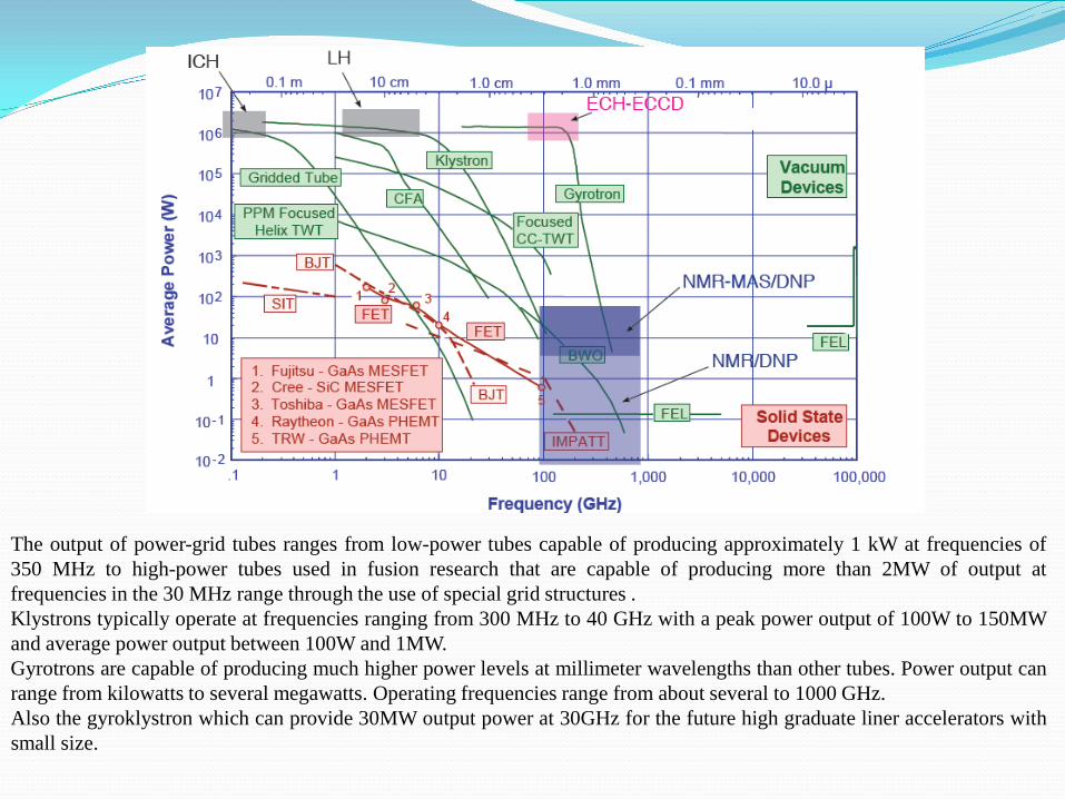
The output of power-grid tubes ranges from low-power tubes capable of producing approximately 1 kW at frequencies of 350 MHz to high-power tubes used in fusion research that are capable of producing more than 2MW of output at frequencies in the 30 MHz range through the use of special grid structures . Klystrons typically operate at frequencies ranging from 300 MHz to 40 GHz with a peak power output of 100W to 150MW and average power output between 100W and 1MW. Gyrotrons are capable of producing much higher power levels at millimeter wavelengths than other tubes. Power output can range from kilowatts to several megawatts. Operating frequencies range from about several to 1000 GHz. Also the gyroklystron which can provide 30MW output power at 30GHz for the future high graduate liner accelerators with small size.

Kinds of Beam-Wave Interaction
• TWT • Klystron • Magnetron • Gyrotron
The energy conversion or "interaction" process differs markedly among tubes. However, explanations of the various interactions all employ one or more of the following terms: electron bunching, linear velocity modulation, angular velocity modulation, and phase focusing. Bunching refers to creating higher density groups of electrons. Linear velocity modulation refers to changing the electron energy along the direction of the electron beam, while angular velocity modulation refers to changing the energy of electrons azimuthally in a plane perpendicular to a steady magnetic field as in gyrodevices. Phase focusing refers to increasing or decreasing the coupling of electrons according to their positions and drifts as in M-type devices and peniotrons.

Beam-Wave Interaction of TWT • Large Bandwidths :Traveling wave tubes
(TWTs) can have bandwidths as large as an octave (fmax = 2 x fmin)
• Slow wave Structure: TWTs have a helix which wraps around an electron beam
• The phase velocity of the slow wave matches the velocity of the electron beam
• Electron gun provide beam • The input coupler introduce low power RF
signal to modulate the electron beam • The output coupler output high power RF
signal. • The beam wave interaction: Low power
input RF signal modulate electron beam, and the beam in turn strengthens the RF
• High power and High Gain: Since the velocities are matched, this process happens all along the TWT resulting in a large amplification at the output (40dB = 10000 x)

Beam-Wave Interaction of Klystron
The beam first passes through the "buncher" cavity resonator. The buncher grids have an oscillating AC potential across them, produced by standing wave oscillations within the cavity, excited by the input signal at the cavity's resonant frequency applied by a coaxial cable or waveguide. Beyond the buncher grids is a space called the drift space. This space is long enough so that the accelerated electrons catch up to the retarded electrons, forming "bunches" longitudinally along the beam axis. It's length is chosen to allow maximum bunching at the resonant frequency. The electrons then pass through a second cavity, called the "catcher". The function of the catcher grids is to absorb energy from the electron beam. The bunches of electrons passing through excite standing waves in the cavity, which has the same resonant frequency as the buncher cavity. Each bunch of electrons passes between the grids at a point in the cycle when the exit grid is negative with respect to the entrance grid, so the electric field in the cavity between the grids opposes the electrons motion. The electrons thus do work on the electric field, and are decelerated, their kinetic energy is converted to electric energy, increasing the amplitude of the oscillating electric field in the cavity. The amplified signal is extracted from the catcher cavity through a coaxial cable or waveguide. After passing through the catcher and giving up its energy, the lower energy electron beam is absorbed by a "collector" electrode.

Beam-Wave Interaction of Magnetron
A. High efficiency and High power vacuum Tube,Even more than 90% efficiency B. Crossed field Device (E x B) : Electron Cyclotron motion C. Periodic structure : Slow wave interaction D. Applications : Microwave oven, Industrial heating, Radar
The magnetron is the most commonly used microwave generator because of its high efficiency, compact size and low cost. In the magnetron (a crossed-field oscillator because both magnetic and electric fields are used and they are perpendicular to each other), electrons emitted from the hot cathode are made to rotate circularly in the coaxial space between the cathode and the anode under the influence of an axial magnetic field. In the presence of an electromagnetic field, alternating positive and negative voltages are generated on the anode vanes and electrons emitted from the cathode can either be accelerated or decelerated. Bunching of electrons occurs due to the presence of regions of accelerating and decelerating fields and the shape of the electron cloud is in the form shown in the Figure. The number of ‘spokes’ in the electron cloud is half that of the number of cavities.
Beam-Wave Interaction of Gyrotrons
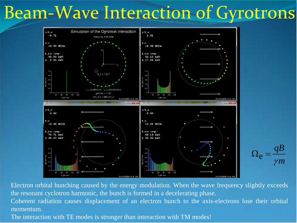
Electron orbital bunching caused by the energy modulation. When the wave frequency slightly exceeds the resonant cyclotron harmonic, the bunch is formed in a decelerating phase. Coherent radiation causes displacement of an electron bunch to the axis-electrons lose their orbital momentum. The interaction with TE modes is stronger than interaction with TM modes!
eqBmγ
Ω =

MVED Applications
Communications Electron linear Accelerators Directed Energy Weapon(DEW) Radio Detection and Ranging (Radar) Electronic Warfare Medical Application Industrial and Commercial Applications Scientific Applications Potential Applications

Communications
Satellite Commutations
Microwaves are used extensively in satellite communication for the transmission of signals and information because of their ability to penetrate Earth’s atmosphere with minimum losses, high frequency and short wavelength. The high frequency of microwaves provides a greater bandwidth capability so that more information can be transmitted within the bandwidth. For example, when using an AM radio signal with a carrier frequency of 1000 kHz to transmit audio information contained over a bandwidth of 40 kHz, it will take up 4% of the carrier, while the use of a 10 GHz microwave signal with a 10% bandwidth system can provide a bandwidth of 1 GHz that will allow transfer of more information such as AM and FM radio signals, shortwave radio, broadcast television, telephone calls and computer digital data simultaneously.
A satellite communication system consisting of (a) a space satellite and (b) a ground station for transmitting or receiving signals

The DSN 220 ft. antenna, a Varian 500 kW CW klystron, and its housing at the antenna center
Interplanetary communications
•The NASA Deep Space Network is an international network of antennas that supports interplanetary spacecraft missions and radio and radar astronomy observations for the exploration of the solar system and the universe. The network also supports selected Earth-orbiting missions. The DSN currently consists of three deep-space communications facilities placed approximately 120 degrees apart around the world. This strategic placement permits constant observation of spacecraft as the Earth rotates, and helps to make the DSN the largest and most sensitive scientific telecommunications system in the world.

High Bandwidth Communications High Carrier Frequencies along with 10% Bandwidth
Result in Very High Data Rates (>10 GB/s) Comparison in Ku Band • Same Antenna Size: ~10x Higher Shannon Capacity • Same Shannon Capacity: ~ 100x Smaller Antenna Area

High Bandwidth Communications 100 GB/S RF BACKBONE Program of USA
Backbone communications networks rely on high-capacity links to interconnect the major nodes of the network and to handle the aggregated voice, video, internet, and enterprise data flows. Telecommunication infrastructure relies heavily on single-mode optical fiber as the data backbone. However, military can't rely on a fixed infrastructure for deployed operations and instead needs a means of projecting fiber-optic-equivalent capacity anywhere within the area of responsibility. A logical approach is to use free-space optical (FSO) links to project the capacity. However, FSO links can't propagate through clouds, which are present 40% of the time in some regions and lead to unacceptable network availability. The goal of the 100 Gb/s RF Backbone (100G) program is to design, build and test an airborne-based communications link with fiber-optic-equivalent capacity and long reach that can propagate through clouds and provide high availability. 100G will combine high-order modulation and spatial multiplexing to achieve spectral efficiencies at or above 20 bits-per-second per Hz. The system will provide 100 Gb/s capacity at ranges of 200 km for air-to-air links and 100 km for air-to-ground links from a high-altitude (e.g. 60,000 ft.) aerial platform. Additionally, the system will provide an all-weather (cloud, rain, and fog) capability while maintaining tactically-relevant throughput and link ranges. Size, weight, and power will be limited by the host platforms, which will primarily be high-altitude, long-endurance aerial platforms.

Project Loon
Many of us think of the Internet as a global community. But two-thirds of the world’s population does not yet have Internet access. Project Loon is a network of balloons traveling on the edge of space, designed to connect people in rural and remote areas, help fill coverage gaps, and bring people back online after disasters. Project Loon balloons float in the stratosphere, twice as high as airplanes and the weather. In the stratosphere, there are many layers of wind, and each layer of wind varies in direction and speed. Loon balloons go where they’re needed by rising or descending into a layer of wind blowing in the desired direction of travel. People can connect to the balloon network using a special Internet antenna attached to their building. The signal bounces from this antenna up to the balloon network, and then down to the global Internet on Earth

Communications needs of MVED: Tubes covering all commercial frequency ranges (from several
hundreds MHz to several hundreds GHz) Large available output power range (several tens of W–to several
kWs) Compatibility to all types of payloads (thermal and mechanical
requirements) High reliability for the required mission Flexibility to meet the evolving needs of the customer
application Long Life Cycle High efficiency Antiradiation effect CW Operation Tubes: TWT, Klystron ,EIK, Gyrotwt, Gyroklystron, SBTWT

Electron linear Accelerators Electron Accelerators in Cancer Therapy Security Non-Destructive Testing and Inspection Prospecting for gold

Electron Accelerators for the source of x-rays
A major contributor to the accelerator business is the use of linacs for radiation therapy of cancer. As people live longer cancer rates are rising. Approximately 11,000 medical accelerators are currently in operation worldwide, the majority in the developed nations. Their average cost is around $3M each, not including the cost of the radiation shielded room enclosing the system. Of interest to the tube community, each accelerator requires a multi-megawatt pulsed microwave tube to drive it. Typically either klystrons or magnetrons are used, the vast majority operating close to 3GHz, but X-band systems are also produced. A 15MV beam of X-rays generated by an electron linac can penetrate through 30 inches of steel. This enables the simple airport X-ray systems used for baggage scanning to be scaled up to handle 40 foot cargo containers.
Schematic of a typical medical linear accelerator used for cancer treatment

Prospecting for gold A slightly unusual application of electronic accelerators is rapid
mineralogical analysis of rock samples when prospecting for gold. Gold ore is typically found in very thin layers buried under a large
overburden of non-gold bearing rock. Mining companies drill multiple boreholes to evaluate the gold prospects. They extract drill cores that provide a cross-section through the rock with depth.
A rapid, sensitive, non-contact method of measuring the gold content is needed.
Electron accelerators can be used to irradiate the drill core transversely with energetic X-rays and excite characteristic X-ray emission lines from the gold.
It is possible quickly measure the gold content in the drill core down to a few ppm on site, without resorting to traditional wet chemical techniques .

Electron linear Accelerators Needs for MVEDs
Very High Peak Power: several hundreds of kWs–to several hundreds of MWs
Middle Frequency :several GHz to 30 GHz Low working Duty, low bandwith and low repetition
Tubes: Klystron ,Magnetron, Gyroklystron, SBK

Directed Energy Weapon(DEW)

Directed Energy Weapon(DEW)
To generate millimeter wave energy that reaches tactically significant ranges (on the order of hundreds of meters), a substantial amount of electrical energy is needed by the millimeter wave source. A Humvee with a hybrid electric power plant, using a combination of lithium ion batteries and a diesel generator, was chosen as the optimum method for generating and storing the required electric energy in the constrained space of the Humvee. Gyrotron, which is commonly used in high-power radio frequency applications, was selected. The source developed for ADS achieved record breaking levels of power conversion efficiency for this type of device—in excess of 50 percent—and output power levels of approximately 100 kilowatts. It was necessary to produce very high magnetic fields around the gyrotron, which was achieved with a liquid helium cryo compressor.

Directed Energy Weapon(DEW)
10 kW CW WSBK, 1-4 tubes for 10-40kW CW

Radio Detection and Ranging (Radar)
Search and rescue Emergency beacon to aid in locating and rescuing aircraft, vessels and people in distress.
Air traffic control Provide location, speed, identification and guidance of planes in and out of an airport. Air and missile defense Surveillance and identification of enemy aircraft or missiles and deployment of
weapons against them. Missile guidance Control the flight of a ballistic missile to the target. Land warfare Battlefield surveillance, detection and location of mortar and artillery and mine detection. Navigation and tracking Provide information on directions and locations and tracking of people, vehicles,
ships and aircraft. Remote sensing and Provide terrain and geographical maps of the ground, information mapping on fire
outbreak, pollution, ice mapping and the ozone layer. Weather Monitor and provide information on precipitation, wind speed and cloud formation. Space exploration Study of distant stars and planets.
Radar is a method of determining the presence, location, velocity and other characteristics of a target through the use of equipment that operates at microwave frequencies. A microwave signal is transmitted by radar and is reflected from the target/object back to the radar. The reflected signal is compared with the transmitted signal to determine the velocity, range, azimuth, elevation and shape of the target/object. Originally developed for military applications, the Global Positioning System (GPS) is a well-known example of the use of radar in navigation. Here are the lists the different applications of radar and its function, bellow illustrate some of the applications of radar.
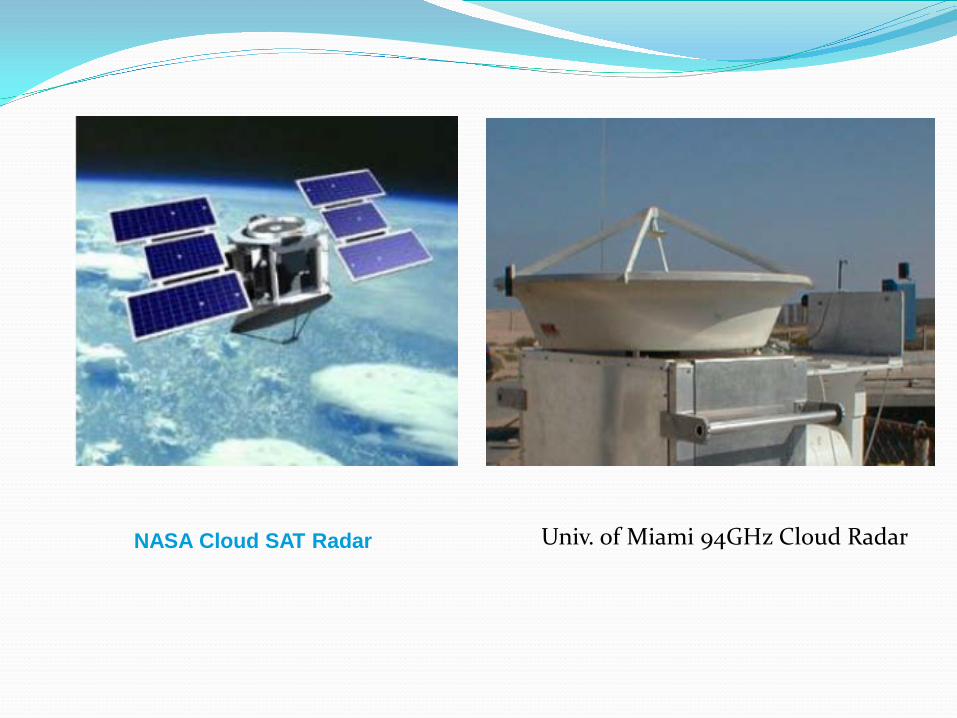
NASA Cloud SAT Radar Univ. of Miami 94GHz Cloud Radar

Klystron 9 Weather Radar
Klystron 9 combines, for the first time in history, a dual Polari metric radar with a 1.25 MW Klystron. The dual-polari metric radar allows the station to offer its viewers increased weather detail, higher resolution imaging and enhanced accuracy. Unlike conventional radar systems dual-polarimetric radar transmits in horizontal and vertical orientations simultaneously, enabling meteorologists to see twice the data. It provides more accurate information about the size, shape, orientation and state of hydrological data, allowing more precise forecasting.

W-band radar (WARLOC), 100 kW peak,10 kW average
There is current interest within the navy to develop high average power gyroklystron amplifiers to generate millimeter wave ectromagnetic radiation for enhanced performance W-Band radar applications. These applications include high resolution imaging, precision tracking, and cloud physics studies.


The Haystack antenna is used to conduct single-dish radio astronomy in the 22-25 GHz, 35-50 GHz and 85-115 GHz frequency bands, and for Very Long Baseline Interferometry experiments. It utilizes the 37 m Haystack antenna to generate radar images of satellites orbiting the Earth. These images are used by the United States Strategic Command to assess satellite structure, mission, and status. The radar is also used to collect data on orbiting space debris. Orbiting debris could be a threat to the International Space Station, the Space Shuttle, and other satellites. The Haystack Radar has been the major contributor to understanding the space debris environment in the 1-10 cm size regime. It currently operates in the 9.5 GHz to 10.5 GHz frequency band. As part of the upgrade, a millimeter-wave radar that operates in the 92 GHz to 100 GHz frequency band will be added to the system. The new radar will use an innovative transmitter design (GyroTWT and Gyroklystron) to achieve image resolution that is about 10 times better than what is currently available.
Haystack ultra-wideband Satellite Imaging Radar(HUSIR)

SBX (Sea Based X-Band) Radar, for Ballistic Missile Defense
Supply Traveling Wave Tubes for U.S. Air Force Radar Systems
The PARCS radar is the largest phased-array radar system in the world. The Air Force assigned the radar the primary mission of warning/attack assessment of Submarine Launched Ballistic Missile (SLBM) and Intercontinental Ballistic Missile (ICBM) attack. The radar is so precise, it can identify objects the size of a basketball at a range of 2,000 miles. Its secondary mission is to track space debris that could interfere with shuttle missions as well as satellites. The SBX provides 120-degree radar coverage of a 2,000-mile corridor that spans the eastern Russian peninsula and northern Pacific Ocean. Its digital data and voice communication systems interface with the National Air Intelligence Center and the North American Aerospace Defense Command. The system also provides early warning and attack assessment for missiles.

SAR (Synthetic Aperture Radar) Single Antenna, Active System
Beam is broad in vertical direction (Range)
Range is determined by measuring echoes
Gathers Signal at Different Position & Times
• Signals are Function of Location of Antenna
• Simulates a Long 1D Phased Array thru Signal Processing
Ku Band (16 GHz) 1 M Resolution
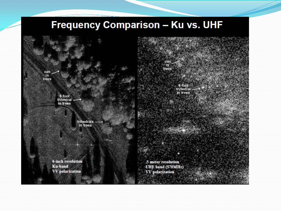

• Active System –Day and Night Imaging • Adverse Weather • High Quality Image
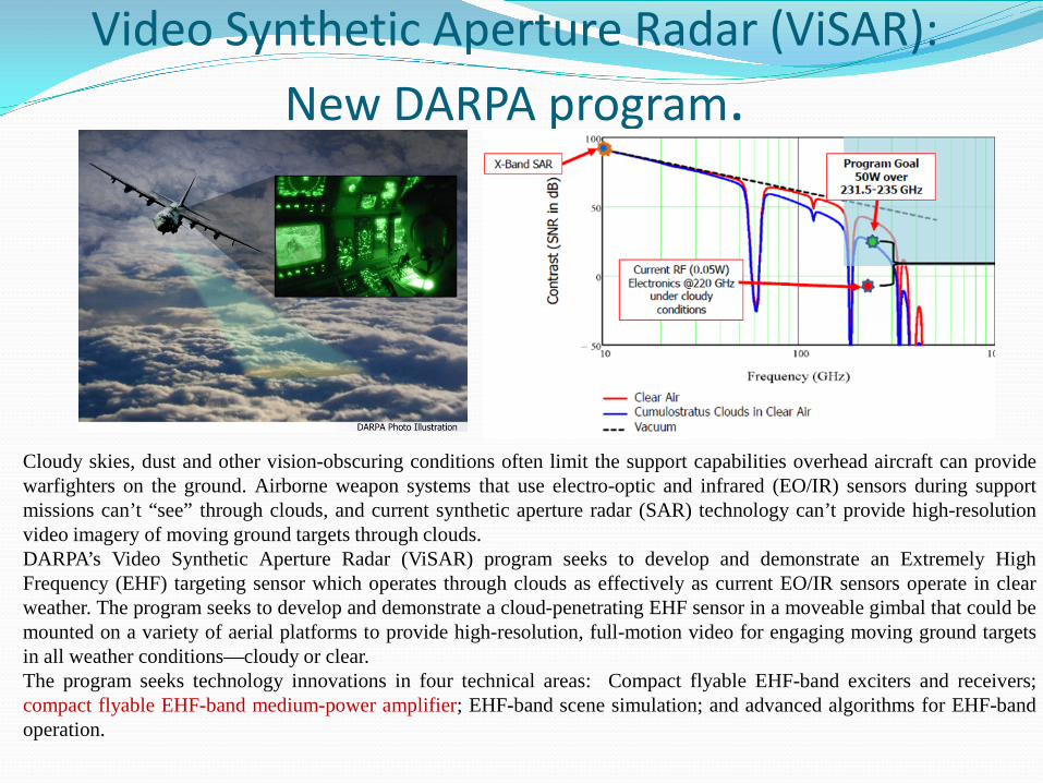
Video Synthetic Aperture Radar (ViSAR): New DARPA program.
Cloudy skies, dust and other vision-obscuring conditions often limit the support capabilities overhead aircraft can provide warfighters on the ground. Airborne weapon systems that use electro-optic and infrared (EO/IR) sensors during support missions can’t “see” through clouds, and current synthetic aperture radar (SAR) technology can’t provide high-resolution video imagery of moving ground targets through clouds. DARPA’s Video Synthetic Aperture Radar (ViSAR) program seeks to develop and demonstrate an Extremely High Frequency (EHF) targeting sensor which operates through clouds as effectively as current EO/IR sensors operate in clear weather. The program seeks to develop and demonstrate a cloud-penetrating EHF sensor in a moveable gimbal that could be mounted on a variety of aerial platforms to provide high-resolution, full-motion video for engaging moving ground targets in all weather conditions—cloudy or clear. The program seeks technology innovations in four technical areas: Compact flyable EHF-band exciters and receivers; compact flyable EHF-band medium-power amplifier; EHF-band scene simulation; and advanced algorithms for EHF-band operation.

Radar Needs for MVEDs: High peak Power: several tens of kWs to several MWs High Average Power: several tens of kWs High Frequency :few GHz to few hundreds of GHz Tubes: TWT , Klystron, Magnetron, GyroTWT and Gyroklystron

Electronic Warfare Electronic attack involves the use of electromagnetic energy to
reduce the effectiveness of the enemy’s radar. Microwave bombs create a short and intense electromagnetic
pulse (EMP) which generates a transient surge of thousands of volts capable of disabling all electronic devices within range.
HPM sources have been under investigation for several years as potential weapons for a variety of combat, sabotage, and terrorist applications. Due to the gigahertz-band frequencies (4 to 20 GHz) involved, HPM has the capability to penetrate not only radio front-ends, but also the most minute shielding penetrations throughout the equipment. At sufficiently high levels, as discussed, the potential exists for significant damage to devices and circuits.
Electromagnetic Pulse (EMP) and High Powered Microwave (HMP) Weapons offer a significant capability against electronic equipment susceptible to damage by transient power surges. This weapon generates a very short, intense energy pulse producing a transient surge of thousands of volts that kills semiconductor devices. The conventional EMP and HMP weapons can disable non-shielded electronic devices including practically any modern electronic device within the effective range of the weapon.
The effectiveness of an EMP device is determined by the power generated and the characteristic of the pulse. The shorter pulse wave forms, such as microwaves, are far more effective against electronic equipment and more difficult to harden against.
High-power microwave (HPM) / E-Bomb

A vircator (VIRtual CAthode oscillaTOR) is a microwave generator that is capable of generating brief pulses of tunable, narrow band microwaves at very high power levels. Power levels on the order of 1010 to 1012 watts are possible. A typical vircator is built inside an evacuated resonant cavity or waveguide. An electrode, a cold cathode, at one end injects an intense electron beam, such as from a Marx generator or a flux compression generator, optionally with a suitable pulse forming network. The pulse has magnitude in the range of hundred or more kilovolts and duration of about 50-150 nanoseconds. The electrons are attracted to a thin anode that is connected to the grounded waveguide body. The unit is surrounded by a magnet. The frequencies are usually in the ballpark of 0.5-1.5, 2-6, 3, or 5-18 GHz. Other frequencies are also possible. Lower frequencies are usable for jamming communications, higher frequencies can be harnessed for their destructive effects on electronics. The massive short pulse of high voltage causes the cathode to emit an intense burst of electrons by the field electron emission mechanism. The electrons are attracted to the anode. A large proportion of the electrons passes through the anode and forms a cloud behind it, forming the virtual cathode. However, the electrons are still attracted by the anode (and repulsed by each other), so they change direction and fly back towards the anode, only to pass through again and be repulsed by the cathode and attracted towards the anode. The rapidly accelerating and decelerating electrons, as they oscillate back and forth between the real and virtual cathode through the mesh anode at microwave frequencies, then produce electromagnetic radiation.

Electronic Warfare Needs for MVEDs: Extremely High Peak Power: several GWs to few tens
of GWs Low working duty:several microseconds bandwith
and low repetition Tubes: Vicator (VIRtual CAthode oscillaTOR) , FEL, Relativistic Magnetron, Relativistic TWT and Relativistic BWO, MILO(Magnetically insulated oscillator)
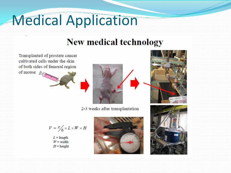
Medical Application

The tube fit for this application will be Gyrotron, SBTWT and SBBWO

Industrial and Commercial Applications Semiconductor processing Microwave discharge lamps. Security sector. X-ray imaging Material Processing
Magnetron and Gyrotron

Scientific Applications • Linear accelerators use microwave power generated by a
klystron for high energy physics research. • Accelerate and enhance chemical synthesis and reactions. • Microwave absorption spectroscopy • Dynamic Nuclear Polarization, nuclear magnetic
resonance spectroscopy and electron spin resonance spectroscopy.
• The heating of plasma to extremely high temperatures for nuclear fusion research.

High Energy Physics Accelerators
Stanford Linear Accelerator Center
Linear accelerators use microwave power generated by a klystron for high energy physics research. At the Stanford Linear Accelerator Center, microwaves provide energy to accelerate the electrons along the two-mile accelerator structure with one klystron every forty feet.

Microwaves are used in the heating of plasma to extremely high temperatures for nuclear fusion research. Microwave-producing gyrotrons are used worldwide in almost every controlled fusion installation to heat plasma to the immense energies required for nuclear fusion. Nuclear fusion possesses many advantages such as the release of more energy than nuclear fission, easy availability of fuel and environmental friendliness with no hazardous waste or by-products produced. ITER is an international project involving The People’s Republic of China, the European Union and Switzerland, India, Japan, the Republic of Korea, the Russian Federation and the United States of America in the development of a nuclear fusion reactor capable of operating at over 100 million degrees Celsius and producing 500MW of fusion power at France at a cost of over $3500 million over 20 years.
The schematic of the ITER nuclear fusion reactor


Potential Applications
Many potential applications of microwaves are envisioned due to their unique properties. One possible future use of microwaves that has generated much interest is the use of microwaves for power transmission and solar-powered satellites. It was demonstrated the JPL Goldstone facility in the Mojave desert, USA that 30 kW of microwave power can be transmitted over 1.6 km and converted to dc power with an efficiency of 84 %. An artist’s impression of future microwave power transmission using a solar-powered satellite is illustrated in this Figure. Active research on microwave power transmission has also been carried out in Japan, Russia, France, Canada and Germany.
Artist’s impression of future microwave power transmission using a solar-powered satellite

Potential Applications
Weather Control It is also envisioned that microwaves can be used to control the intensity and alter the path of hurricanes by heating the air around a hurricane using an array of solar-powered satellites. As we can see from these two picture, a large array of high power antenna create the aurora.

Potential Applications
Also, it has been proposed that microwaves could provide energy for future space transportation. The Microwave Light craft concept developed by NASA is powered by microwaves beamed from an orbiting solar-powered satellite to the light craft. The energy received breaks air molecules into a plasma and a magnetohydrodynamic fanjet provides the lifting force.
The Microwave Light craft concept

Then,Development and Future of MVEDS
The Progression of device power density for major device types

Photograph of a common planar triode
External cavity reflex klystron
Split Anode Magnetron

Traveling Wave Tube (TWT)

1984
2012
1 mW 0.9 THz
52 mW 0.656 THz Backward wave oscillator
BWO State of the Art

Ka band Multi Stage Depressed Collector (MSDC) EIK with a efficiency in excess of 50%
Ka- and W-band EIKs for Space-borne Applications


Future of MVED
Extremely high power at low frequency(several GHz several MW to GW)
High frequency(THz) development High power from 0.1THz to 1 THz Small size device Tiny tube

Vacuum Electronics Technology has the ability to handle high power in a relatively small volume, hence micro-scale Vacuum Electron Devices (μVED) generated substantial interest for a coherent radiation MMwave-THz source
Pf2 is a measure of radiation power density of an amplifier Pf2(∆f/f) measures the ability of the device to transmit information Figure shows high frequency devices in terms of Pavf2(∆f/f) as figure of merit

Collector
RF Output Window
Input Coupler With Tapered Vane Transitions
PPM Stack
Demountable Tube Assembly:
Gun, Windows, and Collector are demountable via UC Davis Wire-
Seal approach
220 GHz SBTWT Anis(Anissullah Baig)Tube
12.5 : 1 Aspect Ratio Sheet Beam Gun (Measured Cathode Emission Current Loading = 56 A/cm2)
49 mm
Input Coupler
Output Coupler
Nano-CNC Machined Circuit
Tapered Output Coupler

The Future Tiny SBBWO 0f 350GHz in UCDavis

Design concept, circuit layout & simple analysis of a 1200 GHz nanoklystron

MVED Research in UESTC
Millimeter wave TWT High Power Millimeter wave
Gyrotrons The MVED design 3D software

MVED Research in UESTC
A coupler Cavity TWT and Helix Circuit TWT

MVED Research in UESTC
95GHz Gyrotron
200GHz Gyrotron
420GHz Gyrotron

MVED Research in UESTC
A Ka band GyroTWT
A Ku band GyroTWT

MVED Research in UESTC
3D Softwares Developed in UESTC

MVED Research in UESTC
3D PIC Softwares Developed in UESTC

MVED Research in UESTC

Thank You For you Attention!