Microwave and Millimeter e Wave NDT&E - Missouri S&T Applied
117
C o p y ing , r e p r o d u c t ion a n d r e t r a n s m is s ion o f a n y p o r t ion o f t h is p r e s e n t a t ion is N OT p e r m it t e d w it h o u t e x p r e s s e d w r it t e n c o n s e n t o f t h e d ire c t o r . MicrowaveandMillimeter WaveNDT& E Prin ciples,Methodsand App lications No te: I f vi ew ingt his pr es entation inS afari, righ t clic k and clic k on Open withP re vi ew .
Transcript of Microwave and Millimeter e Wave NDT&E - Missouri S&T Applied

Copyin
g,
repro
ductio
n a
nd r
etr
ansm
issio
n o
f any p
ort
ion o
f th
is p
resenta
tio
n is N
OT
perm
itte
d w
ithout
expre
ssed w
ritt
en c
onse
nt
of th
e d
irecto
r.
Microwave and Millimeter Wave NDT&E
Principles, Methods and Applications
Note: If viewing this presentation in Safari, right click
and click on Open with Preview.

Copyin
g,
repro
ductio
n a
nd r
etr
ansm
issio
n o
f any p
ort
ion o
f th
is p
resenta
tio
n is N
OT
perm
itte
d w
ithout
expre
ssed w
ritt
en c
onse
nt
of th
e d
irecto
r.
This presentation is based on the results of research and activities in the areas of microwave and millimeter wave NDT&E performed at the:
Applied Microwave Nondestructive Testing Lab. ( amntl)Electrical and Computer Engineering Department
Missouri University of Science and Technology (S&T)
Rolla, MO 65409
For more information contact professor R. Zoughi (Director)
(573) 341-4656 (office)
(573) 341-4728 (lab.)

Copyin
g,
repro
ductio
n a
nd r
etr
ansm
issio
n o
f any p
ort
ion o
f th
is p
resenta
tio
n is N
OT
perm
itte
d w
ithout
expre
ssed w
ritt
en c
onse
nt
of th
e d
irecto
r.
OutlineÉBackground.
ÉMaterial characterization.
ÉMulti - layer composite inspection.
ÉCorrosion and corrosion precursor pitting detection under paint.
ÉSurface crack detection and evaluation.
ÉReal- aperture, synthetic aperture and holographical imaging for inspection of several different types of composites.
ÉFuture.

Copyin
g,
repro
ductio
n a
nd r
etr
ansm
issio
n o
f any p
ort
ion o
f th
is p
resenta
tio
n is N
OT
perm
itte
d w
ithout
expre
ssed w
ritt
en c
onse
nt
of th
e d
irecto
r.
BACKGROUND

Copyin
g,
repro
ductio
n a
nd r
etr
ansm
issio
n o
f any p
ort
ion o
f th
is p
resenta
tio
n is N
OT
perm
itte
d w
ithout
expre
ssed w
ritt
en c
onse
nt
of th
e d
irecto
r.
Frequency Spectra300 MHz
1000 mm
300 GHz
1 mm
30 GHz
10 mm
m- Waves mm- Waves
Q- Band33- 50.5
V- Band50- 75
W- Band75- 110
Ka- Band26.5 - 40
D- Band110 - 170
X- Band8.2 - 12.4
Ku- Band12- 18
K- Band18- 26.5
Waveguide Bands
G- Band140 - 220

Copyin
g,
repro
ductio
n a
nd r
etr
ansm
issio
n o
f any p
ort
ion o
f th
is p
resenta
tio
n is N
OT
perm
itte
d w
ithout
expre
ssed w
ritt
en c
onse
nt
of th
e d
irecto
r.
Waveguides & Horn Antenna Examples
K- Band10.7 x 4.3
Ka- Band7.11 x 3.56
V- Band3.8 x 1.9
W- Band2.54 x 1.27 (mm x mm)
10 mm

Copyin
g,
repro
ductio
n a
nd r
etr
ansm
issio
n o
f any p
ort
ion o
f th
is p
resenta
tio
n is N
OT
perm
itte
d w
ithout
expre
ssed w
ritt
en c
onse
nt
of th
e d
irecto
r.
BackgroundÉThese signals penetrate into dielectric
materials, as a function of their dielectric properties and frequency.
ÉSensitive to dielectric property variation:
Vabrupt (boundaries)
Vlocal (inclusions)
Vgradual (gradient in material change).
ÉPolarization, frequency, measurement parameter (near - field vs. far - field) & probe type diversity - degrees of freedom.
ÉSensitive to conductor surface properties ðcracks, impact damage, etc.

Copyin
g,
repro
ductio
n a
nd r
etr
ansm
issio
n o
f any p
ort
ion o
f th
is p
resenta
tio
n is N
OT
perm
itte
d w
ithout
expre
ssed w
ritt
en c
onse
nt
of th
e d
irecto
r.
Advantageous FeaturesÉ Coherence properties ðmagnitude & phase.
É Large available bandwidth.
É Life - cycle inspection possibilities.
É Electromagnetic modeling (analytical, numerical and empirical).
É On- line and real - time inspection.
É Operation in industrial environments.
É Little to no need for operator expertise.
É Relatively inexpensive.
É Applications to where òstandardó NDT&E techniques have limited applicability.

Copyin
g,
repro
ductio
n a
nd r
etr
ansm
issio
n o
f any p
ort
ion o
f th
is p
resenta
tio
n is N
OT
perm
itte
d w
ithout
expre
ssed w
ritt
en c
onse
nt
of th
e d
irecto
r.
Advantageous FeaturesÉMeasurement systems are:
Vnon- contact
Vone- sided
Vmono- static
Vcompact and small
Vlow power
Vin- field & operator friendly
Vadaptable to existing scanning platforms
Vrobust & repeatable

Copyin
g,
repro
ductio
n a
nd r
etr
ansm
issio
n o
f any p
ort
ion o
f th
is p
resenta
tio
n is N
OT
perm
itte
d w
ithout
expre
ssed w
ritt
en c
onse
nt
of th
e d
irecto
r.
What Can Be Done?ÉMaterial characterization - evaluation of
dielectric properties of materials.
ÉEvaluation of moisture in composites.
ÉCure- state monitoring.
ÉRelating microwave properties to physical & mechanical properties of materials.
ÉComprehensive inspection of thick composite materials and structures.
ÉDielectric coating evaluation.
ÉThickness variation/quality control.
ÉDetection and evaluation of disbond, delamination, void & porosity.

Copyin
g,
repro
ductio
n a
nd r
etr
ansm
issio
n o
f any p
ort
ion o
f th
is p
resenta
tio
n is N
OT
perm
itte
d w
ithout
expre
ssed w
ritt
en c
onse
nt
of th
e d
irecto
r.
What Can Be Done?É Detection of defect/inhomogeneity in
dielectric composites.
É Evaluation of defect size and properties.
É Production of high - resolution defect images.
É Detection and evaluation of properties of surface cracks, anomalies & perturbations (impact damage) in metals and graphite composites.
É Conductor & dielectric sheet surface profiling.
É Detection and evaluation of corrosion and precursor pitting under coatings.

Copyin
g,
repro
ductio
n a
nd r
etr
ansm
issio
n o
f any p
ort
ion o
f th
is p
resenta
tio
n is N
OT
perm
itte
d w
ithout
expre
ssed w
ritt
en c
onse
nt
of th
e d
irecto
r.
Stratified Composites - Examples
. . .
Thermal Barrier CoatingCorrosion
Under Paint
Probe

Copyin
g,
repro
ductio
n a
nd r
etr
ansm
issio
n o
f any p
ort
ion o
f th
is p
resenta
tio
n is N
OT
perm
itte
d w
ithout
expre
ssed w
ritt
en c
onse
nt
of th
e d
irecto
r.
Life -Cycle Inspection ðRubber Products
Carbon Black, EPDMZinc Oxide, OilCuratives, etc.
BeltHose
Process
MixerUncured Cured
HeatSheet
MultipleSheets
Adhered
ProcessProcess
Indicates where microwaveevaluation can be implemented.
Copyin
g,
repro
ductio
n a
nd r
etr
ansm
issio
n o
f any p
ort
ion o
f th
is p
resenta
tio
n is N
OT
perm
itte
d w
ithout
expre
ssed w
ritt
en c
onse
nt
of th
e d
irecto
r.
MATERIAL CHARACTERIZATION

Copyin
g,
repro
ductio
n a
nd r
etr
ansm
issio
n o
f any p
ort
ion o
f th
is p
resenta
tio
n is N
OT
perm
itte
d w
ithout
expre
ssed w
ritt
en c
onse
nt
of th
e d
irecto
r.
Material CharacterizationÉ An insulating material becomes polarized in
the presence of an electric field.
É Although the process occurs at atomic and molecular level, polarization vector is used to describe the process macroscopically through dielectric constant or properties.
É The ability of a material to store energy (microwave) is denoted by its (relative to free - space) permittivity, eõr .
É The ability of a material to absorb energy (microwave) is denoted by its (relative to free - space) loss factor, eór .
É These two parameters are the basis for material characterization.

Copyin
g,
repro
ductio
n a
nd r
etr
ansm
issio
n o
f any p
ort
ion o
f th
is p
resenta
tio
n is N
OT
perm
itte
d w
ithout
expre
ssed w
ritt
en c
onse
nt
of th
e d
irecto
r.
Material Characterization
p =qd CÖm( )
P = limDv0
1
Dvp
i=1
nä
è
ê é é
ø
ú ù ù
C / m2( )
e=eo 1+ce( ) F / m( )
e=e'-je"=e'-jse
w
å
ç æ õ
÷ ö
er =e
eo
=e'r -je"r
tand=e"
e'

Copyin
g,
repro
ductio
n a
nd r
etr
ansm
issio
n o
f any p
ort
ion o
f th
is p
resenta
tio
n is N
OT
perm
itte
d w
ithout
expre
ssed w
ritt
en c
onse
nt
of th
e d
irecto
r.
Material Characterization ÉDetermine a mixture constituent makeup
via dielectric mixing models.
ÉControl mixture properties.
ÉCorrelate measured dielectric properties to chemical, physical & mechanical properties.
ÉCure- state monitoring.
ÉDetermine porosity level in TBC, ceramics, refractory, plastics, etc.
ÉDetermine moisture content in materials.

Copyin
g,
repro
ductio
n a
nd r
etr
ansm
issio
n o
f any p
ort
ion o
f th
is p
resenta
tio
n is N
OT
perm
itte
d w
ithout
expre
ssed w
ritt
en c
onse
nt
of th
e d
irecto
r.
Material CharacterizationÉMeasured dielectric properties, as a
function of frequency, yields valuable information about material properties.
ÉFor mixtures (i.e., porosity in TBC) various dielectric mixing models may be used to extract a particular information such as porosity level.

Copyin
g,
repro
ductio
n a
nd r
etr
ansm
issio
n o
f any p
ort
ion o
f th
is p
resenta
tio
n is N
OT
perm
itte
d w
ithout
expre
ssed w
ritt
en c
onse
nt
of th
e d
irecto
r.
Material CharacterizationÉMeasurement considerations:
VMaterial type, i.e. liquid, solid, gas, etc.
VOn- line or off - line
VRequired measurement accuracy
VLoss tangent of the material
VNondestructive vs. destructive
VNon- contact vs. in - contact
VMaterial geometry
VParticular information sought

Copyin
g,
repro
ductio
n a
nd r
etr
ansm
issio
n o
f any p
ort
ion o
f th
is p
resenta
tio
n is N
OT
perm
itte
d w
ithout
expre
ssed w
ritt
en c
onse
nt
of th
e d
irecto
r.
Measurement MethodsÉ Loaded transmission line:
VCompletely - filled waveguides.
VCompletely - filled coaxial lines.
VPartially - filled waveguides.
VOpen- ended waveguides and coaxial lines into either finite - thickness or infinite half - space.
ÉCavity resonators.
ÉMicrostrip patches.
ÉFree - space transmission and/or reflection methods.

Copyin
g,
repro
ductio
n a
nd r
etr
ansm
issio
n o
f any p
ort
ion o
f th
is p
resenta
tio
n is N
OT
perm
itte
d w
ithout
expre
ssed w
ritt
en c
onse
nt
of th
e d
irecto
r.
Porosity in PolymerFrequency (GHz) 0% 48.9% 58.7% 68.5%
8.2 2.80 1.87 1.69 1.48
10 2.87 1.84 1.63 1.46
12 2.83 1.88 1.70 1.47
14 2.87 1.83 1.70 1.50
16 2.84 1.82 1.68 1.47
18 2.84 1.84 1.67 1.47
Frequency (GHz) 0% 48.9% 58.7% 68.5%
8.2 0.086 0.032 0.020 0.013
10 0.086 0.034 0.023 0.015
12 0.082 0.033 0.022 0.014
14 0.083 0.033 0.027 0.022
16 0.077 0.026 0.021 0.019
18 0.068 0.027 0.025 0.014
ñReproduced with permission, Materials Evaluation, vol. 53, no. 3, 1995, ÉAmerican Society for Nondestructive Testing.ò
Relative Permittivity
Relative Loss Factor

Copyin
g,
repro
ductio
n a
nd r
etr
ansm
issio
n o
f any p
ort
ion o
f th
is p
resenta
tio
n is N
OT
perm
itte
d w
ithout
expre
ssed w
ritt
en c
onse
nt
of th
e d
irecto
r.
Salt Water Permeation in Mortar
Open-Ended Rectangular Waveguide Probe
Specimen Under Test
Successive Chloride Penetration
Approximate Depth to which Microwave Signal Irradiates the Specimen
er1 er2
erNOpen-Ended Rectangular
Waveguide Probe
t1 2
t
Infinite Half-Space
0
0.5
1
1.5
2
2.5
3
3.5
0 20 40 60 80 100
Day 2Day 3Day 6Day 9Day 13Day 17Day 22Day 28Day 33
Distance from Surface (mm)
Wate
r C
on
ten
t D
istr
ibution
(g
m/m
m)
0
0.5
1
1.5
2
2.5
3
3.5
0 20 40 60 80 100
Day 2Day 3Day 5Day 8Day 12Day 17Day 23Day 29Day 35
Distance from Surface (mm)
Wate
r C
on
ten
t D
istr
ibution
(g
m/m
m)
ñÉ 2004 IEEE. Reprinted, with permission, from IEEE Transactions on Instrumentation and Measurement, vol. 53, no. 2, pp. 406-415, April, 2004.ò

Copyin
g,
repro
ductio
n a
nd r
etr
ansm
issio
n o
f any p
ort
ion o
f th
is p
resenta
tio
n is N
OT
perm
itte
d w
ithout
expre
ssed w
ritt
en c
onse
nt
of th
e d
irecto
r.
Salt Water Permeation in Mortar
0
0.01
0.02
0.03
0.04
0.05
0 5 10 15 20 25 30 35 40
Day 3
Day 5
Day 8
Day 12
Day 15
Day 20
Day 28
Day 33
Distance from Surface (mm)
Cry
sta
l S
alt
Recalculation of Cyclical Crystal Salt Deposition in Mortar Blocks

Copyin
g,
repro
ductio
n a
nd r
etr
ansm
issio
n o
f any p
ort
ion o
f th
is p
resenta
tio
n is N
OT
perm
itte
d w
ithout
expre
ssed w
ritt
en c
onse
nt
of th
e d
irecto
r. GENERAL MULTI -
LAYERCOMPOSITES

Copyin
g,
repro
ductio
n a
nd r
etr
ansm
issio
n o
f any p
ort
ion o
f th
is p
resenta
tio
n is N
OT
perm
itte
d w
ithout
expre
ssed w
ritt
en c
onse
nt
of th
e d
irecto
r.
General Multi -Layer Structure
Open -Ended
Waveguide
Stratified Composite
Conductor
or
Infinite Half -
Space
Standoff
Distance

Copyin
g,
repro
ductio
n a
nd r
etr
ansm
issio
n o
f any p
ort
ion o
f th
is p
resenta
tio
n is N
OT
perm
itte
d w
ithout
expre
ssed w
ritt
en c
onse
nt
of th
e d
irecto
r.
General Multi -Layer Structure
E x ,y , 0( )=Vi oe o ( x, y )+ Vr n
n =0
¤
ä e n ( x , y)
H x, y, 0( )=YoVi oh o ( x ,y )- YnVrn
n=0
¤
ä h n( x , y)
Vr n= E x, y, 0( )¶e n ( x, y )dxdy
S
ññ
Y =G + jB =
E x, y, 0( )³W x , y, 0( )[ ]¶) a z dxdy
S
ññ
E x , y, 0( )¶e o( x ,y )dxdyS
ññè
ê é
ø
ú ù
2
W x, y( )=H x , y, 0( )+ Yn
n=0
¤
ä h n( x , y) E h,z, 0( )S
ññ ¶e n (h,z) dhdz
G=Ge jf =1-Y
1+Y

Copyin
g,
repro
ductio
n a
nd r
etr
ansm
issio
n o
f any p
ort
ion o
f th
is p
resenta
tio
n is N
OT
perm
itte
d w
ithout
expre
ssed w
ritt
en c
onse
nt
of th
e d
irecto
r.
Coating Thickness - Contact
Rubber with 12.4 - j2.4
ñReproduced with permission, Materials Evaluation, vol. 51, no. 6, 1993, ÉAmerican Society for Nondestructive Testing.ò

Copyin
g,
repro
ductio
n a
nd r
etr
ansm
issio
n o
f any p
ort
ion o
f th
is p
resenta
tio
n is N
OT
perm
itte
d w
ithout
expre
ssed w
ritt
en c
onse
nt
of th
e d
irecto
r.
Coating Thickness
ñReproduced with permission, Materials Evaluation, vol. 51, no. 6, 1993, ÉAmerican Society for Nondestructive Testing.ò

Copyin
g,
repro
ductio
n a
nd r
etr
ansm
issio
n o
f any p
ort
ion o
f th
is p
resenta
tio
n is N
OT
perm
itte
d w
ithout
expre
ssed w
ritt
en c
onse
nt
of th
e d
irecto
r.
Non -Contact Disbond
7.55 mm -Thick Rubber with 8.4 - j0.9
10 GHz @ 5 mm Standoff
ñÉ 1994 IEEE. Reprinted, with permission, from IEEE Transactions on Microwave Theory and Techniques, vol. 42, no. 3, pp. 389-395, March, 1994.ò

Copyin
g,
repro
ductio
n a
nd r
etr
ansm
issio
n o
f any p
ort
ion o
f th
is p
resenta
tio
n is N
OT
perm
itte
d w
ithout
expre
ssed w
ritt
en c
onse
nt
of th
e d
irecto
r. IMAGING FOR
NDT&E

Copyin
g,
repro
ductio
n a
nd r
etr
ansm
issio
n o
f any p
ort
ion o
f th
is p
resenta
tio
n is N
OT
perm
itte
d w
ithout
expre
ssed w
ritt
en c
onse
nt
of th
e d
irecto
r.
NDT&E Imaging ConstraintsÉYou can simulate and measure changes in
complex reflection and transmission coefficients and deduce much about the characteristics of a structure.
ÉThis is generally time - consuming, off - line and not real - time.
É In many NDT applications it is first and foremost important to know whether something is wrong (i.e., NDT) and then maybe evaluate its properties (i.e., NDE).

Copyin
g,
repro
ductio
n a
nd r
etr
ansm
issio
n o
f any p
ort
ion o
f th
is p
resenta
tio
n is N
OT
perm
itte
d w
ithout
expre
ssed w
ritt
en c
onse
nt
of th
e d
irecto
r.
NDT&E Imaging ConstraintsÉOperators and technicians need quick
qualitative tools first ðan image of a composite showing an area of potential damage.
É In some applications slight damage may not be tolerated, while in others it may be OK until the next inspection or when a threshold is crossed.
ÉConstraints on imaging capabilities and attributes vary widely in practice ðcorrosion in rebar vs. crack in aircraft fuselage, or disbond in a heat tile!

Copyin
g,
repro
ductio
n a
nd r
etr
ansm
issio
n o
f any p
ort
ion o
f th
is p
resenta
tio
n is N
OT
perm
itte
d w
ithout
expre
ssed w
ritt
en c
onse
nt
of th
e d
irecto
r.
NDT&E Imaging ConstraintsÉOther important constraints include:
VCost
VEase of use
VPortability
VRapid image production
VReal- time image production
VResolution ðspatial and depth
VPersonnel training
VOn- line needs
VLevel of technical comfort ðcommercial scanners, UT, EC, etc.

Copyin
g,
repro
ductio
n a
nd r
etr
ansm
issio
n o
f any p
ort
ion o
f th
is p
resenta
tio
n is N
OT
perm
itte
d w
ithout
expre
ssed w
ritt
en c
onse
nt
of th
e d
irecto
r. NEAR -FIELD
TECHNIQUES
Copyin
g,
repro
ductio
n a
nd r
etr
ansm
issio
n o
f any p
ort
ion o
f th
is p
resenta
tio
n is N
OT
perm
itte
d w
ithout
expre
ssed w
ritt
en c
onse
nt
of th
e d
irecto
r.
Near - Field MethodsÉNear -field imaging using òstanding-waveó or òsingleó reflectometers:
VSimple, inexpensive, small, handheld, portable
VCommonly CW
VHigh spatial resolution ðresolution is probe size dependent
VNo depth resolution
VEasily adaptable to commercially - available scanning platforms
VProvides a great deal of information
VEvaluation of properties not readily possible

Copyin
g,
repro
ductio
n a
nd r
etr
ansm
issio
n o
f any p
ort
ion o
f th
is p
resenta
tio
n is N
OT
perm
itte
d w
ithout
expre
ssed w
ritt
en c
onse
nt
of th
e d
irecto
r.
Near -Field ImagingÉNear - field imaging using coherent imaging
systems or reflectometers:
VComplex in design
VCommonly CW but not always
VHigh spatial resolution ðresolution is probe size dependent and also synthetic aperture focusing is possible
VProvides depth resolution
VRelatively costly and larger
VGenerally not handheld, but yet portable
VNot always easily adaptable to commercially - available scanning platforms
VEvaluation of properties is possible using proper forward and inverse formulations.
Copyin
g,
repro
ductio
n a
nd r
etr
ansm
issio
n o
f any p
ort
ion o
f th
is p
resenta
tio
n is N
OT
perm
itte
d w
ithout
expre
ssed w
ritt
en c
onse
nt
of th
e d
irecto
r.
Near -Field ImagingÉGreat usefulness for a variety of
applications.
ÉParticularly suitable to inspect:
VDielectrics for embedded flaws
VMetals for surface cracks
VStratified composite structures
VCorrosion under paint

Copyin
g,
repro
ductio
n a
nd r
etr
ansm
issio
n o
f any p
ort
ion o
f th
is p
resenta
tio
n is N
OT
perm
itte
d w
ithout
expre
ssed w
ritt
en c
onse
nt
of th
e d
irecto
r.
General Reflectometer Schematic
Divider/Combiner
Comparator/DetectorPhase &/or Mag.
Amp. + DVM
AntennaOscillatorIsolator
ToScanner

Copyin
g,
repro
ductio
n a
nd r
etr
ansm
issio
n o
f any p
ort
ion o
f th
is p
resenta
tio
n is N
OT
perm
itte
d w
ithout
expre
ssed w
ritt
en c
onse
nt
of th
e d
irecto
r.
Glass with Aluminum Inclusion
ñReproduced with permission, Materials Evaluation, vol. 53, no. 8, 1995, ÉAmerican Society for Nondestructive Testing.ò

Copyin
g,
repro
ductio
n a
nd r
etr
ansm
issio
n o
f any p
ort
ion o
f th
is p
resenta
tio
n is N
OT
perm
itte
d w
ithout
expre
ssed w
ritt
en c
onse
nt
of th
e d
irecto
r.
Standoff Distance Influence 1. Contact measurement, max.
signal difference.
2. High level of signal difference, but very sensitive to standoff distance change.
3. Crossover, no distinction between inclusion and no inclusion.
4. Sufficient signal difference while able to tolerate some standoff distance change.
5. Similar to 4, but image gray level flips.
ñReproduced with permission, Materials Evaluation, vol. 53, no. 8, 1995, ÉAmerican Society for Nondestructive Testing.ò
-0.15
-0.1
-0.05
0
0.05
0.1
0.15
0.2
0 5 10 15 20
Vo
ltag
e (V
)
Over
Inclusion
Devoid of
Inclusion
Standoff distance (mm)
1
2
5
3
4

Copyin
g,
repro
ductio
n a
nd r
etr
ansm
issio
n o
f any p
ort
ion o
f th
is p
resenta
tio
n is N
OT
perm
itte
d w
ithout
expre
ssed w
ritt
en c
onse
nt
of th
e d
irecto
r.
Disbond in Thick Composite
44.5 mm
40.1 mm
44.4 mm
Foam
Foam
Foam
3.85 mm
3.85 mm
4.9 mm
3.9 mm
425 mm
310
mm
N-5
Disbond 0.6mm
235 mm18
0 m
m
1.5 mm
2.5 mm3.5 mm
ñReproduced with permission, Materials Evaluation, vol. 60, no. 2, 2002, ÉAmerican Society for Nondestructive Testing.ò
Using Standoff Distance Compensator and at Three Different Standoff
Distances
Disbond Area
Copyin
g,
repro
ductio
n a
nd r
etr
ansm
issio
n o
f any p
ort
ion o
f th
is p
resenta
tio
n is N
OT
perm
itte
d w
ithout
expre
ssed w
ritt
en c
onse
nt
of th
e d
irecto
r.
CORROSIONand
PRECURSOR PITTING

Copyin
g,
repro
ductio
n a
nd r
etr
ansm
issio
n o
f any p
ort
ion o
f th
is p
resenta
tio
n is N
OT
perm
itte
d w
ithout
expre
ssed w
ritt
en c
onse
nt
of th
e d
irecto
r.
Background
Open- EndedWaveguide
Paint- Primer or Composite Coating
StandoffDistance
Conducting Plate

Copyin
g,
repro
ductio
n a
nd r
etr
ansm
issio
n o
f any p
ort
ion o
f th
is p
resenta
tio
n is N
OT
perm
itte
d w
ithout
expre
ssed w
ritt
en c
onse
nt
of th
e d
irecto
r.
Corrosion under Paint
~2õ by 2ó Corrosion patch in steel plate (painted
over several times in the picture to the left)
Click on the above picture to view video

Copyin
g,
repro
ductio
n a
nd r
etr
ansm
issio
n o
f any p
ort
ion o
f th
is p
resenta
tio
n is N
OT
perm
itte
d w
ithout
expre
ssed w
ritt
en c
onse
nt
of th
e d
irecto
r.
PittingÉDetection of corrosion precursor pit is
important since if detected initiation of corrosion process is detected.
ÉOnce a pit is detected its dimensions, and in particular information about its depth can be very useful maintenance decision process.
ÉIn some applications, a pit can be òsanded off ó to inhibit stress corrosion initiation.
ÉPits are very small and hence difficult to detect when exposed and particularly under paint.

Copyin
g,
repro
ductio
n a
nd r
etr
ansm
issio
n o
f any p
ort
ion o
f th
is p
resenta
tio
n is N
OT
perm
itte
d w
ithout
expre
ssed w
ritt
en c
onse
nt
of th
e d
irecto
r.
Pitting - Microwave & EC
ECMicrowave
Reprinted with permission from D. Hughes, R. Zoughi, R. Austin, N. Wood and R. Engelbart, ñNear-Field Microwave Detection of Corrosion
Precursor Pitting under Thin Dielectric Coatings in Metallic Substrates,òReview of Progress in Quantitative Nondestructive Evaluation 22A,
AIP Conference Proceedings, vol. 657, pp. 462ï469, 2002, Copyright 2002, American Institute of Physics.

Copyin
g,
repro
ductio
n a
nd r
etr
ansm
issio
n o
f any p
ort
ion o
f th
is p
resenta
tio
n is N
OT
perm
itte
d w
ithout
expre
ssed w
ritt
en c
onse
nt
of th
e d
irecto
r.
Dual Differential ProbeÉCapable of automatic removal of standoff
distance variations.
ÉSensitive to the presence of small anomalies.
ÉProduces image of boundaries of spatially extended anomalies.
É Indicates non - uniformity of spatially extended corrosion or anomaly.
ÉSimple, rugged and scanner adaptable.
ÉPit sizing.
Copyin
g,
repro
ductio
n a
nd r
etr
ansm
issio
n o
f any p
ort
ion o
f th
is p
resenta
tio
n is N
OT
perm
itte
d w
ithout
expre
ssed w
ritt
en c
onse
nt
of th
e d
irecto
r.
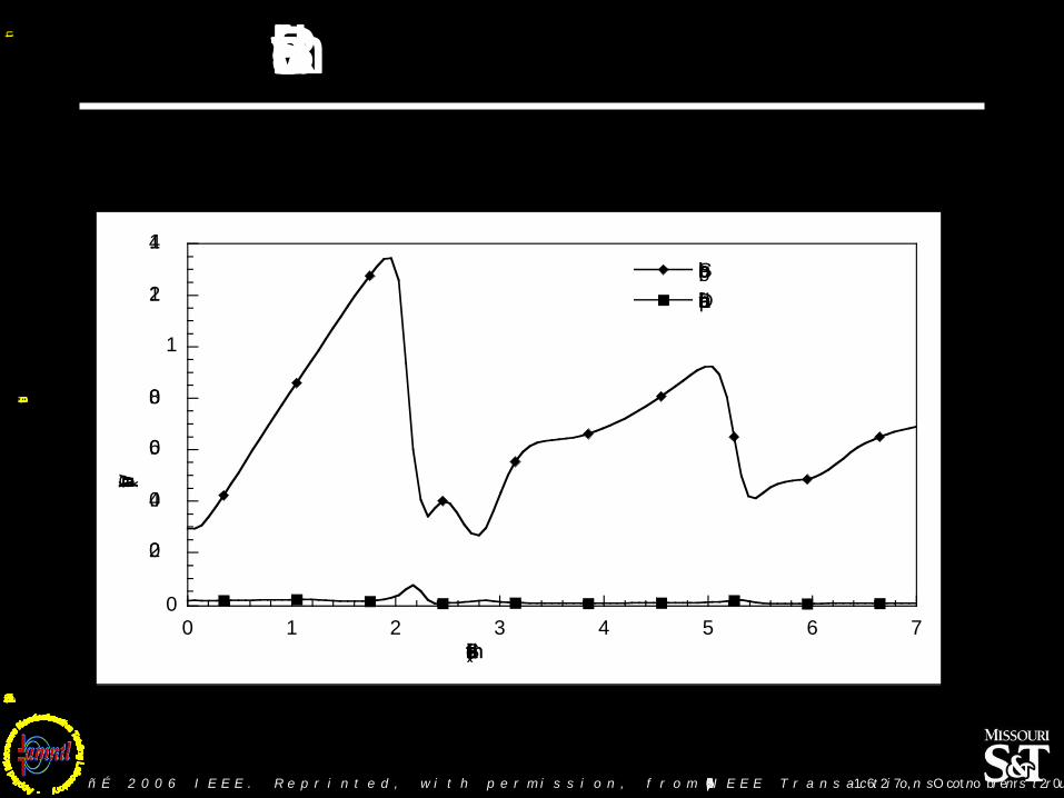
Standoff Removal
0
0.2
0.4
0.6
0.8
1
1.2
1.4
0 1 2 3 4 5 6 7
Single probe
Dual differential probe
Pro
be
ou
tpu
t (V
)
Standoff distance (mm)
ñÉ 2006 IEEE. Reprinted, with permission, from IEEE Transactions on Instrumentation and Measurement, vol. 55, no. 5, pp. 1620-1627, October 2006.ò

Copyin
g,
repro
ductio
n a
nd r
etr
ansm
issio
n o
f any p
ort
ion o
f th
is p
resenta
tio
n is N
OT
perm
itte
d w
ithout
expre
ssed w
ritt
en c
onse
nt
of th
e d
irecto
r.
Dual Probe vs. Single Probe
Natural PitsKa- Band Single Probe
Natural PitsV- Band Dual Probe
ñÉ 2006 IEEE. Reprinted, with permission, from IEEE Transactions on Instrumentation and Measurement, vol. 55, no. 5, pp. 1620-1627, October 2006.ò

Copyin
g,
repro
ductio
n a
nd r
etr
ansm
issio
n o
f any p
ort
ion o
f th
is p
resenta
tio
n is N
OT
perm
itte
d w
ithout
expre
ssed w
ritt
en c
onse
nt
of th
e d
irecto
r.
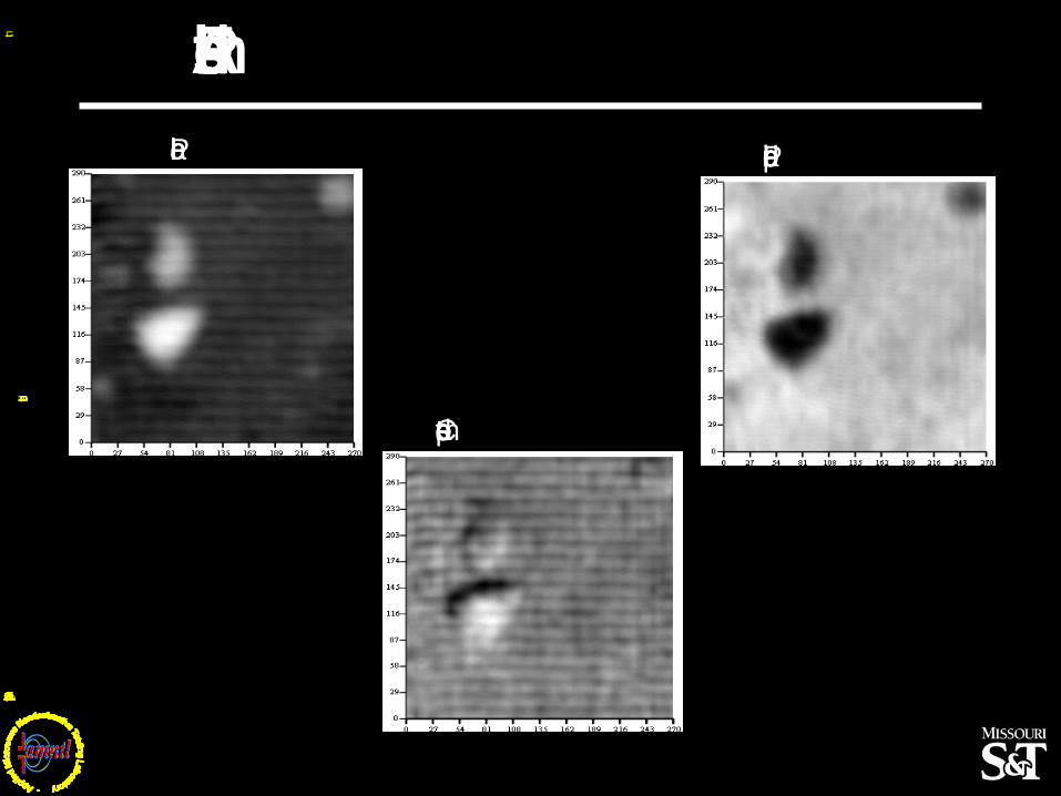
Corrosion under Paint
datawT
datawT
V-Band Single Probe V-Band Dual Probe
Reprinted with permission from M.T. Ghasr, S. Kharkovsky, R. Zoughi, M. OôKeefe and D. Palmer, ñMillimeter Wave Imaging of
Corrosion under Paint: Comparison of Two Probes,ò Review of Progress in Quantitative Nondestructive Evaluation 25B
AIP Conference Proceedings, vol. 820, pp. 447-454, 2006, Copyright 2006, American Institute of Physics.

Copyin
g,
repro
ductio
n a
nd r
etr
ansm
issio
n o
f any p
ort
ion o
f th
is p
resenta
tio
n is N
OT
perm
itte
d w
ithout
expre
ssed w
ritt
en c
onse
nt
of th
e d
irecto
r.
DUAL POLARIZATION
TECHNIQUE

Copyin
g,
repro
ductio
n a
nd r
etr
ansm
issio
n o
f any p
ort
ion o
f th
is p
resenta
tio
n is N
OT
perm
itte
d w
ithout
expre
ssed w
ritt
en c
onse
nt
of th
e d
irecto
r.
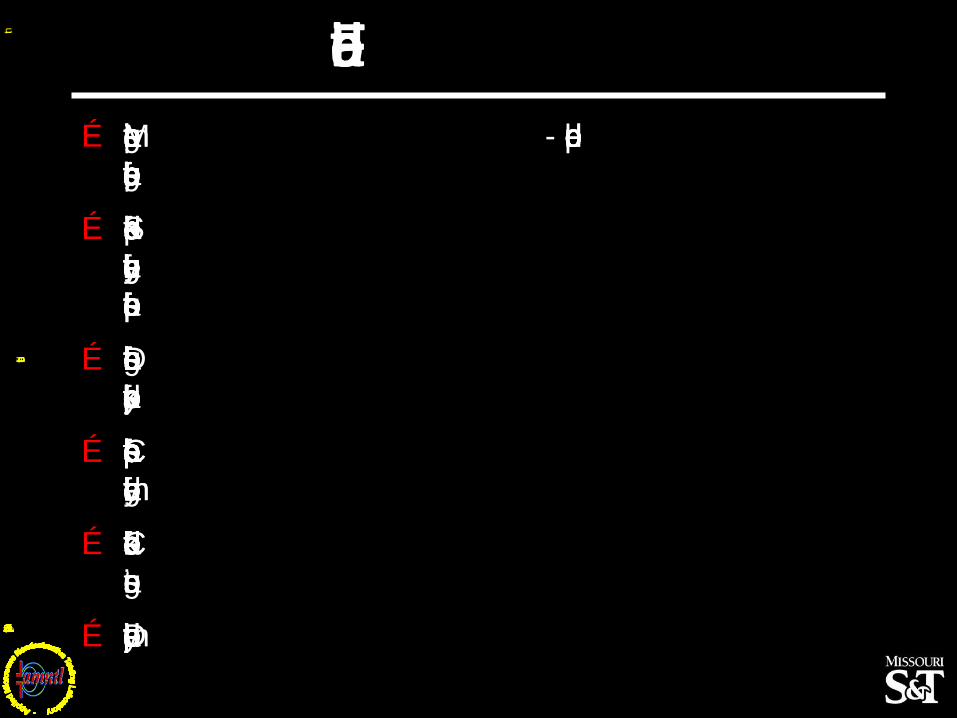
CFRP -Strengthened StructuresÉ Concrete structures may be
strengthened or rehabilitated with unidirectional CFRP sheets.
É Transmission through CFRP is highly polarization dependent.
É Two normal polarizations give different & useful information.
É Orthogonal polarization dependent of standoff and disbond.
É Parallel polarization data can be used to monitor and correct for standoff distance change.
ñÉ 2008 IEEE. Reprinted, with permission, from IEEE Transactions on Instrumentation and Measurement, vol. 57, no. 1, pp. 168-175, January 2008.ò

Copyin
g,
repro
ductio
n a
nd r
etr
ansm
issio
n o
f any p
ort
ion o
f th
is p
resenta
tio
n is N
OT
perm
itte
d w
ithout
expre
ssed w
ritt
en c
onse
nt
of th
e d
irecto
r.
Dual Polarized Probe
ñÉ 2008 IEEE. Reprinted, with permission, from IEEE Transactions on Instrumentation and Measurement, vol. 57, no. 1, pp. 168-175, January 2008.ò

Copyin
g,
repro
ductio
n a
nd r
etr
ansm
issio
n o
f any p
ort
ion o
f th
is p
resenta
tio
n is N
OT
perm
itte
d w
ithout
expre
ssed w
ritt
en c
onse
nt
of th
e d
irecto
r.
Dual Polarized Probe Video
Click on the above picture to view video

Copyin
g,
repro
ductio
n a
nd r
etr
ansm
issio
n o
f any p
ort
ion o
f th
is p
resenta
tio
n is N
OT
perm
itte
d w
ithout
expre
ssed w
ritt
en c
onse
nt
of th
e d
irecto
r.
Laboratory Results - Tilted
Parallel Perpendicular
Compensated
ñÉ 2008 IEEE. Reprinted, with permission, from IEEE Transactions on Instrumentation and Measurement, vol. 57, no. 1, pp. 168-175, January 2008.ò
dataxT
dataxT
dataxT

Copyin
g,
repro
ductio
n a
nd r
etr
ansm
issio
n o
f any p
ort
ion o
f th
is p
resenta
tio
n is N
OT
perm
itte
d w
ithout
expre
ssed w
ritt
en c
onse
nt
of th
e d
irecto
r.
Dual Polarized Probe
Copyin
g,
repro
ductio
n a
nd r
etr
ansm
issio
n o
f any p
ort
ion o
f th
is p
resenta
tio
n is N
OT
perm
itte
d w
ithout
expre
ssed w
ritt
en c
onse
nt
of th
e d
irecto
r.
Field Results Abutment
datax3Tdatax3
T
Parallel Perpendicular
data3( )T
Compensated

Copyin
g,
repro
ductio
n a
nd r
etr
ansm
issio
n o
f any p
ort
ion o
f th
is p
resenta
tio
n is N
OT
perm
itte
d w
ithout
expre
ssed w
ritt
en c
onse
nt
of th
e d
irecto
r.
DUAL MODULATED
APERTURE TECHNIQUE

Copyin
g,
repro
ductio
n a
nd r
etr
ansm
issio
n o
f any p
ort
ion o
f th
is p
resenta
tio
n is N
OT
perm
itte
d w
ithout
expre
ssed w
ritt
en c
onse
nt
of th
e d
irecto
r.
FoundationÉ Switch between two mirror electric field distributions
synthesized over a single aperture.
É Both distributions interact with their surroundings in a similar manner.
É By making one of them ON at a time, two signals can be measured at any point.
É Standoff distance variation can be compensated for by subtracting the measured signals. These signals are measured non- coherently using a standing wave probe.
0 a
b
0 a
b
0 a
b
Shorted Dipoles
(c)(b)(a)
ñÉ 2009 IEEE. Reprinted, with permission, from IEEE Transactions on Instrumentation and Measurement, vol. 58, no. 5, pp. 1273-1282, May 2009.ò

Copyin
g,
repro
ductio
n a
nd r
etr
ansm
issio
n o
f any p
ort
ion o
f th
is p
resenta
tio
n is N
OT
perm
itte
d w
ithout
expre
ssed w
ritt
en c
onse
nt
of th
e d
irecto
r.
Prototype Probe Aperture
a
b
s
E
Dipole
PIN Diode
SMT Capacitor DC Bias Line
Dipole Length ~3mm and Dipole Interspacing ~5.3 mm
ñÉ 2009 IEEE. Reprinted, with permission, from IEEE Transactions on Instrumentation and Measurement, vol. 58, no. 5, pp. 1273-1282, May 2009.ò

Copyin
g,
repro
ductio
n a
nd r
etr
ansm
issio
n o
f any p
ort
ion o
f th
is p
resenta
tio
n is N
OT
perm
itte
d w
ithout
expre
ssed w
ritt
en c
onse
nt
of th
e d
irecto
r.
Standoff Distance Response
Conducting plate
aperture
d
ñÉ 2009 IEEE. Reprinted, with permission, from IEEE Transactions on Instrumentation and Measurement, vol. 58, no. 5, pp. 1273-1282, May 2009.ò
0 0.5 1 1.5 2-0.25
-0.2
-0.15
-0.1
-0.05
0
0.05
0.1
d/l
Re
sp
onse
(V
)
Diode (1) ON
Diode (2) ON
Difference
Conducting plate
aperture
d

Copyin
g,
repro
ductio
n a
nd r
etr
ansm
issio
n o
f any p
ort
ion o
f th
is p
resenta
tio
n is N
OT
perm
itte
d w
ithout
expre
ssed w
ritt
en c
onse
nt
of th
e d
irecto
r.
2D Image ðTilted Panel
0 5 10 15 20 25 30 35
0
5
10
15
20
25
30
35
Dual Modulated Aperture Probe
0 5 10 15 20 25 30 35
0
5
10
15
20
25
30
35
Single Aperture Probe
ñÉ 2009 IEEE. Reprinted, with permission, from IEEE Transactions on Instrumentation and Measurement, vol. 58, no. 5, pp. 1273-1282, May 2009.ò

Copyin
g,
repro
ductio
n a
nd r
etr
ansm
issio
n o
f any p
ort
ion o
f th
is p
resenta
tio
n is N
OT
perm
itte
d w
ithout
expre
ssed w
ritt
en c
onse
nt
of th
e d
irecto
r.
SURFACE CRACKDETECTION
andEVALUATION
Copyin
g,
repro
ductio
n a
nd r
etr
ansm
issio
n o
f any p
ort
ion o
f th
is p
resenta
tio
n is N
OT
perm
itte
d w
ithout
expre
ssed w
ritt
en c
onse
nt
of th
e d
irecto
r.
FoundationÉ Metals terminating an open - ended probe
aperture, cause total reflection of signal.
É Surface cracks perturb induced surface currents, thereby changing the reflection properties of the surface.
É Detection of changes in the reflection properties yields the presence of a crack.
É Characteristics of the reflection properties yield geometrical information.
É Can detect filled cracks and those under coatings.
É Detection is metal type independent.