Microstrip Patch Antenna Design -
19
SCU Center for Analog Design and Research Microstrip Patch Antenna Design Principles Ben Horwath
Transcript of Microstrip Patch Antenna Design -
SCU Center for Analog Design and Research
Microstrip Patch Antenna
Design Principles
Ben Horwath

SCU Center for Analog Design and Research
Outline • Introduction
• Antenna basics
• Microstrip antennas
• Design methodology
• Design guidelines
• Footprint equations
• Circuit equivalent equations
• Quick example
• EM solvers
• PhD work-to-date
• Future efforts
• Some good references
• Questions
SCU Center for Analog Design and Research
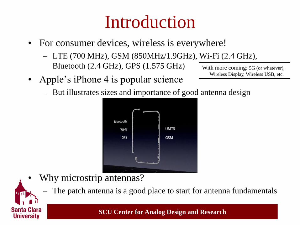
Introduction • For consumer devices, wireless is everywhere!
– LTE (700 MHz), GSM (850MHz/1.9GHz), Wi-Fi (2.4 GHz),
Bluetooth (2.4 GHz), GPS (1.575 GHz)
• Apple’s iPhone 4 is popular science
– But illustrates sizes and importance of good antenna design
• Why microstrip antennas?
– The patch antenna is a good place to start for antenna fundamentals
With more coming: 5G (or whatever),
Wireless Display, Wireless USB, etc.
SCU Center for Analog Design and Research
-1
-0.8
-0.6
-0.4
-0.2
0
0.2
0.4
0.6
0.8
1
0 0.25 0.5 0.75 1 1.25 1.5 1.75 2
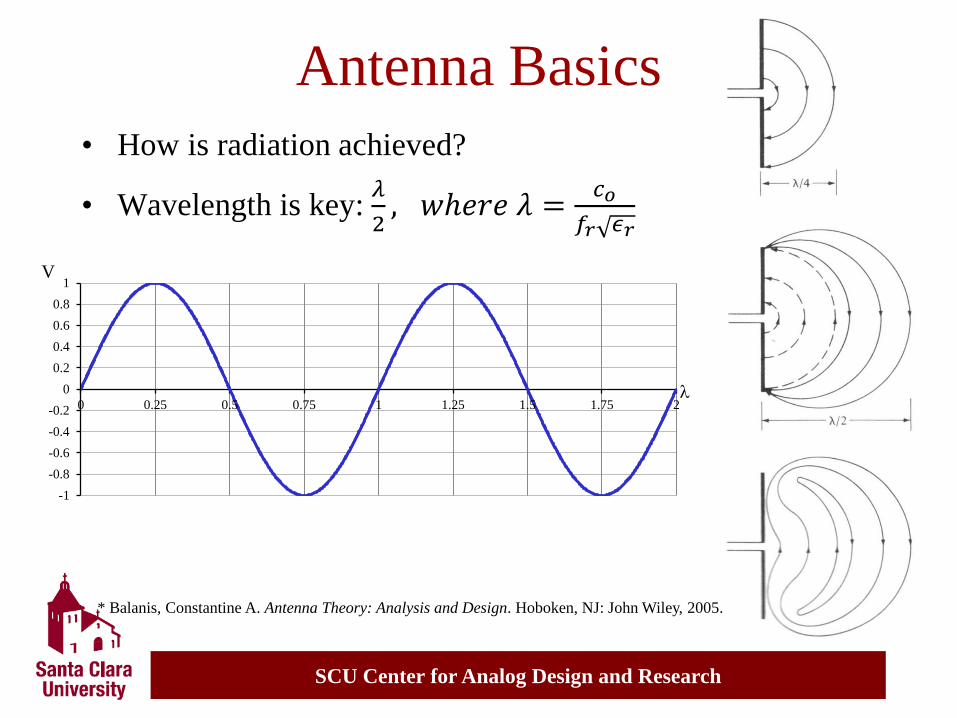
Antenna Basics
• How is radiation achieved?
• Wavelength is key: 𝜆
2, 𝑤ℎ𝑒𝑟𝑒 𝜆 =
𝑐𝑜
𝑓𝑟 𝜖𝑟
* Balanis, Constantine A. Antenna Theory: Analysis and Design. Hoboken, NJ: John Wiley, 2005.
l
V
SCU Center for Analog Design and Research
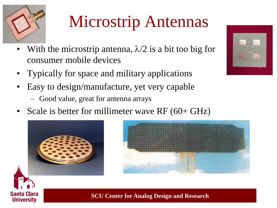
• With the microstrip antenna, l/2 is a bit too big for
consumer mobile devices
• Typically for space and military applications
• Easy to design/manufacture, yet very capable
– Good value, great for antenna arrays
• Scale is better for millimeter wave RF (60+ GHz)
Microstrip Antennas

SCU Center for Analog Design and Research
Design Methodology • Find a “comfortable” model
– Transmission Line – easiest, can be done in Excel
– Cavity – higher accuracy, higher complexity
– Full Wave – very accurate/adaptable, super complex
• Using specifications, generate initial design
– Resonance frequency, gain, substrate, footprint, etc.
• Compare with an EM solver
– Tune parameters such as ereff and DL (more details soon)
• Re-iterate design, prototype, measure
• Finalize design for manufacturing
SCU Center for Analog Design and Research
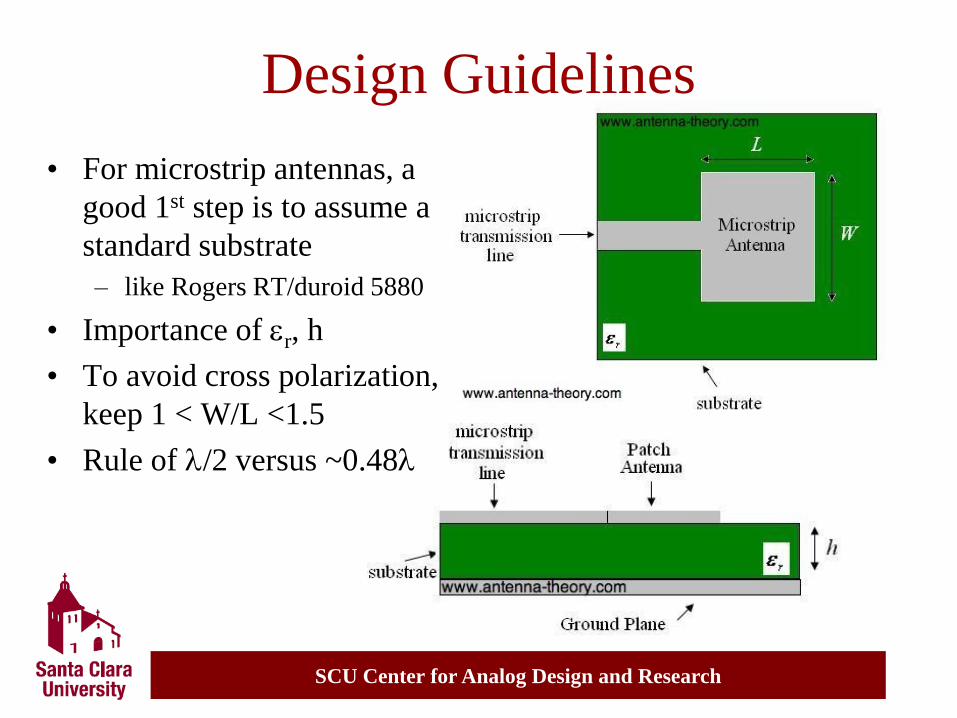
Design Guidelines
• For microstrip antennas, a
good 1st step is to assume a
standard substrate
– like Rogers RT/duroid 5880
• Importance of er, h
• To avoid cross polarization,
keep 1 < W/L <1.5
• Rule of l/2 versus ~0.48l
SCU Center for Analog Design and Research
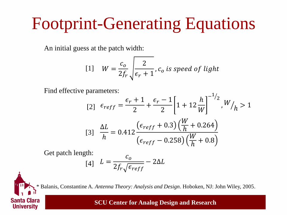
Footprint-Generating Equations
𝜖𝑟𝑒𝑓𝑓 =𝜖𝑟 + 1
2+𝜖𝑟 − 1
21 + 12
ℎ
𝑊
−1 2
,𝑊 ℎ > 1
𝑊 =𝑐𝑜2𝑓𝑟
2
𝜖𝑟 + 1, 𝑐𝑜 𝑖𝑠 𝑠𝑝𝑒𝑒𝑑 𝑜𝑓 𝑙𝑖𝑔ℎ𝑡
An initial guess at the patch width:
Find effective parameters:
∆𝐿
ℎ= 0.412
𝜖𝑟𝑒𝑓𝑓 + 0.3𝑊ℎ+ 0.264
𝜖𝑟𝑒𝑓𝑓 − 0.258𝑊ℎ+ 0.8
𝐿 =𝑐𝑜
2𝑓𝑟 𝜖𝑟𝑒𝑓𝑓− 2∆𝐿
Get patch length:
[1]
[2]
[3]
[4]
* Balanis, Constantine A. Antenna Theory: Analysis and Design. Hoboken, NJ: John Wiley, 2005.
SCU Center for Analog Design and Research
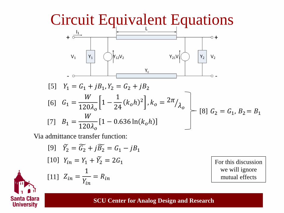
Circuit Equivalent Equations
𝐺1 =𝑊
120𝜆𝑜1 −
1
24𝑘𝑜ℎ
2 , 𝑘𝑜 =2𝜋𝜆𝑜
𝑌1 = 𝐺1 + 𝑗𝐵1, 𝑌2 = 𝐺2 + 𝑗𝐵2 [5]
[6]
[7] 𝐵1 =𝑊
120𝜆𝑜1 − 0.636 ln 𝑘𝑜ℎ
𝐺2 = 𝐺1, 𝐵2= 𝐵1 [8]
Via admittance transfer function:
𝑌2 = 𝐺2 + 𝑗𝐵2 = 𝐺1 − 𝑗𝐵1 [9]
𝑌𝑖𝑛 = 𝑌1 + 𝑌2 = 2𝐺1 [10]
𝑍𝑖𝑛 =1
𝑌𝑖𝑛= 𝑅𝑖𝑛 [11]
For this discussion
we will ignore
mutual effects
SCU Center for Analog Design and Research
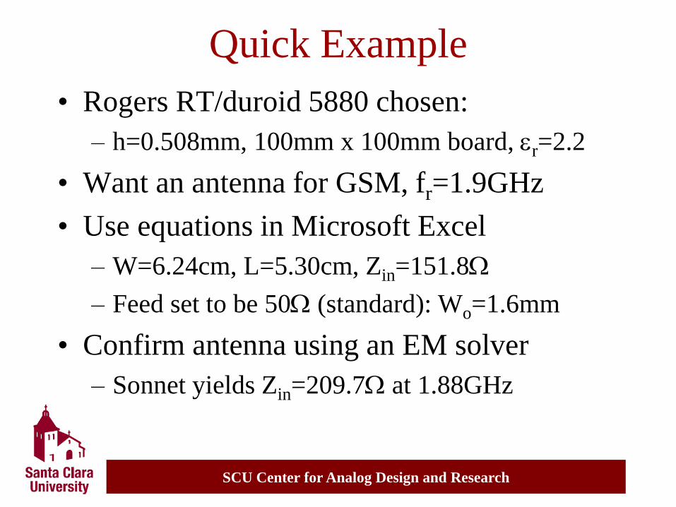
Quick Example
• Rogers RT/duroid 5880 chosen:
– h=0.508mm, 100mm x 100mm board, er=2.2
• Want an antenna for GSM, fr=1.9GHz
• Use equations in Microsoft Excel
– W=6.24cm, L=5.30cm, Zin=151.8W
– Feed set to be 50W (standard): Wo=1.6mm
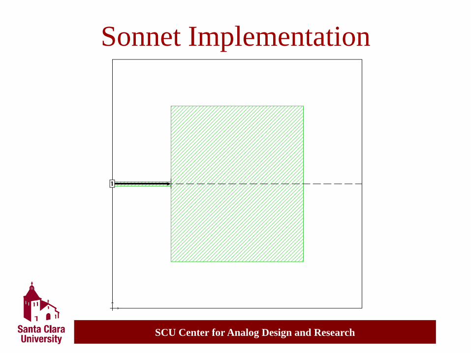
• Confirm antenna using an EM solver
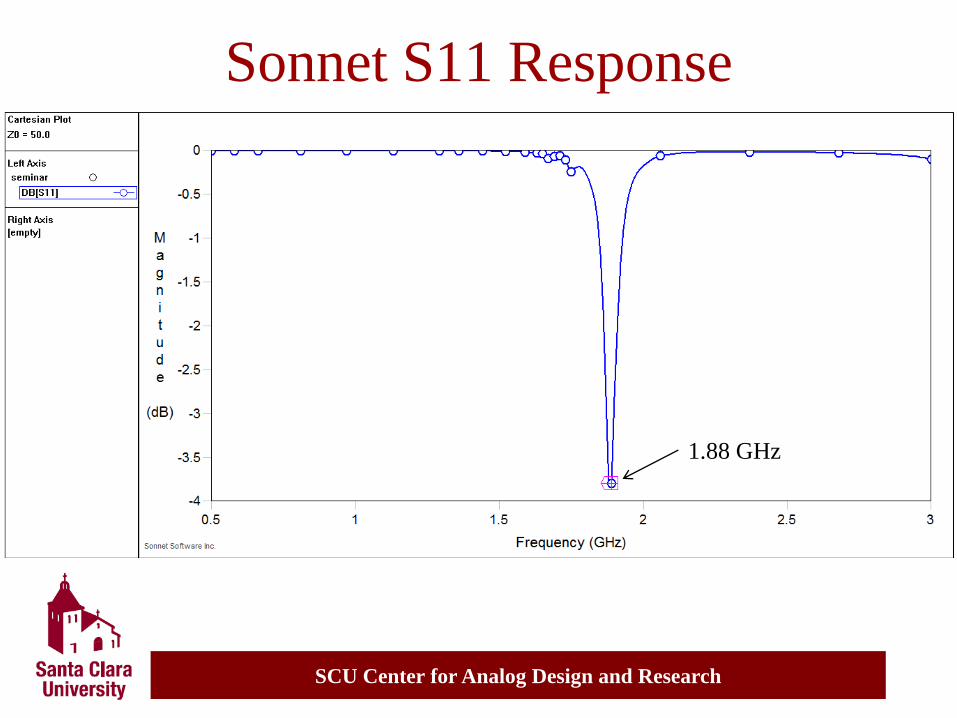
– Sonnet yields Zin=209.7W at 1.88GHz
SCU Center for Analog Design and Research
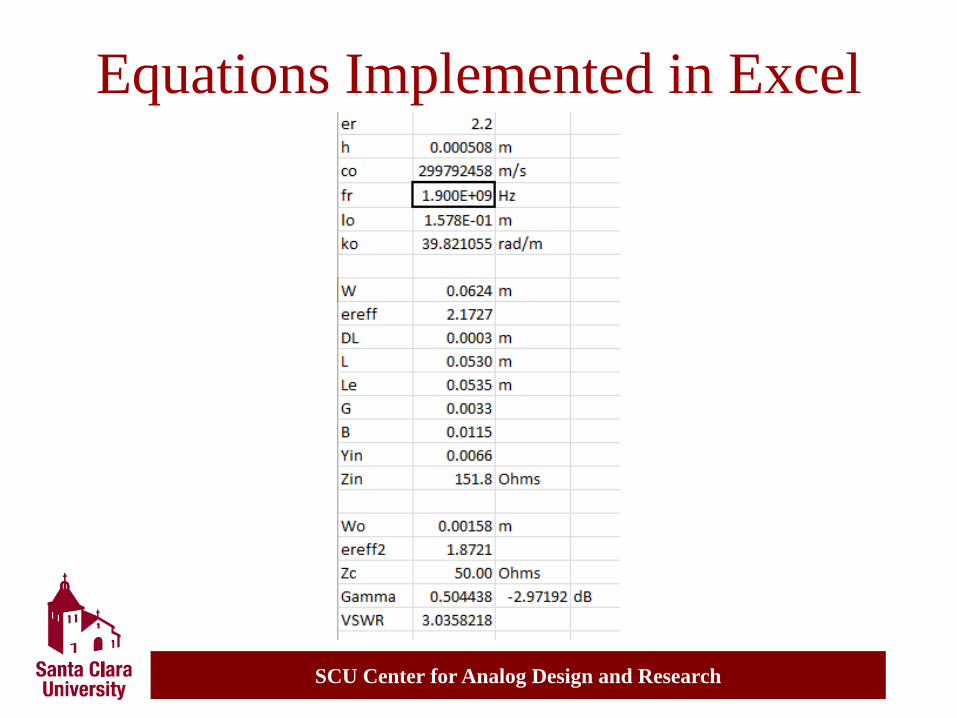
Equations Implemented in Excel
SCU Center for Analog Design and Research
Sonnet Implementation
SCU Center for Analog Design and Research
Sonnet S11 Response
1.88 GHz
SCU Center for Analog Design and Research
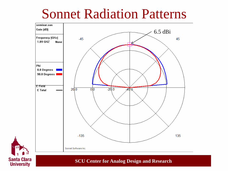
Sonnet Radiation Patterns 6.5 dBi

SCU Center for Analog Design and Research
A Few EM Solvers
Microwave Office (AXIEM)
HFSS
ADS
*
*
*
*
* SCU Design Center
SCU Center for Analog Design and Research
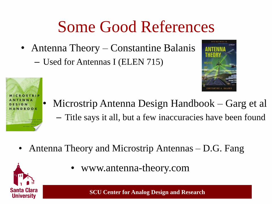
Some Good References
• Antenna Theory and Microstrip Antennas – D.G. Fang
• Microstrip Antenna Design Handbook – Garg et al
– Title says it all, but a few inaccuracies have been found
• Antenna Theory – Constantine Balanis
– Used for Antennas I (ELEN 715)
• www.antenna-theory.com
SCU Center for Analog Design and Research
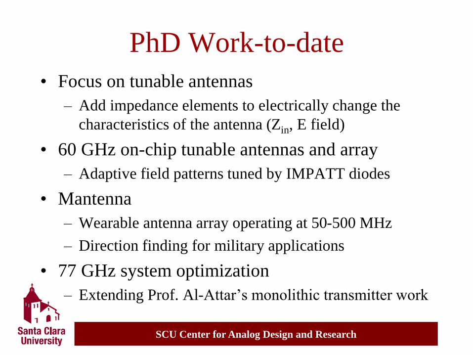
PhD Work-to-date
• Focus on tunable antennas
– Add impedance elements to electrically change the
characteristics of the antenna (Zin, E field)
• 60 GHz on-chip tunable antennas and array
– Adaptive field patterns tuned by IMPATT diodes
• Mantenna
– Wearable antenna array operating at 50-500 MHz
– Direction finding for military applications
• 77 GHz system optimization
– Extending Prof. Al-Attar’s monolithic transmitter work
SCU Center for Analog Design and Research
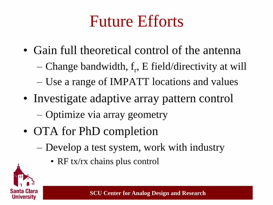
Future Efforts
• Gain full theoretical control of the antenna
– Change bandwidth, fr, E field/directivity at will
– Use a range of IMPATT locations and values
• Investigate adaptive array pattern control
– Optimize via array geometry
• OTA for PhD completion
– Develop a test system, work with industry
• RF tx/rx chains plus control

SCU Center for Analog Design and Research
Questions?
Contact Info:
Ben Horwath
www.horwathtech.com