MicroNet™ Plus & TMR - · PDF fileCreated specifically for high speed application of...
26
MicroNet™ Plus & TMR 26 th Feb. 2011 User Group Seminar - Saudi Aramco - RTR CONTROLLING the power of ENERGY This presentation is intended only for the individual or entity to which it is addressed and may contain information that is the Confidential and/or Proprietary Information of Woodward Governor Company, the disclosure of which may be in violation of applicable law. If you are not the intended recipient, or an employee or agent responsible for delivery to the intended recipient, you are hereby notified that any dissemination, distribution, or copying of this message is strictly prohibited and you are requested to notify us immediately by telephone.
Transcript of MicroNet™ Plus & TMR - · PDF fileCreated specifically for high speed application of...

TM
MicroNet™ Plus & TMR 26th Feb. 2011
User Group Seminar - Saudi Aramco - RTR
CONTROLLING the power of ENERGY
This presentation is intended only for the individual or entity to which it is addressed and may contain information that is the Confidential and/or Proprietary Information of
Woodward Governor Company, the disclosure of which may be in violation of applicable law. If you are not the intended recipient, or an employee or agent responsible for
delivery to the intended recipient, you are hereby notified that any dissemination, distribution, or copying of this message is strictly prohibited and you are requested to notify
us immediately by telephone.

Topics of Presentation
(2)
PROPRIETARY INFORMATION
MicroNet™ Application Overview.
MicroNet™ Chassis and Module Architecture.
TMR Voting structure.
DCS Networking & MicroNet™ Plus.
GAP™ & Software Determinism.

Compressor Compressor
PT
PT
FT
PT
FT
Discharge Pressure No. 2
Side stream Pressure
Side stream Flow
Suction Pressure No. 1
Suction Flow No. 1
Recycle Valve No. 2
Recycle Valve No. 1
motor current Signal
Torque converter or Gear Throttle Valve
Speed input Signal
Programmable Discrete Inputs
Programmable Analog Inputs
Programmable Discrete Outputs
Programmable Analog Outputs
AI
AO
DO
Ethernet, RS232, RS422, RS485 Ports
MicroNet™ Plus
For
Motor Driven Compressor
DCS and Eng Work Station
(3)
PROPRIETARY INFORMATION

Compressor Compressor
PT
PT
FT
PT
FT
Discharge Pressure No. 2
Side stream Pressure
Side stream Flow
Suction Pressure No. 1
Suction Flow No. 1
Recycle Valve No. 2
Recycle Valve No. 1
Programmable Discrete Inputs
Programmable Analog Inputs
Programmable Discrete Outputs
Programmable Analog Outputs
AI
AO
DO
Ethernet, RS232, RS422, RS485 Ports
DCS and Eng Work Station
Compressor Discharge Pressure
Turbine Inlet Temperature
Gas Generator Speed
Fuel Valve Demand Signal
Power Turbine Speed
Exhaust Gas Temperature
(4)
PROPRIETARY INFORMATION
MicroNet™ Plus For
Integrated Turbine &
Compressor Control

PT
T&T Valve PT
Exhaust Pressure Signal
PT
PT
HP
LP IP
HP Actuator Demand Signal
IP Actuator Demand Signal
LP Actuator Demand Signal
Turbine Speed
LP Extraction Pressure Signal
HP Extraction Pressure Signal
Inlet Pressure Signal
Generator
PTs &
CTs
DCS / OCP
505DE
Watt
Xducer
Synchronizer
E.W.S
MicroNet™ Plus for STG controls

MicroNet™ TMR MicroNet™ Plus
MicroNet™ Hardware
(6)
PROPRIETARY INFORMATION

MicroNet™ Plus Hardware
(7)
PROPRIETARY INFORMATION
Power Supply Module
CPU
I/O Modules (6 or 12)
CPU – 2nd
Power Supply – 2nd
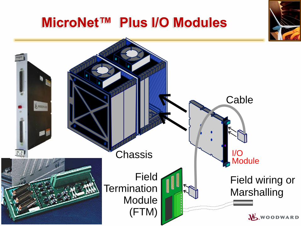
MicroNet™ Plus I/O Modules
(8)
PROPRIETARY INFORMATION
Cable
I/O Module
Field Termination
Module (FTM)
Field wiring or
Marshalling
Chassis

MicroNet™ Hardware
(9)
PROPRIETARY INFORMATION
I/O A
I/O B
FTM
FTM
Field Device
Field Device
Card level redundancy lost does not mean Field level redundancy lost
MicroNet™ Hardware
(10)
PROPRIETARY INFORMATION
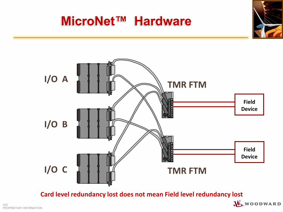
I/O A
I/O B
I/O C
TMR FTM
TMR FTM
Field Device
Field Device
Card level redundancy lost does not mean Field level redundancy lost
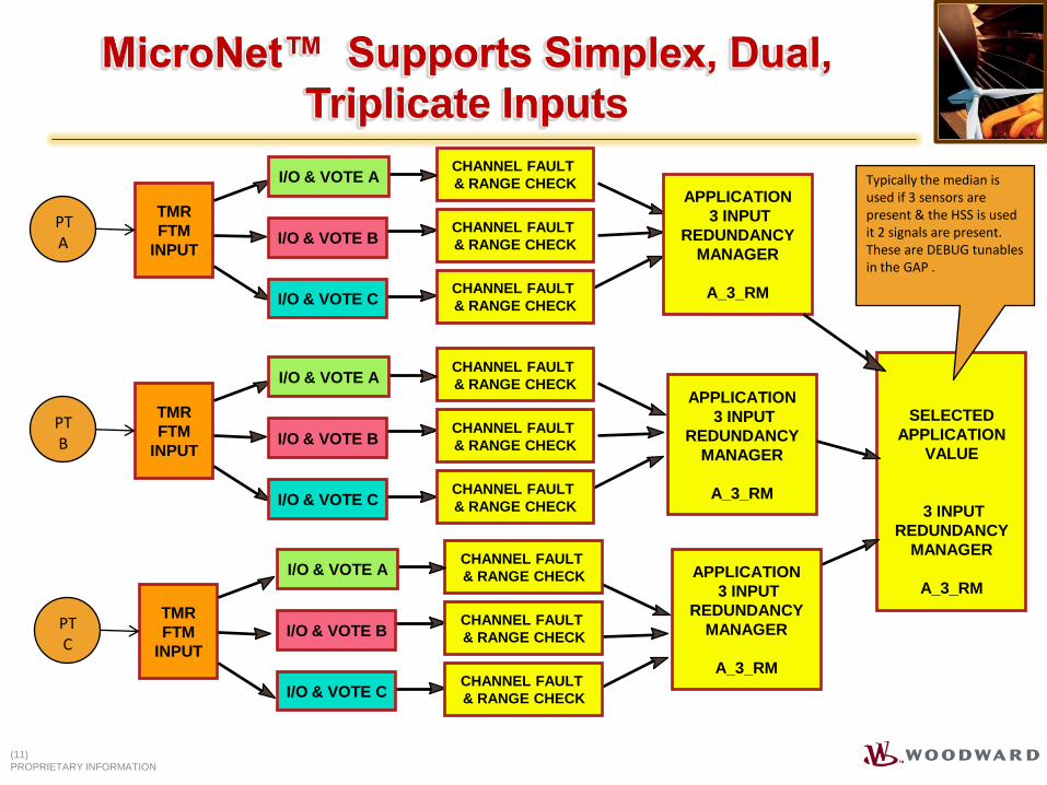
MicroNet™ Supports Simplex, Dual,
Triplicate Inputs
APPLICATION
3 INPUT
REDUNDANCY
MANAGER
A_3_RM
TMR
FTM
INPUT
PTB
TMR
FTM
INPUT
PTC
SELECTED
APPLICATION
VALUE
3 INPUT
REDUNDANCY
MANAGER
A_3_RM APPLICATION
3 INPUT
REDUNDANCY
MANAGER
A_3_RM
CHANNEL FAULT
& RANGE CHECK
CHANNEL FAULT
& RANGE CHECK
CHANNEL FAULT
& RANGE CHECK
I/O & VOTE A
I/O & VOTE B
I/O & VOTE C
CHANNEL FAULT
& RANGE CHECK
CHANNEL FAULT
& RANGE CHECK
CHANNEL FAULT
& RANGE CHECK
I/O & VOTE A
I/O & VOTE B
I/O & VOTE C
Typically the median is used if 3 sensors are present & the HSS is used it 2 signals are present. These are DEBUG tunables in the GAP .
TMR
FTM
INPUT
PTA
CHANNEL FAULT
& RANGE CHECK
CHANNEL FAULT
& RANGE CHECK
CHANNEL FAULT
& RANGE CHECK
I/O & VOTE A
I/O & VOTE B
I/O & VOTE C
APPLICATION
3 INPUT
REDUNDANCY
MANAGER
A_3_RM
(11)
PROPRIETARY INFORMATION
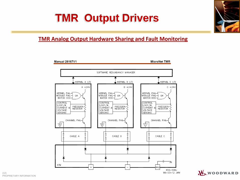
TMR Output Drivers
TMR Analog Output Hardware Sharing and Fault Monitoring
(12)
PROPRIETARY INFORMATION

Motorola 5200 CPU Card Reset Sw & LED
2 Ethernet Ports
2 Real Time Net Pt
Woodward Debug Pt
Status LEDs
Serial Comm. Port
CAN Ports
COMPUTING POWER 700 mips @ 400MHz MEMORY 64 MB Flash - 128 MB RAM Supports multiple GAP Applications Supports multiple data logs Program Loading On Board Ethernet port - 10/100 BPS AppManager via Ethernet port VX-Works Operating System Communication Network Modbus Serial link – ASCII or Binary, Servlink Modbus Ethernet – UDP or TCP/IP Built in OPC – 10/100 Base T, Real Time
MicroNet™ Plus – CPU 5200
(13)
PROPRIETARY INFORMATION
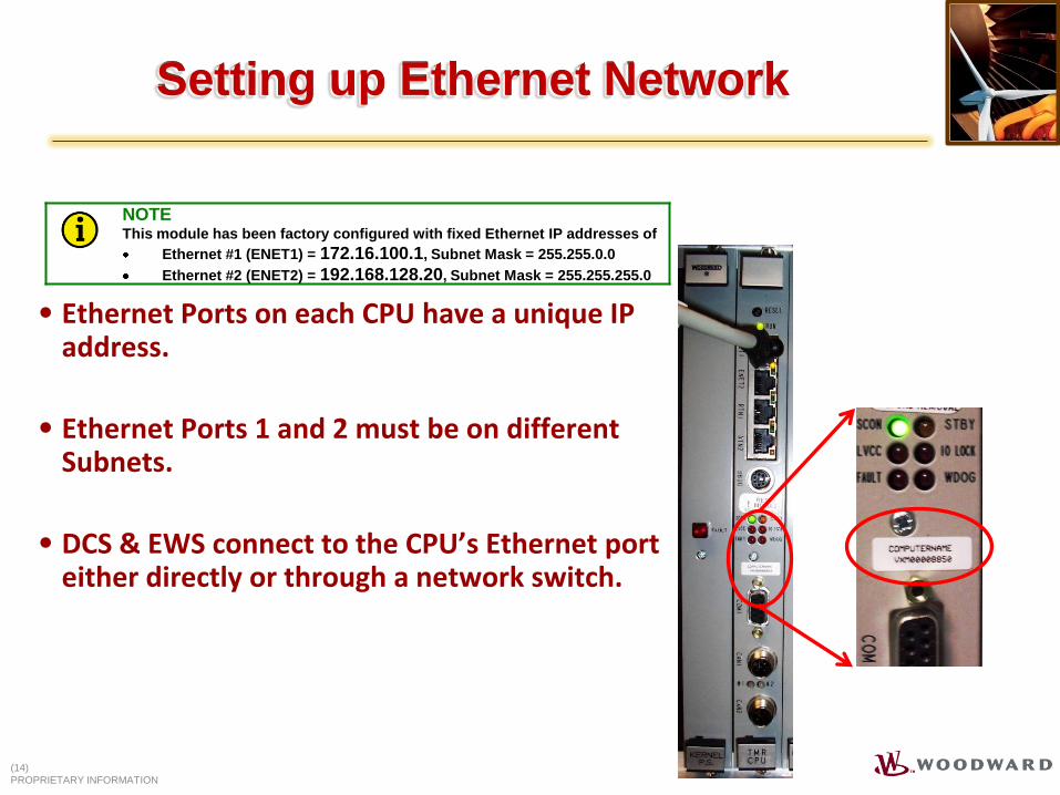
Setting up Ethernet Network
(14)
PROPRIETARY INFORMATION
• Ethernet Ports on each CPU have a unique IP address.
• Ethernet Ports 1 and 2 must be on different Subnets.
• DCS & EWS connect to the CPU’s Ethernet port either directly or through a network switch.
NOTE This module has been factory configured with fixed Ethernet IP addresses of
Ethernet #1 (ENET1) = 172.16.100.1, Subnet Mask = 255.255.0.0
Ethernet #2 (ENET2) = 192.168.128.20, Subnet Mask = 255.255.255.0
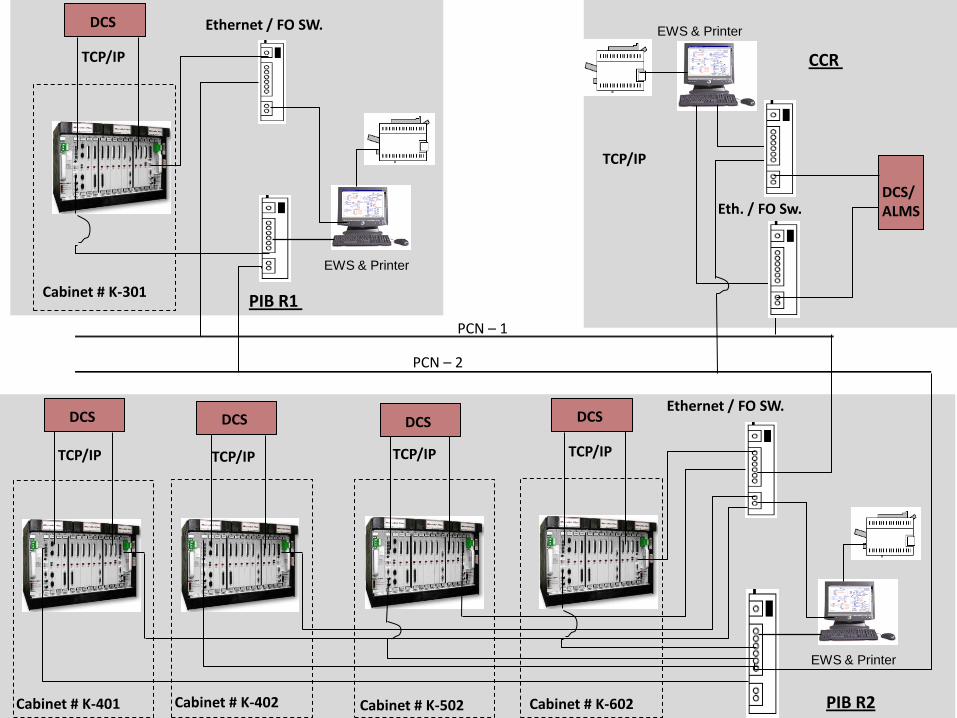
TCP/IP
EWS & Printer
PCN – 1
PCN – 2
PIB R2 Cabinet # K-402 Cabinet # K-602
Ethernet / FO SW.
Eth. / FO Sw.
Cabinet # K-502
CCR
DCS/ ALMS
EWS & Printer
Cabinet # K-401
DCS DCS DCS DCS
TCP/IP TCP/IP TCP/IP TCP/IP
PIB R1 Cabinet # K-301
Ethernet / FO SW.
EWS & Printer
DCS
TCP/IP
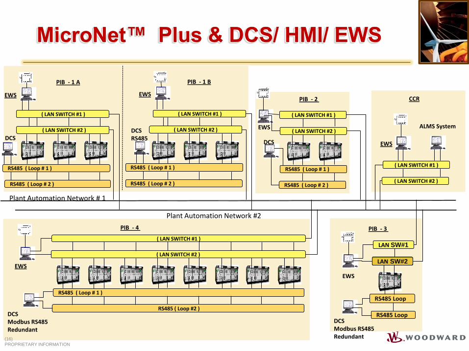
Plant Automation Network #2
( LAN SWITCH #2 )
RS485 ( Loop # 1 )
RS485 ( Loop #2 )
( LAN SWITCH #1 )
EWS
LAN SW#1
LAN SW#2
RS485 Loop
RS485 Loop
EWS ( LAN SWITCH #2 )
RS485 ( Loop # 1 )
( LAN SWITCH #1 )
RS485 ( Loop # 2 )
EWS
ALMS System
( LAN SWITCH #1 )
( LAN SWITCH #2 )
DCS Modbus RS485 Redundant
DCS
DCS Modbus RS485 Redundant
PIB - 4
PIB - 2
PIB - 3
EWS
CCR
Plant Automation Network # 1
( LAN SWITCH #1 )
DCS
PIB - 1 A
EWS
( LAN SWITCH #1 )
( LAN SWITCH #2 ) ( LAN SWITCH #2 )
RS485 ( Loop # 1 ) RS485 ( Loop # 1 )
RS485 ( Loop # 2 ) RS485 ( Loop # 2 )
DCS RS485
EWS
PIB - 1 B
MicroNet™ Plus & DCS/ HMI/ EWS
(16)
PROPRIETARY INFORMATION
GAP™ (Graphical Application Programmer )
17
A Windows™ based, high level, block-oriented programming language (IEC 1131)
Deterministic behavior (rate groups)
Self-documenting (Pictures-to-Code)
Created specifically for high speed application of turbine & compressor control.
The GAP™ program has sophisticated algorithms and timing control that have been rigorously proven at Woodward (since 1984)
The GAP ™ program allows engineers and field service personnel to concentrate on control engineering instead of software development
Facilitates Code Reuse – Graphical applications are easily portable to new hardware platforms
Real Time Operating System (RTOS)

Graphical Application Program
(18)
PROPRIETARY INFORMATION
18
Proprietary Information
• Monitor GAP uses SOS to communicate to the control for live updates to block outputs.

Software Determinism
(19)
PROPRIETARY INFORMATION
• Typical Definition of Determinism Doing the same thing at the same time, every time, for a given
application.
• Loading Affects Determinism Adding tasks to the program may change its deterministic nature as it
adds execution time.
Since each task is performed at a different time interval, the total execution time of all the tasks changes.
This changes the recursion rate to a new value, which is different but still deterministic.
Are the system’s dynamics effected?
Task 1,2,3,...lastTask 1,2,3,...last Task 1,2,3,...last Task 1,2,3,...last
X time X timeX timeX time
Task 1,2,3,.last+1
X+1 time
Task 1,2,3,.last+1 Task 1,2,3,.last+1 Task 1,2,3,.last+1
X+1 time X+1 time X+1 time
Software Determinism
(20)
PROPRIETARY INFORMATION
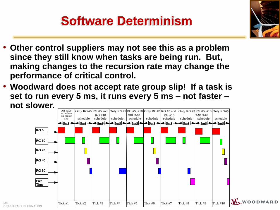
• Other control suppliers may not see this as a problem since they still know when tasks are being run. But, making changes to the recursion rate may change the performance of critical control.
• Woodward does not accept rate group slip! If a task is set to run every 5 ms, it runs every 5 ms – not faster – not slower.
All RGs
schedule
on major
Only RG
#5
schedule
RG #5 and
RG #10
schedule
Only RG
#5
schedule
RG #5, #10
and
#20Schedul
Only RG
#5
schedule
RG #5 and
RG #10
schedule
Only RG
#5
schedule
RG #5, #10
#20, #40
schedule
Only RG
#5
schedule
RG 5
RG 10
RG 20
RG 40
RG 80
Free
Time
5mS
Tick #2
5mS
Tick #3
5mS
Tick #4
5mS
Tick #5
5mS
Tick #6
5mS
Tick #7
5mS
Tick #8
5mS
Tick #9
5mS
Tick #1
5mS
Tick #10
All RGs
schedule
on major
Only RG
#5
schedule
RG #5 and
RG #10
schedule
Only RG
#5
schedule
RG #5, #10
and
#20Schedul
Only RG
#5
schedule
RG #5 and
RG #10
schedule
Only RG
#5
schedule
RG #5, #10
#20, #40
schedule
Only RG
#5
schedule
All RGsscheduleon major
tick
Only RG#5
schedule
RG #5 and
RG #10schedule
Only RG#5
schedule
RG #5, #10
and #20
schedule
Only RG#5
schedule
RG #5 and
RG #10schedule
Only RG #5
schedule
RG #5, #10
#20, #40
schedule
Only RG#5
schedule
RG 5
RG 10
RG 20
RG 40
RG 80
Free
Time
5mS
Tick #2
5mS
Tick #3
5mS
Tick #4
5mS
Tick #5
5mS
Tick #6
5mS
Tick #7
5mS
Tick #8
5mS
Tick #9
5mS
Tick #1
5mS
Tick #10
RG 5
RG 10
RG 20
RG 40
RG 80
Free
Time
RG 5
RG 10
RG 20
RG 40
RG 80
Free
Time
5mS
Tick #2
5mS
Tick #3
5mS
Tick #4
5mS
Tick #5
5mS
Tick #6
5mS
Tick #7
5mS
Tick #8
5mS
Tick #9
5mS
Tick #1
5mS
Tick #10
5mS
Tick #2
5mS
Tick #2
5mS
Tick #3
5mS
Tick #3
5mS
Tick #4
5mS
Tick #4
5mS
Tick #5
5mS
Tick #5
5mS
Tick #6
5mS
Tick #6
5mS
Tick #7
5mS
Tick #7
5mS
Tick #8
5mS
Tick #8
5mS
Tick #9
5mS
Tick #9
5mS
Tick #1
5mS
Tick #1
5mS
Tick #10
5mS
Tick #10

Software Determinism
(21)
PROPRIETARY INFORMATION
• Execution Order Enhances Determinism
Being able to define the specific execution order in
which tasks are performed assures that the proper
information is used by subsequent tasks.
Task 2Task 1 Task 9Task 8
Task 5Task 4Task 3
Task 7Task 6Task 10
Scan Time effect 10mSec. Vs 160mSec :
Software – 10mSec Rate Group
(22)
PROPRIETARY INFORMATION
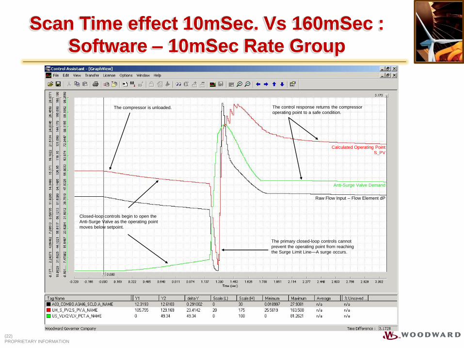
Anti-Surge Valve Demand
Calculated Operating Point
S_PV
Raw Flow Input – Flow Element dP
The control response returns the compressor
operating point to a safe condition.
The primary closed-loop controls cannot
prevent the operating point from reaching
the Surge Limit Line—A surge occurs.
The compressor is unloaded.
Closed-loop controls begin to open the
Anti-Surge Valve as the operating point
moves below setpoint.
Scan Time effect 10mSec. Vs 160mSec :
Software – 160mSec Rate Group
(23)
PROPRIETARY INFORMATION
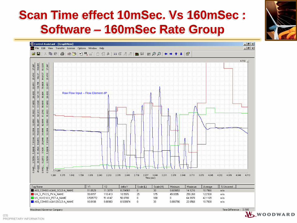
Raw Flow Input – Flow Element dP

Scan Time effect 10mSec. Vs 160mSec :
Result
(24)
PROPRIETARY INFORMATION
Number of undetected surges 0 9
Number of surges after initial detection 0 1
Time to initial detection 50ms 1400ms
Time from detection to recovery 74ms 322ms
• Recursion rate conclusions:
10ms Control 160ms Control

MicroNet™ Safety Certification
(25)
PROPRIETARY INFORMATION

TM
THANK YOU