Microcontroller Programming LMP7: Driving …data.mecheng.adelaide.edu.au/robotics/ Programming...
4
Microcontroller Programming LMP7: Driving stepper motors 1 Objectives - To program a generic software driver for a stepper motor - Set-point data should be read from serial communication interface SCI1; this data could be the period of the driving pulse train signal - Positive set-point values are to be interpreted as clockwise rotation; negative set- points are to be interpreted as anti-clockwise rotation Introduction Stepper motors are among the most frequently used actuators of robotics and mechatronics applications. A simple stepper motor driver only requires a small number of inexpensive electronic components such as transistors (power MOSFETs) and a few NAND gates. An example circuit is shown in Figure LMP7-1 with the circuit diagram in Figure LMP7-2. The control of such as driver can easily be done with a small microcontroller. In the course of this laboratory session we will design a small software driver which produces a pulse train signal with a user programmable period. The transistors of the hardware driver are switched with every falling edge of the control signal. Therefore, the period of this signal governs the speed of the motor. A second control signal is used to specify the direction of rotation (clockwise / anti-clockwise). The software driver should accept set-point data from a host-based terminal program connected to serial communication interface SCI1 of the MC9S12DP256B/C. Figure LMP7-1 A simple stepper motor driver
-
Upload
trinhxuyen -
Category
Documents
-
view
221 -
download
0
Transcript of Microcontroller Programming LMP7: Driving …data.mecheng.adelaide.edu.au/robotics/ Programming...

Microcontroller Programming LMP7: Driving stepper motors
1
Objectives - To program a generic software driver for a stepper motor - Set-point data should be read from serial communication interface SCI1; this data
could be the period of the driving pulse train signal - Positive set-point values are to be interpreted as clockwise rotation; negative set-
points are to be interpreted as anti-clockwise rotation
Introduction Stepper motors are among the most frequently used actuators of robotics and mechatronics applications. A simple stepper motor driver only requires a small number of inexpensive electronic components such as transistors (power MOSFETs) and a few NAND gates. An example circuit is shown in Figure LMP7-1 with the circuit diagram in Figure LMP7-2. The control of such as driver can easily be done with a small microcontroller. In the course of this laboratory session we will design a small software driver which produces a pulse train signal with a user programmable period. The transistors of the hardware driver are switched with every falling edge of the control signal. Therefore, the period of this signal governs the speed of the motor. A second control signal is used to specify the direction of rotation (clockwise / anti-clockwise). The software driver should accept set-point data from a host-based terminal program connected to serial communication interface SCI1 of the MC9S12DP256B/C.
Figure LMP7-1 A simple stepper motor driver

Microcontroller Programming LMP7: Driving stepper motors
2
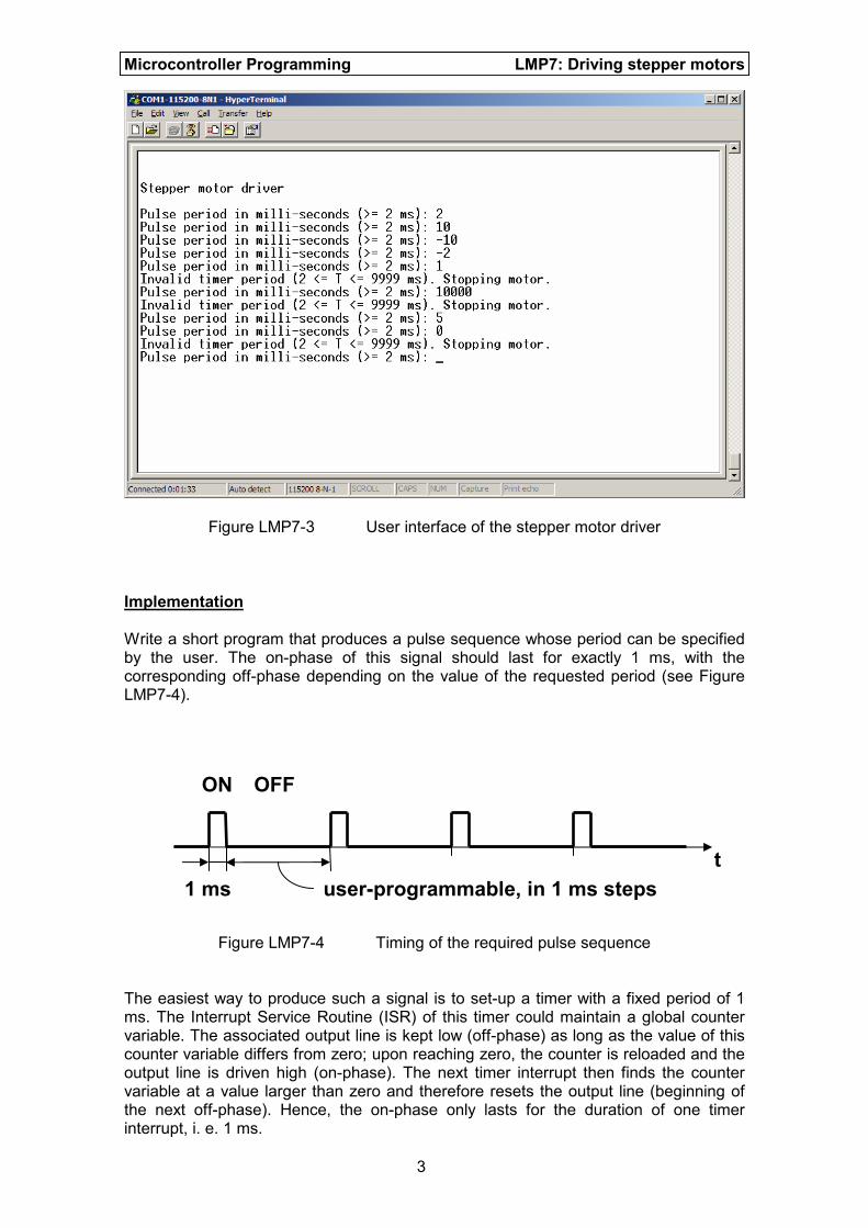
Figure LMP7-2 Circuit diagram of the stepper motor driver in Figure LMP7-1 The required software driver should make use of the communication routines developed in laboratory session LMP6. Choose a communication speed of 115200 bps, 8 data bits, no parity checking and one stop bit. The period of the driving pulse sequence should be programmable with a resolution of 1 ms and a maximum frequency of 500 Hz (T = 2 ms). Set-point requests below this threshold and above 10 seconds should result in an error message and make the motor stop. Figure LMP7-3 shows a screen shot of what the user interface may look like.
Microcontroller Programming LMP7: Driving stepper motors
3
Figure LMP7-3 User interface of the stepper motor driver
Implementation Write a short program that produces a pulse sequence whose period can be specified by the user. The on-phase of this signal should last for exactly 1 ms, with the corresponding off-phase depending on the value of the requested period (see Figure LMP7-4).
Figure LMP7-4 Timing of the required pulse sequence The easiest way to produce such a signal is to set-up a timer with a fixed period of 1 ms. The Interrupt Service Routine (ISR) of this timer could maintain a global counter variable. The associated output line is kept low (off-phase) as long as the value of this counter variable differs from zero; upon reaching zero, the counter is reloaded and the output line is driven high (on-phase). The next timer interrupt then finds the counter variable at a value larger than zero and therefore resets the output line (beginning of the next off-phase). Hence, the on-phase only lasts for the duration of one timer interrupt, i. e. 1 ms.
1 ms
ON OFF
t
user-programmable, in 1 ms steps
Microcontroller Programming LMP7: Driving stepper motors
4
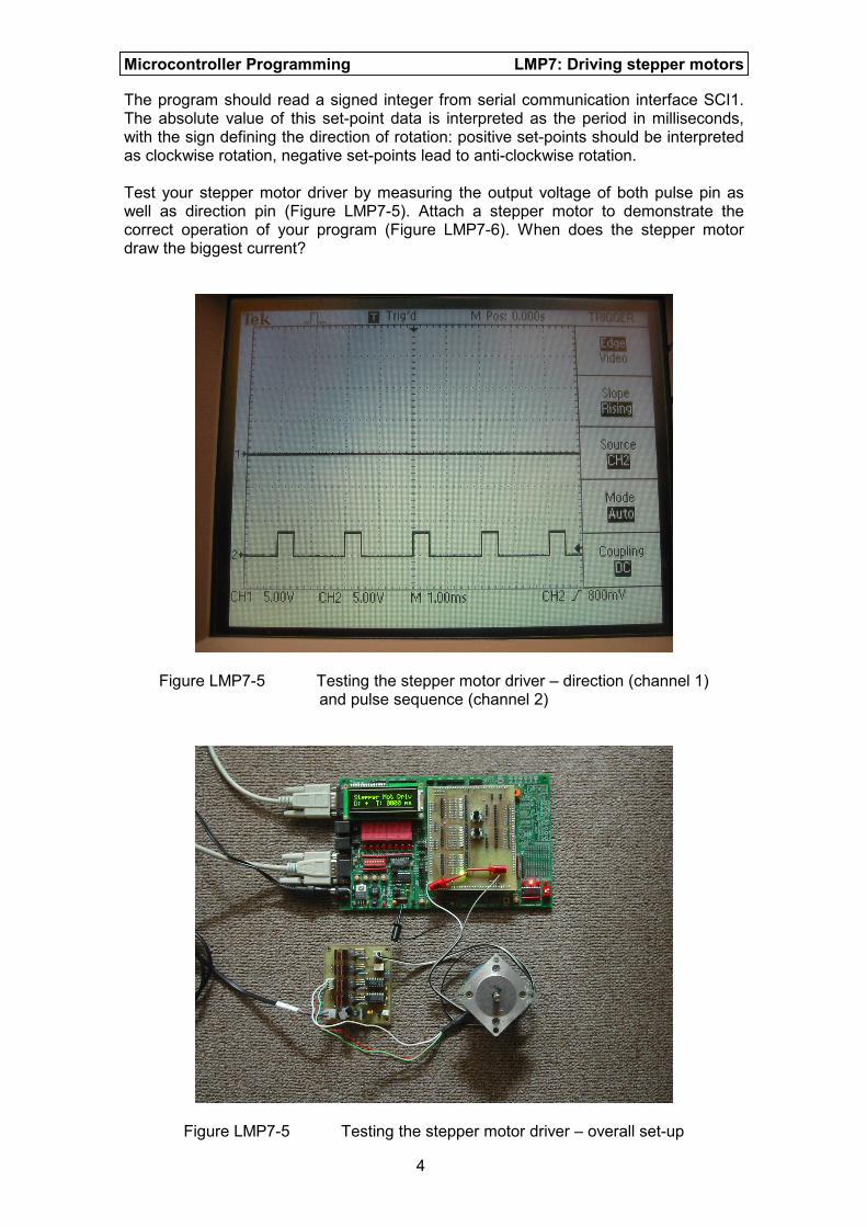
The program should read a signed integer from serial communication interface SCI1. The absolute value of this set-point data is interpreted as the period in milliseconds, with the sign defining the direction of rotation: positive set-points should be interpreted as clockwise rotation, negative set-points lead to anti-clockwise rotation. Test your stepper motor driver by measuring the output voltage of both pulse pin as well as direction pin (Figure LMP7-5). Attach a stepper motor to demonstrate the correct operation of your program (Figure LMP7-6). When does the stepper motor draw the biggest current?
Figure LMP7-5 Testing the stepper motor driver – direction (channel 1) and pulse sequence (channel 2)
Figure LMP7-5 Testing the stepper motor driver – overall set-up