Micro Controller Programs
63
1
Transcript of Micro Controller Programs

8/3/2019 Micro Controller Programs
http://slidepdf.com/reader/full/micro-controller-programs 1/63
1

8/3/2019 Micro Controller Programs
http://slidepdf.com/reader/full/micro-controller-programs 2/63
2

8/3/2019 Micro Controller Programs
http://slidepdf.com/reader/full/micro-controller-programs 3/63
CONTENTS
Ex. NO NAME OF THE EXPERIMENT PAGE NO
01.
02.
03.
04.
05.
06.
07.
08.
09.
10.
11.
12.
13.
01.02.
03
04.
05.
06.
SOFTWARE:
Introduction to Microcontroller kit
Addition , Subtraction
Multi byte addition
Multiplication of two numbers
Finding maximum value in an array
Arranging the given data in Ascending order
BCD to HEX Conversion
HEX to BCD Conversion
HEX to ASCII Conversion
ASCII to Binary Conversion
Square root of an Given data
Least Common Multiple
Greatest Common Divisor
HARDWARE:
Matrix KeyboardSeven segment displays.
LCD displays.
Traffic Light Control
Interfacing of stepper motor control.
Lift control.
5
9
13
15
17
19
23
25
29
31
33
35
37
4145
49
53
57
59
3

8/3/2019 Micro Controller Programs
http://slidepdf.com/reader/full/micro-controller-programs 4/63
SOFTWARE
Ex. No:1
4

8/3/2019 Micro Controller Programs
http://slidepdf.com/reader/full/micro-controller-programs 5/63
INTRODUCTION TO MICROCONTROLLER KIT
AIM:
To study about the microcontroller kit
APPARATUS REQUIRED:
Sl.No APPARATUS QUANTITY
1. Micro Controller Kit 1 No
THEORY:
A Single package microcontroller contains a central processing unit(CPU), semiconductor memory (RAM for data memory and ROM for program memory),a clock generator and input /output port capabilities processed in a single chip.
BLOCK DIAGRAM OF MICROCONTROLLER
FEATURES:
8051 is an 8 bit microcontroller
4096 bytes program memory on chip
128 bytes data memory on chip
Single supply +5v operation using HOMS technology 3 bidirectional I/O lines organized as four 8 bits ports.
ARCHITECTURE OF 8051 MICROCONTROLLER
5
ALU
ACCUMULATOR
REGISTER
PROGRAM COUNTER
STACK POINTER
INTERUPT CKT
TIMING AND CLOCK
CIRCUIT
INTERNAL ROM
INTERNAL RAM
TIMERS&COUNTERS
I/O PORT

8/3/2019 Micro Controller Programs
http://slidepdf.com/reader/full/micro-controller-programs 6/63
P0.0 – P0.7 P.2.0 – P2.7
PSEN
ALE
EA
RST
P1.0 – P1.7 P3.0 –P3.7
6
PORT 0 DRIVERS
PORT 2 DRIVERS
PORT 0LATCH
RAMRAM ADDR REGISTER
PORT2LATCH
FLASH
TMP
STACK POINTER
ACCBREGISTER
PSW
ALU
TMP1
INTERRUPT,SERIALPORT&TIMER BLOCKS
PROGAMADDRESREGISTER
BUFFER
PCINCREMENTER
PROGARMCOUNTER
DPTR
PORT1LATCH
PORT3LATCH
TIMINGAND INSTRUCTION
CONTROL REGISTER
PORT 1 DRIVERS PORT 3 DRIVERS
OSC
8/3/2019 Micro Controller Programs
http://slidepdf.com/reader/full/micro-controller-programs 7/63
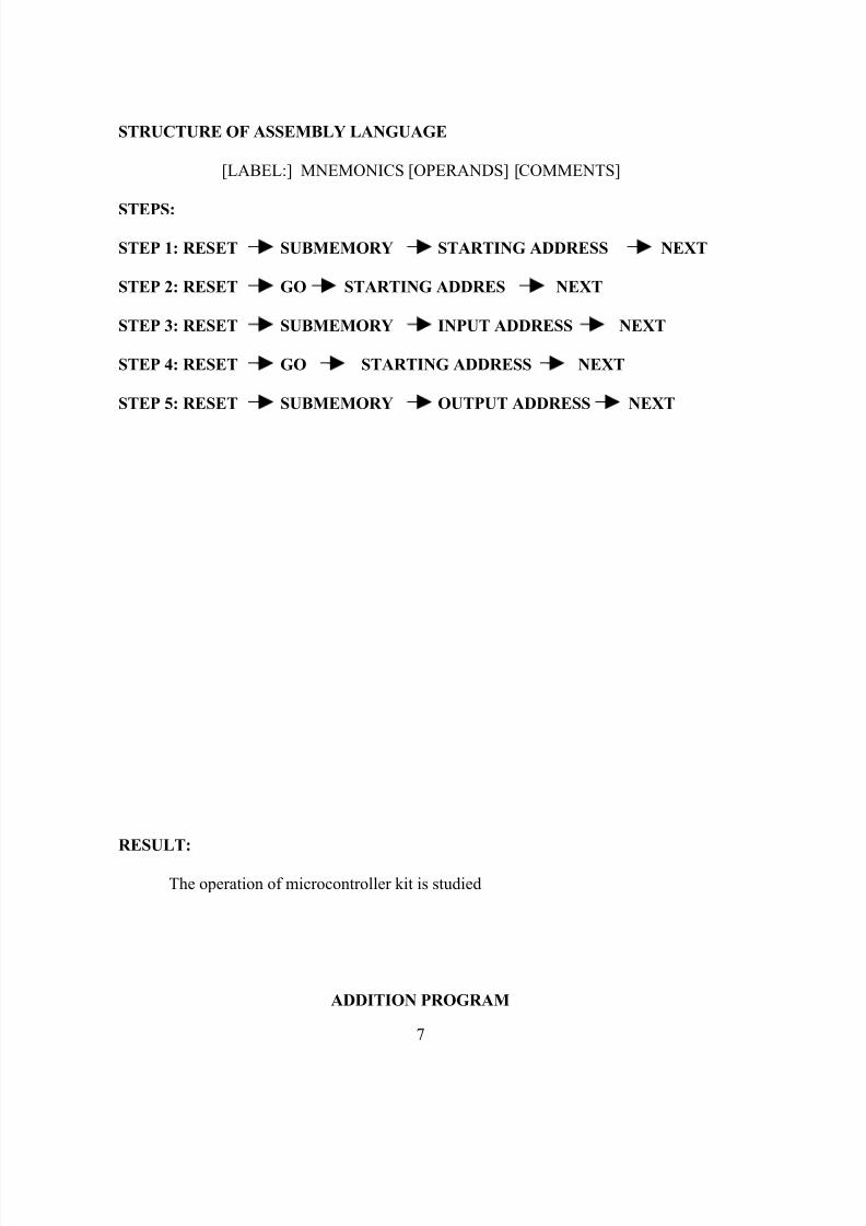
STRUCTURE OF ASSEMBLY LANGUAGE
[LABEL:] MNEMONICS [OPERANDS] [COMMENTS]
STEPS:
STEP 1: RESET SUBMEMORY STARTING ADDRESS NEXT
STEP 2: RESET GO STARTING ADDRES NEXT
STEP 3: RESET SUBMEMORY INPUT ADDRESS NEXT
STEP 4: RESET GO STARTING ADDRESS NEXT
STEP 5: RESET SUBMEMORY OUTPUT ADDRESS NEXT
RESULT:
The operation of microcontroller kit is studied
ADDITION PROGRAM
7

8/3/2019 Micro Controller Programs
http://slidepdf.com/reader/full/micro-controller-programs 8/63
MEMORYADDRESS
MNEMONICS HEX CODE COMMENTS
Opcode Operand
5000 MOV DPTR,#5101 90,51,01 Load the first data into the DPTR points.
5003 MOVX A, @DPTR E0 Move the data in the external RAM toAccumulator.
5004 MOV B,A F5,F0 Move the content of Accumulator to B( Direct)
5006 MOV DPTR,#5100 90,51,00 Load the second data into the DPTR points.
5009 MOVX A, @DPTR E0 Move the data in the external RAM toAccumulator.
500A CLR C C3 Clear carry
500B MOV R0,#00 78,00 Assign register for carry
500D ADD A,B 25,F0 Add 1st data and 2nd data500F JNC STORE 50,01 Check for carry
5011 INC R0 08 Increment the carry register
5012STORE:
MOV DPTR,#5200 90,52,00Load DPTR points with 16bit constant
5015 MOVX @DPTR, A F0 Move the lower byte of the result toexternal RAM.
5016 INC DPTR A3 Increment Data Pointer
5017 MOV A, R0 E8 Move the carry to Accumulator
5018 MOVX @DPTR,A F0 Move the higher byte of the result to
external RAM.5019 HALT: SJMP HALT 80,FE Short jump to the loop HALT.
8

8/3/2019 Micro Controller Programs
http://slidepdf.com/reader/full/micro-controller-programs 9/63
Ex.No.2A
ADDITION
AIM:To write a program for addition of two numbers.
APPARATUS REQUIRED:
SI.no APPARATUS QUANTITY
1. Micro controller kit 1 No
PROCEDURE:
1. Enter the hex code in the RAM Memory starting from the location 5000.
2. The program is executed after entering all the hex code.3. The inputs are given in the specified memory location.4. Execute the program.5. Store the result in the given location.
INPUT: OUTPUT:
5100: 1st data 5200: Result5101: 2nd data 5201: Carry
RESULT:
Thus the program for addition is executed and the output is noted.
9
8/3/2019 Micro Controller Programs
http://slidepdf.com/reader/full/micro-controller-programs 10/63
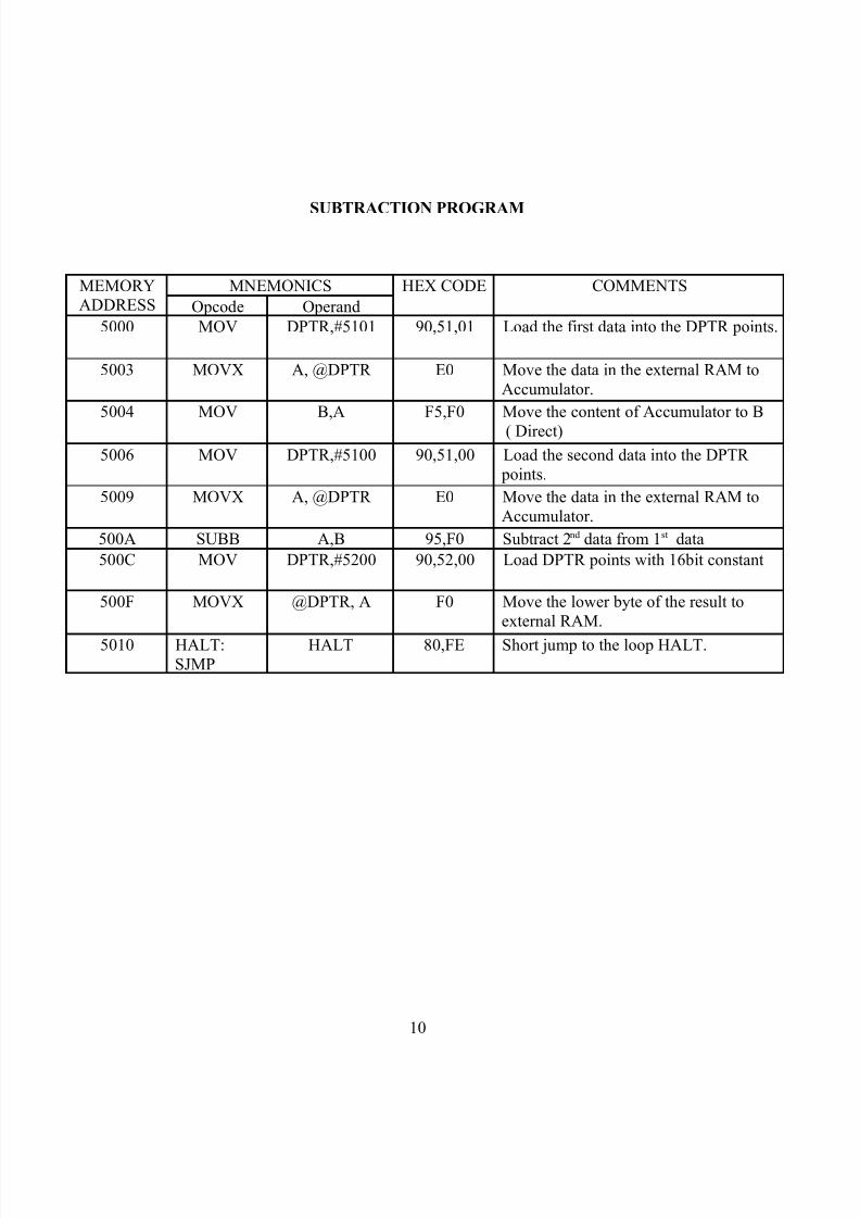
SUBTRACTION PROGRAM
MEMORYADDRESS
MNEMONICS HEX CODE COMMENTS
Opcode Operand
5000 MOV DPTR,#5101 90,51,01 Load the first data into the DPTR points.
5003 MOVX A, @DPTR E0 Move the data in the external RAM toAccumulator.
5004 MOV B,A F5,F0 Move the content of Accumulator to B
( Direct)
5006 MOV DPTR,#5100 90,51,00 Load the second data into the DPTR points.
5009 MOVX A, @DPTR E0 Move the data in the external RAM toAccumulator.
500A SUBB A,B 95,F0 Subtract 2nd data from 1st data
500C MOV DPTR,#5200 90,52,00 Load DPTR points with 16bit constant
500F MOVX @DPTR, A F0 Move the lower byte of the result toexternal RAM.
5010 HALT:SJMP
HALT 80,FE Short jump to the loop HALT.
10

8/3/2019 Micro Controller Programs
http://slidepdf.com/reader/full/micro-controller-programs 11/63
Ex.No.2B
SUBTRACTION
AIM:
To write a program for subtraction of two numbers.
APPARATUS REQUIRED:
SI.no APPARATUS QUANTITY
1. Micro controller kit 1 No
PROCEDURE:1. Enter the hex code in the RAM Memory starting from the location 5000.2. The program is executed after entering all the hex code.3. The inputs are given in the specified memory location.4. Execute the program.5. Store the result in the given location.
INPUT: OUTPUT:
5100: 1st data 5200: Result5101: 2nd data
RESULT:
Thus the program for subtraction is executed and the output is noted.
11

8/3/2019 Micro Controller Programs
http://slidepdf.com/reader/full/micro-controller-programs 12/63
MULTI BYTE ADDITION
MEMORYADDRESS
MNEMONICS HEXCODE COMMENTS
Opcode Operand
5000 MOV DPTR, #5100 90,51,00 Load the Data pointer with 16 bitconstant
5003 MOVX A, @DPTR E0 Move the LSB of the first Data presentin external RAM to A
5004 MOV R0, A F8 Move the content of A to R0
5005 INC DPTR A3 Increment Data pointer
5006 MOVX A, @DPTR E0 Move the MSB of the first Data present in external RAM to A
5007 MOV R1, A F9 Move the content of A to R1
5008 INC DPTR A3 Increment Data pointer
5009 MOVX A, @DPTR E0 Move the LSB of the Second Data
present in external RAM to A500A MOV R2, A FA Move the content of A to R2
500B INC DPTR A3 Increment Data pointer
500C MOVX A, @DPTR E0 Move the MSB of the Second Data present in external RAM to A
500D MOV R3, A FB Move the content of A to R3
500E MOV A, R0 E8 Move the content of R0 to A
500F MOV R4, #00 7C,00 Clear the register R4 to store carry
5011 ADD A, R2 2A Add the LSB’s of the data
5012 INC DPTR A3 Increment Data pointer
5013 MOVX @DPTR, A F0 Store the LSB result in the givenlocation.
5014 MOV A, R1 E9 Move the content of R1 to A
5015 ADDC A, R3 3B Add the content of R3 to A with carry
5016 JNC LOOP 50,02 Jump to LOOP if carry flag is not setotherwise increment R4
5018 INC R4 0C Increment R4 for carry
5019 INC DPTR A3 Increment Data pointer
501A MOVX @DPTR, A F0 Store the MSB result in the givenlocation.
501B MOV A, R4 EC Move the carry bit to A
501C INC DPTR A3 Increment Data pointer 501D MOVX @DPTR, A F0 Store the Carry in the given location.
501EHALT:SJMP HALT 80,FE Short jump to loop HALT
12

8/3/2019 Micro Controller Programs
http://slidepdf.com/reader/full/micro-controller-programs 13/63
Ex.No:3
MULTI BYTE ADDITION
AIM:
To write a program for Multi byte addition.
APPARATUS REQUIRED:
SI.no APPARATUS QUANTITY
1. Micro controller kit
1 No
PROCEDURE:
1. Enter the hex code in the RAM Memory starting from the location5000
2. The program is executed after entering all the hex code.3. The inputs are given in the specified memory location.4. Execute the program.5. Store the result in the given location.
INPUT: OUTPUT:
5100: LSB1 5104: LSB of the result5101: MSB1 5105: MSB of the result5102: LSB2 5106: Carry5103: MSB2
RESULT:
Thus the program for Multi byte addition is executed and the output is noted.
13

8/3/2019 Micro Controller Programs
http://slidepdf.com/reader/full/micro-controller-programs 14/63
MULTIPLICATION PROGRAM
14
MEMORY
ADDRESS
MNEMONICS HEX CODE COMMENTS
Opcode Operand5000 MOV DPTR,#5100 90,51,00 Load the first data into the DPTR
points.
5003 MOVX A, @DPTR E0 Move the data in the external RAMto Accumulator.
5004 INC DPTR A3 Increment Data Pointer
5005 MOV B,A F5,F0 Move the content of Accumulator to B ( Direct)
5007 MOVX A, @DPTR E0 Move the second data in theexternal RAM to Accumulator.
5008 MUL AB A4 Multiply the content of accumulator
with B register.5009 MOV DPTR,#5200 90,52,00 Load DPTR points with 16bit
constant
500C MOVX @DPTR, A F0 Move the lower byte of the result toexternal RAM.
500D INC DPTR A3 Increment Data Pointer
500E MOV A, B E5,F0 Move the content of B register toAccumulator
5010 MOVX @DPTR,A F0 Move the higher byte of the resultto external RAM.
5011 HALT:
SJMP
HALT 80,FE Short jump to the loop HALT.

8/3/2019 Micro Controller Programs
http://slidepdf.com/reader/full/micro-controller-programs 15/63
Ex.No.4
MULTIPLICATION
AIM:
To write a program for multiplication of two numbers.
APPARATUS REQUIRED:
SI.no APPARATUS QUANTITY
1. Micro controller kit 1 No
PROCEDURE:
1. Enter the hex code in the RAM Memory starting from the location 5000.2 .The program is executed after entering all the hex code.3. The inputs are given in the specified memory location.
4. Execute the program.5. Store the result in the given location.
INPUT: OUTPUT:
5100: Multiplicand 5200: Lower byte of the result
5101: Multiplier 5201: Higher byte of the result
RESULT:
Thus the program for multiplication is executed and the output is noted.
15

8/3/2019 Micro Controller Programs
http://slidepdf.com/reader/full/micro-controller-programs 16/63
FINDING MAXIMUM VALUE PROGRAM
MEMORYADDRESS
MNEMONICS HEXCODE COMMENTS
Opcode Operand
5000 CLR C C3 Clear Carry
5001 MOV DPTR,#5100 90,51,00 Load the address in Dptr
5004 MOVX A,@DPTR E0 Move the external ram to Acc
5005 MOV R0,A F8 Move the Acc to R0 Reg
5006 MOV 40H,#00H 75,40,00 Move 00 to 40H address
5009 REPEAT:INC DPTR A3 Increment Data Pointer
500A MOVX A,@DPTR E0 Content of DPTR is moved to acc
500B CJNE A,40,STEP3 B5,40,0A Compare the Acc with 40H address
500E STEP2:DJNZ R0,REPEAT D8,F9 Decrement R0 and jump to relativeaddress
5010 MOV DPTR,#5500 90,55,00 Load DPTR with 5500
5013 MOV A,40H E5,40 Move the 40H address to Acc
5015 MOVX @DPTR,A F0 Move the result to given location
5016 HLT:SJMP HLT 80,FE Be in a loop HLT
5018 STEP3:JC STEP1 40,02 If carry present go to step1
501A MOV 40H,A F5,40 Move the content of acc to 40haddress
501C STEP1:SJMP STEP2 80,F0 Jump to step2
16

8/3/2019 Micro Controller Programs
http://slidepdf.com/reader/full/micro-controller-programs 17/63
Ex.No:5
FINDING MAXIMUM VALUE
AIM:
To write a program for finding the maximum value in an array.
APPARATUS REQUIRED:
SI.no APPARATUS QUANTITY
1. Micro controller kit
1 No
PROCEDURE:
1. Enter the hex code in the RAM Memory starting from the location5000.
2. Specify the length of the array in the program.3. The inputs are given in the specified memory location.
4. Execute the program.5. Store the result in the given memory location.
INPUT: OUTPUT:
5100: Count - 1 (Length of array) 5200: Maximum value5101:
RESULT:Thus the program for finding the maximum value in an array is executed and the
output is noted.
17
8/3/2019 Micro Controller Programs
http://slidepdf.com/reader/full/micro-controller-programs 18/63
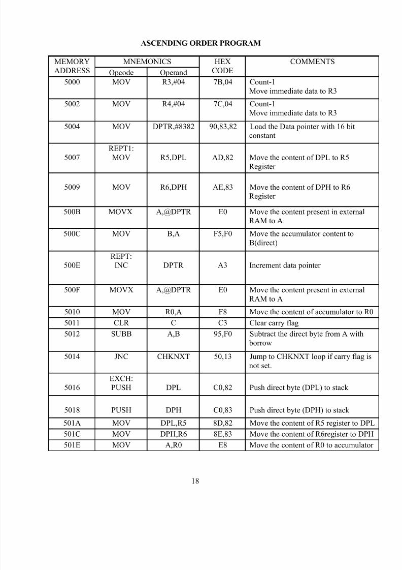
ASCENDING ORDER PROGRAM
MEMORYADDRESS
MNEMONICS HEXCODE
COMMENTS
Opcode Operand
5000 MOV R3,#04 7B,04 Count-1Move immediate data to R3
5002 MOV R4,#04 7C,04 Count-1Move immediate data to R3
5004 MOV DPTR,#8382 90,83,82 Load the Data pointer with 16 bitconstant
5007REPT1:MOV R5,DPL AD,82 Move the content of DPL to R5
Register
5009 MOV R6,DPH AE,83 Move the content of DPH to R6
Register 500B MOVX A,@DPTR E0 Move the content present in external
RAM to A
500C MOV B,A F5,F0 Move the accumulator content toB(direct)
500EREPT:
INC DPTR A3 Increment data pointer
500F MOVX A,@DPTR E0 Move the content present in external
RAM to A5010 MOV R0,A F8 Move the content of accumulator to R0
5011 CLR C C3 Clear carry flag
5012 SUBB A,B 95,F0 Subtract the direct byte from A with borrow
5014 JNC CHKNXT 50,13 Jump to CHKNXT loop if carry flag isnot set.
5016EXCH:PUSH DPL C0,82 Push direct byte (DPL) to stack
5018 PUSH DPH C0,83 Push direct byte (DPH) to stack
501A MOV DPL,R5 8D,82 Move the content of R5 register to DPL
501C MOV DPH,R6 8E,83 Move the content of R6register to DPH
501E MOV A,R0 E8 Move the content of R0 to accumulator
18

8/3/2019 Micro Controller Programs
http://slidepdf.com/reader/full/micro-controller-programs 19/63
Ex.No:6 ASCENDING ORDER
AIM:
To write a program for Sorting of 8 bit data’s in ascending order.
APPARATUS REQUIRED:
SI.no APPARATUS QUANTITY
1. Micro controller kit
1 No
PROCEDURE:
1. Enter the hex code in the RAM Memory starting from the location5000.
2. Specify the length of the array in the program.3. The inputs are given in the specified memory location.
4. Execute the program. INPUT: OUTPUT:
8382: 8382:8383: 8383:8384: 8384:8385: 8385:8386: 8386:
19

8/3/2019 Micro Controller Programs
http://slidepdf.com/reader/full/micro-controller-programs 20/63
501F MOVX @DPTR,A F0 Move A to external RAM
5020 POP DPH D0,83 POP the direct byte (DPH) from stack
5022 POP DPL D0,82 POP the direct byte (DPL) from stack
5024 MOV A,B E5,F0 Move the direct byte to accumulator
5026 MOVX @DPTR,A F0 Move A to external RAM
5027 MOV B,R0 88,F0 Move the content of R0 to B register.
5029CHKNXT:
DJNZ R5,REPT DB,E3Decrement the content of R5 register and jump to loop REPT if not zero
502B DEC R4 1C Decrement R4 register
502C MOV A,R4 EC Move the content of R4 to accumulator
502D MOV R3,A FB Move the content of accumulator to R3
502E INC R4 0C Increment R4 register
502F MOV DPL,R5 8D,82 Move the content of R5 register to DPL
5031 MOV DPH,R6 8E,83 Move the content of R6 register to DPH
5033 INC DPTR A3 Increment data pointer
5034 DJNZ R4,REPT1 DC,D1Decrement the content of R4 register and jump to loop REPT1 if not zero
5036 HALT:SJMP HALT 80,FE Short jump to loop HALT
20
8/3/2019 Micro Controller Programs
http://slidepdf.com/reader/full/micro-controller-programs 21/63
RESULT:
Thus the program for sorting of 8 bit data’s in ascending order is executed andthe output is noted.
BCD TO HEX CONVERSION
21

8/3/2019 Micro Controller Programs
http://slidepdf.com/reader/full/micro-controller-programs 22/63
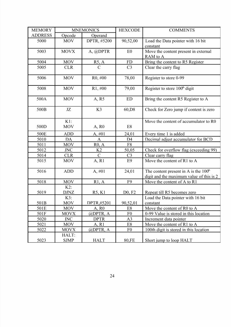
MEMORYADDRESS
MNEMONICS HEXCODE COMMENTS
Opcode Operand
5000 MOV DPTR,#5200 90,52,00 Load the Data pointer with 16 bitconstant
5003 MOVX A,@DPTR E0 Move the content present inexternal RAM to A
5004 MOV R5,A FD Bring the content to R5 Register 5005 ANL A,#F0 54,F0 Separate the 10th digit. Mask the
4 bit
5007 RL A 23 Bring the MSB to LSB by rotateinstruction
5008 RL A 23
5009 RL A 23
500A RL A 23 MSB is changed to LSB
500B MOV R1, A F9 Store the 10th digit in R1
500C MOV A, R5 ED From original number separate1’s digit
500D ANL A, #0F 54,0F Separate the 1’s digit.
500F MOV R2, A F8 Store in R2 register
5010 MOV A, R1 E9 Move the content of R1 to A
5011 MOV FO, #0A 75,F0, 0A
5014 MUL AB A4 Multiply 10’s digit with 0A
5015 ADD A, R2 2A Add unit digit to the multipliednumbers
5016 INC DPTR A3 Increment data pointer 5017 MOVX @DPTR, A F0 Result is stored in this location
5018HALT:SJMP HALT 80,FE Short jump to loop HALT
22

8/3/2019 Micro Controller Programs
http://slidepdf.com/reader/full/micro-controller-programs 23/63
Ex.No:7 BCD TO HEX CONVERSION
AIM:
To write a program to convert the given of BCD value to its equivalentHexadecimal value.
APPARATUS REQUIRED:
SI.no APPARATUS QUANTITY
1. Micro controller kit
1 No
PROCEDURE:
1. Enter the hex code in the RAM Memory starting from the location5000.
2. The program is executed after entering all the hex code.3. The inputs are given in the specified memory location.4. Execute the program.
5. Store the result in the given location.
INPUT: OUTPUT:
5200: 5201:
RESULT:
Thus the program for conversion of BCD number to Hexadecimal number isexecuted and the output is noted.
HEX TO BCD CONVERSION
23
8/3/2019 Micro Controller Programs
http://slidepdf.com/reader/full/micro-controller-programs 24/63
MEMORYADDRESS
MNEMONICS HEXCODE COMMENTS
Opcode Operand
5000 MOV DPTR, #5200 90,52,00 Load the Data pointer with 16 bitconstant
5003 MOVX A, @DPTR E0 Move the content present in external
RAM to A5004 MOV R5, A FD Bring the content to R5 Register
5005 CLR C C3 Clear the carry flag
5006 MOV R0, #00 78,00 Register to store 0-99
5008 MOV R1, #00 79,00 Register to store 100th digit
500A MOV A, R5 ED Bring the content R5 Register to A
500B JZ K3 60,D8 Check for Zero jump if content is zero
500DK1:
MOV A, R0 E8Move the content of accumulator to R0
500E ADD A, #01 24,01 Every time 1 is added
5010 DA A D4 Decimal adjust accumulator for BCD
5011 MOV R0, A F8
5012 JNC K2 50,05 Check for overflow flag (exceeding 99)
5014 CLR C C3 Clear carry flag
5015 MOV A, R1 E9 Move the content of R1 to A
5016 ADD A, #01 24,01 The content present in A is the 100th
digit and the maximum value of this is 2
5018 MOV R1, A F9 Move the content of A to R1
5019K2:
DJNZ R5, K1 D0, F2 Repeat till R5 becomes zero
501BK3:
MOV DPTR,#5201 90,52,01Load the Data pointer with 16 bitconstant
501E MOV A, R0 E8 Move the content of R0 to A
501F MOVX @DPTR, A F0 0-99 Value is stored in this location
5020 INC DPTR A3 Increment data pointer
5021 MOV A, R1 E8 Move the content of R1 to A
5022 MOVX @DPTR, A F0 100th digit is stored in this location
5023HALT:SJMP HALT 80,FE Short jump to loop HALT
24

8/3/2019 Micro Controller Programs
http://slidepdf.com/reader/full/micro-controller-programs 25/63
Ex.No:8 HEX TO BCD CONVERSION
AIM:
To write a program to convert the given Hexadecimal value to its equivalent BCDvalue.
APPARATUS REQUIRED:
SI.no APPARATUS QUANTITY
1. Micro controller kit
1 No
PROCEDURE:
1. Enter the hex code in the RAM Memory starting from the location5000.
2. The program is executed after entering all the hex code.3. The inputs are given in the specified memory location.4. Execute the program.
5. Store the result in the given location.
INPUT: OUTPUT:
5200: HEX Data 5201: Lower byte of theresult
5202: Higher byte of theresult
RESULT:
Thus the program for conversion of Hexadecimal number to BCD number isexecuted and the output is noted.
25

8/3/2019 Micro Controller Programs
http://slidepdf.com/reader/full/micro-controller-programs 26/63
HEX TO ASCII CONVERSION
MEMORYADDRESS
MNEMONICS HEXCODE COMMENTS
Opcode Operand
5000 MOV DPTR, #6000 90,60,00 Load the Data pointer with 16 bit const
5003 MOVX A, @DPTR E0 Move the content present in external RAto A
5004 MOV 50H,A F5, 50 Bring the content A to memory location50H
5006 MOV R0, #50H 78,50 Move the immediate data to R0 register
5008 MOV A, @R0 E6 Move the content to A
5009 MOV R2, A FA Move the content of A to R2
500A ANL A, #0F 54,0F Mask the MSB
500C MOV R1, A F9 Move the content of A to R1
500D CLR C C3 Clear the carry flag
500E SUBB A, #09 94,09 Subtract 09 from the accumulator conte
5010 JC LOOP 40,07 Jump to LOOP if carry flag is set
5012 JZ LOOP 60,05 Jump to LOOP if the content of A is zer
5014 MOV A, R1 E9 Move the content of R1 to A
5015 ADD A, #37 24,37 Add 37 to the accumulator content
5017 SJMP LOOP2 80,03 Short jump to LOOP2
5019LOOP:MOV A, R1 E9 Move the content of R1 to A
5015 ADD A, #30 24,30 Add 30 to the content of A
501CLOOP2:
INC R0 08 Increment R0
501D INC R0 08 Increment R0
501E MOV DPTR, #6002 90,60,02 Load the Data pointer with 16 bit const
5021 MOV @R0, A F6 Move the content of A to the locationspecified in R0
5022 MOVX @DPTR, A F0 Move the content of A to the gilocation
5023 MOV A, R2 EAMove the content of R2 to the given location
5024 RR A 03 Rotate the content of accumulator right
5025 RR A 03 Rotate the content of accumulator right
5026 RR A 03 Rotate the content of accumulator right
5027 RR A 03 Rotate the content of accumulator right
5028 ANL A, #0F 54,0F AND the content of A with 0F
502A MOV R3, A FB Move the content of A to R3
502B CLR C C3 Clear carry flag
26

8/3/2019 Micro Controller Programs
http://slidepdf.com/reader/full/micro-controller-programs 27/63
502C SUBB A, #09 94,09 Subtract 09 from the accumulator conte
502E JC LOOP1 40,07 Jump to LOOP1 if carry flag is set
5030 JZ LOOP1 60,05 Jump to LOOP1 if the content of A is z
5032 MOV A, R3 EB Move the content of R3 to A
5033 ADD A, #37 24,37 Add 37 to the accumulator content
5035 SJMP LOOP3 80,03 Short jump to LOOP3
5037LOOP1:
MOV A, R3 EBMove the content of R3 to A
5038 ADD A, #30 24,30 Add 30to the accumulator content
503ALOOP3:
DEC R0 18 Decrement R0
503B MOV DPTR, #6001 90,60,01 Load the Data pointer with 16 bit const
503E MOV @R0, A F6 Move the content of A to the locationspecified in R0
503F MOVX @DPTR, A F0 Move the content of A to the givenlocation
5040HALT:SJMP HALT 80,FE Short jump to loop HALT
27

8/3/2019 Micro Controller Programs
http://slidepdf.com/reader/full/micro-controller-programs 28/63
Ex.No:9
HEX TO ASCII CONVERSION
28
8/3/2019 Micro Controller Programs
http://slidepdf.com/reader/full/micro-controller-programs 29/63
AIM:
To write a program to convert the given Hexadecimal value to its equivalent ASCII.
APPARATUS REQUIRED:
SI.no APPARATUS QUANTITY
1. Micro controller kit
1 No
PROCEDURE:
1. Enter the hex code in the RAM Memory starting from the location 5000.2. The program is executed after entering all the hex code.3. The inputs are given in the specified memory location.4. Execute the program.5. Store the result in the given location.
INPUT: OUTPUT:
6000: 6001:6002:
RESULT:
Thus the program for conversion of Hexadecimal number to ASCII is executedand the output is noted.
ASCII TO BINARY CONVERSION
29

8/3/2019 Micro Controller Programs
http://slidepdf.com/reader/full/micro-controller-programs 30/63
MEMORYADDRESS
MNEMONICS HEXCODE COMMENTS
Opcode Operand
5000 MOV DPTR, #5100 90,51,00 Load the Data pointer with 16 bit constan
5003 MOVX A,@DPTR E0 Move the data in the external ram toAccumulator
5004 CLR C C3 Clear carry
5005 SUBB A,#30H 94,30 Subtract 30 From Accumulator WithBorrow
5007 MOV 40H,#OA 75,40,0A Move the 0A to internal RAM to 40H
500A CJNE A,40,NXT B5,0,00 Compare the acc content is less than 0A
500D NXT:JC CODE 40,02 If yes go to CODE label
500F SUBB A,#07H 94,07 Else subtract 07 from acc content
5011 CODE:INC DPTR A3 Increment Data pointer
5012 MOVX @DPTR,A F0 Store the result in 5101
5013 HLT:SJMP HLT 80,FE Be in a loop
Ex.No:10
30

8/3/2019 Micro Controller Programs
http://slidepdf.com/reader/full/micro-controller-programs 31/63
ASCII TO BINARY CONVERSION
AIM:
To write a program for ASCII TO BINARY CONVERSION
APPARATUS REQUIRED:
SI.no APPARATUS QUANTITY
1. Micro controller kit
1 No
PROCEDURE:
1. Enter the hex code in the RAM Memory starting from the location 5000.2. The program is executed after entering all the hex code.3. The inputs are given in the specified memory location.4. Execute the program.5. Store the result in the given location.
INPUT: OUTPUT:
5100: 5101:
RESULT:
Thus the program for conversion of ASCII TO BINARY CONVERSIONis executed and the output is noted.
SQUARE ROOT OF A GIVEN NUMBER
MNEMONICS HEXCODE COMMENTS
31

8/3/2019 Micro Controller Programs
http://slidepdf.com/reader/full/micro-controller-programs 32/63
MEMORYADDRESS
OPCODE OPERAND
5000 MOV DPTR,#5100 90,51,00 Load the data pointer with 16 bit constan
5003 MOVX A,@DPTR E0 Move the content present in external ramAcc.
5004 MOV R0,#01H 78,01 Set R0 for counter
5006 MOV R1,#01H 79,01 Set R1 for Odd number
5008 NXTSUB:CLR
C C3 Clear carry
5009 SUBB A,R1 99 Subtract odd number from Acc
500A JZ OVER 60,07 Jump to over if A=0
500C JC ERROR 40,0A Jump to ERROR if carry present
500E INC R0 08 Increment R0 Reg
500F INC R1 09 Increment R1 Reg
5010 INC R1 09 Increment R1 Reg
5011 SJMP NXTSUB 80,F5 Repeat subtraction5013 OVER:
MOVA,R0 E8 Move result to Acc
5014 INC DPTR A3 Increment DataPointer
5015 MOVX @DPTR,A F0 Move the Acc content to given location
5016 HERE:SJMP
HERE 80,FE Be in loop here
5018 ERROR:MOV
A,#FFH 74,FF Store ERROR code FFH
501A INC DPTR A3 Increment DataPointer
501B MOVX @DPTR,A F0 Move the perfect square number to givenlocation
501C AGAIN:SJMP
AGAIN 80,FE Be in loop AGAIN
32
8/3/2019 Micro Controller Programs
http://slidepdf.com/reader/full/micro-controller-programs 33/63
Ex.No:11
SQUARE ROOT OF A GIVEN NUMBER
AIM:
To write a program for SQUARE ROOT OF A GIVEN NUMBER
APPARATUS REQUIRED:
SI.no APPARATUS QUANTITY
1. Micro controller kit
1 No
PROCEDURE:
1. Enter the hex code in the RAM Memory starting from the location 5000.2. The program is executed after entering all the hex code.
3. The inputs are given in the specified memory location.4. Execute the program.5. Store the result in the given location.
INPUT: OUTPUT:
5100: 5101:
RESULT:
Thus the program for SQUARE ROOT OF A GIVEN NUMBER executed
and the output is noted.
33

8/3/2019 Micro Controller Programs
http://slidepdf.com/reader/full/micro-controller-programs 34/63
LEAST COMMON MULTIPLE
MEMORYADDRESS
MNEMONICS HEX CODE COMMENTS
Opcode Operand
5000 MOV DPTR,#5100 90,51,00 Load The First Data Into The DPTR Poin
5003 MOVX A,@DPTR E0 Move the data in the external ram toAccumulator
5004 MOV R0,A F8 Save the second number In R0 Register
5005 INC DPTR A3 Increment data pointer
5006 MOVX A,@DPTR EO Move the content of external RAM toAccumulator
5007 MOV R1,A F9 Save 1st number in R1 Register
5008 NXT DIV:MOV
R2,A FA Save 1st number in R2 Register
5009 MOV B,R0 88,F0 Save the 2nd number in B Register
500B DIV AB 84 Divide the 1st & 2nd number
500C MOV A,B E5,F0 Move reminder to Accumulator
500E MOV 40H,#00 75,40,00 Move 00 to 40H
5011 CJNE A,40,NXT B5,40,05 check reminder is 0; if not jump to NXT
5014 MOV A,R2 EA Move LCM to Accumulator
5015 INC DPTR A3 Increment data pointer
5016 MOVX @DPTR,A F0 Move the content of A to 5102
5017 HERE:SJMP
HERE 80,FE Be in a loop
5019 NXT:MOV A,R2 EA Move the content of R2 to Accumulator
501A ADD A,R0 29 Add 1st number to 1st number
501B SJMP NXTDIV 80,EB Go and perform next division
34

8/3/2019 Micro Controller Programs
http://slidepdf.com/reader/full/micro-controller-programs 35/63
Ex.No:12
LEAST COMMON MULTIPLE
AIM:
To write a program for LEAST COMMON MULTIPLE
APPARATUS REQUIRED:
SI.no APPARATUS QUANTITY
1. Micro controller kit
1 No
PROCEDURE:
1. Enter the hex code in the RAM Memory starting from the location 5000.2. The program is executed after entering all the hex code.3. The inputs are given in the specified memory location.4. Execute the program.
5. Store the result in the given location.
INPUT: OUTPUT:
5100: 5101:
RESULT:
Thus the program for LEAST COMMON MULTIPLEis executed and the output is noted.
35

8/3/2019 Micro Controller Programs
http://slidepdf.com/reader/full/micro-controller-programs 36/63

8/3/2019 Micro Controller Programs
http://slidepdf.com/reader/full/micro-controller-programs 37/63
Ex.No:13
GREATEST COMMON DIVISOR
AIM:
To write a program for GREATEST COMMON DIVISOR
APPARATUS REQUIRED:
SI.no APPARATUS QUANTITY
1. Micro controller kit
1 No
PROCEDURE:
1. Enter the hex code in the RAM Memory starting from the location 5000.2. The program is executed after entering all the hex code.3. The inputs are given in the specified memory location.
4. Execute the program.5. Store the result in the given location.
INPUT: OUTPUT:
5100: 5102:5101:
RESULT:
Thus the program for GREATEST COMMON DIVISOR is executed and the output is noted.
37

8/3/2019 Micro Controller Programs
http://slidepdf.com/reader/full/micro-controller-programs 38/63
38

8/3/2019 Micro Controller Programs
http://slidepdf.com/reader/full/micro-controller-programs 39/63
HARDWARE
39

8/3/2019 Micro Controller Programs
http://slidepdf.com/reader/full/micro-controller-programs 40/63
40

8/3/2019 Micro Controller Programs
http://slidepdf.com/reader/full/micro-controller-programs 41/63
MEMORY MNEMONICS HEXCODE
41

8/3/2019 Micro Controller Programs
http://slidepdf.com/reader/full/micro-controller-programs 42/63
ADDRESS OPCODE OPERAND
4100 MOV DPTR,#FF0FH 90,FF,0F
4103 MOV A,#82H 74,82
4105 MOVX @DPTR,A F0
4106 START:MOV A,#00H 74,00
4108 MOV DPTR,#FF0CH 90,FF,0C
410B MOVX @DPTR,A F0
410C MOV DPTR,#FF0DH 90,FF,0D
410F MOVX A,@DPTR E0
4110 ANL A,#0FH 54,0F
4112 CJNE A,#0FH,CONT B4,0F,03
4115 LJMP START 02,41,06
4118 CONT:LCALL
GETDAT 12,41,1E
411B LJMP START 02,41,06411E GETDAT:MOV
R2,#51H 7A,51
4120 MOV R3,#00H 7B,00
4122 MOV R4,#52H 7C,52
4124 MOV R5,#00H 7D,00
4126 MOV A,#0EH 74,0E
4128 LCALL FIND1 12,41,3B
412B MOV A,#0DH 74,0D
412D LCALL FIND1 12,41,3B
4130 MOV A,#0BH 74,0B4132 LCALL FIND1 12,41,3B
4135 MOV A,#07H 74,07
4137 LCALL FIND1 12,41,3B
413A RET 22
413B FIND1:MOV DPTR,#FF0CH 90,FF,0C
413E MOVX @DPTR,A F0
413F MOV DPTR,#FF0DH 90,FF,0D
4142 MOVX A,@DPTR E0
4143 ANL A,#0FH 54,0F
4145 MOV R6,A FE4146 MOV R7,#04H 7F,04
4148 FFN2:MOV DPH,R4 8C,83
414A MOV DPL,R5 8D,82
414C MOVX A,@DPTR E0
42

8/3/2019 Micro Controller Programs
http://slidepdf.com/reader/full/micro-controller-programs 43/63
Ex.No:1
MATRIX KEYBOARD
AIM:
To write a program to interface matrix keyboard with 8051 microcontroller. APPARATUS REQUIRED:
SI.no APPARATUS QUANTITY
1. Micro controller kit
1 No
2. Keyboard Interface card 1 No
PROCEDURE:1. Connect the keyboard interface card to Micro controller 2. Enter the hex code in the RAM Memory starting from the location
41003. Execute the program.4. Display will be blank in the card.5. Now press any key.6. Output will be observed in LCD of 8051 by using matrix keyboard
414D MOV DPL,R6 8E,82
414F CJNE A,DPL,FFN3 B5,82,04
4152 LCALL STOREDAT 12,41,5F
43

8/3/2019 Micro Controller Programs
http://slidepdf.com/reader/full/micro-controller-programs 44/63
4155 RET 22
4156 FFN3:INC R3 0B
4157 INC R5 0D
4158 DJNZ R7,FFN2 DF,EE
415A MOV R4,#52H 7C,52
415C MOV R5,#00H 7D,00
415E RET 22
415F STOREDAT:LCALL
BSYCHK 12,41,93
4162 MOV DPL,#DEN 90,FF,04
4165 MOV A,#38H 74,38
4167 MOVX @DPTR,A F0
4168 LCALL BSYCHK 12,41,93
416B MOV A,#01H 74,01
416D MOVX @DPTR,A F0
416E LCALL BSYCHK 12,51,93
4171 MOV A,#06H 74,06
4173 MOVX @DPTR,A F0
4174 LCALL BSYCHK 12,41,93
4177 MOV A,#0FH 74,0F
4179 MOVX @DPTR,A F0
417A LCALL BSYCHK 12,41,93
417D MOV A,#80H 74,80
417F MOVX @DPTR,A F0
4180 MOV DPH,R2 8A,83
4182 MOV DPL,R3 8B,82
4184 MORE:LCALL
BSYCHK 12,41,93
4187 MOV A,#01H 74,01
4189 MOV P2,#IOHIGH 75,A0,FF
418C MOVX @R0,A F2
418D MOVX A,@DPTR E0
418E MOV P2,#IOHIGH 75,A0,FF
4191 MOVX @R1,A F3
4192 RET 22
4193 BSYCHK:MO
V
R1,#DENL 79,04
4195 MOV R0,#LATCHL 78,08
4197 MOV P2,#IOHIGH 75,A0,FF
419A MOV A,#02H 74,02
419C MOVX @R0,A F2
419D BSY:MOV P2,#IOHIGH 75,A0,FF
41A0 MOVX A,@R1 E3
44

8/3/2019 Micro Controller Programs
http://slidepdf.com/reader/full/micro-controller-programs 45/63
41A1 ANL A,#80H 54,80
41A3 JNZ BSY 70,FA
41A5 MOV P2,#IOHIGH 75,A0,FF
41A8 MOV A,#00H 74,00
41AA MOVX @R0,A F2
41AB RET 22
INPUTADDRESS DATA TO BE STORED
5100 30H,31H,32H,33H
5104 34H,35H,36H,37H
5108 38H,39H,41H,42H
510C 43H,44H,45H,46H
5200 0EH,0DH,0BH,07H
RESULT:
Thus the program for interfacing matrix keyboard with 8051 microcontroller isexecuted and output is observed in LCD of 8051 by using matrix keyboard.
SEVEN SEGMENT DISPLAY
45

8/3/2019 Micro Controller Programs
http://slidepdf.com/reader/full/micro-controller-programs 46/63
ORG 4100HCNTRL EQU FF0FHPORTA EQU FF0CHPORTB EQU FF0DHTEMP EQU 5000H
MEMORY
ADDRESS
MNEMONICS HEXCODE
OPCODE OPERAND4101 MOV DPTR,#CNTRL 90,FF,0F
4103 MOV A,#80H 74,80
4105 MOVX @DPTR,A F0
4106 MOV DPTR,PORTA 90,FF,0C
4109 MOV A,#FFH 74,FF
410B MOVX @DPTR,A F0
410C MOV DPTR,#PORTB 90,FF,0D
410F MOVX @DPTR,A F04110 START:MOV DPTR,#4200H 90,42,00
4113 MOV R0,DPL A8,82
4115 MOV R1,DPH A9,83
4117 MOV R2,#04H 7A,04
4119 MOV A,#01 74,01
411B MOV DPTR,#TEMP 90,50,00
411E MOVX @DPTR,A F0
411F CONT:MOV DPL,R0 88,82
4121 MOV DPH,R1 89,83
4123 MOVX A,@DPTR E0
4124 MOV DPTR,#PORTA 90,FF,0C
4127 MOVX @DPTR,A FO
4128 MOV DPTR,#TEMP 90,50,00
412B MOVX A,@DPTR E0
412C CPL A F4
412D MOV DPTR,#PORTB 90,FF,0D
4130 MOVX @DPTR,A E0
4131 ACALL DELAY 31,42
4133 INC R0 08
Ex..No:2
SEVEN SEGMENT DISPLAY
46

8/3/2019 Micro Controller Programs
http://slidepdf.com/reader/full/micro-controller-programs 47/63
AIM:
To write a program to interface seven segment display with 8051 microcontroller. APPARATUS REQUIRED:
SI.no APPARATUS QUANTITY
1. Micro controller kit 1 No
2. Seven segment displayinterface
1 No
PROCEDURE:
1. Connect the Seven segment display interface to Micro controller 2. Enter the hex code in the RAM Memory starting from the location
41003. Execute the program.4. Observe the result in seven segment display board.
4134 MOV DPTR,#TEMP 90,50,00
4137 MOVX A,@DPTR E0
4138 MOV R6,A FE
47

8/3/2019 Micro Controller Programs
http://slidepdf.com/reader/full/micro-controller-programs 48/63
4139 ADD A,R6 2E
413A MOV DPTR,#TEMP 90,50,00
413D MOVX @DPTR,A F0
413E DJNZ R2,COUNT DA,DF
4140 JMP START 21,10
4142 DELAY:MOV R3,#02H 7B,02
4144 L3:CALL DELY 12,41,4A
4147 DJNZ R3,L3 DB,FB
4149 RET 22
414A DELY:MOV R4,#FFH 7C,FF
414C L2:MOV R5,#FFH 7D,FF
414E L1:DJNZ R5,L1 DD,FE
4150 DJNZ R4,L2 DC,FA
4152 RET 22
INPUT OUTPUT IN 7
SEGMENT
DISPLAY
4200 DB 88H,80H,C6H,C0H
A B C D
48

8/3/2019 Micro Controller Programs
http://slidepdf.com/reader/full/micro-controller-programs 49/63
RESULT:
Thus the program for interfacing 7 segment display with 8051 microcontroller isexecuted and output is observed in 7 segment display.
\
INTERFACING OF LCD
49

8/3/2019 Micro Controller Programs
http://slidepdf.com/reader/full/micro-controller-programs 50/63
MEMORYADDRESS
MNEMONICS HEXCODE COMMENTS
Opcode Operand
4100 ORG 4100H
4100 LCALL FUNSET 12,41,2A
4103 LCALL CLRDAS 12,41,6C
4106 LCALL SHFOFF 12,41,37
4109 LCALL CURON 12,41,44
410C LCALL SETADDR 12,41,1B
410F MOV DPTR,#419EH 90,41,9E
4112 MOV R1,DPL A9,82
4114 MOV R2,DPH AA,83
4116 LCALL PUTSTR 12,41,79
4119 HLT:SJMP
HLT 80,FE
SETADDR: SETS DD RAMADDRESS
411B LCALL BSYCHK 12,41,51
411E LCALL SETO 12,41,65
4121 MOV A,#00H 74,00
4123 ORL A,#80H 44,80
4125 MOV DPTR,#0FFC4H 90,FF,C4
4128 MOVX @DPTR,A F0
4129 RET 22
412A FUNSET:LCALL
BSYCHK 12,41,51
412D LCALL SET0 12,41,65
4130 MOV A,#38H 74,38 INITIALIZE FOR 8 BIT
Ex.No.3 INTERFACING OF LCD
AIM:
50

8/3/2019 Micro Controller Programs
http://slidepdf.com/reader/full/micro-controller-programs 51/63
To write a program to interface LCD with micro controller and to display textmessages.
APPARATUS REQUIRED:
SI.no APPARATUS QUANTITY
1. Micro controller kit 1 No
2. LCD interface card 1 No
PROCEDURE:
1. Connect the LCD interface card to micro controller kit.2. Enter the hex code in the RAM Memory starting from the location
4100.3. Execute the program.4. Observe the result in the LCD display
RESULT:
Thus the program for interfacing of LCD display with micro controller is executedand output is observed in LCD display.
4132 MOV DPTR,#0FFC4H
90,FF,C4
4135 MOVX @DPTR,A F0 CHARACTER FONT
51
8/3/2019 Micro Controller Programs
http://slidepdf.com/reader/full/micro-controller-programs 52/63
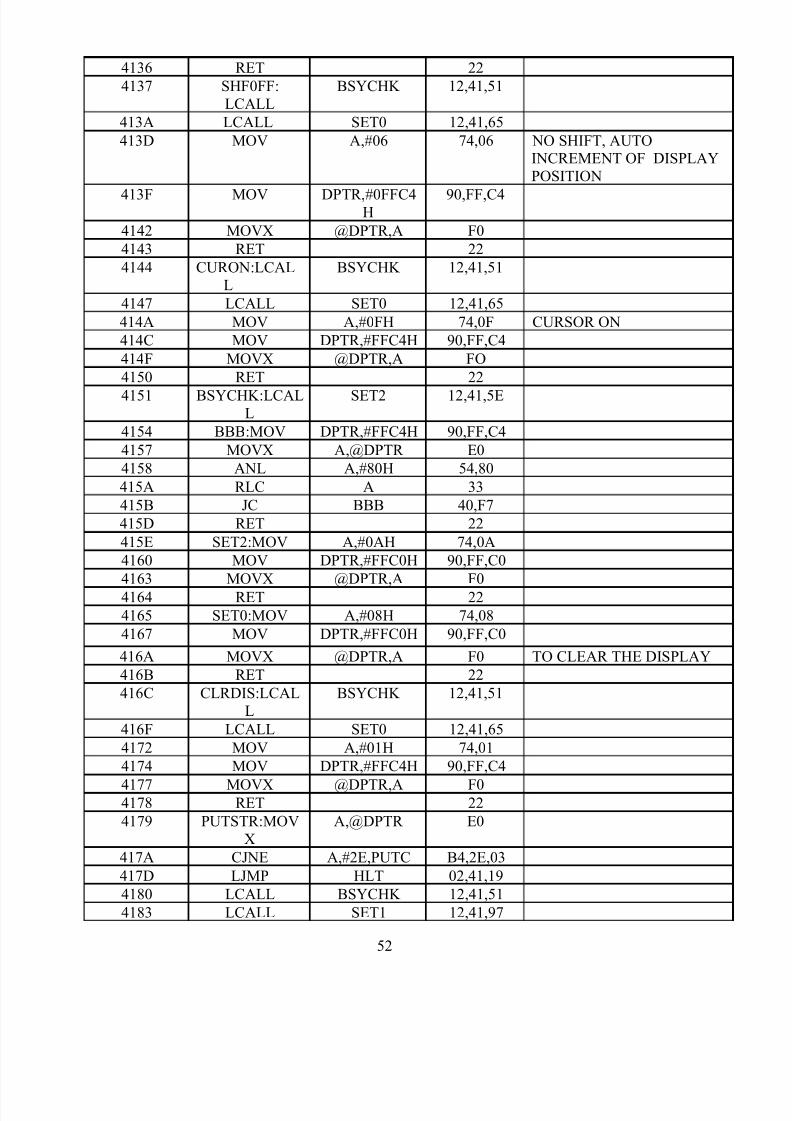
4136 RET 22
4137 SHF0FF:LCALL
BSYCHK 12,41,51
413A LCALL SET0 12,41,65
413D MOV A,#06 74,06 NO SHIFT, AUTOINCREMENT OF DISPLAYPOSITION
413F MOV DPTR,#0FFC4H
90,FF,C4
4142 MOVX @DPTR,A F0
4143 RET 22
4144 CURON:LCALL
BSYCHK 12,41,51
4147 LCALL SET0 12,41,65
414A MOV A,#0FH 74,0F CURSOR ON
414C MOV DPTR,#FFC4H 90,FF,C4
414F MOVX @DPTR,A FO
4150 RET 22
4151 BSYCHK:LCALL
SET2 12,41,5E
4154 BBB:MOV DPTR,#FFC4H 90,FF,C4
4157 MOVX A,@DPTR E0
4158 ANL A,#80H 54,80
415A RLC A 33
415B JC BBB 40,F7
415D RET 22
415E SET2:MOV A,#0AH 74,0A
4160 MOV DPTR,#FFC0H 90,FF,C0
4163 MOVX @DPTR,A F0
4164 RET 22
4165 SET0:MOV A,#08H 74,08
4167 MOV DPTR,#FFC0H 90,FF,C0
416A MOVX @DPTR,A F0 TO CLEAR THE DISPLAY
416B RET 22
416C CLRDIS:LCALL
BSYCHK 12,41,51
416F LCALL SET0 12,41,65
4172 MOV A,#01H 74,01
4174 MOV DPTR,#FFC4H 90,FF,C4
4177 MOVX @DPTR,A F04178 RET 22
4179 PUTSTR:MOVX
A,@DPTR E0
417A CJNE A,#2E,PUTC B4,2E,03
417D LJMP HLT 02,41,19
4180 LCALL BSYCHK 12,41,51
4183 LCALL SET1 12,41,97
52

8/3/2019 Micro Controller Programs
http://slidepdf.com/reader/full/micro-controller-programs 53/63
4186 MOV DPL,R1 89,82
4188 MOV DPH,R2 8A,83
418A MOVX A,@DPTR E0
418B MOV DPTR,#FFC4H 90,FF,C4
418E MOVX @DPTR,A F0
418F MOV DPL,R1 89,82
4191 MOV DPH,R2 8A,83 TO DISPLAY THE NEXT
LETTER 4193 INC R1 09
4194 LCALL PUSTR 12,41,79
4197 SET1:MOV A,#09H 74,09 WRITE DATA TO CG/DDRAM
4199 MOV DPTR,#FFC0H 90,FF,C0
419C MOVX @DPTR,A F0
419D RET 22
INPUT OUTPUT IN LCD DISPLAY
419E 43,4B,50,43 CKPC_ECE.
41A2 20,42,43,45
41A6 2E419E 43,4B,50,43 CKPC_EEE.
41A2 20,45,45,45
41A6 2E
PROGRAM FOR TRAFFIC LIGHT CONTROLORG 4100H
FF0F CONTRL EQU 0FF0FHFF0C PORTA EQU 0FF0CHFF0D PORTB EQU 0FF0DHFF0E PORTC EQU 0FF0EH
53

8/3/2019 Micro Controller Programs
http://slidepdf.com/reader/full/micro-controller-programs 54/63
ADDRESS MNEMONICS HEXCODE
OPCODE OPERAND
4100 MOV A,#80h 74 80
4102 MOV DPTR,#contrl 90 FF 0F
4105 MOVX @DPTR,A F0
4106 START:MOV R4,#04h 7C 04
4108 MOV DPTR,#LOOK1 90 41 9B
410B MOV R2,DPH AA 83410D MOV R3,DPL AB 82
410F MOV DPTR,#LOOK 90 41 8F
4112 MOV R0,DPH A8 83
4114 MOV R1,DPL A9 82
4116 GO:MOVX A,@DPTR E0
4117 MOV R0,DPH A8 83
4119 MOV R1,DPL A9 82
411B MOV DPTR,#porta 90 FF 0C
411E MOVX @DPTR,A F0
411F INC R1 09
4120 MOV DPH,R0 88 83
4122 MOV DPL,R1 89 82
4124 MOVX A,@DPTR E0
4125 MOV R0,DPH A8 83
4127 MOV R1,DPL A9 82
4129 MOV DPTR,#portb 90 FF 0D
412C MOVX @DPTR,a F0
412D INC R1 09
412E MOV DPH,R0 88 83
4130 MOV DPL,R1 89 82
4132 MOVX A,@DPTR E04133 MOV R0,DPH A8 83
4135 MOV R1,DPL A9 82
4137 MOV DPTR,#portc 90 FF 0E
413A MOVX @DPTR,A F0
413B INC R1 09
413C LCALL DELAY 12 41 75
413F MOV DPH,R2 8A 83
4141 MOV DPL,R3 8B 82
4143 MOVX A,@DPTR E0
4144 MOV R2,DPH AA 83
4146 MOV R3,DPL AB 82
Ex.No.4 TRAFFIC LIGHT CONTROL
AIM:
To write a program to interface TRAFFIC LIGH CONTROL with Micro controller.
APPARATUS REQUIRED:
54

8/3/2019 Micro Controller Programs
http://slidepdf.com/reader/full/micro-controller-programs 55/63
SI.no APPARATUS QUANTITY
1. Micro controller kit
1 No
2. Traffic light control board
1 No
PROCEDURE:
1. Connect the TLC interface card to micro controller kit.2. Enter the hex code in the R Memory starting from the location
4100.3. Execute the program.4. Observe the result in the Traffic Light Control board.
4148 MOV DPTR,#porta 90 FF 0C414B MOVX @DPTR,A F0
414C INC R3 0B
414D MOV DPH,R2 8A 83
414F MOV DPL,R3 8B 82
4151 MOVX A,@DPTR E0
4152 MOV R2,DPH AA 83
4154 MOV R3,DPL AB 82
55

8/3/2019 Micro Controller Programs
http://slidepdf.com/reader/full/micro-controller-programs 56/63
4156 MOV DPTR,portb 90 FF 0D
4159 MOVX @DPTR,A F0
415A INC R3 0B
415B MOV DPH,R2 8A 83
415D MOV DPL,R3 8B 82
415F MOVX A,@DPTR E0
4160 MOV R2,DPH AA 83
4162 MOV R3,DPL AB 824164 MOV DPTR,#portc 90 FF 0E
4167 MOVX @DPTR,A F0
4168 INC R3 0B
4169 LCALL DELAY1 12 41 82
416C MOV DPH,R0 88 83
416E MOV DPL,R1 89 82
4170 DJNZ R4,GO DC A4
4172 LCALL START 12 41 06
4175 DELAY:MOV R5,#12H 7D 12
4177 L3:MOV R6,#0FFH 7E FF
4179 L2:MOV R7,#0FFH 7F FF
417B L1:DJNZ R7,L1 DF FE
417D DJNZ R6,L2 DE FA
417F DJNZ R5,L3 DD F6
4181 RET 22
4182 DELAY1:MOV R5,#12H 7D 12
4184 L6:MOV R6,#0FFH 7E FF
4186 L5:MOV R7,#0FFH 7F FF
4188 L4:DJNZ R7,L4 DF FE
418A DJNZ R6,L5 DE FA
418C DJNZ R5,L6 DD F6418E RET 22
418F LOOK:DB 44H,27H,12H 44 27 12
4192 DB 92H,2BH,10H 92 2B 10
4195 DB 84H,9DH,10H 84 9D 10
4198 DB 84H,2EH,48H 84 2E 48
419B LOOK1:DB 48H,27H,12H 48 27 12
419E DB 92H,4BH,10H 92 4B 10
41A1 DB 84H,9DH,20H 84 9D 20
41A4 DB 04H,2EH,49H 04 2E 49
END
56

8/3/2019 Micro Controller Programs
http://slidepdf.com/reader/full/micro-controller-programs 57/63
RESULT:
Thus the program for interfacing of Traffic Light Control Board with microcontroller is executed and output is observed in Traffic Light Control Board.
STEPPER MOTOR PROGRAM
MEMORYADDRESS
MNEMONICS HEXCODE
Opcode Operand
4100 ORG 4100H
4100 START:MOV DPTR,#4500H 90,45,00
57

8/3/2019 Micro Controller Programs
http://slidepdf.com/reader/full/micro-controller-programs 58/63
4103 MOV R0,#04H 78,04
4105 JO:MOVX A,@DPTR E0
4106 PUSH DPH C0,83
4108 PUSH DPL C0,82
410A MOV DPTR,#FFC0H 90,FF,C0
410D MOV R2,#04H 7A,04
410F MOV R1,#0FH 79,0F
4111 DLY1:MOV R3,#0FH 7B,0F
4113 DLY:DJNZ R3,DLY DB,FE
4115 DJNZ R1,DLY1 D9,FA
4117 DJNZ R2,DLY1 DA,F8
4119 MOVX @DPTR,A F0
411A POP DPL D0,82
411C POP DPH D0,83
411E INC DPTR A3
411F DJNZ R0,JO D8,E4
4121 SJMP START 80,DD
4123 END 80,DD
INPUT STEPPER MOTOR ROTATION
4500 09,05,06,0A FORWARD DIRECTION
4500 0A,06,05,09 REVERSE DIRECTION
Ex.No:5
INTERFACING OF STEPPERMOTOR
AIM:
To write a program to interface stepper motor with micro controller.
APPARATUS REQUIRED:
58

8/3/2019 Micro Controller Programs
http://slidepdf.com/reader/full/micro-controller-programs 59/63
SI.no APPARATUS QUANTITY
1. Micro controller kit
1 No
2. Stepper motor 1 No
3. Interface card 1 No
PROCEDURE:
1. Connect the Stepper motor interface card to micro controller kit.2. Enter the hex code in the RAM Memory starting from the location3. 4100.Execute the program.4. observe the result in rotation of stepper motor.
RESULT:
Thus the program for stepper motor interface with microcontroller kit is executedand output is observed in rotation of stepper motor.
PROGRAM FOR LIFT CONTROL
0001 T0_m1 EQU 01H0030 COUNT EQU 30H0031 COUNT1 EQU 31HFFC0 LIFT1 EQU 0FFC0HFFC4 LIFT2 EQU 0FFC4HFFC8 STAT_IN EQU 0FFC8H
59

8/3/2019 Micro Controller Programs
http://slidepdf.com/reader/full/micro-controller-programs 60/63
FFCC STAT_0U EQU 0FFCCHORG 4100
ADDRESS MNEMONICS HEXCODE COMMENT
OPCODE OPERAND
4100 START:MOV A,#03H 74,03
4102 MOV DPTR,#STAT_
OU
90,FF,CC DEFAULT OPEN
DOORS OF LIFT1 & 24105 MOVX @DPTR,A F0
4106 CALL DELAY 12,41,41
4109 MOV A,#02H 74,02 CLOSE DOOR OFLIFT1
410B MOVX @DPTR,A F0
410C MOV A,#80H 74,80
410E MOV DPTR,#LIFT1 90,FF,C0 INDICATES LIFT 1IN GROUND FLOOR
4111 MOVX @DPTR,A F0
4112 MOV A,#01H 74,01
4114 MOV DPTR,#LIFT2 90,FF,C4 INDICATES LIFT 2IN 7TH FLOOR
4117 MOVX @DPTR,A F0
4118 CALL DELAY 12,41,41
411B MOV DPTR,#LIFT1 90,FF,C0
411E MOV A,#40H 74,40
4120 MOVX @DPTR,A F0
4121 CALL DELAY 12,41,41
4124 MOV A,#20H 74,20
4126 MOVX @DPTR,A F0
4127 CALL DELAY 12,41,41
412A MOV A,#10H 74,10
412C MOVX @DPTR,A F0
412D CALL DELAY 12,41,41
4130 MOV A,#08H 74,08
4132 MOVX @DPTR,A F0
4133 MOV A,#0BH 74,0B BEEP FOR DOOR OPEN
4135 MOV DPTR,#STAT_ OU
90,FF,CC
Ex.No.6 LIFT CONTROL
AIM:
To write a program to interface LIFT CONTROL with Micro controller.
APPARATUS REQUIRED:
60

8/3/2019 Micro Controller Programs
http://slidepdf.com/reader/full/micro-controller-programs 61/63
SI.no APPARATUS QUANTITY
1. Micro controller kit
1 No
2. Lift control interface 1 No
PROCEDURE:
1. Connect the lift control interface card to micro controller kit.2. Enter the hex code in the R Memory starting from the location
4100.3. Execute the program.4. Observe the result in the lift Control board.
4138 MOVX @DPTR,A F04139 CALL DELAY 12,41,41
413C MOV A,#03H 74,03 OPEN DOORS
413E MOVX @DPTR,A F0
413F HERE:SJMP HER 80,FE
4141 DELAY:MOV COUNT1,#10 75,31,0A FOR 1 SECONDDELAY
4144 DL2:MOV COUNT,#100 75,30,64
61

8/3/2019 Micro Controller Programs
http://slidepdf.com/reader/full/micro-controller-programs 62/63
4147 D2:CALL DELAY 1 MS 12,41,51
414A DJNZ COUNT,D2 D5,30,FA
414D DJNZ COUNT1,DL2 D5,31,F4
4150 RET 22
4151 DELAY1 ms: MOV
DL0,#17H 75,8A,17 THE LOW BYTE OFTIMER 0(TL0=17H)
4154 MOV DH0,#FCH 75,8C,FC THE HIGH BYTE OF
TIMER 0(TH0=FCH)4157 CALL T0 DELAY 12,41,5B ACTIVATE THE
TIMER 0 AND WAITUPTO TIMER OVERFLOW
OCCURS
415A RET 22
415B T0 DELAY:MOV
A,TMOD E5,89
415D ANL A,#F0H 54,F0
415F ORL A,#T0_M1 44,01
4161 MOV TMOD,A F5,89 2 TIMER 0,MODE 14163 SETB TR0 D2,8C 1 START TIMER 0
4165 JNB TFO,$ 30,8D,FD 0FFFF-(16 BIT TIMER VALUE)+1;
MONITOR TIMER FLAG 0
4168 CLR TR0 C2,8C 1 STOP THE TIMER 0
416A CLR TF0 C2,8D 1 CLEAR TIMER FLAG 0
416C RET 22 1 RETURN FROMSUBROUTINE
END
62
8/3/2019 Micro Controller Programs
http://slidepdf.com/reader/full/micro-controller-programs 63/63
RESULT:
Thus the program for interfacing of Lift Control Board with micro controller isexecuted and output is observed in Lift Control Board.