
Micro Controller File
50
Experiment No. - 4(a) Batch: EC-A2 Date: Aim: a) Write a a ssembly lan guage p rogra m to exch ange th e conten t of FFh a nd FF0h. Software tool used: Keil µvision v 4.02 Logical description: Here, FFh and FF0h are memory address of external ROM. For accessing the external ROM instruction MOVX A,@DPTR is used. First load the address FF0h in dptr and by using above equation load the data of FF0h in accumulator then store it temporarily in another register. Now as above process data stored in FFh can be loaded in accumulator. To send this data to FF0h Dptr sets to FF0h agai n and by instruction MOV @DPTR,A the data can be stored back to the external memory address FF0h. For FFh, load the temporarily register data in accumulator and by using above instru ction the data can be stored back to FFh. This way we can exchang e the data of FFH and FF0h. Here MOVX instruction works only with accumulator, so it is necessary to load content in accumulator which u want to copy in external memory. Process 1: Process 2: Process 3: Memory address FF0 h Memory address FF h Accumulator Re ister B
-
Upload
ankur-patel -
Category
Documents
-
view
234 -
download
0
Transcript of Micro Controller File
8/3/2019 Micro Controller File
http://slidepdf.com/reader/full/micro-controller-file 1/50
Experiment No. - 4(a)
Batch: EC-A2 Date:
Aim: a) Write a assembly language program to exchange the content of FFh and
FF0h.
Software tool used: Keil µvision v 4.02
Logical description:
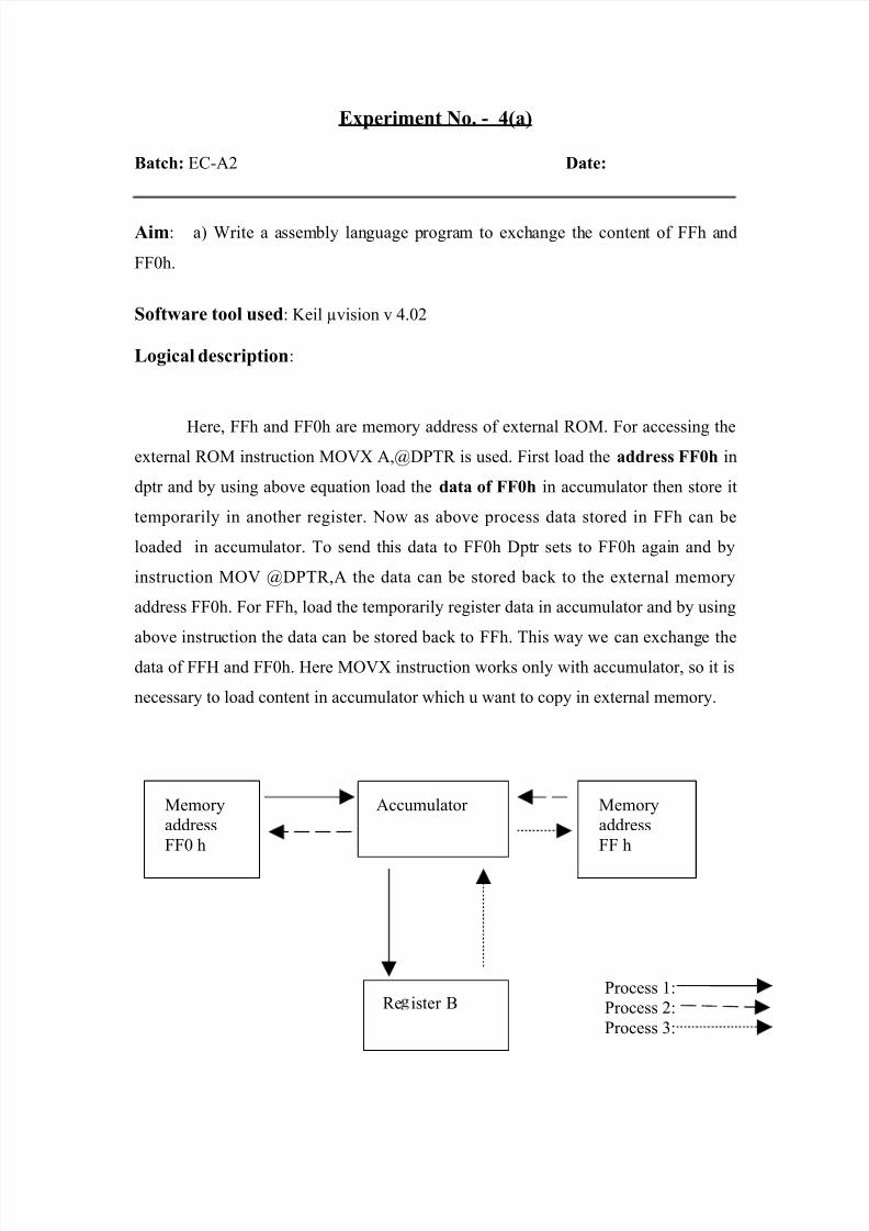
Here, FFh and FF0h are memory address of external ROM. For accessing theexternal ROM instruction MOVX A,@DPTR is used. First load the address FF0h in
dptr and by using above equation load the data of FF0h in accumulator then store it
temporarily in another register. Now as above process data stored in FFh can be
loaded in accumulator. To send this data to FF0h Dptr sets to FF0h again and by
instruction MOV @DPTR,A the data can be stored back to the external memory
address FF0h. For FFh, load the temporarily register data in accumulator and by using
above instruction the data can be stored back to FFh. This way we can exchange the
data of FFH and FF0h. Here MOVX instruction works only with accumulator, so it is
necessary to load content in accumulator which u want to copy in external memory.
Process 1:
Process 2:
Process 3:
Memory
address
FF0 h
Memory
address
FF h
Accumulator
Re ister B
8/3/2019 Micro Controller File
http://slidepdf.com/reader/full/micro-controller-file 2/50
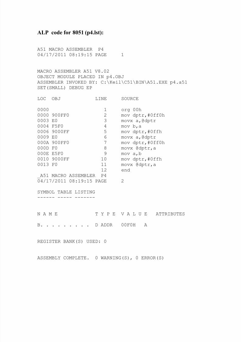
ALP code for 8051 (p4.lst):
A51 MACRO ASSEMBLER P404/17/2011 08:19:15 PAGE 1
MACRO ASSEMBLER A51 V8.02OBJECT MODULE PLACED IN p4.OBJASSEMBLER INVOKED BY: C:\Keil\C51\BIN\A51.EXE p4.a51SET(SMALL) DEBUG EP
LOC OBJ LINE SOURCE
0000 1 org 00h0000 900FF0 2 mov dptr,#0ff0h
0003 E0 3 movx a,@dptr0004 F5F0 4 mov b,a0006 9000FF 5 mov dptr,#0ffh0009 E0 6 movx a,@dptr000A 900FF0 7 mov dptr,#0ff0h000D F0 8 movx @dptr,a000E E5F0 9 mov a,b0010 9000FF 10 mov dptr,#0ffh0013 F0 11 movx @dptr,a
12 end_A51 MACRO ASSEMBLER P4
04/17/2011 08:19:15 PAGE 2
SYMBOL TABLE LISTING------ ----- -------
N A M E T Y P E V A L U E ATTRIBUTES
B. . . . . . . . . D ADDR 00F0H A
REGISTER BANK(S) USED: 0
ASSEMBLY COMPLETE. 0 WARNING(S), 0 ERROR(S)
8/3/2019 Micro Controller File
http://slidepdf.com/reader/full/micro-controller-file 3/50
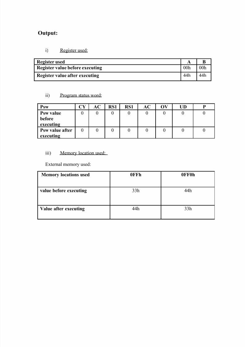
Output:
i) Register used:
Register used A BRegister value before executing 00h 00h
Register value after executing 44h 44h
ii) Program status word:
Psw CY AC RS1 RS1 AC OV UD P
Psw value
before
executing
0 0 0 0 0 0 0 0
Psw value after
executing
0 0 0 0 0 0 0 0
iii) Memory location used:
External memory used:
Memory locations used 0FFh 0FF0h
value before executing 33h 44h
Value after executing 44h 33h
8/3/2019 Micro Controller File
http://slidepdf.com/reader/full/micro-controller-file 4/50
Experiment No. - 4(b)
Batch: EC-A2 Date:
Aim: b) Write a assembly language program to store the higher nibble of R7 into
both nibbles of R6.
Software tool used: Keil µvision v 4.02
Logical description:
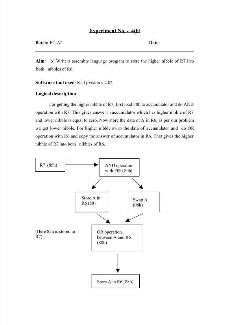
For getting the higher nibble of R7, first load F0h to accumulator and do AND
operation with R7. This gives answer in accumulator which has higher nibble of R7and lower nibble is equal to zero. Now store the data of A in R6, as per our problem
we get lower nibble. For higher nibble swap the data of accumulator and do OR
operation with R6 and copy the answer of accumulator in R6. That gives the higher
nibble of R7 into both nibbles of R6.
(Here 85h is stored in
R7)OR operation
between A and R6
(88h)
R7 (85h) AND operation
with F0h 80h
Swap A
(08h)
Store A in
R6 (80)
Store A in R6 (88h)
8/3/2019 Micro Controller File
http://slidepdf.com/reader/full/micro-controller-file 5/50
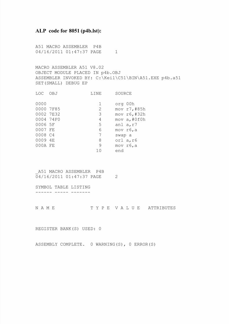
ALP code for 8051 (p4b.lst):
A51 MACRO ASSEMBLER P4B04/16/2011 01:47:37 PAGE 1
MACRO ASSEMBLER A51 V8.02OBJECT MODULE PLACED IN p4b.OBJASSEMBLER INVOKED BY: C:\Keil\C51\BIN\A51.EXE p4b.a51SET(SMALL) DEBUG EP
LOC OBJ LINE SOURCE
0000 1 org 00h0000 7F85 2 mov r7,#85h
0002 7E32 3 mov r6,#32h0004 74F0 4 mov a,#0f0h0006 5F 5 anl a,r70007 FE 6 mov r6,a0008 C4 7 swap a0009 4E 8 orl a,r6000A FE 9 mov r6,a
10 end
_A51 MACRO ASSEMBLER P4B04/16/2011 01:47:37 PAGE 2
SYMBOL TABLE LISTING------ ----- -------
N A M E T Y P E V A L U E ATTRIBUTES
REGISTER BANK(S) USED: 0
ASSEMBLY COMPLETE. 0 WARNING(S), 0 ERROR(S)
8/3/2019 Micro Controller File
http://slidepdf.com/reader/full/micro-controller-file 6/50
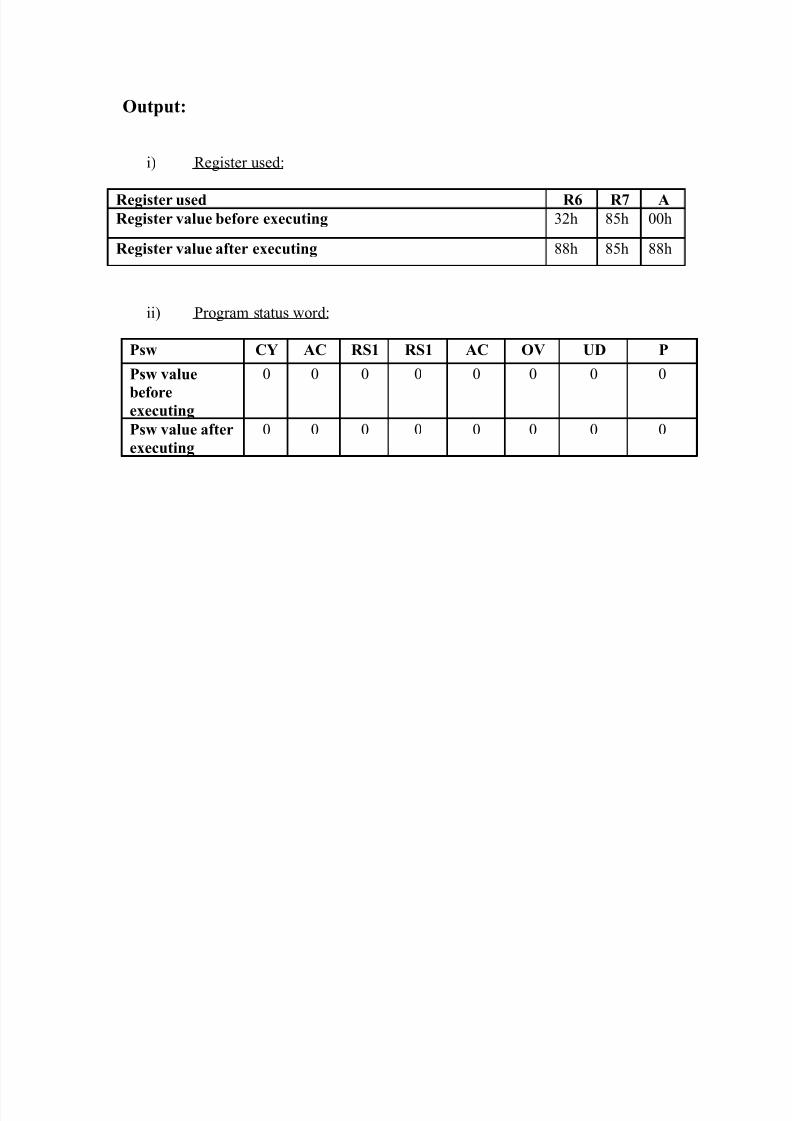
Output:
i) Register used:
Register used R6 R7 ARegister value before executing 32h 85h 00h
Register value after executing 88h 85h 88h
ii) Program status word:
Psw CY AC RS1 RS1 AC OV UD P
Psw value
beforeexecuting
0 0 0 0 0 0 0 0
Psw value after
executing
0 0 0 0 0 0 0 0

8/3/2019 Micro Controller File
http://slidepdf.com/reader/full/micro-controller-file 7/50
Practical No: 05(A)
Batch: EC-A2 Date:
Aim: Develop assembly language code: Read R6, R7 & R4, R5 as two 16-bit
registers perform subtraction between them store the result in 20th lower byte & 21st
higher byte.
Tools used: keil µvision 4.02
Logical description:
For this instruction SUBB is used which subtract to content
considering the carry flag. For 16 bit register first subtract the data of R7 and R5. The
accumulator having the answer, store it to 20h address of internal RAM. Now subtract
the data of R6 and R4. If the carry flag is set then instruction consider carry and do
subtraction with using that carry. Store that answer in 21h. At the end we get full
answer stored in 20h to 21h.
Process 1:
send
Process 2:
send
R6
R4
R7
R5
Memory
address21h
SUBB
A,R4
SUBB
A,R5
Memory
address
20h
A
A
8/3/2019 Micro Controller File
http://slidepdf.com/reader/full/micro-controller-file 8/50
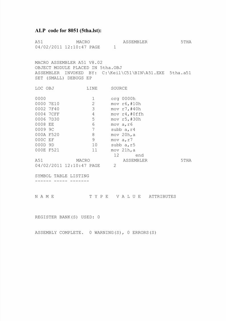
ALP code for 8051 (5tha.lst):
A51 MACRO ASSEMBLER 5THA04/02/2011 12:10:47 PAGE 1
MACRO ASSEMBLER A51 V8.02OBJECT MODULE PLACED IN 5tha.OBJASSEMBLER INVOKED BY: C:\Keil\C51\BIN\A51.EXE 5tha.a51SET (SMALL) DEBUGS EP
LOC OBJ LINE SOURCE
0000 1 org 0000h0000 7E10 2 mov r6,#10h0002 7F40 3 mov r7,#40h0004 7CFF 4 mov r4,#0ffh0006 7D30 5 mov r5,#30h0008 EE 6 mov a,r60009 9C 7 subb a,r4000A F520 8 mov 20h,a000C EF 9 mov a,r7000D 9D 10 subb a,r5000E F521 11 mov 21h,a
12 endA51 MACRO ASSEMBLER 5THA04/02/2011 12:10:47 PAGE 2
SYMBOL TABLE LISTING------ ----- -------
N A M E T Y P E V A L U E ATTRIBUTES
REGISTER BANK(S) USED: 0
ASSEMBLY COMPLETE. 0 WARNING(S), 0 ERRORS(S)
8/3/2019 Micro Controller File
http://slidepdf.com/reader/full/micro-controller-file 9/50
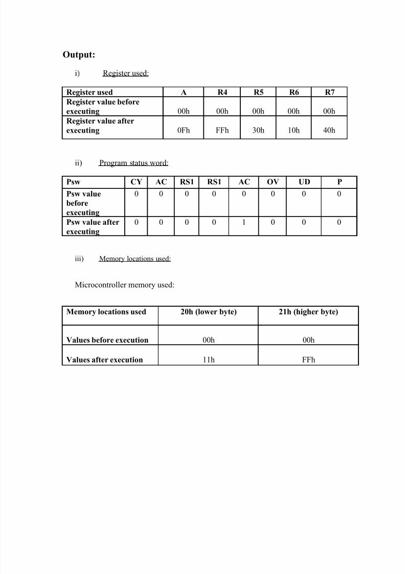
Output:
i) Register used:
Register used A R4 R5 R6 R7
Register value beforeexecuting 00h 00h 00h 00h 00h
Register value after
executing 0Fh FFh 30h 10h 40h
ii) Program status word:
Psw CY AC RS1 RS1 AC OV UD P
Psw value
beforeexecuting
0 0 0 0 0 0 0 0
Psw value after
executing
0 0 0 0 1 0 0 0
iii) Memory locations used:
Microcontroller memory used:
Memory locations used 20h (lower byte) 21h (higher byte)
Values before execution 00h 00h
Values after execution 11h FFh
8/3/2019 Micro Controller File
http://slidepdf.com/reader/full/micro-controller-file 10/50
Experiment No. - 5(b)
Batch: EC-A2 Date:
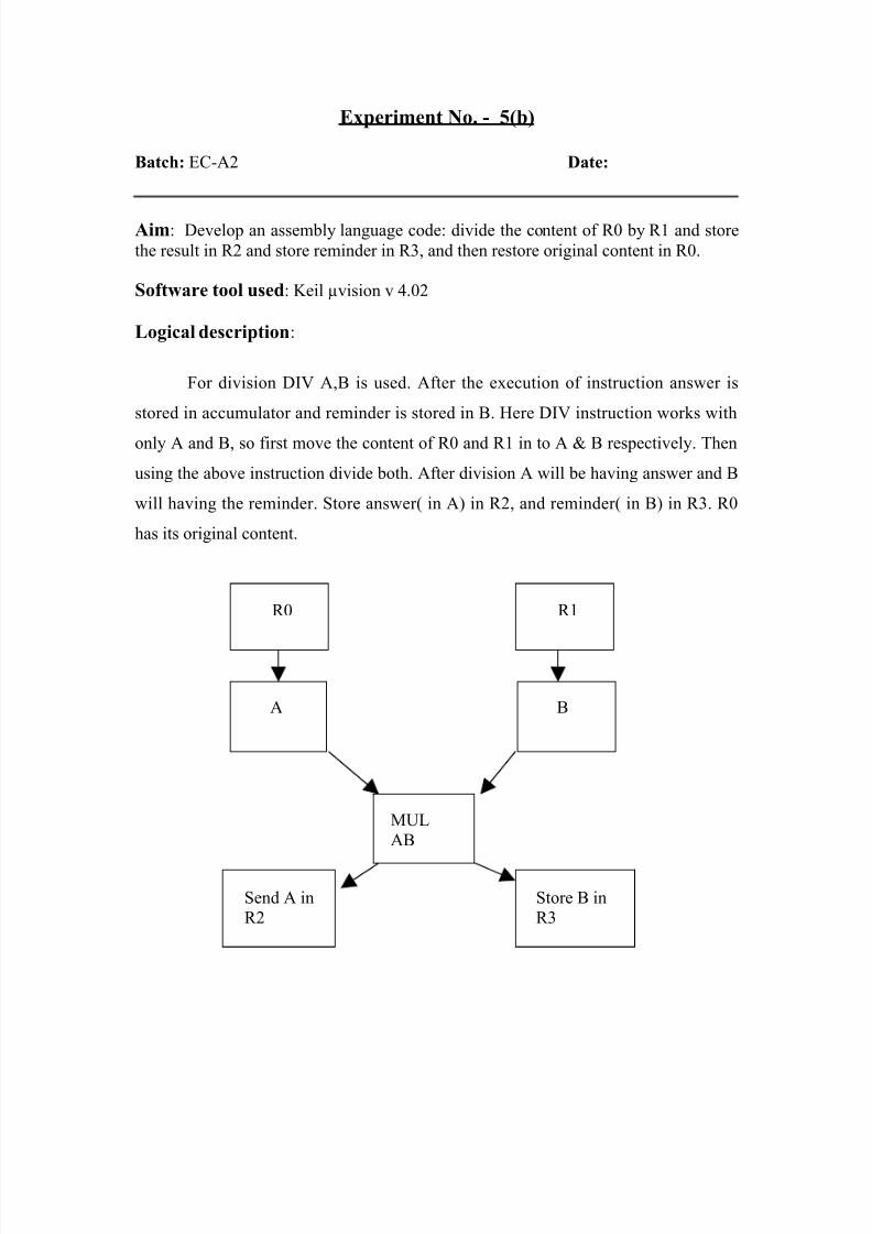
Aim: Develop an assembly language code: divide the content of R0 by R1 and store
the result in R2 and store reminder in R3, and then restore original content in R0.
Software tool used: Keil µvision v 4.02
Logical description:
For division DIV A,B is used. After the execution of instruction answer is
stored in accumulator and reminder is stored in B. Here DIV instruction works with
only A and B, so first move the content of R0 and R1 in to A & B respectively. Then
using the above instruction divide both. After division A will be having answer and B
will having the reminder. Store answer( in A) in R2, and reminder( in B) in R3. R0
has its original content.
A
R1R0
B
MUL
AB
Send A in
R2
Store B in
R3
8/3/2019 Micro Controller File
http://slidepdf.com/reader/full/micro-controller-file 11/50
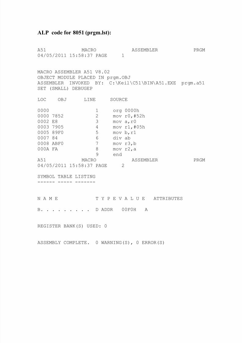
ALP code for 8051 (prgm.lst):
A51 MACRO ASSEMBLER PRGM04/05/2011 15:58:37 PAGE 1
MACRO ASSEMBLER A51 V8.02OBJECT MODULE PLACED IN prgm.OBJASSEMBLER INVOKED BY: C:\Keil\C51\BIN\A51.EXE prgm.a51SET (SMALL) DEBUGEP
LOC OBJ LINE SOURCE
0000 1 org 0000h0000 7852 2 mov r0,#52h
0002 E8 3 mov a,r00003 7905 4 mov r1,#05h0005 89F0 5 mov b,r10007 84 6 div ab0008 ABF0 7 mov r3,b000A FA 8 mov r2,a
9 endA51 MACRO ASSEMBLER PRGM04/05/2011 15:58:37 PAGE 2
SYMBOL TABLE LISTING------ ----- -------
N A M E T Y P E V A L U E ATTRIBUTES
B. . . . . . . . . D ADDR 00F0H A
REGISTER BANK(S) USED: 0
ASSEMBLY COMPLETE. 0 WARNING(S), 0 ERROR(S)
8/3/2019 Micro Controller File
http://slidepdf.com/reader/full/micro-controller-file 12/50
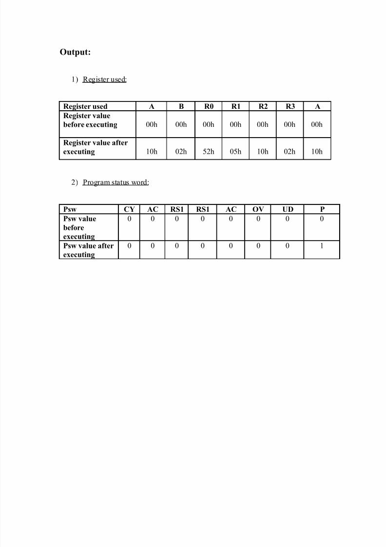
Output:
1) Register used:
Register used A B R0 R1 R2 R3 A
Register value
before executing 00h 00h 00h 00h 00h 00h 00h
Register value after
executing 10h 02h 52h 05h 10h 02h 10h
2) Program status word:
Psw CY AC RS1 RS1 AC OV UD P
Psw value
before
executing
0 0 0 0 0 0 0 0
Psw value after
executing
0 0 0 0 0 0 0 1
8/3/2019 Micro Controller File
http://slidepdf.com/reader/full/micro-controller-file 13/50
Experiment No. - 6
Batch: EC-A2 Date:
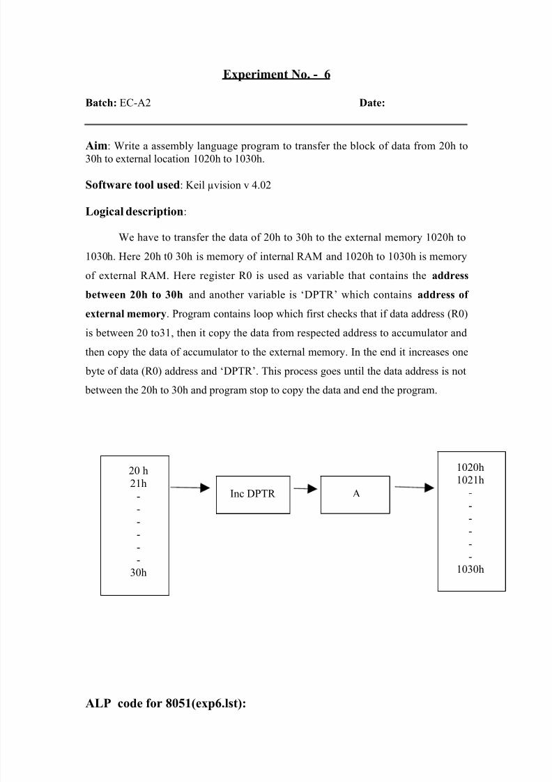
Aim: Write a assembly language program to transfer the block of data from 20h to
30h to external location 1020h to 1030h.
Software tool used: Keil µvision v 4.02
Logical description:
We have to transfer the data of 20h to 30h to the external memory 1020h to
1030h. Here 20h t0 30h is memory of internal RAM and 1020h to 1030h is memory
of external RAM. Here register R0 is used as variable that contains the address
between 20h to 30h and another variable is ‘DPTR’ which contains address of
external memory. Program contains loop which first checks that if data address (R0)
is between 20 to31, then it copy the data from respected address to accumulator and
then copy the data of accumulator to the external memory. In the end it increases one
byte of data (R0) address and ‘DPTR’. This process goes until the data address is not
between the 20h to 30h and program stop to copy the data and end the program.
ALP code for 8051(exp6.lst):
20 h
21h
-
-
-
-
--
30h
1020h
1021h
-
-
-
-
--
1030h
AInc DPTR
8/3/2019 Micro Controller File
http://slidepdf.com/reader/full/micro-controller-file 14/50
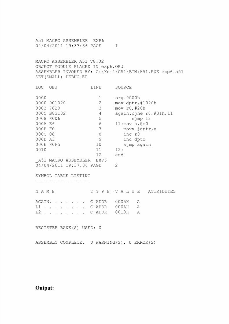
A51 MACRO ASSEMBLER EXP604/04/2011 19:37:36 PAGE 1
MACRO ASSEMBLER A51 V8.02OBJECT MODULE PLACED IN exp6.OBJASSEMBLER INVOKED BY: C:\Keil\C51\BIN\A51.EXE exp6.a51SET(SMALL) DEBUG EP
LOC OBJ LINE SOURCE
0000 1 org 0000h0000 901020 2 mov dptr,#1020h0003 7820 3 mov r0,#20h
0005 B83102 4 again:cjne r0,#31h,l10008 8006 5 sjmp l2000A E6 6 l1:mov a,@r0000B F0 7 movx @dptr,a000C 08 8 inc r0000D A3 9 inc dptr000E 80F5 10 sjmp again0010 11 l2:
12 end_A51 MACRO ASSEMBLER EXP604/04/2011 19:37:36 PAGE 2
SYMBOL TABLE LISTING------ ----- -------
N A M E T Y P E V A L U E ATTRIBUTES
AGAIN. . . . . . . C ADDR 0005H AL1 . . . . . . . . C ADDR 000AH AL2 . . . . . . . . C ADDR 0010H A
REGISTER BANK(S) USED: 0
ASSEMBLY COMPLETE. 0 WARNING(S), 0 ERROR(S)
Output:
8/3/2019 Micro Controller File
http://slidepdf.com/reader/full/micro-controller-file 15/50
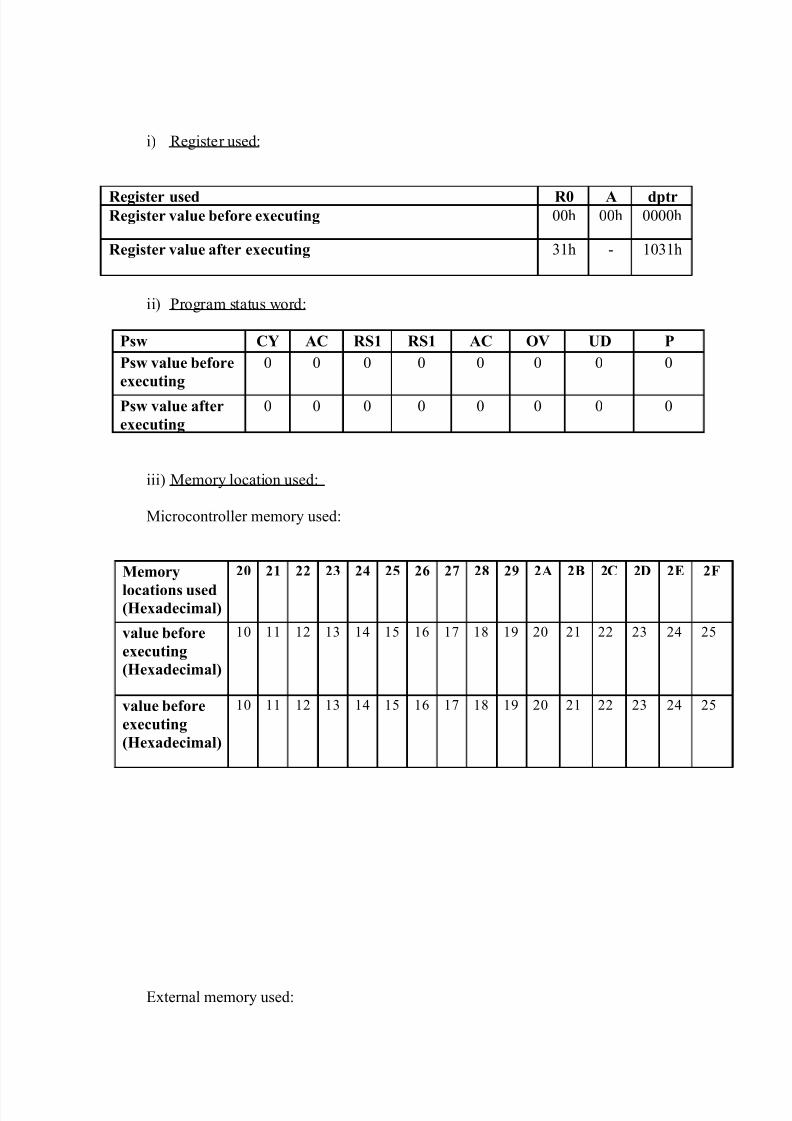
i) Register used:
Register used R0 A dptrRegister value before executing 00h 00h 0000h
Register value after executing 31h - 1031h
ii) Program status word:
Psw CY AC RS1 RS1 AC OV UD P
Psw value before
executing
0 0 0 0 0 0 0 0
Psw value after
executing
0 0 0 0 0 0 0 0
iii) Memory location used:
Microcontroller memory used:
Memory
locations used(Hexadecimal)
20 21 22 23 24 25 26 27 28 29 2A 2B 2C 2D 2E 2F
value before
executing
(Hexadecimal)
10 11 12 13 14 15 16 17 18 19 20 21 22 23 24 25
value before
executing
(Hexadecimal)
10 11 12 13 14 15 16 17 18 19 20 21 22 23 24 25
External memory used:
8/3/2019 Micro Controller File
http://slidepdf.com/reader/full/micro-controller-file 16/50
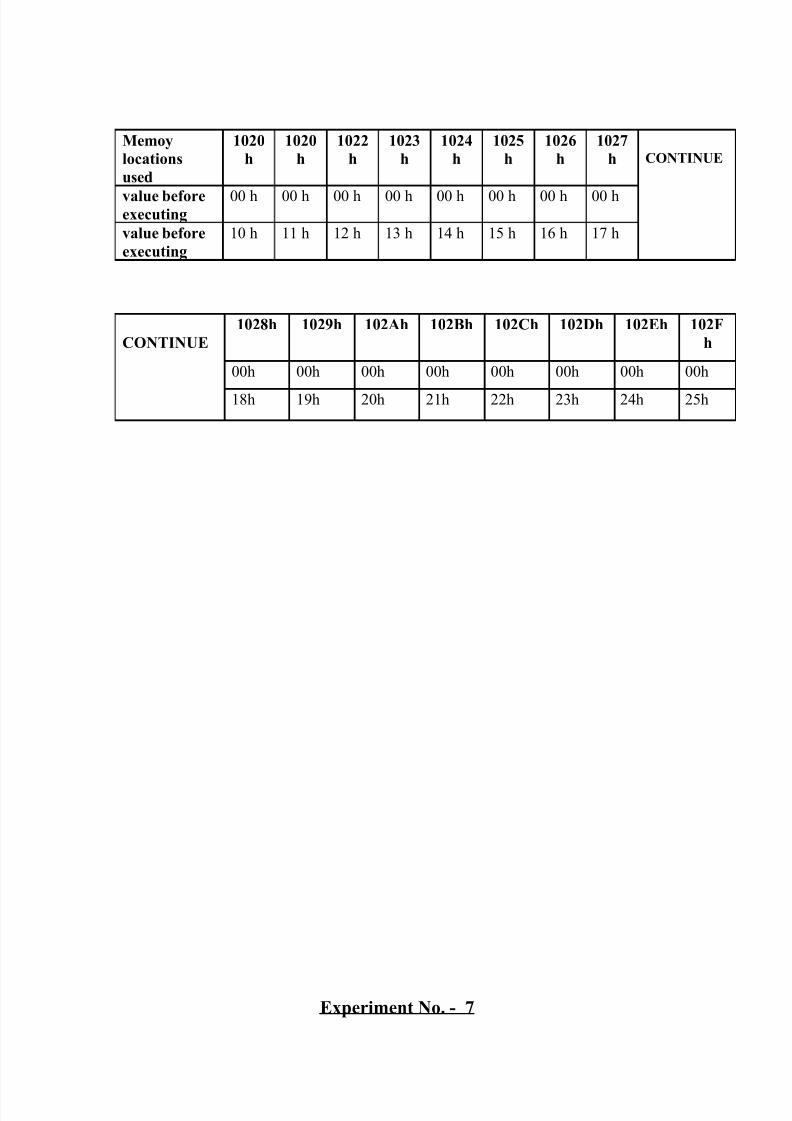
Experiment No. - 7
Memoy
locations
used
1020
h
1020
h
1022
h
1023
h
1024
h
1025
h
1026
h
1027
h CONTINUE
value beforeexecuting
00 h 00 h 00 h 00 h 00 h 00 h 00 h 00 h
value before
executing
10 h 11 h 12 h 13 h 14 h 15 h 16 h 17 h
CONTINUE
1028h 1029h 102Ah 102Bh 102Ch 102Dh 102Eh 102F
h
00h 00h 00h 00h 00h 00h 00h 00h
18h 19h 20h 21h 22h 23h 24h 25h

8/3/2019 Micro Controller File
http://slidepdf.com/reader/full/micro-controller-file 17/50
Batch: EC-A2 Date:
Aim: Write a assembly language program to find out how many equals bytes between
two memory box 10h to 20h and 20h to 30h.
Software tool used: Keil µvision v 4.02
Logical description:
The logic of program is very simple depend upon the nested loop. There are
two blocks first is 10h to 20h and second is 20h to 30h. In program data of one
register of first block (10h to 20h) is compared with data of all registers of second
block (20h to 30h).after this second register (12h) is compared with data of all
registers. If the bytes are same than counter will increment. This process will continue
until all data are compared with each other.
Most important thing for program is clear the carry flag when conditions of
address is check than if address is small than carry flag will be set and that affect the
instruction SUBB gives wrong answer, so it is necessary to clear carry after every
comparison and subtraction.
ALP code for 8051(p7.lst):
8/3/2019 Micro Controller File
http://slidepdf.com/reader/full/micro-controller-file 18/50
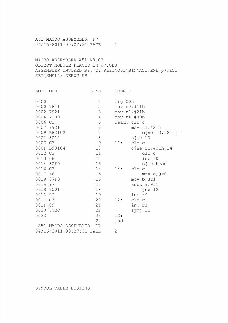
A51 MACRO ASSEMBLER P704/16/2011 00:27:31 PAGE 1
MACRO ASSEMBLER A51 V8.02OBJECT MODULE PLACED IN p7.OBJASSEMBLER INVOKED BY: C:\Keil\C51\BIN\A51.EXE p7.a51SET(SMALL) DEBUG EP
LOC OBJ LINE SOURCE
0000 1 org 00h0000 7811 2 mov r0,#11h
0002 7921 3 mov r1,#21h0004 7C00 4 mov r4,#00h0006 C3 5 head: clr c0007 7921 6 mov r1,#21h0009 B82102 7 cjne r0,#21h,l1000C 8014 8 sjmp l3000E C3 9 l1: clr c000F B93104 10 cjne r1,#31h,l40012 C3 11 clr c0013 08 12 inc r00014 80F0 13 sjmp head
0016 C3 14 l4: clr c0017 E6 15 mov a,@r00018 87F0 16 mov b,@r1001A 97 17 subb a,@r1001B 7001 18 jnz l2001D 0C 19 inc r4001E C3 20 l2: clr c001F 09 21 inc r10020 80EC 22 sjmp l10022 23 l3:
24 end
_A51 MACRO ASSEMBLER P704/16/2011 00:27:31 PAGE 2
SYMBOL TABLE LISTING
8/3/2019 Micro Controller File
http://slidepdf.com/reader/full/micro-controller-file 19/50
------ ----- -------
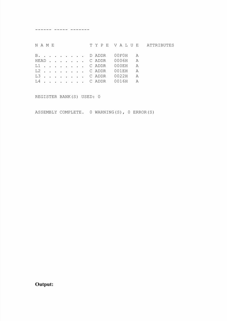
N A M E T Y P E V A L U E ATTRIBUTES
B. . . . . . . . . D ADDR 00F0H AHEAD . . . . . . . C ADDR 0006H AL1 . . . . . . . . C ADDR 000EH AL2 . . . . . . . . C ADDR 001EH AL3 . . . . . . . . C ADDR 0022H AL4 . . . . . . . . C ADDR 0016H A
REGISTER BANK(S) USED: 0
ASSEMBLY COMPLETE. 0 WARNING(S), 0 ERROR(S)
Output:
8/3/2019 Micro Controller File
http://slidepdf.com/reader/full/micro-controller-file 20/50
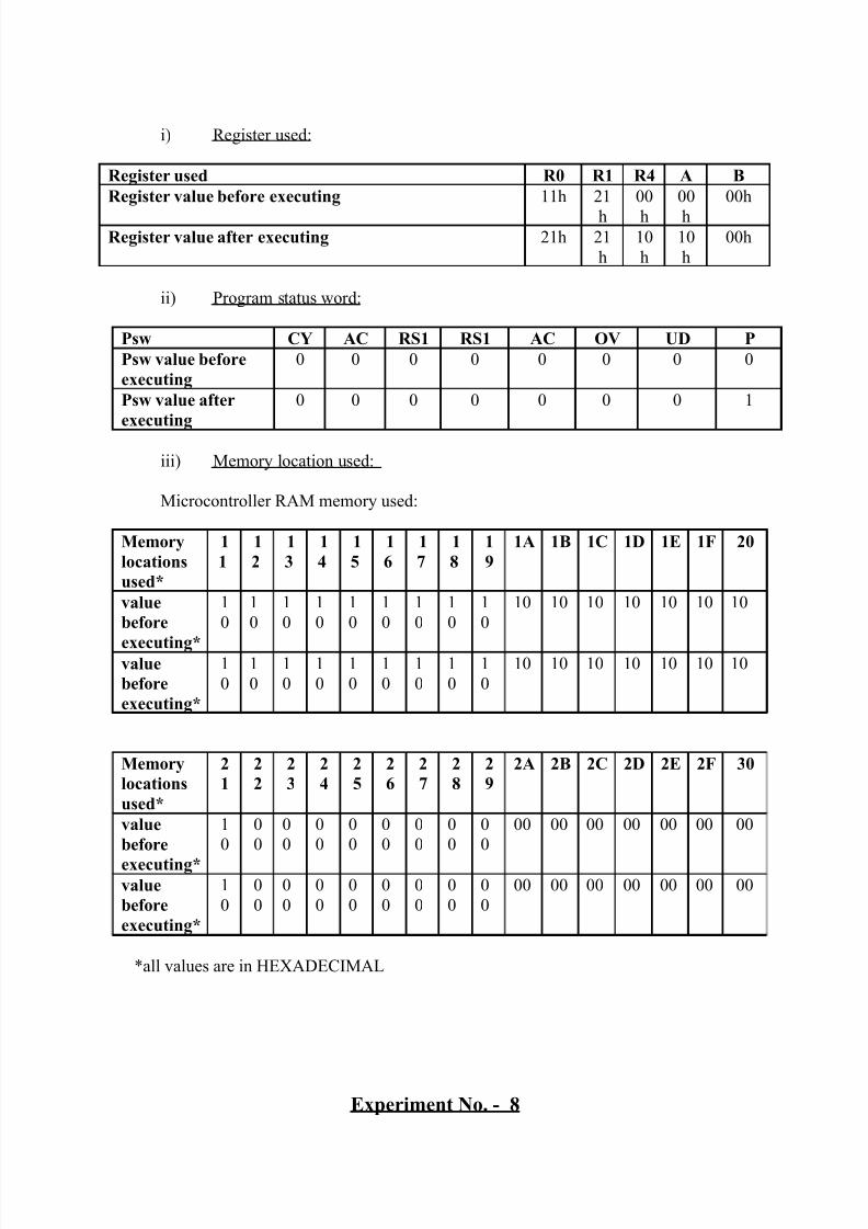
i) Register used:
Register used R0 R1 R4 A B
Register value before executing 11h 21
h
00
h
00
h
00h
Register value after executing 21h 21
h
10
h
10
h
00h
ii) Program status word:
Psw CY AC RS1 RS1 AC OV UD P
Psw value before
executing
0 0 0 0 0 0 0 0
Psw value after
executing
0 0 0 0 0 0 0 1
iii) Memory location used:
Microcontroller RAM memory used:
Memory
locations
used*
1
1
1
2
1
3
1
4
1
5
1
6
1
7
1
8
1
9
1A 1B 1C 1D 1E 1F 20
value
before
executing*
1
0
1
0
1
0
1
0
1
0
1
0
1
0
1
0
1
0
10 10 10 10 10 10 10
value
before
executing*
1
0
1
0
1
0
1
0
1
0
1
0
1
0
1
0
1
0
10 10 10 10 10 10 10
*all values are in HEXADECIMAL
Experiment No. - 8
Memory
locations
used*
2
1
2
2
2
3
2
4
2
5
2
6
2
7
2
8
2
9
2A 2B 2C 2D 2E 2F 30
value
before
executing*
1
0
0
0
0
0
0
0
0
0
0
0
0
0
0
0
0
0
00 00 00 00 00 00 00
value
before
executing*
1
0
0
0
0
0
0
0
0
0
0
0
0
0
0
0
0
0
00 00 00 00 00 00 00
8/3/2019 Micro Controller File
http://slidepdf.com/reader/full/micro-controller-file 21/50
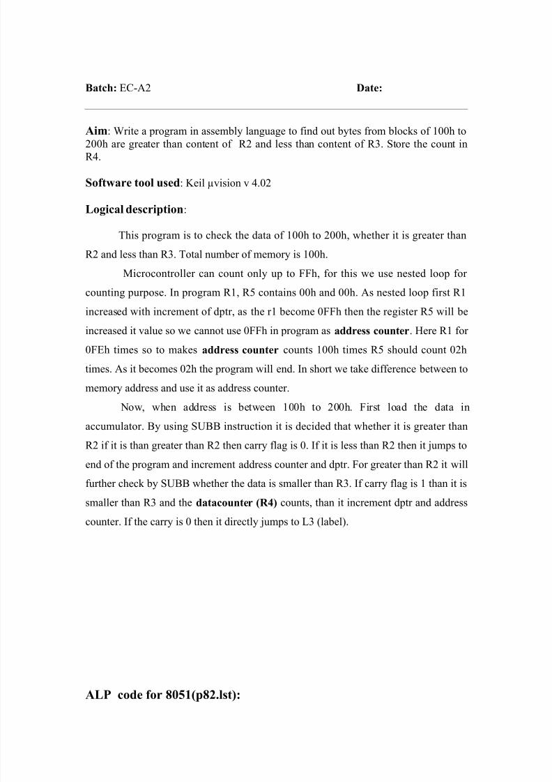
Batch: EC-A2 Date:
Aim: Write a program in assembly language to find out bytes from blocks of 100h to
200h are greater than content of R2 and less than content of R3. Store the count in
R4.
Software tool used: Keil µvision v 4.02
Logical description:
This program is to check the data of 100h to 200h, whether it is greater than
R2 and less than R3. Total number of memory is 100h.
Microcontroller can count only up to FFh, for this we use nested loop for
counting purpose. In program R1, R5 contains 00h and 00h. As nested loop first R1
increased with increment of dptr, as the r1 become 0FFh then the register R5 will be
increased it value so we cannot use 0FFh in program as address counter. Here R1 for
0FEh times so to makes address counter counts 100h times R5 should count 02h
times. As it becomes 02h the program will end. In short we take difference between to
memory address and use it as address counter.
Now, when address is between 100h to 200h. First load the data inaccumulator. By using SUBB instruction it is decided that whether it is greater than
R2 if it is than greater than R2 then carry flag is 0. If it is less than R2 then it jumps to
end of the program and increment address counter and dptr. For greater than R2 it will
further check by SUBB whether the data is smaller than R3. If carry flag is 1 than it is
smaller than R3 and the datacounter (R4) counts, than it increment dptr and address
counter. If the carry is 0 then it directly jumps to L3 (label).
ALP code for 8051(p82.lst):
8/3/2019 Micro Controller File
http://slidepdf.com/reader/full/micro-controller-file 22/50
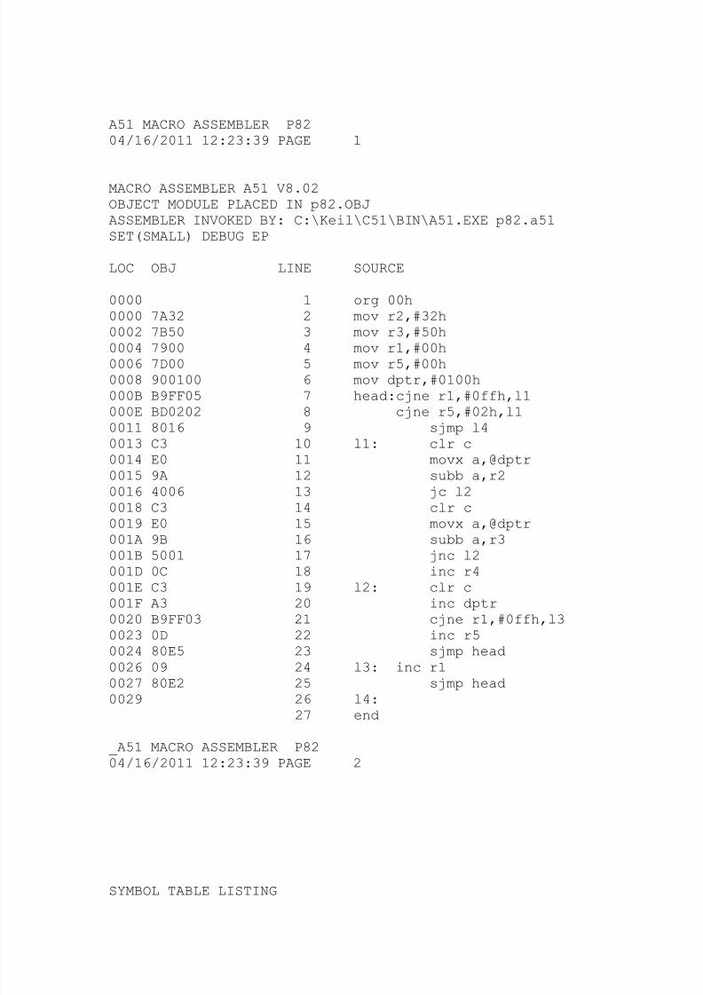
A51 MACRO ASSEMBLER P8204/16/2011 12:23:39 PAGE 1
MACRO ASSEMBLER A51 V8.02OBJECT MODULE PLACED IN p82.OBJASSEMBLER INVOKED BY: C:\Keil\C51\BIN\A51.EXE p82.a51SET(SMALL) DEBUG EP
LOC OBJ LINE SOURCE
0000 1 org 00h0000 7A32 2 mov r2,#32h0002 7B50 3 mov r3,#50h
0004 7900 4 mov r1,#00h0006 7D00 5 mov r5,#00h0008 900100 6 mov dptr,#0100h000B B9FF05 7 head:cjne r1,#0ffh,l1000E BD0202 8 cjne r5,#02h,l10011 8016 9 sjmp l40013 C3 10 l1: clr c0014 E0 11 movx a,@dptr0015 9A 12 subb a,r20016 4006 13 jc l20018 C3 14 clr c
0019 E0 15 movx a,@dptr001A 9B 16 subb a,r3001B 5001 17 jnc l2001D 0C 18 inc r4001E C3 19 l2: clr c001F A3 20 inc dptr0020 B9FF03 21 cjne r1,#0ffh,l30023 0D 22 inc r50024 80E5 23 sjmp head0026 09 24 l3: inc r10027 80E2 25 sjmp head
0029 26 l4:27 end
_A51 MACRO ASSEMBLER P8204/16/2011 12:23:39 PAGE 2
SYMBOL TABLE LISTING
8/3/2019 Micro Controller File
http://slidepdf.com/reader/full/micro-controller-file 23/50
------ ----- -------
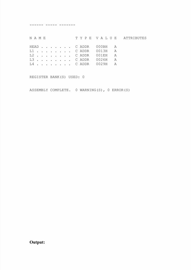
N A M E T Y P E V A L U E ATTRIBUTES
HEAD . . . . . . . C ADDR 000BH AL1 . . . . . . . . C ADDR 0013H AL2 . . . . . . . . C ADDR 001EH AL3 . . . . . . . . C ADDR 0026H AL4 . . . . . . . . C ADDR 0029H A
REGISTER BANK(S) USED: 0
ASSEMBLY COMPLETE. 0 WARNING(S), 0 ERROR(S)
Output:
8/3/2019 Micro Controller File
http://slidepdf.com/reader/full/micro-controller-file 24/50
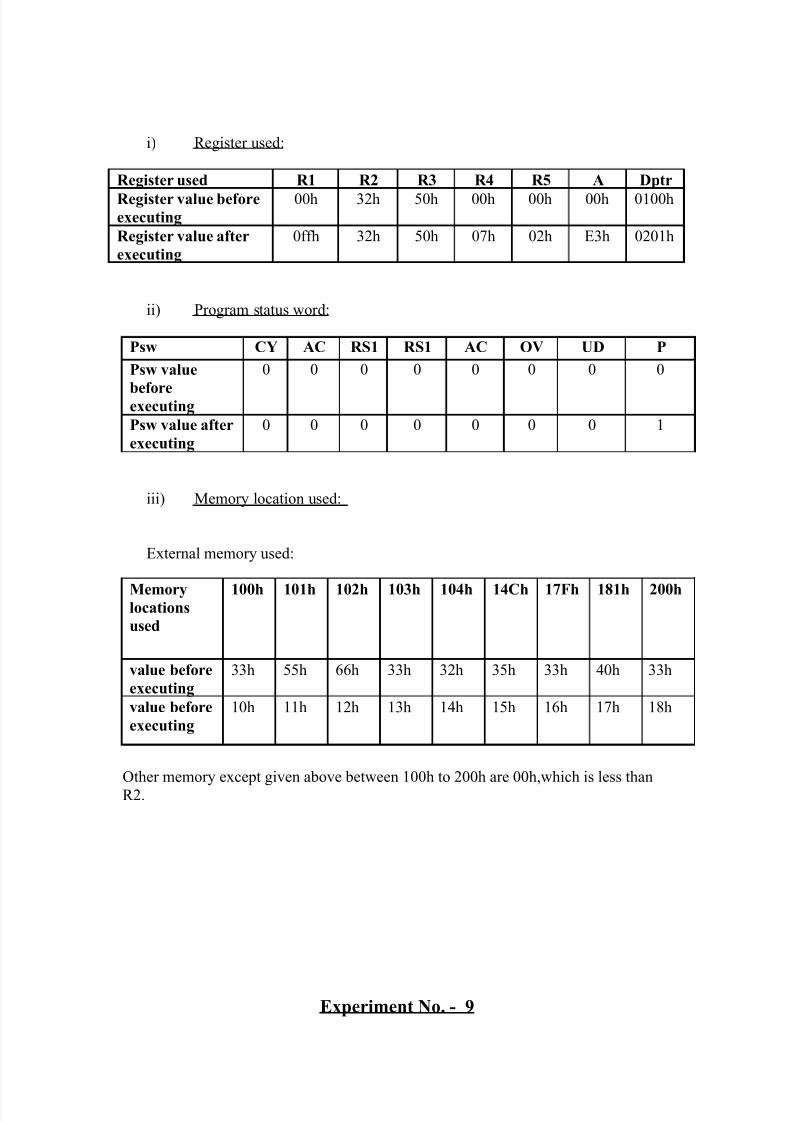
i) Register used:
Register used R1 R2 R3 R4 R5 A Dptr
Register value beforeexecuting
00h 32h 50h 00h 00h 00h 0100h
Register value after
executing
0ffh 32h 50h 07h 02h E3h 0201h
ii) Program status word:
Psw CY AC RS1 RS1 AC OV UD P
Psw value
beforeexecuting
0 0 0 0 0 0 0 0
Psw value after
executing
0 0 0 0 0 0 0 1
iii) Memory location used:
External memory used:
Other memory except given above between 100h to 200h are 00h,which is less than
R2.
Experiment No. - 9
Memorylocations
used
100h 101h 102h 103h 104h 14Ch 17Fh 181h 200h
value before
executing
33h 55h 66h 33h 32h 35h 33h 40h 33h
value before
executing
10h 11h 12h 13h 14h 15h 16h 17h 18h
8/3/2019 Micro Controller File
http://slidepdf.com/reader/full/micro-controller-file 25/50
Batch: EC-A2 Date:
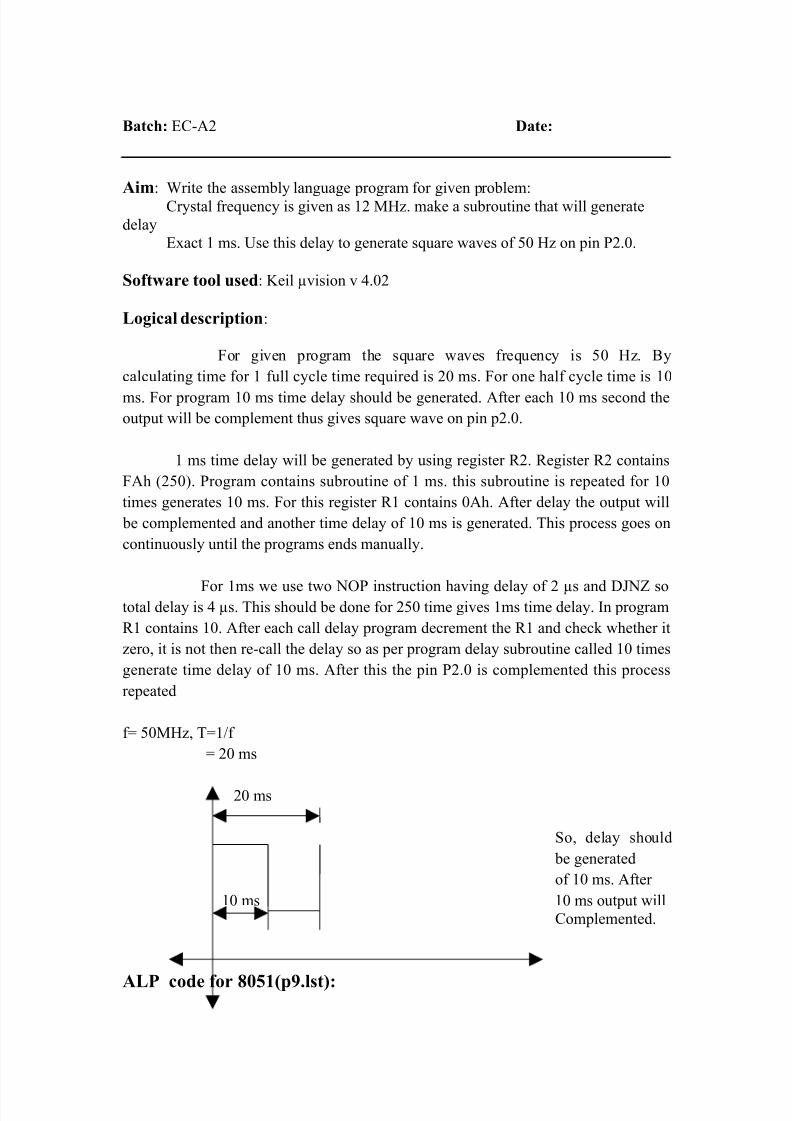
Aim: Write the assembly language program for given problem:
Crystal frequency is given as 12 MHz. make a subroutine that will generate
delay
Exact 1 ms. Use this delay to generate square waves of 50 Hz on pin P2.0.
Software tool used: Keil µvision v 4.02
Logical description:
For given program the square waves frequency is 50 Hz. By
calculating time for 1 full cycle time required is 20 ms. For one half cycle time is 10
ms. For program 10 ms time delay should be generated. After each 10 ms second the
output will be complement thus gives square wave on pin p2.0.
1 ms time delay will be generated by using register R2. Register R2 contains
FAh (250). Program contains subroutine of 1 ms. this subroutine is repeated for 10
times generates 10 ms. For this register R1 contains 0Ah. After delay the output will
be complemented and another time delay of 10 ms is generated. This process goes on
continuously until the programs ends manually.
For 1ms we use two NOP instruction having delay of 2 µs and DJNZ sototal delay is 4 µs. This should be done for 250 time gives 1ms time delay. In program
R1 contains 10. After each call delay program decrement the R1 and check whether it
zero, it is not then re-call the delay so as per program delay subroutine called 10 times
generate time delay of 10 ms. After this the pin P2.0 is complemented this process
repeated
f= 50MHz, T=1/f
= 20 ms
20 ms
So, delay should
be generated
of 10 ms. After
10 ms 10 ms output will
Complemented.
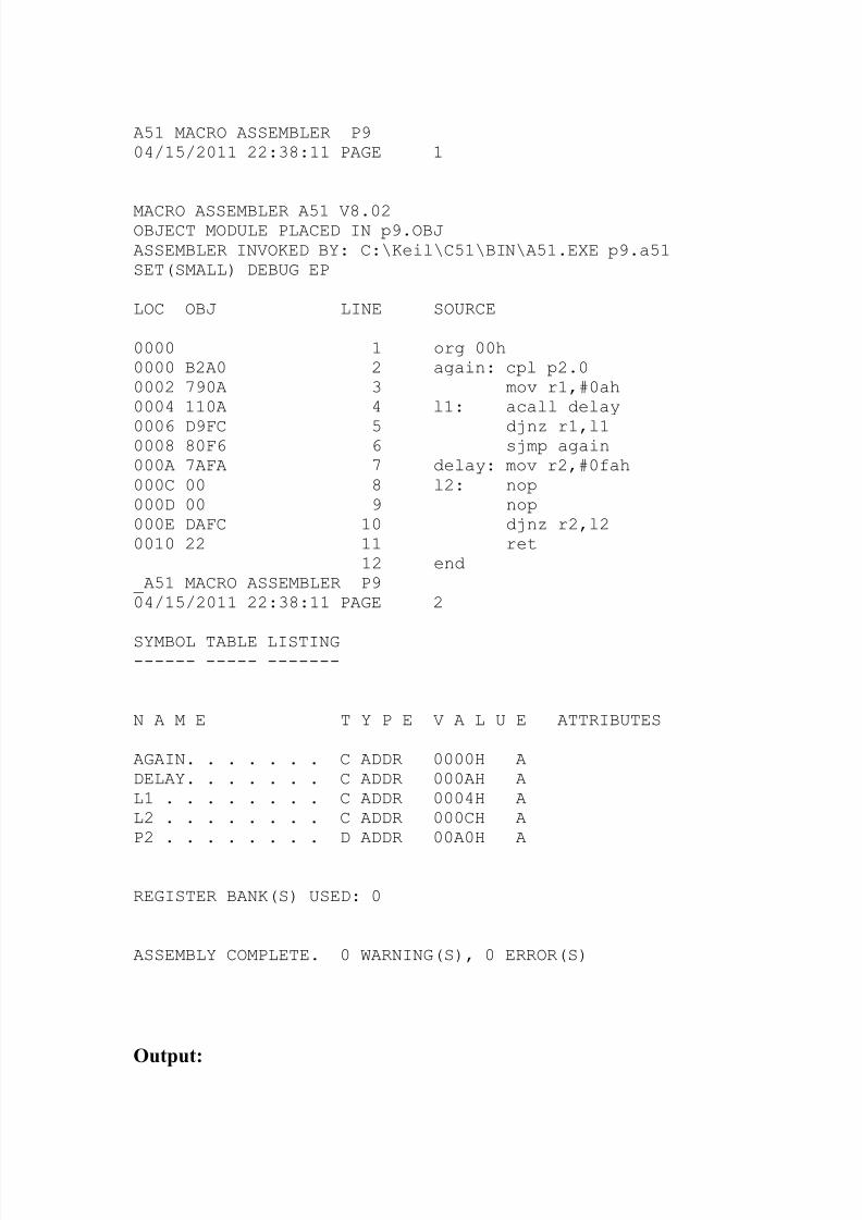
ALP code for 8051(p9.lst):
8/3/2019 Micro Controller File
http://slidepdf.com/reader/full/micro-controller-file 26/50
A51 MACRO ASSEMBLER P904/15/2011 22:38:11 PAGE 1
MACRO ASSEMBLER A51 V8.02OBJECT MODULE PLACED IN p9.OBJASSEMBLER INVOKED BY: C:\Keil\C51\BIN\A51.EXE p9.a51SET(SMALL) DEBUG EP
LOC OBJ LINE SOURCE
0000 1 org 00h0000 B2A0 2 again: cpl p2.00002 790A 3 mov r1,#0ah0004 110A 4 l1: acall delay
0006 D9FC 5 djnz r1,l10008 80F6 6 sjmp again000A 7AFA 7 delay: mov r2,#0fah000C 00 8 l2: nop000D 00 9 nop000E DAFC 10 djnz r2,l20010 22 11 ret
12 end_A51 MACRO ASSEMBLER P904/15/2011 22:38:11 PAGE 2
SYMBOL TABLE LISTING------ ----- -------
N A M E T Y P E V A L U E ATTRIBUTES
AGAIN. . . . . . . C ADDR 0000H ADELAY. . . . . . . C ADDR 000AH AL1 . . . . . . . . C ADDR 0004H AL2 . . . . . . . . C ADDR 000CH AP2 . . . . . . . . D ADDR 00A0H A
REGISTER BANK(S) USED: 0
ASSEMBLY COMPLETE. 0 WARNING(S), 0 ERROR(S)
Output:
8/3/2019 Micro Controller File
http://slidepdf.com/reader/full/micro-controller-file 27/50
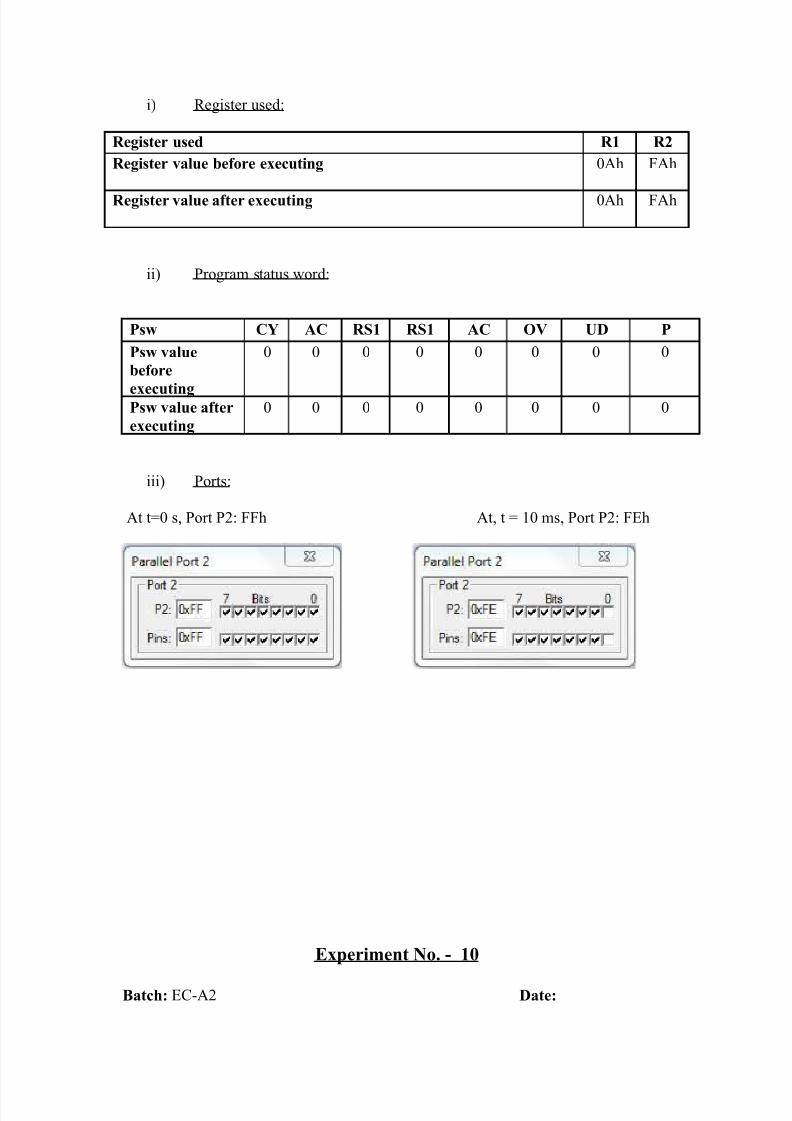
i) Register used:
Register used R1 R2
Register value before executing 0Ah FAh
Register value after executing 0Ah FAh
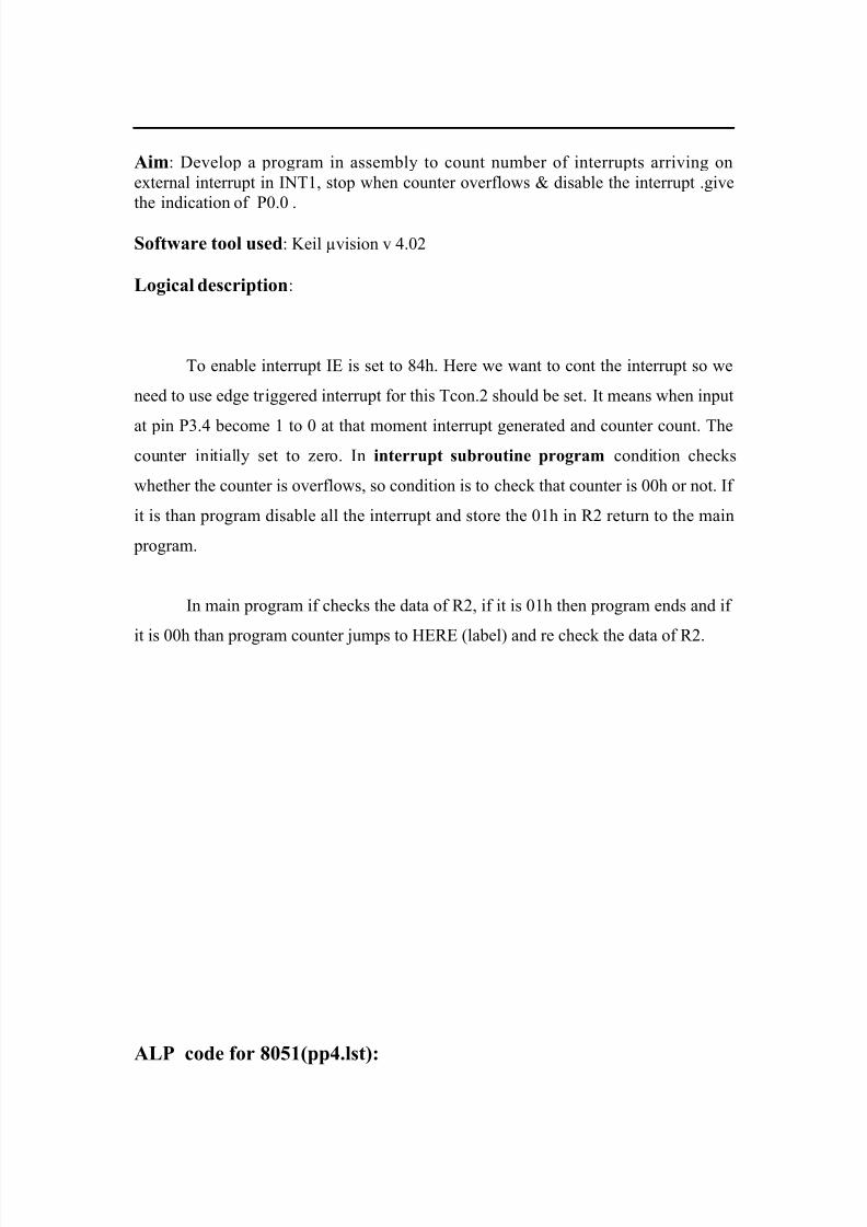
ii) Program status word:
Psw CY AC RS1 RS1 AC OV UD P
Psw value
before
executing
0 0 0 0 0 0 0 0
Psw value after
executing
0 0 0 0 0 0 0 0
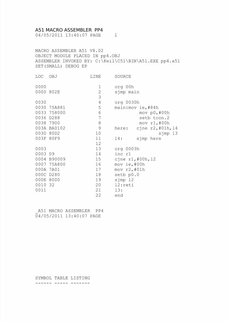
iii) Ports:
At t=0 s, Port P2: FFh At, t = 10 ms, Port P2: FEh
Experiment No. - 10
Batch: EC-A2 Date:
8/3/2019 Micro Controller File
http://slidepdf.com/reader/full/micro-controller-file 28/50
Aim: Develop a program in assembly to count number of interrupts arriving on
external interrupt in INT1, stop when counter overflows & disable the interrupt .give
the indication of P0.0 .
Software tool used: Keil µvision v 4.02
Logical description:
To enable interrupt IE is set to 84h. Here we want to cont the interrupt so we
need to use edge triggered interrupt for this Tcon.2 should be set. It means when input
at pin P3.4 become 1 to 0 at that moment interrupt generated and counter count. Thecounter initially set to zero. In interrupt subroutine program condition checks
whether the counter is overflows, so condition is to check that counter is 00h or not. If
it is than program disable all the interrupt and store the 01h in R2 return to the main
program.
In main program if checks the data of R2, if it is 01h then program ends and if
it is 00h than program counter jumps to HERE (label) and re check the data of R2.
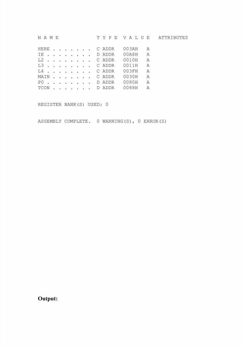
ALP code for 8051(pp4.lst):
8/3/2019 Micro Controller File
http://slidepdf.com/reader/full/micro-controller-file 29/50
A51 MACRO ASSEMBLER PP4
04/05/2011 13:40:07 PAGE 1
MACRO ASSEMBLER A51 V8.02
OBJECT MODULE PLACED IN pp4.OBJASSEMBLER INVOKED BY: C:\Keil\C51\BIN\A51.EXE pp4.a51SET(SMALL) DEBUG EP
LOC OBJ LINE SOURCE
0000 1 org 00h0000 802E 2 sjmp main
30030 4 org 0030h0030 75A881 5 main:mov ie,#84h
0033 758000 6 mov p0,#00h0036 D288 7 setb tcon.20038 7900 8 mov r1,#00h003A BA0102 9 here: cjne r2,#01h,l4003D 80D2 10 sjmp l3003F 80F9 11 l4: sjmp here
120003 13 org 0003h0003 09 14 inc r10004 B90009 15 cjne r1,#00h,l20007 75A800 16 mov ie,#00h
000A 7A01 17 mov r2,#01h000C D280 18 setb p0.0000E 8000 19 sjmp l20010 32 20 l2:reti0011 21 l3:
22 end
_A51 MACRO ASSEMBLER PP404/05/2011 13:40:07 PAGE
SYMBOL TABLE LISTING
------ ----- -------
8/3/2019 Micro Controller File
http://slidepdf.com/reader/full/micro-controller-file 30/50
N A M E T Y P E V A L U E ATTRIBUTES
HERE . . . . . . . C ADDR 003AH AIE . . . . . . . . D ADDR 00A8H A
L2 . . . . . . . . C ADDR 0010H AL3 . . . . . . . . C ADDR 0011H AL4 . . . . . . . . C ADDR 003FH AMAIN . . . . . . . C ADDR 0030H AP0 . . . . . . . . D ADDR 0080H ATCON . . . . . . . D ADDR 0088H A
REGISTER BANK(S) USED: 0
ASSEMBLY COMPLETE. 0 WARNING(S), 0 ERROR(S)
Output:
8/3/2019 Micro Controller File
http://slidepdf.com/reader/full/micro-controller-file 31/50
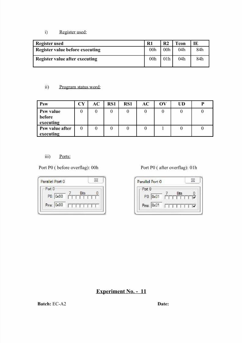
i) Register used:
Register used R1 R2 Tcon IE
Register value before executing 00h 00h 04h 84h
Register value after executing 00h 01h 04h 84h
ii) Program status word:
Psw CY AC RS1 RS1 AC OV UD P
Psw value
before
executing
0 0 0 0 0 0 0 0
Psw value after
executing
0 0 0 0 0 1 0 0
iii) Ports:
Port P0 ( before overflag): 00h Port P0 ( after overflag): 01h
Experiment No. - 11
Batch: EC-A2 Date:
8/3/2019 Micro Controller File
http://slidepdf.com/reader/full/micro-controller-file 32/50
Aim: Write a assembly language program to continuously scan port p0 if data is other
than FFh write a subroutine that will multiply it with 10d and send it to port P1,P2.
Software tool used: Keil µvision v 4.02
Logical description:
As per our program we have to check the port P0 continuously by looping
when the data do not equal to the FFh then call function call the subroutine that will
multiply the term of port P0 with 10d. In this MUL AB instruction is used the last 8
bit data is stored in register A and another 8 bit data are in register B.
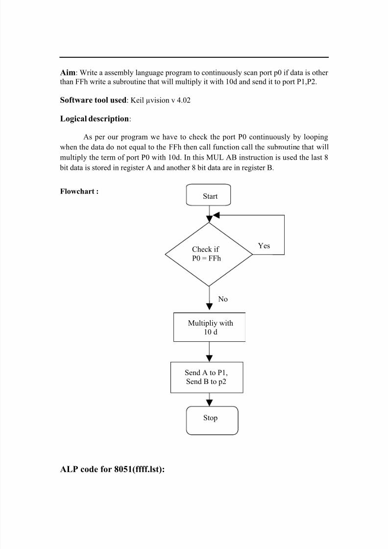
Flowchart :
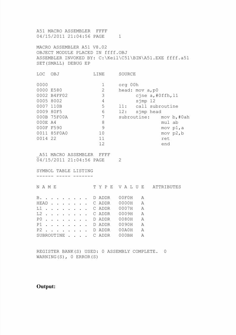
ALP code for 8051(ffff.lst):
Start
Check if
P0 = FFh
Multipliy with
10 d
Send A to P1,
Send B to p2
Stop
No
Yes
8/3/2019 Micro Controller File
http://slidepdf.com/reader/full/micro-controller-file 33/50
A51 MACRO ASSEMBLER FFFF04/15/2011 21:04:56 PAGE 1
MACRO ASSEMBLER A51 V8.02OBJECT MODULE PLACED IN ffff.OBJ
ASSEMBLER INVOKED BY: C:\Keil\C51\BIN\A51.EXE ffff.a51SET(SMALL) DEBUG EP
LOC OBJ LINE SOURCE
0000 1 org 00h0000 E580 2 head: mov a,p00002 B4FF02 3 cjne a,#0ffh,l10005 8002 4 sjmp l20007 110B 5 l1: call subroutine0009 80F5 6 l2: sjmp head
000B 75F00A 7 subroutine: mov b,#0ah000E A4 8 mul ab000F F590 9 mov p1,a0011 85F0A0 10 mov p2,b0014 22 11 ret
12 end _A51 MACRO ASSEMBLER FFFF04/15/2011 21:04:56 PAGE 2
SYMBOL TABLE LISTING
------ ----- -------
N A M E T Y P E V A L U E ATTRIBUTES
B. . . . . . . . . D ADDR 00F0H AHEAD . . . . . . . C ADDR 0000H AL1 . . . . . . . . C ADDR 0007H AL2 . . . . . . . . C ADDR 0009H AP0 . . . . . . . . D ADDR 0080H AP1 . . . . . . . . D ADDR 0090H AP2 . . . . . . . . D ADDR 00A0H A
SUBROUTINE . . . . C ADDR 000BH A
REGISTER BANK(S) USED: 0 ASSEMBLY COMPLETE. 0WARNING(S), 0 ERROR(S)
Output:
8/3/2019 Micro Controller File
http://slidepdf.com/reader/full/micro-controller-file 34/50
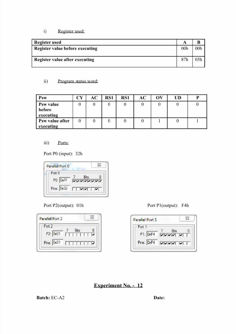
i) Register used:
Register used A B
Register value before executing 00h 00h
Register value after executing 87h 05h
ii) Program status word:
Psw CY AC RS1 RS1 AC OV UD P
Psw value
before
executing
0 0 0 0 0 0 0 0
Psw value after
executing
0 0 0 0 0 1 0 1
iii) Ports:
Port P0 (input): 32h
Port P2(output): 01h Port P1(output): F4h
Experiment No. - 12
Batch: EC-A2 Date:
8/3/2019 Micro Controller File
http://slidepdf.com/reader/full/micro-controller-file 35/50
Aim: write a assembly language program to generate a delay of 500 ms using
software instruction.
Software tool used: Keil µvision v 4.02
Logical description:
By using software instruction we can generate time delay by using register
changing the value and waste the time of microcontroller to get the desired delay. We
can use NOP to waste time of microcontroller.
Here we use main program portion having time delay of 1 ms which is
repeated by 500 time to generate time delay of 500 ms. Register R2 contains FAh(250) to generate the time delay of 1 ms. The other register R1 contains FAh (250). So
the 1 ms time delay generated for 250 times generates 250 ms and the last register R0
contain 02h which generate delay of 250 ms for 2 times gives total time delay of 500
ms.
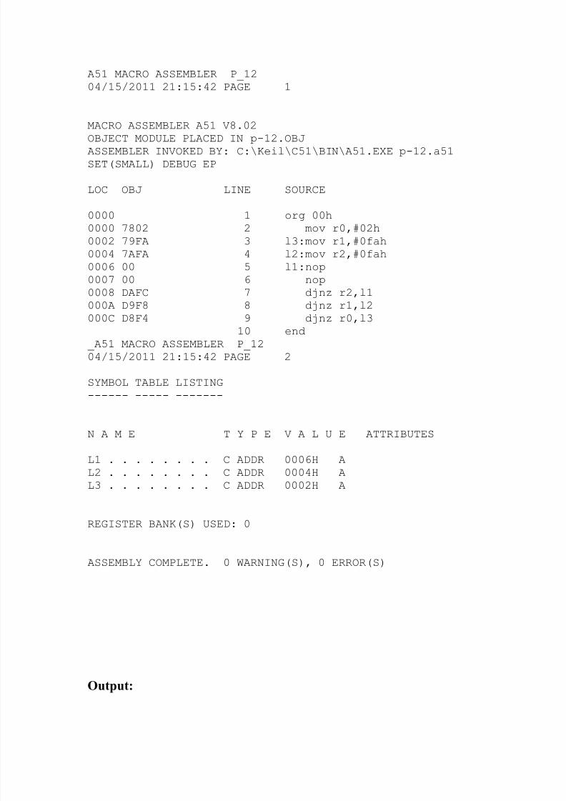
ALP code for 8051(p-12.lst):
8/3/2019 Micro Controller File
http://slidepdf.com/reader/full/micro-controller-file 36/50
A51 MACRO ASSEMBLER P_1204/15/2011 21:15:42 PAGE 1
MACRO ASSEMBLER A51 V8.02
OBJECT MODULE PLACED IN p-12.OBJASSEMBLER INVOKED BY: C:\Keil\C51\BIN\A51.EXE p-12.a51SET(SMALL) DEBUG EP
LOC OBJ LINE SOURCE
0000 1 org 00h0000 7802 2 mov r0,#02h0002 79FA 3 l3:mov r1,#0fah0004 7AFA 4 l2:mov r2,#0fah0006 00 5 l1:nop
0007 00 6 nop0008 DAFC 7 djnz r2,l1000A D9F8 8 djnz r1,l2000C D8F4 9 djnz r0,l3
10 end_A51 MACRO ASSEMBLER P_1204/15/2011 21:15:42 PAGE 2
SYMBOL TABLE LISTING------ ----- -------
N A M E T Y P E V A L U E ATTRIBUTES
L1 . . . . . . . . C ADDR 0006H AL2 . . . . . . . . C ADDR 0004H AL3 . . . . . . . . C ADDR 0002H A
REGISTER BANK(S) USED: 0
ASSEMBLY COMPLETE. 0 WARNING(S), 0 ERROR(S)
Output:
8/3/2019 Micro Controller File
http://slidepdf.com/reader/full/micro-controller-file 37/50
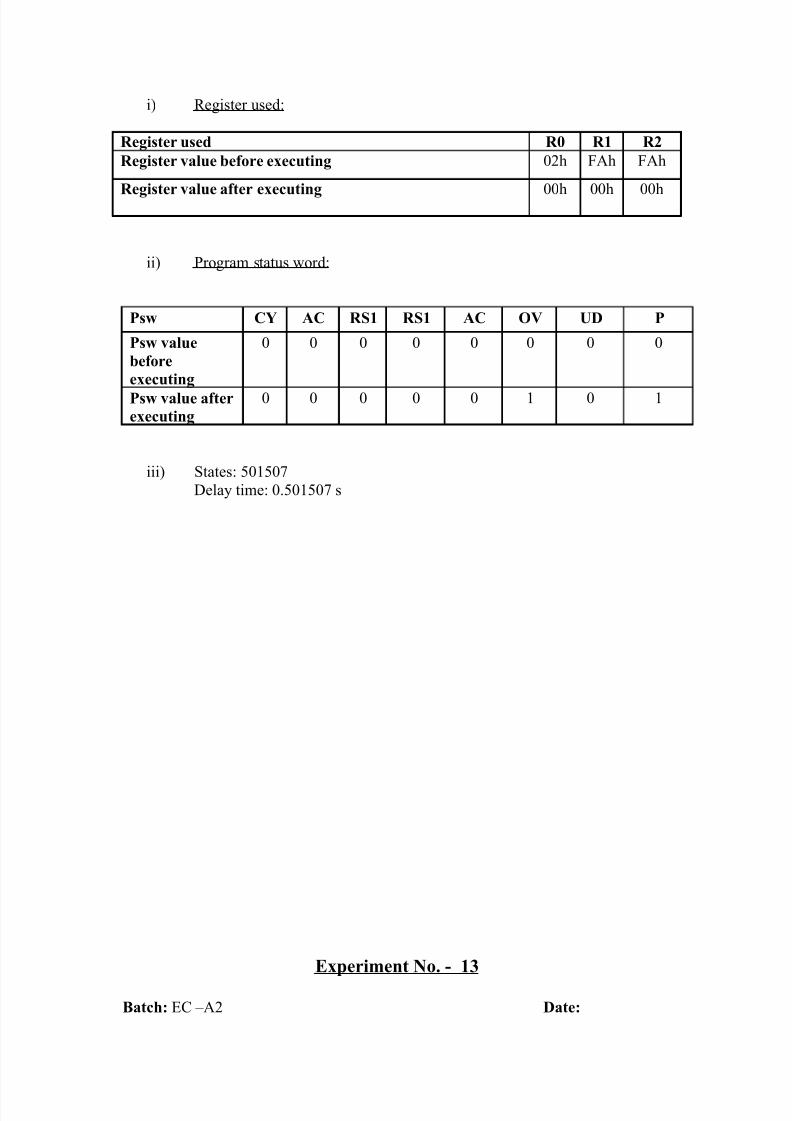
i) Register used:
Register used R0 R1 R2
Register value before executing 02h FAh FAh
Register value after executing 00h 00h 00h
ii) Program status word:
Psw CY AC RS1 RS1 AC OV UD P
Psw value
before
executing
0 0 0 0 0 0 0 0
Psw value afterexecuting
0 0 0 0 0 1 0 1
iii) States: 501507
Delay time: 0.501507 s
Experiment No. - 13
Batch: EC –A2 Date:
8/3/2019 Micro Controller File
http://slidepdf.com/reader/full/micro-controller-file 38/50
Aim: Generate the delay of 500ms using timer 0 in mode 1 (frequency 11.059 MHz).
Software tool used: Keil µvision v 4.02
Logical description:
As per our problem we have to generate the time delay of 500 ms second
using timer0 in mode 1.we have clock frequency of 11.059 Hz so as per calculation of
time for one machine cycle is 1.085 µs, so we can get maximum time delay by timer
is 65536*1.085 µs = 71.10 ms, So we have to repeat the timer 500/71.10 = 7.03 is
approximately 7 times. That gives us time delay of 499.9 ms.
Calculation:
ALP code for 8051(pp5.lst):
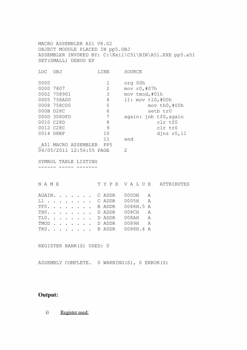
A51 MACRO ASSEMBLER PP504/05/2011 12:56:55 PAGE 1
8/3/2019 Micro Controller File
http://slidepdf.com/reader/full/micro-controller-file 39/50
MACRO ASSEMBLER A51 V8.02OBJECT MODULE PLACED IN pp5.OBJASSEMBLER INVOKED BY: C:\Keil\C51\BIN\A51.EXE pp5.a51
SET(SMALL) DEBUG EP
LOC OBJ LINE SOURCE
0000 1 org 00h0000 7807 2 mov r0,#07h0002 758901 3 mov tmod,#01h0005 758A00 4 l1: mov tl0,#00h0008 758C00 5 mov th0,#00h000B D28C 6 setb tr0000D 308DFD 7 again: jnb tf0,again
0010 C28D 8 clr tf00012 C28C 9 clr tr00014 D8EF 10 djnz r0,l1
11 end_A51 MACRO ASSEMBLER PP504/05/2011 12:56:55 PAGE 2
SYMBOL TABLE LISTING------ ----- -------
N A M E T Y P E V A L U E ATTRIBUTES
AGAIN. . . . . . . C ADDR 000DH AL1 . . . . . . . . C ADDR 0005H ATF0. . . . . . . . B ADDR 0088H.5 ATH0. . . . . . . . D ADDR 008CH ATL0. . . . . . . . D ADDR 008AH ATMOD . . . . . . . D ADDR 0089H ATR0. . . . . . . . B ADDR 0088H.4 A
REGISTER BANK(S) USED: 0
ASSEMBLY COMPLETE. 0 WARNING(S), 0 ERROR(S)
Output:
i) Register used:
8/3/2019 Micro Controller File
http://slidepdf.com/reader/full/micro-controller-file 40/50
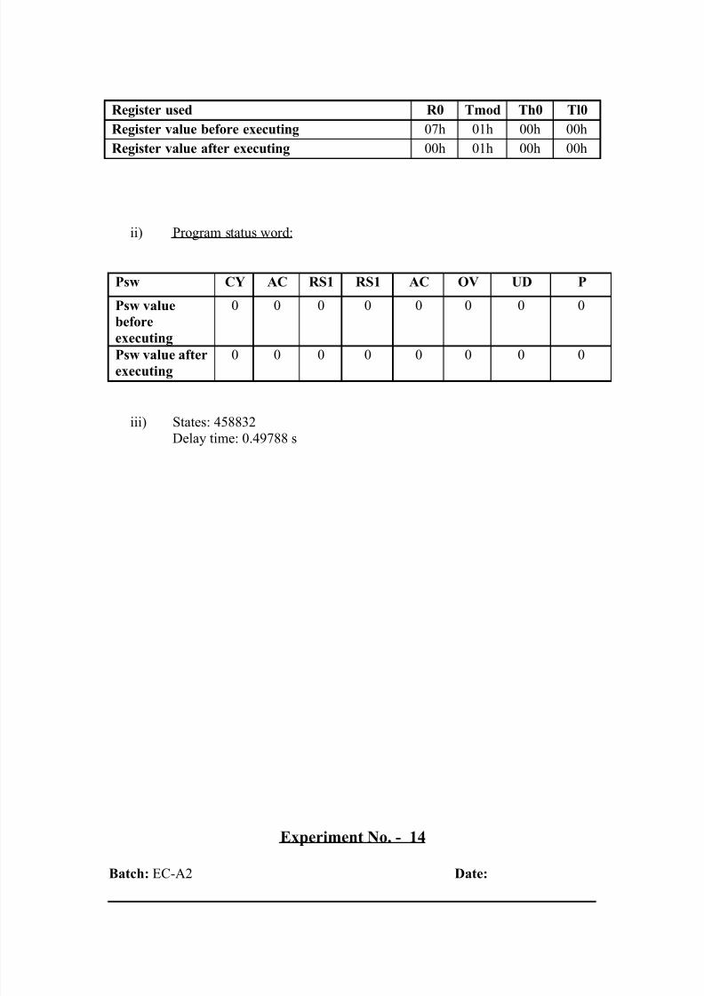
Register used R0 Tmod Th0 Tl0
Register value before executing 07h 01h 00h 00h
Register value after executing 00h 01h 00h 00h
ii) Program status word:
Psw CY AC RS1 RS1 AC OV UD P
Psw value
before
executing
0 0 0 0 0 0 0 0
Psw value after
executing
0 0 0 0 0 0 0 0
iii) States: 458832
Delay time: 0.49788 s
Experiment No. - 14
Batch: EC-A2 Date:
8/3/2019 Micro Controller File
http://slidepdf.com/reader/full/micro-controller-file 41/50
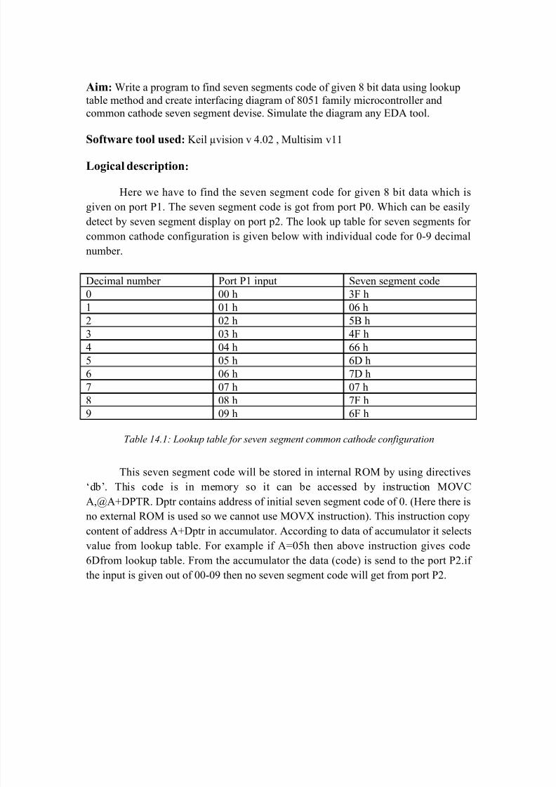
Aim: Write a program to find seven segments code of given 8 bit data using lookup
table method and create interfacing diagram of 8051 family microcontroller and
common cathode seven segment devise. Simulate the diagram any EDA tool.
Software tool used: Keil µvision v 4.02 , Multisim v11
Logical description:
Here we have to find the seven segment code for given 8 bit data which is
given on port P1. The seven segment code is got from port P0. Which can be easily
detect by seven segment display on port p2. The look up table for seven segments for
common cathode configuration is given below with individual code for 0-9 decimal
number.
Decimal number Port P1 input Seven segment code
0 00 h 3F h
1 01 h 06 h
2 02 h 5B h
3 03 h 4F h
4 04 h 66 h
5 05 h 6D h
6 06 h 7D h
7 07 h 07 h
8 08 h 7F h
9 09 h 6F h
Table 14.1: Lookup table for seven segment common cathode configuration
This seven segment code will be stored in internal ROM by using directives
‘db’. This code is in memory so it can be accessed by instruction MOVC
A,@A+DPTR. Dptr contains address of initial seven segment code of 0. (Here there is
no external ROM is used so we cannot use MOVX instruction). This instruction copy
content of address A+Dptr in accumulator. According to data of accumulator it selects
value from lookup table. For example if A=05h then above instruction gives code
6Dfrom lookup table. From the accumulator the data (code) is send to the port P2.if
the input is given out of 00-09 then no seven segment code will get from port P2.
8/3/2019 Micro Controller File
http://slidepdf.com/reader/full/micro-controller-file 42/50
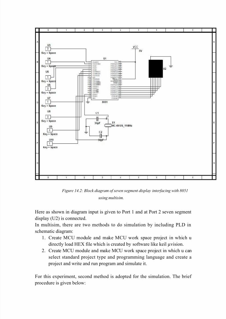
Figure 14.2: Block diagram of seven segment display interfacing with 8051
using multisim.
Here as shown in diagram input is given to Port 1 and at Port 2 seven segment
display (U2) is connected.
In multisim, there are two methods to do simulation by including PLD in
schematic diagram:
1. Create MCU module and make MCU work space project in which u
directly load HEX file which is created by software like keil µvision.
2. Create MCU module and make MCU work space project in which u can
select standard project type and programming language and create a
project and write and run program and simulate it.
For this experiment, second method is adopted for the simulation. The brief
procedure is given below:
8/3/2019 Micro Controller File
http://slidepdf.com/reader/full/micro-controller-file 43/50
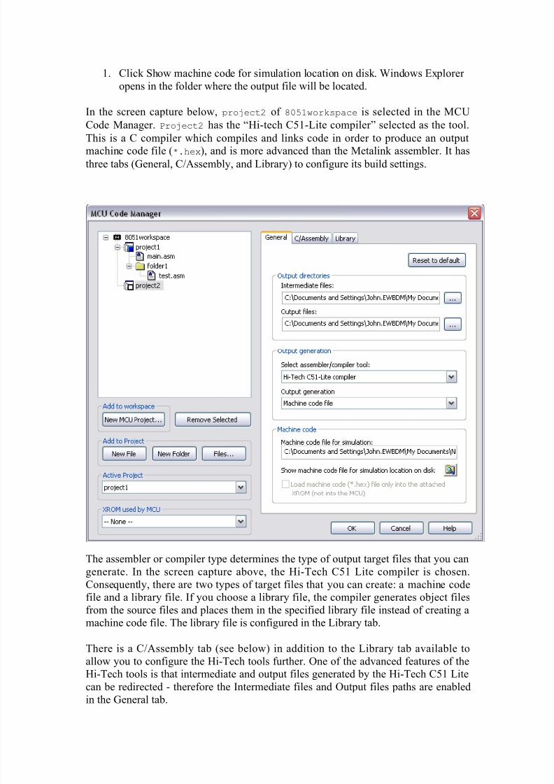
1. Click Show machine code for simulation location on disk. Windows Explorer
opens in the folder where the output file will be located.
In the screen capture below, project2 of 8051workspace is selected in the MCU
Code Manager. Project2 has the “Hi-tech C51-Lite compiler” selected as the tool.
This is a C compiler which compiles and links code in order to produce an outputmachine code file (*.hex), and is more advanced than the Metalink assembler. It has
three tabs (General, C/Assembly, and Library) to configure its build settings.
The assembler or compiler type determines the type of output target files that you can
generate. In the screen capture above, the Hi-Tech C51 Lite compiler is chosen.
Consequently, there are two types of target files that you can create: a machine code
file and a library file. If you choose a library file, the compiler generates object files
from the source files and places them in the specified library file instead of creating a
machine code file. The library file is configured in the Library tab.
There is a C/Assembly tab (see below) in addition to the Library tab available to
allow you to configure the Hi-Tech tools further. One of the advanced features of the
Hi-Tech tools is that intermediate and output files generated by the Hi-Tech C51 Lite
can be redirected - therefore the Intermediate files and Output files paths are enabledin the General tab.
8/3/2019 Micro Controller File
http://slidepdf.com/reader/full/micro-controller-file 44/50
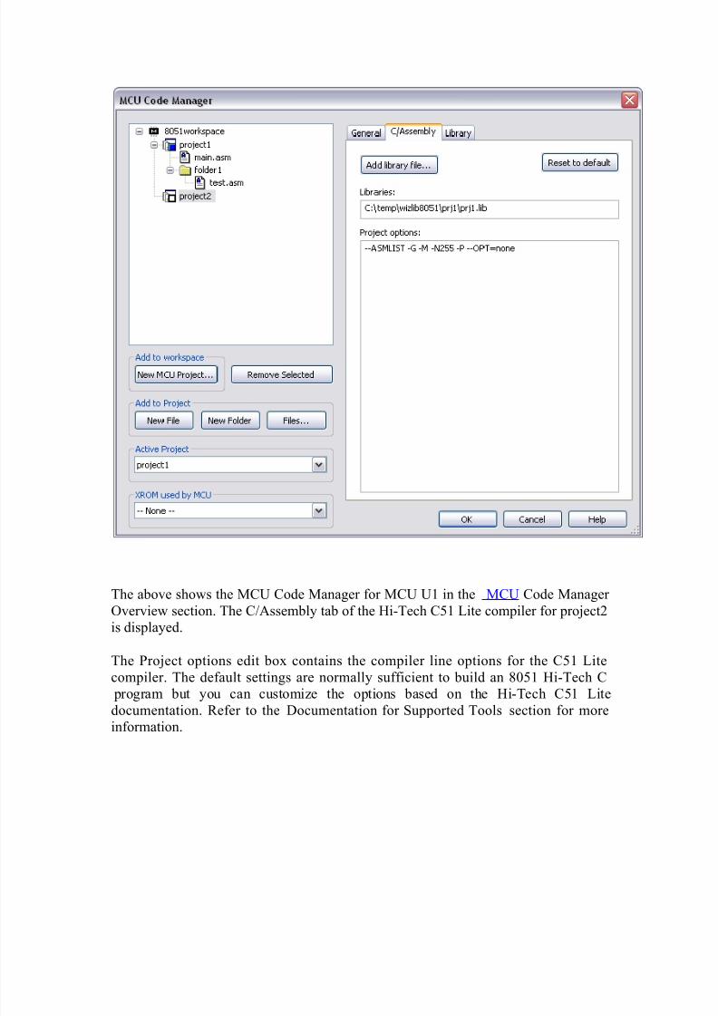
The above shows the MCU Code Manager for MCU U1 in the MCU Code Manager
Overview section. The C/Assembly tab of the Hi-Tech C51 Lite compiler for project2
is displayed.
The Project options edit box contains the compiler line options for the C51 Lite
compiler. The default settings are normally sufficient to build an 8051 Hi-Tech C
program but you can customize the options based on the Hi-Tech C51 Lite
documentation. Refer to the Documentation for Supported Tools section for moreinformation.
8/3/2019 Micro Controller File
http://slidepdf.com/reader/full/micro-controller-file 45/50
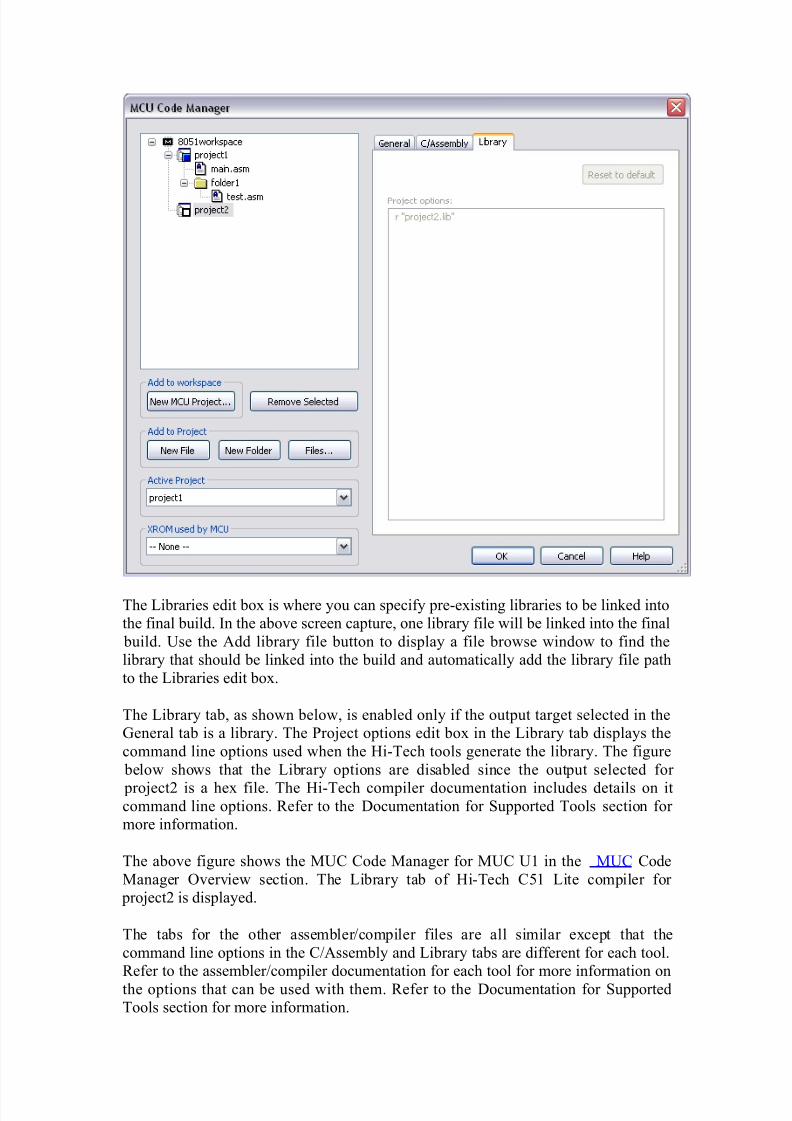
The Libraries edit box is where you can specify pre-existing libraries to be linked into
the final build. In the above screen capture, one library file will be linked into the final
build. Use the Add library file button to display a file browse window to find the
library that should be linked into the build and automatically add the library file path
to the Libraries edit box.
The Library tab, as shown below, is enabled only if the output target selected in the
General tab is a library. The Project options edit box in the Library tab displays the
command line options used when the Hi-Tech tools generate the library. The figure
below shows that the Library options are disabled since the output selected for
project2 is a hex file. The Hi-Tech compiler documentation includes details on itcommand line options. Refer to the Documentation for Supported Tools section for
more information.
The above figure shows the MUC Code Manager for MUC U1 in the MUC Code
Manager Overview section. The Library tab of Hi-Tech C51 Lite compiler for
project2 is displayed.
The tabs for the other assembler/compiler files are all similar except that the
command line options in the C/Assembly and Library tabs are different for each tool.
Refer to the assembler/compiler documentation for each tool for more information on
the options that can be used with them. Refer to the Documentation for Supported
Tools section for more information.
8/3/2019 Micro Controller File
http://slidepdf.com/reader/full/micro-controller-file 46/50
The tab that was not shown in the above example is the Link tab. The Hi-Tech
compilers have the ability to pass on the command line options to their linker tool
from the compiler. This means that the command line options for both the compiler
and the linker can be specified all at once in the command line options for the
compiler, which is when no Link tab is required.
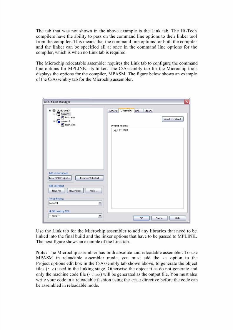
The Microchip relocatable assembler requires the Link tab to configure the command
line options for MPLINK, its linker. The C/Assembly tab for the Microchip tools
displays the options for the compiler, MPASM. The figure below shows an example
of the C/Assembly tab for the Microchip assembler.
Use the Link tab for the Microchip assembler to add any libraries that need to belinked into the final build and the linker options that have to be passed to MPLINK.
The next figure shows an example of the Link tab.
Note: The Microchip assembler has both absolute and reloadable assembler. To use
MPASM in reloadable assembler mode, you must add the /o option to the
Project options edit box in the C/Assembly tab shown above, to generate the object
files (*.o) used in the linking stage. Otherwise the object files do not generate and
only the machine code file (*.hex) will be generated as the output file. You must also
write your code in a reloadable fashion using the CODE directive before the code can
be assembled in reloadable mode.
8/3/2019 Micro Controller File
http://slidepdf.com/reader/full/micro-controller-file 47/50
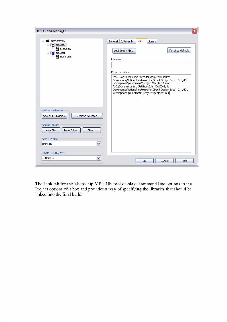
The Link tab for the Microchip MPLINK tool displays command line options in the
Project options edit box and provides a way of specifying the libraries that should be
linked into the final build.
8/3/2019 Micro Controller File
http://slidepdf.com/reader/full/micro-controller-file 48/50
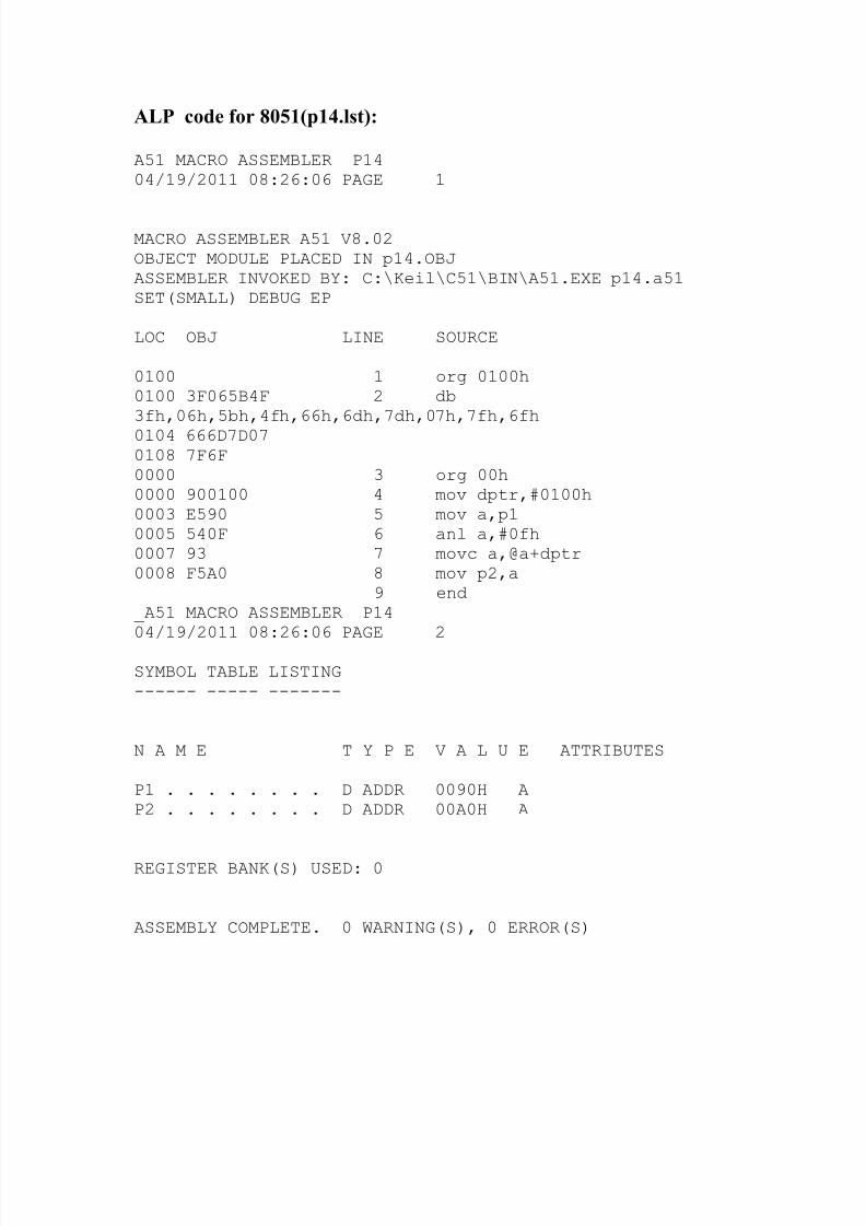
ALP code for 8051(p14.lst):
A51 MACRO ASSEMBLER P1404/19/2011 08:26:06 PAGE 1
MACRO ASSEMBLER A51 V8.02OBJECT MODULE PLACED IN p14.OBJASSEMBLER INVOKED BY: C:\Keil\C51\BIN\A51.EXE p14.a51SET(SMALL) DEBUG EP
LOC OBJ LINE SOURCE
0100 1 org 0100h0100 3F065B4F 2 db3fh,06h,5bh,4fh,66h,6dh,7dh,07h,7fh,6fh0104 666D7D070108 7F6F0000 3 org 00h0000 900100 4 mov dptr,#0100h0003 E590 5 mov a,p10005 540F 6 anl a,#0fh0007 93 7 movc a,@a+dptr0008 F5A0 8 mov p2,a
9 end_A51 MACRO ASSEMBLER P1404/19/2011 08:26:06 PAGE 2
SYMBOL TABLE LISTING------ ----- -------
N A M E T Y P E V A L U E ATTRIBUTES
P1 . . . . . . . . D ADDR 0090H AP2 . . . . . . . . D ADDR 00A0H A
REGISTER BANK(S) USED: 0
ASSEMBLY COMPLETE. 0 WARNING(S), 0 ERROR(S)
8/3/2019 Micro Controller File
http://slidepdf.com/reader/full/micro-controller-file 49/50
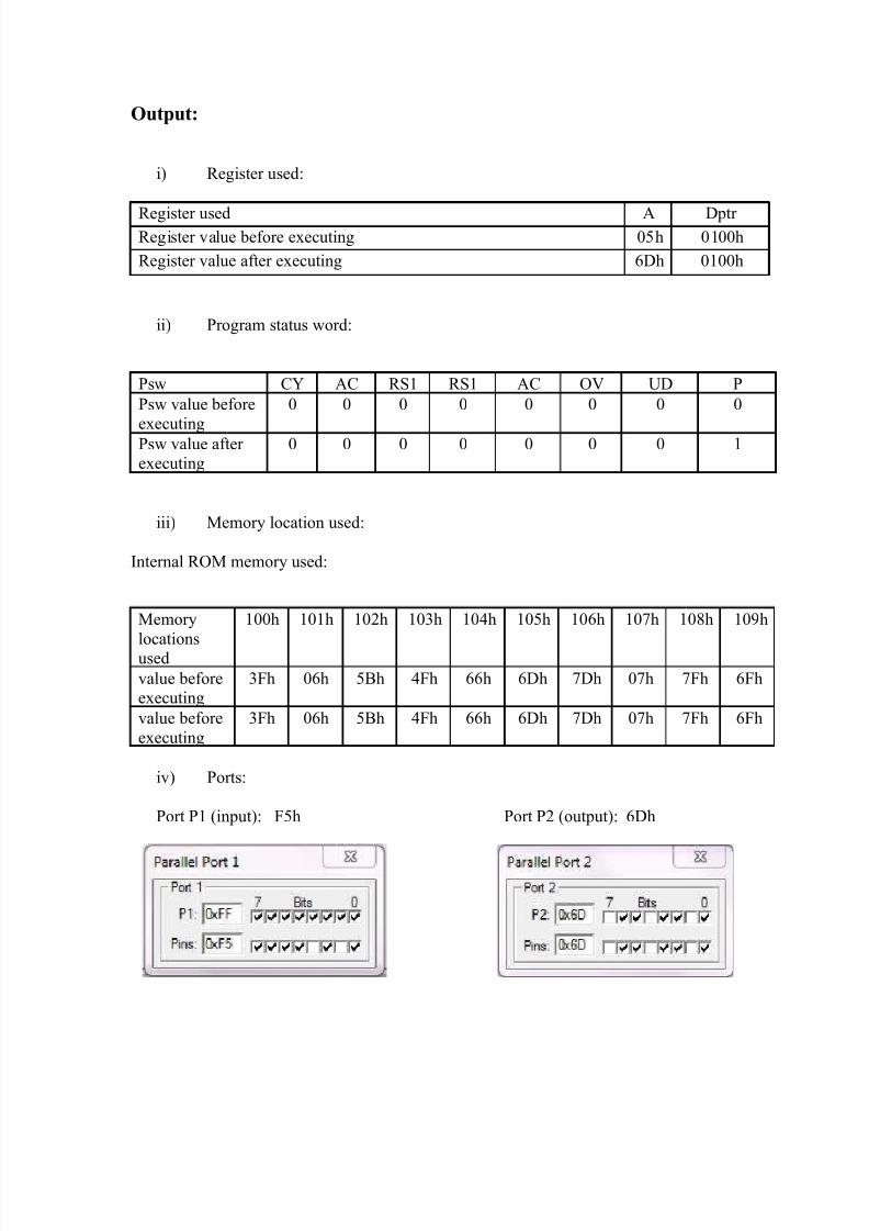
Output:
i) Register used:
Register used A Dptr Register value before executing 05h 0100h
Register value after executing 6Dh 0100h
ii) Program status word:
Psw CY AC RS1 RS1 AC OV UD P
Psw value before
executing
0 0 0 0 0 0 0 0
Psw value after executing
0 0 0 0 0 0 0 1
iii) Memory location used:
Internal ROM memory used:
iv) Ports:
Port P1 (input): F5h Port P2 (output): 6Dh
Memory
locationsused
100h 101h 102h 103h 104h 105h 106h 107h 108h 109h
value beforeexecuting
3Fh 06h 5Bh 4Fh 66h 6Dh 7Dh 07h 7Fh 6Fh
value before
executing
3Fh 06h 5Bh 4Fh 66h 6Dh 7Dh 07h 7Fh 6Fh

8/3/2019 Micro Controller File
http://slidepdf.com/reader/full/micro-controller-file 50/50
Conclusion: